Embed Size (px)
Citation preview

NATIONAL PROJECTS CONSTRUCTION CORPORATION LIMITED (A GOVT. OF INDIA ENTERPRISE)
NER (IBBW) OFFICE
House No.-2, SONAI ROAD, APANJANPALLY SILCHAR-788006(ASSAM)
℡-(03842)226995 Tele Fax-(03842)225089
www.npcc.gov.in
CONSTRUCTION OF BORDER OUT POST (BOP) FOR BSF ALONG INDO-BANGLADESH BORDER IN
THE STATE OF WEST BENGAL & TRIPURA
Pkg. No. – J (Tripura)
NIT No.:70064/IBBW/NIT/BOP/WS/783 DATED:01.12.2012
ISSUED TO:
CORPORATE OFFICE 67-68, SECTOR-25
FARIDABAD-121004 HARYANA
NPCCPR OJEC T EXC EL LENC E S IN C E 195 7
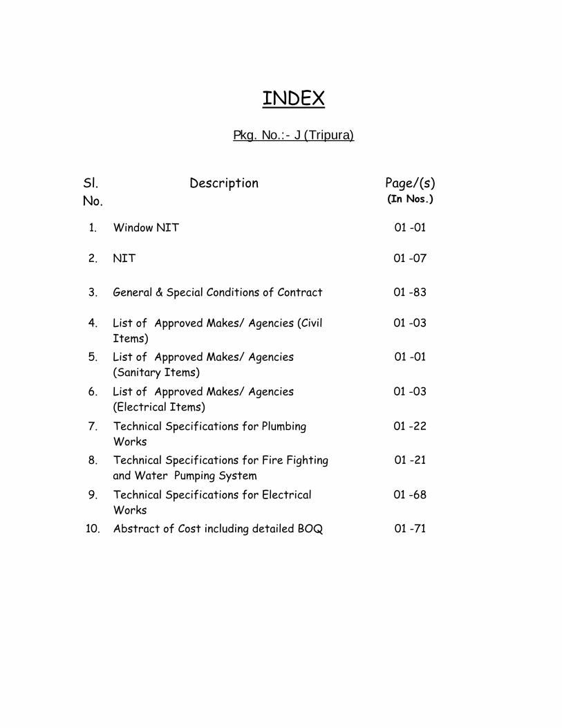
INDEX
Pkg. No.:- J (Tripura)
Sl. No.
Description Page/(s) (In Nos.)
1. Window NIT 01 -01
2. NIT 01 -07
3. General & Special Conditions of Contract 01 -83
4. List of Approved Makes/ Agencies (Civil
Items) 01 -03
5. List of Approved Makes/ Agencies
(Sanitary Items) 01 -01
6. List of Approved Makes/ Agencies
(Electrical Items) 01 -03
7. Technical Specifications for Plumbing
Works 01 -22
8. Technical Specifications for Fire Fighting
and Water Pumping System 01 -21
9. Technical Specifications for Electrical
Works 01 -68
10. Abstract of Cost including detailed BOQ 01 -71
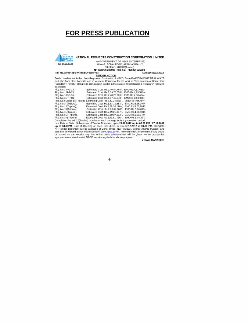
FOR PRESS PUBLICATION
NATIONAL PROJECTS CONSTRUCTION CORPORATION LIMITED (A GOVERNMENT OF INDIA ENTERPRISE)
ISO 9001-2008 H.No.-2, SONAI ROAD, APANJAN PALLY, SILCHAR- 788006(Assam)
- (03842) 226995 Tele Fax- (03842) 225089 NIT No.:70064/IBBW/NIT/BOP/WS/783 DATED:01/12/2012
TENDER NOTICE Sealed tenders are invited from Registered Contractor of NPCC/ State PWD/CPWD/MES/RAILWAYS and also from other bonafide and resourceful Contractor for the work of “Construction of Border Out Post (BOP) for BSF along Indo-Bangladesh Border in the state of West Bengal & Tripura” in following packages: Pkg. No.: JPG-03, Estimated Cost: Rs.2,40,84,460/-, EMD:Rs.4,81,689/- Pkg. No.: JPG-15, Estimated Cost: Rs.2,39,75,555/-, EMD:Rs.4,79,511/- Pkg. No.: JPG-16, Estimated Cost: Rs.2,40,20,209/-, EMD:Rs.4,80,404/- Pkg. No.: NTR-01 Estimated Cost: Rs.1,97,48,278/- EMD:Rs.3,94,966/- Pkg. No.: Group-B (Tripura), Estimated Cost: Rs.2,47,24,850/-, EMD:Rs.4,94,497/- Pkg. No.: I (Tripura), Estimated Cost: Rs.3,13,19,683/-, EMD:Rs.6,26,394/- Pkg. No.: J(Tripura), Estimated Cost: Rs.2,88,10,176/-, EMD:Rs.5,76,204/- Pkg. No.: K(Tripura), Estimated Cost: Rs.2,98,04,905/-, EMD:Rs.5,96,098/- Pkg. No.: L(Tripura), Estimated Cost: Rs.2,49,25,047/-, EMD:Rs.4,98,501/- Pkg. No.: M(Tripura), Estimated Cost: Rs.2,50,07,182/-, EMD:Rs.5,00,144/- Pkg. No.: N(Tripura), Estimated Cost: Rs.2,51,61,356/-, EMD:Rs.5,03,227/- Completion Period: 12(Twelve) months for each package including monsoon period. Last Date of Sale / Submission of Tender Document up to 24.12.2012 up to 05.00 PM / 27.12.2012 up to 04.00PM. Date of Opening of Tech. Bids (Envl.-1): On 27.12.2012 at 04.30 PM. Complete NIT/Tender Document will be available at Zonal Office, NER (IBBW), Silchar-788006 (Assam) and can also be viewed at our official website: www.npcc.gov.in. Amendments/Corrigendum, if any would be hosted on the website only. No further press advertisement will be given. Hence prospective agencies are advised to visit NPCC website regularly for above purpose. ZONAL MANAGER
-1-
NPCCPR OJE C T E XC EL LE NC E S IN C E 195 7
---1---
NATIONAL PROJECTS CONSTRUCTION CORPORATION LIMITED (A GOVERNMENT OF INDIA ENTERPRISE)
NER (IBBW) OFFICE, HOUSE No.-2, SONAI ROAD, APANJAN PALLY,
SILCHAR – 788006 (ASSAM) ISO 9001:2008 Tele-(03842)226995 TeleFax-(03842)225089
website: www.mowr.gov.in www.npcc.gov.in NIT NO.: 70064/IBBW/NIT/BOP/WS/783 DATED: 01.12.2012 SUB: CONSTRUCTION OF BORDER OUT POST (BOP) FOR BORDER SECURITY FORCE ALONG INDO-
BANGLADESH BORDER IN THE STATE OF WEST BENGAL & TRIPURA.
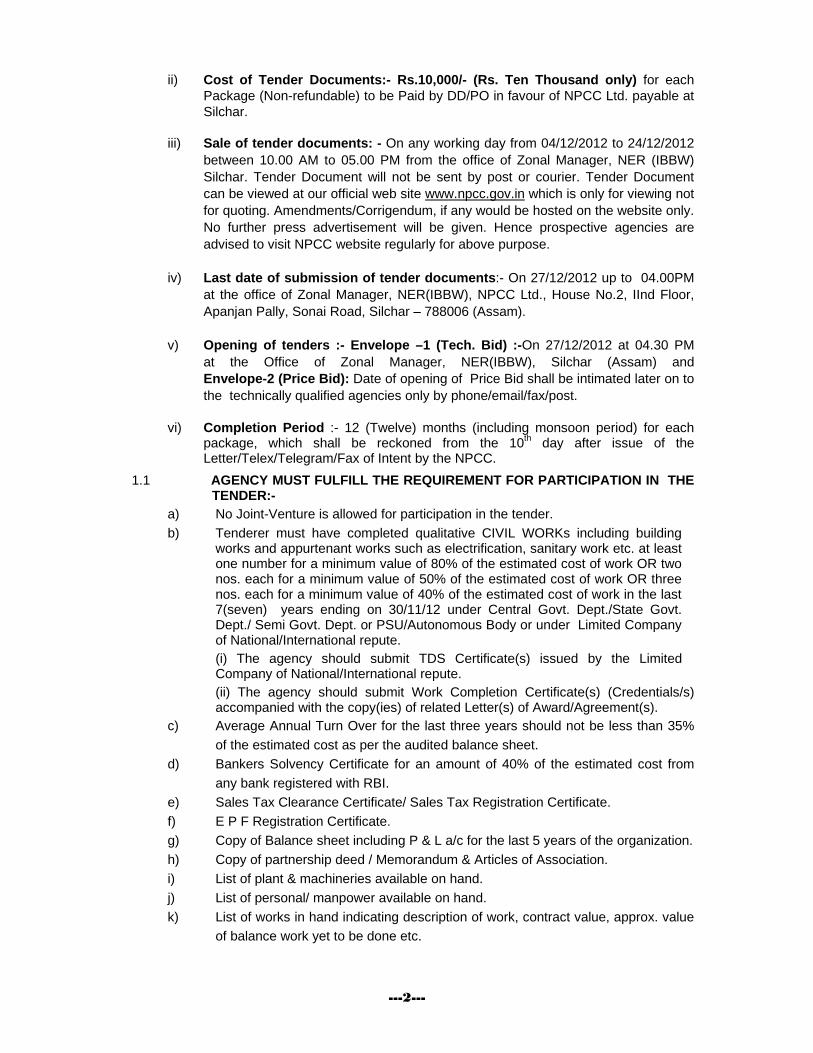
1.0 Sealed tenders are invited on behalf of Chairman-Cum-Managing Director (NPCC) from Registered Contractor of NPCC / State PWD / CPWD / MES / RAILWAYS and also from other bonafide and resourceful Contractor for the works as detailed below. A set of the tender documents along with a copy of the “Bill of Quantities” is enclosed herewith for submitting the tender.
Name of Work:-Construction of Border Out Post (BOP) for Border Security Force along Indo- Bangladesh the state of West Bengal & Tripura.
i) Earnest Money Deposit:-
The EMD shall be in the shape of D’call/Demand Draft in favour of NPCC Ltd. payable at Silchar or in the form of BG in the prescribed format from any Nationalized/Approved Scheduled Private Sector Bank. The EMD in any other form shall not be accepted.
State Group/Pkg. No. Name of BOPs Level BP
Reference
Estimated Cost
(In Rs.)
Earnest Money (In Rs.)
1 2 3 4 5 6 7 JPG-03 Bharat Pl. 762/2S 2,40,84,460.00 4,81,689.00
JPG-15 Jumagach Pl. 733/4S 2,39,75,555.00 4,79,511.00 WEST BENGAL
JPG-16 Takrabita Pl. 739/14R 2,40,20,209.00 4,80,404.00
NTR-01 Jeevantilla
Pl. 1875/M 1,97,48,278.00 3,94,966.00
Group-B (Tripura) Pushparampara
Pl. 2299 & 2300 2,47,24,850.00 4,94,497.00
I (Tripura) Durganagar
Pl. 1962/20S-
1965/M 3,13,19,683.00 6,26,394.00
J (Tripura) Anandaharipara
Coy. 2283 & 2284 2,88,10,176.00 5,76,204.00
K (Tripura) Kanthamonipara
Coy. 2285 & 2286 2,98,04,905.00 5,96,098.00
L (Tripura) Jalabasti
Pl. 2286 & 2287 2,49,25,047.00 4,98,501.00
M (Tripura) Sachindraraja Para
Pl. 2287 & 2288 2,50,07,182.00 5,00,144.00
TRIPURA
N (Tripura) Joymonipara
Pl. 2292 & 2294 2,51,61,356.00 5,03,227.00
NPCCPR OJEC T EXC EL LENC E S IN C E 195 7
---2---
ii) Cost of Tender Documents:- Rs.10,000/- (Rs. Ten Thousand only) for each Package (Non-refundable) to be Paid by DD/PO in favour of NPCC Ltd. payable at Silchar.
iii) Sale of tender documents: - On any working day from 04/12/2012 to 24/12/2012 between 10.00 AM to 05.00 PM from the office of Zonal Manager, NER (IBBW) Silchar. Tender Document will not be sent by post or courier. Tender Document can be viewed at our official web site www.npcc.gov.in which is only for viewing not for quoting. Amendments/Corrigendum, if any would be hosted on the website only. No further press advertisement will be given. Hence prospective agencies are advised to visit NPCC website regularly for above purpose.
iv) Last date of submission of tender documents:- On 27/12/2012 up to 04.00PM
at the office of Zonal Manager, NER(IBBW), NPCC Ltd., House No.2, IInd Floor, Apanjan Pally, Sonai Road, Silchar – 788006 (Assam).
v) Opening of tenders :- Envelope –1 (Tech. Bid) :-On 27/12/2012 at 04.30 PM
at the Office of Zonal Manager, NER(IBBW), Silchar (Assam) and Envelope-2 (Price Bid): Date of opening of Price Bid shall be intimated later on to the technically qualified agencies only by phone/email/fax/post.
vi) Completion Period :- 12 (Twelve) months (including monsoon period) for each
package, which shall be reckoned from the 10th day after issue of the Letter/Telex/Telegram/Fax of Intent by the NPCC.
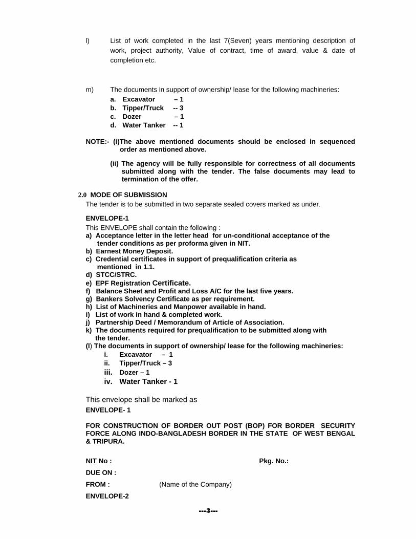
1.1 AGENCY MUST FULFILL THE REQUIREMENT FOR PARTICIPATION IN THE TENDER:-
a) No Joint-Venture is allowed for participation in the tender. b) Tenderer must have completed qualitative CIVIL WORKs including building
works and appurtenant works such as electrification, sanitary work etc. at least one number for a minimum value of 80% of the estimated cost of work OR two nos. each for a minimum value of 50% of the estimated cost of work OR three nos. each for a minimum value of 40% of the estimated cost of work in the last 7(seven) years ending on 30/11/12 under Central Govt. Dept./State Govt. Dept./ Semi Govt. Dept. or PSU/Autonomous Body or under Limited Company of National/International repute.
(i) The agency should submit TDS Certificate(s) issued by the Limited Company of National/International repute.
(ii) The agency should submit Work Completion Certificate(s) (Credentials/s) accompanied with the copy(ies) of related Letter(s) of Award/Agreement(s).
c) Average Annual Turn Over for the last three years should not be less than 35% of the estimated cost as per the audited balance sheet.
d) Bankers Solvency Certificate for an amount of 40% of the estimated cost from any bank registered with RBI.
e) Sales Tax Clearance Certificate/ Sales Tax Registration Certificate. f) E P F Registration Certificate. g) Copy of Balance sheet including P & L a/c for the last 5 years of the organization. h) Copy of partnership deed / Memorandum & Articles of Association. i) List of plant & machineries available on hand. j) List of personal/ manpower available on hand. k) List of works in hand indicating description of work, contract value, approx. value
of balance work yet to be done etc.
---3---
l) List of work completed in the last 7(Seven) years mentioning description of work, project authority, Value of contract, time of award, value & date of completion etc.
m) The documents in support of ownership/ lease for the following machineries:
a. Excavator – 1 b. Tipper/Truck -- 3 c. Dozer – 1 d. Water Tanker -- 1
NOTE:- (i)The above mentioned documents should be enclosed in sequenced order as mentioned above.
(ii) The agency will be fully responsible for correctness of all documents submitted along with the tender. The false documents may lead to termination of the offer.
2.0 MODE OF SUBMISSION
The tender is to be submitted in two separate sealed covers marked as under. ENVELOPE-1
This ENVELOPE shall contain the following : a) Acceptance letter in the letter head for un-conditional acceptance of the tender conditions as per proforma given in NIT. b) Earnest Money Deposit. c) Credential certificates in support of prequalification criteria as mentioned in 1.1. d) STCC/STRC. e) EPF Registration Certificate. f) Balance Sheet and Profit and Loss A/C for the last five years. g) Bankers Solvency Certificate as per requirement. h) List of Machineries and Manpower available in hand. i) List of work in hand & completed work. j) Partnership Deed / Memorandum of Article of Association. k) The documents required for prequalification to be submitted along with the tender. (l) The documents in support of ownership/ lease for the following machineries:
i. Excavator – 1 ii. Tipper/Truck – 3 iii. Dozer – 1 iv. Water Tanker - 1
This envelope shall be marked as
ENVELOPE- 1
FOR CONSTRUCTION OF BORDER OUT POST (BOP) FOR BORDER SECURITY FORCE ALONG INDO-BANGLADESH BORDER IN THE STATE OF WEST BENGAL & TRIPURA. NIT No : Pkg. No.: DUE ON : FROM : (Name of the Company) ENVELOPE-2
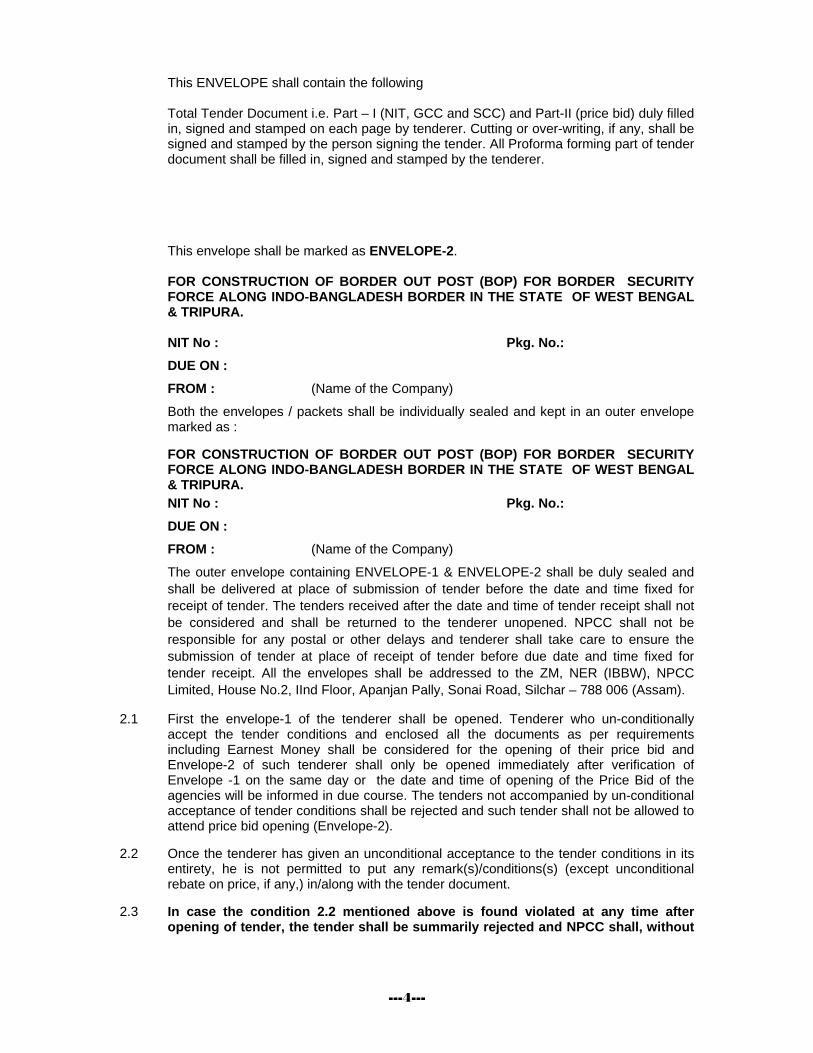
---4---
This ENVELOPE shall contain the following Total Tender Document i.e. Part – I (NIT, GCC and SCC) and Part-II (price bid) duly filled in, signed and stamped on each page by tenderer. Cutting or over-writing, if any, shall be signed and stamped by the person signing the tender. All Proforma forming part of tender document shall be filled in, signed and stamped by the tenderer. This envelope shall be marked as ENVELOPE-2. FOR CONSTRUCTION OF BORDER OUT POST (BOP) FOR BORDER SECURITY FORCE ALONG INDO-BANGLADESH BORDER IN THE STATE OF WEST BENGAL & TRIPURA. NIT No : Pkg. No.: DUE ON : FROM : (Name of the Company) Both the envelopes / packets shall be individually sealed and kept in an outer envelope marked as : FOR CONSTRUCTION OF BORDER OUT POST (BOP) FOR BORDER SECURITY FORCE ALONG INDO-BANGLADESH BORDER IN THE STATE OF WEST BENGAL & TRIPURA.
NIT No : Pkg. No.: DUE ON : FROM : (Name of the Company) The outer envelope containing ENVELOPE-1 & ENVELOPE-2 shall be duly sealed and shall be delivered at place of submission of tender before the date and time fixed for receipt of tender. The tenders received after the date and time of tender receipt shall not be considered and shall be returned to the tenderer unopened. NPCC shall not be responsible for any postal or other delays and tenderer shall take care to ensure the submission of tender at place of receipt of tender before due date and time fixed for tender receipt. All the envelopes shall be addressed to the ZM, NER (IBBW), NPCC Limited, House No.2, IInd Floor, Apanjan Pally, Sonai Road, Silchar – 788 006 (Assam).
2.1 First the envelope-1 of the tenderer shall be opened. Tenderer who un-conditionally accept the tender conditions and enclosed all the documents as per requirements including Earnest Money shall be considered for the opening of their price bid and Envelope-2 of such tenderer shall only be opened immediately after verification of Envelope -1 on the same day or the date and time of opening of the Price Bid of the agencies will be informed in due course. The tenders not accompanied by un-conditional acceptance of tender conditions shall be rejected and such tender shall not be allowed to attend price bid opening (Envelope-2).
2.2 Once the tenderer has given an unconditional acceptance to the tender conditions in its
entirety, he is not permitted to put any remark(s)/conditions(s) (except unconditional rebate on price, if any,) in/along with the tender document.
2.3 In case the condition 2.2 mentioned above is found violated at any time after
opening of tender, the tender shall be summarily rejected and NPCC shall, without
---5---
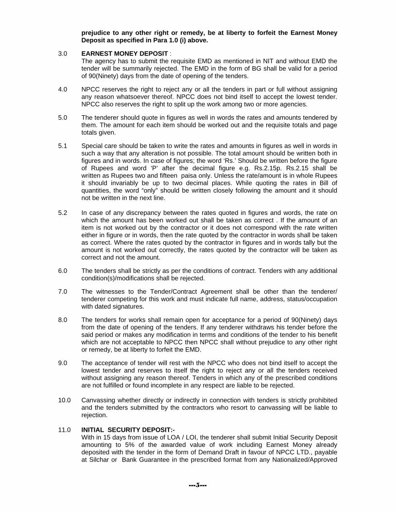
prejudice to any other right or remedy, be at liberty to forfeit the Earnest Money Deposit as specified in Para 1.0 (i) above.
3.0 EARNEST MONEY DEPOSIT :
The agency has to submit the requisite EMD as mentioned in NIT and without EMD the tender will be summarily rejected. The EMD in the form of BG shall be valid for a period of 90(Ninety) days from the date of opening of the tenders.
4.0 NPCC reserves the right to reject any or all the tenders in part or full without assigning any reason whatsoever thereof. NPCC does not bind itself to accept the lowest tender. NPCC also reserves the right to split up the work among two or more agencies.
5.0 The tenderer should quote in figures as well in words the rates and amounts tendered by
them. The amount for each item should be worked out and the requisite totals and page totals given.
5.1 Special care should be taken to write the rates and amounts in figures as well in words in
such a way that any alteration is not possible. The total amount should be written both in figures and in words. In case of figures; the word ‘Rs.’ Should be written before the figure of Rupees and word ‘P’ after the decimal figure e.g. Rs.2.15p. Rs.2.15 shall be
written as Rupees two and fifteen paisa only. Unless the rate/amount is in whole Rupees it should invariably be up to two decimal places. While quoting the rates in Bill of quantities, the word “only” should be written closely following the amount and it should not be written in the next line.
5.2 In case of any discrepancy between the rates quoted in figures and words, the rate on
which the amount has been worked out shall be taken as correct . If the amount of an item is not worked out by the contractor or it does not correspond with the rate written either in figure or in words, then the rate quoted by the contractor in words shall be taken as correct. Where the rates quoted by the contractor in figures and in words tally but the amount is not worked out correctly, the rates quoted by the contractor will be taken as correct and not the amount.
6.0 The tenders shall be strictly as per the conditions of contract. Tenders with any additional
condition(s)/modifications shall be rejected. 7.0 The witnesses to the Tender/Contract Agreement shall be other than the tenderer/
tenderer competing for this work and must indicate full name, address, status/occupation with dated signatures.
8.0 The tenders for works shall remain open for acceptance for a period of 90(Ninety) days
from the date of opening of the tenders. If any tenderer withdraws his tender before the said period or makes any modification in terms and conditions of the tender to his benefit which are not acceptable to NPCC then NPCC shall without prejudice to any other right or remedy, be at liberty to forfeit the EMD.
9.0 The acceptance of tender will rest with the NPCC who does not bind itself to accept the
lowest tender and reserves to itself the right to reject any or all the tenders received without assigning any reason thereof. Tenders in which any of the prescribed conditions are not fulfilled or found incomplete in any respect are liable to be rejected.
10.0 Canvassing whether directly or indirectly in connection with tenders is strictly prohibited
and the tenders submitted by the contractors who resort to canvassing will be liable to rejection.
11.0 INITIAL SECURITY DEPOSIT:-
With in 15 days from issue of LOA / LOI, the tenderer shall submit Initial Security Deposit amounting to 5% of the awarded value of work including Earnest Money already deposited with the tender in the form of Demand Draft in favour of NPCC LTD., payable at Silchar or Bank Guarantee in the prescribed format from any Nationalized/Approved
---6---
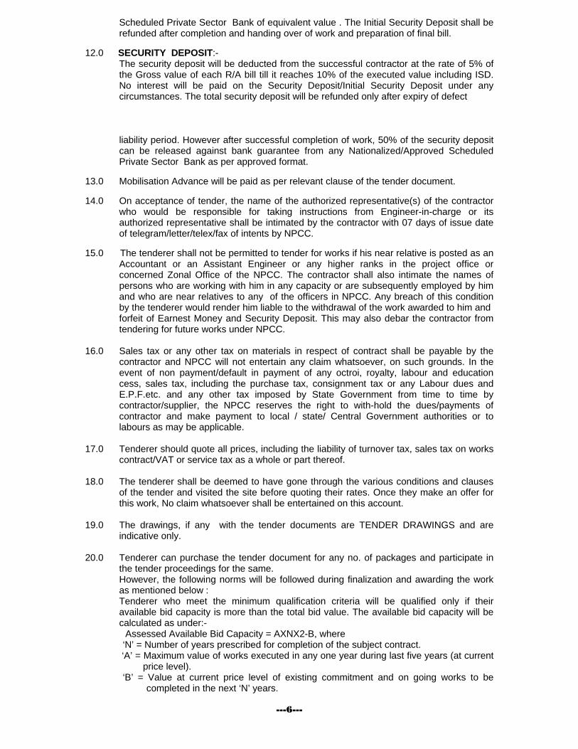
Scheduled Private Sector Bank of equivalent value . The Initial Security Deposit shall be refunded after completion and handing over of work and preparation of final bill.
12.0 SECURITY DEPOSIT:-
The security deposit will be deducted from the successful contractor at the rate of 5% of the Gross value of each R/A bill till it reaches 10% of the executed value including ISD. No interest will be paid on the Security Deposit/Initial Security Deposit under any circumstances. The total security deposit will be refunded only after expiry of defect liability period. However after successful completion of work, 50% of the security deposit can be released against bank guarantee from any Nationalized/Approved Scheduled Private Sector Bank as per approved format.
13.0 Mobilisation Advance will be paid as per relevant clause of the tender document. 14.0 On acceptance of tender, the name of the authorized representative(s) of the contractor
who would be responsible for taking instructions from Engineer-in-charge or its authorized representative shall be intimated by the contractor with 07 days of issue date of telegram/letter/telex/fax of intents by NPCC.
15.0 The tenderer shall not be permitted to tender for works if his near relative is posted as an
Accountant or an Assistant Engineer or any higher ranks in the project office or concerned Zonal Office of the NPCC. The contractor shall also intimate the names of persons who are working with him in any capacity or are subsequently employed by him and who are near relatives to any of the officers in NPCC. Any breach of this condition by the tenderer would render him liable to the withdrawal of the work awarded to him and
forfeit of Earnest Money and Security Deposit. This may also debar the contractor from tendering for future works under NPCC.
16.0 Sales tax or any other tax on materials in respect of contract shall be payable by the
contractor and NPCC will not entertain any claim whatsoever, on such grounds. In the event of non payment/default in payment of any octroi, royalty, labour and education cess, sales tax, including the purchase tax, consignment tax or any Labour dues and E.P.F.etc. and any other tax imposed by State Government from time to time by contractor/supplier, the NPCC reserves the right to with-hold the dues/payments of contractor and make payment to local / state/ Central Government authorities or to labours as may be applicable.
17.0 Tenderer should quote all prices, including the liability of turnover tax, sales tax on works
contract/VAT or service tax as a whole or part thereof. 18.0 The tenderer shall be deemed to have gone through the various conditions and clauses
of the tender and visited the site before quoting their rates. Once they make an offer for this work, No claim whatsoever shall be entertained on this account.
19.0 The drawings, if any with the tender documents are TENDER DRAWINGS and are
indicative only. 20.0 Tenderer can purchase the tender document for any no. of packages and participate in
the tender proceedings for the same. However, the following norms will be followed during finalization and awarding the work as mentioned below : Tenderer who meet the minimum qualification criteria will be qualified only if their available bid capacity is more than the total bid value. The available bid capacity will be calculated as under:- Assessed Available Bid Capacity = AXNX2-B, where ‘N’ = Number of years prescribed for completion of the subject contract.
‘A’ = Maximum value of works executed in any one year during last five years (at current price level).
‘B’ = Value at current price level of existing commitment and on going works to be completed in the next ‘N’ years.
---7---
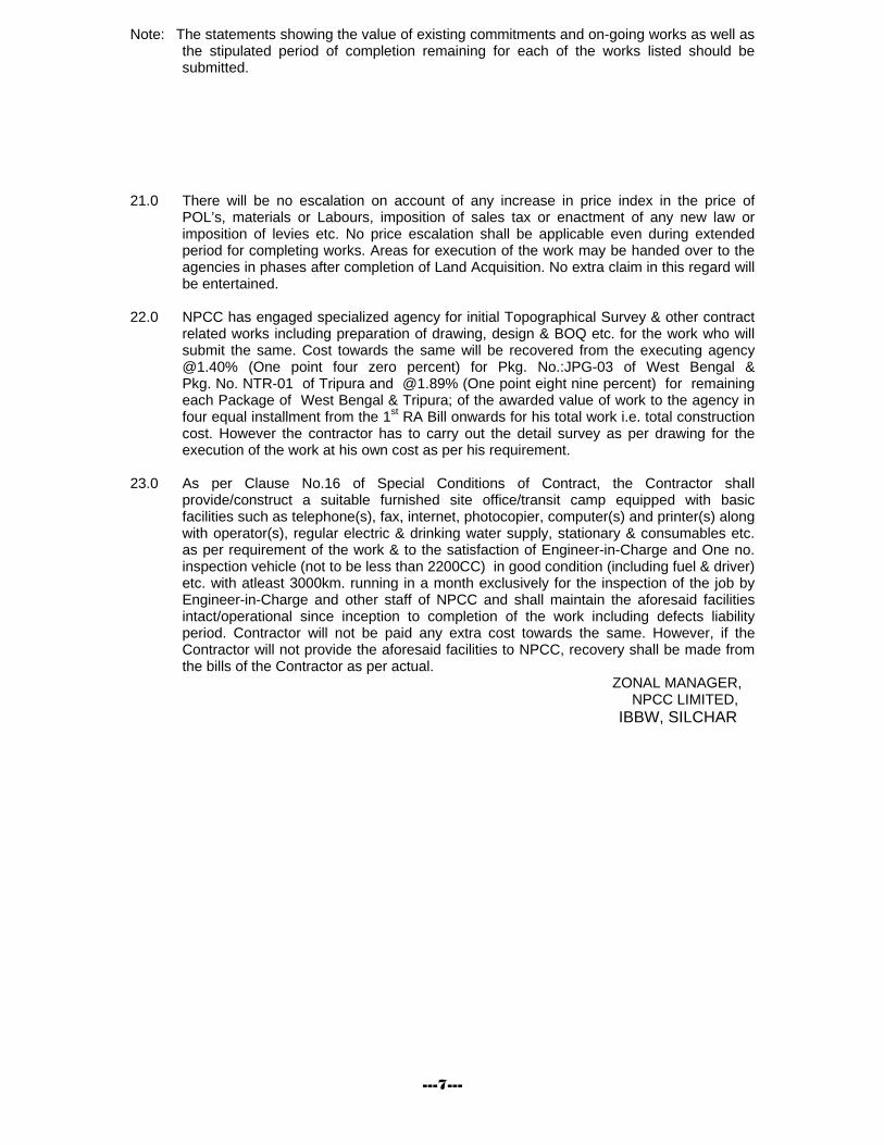
Note: The statements showing the value of existing commitments and on-going works as well as the stipulated period of completion remaining for each of the works listed should be submitted.
21.0 There will be no escalation on account of any increase in price index in the price of
POL’s, materials or Labours, imposition of sales tax or enactment of any new law or imposition of levies etc. No price escalation shall be applicable even during extended period for completing works. Areas for execution of the work may be handed over to the agencies in phases after completion of Land Acquisition. No extra claim in this regard will be entertained.
22.0 NPCC has engaged specialized agency for initial Topographical Survey & other contract
related works including preparation of drawing, design & BOQ etc. for the work who will submit the same. Cost towards the same will be recovered from the executing agency @1.40% (One point four zero percent) for Pkg. No.:JPG-03 of West Bengal & Pkg. No. NTR-01 of Tripura and @1.89% (One point eight nine percent) for remaining each Package of West Bengal & Tripura; of the awarded value of work to the agency in four equal installment from the 1st RA Bill onwards for his total work i.e. total construction cost. However the contractor has to carry out the detail survey as per drawing for the execution of the work at his own cost as per his requirement.
23.0 As per Clause No.16 of Special Conditions of Contract, the Contractor shall
provide/construct a suitable furnished site office/transit camp equipped with basic facilities such as telephone(s), fax, internet, photocopier, computer(s) and printer(s) along with operator(s), regular electric & drinking water supply, stationary & consumables etc. as per requirement of the work & to the satisfaction of Engineer-in-Charge and One no. inspection vehicle (not to be less than 2200CC) in good condition (including fuel & driver) etc. with atleast 3000km. running in a month exclusively for the inspection of the job by Engineer-in-Charge and other staff of NPCC and shall maintain the aforesaid facilities intact/operational since inception to completion of the work including defects liability period. Contractor will not be paid any extra cost towards the same. However, if the Contractor will not provide the aforesaid facilities to NPCC, recovery shall be made from the bills of the Contractor as per actual.
ZONAL MANAGER, NPCC LIMITED, IBBW, SILCHAR

TENDER FOR CONSTRUCTION OF BORDER OUT POST FOR BSF ALONG INDO-BANGLADESH BORDER
Conditions of Contract Page 1 of 83 N.P.C.C.
ACCEPTANCE LETTER
TO BE ENCLOSED IN ENVELOPE – 1 The Zonal Manager, NER(IBBW), NPCC Ltd., H.No.2, IInd Floor, Apanjan Pally, Sonai Road, Silchar – 788 006 (Assam) Sir,
ACCEPTANCE OF NPCC’s TENDER CONDITIONS
1. The tender documents for the work “CONSTRUCTION OF BORDER OUT POSTS (BOP)
FOR BORDER SECURITY FORCE ALONG INDO-BANGLADESH BORDER IN THE STATE OF WEST BENGAL & TRIPURA” for Package No.________________________at BP No.........................................” have been sold to me/us by National Project Construction Corporation Limited and I/We hereby certified that I/We have inspected and read the entire terms and conditions of the Tender Document made available to me/us in the Office of Zonal Manager, NER(IBBW), NPCC Ltd., SILCHAR which shall form part of the contract agreement and I/We shall abide by the conditions/clauses contained therein.
2. I/We hereby unconditionally accept the tender conditions of the NPCC’s Tender Documents in its entirety for the above work. 3. The contents of Para 4 (Four) of Special Conditions of the Tender documents have been
noted wherein it is clarified that after unconditionally accepting the tender condition in its entirety, it is not permissible to put any remark(s)/conditions(s) (except unconditional rebate on price, if any) in the tender enclosed in “Envelope-2” and the same has been followed in the present case. In case this provision of the tender is found violated at any time after opening of the Envelope 2, I/we agree that the tender shall be summarily rejected and NPCC shall, without prejudice to any other right or remedy be at liberty to forfeit the full said earnest money absolutely.
4. The required earnest money for this work is enclosed herewith. 5. If I/we will not fulfill the minimum qualifying criteria of the tender I/we not lodge any claim for
opening of envelope 2 of the tender. 6. I/We hereby undertake that I/We will be fully responsible for the correctness of all
credentials/ documents submitted along with the tender. 7. If at any stage, the credentials/documents submitted along with the tender by me/us are
found false/incorrect; NPCC Ltd. may have absolute right to blacklist me/us or terminate the offer/work.
Yours faithfully, (Signature of the tenderer) With rubber stamp
Dated : _____________
TENDER FOR CONSTRUCTION OF BORDER OUT POST FOR BSF ALONG INDO-BANGLADESH BORDER
Conditions of Contract Page 2 of 83 N.P.C.C.
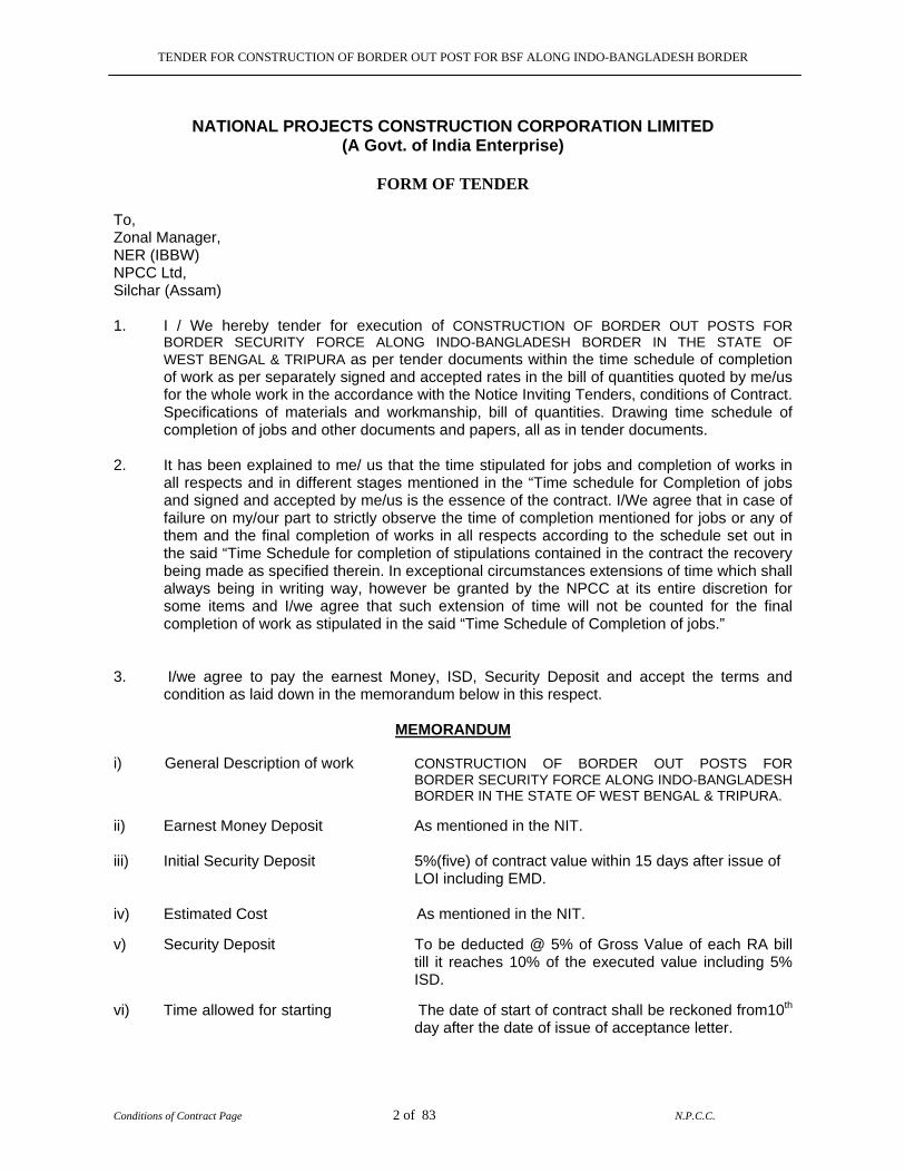
NATIONAL PROJECTS CONSTRUCTION CORPORATION LIMITED
(A Govt. of India Enterprise)
FORM OF TENDER To, Zonal Manager, NER (IBBW) NPCC Ltd, Silchar (Assam) 1. I / We hereby tender for execution of CONSTRUCTION OF BORDER OUT POSTS FOR
BORDER SECURITY FORCE ALONG INDO-BANGLADESH BORDER IN THE STATE OF WEST BENGAL & TRIPURA as per tender documents within the time schedule of completion of work as per separately signed and accepted rates in the bill of quantities quoted by me/us for the whole work in the accordance with the Notice Inviting Tenders, conditions of Contract. Specifications of materials and workmanship, bill of quantities. Drawing time schedule of completion of jobs and other documents and papers, all as in tender documents.
2. It has been explained to me/ us that the time stipulated for jobs and completion of works in
all respects and in different stages mentioned in the “Time schedule for Completion of jobs and signed and accepted by me/us is the essence of the contract. I/We agree that in case of failure on my/our part to strictly observe the time of completion mentioned for jobs or any of them and the final completion of works in all respects according to the schedule set out in the said “Time Schedule for completion of stipulations contained in the contract the recovery being made as specified therein. In exceptional circumstances extensions of time which shall always being in writing way, however be granted by the NPCC at its entire discretion for some items and I/we agree that such extension of time will not be counted for the final completion of work as stipulated in the said “Time Schedule of Completion of jobs.”
3. I/we agree to pay the earnest Money, ISD, Security Deposit and accept the terms and
condition as laid down in the memorandum below in this respect.
MEMORANDUM i) General Description of work CONSTRUCTION OF BORDER OUT POSTS FOR
BORDER SECURITY FORCE ALONG INDO-BANGLADESH BORDER IN THE STATE OF WEST BENGAL & TRIPURA.
ii) Earnest Money Deposit As mentioned in the NIT. iii) Initial Security Deposit 5%(five) of contract value within 15 days after issue of
LOI including EMD.
iv) Estimated Cost As mentioned in the NIT. v) Security Deposit To be deducted @ 5% of Gross Value of each RA bill till it reaches 10% of the executed value including 5% ISD.
vi) Time allowed for starting The date of start of contract shall be reckoned from10th day after the date of issue of acceptance letter.
TENDER FOR CONSTRUCTION OF BORDER OUT POST FOR BSF ALONG INDO-BANGLADESH BORDER
Conditions of Contract Page 3 of 83 N.P.C.C.
vii) Time for completion of work Total work to be completed in accordance with the time schedule of completion of work in the tender documents.
viii) Location of the work:- As mentioned in the NIT. 4. Should this tender be accepted, I/We agree to abide by and fulfill all terms and conditions
referred to above and in default thereof, to forfeit, and pay NPCC or its successors or its authorized nominees such sums of money as are stipulated in the notice inviting tender documents.
5. If I/We fail to commence the work within 10 days of the date of issue of LOI, or I/We fail to
submit performance guarantee as per Clause-09 of General conditions of contract I/We agree that NPCC shall, without prejudice to any other right or remedy, be at liberty to forfeit the said earnest money deposited with NPCC as specified above besides any other action as per terms of registration with NPCC. The NPCC shall also be at liberty to cancel the notice of acceptance of tender if we fail to deposit the performance bank guarantee as contained elsewhere in the tender documents.
6. I/We are also enclosing herewith the Acceptance letter on the prescribed pro-forma as
referred to in condition of NIT. Dated the__________________ day of _________ SIGNATURE OF TENDERER NAME IN CAPITAL LETTERS ___________ ADDRESS ___________________________ ___________________________________ SEAL OF TENDERER WITNESS OCCUPATION._________________________
TENDER FOR CONSTRUCTION OF BORDER OUT POST FOR BSF ALONG INDO-BANGLADESH BORDER
Conditions of Contract Page 4 of 83 N.P.C.C.
GENERAL CONDITIONS OF CONTRACT 1.0 GENERAL:
The contract means the documents forming the tender and acceptance and thereof and the formal agreement executed between the competent authority on behalf of NPCC and the contractor together with the documents referred to therein including these conditions; the specifications; designs; drawings and instructions issued from time to time by the Engineer-in Charge and all these documents taken together, shall be deemed to form one contract and shall be complementary to one another.
1.1 In the contract, the following expressions shall unless the context otherwise requires, have the meaning hereby respectively assigned to them .
1.2 EXECUTIVE AGENCY:
Executive Agency means M/s N P C C Ltd. (A Govt. of India Enterprise) referred as NPCC who has been retained as agent by Ministry of Home Affairs (Govt. of India) for “CONSTRUCTION OF BORDER OUT POSTS (BOPs) FOR BORDER SECURITY FORCE ALONG INDO-BANGLADESH BORDER IN THE STATE OF WEST BENGAL & TRIPURA”.
1.3 National Projects Construction Corporation Ltd. Herein after called NPCC propose to complete the CONSTRUCTION OF BORDER OUT POSTS (BOPs) FOR BORDER SECURITY FORCE ALONG INDO-BANGLADESH BORDER IN THE STATE OF WEST BENGAL & TRIPURA. The work will be executed as per drawings “GOOD FOR CONSTRUCTION” to be released by NPCC
1.4 OTHER DEFINITIONS:
a) ZONAL MANAGER means the Engineer of NPCC heading the zone having Indo-Bangladesh Border works.
b) ENGINEER –IN-CHARGE means the Engineer of NPCC who shall supervise and be
in- charge of the work from time to time.
c) WORKS OR WORK The expression works or work shall unless there be something either in the subject or context repugnant to such construction be construed and taken to mean the works by or by virtue of the contract contracted to be executed whether temporary or permanent, and whether original altered substituted or additional.
d) CONTRACTOR The contractor shall mean the individual firm or company whether in
corporate or not undertaking the works and shall include the legal personal representative or such individual or the persons composing such firm or company, or the successors of such firm or company and the permitted assignees of such individual firm or company.
e) DRAWINGS mean the drawings referred to in the specifications and any modifications of
such drawings or such other drawings as may from time to time be furnished or approved by NPCC
f) SITE means the lands and other places on under, in or through which the works are to
be executed or carried out and any other lands or places provided by NPCC or used for the purpose of the agreement.
TENDER FOR CONSTRUCTION OF BORDER OUT POST FOR BSF ALONG INDO-BANGLADESH BORDER
Conditions of Contract Page 5 of 83 N.P.C.C.
g) APPROVAL means approved in writing including subsequent written confirmation of
previous verbal approval. h) WRITING means any manuscript typed written or printed statement under or over
signature and / or seal as the case may be. i) MONTH means English Calendar month ‘Day’ means a Calendar day or 24 Hrs. each. j) CONTRACT VALUE means the sum for which the tender is accepted as per the letter of
intent. k) LANGUAGE All documents and correspondence in respect of this contract shall be in
English Language. l) BILL OF QUANTITIES OR SCHEDULE OF QUANTITIES means the priced and
completed Bill of Quantities or Schedule of Quantities forming part of the tender.
m) TENDER means the Contractor’s priced offer to NPCC for the execution and completion of the work and the remedying of any defects therein in accordance with the provisions of the Contract, as accepted by the Letter of Intent or Award letter The word TENDER is synonymous with Bid and the word TENDER DOCUMENTS with “Bidding Documents” or “offer documents”.
n) The headings in the clauses/ conditions of tender documents is for convenience only and
shall not be used for interpretation of the clause / condition. o) Words imparting the singular only also include the final and vice versa where the context
requires.
2.0 INTRODUCTION TO WORK SITE: 2.1 The proposed site for construction of BOP falls on Indo-Bangladesh International Border at
different locations. Contractor is advised to inspect the site and its surrounding thoroughly and satisfy himself before submitting tender as to the nature of the ground and the means of access to the site, the facilities available at site etc. In general contractor shall themselves obtain all required information as to the risks, contingencies & Pre-verify conditions in the area & all other circumstances which, according to them, may influence or affect the rates.
The tenderer shall be deemed to have visited the site and made themselves familiar with the working conditions and to have the knowledge of the site. Whether he actually inspect it or not NPCC shall not be liable for any extra charge/ claim consequent upon any misunderstanding or otherwise.
2.2 ACCESS BY ROAD:
Contractor if necessary shall build temporary access roads to the actual site of construction for the works at his own cost. The contractor shall be required to permit the use of any roads so constructed by him for vehicles of NPCC or any other agencies/ contractors who may be engaged on the project site, free of cost. Non-availability to access roads, for the use of the contractor shall in no case condone any delay in the execution of work nor be the cause for any claim for compensation.

TENDER FOR CONSTRUCTION OF BORDER OUT POST FOR BSF ALONG INDO-BANGLADESH BORDER
Conditions of Contract Page 6 of 83 N.P.C.C.
3.0 SCOPE OF WORK: 3.1 The scope of work covered in this tender shall be as per the specifications, drawings issued
to the contractor from time to time during the pendency or work. The drawings for this work, which may be referred for tendering provide general idea only about the work to be performed under the scope of this contract. These may not be the final drawings and may not or indicate the full range of the work under the scope of this contract. The work will be executed according to the drawings to be released as “GOOD FOR CONSTRUCTION” from time to time by the Engineer-In-Charge/Zonal Manager of NPCC and according to any additions/ modifications/ alterations/ deletions made from time to time as required by any other drawings that would be issued to the contractor progressively during execution of work. It shall be the responsibility of the contractor to incorporate the changes that may be in this scope of work, envisaged at the time of tendering and as actually required to be executed.
3.2 The quantities of various items as entered in the “BILL OF QUANTITIES” are indicative only and may vary depending upon the actual requirement. The contractor shall be bound to carry out and complete the stipulated work irrespective of the variation in individual items specified in the bill of quantities. The variation of quantities will be as per General conditions of contract.
4.0 VALIDITY OF TENDER:
The tender for the works shall remain open for acceptance for a period of 90 (Ninety) days from the date of opening of tenderers. The Earnest Money will be forfeited in case the contractor withdraws his tender during the validity period or in case he changes his offer to his benefits which are not acceptable to NPCC. The validity period may be extended on mutual consent.
5.0 ACCEPTANCE OF TENDER:
The NPCC reserves to itself the authority to reject any or all the tenders received without assigning any reason. The acceptance of a tender shall be effective w.e.f. the date on which the telegram/ letter of intent of acceptance of the tender is put in the communication by the NPCC.
6.0 SET OF CONTRACT DOCUMENTS: The following documents will complete a set of tender document.
1. Notice Inviting Tenders and Instructions to Tenderer 2. General Conditions of contract including special conditions of contract and prescribed formats. 3. Schedule of Rates/Bills of Quantities. 4. Technical Specifications (General, Additional & Technical specification) 5. Tender Drawings.
7.0 SIGNING OF AGREEMENT:
Contractor shall purchase 4 Nos. agreement paper @ Rs.10,000/- (Rs. Ten Thousand only i.e. same as cost of tender document) each and shall complete all the formalities and sign the agreement within 15 days of issue of letter of intent. In case, the contractor does not sign the agreement as above or start the work within 10 days of the issue of letter/telegram of intent, his earnest money deposited with NPCC as stipulated herein before is liable to be forfeited and letter of intent consequently will stand withdrawn.
TENDER FOR CONSTRUCTION OF BORDER OUT POST FOR BSF ALONG INDO-BANGLADESH BORDER
Conditions of Contract Page 7 of 83 N.P.C.C.
7.1 The agreement shall be executed on non-judicial stamp paper of appropriate value and the cost of the stamp paper shall be borne by the contractor.
7.2 The stamp duty if any on the contract agreement levied by the Government or any other
statutory body shall be paid by the contractor. 8.0 MOBILIZATION ADVANCE:
i) The Mobilization Advance will be limited to 5%(five Percent) of the Contract Value against submission of irrevocable Bank Guarantee of an amount 1.20times of the Mobilisation Advance to take care of advance and interest. Rate of interest on Mobilization Advance shall be 10% (Ten Percent) simple interest on reducing balance. The advance will be paid in two stages as under: Stage-I: 02%(Two Percent) of contract value on signing of contract and submission of ISD/ Performance Guarantee. Stage-II: 03%(Three Percent) of contract value on establishment of site office/ transit camp, mobilization of plant & machineries at site (including as per tender document), manpower & infrastructure facilities for commencement of work.
ii) Each stage advance will only be made after the Engineer-In –Charge / Zonal Manager is satisfied that the amount of advance earlier has actually been utilized for the purpose for which given based on the details to be furnished by the contractor.
iii) The advance shall be paid only against a Bank Guarantee for the principal plus interest from any Nationalized/ Approved Scheduled Private Sector Bank in a form and manner acceptable to the Corporation as per approved format, valid till expiry of contract.
iv) Advance shall be recovered progressively from the 1st Running Account bill of the contractor at 15% to 20% or as decided by the Engineer-in-Charge, of the value of each bill from each bill along with the interest due thereon so that by the time 75% of the contract value is paid, the entire advance together with interest up to that date will have been recovered.
v) Interest will be computed on diminishing balance basis on the amount of advance outstanding. The date of issue of Cheque will be reckoned as the date on which the recovery has been made for purposes of computing the outstanding and working out the interest.
vi) The BG for advances shall be released progressively on recovery of the respective amount of Mobilization Advance.
9.0 INITIAL SECURITY DEPOSIT:
Within 15days from issue of LOA / LOI, the contractor shall submit Initial Security Deposit amounting to 5% of the awarded value of work including Earnest Money already deposited with the tender in the form of Demand Draft in favour of NPCC LTD., payable at Silchar or Bank Guarantee in the prescribed format from any Nationalized/Approved Scheduled Private Sector Bank of equivalent value. The Initial Security Deposit shall be refunded after completion and handing over of work and preparation of final bill.
10.0 SECURITY DEPOSIT:
The security deposit will be deducted from the successful contractor at the rate of 5% of the Gross value of each R/A bill till it reaches 10% of the executed value including ISD. No interest will be paid on the Security Deposit/Initial Security Deposit under any circumstances. The total security deposit will be refunded only after expiry of defect liability period or on payment of final bill, whichever is later. However after successful completion of work, 50% of the security deposit can be released against bank guarantee from any Nationalized/Approved Scheduled Private Sector Bank as per approved format.
TENDER FOR CONSTRUCTION OF BORDER OUT POST FOR BSF ALONG INDO-BANGLADESH BORDER
Conditions of Contract Page 8 of 83 N.P.C.C.
11.0 MOBILIZATION OF MEN, MATERIALS AND MACHINERY: 11.1 All expenses towards mobilization at site and de-mobilization including bringing in
equipment, work force, materials, dismantling the equipments, clearing the site etc. shall be deemed to be included in prices quoted and no separate payment on account of such expenses shall be entertained.
11.2 It shall be entirely the Contractor’s responsibility to provide, operate and maintain all
necessary construction equipments, scaffoldings and safety, gadget, lifting tackles, tools and appliances to perform the work in a workman like and efficient manner and complete all jobs as per the specifications and within the schedule time of completion of work. Further, contractor shall also be responsible for obtaining temporary electric and water connection for all purposes. The contractor shall also make standby arrangement for water & electricity to ensure un-interrupted supply.
11.3 It shall be the responsibility of the contractor to obtain the approval for any revision and / or
modification desired by him from NPCC before implementation. Also such revisions and / or modifications if accepted / approved by the NPCC shall be carried at no extra cost to NPCC.
11.4 The procurement and supply in sequence and at the appropriate time of all materials and
consumable shall be entirely the contractor’s responsibilities and his rates for execution of work shall be inclusive of supply of all these items.
11.5 All designs, drawings, bill of quantities, etc for all works shall be supplied to the contractor for all structures, services and development works by NPCC in phased manner as the works progress. However it shall be the duty and responsibility of the contractor to bring to the notice of the NPCC in writing as to any variation, discrepancy or any other changes required and to obtain revised drawings and designs and / or approval of the NPCC in writing for the same.
11.6 One copy of contract documents including drawings furnished to the contractor shall be kept
at the side and the same shall at all reasonable times be available for inspection. 11.7 All materials construction plants and equipments etc. once brought by the contractor within
the project area will not be allowed to be removed from the premises without the written permission of the NPCC. Similarly all enabling works built by the contractor for the main construction undertaken by him, shall not be dismantled and removed without the written authority of the NPCC.
11.8 Contractor shall have to prepare the shop drawings free of cost if required for any of the
items of work. Five copies of these shop drawings each including for revision will be submitted to NPCC for approval. Before executing the item shop drawings should be approved by NPCC.
11.9 UTILIZATION OF WORK FORCE OF NPCC:
NPCC Ltd. Shall supply work force if required by the agency in the following categories assist the contractor in execution of the works at the fixed recovery rate of Rs.12,000 / per month of each number of work force(Rupees twelve thousand only per month) or any higher rate against each workforce, till handing over the whole project. Recoveries at stated above will be made by N.P.C.C Ltd., from the monthly running account bills. The contractor shall deploy such work force on the execution of the works as per their trades and deployment shall be for the entire contract period till completion handing over the works. In case of any worker proceeding on earned / medical leave, N.P.C.C Ltd. Will provide a substitute for deployment to the contractor, failing which no proportionate recovery shall be main.
TENDER FOR CONSTRUCTION OF BORDER OUT POST FOR BSF ALONG INDO-BANGLADESH BORDER
Conditions of Contract Page 9 of 83 N.P.C.C.
Further, the monthly rate per person is for the purpose of recovery only and in on way shall be constructed to be the rate applicable for working out analysis, justification of rates, extra items, claims etc.
12.0 INCOME TAX DEDUCTION:
Income tax deduction shall be made from all payments made to the contractor including advances against work done, as per the rules and regulations in force, in accordance with the Income Tax act prevailing from time to time.
13.0 TAXES AND DUTIES: 13. 1 The contractor shall be responsible for the payment wherever payable at his own cost of all
taxes such as excise duty, custom duty, Sales Tax/VAT including the purchase tax, consignment tax, work contract tax, service tax or any other similar tax in the state concerned, turnover tax, toll tax, octroi charges, royalty, cess, levy and other tax(es) or duty(ies) which may be specified by local/ state/central government authorities from time to time on all materials/ articles which may be used for this work. The rates quoted by him in the tender in bill of quantities shall be inclusive of all such taxes, duties etc. The imposition of any new and/ or increase in the aforesaid taxes, duties, levies (including fresh imposition of any other Tax) that may arise during the currency of the contract shall be borne by contractor and shall not be paid to the contractor by N P C C. In the event of non-payment /default in any payment of any of the above taxes, NPCC reserves the right to with hold the dues/payments of contractor and make payment to local/ state/central government authorities or to labourers as may be applicable.
13.2 The rates quoted by the contractor shall be deemed to be inclusive of all such taxes and
nothing extra shall be payable on this account. 13.3 The rates quoted by the contractor shall be deemed to be inclusive of Sales Tax, Turnover
Tax on works contract, service tax, Building & Construction Labour cess or any similar tax as per the Sales Tax Act applicable in the State.
14.0 ROYALTY ON MATERIALS:
The contractor shall deposit royalty and obtain necessary permit for supply of bajri, stone, kankar, sand etc. from the local authorities.
15.0 RATES TO BE FIRM: 15.1 The rates quoted by the tenderer shall be firm and fixed for the entire period of completion
and till handing over of the work. No revision to rates or any escalation shall be allowed on account of any increase in prices of materials, labour, POL and Overheads etc. or any other statutory increase during the entire contract period or extended contract period.
15.2 The contract shall be deemed to have inspected the site, its surrounding and acquainted
itself with the nature of the ground, accessibility of the site and full extent and nature of all operations necessary for the full and proper execution of the contract, space for storage of materials, constructional plant, temporary works, restrictions on the plying of heavy vehicles in area, supply and use of labour, materials, plants, equipments and laws, rules and regulations, if any imposed by the local authorities.
16.0 ESCALATION PAYMENT:
Escalation is not payable on any circumstances.
TENDER FOR CONSTRUCTION OF BORDER OUT POST FOR BSF ALONG INDO-BANGLADESH BORDER
Conditions of Contract Page 10 of 83 N.P.C.C.
17.0 INSURANCE OF WORKS ETC.:
Contractor is required to take contractor’s all risk policy from an approved insurance company in the joint name with NPCC and bear all costs towards the same for the full amount of contract against all loss of damage from whatever cause arising other than excepted risks for which he is responsible under the terms of the contract and in such manner that the NPCC and the contractor are covered during the period of construction of works and / or also covered during the period of defect liability for loss or damage:-
a. The work and the temporary works to the full value of such works. b. The materials constructional plant, centering, shuttering and scaffolding materials and other
things brought to the site for their full value.
c. Whenever required by NPCC the contractor shall produce the policy or the policies of insurance and the receipts for payment of the current premiums.
18.0 INSURANCE UNDER WORKMEN COMPENSATION ACT:
Contractor is required to take insurance cover under the Workman Compensation Act, 1923 amended from time to time from an approved insurance company and pay premium charges thereof.
19.0 THIRD PARTY INSURANCE:
Contractor is required to take third party insurance cover for an amount of 5% (five percent) of contract value from an approved insurance company for insurance against any damage, injury or loss which may occur to any person or property including that or NPCC arising out of the execution of the works or temporary works.
In case of failure of the contractor to obtain contractors all risk policy , insurance under workman compensation act and third party insurance as described above within one month from the date of commencement of work, running account payments of the contractor shall be withheld till such time the aforesaid insurance covers are obtained by the contractor.
If the Contractor could not effect a comprehensive insurance cover against risks he may be required to effect under the terms of the contract, then he shall give his attention to get the best insurance cover available and even in case of effecting a wider insurance cover than the one which the subsidiary of the General insurance Company could offer, such an insurance is ought to be done after the NPCC’s approval, by or through the subsidiary of the General Insurance Company.
20.0 INDEMNITY AGAINST PATENT RIGHTS:
The contractor shall fully indemnify the NPCC from and against all claims and proceedings for or on account of any infringement of any patent rights, design, trademark or name or other protected rights in respect of any construction plant, machine work or material used for in connection with the works or temporary works.
21.0 LABOUR LAWS TO BE COMPLIED BY THE CONTRACTOR:
The contractor shall obtain a valid license under the contract labour (R & A) Act 1970 and the contract labour Act (R&A) Central Rules 1971 and amended from time to time and continue to have a valid license until the completion of the work. The contractor shall also abide by the provision of the child labour (Prohibition and Regulation) Act. 1986 and
TENDER FOR CONSTRUCTION OF BORDER OUT POST FOR BSF ALONG INDO-BANGLADESH BORDER
Conditions of Contract Page 11 of 83 N.P.C.C.
amended from time to time. Any failure to fulfill this requirement shall attract the penal provisions of this contract arising out the resultant for non execution of the work before the commencement of work.
21.1 No labour below the age of 18 years shall be employed on the work . 22.0 LABOUR SAFETY PROVISION:
The contractor shall be fully responsible to observe the labour safely provisions. 23.0 OBSERVANCE OF LABOUR LAWS: 23.1 The contractor shall be fully responsible for observance of all labour laws applicable
including local laws and other laws applicable in this matter and shall indemnify and keep indemnified NPCC against effect or non observance of any such laws . The contractor shall be liable to make payment to all its employees and make compliance with labour laws . If NPCC or Ministry of Water Resources, Government of India, is held liable as “Principal Employer” to pay contributions etc. under legislation of Govt. decision in respect of the employees of the contractor then the contractor would reimburse the amount of such payments contribution etc. to NPCC and / or same shall be deducted from the payments, security deposit etc. of the contractor.
23.2 The Contractor shall submit proof of having valid EPF registration certificate. 24.0 LAW GOVERNING THE CONTRACT:
This contract shall be governed by the Indian Laws for the time being in force. 25.0 LAWS BY LAWS RELATING TO THE WORK:
The contractor shall strictly abide by the provisions for the time being in force of any law relating to works or any regulations and bylaws made by any local authority or any water & lighting agencies or any undertakings within the limits of the jurisdiction of which the work is proposed to be executed. The contractor shall be bound to give to the authorities concerned such notices and take all approvals as may be provided in the law, regulations or bylaws as aforesaid, and to pay all fees and taxes payable to such authorities in respect thereof.
26.0 EMPLOYMENT OF PERSONNEL: 26.1 The contractor shall employ only Indian National as his representatives servants and workmen after verifying their antecedents and loyalty. He shall ensure that no personnel of doubtful antecedents and any other nationality in any way is associated with the works. 26.2 The NPCC shall have full power and without giving any reason to the contractor immediately to get removed any representative agent servant and workmen or employees on account of misconduct negligence or incompetence or whose continued employment may in his opinion be undesirable. The contractor shall not be allowed any compensation on this account.
27.0 TECHNICAL STAFF FOR WORK: 27.1 The contractor shall employ the adequate number of technical staff( ONE BE (CIVIL) and
TWO DIPLOMA in CIVIL) for this work depending upon the requirement of work. For this purpose the requirement as decided by NPCC shall be final and binding on contractor.
The technical staff should be available at site, whenever required by NPCC to take instructions.
TENDER FOR CONSTRUCTION OF BORDER OUT POST FOR BSF ALONG INDO-BANGLADESH BORDER
Conditions of Contract Page 12 of 83 N.P.C.C.
27.2 In case the contractor fails to employ the technical staff as aforesaid he shall be liable to pay a reasonable amount not exceeding a sum of Rs.25,000 (Rupees Twenty Five Thousand only) for each month of default in the case of each person. The decision of the Engineer-In-Charge/Zonal Manager as to the period for which the required technical staff was not employed by the contractor and as to the reasonableness of the amount to be deducted On this account shall be final and binding on the contractor as to the amount and the contractor, s liability to pay the said amount.
28.0 LAND FOR LABOUR HUTS / SITE OFFICE AND STORAGE ACCOMMODATION: 28.1 The contractor shall arrange the land for office, storage accommodation and labour huts at
his own cost and same is deemed to be included in the rates quoted by the contractor for the works.
The contractor shall ensure that the area of labour huts is kept clean, sanitary condition are maintained as laid down by the local authorities controlling the area. The labour huts shall be so placed that it does not hinder the progress of work or access to the worksite. The vacant possession of the land used, for contractor shall give the purpose back after completion of the work. The security deposit of the contractor shall be released only after contractor demolishes all structures including foundation and gives back clear vacant possession of this land.
28.2 In the event the contractor has to shift his labour campus at any time during execution of the
work on the instruction of local authorities or as per the requirement of the work progress or as may be required by NPCC, he shall comply with such instruction at his cost and risk and no claim whatsoever shall be entertained on this account.
29.0 WATCHING AND LIGHTING:
The contractor shall at his own cost take all precautions to ensure safety of life and property by providing necessary barriers, light, watchman etc. during the progress of work as directed by Engineer-In-Charge/Zonal Manager.
30.0 HEALTH & SANITARY ARRANGEMANTS:
In case of all labour directly or indirectly employed in work for the performance on the contractors part of this contract, the contractor shall comply with all rules framed by Govt. from time to time for the protection of health and sanitary arrangements for workers.
31.0 WORKMENS COMPENSATION ACT:
The contractor shall at all times indemnify NPCC and principal Employer against all claims for compensation under the provision of workmen compensation Act or any other law in force, for any workmen employed by the contractor in carrying out the contract and against all costs and expenses incurred by the NPCC therewith.
32.0 MINIMUM WAGES ACT:
The contractor shall comply with all the provision of the minimum wages act , 1948 , contract labour Act (R&A) 1970 ,and rules framed there under and other labour laws / local laws affecting contract labour that may be brought into force from time to time.
33.0 LABOUR RECORDS:
The contractor shall submit by the 4th & 19th of every month to the Engineer-In-Charge/Zonal Manager of NPCC a true statement showing in respect of the second half of the proceeding month and the first half of the current month, respectively, of the following data.
1) The number of the labour employed by him (category-wise)
TENDER FOR CONSTRUCTION OF BORDER OUT POST FOR BSF ALONG INDO-BANGLADESH BORDER
Conditions of Contract Page 13 of 83 N.P.C.C.
2) The working hours. 3) The wages paid to them 4) The accidents that occurred during the said fortnight showing the circumstances under
which they happened and the extent of damage and injury caused. 5) The number of female workers who have been allowed Maternity Benefits and the
amount paid to them. 6) Any other information required by Engineer-In-Charge/Zonal Manager.
34.0 CERTIFICATE OF LABOUR OFFICER:
Security deposit of the contractor shall not be refunded till the clearance certificate from the labour officer is obtained by the contractor and submitted to NPCC.
35.0 SECURED ADVANCED AGAINST NON-PERISHABLE MATERIALS:
Interest free secured advanced against cost of materials (restricted to 70% of the quoted price for that particular item as derived from the tendered item rate of the contractor, whichever is less, required for incorporation in the permanent works and brought to site and duly certified by NPCC site Engineer shall be paid to the Contractor for Structural steel, Reinforcement Steel, CGI Sheet etc. as per Corporation norms. The advance will be paid only on submission of Bank Guarantee from any Nationalized/Approved Scheduled Private Sector Bank in the prescribed proforma. The advance shall be recovered in full from next Running account bill and fresh advance paid for the balance quantities of materials. The contractor shall construct suitable godown at the site of work for safe storing the materials against any possible damage due to sun, rain, dampness, fire, theft etc. at his own cost. He shall also employ necessary watch & ward establishment for the purpose at his costs and risks. If required NPCC shall release direct payment to the supplier/manufacturer of the materials on request of agency against submission of BG to NPCC for the same amount.
36.0 MEASUREMENTS OF WORKS:
Unless otherwise mentioned in the bill of quantities the measurements of works shall be done as per CPWD specifications and if the same is not given in the CPWD Specifications, the same shall be measured as per latest relevant ISI codes in force. The quantity of steel reinforcement and the structural steel sections incorporated in the work shall be measured & paid on the basis of standard coefficients of sections as per IS Codes of practice. Before releasing any payments works are to be certified by representative of NPCC regarding quality of the works.
Since the above plinth level measurements are same for each BOP, therefore the same considered & submitted by consultant available in Zonal Office may be verified by the tenderers. The tenderer shall be deemed to have verified the measurements available in Zonal office and made themselves familiar in this regard. Whether they have actually verified the same or not, NPCC shall not be liable for any extra charge/claim whatsoever consequent upon any misunderstanding or otherwise as payment will be released for all the items as per that/ actual measurements at site whichever is on lesser side.
Any deviation on higher side during execution has to be supplemented with proper records and justifications by the Engineer-In-Charge for approval of the same.
37.0 PAYMENTS:
37.1 Contractor each month on or before the date fixed by the Engineer-In-Charge/Zonal Manager for all works executed in previous months shall submit the bill. The contractor shall prepare computerized bills using the program as approved by Engineer-In-Charge/Zonal Manager as per prescribed format/ pro-forma. The Contractor shall submit five numbers of hard copies and one soft copy of floppy/ CD for all bills. The payment due of the contractor shall be made within fifteen days of the submission of bill by the Contractor and getting the
TENDER FOR CONSTRUCTION OF BORDER OUT POST FOR BSF ALONG INDO-BANGLADESH BORDER
Conditions of Contract Page 14 of 83 N.P.C.C.
measurements verified from the Engineer-In-Charge/Zonal Manager or his subordinate/ representative.
37.2 All running payments shall be regarded as payments by way of advance against the final
payment only and not as payments for work actually done and completed and / or accepted by NPCC and shall not preclude the recovery for bad, unsound and imperfect or unskilled work to be removed and taken away and reconstructed or re-erected or be considered as an admission of the due performance of the Contract, or any part thereof in this respect, or the accruing of any claim not shall it conclude, determine or affect in any way the powers of the NPCC under these conditions or any of them as to the final settlement and adjustments of the accounts or otherwise, or in any other way vary/ affect the contract. The final bill shall be submitted by the contractor within three months of the completion of work, otherwise NPCC’s certificate of the measurement and of the total amount payable for the work accordingly shall be final and binding on contractor. The RA Bills should be accompanied by at-least 20 (twenty) photographs taken from various points depicting status of work as on Report/ Bill date and Monthly Progress Report for the concerned month in the pro-forma to be given / approved by Engineer-In-Charge/Zonal Manager.
38.0 WORK ON SUNDAYS, HOLIDAYS AND DURING NIGHT:
For carrying out work on Sunday and Holidays or during night, the contractor will approach the Engineer-In-Charge/Zonal Manager or his representative at least two days in advance and obtain his permission. The Engineer-In-Charge/Zonal Manager at his discretion can refuse such permission. The contractor shall have no claim on this account whatsoever. If work demand, the contractor shall make arrangements to carry out the work on Sundays, Holidays and in two, three shifts with the approval of Engineer-In-Charge/Zonal Manager at no extra cost to NPCC.
39.0 NO IDLE CHARGES TOWARDS LABOUR OR P & M ETC.:
No idle charges or compensation shall be paid for idling of the contractor’s labour, staff or P&M etc. on any ground or due to any reason whatsoever. NPCC will not entertain any claim in this respect.
40.0 WORK TO BE EXECUTED IN ACCORDANCE WITH SPECIFICATIONS DRAWINGS, ORDERS ETC.:
The contractor shall execute the whole and every part of the work in the most substantial and workman like manner both as regards materials and otherwise in every respect in strict accordance with the specifications. The contractor shall also confirm exactly fully and faithfully to the design, drawings and instructions in writing in respect of the work assigned by the Engineer-In-Charge/Zonal Manager and the contractor shall be furnished free or charge one copy of the contract documents together with specifications, designs, drawings. The contractor shall comply with the provisions of the contract and execute the works with care and diligence and maintain the works and provide all labour and materials, tools and plants including for measurements and supervision of all works, structural plans and other things of temporary or permanent nature required for such execution and maintenance in so far as the necessity for providing these is specified or is reasonable inferred from the contract. The contractor shall take full responsibility for, suitability and safety of all the works and methods of construction.
41.0 DIRECTION FOR WORKS:
41.1 All works to be executed under the contract shall be executed under the direction and subject to approval in all respect of the Engineer–In–Charge of NPCC who shall be entitled to direct at what points or point and in what manner works are to be commenced and executed.
TENDER FOR CONSTRUCTION OF BORDER OUT POST FOR BSF ALONG INDO-BANGLADESH BORDER
Conditions of Contract Page 15 of 83 N.P.C.C.
41.2 The Engineer-in–charge and his representative shall communicate or confirm the
instructions to the contractor in respect of the execution of work during their site inspection in a works site order book, maintained at the site office of Engineer-In-Charge/Zonal Manager the contractor or his authorized representative shall confirm receipt of such instructions by signing against the relevant orders in the book.
41.3 ORDER OF PRECEDENCE OF DOCUMENTS:
In case of difference contradiction, discrepancy, dispute with regard to conditions of contract, specifications, drawings, bill of quantities and rates quoted by the contractor, the following shall prevail in order of precedence.
i) Tele/fax Telegram or letter of intent, detailed letter of Work order along with statement of agreed variations and its enclosures.
ii) Bill of Quantity /Schedule of Quantities.
iii) Special conditions of Contract.
iv) Technical specifications (General; Additional and Technical specification) as given in Tender documents.
v) General Condition of Contract.
vi) Drawing
vii) CPWD specifications updated with correction slips issued up to date of submission.
viii) Relevant I.S. Codes.
42.0 TIME SCHEDULE & PROGRESS: 42.1 Time allowed for carrying out all the works as entered in the tender shall be 12(twelve)
months inclusive of monsoon period which shall be reckoned from the 10th day from the date on which the letter/ telegram of intent is issued to the Contractor. Time shall be deemed to be the essence of the contact and contractor shall ensure the completion of the entire work within the stipulated time of completion.
42.2 The contractor shall also furnish within 10 days of letter / telegram of inter a CPM network / PERT chart / Bar Chart for completion of work within stipulated time. This will be duly got approved from NPCC. This approved Network / PERT Chart shall from a part of the agreement. Achievement of milestones as well as total completion has to be with in the time period allowed. 42.3 Contractor shall mobilize and employ sufficient resources for completion of all the works as indicated in the agreed BAR CHART/Network. NO additional payment will be made to the contractor for any multiple shift work or other incentive methods contemplated by him in his work schedule even through time schedule is approved by the Engineer-in charge. 42.4 During the currency of the work the contractor is expected to adhere to the time schedule on
miles stone and total completion and this adherence will be a part of contractor’s performance under the contract. During the execution of the work contractor is expected to participate in the review and updating of the BAR CHART undertaken by the NPCC. These reviews may be undertaken at the discretion of NPCC either as a periodical appraisal measure or when the quantum of work order on the contractor is substantially changed throughout deviation orders or amendments. The contractor will adhere to the schedule thereafter. The approval to the revised schedule resulting in a completion date beyond the
TENDER FOR CONSTRUCTION OF BORDER OUT POST FOR BSF ALONG INDO-BANGLADESH BORDER
Conditions of Contract Page 16 of 83 N.P.C.C.
stipulated date of completion shall not automatically amount to a grant of extension of time to the contractor.
42.5 Contractor shall submit monthly progress reports (5 copies) on a computer based program
(program and software to be approved by Engineer-In-Charge/Zonal Manager) lengthening status of various activities and physical completion of work.
42.6 The contractor shall send completion report including maintenance schedule to the office of
Engineer-In-Charge/Zonal Manager, of NPCC in writing within a period of 30 days of completion of work.
43.0 WATER AND ELECTRICITY:
The contractor shall make his own arrangement for Water & Electrical power for construction and other purposes at his own cost. The contractor shall also make standby arrangement for water & electricity to ensure un-interrupted supply.
44.0 MATERIALS TO BE PROVIDED BY THE CONTRACTOR:
The contractor shall at his own expense and without delay; supply to the Engineer-In-Charge/Zonal Manager samples of materials to be used on the work and shall get the same approved in advance. All such materials to be provided by the Contractor shall be in conformity with the specifications laid down or referred to in the contract. The contractor shall, if requested by the Engineer-In-Charge/Zonal Manager furnish proof, to the satisfaction of the Engineer-In-Charge/Zonal Manager that the materials so comply.
The contractor shall at his risk and costs submit the samples of materials to be tested or analyzed and bear all charges and cost of testing unless specifically provided for otherwise elsewhere in the contract or specifications. The Engineer-In-Charge/Zonal Manager or his authorized representative shall at all times have access to the works and to all workshops and places where work is being prepared or from where materials manufactured articles or machinery are being obtained for the works and the contractor shall afford every facility and every assistance is obtained for the works and the contractor shall afford every facility and every assistance and cost in obtaining the right and visit to such access.
The Engineer-In-Charge/Zonal Manager shall have full powers to require the removal from the premises of all materials which in his opinion are not in accordance with the specifications and in case of default, the Engineer-In-Charge/Zonal Manager shall be at liberty to employ at the expense of the contractor, other persons to remove the same without being answerable or accountable for any loss or damage that may happen or arise to such materials. The Engineer-In-Charge/Zonal Manager shall also have full power to require other proper materials to be substituted thereof and in case of default, the Engineer-In-Charge/Zonal Manager may cause the same to the supplies and all costs which may require such removal and substitution shall be borne by the contractor.
44.1 CEMENT AND CEMENT GODOWN:
Cement shall be procured by Contractor of 43 Grade confirming to IS:8112 Specifications latest edition. The cement shall be procured directly from the reputed manufacturers/stockist, which will have to be got approved from NPCC in advance. Relevant vouchers and test certificates will be produced as and when required.
The cement shall be stored by the contractor in such suitable covered and lockable stores, well protected from climate and atmospheric affect. The cement godown shall be constructed by the contractor as per CPWD specifications at his own cost. The cement will bags shall be stored in godowns in easy countable position. Cement bags will be required to be tested at contractors cost, before use in works.
TENDER FOR CONSTRUCTION OF BORDER OUT POST FOR BSF ALONG INDO-BANGLADESH BORDER
Conditions of Contract Page 17 of 83 N.P.C.C.
45.0 STEEL & STEEL STOCKYARD:
Steel conforming to IS specifications shall be procured by the Contractor directly from prime manufacturer/stockist preferably from SAIL, TISCO, IISCO which has to be got approved from NPCC in advance.
Reinforcement steel, structural steel shall be stored and stacked in such manner so as to facilitate easy identification, removal etc. The contractor shall take proper care to prevent direct contact between the steel and the ground for which he shall provide necessary arrangement at his own cost including ensuring proper drainage of area to prevent water logging as per direction of the Engineer-In-Charge/Zonal Manager. Steel shall also be protected, by applying a coat of neat cement slurry over the bars for which no extra payment shall be made.
Manufacturer Test Certificates for each consignment of steel shall be furnished and tests to be got carried out from the authorized laboratory as per the directions of Engineer-In-Charge/Zonal Manager, before incorporating the materials in the work.
46.0 SCHEDULE OF RATES: 46.1 The quantities shown against the various items of work are only approximate quantities
which may vary as per the actual requirement at site up to any extent for which no extra claim will be entertained.
46.2 All items of work in the bill of quantities/schedule of quantities shall be carried out as per the
CPWD/MOST (as the case may be) specifications, drawings and instructions of the Engineer-In-Charge/Zonal Manager of NPCC and the rates shall include for supply of required materials including proper storage, consumables, skilled & unskilled labour, supervision and tools, tackles, plant & machinery complete as called for in the detailed specifications and conditions of the contract. No item, which is not covered in the bill of quantities, shall be executed by the Contractor without the approval of the NPCC. In case any Extra/Substituted item is carried out without specific approval, the same will not be paid.
47.0 ANTI-TERMITE TREATEMENT & WATER PROFING TREATMENT: 47.1 Pre-construction soil treatment shall be carried out in co-ordination with the building work
and shall be executed in such a manner that the civil works are not hampered or delayed by the anti-termite treatment. The treatment shall be carried out as detailed in IS : 6313 (Part-II) latest revision. The water proof treatment shall be of type and speculations as given in the schedule of quantities. The anti-termite and waterproof treatment shall be got done through specialized agencies only.
47.2 The treatment against water-proofing of basement, roofs, water retaining areas and termite
infestation shall be and remain fully effective for a period of not less than 10(Ten) years to be reckoned from the date of expiring of the maintenance period, prescribed in the contract. At any time during the said guarantee period if NPCC finds any defects in the said treatment or any evidence of re-infestation, dampness, leakage in any part of buildings or structure and notifies the contractor of the same, the contractor shall be liable to rectify the defect or give re-treatment and shall commence the work or such rectification or re-treatment within seven days from the date of issue of such letter to him. If the contractor fails to commence such work within the stipulated period the NPCC may get the same done by another agency at the Contractor’s cost and risk and the decision of the Engineer-In-Charge/Zonal Manager of NPCC for the cost payable by the contractor shall be final and binding upon him.
47.3 Re-treatment if required shall be attended to and carried out by the Contractor within seven
days of the notice from Engineer-In-Charge/Zonal Manager of NPCC.
TENDER FOR CONSTRUCTION OF BORDER OUT POST FOR BSF ALONG INDO-BANGLADESH BORDER
Conditions of Contract Page 18 of 83 N.P.C.C.
47.4 The NPCC reserves the right to get the quality of treatment checked in accordance with
recognized test methods and in case it is found that the chemicals with the required concentration and rate of application have not been applied, or the water proof treatment is not done as per specification, the contractor will be required to do the pretreatment in accordance with the required concentration & specifications at no extra cost failing which no payment for such work will be made. The extent of work thus rejected shall be determined by NPCC.
47.5 Water proofing and anti-termite treatment shall be got done through approved / specialized
agencies only. 47.5a The contractor shall make such arrangement as may be necessary to safe guard the
workers and residents of the building against any poisons effect of the chemicals used during the execution of the work.
47.6 During the execution of work, if any damage shall occur to the treatment already done, either
due to rain or any other circumstances, the same shall be rectified and made good to the entire satisfaction of Engineer-In-Charge/Zonal Manager by the contractor at his costs and risks.
47.7 The contractor shall make his own arrangement for all equipment’s required for the execution of the job.
47.8 The contractor whose tender is accepted shall execute guarantee Bond in the prescribed form as appended for guaranteeing the anti-termite treatment and water proof treatment.
48.0 INDIAN STANDARDS:
Wherever any reference is made to any IS in any particular specifications, drawings or bill of quantities, it means the Indian Standards editions with the amendments current at the last date of receipt of tender documents.
49.0 CENTERING & SHUTTERING:
Marine plywood only or steel plates of minimum thickness as approved by Engineer-In-Charge/Zonal Manager shall be used for formwork. The shuttering plates shall be cleaned and oiled after every repetition and shall be used only after obtaining approval of NPCC’s Engineers at site. The number of repetitions allowed for plywood and steel shuttering shall be at the discretion of Engineer-In-Charge/Zonal Manager of NPCC depending upon the condition of shuttering surface after each use and the decision of Engineer-In-Charge/Zonal Manager in this regard shall be final and binding on the contractor. No claim whatsoever on this account shall be admissible.
50.0 PROPRIETARY MATERIALS:
50.1 The following proprietary materials shall be brought to site after the approval of NPCC:
i. Cement ii. Steel iii. Primer/ Paints / Varnish etc. iv. Bitumen v. Chemical for anti termite treatment vi. Any other materials as per discretion of the NPCC
50.2 The contractor shall submit documentary evidence e.g. challans, bills etc. against the proprietary materials brought to site as a check to ensure that the required quantities as required for execution of works as per specifications have been brought to site for incorporation in the work.
50.3 Proprietary materials brought at site shall be stored as directed by NPCC and those already recorded shall be suitably marked for identification.
TENDER FOR CONSTRUCTION OF BORDER OUT POST FOR BSF ALONG INDO-BANGLADESH BORDER
Conditions of Contract Page 19 of 83 N.P.C.C.
50.4 The contractor shall ensure that the proprietary materials are brought to site in original
sealed containers or packing bearing manufacturer’s markings and brands (except where the quantity required is a fraction of the smallest packing). Materials not complying with this requirement shall be rejected. The empty containers of such proprietary materials shall not be destroyed / disposed – off without the permission of NPCC.
50.5 The contractor shall produce receipted vouchers showing quantities of the materials to
satisfy Engineer-In-Charge/Zonal Manager that the materials comply with the specifications. These vouchers shall be endorsed, dated and initiated by Engineer-In-Charge/Zonal Manager giving the contract number and name of work and a certified copy of each such voucher signed both by NPCC and the Contractor shall be kept on record.
50.6 When the cost of each category of materials is less than Rs.500/- production of vouchers
may not be insisted upon if the NPCC is otherwise satisfied with the quantity of materials. 51.0 RECORDS OF CONSUMPTION OF CEMENT & STEEL: 51.1 For the purpose of keeping a record of cement and steel received at site and consumed in
works, the contractor shall maintain a properly bound register in the form approved by the NPCC, showing columns like quantity received and used in work and balance in hand etc. This register shall be signed duly by the contractor’s representative and NPCC’s representative. In case agency fails to maintain the record; and NPCC keeps the record for same an amount of Rs.10000/- per month will be recovered from the agency for keeping Manpower to maintain the same.
51.2 The register of cement & steel shall be kept at site in the safe custody of NPCC’s Engineer
during progress of the work. This provision will not, however, absolve the contractor from the quality of the final product.
51.3 In case cement or steel quantity consumed is lesser as compared to the theoretical
requirement of the same as per CPWD specifications/ norms the work will be devalued and / or a penal (i.e. double the rate at which cement / steel purchased last) recovery for lesser consumption of cement/ steel shall be made in the item rates of the work done subject to the condition that the tests results fall within the acceptable criteria as per CPWD specifications otherwise the work shall have to be dismantled and redone by the contractor at no extra cost.
In case of cement, if actual consumption is less than 98% of the theoretical consumption, a recovery shall be affected from the contractor’s dues at the penal rate as actual quantity is lower than 98% of theoretical consumption.
52.0 MATERIALS AND SAMPLES: 52.1 All materials, articles, fittings and accessories etc. shall comply with the relevant Indian
Standard Specifications and shall bear The ISI mark and wherever specified shall be of approved make. The Engineer of NPCC and the owner shall have the discretion To check quality of materials and equipments to be incorporated in the work, at source of supply or site of work and even after incorporation in the work. They shall also have the discretion to check the workmanship of various items of work to be executed in this work. The contractor shall provide the necessary facilities and assistance for this purpose.
52.2 The above provisions shall not absolve the contractor from the quality of final product and in
getting the material and workmanship quality checked and approved from the Engineer-In-Charge/Zonal Manager of NPCC.
TENDER FOR CONSTRUCTION OF BORDER OUT POST FOR BSF ALONG INDO-BANGLADESH BORDER
Conditions of Contract Page 20 of 83 N.P.C.C.
52.3 The contractor shall well in advance, produce samples of all materials, articles, fittings,
accessories etc. that he purposes to use And get them approved in writing by NPCC. The materials articles etc. as approved shall be labeled as such and shall be signed by NPCC and the contractor’s representative.
52.4 The approved samples shall be kept in the custody of the Engineer-In-Charge/Zonal
Manager of NPCC till completion of the work. Thereafter the Samples except those destroyed during testing shall be returned to the contractor. No payment will be made to the contractor for the samples or samples destroyed in testing.
52.5 The brands of all materials, articles, fittings, etc. approved together with the names of the
manufactures and firms from which supplies have been arranged shall be recorded in the site order book.
52.6 The contractor shall set up and maintain at his cost, a field testing laboratory for all day to
day tests at his own cost to the satisfaction of the Engineer-In-Charge/Zonal Manager. This field testing laboratory shall be provided with equipment and facilities to carry out all mandatory field tests as per CPWD specifications. The laboratory building shall be constructed and installed with the appropriate facilities. Temperature and humidity controls shall be available wherever necessary during testing of samples.
The contractor shall provide all equipments be compatible with the testing requirements specified. The contractor shall maintain all the equipments in good working condition for the duration of the contract. The contractor shall provide approved qualified personnel to run the laboratory for the duration of the contract. The number of staff and equipment available must at all times be sufficient to keep pace with the sampling and testing program as required by the Engineer-In-Charge/Zonal Manager. The contractor shall fully service the site laboratory and shall supply everything necessary for its proper functioning, including all transport needed to move equipment and samples to and from sampling points on the site, etc. The contractor shall re-calibrate all measuring devices whenever so required by the Engineering-charge and shall submit the results of such measurements without delay. All field tests shall be carried out in the presence of NPCC’s representative. In case agency fails to establish a Laboratory an amount of Rs.1,00,000/- will be recovered for establishment of laboratory excluding testing charges.
53.0 TESTS AND INSPECTION: 53.1 The contractor shall carry out the various mandatory tests as per specifications and the
technical documents that will be furnished to him during the performance of the work.
All the tests, either on the field or outside laboratories concerning the execution of the work and supply of materials shall be got carried out by the contractor or NPCC at the cost of the contractor .If the test will be carried out at the laboratory of NPCC, the recoveries for the same will be deducted form the bill of the agency as per norms of corporation.
53.2 WORKS TO BE OPEN TO INSPECTION:
All works executed or under the course of execution in pursuance of this contract shall at all times be open to inspection and supervision of the NPCC. The work during its progress or
TENDER FOR CONSTRUCTION OF BORDER OUT POST FOR BSF ALONG INDO-BANGLADESH BORDER
Conditions of Contract Page 21 of 83 N.P.C.C.
after its completion may also be inspected by Chief Technical Examiner of Government of India (CTE) or 3rd party appointed by MHA or an Inspecting Authority of State Govt. of State in which work is executed. The compliance of observations/ improvements as suggested by the inspecting officers of NPCC/CTE/3rd Party/ State authorities shall be obligatory on the part of the contractor at his own cost.
54.0 TESTING OF MATERIALS:
All the tests on materials, as recommended by various relevant Indian Standard Codes or other standard specifications (including all amendments current at the last date of issue of tender documents) shall be got carried out by the contractor at the field testing laboratory or any other recognized institution/laboratory, at the direction of the NPCC. All testing charges expenses etc. shall be borne by the contractor. This testing will be required in addition to manufacturer test certificate.
55.0 BITUMEN WORK: 55.1 The contractor shall collect the total a quantity of tar or bitumen required for the work as per
standard formula, before the process of painting started and shall hypothecate to NPCC the Contractor undertakes the responsibility for their proper eat, safe custody and protection against all risks. The materials shall not be removed from site of work without the consent of the Engineer-In-Charge/Zonal Manager in writing.
55.2 The contractor shall be responsible for rectifying defects noticed within a year from the date
of completion of the work and the portion of the security deposit relating to asphaltic work shall be refunded after the expiry of this period
56.0 CARE OF WORKS:
From the commencement to the completion of the works handing over to the NPCC and contractor shall take full responsibility for the care thereof and all temporary work sand in case any damage loss or injury shall happen to the works or to any part thereof or to any temporary works due to lack of precaution / negligence on part of contractor, the same shall be made good at his own cost.
57.0 WORK IN MONSOON AND DEWATERING:
The execution of the work may entail working in the monsoon also. The contractor must maintain a minimum labour force as may be required for the job and plan and execute the construction and erection according to the prescribed schedule. No special/extra rate will be considered for such work in monsoon. The contractor’s rate shall be considered inclusive of cost of dewatering required if any and no extra rate shall be payable on this account.
58.0 NO COMPENSATION FOR CANCELLATION/REDUCTION OF WORKS:
If at any time after the commencement of the work the NPCC shall for any reason whatsoever is required to abandon the work or is not require the whole work therefore as specified in the tender to be carried out, the Engineer-In-Charge/Zonal Manager shall give notice in writing of the fact to the contractor, who shall have no claim to any payment of compensation whatsoever on account of the work in full, but which he did not derive in consequence of the full amount of the work not having been carried out or fore-closure, neither shall he have any claim for compensation by reason of any alterations having been made in the original specifications, drawings, designs and instructions which shall involve curtailment of the work as original contemplated.
TENDER FOR CONSTRUCTION OF BORDER OUT POST FOR BSF ALONG INDO-BANGLADESH BORDER
Conditions of Contract Page 22 of 83 N.P.C.C.
59.0 PROHIBITION ON SUBLETTING: 59.1 The contractor shall not sublet or assign the whole or part of the works except where
otherwise provided, by the contract and even then only with the prior written consent or the NPCC and such contractor if given shall not relieve the contractor from any liability or obligation under the contract and he shall be responsible for the acts, defaults or neglects of any sub contractor, his agents, servants or work man as full as if they were the acts, defaults or neglects of the contractor, his agent, servants or work man provided always that the provision of labour on piece work basis shall not be deemed to be a subletting under this clause.
59.2 The contractor may entrust specialist items of works to the agencies specialized in the
specific trade. The contractor shall give the names and details of such firm whom it is going to employ for approval of NPCC these details shall include the expertise, financial status. Technical manpower, equipment, resources and list of works executed and on hand of the specialist agency.
60.0 PROHIBITION OF UNAUTHORISED CONSTRUCTION & OCCUPATION:
No unauthorized buildings, construction of structures should be put up by the contractor anywhere on the project site, neither any building built by him shall be un-authorized occupied by him or his staff.
61.0 CO-ORDINATION WITH OTHER AGENCIES:
Work shall be carried out in such a manner that the work of other Agencies operating at the site is not hampered due to any action of the Contractor. Proper Co-ordination with other Agencies will be Contractor’s responsibility. In case of any dispute the decision of NPCC shall be binding on the contractor. No claim whatsoever shall be admissible on this account.
62.0 SETTING OUT OF THE WORKS: The contractor shall be responsible for the true and proper setting out of the works and for the correctness of the position, levels, dimensions and alignment of all parts of the works. If any time during the progress of works, shall any error appear or arise in the position, levels, dimensions or alignment of any part of the works, the contractor shall be at his own expenses rectify such error to the satisfaction of Engineer-in charge. The checking of any setting out of any line or level by the engineers of NPCC shall not in any way relieve the contractor of his responsibility for the correctness.
63.0 NOTICE BEFORE COVERING UP THE WORK:
The contractor shall give not less than seven days notice before covering up or otherwise placing beyond the reach of measurement any work, to the Engineer-In-Charge/Zonal Manager in order the same may be inspected and measured. If any work is covered up or placed beyond the reach of Inspection/ measurement without such notice or his consent being obtained the same may be uncovered at the contractor’s expenses and he shall have to make it good at his own expenses.
64.0 SITE CLEARING: 64.1 The contractor shall ensure that the working site is kept clean and free of obstructions for
easy access to job site and also from safety point of view. Before handing over the work to the NPCC the contractor shall remove all temporary structures like the site offices, cement godown, stores, labour hutment etc., clean and grade the site to the entire satisfaction of the
TENDER FOR CONSTRUCTION OF BORDER OUT POST FOR BSF ALONG INDO-BANGLADESH BORDER
Conditions of Contract Page 23 of 83 N.P.C.C.
Engineer-In-Charge/Zonal Manager. If this is not done NPCC will be done the same at his risk and cost.
64.2 The contractor shall clean all floors, remove cement/lime / paint drops and deposits, clean
joinery, glass panes etc. touching all painter’s works and carry out all other necessary items of works to make the premises clean and tidy before handing over the building and the rates quoted by the contractor shall be deemed to have include the same
65.0 ARTICLES OF VALUE FOUND:
All gold, silver and other minerals of any description and all precious stones, coins, treasure, relics, antiques and all other similar things which shall be found in , under or upon the site. Shall be the property of the owner/ Government and the contractor shall duly preserve the same to the satisfaction of Engineer-In-Charge/Zonal Manager and shall from time to time deliver the same to such person or persons indicated by the NPCC.
66.0 MATERIALS OBTAINED FROM DISMANTLEMENT TO BE OWNER’S PROPERTY:
All materials like stone, boulders and other materials obtained in the work of dismantling excavation etc. will be considered owner/ government property and may be issued to the contractor by the owner/ NPCC if required for use in this work at rates approved by NPCC or the contractor may be asked to dispose these items at his cost.
67.0 SET-OFF OF CONTRACTORS LIABILITIES:
NPCC shall have the right to deduct or set off expenses incurred or likely to be incurred b it in rectifying the defects as aforesaid from any or against any amount payable to the contractor under this agreement including security deposit and proceeds of performance guarantee.
68.0 MATERIALS PROCURED WITH THE ASSISTANCE OF NPCC:
If any material for the execution of this contract is procured with the assistance of NPCC either by issue from its stores or purchase made under orders or permits or licenses obtained by NPCC, the contractor shall hold and use the said materials economically and solely for the purpose of this contract and shall not dispose them without the permission of Engineer-In-Charge/Zonal Manager. The contractor, if required by the NPCC shall return all such surplus or unserviceable materials that may be left with him after the completion of the contract or at its termination on whatsoever reason, on being paid or credited such price as the NPCC shall determine having due regard to the conditions of materials.
69.0 ALTERATION IN SPECIFICATION, DESIGN & DRAWING: 69.1 The Engineer-In-Charge/Zonal Manager shall power to make any alterations in, omissions
from, additions to or substitutions for, the original specifications, drawings and instructions that may appear to him to be necessary during the progress of the work, and the contractor shall carry out the work in accordance with any instructions which may be given to him in writing signed by the Engineer-In-Charge/Zonal Manager and such alterations, omissions, additions or substitutions shall not invalidate the contract and any altered, additional or substituted work which the contract may be directed to do in the manner above specified as part of the work shall be carried out by the contractor on the same conditions in all respects on which he agreed to do the main work. The time for the completion of the work shall be extended in the proportion that the altered, additional or substituted work bears to the original contract work and the certificate of the Engineer-In-Charge/Zonal Manager shall be

TENDER FOR CONSTRUCTION OF BORDER OUT POST FOR BSF ALONG INDO-BANGLADESH BORDER
Conditions of Contract Page 24 of 83 N.P.C.C.
conclusive as to such proportion, Over and above this, a further period to the extent of 25 percent of such extension shall be allowed to the contractor. The rates for such additional, altered or substituted work under this clause shall be worked out in accordance with the following provisions in their respective order.
i) If the rates for the additional, altered or substituted work are specified in the contract for the
work, the contractor is bound to carry out the additional, altered or substituted work at the same rates as are specified in the contract for the work.
ii) If the rates for the additional, altered or substituted work are not specifically provided in the
contract for the work, the rates will be derived from the rates for a nearest similar class of work as are specified in the contract for the work. The opinion of the Engineer-In-Charge/Zonal Manager as to whether or not the rate can be reasonably so derived from the item in this contract will be final and binding on the contractor.
iii) If the altered, additional or substituted work includes any work for which no rate is specified
in the contract for the work and which cannot be derived from the similar class of work in the contract then such work shall be carried out at the rates entered in Delhi Schedule of Rates’ 2007 Updated by the percentage quoted by the bidder above/at par/below of the estimated amount.
iv) If the rates for altered, additional or substituted work cannot be determined in the manner
specified in sub-clauses (i) to (iii) above, then the contractor shall, within 7 days of the date of receipt of order to carry out the work, inform the Engineer-in charge of the rate which it is his intention to charge for such class of work, supported by analysis of the rate or rates claimed, and the Engineer-In-Charge/Zonal Manager shall determine the rate or rates on the basis of prevailing market rates of the material, Labour, T&P etc. plus 10% (Ten percent) to cover the contractors supervision overheads and profit and pay the contractor accordingly. The opinion of the Engineer-In-Charge/Zonal Manager as to the current market rates of materials and quantum of labour involved per unit of measurements will be final and binding on the contractor.
However, the Engineer-In-Charge/Zonal Manager, by notice in writing, will be at liberty to
cancel his order to carry out such class of work and arrange to carry it out in such manner as he may consider advisable. But under no circumstances, the contractor shall suspend the work of the plea of non-settlement of rates of items falling under the clause.
v) Except in case of items relating to earthwork, cross drainage, masonry work and
foundations, provisions contained in sub-clause (i) to (iv) above shall not apply to contract or substituted items as individually exceed the percentage set out in the tender documents (referred to herein below as ‘deviation limit’ which is 25% for this project) subject to the following restrictions.
a) The deviation limit referred to above is the net effect (algebraically sum) of all additions and deductions ordered.
b) In no case shall the additions deductions (arithmetical sum) exceed twice the deviation limit.
c) The deviations ordered on items of any individual trade include in the contract shall not
exceed plus/ minus 50 percent of the value of that trade in the contract as a whole or half the deviation limit, whichever is less. In case of items related with earthwork, cross drainage, masonry work and foundation works, the deviation limit should be plus 100% in place of 50% as mentioned above.
d) The value of additions of items of any individual trade not already included in the contract
shall not exceed 20 percent of the deviation limit.
TENDER FOR CONSTRUCTION OF BORDER OUT POST FOR BSF ALONG INDO-BANGLADESH BORDER
Conditions of Contract Page 25 of 83 N.P.C.C.
For the purpose of operation of clause 69.1 (vi) the following norms shall be treated as works relating to foundations
a) For buildings, compound walls, plinth level or, 1.2 meters above ground level whichever is lower excluding items of flooring and D.P.C. but including base concrete below the floors.
b) For abutments, piers, retaining walls of culverts and bridges, walls of water reservoirs, the
bed of floor level.
c) For retaining walls where floor level is not determined, 1.2 meters above the average ground level or bed level.
d) For roads all items of excavation and filling including treatment of sub-base and soling work.
e) For water supply lines, sewer lines, under-ground storm water drains and similar works. All
items of work below ground level except items of pipe work masonry work.
f) For open storm water drains, all items or work except lining of drains.
NOTE:- Individual trade means the trade section to which bill of quantities annexed to the agreement has been divided or in the absence of any such division the individual section of the MOST/C.P.W.D. Scheduled of rates specified above, such as excavation and earthwork, Concrete, wood work and joinery etc.
The rate of any such work except the items including to foundations which is in excess of the deviation limit shall be determined in accordance with the provisions contained in Clause 69.2.
69.2 In the case of contract of substituted items or additional items which result in exceeding the
limits laid down in sub-clause (v) of clause 69.1 except the items relating to foundation work, which the contractor is required to do under Clause 69.1 above, the contractor shall within 7 days from the receipt of order, claim revision of the rate supported by proper analysis in respect of such items for quantities in excess of the above limit, not-with-standing the fact that the rates for such items exist in the tender for the main work or can be derived in accordance with the provisions of sub clause (ii) of Clause 69.1 and the Engineer-In-Charge/Zonal Manager may revise their rates, having regard to the prevailing market rate and the contractor shall be paid in accordance with the rates so fixed. The Engineer-In-Charge/Zonal Manager shall however, be at liberty to cancel his order to carry out such increased quantities of work by giving notice in writing to the contractor and arrange to carry it out in such manner as he may consider advisable. But, under no circumstances the contractor shall suspend the work on the plea of non-settlement of rates of item falling under this Clause. All the provisions of the proceeding paragraph shall equally apply to the decrease in the rates of items for quantities in excess of the deviation limit. Not-with-standing the fact that the rates for such items exist in the tender for the main work or can be derived in accordance with the provisions of sub-clause (ii) of the proceeding Clause 69.1 and the Engineer-In-Charge/Zonal Manager may revise such rates having regard to the prevailing market rates.
70.0 ACTION AND COMPENSATION PAYABLE IN CASE OF BAD WORK:
If it shall appear to the Engineer-In-Charge/Zonal Manager or his authorized subordinate in charge of the work or to the Chief Technical Examiner (Govt. of India) or 3rd Party appointed by MHA or to any other inspecting agency of Government / State Government where the work is being executed, that any work has been executed with unsound, imperfect, or unskillful workmanship or with materials of any inferior description, or that any materials or articles provided by him for the execution of the work are unsound or of a quality inferior to
TENDER FOR CONSTRUCTION OF BORDER OUT POST FOR BSF ALONG INDO-BANGLADESH BORDER
Conditions of Contract Page 26 of 83 N.P.C.C.
that contracted for or otherwise not in accordance with the contract, the contractor shall on demand in writing which shall be made within six months of the completion of the work from the Engineer-In-Charge/Zonal Manager specifying the work, materials or articles complained of notwithstanding that the same may have been passed, certified and paid for forthwith rectify, or remove and reconstruct the work so specified in whole or in part as the case may require or as the case may be, remove the materials or articles so specified and provide other proper and suitable materials or articles at his own proper charge and cost, and in the event of his failing to do so within a period to be specified by the Engineer-In-Charge/Zonal Manager in his demand aforesaid, than the contractor shall be liable to pay compensation at the rate of one percent on the estimated amount put to tender for every day not exceeding ten days, while his failure to do so shall continue and in the case of any such failure, the Engineer-In-Charge/Zonal Manager may rectify or remove and re-execute the work or remove and replace with others, the material or articles complained of as the case may be at the risk and expense in all respects of the contractor.
71.0 POSSESSION PRIOR TO COMPLETION: 71.1 NPCC shall have the right to take possession of or use any completed or partially completed
work or part of the work. Such possession or use shall not be deemed to be any acceptance of any work not completed in accordance with the contract agreement. If such prior possession or use by NPCC delays the progress of work an equitable adjustment in the time of completion will be made and the contract agreement shall be deemed to be modified accordingly. The decision of NPCC in this case shall be final binding and conclusive. When the whole of the works or the items or the groups of items of work for which separate periods of completion have been specified have been completed the contractor will give a notice to that effect to the Engineer in writing. The Engineer shall within 7 days of the date of receipt of such notice inspect the works and either the Engineer-In-Charge/Zonal Manager issues to the contractor a completion certificate stating the date on which in his opinion the works were completed in accordance with the contract or gives instructions in writing to the contractor specifying the balance items of work which are required to be done by the contractor before completion certificate could be issued. The Engineer-In-Charge/Zonal Manager shall also notify the contractor or any defect in the works affecting completion.
71.2 The contractor shall during the course of execution prepare and keep updated a complete
set of ‘as built’ drawings to show each and every change from the contract drawings changes recorded shall be countersigned by the Engineer-In-Charge/Zonal Manager and the contractor Four copies of ‘as built’ drawings shall be supplied to NPCC by the contractor within 30 days of the completion. All costs incurred in this respect shall be borne by the contractor only.
72.0 COMPENSATION FOR DELAY:
The time allowed for carrying out the work as entered in the tender shall be strictly observed by the contractor and shall be deemed to be of the essence of the contract on the part of the contractor and shall be reckoned from the tenth day after the date on which the letter of intent is issued to the contractor . The work shall throughout the stipulated period of the contract be proceeded with all due diligence and the contractor shall pay as compensation an amount equal to two percent or such smaller amount as the Engineer-In-Charge/Zonal Manager, NPCC Ltd, (whose decision in writing shall be final) may decide on the amount of the estimated cost of the whole work remains un-commenced or unfinished after the stipulated dates. Provided always that the total amount of compensation for delay to be paid under this condition shall not exceed 10% of the tendered value of work. The amount of the compensation may be adjusted or set-off against any sum payable to the contractor under this or any other contract with NPCC.
TENDER FOR CONSTRUCTION OF BORDER OUT POST FOR BSF ALONG INDO-BANGLADESH BORDER
Conditions of Contract Page 27 of 83 N.P.C.C.
72.1 The Engineer-In-Charge/Zonal Manager may without prejudice to his right against the contractor in respect of any delay, inferior workmanship, or otherwise or to any claims for damage in respect of any breaches of the contract and without prejudice to any right or remedies under any of the provision of this contract or otherwise, and whether the date for completion has or has not elapsed, by notice in writing absolutely determine the contract in any of the following cases:
I) If the contractor having been given by the Engineer-In-Charge/Zonal Manager a notice in
writing to rectify, reconstruct or replace any defective work or that the work is being performed in an inefficient or otherwise improper or un-workman like manner shall omit to comply with the requirements of such notice for a period of seven days thereafter or if the contractor shall delay or suspend the execution of the work so that either in the judgment of the Engineer-In-Charge/Zonal Manager (which shall be final and binding he will be unable to secure completion of the work by the date for completion or he has already failed to complete the work by that date.
II) If the contractor being a company shall pass a resolution or the court shall make an order
that the company shall be appointed or if circumstances shall arise which entitle the court of creditor to appoint a receiver or a manager or which entitle the court to make a winding up order.
III) If the contractor commits breach of any of the terms and condition of this contract. IV) If the contractor commits any acts mentioned in Clause 59 hereof.
When the contractor has made himself liable for action under any of the cases aforesaid the Engineer-In-Charge/Zonal Manager on behalf of the NPCC shall have powers:
a) To determine of rescind the contract as aforesaid (of which termination or rescission notice in writing to the contractor under the hand of the engineer- in –charge shall be conclusive evidence) Upon such determination or rescission the security deposit and performance guarantee of the contractor shall be liable to be forfeited and shall be absolutely at the disposal of NPCC.
b) To employ labour paid by the NPCC and to supply materials to carry out the price of the
materials (of the amount of which cost and price certified by the engineer- in- charge shall be final and conclusive against the contractor) and crediting him with the value of the work done in all respects in the same manner and at the same rates as if it had been carried out by the contractor under the terms of his contract. The certificate of the engineer- in- charge to the value of the work done shall be final and conclusive against the contractor, provided always that action under the sub- clause shall only be taken after giving notice in writing to the contractor. Provided also that if the expenses incurred by the NPCC are less than the amount payable to the contractor at his agreement rates, the difference shall not be paid to the contractor.
c) After giving notice to the contractor to measure up the work of the contractor and to take
such part thereof as shall be unexecuted out of his hands and to give it to another contractor to complete in which case any expenses which may be incurred in excess of the sum which would have been paid to the original contractor if the whole work had been executed by him (of the amount of which excess the certificate in writing of the Engineer-In-Charge/Zonal Manager shall be final and conclusive) shall be borne and paid by the original contractor and may be deducted from any money due to him by NPCC under this contract or on any other account whatsoever or from his security deposit, performance guarantee or the proceeds of sales there of NPCC are less than the amount payable to the contractor at his agreement rates, the difference shall not be paid to the contractor.
TENDER FOR CONSTRUCTION OF BORDER OUT POST FOR BSF ALONG INDO-BANGLADESH BORDER
Conditions of Contract Page 28 of 83 N.P.C.C.
In the event of any one or more of the above courses being adopted by the Engineer-In-
Charge/Zonal Manager the contractor shall have no claim to compensation for any loss sustained by him by reason of his having purchased or procured any materials or entered into any engagements or made any advances on account or with a view to the execution of the work or the performance of the contract. And in case action is taken under any of the provisions aforesaid, the contractor shall not be entitled to recover or be paid any sum for any work thereof or actually performed under this contract unless and until the Engineer-In-Charge/Zonal Manager has certified in writing the performance of such work and the value payable in respect thereof and he shall only be entitled to be paid the value so certified.
72.2 In any case in which any of the powers conferred upon the Engineer-In-Charge/Zonal
Manager by Clause 72.1 hereof, shall have become exercisable and the same shall not be exercised, the non-exercise thereof shall not constitute a waiver of any of the conditions hereof and such powers shall not withstanding be exercise-able in the event of any further case of default by the contractor and the liability of the contractor for compensation shall remain unaffected. In the event of the Engineer-In-Charge/Zonal Manager putting in force all or any of the powers vested in him under the preceding clause he may, if he so desires after giving a notice in writing to the contractor, take possession of or (at the sole discretion of the Engineer-In-Charge/Zonal Manager which shall be final) use as on hire(the amount of the hire money being also in the final determination of the Engineer-In-Charge/Zonal Manager) all or any tools, plant materials and stores in or upon the works or the site thereof belonging to the contractor or procured by the contractor and intended to be used for the execution of the work or any part thereof, paying or allowing for the same in account at the contract rates or in the case of these not being applicable at current market rates to be certified by the Engineer-In-Charge/Zonal Manager whose certificate thereof shall be final otherwise the Engineer-In-Charge/Zonal Manager by notice in writing may order the contractor or his clerk of the works foreman or other authorized agent to remove such tools, plant, materials or stores from the premises (within a time to be specified in such notice); and in the event of the contractor failing to comply with any such requisition the Engineer-In-Charge/Zonal Manager may remove them at the contractor’s expense or sell them by auction or private sale on account of the contractor and at his risk in all respects and the certificate of the Engineer-In-Charge/Zonal Manager as to the expense of any such removal and the amount of the proceeds and expense of any such sale shall be final and conclusive against the contractor.
72.3 If the contractor shall desire an extension of time for completion of the work on the grounds
of his having been unavoidable hindered in its execution or on any other ground he shall apply in writing to the Engineer-In-Charge/Zonal Manager within 30 days of the date of hindrance on account of which he desires such extension as aforesaid and the Zonal in charge NPCC shall, if in his opinion(which shall be final) reasonable grounds be shown therefore, authorize such extension of time if any he may, in his opinion, be necessary or proper. No adjustment of contract price shall be allowed for such extension, accept as provided in tender documents.
72.4 DELAY BY NPCC OR THEIR AUTHORISED AGENTS: In case the contractor’s performance is delayed due to any act or omission on the part of
NPCC or his authorized agents, then the Contractor shall be given due extension of time for the completion of work, to the extent such omission on the part of the NPCC has caused delay in the contractor’s performing of his work.
No adjustment in contract price shall be allowed for reasons of such delays and extensions
granted except as provided in tender document, where in the NPCC reserves the right to seek indulgence of Contractor to maintain the agreed Time Schedule of Completion.
TENDER FOR CONSTRUCTION OF BORDER OUT POST FOR BSF ALONG INDO-BANGLADESH BORDER
Conditions of Contract Page 29 of 83 N.P.C.C.
In such an event the Contractor shall be obliged to arrange for working by contractor’s
personal for additional time beyond stipulated working hours as also on Sundays and holidays and achieve the completion date/interim targets.
73.0 WITHOLDING AND LIEN OF PAYMENTS:
Whether any claim or claims for payment of money arises out of or under the contract against the contractor, the Engineer-In-Charge/Zonal Manager of the NPCC shall be entitled to withhold and also to have a lien to retain in whole or in part, the security deposit, performance guarantee and or to withhold and have a lien to retain in part or full the payments due to the contractor or any claims of the contractor for any contract with NPCC LTD., so as to cover the claimed amount till the claim arising out of or under the contract is determined by the arbitrator / competent court/ competent authority.
74.0 DEFECTS LIABILITY PERIOD:
The contractor shall be responsible for the rectification of defects in the works for a period of 12(Twelve) months from the date of handing over of the works to NPCC/BSF/PA. Any defects discovered and brought to the notice of the contractor forthwith shall be attended to and rectified by him at his own cost and expense. In case the contractor fails to carry out these rectifications, the same may without prejudice to any other right or remedy available, be got rectified by NPCC at the cost and expenses of the contractor.
75.0 FORCE MAJURE:
Any delay in or failure of the performance of either party hereto shall not constitute default hereunder to give rise to any claims for damages, if any to the extent such delay or failure or performance is caused by occurrences such as acts of God or the public enemy, expropriation or confirmation of facilities by Govt. authorities, compliance with any order or request of Govt. authorities, acts of war, rebellions, sabotage, fire, floods, illegal strikes or riots (otherwise than among the contractors employees). Only extension of time shall be considered for Force Majure conditions as accepted by NPCC. No adjustment in contract price shall be allowed for reasons of force Majure.
76.0 ARBITRATION:
DELETED
76.1 JURISDICTION:
The agreement will be executed at Silchar on non-judicial stamp paper purchased in Silchar and the Courts in Guwahati alone will have jurisdiction to deal with matters arising there from to the exclusion of all other courts.
77.0 SUSPENSION OF WORKS:
(a) The contractor shall, on receipt of the order in writing of the Engineer-In-Charge/Zonal Manager, suspend the progress of the works or any part thereof for such time and in such manner as the Engineer-In-Charge/Zonal Manager may consider necessary for any of the following reasons. i) On account of any default on part of the contractor, or
ii) For proper execution of the works or part thereof for reason other than the default of
the contractor, or
TENDER FOR CONSTRUCTION OF BORDER OUT POST FOR BSF ALONG INDO-BANGLADESH BORDER
Conditions of Contract Page 30 of 83 N.P.C.C.
iii) For safety of the works or part thereof. The contractor shall, during such suspension, properly protect and secure the works to the extent necessary and carry out the instructions given in that behalf by the Engineer-In-Charge/Zonal Manager.
(b) If the suspension is ordered for reasons (ii) and (iii) in sub-para (a) above.
i) the contractor shall be entitled to an extension of the time equal to the period of every
such suspension plus 25%. No adjustment of contract price will be allowed for reasons of such suspension, except as provided in tender documents.
ii) In the event of the Contractor treating the suspension as an abandonment of the
Contract by NPCC, he shall have no claim to payment of any compensation on account of any profit or advantage which he may derived from the execution of the work in full.
78.0 TERMINATION OF CONTRACT ON DEATH OF CONTRACTOR:
Without prejudice to any of the right or remedies under this contract if the contractor dies, the Engineer-In-Charge/Zonal Manager shall have the option of terminating the contract without compensation to the contractor. If the contractor will not execute the work as per the construction programme due to reasons attributable to him, NPCC reserves the right to terminate or reduce his contract at any stage of contract period and got executed the work at the risk and cost of the contractor.
79.0 CLARIFICATION AFTER TENDER SUBMISSION:
Tenderers attention is drawn to the fact that during the period, the bids are under consideration, the bidders are advised to refrain from contacting by any means, the NPCC and / or his employees/representatives on matters related to the bid under consideration and that if necessary, NPCC will obtain clarifications in writing or as may be necessary.
80.0 ADDENDA / CORRIGENDA:
Addenda / Corrigenda to the tender documents may be issued prior to the date of opening of the tender to clarify or effect modification in specification and /or contract terms included in various tender documents. The tenderer shall suitably take into consideration such Addenda/ Corrigenda while submitting his tender. The tenderer shall return such Addenda/ Corrigenda duly signed and stamped as confirmation of its receipt and submit along with the tender document. All addenda/ Corrigenda shall be signed and stamped as confirmation of its receipt and submit along with the tender document. All addenda / Corrigenda shall be signed and stamped on each page by the tenderer and shall become part of the tender documents.
81.0 QUALITY ASSURANCE PROGRAMME:
To ensure that the services under the scope of this contract are in accordance with the specifications, the Contractor shall adopt suitable Quality Assurance Program to control such activities at the necessary points. The contractor shall prepare and finalize such Quality Assurance Program within 15 days from days from letter of intent. NPCC shall also carryout quality audit and quality surveillance of systems and procedures of Contractor’s quality control activities. A Quality Assurance Program of Contractor shall generally cover the following.
a) His organization structure for the management and implementation of the proposed Quality Assurance Program.
b) Documentation control system. c) The procedure for purpose materials and source inspection.
TENDER FOR CONSTRUCTION OF BORDER OUT POST FOR BSF ALONG INDO-BANGLADESH BORDER
Conditions of Contract Page 31 of 83 N.P.C.C.
d) System for site controls including process controls. e) Control of non-conforming items and systems for corrective actions. f) Inspection and test procedure for site activities. g) System for indication and appraisal of inspection status. h) System for maintenance of records. i) System for handling, storage and delivery. j) A Quality plan detailing out quality practices and procedures, relevant standards and
acceptance levels for all types of work under the scope of this contract. The entire cost associate with all testing of materials required, as per technical specifications or by Engineer-In-Charge/Zonal Manager shall be included in the Contractor’s provision in his quoted rates in the Schedule of quantity.
82.0 APPROVAL OF TEMPORARY / ENABLING WORKS:
The setting and nature of all offices, huts, access road to the work areas, and all other temporary works as may be required for the proper execution of the works shall be subject to the approval of the Engineer-In-Charge/Zonal Manager. All the equipment, labour, material including cement, reinforcement and the structural steel required for the enabling/ temporary works associated with the entire contract-have to be arranged by the contractor only. Nothing extra shall be paid to the Contractor on this account and the unit rates quoted by the Contractor for various items in the Bill of Quantities shall be deemed to include the cost of enabling work.
83.0 CONTRACT COORDINATION PROCEDURES, COORDINATION MEETINGS AND PROGRESS REPORTING:
The Contractor shall prepare and finalize in consultation with NPCC, a detailed contract coordination procedure within 15 days from the date of issue of Letter of intent for the purpose of execution of the Contractor. The contractor shall have to attend all the meetings at any place in India at his own cost with NPCC or Consultants of NPCC during the currency of the Contractor, as and when required and fully cooperate with such persona and agencies involved during these discussions. During the execution of the work, Contractor shall submit at his own cost a detailed Monthly progress report to the Engineer-In-Charge/Zonal Manager of NPCC by 5th of every month.
84.0 CONTRACT AGREEMENT:
The Contractor shall enter into a Contract Agreement with the NPCC within 15 days from the date of Letter of intent or within such extended time, as may be granted by the NPCC. The cost of stamp papers, stamps duty, if applicable on the contract shall be borne by the Contractor.
85.0 MANNER OF EXECUTION OF AGREEMENT:
i. The successful contractor shall purchase 4 sets of Document at the same cost of each set as mentioned in the NIT for agreement. The agreement as per prescribed proforma shall be signed at the office of the NPCC within 15 days from the date of issue of Letter of intent. The Contractor shall provide for signing of the Contract, appropriate Power of Attorney and the requisite documents/ materials. Unless and until a formal contract is prepared and executed, the Letter of Intent read in conjunction with the tender documents will constitute a binding contract.
ii. The agreement will be signed in four originals and the Contractor shall be provided with one
signed original and the other three originals will be retained by the NPCC.
TENDER FOR CONSTRUCTION OF BORDER OUT POST FOR BSF ALONG INDO-BANGLADESH BORDER
Conditions of Contract Page 32 of 83 N.P.C.C.
86.0 BORROW AREAS:
The contractor shall make his own arrangements for borrow pits borrow disposal areas including their approaches and space for movement of man, machinery, other equipment’s as required for carrying out the works. The contractor shall be responsible for taking all safety measures, getting approval, making payment of royalties, charges etc. and nothing extra shall be paid to the contractor on this account and unit rates quoted by the contractor for various items of bill of quantities shall deemed to include the same.
87.0 RECOVERIES AGAINST TOPOGRAPHICAL SURVEY & CONSULTANCY CHARGES:
NPCC has engaged specialized agency for initial Topographical Survey & other contract related works including preparation of drawing, design & BOQ etc. for the work who will submit the same. Cost towards the same will be recovered from the executing agency @1.40% (One point four zero percent) for Package No.:JPG-03 of West Bengal & Package No.:NTR-01 of Tripura and @1.89% (One point eight nine percent) for remaining each package of West Bengal & Tripura; of the awarded value of work to the agency in four equal installment from the 1st RA Bill onwards for his total work i.e. total construction cost. However the contractor has to carry out the detail survey as per drawing for the execution of the work at his own cost as per his requirement.
88.0 In case agency do not maintain the records of MDD and FDD of the compaction as per
guideline of CPWD a recovery at the rate of 5% from the Quantity measured for filling will be done as per CPWD guideline.
89.0 RECOVERY FOR CESS:
Cess as applicable to the concerned state towards of the cost of the construction incurred by the employer will be deducted from running bills.
90.0 SURVEY INSTRUMENT: Survey instrument including leveling machine and theodolite are to be arranged by the contractor as and when required for related site work.
91.0 PAYMENT TO AUTHORITY OF SAIL OR TATA AGAINST PROCEURMENT OF REINFORCEMENT:-
On produces invoice from TATA /SAIL, NPCC will make direct payment to Authority of SAIL/TATA subject to furnishing requirement and bank guarantee in favor of NPCC by the Agency. However recovery of reinforcement will be made on pro-rata basis based on consumption of steel and balance and whole recovery will be made on pre-final bill.
92.0 RECOVERY FOR LABROTARY TEST:
As per approved rates for Different tests on Building Materials in the department of Civil Engineering of the NIT, Agartala recovery will be made as per following rates if it is done in the laboratory of NPCC. 1. PHYSICAL TESTS OF CEMENT
Sl no.
Description Amount (Rs.)
a. Normal consistency 450b. Initial and Final setting Time 600c. Compressive Strength 1200d. Le-Chate Expansion (Soundless test) 600e. Auto Clave Expansion (Soundness test) 1000
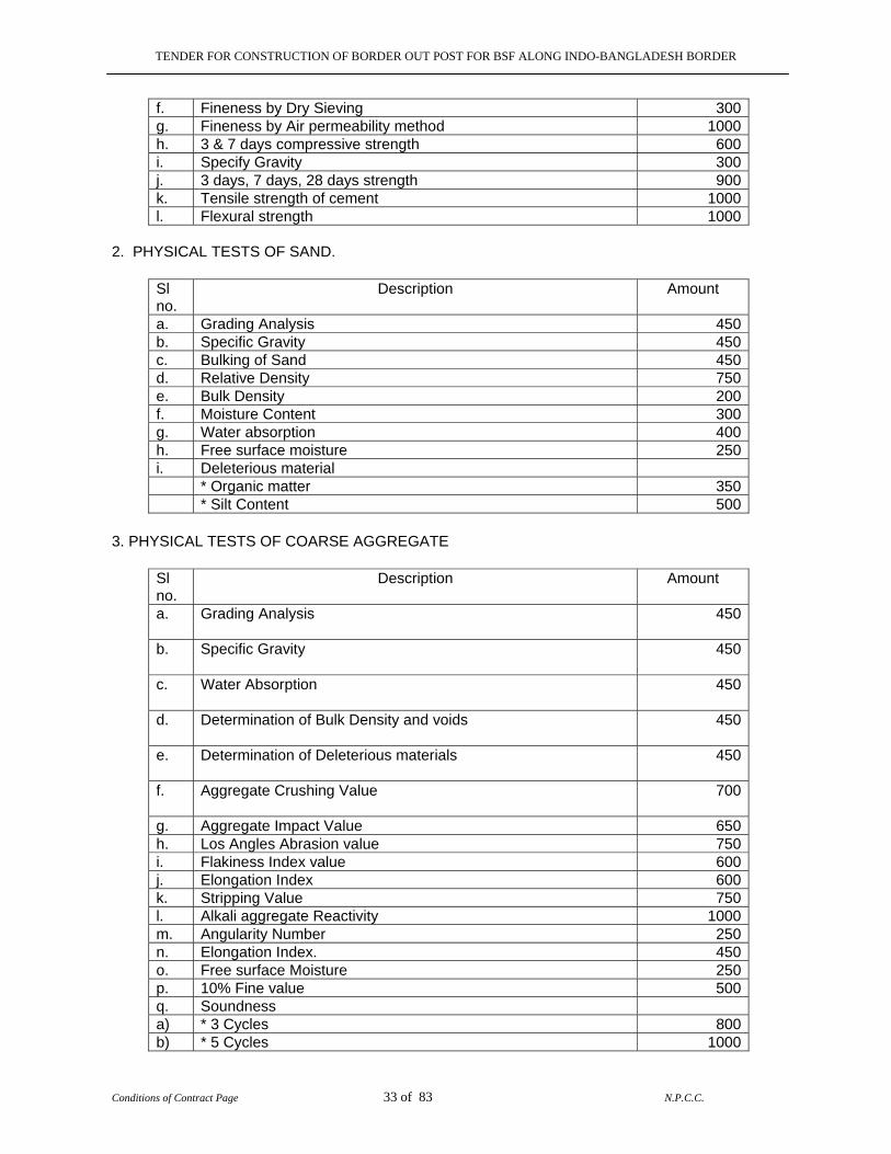
TENDER FOR CONSTRUCTION OF BORDER OUT POST FOR BSF ALONG INDO-BANGLADESH BORDER
Conditions of Contract Page 33 of 83 N.P.C.C.
f. Fineness by Dry Sieving 300g. Fineness by Air permeability method 1000h. 3 & 7 days compressive strength 600i. Specify Gravity 300j. 3 days, 7 days, 28 days strength 900k. Tensile strength of cement 1000l. Flexural strength 1000
2. PHYSICAL TESTS OF SAND.
Sl no.
Description Amount
a. Grading Analysis 450b. Specific Gravity 450c. Bulking of Sand 450d. Relative Density 750e. Bulk Density 200f. Moisture Content 300g. Water absorption 400h. Free surface moisture 250i. Deleterious material * Organic matter 350 * Silt Content 500
3. PHYSICAL TESTS OF COARSE AGGREGATE
Sl no.
Description Amount
a. Grading Analysis
450
b. Specific Gravity
450
c. Water Absorption
450
d. Determination of Bulk Density and voids
450
e. Determination of Deleterious materials
450
f. Aggregate Crushing Value
700
g. Aggregate Impact Value 650h. Los Angles Abrasion value 750i. Flakiness Index value 600j. Elongation Index 600k. Stripping Value 750l. Alkali aggregate Reactivity 1000m. Angularity Number 250n. Elongation Index. 450o. Free surface Moisture 250p. 10% Fine value 500q. Soundness a) * 3 Cycles 800b) * 5 Cycles 1000
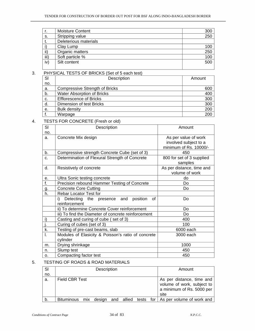
TENDER FOR CONSTRUCTION OF BORDER OUT POST FOR BSF ALONG INDO-BANGLADESH BORDER
Conditions of Contract Page 34 of 83 N.P.C.C.
r. Moisture Content 300s. Stripping value 250t. Deleterious materials i) Clay Lump 100ii) Organic matters 250iii) Soft particle % 100iv) Silt content 500
3. PHYSICAL TESTS OF BRICKS (Set of 5 each test) Sl no.
Description Amount
a. Compressive Strength of Bricks 600b. Water Absorption of Bricks 400c. Efflorescence of Bricks 300d. Dimension of test Bricks 300e. Bulk density 200f. Warpage 200
4. TESTS FOR CONCRETE (Fresh or old)
Sl no.
Description Amount
a. Concrete Mix design As per value of work involved subject to a
minimum of Rs. 10000/- b. Compressive strength Concrete Cube (set of 3) 450 c. Determination of Flexural Strength of Concrete 800 for set of 3 supplied
samples d. Resistively of concrete As per distance, time and
volume of work e. Ultra Sonic testing concrete do f. Precision rebound Hammer Testing of Concrete Do g. Concrete Core Cutting Do h. Rebar Locator Test for i) Detecting the presence and position of
reinforcement Do
ii) To determine Concrete Cover reinforcement Do iii) To find the Diameter of concrete reinforcement Do i) Casting and curing of cube ( set of 3) 400 j. Curing of cubes (set of 3) 100 k. Testing of pre-cast beams, slab 6000 each l. Modules of Elasicity & Poisson’s ratio of concrete
cylinder 3000 each
m. Drying shrinkage 1000 n. Slump test 450 o. Compacting factor test 450
5. TESTING OF ROADS & ROAD MATERIALS
Sl no.
Description Amount
a. Field CBR Test As per distance, time and volume of work, subject to a minimum of Rs. 5000 per site
b. Bituminous mix design and allied tests for As per volume of work and
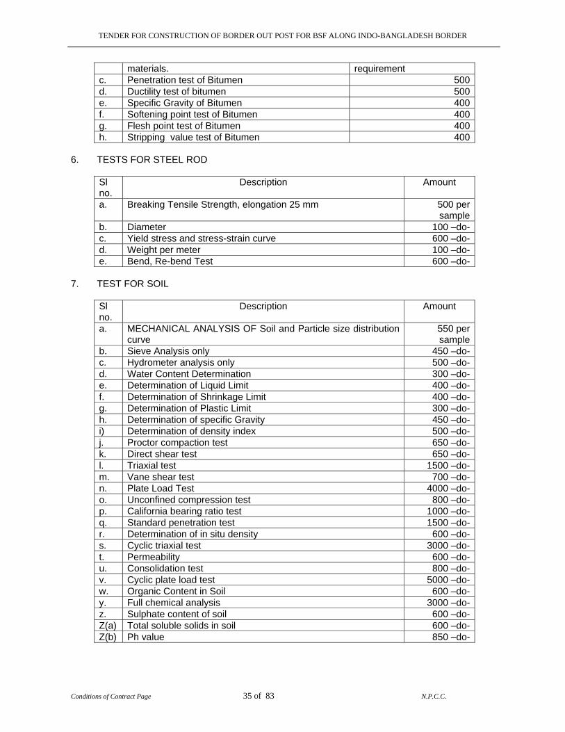
TENDER FOR CONSTRUCTION OF BORDER OUT POST FOR BSF ALONG INDO-BANGLADESH BORDER
Conditions of Contract Page 35 of 83 N.P.C.C.
materials. requirement c. Penetration test of Bitumen 500d. Ductility test of bitumen 500e. Specific Gravity of Bitumen 400f. Softening point test of Bitumen 400g. Flesh point test of Bitumen 400h. Stripping value test of Bitumen 400
6. TESTS FOR STEEL ROD
Sl no.
Description Amount
a. Breaking Tensile Strength, elongation 25 mm 500 per sample
b. Diameter 100 –do-c. Yield stress and stress-strain curve 600 –do-d. Weight per meter 100 –do-e. Bend, Re-bend Test 600 –do-
7. TEST FOR SOIL
Sl no.
Description Amount
a. MECHANICAL ANALYSIS OF Soil and Particle size distribution curve
550 per sample
b. Sieve Analysis only 450 –do-c. Hydrometer analysis only 500 –do-d. Water Content Determination 300 –do-e. Determination of Liquid Limit 400 –do-f. Determination of Shrinkage Limit 400 –do-g. Determination of Plastic Limit 300 –do-h. Determination of specific Gravity 450 –do-i) Determination of density index 500 –do-j. Proctor compaction test 650 –do-k. Direct shear test 650 –do-l. Triaxial test 1500 –do-m. Vane shear test 700 –do-n. Plate Load Test 4000 –do-o. Unconfined compression test 800 –do-p. California bearing ratio test 1000 –do-q. Standard penetration test 1500 –do-r. Determination of in situ density 600 –do-s. Cyclic triaxial test 3000 –do-t. Permeability 600 –do-u. Consolidation test 800 –do-v. Cyclic plate load test 5000 –do-w. Organic Content in Soil 600 –do-y. Full chemical analysis 3000 –do-z. Sulphate content of soil 600 –do-Z(a) Total soluble solids in soil 600 –do-Z(b) Ph value 850 –do-
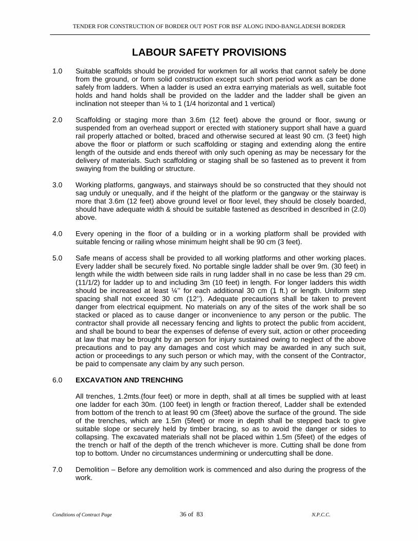
TENDER FOR CONSTRUCTION OF BORDER OUT POST FOR BSF ALONG INDO-BANGLADESH BORDER
Conditions of Contract Page 36 of 83 N.P.C.C.
LABOUR SAFETY PROVISIONS 1.0 Suitable scaffolds should be provided for workmen for all works that cannot safely be done
from the ground, or form solid construction except such short period work as can be done safely from ladders. When a ladder is used an extra earrying materials as well, suitable foot holds and hand holds shall be provided on the ladder and the ladder shall be given an inclination not steeper than ¼ to 1 (1/4 horizontal and 1 vertical)
2.0 Scaffolding or staging more than 3.6m (12 feet) above the ground or floor, swung or
suspended from an overhead support or erected with stationery support shall have a guard rail properly attached or bolted, braced and otherwise secured at least 90 cm. (3 feet) high above the floor or platform or such scaffolding or staging and extending along the entire length of the outside and ends thereof with only such opening as may be necessary for the delivery of materials. Such scaffolding or staging shall be so fastened as to prevent it from swaying from the building or structure.
3.0 Working platforms, gangways, and stairways should be so constructed that they should not
sag unduly or unequally, and if the height of the platform or the gangway or the stairway is more that 3.6m (12 feet) above ground level or floor level, they should be closely boarded, should have adequate width & should be suitable fastened as described in described in (2.0) above.
4.0 Every opening in the floor of a building or in a working platform shall be provided with
suitable fencing or railing whose minimum height shall be 90 cm (3 feet). 5.0 Safe means of access shall be provided to all working platforms and other working places.
Every ladder shall be securely fixed. No portable single ladder shall be over 9m. (30 feet) in length while the width between side rails in rung ladder shall in no case be less than 29 cm. (11/1/2) for ladder up to and including 3m (10 feet) in length. For longer ladders this width should be increased at least ¼’’ for each additional 30 cm (1 ft.) or length. Uniform step spacing shall not exceed 30 cm (12’’). Adequate precautions shall be taken to prevent danger from electrical equipment. No materials on any of the sites of the work shall be so stacked or placed as to cause danger or inconvenience to any person or the public. The contractor shall provide all necessary fencing and lights to protect the public from accident, and shall be bound to bear the expenses of defense of every suit, action or other proceeding at law that may be brought by an person for injury sustained owing to neglect of the above precautions and to pay any damages and cost which may be awarded in any such suit, action or proceedings to any such person or which may, with the consent of the Contractor, be paid to compensate any claim by any such person.
6.0 EXCAVATION AND TRENCHING
All trenches, 1.2mts.(four feet) or more in depth, shall at all times be supplied with at least one ladder for each 30m. (100 feet) in length or fraction thereof, Ladder shall be extended from bottom of the trench to at least 90 cm (3feet) above the surface of the ground. The side of the trenches, which are 1.5m (5feet) or more in depth shall be stepped back to give suitable slope or securely held by timber bracing, so as to avoid the danger or sides to collapsing. The excavated materials shall not be placed within 1.5m (5feet) of the edges of the trench or half of the depth of the trench whichever is more. Cutting shall be done from top to bottom. Under no circumstances undermining or undercutting shall be done.
7.0 Demolition – Before any demolition work is commenced and also during the progress of the work.

TENDER FOR CONSTRUCTION OF BORDER OUT POST FOR BSF ALONG INDO-BANGLADESH BORDER
Conditions of Contract Page 37 of 83 N.P.C.C.
7.1 All roads and open areas adjacent to the work site shall either be closed or suitably protected.
7.2 No electric cable or apparatus, which is likely to be a source of danger or a cable or
apparatus used by the operator shall remain electrically, charged. 7.3 All practical steps shall be taken to prevent danger to persons employed from risk or fire
or explosion or flooding. No floor, roof or other part of the building shall be overloaded with debris or materials as to render it unsafe.
8.0 All necessary personal safety equipments as considered adequate by the Engineer-In-
Charge/Zonal Manager should be kept available for the use of persons employed on the site and maintained in a condition suitable for immediate use, and the contractor should take adequate step to ensure proper use of equipment by those concerned. The following safety equipment shall be invariably provided.
8.1 Workers employed on mixing asphaltic materials, cement and lime mortars shall be provided
with footwear and protective goggles. 8.2 Those engaged in white washing and mixing or stacking of cement bags or any materials
which is injurious to the eye shall be provided with protective goggles. 8.3 Those engaged in welding works shall be provided with welders protective eye shields. 8.4 Stone breakers shall be provided with protective goggles and protective clothing and seated
at sufficiently safe interval. 8.5 When workers are employed in sewers and manholes, which are in active use, the
Contractors shall ensure that the manhole covers are opened and ventilated at least for an hour before the workers are allowed to get into the manholes, and the manholes so opened shall be cordoned off with suitable railing and provided with warning or boards to prevent accident the public. In addition, the contractor shall ensure that the following safety measures are adhered to:
a. Entry for workers into the line shall not be allowed except under supervision of the JE or any
other higher officer. b. At least 5 to 6 manholes upstream and down stream should be kept open for at least 2 to 3
hours before any man is allowed to enter into the manholes for working inside. c. Before entry presence of Toxic gases should be tested by inserting wet lead acetate paper
which changes colour in the presence of such gases and gives indication of their presence. d. Presence of Oxygen should be verified by lowering a detector lamp into the manhole. In
case, no Oxygen is found inside the sewer line, workers should be sent only with Oxygen kit. e. Safety belt with rope should be provided to the workers. While working inside the manholes
such rope should be handled by two men standing outside to enable him to be pulled out during emergency.
f. The area should be barricaded or cordoned of by suitable means to avoid mishaps of any
kind. Proper warning signs should be displayed for the safety of the public whenever cleaning works are undertaken during night or day.
g. No smoking or open flame shall be allowed near the block manhole being cleaned.
TENDER FOR CONSTRUCTION OF BORDER OUT POST FOR BSF ALONG INDO-BANGLADESH BORDER
Conditions of Contract Page 38 of 83 N.P.C.C.
h. The malba obtained on account of cleaning of blocked manholes and sewer lines should be immediately removed to avoid accidents on account of slippery nature of the malba.
i. Workers should not be allowed to work inside the manhole continuously. He should be given
rest intermittently. The Engineer In-charge may decide the time up to which a worker may be allowed to work continuously inside the manhole.
j. Gas masks with Oxygen Cylinder should be kept at site for use in emergency. k. Air-blowers should bed used for flow of fresh air through the manholes. Whenever called for,
portable air-blowers are recommended for ventilating the manholes. The Motors for these shall be vapour proof and of totally enclosed type. Non sparking gas engines also could be used but they should be placed at-least 2 meters away from the opening and on the leeward side protected from wind so that they will not be a source of friction on any inflammable gas that might be present.
l. The workers engaged for cleaning the manholes/sewers should be properly trained before
allowing to work in the manhole. m. The workers shall be provided with Gumboots or non sparking shoes, bump helmets and
gloves non sparking tools, safety lights and gas masks and portable air blowers (when necessary). They must be supplied with barrier cream for anointing the limbs before working inside the sewer lines.
n. Workmen descending a manhole shall try each ladder step or rung carefully before putting
his full weight on it to guard against insecure fastening due to corrosion of the rung fixed to manhole well.
o. If a man has received a physical injury, he should be brought out of the sewer immediately
and adequate medical aid should be provided to him. p. The extent to which these precautions are to be taken depend on individual situation but the
decision of the Engineer In-charge regarding the steps to be taken in this regard in an individual case will be final.
8.6 The Contractor shall not employ men and women below the age of 18 years on the work of
painting with products containing lead in any form wherever men above the age of 18 are employed on the work of lead painting the following precautions should be taken.
8.6.1 No paint containing lead or lead products shall be used except in the form of paste or
readymade paint. 8.6.2 Suitable face masks should be supplied for use by the workers when paint is applied in the
form of spray or a surface having lead paint is dry rubbed and scrapped. 8.6.2 Overalls shall be supplied by the Contractor to the workmen and adequate facilities 8.6.4.1 a) White lead sulphate or lead work products containing those pigments shall not be
used in painting operation except in the form of paste or of paints ready for use.
b) Measures shall be taken whenever required in order to prevent danger arising from the application of paint in the form of spray.
c) Measures shall be taken, whenever practicable to prevent danger arising out of dust
caused by dry rubbing down and scrapping.
TENDER FOR CONSTRUCTION OF BORDER OUT POST FOR BSF ALONG INDO-BANGLADESH BORDER
Conditions of Contract Page 39 of 83 N.P.C.C.
8.6.4.2 a) Adequate facilities shall be provided to enable working painter to wash during and on cessation of work.
b) Suitable arrangements shall be made to prevent clothing put off during working hours being spoiled by painting materials.
8.6.4.3 a) Cases of lead poisoning and of suspected lead poisoning shall be notified and shall be subsequently verified by a medical man appointed by the competent authorities of the Consultant.
b) The NPCC may require when necessary a medical examination of workers.
c) Instructions with regard to the special hygienic precautions to be taken in the painting trade shall be distributed to working painters.
9.0 When the work is done near any place where there is risk of drowning, all necessary equipment’s should be provided and kept ready for use and all necessary steps taken for prompt rescue of any person in danger and adequate provisions should be made for prompt first aid treatment of all injuries likely to be obtained during the course of the work.
10.0 Use of hoisting machines and tackle including their attachment encourage and supports
shall conform to the following standard of conditions 10.1 a) These shall be of good mechanical construction, sound material and adequate
strength and free from patent, defects and shall be kept required in good working order.
b) Every rope used in hoisting or lowering materials or as a means of suspension shall be of durable quality and adequate strength, and free from patent defects.
10.2 Every crane driver or hoisting appliance operator shall be properly qualified and no person
under the age of 21 years should be in-charge of any hoisting machine including any scaffolding, which or giving signals to operator.
10.3 In case of every hoisting machine and of every chain ring hook, shackle swivel and pulley
block used in hoisting or as means of suspension the safe working load shall be ascertained by adequate means. Every hoisting machine and all gear referred to above shall be plainly marked with the safe working load. In case of a hoisting machine having a variable safe working load, each safe working load and the conditions under which it is applicable shall be clearly indicated. No part of any machine or any gear referred to above in this paragraph shall be loaded beyond the safe working load except for the purpose of testing.
10.4 In case of NPCC machines, the safe working load shall be notified by the Engineer-In-
Charge/Zonal Manager. As regards Contractor’s machines the Contractor shall notify the safe working load of the machine to the Engineer-In-Charge/Zonal Manager whenever he brings any machinery to site of work and get verified by the Engineer-In-Charge/Zonal Manager.
11.0 Motors gearing, transmission electric wiring and other dangerous parts of hoisting
appliances should be provided with efficient safeguard, hoisting appliances should be provided with such means as will reduce to the minimum the risk of accidental descent of the load. Adequate precautions should be taken to reduce the minimum the risk of any part of a suspended load becoming accidentally displaced. When workers are employed on electrical installations, which are already energized, insulating mats, wearing apparel, such as gloves sleeves and boots as may be necessary be provided. The worker should not wear any rings, watches and carry keys or other materials, which are good conductors of electricity.
TENDER FOR CONSTRUCTION OF BORDER OUT POST FOR BSF ALONG INDO-BANGLADESH BORDER
Conditions of Contract Page 40 of 83 N.P.C.C.
12.0 All scaffold, ladders, and other safety devices mentioned or described herein shall be maintained in safe condition and no scaffold ladder or equipment shall be altered or removed while it is in use. Adequate washing facilities should be provided at or near places of work.
13.0 These safety provisions should be brought to the notice of all concerned by display on a
notice board at a prominent place of work spot. The person responsible for compliance of the safety codes shall be named therein by the contractor.
14.0 To ensure effective enforcement of the rules and regulations relating to safety precautions
the arrangements made by the contractor shall be open to inspection by the or their representatives.
15.0 Notwithstanding the above clauses from (i) to (xiv) there is nothing in these to exempt the
contractor from the operations of any other Act or Rule on force in the Republic of India.
TENDER FOR CONSTRUCTION OF BORDER OUT POST FOR BSF ALONG INDO-BANGLADESH BORDER
Conditions of Contract Page 41 of 83 N.P.C.C.
MODEL RULES FOR THE PROTECTION OF HEALTH AND SANITARY ARRANGEMENTS FOR WORKERS
1.0 APPLICATION
These rules shall apply to all building and construction works in which 20 (twenty) or more workers are ordinarily employed or are proposed to be employed in any day during which the contractor work is in progress.
2.0 DEFINITION
Work place means a place where twenty or more workers are ordinarily employed or are proposed to be employed in connection with construction work on any day during the period which the contract work is in progress.
3.0 FIRST-AID FACILITIES 3.1 At every work place first aid facilities shall be provide and maintained, so as to be easily
accessible during working hours, First-Aid boxes at the rate of not less than one box per 150 contract labour or part thereof ordinarily employed.
3.2 The First-Aid box shall be distinctly marked with a red cross on white ground and shall
contain the following equipments: - 3.2.1a) For work places in which number of contract labour employed does not exceed 50, Each
First-Aid box shall contain the following equipments:
i) 6 small sterilized dressings.
ii) 3 medium size sterilized dressings.
iii) 3 large size sterilized dressings.
iv) 3 large sterilized burn dressings.
v) 1 (30 ml) bottle containing a two percent alcoholic solution of iodine.
vi) 1 (30 ml) bottle containing salvolatile having the does and mode of administration indicated on the label.
vii) 1 snake-bite lancet.
viii) 1 (30 gms) bottle of potassium permanganate crystals.
ix) 1 pair of scissors.
x) 1 copy of the First-Aid leaf-let issued by the Director General, Factory Advise
Service & Labour Institutes, Government of India.
xi) 1 bottle containing 100 tablets (each of 5 grams) of aspirin.
xii) Ointment for burns
xiii) A bottle of suitable surgical antiseptic solution.
TENDER FOR CONSTRUCTION OF BORDER OUT POST FOR BSF ALONG INDO-BANGLADESH BORDER
Conditions of Contract Page 42 of 83 N.P.C.C.
3.2.2 For work places in which the number of contract labour exceed 50. Each First-Aid
box shall contain the following equipments.
i) 12 small sterilized dressings.
ii) 6 medium size sterilized dressings.
iii) 6 large size sterilized burn dressings.
iv) 6 large size sterilized burn dressings.
v) 6 (15 gms) packet sterilized cotton wool.
vi) 1 (60 ml.) bottle containing a two percent iodine alcoholic solution.
vii) 1 (60 ml.) bottle containing salvolatile having the dose and mode of administration indicated on the label.
viii) 1 roll of adhesive plaster.
ix) 1 snake-bite lancet.
x) 1 (30 gms.) bottle of potassium permanganate crystals.
xi) 1 pair of scissors.
xii) 1 copy of the First-Aid leaf-let issued by the Director General, Factory Advice
Service and Labour Institutes, Government of India.
xiii) A bottle containing 100 tablets (each of 5 grams) of aspirin.
xiv) Ointment for burns.
xv) A bottle of suitable surgical antiseptic solution. 3.3 Adequate arrangements shall be made for immediate recoupment of the equipment when
necessary. 3.4 Nothing except the prescribed contents shall be kept in the First Aid box. 3.5 The First Aid box shall be kept in charge of a responsible person who shall always be readily
available during the working hours of the work place. 3.6 A person in charge of the First-Aid box shall be a person trained in First-Aid treatment, in
work places where the number of labour employed is 150 or more. 3.7 In work places where the number of labour employed is 500 or more and hospital facilities
are not available within easy distance of the works, first-Aid Posts shall be established and run by a trained Compounder. The Compounder shall be on duty and shall be available at all hours when the workers are at work.
3.8 Where work places are situated in places which are not towns of cities a suitable motor
transport shall be kept readily available to carry injured person or suddenly taken ill to the nearest hospital.
TENDER FOR CONSTRUCTION OF BORDER OUT POST FOR BSF ALONG INDO-BANGLADESH BORDER
Conditions of Contract Page 43 of 83 N.P.C.C.
4.0 DRINKING WATER 4.1 In every work place, there shall be provided and maintained at suitable places, easily
accessible to labour, a sufficient supply of cold water fit for drinking. 4.2 Where drinking water is obtained from an intermittent public water supply, each work place
shall be provided with storage where such drinking water shall be stored. 4.3 Every water supply of storage shall be at a distance of not less than 50 feet from any latrines
drain or other source of pollution, Where water has to be drawn from an existing well which is within such proximity of latrine, drain or any other source of pollution, the well shall be properly chlorinated before water is drawn from it for drinking. All such wells shall be entirely closed in and be provided with a trap-door which shall be dust and water-proof.
4.4 A reliable pump shall be fitted to each covered well, trap-door shall be kept locked and
opened only for cleaning or inspection which shall be done at least once a month. 5.0 WASHING FACILITIES 5.1 In every work place adequate and suitable facilities for washing shall be provided and maintained for the use of labour employed herein. 5.2 Separate and adequate screening facilities shall be provided for the use of male and female
workers. 5.3 Such facilities shall be conveniently accessible and shall be kept clean and hygienic
condition. 6.0 LATRINES AND URINALS 6.1 Latrines shall be provided in every work place on the following scale, namely: a) Where females are employed there shall be at least one latrine for every 25 females. b) Where males are employed, there shall be at least one latrine for every 25 males. Provided that where the number of males or females exceeds 100, it shall be sufficient if
there is one latrine for 25 males or females, as the case may be up to the first 100, and one for every 50 thereafter.
6.2 Every latrine shall be under cover and so partitioned off as to secure privacy and shall has a
proper door and fastenings. 6.3 Construction of Latrines: The inside walls shall be constructed of masonry or some suitable
heat resisting non-absorbent materials and shall be cement washed inside and outside at least once a year. Latrine shall not be a standard lower than bore-hole system.
6.4 (a) Where workers of both sexes are employed, there shall be displayed outside each
block of latrine and urinal, a notice in the, language understood by the majority of the workers “For Men only” For Women only” as the case may be
(b) The notice shall also bear the figure of man or of a women, as the case may be 6.5 There shall be at least one urinal for male workers up to 50 and one for female workers up to
50 employed at a time. Provided that where the number of male or female workmen, as the case may be, exceeds 500, it shall be sufficient if there is one urinal for every 50 males or females up to the first 500 and one for every 100 or part thereof, thereafter.
TENDER FOR CONSTRUCTION OF BORDER OUT POST FOR BSF ALONG INDO-BANGLADESH BORDER
Conditions of Contract Page 44 of 83 N.P.C.C.
6.6 a) The latrines and urinals shall be adequately lighted and shall be maintained in a clean and sanitary condition at all times.
b) Latrines and urinals other than those connected with a flush sewerage system shall comply with
the requirements of the Public Health authorities. 6.7 Water shall be provided by means of a tap or otherwise so as to be conveniently accessible
in or near the latrines and urinals 6.8 DISPOSAL OF EXCRETA Unless otherwise arrange for by the local sanitary authority arrangements for proper disposal
of excreta by incineration at the work place shall be made by means of a suitable incineration. Alternatively excreta may be disposed off by putting a layer of night soil at the bottom of a pucca tank prepared for the purpose and covering it with a 15 cm layer of waste or for refuse and then covering it with a layer of earth for fortnight (when it will turn into manure).
6.9 The Contractor shall, at his own expense, carry out all instruction issued to him by the
Engineer-In-Charge/Zonal Manager to effect proper disposal of night soil and other conservancy work in respect of the contractor’s workmen or employees on the site. The Contractor shall be responsible for payment Authority for execution of such work on his behalf.
7.0 PROVISION OF SHELTER DURING REST At every place there shall be provided, free of cost four suitable sheds, two for males and the
other two for rest separately for the use of man and women labour The height of each shelter shall not be less than 3 meters from the floor level to the lowest part of the roof These shall be kept clean and the space provided shall be on the basis of 0.6 sqm. per head.
Provided that the Engineer-In-Charge/Zonal Manager may permit, subject to his satisfaction,
a portion of the building under construction or other alternative accommodation to be use for the purpose.
8.0 CRECHES 8.1 A every work place, at which 20 or more women workers are ordinarily employed, there shall
be provided two rooms or reasonable dimensions for the use of their children under the age of six years. One room shall be used as a play room for the children and the other as their bedrooms.
The rooms shall be constructed on standard not lower than the following: i) thatched roof ii) mud floor and walls iii) planks spread over the mud floor and covered with matting 8.2 The rooms shall be provided with suitable and sufficient openings for light and ventilation
thee shall be adequate provision of sweepers to keep the places clean. 8.3 The Contractor shall supply adequate number of toys and games in the playroom and
sufficient number of cots and beddings in the bed-room
TENDER FOR CONSTRUCTION OF BORDER OUT POST FOR BSF ALONG INDO-BANGLADESH BORDER
Conditions of Contract Page 45 of 83 N.P.C.C.
8.4 The Contractor shall provide one Ayah to look after the children in the crèche when the
number of women workers does not exceed 50 and two when the number of women workers exceed 50.
8.5 The use of the rooms/earmarked as crèches shall be restricted to children, their attendant
and mother of the children, 9.0 CANTEENS 9.1 In every work place where the work regarding the employment of contract labour is likely to
continue for six months and wherein contract labour numbering one hundred or more are ordinarily employed, and adequate canteen shall be provided by the Contractor for the use of such labour.
9.2 The canteen shall be maintained by the Contractor in an efficient manner. 9.3. The canteen shall consist of at least a dining hall, kitchen, storeroom, pantry and washing
places separately for workers and utensils. 9.4. The canteen shall be sufficiently lighted at all times when any person has access to it 9.5 The floor shall be made of smooth and impervious material and inside walls shall be lime
washed or colour washed at least once in each year. Provided that the inside walls of the kitchen shall be lime-washed every four months 9.6 The premises of the canteen shall be maintained in a clean and sanitary condition 9.7 Waste Water shall be carried away in suitable covered drains and shall not be allowed to
accumulate so as to cause a nuisance. 9.8 Suitable arrangements shall be made for the collection and disposal of garbage 9.9 The dinning hall shall accommodate at a time 30 persons of the labour working at time
9.10 The floor area of the dinning hall, excluding the area occupied by the service counter and
any furniture except tables and chair shall not be less than one square meter per dinner to be accommodated.
9.11 A) A portion of the dinning hall, and service counter shall be partitioned off and reserved for
women workers in proportion to their number. B) Washing places for women shall be separate and screened to secure privacy 9.12 Sufficient tables stool, chairs or benches shall be available for the number of dinners to be
accommodated 9.13.1 a) There shall be provided and maintained sufficient utensils, crockery, furniture and any
other equipment necessary for the efficient running of the canteen. b) The furniture, utensils and other equipment shall be maintained in a clean and hygienic
condition 9.13.2 a) Suitable clean clothes or the employees serving in the canteen shall be provided and
maintained. b) a service counter, if provided, shall have top of smooth and impervious material. c) Suitable facilities including and adequate supply of hot water shall be provided for the
cleaning of utensils and equipment.
TENDER FOR CONSTRUCTION OF BORDER OUT POST FOR BSF ALONG INDO-BANGLADESH BORDER
Conditions of Contract Page 46 of 83 N.P.C.C.
9.14 The food stuffs and other items to be served in the canteen shall be in conformity with the
normal habits of the labour. 9.15 The charge for food stuffs, beverages and any other items served in the canteen shall be
based on ‘No profit’ No loss’ and shall be conspicuously displayed in the canteen 9.16 In arriving at price of Good stuffs, and other articles served in the canteen, the following
items shall not be taken into consideration as expenditure, namely :
a) The rent of land building b) The depreciation and maintenance charges for the building and equipment provided
for the canteen. c) the cost of purchase, repair and replacement of equipment including furniture,
crockery, cutlery and utensils: d) The water charges and other charges incurred for lighting and ventilation e) The interest and amounts spent on the provision and maintenance and equipment
provide for in the canteen.
9.17 The accounts pertaining to the canteen shall be audited once every 12 months by registered
accountants and auditors. 10.0 ANTIMALARIAL PRECAUTIONS The Contractors shall at his own expense conform to all anti-malarial instructions given to
him by the Engineer-In-Charge/Zonal Manager including the filling up of any borrows pits which may have been dug by him.
11.0 AMMENDMENTS NPCC may from time to time, add to or amend these rules and issue such directions as it
may consider necessary for the purpose of removing any difficulty which may arise in the administration hereof.
TENDER FOR CONSTRUCTION OF BORDER OUT POST FOR BSF ALONG INDO-BANGLADESH BORDER
Conditions of Contract Page 47 of 83 N.P.C.C.
CONTRACTOR’S LABOUR REGULATIONS 1.0 SHORT TITLE These regulations may be called the Contractor “Labour Regulations” 2.0 Definitions 2.1 “Workman” means any person employed by the NPCC or its Contractor directly or indirectly
through a sub-contractor, with or without the knowledge, of the NPCC to do any skilled, semi-skilled, un-skilled, manual, supervisory, technical or clerical work for hire or reward, whether, the terms of employment are expressed or implied but does not include any person-
a) Who is employed mainly in a managerial or administrative capacity; or b) Who being employed in a supervisory capacity draws wages exceeding Rupees Two
thousand Five hundred per person or exercises either by the nature of the duties attached to the office or by reason of powers vested to him, functions mainly of managerial nature.
c) Who is an out worker, that is to say, a person to whom any articles or materials are given
out by or on behalf of the principal employer to be made up cleaned, washed, altered, ornamental finished, repaired, adopted or otherwise processed for sale for the purpose of the trade or business of the principal employer and the process is to be carried out either in the home of the out worker or in some other premises, not being premises under the control and management of the principals employer.
2.2 “Fair Wages” means wages whether for time or piece work fixed and notified under the
provisions of the minimum Wages Act from time to time. 2.3 “Contractor” shall include every person who undertake to produce a given result other than a
mere supply of goods or articles of manufacture through labour or who supplies labour for any work and includes a sub-contractor.
2.4 “Wages” shall have the same meaning as defined in the Payment of Wages act. 2.4.1 Normally working hours of an adult employee should not exceed 9 hours a day, The working
day shall be so arranged that inclusive of interval for rest, if any, it shall not spread over more than 12 hours on any day.
2.4.2 When an adult worker is made to work for more than 9 hours on any day or for more than 48
hours in any week he shall be paid overtime for the extra hours put in by him at double the ordinary rate of wages.
2.4.3.1 Every worker shall be given a weekly holiday on a Sunday, in accordance with the provisions
of the Minimum Wages (Central) Rules on a Sunday, in accordance with the provisions of the Minimum Wages (Central) Rules 1960 as amended from time to time, irrespective of whether such worker is governed by the Minimum Wages Act or not.
2.4.3.2 Whether the Minimum Wages prescribed by the Government under the Minimum Wages Act
are not inclusive of the wages for the weekly day of rest, the worker shall be entitled to rest day wages at the rate applicable to the next preceding day, provided he has worked under the same contractor for a continuous period of not less than 6 days.
TENDER FOR CONSTRUCTION OF BORDER OUT POST FOR BSF ALONG INDO-BANGLADESH BORDER
Conditions of Contract Page 48 of 83 N.P.C.C.
2.4.3.3 here a contractor is permitted by the Engineer-In-Charge/Zonal Manager to allow a worker to work on a normal weekly holiday, he shall grant a substitute holiday to him for the whole day on one of the five days immediately before or after the normal weekly holidays and pay wages to such worker for the work performed on the normal weekly holiday at overtime rate.
3.0 DISPLAY OF NOTICE REGARDING-WAGES, ETC.
The contractor shall before he commences his work on contract, display and correctly maintain and continue to display and correctly maintain in a clean and legible condition in conspicuous places on the work., notices in English and in the local Indian languages spoken by the majority of the workers, giving the minimum rates of wages fixed under the Minimum Wages Act, the actual wage period, being paid, the hours of work for which such wages are earned, wage period, dates of payment of wages and other relevant information as per Appendix ‘A’
4.0 PAYMENT OF WAGES 4.1 The contractor shall fix wage periods in respect of which wages shall be payable 4.2 No wage period shall exceed one month. 4.3 The wages of every person employed as labour in an establishment or by a contractor where
less than one thousand, such persons are employed shall be paid before the expiry of the seventh day and in other cases before the expiry of tenth day after the last day of the wage period in respect of which the wages are payable.
4.4 Where the employment of any worker is terminated by or on behalf of the contractor the
wages earned by him shall be paid before the expiry of the second working day from the date on which his employment I terminated.
4.5 All payments of wages shall be made on a working. Day at the work premises and during the
working time and on a date notified in advance and in case the work is completed before the expiry of the wage period, final payment shall be made within 48 hours of the last working day.
4.6 Wages due to every worker shall be paid to him direct or to other person authorized by him
in this behalf. 4.7 All wages shall be paid in current coin or currency or in both. 4.8 Wages shall be paid without any deduction of any kind except those specified by the Central
Government by general or special order in this behalf or permissible under the payment of Wages Act 1956.
4.9 A notice showing the wage period and the place and time of disbursement of wages shall be
displayed at the place of work and a copy sent by the contractor to the Engineer-In-Charge/Zonal Manager under acknowledgment.
4.10 It shall be the duty of the contractor to ensure the disbursement of wages in the presence of
the Engineer or any other authorized representatives of the Engineer-In-Charge/Zonal Manager who will be required to be present at the place and time of disbursement of wages by the contractor to workmen.
TENDER FOR CONSTRUCTION OF BORDER OUT POST FOR BSF ALONG INDO-BANGLADESH BORDER
Conditions of Contract Page 49 of 83 N.P.C.C.
4.11 The contractor shall obtain from the Engineer or any other authorized representative of the Engineer-In-Charge/Zonal Manager as the case may be, a certificate under his signature at the end of the entries in the “Register of Wages” or the “Wages-cum-Muster Roll” as the case may be in the following form.
“Certified that the amount show in column No………..has been paid to the workmen
concerned in my presence on…………..at……………” 5.0 FINES AND DEDUCTIONS, WHICH MAY BE MADE FROM WAGES 5.1 The wages of a worker shall be paid to him without any deduction of any kind except the
following - FINES a) Deductions for absence from duty i.e. from the place or the places where by the terms of his
employment he is required to work. The amount of deduction shall be in proportion to the period for which he was absent
b) Deduction for damage to or loss of goods expressly entrusted to the employed persons
for custody, or from loss of money or any other deduction which he is required to account where such damage or loss is directly attributable to his neglect or default.
c) Deduction for recovery of advances or for adjustment of over payment of wages,
advances granted shall be entered in a register. d) Any other deduction, which the Central Government may from time to time allow. 5.2 No fines should be imposed on any worker save in respect of such acts and omissions on
his part as have been approved by the Chief Labour Commissioner. NOTE : An approved list of Acts and Omissions for which fines can be imposed is enclosed
at Appendix-I 5.3 No fine shall be imposed on a worker and no deduction for damage or loss shall be made
from his wages until the worker has been given and opportunity of showing cause against such fines or deductions.
5.4 The total amount of fine which may bed imposed in any one wage period on a worker shall
not exceed an amount equal to there paisa in a Rupees of the total wages, payable to him in respect of that wage period.
5.5 No fine imposed on any worker shall be recovered from him in installment, or after the expiry
of sixty days from the date on which it was imposed, 5.6 Every fine shall be deemed to have been imposed on the day of the act or omission in
respect of which it was imposed. 6.0 LABOUR RECORDS 6.1 The contractor shall maintain a “Register of person employed” on work on contract in form
XIII of the CL (R7A) Central Rules 1971 (Appendix-B). 6.2 The Contractor shall maintain a “Muster Roll” register in respect of all workmen employed by
him on the work under contract in from XVI of the CL (R&A) Rules 1971 (Appendix-C).
TENDER FOR CONSTRUCTION OF BORDER OUT POST FOR BSF ALONG INDO-BANGLADESH BORDER
Conditions of Contract Page 50 of 83 N.P.C.C.
6.3 The contractor shall maintain a “Wage Register” in respect of all workmen employment by him on the work in form (Appendix-D).
6.4 Register of accidents – the contractor shall maintain a register of accidents in such form as may be convenient at the work place but the same shall include the following particulars :
a) Full particulars of the laborers who met with accident.
b) Rate of wages
c) Sex
d) Age
e) Nature of accident and cause of accident.
f) Time and date of accident.
g) Date and time when he/she admitted in Hospital
h) Date of discharge from the Hospital
i) Period of treatment and result of treatment
j) Percentage of loss of earning capacity and disability as assessed by Medical
Officer.
k) Claim required to be paid under Workmen’s Compensation Act.
l) Date of payment of compensation
m) Amount paid with details of the person to whom the same was paid
n) Authority by whom the compensation was assessed.
o) Remarks
6.5 Register of Fines-The contractor shall maintain a “Register of Fines” in the from(Appendix-H) The contractor shall display in a good condition and in a conspicuous place of work the
approved list of Acts and Omission for which fines can be imposed (Appendix-I) 6.6 Register of Deductions-The contractor shall maintain a “Register of Deductions” for damage
or loss in form (Appendix-J) 6.7 Register of Advances-The contractor shall maintain a “Register of Advances” in form
(Appendix-K). 6.8 Register of Overtime-The contractor shall maintain a “Register of Overtime” in form
(Appendix-L). 7.0 ATTENDANCE CARD CUM WGE SLIP: 7.1 The contractor should use a attendance card-cum-wage slip to each workman employed by
him in the specimen form at (Appendix-E). 7.2 The card shall be valid for each wage period. 7.3 The contractor shall mark the attendance of each workman on the card which each day,
once at the commencement of the day and again after the rest interval. Before he actually starts work.
TENDER FOR CONSTRUCTION OF BORDER OUT POST FOR BSF ALONG INDO-BANGLADESH BORDER
Conditions of Contract Page 51 of 83 N.P.C.C.
7.4 The card shall remain in possession of the worker during the wage period under reference. 7.5 The contractor shall complete the wage slip potion on the reverse of the card at least a day
prior to the disbursement of wages in respect of the wage period under reference. 7.6 The contractor shall obtain the signature or thump impression of the worker on the wage slip
at the time of disbursement of wages and retain the card with him. 8.0 EMPLOYMENT CARD The contractor shall issue and Employment Card in form to each worker within three days of
the employment if the worker (Appendix-F). 9.0 SERVICE CERTIFICATE On termination of employment for any reason whatsoever the contractor shall issue to the
workman whose services have been terminated, a service certificate in from Appendix-G 10.0 PRESERVATION OF LABOUR RECORDS All records required to be maintained under Regulation Nos.6 and 7 shall be preserved in
original for a period of three years from the date of last entries made in them and shall be made available for inspection by the Engineer-In-Charge/Zonal Manager, Labour Officer.
11.0 POWER OF LABOUR OFFICERS TO MAKE INVESTIGATIONS INQUIRY The Labour Officer or any other person authorized by NPCC on its behalf shall have power
to make inquires with a view to ascertaining and enforcing due and proper observance of the Fair Wage Clauses and the Provisions of Regulations. He shall investigate into any complaint regarding the default made by the contractor or sub-contractor in regard to such provision.
12.0 Inspection of Book and slips The contractor shall allow inspection of all the prescribed labour records to any of his
workers or to his agent at a convenient time and place after due notice is received or to the labour officer or any other person, authorized by the Central Government on his behalf
13.0 SUBMISSION OF RETURNS The contractor shall submit periodical returns as may be specified form time to time. 14.0 AMENDMENTS
The NPCC may form to time, add or amend the regulations and on any question as to the application, interpretation or effect of these regulations the decision of the Zonal Chief concerned shall be final.
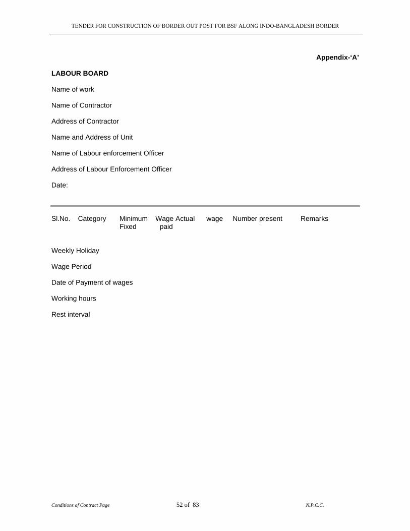
TENDER FOR CONSTRUCTION OF BORDER OUT POST FOR BSF ALONG INDO-BANGLADESH BORDER
Conditions of Contract Page 52 of 83 N.P.C.C.
Appendix-‘A’
LABOUR BOARD Name of work Name of Contractor Address of Contractor Name and Address of Unit Name of Labour enforcement Officer Address of Labour Enforcement Officer Date: Sl.No. Category Minimum Wage Actual wage Number present Remarks Fixed paid Weekly Holiday Wage Period Date of Payment of wages Working hours Rest interval
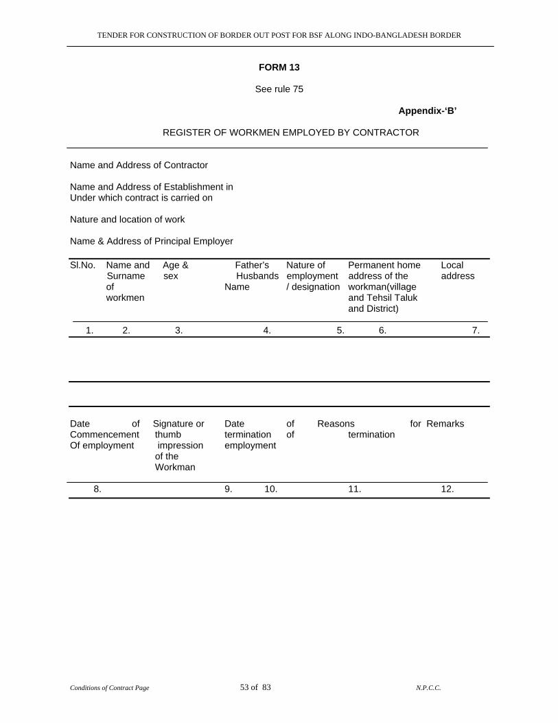
TENDER FOR CONSTRUCTION OF BORDER OUT POST FOR BSF ALONG INDO-BANGLADESH BORDER
Conditions of Contract Page 53 of 83 N.P.C.C.
FORM 13
See rule 75 Appendix-‘B’ REGISTER OF WORKMEN EMPLOYED BY CONTRACTOR Name and Address of Contractor Name and Address of Establishment in Under which contract is carried on Nature and location of work Name & Address of Principal Employer Sl.No. Name and Age & Father’s Nature of Permanent home Local Surname sex Husbands employment address of the address of Name / designation workman(village workmen and Tehsil Taluk and District)
1. 2. 3. 4. 5. 6. 7. Date of Signature or Date of Reasons for Remarks Commencement thumb termination of termination Of employment impression employment of the Workman 8. 9. 10. 11. 12.
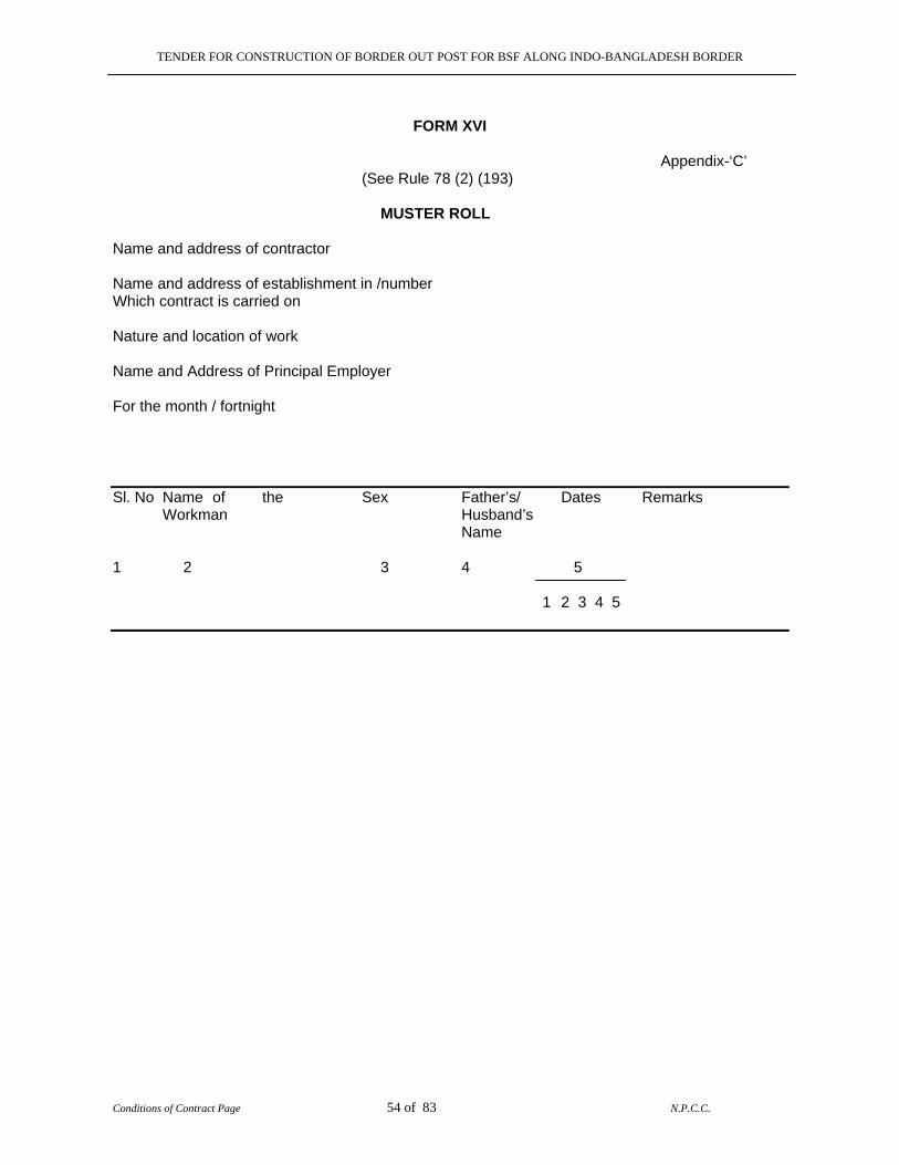
TENDER FOR CONSTRUCTION OF BORDER OUT POST FOR BSF ALONG INDO-BANGLADESH BORDER
Conditions of Contract Page 54 of 83 N.P.C.C.
FORM XVI
Appendix-‘C’ (See Rule 78 (2) (193) MUSTER ROLL Name and address of contractor Name and address of establishment in /number Which contract is carried on Nature and location of work Name and Address of Principal Employer For the month / fortnight Sl. No Name of the Sex Father’s/ Dates Remarks Workman Husband’s Name 1 2 3 4 5
1 2 3 4 5
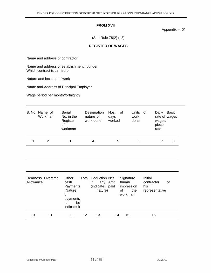
TENDER FOR CONSTRUCTION OF BORDER OUT POST FOR BSF ALONG INDO-BANGLADESH BORDER
Conditions of Contract Page 55 of 83 N.P.C.C.
FROM XVII Appendix – ‘D’
(See Rule 78(2) (o3) REGISTER OF WAGES Name and address of contractor Name and address of establishment in/under Which contract is carried on Nature and location of work Name and Address of Principal Employer Wage period per month/fortnightly S. No. Name of Serial Designation Nos. of Units of Daily Basic Workman No. in the nature of days work rate of wages Register work done worked done wages/ of piece workman rate 1 2 3 4 5 6 7 8
Dearness Overtime Other Total Deduction Net Signature Initial Allowance cash if any Amt thumb contractor or Payments (indicate paid impression his (Nature nature) of the representative of workman payments to be indicated) 9 10 11 12 13 14 15 16

TENDER FOR CONSTRUCTION OF BORDER OUT POST FOR BSF ALONG INDO-BANGLADESH BORDER
Conditions of Contract Page 56 of 83 N.P.C.C.
Appendix –‘E’
WAGE CARD Wage Card No. Name and address of Contractor Date of Issue Nature of work with location Designation Name of workman Month/Fortnight Rate of Wages 1 2 3 4 5 6 7 8 9 10 11 12 13 14 15 16 17 18 19 20 21 22 23 24 25 26 27 28 29 30 31 Morning Rate Evening Amount Initial Received from the sum of Rs. on account of my wagon Signature The wage card is valid for one month from the date of issue.

TENDER FOR CONSTRUCTION OF BORDER OUT POST FOR BSF ALONG INDO-BANGLADESH BORDER
Conditions of Contract Page 57 of 83 N.P.C.C.
FORM XIV
Appendix-‘F’ (See Rule 76)
EMPLOYMENT CARD
Name and address of contractor Name and address of establishment under which The contract is carried out Nature and location of work Name and address of Principal employer 1. Name of the workman 2. S. Name in the register of workman employed 3. Nature of Employment/Designation 4. Wage rate (with particulars of unit in
case of piece work)
5. Wage Period 6. Tenure of employment 7. Remarks
Signature of Contractor
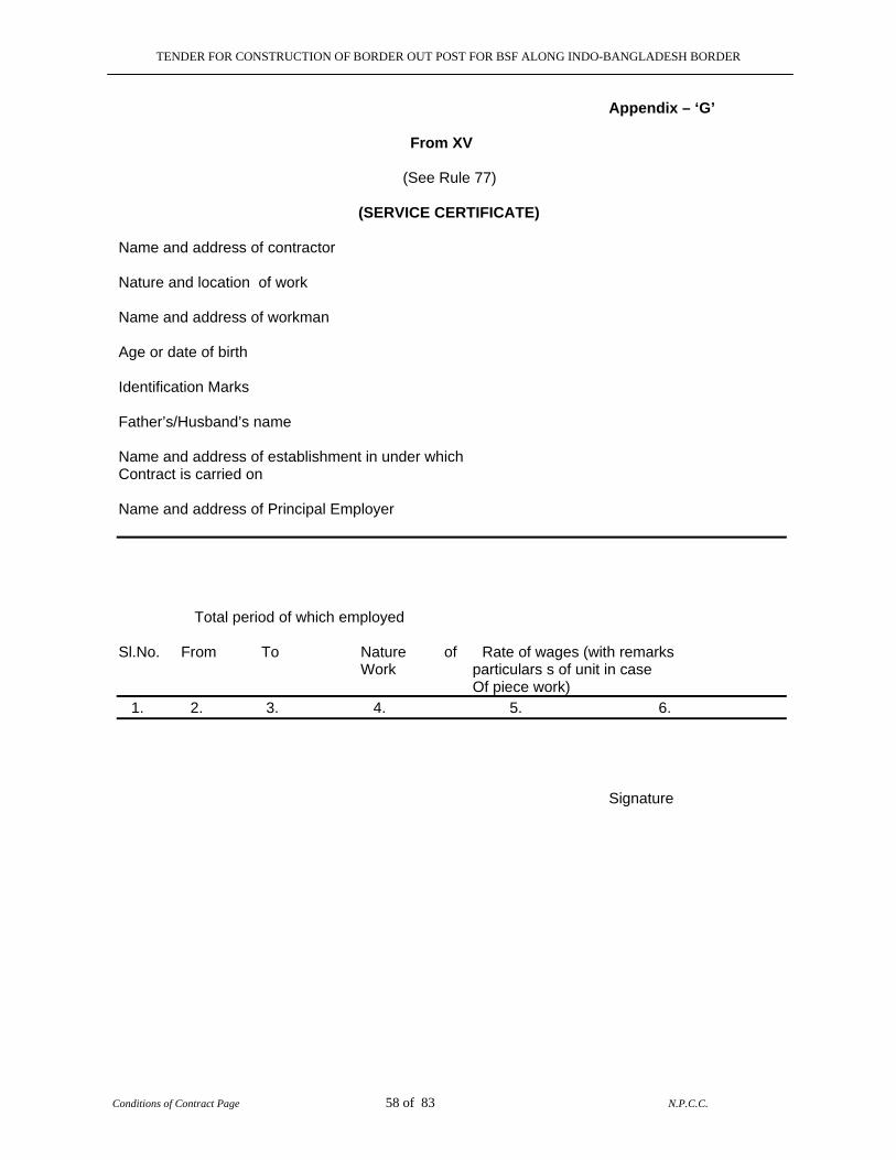
TENDER FOR CONSTRUCTION OF BORDER OUT POST FOR BSF ALONG INDO-BANGLADESH BORDER
Conditions of Contract Page 58 of 83 N.P.C.C.
Appendix – ‘G’ From XV (See Rule 77) (SERVICE CERTIFICATE) Name and address of contractor Nature and location of work Name and address of workman Age or date of birth Identification Marks Father’s/Husband’s name Name and address of establishment in under which Contract is carried on Name and address of Principal Employer Total period of which employed Sl.No. From To Nature of Rate of wages (with remarks Work particulars s of unit in case Of piece work) 1. 2. 3. 4. 5. 6. Signature

TENDER FOR CONSTRUCTION OF BORDER OUT POST FOR BSF ALONG INDO-BANGLADESH BORDER
Conditions of Contract Page 59 of 83 N.P.C.C.
Appendix – ‘H’ FROM XV (See Rule 77)
REGISTER OF FINES Name and address of contractor Name and address of establishment in/under which Contract is carried on- Nature and location of work Name and address of workman Name and address of Principal Employer Sl.No. Name of Father’s/Husband’s Designation/nature Act/Omission Date
of Workman Name of employment for which fine offence imposed 1. 2. 3. 4. 5. 6. Whether Name of person Wage period Amount of Date on Remarks Workman in whose and wages fine Imposed which fine Showed presence payable realized Cause employees Against explanation was fine heard

TENDER FOR CONSTRUCTION OF BORDER OUT POST FOR BSF ALONG INDO-BANGLADESH BORDER
Conditions of Contract Page 60 of 83 N.P.C.C.
Appendix-‘I’
LIST OF ACTS AND OMISSIONS FOR WHICH FINES CAN BE IMPOSED
In accordance with rule of Labour Regulation, to be displayed prominently at the site of work both in English and local language. 1. Willful insubordination or disobedience, whether alone or in combination with other.
2. Theft, fraud or dishonestly in connection with contractors beside a business of property of
NPCC
3. Taking or giving bribes or any illegal gratifications 4. Habitual late attendance.
5. Drunk-ness fighting riotous or disorderly or indifferent behavior
6. Habitual negligence
7. Smoking near or around the area where combustible or other materials are locked
8. Habitual indiscipline
9. Causing damage to work in the progress or to property of the NPCC or of the contractor
10. Sleeping on duty.
11. Malingering or slowing down work
12. Giving the false information regarding name, age, fathers name etc.
13. Habitual loss or wage cards supplied by the employer.
14. Unauthorized use of employers properly or manufacturing or making of unauthorized
articles at the work place 15. Bad workmanship in construction and maintenance by skilled workers, which is not
approved by the NPCC for which the contractors are compelled to undertake rectifications. 16. Making false complaints and/or misleading statements.
17. Engaging on trade within the premises of the establishment.
18. Any unauthorized divulgence of business affairs of the employees.
19. Collection or canvassing for the collection of any money within the premises of an
establishment unless authorized by the employer. 20. Holding meeting inside the premises with out previous sanction of the employers.
21. Threatening or intimidating any workman or employee during the working hours within the
premises.
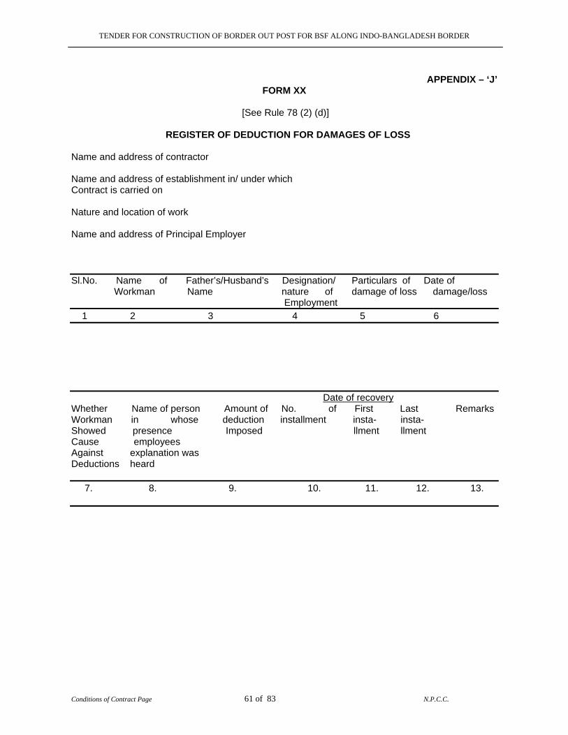
TENDER FOR CONSTRUCTION OF BORDER OUT POST FOR BSF ALONG INDO-BANGLADESH BORDER
Conditions of Contract Page 61 of 83 N.P.C.C.
APPENDIX – ‘J’
FORM XX [See Rule 78 (2) (d)] REGISTER OF DEDUCTION FOR DAMAGES OF LOSS Name and address of contractor Name and address of establishment in/ under which Contract is carried on Nature and location of work Name and address of Principal Employer Sl.No. Name of Father’s/Husband’s Designation/ Particulars of Date of Workman Name nature of damage of loss damage/loss Employment 1 2 3 4 5 6 Date of recovery Whether Name of person Amount of No. of First Last Remarks Workman in whose deduction installment insta- insta- Showed presence Imposed llment llment Cause employees Against explanation was Deductions heard 7. 8. 9. 10. 11. 12. 13.
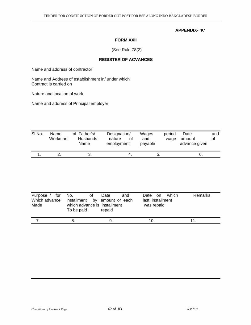
TENDER FOR CONSTRUCTION OF BORDER OUT POST FOR BSF ALONG INDO-BANGLADESH BORDER
Conditions of Contract Page 62 of 83 N.P.C.C.
APPENDIX- ‘K’ FORM XXII (See Rule 78(2) REGISTER OF ACVANCES Name and address of contractor Name and Address of establishment in/ under which Contract is carried on Nature and location of work Name and address of Principal employer Sl.No. Name of Father’s/ Designation/ Wages period Date and Workman Husbands nature of and wage amount of Name employment payable advance given 1. 2. 3. 4. 5. 6. Purpose / for No. of Date and Date on which Remarks Which advance installment by amount or each last installment Made which advance is installment was repaid To be paid repaid 7. 8. 9. 10. 11.
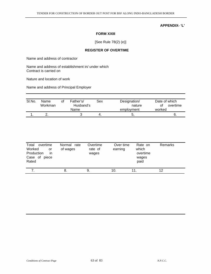
TENDER FOR CONSTRUCTION OF BORDER OUT POST FOR BSF ALONG INDO-BANGLADESH BORDER
Conditions of Contract Page 63 of 83 N.P.C.C.
APPENDIX- ‘L’
FORM XXIII [See Rule 78(2) (e)] REGISTER OF OVERTIME Name and address of contractor Name and address of establishment in/ under which Contract is carried on Nature and location of work Name and address of Principal Employer Sl.No. Name of Father’s/ Sex Designation/ Date of which Workman Husband’s nature of overtime Name employment worked 1. 2. 3 4. 5, 6. Total overtime Normal rate Overtime Over time Rate on Remarks Worked or of wages rate of earning which Production in wages overtime Case of piece wages Rated paid 7. 8. 9. 10. 11. 12
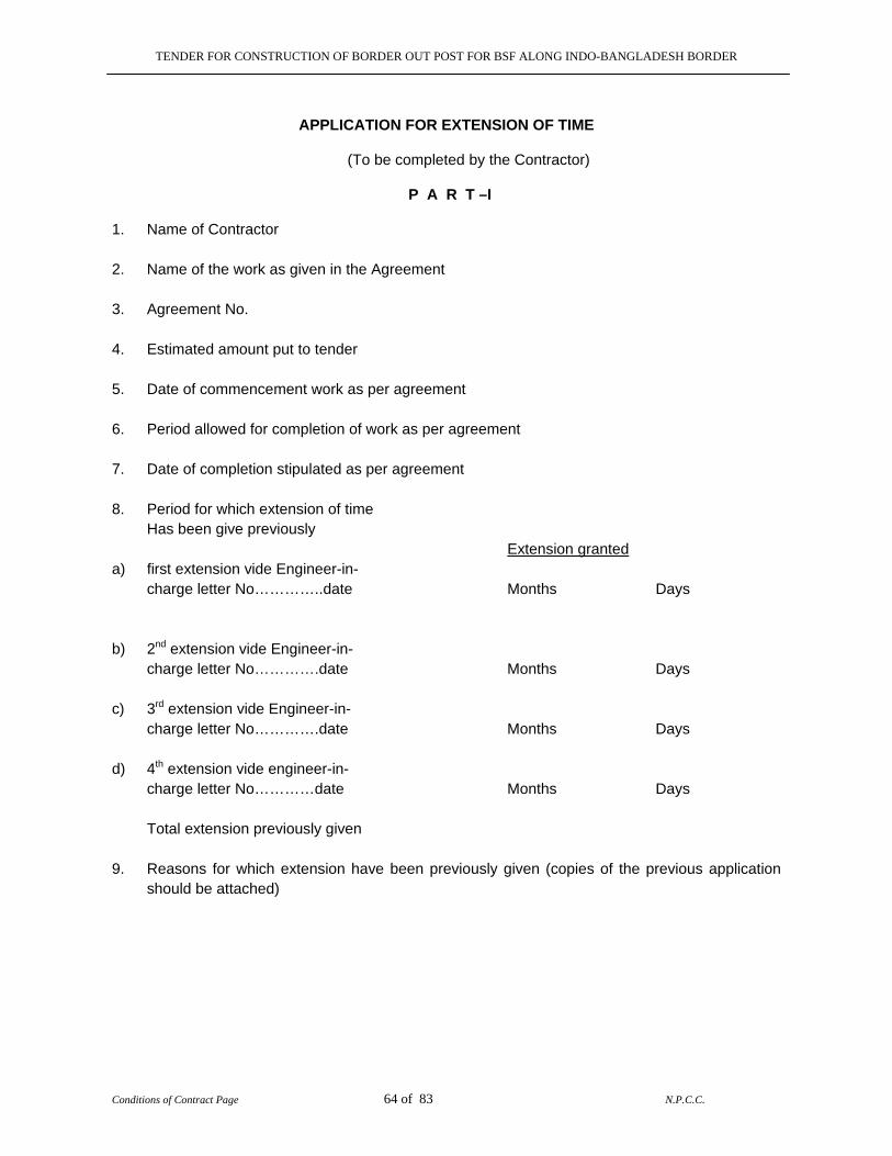
TENDER FOR CONSTRUCTION OF BORDER OUT POST FOR BSF ALONG INDO-BANGLADESH BORDER
Conditions of Contract Page 64 of 83 N.P.C.C.
APPLICATION FOR EXTENSION OF TIME
(To be completed by the Contractor) P A R T –I 1. Name of Contractor 2. Name of the work as given in the Agreement 3. Agreement No. 4. Estimated amount put to tender 5. Date of commencement work as per agreement 6. Period allowed for completion of work as per agreement 7. Date of completion stipulated as per agreement 8. Period for which extension of time
Has been give previously Extension granted a) first extension vide Engineer-in-
charge letter No…………..date Months Days
b) 2nd extension vide Engineer-in- charge letter No………….date Months Days
c) 3rd extension vide Engineer-in- charge letter No………….date Months Days
d) 4th extension vide engineer-in- charge letter No…………date Months Days Total extension previously given
9. Reasons for which extension have been previously given (copies of the previous application should be attached)
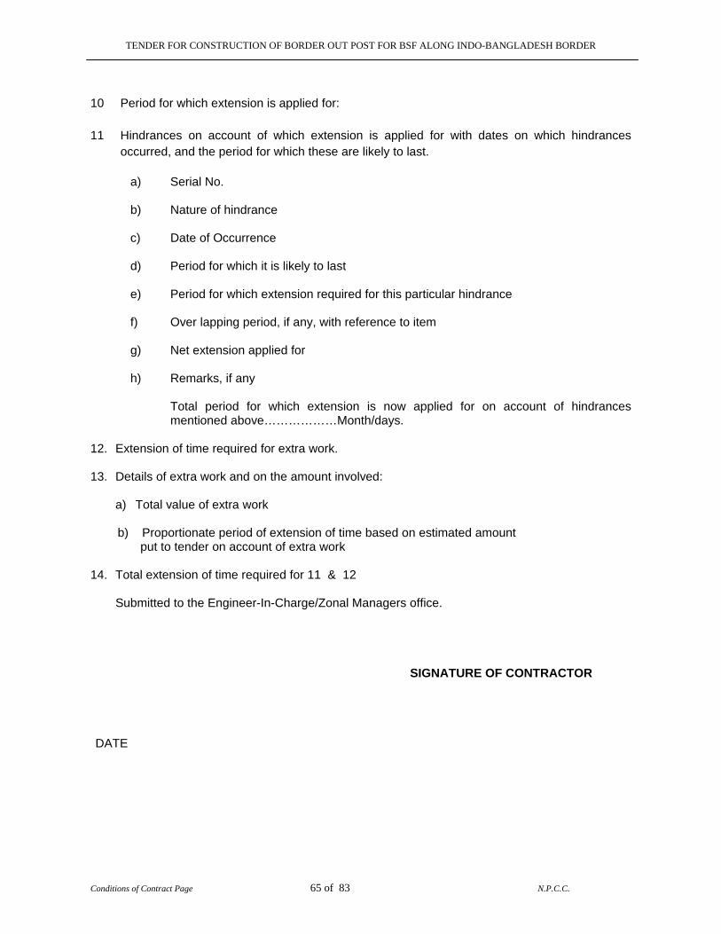
TENDER FOR CONSTRUCTION OF BORDER OUT POST FOR BSF ALONG INDO-BANGLADESH BORDER
Conditions of Contract Page 65 of 83 N.P.C.C.
10 Period for which extension is applied for: 11 Hindrances on account of which extension is applied for with dates on which hindrances
occurred, and the period for which these are likely to last.
a) Serial No.
b) Nature of hindrance
c) Date of Occurrence
d) Period for which it is likely to last
e) Period for which extension required for this particular hindrance
f) Over lapping period, if any, with reference to item
g) Net extension applied for
h) Remarks, if any
Total period for which extension is now applied for on account of hindrances mentioned above………………Month/days.
12. Extension of time required for extra work. 13. Details of extra work and on the amount involved:
a) Total value of extra work b) Proportionate period of extension of time based on estimated amount put to tender on account of extra work 14. Total extension of time required for 11 & 12
Submitted to the Engineer-In-Charge/Zonal Managers office.
SIGNATURE OF CONTRACTOR
DATE

TENDER FOR CONSTRUCTION OF BORDER OUT POST FOR BSF ALONG INDO-BANGLADESH BORDER
Conditions of Contract Page 66 of 83 N.P.C.C.
APPLICATION FOR EXTENSION OF TIME (PART – II )
1 Date of receipt of application from Contractor For the work in the Engineer-In-Charge/Zonal Manager office
2 Acknowledgement issued by Engineer-In-Charge/Zonal Manager vide His letter NO the
3 Engineer-In-Charge/Zonal Manager remarks regarding hindrances mentioned by The Contractor i) Serial No ii) Nature of hindrance
iii) Date of occurrence of hindrance
iv) Period for which hindrance, is likely to last
v) Extension of time period applied for by the contractor
vi) Over lapping period, if any giving reference to items
Which over lap
vii) Net period for which extension is recommended.
viii) Remarks as to why the hindrance occurred and Justification for extension recommended.
4 Engineer-In-Charge/Zonal Manager recommendations
(The present progress of the work should be stated and whether the work is likely to be completed by the date up to which extension has been applied for. If extension of time is not recommended, what compensation is proposed to be levied under the agreement.
SIGNATURE OF ENGINEER-IN-CHARGE APPROVAL OF ZONAL HEAD
TENDER FOR CONSTRUCTION OF BORDER OUT POST FOR BSF ALONG INDO-BANGLADESH BORDER
Conditions of Contract Page 67 of 83 N.P.C.C.
PROFORMA FOR EXTENSION OF TIME P A R T – III To NAME ADDRESS OF THE CONTRACTOR SUBJECT Dear Sir (s) Reference your letter No_____________ date _____________ in connection with the grant of extension of time for completion of the work….. The date of completion for the above mentioned work, is ………….as stipulated in the agreement, Dated…………… Extension of time for completion of the above mentioned work is granted up to___________ Without prejudice to the right of the NPCC to recover compensation for delay in accordance with the provision made in Clause of the said agreement dated the _______20......It is also clearly understood that the NPCC shall not consider any revision in contract price or any other compensation whatsoever due to grant of this extension. Provided that notwithstanding the extension hereby granted, time is and shall still continue to Be the essence of the said agreement. Yours faithfully, FOR NPCC LTD
TENDER FOR CONSTRUCTION OF BORDER OUT POST FOR BSF ALONG INDO-BANGLADESH BORDER
Conditions of Contract Page 68 of 83 N.P.C.C.
NATIONAL PROJECTS CONSTRUCTION CORPORATION LIMITED ( A GOVERNMENT OF INDIA ENTERPRISE )
PROFORMA OF BANK GUARANTEE IN LIEU OF EARNEST MONEY
(On Non-Judicial Stamp Paper) NPCC Ltd., NER(IBBW), H.No.-2, Apanjanpally, Sonai Road, SILCHAR-788006 (Assam) In consideration of NPCC Ltd. having its Registered Office at 30-31 Raja House, Nehru Place, New Delhi-110019 , (herewith called “NPCC”) which expression shall unless repugnant to the subject or context. Include its successors and assigns having issued Notice Inviting Tender No…………and M/S…………………. having its Registered Head Office at………………… (hereinafter called the “TENDERER”) is to participate in the said tender for…………… Whereas NPCC as a special case, has agree to accept an irrevocable and unconditional Bank Guarantee for an amount of…….. to be made by the tenderer, as a condition precedent for participation in the said tender. We the…………(hereinafter called the “BANK”)having its Registered, Office at…………. And branch office at……… do hereby unconditionally and irrevocably undertake to pay an amount of Rs. …. to NPCC shall be conclusive and binding on us irrespective of any dispute or differences that may be raised by the tender by the tenderer. Any change in the constitution of the tenderer or the Bank shall not discharge out liability under the guarantee We, the……….Bank, lastly undertake not to revoke this guarantee during its currency without the prior consent of NPCC in writing and this guarantee shall remain valid up to……….. Unless a claim is made within three months from the date of expiry i.e. ………., we shall be relieved of our liability under this guarantee thereafter. PLACE, FOR AND ON BEHALF OF BANK DATED: WITNESS. 1. 2.
TENDER FOR CONSTRUCTION OF BORDER OUT POST FOR BSF ALONG INDO-BANGLADESH BORDER
Conditions of Contract Page 69 of 83 N.P.C.C.
PROFORMA OF BANK GUARANTEE FOR
( ISD / PERFORMANCE ) (On Non-Judicial Stamp Paper)
NPCC Ltd., NER(IBBW), H.No.-2, Apanjanpally, Sonai Road, SILCHAR-788006 (Assam) “NPCC” which expression shall include its successors and assigns /supply order No dated (hereinafter called the contract) to M/s. ………………………………. (hereinafter called the contractor / supplier ) at a total price of Rs……………………. Subject to the terms and conditions contained in the contract. WHEREAS the terms and conditions of the contract require the contractor to furnish a bank guarantee for Rs………………(Rupees……………….) being …………% of the total value of the contract for proper execution and due fulfillment of the terms and conditions contained in the contract. We, the …………………Bank, (hereinafter called the “Bank”) do hereby unconditionally and irrevocably undertake to pay to NPCC immediately on demand in writing and without protest/or demur all moneys payable by the contractor/supplier to NPCC in connection with the execution/supply of and performance of the works/equipment. Inclusive of any loss, damages, charges, expenses and costs caused to or suffered by or which would be caused to or suffered by NPCC by reason of any breach by the contractor/supplier of any of the terms and conditions contained in the contract as specified in the notice of demand made by NPCC to the bank. Any such demand made by NPCC on the bank shall be conclusive evidence of the amount due and payable by the bank under this guarantee. However, the Bank’s liability under this guarantee, shall be limited to Rs…………….in the aggregate and the bank hereby agrees to the following terms and conditions:- (i) This guarantee shall be a continuing guarantee and irrevocable for all claims of NPCC as
specified above and shall be valid during the period specified for the performance of the contract including the period of maintenance/warranty i.e. up to……………
(ii) We, the said bank further agree with NPCC that NPCC shall have the fullest liberty without
our consent and without affecting in any manner our obligations and liabilities hereunder to vary any of the terms and conditions of the said contract or to extend time for performance of contract by the contractor from time to time or to postpone for any time or from time to time any of the powers exercisable by NPCC or any indulgence by NPCC to the contractor or by any such matter or thing whatsoever, which under the low relating to the sureties would, but for this provision, have effect of so relieving us.
(iii) This guarantee/undertake shall be in addition to any other guarantee or security whatsoever
NPCC may now or at any time have in relation to the performance of the works/equipment and the company shall have full re-course to or enforce this security in performance to any other security or guarantee which the NPCC may have or obtained and there shall be no forbearance on the part of the company in enforcing or requi8ring enforcement of any other security which shall have the effect of releasing Bank from its full liability. It shall not be necessary for NPCC to proceed against the said contractor/supplier before proceeding against the Bank.
TENDER FOR CONSTRUCTION OF BORDER OUT POST FOR BSF ALONG INDO-BANGLADESH BORDER
Conditions of Contract Page 70 of 83 N.P.C.C.
(iv) This guarantee/undertaking shall not be determined or affected by the liquidation or winding up, dissolution or change of constitution or insolvency of the supplier/contractor, but shall in all respects and for all purposes be binding and operative until payment of all moneys payable to NPCC in terms thereof are paid by the Bank.
(v) The Bank hereby waives all rights at any time inconsistent with the terms of this Guarantee
and the obligations of the Bank in terms hereof , shall not be otherwise effected of suspended by reasons of any dispute or disputes having been raised by the supplier contractor (whether5 or not pending before any Arbitrator, Tribunal or Court) or any denial of liability by the Bank to NPCC in terms hereof.
We, the said Bank lastly undertake not to revoke this guarantee during its currency except with the previous consent of NPCC in writing. Unless a claim is made in writing within three months from the date of expiry of this guarantee i.e.…………..we shall be relieved from all liabilities under this guarantee thereafter. Signed this………………………day of……………………at…………… For and on behalf of bank WITTNESS 1._____________________ 2._____________________
TENDER FOR CONSTRUCTION OF BORDER OUT POST FOR BSF ALONG INDO-BANGLADESH BORDER
Conditions of Contract Page 71 of 83 N.P.C.C.
NATIONAL PROJECTS CONSTRUCTION CORPORATION LIMITED (A Govt of India Enterprise)
PROFORMA OF BANK GUARANTEE
(On Non-Judicial Stamp Paper) (IN LEU OF SECURITY DEPOSIT)
NPCC Ltd., NER(IBBW), H.No.-2, Apanjanpally, Sonai Road, SILCHAR-788006 (Assam) In consideration of the National Projects Construction Corporation Ltd. (hareinafter called “the NPCC”) which expression shall include its successors and assigns having awarded to M/s…………………………………… (hereinafter called “The Supplier/Contractor”) which expression shall wherever the subject or context so permits includes its successors and assigns) a contract in terms inter-alia of the company’s letter no…………………………..dated …………………. and the contract/purchase condition of the company and upon the condition of the Supplier/Contractor furnishing Security for the performance the supplier obligations and or discharge of the contractors suppliers liability under and and/or in connection with the said supply contract upto a sum of Rs. ………………….(Rupees …………………………. Only) We, ……………………… (hereinafter called “The Bank”) which expression shall include its successors and assigns) hereby undertake and guarantee payment to NPCC forwith on the same day on demand in writing and without protest or demur of any and all moneys payable by the supplier /contractor to the Company under in respect or in the connection with the said contract inclusive of all the losse, damages, costs, charges and expenses and other moneys payable in respect of the above as specified in any notice of demand made by the company to the Bank with reference to this guarantee upto and aggragate limit of Rs. ……………… (Rupees …………….. only) and the Bank hereby agree with the company that. 1. This Guanrantee shall be continuing guarantee and shall …………….. remain valid and
irrevocable for all claims of the company and liabilities of Supplier/Contractor arising upto and until midnight of ………………
2. This Guarantee shall be in addition to any other Guarantee or security whatsoever that the
Company now or at any time have in relation to the supplier’s obligations/liabilities under and/or in connection with the said supply/contract, and the company shall have full authority to take recourse or to enforce this security in preference to any other Guarantee or Security which the company may have or obtain and no forbearence on the part of the Company in enforcing or requiring enforcement of any other Security shall have the effect of relaesing the bank from its liability hereunder.
3. The Company shall be at liberty without reference to the Bank and without affecting the full
liability of the Bank hereunder to take any other security in respect of the Supplier’s/Conractor’s obligations and/ or liabilities under or in connection with the said supply/contract or to grant time and /or indulgence to the supplier / contractor or to increase or otherwise vary the prices of the total contract value or to release or to forbear from enforcement of all or any of the conditions under the said supply / contract and / or the remedies of the Company under any other security/securities now or hereafter held by the Company and no such dealings, increases or other indulgence(s) or arrangement(s) with the supplier / contractor or releasing of forbearence whatsoever shall have the effect of releasing the Bank from its full liability to the company hereunder or prejudicing rights of the company against the Bank.
TENDER FOR CONSTRUCTION OF BORDER OUT POST FOR BSF ALONG INDO-BANGLADESH BORDER
Conditions of Contract Page 72 of 83 N.P.C.C.
4 This Guarantee shall not be determined or affected by the liquidation or winding up, dissolution or change or constitution or insolvency of the supplier/ contractor but shall in all respects and for all purposes be binding and operative until payment of all moneys payable to the company in terms thereof
5. The bank hereby waives all rights at time in consistent with the terms of this Guarantee and
the obligations of the Bank in terms hereof shall not be otherwise affected or suspended by reason of any dispute or disputes having been raised by the supplier / contractor (whether or not pending before any Arbitrator , Tribunal or court ) or any denial or liability by the supplier / contractor stopping / preventing or purporting to stop or prevent any payment by the Bank to the company in terms thereof.
6. The amount stated in any notice of demand addressed by the company to the Guarantor as
the liable to be paid to the company by the supplier/ contractor or as suffered or incurred by the company on account of any losses or damages, costs, changes and/ or expenses shall as between the Bank and the company be conclusive of the amount so liable to be paid to the company or suffered or incurred by the company as the case may be and payable by the Guarantor to the company in terms hereof subject to a maximum of Rs …….(Rupees………………).
7. Unless demand or claim under this Guarantee is made on the Guarantor in writing within
three months from the date of expiry of the Guarantee i.e. up to ……… the Guarantor shall be discharged from all liabilities under this Guarantee there under.
Notwithstanding anything contained herein before our liability under this Guarantee is restricted to Rs…….. (Rupees……………only).This Guarantee will expire on ………….Any claim under this Guarantee must be received by us within three month from the date of expiry …….i.e.……(date) and if no such claim has been received by us that date all your rights under this Guarantee will cease. Place for and on behalf of the Bank Date WITNESS 1 2
TENDER FOR CONSTRUCTION OF BORDER OUT POST FOR BSF ALONG INDO-BANGLADESH BORDER
Conditions of Contract Page 73 of 83 N.P.C.C.
FORM OF BANK GUARANTEE TO SECURE A LUMP-SUM ADVANCE
(On Non-Judicial Stamp Paper) To NPCC Ltd., NER(IBBW), H.No.-2, Apanjanpally, Sonai Road, SILCHAR-788006 (Assam) In consideration of National Projects Construction Corporation Limited having its head office at 30-31, Raja House, Nehru Place, New Delhi (hereinafter called NPCC which expression shall unless repugnant to the subject or context include its administrators, successors and assigns) having agreed under the terms and conditions of the Contract agreement No.__________ dated ___________ made between ____________*___________ and NPCC in connection with the work of ____________________ (hereinafter called “the said Contract”) to make at the request of the Contractor a lump-sum advance of Rs._____________________(Rupees__________________________________only) for utilizing it for the purpose of the Contract on his furnishing a guarantee acceptable to NPCC we, the __________________________ Bank (hereinafter referred to as “the said Bank” ) and having our registered office at_____________________________________ do here by guarantee the due recovery by NPCC of the said advance with interest thereon as provided according to the terms and conditions of the Contract. If the said Contractor fails to utilize the said advance for the purpose of the Contract and/ or the said advance together with interest thereon as aforesaid is not fully recovered by NPCC we, the __________________________ Bank hereby unconditionally and irrevocably undertake to pay to NPCC on demand and without demur to the extent of the said sum of Rs. _______________________________ (Rs. ___________________________only) any claim made by NPCC on us for the loss or damage caused to or suffered by NPCC by reason of not being able to recover in full the said sum of Rs. _____________________ ( Rs. ______________________________only) with interest as aforesaid.
2. We, the _________________________ Bank further agreed that NPCC shall be the sole judge of and as to whether the said contractor has not utilized the said advance or any part there of for the purpose of the Contract and the extent of loss or damage caused to or suffered by NPCC on account of the said advance together with interest not being recovered in full and the decision of NPCC that the said Contractor has not utilized the said advance or any part thereof for the purpose of the Contract and as to the amount or amounts loss or damage caused to or suffered by NPCC shall be final and binding on us.
3. We, the said Bank further agree that the Guarantee therein contained shall remain in full
force and effect during the period that would be taken for the performance of the said Contract and till the said advance with interest has been fully recovered and its claims satisfied or discharged and till the Accepting Authority of the Contract certifies that the said advance with interest has been fully recovered from the said Contractor, and accordingly discharges this Guarantee subject, however, that the NPCC shall have no claim under this Guarantee after 90 (ninety) days from the date of completion of the said Contract i.e. ___________ (date) or from date of cancellation of the said Contract, as the case may be, unless a notice of the claim under this Guarantee has been served on the Bank before the expiry of the said period in which case the same shall be enforceable against the Bank notwithstanding the fact, that the same is enforced after the expiry of the said period.
TENDER FOR CONSTRUCTION OF BORDER OUT POST FOR BSF ALONG INDO-BANGLADESH BORDER
Conditions of Contract Page 74 of 83 N.P.C.C.
4. NPCC shall have the fullest liberty without effecting in any way the liability of the Bank
under this Guarantee or indemnify, from time to time to vary any of the terms and conditions of the said Contract or the advance or to extend time of performance by the said Contractor or to postpone for any time and from time to time any of the powers exercisable by it against the said Contractor and either to enforce a forbear from enforcing any of the terms and conditions governing the said Contract or the advance or securities available to NPCC and the said Bank shall not be released from its liability under this presents be any exercise by NPCC of the liberty with reference to the matters aforesaid or by reason of time being given to the said Contractor or any other forbearance, act or omission on the part of NPCC or any indulgence by NPCC to the said Contractor or of any other matter or thing whatsoever which under the law relating to sureties would but for this provision have the effect of so releasing the Bank from its such liability.
5. It shall not be necessary for NPCC to proceed against the Contractor before proceeding
against the Bank and the Guarantee herein contained shall be enforceable against the Bank notwithstanding any security which NPCC may have obtained or obtain from the Contractor shall at the time when proceedings are taken against the Bank hereunder be outstanding or unrealized.
6. We, the said Bank lastly undertake not to revoke this Guarantee during its currency
except with the previous consent of NPCC in writing and agree that any change in the Constitution of the said Contractor or the said Bank shall not discharge our liability hereunder. In presence of: Dated this_______ day of _____200_ WITNESS 1. For and on behalf of (The Bank)
Signature ___________________
2. Name & Designation ____________
Authorization No. ______________
Name & Place _________________
Bank’s seal ____________________
The above Guarantee is accepted by NPCC. For and on behalf of NPCC Signature _______________________ Name & Designation ______________ _______________________________ Dated __________________________
TENDER FOR CONSTRUCTION OF BORDER OUT POST FOR BSF ALONG INDO-BANGLADESH BORDER
Conditions of Contract Page 75 of 83 N.P.C.C.
Note * For Proprietary Concerns Shri ___________________ son of __________________ resident of _______________ Carrying on business under the name and style of __________________ at ___________ (hereinafter called “the said Contractor” which expression shall unless the context requires otherwise include his heirs, executors, administrators and legal representatives). For partnership Concerns 1. Shri ___________ son of ______________resident of _____________ 2. Shri ___________son of ______________ resident of _______________ carrying on business in co-partnership under the name and style of ____________ at _____________ (hereinafter collectively called “the said Contractor” which expression shall unless the context requires otherwise include each of them and their respective heirs, executors, administrators and legal representatives). For Companies M/s ____________________ a company registered under the Companies Act, 1956 and having its registered office at _____________________in the state of _______________ (Hereinafter called “the said Contractor” which expression shall unless the context requires otherwise include its administrators, successors and assigns).
TENDER FOR CONSTRUCTION OF BORDER OUT POST FOR BSF ALONG INDO-BANGLADESH BORDER
Conditions of Contract Page 76 of 83 N.P.C.C.
GUARANTEE TO BE EXECUTED BY CONTRACTOR FOR REMOVAL OF DIFFECTS AFTER COMPLETION IN RESPECT OF WATER PROOFING WORKS The agreement made this ………………... day of …………….. Two thousand One and ………. Between …………………………. (Hereinafter called Guarantor of the one part) and the NPCC (hereinafter called the Execution Agency of the other part). WHEREAS this agreement is supplementary to a contract (hereinafter called the contract), dated ………… and made between the GUARANTOR OF THE ONE part and the NPCC of the other part, whereby the contractor, inter-alia, undertook to render the buildings and structures in the said contract recited completely water and leak proof. AND WHEREAS the Guarantor agreed to give a guarantee to the effect that the said structures will remain water and leak proof for ten years from the date of handing over o the structure of water proofing treatment. NOW THE GUARANTOR hereby guarantees that water proofing treatment given by him will render the structures completely leak proof and the minimum life of such water proofing treatment shall be ten years to be reckoned from the date after the maintenance period prescribed in the contract. Provided that the Guarantor will not be responsible for leakage caused by earthquake or structural defects of misuse of roof or alteration and for such purpose. a) Misuse of roof shall mean any operation, which will damage proofing treatment, like
chopping of fire wood and things of the same nature which might cause damage to the roof. b) Alternation shall mean construction of an additional storey or a part of the roof or
construction adjoining to existing roof whereby proofing treatment is removed in parts. c) The decision of the engineer -in-Charge with regard to cause of leakage shall be final. During this period of guarantee, the Guarantor shall make good all defects and incase of any defect being found render the building water proof to the satisfaction of an Engineer-In-Charge/Zonal Manager at his cost and shall commence the work for such rectification within seven days from the date of issue of notice from the Engineer-In-Charge/Zonal Manager calling upon him to rectify the defects failing which the work shall be got done by the NPCC by some other Contractor at the guarantor's cost and risk. The decision of Engineer-In-Charge/Zonal Manager as to the cost, payable by the Guarantor shall be final and binding. That if the Guarantor fails to execute the water proofing or commits breach there -under, Then the guarantors will indemnify the principle and his successors against all laws damage, cost, expense or otherwise which may be incurred by him by reason of any default on the part of the GUARANTOR in performance and observance of this supplementary agreement as to the amount

TENDER FOR CONSTRUCTION OF BORDER OUT POST FOR BSF ALONG INDO-BANGLADESH BORDER
Conditions of Contract Page 77 of 83 N.P.C.C.
of loss and /or damage and /or cost incurred by the NPCC, the decision of the engineer-in -Charge will final and binding of the parties. IN WITNESS WHEREOF these presents have been executed by the Obligator……and by ….And for and on behalf of the NPCC on the day, month and year first above write. Signed, sealed and delivered by Obligator in the presence of- 1. 2. Signed for and on behalf of the NPCC by………………………. In presence of 1. 2.
TENDER FOR CONSTRUCTION OF BORDER OUT POST FOR BSF ALONG INDO-BANGLADESH BORDER
Conditions of Contract Page 78 of 83 N.P.C.C.
SPECIAL CONDITIONS OF CONTRACT (SCC) FOR
“CONSTRUCTION OF BORDER OUT POSTS FOR BORDER SECURITY FORCE ALONG INDO-BANGLADESH BORDER IN THE STATE OF WEST BENGAL & TRIPURA”
GENERAL: The following special conditions shall be read in conjunction with General with general Conditions of contract. If there are any provisions in these Special Conditions, Which are at variance with the provisions of General Conditions of Contract, the provisions in these special Conditions shall take precedence. (1) The work in general shall be carried out as per CPWD specification 1996 Vol. I To Vl (Civil
works)/ 1994 New Delhi for electrical works updated with correction slips issued up to last date of submission of tender.
(2) For items not covered under CPWD Specification, 1996 Vol. 1 To Vl (Civil works)/ CPWD
Specification 1994 (Electrical works) as above, the work shall be done as per latest relevant ISI Codes of practice.
1.0 INTRODUCTION: 1.1 The work is of Construction of Border Out Post for BSF along Indo-Bangladesh Border in the
State of West Bengal & Tripura and being funded by Government of India, Ministry of Home Affairs.
2.0 APPROACHES TO SITE: The proposed site for BOPs falls along Indo-Bangladesh Border under the State of
West Bengal & Tripura. 3.0 SCOPE OF WORK: The Scope of work includes Construction of Composite BOPs using reinforcement steel,
steel doors, steel windows, CGI sheets, steel structure & retaining wall (if required), cement concrete, brick work, earth work, drainage, sanitary work, electrification etc. as per design, drawings, specifications and BOQ.
4.0 LETTER OF UNDERTAKING: The tender shall be accompanied by Letter of acceptance and letter of undertaking as per
proforma given in this tender document.
4.1 Any tender not accompanied by Letter of undertaking in accordance with aforesaid provision of Notice Inviting Tender and Instructions to Tenderer shall be rejected.
4.2 Once the Tenderer has given an unconditional acceptance to the tender conditions in its
entirety, he is not permitted to put any remark(s)/conditions(s) (except unconditional rebate on price, if any) in/along with the tender.
4.3 In case the conditions 4.1 & 4.2 mentioned above are found violated at any time after
opening of tender, the tender shall be summarily rejected and NPCC shall, without prejudice to any other right or remedy, be at liberty to forfeit the full consolidated Earnest Money submitted with the tender.
TENDER FOR CONSTRUCTION OF BORDER OUT POST FOR BSF ALONG INDO-BANGLADESH BORDER
Conditions of Contract Page 79 of 83 N.P.C.C.
5.0 SITE VISIT AND COLLECTING LOCAL INFORMATION:
Before tendering, the tenderer is advised to visit the site, its surrounding, access and satisfy themselves about the local conditions such as approach roads to the site, availability of water & power supply, application of taxes, duties and levies as applicable, nature of ground, soil and sub-soil condition, underground water table level, accommodations they may require etc., river regime, river water levels, other details of river, steams & any other relevant information required by them to execute complete scope of work. The tenderer may obtain all necessary information as to risks, contingencies & other circumstances (insurgencies etc.) which may influence or affect their tender. Tenderer shall be deemed to have considered site conditions whether he has inspected it or not and to have satisfied himself in all respect before quoting his rates and no claim or extra charges whatsoever in this regard shall be entertained / payable by the NPCC at a later date.
6.0 SALES TAX ON WORKS CONTRACT & TURNOVER TAX:
The liability of payment of sales tax on works contract, Turnover Tax, Service Tax, Building & Construction Labour cess or all other similar tax(es) including VAT shall be to the contractor's account. Tax deductions at source shall be made as per laws prevalent in the state.
It will be incumbent upon the contractor to obtain a registration certificate as a dealer under the Local Sales Tax Act and the Central Sales Tax Act and the Contractor shall furnish necessary evidence to this effect to NPCC. Sales Tax/VAT or any other tax(es) etc. on the transactions between the Contractor and his Sub-contractor/Vendors etc. shall not be reimbursed by NPCC.
7.0 TRANSFER OF BID DOCUMENTS:
Transfer of bid documents purchased by one intending bidder to another is not permissible.
8.0 HANDING OVER OF SITE:
The site of the work is located in border area part of which may be inaccessible at times and is insurgency prone. The bidder is advice to visit the site and to ascertain by himself the working security logistics and other constraints at site. The contractor shall be responsible of all over ground and under ground structures hindrances and constructions for the site of worker
The contractor should note that area for construction shall be made available in phases as per availability. The work is required to be carried out in constrained situations and nothing extra shall be payable to the contractor due to this phasing /complete the entire project within total stipulated time.
The efforts will be made by the NPCC to hand over the site to the contractor expeditiously on availability. However incase of any delay in handing over the site to the contractor due to any force majure, security, inaccessibility problem, should be clearly understood that NPCC shall not consider any revision in contract price or any other compensation whatsoever viz. Towards idleness of contractors labour, equipment etc. due to any reason whatsoever and decision of NPCC Engineer-In-Charge/Zonal Manager shall be final and binding on the contractor.
9.0 The NPCC reserves the right to award the work to a single party or to split the work amongst
two or more parties as deemed necessary without assigning any reason whatsoever.
TENDER FOR CONSTRUCTION OF BORDER OUT POST FOR BSF ALONG INDO-BANGLADESH BORDER
Conditions of Contract Page 80 of 83 N.P.C.C.
10.0 UTILIZATION OF WORK FORCE OF NPCC: As per requirement of Contractor, NPCC may supply work force (if available) in the following categories to assists the contractor in execution of the work at the fixed recovery rates mentioned against each category: Attendant/Mechanic/Operator/Helper etc: - Monthly rate of recovery per persons Rs.12,000/- (Rs. Twelve Thousand only) per month or any higher rate against each work force. Recoveries as stated above will be made by NPCC from the monthly running account bills. The contractor shall deploy such work force on the execution of the works as per their trades and deployment shall be for the entire contract period till completion and handing over the works. In case of any worker proceeding on Earned/Medical leave, NPCC will provide a substitute for deployment to the contractor, failing which no proportionate recovery shall be made.
Further the monthly rate per person is for the purpose of recovery only and in no way shall be construed to be the rate applicable for working out analysis, justification of rates, extra items, claims etc.
11.0 NO ESCALATION PAYMENT / PRICE VARIATION ADJUSTMENT:
The rates quoted by the contractor shall be firm and fixed for entire contract period as well as extended period for completion of works. All rates as per bill of quantities (BOQ) shall be firm & fixed for entire contract period as well as for extended period for completion of the project. No claim on account of any price variation / Escalation on whatsoever ground shall be entertained at any stage of works.
12.0 The rates and prices to be tendered in the bill of quantities are for completed and finished
items of works and complete in all respects. It will be deemed to include all constructional plant, labour, supervision, materials, transport, all temporary works, erection, maintenance, contractor’s profit and establishment / overheads, together with preparation of designs, drawings pertaining to casting yard (if required). Staging, form work, stacking yard, etc. all general risks, taxes, royalty, duties, cess, octroi and other levies, insurance liabilities and obligations, set out or implied in the tender documents and contract.
13.0 Price shall be entered against each item in bill of quantities where quantities or LS (lump-
sump) has been mention. The cost of item against which the contractor has filled to entire a rate or price shall be deemed to be covered by rates and price of other items in the bill of quantities and no payment shall be made for the quantities executed for items against which rate has not been quoted by contractor. No rate is to be quoted against ITEMS FOR WHICH NO Quantity is given. However the contractor has to quote rate against "LS"(LUMP-SUMP) ITEMS.
14.0 The materials products used on the works shall be one of the approved makes/brands out of
list of manufacture RS / brands /makes given in the tender documents. The contractor shall submit samples /specimens out of approved makes of materials /products to the Engineer-In -Charge for prior approval. In exceptional circumstances Engineer-In-Charge may allow alternate equivalent makes /brands of products /materials at his sole discretion .The final choice of brands / makes shall remain with the Engineer-In-Charge, whose decision in the matter shall be final and binding and nothing extra on this account shall be payable to the contractor.
TENDER FOR CONSTRUCTION OF BORDER OUT POST FOR BSF ALONG INDO-BANGLADESH BORDER
Conditions of Contract Page 81 of 83 N.P.C.C.
Incase signal brand / make are mentioned other equivalent makes brands may be considered by the engineer in charge with prior approval .Incase of variance in CPWD/is specification from approved products makes specification the specification of approved products make shall prevail for which nothing shall be paid extra to the contractor.
15.0 As soon as possible after the contract is concluded the contractor should submit a time and progress charts and gets it approved by the NPCC. The chart shall be prepared in direct relation to the time stated in the contract documents for completion of items of works. it shall indicate the forecast of the dates of commencement and completion of various trades of section of the work and may be amended as necessary by agreement in the contract documents. To ensure good progress during execution of the work the contractor shall in all cases in which the time allowed for any work exceeds one month (for jobs for which a separate program as above has been agreed upon ) has to complete 1/8 of the whole work before 1/4 of the whole time allowed in the contract has elapsed 3 /8 of the work before one half of such time has elapsed and 3/4 of the work before 3/4 of such time has elapsed .The physical before including photographs shall be submitted by the contractor on the prescribed format & The intervals as decided by the engineer in-charged .
16.0 FURNISHED OFFICE ACCOMMODATION & MOBILITY AND COMMUNICATION TO BE PROVIDED BY CONTRACTOR TO NPCC:
On acceptance of tender, the Contractor shall provide/construct a suitable furnished site
office/transit camp equipped with basic facilities such as telephone(s), fax, internet, photocopier, computer(s) and printer(s) along with operator(s), regular electric & drinking water supply, stationary & consumables etc. as per requirement of the work & to the satisfaction of Engineer-in-Charge and One no. inspection vehicle (not to be less than 2200CC) in good condition (including fuel & driver) etc. with atleast 3000km. running in a month exclusively for the inspection of the job by Engineer-in-Charge and other staff of NPCC and shall maintain the aforesaid facilities intact/operational since inception to completion of the work including defects liability period. Contractor will not be paid any extra cost towards the same. However, if the Contractor will not provide the aforesaid facilities to NPCC, recovery shall be made from the bills of the Contractor as per actual.
The contractor shall also make sufficient arrangements for photography/videography so that
photographs/videos can be taken of any specific activity at any point of time. The contractor shall also provide software like MS Project etc. for the purpose of preparing progress report etc.
17.0 The contractor shall make all arrangements for ground breaking ceremony/ inaugural function etc. for the project as required and the cost towards is deemed to be included in his rates/offer. Any expenditure already incurred/to be incurred by NPCC, shall be recovered from the contractor. 18.0 The contractor if required shall demolish old structures on the proposed site properly. The
useful material shall be the property of the owner /NPCC and these materials shall be stacked in workmanship like at the place specified by the Engineer-In-Charge/Zonal Manager.
19.0 In a mandatory of the contractor provided safely equipment and gadgets to its all workers
supervisor and technical staff engaged in the execution of the work while working specifications nos. of this equipment and gadgets shall also be provide to NPCC by the contractor at his won cost for use of NPCC officials and /or workforce.
While working /supervision at site, no staff/ worker shall be allowed to enter the site without these equipments/gadgets
TENDER FOR CONSTRUCTION OF BORDER OUT POST FOR BSF ALONG INDO-BANGLADESH BORDER
Conditions of Contract Page 82 of 83 N.P.C.C.
The cost of the above equipments /gadgets shall be included in the rates quoted by the contractor for the items & works as per bill of Quantities and contractor shall not be entitled for any extra coast in these regard. The above norm is to be strictly complied with a site .In case the contractor is found to be deficient in providing safety equipment/ gadgets in opinion of Engineer-In-Charge, the engineer in charge at his opinion can procure the same at the risk & cost of contractor and provide the same for the use of work site and shall make the recoveries from the bills of the contractor for the same. The decision of the engineer -in -charge shall be final and binding on contractor in this regard.
20.0 The site (S) of the proposed shall be handed over in parts as per approved program in conjunction with pace of actual progress. The work is to be executed in such a manner that the traffic flow on the road (where work is carried out) is not disrupted Traffic diversion is to be done and maintained as per specification by the contractor at his own cost and the contractor shall not be entitled for any extra payment whatsoever on this regard.
21.0 If required, the contractor has to do site clearance, enabling work, barricading, shifting /
realignment of existing utility services etc at his own cost and the contractor shall not be entitled for any extra payment whatsoever in this regard.
22.0 The contractor should note that this project falls in the forest area which is governed by
Forest conservation Act 1980. The contractor shall be responsible for obtaining all the approvals and to meet the requirements of Forest conservation Act 1980 or any other applicable Act.
23.0 i) That the project has been specifically approved by the High Level Empowered
committee set up for sanctioning such project in the MHA and intimation of the same has already been sent to the Ministry of Environment and Forest.
ii) That the state Forest Department will establish forest check posts along the roads wherever required in order to prevent illegal movements of forest produce along with international border.
iii) The forest staff shall be included in the joint patrolling program by the BSF and other
such agencies manning the border in order to protect the forests beyond the fencing point up to international border. For this purpose a Committee should be constituted at the level of Territorial Divisional Forest Officer to plan and monitor the forest protection activities.
The contractor should restrict its working movement of vehicles, manpower execution of works etc within the allowed area and should not damage forestry / trees beyond this allowable strip.
The project has already been approved by the High Level Empowered committee. However, the contractor will be responsible for co-ordinating for other requirements of above mentioned approval and also shall be responsible for payment of any penalty imposed by any authority and/ or aforestation, if required to be done at the contractor's.
The contractor's rates should include for above provisions and nothing extra beyond the contract price shall be payable in this regard.
24.0 SECURITY:
The site of work is located at international border wherein the movement of personnel submitted and may be regulated by security agencies from time to time and contractor should check before quoting for this job, the working hours, restrictions in working and has to organize all the resources so that entire works are completed within stipulated time. For this purpose, nothing extra shall be paid and agency shall have no claim on NPCC or any other DECREMENT due to loss of man hours, extra cost incurred etc. in this regard.
TENDER FOR CONSTRUCTION OF BORDER OUT POST FOR BSF ALONG INDO-BANGLADESH BORDER
Conditions of Contract Page 83 of 83 N.P.C.C.
25.0 The contractor shall be responsible for obtaining necessary approvals for acquisition of and arrangement of security, shifting or re-alignment of public utility etc. NPCC will only assist the contractor for obtaining approvals from the concerned authorities. The cost of land payable to the land authorities out of acquisition process as per notification shall not be payable by the contractor and also the cost on security cover if any officially payable to paramilitary forces/ Army are also not payable by the contractor. However, non-payment of land acquisition cost or cost of security cover shall not relieve the contractor from his responsibilities of licensing with these agencies. In case of any delay in land acquisition or provision of security cover, the contractor shall not be entitled for any increase in contract prices or any other compensation, whatsoever, towards idleness of his labour, equipment etc.
26.0 MODE OF PAYMENT:
All payments shall be released by NPCC into the bank account (to be intimated by the contractor) against all running bills to be submitted by the contractor and duly checked, passed and vetted by the unit-in-charge/Finance-in-charge and in accordance with clause No 37 of General Condition of Contract. In case of payments by DD (if desired by the contractor), Bank Commission charges/postage charges shall be debited to the account of contractor.
27.0 LIST OF APPROVED BANKS:
Nationalized Banks:
The BGs shall be accepted from all Nationalized Banks, and in addition, these can also be accepted from the Scheduled Private Sector Banks as detailed below:
Scheduled Private Sector banks: 1. Axis Bank Ltd.,
2. HDFC Bank Ltd.,
3. ICICI Bank Ltd.,
4. IDBI Bank Ltd.,
5. ING Vysya Bank Ltd.
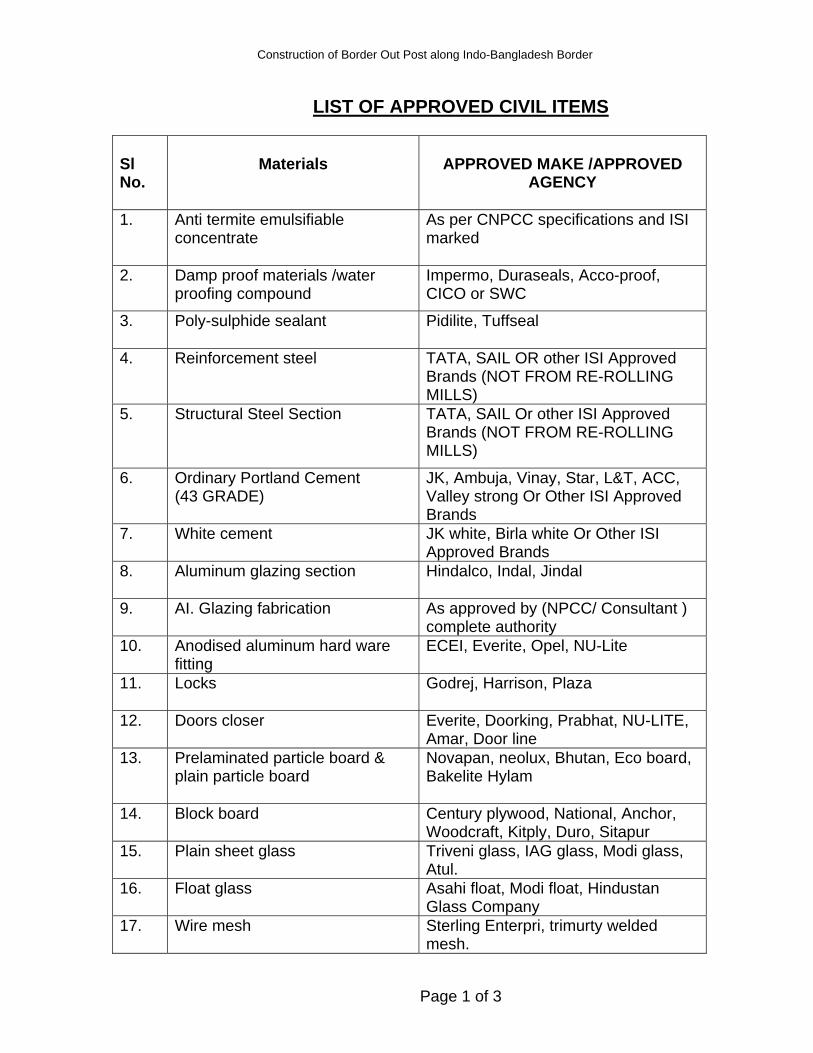
Construction of Border Out Post along Indo-Bangladesh Border
Page 1 of 3
LIST OF APPROVED CIVIL ITEMS Sl No.
Materials
APPROVED MAKE /APPROVED
AGENCY
1. Anti termite emulsifiable concentrate
As per CNPCC specifications and ISI marked
2. Damp proof materials /water proofing compound
Impermo, Duraseals, Acco-proof, CICO or SWC
3. Poly-sulphide sealant
Pidilite, Tuffseal
4. Reinforcement steel
TATA, SAIL OR other ISI Approved Brands (NOT FROM RE-ROLLING MILLS)
5. Structural Steel Section
TATA, SAIL Or other ISI Approved Brands (NOT FROM RE-ROLLING MILLS)
6. Ordinary Portland Cement (43 GRADE)
JK, Ambuja, Vinay, Star, L&T, ACC, Valley strong Or Other ISI Approved Brands
7. White cement
JK white, Birla white Or Other ISI Approved Brands
8. Aluminum glazing section
Hindalco, Indal, Jindal
9. AI. Glazing fabrication
As approved by (NPCC/ Consultant ) complete authority
10. Anodised aluminum hard ware fitting
ECEI, Everite, Opel, NU-Lite
11. Locks
Godrej, Harrison, Plaza
12. Doors closer
Everite, Doorking, Prabhat, NU-LITE, Amar, Door line
13. Prelaminated particle board & plain particle board
Novapan, neolux, Bhutan, Eco board, Bakelite Hylam
14. Block board
Century plywood, National, Anchor, Woodcraft, Kitply, Duro, Sitapur
15. Plain sheet glass
Triveni glass, IAG glass, Modi glass, Atul.
16. Float glass
Asahi float, Modi float, Hindustan Glass Company
17. Wire mesh
Sterling Enterpri, trimurty welded mesh.
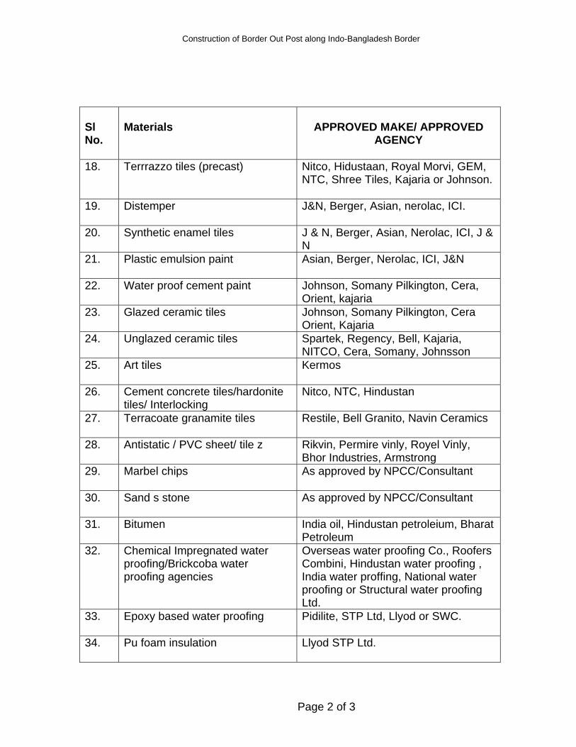
Construction of Border Out Post along Indo-Bangladesh Border
Page 2 of 3
Sl No.
Materials
APPROVED MAKE/ APPROVED
AGENCY
18. Terrrazzo tiles (precast)
Nitco, Hidustaan, Royal Morvi, GEM, NTC, Shree Tiles, Kajaria or Johnson.
19. Distemper
J&N, Berger, Asian, nerolac, ICI.
20. Synthetic enamel tiles J & N, Berger, Asian, Nerolac, ICI, J & N
21. Plastic emulsion paint
Asian, Berger, Nerolac, ICI, J&N
22. Water proof cement paint Johnson, Somany Pilkington, Cera, Orient, kajaria
23. Glazed ceramic tiles Johnson, Somany Pilkington, Cera Orient, Kajaria
24. Unglazed ceramic tiles Spartek, Regency, Bell, Kajaria, NITCO, Cera, Somany, Johnsson
25. Art tiles
Kermos
26. Cement concrete tiles/hardonite tiles/ Interlocking
Nitco, NTC, Hindustan
27. Terracoate granamite tiles
Restile, Bell Granito, Navin Ceramics
28. Antistatic / PVC sheet/ tile z Rikvin, Permire vinly, Royel Vinly, Bhor Industries, Armstrong
29. Marbel chips
As approved by NPCC/Consultant
30. Sand s stone
As approved by NPCC/Consultant
31. Bitumen India oil, Hindustan petroleium, Bharat Petroleum
32. Chemical Impregnated water proofing/Brickcoba water proofing agencies
Overseas water proofing Co., Roofers Combini, Hindustan water proofing , India water proffing, National water proofing or Structural water proofing Ltd.
33. Epoxy based water proofing
Pidilite, STP Ltd, Llyod or SWC.
34. Pu foam insulation
Llyod STP Ltd.
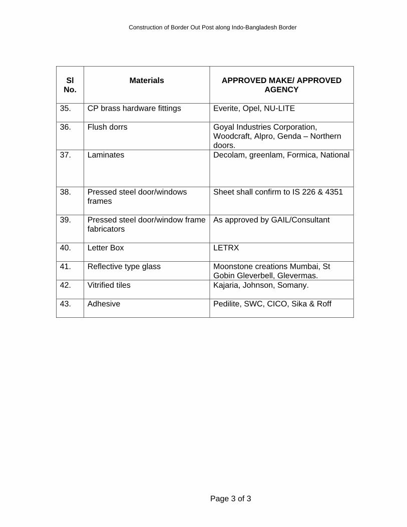
Construction of Border Out Post along Indo-Bangladesh Border
Page 3 of 3
Sl
No.
Materials
APPROVED MAKE/ APPROVED
AGENCY
35. CP brass hardware fittings
Everite, Opel, NU-LITE
36. Flush dorrs Goyal Industries Corporation, Woodcraft, Alpro, Genda – Northern doors.
37. Laminates
Decolam, greenlam, Formica, National
38. Pressed steel door/windows frames
Sheet shall confirm to IS 226 & 4351
39. Pressed steel door/window frame fabricators
As approved by GAIL/Consultant
40. Letter Box
LETRX
41. Reflective type glass
Moonstone creations Mumbai, St Gobin Gleverbell, Glevermas.
42. Vitrified tiles
Kajaria, Johnson, Somany.
43. Adhesive
Pedilite, SWC, CICO, Sika & Roff
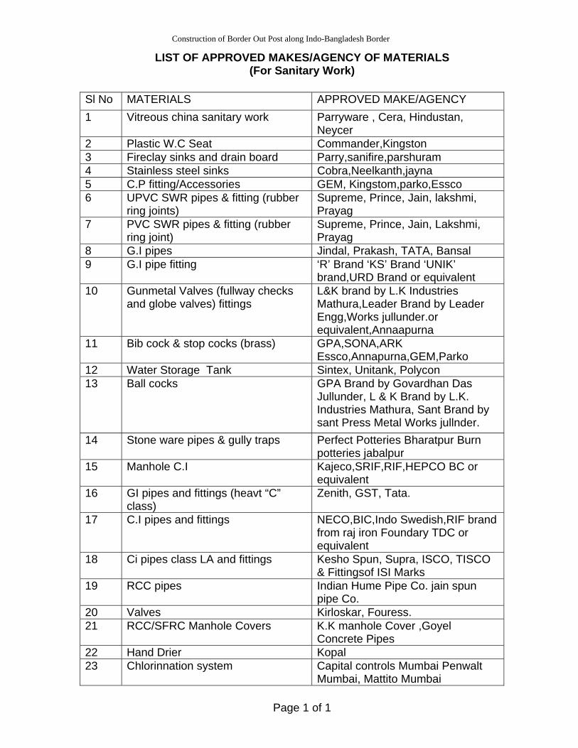
Construction of Border Out Post along Indo-Bangladesh Border
Page 1 of 1
LIST OF APPROVED MAKES/AGENCY OF MATERIALS (For Sanitary Work)
Sl No MATERIALS APPROVED MAKE/AGENCY 1 Vitreous china sanitary work Parryware , Cera, Hindustan,
Neycer 2 Plastic W.C Seat Commander,Kingston 3 Fireclay sinks and drain board Parry,sanifire,parshuram 4 Stainless steel sinks Cobra,Neelkanth,jayna 5 C.P fitting/Accessories GEM, Kingstom,parko,Essco 6 UPVC SWR pipes & fitting (rubber
ring joints) Supreme, Prince, Jain, lakshmi, Prayag
7 PVC SWR pipes & fitting (rubber ring joint)
Supreme, Prince, Jain, Lakshmi, Prayag
8 G.I pipes Jindal, Prakash, TATA, Bansal 9 G.I pipe fitting ‘R’ Brand ‘KS’ Brand ‘UNIK’
brand,URD Brand or equivalent 10 Gunmetal Valves (fullway checks
and globe valves) fittings L&K brand by L.K Industries Mathura,Leader Brand by Leader Engg,Works jullunder.or equivalent,Annaapurna
11 Bib cock & stop cocks (brass) GPA,SONA,ARK Essco,Annapurna,GEM,Parko
12 Water Storage Tank Sintex, Unitank, Polycon 13 Ball cocks GPA Brand by Govardhan Das
Jullunder, L & K Brand by L.K. Industries Mathura, Sant Brand by sant Press Metal Works jullnder.
14 Stone ware pipes & gully traps Perfect Potteries Bharatpur Burn potteries jabalpur
15 Manhole C.I Kajeco,SRIF,RIF,HEPCO BC or equivalent
16 GI pipes and fittings (heavt “C” class)
Zenith, GST, Tata.
17 C.I pipes and fittings NECO,BIC,Indo Swedish,RIF brand from raj iron Foundary TDC or equivalent
18 Ci pipes class LA and fittings Kesho Spun, Supra, ISCO, TISCO & Fittingsof ISI Marks
19 RCC pipes Indian Hume Pipe Co. jain spun pipe Co.
20 Valves Kirloskar, Fouress. 21 RCC/SFRC Manhole Covers K.K manhole Cover ,Goyel
Concrete Pipes 22 Hand Drier Kopal 23 Chlorinnation system Capital controls Mumbai Penwalt
Mumbai, Mattito Mumbai
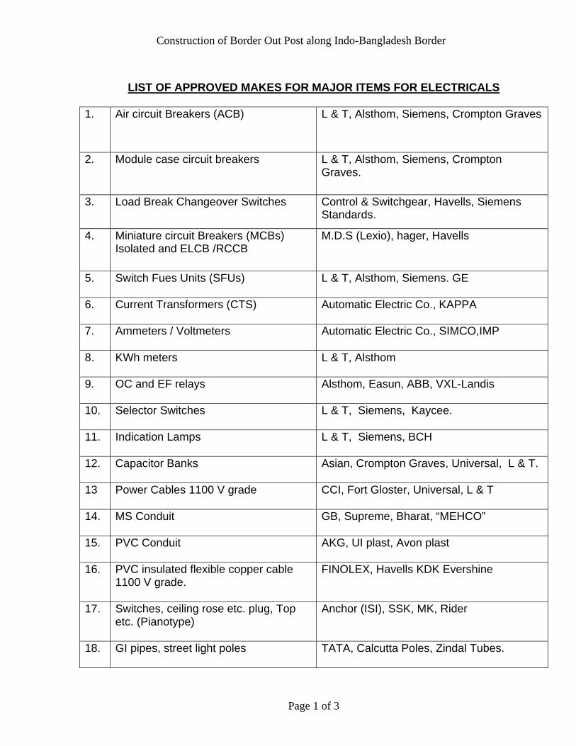
Construction of Border Out Post along Indo-Bangladesh Border
Page 1 of 3
LIST OF APPROVED MAKES FOR MAJOR ITEMS FOR ELECTRICALS
1. Air circuit Breakers (ACB) L & T, Alsthom, Siemens, Crompton Graves
2. Module case circuit breakers L & T, Alsthom, Siemens, Crompton Graves.
3. Load Break Changeover Switches Control & Switchgear, Havells, Siemens Standards.
4. Miniature circuit Breakers (MCBs) Isolated and ELCB /RCCB
M.D.S (Lexio), hager, Havells
5. Switch Fues Units (SFUs)
L & T, Alsthom, Siemens. GE
6. Current Transformers (CTS)
Automatic Electric Co., KAPPA
7. Ammeters / Voltmeters
Automatic Electric Co., SIMCO,IMP
8. KWh meters
L & T, Alsthom
9. OC and EF relays
Alsthom, Easun, ABB, VXL-Landis
10. Selector Switches
L & T, Siemens, Kaycee.
11. Indication Lamps
L & T, Siemens, BCH
12. Capacitor Banks
Asian, Crompton Graves, Universal, L & T.
13 Power Cables 1100 V grade
CCI, Fort Gloster, Universal, L & T
14. MS Conduit
GB, Supreme, Bharat, “MEHCO”
15. PVC Conduit
AKG, UI plast, Avon plast
16. PVC insulated flexible copper cable 1100 V grade.
FINOLEX, Havells KDK Evershine
17. Switches, ceiling rose etc. plug, Top etc. (Pianotype)
Anchor (ISI), SSK, MK, Rider
18. GI pipes, street light poles
TATA, Calcutta Poles, Zindal Tubes.
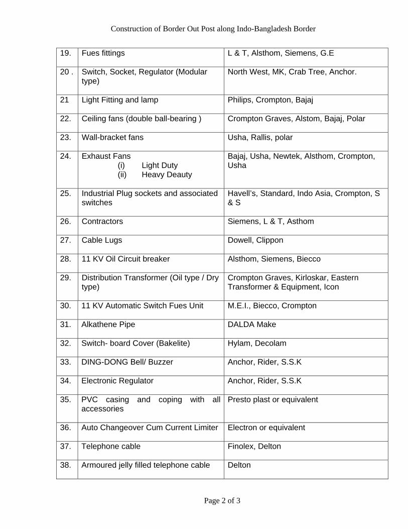
Construction of Border Out Post along Indo-Bangladesh Border
Page 2 of 3
19. Fues fittings
L & T, Alsthom, Siemens, G.E
20 . Switch, Socket, Regulator (Modular type)
North West, MK, Crab Tree, Anchor.
21 Light Fitting and lamp
Philips, Crompton, Bajaj
22. Ceiling fans (double ball-bearing )
Crompton Graves, Alstom, Bajaj, Polar
23. Wall-bracket fans
Usha, Rallis, polar
24. Exhaust Fans (i) Light Duty (ii) Heavy Deauty
Bajaj, Usha, Newtek, Alsthom, Crompton, Usha
25. Industrial Plug sockets and associated switches
Havell’s, Standard, Indo Asia, Crompton, S & S
26. Contractors
Siemens, L & T, Asthom
27. Cable Lugs
Dowell, Clippon
28. 11 KV Oil Circuit breaker
Alsthom, Siemens, Biecco
29. Distribution Transformer (Oil type / Dry type)
Crompton Graves, Kirloskar, Eastern Transformer & Equipment, Icon
30. 11 KV Automatic Switch Fues Unit
M.E.I., Biecco, Crompton
31. Alkathene Pipe
DALDA Make
32. Switch- board Cover (Bakelite)
Hylam, Decolam
33. DING-DONG Bell/ Buzzer
Anchor, Rider, S.S.K
34. Electronic Regulator
Anchor, Rider, S.S.K
35. PVC casing and coping with all accessories
Presto plast or equivalent
36. Auto Changeover Cum Current Limiter
Electron or equivalent
37. Telephone cable
Finolex, Delton
38. Armoured jelly filled telephone cable
Delton
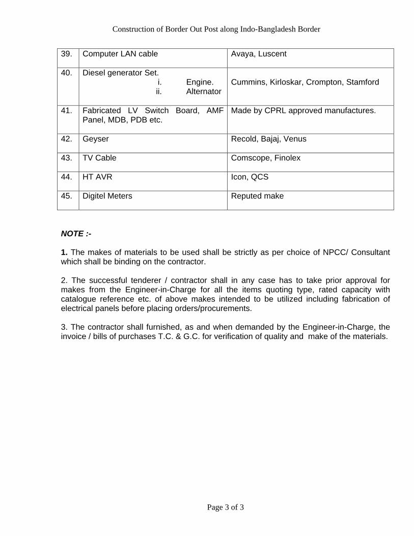
Construction of Border Out Post along Indo-Bangladesh Border
Page 3 of 3
39. Computer LAN cable
Avaya, Luscent
40. Diesel generator Set. i. Engine. ii. Alternator
Cummins, Kirloskar, Crompton, Stamford
41. Fabricated LV Switch Board, AMF Panel, MDB, PDB etc.
Made by CPRL approved manufactures.
42. Geyser
Recold, Bajaj, Venus
43. TV Cable
Comscope, Finolex
44. HT AVR
Icon, QCS
45. Digitel Meters
Reputed make
NOTE :- 1. The makes of materials to be used shall be strictly as per choice of NPCC/ Consultant which shall be binding on the contractor. 2. The successful tenderer / contractor shall in any case has to take prior approval for makes from the Engineer-in-Charge for all the items quoting type, rated capacity with catalogue reference etc. of above makes intended to be utilized including fabrication of electrical panels before placing orders/procurements. 3. The contractor shall furnished, as and when demanded by the Engineer-in-Charge, the invoice / bills of purchases T.C. & G.C. for verification of quality and make of the materials.
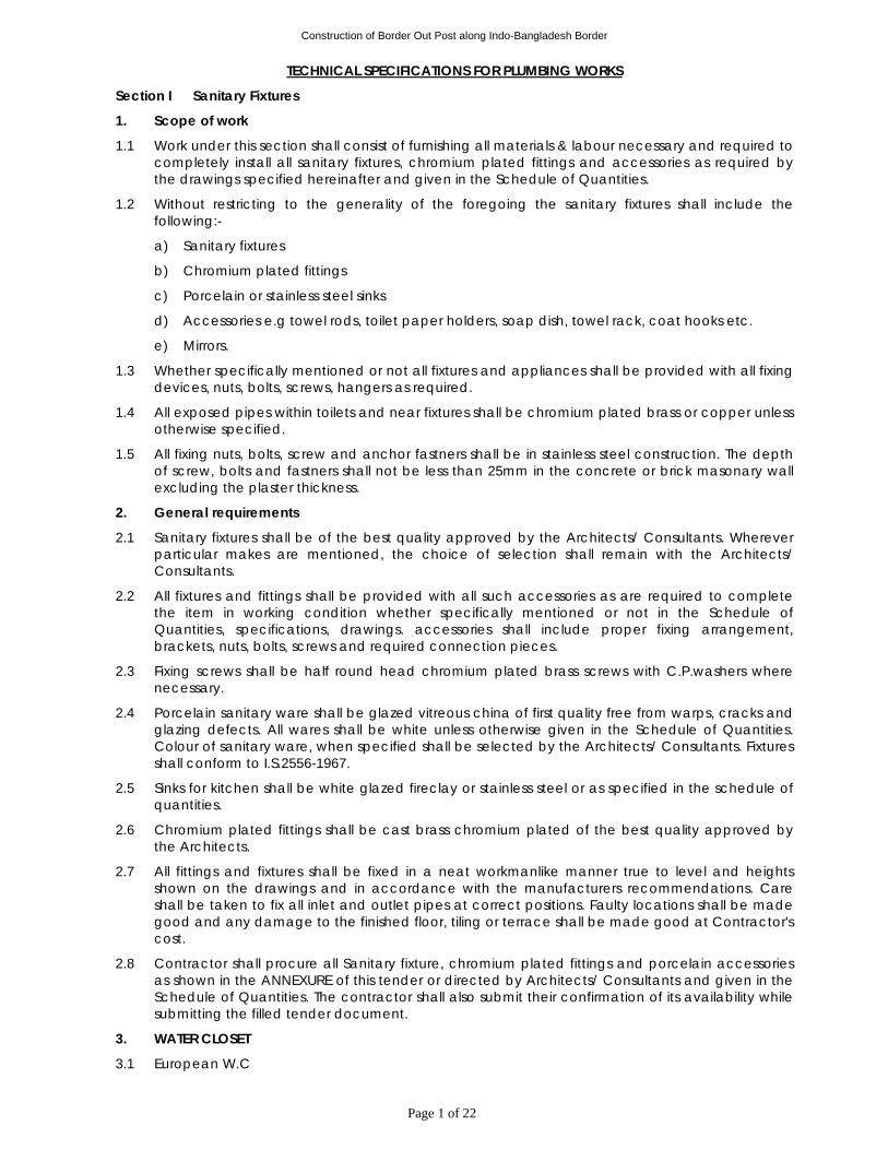
Construction of Border Out Post along Indo-Bangladesh Border
Page 1 of 22
TECHNICAL SPECIFICATIONS FOR PLUMBING WORKS
Section I Sanitary Fixtures
1. Scope of work
1.1 Work under this section shall consist of furnishing all materials & labour necessary and required to completely install all sanitary fixtures, chromium plated fittings and accessories as required by the drawings specified hereinafter and given in the Schedule of Quantities.
1.2 Without restricting to the generality of the foregoing the sanitary fixtures shall include the following:-
a) Sanitary fixtures
b) Chromium plated fittings
c) Porcelain or stainless steel sinks
d) Accessories e.g towel rods, toilet paper holders, soap dish, towel rack, coat hooks etc.
e) Mirrors.
1.3 Whether specifically mentioned or not all fixtures and appliances shall be provided with all fixing devices, nuts, bolts, screws, hangers as required.
1.4 All exposed pipes within toilets and near fixtures shall be chromium plated brass or copper unless otherwise specified.
1.5 All fixing nuts, bolts, screw and anchor fastners shall be in stainless steel construction. The depth of screw, bolts and fastners shall not be less than 25mm in the concrete or brick masonary wall excluding the plaster thickness.
2. General requirements
2.1 Sanitary fixtures shall be of the best quality approved by the Architects/ Consultants. Wherever particular makes are mentioned, the choice of selection shall remain with the Architects/ Consultants.
2.2 All fixtures and fittings shall be provided with all such accessories as are required to complete the item in working condition whether specifically mentioned or not in the Schedule of Quantities, specifications, drawings. accessories shall include proper fixing arrangement, brackets, nuts, bolts, screws and required connection pieces.
2.3 Fixing screws shall be half round head chromium plated brass screws with C.P.washers where necessary.
2.4 Porcelain sanitary ware shall be glazed vitreous china of first quality free from warps, cracks and glazing defects. All wares shall be white unless otherwise given in the Schedule of Quantities. Colour of sanitary ware, when specified shall be selected by the Architects/ Consultants. Fixtures shall conform to I.S.2556-1967.
2.5 Sinks for kitchen shall be white glazed fireclay or stainless steel or as specified in the schedule of quantities.
2.6 Chromium plated fittings shall be cast brass chromium plated of the best quality approved by the Architects.
2.7 All fittings and fixtures shall be fixed in a neat workmanlike manner true to level and heights shown on the drawings and in accordance with the manufacturers recommendations. Care shall be taken to fix all inlet and outlet pipes at correct positions. Faulty locations shall be made good and any damage to the finished floor, tiling or terrace shall be made good at Contractor's cost.
2.8 Contractor shall procure all Sanitary fixture, chromium plated fittings and porcelain accessories as shown in the ANNEXURE of this tender or directed by Architects/ Consultants and given in the Schedule of Quantities. The contractor shall also submit their confirmation of its availability while submitting the filled tender document.
3. WATER CLOSET
3.1 European W.C
Construction of Border Out Post along Indo-Bangladesh Border
Page 2 of 22
3.1.1 European W.C.shall be low volume flushing (3-6 litres) Wall mounting type with ‘P’ trap, set flushed by means of concealed flush valve. The flush pipe/bend shall be connected to the W.C. by means of a suitable rubber adaptor.
3.1.2 Each W.C. set shall be provided with a solid plastic seat of colour given in the schedule of quantities, rubber buffers and chromium plated hinges.
3.1.3 Plastic seat shall be so fixed that it remains absolutely stationary in vertical position without falling down on the W.C.
3.1.4 Each W.C. set shall be fixed by mounting arrangement as per manufacturer recommendation as specified in the schedule of quantity. NO FABRICATED MOUNTING ARRANGEMENT SHALL BE ALLOWED AT SITE for fixing of W.C.
3.2 Indian W.C.
3.2.1 Indian Water Closet shall be floor mounted Orissa pattern set flushed by means of an exposed or concealed type flush valve as given in schedule of quantites. Flush pipe/bend shall be connected to the W.C. by means of a suitable rubber adaptor.
4. Lavatory basin
4.1 Lavatory basins shall be glazed vitreous china of size, colour, shape and type specified in the Schedule of Quantities.
4.2 Each basin shall be provided with R.S. or C.I. brackets and clips and the basin securely fixed to wall as per manufacturer recommendation. Placing of basins over the brackets without secure fixing or site fabricated brackets shall not be accepted.
4. Each basin shall be provided with 32 mm dia C.P.washers as specified in the Schedule of Quantities, 32 mm dia C.P. brass bottle trap with C.P.pipe to wall and flange.
4.4 Each basin shall be provided with mixing fitting or as specified in the Schedule of Quantities.
4.5 Basins shall be fixed at proper heights as shown on drawings. If height is not specified, the rim level shall be 79 cms or as directed by Architects/ Consultants.
5. Sinks
5.1 Sinks shall be stainless steel or any other material as specified in the Schedule of Quantities.
5.2 Each sink shall be provided with R.S. or C.I.brackets and clips and securely fixed. Counter top sinks shall be fixed with suitable angle iron brackets or clips as recommended by the manufacturer. Each sink shall be provided with 40 mm dia C.P. waste with chain and plug as given in the Schedule of Quantities. Fixing shall be done as directed by Architects/ Consultants.
5.3 Supply fittings for sinks shall be mixing fittings or C.P.taps as specified in the Schedule of Quantities.
6. Accessories
6.1 Contractor shall install all chromium plated and porcelain accessories as shown on the drawings or directed by Architects/ Consultants and given in the Schedule of Quantities.
6.2 All C.P. accessories shall be fixed with C.P. brass half round head screws and cup washers in wall with rawl plugs or nylon sleeves and shall include cutting and making good as required or directed by Architects/ Consultants.
6.3 Porcelain accessories shall be fixed in walls and set in cement mortar 1:2 (1 cement: 2 coarse sand) and fixed in relation to the tiling work.
7. Measurement
7.1 Sanitary fixtures shall be measured by numbers.
7.2 Rate for providing and fixing of sanitary fixtures, accessories etc. and shall include all items, and operations stated in the respective specifications and Schedule of Quantities and nothing extra is payable.
7.3 Rates for all items under specifications paras above shall be inclusive of cutting holes and chases and making good the same, C.P.brass screws, nuts, bolts and any fixing arrangements required and recommended by manufacturers, testing and commissioning.
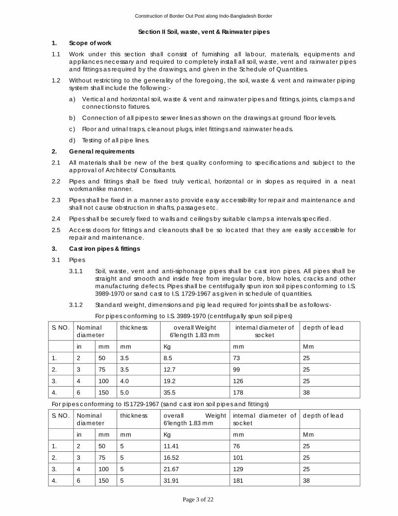
Construction of Border Out Post along Indo-Bangladesh Border
Page 3 of 22
Section II Soil, waste, vent & Rainwater pipes
1. Scope of work
1.1 Work under this section shall consist of furnishing all labour, materials, equipments and appliances necessary and required to completely install all soil, waste, vent and rainwater pipes and fittings as required by the drawings, and given in the Schedule of Quantities.
1.2 Without restricting to the generality of the foregoing, the soil, waste & vent and rainwater piping system shall include the following:-
a) Vertical and horizontal soil, waste & vent and rainwater pipes and fittings, joints, clamps and connections to fixtures.
b) Connection of all pipes to sewer lines as shown on the drawings at ground floor levels.
c) Floor and urinal traps, cleanout plugs, inlet fittings and rainwater heads.
d) Testing of all pipe lines.
2. General requirements
2.1 All materials shall be new of the best quality conforming to specifications and subject to the approval of Architects/ Consultants.
2.2 Pipes and fittings shall be fixed truly vertical, horizontal or in slopes as required in a neat workmanlike manner.
2.3 Pipes shall be fixed in a manner as to provide easy accessibility for repair and maintenance and shall not cause obstruction in shafts, passages etc.
2.4 Pipes shall be securely fixed to walls and ceilings by suitable clamps a intervals specified.
2.5 Access doors for fittings and cleanouts shall be so located that they are easily accessible for repair and maintenance.
3. Cast iron pipes & fittings
3.1 Pipes
3.1.1 Soil, waste, vent and anti-siphonage pipes shall be cast iron pipes. All pipes shall be straight and smooth and inside free from irregular bore, blow holes, cracks and other manufacturing defects. Pipes shall be centrifugally spun iron soil pipes conforming to I.S. 3989-1970 or sand cast to I.S. 1729-1967 as given in schedule of quantities.
3.1.2 Standard weight, dimensions and pig lead required for joints shall be as follows:-
For pipes conforming to I.S. 3989-1970 (centrifugally spun soil pipes)
S. NO. Nominal diameter
thickness overall Weight 6'length 1.83 mm
internal diameter of socket
depth of lead
in mm mm Kg mm Mm
1. 2 50 3.5 8.5 73 25
2. 3 75 3.5 12.7 99 25
3. 4 100 4.0 19.2 126 25
4. 6 150 5.0 35.5 178 38
For pipes conforming to IS 1729-1967 (sand cast iron soil pipes and fittings)
S. NO. Nominal diameter
thickness overall Weight 6'length 1.83 mm
internal diameter of socket
depth of lead
in mm mm Kg mm Mm
1. 2 50 5 11.41 76 25
2. 3 75 5 16.52 101 25
3. 4 100 5 21.67 129 25
4. 6 150 5 31.91 181 38
Construction of Border Out Post along Indo-Bangladesh Border
Page 4 of 22
3.1.3 Tolerance: Acceptable tolerance for pipes to IS : 3989 and IS : 1729 shall be as follows:- a) Wall thickness -15%
b) Length +/- 20 mm
c) Weight -10%
4. uPVC pipes & fittings“ [For Rainwater Piping]
4.1 Pipes
4.1.1 uPVC pipes for drainage system shall be un-plasticized (rigid) PVC pipes conforming to I.S.: 13592 Class A or as specified in schedule of quantities.
4.1.2 Fittings for the pipes shall be injection moulded with approved type of sockets and 'O' rings joints/solvent welded joints as per recommendations of the manufacturers.
4.1.3 Jointing shall be done as per the manufacturers recommendation. The pipes and fittings must have matching dimensions for a perfect joint. Loose or excessively tight joints in the system shall not be accepted. Fittings must have sufficient gap (approx. 10 mm) for permissible thermal expansion of pipes.
4.1.4 uPVC pipes shall be clamped to the wall with approved type uPVC saddle clamps.
4.2 Fittings
4.2.1 Fittings shall conform to the same Indian Standard as for pipes. Contractor shall use pipes and fittings of matching specifications.
4.2.2 Fittings shall be of the required degree of curvature with or without access door.
4.2.3 Access door shall be made up with 3 mm thick insertion rubber washer and white lead. The bolts shall be lubricated with grease or white lead for easy removal later. The fixing shall be air and water tight.
4.3 Fixing
4.3.1 All vertical pipes shall be fixed by M.S. clamps truly vertical. Branch pipes shall be connected to the stack at the same angle as that of the fittings. No collars shall be used on vertical stacks. Each stack shall be terminated at top with a cowl (terminal guard).
4.3.2 Horizontal pipes running along ceiling shall be fixed on structural adjustable clamps of special design shown on the drawings or as directed. Horizontal pipes shall be laid to uniform slope and the clamps adjusted to the proper levels so that the pipes fully rest on them.
4.3.3 Contractor shall provide all sleeves, openings, hangers, inserts during the construction. He shall provide all necessary information to the building Contractor for making such ovisions in the structure as necessary. All damages shall be made good to restore the surfaces.
5. Clamps
5.1 Holder bat clamps shall be of standard design and fabricated from M.S. flats 40x3 mm thick and 12 mm dia M.S. Rod and 6 mm nuts and bolts. They shall be painted with two coats of black bitumen paint before fixing. Holder bat clamps shall be fixed in cement concrete 1:2:4 mix blocks 10x10x10 cms deep.
5.2 Where holder bat clamps are to be fixed in RCC column or slotted angles, walls or beam they shall be fixed with 40x3 mm flat iron "U" type clamps with anchor fasteners of approved design or 6 mm nuts and bolts.
5.3 Structural clamps shall be fabricated from M.S. structural members e.g. rods, angles, channels flats as per detailed drawing or as directed. Contractor shall provide all nuts, bolts, welding material and paint the clamps with one coat of red oxide and two or more coats of black enamel paint.
5.4. Slotted angle/channel supports on walls shall be provided wherever shown on drawings. Angles/channels shall be of sizes shown on drawings or specified in schedule of quantities. Angles/channels shall be fixed to brick walls with bolts embedded in cement concrete blocks
Construction of Border Out Post along Indo-Bangladesh Border
Page 5 of 22
and to RCC walls with suitable anchor fasteners. The spacing of support bolts horizontally shall not exceed 1 m.
5.5 Wherever M.S. clamps are required to be anchored directly to brick walls, concrete slabs, beams or columns, nothing extra shall be payable for clamping arrangement and making good with cement concrete 1:2:4 mix (1 cement :2 coarse sand :4 mm stone aggregate 20 mm nominal size) as directed by the Architects/ Consultants.
6. Traps
6.1 Nahni trap or floor traps: Nahni traps or floor traps shall be cast iron, deep seal with an effective seal of 50 mm. The trap and waste pipes shall be set in cement concrete blocks firmly supported on the structural floor. The blocks shall be in 1:2:4 mix (1 cement :2 coarse sand :4 stone aggregate 20 mm nominal size) and extended to 40 mm below finished floor level. Contractor shall provide all necessary shuttering and centering for the blocks. Size of the block shall be 30x30 cms of the required depth.
6.2 Urinal traps: Urinal traps shall be cast iron P or S traps with or without vent and set in cement concrete block specified in Para above without extra charge.
6.3 Floor trap inlet: Bath room traps and connections shall ensure free and silent flow of discharging water. Where specified, Contractor shall provide a special type Galvanized iron inlet fitting hooper fabricated from 100 mm GI (IS:1239 -Medium class) pipe without or with one, two or three inlet sockets to receive the waste pipe (s). Joint between waste and hopper inlet socket shall be lead caulked. Hopper shall be connected to a C.I. P or S trap with at least 50 mm seal (hopper and traps shall be paid for separately.)Floor trap inlet hoppers and the traps shall be set in cement concrete blocks as specified in Para above without extra charge.
6.4 Floor Trap Grating: Floor and urinal traps shall be provided with 75-150mm square or round C.P./Stainless steel grating, with rim of approved design and shape. Minimum thickness shall be 4 mm (for C.P. brass) or 1.2 mm (for SS), as specified in the Schedule of Quantities.
7. Jointing
7.1 Soil, waste vent, anti-syphonage and rainwater pipes shall be jointed with refined pig lead conforming to I.S.27-1977. leave a minimum space for the pig lead as given in Para 3.1.2 to be poured in. After the pouring the lead shall be caulked into the joint with caulking tool and hammer. all surplus lead shall be cut and joint left flush with the rim of the socket neatly.
8. Cleanout plugs
8.1 Contractor shall provide cast brass cleanout plugs as required. Cleanout plugs shall be threaded and provided with key holes for opening . Cleanout plugs shall be fixed to the pipe by a G.I. socket and lead caulked joint.
9. Waste pipe from appliances
9.1 Waste pipe from appliances e.g. washbasins, sinks and urinals shall be of galvanized steel or P.V.C. as given in the Schedule of Quantities.
9.2 All pipes shall be fixed in gradient towards the outfalls of drains. Pipes inside a toilet room shall be in chase unless otherwise shown on drawings. Where required pipes may be run at ceiling level in suitable gradient and supported on structural clamps. Spacing for clamps for such pipes shall be as follows:-
Vertical Horizontal
G.I. pipes 300 cms 240 cms
P.V.C. pipes 180 cms 120 cms
9.3 Galvanized pipes: Pipes shall be galvanized steel tubes conforming to I.S.1239-1979 (medium class) and quality certificates shall be furnished. Pipes shall be provided with all required fittings e.g. tees, couplings, bends, elbows, unions, reducers, nipples, plugs. All G.I. waste pipes shall be terminated at the point of connection with the appliance with an outlet of suitable diameter. Pipes in chase shall be painted with two coats of black bitumen paint and exposed pipes with one coat of red oxide primer and two or more coats of synthetic enamel paint or as given in the Schedule of Quantities.
Construction of Border Out Post along Indo-Bangladesh Border
Page 6 of 22
10. Khurras
10.1 The khurras shall be constructed before the brick masonary work in parapet wall is taken up and it shall be 45cmx45cm unless otherwise specified in the description of the item and shall be formed of cement concrete 1:2:4 mix (1 cement: 2 coarse sand: 4 graded stone aggregate 20 mm nominal size ) or other mix as stipulated in the description of the item.
10.2 Laying:
10.2.1 A PVC sheet 1mx1mx400 micron shall be laid under the khurras and then cement concrete shall be laid over it to average thickness of 50mm with its top surface lower than the level of adjoining roof surface by not less than
a) 20mm in case of roof surface finished with lime concrete terracing.
b) 70 mm in case of roof surface finished with lime concrete terracing covered with brick tiles.
c) 50mm in case of roof surface finished with mud phuska with brick tile covering.
10.2.2 The concrete shall be laid to a size greater than the stipulated size of the khurras in such a way that the adjoining terracing whether of lime concrete or of the tile brick shall overlap the concrete on its three edges by not less than 7.5 cm. The concrete will slope uniformly from the edges to the outlets the slope as being as much as possible and in no case less than 20mm cement concrete at outlet. The concrete shall be continued at the same slope through the width of the wall into the outlet opening to ensure a water tight joint.
10.2.3 The khurras and the side of the outlet shall than be rendered with 12mm coat of cement plaster 1:3 mix ( (1 cement:3 coarse sand) or other mix as stipulated in the description of the item. This shall be done when the concrete is still green and shall be finished with floating coat of neat cement. The sides of the khurras and the sides of the outlet opening shall be well rounded. The size of the finished outlet opening shall be 10cm wide by 20 cm high or as directed by Engineer -in-charge.
10.2.4 As a safeguard against choking of rainwater outlet through rain water pipes at terrace level, Cast Iron rainwater outlet fitting with aluminium ring and aluminium domical head (fixed with SS screw) of size 250x100 mm shall be provided as directed by the Engineer in-Charge.
11. Cast iron pipes for drainage
11.1 All drainage lines passing under building, floors, in exposed position above ground e.g. basement ceiling shall be cast iron pipes. Position of such pipes shall generally be shown on the drawings.
11.2 Cast iron pipes shall be centrifugally spun iron pipes conforming to I.S. 1536-1967. Quality certificates shall be furnished.
11.3 Fittings
a) Fittings used for C.I. drainage pipe shall conform to I.S.1538-1967. Wherever possible junction from branch pipes shall be made by a Y tee.
b) Cleanout plugs shall be provided on head of each drain and at location indicated on plans or directed by Architects/ Consultants. Cleanout plugs shall be of size matching the full bore of the pipe. Plugs shall be made out with G.I. coupling caulked into the socket of the pipe or fittings. The end shall be provided with a brass screwed plug with suitable key for opening.
11.4 Laying
a) All cast iron pipes and fittings shall be jointed with best quality soft pig lead (conforming to I.S. 27-1977) which shall be free from impurities. in wet trenches joints shall be made from lead wool. Nothing extra will be paid for lead wool joints. Depth of pig lead and weight for joints shall be as per I.S. code.
b) The spigot of pipe or fittings shall be centered in the adjoining socket by caulking. Sufficient turns of tarred gaskin will be given to leave unfilled the required depth of socket for depth of 45 mm when the gaskin has been caulked tightly home. Joining ring shall be placed round the barrel and against the face of the socket. Molten pig lead shall then be
Construction of Border Out Post along Indo-Bangladesh Border
Page 7 of 22
poured to fill the remainder of the socket. This shall then be done in one pouring. The lead shall then be solidly caulked with suitable tools and hammers weighing not less than 2 kg.
c) For lead wool joints the socket shall be caulked with tarred gaskin, as explained above. The lead wool shall be inserted into the sockets and tightly caulked home skein by skein with suitable tools and hammers of not less than 2 kg weight until joint is filled.
11.5 Testing: All cast iron pipes for drainage shall be tested to a hydraulic test of 3 meter head. A test register shall be maintained which shall be signed and dated by Contractor, Architects/ Consultants and representative of Architect/Consultant.
12. Cement Concrete
12.1 Cast iron soil and waste pipes under floor in sunken slabs and in wall chases (when cut specially for the pipe) shall be encased in cement concrete 1:2:4 mix ( 1 cement :2 coarse sand :4 stone aggregate 12 mm size) 75 mm in bed and all-round. When pipes are running well above the structural slab, the encased pipes shall be supported with suitable cement concrete pillars of required height at intervals of 1.8 m. Rate for concrete round pipes shall be inclusive of pillars, supports, shuttering and centering.
13. Painting
13.1 Soil, waste vent, anti-syphonage and rainwater pipes in exposed location in shafts and pipe spaces shall be painted with two or more coats of synthetic enamel paint to give an even shade.
13.2 Paint shall be of approved quality and shade. Where directed pipes shall be painted in accordance with approved pipe colour code.
13.3 G.I. waste pipes in chase shall be painted with two coats of bitumen paint, covered with polythene tape and a final coat of bitumen paint. Exposed pipes shall be painted with two or more coats of synthetic enamel paint.
13.4 C.I. soil and waste pipes below ground and covered in cement concrete or lead pipes shall not be painted.
14. Cutting and making good
14.1 Pipes shall be fixed and tested as building proceeds. Contractor shall provide all necessary holes cut outs and chases in structural members as building work proceeds. wherever holes are cut or left originally, they shall be made good with cement concrete 1:2:4 (1 cement: 2 coarse sand: 4 stone aggregate 20 mm nominal size) or cement mortar 1:2 (1 cement: 2 coarse sand) and the surface restored as in original condition.
15. Testing
15.1 Before use at site all C.I. soil pipes shall be tested by filling up with water for at least 10 minutes. After filling, pipes shall be struck with a hammer and inspected for blow holes and cracks. All defective pipes shall be rejected and removed from the site within 48 hours. Pipes with minor sweating may be accepted at the discretion of the Architects/ Consultants.
15.2 Pipes shall be tested after installation, by filling up the stack with water. All opening and connections shall be suitably plugged. The total head in the stack shall be however not exceed 3 m.
15.3 Alternatively Contractor may test all soil and waste stacks by a smoke testing machine. Smoke shall be pumped into the stack after plugging all inlets and connections. The top end shall, however, be left open. The stack shall then be observed for leakages and all defective pipes and fittings removed or repaired as directed by the Architects/ Consultants.
15.4 A test register shall be maintained and all entries shall be signed and dated by Contractors and Architects/ Consultants.
16. Measurements
16.1 General
16.1.1 Rates for all items quoted shall be inclusive of all work and items given in the above mentioned specifications and Schedule of Quantities and applicable for the work under floors, in shafts or at ceiling level at all heights and depths.
Construction of Border Out Post along Indo-Bangladesh Border
Page 8 of 22
16.1.2 All rates are inclusive of cutting holes and chases in RCC and masonry work and making good the same.
16.1.3 All rates are inclusive of pre testing and on site testing of the installations, materials and commissioning.
16.2 Pipes (Unit of measurement: Linear meter to the nearest centimeter)
16.2.1. All uPVC & C.I. soil, waste, vent, anti-syphonage and rain water pipes shall be measured net when fixed correct to a centimeter including all fittings along its length. No allowance shall be made for the portions of pipe lengths entering the sockets of the adjacent pipes or fittings. The above will apply to both case i.e. whether pipes are fixed on wall face or pillars or embedded in masonry or pipes running at ceiling level.
16.2.2 G.I., pipes shall measured per running metre correct to a centimeter for the finished work which shall include fittings e.g. bends, tees, elbows, reducers, crosses, sockets, nipples and nuts. The length shall be taken along centre line of the pipes and fittings. All pipes and fittings shall be classified according to their diameter, method of jointing and fixing substance, quality, and finish. The diameters shall be nominal diameter of internal bore. The pipes shall be described as including all cutting and waste. In case of fittings of un equal bore, the largest bore shall be measured.
16.3 Cement concrete around pipes shall be measured along the centre of the pipe line measured per linear metre and include any masonry supports, shuttering and centering cutting complete as described in the relevant specifications.
16.4 Slotted angles/channels shall be measured per linear metre of finished length and shall include support bolts and nuts embedded in masonry walls with cement concrete blocks and nothing extra will be paid for making good the same.
16.5 Fittings: Unit of measurement shall be the number of pieces. All urinal traps, trap gratings, hoppers, cleanout plugs shall be measured by number per piece and shall include all items described in the relevant specifications and Schedule of Quantities.
16.6 Painting: Painting of pipes shall be measured per running metre and shall be inclusive of all fittings and clamps. No deduction for fittings shall be made.
16.7 Excavation for soil, waste, anit-siphonage and rainwater pipes: - no extra payment shall be admissible with respect to excavation, refilling and disposal of surplus earth for cast iron and uPVC pipes.
16.8 Khurras shall be counted in numbers. The rate for each completed khurra of the specified size shall include the cost of all materials and labour involved in forming the khurra an the outlet opening as described in specifications above, except for the rainwater head grating, which shall be paid separately.

Construction of Border Out Post along Indo-Bangladesh Border
Page 9 of 22
Section III Water Supply System
1. Scope of work
1.1 Work under this section consists of furnishing all labour, materials equipment and appliances necessary and required to completely install the water supply system as required by the drawings, specified hereinafter and given in the Schedule of Quantities.
1.2 Without restricting to the generality of the foregoing, the water supply system shall include the following:-
a) Distribution system from main supply of Hydro-pneumatic pumping system to all fixtures and appliances for cold & hot water.
b) Excavation and refilling of pipes trenches.
c) Insulation to hot water pipes
d) Pipe protection and painting.
e) Control valves, masonry chambers and other appurtenances.
f) Connections to all plumbing fixtures, tanks, appliances and municipal mains
g) Inserts for R.C.C. tanks
1.3 The word internal water supply is used as indicative of all water supply work required and necessary for the building including such external work as may be necessary to make the system functional.
2. General requirements
2.1 All materials shall be new of the best quality conforming to specifications. All works executed shall be to the satisfaction of the Architects/ Consultants.
2.2. Pipes and fittings shall be fixed truly vertical, horizontal or in slopes as required in a neat workmanlike manner.
2.3 Short or long bends shall be used on all main pipe lines as far as possible. Use of elbows shall be restricted for short connections. As far as possible all bends shall be formed by means of a hydraulic pipe bending machine for pipes up to 65 mm dia.
2.4. Pipes shall be fixed in a manner as to provide easy accessibility for repair and maintenance and shall not cause obstruction in shafts, passages etc.
2.5 Pipes shall be securely fixed to walls and ceilings by suitable clamps at intervals specified.
2.6 Valves and other appurtenances shall be so located as to provide easy accessibility for operations, maintenance and repairs.
3. G.I. pipes, fittings & valves
3.1 All pipes inside the buildings and where specified, outside the building shall be galvanized steel tubes conforming to I.S. 1239-1979 of class specified. When class is not specified they shall be medium class.
3.2 Fittings shall be of malleable iron galvanized of approved make. Each fitting shall have manufacturer's trade mark stamped on it. Fittings for G.I. pipes shall include couplings, bends, tees, reducers, nipples, unions, bushes. Fittings shall conform to I.S.1879-(part I to X) 1975.
3.3. Pipes and fittings shall be jointed with screwed joints. Care shall be taken to remove burr from the end of the pipe after cutting by a round file. Genuine red lead with grumet and a few strands of fine hemp shall be applied. All pipes shall be fixed in accordance with layout and alignment shown on the drawings. Care shall be taken to avoid air pockets. G.I. pipes inside toilets shall be fixed in wall chases well above the floor. No pipes shall be run inside a sunken floor as far as possible. Pipes may be run under the ceiling or floors and other areas as shown on drawings.
4. Clamps: G.I. Pipes in shafts and other locations shall be supported by M.S. clamps of design approved by Architects/ Consultants. Pipes in wall chases shall be anchored by iron hooks. Pipes at ceiling level shall be supported on structural clamps fabricated from M.S. structurals as described in section II-A. Pipes in typical shafts shall be supported on slotted angles/channels as specified elsewhere.
Construction of Border Out Post along Indo-Bangladesh Border
Page 10 of 22
5. Unions: Contractor shall provide adequate number of unions on all pipes to enable easy dismantling later when required. unions shall be provided near each gunmetal valve, stop cock, or check valve and on straight runs as necessary at appropriate locations as required and/or directed by Architects/ Consultants.
6. Flanges: Flanged connections shall be provided on pipes as required or where shown on the drawings, all equipment connections as necessary and required or as directed by Architects/ Consultants. Connections shall be made by the correct number and size of the bolts and made with 3 mm thick insertion rubber washer. Where hot water or steam connections are made insertion gasket shall be of suitable high temperature grade and quality approved by Architects/ Consultants. Bolt hole dia for flanges shall conform to match the specification for C.I. sluice valve to I.S. 780.
7. Trenches: All G.I. pipes below ground shall be laid in trenches wit a minimum cover of 60 cms. The width and depth of the trenches shall be as follows:-
Dia of pipe width of trench depth of trench
15 mm to 50 mm 30 cms 75 cms
65 mm to 100 mm 45 cms 100 cms
8. Sand filling: Where specified in the Schedule of Quantities all G.I. pipes in trenches shall be protected with fine sand 15 cms all-round before filling in the trenches.
9. Painting 9.1 All above ground pipes, pipe fittings, valves, structural steel work pipe supports etc. shall be
painted as per specifications given below. 9.2 Painting shall be done only after the completion of fabrication work and testing. 9.3 The instructions of paint manufacturer shall be followed as far as possible otherwise the work is
to be done as directed by the Owner. 9.4 All cleaning materials, brushes, tools and tackles, painting, material etc. shall be arranged by
the Contractor at site in sufficient quantity. 9.5 All rust, dust shall scales, welding slag or any other foreign materials shall be removed fully so
that a clean and dry surface is obtained prior to painting. Any other oily containment shall be removed by use of a solvent prior to surface cleaning.
9.6 First coat of primer paint must be applied by brush on dry clean surface immediately or in any case within 3 hours of such cleaning.
9.7 Primer paint - two coat (minimum thickness 100 microns) of zinc chromate. 9.8 Finishing coats
a) For Expose pipes - 2 coats (thickness minimum 50 microns each) of epoxy paint, shade as per ISS.
10.0 Coating wrapping for underground pipes 10.1 All underground piping shall be protected by coating and wrapping as per the following
procedure. 10.2 The materials and workmanship shall in general confirm to IS:10221 or as directed by the
Owner. 10.3 Cleaning - The pipes shall be thoroughly cleaned by dust, rust will scales, oil, grease etc. by stiff
wire brush and scrappers. The surface shall be coated with the primer immediately after cleaning.
10.4 Priming - The primer shall be PYPKOTE/RUSTFIRE/CORPORATE undercoat. The manufacturers
recommended procedure would be followed for applying the primer. 10.5 Paste Application - PYPKOTE-AW Paste/RUSTFIRE Paste/CORPORATE Paste shall be applied to fill
up uneven surfaces in order to ensure smoothness for subsequent wrapping with multi-layer tape.
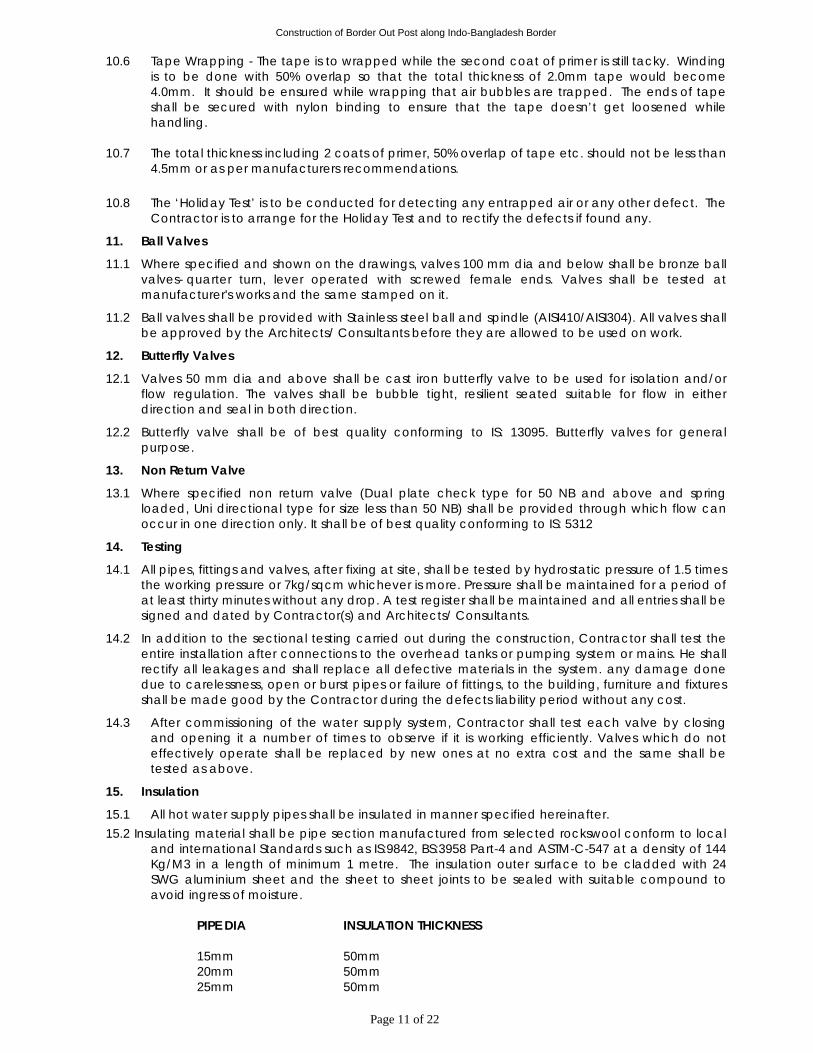
Construction of Border Out Post along Indo-Bangladesh Border
Page 11 of 22
10.6 Tape Wrapping - The tape is to wrapped while the second coat of primer is still tacky. Winding is to be done with 50% overlap so that the total thickness of 2.0mm tape would become 4.0mm. It should be ensured while wrapping that air bubbles are trapped. The ends of tape shall be secured with nylon binding to ensure that the tape doesn’t get loosened while handling.
10.7 The total thickness including 2 coats of primer, 50% overlap of tape etc. should not be less than
4.5mm or as per manufacturers recommendations. 10.8 The ‘Holiday Test’ is to be conducted for detecting any entrapped air or any other defect. The
Contractor is to arrange for the Holiday Test and to rectify the defects if found any.
11. Ball Valves
11.1 Where specified and shown on the drawings, valves 100 mm dia and below shall be bronze ball valves- quarter turn, lever operated with screwed female ends. Valves shall be tested at manufacturer's works and the same stamped on it.
11.2 Ball valves shall be provided with Stainless steel ball and spindle (AISI410/AISI304). All valves shall be approved by the Architects/ Consultants before they are allowed to be used on work.
12. Butterfly Valves
12.1 Valves 50 mm dia and above shall be cast iron butterfly valve to be used for isolation and/or flow regulation. The valves shall be bubble tight, resilient seated suitable for flow in either direction and seal in both direction.
12.2 Butterfly valve shall be of best quality conforming to IS: 13095. Butterfly valves for general purpose.
13. Non Return Valve
13.1 Where specified non return valve (Dual plate check type for 50 NB and above and spring loaded, Uni directional type for size less than 50 NB) shall be provided through which flow can occur in one direction only. It shall be of best quality conforming to IS: 5312
14. Testing
14.1 All pipes, fittings and valves, after fixing at site, shall be tested by hydrostatic pressure of 1.5 times the working pressure or 7kg/sqcm whichever is more. Pressure shall be maintained for a period of at least thirty minutes without any drop. A test register shall be maintained and all entries shall be signed and dated by Contractor(s) and Architects/ Consultants.
14.2 In addition to the sectional testing carried out during the construction, Contractor shall test the entire installation after connections to the overhead tanks or pumping system or mains. He shall rectify all leakages and shall replace all defective materials in the system. any damage done due to carelessness, open or burst pipes or failure of fittings, to the building, furniture and fixtures shall be made good by the Contractor during the defects liability period without any cost.
14.3 After commissioning of the water supply system, Contractor shall test each valve by closing and opening it a number of times to observe if it is working efficiently. Valves which do not effectively operate shall be replaced by new ones at no extra cost and the same shall be tested as above.
15. Insulation
15.1 All hot water supply pipes shall be insulated in manner specified hereinafter. 15.2 Insulating material shall be pipe section manufactured from selected rockswool conform to local
and international Standards such as IS:9842, BS:3958 Part-4 and ASTM-C-547 at a density of 144 Kg/M3 in a length of minimum 1 metre. The insulation outer surface to be cladded with 24 SWG aluminium sheet and the sheet to sheet joints to be sealed with suitable compound to avoid ingress of moisture.
PIPE DIA INSULATION THICKNESS
15mm 50mm 20mm 50mm 25mm 50mm
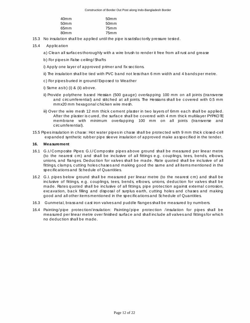
Construction of Border Out Post along Indo-Bangladesh Border
Page 12 of 22
40mm 50mm 50mm 50mm 65mm 75mm 80mm 75mm
15.3 No insulation shall be applied until the pipe is satisfactorily pressure tested.
15.4 Application
a) Clean all surfaces thoroughly with a wire brush to render it free from all rust and grease
b) For pipes in False ceiling/Shafts
i) Apply one layer of approved primer and fix sections.
ii) The insulation shall be tied with PVC band not less than 6 mm width and 4 bands per metre.
c) For pipes buried in ground/Exposed to Weather
i) Same as b) (i) & (ii) above.
ii) Provide polythene based Hessian (500 gauge) overlapping 100 mm on all joints (transverse and circumferential) and stitched at all joints. The Hessians shall be covered with 0.5 mm mmx20 mm hexagonal chicken wire mesh.
iii) Over the wire mesh 12 mm thick cement plaster in two layers of 6mm each shall be applied. After the plaster is cured, the surface shall be covered with 4 mm thick multilayer PYPKOTE membrane with minimum overlapping 100 mm on all joints (transverse and circumferential).
15.5 Pipes insulation in chase: Hot water pipes in chase shall be protected with 9 mm thick closed-cell expanded synthetic rubber pipe sleeve insulation of approved make as specified in the tender.
16. Measurement
16.1 G.I./Composite Pipes: G.I./Composite pipes above ground shall be measured per linear metre (to the nearest cm) and shall be inclusive of all fittings e.g. couplings, tees, bends, elbows, unions, and flanges. Deduction for valves shall be made. Rate quoted shall be inclusive of all fittings, clamps, cutting holes chases and making good the same and all items mentioned in the specifications and Schedule of Quantities.
16.2 G.I. pipes below ground shall be measured per linear metre (to the nearest cm) and shall be inclusive of fittings, e.g. couplings, tees, bends, elbows, unions, deduction for valves shall be made. Rates quoted shall be inclusive of all fittings, pipe protection against external corrosion, excavation, back filling and disposal of surplus earth, cutting holes and chases and making good and all other items mentioned in the specifications and Schedule of Quantities.
16.3 Gunmetal, brass and cast iron valves and puddle flanges shall be measured by numbers.
16.4 Painting/pipe protection/insulation: Painting/pipe protection /insulation for pipes shall be measured per linear metre over finished surface and shall include all valves and fittings for which no deduction shall be made.
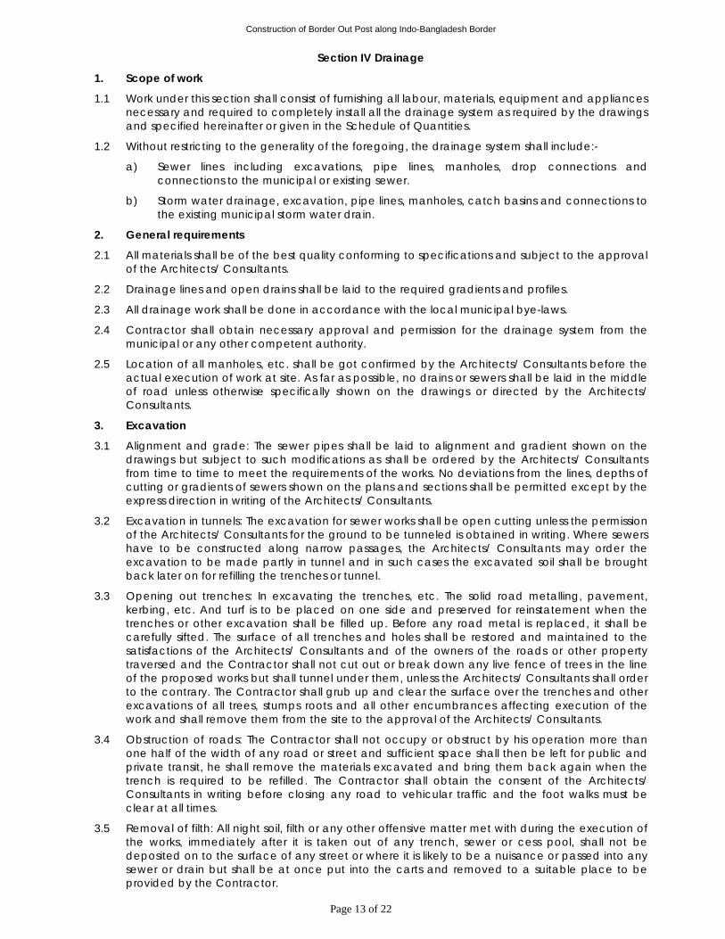
Construction of Border Out Post along Indo-Bangladesh Border
Page 13 of 22
Section IV Drainage
1. Scope of work
1.1 Work under this section shall consist of furnishing all labour, materials, equipment and appliances necessary and required to completely install all the drainage system as required by the drawings and specified hereinafter or given in the Schedule of Quantities.
1.2 Without restricting to the generality of the foregoing, the drainage system shall include:-
a) Sewer lines including excavations, pipe lines, manholes, drop connections and connections to the municipal or existing sewer.
b) Storm water drainage, excavation, pipe lines, manholes, catch basins and connections to the existing municipal storm water drain.
2. General requirements
2.1 All materials shall be of the best quality conforming to specifications and subject to the approval of the Architects/ Consultants.
2.2 Drainage lines and open drains shall be laid to the required gradients and profiles.
2.3 All drainage work shall be done in accordance with the local municipal bye-laws.
2.4 Contractor shall obtain necessary approval and permission for the drainage system from the municipal or any other competent authority.
2.5 Location of all manholes, etc. shall be got confirmed by the Architects/ Consultants before the actual execution of work at site. As far as possible, no drains or sewers shall be laid in the middle of road unless otherwise specifically shown on the drawings or directed by the Architects/ Consultants.
3. Excavation
3.1 Alignment and grade: The sewer pipes shall be laid to alignment and gradient shown on the drawings but subject to such modifications as shall be ordered by the Architects/ Consultants from time to time to meet the requirements of the works. No deviations from the lines, depths of cutting or gradients of sewers shown on the plans and sections shall be permitted except by the express direction in writing of the Architects/ Consultants.
3.2 Excavation in tunnels: The excavation for sewer works shall be open cutting unless the permission of the Architects/ Consultants for the ground to be tunneled is obtained in writing. Where sewers have to be constructed along narrow passages, the Architects/ Consultants may order the excavation to be made partly in tunnel and in such cases the excavated soil shall be brought back later on for refilling the trenches or tunnel.
3.3 Opening out trenches: In excavating the trenches, etc. The solid road metalling, pavement, kerbing, etc. And turf is to be placed on one side and preserved for reinstatement when the trenches or other excavation shall be filled up. Before any road metal is replaced, it shall be carefully sifted. The surface of all trenches and holes shall be restored and maintained to the satisfactions of the Architects/ Consultants and of the owners of the roads or other property traversed and the Contractor shall not cut out or break down any live fence of trees in the line of the proposed works but shall tunnel under them, unless the Architects/ Consultants shall order to the contrary. The Contractor shall grub up and clear the surface over the trenches and other excavations of all trees, stumps roots and all other encumbrances affecting execution of the work and shall remove them from the site to the approval of the Architects/ Consultants.
3.4 Obstruction of roads: The Contractor shall not occupy or obstruct by his operation more than one half of the width of any road or street and sufficient space shall then be left for public and private transit, he shall remove the materials excavated and bring them back again when the trench is required to be refilled. The Contractor shall obtain the consent of the Architects/ Consultants in writing before closing any road to vehicular traffic and the foot walks must be clear at all times.
3.5 Removal of filth: All night soil, filth or any other offensive matter met with during the execution of the works, immediately after it is taken out of any trench, sewer or cess pool, shall not be deposited on to the surface of any street or where it is likely to be a nuisance or passed into any sewer or drain but shall be at once put into the carts and removed to a suitable place to be provided by the Contractor.
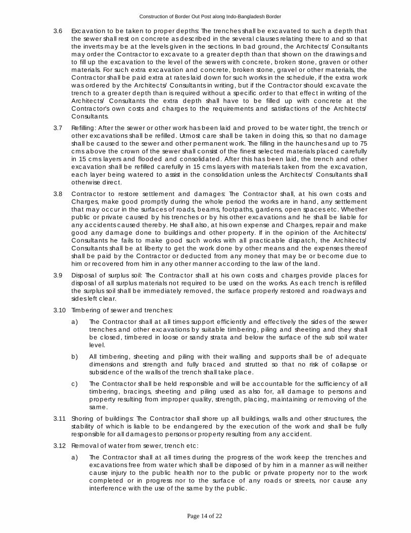
Construction of Border Out Post along Indo-Bangladesh Border
Page 14 of 22
3.6 Excavation to be taken to proper depths: The trenches shall be excavated to such a depth that the sewer shall rest on concrete as described in the several clauses relating there to and so that the inverts may be at the levels given in the sections. In bad ground, the Architects/ Consultants may order the Contractor to excavate to a greater depth than that shown on the drawings and to fill up the excavation to the level of the sewers with concrete, broken stone, graven or other materials. For such extra excavation and concrete, broken stone, gravel or other materials, the Contractor shall be paid extra at rates laid down for such works in the schedule, if the extra work was ordered by the Architects/ Consultants in writing, but if the Contractor should excavate the trench to a greater depth than is required without a specific order to that effect in writing of the Architects/ Consultants the extra depth shall have to be filled up with concrete at the Contractor's own costs and charges to the requirements and satisfactions of the Architects/ Consultants.
3.7 Refilling: After the sewer or other work has been laid and proved to be water tight, the trench or other excavations shall be refilled. Utmost care shall be taken in doing this, so that no damage shall be caused to the sewer and other permanent work. The filling in the haunches and up to 75 cms above the crown of the sewer shall consist of the finest selected materials placed carefully in 15 cms layers and flooded and consolidated. After this has been laid, the trench and other excavation shall be refilled carefully in 15 cms layers with materials taken from the excavation, each layer being watered to assist in the consolidation unless the Architects/ Consultants shall otherwise direct.
3.8 Contractor to restore settlement and damages: The Contractor shall, at his own costs and Charges, make good promptly during the whole period the works are in hand, any settlement that may occur in the surfaces of roads, beams, footpaths, gardens, open spaces etc. Whether public or private caused by his trenches or by his other excavations and he shall be liable for any accidents caused thereby. He shall also, at his own expense and Charges, repair and make good any damage done to buildings and other property. If in the opinion of the Architects/ Consultants he fails to make good such works with all practicable dispatch, the Architects/ Consultants shall be at liberty to get the work done by other means and the expenses thereof shall be paid by the Contractor or deducted from any money that may be or become due to him or recovered from him in any other manner according to the law of the land.
3.9 Disposal of surplus soil: The Contractor shall at his own costs and charges provide places for disposal of all surplus materials not required to be used on the works. As each trench is refilled the surplus soil shall be immediately removed, the surface properly restored and roadways and sides left clear.
3.10 Timbering of sewer and trenches:
a) The Contractor shall at all times support efficiently and effectively the sides of the sewer trenches and other excavations by suitable timbering, piling and sheeting and they shall be closed, timbered in loose or sandy strata and below the surface of the sub soil water level.
b) All timbering, sheeting and piling with their walling and supports shall be of adequate dimensions and strength and fully braced and strutted so that no risk of collapse or subsidence of the walls of the trench shall take place.
c) The Contractor shall be held responsible and will be accountable for the sufficiency of all timbering, bracings, sheeting and piling used as also for, all damage to persons and property resulting from improper quality, strength, placing, maintaining or removing of the same.
3.11 Shoring of buildings: The Contractor shall shore up all buildings, walls and other structures, the stability of which is liable to be endangered by the execution of the work and shall be fully responsible for all damages to persons or property resulting from any accident.
3.12 Removal of water from sewer, trench etc:
a) The Contractor shall at all times during the progress of the work keep the trenches and excavations free from water which shall be disposed of by him in a manner as will neither cause injury to the public health nor to the public or private property nor to the work completed or in progress nor to the surface of any roads or streets, nor cause any interference with the use of the same by the public.
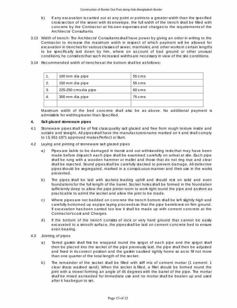
Construction of Border Out Post along Indo-Bangladesh Border
Page 15 of 22
b) If any excavation is carried out at any point or points to a greater width than the specified cross section of the sewer with its envelope, the full width of the trench shall be filled with concrete by the Contractor at his own expenses and charges to the requirements of the Architects/ Consultants.
3.13 Width of trench: The Architects/ Consultants shall have power by giving an order in writing to the Contractor to increase the maximum width in respect of which payment will be allowed for excavation in trenches for various classes of sewer, manholes, and other works in certain lengths to be specifically laid down by him, where on account of bad ground or other unusual conditions, he considers that such increased widths are necessary in view of the site conditions.
3.14 Recommended width of trenches at the bottom shall be as follows:-
1. 100 mm dia pipe 55 cms
2. 150 mm dia pipe 55 cms
3. 225-250 cms dia pipe 60 cms
4. 300 mm dia pipe 75 cms
Maximum width of the bed concrete shall also be as above. No additional payment is admissible for widths greater than Specified.
4. Salt glazed stoneware pipes
4.1 Stoneware pipes shall be of first class quality salt glazed and free from rough texture inside and outside and straight. All pipes shall have the manufacturers name marked on it and shall comply to I.S. 651-1971 approved makes Perfect or Burn.
4.2 Laying and jointing of stoneware salt glazed pipes
a) Pipes are liable to be damaged in transit and out withstanding tests that may have been made before dispatch each pipe shall be examined carefully on arrival at site. Each pipe shall be rung with a wooden hammer or mallet and those that do not ring true and clear shall be rejected. Sound pipes shall be carefully stacked to prevent damage. All defective pipes should be segregated, marked in a conspicuous manner and their use in the works prevented.
b) The pipes shall be laid with sockets leading uphill and should rest on solid and even foundations for the full length of the barrel. Socket holes shall be formed in the foundation sufficiently deep to allow the pipe jointer room to work right round the pipe and as short as practicable to admit the socket and allow the joint to be made.
c) Where pipes are not bedded on concrete the trench bottom shall be left slightly high and carefully bottomed up as pipe laying proceeds so that the pipe barrels rest on firm ground. If excavation has been carried too low it shall be made up with cement concrete at the Contractor's cost and Charges.
d) If the bottom of the trench consists of rock or very hard ground that cannot be easily excavated to a smooth surface, the pipes shall be laid on cement concrete bed to ensure even bearing.
4.3 Jointing of pipes
a) Tarred gaskin shall first be wrapped round the spigot of each pipe and the spigot shall then be placed into the socket of the pipe previously laid, the pipe shall then be adjusted and fixed in its correct position and the gaskin caulked tightly home so as to fill not more than one quarter of the total length of the socket.
b) The remainder of the socket shall be filled with stiff mix of cement mortar (1 cement: 1 clear sharp washed sand). When the socket is filled, a fillet should be formed round the joint with a trowel forming an angle of 45 degrees with the barrel of the pipe. The mortar shall be mixed as needed for immediate use and no mortar shall be beaten up and used after it has begun to set.
Construction of Border Out Post along Indo-Bangladesh Border
Page 16 of 22
c) After the joint has been made any extraneous materials shall be removed from inside of the joint with a suitable scraper of "badger". The newly made joints shall be protected until set from the sun, drying winds, rain or dust. Sacking or other materials which can be kept damp shall be used. The joints shall be exposed and space left all round the pipes for inspection by the Architects/ Consultants. The inside of the sewer must be left absolutely clear in bore and free from cement mortar or other obstructions throughout its entire length, and shall efficiently drain and discharge.
4.4 Testing
a) All lengths of the sewer and drain shall be fully tested for water tightness by means of water pressure maintained for not less than 30 minutes. Testing shall be carried out from manhole to manhole. All pipes shall be subjected to a test pressure of at least 1.5 metre head of water. The test pressure shall, however, not exceed 6 meter head at any point. The pipes shall be plugged preferably with standard design plugs with rubber plugs on both ends. The upper end shall, however, be connected to a pipe for filling with water and getting the required head.
b) Sewer lines shall be tested for straightness by:
(i) inserting a smooth ball 12 mm less than the internal diameter of the pipe. In the absence of obstructions such as yarn or mortar projecting at the joints the ball should roll down the invert of the pipe and emerge at the lower end,
(ii) means of a mirror at one and a lamp at the other end. If the pipe line is straight the full circle of light will be seen otherwise obstruction of deviation will be apparent.
c) The Contractor shall give a smoke test to the drains and sewer at his own expense and charges, if directed by the Architects/ Consultants.
d) A test register shall be maintained which shall be signed and dated by Contractor, Architects/ Consultants and representative of Architects/Consultants.
4.5 Gully traps: Gully traps shall be of the same quality as described for stoneware pipes in clause 5. Gully traps shall be fixed in cement concrete 1:5:10 mix and a brick masonry chamber 30x30 cms inside in cement mortar 1:5 with 15x15 cms grating inside and 30x30 cms SFRC cover as per standard drawing. Where necessary, sealed cover shall be replaced with C.I. grating of the same size (1 cement : 5 coarse sand: 10 stone aggregate 40 mm nominal size).
5. Reinforced cement concrete pipes
5.1 All underground storm water drainage pipes and sewer lines where specified (other than those specified cast iron) shall be centrifugally spun RCC pipes of specified class. Pipes shall be true and straight with uniform bore, throughout. Cracked, warped pipes shall not be used on the work. All pipes shall be tested by the manufacturer and the Contractor shall produce, when directed a certificate to that effect from the manufacturer.
5.2 Laying: R.C.C. spun pipes shall be laid on cement concrete bed or cradles as specified and shown on the detailed drawings. The cradles may be precast and sufficiently cured to prevent cracks and breakage in handling. The invert of the cradles shall be left 12 mm below the invert level of the pipe properly placed on the soil to prevent any disturbance. The pipe shall then be placed on the bed concrete or cradles and set for the line and gradient by means of sight rails and bonding rods etc. Cradles or concrete bed may be omitted, if directed by the Architects/ Consultants.
5.3 Jointing: After setting out the pipes the collar shall be centered over the joint and filled in with tarred gaskin, so that sufficient space is left on either side of the collar to receive the mortar. The space shall then be filled with cement mortar 1:2 (1 cement: 2 fine sand) and caulked by means of proper tools. All joints shall be finished at an angle of 45 degrees to the longitudinal axis of the pipe on both sides of the collars neatly.
5.4 Testing: All pipes shall be tested to a hydraulic test of 1.5 m head for at least 30 minutes at the highest point in the section under test. Test shall also be carried out similar to those for stoneware pipes given above .the smoke test shall be carried out by the Contractor, if directed by the Architects/ Consultants, at the expense and charges of the Contractor. A test register shall be maintained which shall be signed and dated by Contractor,/Architects/ Consultants and representative of Architects/Consultant.
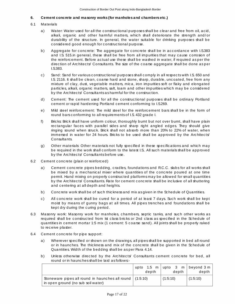
Construction of Border Out Post along Indo-Bangladesh Border
Page 17 of 22
6. Cement concrete and masonry works (for manholes and chambers etc.)
6.1 Materials
a) Water: Water used for all the constructional purposes shall be clear and free from oil, acid, alkali, organic and other harmful matters, which shall deteriorate the strength and/or durability of the structure. In general, the water suitable for drinking purposes shall be considered good enough for constructional purpose.
b) Aggregate for concrete: The aggregate for concrete shall be in accordance with I.S.383 and I.S. 515.in general, these shall be free from all impurities that may cause corrosion of the reinforcement. Before actual use these shall be washed in water, if required as per the direction of Architects/ Consultants. The size of the coarse aggregate shall be done as per I.S.383.
c) Sand: Sand for various constructional purposes shall comply in all respects with I.S. 650 and I.S. 2116. It shall be clean, coarse hard and stone, sharp, durable, uncoated, free from any mixture of clay, dust, vegetable matters, mica, iron impurities soft or flaky and elongated particles, alkali, organic matters, salt, loam and other impurities which may be considered by the Architects/ Consultants as harmful for the construction.
d) Cement: The cement used for all the constructional purposes shall be ordinary Portland cement or rapid hardening Portland cement conforming to I.S.269.
e) Mild steel reinforcement: The mild steel for the reinforcement bars shall be in the form of round bars conforming to all requirements of I.S. 432 grade I.
f) Bricks: Brick shall have uniform colour, thoroughly burnt but not over burnt, shall have plain rectangular faces with parallel sides and sharp right angled edges. They should give ringing sound when struck. Brick shall not absorb more than 20% to 22% of water, when immersed in water for 24 hours. Bricks to be used shall be approved by the Architects/ Consultants.
g) Other materials: Other materials not fully specified in these specifications and which may be required in the work shall conform to the latest I.S.. All such materials shall be approved by the Architects/ Consultants before use.
6.2 Cement concrete (plain or reinforced)
a) Cement concrete pipes bedding, cradles, foundations and R.C.C. slabs for all works shall be mixed by a mechanical mixer where quantities of the concrete poured at one time permit. Hand mixing on properly constructed platforms may be allowed for small quantities by the Architects/ Consultants. Rate for cement concrete shall be inclusive of all shuttering and centering at all depth and heights.
b) Concrete work shall be of such thickness and mix as given in the Schedule of Quantities.
c) All concrete work shall be cured for a period of at least 7 days. Such work shall be kept moist by means of gunny bags at all times. All pipes trenches and foundations shall be kept dry during the curing period.
6.3 Masonry work: Masonry work for manholes, chambers, septic tanks, and such other works as required shall be constructed from Ist class bricks or 2nd class as specified in the Schedule of quantities in cement mortar 1:5 mix (1 cement: 5 coarse sand). All joints shall be properly raked to receive plaster.
6.4 Cement concrete for pipe support:
a) Wherever specified or shown on the drawings, all pipes shall be supported in bed all round or in haunches. The thickness and mix of the concrete shall be given in the Schedule of Quantities. Width of the bedding shall be as per Para 4.14.
b) Unless otherwise directed by the Architects/ Consultants cement concrete for bed, all round or in haunches shall be laid as follows:-
upto 1.5 m depth
upto 3 m depth
beyond 3 m depth
Stoneware pipes all round in haunches all round in open ground (no sub soil water)
(1:5:10) (1:5:10) (1:5:10)
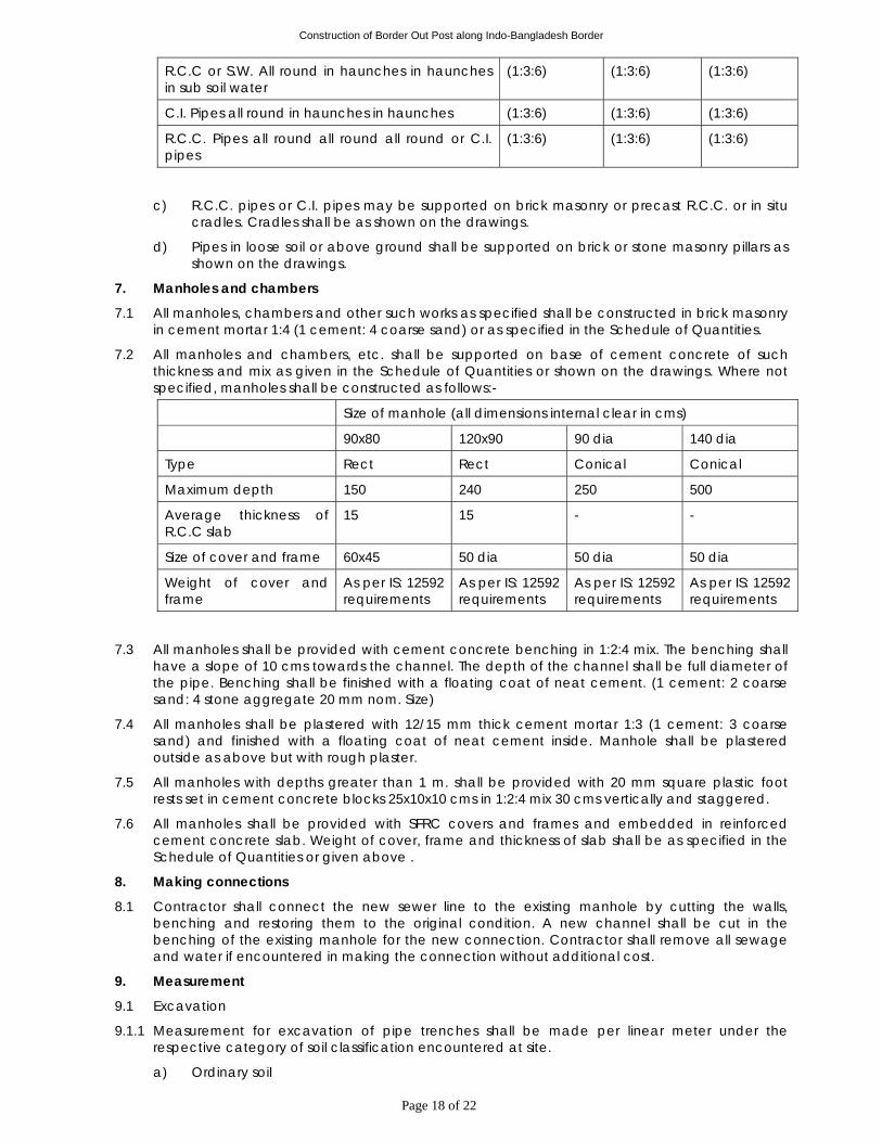
Construction of Border Out Post along Indo-Bangladesh Border
Page 18 of 22
R.C.C or S.W. All round in haunches in haunches in sub soil water
(1:3:6) (1:3:6) (1:3:6)
C.I. Pipes all round in haunches in haunches (1:3:6) (1:3:6) (1:3:6)
R.C.C. Pipes all round all round all round or C.I. pipes
(1:3:6) (1:3:6) (1:3:6)
c) R.C.C. pipes or C.I. pipes may be supported on brick masonry or precast R.C.C. or in situ cradles. Cradles shall be as shown on the drawings.
d) Pipes in loose soil or above ground shall be supported on brick or stone masonry pillars as shown on the drawings.
7. Manholes and chambers
7.1 All manholes, chambers and other such works as specified shall be constructed in brick masonry in cement mortar 1:4 (1 cement: 4 coarse sand) or as specified in the Schedule of Quantities.
7.2 All manholes and chambers, etc. shall be supported on base of cement concrete of such thickness and mix as given in the Schedule of Quantities or shown on the drawings. Where not specified, manholes shall be constructed as follows:-
Size of manhole (all dimensions internal clear in cms)
90x80 120x90 90 dia 140 dia
Type Rect Rect Conical Conical
Maximum depth 150 240 250 500
Average thickness of R.C.C slab
15 15 - -
Size of cover and frame 60x45 50 dia 50 dia 50 dia
Weight of cover and frame
As per IS: 12592 requirements
As per IS: 12592 requirements
As per IS: 12592 requirements
As per IS: 12592 requirements
7.3 All manholes shall be provided with cement concrete benching in 1:2:4 mix. The benching shall have a slope of 10 cms towards the channel. The depth of the channel shall be full diameter of the pipe. Benching shall be finished with a floating coat of neat cement. (1 cement: 2 coarse sand: 4 stone aggregate 20 mm nom. Size)
7.4 All manholes shall be plastered with 12/15 mm thick cement mortar 1:3 (1 cement: 3 coarse sand) and finished with a floating coat of neat cement inside. Manhole shall be plastered outside as above but with rough plaster.
7.5 All manholes with depths greater than 1 m. shall be provided with 20 mm square plastic foot rests set in cement concrete blocks 25x10x10 cms in 1:2:4 mix 30 cms vertically and staggered.
7.6 All manholes shall be provided with SFRC covers and frames and embedded in reinforced cement concrete slab. Weight of cover, frame and thickness of slab shall be as specified in the Schedule of Quantities or given above .
8. Making connections
8.1 Contractor shall connect the new sewer line to the existing manhole by cutting the walls, benching and restoring them to the original condition. A new channel shall be cut in the benching of the existing manhole for the new connection. Contractor shall remove all sewage and water if encountered in making the connection without additional cost.
9. Measurement
9.1 Excavation
9.1.1 Measurement for excavation of pipe trenches shall be made per linear meter under the respective category of soil classification encountered at site.
a) Ordinary soil
Construction of Border Out Post along Indo-Bangladesh Border
Page 19 of 22
b) Hard soil (hard moor & soft rock)
c) Hard rock requiring chiseling
d) Hard rock requiring blasting.
9.1.2 Trenches shall be measured between outside walls of manholes at top and the depth shall be the average depth between the two ends to the nearest cm. The rate quoted shall be for a depth up to 1.5 m or as given in the Schedule of Quantities.
9.1.3 Payment for trenches more than 1.5 m in depth shall be made for extra depth as given in the schedule of quantities and above the rate for depth up to 1.5 m.
9.1.4 Timbering and Shoring: Timbering and shoring as described above shall be measured per sq.m and paid for as per the type of timbering of shoring done at site and as per the relevant item in the Schedule of Quantities. Rate for timbering and shoring shall be for all depths and types of soil classifications including saturated soil.
9.1.5 Saturated Soil: No extra payment for pumping and bailing out water shall be made for excavation with an average depth of 1.5 m in saturated soil, surface water from rain falls or broken pipes lines, or sieves and other similar sources. An extra rate as quoted in the schedule of quantities shall be paid for excavation in saturated soil for pipe trenches above average depth of 1.5 m. No payment is admissible for water collected from surface sources and broken pipe lines or sewers.
9.1.6 Refilling, Consolidation and Disposal of Surplus Earth: Rate quoted for excavation of trenches shall be inclusive of refilling, consolidation and disposal of surplus earth within a lead of 200 m.
9.2 Stoneware Pipes/RCC/C.I. pipes: Stoneware R.C.C./C.I. pipes shall be measured for the finished length of the pipeline per linear metre ie.
(a) Lengths between manholes shall be recorded from inside of one manhole to inside of other manhole,
(b) Length between gully trap and manhole shall be recorded between socket of pipe near gully trap and inside of manhole. Rate shall include all items given in the schedule of quantities and specifications.
9.3 Gully Traps: Gully traps shall be measured by the number and rate shall include all excavation, foundation, concrete brick masonry, cement plaster inside and outside, C.I. grating and sealed cover and frame.
9.4 Cement Concrete for Pipes: Cement concrete in bed and all round or in haunches shall be paid per running metre between the outside wall of manholes at bottom of the trench. No additional payment is admissible in respect of concreting done for widths greater than specified, for shuttering or centering and concreting in sub soil water conditions.
9.5 Manholes:
a) All manholes shall be measured by numbers and shall include all items specified above and necessary excavation, refilling & disposal of surplus earth.
b) Manholes with depths greater than specified under the main item shall be paid for under "extra depth" and shall include all items as given for manholes. measurement shall be done to the nearest cm. Depth of the manholes shall be measured from top of the manhole cover to bottom of channel.
9.6 Making Connections: Item for making connection to municipal sewer shall be paid for by number and shall include all items given in the Schedule of Quantities and specifications.
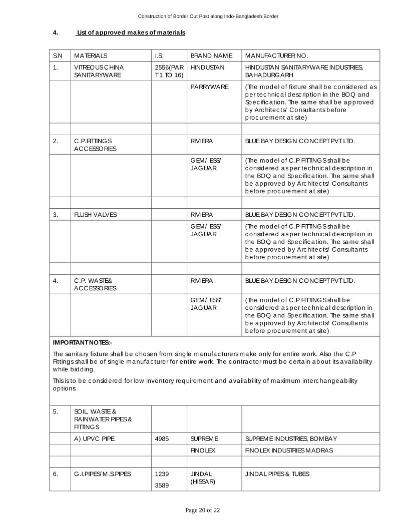
Construction of Border Out Post along Indo-Bangladesh Border
Page 20 of 22
4. List of approved makes of materials
S.N MATERIALS I.S. BRAND NAME MANUFACTURER NO.
1. VITREOUS CHINA SANITARYWARE
2556(PART 1 TO 16)
HINDUSTAN HINDUSTAN SANITARYWARE INDUSTRIES, BAHADURGARH
PARRYWARE (The model of fixture shall be considered as per technical description in the BOQ and Specification. The same shall be approved by Architects/ Consultants before procurement at site)
2. C.P.FITTINGS ACCESSORIES
RIVIERA BLUE BAY DESIGN CONCEPT PVT LTD.
GEM/ ESS/ JAGUAR
(The model of C.P FITTINGS shall be considered as per technical description in the BOQ and Specification. The same shall be approved by Architects/ Consultants before procurement at site)
3. FLUSH VALVES RIVIERA BLUE BAY DESIGN CONCEPT PVT LTD.
GEM/ ESS/ JAGUAR
(The model of C.P FITTINGS shall be considered as per technical description in the BOQ and Specification. The same shall be approved by Architects/ Consultants before procurement at site)
4. C.P. WASTE& ACCESSORIES
RIVIERA BLUE BAY DESIGN CONCEPT PVT LTD.
GEM/ ESS/ JAGUAR
(The model of C.P FITTINGS shall be considered as per technical description in the BOQ and Specification. The same shall be approved by Architects/ Consultants before procurement at site)
IMPORTANT NOTES:-
The sanitary fixture shall be chosen from single manufacturers make only for entire work. Also the C.P Fittings shall be of single manufacturer for entire work. The contractor must be certain about its availability while bidding.
This is to be considered for low inventory requirement and availability of maximum interchangeability options.
5. SOIL, WASTE & RAINWATER PIPES & FITTINGS
A) UPVC PIPE 4985 SUPREME SUPREME INDUSTRIES, BOMBAY
FINOLEX FINOLEX INDUSTRIES MADRAS
6. G.I.PIPES/M.S.PIPES 1239
3589
JINDAL (HISSAR)
JINDAL PIPES & TUBES
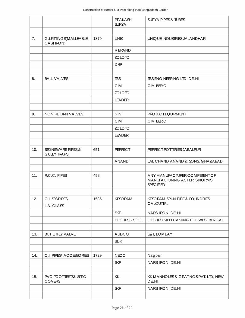
Construction of Border Out Post along Indo-Bangladesh Border
Page 21 of 22
PRAKASH SURYA
SURYA PIPES & TUBES
7. G.I.FITTINGS(MALLEABLE CAST IRON)
1879 UNIK UNIQUE INDUSTRIES JALANDHAR
R BRAND
ZOLOTO
DRP
8. BALL VALVES TBS TBS ENGINEERING LTD, DELHI
CIM CIM BERIO
ZOLOTO
LEADER
9. NON RETURN VALVES SKS PROJECT EQUIPMENT
CIM CIM BERIO
ZOLOTO
LEADER
10. STONEWARE PIPES & GULLY TRAPS
651 PERFECT PERFECT POTTERIES JABALPUR
ANAND LAL CHAND ANAND & SONS, GHAZIABAD
11. R.C.C. PIPES 458 ANY MANUFACTURER COMPETENT OF MANUFACTURING AS PER IS NORMS SPECIFIED
12. C.I. S/S PIPES,
L.A. CLASS
1536 KESORAM KESORAM SPUN PIPE & FOUNDRIES CALCUTTA.
SKF NARSI IRON, DELHI
ELECTRO- STEEL ELECTROSTEELCASTING LTD. WEST BENGAL
13. BUTTERFLY VALVE AUDCO L&T, BOMBAY
BDK
14. C.I. PIPES/ ACCESSORIES 1729 NECO Nagpur
SKF NARSI IRON, DELHI
15. PVC FOOTRESTS& SFRC COVERS
KK KK MANHOLES & GRATINGS PVT. LTD, NEW DELHI.
SKF NARSI IRON, DELHI
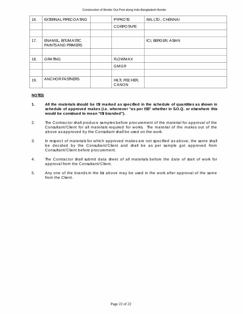
Construction of Border Out Post along Indo-Bangladesh Border
Page 22 of 22
16. EXTERNAL PIPECOATING PYPKOTE IWL LTD., CHENNAI
CORPOTAPE
17. ENAMEL, BITUMASTIC PAINTS AND PRIMERS
ICI, BERGER, ASIAN
18. GRATING FLOWMAX
GMGR
19. ANCHOR FASTNERS HILTI, FISCHER, CANON
NOTES: 1. All the materials should be ISI marked as specified in the schedule of quantities as shown in
schedule of approved makes (i.e. whenever “as per ISS” whether in S.O.Q. or elsewhere this would be construed to mean “ISI branded”).
2. The Contractor shall produce samples before procurement of the material for approval of the
Consultant/Client for all materials required for works. The material of the makes out of the above as approved by the Consultant shall be used on the work.
3. In respect of materials for which approved makes are not specified as above, the same shall
be decided by the Consultant/Client and shall be as per sample got approved from Consultant/Client before procurement.
4. The Contractor shall submit data sheet of all materials before the date of start of work for
approval from the Consultant/Client. 5. Any one of the brands in the list above may be used in the work after approval of the same
from the Client.
Construction of Border Out Post along Indo-Bangladesh Border
Page 1 of 21
TECHNICAL SPECIFICATIONS FOR FIRE FIGHTING AND WATER PUMPING SYSTEM
Section I - Specifications for Fire protection system PART-1 GENERAL SPECIFICATION 1. Scope of work
1.1 The form of Contract shall be according to the "Conditions of Contract". The following clauses shall be considered as an extension and not in limitation of the obligation of the Contractor.
1.2 Work under this Contract shall consist of furnishing all labour, materials, equipment and appliances necessary and required. The Contractor is required to completely furnish all the Fire fighting system and other specialized services as described hereinafter and as specified in the schedule of quantities and/or shown on the Fire fighting system drawings.
1.3 Without restricting to the generality of the foregoing, the Fire Fighting system installations shall include the following:-
i) Fire Pumps.
ii) Hydrant system installation
iii) Fire Fighting Piping installation
iv) Getting Approval of Fire system installation from local fire authority for Fire hydrant, Sprinkler and Fire Alarm system.
v) Co-ordination with other agencies during process of NOC for fire approval from Local fire authority.
1.4 Services rendered under this section shall be done without any extra charge.
2. Specifications
2.1 Work under this Contract shall be carried out strictly in accordance with specifications attached with the tender.
2.2 Items not covered under these specifications due to any ambiguity or misprints or additional works, the work shall be carried out as per latest specifications of the Central Public Works Department with upto date amendments as applicable in the Contract.
2.3 Works not covered under para 2.1 and 2.2 shall be carried out as per relevant Indian Standards specifications and Code of Practice as applicable (TAC, NFPA and NBC).
3. Execution of work
3.1 The Contractor should visit and examine the site of work and satisfy himself as to the nature of the existing roads and other means of communication and other details pertaining to the work and local conditions and facilities for obtaining his own information on all matters affecting the execution of work. No extra charge made in consequence of any misunderstanding or incorrect information on any of these points or on grounds of insufficient description will be allowed.
3.2 The work shall be carried out in conformity with the Fire fighting drawings and within the requirements of architectural, HVAC, electrical, structural and other specialized services drawings.
3.3 The Contractor shall cooperate with all trades and agencies working on the site.
3.4 On award of the work, Contractor shall submit a schedule of construction in the form of a pert chart or bar chart for approval of the Engineer-in-Charge. All dates and time schedule agreed upon shall be strictly adhered to, within the stipulated time of completion/commissioning along with the specified phasing, if any.
Construction of Border Out Post along Indo-Bangladesh Border
Page 2 of 21
4. Drawings
4.1 Fire fighting drawings are diagrammatic but shall be followed as closely as actual construction permits. Any deviations made shall be in conformity with the architectural and other services drawings.
4.2 Architectural drawings shall take precedence over fire fighting system or other services drawings as to all dimensions.
4.3 Contractor shall verify all dimensions at site and bring to the notice of the Engineer-in-Charge all discrepancies or deviations noticed. Decision of the Engineer-in-Charge shall be final.
4.4 Large size details and manufacturers dimensions for materials to be incorporated shall take precedence over small scale drawings.
4.5 Any drawings issued by the Architects/Consultant for the work are the property of the Architects/Consultant and shall not be lent, reproduced or used on any works other than intended without the written permission of the Architects/Consultant.
5. Inspection and testing of materials
5.1 Contractor shall be required, if requested, to produce manufacturers test certificate for the particular batch of materials supplied to him. The tests carried out shall be as per the relevant Indian Standards.
5.2 For examination and testing of materials and works at the site Contractor shall provide all testing and gauging equipment necessary and required at site for such tests.
5.3 All such equipment shall be tested for calibration at any approved laboratory, if required by the Engineer-in-Charge.
5.4 Samples of all materials shall be got approved before placing order and the approved samples shall be deposited with the Engineer-in-charge. Any materials declared defective by Engineer-in-Charge shall be removed from the site within 48 hours.
6. Metric conversion
6.1 All dimensions and sizes of materials and equipment given in the tender document are commercial metric sizes.
6.2 Any weights or sizes given in the tender having changed due to metric conversion, the nearest equivalent sizes accepted by Indian Standards shall be acceptable without any additional cost.
7. Reference points
7.1 Contractor shall provide permanent bench marks, flag tops and other reference points for the proper execution of work and these shall be preserved till the end of the work.
7.2 All such reference points shall be in relation to the levels and locations, given in the architectural and Fire fighting drawings.
8. Reference drawings
8.1 The Contractor shall maintain one set of all drawings issued to him as reference drawings. These shall not be used on site. All important drawings shall be mounted on boards indexed and placed in racks no drawings shall be rolled.
8.2 All corrections, deviations and changes made on the site shall be shown on these reference drawings for final incorporations in the completion drawings. All changes to be made shall be initialed by the Engineer-in-Charge.
9. Shop drawings
9.1 The Contractor shall submit to the Engineer-in-Charge four copies of the shop drawings.
9.2 Shop drawings shall be submitted under following conditions:-
a) Showing any changes in layout in the fire fighting system drawings.
b) Equipment layout, piping and wiring diagram.
c) Manufacturer's or Contractor's fabrication drawings for any materials or equipment supplied by him.
Construction of Border Out Post along Indo-Bangladesh Border
Page 3 of 21
9.3 The Contractor shall submit four copies of catalogues, manufacturer's drawings, equipment characteristics data or performance charts as required by the Engineer-in-Charge.
10. Completion drawings
10.1 On completion of work, Contractor shall submit one complete set of original tracings and two prints of "As Built" drawings to the Engineer-in-Charge. These drawings shall have the following information.
a) Run of all piping, diameters on all floors, vertical stacks and location of external services.
b) Ground and invert levels of all fire pipes together with location of all manholes and connections up to outfall.
c) Run of all fire pipe lines with diameters, locations of control valves, access panels.
d) Location of all mechanical equipment with layout and piping connections.
NOTE: No completion certificate shall be issued unless the above drawings are submitted.
10.2 Contractor shall provide four sets of catalogues, service manuals, manufacturer's drawings, performance data and list of spare parts together with the name and address of the manufacturer for all electrical and mechanical equipment provided by him.
10.3 All "Warranty Cards" given by the manufacturers shall be handed over to the Engineer-in-Charge.
11. Contractor's rates
Refer to relevant clause of General Conditions of contracts.
12. Testing
12.1 Piping and drainage works shall be tested as specified under the relevant clauses of the specifications.
12.2 Tests shall be performed in presence of the Engineer-in-Charge.
12.3 All materials and equipment found defective shall be replaced and whole work tested to meet the requirements of the specifications.
12.4 Contractor shall perform all such tests as may be necessary and required by the local authorities to meet municipal or other bye-laws in force.
12.5 Contractor shall provide all labour, equipment and materials for the performance of the tests.
13. Site clearance and cleanup
13.1 The Contractor shall, from time to time, clear away all debris and excess materials accumulated at the site.
13.2 After the fixtures, equipment and appliances have been installed and commissioned, Contractor shall clean-up the same and remove all plaster, paints, stains, stickers and other foreign matter or discoloration leaving the same in a ready to use condition.
13.3 On completion of all works, Contractor shall demolish all stores, remove all surplus materials and leave the site in a broom clean condition, failing which the same shall be done at Contractor's risk and cost.
14. License, permits and authorities
14.1 Contractor must hold a valid any other license as required by the municipal authority or other competent authority under whose jurisdiction the work falls.
14.2 Contractor must keep constant liaison with the municipal /statutory authority and obtain approval of all fire fighting system and other works carried out by him.
14.3 Contractor shall obtain, from the municipal and other authorities on completion of his work No Objection Certificate with respect to his work, as required for occupation of the building. Engineer-in-Charge shall reimburse the fees paid to the authorities towards the statutory fee charges on production of receipts for money paid.
Construction of Border Out Post along Indo-Bangladesh Border
Page 4 of 21
15. Recovery of cost for materials issued to Contractors free of cost
15.1 If any materials issued to the Contractor, free of cost, are damaged or pilfered, the cost of the same shall be recovered from the Contractor on the basis of actual cost to owner which shall include all freight and transportation, excise duty, sales tax, octroi, import duty etc, plus 100%. The decision on the actual cost given by the Engineer-in-Charge shall be final and binding on the Contractor.
16. Cutting of Water Proofing Membrane
16.1 No walls or terraces shall be cut for making any opening after water proofing has been done without written approval of Engineer-in-charge. When permitted cutting of water proofing membrane shall be done very carefully so that other portion of water proofing is not damaged. On completion of work at such place the water proofing membrane shall be made good and ensured that the opening/cutting is made fully water proof as per contract specifications and details of water proofing.
17. Cutting of structural members
17.1 No structural member shall be chased or cut without the written permission of the Engineer-in-Charge.
18. Materials supplied by Employer
18.1 The Contractor shall verify that all materials supplied by the Employer conform to the specifications of the relevant item in the tender and approved technical datasheet. Any discrepancy found shall be brought to the notice of the Engineer-in-Charge.
19. Materials
19.1 The contractor shall submit technical datasheets of all materials before procurement at site for approval by Consultant/ Engineer-in-Charge. No material will be inspected/ acceptable without duly approved technical datasheet by the consultants.
19.2 Unless otherwise specified and expressly approved in writing by the Engineer-in-Charge, only materials of makes and specification as mentioned in the list of approved makes attached with the specifications shall be used.
19.2 If required, the Contractor shall submit samples of materials proposed to be used in the works. Approved samples shall be kept in the office of the Engineer-in-Charge and returned to the Contractor at the appropriate time.
PART-2 SPECIFICATIONS FOR PUMPS AND ANCILLARY EQUIPMENT 1.0 SCOPE OF WORK 1.1 Work under this section shall consist of furnishing all labour, materials, equipment and
appliances necessary and required to completely install electrically operated pumps for fire hydrant installations as required by the drawings and specified hereinafter or given in the schedule of quantities.
1.2 Without restricting to the generality of the foregoing the pumps and the ancillary equipment and shall include the following :
a) Electrically operated pumps with motors, base plate and accessories. b) Pump suction and delivery headers, valves, air vessel and connections.
c) Pressure gauges/Pressure switch d) Electrical switch board, wiring, cabling, cable tray, control panel and properly connecting to
earthing system of the Factory. 2.0 GENERAL REQUIREMENTS 2.1 Pumps shall be installed true to level on suitable concrete foundations. Base plate shall be
firmly fixed by foundation bolts properly grouted in the concrete foundations. 2.2 Pumps and motors shall be truly aligned with suitable instruments. 2.3 All pump connections shall be standard flanged type with appropriate number of bolts. 2.4 Manufacturers instructions regarding installation connections and commissioning shall be
followed with respect to all pumps, switch gear and accessories.
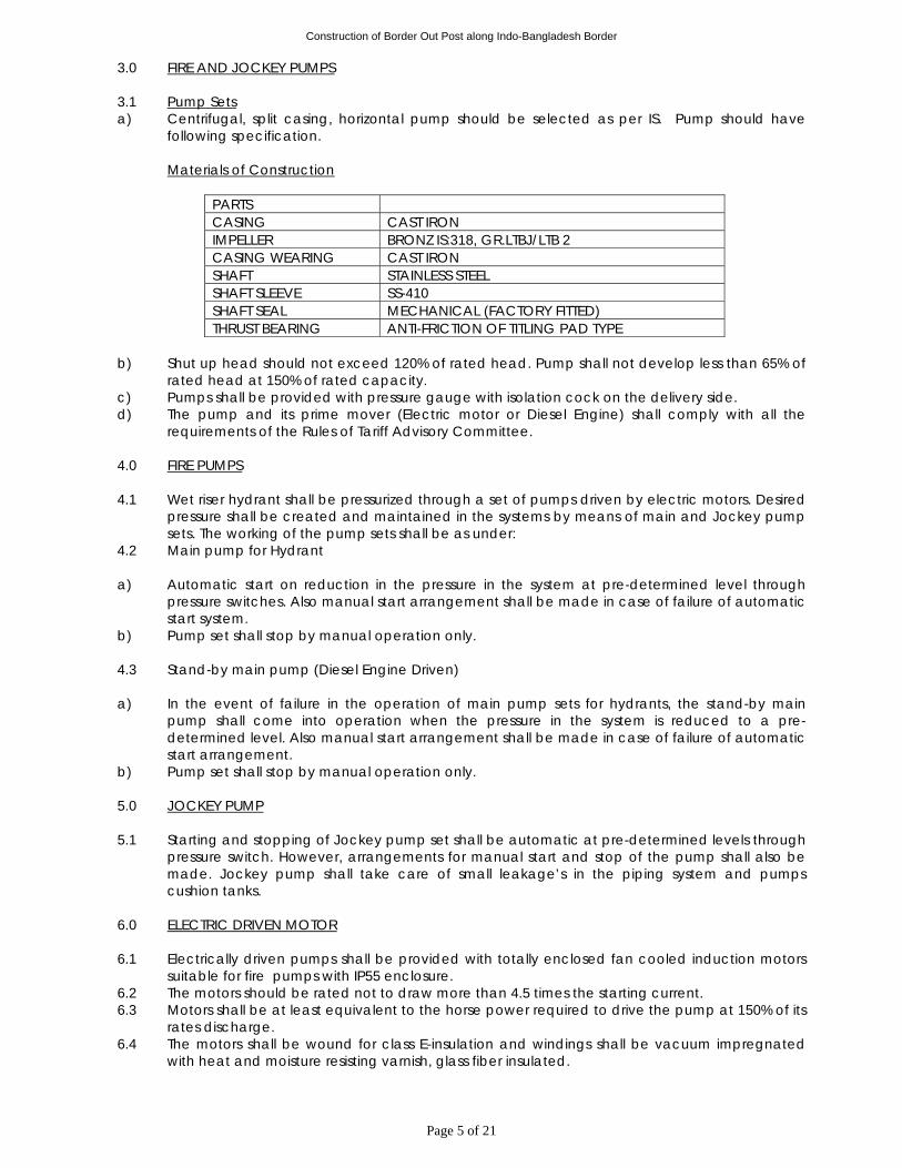
Construction of Border Out Post along Indo-Bangladesh Border
Page 5 of 21
3.0 FIRE AND JOCKEY PUMPS 3.1 Pump Sets a) Centrifugal, split casing, horizontal pump should be selected as per IS. Pump should have
following specification. Materials of Construction
PARTS CASING CAST IRON IMPELLER BRONZ IS:318, GR.LTBJ/LTB 2 CASING WEARING CAST IRON SHAFT STAINLESS STEEL SHAFT SLEEVE SS-410 SHAFT SEAL MECHANICAL (FACTORY FITTED) THRUST BEARING ANTI-FRICTION OF TITLING PAD TYPE
b) Shut up head should not exceed 120% of rated head. Pump shall not develop less than 65% of
rated head at 150% of rated capacity. c) Pumps shall be provided with pressure gauge with isolation cock on the delivery side. d) The pump and its prime mover (Electric motor or Diesel Engine) shall comply with all the
requirements of the Rules of Tariff Advisory Committee. 4.0 FIRE PUMPS 4.1 Wet riser hydrant shall be pressurized through a set of pumps driven by electric motors. Desired
pressure shall be created and maintained in the systems by means of main and Jockey pump sets. The working of the pump sets shall be as under:
4.2 Main pump for Hydrant a) Automatic start on reduction in the pressure in the system at pre-determined level through
pressure switches. Also manual start arrangement shall be made in case of failure of automatic start system.
b) Pump set shall stop by manual operation only. 4.3 Stand-by main pump (Diesel Engine Driven) a) In the event of failure in the operation of main pump sets for hydrants, the stand-by main
pump shall come into operation when the pressure in the system is reduced to a pre-determined level. Also manual start arrangement shall be made in case of failure of automatic start arrangement.
b) Pump set shall stop by manual operation only. 5.0 JOCKEY PUMP 5.1 Starting and stopping of Jockey pump set shall be automatic at pre-determined levels through
pressure switch. However, arrangements for manual start and stop of the pump shall also be made. Jockey pump shall take care of small leakage’s in the piping system and pumps cushion tanks.
6.0 ELECTRIC DRIVEN MOTOR 6.1 Electrically driven pumps shall be provided with totally enclosed fan cooled induction motors
suitable for fire pumps with IP55 enclosure. 6.2 The motors should be rated not to draw more than 4.5 times the starting current. 6.3 Motors shall be at least equivalent to the horse power required to drive the pump at 150% of its
rates discharge. 6.4 The motors shall be wound for class E-insulation and windings shall be vacuum impregnated
with heat and moisture resisting varnish, glass fiber insulated.
Construction of Border Out Post along Indo-Bangladesh Border
Page 6 of 21
7.0 DIESEL ENGINE 7.1 Diesel Engine shall be of 4/6 cylinders with individual heat assemblies. The engine shall be
water cooled and shall include heat exchanger and connecting piping strainer, isolating and pressure reducing valves, bye-pass line, exhaust pipe, silencer, day tank for fuel all interconnected piping etc. complete in all respects.
7.2 Engine shall be direct injection type with low noise and exhaust emission levels. 7.3 The speed of engine shall match the pump speed for direct drive. 7.4 The engine shall be capable of being started without the use of the wicks, cartridge heater
plugs or either at engine room temperature of 4 deg. C and shall take full load within 15 seconds from the receipt of the signal to start.
7.5 The engine shall effectively operate at 46 Deg.C ambient temperature at 150 meter above mean sea level.
7.6 Noise level of the engine shall not exceed 105 db. (free sound pressure) at 3 meters distance. 7.7 The engine shall be self starting type upto 4 deg.C shall be provided with one 24 volts heavy
duty D.C. battery, starter, cutout, battery leads complete in all respects. The battery shall have a capacity of 200 ampere hours and 640 amperes cold cranking amperage. Pump Control Panel should have visual and audio alarm and indication for battery failure. The battery should have output amperage capacity for at least 3 consecutive cranking/starting of the Engine.
7.8 Provide a battery charger of 20 amperage capacity of fully charge the batteries in 20 hours with tickle and booster charging facility and regulators.
7.9 Arrangement for starting shall be automatic on receiving the signal. But shut-off shall be manual.
7.10 The engine shall be provided with an oil bath or dry type air cleaner as per manufacturer’s design.
7.11 Engine shall be suitable for running on high speed diesel oil. 7.12 The system shall be provided with a control panel with push button starting arrangement also
wired to operate the engine on differential pressure gauge. 7.13 The entire system shall be mounted on a common structural base plate with anti vibration
mounting, Dunlop make, and flexible connections on the suction and delivery piping. 7.14 Contractor provide one fully mounted and supported day oil tank fabricated from 6mm thick
MS sheet electrically welded of 8 hours working load but not less than 200 ltrs. Provide level indicators - low level and full level in the day oil tank on the control panel through float switches and an air breather. Day oil tank shall also be provided with filling connection (threaded) with cap, gauge glass indication & cocks, drain cock, inspection/cleaning cover with gasket and nuts/bolts. M.S. dyke to hold 150% of the Day Tank capacity to be built around the Day Tank.
7.15 Contractor to provide one exhaust pipe with suitable muffler (residential type) to discharge the engine gasses to outside in open air as per site conditions (contractor to check the site).
7.16 Contractor to provide all accessories, fittings, and fixtures necessary and required for a complete operating engine set. The exhaust pipe shall be taken outside the building with minimum number of bends (approx. length 30 mts.) and shall be duly heat insulated with 50 mm thick glass wool covered with 24 gauge aluminium cladding.
7.17 Contractor shall indicate special requirements, if any, for the ventilation of the pump room. 8.0 BASE PLATE 8.1 Pumps and motors shall be mounted on a common structural base plate and installed as per
manufacturers instructions. 9.0 VIBRATION ELIMINATORS 9.1 The Contractor shall provide on all suction and delivery lines double flanged reinforced
neoprene flexible pipe connectors. Connectors should be suitable for a working pressure of each pump and tested to the test pressure given in the relevant head. Length of the test connector shall be as per manufacturer details.
Construction of Border Out Post along Indo-Bangladesh Border
Page 7 of 21
10.0 CUBICLE TYPE SWITCH BOARDS/L.T. PANEL 10.1 Cubicle type switch boards and components shall conform to the requirements of the latest
revision including amendments of the following codes and standards.
IS:8623 : Specification for factory built assemblies of switch- gear
and control gear for voltage up to and including 1000-V AC/1200 V-DC.
IS:4237 : General requirements for switch-gear and control-gear for voltage not exceeding 1000-V.
IS:2147 : Degree of protection provided by enclosures for low voltage switch-gear and control-gear.
IS:1018 : Switchgear and control-gear selection/installation and maintenance.
IS:6005 : Code of practice for phosphating of iron and steel.
IS:13947-1993/ IEC947-1989
: Air circuit breaker/Moulded case circuit breaker.
IS:1248 : Direct acting indicating analogue electrical measuring instruments and testing accessories.
IS:2705 Part I, II & III 1964
: Current transformers for metering & protection with classification burden & insulation.
The board shall be metal enclosed single front, indoor, floor mounted free standing type or wall mounting type as mentioned in BOQ. The panel shall be designed for a degree of protection of IP-52. The panel height shall not exceed 2350 mm including horizontal main bus bar at top. Keeping in view the operating height of the top switch 1750mm from finish floor. 400 mm clear space shall be left through out the panel at bottom. The cold rolled sheet steel will be of 2mm thick. All cut-outs and covers shall be provided with synthetic rubber gaskets. (Preferably neoprene).
The panel shall be divided into distinct vertical sections each comprising of:
i) Complete enclosed bus bar compartment for running horizontal and vertical bus bars. ii) Complete enclosed switch gear compartment one for each circuit for housing air
circuit breaker, MCCB etc. iii) Compartmentally for power and control cables of at least 300mm width covering
entire height provided. iv) All cable alley must be provided with threaded nipples for CO flooding system and
shall be connected to all compartment with centralized CO system v) The panel shall have 20% spare space duly wired for future use. The front of each compartment shall be provided with hinged single lead door with locking facilities. Panel shall be provided with suitable lifting facilities. Isolators & MCCB/ACBs shall be of fixed/draw out type as described later. Each feeder shall have compartmentalized construction cable entry shall be from top/bottom (3mm thick gland plate shall be provided) as required. The panel shall be provided with three phase buses and neutral bus bars of aluminum sections throughout the length of the panel and shall be adequately supported and braced to withstand the stresses due to the short circuit current of 50 KA rms. for 1 sec. Maximum temperature rise of bus bars and bus bar connection while carrying rated current shall not exceed 40 C over an ambient temperature of 50 C.
Construction of Border Out Post along Indo-Bangladesh Border
Page 8 of 21
The minimum clearance in air between phases and between phases and earth for the entire run of the bus bar connections shall be 25mm minimum bus bars support insulators shall be made of non-hydroscopic non-combustible track resistant and high strength type porcelain or polyester fibre glass moulded material. All bus bars shall be colour coded as per IS: 375. G.I. earth bus of 50x6mm size shall be provided at the bottom of the panel through out the length. Similarly 40x6mm G.I. strip in each vertical section for earthing the individual equipment/accessories shall be provided and connected to main horizontal bus. All fuses shall be of HRC cartridge plug in type and shall be of class 2 type (80 KA rms) breaking capacity. Fuses shall have visible operation indications. Neutral link shall be mounted on fuse carriers which shall be mounted on fuse bases. Contactors shall be electro-magnetic type with interrupted duty as per IS:2959. The main contacts shall be of Silver or silver alloy, provided with minimum 2 NO and 2 NC auxiliary contacts. The push button should be of shrouded type and each should be provided with 1 NO and 1 NC contact. Colour coding shall be as per IS:6875 (Part II).
10.2 ACB
The circuit breaker shall be of air break type in order to eliminate fire and explosion risk and shall comply with the IS:13947-1993 with a rupturing capacity of not less than 50 MVA at 415 volts or as specified elsewhere (The service short circuit breaking capacity shall be as specified and equal to the short circuit with stand value). The breaker shall be provided with microprocessor based releases for over load and short circuit protection. The breaker shall consist of a horizontal drawout pattern triple pole, fully interlocked, independent manual spring operated mechanism. The mechanism should be such that the circuit breaker is at all times free to open immediately. The trip coil is energised. Current carrying parts should be silver plated and suitable arcing contacts shall be provided to protect the main contact arc-chutes for each pole shall be provided and shall be lifted out for the inspection of main and arching contact. Self aligning cluster type isolating contacts shall be provided on breaker for interlocking protection metering and for any other purposes. Breaker shall be provided with automatic safety shutters to screen the main live contact when the breaker is withdrawn. The frame of the circuit breaker should be positively earthed when the breaker is racked into the cubicle. The following safety arrangements shall be provided for the safety of the personnel to prevent mal-operation. i) Interlock to prevent the truck from being withdrawn or replaced except in the fully
isolated position. ii) Interlock to prevent earth connection from being made by the earthing device except
breaker is open. iii) Interlock to prevent the breaker from being made alive without its rack in position.
10.3 Moulded Case Circuit Breaker (MCCB)
MCCB shall conform to the latest IS:13947-1993/IEC 947-1989. The Service Short Circuit Breaking Capacity (ICS at 415 VAC) should be 50 KA. MCCB shall be Current Limiting and comprise of Quick Make - Break switching mechanism preferably Double Break Contact system are extinguishing device and the tripping unit contained in a compact, high strength, heat resistant, flame retardent, insulating moulded case with high withstand capability against thermal and mechanical stresses. All MCCBs shall be capable of defined variable overload adjustment. All MCCBs rated 200 Amps and above shall have adjustable Magnetic short circuit pick up.
Construction of Border Out Post along Indo-Bangladesh Border
Page 9 of 21
The trip command shall over ride all other commands. MCCB shall employ maintenance free double break contact system to minimise the let thru’ energies and capable of achieving discrimination upto the full short circuit capacity of downstream MCCB. The manufacturer shall provide both the discrimination tables and let thru’ energy curves. The MCCB shall not be restricted to Line/Load connections. The handle position shall give positive indication of ‘ON’, ‘OFF’ or ‘Tripped’ thus qualifying to disconnection as per the IS/TEC indicating the true position of all the contacts. In case of 4 pole MCCB the neutral shall be defined and capable of offering protection. The general purpose control switch shall be provided for ON/OFF Auto/Manual. The switch shall be provided with engraving plates on the front with the complete inscription. The switch shall be normally a fixed control box type heavy duty unit. Indicating lamps shall be of the panel mounting, LED type and shall have execution plates marked with its function wherever necessary. The colour of the lamp cover shall be red for ‘ON’ and green for ‘OFF.
10.4 Name Plates & Lables
i) Panel and all modules shall be provided with prominent engraved identification plates.
The module identification designation. For single front switch boards, similar panel and board identification lables shall be provided at the rear also.
ii) All name plates shall be of non-rusting metal or 3 ply lamicold, with white engraved lettering on black background. Inscription and lettering sizes shall be subject to Owner’s approval.
iii) Suitable stenticilled paint marks shall be provided inside the panel/module identification of all equipments in addition to the plastic sticker lables, if provided. These lables shall be partitioned so as to be clearly visible and shall have the device number, as mentioned in the module wiring design.
10.5 Painting
All steel work shall be pretreated in tanks in accordance with clause painting. 10.6 Wiring
Control and protective wiring shall be done with copper conductor PVC insulated 1100 volts grade multi-stranded flexible wire of 2.5sq.mm 2 cross section. The colour coding shall be as per latest edition of IS:375. Each wire shall be identified by plastic ferrule. All wire termination shall be made with type connection. Wire shall not be taped or splied between terminal points. Terminal blocks shall preferably by grouped according to circuit function and each terminal block group shall have at least 20% spare capacity. Not more than 1 (one) wire shall be connected to any terminal block.
11.0 CABLES 11.1 Contractor shall provide all power and control cables from the motor control center to various
motors and control devices, of ratings as per IS:3961. 11.2 All power and wiring cables shall be FRLS with aluminium conductor PVC insulated armoured
and PVC sheathed of 1.1 KV grade. Control cables and power cables of 2.5 sq.mm or less shall be of copper, FRLS, armoured. Cables and wires shall comply with requirements of IS:5831, 694, 8130, 7098(I) & 1554 as the case may be.
11.3 All cables shall have stranded conductors. The cables shall be supplied in drums as far as possible and hear the manufacturer’s identification mark.
11.4 All cable joints shall be made in an approved manner as per accepted practice.
Construction of Border Out Post along Indo-Bangladesh Border
Page 10 of 21
12.0 CABLE TRAYS 12.1 Cable trays shall be 2 mm thick CRCA hot dip galvanised sheet steel, ladder type/perforated
cable tray including fixing along wall/ceiling complete with M.S. rod/flat hangers directly grouted in walls/ceiling etc as required.
12.2 The sizes shall be as follows and as directed by Engineer-in-Charge. A. PERFORATED CABLE TRAY
a) 150 mm wide 75 mm deep b) 300 mm wide 75 mm deep
B. LADDER TYPE CABLE TRAY a) 150 mm wide b) 300 mm wide
13.0 EARTHING 13.1 The earthing pit would be provided by the Owner. Fire Fighting Contractors shall required to
extend earthing from the earthing pit by earthing strips (G.I. 25x3mm) or earthing wires (G.I. 8 SWG) as may be required for proper earthing of the equipments supplied by him.Thickness of galvanization to be 75 microns (minimum).Each electrical equipment is to be earthed at 2 points.
14.0 COMMISSIONING 14.1 Commissioning of the systems shall commence only after :
a. All pipes, accessories, pumping set, fire alarms etc. have been completely installed and tested.
b. The electrical connection has been made and direction of motors rotation checked.
c. Related works by other agencies has been completed in all respects. d. Water supply is available in adequate quantity in the underground tank. e. Basement drainage pumps are fully commissioned. f. On completion of all related work given in para above, start pumping sets and develop
desired pressure in both the systems. g. Open one hydrant and test if pumps starts at desired drop in pressure and the alarm
operates. If required make adjustments and reset. 15.0 MAINTENANCE MANUAL 15.1 On completion of the entire work and successful commissioning, contractor shall hand over
four copies of maintenance manuals of all equipment installed by him. 15.2 Maintenance manuals shall include information relating to make, model Number, year of
manufacture for all electrical and mechanical equipment with names of local suppliers or manufacturers’ agents.
16.0 MEASUREMENTS 16.1 Pumping sets, air vessel, switchboard cubicle, pressure switch, fire alarm shall be measured by
number and shall include all items necessary and required and given in the specifications. 16.2 Earthing shall be measured as a lump sum item. 16.3 Earthing tape will be linear measurement. 16.4 Cabling shall be measured per linear meter from switchboard to each motor and shall include
all items necessary and required and given in the specifications.
Construction of Border Out Post along Indo-Bangladesh Border
Page 11 of 21
PART–3 SPECIFICATION FOR HYDRANT SYSTEM
1.0 SCOPE OF WORK
1.1 Work under this section shall consist of furnishing all labour, materials, equipment and
appliances necessary and required to completely install wet riser fire hydrant system as required by the drawings and specified hereinafter or given in this schedule of quantities.
1.2 Without restricting to the generality of the foregoing, the fire hydrant system shall include the
following:
a. Mild steel mains including valves, hydrants and all other accessories. b. Mild steel pipe fire risers within the building. c. Landing valves, canvas hose pipes, hose reels, hose cabinets, fire brigade connections,
connection to pumps, appliances and pressure reducing devices.
d. Excavation, anchor blocks and valve chambers.
2.0 GENERAL REQUIREMENTS
2.1 All materials shall be of the best quality conforming to the specifications and subject to the approval of the employer.
2.2 Pipes and fittings shall be fixed truly vertical, horizontal or in slopes as required in a neat workmanlike manner.
2.3 Pipes shall be fixed in a manner as to provide easy accessibility for repair and maintenance and shall not cause obstruction in shafts, passages, etc.
2.4 Pipes shall be securely fixed to walls and ceilings by suitable clamps at intervals specified. Only approved type of anchor fasteners shall be used for RCC ceilings and walls.
2.5 Valves and other appurtenances shall be so located that they are easily accessible for operations, repairs and maintenance.
3.0 PIPES AND FITTINGS For Internal Work a. All pipes within the building in exposed locations and shafts including connections buried
under floor shall be ERW mild steel tubes conforming to IS:1239 (Heavy class) with screwed or welded joints as specified by the Engineer-in-Charge.
b. Fittings of 50mm or below shall be FORGED FITTINGS of approved makes. For 65mm and above shall be W.I./M.S. with butt weld ends.
4.0 JOINTING
Gasket, for use in between flanged joints, to be of CAF as per BS-2712, thickness as specified in S.O.Q.
5.0 EXCAVATION
5.1 Excavations for pipe line shall be in open trenches to levels and grades shown on the drawings
or as required at site. Pipe lines shall be buried to a minimum depth of 1 to 1.5 meter or as shown on the drawings.
5.2 Wherever required contractor shall support all trenches or adjoining structures with adequate supports to prevent land slides.
5.3 On completion of testing and painting, trenches shall be refilled with excavated earth in 15 cm layers and compacted.
5.4 Contractor shall dispose off all surplus earth within the site. 6.0 ANCHOR BLOCKS
6.1 Contractor shall provide suitable cement concrete anchor blocks as may be necessary for
overcoming pressure trusts in under ground/external pipes. Anchor blocks shall be of cement concrete 1:2:4 mix.
Construction of Border Out Post along Indo-Bangladesh Border
Page 12 of 21
7.0 VALVES
7.1 Butterfly valve 80mm dia and above shall be cast iron wafer type shall confirm to and marked
IS:13095 Class PN-1.0. 7.2 Valves on M.S. pipe 50mm and below shall be heavy pattern gun-metal valves (with cast iron
wheel) tested to 20 Kg/sq.cm pressure. Valves shall conform to and marked IS:778. 7.3 Check valves shall be DUAL PLATE TYPE with cast iron steel body and stainless steel internal
trims. 8.0 EXTERNAL FIRE HYDRANTS
8.1 Contractor shall provide external hydrants. The hydrants shall have instantaneous type 63 mm
dia outlets. The hydrants shall be of gunmetal and flange inlet and single outlet conforming to I.S. 908 with M.S. duck foot bend and flanged riser of required height to bring the hydrant to correct level above ground.
8.2 Contractor shall provide for each external fire hydrant two nos. of 63mm dia 15 meter long hose pipe with gunmetal male and female instantaneous type couplings machine wound with copper wire hose to I.S. 636 type A and couplings to IS 903 with IS certification, gunmetal branch pipe with 16 mm nozzle to I.S. 903.
9.0 INTERNAL HYDRANTS
9.1 Contractor shall provide on each FHC at landing and other locations as shown on the
drawings of required nos. single headed gunmetal landing valve with 63mm dia outlets and 80 mm inlet (I.S. 5290-1969) with individual shut off valves and cast iron wheels. Landing valves shall have flanged inlet and instantaneous type outlet as shown on the drawings.
9.2 Instantaneous outlets for fire hydrants shall be of standard pattern approved and suitable for fire brigade hoses. Contractor shall provide for each internal fire hydrant station TWO numbers of 63 mm dia 15 meter long C.P./reinforced rubber lined hose pipes with gunmetal male and female instantaneous type coupling machine wound with copper wire (Hose to I.S. 636 type A and couplings to I.S. 903 with I.S. certification), fire hose reel, gunmetal branch pipe with nozzle I.S. 903 fireman’s axe.
9.3 Each hose box shall be, after thorough cleaning of surface, painted with one coat of red oxide primer and 2 coats of enamel paint of fire red shade as per IS:5. The words FIRE HOSE to be painted on the inner face of the glass.
10.0 FIRST AID HOSE REELS
10.1 Contractor shall provide standard fire hose reels with 20 mm dia high pressure rubber hose of
36 meters length with gunmetal nozzle with 5mm bore, and control valve, shut of nozzle connected wall mounted on circular hose reel of heavy duty mild steel construction and cast iron brackets. Hose reel shall conform to IS 884-1969. The hose reel shall be connected directly to the M.S pipe riser through an independent connection.
11.0 PRESSURE GAUGES
i) All pressure gauges shall be of dial type with bourdon tube element of SS 316. The gauge shall be of reputed make. The dial size shall be 150 mm dia and scale division shall be in metric units marked clearly in black on a white dial. The range of pressure gauge shall be 0 to 10 kg/sq.cm.
ii) All pressure gauges shall be complete with isolation cock, nipples, tail pipes etc.
12.0 PRESSURE SWITCHES
i) The pressure switch shall be industrial type single pole double throw electric pressure switch designed for starting or stopping of equipment when the pressure in the system drops or exceeds the pre-set limits. It shall comprise of a single pole change-over switch, below element assembly and differential sprinkle.
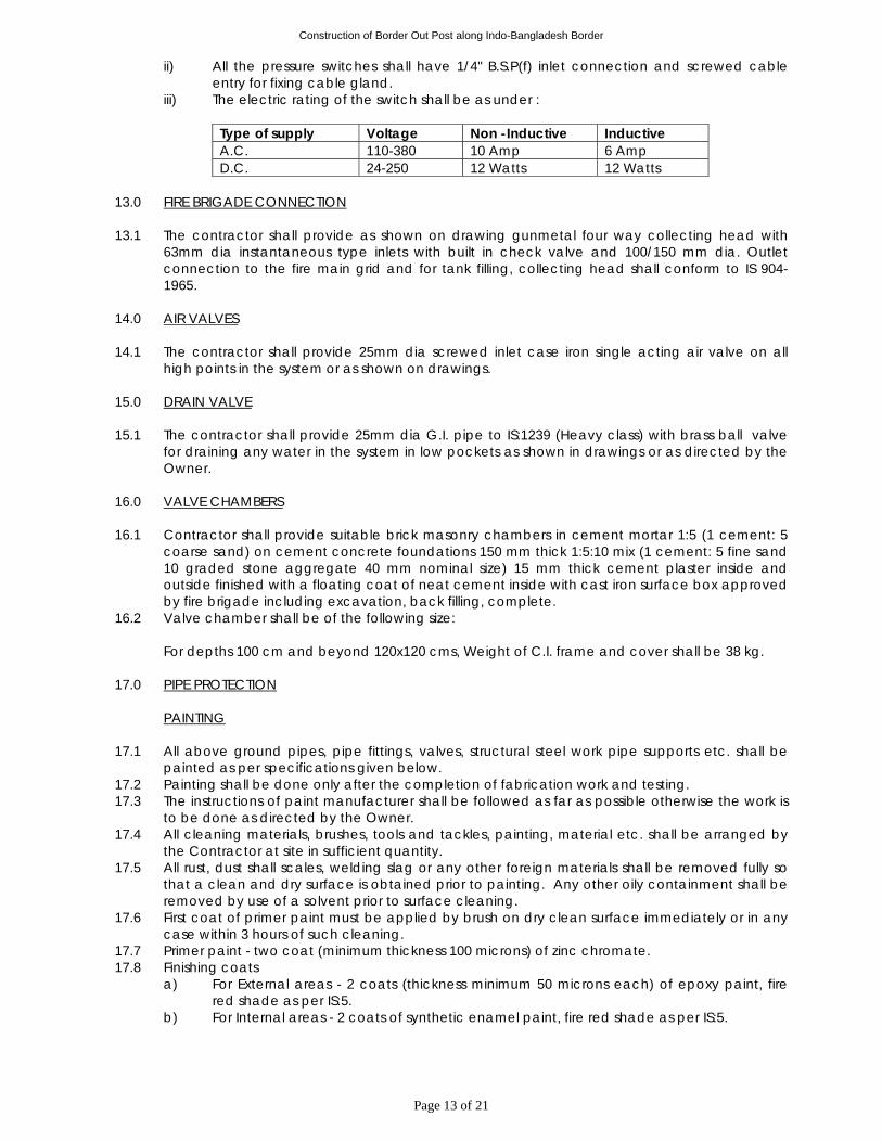
Construction of Border Out Post along Indo-Bangladesh Border
Page 13 of 21
ii) All the pressure switches shall have 1/4" B.S.P(f) inlet connection and screwed cable entry for fixing cable gland.
iii) The electric rating of the switch shall be as under :
Type of supply Voltage Non -Inductive Inductive A.C. 110-380 10 Amp 6 Amp D.C. 24-250 12 Watts 12 Watts
13.0 FIRE BRIGADE CONNECTION
13.1 The contractor shall provide as shown on drawing gunmetal four way collecting head with
63mm dia instantaneous type inlets with built in check valve and 100/150 mm dia. Outlet connection to the fire main grid and for tank filling, collecting head shall conform to IS 904-1965.
14.0 AIR VALVES
14.1 The contractor shall provide 25mm dia screwed inlet case iron single acting air valve on all
high points in the system or as shown on drawings. 15.0 DRAIN VALVE
15.1 The contractor shall provide 25mm dia G.I. pipe to IS:1239 (Heavy class) with brass ball valve
for draining any water in the system in low pockets as shown in drawings or as directed by the Owner.
16.0 VALVE CHAMBERS
16.1 Contractor shall provide suitable brick masonry chambers in cement mortar 1:5 (1 cement: 5
coarse sand) on cement concrete foundations 150 mm thick 1:5:10 mix (1 cement: 5 fine sand 10 graded stone aggregate 40 mm nominal size) 15 mm thick cement plaster inside and outside finished with a floating coat of neat cement inside with cast iron surface box approved by fire brigade including excavation, back filling, complete.
16.2 Valve chamber shall be of the following size: For depths 100 cm and beyond 120x120 cms, Weight of C.I. frame and cover shall be 38 kg.
17.0 PIPE PROTECTION
PAINTING 17.1 All above ground pipes, pipe fittings, valves, structural steel work pipe supports etc. shall be
painted as per specifications given below. 17.2 Painting shall be done only after the completion of fabrication work and testing. 17.3 The instructions of paint manufacturer shall be followed as far as possible otherwise the work is
to be done as directed by the Owner. 17.4 All cleaning materials, brushes, tools and tackles, painting, material etc. shall be arranged by
the Contractor at site in sufficient quantity. 17.5 All rust, dust shall scales, welding slag or any other foreign materials shall be removed fully so
that a clean and dry surface is obtained prior to painting. Any other oily containment shall be removed by use of a solvent prior to surface cleaning.
17.6 First coat of primer paint must be applied by brush on dry clean surface immediately or in any case within 3 hours of such cleaning.
17.7 Primer paint - two coat (minimum thickness 100 microns) of zinc chromate. 17.8 Finishing coats
a) For External areas - 2 coats (thickness minimum 50 microns each) of epoxy paint, fire red shade as per IS:5.
b) For Internal areas - 2 coats of synthetic enamel paint, fire red shade as per IS:5.
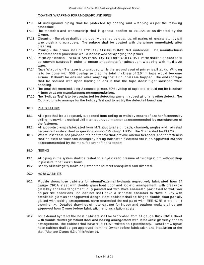
Construction of Border Out Post along Indo-Bangladesh Border
Page 14 of 21
COATING WRAPPING FOR UNDERGROUND PIPES 17.9 All underground piping shall be protected by coating and wrapping as per the following
procedure. 17.10 The materials and workmanship shall in general confirm to IS:10221 or as directed by the
Owner. 17.11 Cleaning - The pipes shall be thoroughly cleaned by dust, rust will scales, oil, grease etc. by stiff
wire brush and scrappers. The surface shall be coated with the primer immediately after cleaning.
17.12 Priming - The primer shall be PYPKOTE/RUSTFIRE/CORPORATE undercoat. The manufacturers recommended procedure would be followed for applying the primer.
17.13 Paste Application - PYPKOTE-AW Paste/RUSTFIRE Paste/CORPORATE Paste shall be applied to fill up uneven surfaces in order to ensure smoothness for subsequent wrapping with multi-layer tape.
17.14 Tape Wrapping - The tape is to wrapped while the second coat of primer is still tacky. Winding is to be done with 50% overlap so that the total thickness of 2.0mm tape would become 4.0mm. It should be ensured while wrapping that air bubbles are trapped. The ends of tape shall be secured with nylon binding to ensure that the tape doesn’t get loosened while handling.
17.15 The total thickness including 2 coats of primer, 50% overlap of tape etc. should not be less than 4.5mm or as per manufacturers recommendations.
17.16 The ‘Holiday Test’ is to be conducted for detecting any entrapped air or any other defect. The Contractor is to arrange for the Holiday Test and to rectify the defects if found any.
18.0 PIPE SUPPORTS
18.1 All pipes shall be adequately supported from ceiling or walls by means of anchor fasteners by
drilling holes with electrical drill in an approved manner as recommended by manufacturer of the fasteners.
18.2 All supports/clamps fabricated from M.S. structural e.g. roads, channels, angles and flats shall be painted as described in specifications for “Painting” ABOVE. The Shade shall be BLACK.
18.3 Where inserts are not provided the contractor shall provide anchor fasteners. Anchor fasteners shall be fixed to walls and ceilings by drilling holes with electrical drill in an approved manner as recommended by the manufacturer of the fasteners
19.0 TESTING
19.1 All piping in the system shall be tested to a hydrostatic pressure of 14.0 kg/sq.cm without drop
in pressure for at least 2 hours. 19.2 Rectify all leakage’s, make adjustments and reset as required and directed. 20.0 HOSE CABINETS
20.1 Provide doors/hose cabinets for internal/external hydrants respectively fabricated from 14
gauge CRCA sheet with double glass front door and locking arrangement, with breakable glass key access arrangement, duly painted red with stove enameled paint fixed to wall floor as per site conditions. The cabinet shall have a separate chamber to stove a key with breakable glass as per approved design. Hose cabinets shall be hinged double door partially glazed with locking arrangement, stove enameled fire red paint with ‘FIRE HOSE’ written on it prominently. Detailed drawings of hose cabinet for indoor and outdoor works shall be got approved from Owner before fabrication and installation at site.
20.2 For external hydrants the hose cabinets shall be fabricated from 14 gauge thick CRCA sheet
with double shutter glass front door and locking arrangement with breakable glass key access arrangement. The cabinet shall have ‘FIRE HOSE” written on it prominently. Detail drawings of hose cabinet shall be got approved from the Owner before fabrication and installation at the site. (Also see Clause 9.3 of this Volume).
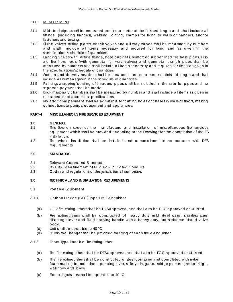
Construction of Border Out Post along Indo-Bangladesh Border
Page 15 of 21
21.0 MEASUREMENT
21.1 Mild steel pipes shall be measured per linear meter of the finished length and shall include all
fittings (including flanges), welding, jointing, clamps for fixing to walls or hangers, anchor fasteners and testing.
21.2 Sluice valves, orifice plates, check valves and full way valves shall be measured by numbers and shall include all items necessary and required for fixing and as given in the specifications/schedule of quantities.
21.3 Landing valves with orifice flange, hose cabinets, reinforced rubber lined fire hose pipes, First-aid fire hose reels (with gunmetal full way valves) and gunmetal branch pipes shall be measured by numbers and shall include all items necessary and required for fixing as given in the specifications/schedule of quantities.
21.4 Suction and delivery headers shall be measured per linear meter or finished length and shall include all items as given in the schedule of quantities.
21.5 Painting/wrapping/coating of headers, pipes shall be included in the rate for pipes and no separate payment shall be made.
21.6 Brick masonary chambers shall be measured by number and shall include all items as given in the schedule of quantities/specifications.
21.7 No additional payment shall be admissible for cutting holes or chases in walls or floors, making connections to pumps, equipment and appliances.
PART-4 MISCELLANEOUS FIRE SERVICES EQUIPMENT 1.0 GENERAL 1.1 This Section specifies the manufacture and installation of miscellaneous fire services
equipment which shall be provided according to the Drawings for the completion of the FS installation.
1.2 The whole installation shall be installed and commissioned in accordance with DFS requirements.
2.0 STANDARDS 2.1 Relevant Codes and Standards 2.2 BS 1042: Measurement of Fluid Flow in Closed Conduits 2.3 Codes and regulations of the jurisdictional authorities
3.0 TECHNICAL AND INSTALLATION REQUIREMENTS 3.1 Portable Equipment 3.1.1 Carbon Dioxide (CO2) Type Fire Extinguisher
(a) CO2 fire extinguishers shall be DFS approved, and shall also be FOC approved or UL listed.
(b) Fire extinguishers shall be constructed of heavy duty mild steel case, stainless steel discharge lever and fixed carrying handle with a heavy duty, brass chrome-plated valve body.
(c) Unit shall be operable to 40 °C. (d) Sturdy wall hanger shall be provided for fixing of each fire extinguisher.
3.1.2 Foam Type Portable Fire Extinguisher
(a) The fire extinguishers shall be DFS approved, and shall also be FOC approved or UL listed.
(b) The fire extinguishers shall be constructed of steel container and completed with nylon foam making branch pipe, operating lever, safety pin, gas cartridge piercer, gas cartridge, wall hook and screw.
(c) Fire extinguishers shall be operable to 40 °C.
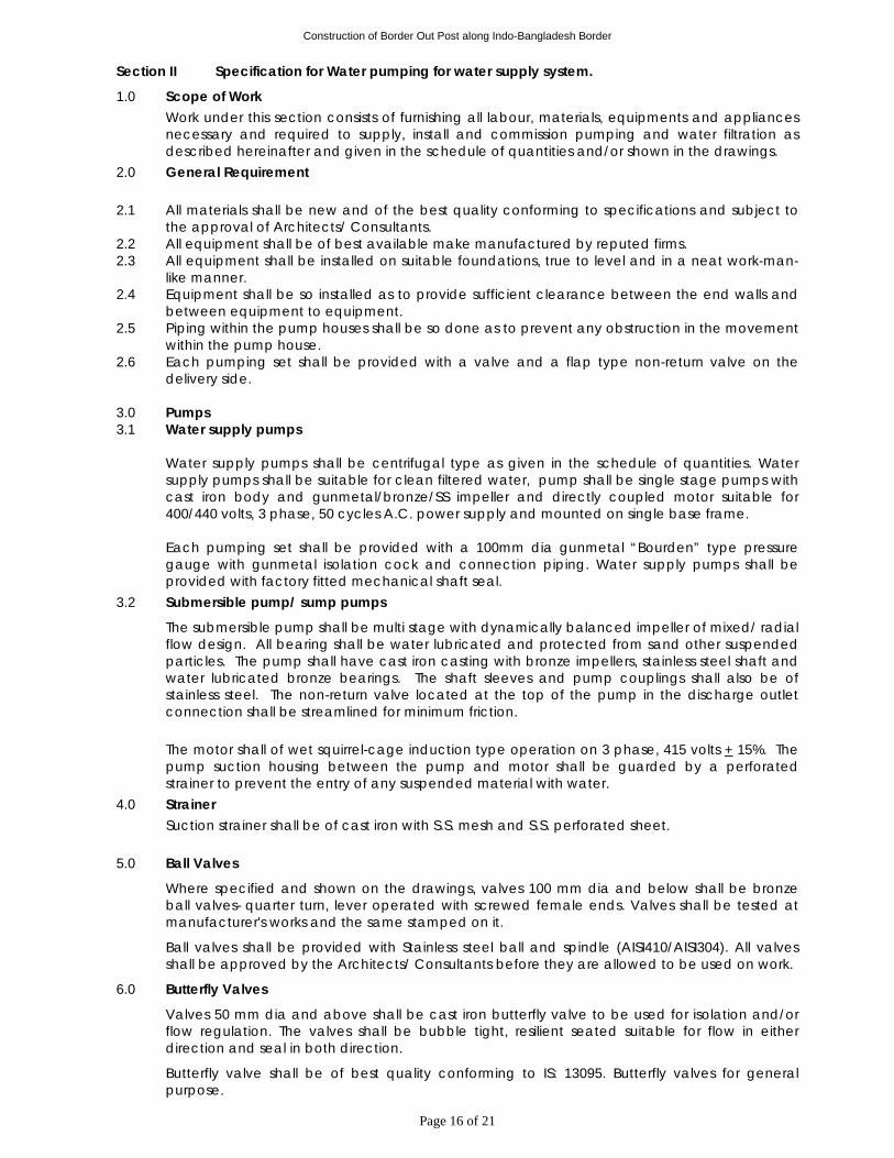
Construction of Border Out Post along Indo-Bangladesh Border
Page 16 of 21
Section II Specification for Water pumping for water supply system.
1.0 Scope of Work Work under this section consists of furnishing all labour, materials, equipments and appliances necessary and required to supply, install and commission pumping and water filtration as described hereinafter and given in the schedule of quantities and/or shown in the drawings.
2.0 General Requirement 2.1 All materials shall be new and of the best quality conforming to specifications and subject to
the approval of Architects/ Consultants. 2.2 All equipment shall be of best available make manufactured by reputed firms. 2.3 All equipment shall be installed on suitable foundations, true to level and in a neat work-man-
like manner. 2.4 Equipment shall be so installed as to provide sufficient clearance between the end walls and
between equipment to equipment. 2.5 Piping within the pump houses shall be so done as to prevent any obstruction in the movement
within the pump house. 2.6 Each pumping set shall be provided with a valve and a flap type non-return valve on the
delivery side. 3.0 Pumps 3.1 Water supply pumps
Water supply pumps shall be centrifugal type as given in the schedule of quantities. Water supply pumps shall be suitable for clean filtered water, pump shall be single stage pumps with cast iron body and gunmetal/bronze/SS impeller and directly coupled motor suitable for 400/440 volts, 3 phase, 50 cycles A.C. power supply and mounted on single base frame. Each pumping set shall be provided with a 100mm dia gunmetal “Bourden” type pressure gauge with gunmetal isolation cock and connection piping. Water supply pumps shall be provided with factory fitted mechanical shaft seal.
3.2 Submersible pump/ sump pumps
The submersible pump shall be multi stage with dynamically balanced impeller of mixed/ radial flow design. All bearing shall be water lubricated and protected from sand other suspended particles. The pump shall have cast iron casting with bronze impellers, stainless steel shaft and water lubricated bronze bearings. The shaft sleeves and pump couplings shall also be of stainless steel. The non-return valve located at the top of the pump in the discharge outlet connection shall be streamlined for minimum friction. The motor shall of wet squirrel-cage induction type operation on 3 phase, 415 volts + 15%. The pump suction housing between the pump and motor shall be guarded by a perforated strainer to prevent the entry of any suspended material with water.
4.0 Strainer Suction strainer shall be of cast iron with S.S. mesh and S.S. perforated sheet.
5.0 Ball Valves
Where specified and shown on the drawings, valves 100 mm dia and below shall be bronze ball valves- quarter turn, lever operated with screwed female ends. Valves shall be tested at manufacturer's works and the same stamped on it.
Ball valves shall be provided with Stainless steel ball and spindle (AISI410/AISI304). All valves shall be approved by the Architects/ Consultants before they are allowed to be used on work.
6.0 Butterfly Valves
Valves 50 mm dia and above shall be cast iron butterfly valve to be used for isolation and/or flow regulation. The valves shall be bubble tight, resilient seated suitable for flow in either direction and seal in both direction.
Butterfly valve shall be of best quality conforming to IS: 13095. Butterfly valves for general purpose.
Construction of Border Out Post along Indo-Bangladesh Border
Page 17 of 21
7.0 Non Return Valve
Where specified non return valve (Dual plate check type for 50 NB and above and spring loaded, Uni directional type for size less than 50 NB) shall be provided through which flow can occur in one direction only. It shall be of best quality conforming to IS: 5312
8.0 Operation and Maintenance
The bidder shall train the Owner’s staff for the operation and maintenance of the plant after successful commissioning.
9.0 Inspection and Testing
All equipment and individual items which form a part of the Treatment Plant shall be manufactured under a strict approved quality assurance plan. The bidder shall submit the Quality Assurance Plan (QAP) along with the offer and in case of order the QAP shall be mutually finalized within one week of the LOI/Order and all equipment’s items and will be subjected to inspection as per the QAP. Access to the manufacturer shop of the bidder or their sub vendor’s at all reasonable times shall be made available to Owners/Consultants representatives.
10.0 Guarantee
The vendor shall guarantee the Water supply system to perform as per stated and specified for a period of 12 months from the date of commissioning or 18 months from the date of mechanical readiness of the plant after pre-commissioning tests, whichever is earlier. In case of any shortfall in the plant performance the vendor shall undertake to repair/rectify and make good the same at his own cost to achieve the specified duty conditions. The Water Treatment Plant shall be guarantee against. - Non performance in either achieving the quantity through put or in achieving the treated
water quality. - Inadequate design. - Improper materials and workmanship.
11.0 Document to be provided by Bidders
Along with technical bid
a) Technical and commercial bid comprising technical and commercial offer with the following documents which must be submitted with the technical bid.
b) Process description supplement with a process flow diagram and with deviations, if any from the detailed specifications as given above.
c) Filled up utilities, consumable and performance guarantee data sheets.
Along with priced bid (in separate sealed cover with the bid) The prices bid shall be enclosed in a separate sealed cover and the price bid shall not contain any commercial terms or conditions. In case it contains any commercial terms or conditions the bid is liable to be rejected or the terms and conditions shall not be considered at the option of the Owner. After placement of order After placement of order the vendor to submit the following within 15 days in six copies.
a) Process flow diagram and P&I diagram. b) General arrangement and drawing of the units with nozzle locations, insert locations
and with load data, whichever applicable. c) Piping Layout d) Electrical load list, single lines diagram and cable routing drawing. e) Civil and structural drawings with design calculations. f) Six copies of the operation and maintenance manual prior start of commissioning
of plant.
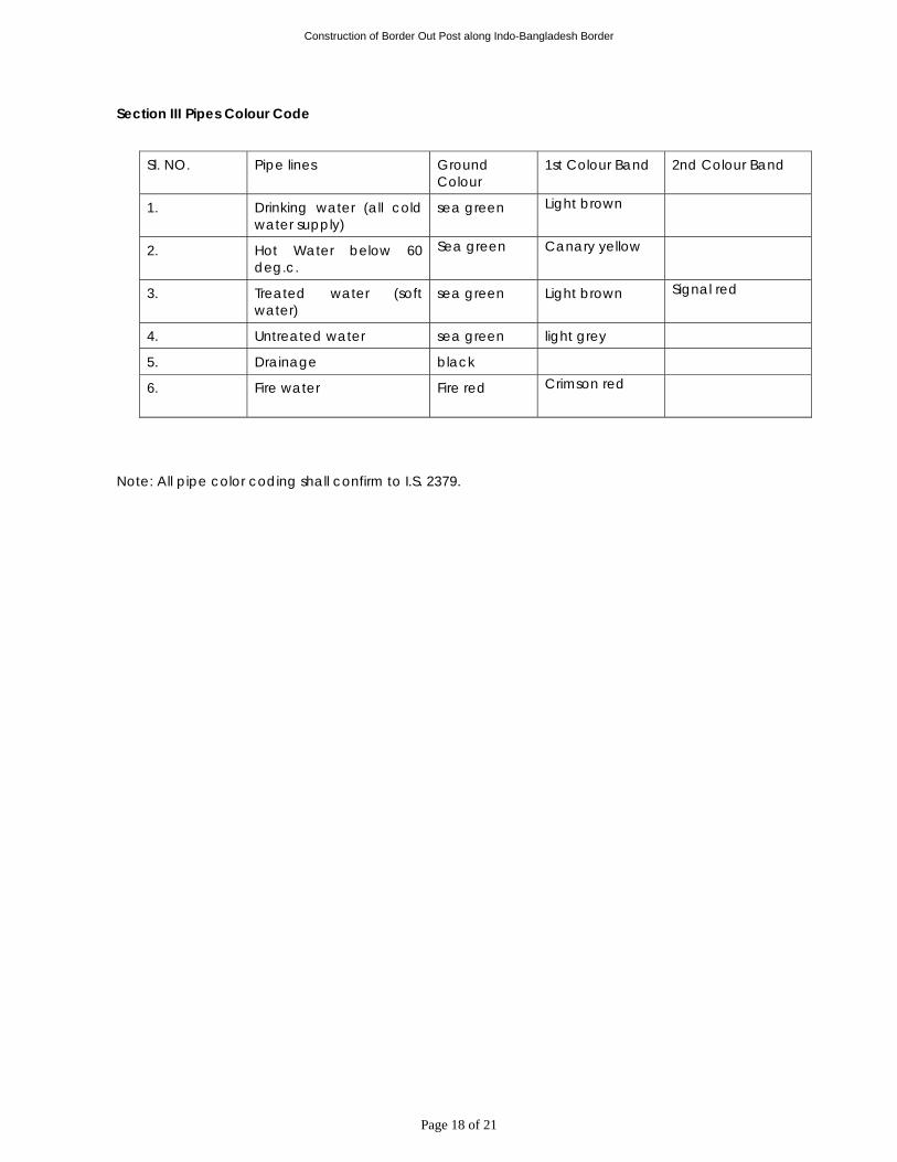
Construction of Border Out Post along Indo-Bangladesh Border
Page 18 of 21
Section III Pipes Colour Code
Sl. NO. Pipe lines Ground Colour
1st Colour Band 2nd Colour Band
1. Drinking water (all cold water supply)
sea green Light brown
2. Hot Water below 60 deg.c.
Sea green
Canary yellow
3. Treated water (soft water)
sea green Light brown Signal red
4. Untreated water sea green light grey
5. Drainage black
6. Fire water Fire red Crimson red
Note: All pipe color coding shall confirm to I.S. 2379.
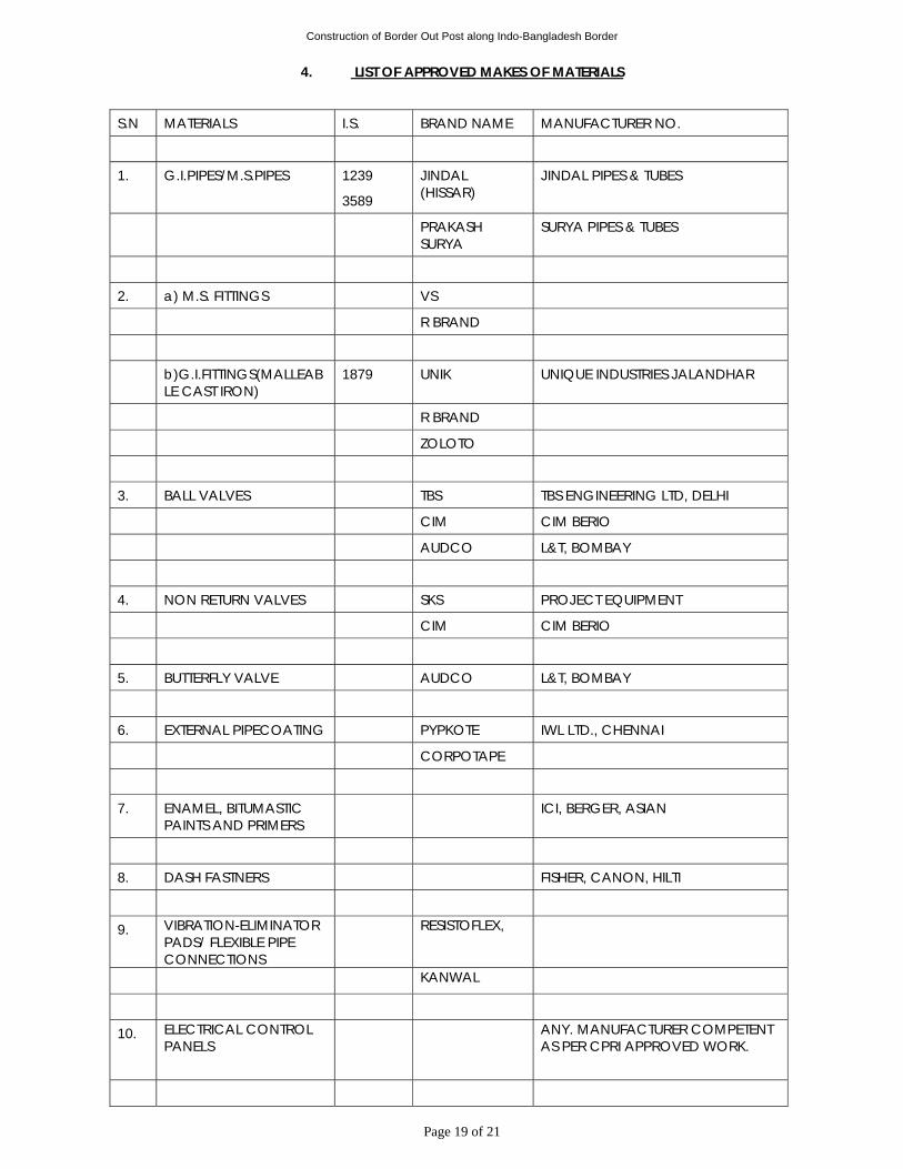
Construction of Border Out Post along Indo-Bangladesh Border
Page 19 of 21
4. LIST OF APPROVED MAKES OF MATERIALS
S.N MATERIALS I.S. BRAND NAME MANUFACTURER NO.
1. G.I.PIPES/M.S.PIPES 1239
3589
JINDAL (HISSAR)
JINDAL PIPES & TUBES
PRAKASH SURYA
SURYA PIPES & TUBES
2. a) M.S. FITTINGS VS
R BRAND
b)G.I.FITTINGS(MALLEABLE CAST IRON)
1879 UNIK UNIQUE INDUSTRIES JALANDHAR
R BRAND
ZOLOTO
3. BALL VALVES TBS TBS ENGINEERING LTD, DELHI
CIM CIM BERIO
AUDCO L&T, BOMBAY
4. NON RETURN VALVES SKS PROJECT EQUIPMENT
CIM CIM BERIO
5. BUTTERFLY VALVE AUDCO L&T, BOMBAY
6. EXTERNAL PIPECOATING PYPKOTE IWL LTD., CHENNAI
CORPOTAPE
7. ENAMEL, BITUMASTIC PAINTS AND PRIMERS
ICI, BERGER, ASIAN
8. DASH FASTNERS FISHER, CANON, HILTI
9. VIBRATION-ELIMINATOR PADS/ FLEXIBLE PIPE CONNECTIONS
RESISTOFLEX,
KANWAL
10. ELECTRICAL CONTROL PANELS
ANY. MANUFACTURER COMPETENT AS PER CPRI APPROVED WORK.
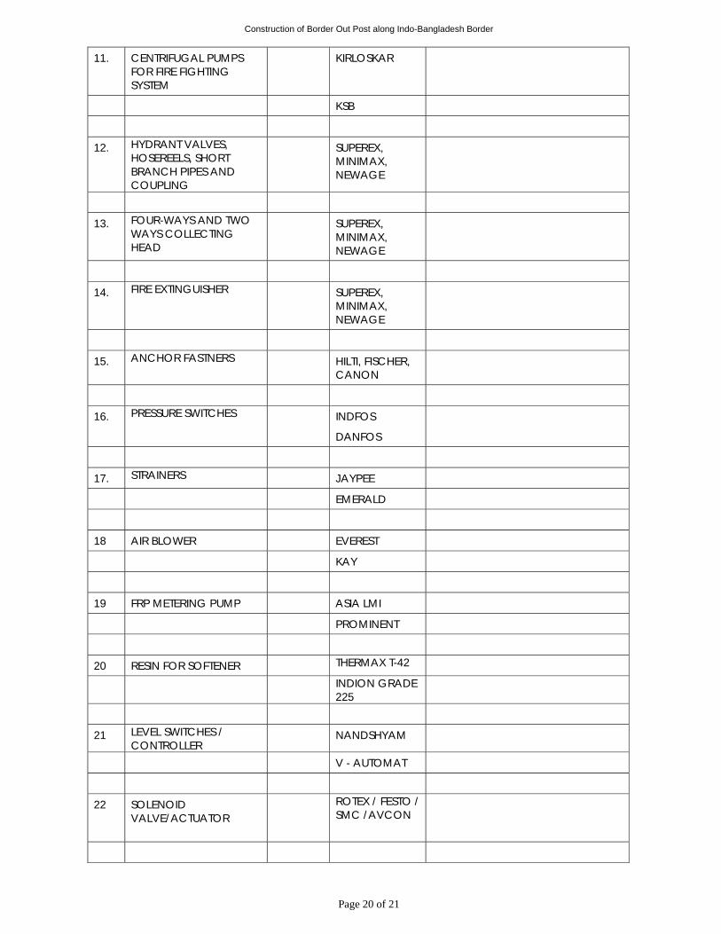
Construction of Border Out Post along Indo-Bangladesh Border
Page 20 of 21
11. CENTRIFUGAL PUMPS FOR FIRE FIGHTING SYSTEM
KIRLOSKAR
KSB
12. HYDRANT VALVES, HOSEREELS, SHORT BRANCH PIPES AND COUPLING
SUPEREX, MINIMAX, NEWAGE
13. FOUR-WAYS AND TWO WAYS COLLECTING HEAD
SUPEREX, MINIMAX, NEWAGE
14. FIRE EXTINGUISHER SUPEREX, MINIMAX, NEWAGE
15. ANCHOR FASTNERS HILTI, FISCHER, CANON
16. PRESSURE SWITCHES INDFOS
DANFOS
17. STRAINERS JAYPEE
EMERALD
18 AIR BLOWER EVEREST
KAY
19 FRP METERING PUMP ASIA LMI
PROMINENT
20 RESIN FOR SOFTENER THERMAX T-42
INDION GRADE 225
21 LEVEL SWITCHES / CONTROLLER
NANDSHYAM
V - AUTOMAT
22 SOLENOID VALVE/ACTUATOR
ROTEX / FESTO / SMC /AVCON
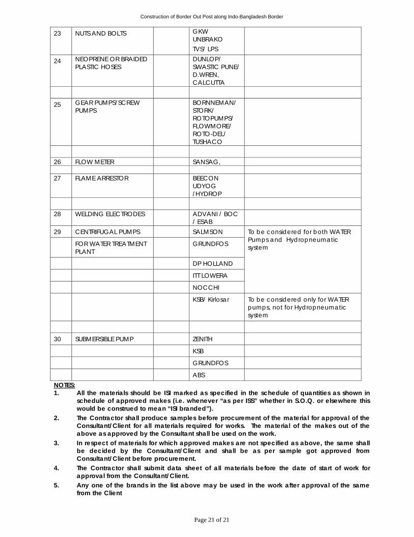
Construction of Border Out Post along Indo-Bangladesh Border
Page 21 of 21
23 NUTS AND BOLTS GKW UNBRAKO TVS/ LPS
24 NEOPRENE OR BRAIDED PLASTIC HOSES
DUNLOP/ SWASTIC PUNE/ D.WREN, CALCUTTA
25 GEAR PUMPS/SCREW PUMPS
BORNNEMAN/ STORK/ ROTOPUMPS/ FLOWMORE/ ROTO-DEL/ TUSHACO
26 FLOW METER SANSAG, 27 FLAME ARRESTOR BEECON
UDYOG /HYDROP
28 WELDING ELECTRODES ADVANI / BOC
/ ESAB
29 CENTRIFUGAL PUMPS SALMSON
FOR WATER TREATMENT PLANT
GRUNDFOS
DP HOLLAND
ITT LOWERA
NOCCHI
To be considered for both WATER Pumps and Hydropneumatic system
KSB/ Kirlosar To be considered only for WATER pumps, not for Hydropneumatic system
30 SUBMERSIBLE PUMP ZENITH
KSB
GRUNDFOS
ABS NOTES: 1. All the materials should be ISI marked as specified in the schedule of quantities as shown in
schedule of approved makes (i.e. whenever “as per ISS” whether in S.O.Q. or elsewhere this would be construed to mean “ISI branded”).
2. The Contractor shall produce samples before procurement of the material for approval of the Consultant/Client for all materials required for works. The material of the makes out of the above as approved by the Consultant shall be used on the work.
3. In respect of materials for which approved makes are not specified as above, the same shall be decided by the Consultant/Client and shall be as per sample got approved from Consultant/Client before procurement.
4. The Contractor shall submit data sheet of all materials before the date of start of work for approval from the Consultant/Client.
5. Any one of the brands in the list above may be used in the work after approval of the same from the Client
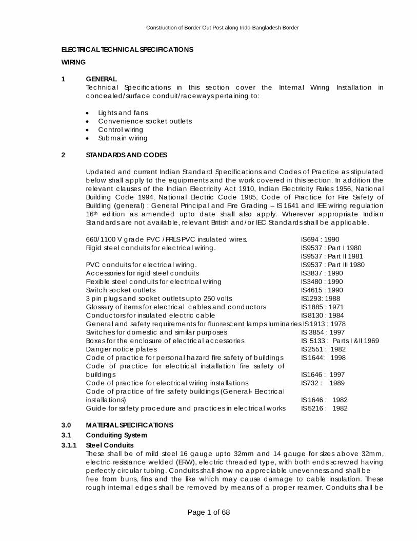
Construction of Border Out Post along Indo-Bangladesh Border
Page 1 of 68
ELECTRICAL TECHNICAL SPECIFICATIONS
WIRING 1 GENERAL
Technical Specifications in this section cover the Internal Wiring Installation in concealed/surface conduit/raceways pertaining to:
• Lights and fans • Convenience socket outlets • Control wiring • Submain wiring
2 STANDARDS AND CODES
Updated and current Indian Standard Specifications and Codes of Practice as stipulated below shall apply to the equipments and the work covered in this section. In addition the relevant clauses of the Indian Electricity Act 1910, Indian Electricity Rules 1956, National Building Code 1994, National Electric Code 1985, Code of Practice for Fire Safety of Building (general) : General Principal and Fire Grading – IS 1641 and IEE wiring regulation 16th edition as amended upto date shall also apply. Wherever appropriate Indian Standards are not available, relevant British and/or IEC Standards shall be applicable. 660/1100 V grade PVC /FRLS PVC insulated wires. IS 694 : 1990 Rigid steel conduits for electrical wiring. IS 9537 : Part I 1980 IS 9537 : Part II 1981 PVC conduits for electrical wiring. IS 9537 : Part III 1980 Accessories for rigid steel conduits IS 3837 : 1990 Flexible steel conduits for electrical wiring IS 3480 : 1990 Switch socket outlets IS 4615 : 1990 3 pin plugs and socket outlets upto 250 volts IS1293: 1988 Glossary of items for electrical cables and conductors IS 1885 : 1971 Conductors for insulated electric cable IS 8130 : 1984 General and safety requirements for fluorescent lamps luminaries IS 1913 : 1978 Switches for domestic and similar purposes IS 3854 : 1997 Boxes for the enclosure of electrical accessories IS 5133 : Parts I &II 1969 Danger notice plates IS 2551 : 1982 Code of practice for personal hazard fire safety of buildings IS 1644: 1998 Code of practice for electrical installation fire safety of buildings IS 1646 : 1997 Code of practice for electrical wiring installations IS 732 : 1989 Code of practice of fire safety buildings (General- Electrical installations) IS 1646 : 1982 Guide for safety procedure and practices in electrical works IS 5216 : 1982
3.0 MATERIAL SPECIFICATIONS
3.1 Conduiting System
3.1.1 Steel Conduits These shall be of mild steel 16 gauge upto 32mm and 14 gauge for sizes above 32mm, electric resistance welded (ERW), electric threaded type, with both ends screwed having perfectly circular tubing. Conduits shall show no appreciable unevenness and shall be free from burrs, fins and the like which may cause damage to cable insulation. These rough internal edges shall be removed by means of a proper reamer. Conduits shall be
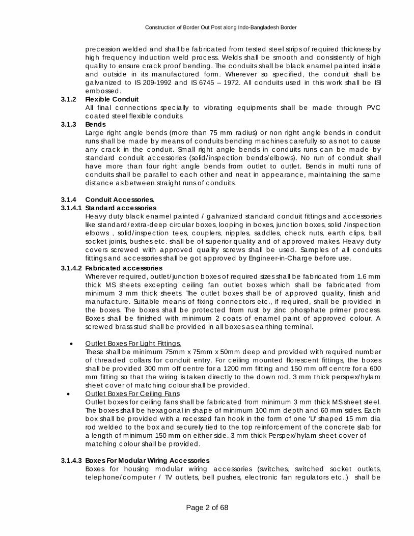
Construction of Border Out Post along Indo-Bangladesh Border
Page 2 of 68
precession welded and shall be fabricated from tested steel strips of required thickness by high frequency induction weld process. Welds shall be smooth and consistently of high quality to ensure crack proof bending. The conduits shall be black enamel painted inside and outside in its manufactured form. Wherever so specified, the conduit shall be galvanized to IS 209-1992 and IS 6745 – 1972. All conduits used in this work shall be ISI embossed.
3.1.2 Flexible Conduit All final connections specially to vibrating equipments shall be made through PVC coated steel flexible conduits.
3.1.3 Bends Large right angle bends (more than 75 mm radius) or non right angle bends in conduit runs shall be made by means of conduits bending machines carefully so as not to cause any crack in the conduit. Small right angle bends in conduits runs can be made by standard conduit accessories (solid/inspection bends/elbows). No run of conduit shall have more than four right angle bends from outlet to outlet. Bends in multi runs of conduits shall be parallel to each other and neat in appearance, maintaining the same distance as between straight runs of conduits.
3.1.4 Conduit Accessories. 3.1.4.1 Standard accessories
Heavy duty black enamel painted / galvanized standard conduit fittings and accessories like standard/extra-deep circular boxes, looping in boxes, junction boxes, solid /inspection elbows , solid/inspection tees, couplers, nipples, saddles, check nuts, earth clips, ball socket joints, bushes etc. shall be of superior quality and of approved makes. Heavy duty covers screwed with approved quality screws shall be used. Samples of all conduits fittings and accessories shall be got approved by Engineer-in-Charge before use.
3.1.4.2 Fabricated accessories Wherever required, outlet/junction boxes of required sizes shall be fabricated from 1.6 mm thick MS sheets excepting ceiling fan outlet boxes which shall be fabricated from minimum 3 mm thick sheets. The outlet boxes shall be of approved quality, finish and manufacture. Suitable means of fixing connectors etc., if required, shall be provided in the boxes. The boxes shall be protected from rust by zinc phosphate primer process. Boxes shall be finished with minimum 2 coats of enamel paint of approved colour. A screwed brass stud shall be provided in all boxes as earthing terminal.
• Outlet Boxes For Light Fittings.
These shall be minimum 75mm x 75mm x 50mm deep and provided with required number of threaded collars for conduit entry. For ceiling mounted florescent fittings, the boxes shall be provided 300 mm off centre for a 1200 mm fitting and 150 mm off centre for a 600 mm fitting so that the wiring is taken directly to the down rod. 3 mm thick perspex/hylam sheet cover of matching colour shall be provided.
• Outlet Boxes For Ceiling Fans Outlet boxes for ceiling fans shall be fabricated from minimum 3 mm thick MS sheet steel. The boxes shall be hexagonal in shape of minimum 100 mm depth and 60 mm sides. Each box shall be provided with a recessed fan hook in the form of one 'U' shaped 15 mm dia rod welded to the box and securely tied to the top reinforcement of the concrete slab for a length of minimum 150 mm on either side. 3 mm thick Perspex/hylam sheet cover of matching colour shall be provided.
3.1.4.3 Boxes For Modular Wiring Accessories
Boxes for housing modular wiring accessories (switches, switched socket outlets, telephone/computer / TV outlets, bell pushes, electronic fan regulators etc..) shall be
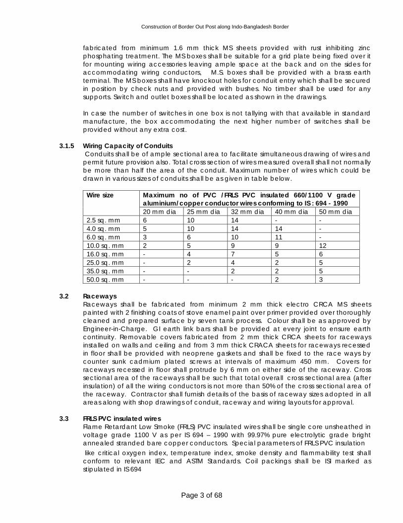
Construction of Border Out Post along Indo-Bangladesh Border
Page 3 of 68
fabricated from minimum 1.6 mm thick MS sheets provided with rust inhibiting zinc phosphating treatment. The MS boxes shall be suitable for a grid plate being fixed over it for mounting wiring accessories leaving ample space at the back and on the sides for accommodating wiring conductors, M.S. boxes shall be provided with a brass earth terminal. The MS boxes shall have knockout holes for conduit entry which shall be secured in position by check nuts and provided with bushes. No timber shall be used for any supports. Switch and outlet boxes shall be located as shown in the drawings. In case the number of switches in one box is not tallying with that available in standard manufacture, the box accommodating the next higher number of switches shall be provided without any extra cost.
3.1.5 Wiring Capacity of Conduits
Conduits shall be of ample sectional area to facilitate simultaneous drawing of wires and permit future provision also. Total cross section of wires measured overall shall not normally be more than half the area of the conduit. Maximum number of wires which could be drawn in various sizes of conduits shall be as given in table below.
Maximum no of PVC /FRLS PVC insulated 660/1100 V grade aluminium/copper conductor wires conforming to IS : 694 - 1990
Wire size
20 mm dia 25 mm dia 32 mm dia 40 mm dia 50 mm dia 2.5 sq. mm 6 10 14 - - 4.0 sq. mm 5 10 14 14 - 6.0 sq. mm 3 6 10 11 - 10.0 sq. mm 2 5 9 9 12 16.0 sq. mm - 4 7 5 6 25.0 sq. mm - 2 4 2 5 35.0 sq. mm - - 2 2 5 50.0 sq. mm - - - 2 3
3.2 Raceways
Raceways shall be fabricated from minimum 2 mm thick electro CRCA MS sheets painted with 2 finishing coats of stove enamel paint over primer provided over thoroughly cleaned and prepared surface by seven tank process. Colour shall be as approved by Engineer-in-Charge. GI earth link bars shall be provided at every joint to ensure earth continuity. Removable covers fabricated from 2 mm thick CRCA sheets for raceways installed on walls and ceiling and from 3 mm thick CRACA sheets for raceways recessed in floor shall be provided with neoprene gaskets and shall be fixed to the race ways by counter sunk cadmium plated screws at intervals of maximum 450 mm. Covers for raceways recessed in floor shall protrude by 6 mm on either side of the raceway. Cross sectional area of the raceways shall be such that total overall cross sectional area (after insulation) of all the wiring conductors is not more than 50% of the cross sectional area of the raceway. Contractor shall furnish details of the basis of raceway sizes adopted in all areas along with shop drawings of conduit, raceway and wiring layouts for approval.
3.3 FRLS PVC insulated wires
Flame Retardant Low Smoke (FRLS) PVC insulated wires shall be single core unsheathed in voltage grade 1100 V as per IS 694 – 1990 with 99.97% pure electrolytic grade bright annealed stranded bare copper conductors. Special parameters of FRLS PVC insulation
like critical oxygen index, temperature index, smoke density and flammability test shall conform to relevant IEC and ASTM Standards. Coil packings shall be ISI marked as stipulated in IS 694
Construction of Border Out Post along Indo-Bangladesh Border
Page 4 of 68
3.4. Modular Cover Plated Mounted Wiring Accessories 3.4.1 Switches
All 6 and 16 amps switches shall be of the modular enclosed type flush mounted 220 Volt AC of the best quality and standard. The switch moving and fixed contacts shall be of silver nickel and silver graphite alloy and contact tips coated with silver. The housing of switches shall be made from high impact resistant, flame retarding and ultra violet stabilized engineering plastic material. The switch controlling the light point shall be connected on to the phase wire of the circuit.
3.4.2 Molded Cover Plates
Switches, receptacles and telephone system outlets in wall shall be provided with molded cover plates of shape, size and colour approved by the Engineer-in-Charge made from high impact resistant, flame retarding and ultra violet stabilized engineering plastic material, and secured to the box with counter sunk round head chromium plated brass screws. Where two or more switches are installed together, they shall be provided with one common switch cover plate as described above with notches to accommodate all switches either in one, two or three rows. One and two gang switch cover plate, telephone outlet cover plate, 6 and 16 amps switched/unswitched plates shall have the same shape and size. Three and four gang switch cover plates shall have the same shape and size. Six and eight gang switch cover plates shall have the same shape and size. Nine and twelve switch cover plates shall have the same shape and size. Wherever five switches, seven switches, ten switches and eleven switches are to be fixed the next higher size of gang switch cover plate to be used and openings shall be provided with blank-off covers at no extra cost.
3.4.3 Wall Socket Outlets
All 6/16 amps wall socket outlets unless otherwise mentioned on the drawings shall be switched, with round pins and fitted with automatic linear safety shutters to ensure safety from prying fingers. Unswitched 6/16 amp wall socket outlets where called for in the drawings shall be of three pin type. The socket outlets shall be made from high impact resistant, flame retarding and ultra violet stabilized engineering plastic material. The switch and sockets shall be located in the same plate. The plates for 6 amp switched/unswitched plugs and telephone outlets shall be of the same size and shape. All the switched and unswitched outlets shall be of the best standard. The switch controlling the socket outlet shall be on the phase wire of the circuit. An earth wire shall be provided along the cables feeding socket outlets for electrical appliances. The earth wire shall be connected to the earthing terminal screw inside the box. The earth terminal of the socket shall be connected to the earth terminal provided inside the box.
4 CONDUIT INSTALLATION 4.1 System
The whole conduit system shall be installed to comply fully with relevant provision in Indian Standard Specifications, Indian Electricity Rules and IE wiring regulations. Conduits shall be laid either recessed in walls and ceilings or on surface on walls and ceilings or partly recessed and partly on surface, as required. Same rate shall apply for recessed and surface conduiting in this contract. Stranded copper conductor insulated wire of size as per schedule of quantities shall be provided in entire conduiting for loop earthing. Steel wire of suitable size to serve as a fish wire shall be left in all conduit runs to facilitate drawing of wires after completion of conduiting.
4.2 Layout
Construction of Border Out Post along Indo-Bangladesh Border
Page 5 of 68
• Conduits layout and routes shall be submitted for Engineer-in-Charge approval prior to
execution. Allowance for adjustments due to site conditions shall be provided with no extra cost.
• Conduit routes shall be chosen for easy, straight runs with a minimum of bends and
crossings. Generally they shall follow the structure of building, running at right angles or in parallels to floors and ceilings. Conduit shall be kept within 300 mm of floors and ceiling when running parallel to them.
• Outlets boxes for housing accessories shall be used as draw boxes. The total number of
draw boxes shall be kept to a minimum and shall be provided so that conduits runs do not exceed 12 m or have more than two right angle bends.
• All conduits shall be kept clear of gas and water pipes. In particulars, conduits shall be at
least 150 mm away from gas pipe. Where proximity to these pipes is unavoidable, they shall be effectually segregated e.g. using rubber or other insulating material to prevent appreciable voltage difference at possible points of contact. Segregation from extra low voltage circuits and telecommunication circuits shall also apply unless these are wired to the same voltage requirements as lighting and power circuits.
• Conduits from different distribution boards shall not be connected to the same junction
box. Each run of conduit shall be assembled complete with draw in wires. 4.3 Joints and terminations • Electrical and mechanical continuity shall be maintained throughout all conduits joints
and terminations. Conduit threads shall be thoroughly cleaned and the conduits tightly screwed. The conduit system shall be watertight after installation.
• Conduits shall be connected using couplers or via boxes. With a coupler, the ends of the
conduit shall butted close together and the running coupler is screwed tightly on and tightened by a locknut.
• Conduits terminating into boxes provided with spouts shall be threaded so that there are
no exposed threads. For boxes with no spouts, the termination shall be made using a brass bush and a coupler. The conduit is pushed through the knockout or drilled entry and the bush is screwed tightly onto its end. The coupler is screwed to butt firmly against the exterior wall of the box.
• Where conduits are not jointed or terminated in boxes, they shall be terminated in a
screwed brass bush. • In all joints and terminations, conduits threads shall not be exposed. Where this cannot be
avoided as in a running coupler, the exposed threads shall be coated with red lead paint to seal against the ingress of water.
4.4 Bends • Conduits shall be bent cold with an approved type of bending block or bending
machine, without altering the dimensions of their sections.
Construction of Border Out Post along Indo-Bangladesh Border
Page 6 of 68
• All conduits bends shall be such as to permit compliance to the requirements for bends in cables to as stated in the IEE regulations
• Bends shall be made with as large a radius as the position of the conduit within the
building permits. Where the bend is more than 90 degree, circular or rectangular junction boxes shall to be used for connecting conduits.
4.5 Recessed Conduiting Conduits recessed in concrete members shall be laid before casting, in the upper portion of slabs or otherwise as may be instructed, so as to embedded the entire run of conduits and ceiling outlet boxes with a cover of minimum 12 mm concrete. Conduits shall be adequately tied to the reinforcement to prevent displacement during casting at intervals of maximum 1 meter. No reinforcement bars shall be cut to fix the conduits. Suitable flexible joints shall be provided at all locations where conduits cross expansion joints in the building.
Conduits recessed in brick work shall be laid in chases to be cut by electrical Contractor in brick work before plastering. The chases shall be cut by a chase cutting electric machine. The chases shall be of sufficient width (minimum 10 mm spacing between adjacent conduit) to accommodate the required number of conduits and of sufficient depth to permit full thickness of plaster (minimum 6 mm) over conduits. The conduits shall be secured in the chase by means of heavy duty pressed steel clamps screwed to MS flat strip saddles at intervals of maximum 1 meter. The chases shall then be filled with cement and coarse sand mortar (1:3) and properly cured by watering. For chases more than 75 mm width, a wiremesh shall be provided for the full length and width of the chase in the plaster to prevent cracking. Junction boxes intended for facilitating drawing of wires in conduiting system shall be located in accessible locations to permit redrawing of wires in future. Open ends of conduits laid in slabs and walls shall be suitably plugged before pouring concrete / plastering to prevent ingress of water / debris in to the conduits Entire recessed conduit work in concrete members and in brick work shall be carried out in close coordination with progress of civil works. Conduits in concrete members shall be laid before casting and conduits in brick work shall be laid before plastering. Should it become necessary to embed conduits in already cast concrete members, suitable chase shall be cut in concrete for the purpose. For minimizing this cutting, conduits of lesser diameter than 25 mm and outlet boxes of lesser depth than 50 mm could be used by the Contractor for such extensions only after obtaining specific approval from Engineer-in-Charge. For embedding conduits in finished and plastered brick work, the chase would have to be made in the finished brick work. After fixing conduit in chases, chases shall be made good in most workmanlike manner to match with the original finish. Cutting chases in finished concrete or finished plastered brick work for recessing conduits and outlet boxes etc shall be done by the Contractors without any extra cost.
4.6 Surface Conduiting Wherever so desired, conduit shall be laid in surface over finished concrete and/or plastered brickwork. Suitable spacer saddles of approved make and finish shall be fixed to the finished structural surface along the conduit route at intervals not exceeding 600 mm. Holes in concrete or brick work for fixing the saddles shall be made neatly by electric drills using masonry drill bits. Conduits shall be fixed on the saddles by means of good quality heavy duty MS clamps screwed to the saddles by counter sunk screws. Neat appearance and good workmanship of surface conduiting work is of particular
Construction of Border Out Post along Indo-Bangladesh Border
Page 7 of 68
importance. The entire conduit work shall be in absolute line and plumb. Conduits above false ceiling shall be fixed on suitable hangers supported from the structural ceiling.
4.7 Fixing of conduit fittings and accessories
For concealed conduiting work, the fittings and accessories shall be completely embedded in walls/ceilings leaving top surface flush with finished wall/ceiling surface in a workman like manner.
Loop earthing wire shall be connected to a screwed earthstead inside outlet boxes to make an effective contact with the metal body.
4.8 Installation of Raceways
Raceways shall be fixed either overhead in surface or shall be recessed in floor as indicated in drawings. Overhead raceways shall be installed over the false ceiling on structural supports fixed to the structural ceiling by dash fasteners. Raceways recessed in floor shall be fixed such that the 3 mm thick removable cover protrudes over the finished floor surface by around 6 mm on either side of the raceway..
4.9 Painting and Colour coding of conduits Before laying, conduits shall be painted specially at such places where paint has been damaged due to vice or wrench grip or any other reason. If so specified, surface conduits shall be provided with 20 mm wide and 100 mm long colour coding strips as below
Use Code colour Low voltage Grey Telephone Black Earthing system Green Control system lighting Purple
4.10 Protection of Conduits
To safeguard against filling up with mortar/plaster etc. all the outlet and switch boxes shall be provided with temporary covers and plugs which shall be replaced by sheet/plate covers as required. All screwed and socketed joints shall be made fully water tight with white lead paste.
4.11 Cleaning of Conduit Runs
The entire conduit system including outlets and boxes shall be thoroughly cleaned after completion of erection and before drawing in of cables.
4.12 Protection Against Dampness
All outlets in conduit system shall be properly drain and ventilated to minimize chances of condensation/sweating.
4.13 Expansion Joints
When crossing through expansion joints in buildings, the conduit sections across the joint shall be through approved quality heavy duty metal flexible conduits of the same size as the rigid conduit.
Construction of Border Out Post along Indo-Bangladesh Border
Page 8 of 68
4.14 Loop Earthing Loop earthing shall be provided by means of insulated stranded copper conductor wires of sizes as per Schedule of Quantity laid along with wiring inside conduits for all wiring outlets and sub-mains. Earthing terminals shall be provided inside all switch boxes, outlet boxes and draw boxes etc.
5 LAYING AND DRAWING OF WIRES 5.1 Bunching of Wires
Wires carrying current shall be so bunched in conduits that the outgoing and return wires are drawn into the same conduit. Wires originating from two different phases shall not be run in the same conduit.
5.2 Drawing of Wires
The drawing of wires shall be done with due regard to the following precautions:-
• No wire shall be drawn into any conduit, until all work of any nature, that may cause injury
to wire is completed. Burrs in cut conduits shall be smoothened before erection of conduits. Care shall be taken in pulling the wires so that no damage occurs to the insulation of the wire. Approved type bushes shall be provided at conduit terminations.
• Before the wires are drawn into the conduits, conduits shall be thoroughly cleaned of
moisture, dust, dirt or any other obstruction by forcing compressed air through the conduits if necessary.
• While drawing insulated wires into the conduits, care shall be taken to avoid scratches
and kinks which cause breakage of conductors. • There shall be no sharp bends. • The Contractor shall, after wiring is completed, provide a blank metal/sunmica plate on
all switch / outlet / junction boxes for security and to ensure that wires are not stolen till switches / outlets etc. are fixed at no extra cost. The contractor shall be responsible to ensure that wires and loop earthing conductors are not broken and stolen. In the event of the wire being partly / fully stolen, the contractor shall replace the entire wiring along with loop earthing at no extra cost. No joint of any nature whatsoever shall be permitted in wiring and loop earthing.
5.3 Termination /Jointing of Wires • Sub-circuit wiring shall be carried out in looping system. Joints shall be made only at
distribution board terminals, switches/buzzers and at ceiling roses/connectors/lamp holders terminals for lights/fans/socket outlets. No joints shall be made inside conduits or junction/draw/inspection boxes.
• Switches controlling lights, fans or socket outlets shall be connected in the phase wire of
the final sub circuit only. Switches shall never be connected in the neutral wire.
Construction of Border Out Post along Indo-Bangladesh Border
Page 9 of 68
• Wiring conductors shall be continuous from outlet to outlet. Joints where unavoidable, due to any special reason shall be made by approved connectors. Specific prior permission from Engineer-in-Charge in writing shall be obtained before making such joint.
• Insulation shall be shaved off for a length of 15 mm at the end of wire like sharpening of a
pencil and it shall not be removed by cutting it square or wringing. • Strands of wires shall not be cut for connecting terminals. All strands of wires shall be
twisted round at the end before connection.. • Conductors having nominal cross sectional area exceeding 1.5 sq. mm shall always be
provided with crimping sockets. Tinning of the strands shall be done wherever crimping sockets are not available as per instructions of the Engineer-in-Charge
• All wiring shall be labelled with appropriate plastic ferrules for identification. • At all bolted terminals, brass flat washer of large area and approved steel spring washers
shall be used. • Brass nuts and bolts shall be used for all connections. • The pressure applied to tighten terminal screws shall be just adequate, neither too much
nor too less. • Switches controlling lights, fans, socket outlets etc. shall be connected to the phase wire
of circuits only. • Only certified valid license holder wiremen shall be employed to do wiring/jointing work. 5.4 Load Balancing
The Contractor shall plan the load balancing of circuits in 3 phase installation and get the same approved by the Engineer-in-Charge before commencement of the work.
5.5 Colour Code of Conductors
Colour code for normal supply – Red, Yellow, Blue for three Phases, Black for Neutral and
Green for Earth – shall be maintained for the electrical wiring installation
Colour code for UPS supply – Red/white, Yellow/white, Blue/white for three Phases, white for Neutral and Green/yellow for Earth
6.0 LIGHTING FIXTURES
The light fixtures and fittings shall be assembled and installed complete and ready for service, in accordance with details, drawings, manufacturer's instructions and to the satisfaction of the Engineer-in-Charge. Wires brought out from junction boxes shall be encased in GI flexible pipes for connecting to fixtures concealed in suspended ceiling. The flexible pipes shall be provided with a checknut at the fixture end.
Construction of Border Out Post along Indo-Bangladesh Border
Page 10 of 68
Pendant fixtures specified with overall lengths are subject to change and shall be checked with conditions of the job and installed as directed. All suspended fixtures shall be mounted rigid and fixed in position in accordance with drawings, instructions and to the approval of the Engineer-in-Charge. Fixtures shall be suspended true to alignment, plumb, level and capable of resisting all lateral and vertical forces and shall be fixed as required. All suspended light fixtures etc. shall be provided with concealed suspension arrangement in the concrete slab/roof members. It is the duty of the Contractor to make these provisions at the appropriate stage of construction. All switch and outlet boxes shall be bonded to earth with insulated stranded copper wire as specified. Wires shall be connected to all fixtures through connector blocks. Flexible pipes, wherever used, shall be of make and quality approved by the Engineer-in-Charge.
7. MEASUREMENT AND PAYMENT OF WIRING
Wiring for lights, fans and convenience socket outlets shall be measured and paid for on Point Basis as itemized schedule of quantities and as elaborated as below (unless otherwise stated).
7.1 Average wiring Length.
The point wiring basis for wiring for lights, fans and convenience socket outlets shall assume average wiring length and average conduiting length per point based on parameters stipulated in para 7.3 below. The average wiring length and average conduiting length forming the basis of point wiring payment, shall take the electrical layouts of the entire project into consideration. Tenderer are advised to seek clarifications, if they so desire, on this aspect before submitting their tenders. No claim for extra payment on account of electrical layouts in part or whole of the project requiring larger average wiring and conduiting length per point, whether specifically shown in tender drawings or not, shall be entertained after the award of contract.
7.2 Point wiring for Lights – Primary and Secondary Light Points.
In respect of group control of lights (more than one light controlled by one switch or MCB), wiring upto the first light in the group shall be measured and paid for as a primary light point. Wiring for other lights looped in one group for switch controlled as also MCB controlled lights shall be measured and paid for as secondary light points. Primary light points for switch controlled lights shall include the cost of control switch whereas primary light points controlled by MCBs shall not include the switch cost. The cost of MCB controlling such lights shall not be included in the primary light point rate since the MCB shall be paid for in the item of DB. Primary light points shall include the cost of circuit wiring (wiring from DB terminal to the first switch in the sub circuit)
Construction of Border Out Post along Indo-Bangladesh Border
Page 11 of 68
7.3 Design Parameters: Wiring shall be carried out as per following design parameters in recessed/
surface conduit/conduit cum raceway system. • Only looping system of wiring shall be adopted throughout. No joints excepting at wiring
terminals shall be permitted. • All accessories shall be flush type unless otherwise stated. • For estimation of load, following loads per point shall be assumed.
Light points 100 Watts. 6 amps socket outlet points 100 Watts. Fan points 60 Watts. Exhaust fan points 100 Watts unless otherwise specified. 16 amp socket outlet points 1000 Watts. unless otherwise specified
• Light and fan points shall be wired on a common final sub-circuit. Each sub circuit shall
not have more than a total of 10 nos lights and fans or a load of 800 watts whichever is lesser unless specifically stipulated otherwise. Wiring shall be carried out in MS conduiting system.
7.4 Scope of Point Wiring 7.4.1 Wiring for Lights
Primary Light Points: Wiring for Primary light points, as defined in para 7.2 above, shall commence at the DB terminals and shall terminate at the ceiling rose/connector in ceiling box/lamp holder via the control switch (for switch controlled lights). Rates for Primary light point wiring shall be deemed to be inclusive of the cost of entire material and labour require for completion of Primary light point thus defined including : .
• Recessed/surface conduiting system with all accessories, junction/draw/inspection boxes,
bushes, check nuts etc. complete as required, • Wiring with stranded copper conductor FRLS PVC insulated 660/1000 volt grade wires
including terminations etc. complete as required. • Control switch with switch box and cover plate of specified type including fixing screws,
earth terminal etc. complete as required. Cost of this switch is applicable only for switch controlled points. This cost shall not be applicable for DB controlled Primary light points.
• Loop earthing with insulated copper wires. Secondary Light points: Secondary light points, as defined in para 7.2 above, shall cover the cost of interconnection wiring between group controlled light fittings and shall be deemed to be inclusive of the cost of entire materials and labour required for completion of the secondary light point thus defined including
• Recessed / surface conduiting system with all accessories, junction/draw/inspection boxes, bushes, check nuts etc. complete as required,
• Wiring with stranded copper conductor FRLS PVC insulated 660/1000 volt grade wires
including terminations etc. complete as required.
Construction of Border Out Post along Indo-Bangladesh Border
Page 12 of 68
• Loop earthing with insulated copper wires. 7.4.2 Wiring for Ceiling Fans
Wiring for ceiling fan points shall be same as for Primary light points and shall, in addition, include ceiling outlet box with recessed fan hooks and installation of fan regulator.
7.4.3 Wiring for Exhaust Fans
Wiring for exhaust fan points shall be same as for Primary light points and shall in addition include the cost of providing a 3/5 pin 6 amp socket outlet near the fan along with plug top and a separate 6 amp control switch.
7.4.4 Wiring for Convenience Socket Outlets
Wiring for 6 amps socket outlets on work tables shall be carried out partly in MS conduits and partly in MS raceways as indicated in electrical layout drawings. Wiring for socket outlets (6 amps as well as 16 amps) in locations other than workstations shall be carried out in MS conduits only. Point wiring for 3 pin 6 amps convenience socket outlets Point wiring for 3 pin 6 amps socket outlets on point wiring basis shall be the same as Primary light points defined in para 7.4.1 and shall in addition include 3 pin 6 amp socket outlet with 6 amp control switch in MS box with cover including loop earthing of the third pin complete as required and as itemized in scheduled of quantities. Point wiring for 3 pin 16 amps convenience socket outlets Point wiring for 3 pin 16 amps socket outlets on point wiring basis shall be the same as Primary light point defined in para 7.4.1 and shall in addition include 3 pin 16 amp socket outlet with 16 amp control switch in MS box with cover including loop earthing of the third pin complete as required and as itemized in scheduled of quantities.
7.4.5 Submains wiring Submains wiring shall be measured and paid for on linear basis as per the length of conduit actually installed between terminations. This shall include conduit system with all accessories, wires and insulated loop earthing conductors as itemized in schedule of quantities. The quoted rates shall include termination of wiring at either end. Cost of wires only without conduits at either end required for end terminations and taken inside switchboards etc shall be deemed to be included in the liner running meter rate of Sub main wiring in conduit and no extra shall be paid for such additional wiring without conduit.
8. ROUTINE AND COMPLETION TESTS 8.1 Installation Completion Tests At the completion of the work, the entire installation shall be subject to the following tests:
1. Wiring continuity test 2. Insulation resistance test 3. Earth continuity test
Construction of Border Out Post along Indo-Bangladesh Border
Page 13 of 68
4. Earth resistivity test
Besides the above, any other test specified by the local authority shall also be carried out. All tested and calibrated instruments for testing, labour, materials and incidentals necessary to conduct the above tests shall be provided by the contractor at his own cost.
8.2 Wiring Continuity Test
All wiring systems shall be tested for continuity of circuits, short circuits, and earthing after wiring is completed and before installation is energized.
8.3 Insulation Resistance Test
The insulation resistance shall be measured between earth and the whole system conductors, or any section thereof with all protection in place and all switches closed and except in concentric wiring all lamps in position of both poles of the installation otherwise electrically connected together, a direct current pressure of not less than twice the working pressure provided that it does not exceed 1100 volts for LT circuits. Where the supply is derived from AC three phase system, the neutral pole of which is connected to earth, either direct or through added resistance, pressure shall be deemed to be that which is maintained between the phase conductor and the neutral. The insulation resistance measured as above shall not be less than 50 mega ohms divided by the number of points provided on the circuit the whole installation shall not have an insulation resistance lower than one mega ohm. The insulation resistance shall also be measured between all conductors connected to one phase conductor of the supply and shall be carried out after removing all metallic connections between he two poles of the installation and in those circumstances the insulation shall not be less than that specified above. The insulation resistance between the frame work of housing of power appliances and all live parts of each appliance shall not be less than that specified in the relevant Standard specification or where there is no such specification, shall not be less than half a mega ohm or when PVC insulated cables are used for wiring 12.5 mega ohms divided by the number of outlets. Where a whole installation is being tested a lower value than that given by the above formula subject to a minimum of 1 Megohms is acceptable.
8.4 Testing Of Earth Continuity Path
The earth continuity conductor including metal conduits and metallic envelopes of cable in all Cases shall be tested for electric continuity and the electrical resistance of the same along with the earthing lead but excluding any added resistance of earth leakage circuit breaker measured from the connection with the earth electrode to any point in the earth continuity conductor in the completed installation shall not exceed one ohm.
8.5 Testing Of Polarity Of Non-Linked Single Pole Switches
Construction of Border Out Post along Indo-Bangladesh Border
Page 14 of 68
In a two wire installation a test shall be made to verify that all non-linked single pole switches have been connected to the same conductor throughout, and such conductor shall be labeled or marked for connection to an outer or phase conductor or to the non-earthed conductor of the supply. In the three of four wire installation, a test shall be made to verify that every non-linked single pole switch is fitted to one of the outer or phase conductor of the supply. The entire electrical installation shall be subject to the final acceptance of the Engineer-in-Charge as well as the local authorities.
8.6 Earth Resistivity Test
Earth resistivity test shall be carried out in accordance with IS Code of Practice for earthing IS 3043.
8.7 Performance
Should the above tests not comply with the limits and requirements as above the contractor shall rectify the faults until the required results are obtained. The contractor shall be responsible for providing the necessary instruments and subsidiary earths for carrying out the tests. The above tests are to be carried out by the contractor without any extra charge.
8.8 Tests and Test Reports
The Contractor shall furnish test reports and preliminary drawings for the equipment to the Engineer-in-Charge for approval before commencing supply of the equipment. The Contractor should intimate with the tender the equipment intended to be supplied with its technical particulars. Any test certificates etc., required by the local Inspectors or any other Authorities would be supplied by the Contractor without any extra charge. All test reports shall be approved by the Engineer-in-Charge prior to energizing of installation.
Construction of Border Out Post along Indo-Bangladesh Border
Page 15 of 68
TECHNICAL SPECIFICATIONS
11 KV AND MEDIUM VOLTAGE CABLES 1. GENERAL Technical specifications in this section covers supplying and laying of :
• 11 kV cables • Medium voltage cables.
2. STANDARDS AND CODES
All equipments, components, materials and entire work shall be carried out in conformity with applicable and relevant Bureau of Indian Standards and Codes of Practice, as amended upto date and as below. In addition, relevant clauses of the Indian Electricity Act 1910 and Indian Electricity Rules 1956 as amended upto date shall also apply. Wherever appropriate Indian Standards are not available, relevant British and /or IEC Standards shall be applicable. Equipments certified by Bureau of Indian Standards shall be used in this contract in line with government regulations. Test certificates in support of this certification shall be submitted, as required. It is to be noted that updated and current standards shall be applicable irrespective of dates mentioned along with ISS's in the tender documents. PVC insulated heavy duty cables IS 1554 - 1988 Cross link polyethylene insulated PVC (sheathed XLPE cables) IS 7098 - 1985 Code of practice for installation and maintenance of power cables IS 1255 - 1983 Conductors for insulated electrical cables IS 8130 - 1984 Drums for electrical cable IS 10418 - 1982 Methods of test for cables IS 10810 - 1988 Recommended current rating IS 3961 - 1987 Recommended short circuit rating of high voltage PVC cables IS 5891 - 1970
3. CABLES 3.1 11 kV Cables
Construction of Border Out Post along Indo-Bangladesh Border
Page 16 of 68
11 kV cable shall be aluminium conductor with cross linked polyethylene (XLPE) insulation, galvanized steel armouring and PVC sheathing conforming to IS 7098. Conductors shall be sector shaped, made from electrical purely aluminium of 3 x 4 H or H temper conforming to IS 8130 XLPE insulation of high purity shall be extruded on the conductors with screen a layer of semi-conducting material shall be applied over the XLPE insulation to prevent partial discharge at insulation surface. This shall be followed up by metallic aluminium tape screen the cores shall be discharged tested. Built up cores shall then be laid up and filler codes added. Combined core shall be provided with extruded PVC sheathing. Galvanized steel wire of strip armouring shall then be provided protected by an overall extruded black PVC sheet. The outer sheath shall bear the manufacturer's name and trade mark at every meter length.
3.2. Medium Voltage Cables
Medium voltage cables shall be aluminium conductor XLPE insulated, PVC sheathed armoured conforming to IS 1554. Cables shall be rated for a 1100 Volts. The conductor of cables from 16 Sq. mm. to 50 Sq. mm. shall be stranded. Sector shaped stranded conductors shall be used for cables of 50 sq. mm and above. Conductors shall be made of electrical purity aluminium 3/4 H or H temper. A common covering (bedding) shall be applied over the laid up cores by extruded sheath of unvulcanised compound. Armouring shall be applied over outer sheath of PVC sheathing. The outer sheath shall bear the manufacturer's name and trade mark at every meter length. Cores shall be provided with following colour scheme of PVC insulation.
1 Core : Red/Black/Yellow/Blue 2 Core : Red and Black 3 Core : Red, Yellow and Blue 3 1/2 /4 Core : Red, Yellow, Blue and Black
Current ratings shall be based on the following conditions.
a) Maximum conductor temperature 70 deg C b) Ambient air temperature 450 C c) Ground temperature 300 C d) Depth of laying 1000 mm
Short circuit rating of cables shall be as specified in IS 1554 Part-I.
Cables have been selected considering conditions of maximum connected loads, ambient temperature, grouping of cables and allowable voltage drop. However, the contractor shall recheck the sizes before cables are fixed and connected to service.
4. DELIVERY, STORAGE AND HANDLING
Cable drum shall be stored on a well drained, hard surface, preferably of concrete, so that the drums do not sink in ground causing rot and damage to the cable drum. The cable drum shall conform to IS 10418. During storage, periodical rolling of drums, in the direction of arrow marked on the drum, shall be done once in 3 month through 90o C Both ends of cables shall be properly sealed to prevent moisture ingress Drums shall be stored in well ventilated area protected from sun and rain. Drums shall always be rested on the flanges and not on flat sides. Damaged battens of drums etc. shall be replaced. Movement of drums shall always be in direction of the arrow marked on the drum. For transportation over long distance, the drums shall either be mounted on drum wheels and pulled by ropes or they shall be mounted on trailers etc. drums shall be unloaded
Construction of Border Out Post along Indo-Bangladesh Border
Page 17 of 68
preferably by crane otherwise they shall be rolled down carefully on suitable ramps. While transferring cable form 1 drum to another, the barrel of the new drum shall have diameter not less than the original drum. Cables with kinks or similar visible defects like defective armouring etc shall be rejected. Cables shall be supplied at site in cut pieces as per actual requirements.
5. LAYING OF CABLES
Cables shall be so laid that the maximum bending radius is 12 times the overall diameter of the cable for medium voltage cables and 15 times the overall diameter for 11 kV cables. Cables shall be laid in masonry trenches, directly on walls/cable trays, directly buried in ground or in pipes/ducts as elaborated below. Cables of different voltages and also power and control cables shall be laid in different trenches with adequate separation. Wherever available space is restricted such that this requirement cannot be met, medium voltage cables shall be laid above HT cables.
5.1 In Masonry Trenches
Wherever so specified, cables shall be laid in indoor/outdoor masonry/RCC trenches to be provided by Owners. Cables shall be laid on MS supports fabricated from minimum 38mm x 38mm x 6mm painted / galvanized angle iron supports grouted in trench walls at intervals not exceeding 600 mm. If required, cables shall be arranged in tier formation inside the trench. Suitable clamps, hooks and saddles shall be used for securing the cables in position and dressing properly so that the clear spacing between the cables shall not be less then the diameter of the cable. Trenches shall be provided with chequered plate/RCC covers. Wherever so specified, trenches shall be filled with fine sand.
5.2 On Trays/Walls
Wherever so specified, cables shall be laid along walls/ceiling or on cable trays. Cable shall be secured in position and dressed properly by means of suitable clamps, hooks, saddles etc. such that the minimum clear spacing between cables is diameter of the cable. Clamping of cables shall be at minimum intervals as below. Type of cables
Size Clamping by Fixing intervals
MV Upto and including 25 sq mm
Saddles 1 mm thick 45 cm
MV & HV 35 sq mm to 120 sq mm Clamps 3 mm thick 25 mm wide
60 cm
MV & HV 150 sq mm and above Clamps 3 mm thick 40 mm wide
60 cm
Note: The fixing intervals specified apply to straight runs. In the case of bends, additional
clamping shall be provided at 30 cm from the center of the bend on both sides.
Cable trays, of sizes as per schedule of quantities and drawings shall be of perforated doubled bend channel/ladder design unless otherwise stated. Cable trays shall be fabricated from minimum 2 mm thick sheet steel and shall be complete with tees, elbows, risers, and all necessary hardware. Cable trays shall comply with the following:
Construction of Border Out Post along Indo-Bangladesh Border
Page 18 of 68
Trays shall have suitable strength and rigidity to provide proper support for all contained cables. Trays shall not have sharp edges, burrs or projections injurious to cable insulation. Trays shall include fittings for changes in direction and elevation. Cable trays and accessories shall be painted with one shop coated of red oxide zinc chromate primer and two side coats of aluminium alkyd paint or approved equivalent. Cable trays shall not have sharp edges, burrs or projection that may damage the insulation jackets of the wiring. Cable trays shall have side rails or equivalent structural members. Unless otherwise specifically noted on the relevant layout drawing, all cable tray mounting works to be carried out ensuring the following: Cable tray mounting arrangement type to be as marked on layout drawing. Assembly of tray mounting structure shall be supplied fabricated, erected & painted by the electrical contractor. Tray mounting structures shall be welded to plate inserts or to structural beams as approved by the Owners/Architects. Wherever embedded plates & structural beams are not available for welding the tray mounting structure electrical contractor to supply the MS plates & fix them to floor slab by four anchor fasteners of minimum 16 mm dia having minimum holding power of 5000 Kg at no extra cost. Maximum loading on a horizontal support arm to be 120 Kg. meter of cable run. Width of the horizontal arms of the tray supporting structures to be same as the tray widths specified in tray layout drawings, plus length required, for welding to the vertical supports. The length of vertical supporting members for horizontal tray runs shall be to suit the number of tray tiers shown in tray layout drawings. Spacing between horizontal supports arms of vertical tray runs to be 300 mm. Cable trays will be welded to their mounting supports. Minimum clearance between the top most tray tier and structural member to be 300 mm. Cables in vertical race ways to be clamped by saddle type clamps to the horizontal slotted angels. Clamps to be fabricated from 3 mm thick aluminium strip at site by the electrical contractor to suit cable groups. The structural steel (standard quality) shall be according to latest revision of IS : 226 & 808. Welding shall be as per latest revisions of IS : 816. All structural steel to be painted with one shop coat of red oxide and oil primer followed by a finishing coat of aluminium alkyd paint where any cuts or holes are made on finished steel work these shall be sealed against oxidation by red oxide followed by the same finishing paint. Steel sheet covers wherever indicated to be similarly painted. Trays shall be erected properly to present a neat and clean appearance. Trays shall be installed as a complete system. Trays shall be supported adequately by means of painted MS structural members secured to the structure by dash fasteners or by grouting. The entire cable tray system shall be rigid. Each run of cable tray shall be completed before laying of cables. Cable trays shall be erected so as to be exposed and accessible.
5.3 Buried Directly In Ground 5.3.1 General
Cables shall be so laid that they will not interfere with under ground structures. All water pipes, sewage lines or other structures which become exposed by excavation shall be properly supported and protected from injury until the filling has been rammed solidly in places under and around them. Any telephone or other cables coming in the way are to be properly shielded as directed by Architects/Owners. Surface of the ground shall be made good so as to conform in all respects to the surrounding ground to the satisfaction of Architects/ Owners.
5.3.2 Routing of cables
Construction of Border Out Post along Indo-Bangladesh Border
Page 19 of 68
Before cable laying work is undertaken, the route of the cables shall be decided with the Architects/Owners. While shortest practicable route shall be preferred, cable runs shall follow fixed development such as roads, footpaths etc with proper off-sets so that future maintenance and identification are rendered easy. Whenever cables are laid along well demarcated or established roads, the LV/MV cables shall be laid further from the kerb line than HV cables. Cables of different voltages and also power and control cables shall be kept in different trenches with adequate separation. Where available space is restricted, LV/MV cables shall be laid above HV cables. Where cables cross one another, the cables of higher voltage shall be laid at a lower level than the cables of lower voltage. Power and communication cables shall as far as possible cross at right angles. Where power cables are laid in proximity to communications cables the horizontal and vertical clearances shall not normally be less than 60 cm.
5.3.3 Width of Trench
The width of trench shall be determined on the following basis. The minimum width of trench for laying single cables shall be 350 mm. Where more than one cable is to be laid in the same trench in horizontal formation, the width of trench shall be increased such that the inter-axial spacing between the cables except where otherwise specified shall be at least 200 mm. There shall be a clearance of at least 150 mm between axis of the end cables and the sides of the trench.
5.3.4 Depth of Trench The depth of trench shall be determined on the following basis: • Where cables are laid in single tier formation, the total depth of the trench shall not be
less than 750 mm for cables upto 1.1 kV and 1250 mm for cables above 1.1 kV. • When more than one tier of cables is unavoidable and vertical formation of laying is
adopted, the depth of trench shall be increased by 300 mm for each additional tier to be formed.
5.3.5 Excavation Of Trenches
The trenches shall be excavated in reasonably straight lines. Wherever there is a change in direction, suitable curvature of 12 times the overall diameter of the largest cable shall be provided. Where gradients and changes in depths are unavoidable these shall be gradual. Excavation should be done by any suitable manual or mechanical means. Excavated soil shall be stacked firmly by the side of the trench such that it may not fall back into the trench. Adequate precautions shall be taken not to damage any existing cables, pipes or other such installations during excavation. Wherever bricks, tiles or protected covers or bare cables are encountered, further excavation shall not be carried out without the approval of the Architects/ Owners. Existing property exposed during trenching shall be temporarily supported or propped adequately as directed by the Architects/ Owners. The trenching in such cases shall be done in short lengths, necessary pipes laid for passing cables therein and the trench refilled as required. If there is any danger of a trench collapsing or endangering adjacent structures the sides shall be well shored up with timbering and/or sheathing as the excavation proceeds. Where necessary these may even be left in place when back filling the trench. Excavation through lawns shall be done in consultation with the Architects/ Owners. Bottom of the trench shall be level and free from stone, brick, etc. The trench shall then be provided with a layer of clean dry sand cushion of not less than 80 mm in depth.
5.3.6 Laying Of Cable In Trench
Construction of Border Out Post along Indo-Bangladesh Border
Page 20 of 68
The cable drum shall be properly mounted on jacks or on a cable wheel at a suitable location. It should be ensured that the spindle, jack etc are strong enough to carry the weight of the drum without failure and that the spindle is horizontal in the bearings so as to prevent the drum creeping to one side while rotating. The cable shall be pulled over rollers in the trench steadily and uniformly without jerks or strains. The entire cable length shall, as far as possible, be laid in one stretch. However when this is not possible the remainder of the cable shall be removed by flaking i.e. making one long loop in the reverse direction. After the cable is uncoiled and laid over the rollers, the cable shall be lifted slightly over the rollers beginning from one end by helpers standing about 10 metres apart and drawn straight. The cable should then be taken off the rollers by additional helpers lifting the cables and then laid in the trench in a reasonably straight line. For short runs and cable sizes upto 50 sq mm 1.1 kV grade the alternative method of direct handling can be adopted with the prior approval of the Architects/ Owners. If two or more cables are laid in the same trench care should be taken to preserve relative position. All the cables following the same routes shall be laid in the same trench. Cables shall not cross each other as far as possible. When the cable has been properly straightened the cores shall be tested for continuity and insulation resistance. The cable shall be measured thereafter. Suitable moisture sealing compound/tape shall be used for sealing of the ends. Cable laid in trenches in a single tier formation shall have a covering of clean dry sand of not less than 170 mm above the base cushion of sand before the protective cover is laid. In the case of vertical multi-tier formation after the first cable has been laid a sand cushion of 300 mm shall be provided over the initial bed before the second tier is laid. If additional tiers are formed each of the subsequent tiers also shall have a sand cushion of 300 mm. The top most cable shall have a final sand covering not less than 170 mm before the protective cover is laid. A final protection to cables shall be laid to provide warning to future excavators of the presence of the cable and also to protect the cables against accidental mechanical damage. Such protection shall be with second class bricks of not less than 200 mm x 100 mm x 100 mm (normal size) laid breadth wise for the full length of the cable to the satisfaction of the Owners /Architects. Where more than one cable is to be laid in the same trench this protective covering shall cover all the cables and project at least 50 mm over the sides of the end cables. In addition bricks on edge shall be placed along the entire run on either side of the cable run. The trenches shall then be back filled with excavated earth free from stones or other sharp edged debris and shall be rammed and watered in successive layers not exceeding 300 mm. Unless otherwise specified a crown of earth not less than 50 mm in the centre and tapering towards the side of the trench shall be left to allow for subsidence. The crown of earth should however not exceed 100 mm so as not to be a hazard to vehicular traffic. Where road berms or lawns have been cut or kerb stones displaced the same shall be repaired and made good to the satisfaction of the Clients and all surplus earth and rocks removed to places as specified.
5.3.7 Laying In Pipes/Closed Ducts
In locations such as road crossings, entry to buildings/poles in paved areas etc., cables shall be laid in pipes or closed ducts. Spun reinforced concrete pipes shall be used for such purposes and the pipe shall not be less than 100 mm in diameter for a single cable and not less than 150 mm for more than one cable. These pipes shall be laid directly in ground without any special bed. Sand cushioning and/or brick tiles need not be used in such installations. Unless otherwise specified the top surface of pipes shall be at a minimum depth of 1000 mm from the ground level when laid under roads, pavements etc. The pipes for road crossings shall preferably be on the skew to reduce the angle of bend as the cable enters and leaves the crossing. Pipes shall be continuous and clear of debris or concrete before cable is drawn. Sharp edges at ends shall be smoothened to
Construction of Border Out Post along Indo-Bangladesh Border
Page 21 of 68
prevent injury to cable insulation or sheathing. No deduction shall be made for sand and bricks not used for cables passing through RCC Hume pipes or for parts of vertical cables at the lighting poles. Wherever so required, cables shall be laid at the bed of the lake through existing PVC pipe as itemized in bill of quantities.
5.3.8 Laying Of Cables In Floors
Laying of cables directly in floors shall be avoided and GI pipes of adequate size shall be used wherever necessary. However if the cables have to be laid direct in the floor specific written approval of architect/ Owners shall be obtained and the Contractor shall cut chases, lay the cables and make good the chases to original finish.
5.3.9 Cable Entry Into Buildings
Cable entry into buildings shall be made through RCC pipes recessed in the floor. RCC Hume pipes shall be provided well in advance for service cable entries. The pipe shall be filled with sand and sealed at both ends with bitumen mastic to avoid entry of water. Suitable size manholes shall be provided wherever required to facilitate drawing of cables as per requirements.
6 TERMINATION/JOINTING OF CABLES
Soldered jointing/termination shall be totally avoided. Solder less terminations by using Dowel crimping tools and suitable legs shall be adopted for all cable terminations. Any terminations may without use of proper crimping tool is shall be liable to be rejected. In the case of aluminium conductors, it is to be ensured that the conductor oxidation is cleaned by means of emery paper and then a thin coat of tin is applied before pinching into any equipment. Heat shrinkable Raychem type or approved equivalent terminations shall be provided for High Voltage cables and Siemens make or approved equivalent make brass double compression glands shall be provided for Medium Voltage cable terminations. Straight through jointing of Medium Voltage or High Voltage cable shall normally be totally avoided. If absolutely unavoidable, such jointing shall be carried out as per procedure to be got specifically approved from Architect/Owners.
7. MEASUREMENT OF CABLE RUNS
The cable runs shall be measured upto the outer end of the boxes without any allowances for over lap in joints. The actual run of the cables shall be measured and the rate shall include all the above mentioned material, labour etc for laying as required.
8. CABLE LOOPS At the time of the installation approximately 3 meters of surplus cable shall be left
- at each end of the cable - on each side of underground straight through/tee/termination joints. - at entries to buildings - and such other places as may be decided by the architects/owners.
This cable shall be left in the form of a loop.
Construction of Border Out Post along Indo-Bangladesh Border
Page 22 of 68
Wherever long runs of cable length are installed cable loops shall be left at suitable intervals as specified by the architect/owners.
9. BONDING OF CABLES.
Where a cable enters any piece of apparatus it shall be connected to the casting by means of an approved type of armoured clamp or gland. The clamps must grip the armouring firmly to the gland or casting, so that in the event of ground movement no undue stress is placed on to the cable conductors.
10. TESTING 10.1 Tests At Manufacturer's Work
The cables shall be subjected to shop test in accordance with relevant standards to prove the design and general qualities to the cables as below (as per IS 10810) :
• Routine test on each drum of cables. • Acceptance tests on drums chosen at random for acceptance of the lot. • Type test on each type of cables, inclusive of measurement of armour DC resistance
of power cables. 10.2 Site Testing
• All cables before laying shall be tested with a 500 V megger for 1.1 kV grade or with a 2,500/5,000 V megger for cables of higher voltages. The cables cores shall be tested for continuity, absence of cross phasing, insulation resistance to earth/sheath/armour and insulation resistance between conductors.
• All cables shall be subject to above mentioned test during laying, before covering the cables by protective covers and back filling and also before the jointing operations.
• After laying and jointing, the cable shall be subjected to a 1.5 minutes AC/DC pressure test.
• In the absence of facilities for pressure testing in accordance with clause- above it is sufficient to test for one minute with 1000 V megger for cables of 1.1 kV grade and with 2,500/5,00 V megger for cables of higher voltages.
10.3 Test Witness
Tests shall be performed in presence of representative of Owners/Architect. The Contractor shall give at least fifteen (15) days advance notice of the date when the tests are to be carried out.
TECHNICAL SPECIFICATIONS MEDIUM VOLTAGE DISTRIBUTION BOARDS 1 GENERAL This section covers specification of DBs.
Construction of Border Out Post along Indo-Bangladesh Border
Page 23 of 68
2. STANDARDS AND CODES The following Indian Standard Specifications and Codes of Practice will apply to the equipment and the work covered by the scope of this contract. In addition the relevant clauses of the Indian Electricity Act 1910 and Indian Electricity Rules 1956 as amended upto date shall also apply. Wherever appropriate Indian Standards are not available, relevant British and/or IEC Standards shall be applicable. BIS certified equipment shall be used as a part of the Contract in line with Government regulations. Necessary test certificates in support of the certification shall be submitted prior to supply of the equipment. It is to be noted that updated and current Standards shall be applicable irrespective of those listed below.
Miniature Air Circuit Breakers for AC circuits IS 8828 : 1978
Degrees of Protection provided by enclosures for low voltage switchgear IS 2147: 1962
Code of Practice for installation and maintenance of switchgear not exceeding 1000 volts IS10118: 1982 General requirements for switchgear and control gear for voltages not exceeding 1000 volts IS 4237 : 1982
3. MINIATURE CIRCUIT BREAKERS • The MCB's shall be of the completely moulded design suitable for operation at 240/415
Volts 50 Hz system. • The MCB's shall have a rupturing capacity of 10 KA at 0.5 p.f. • The MCB's shall have inverse time delayed thermal overload and instantaneous magnetic
short circuit protection. The MCB time current characteristic shall coordinate with PVC cable characteristic.
• Type test certificates from independent authorities shall be submitted with the tender. 4. FINAL DISTRIBUTION BOARDS • Final distribution boards shall be flush mounting, totally enclosed, dust and vermin proof
and shall comprise of miniature circuit breakers, earth leakage circuit breakers, neutral link etc as detailed in the schedule of quantities.
• The distribution equipment forming a part of the Distribution Boards shall comply to the
relevant Standards and Codes of the Bureau of Indian Standards and as per detailed specifications included in this tender document.
• Inner door to be of openable construction • Insulated bus bars • Factory mounted Danger Plate
Construction of Border Out Post along Indo-Bangladesh Border
Page 23 of 68
• The board shall be fabricated from 16 gauge CRCA sheet steel and shall have a hinged
lockable spring loaded cover. All cutouts and covers shall be provided with synthetic rubber gaskets. The entire construction shall give a IP 42 degree of protection.
• The bus-bar shall be of electrical grade copper having a maximum current density of 1.6
ampere per square mm and PVC insulated throughout the length. The minimum spacing between phases shall be 25 mm and between phase and earth 19 mm
• Separate neutral link for each phase shall be provided. • All the internal connections shall be with either solid copper PVC insulated or copper
conductor PVC insulated wires of adequate rating. • All the internal connections shall be concealed by providing a hinged protective panel
to avoid accidental contact with live points. • All outgoing equipment shall be connected direct to the bus bar on the live side. The
equipment shall be mounted on a frame work for easy removal and maintenance. • The sheet steel work shall undergo a rigorous rust proofing process, two coats of filler oxide
primer and final powder coated paint finish. • All the circuits shall have an independent neutral insulated wire, one per circuit, and shall
be numbered and marked as required by the Project Manager. • A sample of the completed board is to be got approved by the Project Manager before
commencement of supply and erection. • Before commissioning, the distribution boards shall be megger tested for insulation and
earth continuity. 5 SHEET STEEL TREATMENT AND PAINTING • Sheet Steel materials used in the construction of these units should have undergone a
rigorous rust proofing process comprising of alkaline degreasing, descaling in dilute sulphuric acid and a recognized phosphating process. The steel work shall then receive two costs of oxide filler primer before final painting. Castings shall be scrupulously cleaned and fettled before receiving a similar oxide primer coat.
• All sheet steel shall after metal treatment be given powder coated finish painted with two coats of shade 692 to IS 5 on the outside and white on the inside. Each coat of paint shall be properly stoved and the paint thickness shall not be less than 50 microns.
5. NAME PLATES AND LABELS • Suitable engraved white on black name plates and identification labels of metal for all
Switch Boards and Circuits shall be provided. These shall indicate the feeder number and feeder designation.
TECHNICAL SPECIFICATIONS LT SWITCHBOARDS 1. GENERAL
Construction of Border Out Post along Indo-Bangladesh Border
Page 24 of 68
This section covers specification of LT Switchboards
2 STANDARDS AND CODES
Updated and current Indian Standard Specifications and Codes of Practice will apply to the equipment and the work covered by the scope of this contract. In addition the relevant clauses of the Indian Electricity Act 1910, Indian Electricity Rules 1956, National Building Code 1994, National Electric Code 1985, Code of Practice for Fire Safety of Building (general): General Principal and Fire Grading – IS 1641 - 1988 as amended upto date shall also apply. Wherever appropriate Indian Standards are not available, relevant British and/or IEC Standards shall be applicable. Low Voltage switchgear & control gear IEC 60 947 /IS 13947 : 1993
Part I : General rules
Part II : Circuit Breakers
Part III : Switches, disconnectors, switch disconnectors and fuse combination units
Part IV : Contactors and Motor starters
Part V : Control circuit devices and switching elements
Marking of Switchgear busbars IS 11353 : 1985
Degree of Protection of Enclosures for low voltage switchgear. IS 2147 : 1962
Electrical relays for power system protection IS 3231 : 1986
Code of Practice for selection, installation and Maintenance of switchgear & control gear
IS 10118 : 1982
Low voltage switchgear & control gear assemblies IS 8623 : 1993
Danger notice plates IS 2551: 1982
3. SWITCHGEAR 3.1 LT Air Circuit Breakers 3.1.1 General • The circuit breakers shall be of the air break type, robust and compact design suitable for
indoor mounting and shall comply with the requirement of IS: 13947 : 1993. Rupturing capacity shall be as stipulated in Schedule of quantities. Heat loss per pole shall be low.
• The breaker shall comply with the isolation function requirement of IEC 60 947-2 section
7.12 to marked as suitable for isolation / disconnection to facilitate safety of operating personal while the breaker is in use.
• The breaker shall provide class II insulation between the front panel and internal power
circuits to avoid any accidental contact with the live main current carrying path with the front cover open.
Construction of Border Out Post along Indo-Bangladesh Border
Page 25 of 68
• Protective devices, metering, CTs, PTs, push buttons and indicating lamps shall be provided as per schedule of quantities.
3.1.2 Constructional Features • The Circuit Breaker shall be flush front, metal clad, horizontal draw-out pattern, three/four
pole as required and fully interlocked. Each Circuit Breaker shall be housed in a separate compartment enclosed on all sides.
• The Circuit Breaker cradle shall be designed and constructed to permit smooth
withdrawal and insertion. The movement shall be free of jerks, easy to operate and positive.
• All current carrying parts in the breaker shall be silver plated and suitable arcing contacts
shall be provided to protect the main contacts which shall be separate from the main contacts and easily replaceable. In addition, Arc chutes shall be provided for each pole, and these shall be suitable for being lifted out for the inspection of the main and the arcing contacts.
• The circuit breaker shall have indication of mechanical wear of contacts enabling visible
indication of contact life. • Self aligning cluster type isolating contacts shall be provided for the Circuit Breaker, with
automatically operated shutters to screen live cluster contacts when the Breaker is withdrawn from the cubicle. Sliding connections including those for the auxiliary contacts and control wiring shall also be of the self aligning type. The fixed portion of the sliding connections shall have easy access for maintenance purposes.
• There shall be flexibility in changing the types of terminals at site to suit the bus bar
orientation if required. • The cubicle for housing the Breaker shall be free standing dead front pattern, fabricated
from the best quality sheet steel. 3.1.3 Operating Mechanism • The Circuit Breaker shall be trip free with independent manual spring operated or motor
wound spring operated mechanism as specified and with mechanical ON/OFF indication. The operating mechanism shall be such that the circuit breaker is at all times free to open immediately the trip coil is energized. The breaker shall be provided with in built antipumping mechanism.
• The closing time shall be less than or equal to 70 millisec to ensure taster closing of the
breaker. • The operating handle and mechanical trip push button shall be at the front of and
integral with the Circuit Breaker. • There shall be mechanical indicator on the front panel for ‘Ready to close’ situation for
the breaker by checking all interlockings. • The Circuit Breaker shall have the following four distinct and separate positions which shall
be indicated on the face of the panel.
Construction of Border Out Post along Indo-Bangladesh Border
Page 26 of 68
"Service" -- Both main and secondary isolating contacts closed "Test" -- Main isolating contacts open and secondary isolating contacts closed "Isolated" -- Both main and secondary isolating contacts open "Maintenance" -- Circuit Breaker fully outside the panel ready for maintenance 3.1.4 Circuit Breaker Interlocking • Sequence type strain free interlocks shall be provided to ensure the following: • It shall not be possible for the Breaker to be withdrawn from the cubicle when in the "ON"
position. To achieve this, suitable mechanism shall be provided to lock the Breaker in the tripped position before the Breaker is isolated.
• It shall not be possible for the Breaker to be switched "ON" until it is either in the fully
inserted position or, for testing purposes, it is in the fully isolated position. • It shall not be possible for the Circuit Breaker to be plugged in unless it is in the OFF
position. • A safety latch shall be provided to ensure that the movement of the Breaker, as it is
withdrawn, is checked before it is completely out of the cubicle, thus preventing its accidental fall due its weight.
• Mechanical and electrical antipumping devices shall be incorporated in the ACB's as
required. 3.1.5 Circuit Breaker Auxiliary Contacts
The Circuit Breaker shall have suitable free / minimum 6 NO/NC auxiliary contacts rated at 16 amps 415 volts 50 Hz. These contacts shall be approachable from the front for connecting all external wiring from the front. They shall close before the main contacts when the Circuit Breaker is plugged in and vice versa when the Circuit Breaker is Drawn Out of the cubicle.
3. 1.6 Earthing
The frame of the Circuit Breaker shall be positively earthed when the Circuit Breaker is racked into the cubicle.
3. 1.7 Type Test Certificates
The Contractor shall submit type test certificates from a recognized test house for the Circuit Breakers offered.
3.2. Moulded Case Circuit Breakers 3.2.1 General
• The circuit breakers shall comply with the requirement of IEC 60 947 / IS 13947: 1993.
MCCBs shall be suitable for nominal voltage of 3 phases 690 Volts AC 50 HZ supply.

Construction of Border Out Post along Indo-Bangladesh Border
Page 27 of 68
• The circuit breaker shall comply with the isolation function requirement of IEC 60 947-2 section 7.1.2 to marked as suitable for isolation / disconnection to facilitate safety of operating personnel while the breaker is in use.
• The circuit breaker shall provide class II insulation between the front cover and internal
power circuits to avoid any accidental contact with the live moan current carrying path with the front cover open.
3.2.2 Constructional features
• The MCCBs shall be made of halogen free high strength heat resisting and flame
retardant thermo setting insulating material. • Three phase MCCBs shall have a common handle for simultaneous operation and
tripping of all the three phases. • The contact tips shall be made of suitable arc resistant sintered alloy. Terminals shall be of
liberal design with adequate clearances • Suitable arc extinguishing devices shall provided for each contact./ 3.2.3 Operating mechanism • The operating handle of the MCCBs shall be quick make / break, trip free type. • The operating handle of the MCCBs shall have suitable, ON, OFF and TRIPPED indicators. • The operating handle and mechanical trip push button shall be at the front of and
integral with the circuit breaker • MCCBs shall be capable of limiting the fault currents. The maximum thermal I2 t shall be
indicated by the manufacturer. These characteristics shall allow high cascading performance with MCCBs / MCBs downstream.
• MCCBs shall comprise of the mechanism designed to trip the circuit breaker in the event
of high value short circuit currents. • The electrical endurance of MCCBs shall be more or equal to that specified by IEC 60
947-2 standard. 3.2.4 Circuit Breaker Interlocking
MCCBs shall be provided with following interlocking devices.
• Handle interlock to prevent unnecessary manipulations of the breaker. • Door interlock to prevent door being opened when the breaker is in ON position • Deinterlocking device to open the door even if the breaker is in ON position.
3.2.5 Circuit breaker auxiliaries
The circuit breaker shall be provided with following accessories, if specified in drawings/ schedule of quantities
Construction of Border Out Post along Indo-Bangladesh Border
Page 28 of 68
• Under voltage trip • Shunt trip • Alarm switch • Auxiliary switch
3.2.6 Type test certificate
The contractor shall submit type test certificate from a recognized test house for the circuit breakers offered.
4. SWITCHBOARDS 4.1 General • Switchboards shall be suitable for operation at three phase 4 wire, 415 volt, 50 Hz, neutral
grounded at transformer system with a short circuit level withstand as per schedule of quantities and drawings.
• The enclosures shall be designed to take care of normal stress as well as abnormal
electro-mechanical stress due to short circuit conditions. All covers and doors provided shall offer adequate safety to operating persons and provide ingress protection of IP 42 unless otherwise stated. Ventilating openings and vent outlets, if provided, shall be arranged such that same ingress protection of IP 42 is retained. Suitable pressure relief devices shall be provided to minimize danger to operator during internal fault conditions.
• Entire switchgear used in switchboards shall be completely fuse free. No fuses shall be
used anywhere in the installation. • ACBs as also the switchboard shall be type tested design at CPRI /Independent test
house for short circuit, temperature rise and dielectric tests of the ratings required as per BOQ.
4.2 Switchboard Configuration • The Switchboard shall be configured with Air Circuit Breakers, MCCB's, and other
equipment as called for in the schedule of quantities. • The MCCB's shall be arranged in multi-tier formation whereas the Air Circuit Breakers shall
be arranged in Single or Double tier formation only to facilitate operation and maintenance.
• The Switchboards shall be of adequate size with a provision of 25% spare space to
accommodate possible future additional switch gear. 4.3 Equipment Specifications
All equipment used to configure the Switchboard shall comply to the relevant Standards and Codes of the Bureau of Indian Standards and to the detailed technical specifications as included in this tender document.
Construction of Border Out Post along Indo-Bangladesh Border
Page 29 of 68
4.4 Constructional Features • The Switchboards shall be metal clad totally enclosed, floor mounted free standing type
of modular extensible design suitable for indoor mounting. • Switchboards shall be either compartmentalized or non compartmentalized as stipulated
in schedule of quantities. • Switchboards shall be made up of requisite vertical sections, which when coupled
together, shall for continuous dead front switchboards. • Switchboard shall be readily extensible on both sides by addition of vertical sections after
removal of the end covers. • The switchboards shall be designed for use in high ambient temperature and humid
tropical conditions as specified. Ease of inspections, cleaning and repairs while maintaining continuity of operation shall be provided in the design.
• Metal based neoprene gaskets between all adjacent units and beneath all covers shall
be provided to render the joints dust and vermin proof to provide a degree of protection of IP 42/IP 54 as stipulated in schedule of quantities .
• ‘U’ Channels forming switchboard frames shall be fabricated from 2.5 mm thick electro
galvanized MS sheets. All joints shall be neatly formed and finished flush with adjacent surfaces by grinding. No joints shall be located in corners. Bare edges shall be lipped. Structural members and bracings where ever required shall be welded or bolted to the frame. The frame shall be of modular design and extensible.
• All doors and covers shall also be fully gasketed with metal based neoprene gaskets with
fastners designed to ensure proper compression of the gaskets. The hinged door shall open a maximum of 1500. All hinged doors shall have earth braid connected to the cubicle. Good quality door handles fitted with toggles to operate rods to latch with suitable slots in both top and bottom of switchboards shall be provided. Latching rods and associated brackets shall be cadmium plated.
• Each vertical section shall be provided with a rear side cable chamber housing the cable
end connections and power/control cable terminations. There should be generous availability of space for ease of installation and maintenance with adequate safety for working in one vertical section without coming into contract with any liver parts.
• Switchboard panels and cubicles shall be fabricated with CRCA Sheet Steel of thickness
not less than 2.0 mm and shall be folded and braced as necessary to provide a rigid support for all components. The doors and covers shall be fabricated from CRCA sheet steel of thickness not less than 1.6 mm. Joints of any kind in sheet metal shall be seam welded and all welding slag ground off and welding pits wiped smooth with plumber metal.
• All panels and covers shall be properly fitted and square with the frame. The holes in the
panel shall be correctly positioned.
Construction of Border Out Post along Indo-Bangladesh Border
Page 30 of 68
• Fixing screws shall enter holes tapped into an adequate thickness of metal or provided with hank nuts. Self threading screws shall not be used in switchboards.
4.5 Switchboard Dimensional Limitations • A base channel 75 mm x 5 mm thick shall be provided at the bottom. • A minimum of 200 mm blank space between the floor of switchboard and bottom most
unit shall be provided. • The overall height of the switchboard shall be limited to 2700 mm unless otherwise
stipulated. • The height of the operating handle, push buttons etc shall be restricted between 300 mm
and 2000 mm from finished floor level. 4.6 Switchboard Compartmentalization • For compartmentalized switchboards, separate totally enclosed compartments shall be
provided for horizontal busbars, vertical busbars, ACBs, MCCBs and cable alleys. • Earthed metal or insulated shutters shall be provided between drawout and fixed portion
of the switchgear such that no live parts are accessible with equipment drawn out. Degree of protection within compartments shall be atleast IP 4X.
• Sheet steel hinged lockable doors for each separate compartment shall be provided and
duly interlocked with the breaker in "ON" and "OFF" position. • For all Circuit Breakers separate and adequate compartments shall be provided for
accommodating instruments, indicating lamps, control contactors and control MCB etc. These shall be accessible for testing and maintenance without any danger of accidental contact with live parts of the circuit breaker, busbars and connections.
• Each switchgear cubicles shall be fitted with label in front and back identifying the circuit,
switchgear type, rating and duty. All operating device shall be located in front of switchgear only. Minimum height from floor level for any device mounted on panel cover shall be 250 mm.
• A horizontal wire way with screwed cover shall be provided at the top to take
interconnecting control wiring between vertical sections. • Separate cable compartments running the height of the switchboard in the case of front
access boards shall be provided for incoming and outgoing cables. • Cable compartments shall be of adequate size for easy termination of all incoming and
outgoing cables entering from bottom or top. • Adequate and proper support shall be provided in cable compartments to support
cables. 4.7 Spare Provision
Construction of Border Out Post along Indo-Bangladesh Border
Page 31 of 68
25% spare cubicles/space shall be provided in all switchboards to cater for future use. 4.7 Switchboard Bus Bars • Busbars shall be made of high conductivity, high strength aluminium alloy, complying with
requirements of grade E 91E of IS 5082 – 1981. Design of busbar system shall comply to IS 5578 and IS 11353. Busbars shall be of rectangular cross sections suitable for full load current for phase bus bars and half rated current for neutral bus bar or as stipulated in schedule of quantities. The maximum current density shall be 1 amp per Sq. mm. Busbar shall be suitable to withstand the stresses of fault level as specified in schedule of quantities.
• Bus bars shall be insulted with heat shrunk PVC sleeving of 1.1 kV grade and bus bar joints
provided with clip-on shrouds. • The bus bars shall be extensible on either side of the switchboard. • The bus bars shall be supported on non-breakable, non-hygroscopic epoxy resin or glass
fiber reinforced polymer insulated supports able to withstand operating temperature of 110O C at regular intervals, to withstand the forces arising from a fault level as stipulated in schedule of quantities.
• All bus bars shall be colour coded. • Auxiliary buses for control power supply, space heater power supply or any other
specified service shall be provided. these buses shall be insulated, adequately supported and sized to suit specific requirement. The material for auxiliary supply bus will be electrolytic copper.
4.8 Switchboard Interconnection • All connection and tap offs shall be through adequately sized connectors appropriate for
fault level at location. This shall include tap off to feeders and instrument/control transformers. Alternatively current limiters of approved make and type shall be used.
• For unit ratings upto 100 amps, PVC insulated copper conductor wires of adequate size to
carry full load current shall be used. The terminations of such interconnections shall be crimped. Solid connections shall be used for all rating of 100 amps and above.
• All connections, tappings, clamping, shall be made in an approved manner to ensure
minimum contact resistance. All connections shall be firmly bolted and clamp with .even tension. Before assembly joint surfaces shall be filed or finished to remove burrs, dents and oxides and silvered to maintain good continuity at all joints. All screws, bolts, washers shall be cadmium plated. Approved spring washers shall be used with cadmium plated high tensile steel bolts with BSF threads.
4.9 Drawout Features
Air Circuit Breakers shall be provided in fully drawout cubicles, unless otherwise stated. These cubicles shall be such that drawout is possible without disconnection of the wires and cables. The power and control circuits shall have self aligning and self isolating contacts. The fixed and moving contacts shall be easily accessible for operation and
Construction of Border Out Post along Indo-Bangladesh Border
Page 32 of 68
maintenance. Mechanical interlocks shall be provided on the drawout cubicles to ensure safety and compliance to relevant Standards. The MCCB's shall be provided in fixed type cubicles.
4.10 Instrument Accommodation • Instruments and indicating lamps shall not be mounted on the Circuit Breaker
Compartment door for which a separate and adequate compartment shall be provided and the instrumentation shall be accessible for testing and maintenance without danger of accidental contact with live parts of the Switchboard.
• For MCCB's instruments and indicating lamps can be provided on the compartment doors.
• The current transformers for metering and for protection shall be mounted on the solid copper/aluminium busbars with proper supports.
4.11 Wiring
All wiring for relays and meters shall be with PVC insulated copper conductor wires. The wiring shall be coded and labelled with approved ferrules for identification. The minimum size of copper conductor control wires shall be 2.5 sq. mm.
4.12 Cable Terminations • Knockout holes of appropriate size and number shall be provided in the Switchboard in
conformity with the location of incoming and outgoing conduits/cables. • The cable terminations of the Circuit Breakers shall be brought out to terminal cable
sockets suitably located in the cable chamber • The cable terminations for the MCCB's shall be brought out to the rear in the case of rear
access switchboards or in the cable compartment in the case of front access Switchboards.
• The Switchboards shall be complete with tinned brass cable sockets, tinned brass
compression glands, gland plates, supporting clamps and brackets etc for termination of 1100 volt grade aluminium conductor PVC/PVCA cables.
• Removable gland plates shall be provided for power and control cables. The gland
plates shall be 3 mm thick and for single core cables shall be of non magnetic material. 4. 13 Space Heaters
Anti- condensation heaters shall be fitted in each cubicle together with an ON/OFF isolating switch suitable for electrical operation at 230 volts A.C 50 Hz single phase of sufficient capacity to raise the internal ambient temperature by 5O C. The electrical apparatus so protected shall be designed so that the maximum permitted rise in temperature is not exceeded if the heaters are energized while the switchboard is in operation. As a general rule, the heaters shall be placed at the bottom of the cubicle.
4. 14 Ventilation Fans
Construction of Border Out Post along Indo-Bangladesh Border
Page 33 of 68
The Switchboard shall be provided with panel mounting type ventilation fans in each panel with switchgear rated for 2500 amp and above. The fan shall be interlocked with switchgear operation.
4.15 Earthing
Continuous earth bus sized for prospective fault current to be provided with arrangement for connecting to station earth at two points. Hinged doors / frames to be connected to earth through adequately sized flexible braids.
4.16 Sheet Steel Treatment And Painting Sheet steel used in the fabrication of switchboards shall undergo a rigorous cleaning and surface treatment seven tank process comprising of alkaline degreasing, descaling in dilute sulphuric acid and a recognized phosphating process after which a coat of primer paint compactively with the final paint shall be applied over the treated surface. Final paint coat of oven baked powder coating, of minimum 50 micron thickness, of sheet approved by Engineer-in-Charge shall then be provided.
4.17 Name Plates And Labels
Suitable engraved white on black name plates and identification labels of metal for all Switchboards and Circuits shall be provided. These shall indicate the feeder number and feeder designation.
4.18 Local Authorities Requirement
All requirements by the local Authority including those listed below shall be complied with for floor mounted switchboards as required.
• Danger Signs • Rubber floor mat of 6 m thickness and 1 m width provided for the full length of the
switchboard. • A dry chemical type fire extinguisher of required capacity with approved label
5. CPRI TESTING Switchboard configurations offered shall be CPRI /Independent test house tested. Copies
of the CPRI test certificates shall be submitted with the tender. 6. OUTDOOR TYPE DISTRIBUTION FEEDER PILLARS The feeder pillar shall be of the floor mounting type, totally enclosed, and weather proof,
conforming to ISI IP 54. The feeder pillar shall be suitable for 440 volts 3 phase 4 wires, 50 cycles AC supply.
The cubicle should be fabricated out of heavy gauge sheet steel of thickness not less
than 2 mm thick with suitable side frame and stiffeners. Hinged doors of not less than 1.6 mm thick should be provided at the front and rear of the cubicle to provide access for installation, operation, tests and inspection. The rear door is provided to facilitate cable
Construction of Border Out Post along Indo-Bangladesh Border
Page 34 of 68
termination and the front door for inspection of breaker, to switch ‘ON’ and ‘OFF’ the switch as and when required. All doors should be fitted with dust excluding neoprene gaskets. The doors should also be fitted with suitable locking arrangement with lock to prevent unauthorized opening. The cubicle should be designed for mounting over cement concrete plinths by the roadside, and should be of substantial construction capable of withstanding the vibrations normally experienced due to vehicular traffic. The top of the feeder pillar is of slanting construction in all directions to prevent any collection of water due to rain. A gland plate is provided at the bottom of the feeder pillar (removable) for mounting the cable glands. The feeder pillar shall be fitted on an angle iron pedestal at the bottom covered with sheet metal from all the four sides which facilitates cable bending etc specially with aluminium cables. Two lifting hooks shall be provided at the top. A door switch shall be provided in the feeder pillar so as to switch ‘ON’ and ‘OFF’ the lamp fixed in the brass batten holder below the top sheet of the pillar.
The sheet steel materials used in the construction of the cubicle should have undergone
a rigorous rust proofing process comprising alkaline degreasing, descaling in dilute sulfuric acid solution and recognized phosphating process. After metal treatment, the interior of the cubicle should be painted with two coats of air-drying red lead primer followed by two coats of air drying anti-condensation paint. The exterior of the cubicle should be painted with two coats of staving red oxide primer followed by one coats of epoxy finishing paint. One final spray of epoxy paint shall be applied at the time of handing over the installation.
All the nuts, bolts shall be cadmium plated with spring washers. A minimum spacing from
cable connection to the bottom of gland plate shall be 300mm. The bus bars should be of electrical grade copper. They should be air insulated with
adequate clearances between conductors and between conductors and earth. These should be colour coded to enable immediate identification of the phases and neutral. The current density for bus bars shall not be more than 1.2 amps per square mm. All bus bar joints and tapings should be of the clamped type as far as possible thereby avoiding drilling of holes on bus bars. The bus bars should be carried on supports made out of a suitable non-inflammable and non-hygroscopic material such as Hylam, Permali or Formics. Suitable insulating phase barriers should be provided to prevent accidential short-circuits during operation.
The neutral bus bar shall be rated at 100 % of the phase bus bars. The design should allow
for neutral cable sockets to be fitted directly to the bus bars. A GI earth bar of size 40x5mm together with two cable eyes shall be provided for connections to earth pits. All the cables shall be terminated at ELEMEX terminal block and therefrom wiring shall be done with PVC insulated aluminium conductor cable to breaker units. The wiring shall be neatly bunched and shall be secured to wiring cradles.
A circuit cardholder to be made inside the front door and the card duly engraved / painted on aluminium / hylam sheet, Identification ferrules shall be used for incoming and out going cables.
6. TESTING AT WORKS
Copies of type test carried out at ACB/MCCB manufacturers works and routine tests carried out at the switchboard fabricators shop shall be furnished along with the delivery of the switchboards. Project Manager reserves the right to get the switchboard inspected
Construction of Border Out Post along Indo-Bangladesh Border
Page 35 of 68
by their representative at fabricators works prior to dispatch to site to witness the routine tests as per clause 7.7 of SCC
7. INSTALLATION
The foundations prepared as per the manufacturers drawings shall be leveled, checked for accuracy and the Switch Board installed. All bus bar connections shall be checked with a feeler gauge after installation. The able end boxes shall be sealed to prevent entry of moisture. The main earth bar shall be connected to the sub-station earths.
A 15 mm thick rubber matting of approved make on a 100 mm high timber platform shall be provided in front of and along the full length of the Switch Board. The width of the matting shall be 1000 mm. The rubber mat shall withstand 15 KV for 1 minute and leakage current shall not exceed 160 MA/sq. metre.
After installation the Switch Board shall be tested as required prior to commissioning. 8. TESTING AT SITE
Pre-commissioning tests as required and as per manufacturers recommendations shall be carried out on each switchboard at site before energizing the switchboards including but not restricted to the following.
• Physical checking of the switchboards including checking alignment of panels,
interconnection of Bus bars, tightness of bolts/connections and evidence of damage/cracks in any components.
• Physical checking and inspections of Inter panel wiring • Checking free movement of ACBs/MCCBs/SFUs • Checking of operation of breakers • Insulation tests of bus bar supports and control wiring etc. with 1.1 kV megger. • Primary & secondary injection tests of relays and CTs. • Checking of Interlocking function.
Construction of Border Out Post along Indo-Bangladesh Border
Page 36 of 68
TECHNICAL SPECIFICATIONS RELAYS, CTs, PTs, METERS, INDICATING LAMPS ETC. 1. 0 GENERAL
This section covers specifications for Protection and Control Relays for breakers, Instrument Transformers, Measuring Instruments, Push Buttons, Indicating Lamps etc. required in LT and HT switchboards.
2.0 STANDARDS AND CODES
Updated and current Indian Standard Specifications and Codes of Practice will apply to the equipment and the work covered by the scope of this contract. In addition the relevant clauses of the Indian Electricity Act 2003, Indian Electricity Rules 1956, National Building Code 1994, National Electric Code 1985, Code of Practice for Fire Safety of Building (general) :General Principal and Fire Grading – IS 1641 as amended upto date shall also apply. Wherever appropriate Indian Standards are not available, relevant British and/or IEC Standards shall be applicable. Application guide for Current Transformers IS 4201 : Application guide for Voltage Transformers IS 4140 : Application guide for Relays IS 3842 : Electromagnetic Relays IS 5051 :
3.0 PROTECTION AND CONTROL RELAYS
The Circuit Breaker shall have protection and control relays as specified in the schedule of quantities. Relays shall be approved types complying to relevant ISS and having approved characteristic. Relays shall be flush mounted in dust proof cases. Relays shall be arranged so that adjustments, testing and replacement can be affected with minimum of time and labour. Incase of C.T. operated thermal overload and magnetic instantaneous short circuit release, the overload releases shall be such that each phase can be individually set depending on the phase unbalanced currents. The releases shall have inverse time current characteristics and the magnetic release shall be time delayed with a minimum setting of 25 ms varying upto 300 ms for discrimination without effecting the breaking current capacity of the ACB.
4.0 CURRENT TRANSFORMERS Separate sets of CTs shall be provided for metering and protection. C/Ts shall
confirm to IS 2705 (part -I, II and III) in all respects. All C/Ts used for medium voltage application shall be rated for 1 kV. C/Ts shall have rated primary current, rated burden and class of accuracy as specified in Schedule of Quantities/drawings. Rated secondary current shall be 5A unless otherwise stated. Minimum acceptable class for measurement shall be class 0.5 to 1 and for protection class 5P10. C/Ts shall be capable of withstanding magnetic and thermal stresses due to short circuit faults as applicable. Terminals of C/Ts shall be paired permanently for easy identification of poles. C/Ts shall be provided with earthing terminals for earthing chassis, frame work and fixed part of metal casing (if any). Each C/T shall be provided with rating plate indicating :
Construction of Border Out Post along Indo-Bangladesh Border
Page 37 of 68
• Name and make • Serial number • Transformation ratio • Rated burden • Rated voltage • Accuracy class CTs shall be mounded such that they are easily accessible for inspection,
maintenance and replacement. Wiring for CT shall be with copper conductor FRLS PVC insulated wires with proper termination works and wiring shall be bunched with cable straps and fixed to the panel structure in a neat manner. Facilities for shorting terminal shall be provided.
5 POTENTIAL TRANSFORMER PT’s shall conform to IS 3156 (Part I, II and III) in all respects. Primary and secondary circuit
wiring star star connected and voltage ratio shall be 11 kV /√3/110/√3 or 415/√3/110/√3 as specified in Schedule of Quantities. Class of accuracy shall be 1.0. Over voltage factor shall be 1.2
6 MEASURING INSTRUMENTS Direct reading electrical instruments shall conform to IS 1248 or in all respects. Accuracy
of direct reading shall be 1.0 of voltmeter and 1.5 for ammeters. Other instruments shall have accuracy of 1.5. Meters shall be suitable for continuous operation between -10o C and +450C. Meters shall be flush mounting and shall be enclosed in dust tight housing. The housing shall be of steel or phenolic mould. Design and manufacture of meters shall ensure prevention of fogging of instrument glass. Pointer shall be black in colour and shall have Zero position adjustment device operable from out side. Direction of deflection shall be from left to right. Suitable selector switches shall be provided for ammeters and volt meters used in three phase system unless otherwise stipulated, 96 mm x 96 mm instrument shall be used. The rating type and quantity of meters, instruments and protective device shall be as per Schedule of Quantities /drawings. Ammeter on motor circuit shall be provided with suppressed scales to take care of shorting surges.
6.1 Ammeters Ammeters shall be of moving iron type. Moving part assembly shall be with jewel
bearings. Jewel bearings shall be mounted on a spring to prevent damage to pivot due to vibrations and shocks. Ammeters shall be manufacture and calibrated as per IS 1248. Ammeters shall normally be suitable for 5 A secondary of current transformers. Ammeters shall be capable of carrying substantial over loads during fault conditions. Ammeters of motor circuits shall be provided with suppressed scale to cater for starting current. Wherever so stipulated in schedule of quantities, ammeter shall be digital type
6.2 Voltmeters Voltmeters shall be moving iron / digital type range of 3 phase 415 volt voltmeters shall be
0-500. Volt meters shall be provided with protection MCB. 6.3 Watt meter Wattmeter shall be of 3 phase electro dynamic/digital type and shall be provided with a
maximum demand indicator if required.
Construction of Border Out Post along Indo-Bangladesh Border
Page 38 of 68
6.4 Power factor meters 3 phase power factor meters shall be of electro dynamic / digital type with current and
potential coils suitable for operation with current and potential transformers provided in the panel. Scale shall be calibrated for 50% lag - 100% - 50% readings. Phase angle accuracy shall be +40.
6.5 Energy and reactive power meters Trivector meters shall be two element, integrating type, KWH, KVA, KVARH meters. Meters
shall confirm to IEC 170 in all respects. Energy meters, KVA, and KVARH meters shall be provided with integrating registers. The registers shall be able to record energy consumption of 500 hours corresponding to maximum current at rated voltage and unity power factor. Meters shall be suitable for operation with current and potential transformers available in the panel.
7.0 INDICATING LAMPS
Cluster LED type indicating lamps shall be provided for indication of phases and Breaker position as required in the schedule of quantities. Lamps shall be easily removed and replaced from the front of the panel by manual means not requiring the use of extractors.
8.0 PUSH BUTTONS
Push buttons shall be of non hygroscopic material, non-swelling and fitted to avoid any possibility of sticking. Contacts shall be of adequate strength and have a positive whipping action when in operation
Construction of Border Out Post along Indo-Bangladesh Border
Page 39 of 68
SPECIFICATIONS ADDRESSABLE FIRE DETECTION AND ALARM SYSTEM 1. GENERAL This section of the specification includes the furnishing, installation, connection and testing
of the microprocessor controlled, analog addressable intelligent fire alarm equipment required to form a complete, operative, coordinated system. It shall include, but not be limited to, alarm initiating devices, alarm notification appliances, control panels, auxiliary control devices, annunciators, power supplies and wiring as per drawings and as itemized in Bill of Quantities.
2. STANDARDS
The equipment and system shall comply to the requirements of the following standards and codes.
• National Fire Protection Association (NFPA) - USA:
No. 70 National Electric Code (NEC) No. 72-1996 National Fire Alarm Code No. 90A Air Conditioning Systems No. 92A Smoke Control Systems No. 92B Smoke Management Systems in Malls, Atria, Large Areas No. 101 Life Safety Code
• Underwriters Laboratories Inc. (UL) - USA:
No. 50 Cabinets and Boxes No. 268 Smoke Detectors for Fire Protective Signaling Systems No. 864 Control Units for Fire Protective Signaling Systems No. 268A Smoke Detectors for Duct Applications. No. 521 Heat Detectors for Fire Protective No. 228 Door Closers-Holders for Fire Protective Signaling Systems. No. 464 Audible Signaling Appliances. No. 38 Manually Actuated Signaling Boxes. No. 346 Water flow Indicators for Fire Protective Signaling Systems. No. 1481 Power supplies for Fire Protective Signaling Systems. No. 1076 Control Units for Burglar Alarm Proprietary Protective Signaling Systems. No. 1971 Visual Notification Appliances.
• National and Local Codes of India as applicable. 3. System 3.1 General • The fire alarm system shall comply with requirements of NFPA Standard No. 72 for
protected premises signaling systems except as modified and supplemented by this specification. The system shall be supervised either electrically or by software-directed polling of field devices.
Construction of Border Out Post along Indo-Bangladesh Border
Page 40 of 68
• The facility shall have an emergency voice alarm communication system. The digitized
recorded voice message shall notify occupants that a fire condition has been reported. The message shall instruct the occupants with emergency instructions. Emergency manual voice override shall be provided.
• The fire alarm system shall be manufactured by an ISO 9001 certified company and meet
the requirements of IS 2189 or equivalent BS. • Each designated zone shall transmit separate and different alarm, supervisory and trouble
signals to the Fire Command Center (FCC) and designated personnel in other buildings at the site via a multiplex communication network.
• The system shall be an active/interrogative type system where each transponder and/or
addressable device is repetitively scanned, causing a signal to be transmitted to the main fire alarm control panel (FACP) indicating that the device and its associated circuit wiring is functional. Loss of this signal at the main FACP shall result in a trouble indication as specified hereinafter for the particular input.
3.2 Description • The Fire Alarm Control Panel and all transponders shall meet the modular listing
requirements of Underwriters Laboratories, Inc. Each subassembly, including all printed circuits, shall include the appropriate UL modular label. This includes all printed circuit board assemblies, power supplies, and enclosure parts. Systems which do not include modular labels may require return to the factory for system upgrades, and are not acceptable
• The system shall be designed such that each signaling line circuit (SLC) shall be limited to
only 70% of its total capacity is used during the initial installation. • The FACP and peripheral devices shall be manufactured 100% by a single manufacturer
(or division thereof). 3.3. Basic Performance: • Alarm and trouble signals from each transponder shall be digitally encoded by listed
electronic devices onto an NFPA Style 7 looped multiplex communication system. • Alarm, trouble and supervisory signals from all intelligent reporting devices shall be
encoded onto NFPA Style 7 Signaling Line Circuits. • Digitized electronic signals shall employ check digits or multiple polling. • Transponder devices are to consist of low current, solid-state integrated circuits, and shall
be powered from local a primary power and standby battery power source. • Power for initiating devices and notification appliances must be from the main fire alarm
control panel or the transponder to which they are connected.
Construction of Border Out Post along Indo-Bangladesh Border
Page 41 of 68
• A single ground or open on any system signaling line circuit, initiating device circuit, or notification appliance circuit shall not cause system malfunction, loss of operating power or the ability to report an alarm.
• Alarm signals arriving at the main FACP shall not be lost following a power failure (or
outage) under any circumstances. • Hooter/strobe circuits shall be arranged such that there is a minimum of one
Hooter/strobe circuit per smoke zone. • Hooter circuits shall be electrically supervised for open and short circuit conditions. If a
short circuit exists on a hooter circuit, it shall not be possible to activate that circuit. • Audio amplifiers and tone generating equipment shall be electrically supervised for
abnormal conditions. Amplifiers shall be located in transponder cabinets to simplify installation and to reduce power losses in wiring.
• Hooter circuits shall be 25 VRMS. Hooter circuits shall have 30% spare capacity for future
expansion or increased power output requirements. • Hooter circuits and control equipment shall be arranged such that loss of any one (1)
speaker circuit will not cause the loss of any other speaker circuit in the system. • Two-way telephone communication circuits shall be arranged so as to allow
communication between the fire command center and up to seven (7) remote telephone locations simultaneously.
• Means shall be provided to connect the telephone circuits to the P.A. System circuits to
allow voice communication over the PA System circuit from a telephone handset. • A prerecorded voice module shall be used to store tones and/or messages and transmit
them over P.A System circuits automatically upon alarm actuation. The voice module shall be reliable, non moving parts.
3.4 BASIC SYSTEM FUNCTIONAL OPERATION
When a fire alarm condition is detected and reported by one of the system initiating devices or appliances, the following functions shall immediately occur:
• The System Alarm LED shall flash. • A local piezo-electric signal in the control panel shall sound. • The 80-character LCD display shall indicate all information associated with the fire alarm
condition, including the type of alarm point and its location within the protected premises.
• Printing and history storage equipment shall log the information associated with the fire
alarm control panel condition, along with the time and date of occurrence.

Construction of Border Out Post along Indo-Bangladesh Border
Page 42 of 68
• All system output programs assigned via control-by-event equations to be activated by the particular point in alarm shall be executed, and the associated system outputs (alarm notification appliances and/or relays) shall be activated.
• The audio portion of the system shall sound the proper signal (tone or voice) to the
appropriate zones. • The system shall activate the digitized recorded voice message through the PA system
which shall notify occupants that a fire condition has occurred. 4. MAIN FIRE ALARM CONTROL PANEL AND FIRE COMMAND CENTER: • The main FACP Central Console shall contain a microprocessor based central processing
unit (CPU). The FACP shall communicate with and control the following types of equipment used to make up the system: intelligent detectors, addressable modules, transponders, local and remote operator terminals, printers, annunciators, emergency voice communication systems and other system controlled devices. The main FACP and Central Console shall perform the following functions:
Supervise and monitor all intelligent/addressable detectors and monitor modules
connected to the system for normal, trouble and alarm conditions.
Supervise all initiating signaling and notification circuits throughout the facility by way of connection to transponders.
Detect the activation of any initiating device and the location of the alarm
condition. Operate all notification appliances and auxiliary devices as programmed.
Visually and audibly annunciate any trouble, supervisory or alarm, condition on
operator's terminal, panel display, and annunciators. a. When a fire alarm condition is detected and reported by one of the system initiating
devices or appliances, the following functions shall immediately occur:
- The system alarm LED shall flash. - A local piezo-electric audible device in the control panel shall sound a distinctive
signal. - The 160-character backlit LCD display shall indicate all information associated
with the fire alarm condition, including the type of alarm point and its location within the protected premises.
- Printing and history storage equipment shall log and print the event information
along with a time and date stamp. - All system outputs assigned via preprogrammed equations for a particular point in
alarm shall be executed, and the associated system outputs (alarm notification appliances and/or relays) shall be activated.
Construction of Border Out Post along Indo-Bangladesh Border
Page 43 of 68
- The system shall activate the digitized recorded voice message through the PA System which shall notify occupants that a fire condition has occurred.
b. When a trouble condition is detected and reported by one of the system initiating
devices or appliances, the following functions shall immediately occur: The system trouble LED shall flash.
- The system trouble LED shall flash - The 80-character backlit LCD display shall indicate all information associated with
the trouble condition, including the type of trouble point and its location within the protected premises
- A local piezo-electric audible device in the control panel shall sound a distinctive
signal - Printing and history storage equipment shall log and print the event information
along with a time and date stamp. - All system outputs assigned via preprogrammed equations for a particular point in
trouble shall be executed, and the associated system outputs (trouble notification appliances and/or relays) shall be activated.
c. When a supervisory condition is detected and reported by one of the system initiating
devices or appliances, the following functions shall immediately occur:
- The system trouble LED shall flash
- A local piezo-electric audible device in the control panel shall sound a distinctive signal
- The 80-character backlit LCD display shall indicate all information associated with
the supervisory condition, including the type of trouble point and its location within the protected premises
- Printing and history storage equipment shall log and print the event information
along with a time and date stamp.
- All system outputs assigned via preprogrammed equations for a particular point in trouble shall be executed, and the associated system outputs (notification appliances and/or relays) shall be activated.
• System Capacity and General Operation
The fire alarm control panel shall include a full featured operator interface control and annunciation panel which shall include a backlit 80-character liquid crystal display, individual, color coded system status LEDs, and an alpha-numeric keypad for field programming and control of the fire alarm system.
Construction of Border Out Post along Indo-Bangladesh Border
Page 44 of 68
All programming or editing of the existing program in the system shall be achieved without special equipment and without interrupting the alarm monitoring functions of the fire alarm control panel.
The system shall include emergency voice communications utilizing distributed
amplification and intelligence such that loss of operation by the main FACP will not result in the loss of evacuation signal throughout the balance of the building.
The FACP shall provide the following features:
Block Acknowledge for Trouble Conditions Rate Charger Control Control-By-Time (Delay, Pulse, time of day, etc.) Automatic Day/Night Sensitivity Adjust (high/low) Device Blink Control (turn of detector LED strobe)
Environmental Drift Compensation (selectable ON or OFF) Smoke Detector Pre-alarm Indication at Control Panel NFPA 72 Smoke Detector Sensitivity Test System Status Reports Alarm Verification, by device, with tally Multiple Printer Interface Multiple CRT Display Interface Non-Fire Alarm Module Reporting Automatic NFPA 72 Detector Test Programmable Trouble Reminder Upload/Download System Database to PC Computer One-Man Walk Test Smoke Detector Maintenance Alert Security Monitor Points Alpha-numeric Pager Interface On-line or Off-line programming
The Fire Alarm Control Panel shall be capable of supporting interactive Colour
Graphics Package (Fire Works) with 19" XGA tough screen monitor and mouse. The unit shall provide interactive control with history logging. Manual and over ride control of the system shall be accomplished through on screen touch switches. All the zone shall be displayed with colour coded graphics that indicate the status of each zone and its location.
The Fire Control shall be capable of supporting integrated fire fighters telephone
system which shall automatically dial one or more programmed fire fighter's telephone numbers and convey pre-programmed messages in the event of fire in any of the zone. The fire panel should have a Dialer Alarm Communicator Transmitter (DACT) module to transmit alarm, supervisory and trouble signal to a Central Monitoring Station (CMS) . The DACT shall support dual telephone lines, 20 pps 4/2 communication and configured for Dual Tone Multi-Frequency (DTMF) or pulse modes.
• Central Processing Unit (CPU):
The Central Processing Unit shall communicate with, monitor, and control all other modules within the control panel. Removal, disconnection or failure of any control
Construction of Border Out Post along Indo-Bangladesh Border
Page 45 of 68
panel module shall be detected and reported to the system display by the central processing unit.
The CPU shall contain and execute all control-by-event programs for specific
action to be taken if an alarm condition is detected by the system. Control-by-event programs shall be held in non-volatile programmable memory, and shall not be lost even if system primary and secondary power failure occurs.
The Central Processing Unit shall also provide a real-time clock for time annotation
of all system displays. The Time-Of-Day and date shall not be lost if system primary and secondary power supplies fail.
The main FACP central console shall be designed so as to permit continued local
operation of remote transponders under both normal and abnormal communication loop conditions. This shall be obtained by having transponders operate as local control panels upon loss of network communication.
The FACP and CPU shall be modular in construction to allow ease of servicing. The
CPU and transponders shall be capable of being programmed on site without requiring the use of any external programming equipment. Systems which require use of external programmers or change of EPROMs are not acceptable.
The CPU and associated equipment are to be protected so that they will not be
affected by voltage surges or line transients including RFI and EMI.
Each transponder and peripheral device connected to the CPU shall be continuously scanned for proper operation. Data transmissions between the CPU, transponders, and peripheral devices shall be reliable and error free. The transmission scheme used should employ dual transmission or other equivalent error checking techniques. Failure of any transponder or peripheral device to respond to an interrogation shall be annunciated as a trouble condition.
• Display:
The system display shall provide all the controls and indicators used by the system operator and may also be used to program all system operational parameters.
The display assembly shall contain, and display as required, custom alphanumeric
labels for all intelligent detectors, addressable modules, and software zones.
The system display shall provide an 80-character back-lit alphanumeric Liquid Crystal Display (LCD). It shall also provide 5 light-emitting-diodes (LEDs), which will indicate the status of the following system parameters: AC POWER, SYSTEM ALARM; SYSTEM TROUBLE, DISPLAY TROUBLE, and SIGNAL SILENCE.
The system display shall provide a 25-key touch key-pad with control capability to
command all system functions, entry of any alphabetic or numeric information, and field programming. Two different password levels will be accessible through the display interface assembly to prevent unauthorized system control or programming.

Construction of Border Out Post along Indo-Bangladesh Border
Page 46 of 68
The system display shall include the following operator control switches: SIGNAL SILENCE, LAMP TEST, RESET, SYSTEM TEST, and ACKNOWLEDGE
• Loop Interface (Signaling Line Circuit) Board:
The SLC board shall monitor and control a minimum of 250 intelligent addressable devices. This includes 125 intelligent detectors (Ionization, Photoelectric, or Thermal) and 125 monitor or control modules.
The SLC interface board shall contain its own microprocessor and shall be
capable of operating in a local/degrade mode (any addressable device input shall be capable of activating any or all addressable device outputs) in the unlikely event of a failure in the main CPU.
The SLC interface board shall not require any jumper cuts or address switch
settings to initialize operations.
The SLC interface board shall provide power and communicate with all intelligent addressable detectors and modules on a single pair of wires.
The SLC interface board shall receive analog information from all intelligent
detectors and shall process this information to determine whether normal, alarm, or trouble conditions exist for that particular device. The SLC interface board software shall include software to automatically maintain the detector's desired sensitivity level by adjusting for the effects of environmental factors, including the accumulation of dust in each detector. The analog information may also be used for automatic detector testing and the automatic determination of detector maintenance requirements.
• Serial Interface Board (SIB):
The Serial Interface Board shall provide the EIA-232 interface between the fire alarm control panel and UL-Listed Electronic Data Processing (EDP) peripherals.
The SIB shall allow the use of multiple printers, CRT monitors, and other peripherals
connected to the EIA-232 ports.
The Serial Interface Board shall provide one EIA-485 port for the serial connection of the optional annunciator and control subsystem components.
The SIB shall include LEDs which indicate that it is in regular communication with
the annunciators and other EIA-485 connected peripheral devices.
All EIA-232 circuits shall be optically isolated and power limited. • Enclosures:
The control panels shall be housed in UL listed cabinets suitable for surface or semi-flush mounting. Cabinets shall be corrosion protected, given a rust-resistant prime coat, and manufacturer's standard finish.
Construction of Border Out Post along Indo-Bangladesh Border
Page 47 of 68
The back box and door shall be constructed of 14 SWG CRCA sheets with provisions for electrical conduit connections into the sides, top and bottom.
The door shall provide a key lock and include a transparent opening for viewing
all indicators. For convenience, the door shall have the ability to be hinged on either the right or left-hand side.
The control unit shall be modular in structure for ease of installation, maintenance,
and future expansion. • System Circuit Supervision
The FACP shall supervise all circuits to intelligent devices, transponders, annunciators and peripheral equipment and annunciate loss of communications with these devices. The CPU shall continuously scan above devices for proper system operation and upon loss of response from a device shall sound an audible trouble, indicate which device or devices are not responding and print the information in the history buffer and on the printer.
The FACP shall supervise all circuits to intelligent devices, transponders,
annunciators and peripheral equipment and annunciate loss of communications with these devices. The CPU shall continuously scan above devices for proper system operation and upon loss of response from a device shall sound an audible trouble, indicate which device or devices are not responding and print the information in the history buffer and on the printer.
Transponders that lose communication with the CPU shall sound an audible
trouble and light an LED indicating loss of communications.
Transponder Circuit Supervision: Transponders shall be designed such that they continuously scan all of their initiating and notification circuits. With normal communications between the FACP and the transponders, the transponders shall transmit initiating and notification circuit trouble conditions to the FACP for audible annunciation and printout. With or without communication with the FACP, the transponders shall supervise their circuits and annunciate any initiating circuit and notification circuit failures on LEDs located on the transponder.
Sprinkler system valves, standpipe control valves, PIV, and main gate valves shall
be supervised for off-normal position.
All speaker and emergency phone circuits shall be supervised for opens and shorts. Each transponder speaker and emergency phone circuit shall have an individual ON/OFF indication (green LED).
• Field Wiring Terminal Blocks
For ease of service, all wiring terminal blocks shall be the plug-in/removable type and be capable of terminating up to 4 SQ. mm copper wire. Fixed terminal blocks are not acceptable.
• Operators Terminal:
Construction of Border Out Post along Indo-Bangladesh Border
Page 48 of 68
Provide the following standard operator full-system functions:
Acknowledge (ACK/STEP) Switch: - Activation of the control panel Acknowledge switch in response to a single new
Alarm and/or trouble condition shall silence the local panel piezo electric signal and change the system alarm or trouble LED from flashing mode to steady-ON mode. If additional Alarm or Trouble conditions exist or are detected and reported in the system, depression of this switch shall acknowledge and/or advance the 80- character LCD display to the next alarm or trouble condition.
- A common acknowledge switch for all events shall be used for ease of operation.
Systems that utilize multiple acknowledge switches depending on the event are unacceptable.
- Depressing the acknowledge switch shall also silence all remote annunciator
piezo sounders.
Signal Silence Switch: Activation of the signal silence switch shall cause all alarm notification appliances
and relays which are programmed to do so are to return to the normal condition after alarm activation. The selection of notification circuits and relays which are silence able by this switch shall be fully field programmable within the confines of all applicable standards.
System Reset Switch:
Activation of the system reset switch shall cause all electronically-latched initiating
devices, appliances or software zones, as well as all associated output devices and circuits, to return to their normal condition.
If an alarm condition(s) still exists, or if they reoccur in the system after system reset
switch activation, the system shall then resound the alarm conditions.
System Test Switch.
Activation of the system test switch shall initiate an automatic test of all Analog/Addressable detectors in the system. The system test shall activate the electronics in each analog addressable sensor, simulating an alarm condition and causing the transmission of the alarm condition from that sensor to the fire alarm control panel. The fire alarm control panel shall interpret the data from each sensor installed in the system. A report summarizing the results of this test shall be displayed automatically on the control panel LCD, and on any CRTs or printers in the system. This report shall display the number of detectors tested per SLC/loop, the total number tested in the system, any detector that failed, or an all "Tested OK" message. Also included shall be a time/date stamp of when the test was performed.
Lamp Test Switch:
Construction of Border Out Post along Indo-Bangladesh Border
Page 49 of 68
Activation of the lamp test switch shall sequentially turn on all LED indicators, system liquid crystal display and local piezo signal, and then automatically return the fire alarm control panel to the previous condition.
• Printer
Printers shall be of the automatic type, printing code, time, date, location, category, and condition.
The printer shall provide hard-copy printout of all changes in status of the system
and shall time-stamp such printouts with the current time-of-day and date. The printer shall be standard carriage with 80-characters per line and shall use standard pin-feed paper. The printer shall be enclosed in a separate cabinet suitable for placement on a desk top or table. The printer shall communicate with the control using an interface complying with Electrical Industries Association standard EIA-232D. The printer power shall be 240 VAC @ 50 Hz.
Thermal printers are not acceptable.
• Field Programming
The system shall be programmable, configurable and expandable in the field without the need for special tools, laptop computers or electronic interface equipment. There shall be no firmware changes required to field modify the system time, point information, equations, or annunciator programming/information.
It shall be possible to program through the standard FACP keyboard all standard
functions.
All field defined programs shall be stored in non-volatile memory.
Two levels of password protection shall be provided in addition to a key-lock cabinet. One level shall be used for status level changes such as point/zone disable or manual on/off commands (Building Manager). A second (higher-level) shall be used for actual change of the life safety program (installer). These passwords shall be five (5) digits at a minimum. Upon entry of an invalid password for the third time within a one minute time period an encrypted number shall be displayed. This number can be used as a reference for determining a forgotten password.
The system programming shall be "backed" up on a CD-ROM utilizing an
upload/download program. This system back-up disk shall be completed and given in duplicate to the building owner and/or operator upon completion of the final inspection. The program that performs this function shall be "non-proprietary", in that, it shall be possible to forward it to the building owner/operator upon his or her request.
The installer's field programming and hardware shall be functionally tested on a
computer against known parameters/norms which are established by the FACP manufacturer. A software program shall test Input-to-Output correlations, device Type ID associations, point associations, time equations, etc. This test shall be
Construction of Border Out Post along Indo-Bangladesh Border
Page 50 of 68
performed on an IBM-compatible PC with a verification software package. A report shall be generated of the test results and two copies turned in to the engineer(s) on record.
• Specific System Operations
Smoke Detector Sensitivity Adjust: Means shall be provided for adjusting the sensitivity of any or all analog intelligent smoke detectors in the system from the system keypad or from the keyboard of the video terminal. Sensitivity range shall be within the allowed UL window.
Alarm Verification: Each of the intelligent addressable smoke detectors in the
system may be independently selected and enabled to be an alarm verified detector. The FACP shall keep a count of the number of times each detector has entered the verification cycle. These counters may be displayed and reset by the proper operator commands.
• System Point Operations
Any device in the system may be enabled or disabled through the system keypad or video terminal.
Any system output point may be turned on, or off, from the system keypad or the
video terminal.
Point Read: The system shall be able to display the following point status diagnostic functions without the need for peripheral equipment. Each point will be annunciated for the parameters listed:
a. Device Status. b. Device Type. c. Custom Device Label. d. Software Zone Label. e. Device Zone Assignments. f. Detector Analog Value. g. All Program Parameters.
System Status Reports: Upon command from a password-authorized operator of
the system, a status report will be generated, and printed, listing all system statuses.
System History Recording and Reporting: The fire alarm control panel shall contain
a History Buffer that shall be capable of storing up to 400 system events. Each of these events will be stored and time and date stamped with the actual time of the activation, until an operator requests that the contents be either displayed or printed. The contents of the History Buffer may be manually reviewed, one event at a time, and the actual number of activations may also be displayed and or printed.
The history buffer shall use non-volatile memory. Systems which use volatile
memory for history storage are not acceptable.
Construction of Border Out Post along Indo-Bangladesh Border
Page 51 of 68
Automatic Detector Maintenance Alert: The fire alarm control panel shall automatically interrogate each intelligent system detector and shall analyze the detector responses over a period of time.
If any intelligent detector in the system responds with a reading that is below or
above normal limits, then the system will enter the Trouble Mode, and the particular Intelligent Detector will be annunciated on the system display, and printed on the optional system printer. This feature shall in no way inhibit the receipt of alarm conditions in the system, nor shall it require any special hardware, special tools or computer expertise to perform.
The system shall include the ability (programmable) to indicate a "pre-alarm"
condition. This will be used to alert maintenance personel when a detector is at 80% of its alarm threshold in a 60 second period.
5. SYSTEM COMPONENTS: • Addressable Dry Contact Monitor Module
Addressable monitor modules shall be provided to connect one supervised IDC zone of conventional alarm initiating devices (any N.O. dry contact device) to one of the fire alarm control panel SLCs.
The monitor module shall mount in a 4-inch square (101.6 mm square), 2-1/8 inch
(54 mm) deep electrical box.
The IDC zone shall be suitable for Style D or Style B operation. An LED shall be provided that shall flash under normal conditions, indicating that the monitor module is operational and in regular communication with the control panel.
For difficult to reach areas, the monitor module shall be available in a miniature
package and shall be no larger than 2-3/4 inch (70 mm) x 1-1/4 inch (31.7 mm) x 1/2 inch (12.7 mm). This version need not include Style D or an LED.
• Addressable Control Module
Addressable control modules shall be provided to supervise and control the operation of one conventional NACs of compatible, 24 VDC powered, polarized audio/visual notification appliances. For fan shutdown and other auxiliary control functions, the control module may be set to operate as a dry contract relay.
The control module shall mount in a standard 4-inch square (101.6 mm square), 2-
1/8 inch (54 mm) deep electrical box, or to a surface mounted backbox.
The control module NAC may be wired for Style Z or Style Y (Class A/B) with up to 1 amp of inductive A/V signal, or 2 amps of resistive A/V signal operation, or as a dry contact (Form-C) relay. The relay coil shall be magnetically latched to reduce wiring connection requirements, and to insure that 100% of all auxiliary relay or NACs may be energized at the same time on the same pair of wires.
Construction of Border Out Post along Indo-Bangladesh Border
Page 52 of 68
Audio/visual power shall be provided by a separate supervised power circuit from the main fire alarm control panel or from a supervised, UL listed remote power supply.
The control module shall be suitable for pilot duty applications and rated for a
minimum of 0.6 amps at 30 VDC. • Isolator Module
Isolator modules shall be provided to automatically isolate wire-to-wire short circuits on an SLC Class A or Class B branch. The isolator module shall limit the number of modules or detectors that may be rendered inoperative by a short circuit fault on the SLC loop segment or branch. At least one isolator module shall be provided for each floor or protected zone of the building.
If a wire-to-wire short occurs, the isolator module shall automatically open-circuit
(disconnect) the SLC. When the short circuit condition is corrected, the isolator module shall automatically reconnect the isolated section.
The isolator module shall not require any address-setting, and its operations shall
be totally automatic. It shall not be necessary to replace or reset an isolator module after its normal operation.
The isolator module shall mount in a standard 4-inch (101.6 mm) deep electrical
box or in a surface mounted backbox. It shall provide a single LED that shall flash to indicate that the isolator is operational and shall illuminate steadily to indicate that a short circuit condition has been detected and isolated.
6. Addressable Devices - General Detectors shall be Microprocessor based intelligent (analog) and addressable capable of
making alarm decisions based on fire parameters information stored in the detector head, and shall connect with two wires to the fire alarm control panel signaling device circuits. Detectors not capable of making independent alarm decision shall not be acceptable. Addressable smoke and thermal detectors shall provide dual alarm and power/polling LEDs. Both LEDs shall flash under normal conditions, indicating that the detector is operational and in regular communication with the control panel, and both LEDs shall be placed into steady illumination by the control panel, indicating that an alarm condition has been detected. If required, the LED flash shall have the ability to be removed from the system program. An output connection shall also be provided in the base to connect an external remote alarm LED. Smoke detector sensitivity shall be set in the fire alarm control panel and shall be adjustable in the field through the field programming software of the system. Sensitivity may be automatically adjusted by the panel on a time-of-day basis. Using software in the FACP, detectors shall automatically compensate for dust accumulation and other slow environmental changes that may affect their performance. The detectors shall be listed by UL. The detectors shall provide a test means whereby they will simulate an alarm condition and report that condition to the control panel. Such a test may be initiated at the detector itself (by activating a magnetic switch) or initiated remotely on command from the control panel. Detectors shall also store an internal identifying type code that the control panel shall use to identify the type of device (ION, PHOTO, THERMAL). Detectors shall operate in an analog fashion, where the detector simply measures its designed environment variable and transmits an
Construction of Border Out Post along Indo-Bangladesh Border
Page 53 of 68
analog value to the FACP based on real-time measured values. Detectors shall provide address-setting means using decimal switches or a microprocessor and shall also store an internal identifying code that the control panel shall use to identify the type of device. LEDs shall be provided that shall flash under normal conditions, indicating that the device is operational and is in regular communication with the control panel. A magnetic test switch shall be provided to test each detector for 100% obscuration, reported to the FACP.
6.1 Addressable Manual Pull Station Addressable Manual Pull Station shall, on command from the control panel, send data to
the panel representing the state of the manual switch and the addressable communication module status. They shall use a key operated test-reset lock, and shall be designed so that after actual emergency operation, they cannot be restored to normal use except by the use of a key. Manual Pull Stations shall be constructed of metal with clearly visible operating instructions provided on the cover. The word FIRE shall appear on the front of the stations in raised letters, 1.75 inches or larger. Stations shall be suitable for surface mounting or recess mounting.
6.2 Addressable Photoelectric Smoke Detectors • The photoelectric smoke detector shall respond predominantly to light white smoke. • The photoelectric smoke detectors must exhibit uniform response behaviour in course of
item. • The light source intensity shall automatically adjust to compensate for possible effects of
dirt and dust accumulation in the sensor/lens. • Smoke density in the chamber shall be measured by a symmetrical optical system. • The detectors shall have no moving parts or components subject to wear and tear and
shall have serial no. and seal of the approving laboratory/body. • The detection principle shall employ a multiple light pulse coincidence circuit in order to
prevent the false alarms. • All electronic circuits must be solid state devices and virtually hermetically sealed to
prevent their operations from being impaired by dust, dirt or humidity. • All circuitry must be protected against usual electrical transient and electromagnetic
interference. • Reversed polarity or faulty zone wiring shall not damage the detector. • The response sensitivity of each smoke detector shall be field adjustable to a minimum of
two pre-determined (factory calibrated) levels. It shall be possible to test the sensitivity of a detector in the field.
• The response (activation) of a detector shall be clearly visible from the outside by a flashing light of sufficient brightness.
• A built-in (optional) integrated circuit shall allow the suppression of brief deceptive phenomenon.
• The smoke entry windows of the detector shall be field adjustable to match local air current patterns.
• A built-in barrier shall prevent entry of insects into the sensor. • The detector shall be designed for fast and simple laboratory cleaning. • The detector shall be inserted into or removed from the base by a simple push-twist
mechanism to facilitate exchange or cleaning and maintenance. • The detector shall be connected to the Fire Alarm Panel via fully supervised two-wire
circuits stub line (class "B" wiring) or a two wire circuit (Class "A" wiring).
Construction of Border Out Post along Indo-Bangladesh Border
Page 54 of 68
• The manufacturer shall produce and provide test equipment allowing to test and exchange the detectors upto 7 mtr (23 ft.) above floor level.
6.3 Addressable Laser Detectors Wherever stipulated in the Bill of Quantities, addressable Laser Detectors shall be provided
as required. 6.4 Addressable Heat Detectors • Combined rate of rise/fixed temperature heat detectors shall consists of two independent
thermistors, designed to automatically compensate changes in ambient conditions • All electronic circuits must be solid state devices and virtually hermetically sealed to
prevent their operations from being impaired by dust, dirt or humidity. • All circuitry must be protected against usual electrical transients and electromagnetic
interference. • Reverse polarity or faulty zone wiring shall not damage the detectors. • The detector shall have no moving parts or components subject to wear and tear and
shall have serial no. and seal of approving laboratory/body . • It shall be possible to test the detector in the field. • The response (activation) of a detector shall be clearly visible from the outside by a
flashing light of sufficient brightness. • The detector shall be installed into the base by a simple push-twist mechanism to
facilitate exchange for cleaning and maintenance. • The detector shall connect to the Fire Alarm Panel via fully supervised two wire circuit stub
line (class "B" wiring) or a four wire circuit (Class "A" wiring). • It shall be possible to test the sensitivity of detector in the field. • The manufacturer shall produce and provide test equipment allowing to test and
exchange the detectors upto 7 Mtr (23 ft.) above floor level. 6.5 Plug-in Bases • The detectors of all types shall fit into a common type of standard base. • Once a base has been installed, it shall be possible to insert, remove and exchange
different types of detectors by a simple push twist movement. • The standard base shall be equipped with screwless wiring terminals capable of securing
wire sizes upto 2.5 sqmm and with built in strain limits to prevent permanent terminals deformation and weakening of contact pressure.
• The standard base shall be supplied with a sealing plate, preventing dirt, dust, condensation or water from the conduit reaching the wire terminals or the detector contact points.
• All standard bases shall be supplied with a removable dust cover to protect the contact area during installation and construction phase of the building. It must allow the inspection and verification of the zone wiring before insertion of any detectors. This dust cover shall be removable by a special tool up to 7m (23 ft.) above floor level.
• The standard base shall feature a built-in mechanism, which allows mechanical locking of any installed detector head, thus preventing unauthorized removal of tampering while maintaining.
• The detector contact points shall be designed to retain the detector safety and to ensure uninterrupted contact also when exposed to continuous severe vibrations.
Construction of Border Out Post along Indo-Bangladesh Border
Page 55 of 68
• All electronic components of bases and modules must be solid state and virtually hermetically sealed to prevent their operations from being impaired by dust, dirt or humidity.
• All circuitry must be protected against usual electrical transients and electromagnetic interference.
• The standard base shall allow Snap-On insertion of an (optional) electronic module to drive remote visual alarm indicators.
• Reversed polarity or faulty zone wiring shall not damage the detectors. • The standard base shall have a built-in alarm indicator, which is repeatable, by
connecting a simple two-core wire to the base. No changes in the zone wiring shall be required to operate the additional alarm indicator.
• A special tool shall enable removal and insertion of dust covers or detectors by a push-twist mechanism, even if the locking device has been activated, upto 7M (23 ft.) height from floor level.
• Bases shall be of the same make as that of the detector supplied. 7. Repeater Panels • Each remote panel in the installed system shall include remote control and display
annunciators. These annunciators shall have integral membrane style, tactile push button control switches for the control of system function and LED’s with programmable (software controlled) flash rates and slide in labels for annunciation of system events.
• It shall provide the system with individual zone and device annunciation also with zone or device disable.
• It shall provide the system with individual alarm and trouble annunciation per zone/device.
• It should support 8x21 characters on it's LCD screen indicating current date and time, custom system title, alarm history of the system
• There should be common control keys and visual indicators for; reset, alarm silence, trouble silence, drill and one custom programmable key/indicator.
8. Batteries and External Charger • Battery:
Shall be 12 volt, Gell-Cell type. Battery shall have sufficient capacity to power the fire alarm system for not less
than twenty-four hours plus 5 minutes of alarm upon a normal AC power failure. The batteries are to be completely maintenance free. No liquids are required.
Fluid level checks refilling, spills and leakage shall not be required. • External Battery Charger:
Shall be completely automatic, with constant potential charger maintaining the battery fully charged under all service conditions. Charger shall operate from a 240-volt 50 hertz source.
Shall be rated for fully charging a completely discharged battery within 48 hours
while simultaneously supplying any loads connected to the battery.
Shall have protection to prevent discharge through the charger.
Shall have protection for overloads and short circuits on both AC and DC sides.
Construction of Border Out Post along Indo-Bangladesh Border
Page 56 of 68
9. Installation • Installation shall be in accordance with the NEC, NFPA 72 and Indian National / local
codes. All equipment and components shall be installed in strict compliance with each
manufacturer's recommendations. Consult the manufacturer's installation manuals for all wiring diagrams, schematics, physical equipment sizes, etc. before beginning system installation. Refer to the riser/connection diagram for all specific system installation/termination/wiring data.
All Equipment shall be attached to walls and ceiling/floor assemblies and shall be held
firmly in place. (e.g., detectors shall not be supported solely by suspended ceilings). Fasteners and supports shall be adequate to support the required load.
Initiating circuits shall be arranged to serve like categories (manual, smoke, water flow).
Mixed category circuitry shall not be permitted except on signaling line circuits connected to intelligent reporting devices.
The main fire alarm control panel shall be connected to a separate dedicated branch
circuit, maximum 20 amperes. This circuit shall be labeled at the main power distribution Panel as FIRE ALARM. Fire alarm control panel primary power wiring shall be 4.0 SQ. mm FRLS PVC insulated copper wires. The control panel cabinet shall be grounded securely to the system earthing.
All conduit, junction boxes, conduit supports and hangers shall be concealed in finished
areas and may be exposed in unfinished areas. Smoke detectors shall not be installed prior to the system programming and test period. If construction is ongoing during this period, measures shall be taken to protect smoke detectors from contamination and physical damage.
All fire detection and alarm system devices, control panels and remote annunciators shall
be flush mounted when located in finished areas and may be surface mounted when located in unfinished areas.
Manual Pull Stations shall be suitable for surface mounting or semi flush mounting as
shown on the plans. 10. Typical Operation • Actuation of any manual station, smoke detector, heat detector or water flow switch shall
cause the following operations to occur unless otherwise specified:
Activate all programmed sounder circuits.
Actuate strobe units until the panel is reset.
Light the associated indicators corresponding to active sounder circuits.
Release all magnetic door holders to doors to adjacent zones on the floor from which the alarm was initiated.
Construction of Border Out Post along Indo-Bangladesh Border
Page 57 of 68
Duct type smoke detectors shall, in addition to the above functions, shut down the ventilation system or close associated control dampers as appropriate.
• HVAC/Smoke Control System Operation:
On/Auto/Off switches and status indicators (LEDS) shall be provided for monitoring and manual control of each fan, damper, HVAC control unit, stairwell pressurization fan, and smoke exhaust fan. To ensure compliance the units supplied shall meet the following UL categories: UUKL, PAZX, UDTZ, QVAX as well as the requirements of NFPA 90A, HVAC, and NFPA 92A & 92B, Smoke Control. The control System shall be field programmable for either 90A operation or 92A/B operation to allow for future use and system expansion.
The OFF LED shall be Yellow, the ON LED shall be green, the Trouble/Fault LED shall
be Amber/Orange for each switch. The Trouble/Fault indicator shall indicate a trouble in the control and/or monitor points associated with that switch. In addition, each group of eight switches shall have two LEDS and one momentary switch which allow the following functions: An Amber LED to indicate an OFF-NORMAL switch position, in the ON or OFF position; A Green LED to indicate ALL AUTO switch position; A Local Acknowledge/Lamp Test momentary switch.
Each switch shall have the capability to monitor and control two addressable
inputs and two addressable outputs. In all modes, the ON and OFF indicators shall continuously follow the device status not the switch position. Positive feedback shall be employed to verify correct operation of the device being controlled. Systems that indicate on/off/auto by physical switch position only are not acceptable.
All HVAC switches (i.e., limit switches, vane switches, etc.) shall be provided and
installed by the HVAC contractor.
It shall be possible to meet the requirements mentioned above utilizing wall mounted custom graphic annunciators if the project requires such.
11. Test
Provide the service of a competent, factory-trained engineer or technician authorized by the manufacturer of the fire alarm equipment to technically supervise and participate during all of the adjustments and tests for the system.
• Before energizing the cables and wires, check for correct connections and test for short
circuits, ground faults, continuity, and insulation. • Close each sprinkler system flow valve and verify proper supervisory alarm at the FACP. • Verify activation of all flow switches. • Open initiating device circuits and verify that the trouble signal actuates. • Open signalling line circuits and verify that the trouble signal actuates. • Open and short notification appliance circuits and verify that trouble signal actuates.
Construction of Border Out Post along Indo-Bangladesh Border
Page 58 of 68
• Ground initiating device circuits and verify response of trouble signals. • Ground signalling line circuits and verify response of trouble signals. • Ground notification appliance circuits and verify response of trouble signals. • Check alert tone and pre-recorded voice message to all alarm notification devices. • Check installation, supervision, and operation of all intelligent smoke detectors using walk
test. • Each of the alarm conditions that the system is required to detect should be introduced
on the system. Verify the proper receipt and the proper processing of the signal at the FACP and the correct activation of the control points.
• When the system is equipped with optional features, the manufacturer's manual should
be consulted to determine the proper testing procedures. This is intended to address such items as verifying controls performed by individually addressed or grouped devices, sensitivity monitoring, verification functionality and similar.
12. Final Inspection
At the final inspection a factory trained representative of the manufacturer of the major equipment shall demonstrate that the systems function properly in every respect.
13. Instruction • Provide instruction as required for operating the system. "Hands-on" demonstrations of the
operation of all system components and the entire system including program changes and functions shall be provided.
• The contractor and/or the systems manufacturer's representatives shall provide a
typewritten "Sequence of Operation."
Construction of Border Out Post along Indo-Bangladesh Border
Page 59 of 68
TECHNICAL SPECIFICATIONS EARTHING 1. GENERAL
All the non-current carrying metal parts of electrical installation shall be earthed properly. All metal conduits, trunking, cable sheaths, switchgear, distribution MCB boards, light fittings and all other parts made of metal shall be bonded together and connected by means of specified earthing conductors to an efficient earthing system. All earthing shall be in conformity with Indian Electricity Rules.
The Earthing System shall in totally comprise the following:-
a) Earth Resistivity Test b) Earth Electrodes c) Earthing Leads d) Earth Conductors All three phase equipment shall have two separate and distinct body earths and single phase equipment shall have a single body earth.
2. STANDARDS
All equipments, components, materials and entire work shall be carried out in conformity with applicable and relevant Bureau of Indian Standards and Codes of Practice, as amended upto date and as below. In addition, relevant clauses of the Indian Electricity Act 1910 and Indian Electricity Rules 1956 as amended upto date shall also apply. Wherever appropriate Indian Standards are not available, relevant British and /or IEC Standards shall be applicable.
Equipments certified by Bureau of Indian Standards shall be used in this contract in line with government regulations. Test certificates in support of this certification shall be submitted, as required.
It is to be noted that updated and current standards shall be applicable irrespective of dates mentioned along with ISS's in the tender documents. 3. EARTHING MATERIAL
Materials of which the protective system is composed shall be resistant to corrosion or be adequately protected against corrosion. The material shall be as specified in the schedule of quantities and shall comply to the following requirements:
• Copper - When solid or stranded copper wire is used it shall be of the grade ordinarily
required for commercial electrical work generally designated as being of 98% conductivity when annealed, conforming to Indian standard specifications.
• Galvanized Steel - Galvanized steel used shall be thoroughly protected against corrosion by hot dipped Zinc coating. The material coating shall withstand the test specified in IS 2309:1969.
• The strips to be used shall be in maximum lengths available as manufactured normally avoiding unnecessary joints.

Construction of Border Out Post along Indo-Bangladesh Border
Page 60 of 68
Construction of Border Out Post along Indo-Bangladesh Border
Page 61 of 68
4 EARTH ELECTRODES • Plate Earth Electrode
The plate electrodes shall be of copper/ GI as called for in the schedule of quantities. The minimum dimensions of the electrodes shall be 600 mm x 600 mm. Thickness of copper electrodes shall not be less than 3 mm and of GI electrodes not less than 6 mm. The electrode shall be buried in ground with its face vertical and top not less than 3 meters below ground level.
• Earth Electrode Pit Method of Installing Watering Arrangement
In the case of plate earth electrode, a watering pipe of 20 mm dia of medium class G.I. Pipe shall be provided and attached to the electrode. A funnel with mesh shall be provided at the top of this pipe for watering the earth. The watering funnel attachment shall be housed in masonry enclosure of not less than 300 x 300 x 300 mm. A cast iron/M.S. frame with cover having locking arrangement shall be suitably embedded in the masonry enclosure. A suitable test link shall be provided in the earth chamber.
Location Of Earth Electrode The following guidelines shall be followed for locating the earth electrodes An earth electrode shall not be situated less than 3 metres from any building.
The excavations for electrode shall not affect the column footings or foundations of the buildings. In such cases electrode may be further away from the building.
The location of the earth electrode shall be such where the soil has reasonable chance of remaining moist, as far as possible.
Entrances, pavements and road ways shall not be used for locating the earth electrode. Number Of Earth Electrodes
In all cases the relevant provision of rule 33, 61 & 67 of the Indian Electricity Rules 1956 as amended shall be complied with.
Metallic covers or supports of all medium or H.T. apparatus or conductors shall, in all cases be connected to not less than two separate and distinct earth electrodes.
5. EARTHING LEADS
The strip earthing leads shall be connected to the Earth Electrode at one end and to the metallic body of the main equipment at the other end. The earthing lead shall connect to the earthing network in the installation.
• Earthing Lead Sizes Strip earthing leads shall be of copper/GI and as per specifications. • Earthing Lead Installation
The length of buried strip earthing lead shall be not less than 15 metres and shall be buried in trench not less than 0.5 m deep.
Construction of Border Out Post along Indo-Bangladesh Border
Page 62 of 68
If conditions necessitates use of more than one earthing lead they shall be laid as widely distributed as possible preferably in a single straight trench or in a number of trenches radiating from one point.
• Method Of Connecting Earthing Lead To Earth Electrode
In the case of plate earth electrode the earthing lead shall be securely bolted to the plate with two bolts, nuts, checknuts and washers as required by IS 3043: 1987.
All materials used for connecting the earth lead with electrode shall be GI in case of GI Pipe and GI plate earth electrodes or tinned brass in case of Copper plate electrode.
• Protection Of Earthing Lead
The earthing lead from electrode onwards shall be suitably protected from mechanical injury and corrosion by a 15 mm dia GI pipe in case of wire and 100/40 mm dia medium class GI Pipe
The portion of the G.I. pipe within ground shall be buried at least 30 cm deep (to be increased to 60 cm in case of road crossing or pavements). The portion within the building shall be recessed in walls and floors to adequate depth.
6. EARTHING CONDUCTORS
Earthing conductors shall form the earthing network throughout the installation for earthing of all non- carrying metal parts.
• Connection Of Earthing Conductors
• Main earthing conductors shall be taken from the earth connections at the main switch boards to all other switchboards in the network.
• Sub-mains earthing conductors shall run from the main switch board to the sub distribution boards and to the final distribution boards.
• Loop earthing conductors shall run from the distribution boards and shall be connected to any point on the main/sub-main earthing conductor, or its distribution board or to an earth leakage circuit breaker.
• Metal conduits, cable sheathing and armouring shall be earthed at the ends adjacent to switch boards at which they originate, or otherwise at the commencement of the run by an earthing conductor in effective electrical contact with cable sheathing, Switches, accessories, lighting fitting etc shall be effectively connected to the Loop Earthing Conductors. These though rigidly secured in effective electrical contact with a run of metallic conduit shall not be considered earthed, even though the run of metallic conduit is earthed.
• Earthing Conductor Installation
The earthing conductors inside the building wherever exposed shall be properly protected from mechanical injury by running the same in GI pipe of adequate size.
Joints shall be revetted and brazed in approved manner.
Sweated lugs of adequate capacity and size shall be used for termination. Lugs shall be bolted to the equipment body to be earthed after the metal body is cleaned of paint and other oily substances and properly tinned.
Construction of Border Out Post along Indo-Bangladesh Border
Page 63 of 68
• Sizing Of Earthing Conductors
All fixtures, outlet boxes and junction boxes shall be earthed with Bare copper wires as specified.
All 3 phase switches and distribution boards upto 60 amps rating shall be earthed with 2 Nos. distinct and independent 4 mm dia copper/6 mm dia GI wires. All 3 phase switches and distribution boards upto 100 amps rating shall be earthed with 2 Nos. distinct and independent 6 mm dia copper/8 mm dia GI wires. All switches, bus bar, ducts and distribution boards of rating 200 amps and above shall be earthed with a minimum of 2 Nos. separate and independent 25 mm x 3 mm copper/25mm x 6 mm GI tape.
7. PROHIBITED CONNECTIONS
Neutral conductor, sprinkler pipes, or pipes conveying gas, water, or inflammable liquid, structural steel work, metallic enclosures, metallic conduits and lighting protection system conductors shall not be used as a means of earthing an installation or even as a link in an earthing system.
8. RESISTANCE TO EARTH
No earth electrode shall have a greater ohmic resistance than 3 ohms as measured by an approved earth testing apparatus. In rocky soil the resistance may be upto 5 ohms. The electrical resistance measured between earth connection at the main switchboard and any other point on the completed installation shall be low enough to permit the passage of current necessary to operate circuit breakers, and shall not exceed 1 ohm.
Construction of Border Out Post along Indo-Bangladesh Border
Page 64 of 68
TECHNICAL SPECIFICATIONS LIGHTNING PROTECTION SYSTEM 1 STANDARDS
The following Indian Standard Specifications and Codes of Practice will apply to the equipment and the work covered by the scope of the Contract. In addition the relevant clauses of the Indian Electricity Act 1910 and Indian Electricity Rules 1956 as amended upto date shall apply. Wherever appropriate Indian Standards are not available relevant British and/or IEC Standards shall be applicable. BIS certified equipment shall be used as a part of the Contract in line with Government regulations. Necessary test certificates in support of the certification shall be submitted prior to supply of the equipment. It is to be noted that updated and current Standards shall be applicable irrespective of those listed below. Code of Practice for the Protection of buildings and Allied Structures against Lightning IS 2309 : 1989 Code of Practice for Earthing IS 3043 : 1987
2 GENERAL
The Lightning Protective System shall comprise of Air Terminations, Down Conductors, Earth Terminations etc as required. The System shall preferably use the same conducting material throughout and will comply to the detailed specifications detailed hereinafter. The entire lightning system should be mechanically strong to withstand the mechanical forces produced in case of a lightning stroke.
3 MATERIALS
The materials of which the protective system is composed shall be resistant to corrosion or be adequately protected against corrosion. The material shall be as specified in the Schedule of Quantities and shall comply to the following requirements:
a) Copper - When solid or stranded copper wire is used it shall be of the grade ordinarily required for commercial electrical work generally designated as being of 98% conductivity when annealed, conforming to Indian Standard Specifications.
b) Galvanized Steel - Galvanized steel used shall be thoroughly protected against corrosion by hot dipped Zinc coating. The material coating shall withstand the test specified in IS 2309:1968.
c) The strips to be used shall be in maximum lengths available as manufactured normally avoiding unnecessary joints.
4 AIR TERMINATIONS 4.1 Vertical Air Terminations Vertical air terminations shall comprise of finials made of 25 mm dia GI tube with single or multiple prongs at the top. Vertical terminations where provided

Construction of Border Out Post along Indo-Bangladesh Border
Page 62 of 68
shall project 30 cms above the project salient point or net work on which it is fixed
Construction of Border Out Post along Indo-Bangladesh Border
Page 63 of 68
4.2 Horizontal Air Terminations
Horizontal air terminations should be so interconnected that no part of the roof is more than 9 m away from the nearest horizontal conductor. For a flat roof horizontal air termination along the outer perimeter of the roof is to be used. For a roof of larger area a net work of parallel horizontal conductors shall be installed. Horizontal air terminations should be coursed along contours such as ridges, parapets and edges of the flat roofs and where necessary over flat surfaces in such a way as to join each air termination to the rest and should themselves form a closed network. All metallic finials, chimneys, duct, vent pipes, railings, gutters, and the like on or above the main surface of the roof of the structure should be bonded to and form part of the air termination network.
5 DOWN CONDUCTORS
The Down Conductors shall be of material as specified in the Schedule of Quantities. These shall be distributed around the outside walls of the structure and shall preferable be run along the corners and other projections. Lift shafts shall not be used for fixing the Down Conductors. The routing of the Down Conductors shall be such that it is accessible for inspection, testing and maintenance.
6 TESTING JOINTS AND BENDS
The lightning protective system should have as few joints in it as possible. Wherever joints in the down conductor above ground level are necessary they shall be mechanically and electrically effective. In the down conductor below ground level there shall be no joints. The joints may be clamped, screwed, bolted, rivetted, sweated braced or welded. Bolted joints should be used on test points or on bonds to existing metal. Each down conductor should be provided with a testing joint in a position convenient for testing but inaccessible for interference.
7 FASTENERS
Conductors shall be securely attached to the building by fasteners which shall be substantial in construction, not subject to breakage. These shall be of galvanized steel or other suitable materials with suitable precautions to avoid corrosion. The method and nature of the fixing should be simple, solid and permanent. The lightning conductors shall be secured at not more than 1.20 m apart for horizontal run and 1.00 m for vertical run.
8 EARTH TERMINATION
Construction of Border Out Post along Indo-Bangladesh Border
Page 64 of 68
Each down conductor shall have an independent earth termination and all earth terminations should be interconnected.
9 EARTH ELECTRODES
Earth electrodes shall be constructed and installed as laid down in the IS 3043. 9.1 Plate Earth Electrode
The plate electrodes shall be of Copper or G.I. as called for in the Bill of Quantities. The minimum dimensions of the electrode shall be G.I. 600 mm x 600 mm x 6 m thick and for Copper 600 mm x 600 mm x 3 mm. The electrode shall be buried in ground with its face vertical and top not less than 3 m below ground level.
9.2 Earth Electrode Pit
In the case of plate earth electrode, a watering pipe of 20 mm dia of medium class G.I. Pipe shall be provided and attached to the electrode. A funnel with mesh shall be provided at the top of this pipe for watering the earth. The watering funnel attachment shall be housed in masonry enclosure of not less than 300 x 300 x 300 mm. A cast iron/M.S. frame with cover having locking arrangement shall be suitably embedded in the masonry enclosure.
9.3 Location Of Earth Electrode
The following guidelines shall be followed for locating the earth electrodes
• An earth electrode shall not be situated less than 2 metres from any building. • The excavations for electrode shall not affect the column footings or foundations of the
buildings. In such cases electrode may be further away from the building. • The location of the earth electrode shall be such where the soil has reasonable chance of
remaining moist, as far as possible. • Entrances, pavements and road ways shall not be used for locating the earth electrode.
10 EARTH RESISTANCE The whole of the lightning protective system should have a combined resistance to earth
not exceeding 10 ohms before any bonding has been effected to metal or on a surface or to surface below ground.
Construction of Border Out Post along Indo-Bangladesh Border
Page 65 of 68
SPECIAL INSTRUCTIONS TO TENDERERS 1 GENERAL
• Only the preferred makes of material as stipulated shall be accepted.
• Installation of light fittings shall be with the use of two junction boxes placed 600 mm apart for 36/40-watt fixtures and 300 mm apart for 20-watt fixtures. The junction boxes shall form a part of the conduiting and shall be placed in the slab at the time of concreting.
• For any fixtures and fittings required to be fixed to the RCC slab, the Contractor shall
drill the required holes with the use of an appropriate drilling machine with drill bits and no extra charges shall be payable on this account.
• The rates quoted shall be for work to be carried out at all heights and levels as at site
and no extra payment shall be made for the same.
• The rates quoted for wiring shall be applicable for concealed or surface conduiting as required
2 CONDUITING
The rates to be quoted by tenderers shall include any or all of the following. No additional costs shall be paid for tools etc. as required to complete the work. • All cutting of chassis in brick walls shall be with chase cutting tools. • Whenever required chases shall be cut in stone walls with a chase cutting machine
and with specific tools as required prior to plastering. • In case of exposed stone walls the conduits shall be laid along with the construction
of the wall and co-ordinated with civil activity.
3 POINT WIRING
• The Point Wiring shall commence from the Distribution Board and shall include the circuit wiring of length as required via the switch to the fitting/socket outlet as called for unless otherwise specified.
• The Circuit Wiring shall be with 2 nos 2.5 sq mm PVC insulated stranded copper
conductor 1100 volt grade wires in MS Conduit.
• The rates for all point wiring shall include the supplying and fixing of:
a) ISI approved & marked MS conduits. b) Conduit accessories conforming to IS c) MS draw, inspection and junction boxes. d) Zinc chromate passivated switch boxes, outlet boxes etc. e) All fixing accessories such as clips, brass screws etc. f) Embedding conduits and accessories in walls and floors etc during construction
and/or cutting chases and making good as necessary in the case of concealed
Construction of Border Out Post along Indo-Bangladesh Border
Page 66 of 68
conduit work and/or providing and fixing saddles, hangers, stirrups etc. and grouting of the same as required for surface conduiting.
g) Switches, wiring accessories and moulded cover plate as required. h) Bare earth wire for fixture, switch, outlet box and third pin of socket outlet to
common earth. i) All work necessary for wiring a point circuit of any length from the Final Distribution
Board to ceiling rose or connector via switch including circuit wiring with 2 x 2.5 sq mm PVC insulated stranded copper conductor 1100 volt grade wires in conduit as required.
j) Painting all conduits, outlet boxes and junction boxes. k) Providing and fixing PVC connector at outlet box/junction box provided for light
points. l) Providing PVC cover at outlet box/ junction box provided for light points.
4 EXHAUST FAN WIRING
The wiring shall be as for point wiring above and including provision for a 6 amp shuttered socket outlet located adjacent to the exhaust fan and the controlling 6 amp switch located at the Switch plate position in the room.
5 GEYSER POINT WIRING
The wiring shall be as for point wiring above and including provision for 16 amp shuttered socket outlet located adjacent to the Geyser and the controlling 16 amp moulded switch located at the Switch plate position in the room.
6 SWITCHES, OUTLETS AND ACCESSORIES
All switches, socket outlets and other accessories shall be approved by the Owners prior to installation. The Contractor shall furnish samples of all materials within 7 days of the award of the work.
7 MAINS AND SUB-MAINS
The rate for all items shall include: a) ISI approved & marked MS conduits. b) Conduit accessories conforming to IS c) MS draw, inspection and junction boxes. d) Providing and fixing approved saddles, hangers, trays, etc., and grouting the same as
required for exposed conduits. e) Embedding conduits and accessories in walls and floors etc during construction
and/or cutting chases and making good as necessary in the case of concealed conduit work and/or providing and fixing saddles, hangers, stirrups etc. and grouting of the same as required for surface conduiting.
f) Providing and fixing junction boxes with 3-mm thick Perspex sheet covers including painting covers on inner side to match the colour of the surrounding walls.
g) Bare earth wire for fixture, switch, outlet box and third pin of socket outlet to common earth.
h) Effecting adequate and proper connections at termination. i) Providing all fixing accessories such as clamping devices, nuts, bolts and screws. j) Providing sealing compound thimbles, crimping etc., at joints and terminations as
called for.
Construction of Border Out Post along Indo-Bangladesh Border
Page 67 of 68
8 DISTRIBUTION BOARDS The rates for the distribution boards apart from the switches, and instruments shall also include: a) Supporting rigid steel framework. b) Cubicle type 2-mm thick M S sheet enclosure with 1.6 mm thick MS sheet door. c) Interconnections. d) Proper bonding of earth. e) Touching up all damaged paint with one coat of red oxide primer and two finishing
coats of approved synthetic enamel paint. f) Painting/lettering on switches and distribution boards, the location they serve,
providing on each board its circuit diagram. g) Termination of incoming cables at the incoming unit in the distribution boards.
9 EARTHING
The rates for earthing items include: a) All fixing accessories such as brass saddles, brass screws rawl plugs, etc. b) Jointing by riveting and soldering after tinning. c) Cutting chases, holes and making good the same wherever required. d) Effecting adequate and proper interconnections. e) Use of copper thimbles. f) Excavation of earth, refilling, watering and ramming and making good as approved.
10 FIXING OF LIGHTING FIXTURES
The rates shall include the following: 1. All components that may be required to make the installation complete in all respects
such s:
a) Suitable length of down rod, hanger and connecting wires where called for. The Down rod shall be paid for separately on a running metre basis.
b) Internal wiring between accessories. c) Wiring for connecting the fixtures to the point through connection blocks. d) All metal blocks to serve as base of fixtures. e) Bonding with earth wires.
2. Drilling holes in supports where required. 3. Fixing clamps, GI bolts and nuts, brass screws, saddles, rawl bolts and other fixing
accessories as required. 11 DRAWINGS
General Arrangement drawings with constructional details shall be submitted to the Architects/ Engineer-in-charge for all Distribution Boards etc and their approval obtained prior to commencement of fabrication. Equipment shall not be accepted unless the drawings have been approved by the Architects/Engineer-in-charge. These drawings shall be prepared and submitted within one month of the award of work.
Construction of Border Out Post along Indo-Bangladesh Border
Page 68 of 68
12 WIRES AND CABLES
ALL WIRES AND CABLES USED SHALL BE OF THE STIPULATED MAKE. THE CONTRACTOR SHALL PROVIDE A CERTIFICATE FROM THE MANUFACTURER CONFIRMING THAT ALL WIRES AND CABLES SUPPLIED TO SITE ARE OF THEIR MAKE, IRRESPECTIVE OF WHETHER THE WIRES/CABLES ARE PURCHASED FROM THE MANUFACTURER DIRECTLY OR THROUGH A DEALER. PAYMENT FOR WIRES/CABLES SHALL NOT BE MADE WITHOUT THE MANUFACTURER'S CERTIFICATE BEING FURNISHED TO THE OWNERS.
We confirm that the Special Instructions to Tenderers have been understood and our tender complies to the above in its entirety.

NATIONAL PROJECTS CONSTRUCTION CORPORATION LIMITED (A GOVT. OF INDIA ENTERPRISE)
NER (IBBW) OFFICE
House No.-2, SONAI ROAD, APANJANPALLY SILCHAR-788006(ASSAM)
℡-(03842)226995 Tele Fax-(03842)225089
www.npcc.gov.in
CONSTRUCTION OF BORDER OUT POST (BOP) FOR BSF ALONG INDO-BANGLADESH BORDER
IN THE STATE OF WEST BENGAL & TRIPURA
Pkg. No. – J (Tripura)
BILL OF QUANTITIES
NIT No.: 70064/IBBW/NIT/BOP/WS/783 DATED:01.12.2012
ISSUED TO:
CORPORATE OFFICE 67-68, SECTOR-25
FARIDABAD-121004 HARYANA
NPCCPR OJEC T EXC EL LENC E S IN C E 195 7
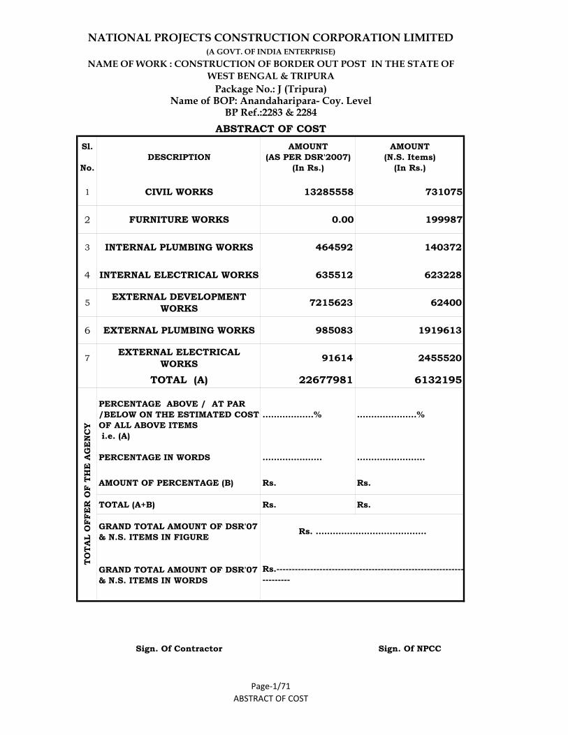
Sl.
No.DESCRIPTION
AMOUNT(AS PER DSR'2007)
(In Rs.)
AMOUNT(N.S. Items)
(In Rs.)
1 CIVIL WORKS 13285558 731075
2 FURNITURE WORKS 0.00 199987
3 INTERNAL PLUMBING WORKS 464592 140372
4 INTERNAL ELECTRICAL WORKS 635512 623228
5EXTERNAL DEVELOPMENT
WORKS 7215623 62400
6 EXTERNAL PLUMBING WORKS 985083 1919613
7EXTERNAL ELECTRICAL
WORKS 91614 2455520
TOTAL (A) 22677981 6132195 PERCENTAGE ABOVE / AT PAR /BELOW ON THE ESTIMATED COST OF ALL ABOVE ITEMS i.e. (A) PERCENTAGE IN WORDS
………………%
…………………
…………………%
……………………
AMOUNT OF PERCENTAGE (B) Rs. Rs.
TOTAL (A+B) Rs. Rs.
GRAND TOTAL AMOUNT OF DSR'07 & N.S. ITEMS IN FIGURE
GRAND TOTAL AMOUNT OF DSR'07 & N.S. ITEMS IN WORDS
Sign. Of Contractor Sign. Of NPCC
ABSTRACT OF COST
Name of BOP: Anandaharipara- Coy. LevelBP Ref.:2283 & 2284
ABSTRACT OF COST
Rs.----------------------------------------------------------------------
TOTA
L O
FFE
R O
F TH
E A
GE
NC
Y
Rs. …………………………………
Page‐1/71
NAME OF WORK : CONSTRUCTION OF BORDER OUT POST IN THE STATE OF WEST BENGAL & TRIPURA
NATIONAL PROJECTS CONSTRUCTION CORPORATION LIMITED
Package No.: J (Tripura)
(A GOVT. OF INDIA ENTERPRISE)