Embed Size (px)
Citation preview
Process Technology
FLUROPIPE®
POLYFLURON®-PTFE linedSteel Pipes and Fittings ASME
Broad Base. Best Solutions.
SGL Group is one of the leading manufacturers of carbon-based products and has the broadest product and technol-ogy portfolio, a global sales network and state-of-the-art production sites in Europe, North America and Asia.
Carbon has unique properties. It is indispensable in the production of steel, aluminum and solar energy systems. Carbon increases the performance of wind turbines and reduces the weight of airplanes, cars and sports equipment.
CCarbon substitutes other materials and contributes to a reduction in CO2 emissions.
Carbon is Future. SGL Group – The Carbon Company.
The Business Unit Process Technology is a premium technology provider for chemical and related industry process systems, equipment and after sales services. Our focus are high-tech materials for demanding chemical applications. With smart and sustainable solutions for an in-creasing number of industry we give proof of our strong innovation culture.
Broad Base
Our range of materials: E graphiteE SiCE PTFEE reactive metalsE steel
Our range of services: E process designE engineeringE project managementE production and assemblyE commissioningE after sales services.
With 9 manufacturing sites in 8 countries and a continually growing worldwide sales and service network, we are always close to our customers.
Process Technology
3
In a business that strongly depends on reliability we never compromise on quality and safety. Our products deliver dependable results; our services are fast and competent. The long-standing loyalty of our customers proves that we keep our promises – on-time, on-spec, on-budget.
Tailor made, innovative solutions and an integrated approach on chemistry, materials, technology and design, ensure outstanding efficiency and improved customer value: higher yields, lower operating cost, lower service and maintenance cost, longer service intervals and less downtimes, and the extended product lifetime sum up to significant lower total cost of ownership and to a higher return on investment for our customers.
In all industries that deal with resource- and energy- consuming processes sustainability is of crucial importance. Based on innovative solutions, more than 60 % of our sales contribute to the saving of resources and energy and to the reduction of greenhouse gases.
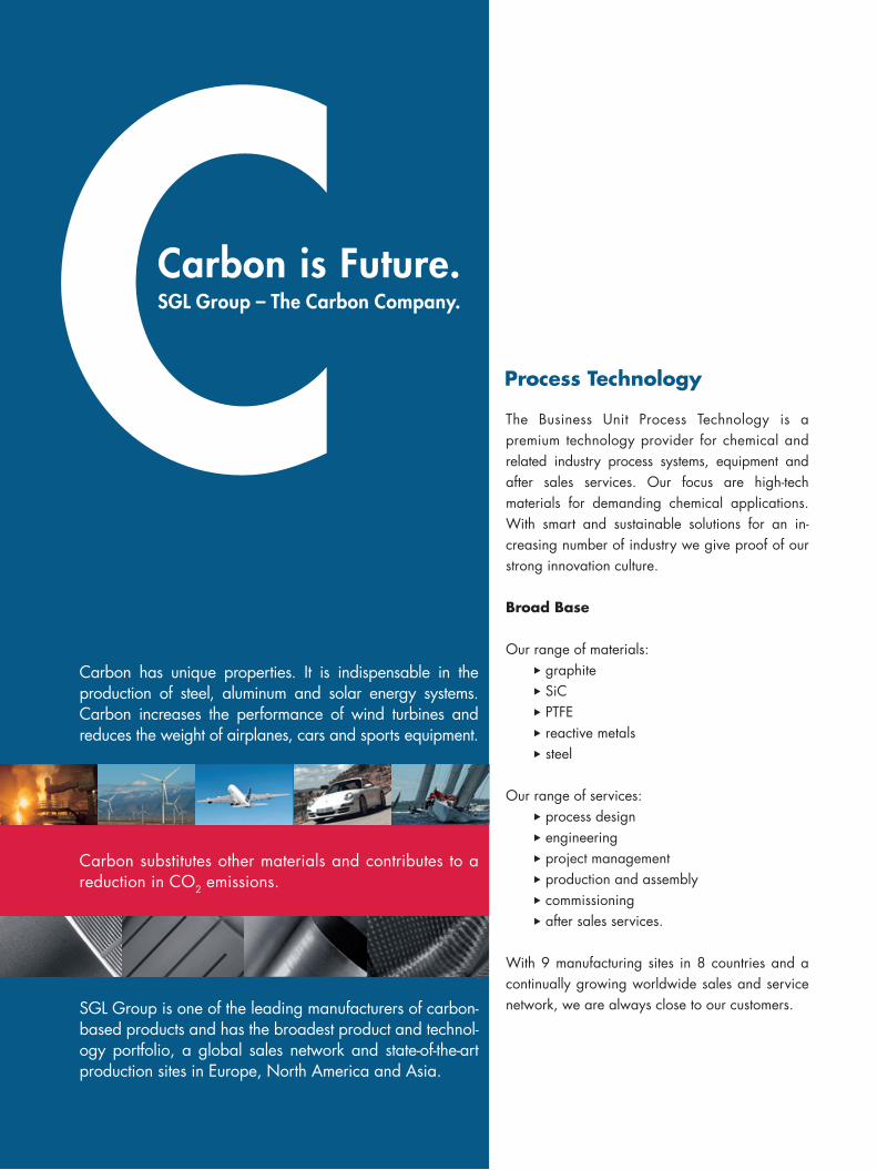
Powered by our Broad Base of competencies, products and services, we offer Best Solutions to our customers. For the Business Unit Process Technology, those solutions are characterized by reliability, efficiency and sustainability.
Contents
Dr. Schnabel - PTFE in the Process Industry 4
Our Range of Pipe Systems 5
Technical Specifications 6
PTFE Lined Pipes 8
PTFE Lined Elbows 10
PTFE Lined Tees 11
PTFE Lined Reducing Tees 12
PTFE Lined Crosses 13
PTFE Lined Reducing Crosses 14
PTFE Lined Instrument Tees 16
PTFE Lined Reducers 17
PTFE Lined Reducing Flanges 18
PTFE and PTFE Lined Spacers 20
PTFE Lined Blind Flanges 22
Quality Management and After Sales Service 23
Process Technology – Our Products 24
ReliaBiliTy. effiCienCy. SuSTainaBiliTy.
Best Solutions
E Reliability
E Efficiency
E Sustainability
4
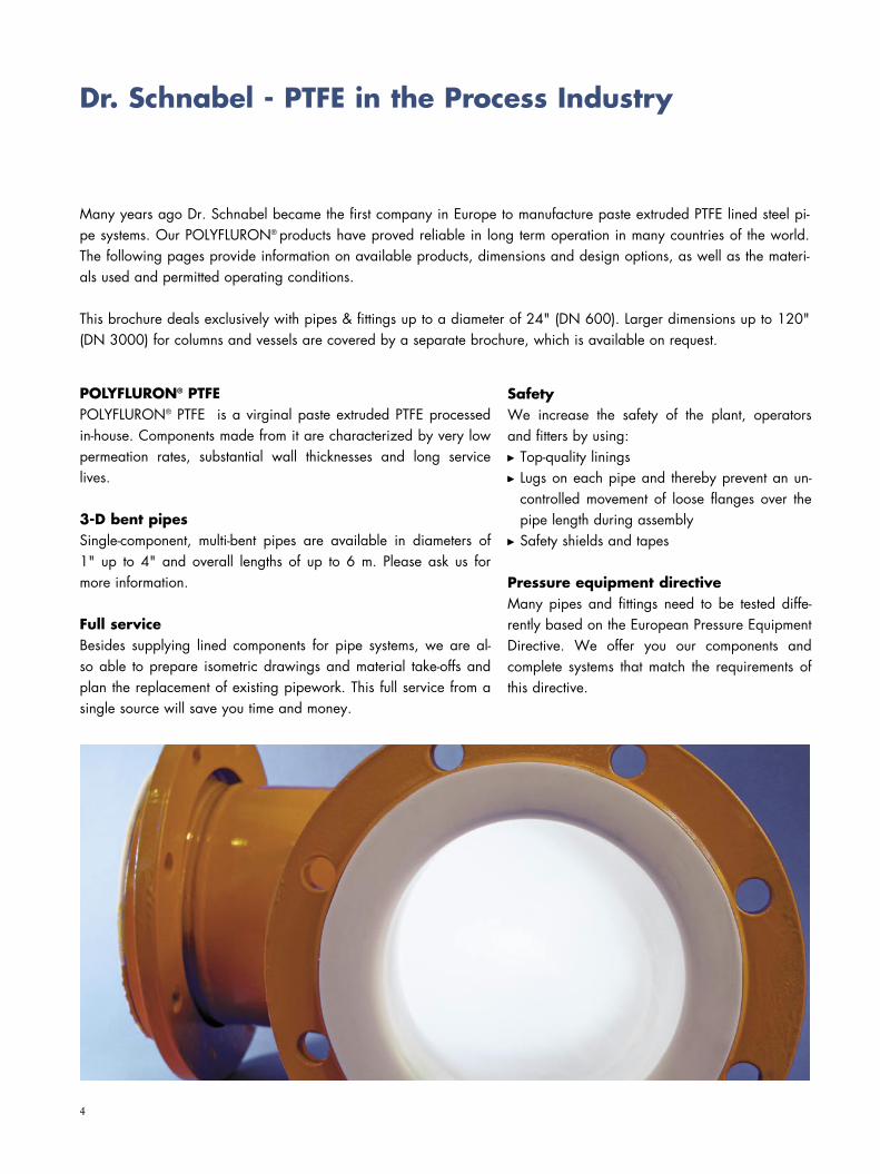
Many years ago Dr. Schnabel became the first company in Europe to manufacture paste extruded PTFE lined steel pi-pe systems. Our POLYFLURON® products have proved reliable in long term operation in many countries of the world. The following pages provide information on available products, dimensions and design options, as well as the materi-als used and permitted operating conditions.
This brochure deals exclusively with pipes & fittings up to a diameter of 24" (DN 600). Larger dimensions up to 120" (DN 3000) for columns and vessels are covered by a separate brochure, which is available on request.
Dr. Schnabel - PTFE in the Process Industry
POLYFLURON® PTFEPOLYFLURON® PTFE is a virginal paste extruded PTFE processed in-house. Components made from it are characterized by very low permeation rates, substantial wall thicknesses and long service lives.
3-D bent pipesSingle-component, multi-bent pipes are available in diameters of 1" up to 4" and overall lengths of up to 6 m. Please ask us for more information.
Full serviceBesides supplying lined components for pipe systems, we are al-so able to prepare isometric drawings and material take-offs and plan the replacement of existing pipework. This full service from a single source will save you time and money.
SafetyWe increase the safety of the plant, operators and fitters by using: Top-quality linings Lugs on each pipe and thereby prevent an un-controlled movement of loose flanges over the pipe length during assembly
Safety shields and tapes
Pressure equipment directiveMany pipes and fittings need to be tested diffe-rently based on the European Pressure Equipment Directive. We offer you our components and complete systems that match the requirements of this directive.
5
More than 50 years experience has allowed us to develop a full range of POLYFLURON® PTFE lined pipe systems. These systems offer the best cost/benefit ratio for our customers‘ particular applications because of the different PTFE lining thicknesses used:
EconomyCorrosion resistant, thin walled lining for minor applications. This kind of lining is used at fairly low temperatures with low-permeation media.
StandardCorrosion resistant and permeation reducing lining for aggressive media processed at moderate pres-sures and temperatures. This product series meets the standards of the chemical industry for paste extruded PTFE linings.
Heavy dutySuitable for long term operation with highly permeable media processed at high pressures and tem-peratures.
Dr. Schnabel’s range of pipe & fittingsFrom our many years experience, we recommend the use of standardized pipe lengths. These reduce inventory costs and allow greater flexibility in assembly.
Our product range includes pipes of the following dimensions:
Nominal diameters: from 1" to 24"Lengths: from 100 mm up to 6100 mm (20 ft.), depending on the nominal diameter
Our Range of Pipe Systems
6
MaterialsThe standards given below are ASME standards. If you require pipes and fit-tings according to ASME standards, please refer to our respective EN/ DIN brochure.
Technical Specifications
Vacuum: Full vacuum (-1 barg) for all dimensions up to 4" and 150 °C. Vacuum-resistant ver-sions for larger dimensions and higher temperatures on request.
Options
Antistatic (conductive) lining for all components Vent hole extensions Stainless steel with PTFE lining 3-D bent pipes Flared steel pipes Insulation clips Earthing lugs
Pipes/Fittings:
Material code
A 106 Gr. B
API 5L Gr. B
A 234 WPB
Flanges: Material code
A 105 (C21)
S235JRG2 (A 570 Gr. 36)
P265 GH (A 515 Gr. 55)
Subject to technical changes
Stainless steel materials are available on request.
Lining: POLYFLURON® PTFE white (virginal paste-extruded PTFE) meeting DIN 2874.
POLYFLURON® PTFE black
(virginal paste-extruded PTFE with graphite content) antistatic, conductive lining meeting DIN 2874.
Field of use
Temperatures: -10° up to +200°C (-263 K up to 473 K)
Pressure load: 10 bar (106 Pa) (150 lbs) Please ask us for information
on higher pressure ratings (e.g. 300 lbs).
7
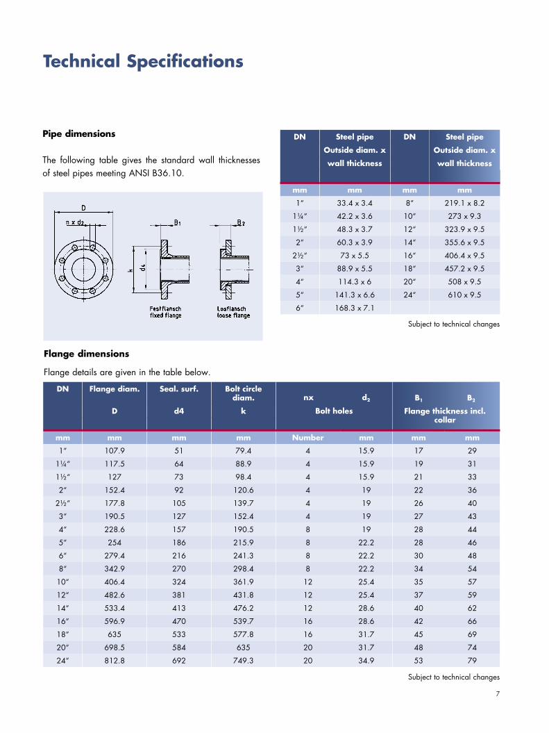
Pipe dimensions
The following table gives the standard wall thicknesses of steel pipes meeting ANSI B36.10.
Flange dimensions
Flange details are given in the table below.
Technical Specifications
DN Flange diam. Seal. surf. Bolt circle diam.
D d4 k B1 B2
mm mm mm mm Number mm mm mm
1“ 107.9 51 79.4 4 15.9 17 29
1¼“ 117.5 64 88.9 4 15.9 19 31
1½“ 127 73 98.4 4 15.9 21 33
2“ 152.4 92 120.6 4 19 22 36
2½“ 177.8 105 139.7 4 19 26 40
3“ 190.5 127 152.4 4 19 27 43
4“ 228.6 157 190.5 8 19 28 44
5“ 254 186 215.9 8 22.2 28 46
6“ 279.4 216 241.3 8 22.2 30 48
8“ 342.9 270 298.4 8 22.2 34 54
10“ 406.4 324 361.9 12 25.4 35 57
12“ 482.6 381 431.8 12 25.4 37 59
14“ 533.4 413 476.2 12 28.6 40 62
16“ 596.9 470 539.7 16 28.6 42 66
18“ 635 533 577.8 16 31.7 45 69
20“ 698.5 584 635 20 31.7 48 74
24“ 812.8 692 749.3 20 34.9 53 79
Bolt holes Flanschdicke inkl. Bund
DN Steel pipe DN Steel pipe
Outside diam. x Outside diam. x
wall thickness wall thickness
mm mm mm mm
1“ 33.4 x 3.4 8“ 219.1 x 8.2
1¼“ 42.2 x 3.6 10“ 273 x 9.3
1½“ 48.3 x 3.7 12“ 323.9 x 9.5
2“ 60.3 x 3.9 14“ 355.6 x 9.5
2½“ 73 x 5.5 16“ 406.4 x 9.5
3“ 88.9 x 5.5 18“ 457.2 x 9.5
4“ 114.3 x 6 20“ 508 x 9.5
5“ 141.3 x 6.6 24“ 610 x 9.5
6“ 168.3 x 7.1
Steel pipe
Outside diam. x
wall thickness
Subject to technical changes
Subject to technical changes
B1 B2
Flange thickness incl. collar
nx d2
8
Order no.
* Please indicate length with order
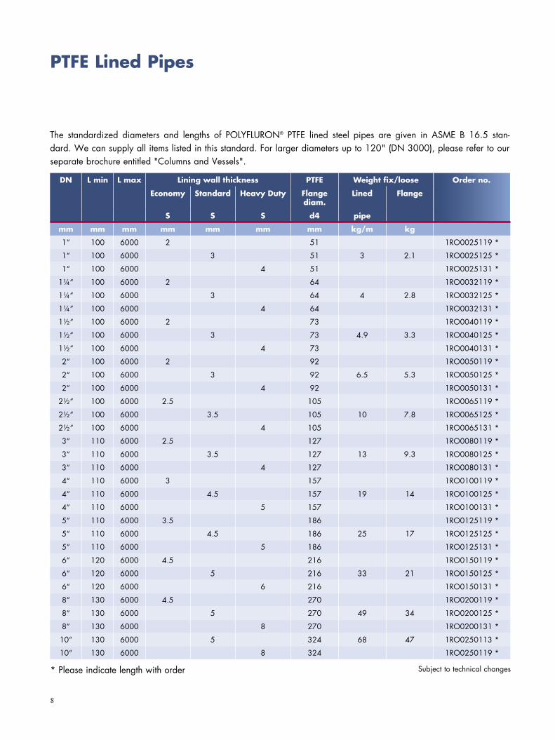
PTFE Lined Pipes
The standardized diameters and lengths of POLYFLURON® PTFE lined steel pipes are given in ASME B 16.5 stan-dard. We can supply all items listed in this standard. For larger diameters up to 120" (DN 3000), please refer to our separate brochure entitled "Columns and Vessels".
DN L min L max Lining wall thickness PTFE Weight fix/loose
Economy Standard Heavy Duty Flange diam.
Lined Flange
S S S d4 pipe
mm mm mm mm mm mm mm kg/m kg
1“ 100 6000 2 51 1RO0025119 *
1“ 100 6000 3 51 3 2.1 1RO0025125 *
1“ 100 6000 4 51 1RO0025131 *
1¼“ 100 6000 2 64 1RO0032119 *
1¼“ 100 6000 3 64 4 2.8 1RO0032125 *
1¼“ 100 6000 4 64 1RO0032131 *
1½“ 100 6000 2 73 1RO0040119 *
1½“ 100 6000 3 73 4.9 3.3 1RO0040125 *
1½“ 100 6000 4 73 1RO0040131 *
2“ 100 6000 2 92 1RO0050119 *
2“ 100 6000 3 92 6.5 5.3 1RO0050125 *
2“ 100 6000 4 92 1RO0050131 *
2½“ 100 6000 2.5 105 1RO0065119 *
2½“ 100 6000 3.5 105 10 7.8 1RO0065125 *
2½“ 100 6000 4 105 1RO0065131 *
3“ 110 6000 2.5 127 1RO0080119 *
3“ 110 6000 3.5 127 13 9.3 1RO0080125 *
3“ 110 6000 4 127 1RO0080131 *
4“ 110 6000 3 157 1RO0100119 *
4“ 110 6000 4.5 157 19 14 1RO0100125 *
4“ 110 6000 5 157 1RO0100131 *
5“ 110 6000 3.5 186 1RO0125119 *
5“ 110 6000 4.5 186 25 17 1RO0125125 *
5“ 110 6000 5 186 1RO0125131 *
6“ 120 6000 4.5 216 1RO0150119 *
6“ 120 6000 5 216 33 21 1RO0150125 *
6“ 120 6000 6 216 1RO0150131 *
8“ 130 6000 4.5 270 1RO0200119 *
8“ 130 6000 5 270 49 34 1RO0200125 *
8“ 130 6000 8 270 1RO0200131 *
10“ 130 6000 5 324 68 47 1RO0250113 *
10“ 130 6000 8 324 1RO0250119 *
Subject to technical changes
9
Order no.
PTFE Lined Pipes
DN L min L max Lining wall thickness PTFE Weight
Economy Standard Heavy Duty Flange diam.
Lined Flange PTFE
S S S d4 pipe
mm mm mm mm mm mm mm kg/m kg
12“ 150 4000 5.5 381 86 71 1RO0300113
12“ 150 4000 8 381 1RO0300119
14“ 150 3500 5.5 413 94 92 1RO0300113
14“ 150 2500 8 413 1RO0300119
16“ 200 2500 5.5 470 109 113 1RO0300113
16“ 200 2500 8 470 1RO0300119
18“ 200 2000 5.5 533 121 128 1RO0300113
18“ 200 2000 8 533 1RO0300119
20“ 250 2000 6 584 136 159 1RO0300113
20“ 250 2000 8 584 1RO0300119
24“ 250 1800 6 692 165 218 1RO0300113
24“ 250 1600 8 692 1RO0300119
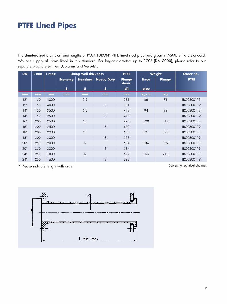
The standardized diameters and lengths of POLYFLURON® PTFE lined steel pipes are given in ASME B 16.5 standard. We can supply all items listed in this standard. For larger diameters up to 120" (DN 3000), please refer to our separate brochure entitled „Columns and Vessels“.
Subject to technical changes* Please indicate length with order
10
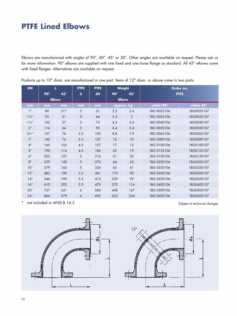
PTFE Lined Elbows
Elbows are manufactured with angles of 90°, 60°, 45° or 30°. Other angles are available on request. Please ask us for more information. 90° elbows are supplied with one fixed and one loose flange as standard. All 45° elbows come with fixed flanges. Alternatives are available on request.
Products up to 10" diam. are manufactured in one part. Items of 12" diam. or above come in two parts.
* not included in ANSI B 16.5
DN L PTFE PTFE Weight
90° 45° S d4 90° 45°
Elbow Elbow
mm mm mm mm mm approx. kg white 90° white 45°
1“ 89 51* 3 51 2.5 2.4 1BG 0025106 1BG0025107
1¼“ 95 51 3 64 3.3 3 1BG 0032106 1BG0032107
1½“ 102 57 3 73 4.2 3.6 1BG 0040106 1BG0040107
2“ 114 64 3 92 6.4 5.4 1BG 0050106 1BG0050107
2½“ 127 76 3.5 105 8.8 7.9 1BG 0065106 1BG0065107
3“ 140 76 3.5 127 12 10 1BG 0080106 1BG0080107
4“ 165 102 4.5 157 17 15 1BG 0100106 1BG0100107
5“ 190 114 4.5 186 22 19 1BG 0125106 1BG0125107
6“ 203 127 5 216 31 22 1BG 0150106 1BG0150107
8“ 229 140 5 270 44 35 1BG 0200106 1BG0200107
10“ 279 165 5 324 65 61 1BG 0250106 1BG0250107
12“ 483 190 5.5 381 175 90 1BG 0300106 1BG0300107
14“ 546 190 5.5 413 239 99 1BG 0350106 1BG0350107
16“ 610 203 5.5 470 275 116 1BG 0400106 1BG0400107
20“ 737 241 6 584 448 167 1BG 0500106 1BG0500107
24“ 864 279 6 692 625 234 1BG 0600106 1BG0600107
Order no.
PTFE
Subject to technical changes
12"
11
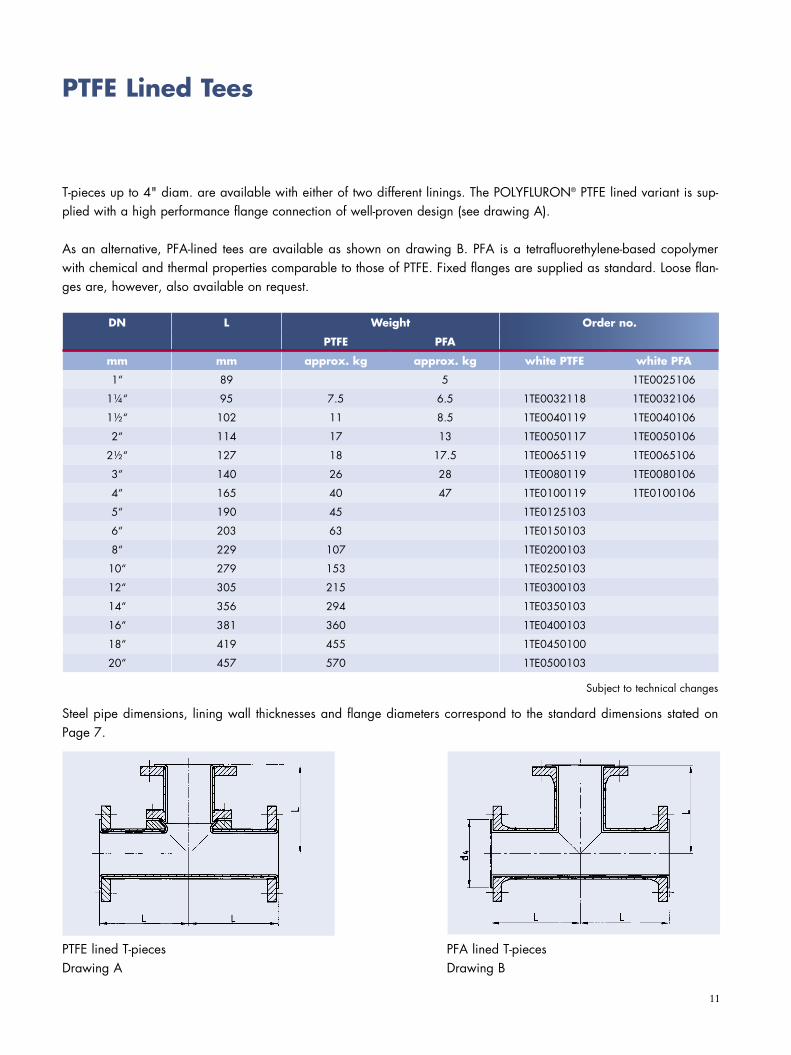
PTFE Lined Tees
T-pieces up to 4" diam. are available with either of two different linings. The POLYFLURON® PTFE lined variant is sup-plied with a high performance flange connection of well-proven design (see drawing A).
As an alternative, PFA-lined tees are available as shown on drawing B. PFA is a tetrafluorethylene-based copolymer with chemical and thermal properties comparable to those of PTFE. Fixed flanges are supplied as standard. Loose flan-ges are, however, also available on request.
DN L Weight Best.-Nr.
PTFE PFA
mm mm approx. kg approx. kg white PTFE white PFA
1“ 89 5 1TE0025106
1¼“ 95 7.5 6.5 1TE0032118 1TE0032106
1½“ 102 11 8.5 1TE0040119 1TE0040106
2“ 114 17 13 1TE0050117 1TE0050106
2½“ 127 18 17.5 1TE0065119 1TE0065106
3“ 140 26 28 1TE0080119 1TE0080106
4“ 165 40 47 1TE0100119 1TE0100106
5“ 190 45 1TE0125103
6“ 203 63 1TE0150103
8“ 229 107 1TE0200103
10“ 279 153 1TE0250103
12“ 305 215 1TE0300103
14“ 356 294 1TE0350103
16“ 381 360 1TE0400103
18“ 419 455 1TE0450100
20“ 457 570 1TE0500103
Steel pipe dimensions, lining wall thicknesses and flange diameters correspond to the standard dimensions stated on Page 7.
PTFE lined T-piecesDrawing A
PFA lined T-piecesDrawing B
Order no.
Subject to technical changes
12
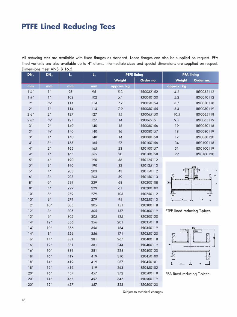
PTFE Lined Reducing Tees
All reducing tees are available with fixed flanges as standard. Loose flanges can also be supplied on request. PFA lined variants are also available up to 4" diam.. Intermediate sizes and special dimensions are supplied on request. Dimensions meet ANSI B 16.5.
DN1 DN2 L1 L2 PTFE lining Best.-Nr.GewichtWeight Order no.
mm mm mm mm approx. kg approx. kg
1¼“ 1“ 95 95 5.3 1RT0032152 4.2 1RT0032112
1¼“ 1“ 102 102 6.1 1RT0040130 5.2 1RT0040112
2“ 1½“ 114 114 9.7 1RT0050154 8.7 1RT0050118
2“ 1“ 114 114 7.9 1RT0050155 8.4 1RT0050119
2½“ 2“ 127 127 15 1RT0065150 10.5 1RT0065118
2½“ 1½“ 127 127 14 1RT0065151 9.5 1RT0065119
3“ 2“ 140 140 18 1RT0080156 19 1RT0080118
3“ 1½“ 140 140 16 1RT0080157 18 1RT0080119
3“ 1“ 140 140 14 1RT0080158 17 1RT0080120
4“ 3“ 165 165 27 1RT0100156 34 1RT0100118
4“ 2“ 165 165 23 1RT0100157 31 1RT0100119
4“ 1“ 165 165 20 1RT0100158 29 1RT0100120
5“ 4“ 190 190 36 1RT0125112
5“ 3“ 190 190 32 1RT0125113
6“ 4“ 203 203 43 1RT0150112
6“ 3“ 203 203 39 1RT0150113
8“ 6“ 229 229 68 1RT0200108
8“ 4“ 229 229 61 1RT0200109
10“ 8“ 279 279 105 1RT0250112
10“ 6“ 279 279 94 1RT0250113
12“ 10“ 305 305 151 1RT0300118
12“ 8“ 305 305 137 1RT0300119
12“ 6“ 305 305 125 1RT0300120
14“ 12“ 356 356 201 1RT0350118
14“ 10“ 356 356 184 1RT0350119
14“ 8“ 356 356 171 1RT0350120
16“ 14“ 381 381 267 1RT0400118
16“ 12“ 381 381 244 1RT0400119
16“ 10“ 381 381 228 1RT0400120
18“ 16“ 419 419 310 1RT0450100
18“ 14“ 419 419 287 1RT0450101
18“ 12“ 419 419 263 1RT0450102
20“ 16“ 457 457 372 1RT0500118
20“ 14“ 457 457 347 1RT0500119
20“ 12“ 457 457 323 1RT0500120
Subject to technical changes
PFA lining
Weight Order no.
PTFE lined reducing T-piece
PFA lined reducing T-piece
13
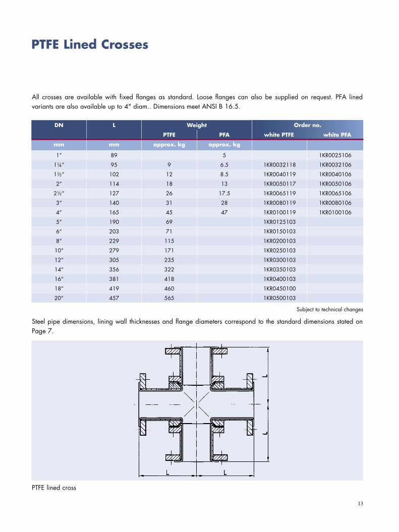
Steel pipe dimensions, lining wall thicknesses and flange diameters correspond to the standard dimensions stated on Page 7.
PTFE Lined Crosses
All crosses are available with fixed flanges as standard. Loose flanges can also be supplied on request. PFA lined variants are also available up to 4" diam.. Dimensions meet ANSI B 16.5.
PTFE lined cross
DN L Weight Order number
PTFE PFA PTFE PFA
mm mm approx. kg approx. kg
1“ 89 5 1KR0025106
1¼“ 95 9 6.5 1KR0032118 1KR0032106
1½“ 102 12 8.5 1KR0040119 1KR0040106
2“ 114 18 13 1KR0050117 1KR0050106
2½“ 127 26 17.5 1KR0065119 1KR0065106
3“ 140 31 28 1KR0080119 1KR0080106
4“ 165 45 47 1KR0100119 1KR0100106
5“ 190 69 1KR0125103
6“ 203 71 1KR0150103
8“ 229 115 1KR0200103
10“ 279 171 1KR0250103
12“ 305 235 1KR0300103
14“ 356 322 1KR0350103
16“ 381 418 1KR0400103
18“ 419 460 1KR0450100
20“ 457 565 1KR0500103
Subject to technical changes
Order no.
white PTFE white PFA

14
Steel pipe dimensions, lining wall thicknesses and flange diameters correspond to the stan-dard dimensions stated on Page 7.
PTFE Lined Reducing Crosses
All crosses are available with fixed flanges as standard. Loose flanges can also be supplied on request. Dimensions meet ANSI B 16.5.
* nicht in DIN 2848 enthalten
DN1 DN2 L1 L2 Weight Order no.
PTFE PFA
mm mm mm mm ap-prox.
kg
ap-prox.
kg
white PTFE white PFA
1¼“ 1“ 95 95 8.5 4.5 1KR0032182 1KR032142
1½“ 1“ 102 102 9.3 5.2 1KR0040162 1KR040144
2“ 1½“ 114 114 14 8.7 1KR0050178 1KR0050142
2“ 1“ 114 114 11 8.4 1KR0050179 1KR0050143
2½“ 2“ 127 127 18 12 1KR0065182 1KR0065150
2½“ 1½“ 127 127 16 11 1KR0065183 1KR0065151
3“ 2“ 140 140 22 19 1KR0080189 1KR0080151
3“ 1½“ 140 140 19 18 1KR0080190 1KR0080152
3“ 1“ 140 140 16 17 1KR0080191 1KR0080153
4“ 3“ 165 165 31 34 1KR0100189 1KR0100151
4“ 2“ 165 165 26 31 1KR0100190 1KR0032142
4“ 1“ 165 165 22 29 1KR0100191 1KR0100153
5“ 4“ 190 190 42 1KR0125128
5“ 3“ 190 190 33 1KR0125129
6“ 4“ 203 203 49 1KR0150128
6“ 3“ 203 203 43 1KR0150129
8“ 6“ 229 229 76 1KR0200124
8“ 4“ 229 229 62 1KR0200125
10“ 8“ 279 279 165 1KR0250128
10“ 6“ 279 279 108 1KR0250129
12“ 10“ 305 305 187 1KR0300134
12“ 8“ 305 305 165 1KR0300135
12“ 6“ 305 305 142 1KR0300136
14“ 12“ 356 356 259 1KR0350134
14“ 10“ 356 356 231 1KR0350135
14“ 8“ 356 365 212 1KR0350136
16“ 14“ 381 381 323 1KR0400134
16“ 12“ 381 381 288 1KR0400135
16“ 10“ 381 381 261 1KR0400136
18“ 16“ 419 419 415 1KR0450104
18“ 14“ 419 419 381 1KR0450105
18“ 12“ 419 419 347 1KR0450106
20“ 16“ 457 457 459 1KR0500134
20“ 14“ 457 457 417 1KR0500135
20“ 12“ 457 457 355 1KR0500136
Subject to technical changes
Order no.
15
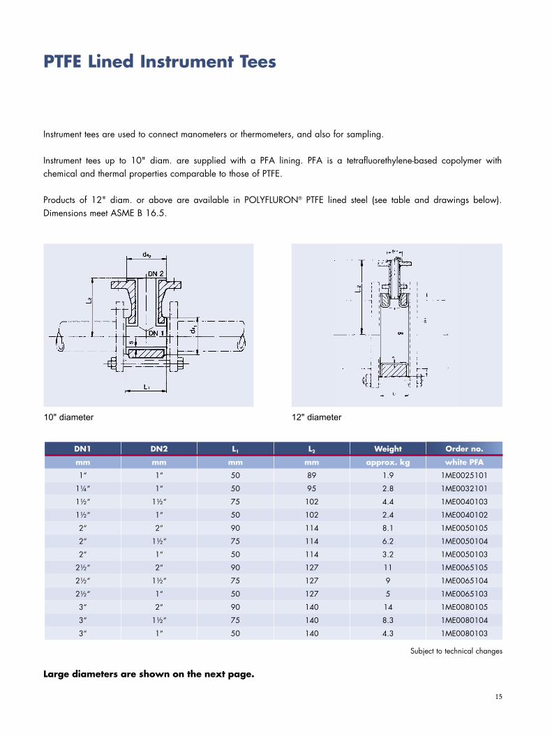
PTFE Lined Instrument Tees
Instrument tees are used to connect manometers or thermometers, and also for sampling.
Instrument tees up to 10" diam. are supplied with a PFA lining. PFA is a tetrafluorethylene-based copolymer with chemical and thermal properties comparable to those of PTFE.
Products of 12" diam. or above are available in POLYFLURON® PTFE lined steel (see table and drawings below). Dimensions meet ASME B 16.5.
10" diameter 12" diameter
DN1 DN2 L1 L2 Weight Order no.
mm mm mm mm approx. kg white PFA
1“ 1“ 50 89 1.9 1ME0025101
1¼“ 1“ 50 95 2.8 1ME0032101
1½“ 1½“ 75 102 4.4 1ME0040103
1½“ 1“ 50 102 2.4 1ME0040102
2“ 2“ 90 114 8.1 1ME0050105
2“ 1½“ 75 114 6.2 1ME0050104
2“ 1“ 50 114 3.2 1ME0050103
2½“ 2“ 90 127 11 1ME0065105
2½“ 1½“ 75 127 9 1ME0065104
2½“ 1“ 50 127 5 1ME0065103
3“ 2“ 90 140 14 1ME0080105
3“ 1½“ 75 140 8.3 1ME0080104
3“ 1“ 50 140 4.3 1ME0080103
Subject to technical changes
Order no.
Large diameters are shown on the next page.
16
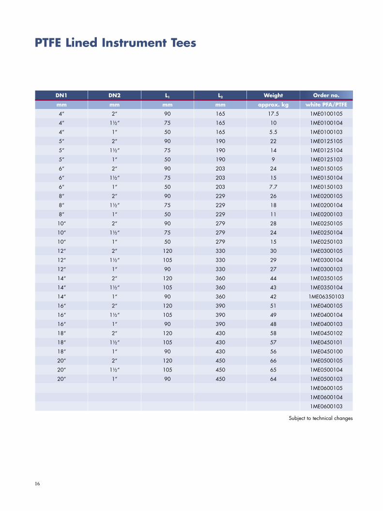
PTFE Lined Instrument Tees
DN1 DN2 L1 L2 Weight Order no.
mm mm mm mm approx. kg white PFA/PTFE
4“ 2“ 90 165 17.5 1ME0100105
4“ 1½“ 75 165 10 1ME0100104
4“ 1“ 50 165 5.5 1ME0100103
5“ 2“ 90 190 22 1ME0125105
5“ 1½“ 75 190 14 1ME0125104
5“ 1“ 50 190 9 1ME0125103
6“ 2“ 90 203 24 1ME0150105
6“ 1½“ 75 203 15 1ME0150104
6“ 1“ 50 203 7.7 1ME0150103
8“ 2“ 90 229 26 1ME0200105
8“ 1½“ 75 229 18 1ME0200104
8“ 1“ 50 229 11 1ME0200103
10“ 2“ 90 279 28 1ME0250105
10“ 1½“ 75 279 24 1ME0250104
10“ 1“ 50 279 15 1ME0250103
12“ 2“ 120 330 30 1ME0300105
12“ 1½“ 105 330 29 1ME0300104
12“ 1“ 90 330 27 1ME0300103
14“ 2“ 120 360 44 1ME0350105
14“ 1½“ 105 360 43 1ME0350104
14“ 1“ 90 360 42 1ME06350103
16“ 2“ 120 390 51 1ME0400105
16“ 1½“ 105 390 49 1ME0400104
16“ 1“ 90 390 48 1ME0400103
18“ 2“ 120 430 58 1ME0450102
18“ 1½“ 105 430 57 1ME0450101
18“ 1“ 90 430 56 1ME0450100
20“ 2“ 120 450 66 1ME0500105
20“ 1½“ 105 450 65 1ME0500104
20“ 1“ 90 450 64 1ME0500103
1ME0600105
1ME0600104
1ME0600103
Subject to technical changes
Order no.
17
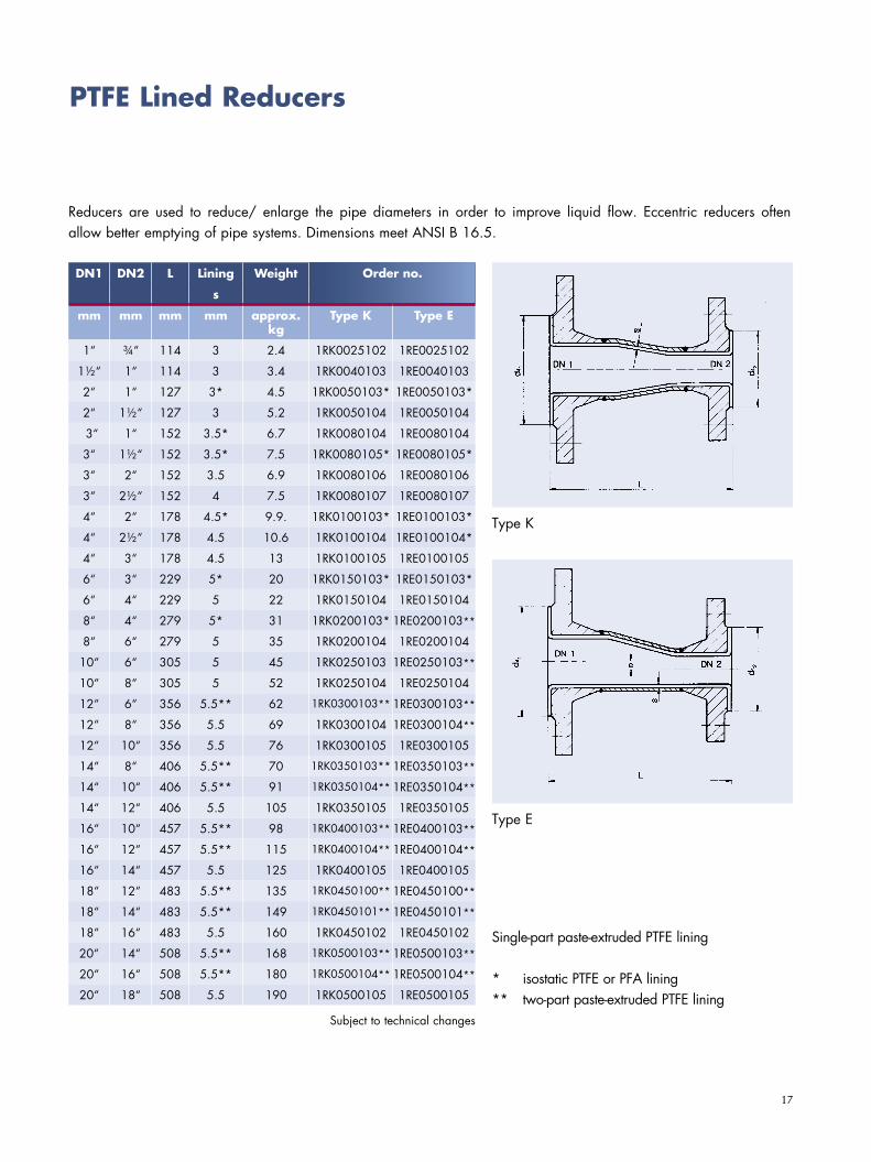
PTFE Lined Reducers
Reducers are used to reduce/ enlarge the pipe diameters in order to improve liquid flow. Eccentric reducers often allow better emptying of pipe systems. Dimensions meet ANSI B 16.5.
Single-part paste-extruded PTFE lining
* isostatic PTFE or PFA lining** two-part paste-extruded PTFE lining
DN1 DN2 L Lining Weight Best.-Nr.
s
mm mm mm mm approx. kg
Type K Type E
1“ ¾“ 114 3 2.4 1RK0025102 1RE0025102
1½“ 1“ 114 3 3.4 1RK0040103 1RE0040103
2“ 1“ 127 3* 4.5 1RK0050103* 1RE0050103*
2“ 1½“ 127 3 5.2 1RK0050104 1RE0050104
3“ 1“ 152 3.5* 6.7 1RK0080104 1RE0080104
3“ 1½“ 152 3.5* 7.5 1RK0080105* 1RE0080105*
3“ 2“ 152 3.5 6.9 1RK0080106 1RE0080106
3“ 2½“ 152 4 7.5 1RK0080107 1RE0080107
4“ 2“ 178 4.5* 9.9. 1RK0100103* 1RE0100103*
4“ 2½“ 178 4.5 10.6 1RK0100104 1RE0100104*
4“ 3“ 178 4.5 13 1RK0100105 1RE0100105
6“ 3“ 229 5* 20 1RK0150103* 1RE0150103*
6“ 4“ 229 5 22 1RK0150104 1RE0150104
8“ 4“ 279 5* 31 1RK0200103* 1RE0200103**
8“ 6“ 279 5 35 1RK0200104 1RE0200104
10“ 6“ 305 5 45 1RK0250103 1RE0250103**
10“ 8“ 305 5 52 1RK0250104 1RE0250104
12“ 6“ 356 5.5** 62 1RK0300103** 1RE0300103**
12“ 8“ 356 5.5 69 1RK0300104 1RE0300104**
12“ 10“ 356 5.5 76 1RK0300105 1RE0300105
14“ 8“ 406 5.5** 70 1RK0350103** 1RE0350103**
14“ 10“ 406 5.5** 91 1RK0350104** 1RE0350104**
14“ 12“ 406 5.5 105 1RK0350105 1RE0350105
16“ 10“ 457 5.5** 98 1RK0400103** 1RE0400103**
16“ 12“ 457 5.5** 115 1RK0400104** 1RE0400104**
16“ 14“ 457 5.5 125 1RK0400105 1RE0400105
18“ 12“ 483 5.5** 135 1RK0450100** 1RE0450100**
18“ 14“ 483 5.5** 149 1RK0450101** 1RE0450101**
18“ 16“ 483 5.5 160 1RK0450102 1RE0450102
20“ 14“ 508 5.5** 168 1RK0500103** 1RE0500103**
20“ 16“ 508 5.5** 180 1RK0500104** 1RE0500104**
20“ 18“ 508 5.5 190 1RK0500105 1RE0500105
Type K
Type E
Order no.
Subject to technical changes
18
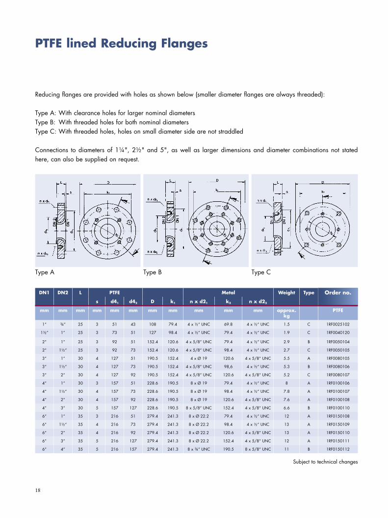
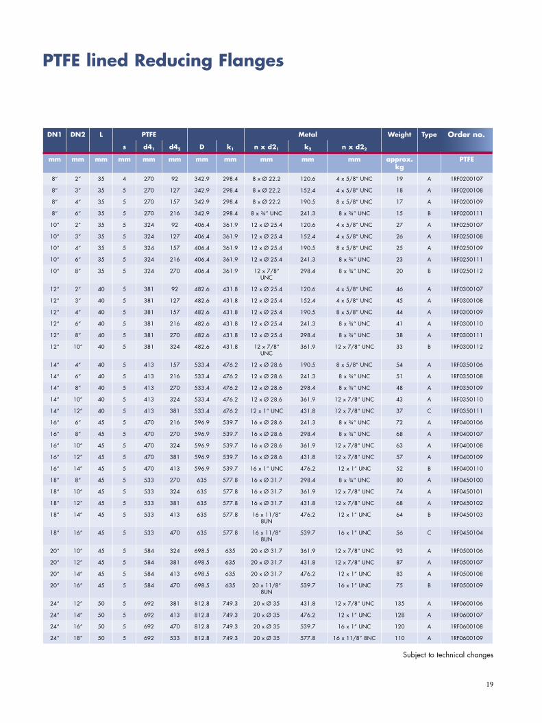
PTFE lined Reducing Flanges
Reducing flanges are provided with holes as shown below (smaller diameter flanges are always threaded):
Type A: With clearance holes for larger nominal diametersType B: With threaded holes for both nominal diametersType C: With threaded holes, holes on small diameter side are not straddled
Connections to diameters of 1¼", 2½" and 5", as well as larger dimensions and diameter combinations not stated here, can also be supplied on request.
Type A Type B Type C
DN1 DN2 L PTFE Metal Weight Type Best.-Nr.
s d41 d42 D k1 n x d21 k2 n x d22
mm mm mm mm mm mm mm mm mm mm mm approx. kg
PTFE
1“ ¾“ 25 3 51 43 108 79.4 4 x ½“ UNC 69.8 4 x ½“ UNC 1.5 C 1RF0025102
1½“ 1“ 25 3 73 51 127 98.4 4 x ½“ UNC 79.4 4 x ½“ UNC 1.9 C 1RF0040120
2“ 1“ 25 3 92 51 152.4 120.6 4 x 5/8“ UNC 79.4 4 x ½“ UNC 2.9 B 1RF0050104
2“ 1½“ 25 3 92 73 152.4 120.6 4 x 5/8“ UNC 98.4 4 x ½“ UNC 2.7 C 1RF0050105
3“ 1“ 30 4 127 51 190.5 152.4 4 x Ø 19 120.6 4 x 5/8“ UNC 5.5 A 1RF0080105
3“ 1½“ 30 4 127 73 190.5 152.4 4 x 5/8“ UNC 98,6 4 x ½“ UNC 5.3 B 1RF0080106
3“ 2“ 30 4 127 92 190.5 152.4 4 x 5/8“ UNC 120.6 4 x 5/8“ UNC 5.2 C 1RF0080107
4“ 1“ 30 3 157 51 228.6 190.5 8 x Ø 19 79.4 4 x ½“ UNC 8 A 1RF0100106
4“ 1½“ 30 4 157 73 228.6 190.5 8 x Ø 19 98.4 4 x ½“ UNC 7.8 A 1RF0100107
4“ 2“ 30 4 157 92 228.6 190.5 8 x Ø 19 120.6 4 x 5/8“ UNC 7.6 A 1RF0100108
4“ 3“ 30 5 157 127 228.6 190.5 8 x 5/8“ UNC 152.4 4 x 5/8“ UNC 6.6 B 1RF0100110
6“ 1“ 35 3 216 51 279.4 241.3 8 x Ø 22.2 79.4 4 x ½“ UNC 12 A 1RF0150108
6“ 1½“ 35 4 216 73 279.4 241.3 8 x Ø 22.2 98.4 4 x ½“ UNC 13 A 1RF0150109
6“ 2“ 35 4 216 92 279.4 241.3 8 x Ø 22.2 120.6 4 x 5/8“ UNC 13 A 1RF0150110
6“ 3“ 35 5 216 127 279.4 241.3 8 x Ø 22.2 152.4 4 x 5/8“ UNC 12 A 1RF0150111
6“ 4“ 35 5 216 157 279.4 241.3 8 x ¾“ UNC 190.5 8 x 5/8“ UNC 11 B 1RF0150112
Subject to technical changes
Order no.
19
DN1 DN2 L PTFE Metal Weight Type Best.-Nr.
s d41 d42 D k1 n x d21 k2 n x d22
mm mm mm mm mm mm mm mm mm mm mm approx. kg
PTFE
8“ 2“ 35 4 270 92 342.9 298.4 8 x Ø 22.2 120.6 4 x 5/8“ UNC 19 A 1RF0200107
8“ 3“ 35 5 270 127 342.9 298.4 8 x Ø 22.2 152.4 4 x 5/8“ UNC 18 A 1RF0200108
8“ 4“ 35 5 270 157 342.9 298.4 8 x Ø 22.2 190.5 8 x 5/8“ UNC 17 A 1RF0200109
8“ 6“ 35 5 270 216 342.9 298.4 8 x ¾“ UNC 241.3 8 x ¾“ UNC 15 B 1RF0200111
10“ 2“ 35 5 324 92 406.4 361.9 12 x Ø 25.4 120.6 4 x 5/8“ UNC 27 A 1RF0250107
10“ 3“ 35 5 324 127 406.4 361.9 12 x Ø 25.4 152.4 4 x 5/8“ UNC 26 A 1RF0250108
10“ 4“ 35 5 324 157 406.4 361.9 12 x Ø 25.4 190.5 8 x 5/8“ UNC 25 A 1RF0250109
10“ 6“ 35 5 324 216 406.4 361.9 12 x Ø 25.4 241.3 8 x ¾“ UNC 23 A 1RF0250111
10“ 8“ 35 5 324 270 406.4 361.9 12 x 7/8“ UNC
298.4 8 x ¾“ UNC 20 B 1RF0250112
12“ 2“ 40 5 381 92 482.6 431.8 12 x Ø 25.4 120.6 4 x 5/8“ UNC 46 A 1RF0300107
12“ 3“ 40 5 381 127 482.6 431.8 12 x Ø 25.4 152.4 4 x 5/8“ UNC 45 A 1RF0300108
12“ 4“ 40 5 381 157 482.6 431.8 12 x Ø 25.4 190.5 8 x 5/8“ UNC 44 A 1RF0300109
12“ 6“ 40 5 381 216 482.6 431.8 12 x Ø 25.4 241.3 8 x ¾“ UNC 41 A 1RF0300110
12“ 8“ 40 5 381 270 482.6 431.8 12 x Ø 25.4 298.4 8 x ¾“ UNC 38 A 1RF0300111
12“ 10“ 40 5 381 324 482.6 431.8 12 x 7/8“ UNC
361.9 12 x 7/8“ UNC 33 B 1RF0300112
14“ 4“ 40 5 413 157 533.4 476.2 12 x Ø 28.6 190.5 8 x 5/8“ UNC 54 A 1RF0350106
14“ 6“ 40 5 413 216 533.4 476.2 12 x Ø 28.6 241.3 8 x ¾“ UNC 51 A 1RF0350108
14“ 8“ 40 5 413 270 533.4 476.2 12 x Ø 28.6 298.4 8 x ¾“ UNC 48 A 1RF0350109
14“ 10“ 40 5 413 324 533.4 476.2 12 x Ø 28.6 361.9 12 x 7/8“ UNC 43 A 1RF0350110
14“ 12“ 40 5 413 381 533.4 476.2 12 x 1“ UNC 431.8 12 x 7/8“ UNC 37 C 1RF0350111
16“ 6“ 45 5 470 216 596.9 539.7 16 x Ø 28.6 241.3 8 x ¾“ UNC 72 A 1RF0400106
16“ 8“ 45 5 470 270 596.9 539.7 16 x Ø 28.6 298.4 8 x ¾“ UNC 68 A 1RF0400107
16“ 10“ 45 5 470 324 596.9 539.7 16 x Ø 28.6 361.9 12 x 7/8“ UNC 63 A 1RF0400108
16“ 12“ 45 5 470 381 596.9 539.7 16 x Ø 28.6 431.8 12 x 7/8“ UNC 57 A 1RF0400109
16“ 14“ 45 5 470 413 596.9 539.7 16 x 1“ UNC 476.2 12 x 1“ UNC 52 B 1RF0400110
18“ 8“ 45 5 533 270 635 577.8 16 x Ø 31.7 298.4 8 x ¾“ UNC 80 A 1RF0450100
18“ 10“ 45 5 533 324 635 577.8 16 x Ø 31.7 361.9 12 x 7/8“ UNC 74 A 1RF0450101
18“ 12“ 45 5 533 381 635 577.8 16 x Ø 31.7 431.8 12 x 7/8“ UNC 68 A 1RF0450102
18“ 14“ 45 5 533 413 635 577.8 16 x 11/8“ 8UN
476.2 12 x 1“ UNC 64 B 1RF0450103
18“ 16“ 45 5 533 470 635 577.8 16 x 11/8“ 8UN
539.7 16 x 1“ UNC 56 C 1RF0450104
20“ 10“ 45 5 584 324 698.5 635 20 x Ø 31.7 361.9 12 x 7/8“ UNC 93 A 1RF0500106
20“ 12“ 45 5 584 381 698.5 635 20 x Ø 31.7 431.8 12 x 7/8“ UNC 87 A 1RF0500107
20“ 14“ 45 5 584 413 698.5 635 20 x Ø 31.7 476.2 12 x 1“ UNC 83 A 1RF0500108
20“ 16“ 45 5 584 470 698.5 635 20 x 11/8“ 8UN
539.7 16 x 1“ UNC 75 B 1RF0500109
24“ 12“ 50 5 692 381 812.8 749.3 20 x Ø 35 431.8 12 x 7/8“ UNC 135 A 1RF0600106
24“ 14“ 50 5 692 413 812.8 749.3 20 x Ø 35 476.2 12 x 1“ UNC 128 A 1RF0600107
24“ 16“ 50 5 692 470 812.8 749.3 20 x Ø 35 539.7 16 x 1“ UNC 120 A 1RF0600108
24“ 18“ 50 5 692 533 812.8 749.3 20 x Ø 35 577.8 16 x 11/8“ 8NC 110 A 1RF0600109
Order no.
Subject to technical changes
PTFE lined Reducing Flanges
20
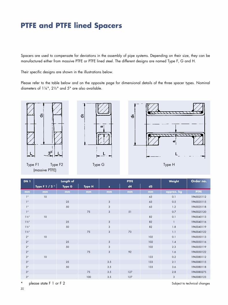
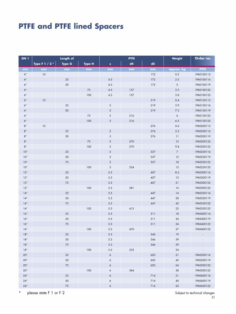
PTFE and PTFE lined Spacers
Spacers are used to compensate for deviations in the assembly of pipe systems. Depending on their size, they can be manufactured either from massive PTFE or PTFE lined steel. The different designs are named Type F, G and H.
Their specific designs are shown in the illustrations below.
Please refer to the table below and on the opposite page for dimensional details of the three spacer types. Nominal diameters of 1¼", 2½" and 5" are also available.
Type F1 Type F2(massive PTFE)
Type G Type H
* please state F 1 or F 2 Subject to technical changes
DN 1 Length of PTFE Weight Best.-Nr.
Type F 1 / 2 * Type G Type H s d4 d5
mm mm mm mm mm mm mm approx. kg PTFE
1“ 10 63 0.1 1PA0025112
1“ 25 3 63 0.5 1PA0025115
1“ 50 3 63 1.2 1PA0025118
1“ 75 3 51 0.7 1PA0025120
1½“ 10 82 0.1 1PA0040113
1½“ 25 3 82 1 1PA0040116
1½“ 50 3 82 1.8 1PA0040119
1½“ 75 3 73 1.1 1PA0040122
2“ 10 102 0.1 1PA0050113
2“ 25 3 102 1.4 1PA0050116
2“ 50 3 102 2.3 1PA0050119
2“ 75 3 92 1.6 1PA0050122
3“ 10 133 0.2 1PA0080112
3“ 25 3.5 133 2.1 1PA0080115
3“ 50 3.5 133 3.6 1PA0080118
3“ 75 3.5 127 2.8 1PA0080275
3“ 100 3.5 127 3 1PA0080123
Order no.
21
DN 1 Length of PTFE Weight Best.-Nr.
Type F 1 / 2 * Type G Type H s d4 d5
mm mm mm mm mm mm mm approx. kg PTFE
4“ 10 172 0.2 1PA0100113
4“ 25 4.5 172 2.5 1PA0100116
4“ 50 4.5 172 5 1PA0100119
4“ 75 4.5 157 3.5 1PA0100122
4“ 100 4.5 157 3.8 1PA0100125
6“ 10 219 0.4 1PA0150113
6“ 25 5 219 3.9 1PA0150116
6“ 50 5 219 7.2 1PA0150119
6“ 75 5 216 6 1PA0150122
6“ 100 5 216 6.5 1PA0150125
8“ 10 276 0.6 1PA0200113
8“ 25 5 276 5.3 1PA0200116
8“ 50 5 276 11 1PA0200119
8“ 75 5 270 15 1PA0200122
8“ 100 5 270 9.8 1PA0200125
10“ 25 5 337 7 1PA0250116
10“ 50 5 337 13 1PA0250119
10“ 75 5 337 18 1PA0250122
10“ 100 5 324 13 1PA0250125
12“ 25 5.5 407 8.2 1PA0300116
12“ 50 5.5 407 15 1PA0300119
12“ 75 5.5 407 21 1PA0300122
12“ 100 5.5 381 16 1PA0300125
14“ 25 5.5 447 14 1PA0350116
14“ 50 5.5 447 28 1PA0350119
14“ 75 5.5 447 42 1PA0350122
14“ 100 5.5 413 22 1PA0350125
16“ 25 5.5 511 18 1PA0400116
16“ 50 5.5 511 36 1PA0400119
16“ 75 5.5 511 54 1PA0400122
16“ 100 5.5 470 27 1PA0400125
18“ 25 5.5 546 19 -
18“ 50 5.5 546 39 -
18“ 75 5.5 546 59 -
18“ 100 5.5 533 34 -
20“ 25 6 603 21 1PA0500116
20“ 50 6 603 42 1PA0500119
20“ 75 6 603 64 1PA0500122
20“ 100 6 584 38 1PA0500125
24“ 25 6 714 21 1PA0600116
24“ 50 6 714 40 1PA0600119
24“ 75 6 714 65 1PA0600122
Order no.
PTFE and PTFE lined Spacers
* please state F 1 or F 2 Subject to technical changes
22
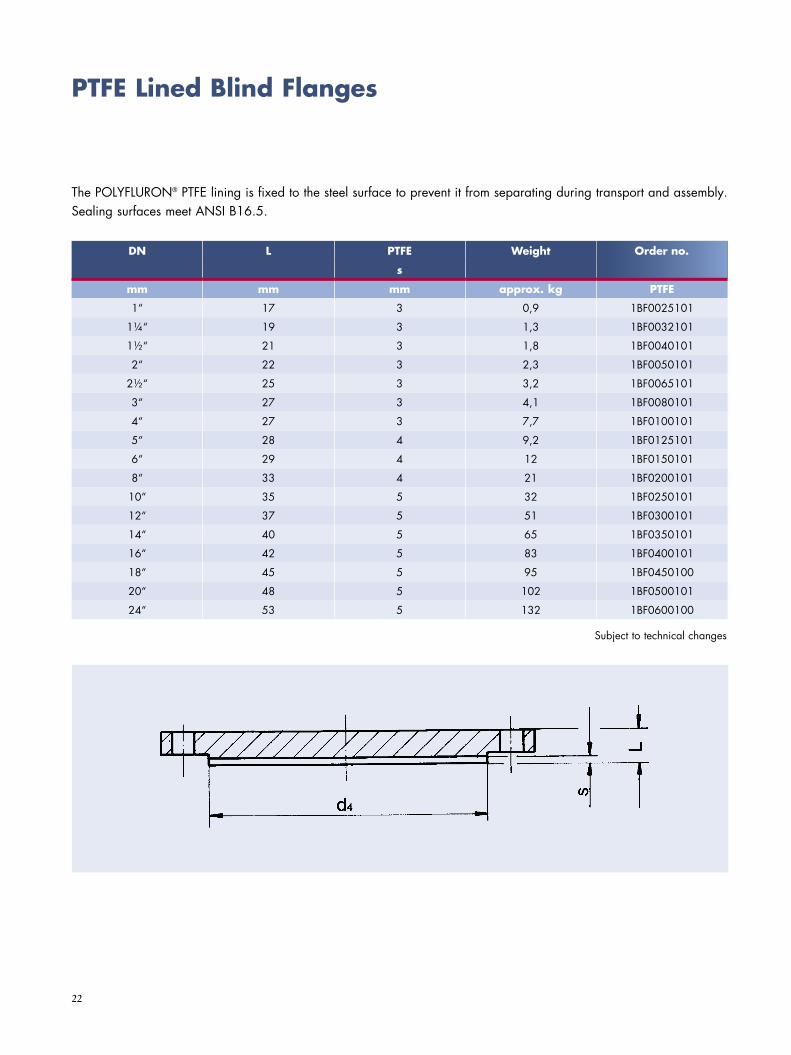
PTFE Lined Blind Flanges
DN L PTFE Weight Best. Nr.
s
mm mm mm approx. kg PTFE
1“ 17 3 0,9 1BF0025101
1¼“ 19 3 1,3 1BF0032101
1½“ 21 3 1,8 1BF0040101
2“ 22 3 2,3 1BF0050101
2½“ 25 3 3,2 1BF0065101
3“ 27 3 4,1 1BF0080101
4“ 27 3 7,7 1BF0100101
5“ 28 4 9,2 1BF0125101
6“ 29 4 12 1BF0150101
8“ 33 4 21 1BF0200101
10“ 35 5 32 1BF0250101
12“ 37 5 51 1BF0300101
14“ 40 5 65 1BF0350101
16“ 42 5 83 1BF0400101
18“ 45 5 95 1BF0450100
20“ 48 5 102 1BF0500101
24“ 53 5 132 1BF0600100
The POLYFLURON® PTFE lining is fixed to the steel surface to prevent it from separating during transport and assembly. Sealing surfaces meet ANSI B16.5.
Order no.
Subject to technical changes

23
Quality Management
Continuous quality assurance is an integral part of the SGL Group corporate philosophy. Our quality management system is certified in accordance with ISO 9001:2008. In order to guarantee consis tently high quality to our customers, we work according to a key performance indicator orientated quality management system.
Depending on specifications we are able to meet specific requirements like the Pressure Equipment Directive 97/23/EC Annex III, Module H/H1, AD 2000 Merkblatt N2 as well as ASME “U” Stamp, Section VIII, Part UIG.
Quality Management and After Sales Service
After Sales Services – Anytime and Everywhere
We take care of our products during the entire operational lifetime. We aim to provide the best customer service anytime and everywhere.
E Maintenance – genuine spare parts supply, failure analysis, repair, field service
E Fast emergency supportE Start-up assistanceE Consulting for continuous improvement
Our service specialists as well as our service centers work in a global network to support you best.
24
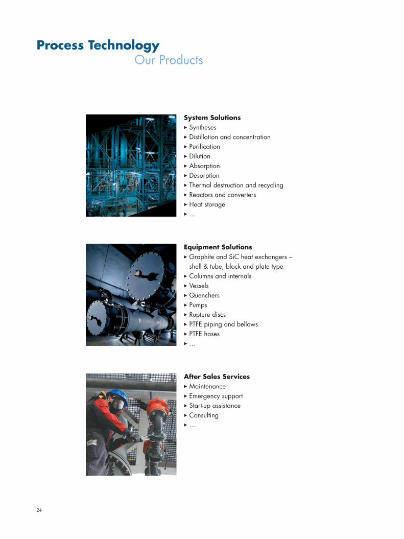
System SolutionsE Syntheses E Distillation and concentrationE PurificationE DilutionE AbsorptionE DesorptionE Thermal destruction and recyclingE Reactors and convertersE Heat storageE ...
After Sales ServicesE MaintenanceE Emergency supportE Start-up assistanceE ConsultingE ...
Equipment SolutionsE Graphite and SiC heat exchangers –
shell & tube, block and plate typeE Columns and internals E VesselsE QuenchersE PumpsE Rupture discsE PTFE piping and bellowsE PTFE hoses E ...
Process Technology Our Products
Central and East Europe
SGL CARBON GmbHWerner-von-Siemens-Straße 1886405 Meitingen/GermanyPhone +49 8271 83-1564Fax +49 8271 [email protected]
South Europe, Middle East, Africa
SGL CARBON Technic S.A.S.18, Avenue Marcel Cachin38407 Saint Martin d‘Heres/FrancePhone +33 4 7625 9600Fax +33 4 7625 [email protected]
Americas
SGL CARBON Technic, LLC 21945 Drake Road44149 Strongsville, Ohio/USAPhone +1 440 572-3600Fax +1 440 [email protected]
Process Technology
SGL CARBON GmbH
Söhnleinstraße 865201 Wiesbaden/Germanywww.sgl-processtechnology.com
www.sglgroup.com
® registered trademark of SGL Group companies 04 2012/0 1NÄ Printed in Germany
The data contained herein represent the current state of our product knowledge and are intended to provide general information on our products and their application spectra. In view of the variety and large number of application possibilities, these data should be regarded merely as general information that gives no guarantee of any specific properties and/or suitability of those products for any particular application. Consequently, when ordering a product, please contact us for specific information on the properties required for the application concerned. On request, our technical service will supply a profile of characteristics for your specific application requirements without delay.
Regional Sales & Service Center
Asia, Oceania
SGL CARBON Far East Ltd. Shanghai 1208, Shanghai Oriental Plaza31 Wujiang Road/ChinaPhone +86 21 5211 0333Fax +86 21 5211 0085 [email protected]
India
SGL CARBON India Pvt. Ltd.Plot No. E-100, MIDC RanjangaonVillage: Karegaon, Taluka: ShirurDist. Pune - 412 220/IndiaPhone +91 21 386 122-14