Embed Size (px)
Citation preview
PDHonline Course K125 (2 PDH)
Creating the Plant Pipe Code
2012
Instructor: William N. Weaver , P.E.
PDH Online | PDH Center5272 Meadow Estates Drive
Fairfax, VA 22030-6658Phone & Fax: 703-988-0088
www.PDHonline.orgwww.PDHcenter.com
An Approved Continuing Education Provider
www.PDHcenter.com PDH Course K125 www.PDHonline.org
Creating the Plant Pipe Code
W.N. Weaver, PE 1. INTRODUCTION Pipes codes are used to standardize piping practices in a facility, to ensure each fluid is conveyed in the appropriate materials, to control piping costs and to ensure plant safety. There are multiple pipe codes in use in the various industries involved with pipe; some are listed below: ASME BPE For the pharmaceutical industry ASME B31 Pressure piping B31.1 Power Piping B31.2 Fuel Gas Piping B31.3 Process Piping B31.4 Liquid Hydrocarbon Transmission Pipelines B31.5 Refrigerant Piping B31.8 Natural Gas Transmission Pipelines B31.9 Building Services API Piping in the Petroleum Industries ASHRAE Refrigerant piping AWWA American Water Works Associations water piping Local governments Potable water Local governments Waste water Local governments Storm water Hydraulic systems Tubing and piping for high pressure fluid power systems NFPA Sprinkler piping NFPA Extinguishing agent piping Creating proper pipe codes for your facility is generally a combined effort between engineering, operations and maintenance. Where available piping, corrosion and welding engineers should be included in the design group. It is not necessary to start the creation process with a blank sheet of paper; starting from an existing national code simplifies the process and gives everyone a view of what the finished product should look like and contain. Before we go further let us see why we even need a pipe code. It’s generally easier to produce an appropriate document if we understand the reason we need the document in the first place. 2. WHY HAVE A PIPE CODE? Most process plants have pipe codes in place which are used for bidding, construction, new design planning, and repairs. Several points will indicate some of the benefits of internal pipe codes.
©2008 W.N. Weaver, PE Page 2 of 19
www.PDHcenter.com PDH Course K125 www.PDHonline.org
• Pressure safety • Ensures proper wall thickness, connection types and gasketing to hold the
required pressure • Consistency of connection types
• Ensures proper joint efficiencies, gaskets and flange types to maintain design conditions
• Consistency in materials of construction for specific fluids • Ensures corrosion is controlled
• Pre use testing of new and or repaired pipe lines • Provides standardized testing for all pipe codes
• Proper gasket materials selection • Ensures gaskets reflect corrosion research and pressure requirements
• Proper structural support for pipe lines • Provides pipe span details for each pipe size and schedule
• Control of fugitive emissions from the piping system • Reduces fugitive emissions by reducing leaks from improperly selected
connections • Reduction or elimination of contamination of raw materials and products
• Reduces corrosion contamination by ensuring proper materials for each fluid • Reduction in leakage which results in money saved in raw materials and finished
product, reduces environmental problems, reduces fire and injury hazards • Maximizes control of leakage by ensuring proper gaskets and joint types
Some cities and counties have had individual disaster experiences, which have caused them to institute pipe codes for specific materials within their political jurisdictions. These may well be more restrictive than the recognized national codes. Certain areas of the country exposed to hazards specific to their locations have added requirements to piping systems which, are more restrictive than those in other areas. As an example you would expect California to have more requirements for pipe supports on hazardous materials than non earthquake prone areas. Individual facility pipe codes can generally be more restrictive than nationally recognized codes. Great care and consultation with the company legal and insurance departments are called for if the developed pipe code is less restrictive than the national standard. 3. WHY CREATE A PLANT PIPE CODE? Why not just use an existing nationally recognized code? Let’s look at various materials in pipes and see if we can find justification for facility specific pipe codes. Compressed Air Over the years I have seen or installed compressed air piping systems using the following types of pipe: Carbon steel, schedules 40 and 80 Stainless steel, schedules 5, 10, 20 and 40 using 304 and 316
©2008 W.N. Weaver, PE Page 3 of 19
Copper, K, L and M
www.PDHcenter.com PDH Course K125 www.PDHonline.org
Copper pipe in .065 inch wall and schedule 40 Galvanized steel PVC Aluminum Which is the correct one for your facility? Common to almost all facilities is Potable Water (City Water and Well Water in some companies) Types of pipe encountered in use Carbon steel Stainless steel, schedules 5, 10, 20 and 40 using 304 and 316 Copper, K, L and M Galvanized steel PVC, schedules 40 and 80 CPVC Glass Fiber glass Cast iron Cement lined steel Rubber lined steel From these two examples it is obvious there are multiple codes for some fluids. More importantly each of these codes does the job and is considered as a correct application for the fluid by someone. 4. WHAT DOES THE PIPE CODE ACCOMPLISH? A fully developed pipe code provides the following: • Allowable design pressures • Allowable temperatures • Acceptable selection of materials of construction • Pipe wall schedule verses fluid pressure • Acceptable valve types • Connections to be used for the pipe: welded, flanged, threaded, etc. • Branch connection table • Bolting for flanges • Acceptable gasket materials • Reinforcing requirements (reinforcing pads) • Surface protection required • Acceptable insulation • Heat Tracing • Heat or cooling jacketing • Allowable unsupported spans
©2008 W.N. Weaver, PE Page 4 of 19
• Accepted methods of fabrication of the pipe

www.PDHcenter.com PDH Course K125 www.PDHonline.org
It is not necessary that all pipe codes contain all of the above items, later we’ll see how to determine what is needed for your facility and how the facility can benefit by using a home grown pipe code. 5. PIPING CONNECTION OPTIONS Invariably pipes must be connected to other pipes, valves, instruments and equipment. How these connections are made is critical to the longevity of the piping system and the cost of maintenance. Additionally these connections frequently limit the allowable pressure of the system. Piping connections need to offer some or all of the following characteristics: • Pressure tightness • Fluid tightness • Material compatibility • Temperature capability • Corrosion resistance • Connection rigidity • Connection longevity • Relative ease of use Commonly used piping connection methods include the following: 1. Socket welded 2. Butt welded 3. Threaded 4. Flanged 5. Grooved 6. Soldered 7. Brazed 8. Flare fittings 9. Silver soldered 10. Compression fittings 11. Adhesives 12. “O” ring fittings 13. Sheet metal couplings (ex. Morris Coupling) 1, 2, 3, 4, and 5 are common in metal piping systems. 6, 7, 8, 9, and 10 are common in metallic tubing systems 10, 11 and 12 are generally useful in plastic piping systems 12 and 13 are generally used in duct conveying systems The acceptable connection systems for each pipe code should be included in the codes you create.
©2008 W.N. Weaver, PE Page 5 of 19
www.PDHcenter.com PDH Course K125 www.PDHonline.org
6. POINTS TO CONSIDER Most pipes have several mechanical properties to be considered when being selected for a specific task. Let’s look at the two characteristics most often considered; Pressure Rating and Allowable Temperature.
PRESSURE Pipes have four pressures of importance. • MAXIMUM ALLOWABLE PRESSURE. Established by a nationally recognized
organization such as ASME, insurance, local political jurisdiction, or calculations based on materials of construction structural properties.
• DESIGN PRESSURE. Established by the facility pipe code, perhaps a nationally recognized code or the facility insurance carrier. Usually an arbitrarily selected value which meets facility needs.
• OPERATING PRESSURE. Established by operational needs, the facility pipe code, or a nationally recognized code. Another arbitrarily selected value which meets facility needs.
• BURST PRESSURE. Established by the manufacturer or a national code such as ASME / ASTM by actual testing or by calculations based on the metal alloy and temperature.
TEMPERATURE We also have several temperatures to consider. • DESIGN TEMPERATURE. Established by the facility pipe code, perhaps a
nationally recognized code or the facility insurance carrier. Usually an arbitrarily selected value which meets facility needs.
• OPERATING TEMPERATURE. Established by operational needs, the facility pipe code, or a nationally recognized code. Another arbitrarily selected value which meets facility needs.
• MAXIMUM USABLE TEMPERATURE. Established by the manufacturer or a national code such as ASME / ASTM by actual testing or by calculations based on the metal alloy.
©2008 W.N. Weaver, PE Page 6 of 19
Note that metal pipe (actually almost all pipe) has a temperature / pressure curve which means that Design Pressure and Design Temperature must be considered together. As a general rule metal pipe will withstand less pressure at higher temperature and in some cases at lower temperatures as well. This tells us we must know the maximum expected Operating Temperature before we can actually select a suitable material of construction
www.PDHcenter.com PDH Course K125 www.PDHonline.org
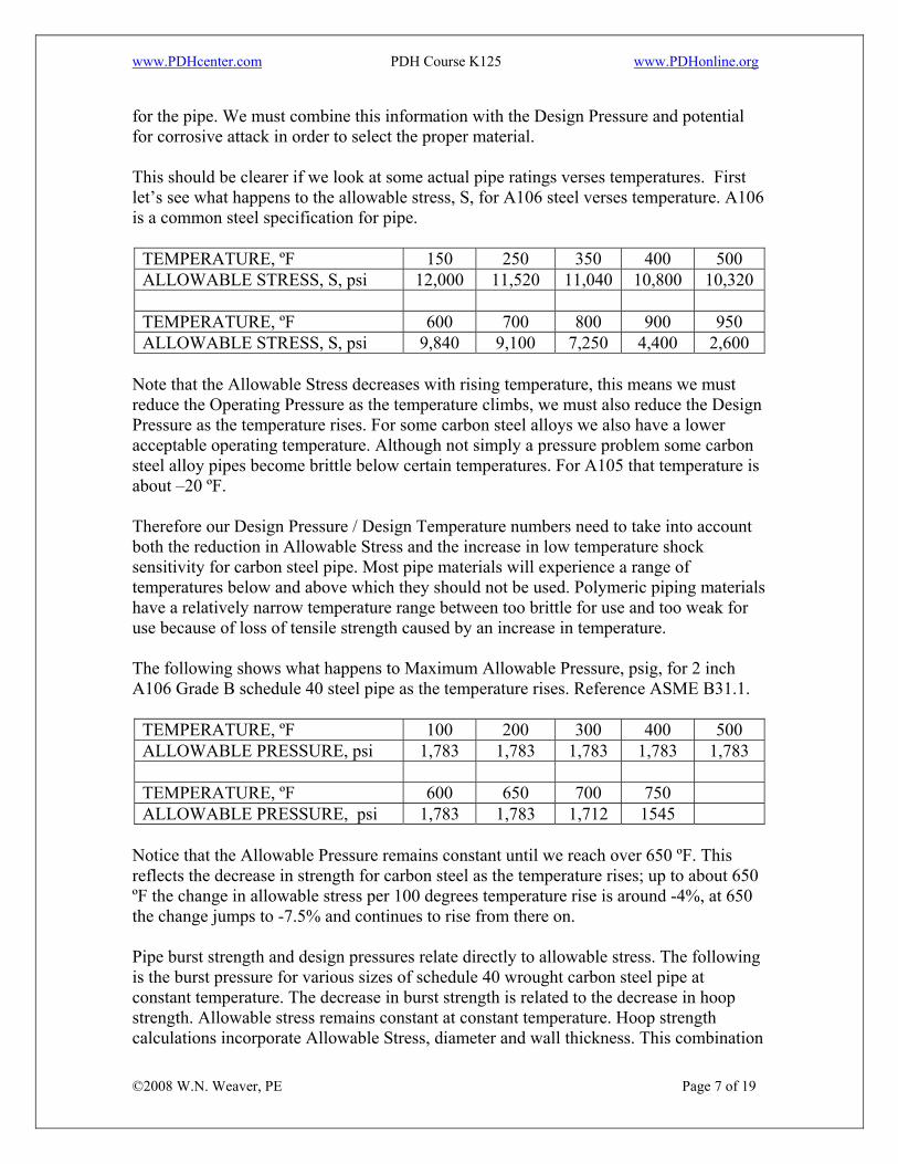
for the pipe. We must combine this information with the Design Pressure and potential for corrosive attack in order to select the proper material. This should be clearer if we look at some actual pipe ratings verses temperatures. First let’s see what happens to the allowable stress, S, for A106 steel verses temperature. A106 is a common steel specification for pipe.
TEMPERATURE, ºF 150 250 350 400 500 ALLOWABLE STRESS, S, psi 12,000 11,520 11,040 10,800 10,320 TEMPERATURE, ºF 600 700 800 900 950 ALLOWABLE STRESS, S, psi 9,840 9,100 7,250 4,400 2,600
Note that the Allowable Stress decreases with rising temperature, this means we must reduce the Operating Pressure as the temperature climbs, we must also reduce the Design Pressure as the temperature rises. For some carbon steel alloys we also have a lower acceptable operating temperature. Although not simply a pressure problem some carbon steel alloy pipes become brittle below certain temperatures. For A105 that temperature is about –20 ºF. Therefore our Design Pressure / Design Temperature numbers need to take into account both the reduction in Allowable Stress and the increase in low temperature shock sensitivity for carbon steel pipe. Most pipe materials will experience a range of temperatures below and above which they should not be used. Polymeric piping materials have a relatively narrow temperature range between too brittle for use and too weak for use because of loss of tensile strength caused by an increase in temperature. The following shows what happens to Maximum Allowable Pressure, psig, for 2 inch A106 Grade B schedule 40 steel pipe as the temperature rises. Reference ASME B31.1.
TEMPERATURE, ºF 100 200 300 400 500 ALLOWABLE PRESSURE, psi 1,783 1,783 1,783 1,783 1,783 TEMPERATURE, ºF 600 650 700 750 ALLOWABLE PRESSURE, psi 1,783 1,783 1,712 1545
Notice that the Allowable Pressure remains constant until we reach over 650 ºF. This reflects the decrease in strength for carbon steel as the temperature rises; up to about 650 ºF the change in allowable stress per 100 degrees temperature rise is around -4%, at 650 the change jumps to -7.5% and continues to rise from there on.
©2008 W.N. Weaver, PE Page 7 of 19
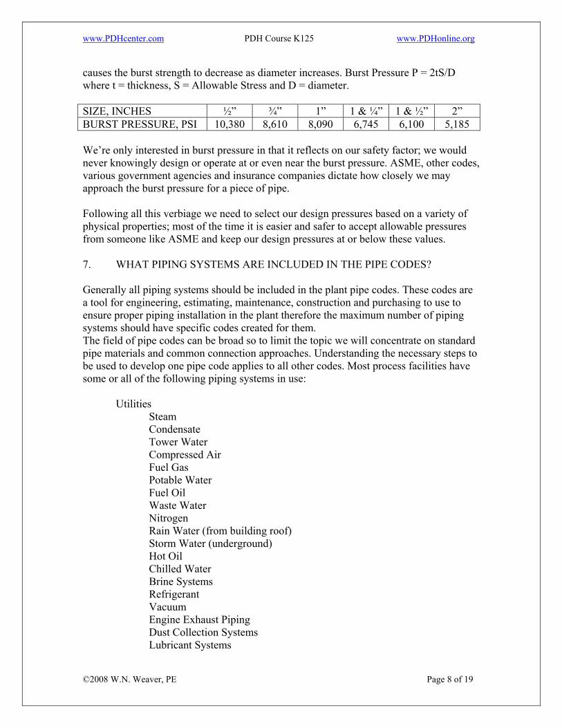
Pipe burst strength and design pressures relate directly to allowable stress. The following is the burst pressure for various sizes of schedule 40 wrought carbon steel pipe at constant temperature. The decrease in burst strength is related to the decrease in hoop strength. Allowable stress remains constant at constant temperature. Hoop strength calculations incorporate Allowable Stress, diameter and wall thickness. This combination
www.PDHcenter.com PDH Course K125 www.PDHonline.org
causes the burst strength to decrease as diameter increases. Burst Pressure P = 2tS/D where t = thickness, S = Allowable Stress and D = diameter. SIZE, INCHES ½” ¾” 1” 1 & ¼” 1 & ½” 2” BURST PRESSURE, PSI 10,380 8,610 8,090 6,745 6,100 5,185 We’re only interested in burst pressure in that it reflects on our safety factor; we would never knowingly design or operate at or even near the burst pressure. ASME, other codes, various government agencies and insurance companies dictate how closely we may approach the burst pressure for a piece of pipe. Following all this verbiage we need to select our design pressures based on a variety of physical properties; most of the time it is easier and safer to accept allowable pressures from someone like ASME and keep our design pressures at or below these values. 7. WHAT PIPING SYSTEMS ARE INCLUDED IN THE PIPE CODES? Generally all piping systems should be included in the plant pipe codes. These codes are a tool for engineering, estimating, maintenance, construction and purchasing to use to ensure proper piping installation in the plant therefore the maximum number of piping systems should have specific codes created for them. The field of pipe codes can be broad so to limit the topic we will concentrate on standard pipe materials and common connection approaches. Understanding the necessary steps to be used to develop one pipe code applies to all other codes. Most process facilities have some or all of the following piping systems in use: Utilities Steam Condensate
Tower Water Compressed Air
Fuel Gas Potable Water
Fuel Oil Waste Water
Nitrogen Rain Water (from building roof) Storm Water (underground) Hot Oil Chilled Water Brine Systems Refrigerant Vacuum Engine Exhaust Piping Dust Collection Systems
©2008 W.N. Weaver, PE Page 8 of 19
Lubricant Systems
www.PDHcenter.com PDH Course K125 www.PDHonline.org
Process Liquid Raw Materials (solvents, acids, caustics, other chemicals) Finished Products Heat Traced Pipe Jacketed Pipe (heating or cooling) Pneumatic Conveying Systems Safety Systems Sprinkler Piping Safety Shower / Eyewash Stations Pressure Relief Device Discharge Piping Fire Lines 8. DEVELOPING THE CODE A complete pipe code will contain significant information on the requirements the pipes must meet during operation. Or stated differently, the pipe codes give us the acceptable ranges of temperatures and pressures under which our facility has agreed a particular type of pipe can be used. Notice that the authority in this case is “our facility”; it is no less an authority than ASME or a local code and a violation of this code puts facility insurance coverage in jeopardy. In the event of a failure of a piping system which results in lawsuits the violation of a “plant standard” pipe code generally can be expected to have negative effects in court. The first activities in developing the code require we establish three process related criteria: • Corrosion Resistance For example this process requirement determines if we can
use carbon steel pipe or need a stainless alloy to resist the effects of the fluids.
• Operating Temperature This criteria separates polymeric materials from most metallic piping materials and is the expected normal or maximum temperature the system will experience.
• Operating Pressure This criteria with the first two provides the data necessary to determine the required wall thickness for the pipe and is the expected normal or maximum pressure the system will see.
Corrosion resistance can be determined from a variety of corrosion tables (Perry’s Handbook, pipe manufacturer’s web sites, etc.), facility chemists and historical data from the maintenance department. In addition to normal corrosion concerns maintenance records, industry experience and insurance records may indicate problems with threaded connections with some raw materials, utilities or finished products.
©2008 W.N. Weaver, PE Page 9 of 19
Design Temperature is selected based on Operating Temperature plus some tolerance to allow for system deviation from normal operating conditions. Determining the tolerance required can be complicated and needs to incorporate consideration of items like the following:
www.PDHcenter.com PDH Course K125 www.PDHonline.org
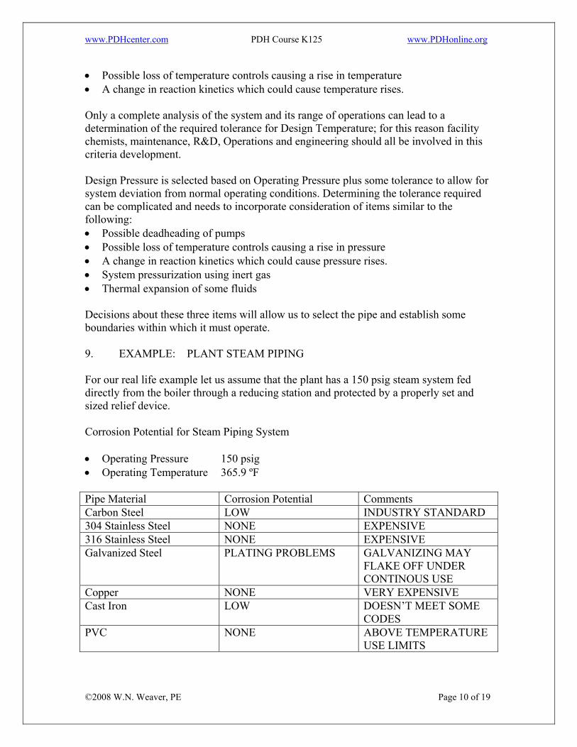
• Possible loss of temperature controls causing a rise in temperature • A change in reaction kinetics which could cause temperature rises. Only a complete analysis of the system and its range of operations can lead to a determination of the required tolerance for Design Temperature; for this reason facility chemists, maintenance, R&D, Operations and engineering should all be involved in this criteria development. Design Pressure is selected based on Operating Pressure plus some tolerance to allow for system deviation from normal operating conditions. Determining the tolerance required can be complicated and needs to incorporate consideration of items similar to the following: • Possible deadheading of pumps • Possible loss of temperature controls causing a rise in pressure • A change in reaction kinetics which could cause pressure rises. • System pressurization using inert gas • Thermal expansion of some fluids Decisions about these three items will allow us to select the pipe and establish some boundaries within which it must operate. 9. EXAMPLE: PLANT STEAM PIPING For our real life example let us assume that the plant has a 150 psig steam system fed directly from the boiler through a reducing station and protected by a properly set and sized relief device. Corrosion Potential for Steam Piping System • Operating Pressure 150 psig • Operating Temperature 365.9 ºF Pipe Material Corrosion Potential Comments Carbon Steel LOW INDUSTRY STANDARD 304 Stainless Steel NONE EXPENSIVE 316 Stainless Steel NONE EXPENSIVE Galvanized Steel PLATING PROBLEMS GALVANIZING MAY
FLAKE OFF UNDER CONTINOUS USE
Copper NONE VERY EXPENSIVE Cast Iron LOW DOESN’T MEET SOME
CODES PVC NONE ABOVE TEMPERATURE
USE LIMITS
©2008 W.N. Weaver, PE Page 10 of 19
www.PDHcenter.com PDH Course K125 www.PDHonline.org
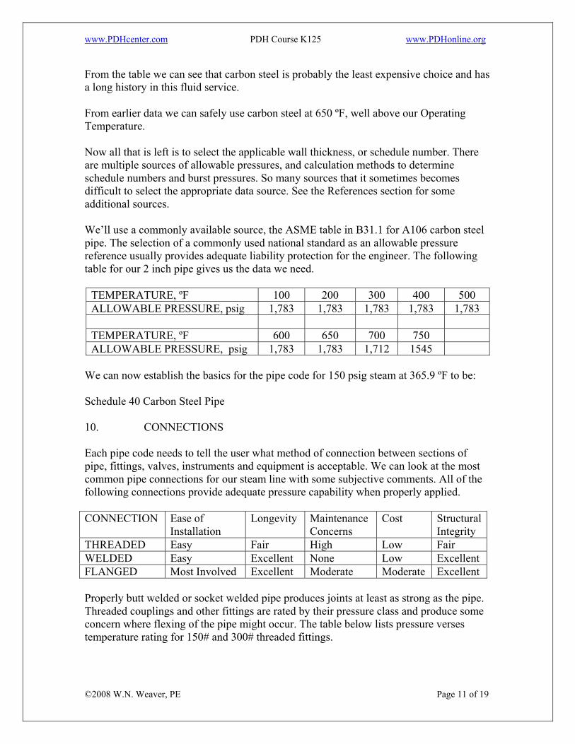
From the table we can see that carbon steel is probably the least expensive choice and has a long history in this fluid service. From earlier data we can safely use carbon steel at 650 ºF, well above our Operating Temperature. Now all that is left is to select the applicable wall thickness, or schedule number. There are multiple sources of allowable pressures, and calculation methods to determine schedule numbers and burst pressures. So many sources that it sometimes becomes difficult to select the appropriate data source. See the References section for some additional sources. We’ll use a commonly available source, the ASME table in B31.1 for A106 carbon steel pipe. The selection of a commonly used national standard as an allowable pressure reference usually provides adequate liability protection for the engineer. The following table for our 2 inch pipe gives us the data we need.
TEMPERATURE, ºF 100 200 300 400 500 ALLOWABLE PRESSURE, psig 1,783 1,783 1,783 1,783 1,783 TEMPERATURE, ºF 600 650 700 750 ALLOWABLE PRESSURE, psig 1,783 1,783 1,712 1545
We can now establish the basics for the pipe code for 150 psig steam at 365.9 ºF to be: Schedule 40 Carbon Steel Pipe 10. CONNECTIONS Each pipe code needs to tell the user what method of connection between sections of pipe, fittings, valves, instruments and equipment is acceptable. We can look at the most common pipe connections for our steam line with some subjective comments. All of the following connections provide adequate pressure capability when properly applied. CONNECTION Ease of
Installation Longevity Maintenance
Concerns Cost Structural
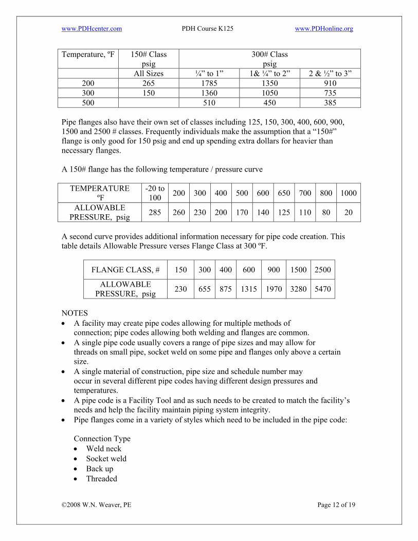
Integrity THREADED Easy Fair High Low Fair WELDED Easy Excellent None Low Excellent FLANGED Most Involved Excellent Moderate Moderate Excellent Properly butt welded or socket welded pipe produces joints at least as strong as the pipe. Threaded couplings and other fittings are rated by their pressure class and produce some concern where flexing of the pipe might occur. The table below lists pressure verses temperature rating for 150# and 300# threaded fittings.
©2008 W.N. Weaver, PE Page 11 of 19
www.PDHcenter.com PDH Course K125 www.PDHonline.org
Temperature, ºF 150# Class psig
300# Class psig
All Sizes ¼” to 1” 1& ¼” to 2” 2 & ½” to 3” 200 265 1785 1350 910 300 150 1360 1050 735 500 510 450 385
Pipe flanges also have their own set of classes including 125, 150, 300, 400, 600, 900, 1500 and 2500 # classes. Frequently individuals make the assumption that a “150#” flange is only good for 150 psig and end up spending extra dollars for heavier than necessary flanges. A 150# flange has the following temperature / pressure curve
TEMPERATURE ºF
-20 to 100 200 300 400 500 600 650 700 800 1000
ALLOWABLE PRESSURE, psig 285 260 230 200 170 140 125 110 80 20
A second curve provides additional information necessary for pipe code creation. This table details Allowable Pressure verses Flange Class at 300 ºF.
FLANGE CLASS, # 150 300 400 600 900 1500 2500
ALLOWABLE PRESSURE, psig 230 655 875 1315 1970 3280 5470
NOTES • A facility may create pipe codes allowing for multiple methods of
connection; pipe codes allowing both welding and flanges are common. • A single pipe code usually covers a range of pipe sizes and may allow for
threads on small pipe, socket weld on some pipe and flanges only above a certain size.
• A single material of construction, pipe size and schedule number may occur in several different pipe codes having different design pressures and temperatures.
• A pipe code is a Facility Tool and as such needs to be created to match the facility’s needs and help the facility maintain piping system integrity.
• Pipe flanges come in a variety of styles which need to be included in the pipe code:
Connection Type • Weld neck • Socket weld • Back up
©2008 W.N. Weaver, PE Page 12 of 19
• Threaded
www.PDHcenter.com PDH Course K125 www.PDHonline.org
• Various specialty types And several gasket face types • Flat faced • Lapped • Ring Joint • Raised face • Large male / female • Small male / female • Various specialty types
For the flange to hold the design pressure several things must be correct: • Gasket surfaces must be flat and in good condition • The proper gasket must be specified • The proper bolts torqued to the proper amount must be installed For welded joints to perform up to the design conditions the welds must be proper and the pipe fit up correct. For threaded fittings the threads must be clean, properly cut, have the proper pipe dope and have the proper amount of thread engagement. 11. WHAT DO WE HAVE SO FAR? For our steam pipe code we have the following items: Material of Construction: Carbon Steel Schedule for 150 psig: Schedule 40 pipe is acceptable being rated at 1783
psig at 400 ºF Connections: 150 # flanges or welded
(a 150# flange is acceptable for 200 psig for an operating temperature of 400 ºF which gives us a 50 psi and about 40 ºF tolerance) 300# threaded connections are good up to 280 psig (interpolated from table data to 365.9 ºF)
12. WHAT IS LEFT? Determining the extent of the pipe code contents is influenced by the fluid contents of the pipe, system pressure, temperature, installation environment, facility needs and available engineering time. The following provides guidance for the remaining items which can be beneficial if incorporated into a pipe code.
©2008 W.N. Weaver, PE Page 13 of 19
www.PDHcenter.com PDH Course K125 www.PDHonline.org
13. VALVES Generally a code will provide a variety of acceptable valves depending on the need. Those include gate, globe, ball, plug and specialty valves. Generally the valve type is listed along with acceptable model numbers and manufacturer’s names. Also listed are the acceptable connections for each valve type. Because of it size the listing of acceptable valves is usually separate from the pipe code and contains reference numbers for use on P&ID’s and piping arrangements. See the attached sample.
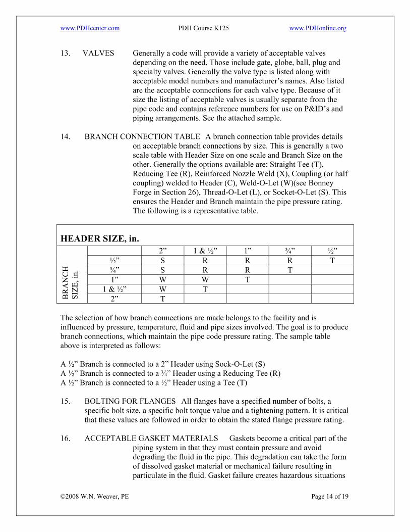
14. BRANCH CONNECTION TABLE A branch connection table provides details
on acceptable branch connections by size. This is generally a two scale table with Header Size on one scale and Branch Size on the other. Generally the options available are: Straight Tee (T), Reducing Tee (R), Reinforced Nozzle Weld (X), Coupling (or half coupling) welded to Header (C), Weld-O-Let (W)(see Bonney Forge in Section 26), Thread-O-Let (L), or Socket-O-Let (S). This ensures the Header and Branch maintain the pipe pressure rating. The following is a representative table.
HEADER SIZE, in. 2” 1 & ½” 1” ¾” ½”
½” S R R R T ¾” S R R T 1” W W T
1 & ½” W T
BR
AN
CH
SI
ZE, i
n.
2” T The selection of how branch connections are made belongs to the facility and is influenced by pressure, temperature, fluid and pipe sizes involved. The goal is to produce branch connections, which maintain the pipe code pressure rating. The sample table above is interpreted as follows: A ½” Branch is connected to a 2” Header using Sock-O-Let (S) A ½” Branch is connected to a ¾” Header using a Reducing Tee (R) A ½” Branch is connected to a ½” Header using a Tee (T) 15. BOLTING FOR FLANGES All flanges have a specified number of bolts, a
specific bolt size, a specific bolt torque value and a tightening pattern. It is critical that these values are followed in order to obtain the stated flange pressure rating.
16. ACCEPTABLE GASKET MATERIALS Gaskets become a critical part of the
©2008 W.N. Weaver, PE Page 14 of 19
piping system in that they must contain pressure and avoid degrading the fluid in the pipe. This degradation can take the form of dissolved gasket material or mechanical failure resulting in particulate in the fluid. Gasket failure creates hazardous situations
www.PDHcenter.com PDH Course K125 www.PDHonline.org
including toxic fumes, flammable vapor or liquid releases and personnel injury. Gasket selection should be handled by the same team that established materials of construction for the piping system.
Each flange has a gasket surface, which must be protected from scratches and other damage. Gasket materials have a specific bolt torque requirement, which may not be the same as the minimum for the flange itself. This torque value is established by the gasket manufacturer and is designed to prevent gasket blow out at the rated allowable pressure of the flange. A proper pipe code will contain gasket types with required torque values and thickness for each pipe size, temperature and pressure.
17. REINFORCING REQUIREMENTS (reinforcing pads) Are generally a part of the Header – Branch table and are established by specific calculations or data from a reference source such as ASME.
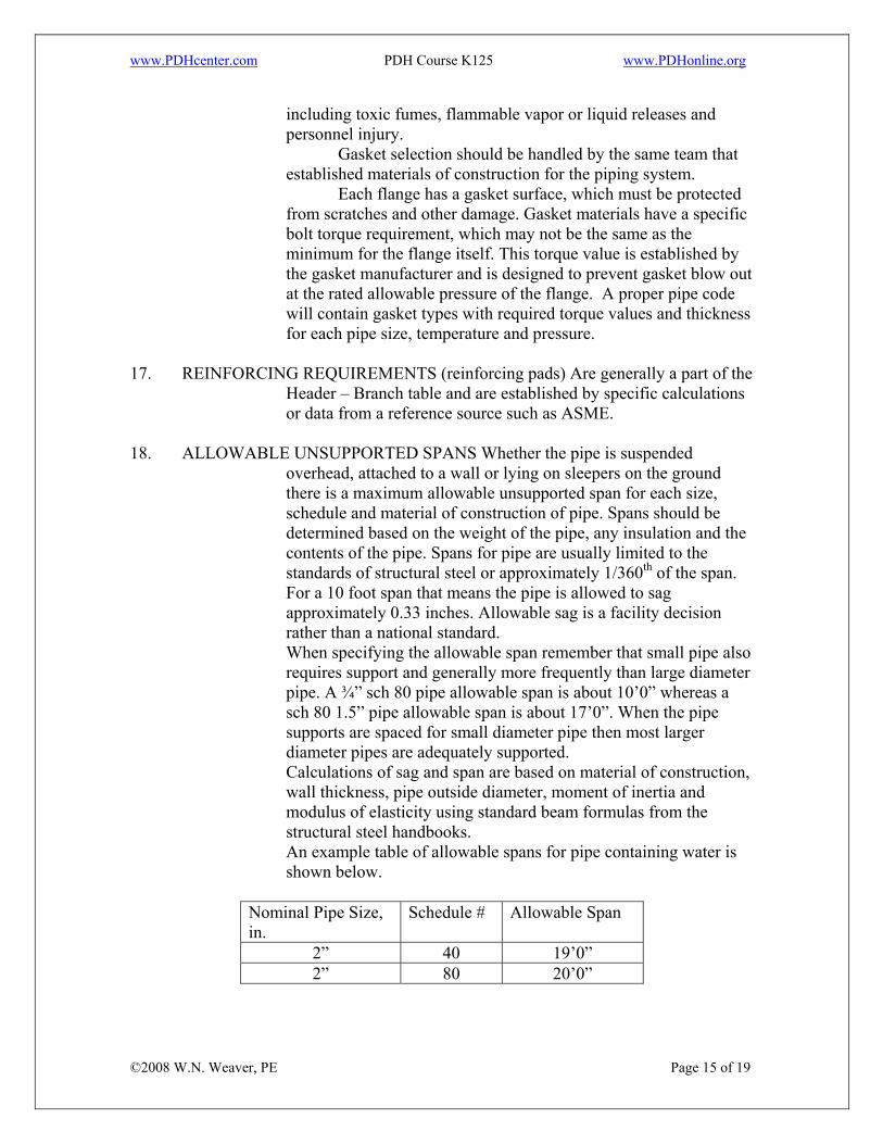
18. ALLOWABLE UNSUPPORTED SPANS Whether the pipe is suspended
overhead, attached to a wall or lying on sleepers on the ground there is a maximum allowable unsupported span for each size, schedule and material of construction of pipe. Spans should be determined based on the weight of the pipe, any insulation and the contents of the pipe. Spans for pipe are usually limited to the standards of structural steel or approximately 1/360th of the span. For a 10 foot span that means the pipe is allowed to sag approximately 0.33 inches. Allowable sag is a facility decision rather than a national standard. When specifying the allowable span remember that small pipe also requires support and generally more frequently than large diameter pipe. A ¾” sch 80 pipe allowable span is about 10’0” whereas a sch 80 1.5” pipe allowable span is about 17’0”. When the pipe supports are spaced for small diameter pipe then most larger diameter pipes are adequately supported. Calculations of sag and span are based on material of construction, wall thickness, pipe outside diameter, moment of inertia and modulus of elasticity using standard beam formulas from the structural steel handbooks. An example table of allowable spans for pipe containing water is shown below.
Nominal Pipe Size, in.
Schedule # Allowable Span
2” 40 19’0” 2” 80 20’0”
©2008 W.N. Weaver, PE Page 15 of 19
www.PDHcenter.com PDH Course K125 www.PDHonline.org
19. SURFACE PROTECTION REQUIRED This is another item best determined by the corrosion and gasket team and is influenced by installation conditions, materials of construction, insulation, and temperature. If the plant has a specific Surface Protection standard it should be referenced in the Pipe Code along with any required color coding for the pipe’s contents.
20. ACCEPTABLE INSULATION This is another item best determined by
the corrosion and gasket team with input from the facility maintenance and energy representatives and is influenced by installation conditions, materials of construction, insulation type, temperature and energy policy.
21. HEAT TRACING Depending on the type of heat tracing in use there may be a
need for a Heat Trace Pipe Code. Generally heat tracing is accomplished using hot water, hot oil, steam or electric heat wire. Most fluid trace system use copper or stainless steel tubing as the trace piping and details on how it should be specified and installed should be incorporated into a pipe code.
22. HEAT OR COOLING JACKETING Pipe jackets are a separate pipe code and require sketches and considerable detail for a pipe code. Jacket pipe codes contain two sections: one for the core or inner pipe and one for the jacketing pipe. This is generally a stand alone code rather than a portion of another code and incorporates a variety of information: Pipe to be jacketed Desired temperature within core pipe Pressure in core pipe Materials of construction of core pipe Connection details for branches in core pipe Jacketing pipe with sizes related to the core pipe Jacketing pipe schedule Jacketing termination at valves, fittings and equipment Jacket connections and flow patterns Jacket spacers designed to hold the jacket off the core pipe This can quickly become very complicated and it may be necessary to develop a jacketing standard independent of the pipe codes in order to put in all the necessary details.
©2008 W.N. Weaver, PE Page 16 of 19
23. ANCHORING All pipe requires support (see section on allowable spans) and how the supporting is accomplished is a critical detail. Supports include the following items: Rigid anchors Guides (to allow for thermal expansion or other movement) Thrust blocks
www.PDHcenter.com PDH Course K125 www.PDHonline.org
Pipe shoes (protects pipe from structural members which support it) Trapeze hangers Simple rod hangers Spring loaded hangers (hanging and stool) Rigid clamps (simple U-bolts) Roller supports
Supporting pipe requires considerable information about the stresses in the pipe and the resulting loads transferred by or to the supports. Simple straight runs of pipe rarely cause serious problems in the determination of the loads generated by the pipe in operation and for these the selection of techniques for anchoring the pipe is fairly simple. As pipe stresses increase because of heating, wind, equipment growth or vibration it becomes more important to do a detailed analysis of the required supporting systems. Pipe codes do not usually address any but the simplest anchoring requirements.
24. TESTING Testing is an essential part of installation of successful piping systems. Most engineers test piping systems to 1.5 times the design pressure and generally do this with water. Several questions always arise: • What do we do when the piping system is to handle hot oil and cannot be completely
drained of the testing water? • What do we do when the design pressure is specified at an elevated temperature? • Is it necessary to test low pressure systems at 1.5 times design pressure? • Can we do pneumatic testing instead of hydrostatic testing? For systems handling hot oil, chemicals which might react with water and create corrosive conditions or when the pipe line must be dry or when there might be damage to a lining or freezing using water then fluids other than water may be considered. For example pressurization might be carried out with non flammable liquids, antifreeze solutions, or some other compatible liquid. When the design temperature is higher than the test temperature the following calculation can be used to establish a minimum test pressure. Pt = 1.5P St where: Pt = low temperature test pressure (psig) S P = Internal Design Gage Pressure (psig) St = Allowable stress at test temperature, psi S = Allowable stress at design temperature, psi Care must be taken using this calculation and it is critical to review ASME B31.3 during the calculation phase whenever this testing situation occurs.
©2008 W.N. Weaver, PE Page 17 of 19
www.PDHcenter.com PDH Course K125 www.PDHonline.org
When dealing with low pressure systems carrying non toxic, non environmentally damaging fluids which offer no hazards to life testing may, at the engineer’s discretion consist of a “tightness test” only. Basically a static liquid filled line with no pressure applied. The choice of testing fluids (water or air, etc) belongs to some extent to the engineer, to recognized national standards and codes, the insurance company and local or national authorities. Research in creating the pipe code usually will provide sufficient information to guide the engineer in selecting the proper test procedure. Incorporating the test procedure into the pipe code eliminates confusion and problems later. CAUTION 1: It is generally not a good idea to pressurize equipment connected to piping systems during pressure testing. CAUTION 2: Using air for pressure testing must be considered very carefully. Pipe failure under liquid pressure generally results in a short spurt of water whereas with air the failure may well become explosive. CAUTION 3: Frequently instrumentation is removed or valved off during hydrostatic testing. 25. PIPE FABRICATION Metallic pipe can be fabricated in several ways and is classified in such as way as to define the manufacturing technique. Cast Iron Cast in a foundry and generally not part of a process industry except for some
utilities and drainage. Seamless Essentially extruded in some fashion around a mandrel. Considered to be the
best pipe since there is no seam to offer a weak spot or allow corrosion to begin..
ERW Electric Resistance Welded in an automatic machine as the formed pipe exits a forming machine.
This becomes a team decision as ERW is usually somewhat less expensive than seamless. 26. CONCLUSION Properly prepared pipe codes provide a variety of services to the facility engineer including: • increased fluid safety • reduced detail creation for bidding purposes • consistent treatment of various chemicals and utility fluids • minimal and consistent piping system costs • simplified instructions transfer to contractors and maintenance • improved detail in P&ID’s
©2008 W.N. Weaver, PE Page 18 of 19
• satisfaction of legal and insurance requirements
www.PDHcenter.com PDH Course K125 www.PDHonline.org
The effort required may seem significant but by utilizing existing codes as a starting point the task is simplified and the result worth the effort in future time saved and problems avoided. A completed pipe code standard relieves the engineer of having to re-invent the code each time a piping project is approved. 27. REFERENCES “Perry’s Chemical Engineer’s Handbook” McGraw-Hill Mark’s “Mechanical Engineer’s Handbook”, McGraw-Hill ASME various codes McCabe and Smith “Unit Operations of Chemical Engineering” Engineering Toolbox, www.Engineeringtoolbox.comBonney Forge, Mount Union, PA
©2008 W.N. Weaver, PE Page 19 of 19