Embed Size (px)
Citation preview
Department of Transport
Bureau of Air Safety Investigation
INVESTIGATION REPORT
9302851
Piper PA-31-350 Chieftain VH-WGILaunceston Tasmania
17 September 1993
Released by the Director of the Bureau of Air Safety Investigationunder the provisions of Air Navigation Regulation 283
ii
This report was produced by the Bureau of Air Safety Investigation (BASI), PO Box 967, Civic Square ACT 2608.
The Director of the Bureau authorised the investigation and the publication of this report pursuant to his delegated powersconferred by Air Navigation Regulations 278 and 283 respectively. Readers are advised that the Bureau investigates for thesole purpose of enhancing aviation safety. Consequently, Bureau reports are confined to matters of safety significance andmay be misleading if used for any other purpose.
As BASI believes that safety information is of greatest value if it is passed on for the use of others, copyright restrictions donot apply to material printed in this report. Readers are encouraged to copy or reprint for further distribution, but shouldacknowledge BASI as the source.
ISBN 0 642 23527 9 November 1995
When the Bureau makes recommendations as a resultof its investigations or research, safety (in accordancewith its charter) is its primary consideration. However,the Bureau fully recognises that the implementation ofrecommendations arising from its investigations will insome cases incur a cost to the industry.
Readers should note that the information in BASI reportsis provided to promote aviation safety: in no case is itintended to imply blame or liability.
iii
CONTENTS
GLOSSARY OF TERMS AND ABBREVIATIONS .... . . . . . . . . . . . . . . . . . . . . . . . . . . . . . . . . . . . . . . . . . . . . . . . . . . . . . . . . . . . . . . . . . . . . . . . . . . . . . . . . . . . . . . . . . . . . . . . . . . . . . . . . . . . . . . . . . . . . . . . . . vi
INTRODUCTION .... . . . . . . . . . . . . . . . . . . . . . . . . . . . . . . . . . . . . . . . . . . . . . . . . . . . . . . . . . . . . . . . . . . . . . . . . . . . . . . . . . . . . . . . . . . . . . . . . . . . . . . . . . . . . . . . . . . . . . . . . . . . . . . . . . . . . . . . . . . . . . . . . . . . . . . . . . . . . . . . . . . . . . . . . . . . . . . . . . . . . . . . . . . . . . . . . . . . . . . . . . . . . . . . . . . . . . . . . . . . . . 1
SYNOPSIS .. . . . . . . . . . . . . . . . . . . . . . . . . . . . . . . . . . . . . . . . . . . . . . . . . . . . . . . . . . . . . . . . . . . . . . . . . . . . . . . . . . . . . . . . . . . . . . . . . . . . . . . . . . . . . . . . . . . . . . . . . . . . . . . . . . . . . . . . . . . . . . . . . . . . . . . . . . . . . . . . . . . . . . . . . . . . . . . . . . . . . . . . . . . . . . . . . . . . . . . . . . . . . . . . . . . . . . . . . . . . . . . . . . . . . . . . . . . . . . . . . . . . . . . 3
1. FACTUAL INFORMATION ... . . . . . . . . . . . . . . . . . . . . . . . . . . . . . . . . . . . . . . . . . . . . . . . . . . . . . . . . . . . . . . . . . . . . . . . . . . . . . . . . . . . . . . . . . . . . . . . . . . . . . . . . . . . . . . . . . . . . . . . . . . . . . . . . . . . . . . . . . . . . . . . . . . . . . . . . . . . . . . . . . . . . . . . . . . . . . 3
1.1 History of the flight ... . . . . . . . . . . . . . . . . . . . . . . . . . . . . . . . . . . . . . . . . . . . . . . . . . . . . . . . . . . . . . . . . . . . . . . . . . . . . . . . . . . . . . . . . . . . . . . . . . . . . . . . . . . . . . . . . . . . . . . . . . . . . . . . . . . . . . . . . . . . . . . . . . . . . . . . . . . . . . . . . . . . . . . . . . . . 3
1.2 Injuries to persons .. . . . . . . . . . . . . . . . . . . . . . . . . . . . . . . . . . . . . . . . . . . . . . . . . . . . . . . . . . . . . . . . . . . . . . . . . . . . . . . . . . . . . . . . . . . . . . . . . . . . . . . . . . . . . . . . . . . . . . . . . . . . . . . . . . . . . . . . . . . . . . . . . . . . . . . . . . . . . . . . . . . . . . . . . . . . . . . . . . . . 6
1.3 Damage to aircraft .. . . . . . . . . . . . . . . . . . . . . . . . . . . . . . . . . . . . . . . . . . . . . . . . . . . . . . . . . . . . . . . . . . . . . . . . . . . . . . . . . . . . . . . . . . . . . . . . . . . . . . . . . . . . . . . . . . . . . . . . . . . . . . . . . . . . . . . . . . . . . . . . . . . . . . . . . . . . . . . . . . . . . . . . . . . . . . . . . . . . 6
1.4 Other damage .. . . . . . . . . . . . . . . . . . . . . . . . . . . . . . . . . . . . . . . . . . . . . . . . . . . . . . . . . . . . . . . . . . . . . . . . . . . . . . . . . . . . . . . . . . . . . . . . . . . . . . . . . . . . . . . . . . . . . . . . . . . . . . . . . . . . . . . . . . . . . . . . . . . . . . . . . . . . . . . . . . . . . . . . . . . . . . . . . . . . . . . . . . . . . . . . . . 6
1.5 Personnel information .. . . . . . . . . . . . . . . . . . . . . . . . . . . . . . . . . . . . . . . . . . . . . . . . . . . . . . . . . . . . . . . . . . . . . . . . . . . . . . . . . . . . . . . . . . . . . . . . . . . . . . . . . . . . . . . . . . . . . . . . . . . . . . . . . . . . . . . . . . . . . . . . . . . . . . . . . . . . . . . . . . . . . . . . 6
1.5.1 Pilot in command .. . . . . . . . . . . . . . . . . . . . . . . . . . . . . . . . . . . . . . . . . . . . . . . . . . . . . . . . . . . . . . . . . . . . . . . . . . . . . . . . . . . . . . . . . . . . . . . . . . . . . . . . . . . . . . . . . . . . . . . . . . . . . . . . . . . . . . . . . . . . . . . . . . . . 6
1.5.2 Previous 72 hours history .. . . . . . . . . . . . . . . . . . . . . . . . . . . . . . . . . . . . . . . . . . . . . . . . . . . . . . . . . . . . . . . . . . . . . . . . . . . . . . . . . . . . . . . . . . . . . . . . . . . . . . . . . . . . . . . . . . . . . . . . . . . 7
1.6 Aircraft information .. . . . . . . . . . . . . . . . . . . . . . . . . . . . . . . . . . . . . . . . . . . . . . . . . . . . . . . . . . . . . . . . . . . . . . . . . . . . . . . . . . . . . . . . . . . . . . . . . . . . . . . . . . . . . . . . . . . . . . . . . . . . . . . . . . . . . . . . . . . . . . . . . . . . . . . . . . . . . . . . . . . . . . . . . . . . . . . 8
1.6.1 Significant particulars .. . . . . . . . . . . . . . . . . . . . . . . . . . . . . . . . . . . . . . . . . . . . . . . . . . . . . . . . . . . . . . . . . . . . . . . . . . . . . . . . . . . . . . . . . . . . . . . . . . . . . . . . . . . . . . . . . . . . . . . . . . . . . . . . . . . . . . . 8
1.6.2 Aircraft history .. . . . . . . . . . . . . . . . . . . . . . . . . . . . . . . . . . . . . . . . . . . . . . . . . . . . . . . . . . . . . . . . . . . . . . . . . . . . . . . . . . . . . . . . . . . . . . . . . . . . . . . . . . . . . . . . . . . . . . . . . . . . . . . . . . . . . . . . . . . . . . . . . . . . . . . . . . . . . 8
1.6.3 Weight and balance .. . . . . . . . . . . . . . . . . . . . . . . . . . . . . . . . . . . . . . . . . . . . . . . . . . . . . . . . . . . . . . . . . . . . . . . . . . . . . . . . . . . . . . . . . . . . . . . . . . . . . . . . . . . . . . . . . . . . . . . . . . . . . . . . . . . . . . . . . . . . . . . 8
1.7 Meteorological information .. . . . . . . . . . . . . . . . . . . . . . . . . . . . . . . . . . . . . . . . . . . . . . . . . . . . . . . . . . . . . . . . . . . . . . . . . . . . . . . . . . . . . . . . . . . . . . . . . . . . . . . . . . . . . . . . . . . . . . . . . . . . . . . . . . . . . . . . . . . . . . . . . . . . . . . . 9
1.7.1 Introduction .. . . . . . . . . . . . . . . . . . . . . . . . . . . . . . . . . . . . . . . . . . . . . . . . . . . . . . . . . . . . . . . . . . . . . . . . . . . . . . . . . . . . . . . . . . . . . . . . . . . . . . . . . . . . . . . . . . . . . . . . . . . . . . . . . . . . . . . . . . . . . . . . . . . . . . . . . . . . . . . . . . . . . 9
1.7.2 Forecasts .. . . . . . . . . . . . . . . . . . . . . . . . . . . . . . . . . . . . . . . . . . . . . . . . . . . . . . . . . . . . . . . . . . . . . . . . . . . . . . . . . . . . . . . . . . . . . . . . . . . . . . . . . . . . . . . . . . . . . . . . . . . . . . . . . . . . . . . . . . . . . . . . . . . . . . . . . . . . . . . . . . . . . . . . . . . . . . . . . . 9
1.7.3 Weather conditions at Launceston .. . . . . . . . . . . . . . . . . . . . . . . . . . . . . . . . . . . . . . . . . . . . . . . . . . . . . . . . . . . . . . . . . . . . . . . . . . . . . . . . . . . . . . . . . . . . 10
1.8 Aids to navigation and instrument approaches .. . . . . . . . . . . . . . . . . . . . . . . . . . . . . . . . . . . . . . . . . . . . . . . . . . . . . . . . . . . . . . . . . . . . . . . . . . . . . . . . . . . . . . . . . . . 10
1.8.1 Aids to navigation .. . . . . . . . . . . . . . . . . . . . . . . . . . . . . . . . . . . . . . . . . . . . . . . . . . . . . . . . . . . . . . . . . . . . . . . . . . . . . . . . . . . . . . . . . . . . . . . . . . . . . . . . . . . . . . . . . . . . . . . . . . . . . . . . . . . . . . . . . . . . . . . . 10
1.8.2 Instrument approaches .. . . . . . . . . . . . . . . . . . . . . . . . . . . . . . . . . . . . . . . . . . . . . . . . . . . . . . . . . . . . . . . . . . . . . . . . . . . . . . . . . . . . . . . . . . . . . . . . . . . . . . . . . . . . . . . . . . . . . . . . . . . . . . . . 10
1.8.3 DME arrivals .. . . . . . . . . . . . . . . . . . . . . . . . . . . . . . . . . . . . . . . . . . . . . . . . . . . . . . . . . . . . . . . . . . . . . . . . . . . . . . . . . . . . . . . . . . . . . . . . . . . . . . . . . . . . . . . . . . . . . . . . . . . . . . . . . . . . . . . . . . . . . . . . . . . . . . . . . . . . . . . . . 11
1.8.4 Circling approaches .. . . . . . . . . . . . . . . . . . . . . . . . . . . . . . . . . . . . . . . . . . . . . . . . . . . . . . . . . . . . . . . . . . . . . . . . . . . . . . . . . . . . . . . . . . . . . . . . . . . . . . . . . . . . . . . . . . . . . . . . . . . . . . . . . . . . . . . . . . . 12
1.9 Communications .. . . . . . . . . . . . . . . . . . . . . . . . . . . . . . . . . . . . . . . . . . . . . . . . . . . . . . . . . . . . . . . . . . . . . . . . . . . . . . . . . . . . . . . . . . . . . . . . . . . . . . . . . . . . . . . . . . . . . . . . . . . . . . . . . . . . . . . . . . . . . . . . . . . . . . . . . . . . . . . . . . . . . . . . . . . . . . . . . . . . . . 13
1.9.1 Summary of communications .. . . . . . . . . . . . . . . . . . . . . . . . . . . . . . . . . . . . . . . . . . . . . . . . . . . . . . . . . . . . . . . . . . . . . . . . . . . . . . . . . . . . . . . . . . . . . . . . . . . . . . . . . . 13
1.10 Aerodrome information .. . . . . . . . . . . . . . . . . . . . . . . . . . . . . . . . . . . . . . . . . . . . . . . . . . . . . . . . . . . . . . . . . . . . . . . . . . . . . . . . . . . . . . . . . . . . . . . . . . . . . . . . . . . . . . . . . . . . . . . . . . . . . . . . . . . . . . . . . . . . . . . . . . . . . . . . . . . . . . . . . 16
1.10.1 General .. . . . . . . . . . . . . . . . . . . . . . . . . . . . . . . . . . . . . . . . . . . . . . . . . . . . . . . . . . . . . . . . . . . . . . . . . . . . . . . . . . . . . . . . . . . . . . . . . . . . . . . . . . . . . . . . . . . . . . . . . . . . . . . . . . . . . . . . . . . . . . . . . . . . . . . . . . . . . . . . . . . . . . . . . . . . . . . . . . . 16
1.10.2 Lighting .. . . . . . . . . . . . . . . . . . . . . . . . . . . . . . . . . . . . . . . . . . . . . . . . . . . . . . . . . . . . . . . . . . . . . . . . . . . . . . . . . . . . . . . . . . . . . . . . . . . . . . . . . . . . . . . . . . . . . . . . . . . . . . . . . . . . . . . . . . . . . . . . . . . . . . . . . . . . . . . . . . . . . . . . . . . . . . . . . 17
1.10.3 Other lighting .. . . . . . . . . . . . . . . . . . . . . . . . . . . . . . . . . . . . . . . . . . . . . . . . . . . . . . . . . . . . . . . . . . . . . . . . . . . . . . . . . . . . . . . . . . . . . . . . . . . . . . . . . . . . . . . . . . . . . . . . . . . . . . . . . . . . . . . . . . . . . . . . . . . . . . . . . . . . . . 18
1.11 Flight recorders/GPWS .. . . . . . . . . . . . . . . . . . . . . . . . . . . . . . . . . . . . . . . . . . . . . . . . . . . . . . . . . . . . . . . . . . . . . . . . . . . . . . . . . . . . . . . . . . . . . . . . . . . . . . . . . . . . . . . . . . . . . . . . . . . . . . . . . . . . . . . . . . . . . . . . . . . . . . . . . . . . . . . . . . . . 18
1.12 Wreckage and impact information ... . . . . . . . . . . . . . . . . . . . . . . . . . . . . . . . . . . . . . . . . . . . . . . . . . . . . . . . . . . . . . . . . . . . . . . . . . . . . . . . . . . . . . . . . . . . . . . . . . . . . . . . . . . . . . . . . . . . . . . . . . 18
1.12.1 Accident site description .. . . . . . . . . . . . . . . . . . . . . . . . . . . . . . . . . . . . . . . . . . . . . . . . . . . . . . . . . . . . . . . . . . . . . . . . . . . . . . . . . . . . . . . . . . . . . . . . . . . . . . . . . . . . . . . . . . . . . . . . . . . . 18
1.12.2 Aircraft path/wreckage trail .. . . . . . . . . . . . . . . . . . . . . . . . . . . . . . . . . . . . . . . . . . . . . . . . . . . . . . . . . . . . . . . . . . . . . . . . . . . . . . . . . . . . . . . . . . . . . . . . . . . . . . . . . . . . . . . . . . 19
1.12.3 Structure .. . . . . . . . . . . . . . . . . . . . . . . . . . . . . . . . . . . . . . . . . . . . . . . . . . . . . . . . . . . . . . . . . . . . . . . . . . . . . . . . . . . . . . . . . . . . . . . . . . . . . . . . . . . . . . . . . . . . . . . . . . . . . . . . . . . . . . . . . . . . . . . . . . . . . . . . . . . . . . . . . . . . . . . . . . . . . . 20
1.12.4 Flight controls .. . . . . . . . . . . . . . . . . . . . . . . . . . . . . . . . . . . . . . . . . . . . . . . . . . . . . . . . . . . . . . . . . . . . . . . . . . . . . . . . . . . . . . . . . . . . . . . . . . . . . . . . . . . . . . . . . . . . . . . . . . . . . . . . . . . . . . . . . . . . . . . . . . . . . . . . . . . . . 20
1.12.5 Power plants .. . . . . . . . . . . . . . . . . . . . . . . . . . . . . . . . . . . . . . . . . . . . . . . . . . . . . . . . . . . . . . . . . . . . . . . . . . . . . . . . . . . . . . . . . . . . . . . . . . . . . . . . . . . . . . . . . . . . . . . . . . . . . . . . . . . . . . . . . . . . . . . . . . . . . . . . . . . . . . . . . . . 20
1.12.6 Propellers .. . . . . . . . . . . . . . . . . . . . . . . . . . . . . . . . . . . . . . . . . . . . . . . . . . . . . . . . . . . . . . . . . . . . . . . . . . . . . . . . . . . . . . . . . . . . . . . . . . . . . . . . . . . . . . . . . . . . . . . . . . . . . . . . . . . . . . . . . . . . . . . . . . . . . . . . . . . . . . . . . . . . . . . . . . . . 21
1.12.7 Landing gear and hydraulic power .. . . . . . . . . . . . . . . . . . . . . . . . . . . . . . . . . . . . . . . . . . . . . . . . . . . . . . . . . . . . . . . . . . . . . . . . . . . . . . . . . . . . . . . . . . . . 21
1.12.8 Fuel system ... . . . . . . . . . . . . . . . . . . . . . . . . . . . . . . . . . . . . . . . . . . . . . . . . . . . . . . . . . . . . . . . . . . . . . . . . . . . . . . . . . . . . . . . . . . . . . . . . . . . . . . . . . . . . . . . . . . . . . . . . . . . . . . . . . . . . . . . . . . . . . . . . . . . . . . . . . . . . . . . . . . . . . 21
1.12.9 Instruments .. . . . . . . . . . . . . . . . . . . . . . . . . . . . . . . . . . . . . . . . . . . . . . . . . . . . . . . . . . . . . . . . . . . . . . . . . . . . . . . . . . . . . . . . . . . . . . . . . . . . . . . . . . . . . . . . . . . . . . . . . . . . . . . . . . . . . . . . . . . . . . . . . . . . . . . . . . . . . . . . . . . . . 22
1.12.10 Remaining systems .. . . . . . . . . . . . . . . . . . . . . . . . . . . . . . . . . . . . . . . . . . . . . . . . . . . . . . . . . . . . . . . . . . . . . . . . . . . . . . . . . . . . . . . . . . . . . . . . . . . . . . . . . . . . . . . . . . . . . . . . . . . . . . . . . . . . . . . . . . . . . . 22
1.12.11 Maintenance history .. . . . . . . . . . . . . . . . . . . . . . . . . . . . . . . . . . . . . . . . . . . . . . . . . . . . . . . . . . . . . . . . . . . . . . . . . . . . . . . . . . . . . . . . . . . . . . . . . . . . . . . . . . . . . . . . . . . . . . . . . . . . . . . . . . . . . . . . . 22
1.13 Medical and pathological information ... . . . . . . . . . . . . . . . . . . . . . . . . . . . . . . . . . . . . . . . . . . . . . . . . . . . . . . . . . . . . . . . . . . . . . . . . . . . . . . . . . . . . . . . . . . . . . . . . . . . . . . . . . . . . . . . 22
1.13.1 Post-mortem examinations .. . . . . . . . . . . . . . . . . . . . . . . . . . . . . . . . . . . . . . . . . . . . . . . . . . . . . . . . . . . . . . . . . . . . . . . . . . . . . . . . . . . . . . . . . . . . . . . . . . . . . . . . . . . . . . . . . . . 22
1.13.2 Alcohol levels/passenger behaviour .. . . . . . . . . . . . . . . . . . . . . . . . . . . . . . . . . . . . . . . . . . . . . . . . . . . . . . . . . . . . . . . . . . . . . . . . . . . . . . . . . . . . . . . . . . 22
1.14 Fire .. . . . . . . . . . . . . . . . . . . . . . . . . . . . . . . . . . . . . . . . . . . . . . . . . . . . . . . . . . . . . . . . . . . . . . . . . . . . . . . . . . . . . . . . . . . . . . . . . . . . . . . . . . . . . . . . . . . . . . . . . . . . . . . . . . . . . . . . . . . . . . . . . . . . . . . . . . . . . . . . . . . . . . . . . . . . . . . . . . . . . . . . . . . . . . . . . . . . . . . . . . . . . . . . . . . . . . . . . . . . . . . . 23
1.15 Survival aspects .. . . . . . . . . . . . . . . . . . . . . . . . . . . . . . . . . . . . . . . . . . . . . . . . . . . . . . . . . . . . . . . . . . . . . . . . . . . . . . . . . . . . . . . . . . . . . . . . . . . . . . . . . . . . . . . . . . . . . . . . . . . . . . . . . . . . . . . . . . . . . . . . . . . . . . . . . . . . . . . . . . . . . . . . . . . . . . . . . . . . . . . . . . . 24
1.15.1 Crashworthiness and survivability .. . . . . . . . . . . . . . . . . . . . . . . . . . . . . . . . . . . . . . . . . . . . . . . . . . . . . . . . . . . . . . . . . . . . . . . . . . . . . . . . . . . . . . . . . . . . . 24
1.15.2 Emergency services response .. . . . . . . . . . . . . . . . . . . . . . . . . . . . . . . . . . . . . . . . . . . . . . . . . . . . . . . . . . . . . . . . . . . . . . . . . . . . . . . . . . . . . . . . . . . . . . . . . . . . . . . . . . . . . . 25
1.16 CAA/operator/industry .. . . . . . . . . . . . . . . . . . . . . . . . . . . . . . . . . . . . . . . . . . . . . . . . . . . . . . . . . . . . . . . . . . . . . . . . . . . . . . . . . . . . . . . . . . . . . . . . . . . . . . . . . . . . . . . . . . . . . . . . . . . . . . . . . . . . . . . . . . . . . . . . . . . . . . . . . . . . . . . . . . . 25
1.16.1 CAA responsibilities ... . . . . . . . . . . . . . . . . . . . . . . . . . . . . . . . . . . . . . . . . . . . . . . . . . . . . . . . . . . . . . . . . . . . . . . . . . . . . . . . . . . . . . . . . . . . . . . . . . . . . . . . . . . . . . . . . . . . . . . . . . . . . . . . . . . . . . . . . 25
1.16.2 Operator history/responsibilities ... . . . . . . . . . . . . . . . . . . . . . . . . . . . . . . . . . . . . . . . . . . . . . . . . . . . . . . . . . . . . . . . . . . . . . . . . . . . . . . . . . . . . . . . . . . . . . . . . . . 27
1.16.3 Industry endorsement procedures .. . . . . . . . . . . . . . . . . . . . . . . . . . . . . . . . . . . . . . . . . . . . . . . . . . . . . . . . . . . . . . . . . . . . . . . . . . . . . . . . . . . . . . . . . . . . . . . . . . . . . 28
1.17 Pilot procedures .. . . . . . . . . . . . . . . . . . . . . . . . . . . . . . . . . . . . . . . . . . . . . . . . . . . . . . . . . . . . . . . . . . . . . . . . . . . . . . . . . . . . . . . . . . . . . . . . . . . . . . . . . . . . . . . . . . . . . . . . . . . . . . . . . . . . . . . . . . . . . . . . . . . . . . . . . . . . . . . . . . . . . . . . . . . . . . . . . . . . . . . . . 29
1.18 Other aircraft en route Moorabbin–Launceston .. . . . . . . . . . . . . . . . . . . . . . . . . . . . . . . . . . . . . . . . . . . . . . . . . . . . . . . . . . . . . . . . . . . . . . . . . . . . . . . . . . . . . . . . 29
1.19 Recorded radar data .. . . . . . . . . . . . . . . . . . . . . . . . . . . . . . . . . . . . . . . . . . . . . . . . . . . . . . . . . . . . . . . . . . . . . . . . . . . . . . . . . . . . . . . . . . . . . . . . . . . . . . . . . . . . . . . . . . . . . . . . . . . . . . . . . . . . . . . . . . . . . . . . . . . . . . . . . . . . . . . . . . . . . . . . . . . . . 30
1.20 Visual illusions/vision obstruction .. . . . . . . . . . . . . . . . . . . . . . . . . . . . . . . . . . . . . . . . . . . . . . . . . . . . . . . . . . . . . . . . . . . . . . . . . . . . . . . . . . . . . . . . . . . . . . . . . . . . . . . . . . . . . . . . . . . . . . . . . . . . . . . . . 31
1.21 ATS-related matters .. . . . . . . . . . . . . . . . . . . . . . . . . . . . . . . . . . . . . . . . . . . . . . . . . . . . . . . . . . . . . . . . . . . . . . . . . . . . . . . . . . . . . . . . . . . . . . . . . . . . . . . . . . . . . . . . . . . . . . . . . . . . . . . . . . . . . . . . . . . . . . . . . . . . . . . . . . . . . . . . . . . . . . . . . . . . . . 31
1.22 Tests and research .. . . . . . . . . . . . . . . . . . . . . . . . . . . . . . . . . . . . . . . . . . . . . . . . . . . . . . . . . . . . . . . . . . . . . . . . . . . . . . . . . . . . . . . . . . . . . . . . . . . . . . . . . . . . . . . . . . . . . . . . . . . . . . . . . . . . . . . . . . . . . . . . . . . . . . . . . . . . . . . . . . . . . . . . . . . . . . . . . . . . 31
1.22.1 Flight test ... . . . . . . . . . . . . . . . . . . . . . . . . . . . . . . . . . . . . . . . . . . . . . . . . . . . . . . . . . . . . . . . . . . . . . . . . . . . . . . . . . . . . . . . . . . . . . . . . . . . . . . . . . . . . . . . . . . . . . . . . . . . . . . . . . . . . . . . . . . . . . . . . . . . . . . . . . . . . . . . . . . . . . . . . . . 31
1.22.2 Audio tape monitor/analysis ... . . . . . . . . . . . . . . . . . . . . . . . . . . . . . . . . . . . . . . . . . . . . . . . . . . . . . . . . . . . . . . . . . . . . . . . . . . . . . . . . . . . . . . . . . . . . . . . . . . . . . . . . . . . . . . 32
1.22.3 Assessment of bank angles at night ... . . . . . . . . . . . . . . . . . . . . . . . . . . . . . . . . . . . . . . . . . . . . . . . . . . . . . . . . . . . . . . . . . . . . . . . . . . . . . . . . . . . . . . . . 33
1.22.4 Flight path on the circling approach ... . . . . . . . . . . . . . . . . . . . . . . . . . . . . . . . . . . . . . . . . . . . . . . . . . . . . . . . . . . . . . . . . . . . . . . . . . . . . . . . . . . . . 33
2. ANALYSIS .. . . . . . . . . . . . . . . . . . . . . . . . . . . . . . . . . . . . . . . . . . . . . . . . . . . . . . . . . . . . . . . . . . . . . . . . . . . . . . . . . . . . . . . . . . . . . . . . . . . . . . . . . . . . . . . . . . . . . . . . . . . . . . . . . . . . . . . . . . . . . . . . . . . . . . . . . . . . . . . . . . . . . . . . . . . . . . . . . . . . . . . . . . . . . . . . . . . . . . . . . . . . . . . . . . . . . . . . . . . . . . . . . . . 34
2.1 Introduction ................................................................................................................................................................................................................................ 34
2.2 Defences ... . . . . . . . . . . . . . . . . . . . . . . . . . . . . . . . . . . . . . . . . . . . . . . . . . . . . . . . . . . . . . . . . . . . . . . . . . . . . . . . . . . . . . . . . . . . . . . . . . . . . . . . . . . . . . . . . . . . . . . . . . . . . . . . . . . . . . . . . . . . . . . . . . . . . . . . . . . . . . . . . . . . . . . . . . . . . . . . . . . . . . . . . . . . . . . . . . . . . . . . . . . . . . 34
2.2.1 Absent defences ... . . . . . . . . . . . . . . . . . . . . . . . . . . . . . . . . . . . . . . . . . . . . . . . . . . . . . . . . . . . . . . . . . . . . . . . . . . . . . . . . . . . . . . . . . . . . . . . . . . . . . . . . . . . . . . . . . . . . . . . . . . . . . . . . . . . . . . . . . . . . . . . . . . . . . . . 34
2.2.2 Failed defences ... . . . . . . . . . . . . . . . . . . . . . . . . . . . . . . . . . . . . . . . . . . . . . . . . . . . . . . . . . . . . . . . . . . . . . . . . . . . . . . . . . . . . . . . . . . . . . . . . . . . . . . . . . . . . . . . . . . . . . . . . . . . . . . . . . . . . . . . . . . . . . . . . . . . . . . . . . . 34
2.2.3 Circumvented defences ... . . . . . . . . . . . . . . . . . . . . . . . . . . . . . . . . . . . . . . . . . . . . . . . . . . . . . . . . . . . . . . . . . . . . . . . . . . . . . . . . . . . . . . . . . . . . . . . . . . . . . . . . . . . . . . . . . . . . . . . . . . . . . . . 34
2.3 Active failures ... . . . . . . . . . . . . . . . . . . . . . . . . . . . . . . . . . . . . . . . . . . . . . . . . . . . . . . . . . . . . . . . . . . . . . . . . . . . . . . . . . . . . . . . . . . . . . . . . . . . . . . . . . . . . . . . . . . . . . . . . . . . . . . . . . . . . . . . . . . . . . . . . . . . . . . . . . . . . . . . . . . . . . . . . . . . . . . . . . . . . . . . . . . . . 35
2.3.1 Errors ... . . . . . . . . . . . . . . . . . . . . . . . . . . . . . . . . . . . . . . . . . . . . . . . . . . . . . . . . . . . . . . . . . . . . . . . . . . . . . . . . . . . . . . . . . . . . . . . . . . . . . . . . . . . . . . . . . . . . . . . . . . . . . . . . . . . . . . . . . . . . . . . . . . . . . . . . . . . . . . . . . . . . . . . . . . . . . . . . . . . . . . . 35
2.3.2 Violations ... . . . . . . . . . . . . . . . . . . . . . . . . . . . . . . . . . . . . . . . . . . . . . . . . . . . . . . . . . . . . . . . . . . . . . . . . . . . . . . . . . . . . . . . . . . . . . . . . . . . . . . . . . . . . . . . . . . . . . . . . . . . . . . . . . . . . . . . . . . . . . . . . . . . . . . . . . . . . . . . . . . . . . . . . . . 37
2.4 Preconditions ... . . . . . . . . . . . . . . . . . . . . . . . . . . . . . . . . . . . . . . . . . . . . . . . . . . . . . . . . . . . . . . . . . . . . . . . . . . . . . . . . . . . . . . . . . . . . . . . . . . . . . . . . . . . . . . . . . . . . . . . . . . . . . . . . . . . . . . . . . . . . . . . . . . . . . . . . . . . . . . . . . . . . . . . . . . . . . . . . . . . . . . . . . . . . . 37
2.4.1 Weather conditions ... . . . . . . . . . . . . . . . . . . . . . . . . . . . . . . . . . . . . . . . . . . . . . . . . . . . . . . . . . . . . . . . . . . . . . . . . . . . . . . . . . . . . . . . . . . . . . . . . . . . . . . . . . . . . . . . . . . . . . . . . . . . . . . . . . . . . . . . . . . . 37
2.4.2 Visual illusions ... . . . . . . . . . . . . . . . . . . . . . . . . . . . . . . . . . . . . . . . . . . . . . . . . . . . . . . . . . . . . . . . . . . . . . . . . . . . . . . . . . . . . . . . . . . . . . . . . . . . . . . . . . . . . . . . . . . . . . . . . . . . . . . . . . . . . . . . . . . . . . . . . . . . . . . . . . 38
2.4.3 Pilot inexperience ... . . . . . . . . . . . . . . . . . . . . . . . . . . . . . . . . . . . . . . . . . . . . . . . . . . . . . . . . . . . . . . . . . . . . . . . . . . . . . . . . . . . . . . . . . . . . . . . . . . . . . . . . . . . . . . . . . . . . . . . . . . . . . . . . . . . . . . . . . . . . . . . . 38
2.4.4 Instructions or procedures ... . . . . . . . . . . . . . . . . . . . . . . . . . . . . . . . . . . . . . . . . . . . . . . . . . . . . . . . . . . . . . . . . . . . . . . . . . . . . . . . . . . . . . . . . . . . . . . . . . . . . . . . . . . . . . . . . . . . 39
2.4.5 Unfamiliarity with task/high workload ... . . . . . . . . . . . . . . . . . . . . . . . . . . . . . . . . . . . . . . . . . . . . . . . . . . . . . . . . . . . . . . . . . . . . . . . . . . . . 39
2.4.6 Time pressures ... . . . . . . . . . . . . . . . . . . . . . . . . . . . . . . . . . . . . . . . . . . . . . . . . . . . . . . . . . . . . . . . . . . . . . . . . . . . . . . . . . . . . . . . . . . . . . . . . . . . . . . . . . . . . . . . . . . . . . . . . . . . . . . . . . . . . . . . . . . . . . . . . . . . . . . . . . . 40
2.5 Organisational factors ... . . . . . . . . . . . . . . . . . . . . . . . . . . . . . . . . . . . . . . . . . . . . . . . . . . . . . . . . . . . . . . . . . . . . . . . . . . . . . . . . . . . . . . . . . . . . . . . . . . . . . . . . . . . . . . . . . . . . . . . . . . . . . . . . . . . . . . . . . . . . . . . . . . . . . . . . . . . . . . . . . 41
2.5.1 Training ... . . . . . . . . . . . . . . . . . . . . . . . . . . . . . . . . . . . . . . . . . . . . . . . . . . . . . . . . . . . . . . . . . . . . . . . . . . . . . . . . . . . . . . . . . . . . . . . . . . . . . . . . . . . . . . . . . . . . . . . . . . . . . . . . . . . . . . . . . . . . . . . . . . . . . . . . . . . . . . . . . . . . . . . . . . . . . . . 41
2.5.2 Instructions or procedures ... . . . . . . . . . . . . . . . . . . . . . . . . . . . . . . . . . . . . . . . . . . . . . . . . . . . . . . . . . . . . . . . . . . . . . . . . . . . . . . . . . . . . . . . . . . . . . . . . . . . . . . . . . . . . . . . . . . . 42
2.5.3 Safety regulation ... . . . . . . . . . . . . . . . . . . . . . . . . . . . . . . . . . . . . . . . . . . . . . . . . . . . . . . . . . . . . . . . . . . . . . . . . . . . . . . . . . . . . . . . . . . . . . . . . . . . . . . . . . . . . . . . . . . . . . . . . . . . . . . . . . . . . . . . . . . . . . . . . . . . . 42
2.5.4 Control and monitoring by operator ... . . . . . . . . . . . . . . . . . . . . . . . . . . . . . . . . . . . . . . . . . . . . . . . . . . . . . . . . . . . . . . . . . . . . . . . . . . . . . . . . . . 43
2.6 Other matters ... . . . . . . . . . . . . . . . . . . . . . . . . . . . . . . . . . . . . . . . . . . . . . . . . . . . . . . . . . . . . . . . . . . . . . . . . . . . . . . . . . . . . . . . . . . . . . . . . . . . . . . . . . . . . . . . . . . . . . . . . . . . . . . . . . . . . . . . . . . . . . . . . . . . . . . . . . . . . . . . . . . . . . . . . . . . . . . . . . . . . . . . . . . . . 43
2.6.1 Emergency services response ... . . . . . . . . . . . . . . . . . . . . . . . . . . . . . . . . . . . . . . . . . . . . . . . . . . . . . . . . . . . . . . . . . . . . . . . . . . . . . . . . . . . . . . . . . . . . . . . . . . . . . . . . . . . . 43
2.6.2 Survival ... . . . . . . . . . . . . . . . . . . . . . . . . . . . . . . . . . . . . . . . . . . . . . . . . . . . . . . . . . . . . . . . . . . . . . . . . . . . . . . . . . . . . . . . . . . . . . . . . . . . . . . . . . . . . . . . . . . . . . . . . . . . . . . . . . . . . . . . . . . . . . . . . . . . . . . . . . . . . . . . . . . . . . . . . . . . . . . . . 44
iv
3. CONCLUSIONS .. . . . . . . . . . . . . . . . . . . . . . . . . . . . . . . . . . . . . . . . . . . . . . . . . . . . . . . . . . . . . . . . . . . . . . . . . . . . . . . . . . . . . . . . . . . . . . . . . . . . . . . . . . . . . . . . . . . . . . . . . . . . . . . . . . . . . . . . . . . . . . . . . . . . . . . . . . . . . . . . . . . . . . . . . . . . . . . . . . . . . . . . . . . . . . . . . . . . . . . . . . . . . . . . . . . . . . . . . . . . . . . . . . . . 45
3.1 Findings .. . . . . . . . . . . . . . . . . . . . . . . . . . . . . . . . . . . . . . . . . . . . . . . . . . . . . . . . . . . . . . . . . . . . . . . . . . . . . . . . . . . . . . . . . . . . . . . . . . . . . . . . . . . . . . . . . . . . . . . . . . . . . . . . . . . . . . . . . . . . . . . . . . . . . . . . . . . . . . . . . . . . . . . . . . . . . . . . . . . . . . . . . . . . . . . . . . . . . . . . . . . . . . . . . 45
3.2 Significant factors .. . . . . . . . . . . . . . . . . . . . . . . . . . . . . . . . . . . . . . . . . . . . . . . . . . . . . . . . . . . . . . . . . . . . . . . . . . . . . . . . . . . . . . . . . . . . . . . . . . . . . . . . . . . . . . . . . . . . . . . . . . . . . . . . . . . . . . . . . . . . . . . . . . . . . . . . . . . . . . . . . . . . . . . . . . . . . . . . . . . . 46
4. SAFETY ACTIONS .. . . . . . . . . . . . . . . . . . . . . . . . . . . . . . . . . . . . . . . . . . . . . . . . . . . . . . . . . . . . . . . . . . . . . . . . . . . . . . . . . . . . . . . . . . . . . . . . . . . . . . . . . . . . . . . . . . . . . . . . . . . . . . . . . . . . . . . . . . . . . . . . . . . . . . . . . . . . . . . . . . . . . . . . . . . . . . . . . . . . . . . . . . . . . . . . . . . . . . . 47
4.1 Interim recommendations .. . . . . . . . . . . . . . . . . . . . . . . . . . . . . . . . . . . . . . . . . . . . . . . . . . . . . . . . . . . . . . . . . . . . . . . . . . . . . . . . . . . . . . . . . . . . . . . . . . . . . . . . . . . . . . . . . . . . . . . . . . . . . . . . . . . . . . . . . . . . . . . . . . . . . . . . . . 47
4.2 Final recommendations ... . . . . . . . . . . . . . . . . . . . . . . . . . . . . . . . . . . . . . . . . . . . . . . . . . . . . . . . . . . . . . . . . . . . . . . . . . . . . . . . . . . . . . . . . . . . . . . . . . . . . . . . . . . . . . . . . . . . . . . . . . . . . . . . . . . . . . . . . . . . . . . . . . . . . . . . . . . . . . 51
4.3 Safety Advisory Notice .. . . . . . . . . . . . . . . . . . . . . . . . . . . . . . . . . . . . . . . . . . . . . . . . . . . . . . . . . . . . . . . . . . . . . . . . . . . . . . . . . . . . . . . . . . . . . . . . . . . . . . . . . . . . . . . . . . . . . . . . . . . . . . . . . . . . . . . . . . . . . . . . . . . . . . . . . . . . . . . . . . . . . 51
v
vi
GLOSSARY OF TERMS AND ABBREVIATIONS
AD Airworthiness Directive
ADC Aerodrome (Air Traffic) Controller
ADF Automatic Direction Finder
AGL Above Ground Level
AIP Aeronautical Information Publication
AMSL Above Mean Sea Level
AOC Air Operators Certificate
ARFOR Area Forecast(s)
ARP Aerodrome Reference Point
ATC Air Traffic Control
ATIS Automatic Terminal Information Service
ATS Air Traffic Services
AUW All-up Weight
AVR Automatic Voice Recorder
Ba Blood Alcohol
BASI Bureau of Air Safety Investigation
CAA Civil Aviation Authority
CAO Civil Aviation Order(s)
CAR Civil Aviation Regulation(s)
CFI Chief Flying Instructor
CG Centre of Gravity
CP Chief Pilot
CPL Commercial Pilot’s Licence
CVR Cockpit Voice Recorder
DA Decision Altitude
DAP Departure and Approach Procedures
DAM District Airworthiness Manager
DFOM District Flight Operations Manager
DI Directional Indicator
DME Distance Measuring Equipment (gives a read out of distance equivalent to nautical miles).
ERSA Enroute Supplement Australia (AIP)
EST Eastern Standard Time
FAF Final Approach Fix
FDR Flight Data Recorder
FIS Flight Information Service
FS Flight Service (in general)
FOI Flying Operations Inspector
GFPT General Flying Progress Test
GPWS Ground Proximity Warning System
g Acceleration due to Earth gravity
hPa Hectopascal(s)
HSI Horizontal Situation Indicator
IAL Instrument Approach and Landing
IAF Initial Approach Fix
ICAO International Civil Aviation Organisation
ICUS In Command Under Supervision
IFR Instrument Flight Rules
ILS Instrument Landing System
IMC Instrument Meteorological Conditions
kHz Kilohertz
LLZ Localiser
L Locator
LPH Litres per Hour
MAOC Manual of Air Operator Certification
MAP Manifold Pressure
MAPT Missed Approach Point
MDA Minimum Descent Altitude
Metar Aviation routine weather report
MHz Megahertz
NDB Non-Directional Beacon
NM Nautical Mile(s)
OCA Obstacle Clearance Altitude
octa Cloud amount expressed in eighths
Omni See VOR
PA Pressure Altitude
PPL Private Pilot’s Licence
RFFS Rescue Fire Fighting Service
RH Radio Height
RMI Radio Magnetic Indicator
RPT Regular Public Transport
SAR Search and Rescue
SP Single Pilot
SPS Standby Power Supply
SR&S CAA Safety Regulation and Standards
TAF Aerodrome Forecast
TAS True Airspeed
TBO Time Between Overhaul
T-Vasis ‘T’ Visual Approach Slope Indicator System
Ua Urine Alcohol
VAC Volts, Alternating Current
VDC Volts, Direct Current
VFR Visual Flight Rules
VOR VHF Omni-directional Radio Range (Omni)
Altitude Height above mean sea level in feet.
Ceiling Height of cloud base above the aerodrome elevation.
Circling area The circling area is determined by drawing an arc centred on the threshold of eachuseable runway and joining these arcs by tangents. The radii for performance category Baircraft is 2.66 NM.
Height Vertical distance in feet above a fixed point.
QNH The altimeter sub-scale setting in hectopascals which when set on the altimeter, providesthe pilot a reference in height as related to mean sea level.
vii
All bearings are in degrees magnetic unless otherwise stated.
All temperatures are in degrees Celsius.
All times are Eastern Standard Time (Co-ordinated Universal Time plus 10 hours) unless otherwise stated.
CAA responses to the Bureau’s formal recommendations are classified as follows:
CLOSED – ACCEPTED. The response is accepted by the Bureau without qualification.
CLOSED – NOT ACCEPTED. The unacceptable response has been closed by the Bureau as not worthy,by itself, of further correspondence.
OPEN. The response does not meet some, or all, of the criteria for acceptabilityto a recommendation which BASI considers safety significant and furthercorrespondence will be entered into.
viii
INTRODUCTION
The main purpose for investigating air safety occurrences is to prevent aircraft accidents byestablishing what, how and why the occurrence took place, and determining what theoccurrence reveals about the safety health of the aviation system. Such information is used tomake recommendations aimed at reducing or eliminating the probability of a repetition of thesame type of occurrence, and where appropriate, to increase the safety of the overall system.
To produce effective recommendations, the information collected and the conclusions reachedmust be analysed in a way that reveals the relationships between the individuals involved in theoccurrence, and the design and characteristics of the systems within which those individualsoperate.
This investigation was conducted with reference to the general principles of the analyticalmodel developed by James Reason of the University of Manchester (see Reason, Human Error(1990)).
According to Reason, common elements in any occurrence are:
• organisational failures arising from managerial policies and actions within one or moreorganisations (these may lie dormant for a considerable time);
• local factors, including such things as environmental conditions, equipment deficiencies andinadequate procedures;
• active failures such as errors or violations having a direct adverse effect (generally associatedwith operational personnel); and
• inadequate or absent defences and consequent failures to identify and protect againsttechnical and human failures arising from the three previous elements.
Experience has shown that occurrences are rarely the result of a simple error or violation butare more likely to be due to a combination of a number of factors, any one of which by itselfwas insufficient to cause a breakdown of the safety system. Such factors often lie hidden withinthe system for a considerable time before the occurrence and can be described as latent failures.However, when combined with local events and human failures, the resulting sequence offactors may be sufficient to result in a safety hazard. Should the safety defences be inadequate,a safety occurrence is inevitable.
An insight into the safety health of an organisation can be gained by an examination of its safetyhistory and of the environment within which it operates. A series of apparently unrelated safetyevents may be regarded as tokens of an underlying systemic failure of the overall safety system.
1
2
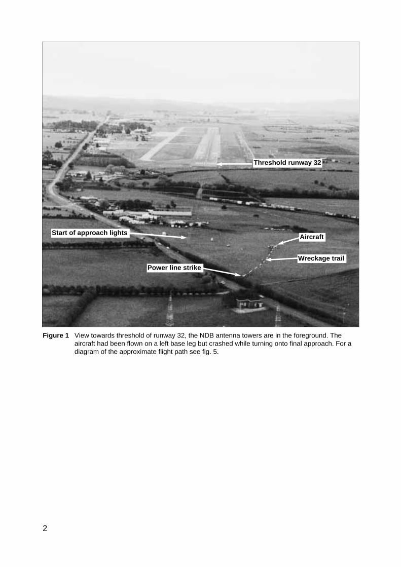
Figure 1 View towards threshold of runway 32, the NDB antenna towers are in the foreground. Theaircraft had been flown on a left base leg but crashed while turning onto final approach. For adiagram of the approximate flight path see fig. 5.
Wreckage trail
Aircraft
Power line strike
Start of approach lights
Threshold runway 32
3
SYNOPSIS
At 1943 hours on Friday, 17 September 1993, a Piper Chieftain PA-31-350 aircraft,registered VH-WGI, crashed while on a night landing approach to Launceston Airport,Tasmania.
VH-WGI was being operated by one pilot and carried nine passengers. Six passengersreceived fatal injuries. The pilot and three passengers sustained serious injuries. The aircraftwas substantially damaged as a result of impact forces and fire.
The accident occurred while the pilot was making a visual circling approach to land onrunway 32 at Launceston. Some low cloud was present and the aircraft passed throughpatches of cloud on the approach. Late on a left base leg the aircraft entered a steep leftbank. Shortly after, at a height of about 200 ft, the aircraft developed a rapid rate of descent.This descent culminated in collision with the ground.
Significant factors in this occurrence included minimal endorsement training and pilotexperience on type, inadequate operator supervision, and pilot decision making adverselyinfluenced by the carriage of noisy, alcohol-affected passengers. Organisational factorsincluded an absence of standards prescribed by the CAA for aircraft type endorsement. Theinvestigation found indications of significant confusion over the interpretation of AIP DAPinstructions on visual circling approaches, particularly at night.
The report concludes with a number of safety recommendations.
1. FACTUAL INFORMATION
1.1 History of the flight
Members of a football club had planned to visit Launceston, travelling by light aircraft. Threeaircraft were needed to carry the group, with all passengers and pilots contributing to the cost ofthe aircraft hire. One of the club members, who was a pilot, organised the required aircraft andadditional pilots for departure from Moorabbin Airport on the afternoon of 17 September 1993.The operator from whom the aircraft were hired, who also employed the organising pilot as aninstructor, arranged for one Piper PA-23 (VH-PAC), a Piper PA-31-310 (VH-NOS) and a PiperPA-31-350 (VH-WGI) to be available for the trip, with the organising pilot to fly VH-WGI.
On the day of the flight the pilot of VH-WGI carried out pre-flight inspections, obtained theweather forecasts and submitted flight plans for all three aircraft. The flight plans for the twoPA-31 aircraft were for flights operated in accordance with IFR procedures. The PA-23 was tooperate in accordance with VFR procedures. The TAF for Launceston predicted 2 octas ofstratocumulus cloud, base 2,000 ft and 3 octas of stratocumulus cloud, base 3,500 ft.
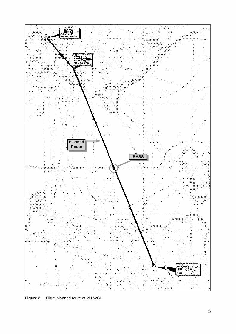
The flight plan for VH-WGI (see fig. 2) indicated that the aircraft would track Moorabbin–Wonthaggi–Bass–Launceston and cruise at an altitude of 9,000 ft. A cruise TAS of 160 kts, totalplan flight time of 90 minutes, endurance 155 minutes and Type of Operation ‘G’ (privatecategory flight) were specified. No alternate aerodrome was nominated and none was required.The estimated time of departure was 1730. The flight plan was submitted to the CAA byfacsimile at 1529. Last light at Launceston was 1919.
VH-WGI departed Moorabbin at 1817 and climbed to an en-route cruise altitude of 9,000 ft.The pilot was required to report at Wonthaggi but passed this position at 1832 withoutreporting. Melbourne ATC tried unsuccessfully to contact the pilot because of this missed
4
report. Later, the Melbourne radar controller noticed the aircraft deviating left of track but wasunable to make contact. Communications were re-established at 1858 when the pilot calledMelbourne FS saying he had experienced a radio problem. By this time the aircraft headinghad been corrected to regain track.
At 1927 the pilot called Launceston Tower and was cleared for a DME arrival along theinbound track of the Launceston VOR 325 radial. The Launceston ATIS indicated 2 octas ofcloud at 800 ft, QNH 1,012 hPa, wind 320° at 5–10 kts, temperature +10° and runway 32 inuse. At 1930 the ADC advised the pilot that the 2 octas of cloud were clear of the inboundtrack, but that there was some lower cloud forming just north of the field, possibly on track.He informed the pilot that there was a chance he might not be visual by the VOR, in whichcase he would need to perform an ILS approach via the Nile locator beacon.
The ADC contacted the airport meteorological observer at 1933, inquiring as to what the 1930searchlight check of cloud height had revealed. He was told the observation indicated 7 octas ofcloud at about 800 ft. At 1935.52 (time in hours, minutes and seconds) the ADC asked the pilotfor his DME (distance) and level. The pilot responded that he was at 12 DME and 3,300 ft. TheADC told the pilot that conditions were deteriorating with probably 4 octas at 800 ft at the field.He then told the pilot he would hopefully get a break in the cloud, but then restated that if hewas not visual by the VOR to make a missed approach, track to Nile and climb to 3,000 ft. At1939.45 the pilot was again asked for his DME and level. He indicated that he was at 1,450 ft and2–3 DME. He then also confirmed that he was still in IMC. There were three other aircraftinbound for Launceston and the ADC made an all-stations broadcast that conditions weredeteriorating at Launceston, with 4 octas at 800 ft, and to expect an ILS approach.
At 1940.56 the pilot stated that he was overhead the field, but did not have it sighted and wasgoing around. At 1941.07 the pilot reported that he had the airfield in sight and at 1941.16 thathe was positioned above the final approach for runway 32. Fifteen seconds later the pilotreported that he was opposite the tower and was advised by the ADC that he was cleared for avisual approach, or a missed approach to Nile as preferred. The pilot indicated he would takethe visual approach and was then told to manoeuvre as preferred for runway 32. This wasacknowledged at 1941.48. No further communications were received from the pilot.
The ADC made a broadcast to two other inbound aircraft at 1942.32, advising that VH-WGIwas in the circuit ahead of them, that it had become visual about half a mile south of the VOR,that it was manoeuvring for a visual approach and was just in and out of the base of the cloud.
After the pilot of VH-WGI reported over the field, and the aircraft first appeared out of cloud,witnesses observed it track to about the south-east end of the aerodrome at a height of about500–800 ft. It then turned left to track north-west on the north-east side of the main runwayand approximately over the grass runway. The aircraft was seen to be travelling at high speed,and passing through small areas of cloud. North of the main terminal building a left turn wasinitiated onto a close downwind leg for runway 32. The aircraft appeared to descend while onthis leg. As the base turn was started, at a height estimated as 300–500 ft, the aircraft brieflywent through cloud. Some of the witnesses reported that the engine noise from the aircraftduring the approach was fairly loud, suggestive of a high power setting.
Late on a left base leg the aircraft was observed to be in a steep left bank, probably in the orderof 60°, at a height of about 200 ft. It then descended rapidly and struck a powerline with theright wing, approximately 28 ft AGL, resulting in an airport electrical power failure at 1943.02.Almost simultaneously the left wing struck bushes. A short distance beyond the powerlines theaircraft struck the ground and slid to a stop. A fierce fire broke out immediately. Airport fireservices responded to the accident and the fire was quickly extinguished. Six of the occupantsreceived fatal injuries and the others, including the pilot, were seriously injured.
5
BASS
PlannedRoute
Figure 2 Flight planned route of VH-WGI.
6
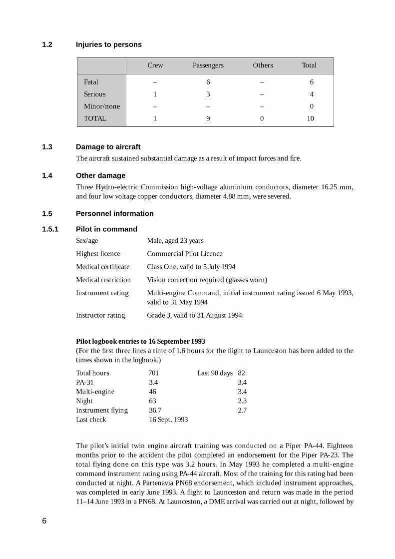
1.2 Injuries to persons
Crew Passengers Others Total
Fatal – 6 – 6
Serious 1 3 – 4
Minor/none – – – 0
TOTAL 1 9 0 10
1.3 Damage to aircraft
The aircraft sustained substantial damage as a result of impact forces and fire.
1.4 Other damage
Three Hydro-electric Commission high-voltage aluminium conductors, diameter 16.25 mm,and four low voltage copper conductors, diameter 4.88 mm, were severed.
1.5 Personnel information
1.5.1 Pilot in command
Sex/age Male, aged 23 years
Highest licence Commercial Pilot Licence
Medical certificate Class One, valid to 5 July 1994
Medical restriction Vision correction required (glasses worn)
Instrument rating Multi-engine Command, initial instrument rating issued 6 May 1993,valid to 31 May 1994
Instructor rating Grade 3, valid to 31 August 1994
Pilot logbook entries to 16 September 1993(For the first three lines a time of 1.6 hours for the flight to Launceston has been added to thetimes shown in the logbook.)
Total hours 701 Last 90 days 82PA-31 3.4 3.4Multi-engine 46 3.4Night 63 2.3Instrument flying 36.7 2.7Last check 16 Sept. 1993
The pilot’s initial twin engine aircraft training was conducted on a Piper PA-44. Eighteenmonths prior to the accident the pilot completed an endorsement for the Piper PA-23. Thetotal flying done on this type was 3.2 hours. In May 1993 he completed a multi-enginecommand instrument rating using PA-44 aircraft. Most of the training for this rating had beenconducted at night. A Partenavia PN68 endorsement, which included instrument approaches,was completed in early June 1993. A flight to Launceston and return was made in the period11–14 June 1993 in a PN68. At Launceston, a DME arrival was carried out at night, followed by
a circling approach for a landing on runway 32. The pilot’s total experience on the PN68 was5.3 hours.
Since then the pilot had logged 2.7 hours of instrument flight in single engine aircraft. Also, 3.4hours accumulated by his students operating a synthetic trainer had been entered by the pilotin his logbook, as simulated instrument flying carried out by him. Part of this synthetic trainertime was in early July 1993. It totalled 2 hours, and was conducted by two students inpreparation for their GFPT. It consisted of straight and level flight, medium level turns, climbsand descents, and stall recognition. Two other synthetic trainer sessions were completed on 6and 13 August 1993 with a student starting his navigation training. These sessions consisted ofADF and VOR orientation.
Under CAO 40.1.0, para. 10.9, the synthetic trainer time on these exercises could not be loggedby the pilot as the students were manipulating the controls. CAO 40.2.1, para. 11.2 specifiesoptions for meeting the minimum experience levels for recency before acting in command onan IFR flight. The instrument flight time recorded by the pilot, which met the requirements forthe logging of instrument flight time, was 2.7 hours. This did not meet the 3-hour minimum.
It is a requirement under CAR 5.52 (1)(c) that time spent practising simulated instrumentflight in an approved synthetic trainer be recorded in the pilot’s logbook. The pilot’s logbookdid not record any instrument approaches during the 90 days prior to the accident. He said hehad conducted a simulated ILS approach in a synthetic trainer in the month before theaccident while working with one of his students. He was unable to state either when or withwhich student this was done, and no pilot or company records could be found to substantiatethe statement.
To meet the ILS approach recent experience requirements stipulated in CAO 40.2.1 the pilotmust have completed at least one such approach within the preceding 35 days. There was a 90-day currency requirement for ADF and VOR. An ILS approach would also have renewed thepilot’s VOR currency and could have been flown in an approved synthetic trainer. The lastrecorded ILS approach in the pilot’s logbook was flown early in June 1993.
On 13 and 16 September 1993 the pilot received type endorsement training on the PA-31-350aircraft. This training consisted of upper air work and circuits, by day, in VH-WGI. The pilotrecorded a total of 1.8 hours in his logbook. Company documents recorded an air switch total(i.e. the time that the aircraft was airborne) of 1.2 hours for the training. No instrumentapproaches, night flying, low-level circuits or maximum weight/aft CG flying were conductedas part of the pilot’s training on the PA-31-350 aircraft. Prior to commencing the flight toLaunceston on 17 September 1993 the pilot had no other experience on PA-31 aircraft.
The pilot stated that in the past he had experienced problems with aircraft navigationinstruments giving unreliable indications, an example of which was an oscillating glide slope.Because of this type of problem he preferred to make a visual approach if he could. There wasno evidence to suggest such an instrument problem existed during the accident flight.
1.5.2 Previous 72 hours history
The pilot worked as an instructor at the operator’s flying school and was rostered off duty fromThursday 16 September to Monday 20 September to provide for the trip to Launceston. OnThursday 16 September he went to the flying school to complete his PA-31 endorsementtraining. He also continued to make arrangements for the flight to Launceston. Because ofcomplications with these arrangements, the pilot did not arrive home until between 2200 and2300. On 17 September he arrived at the school office at about 0830–0900 and spent the dayconcentrating on matters related to the flight to Launceston.
7
8
1.6 Aircraft information
1.6.1 Significant particulars
Registration VH-WGI
Manufacturer Piper Aircraft Corporation
Model PA-31-350
Common name Chieftain
Serial no. 31-7305075
Country of manufacture USA
Year of manufacture 1973
Engines 2 Lycoming TIO-540-J2BD
Engine type Reciprocating
Date of issue of certificate of registration 21 May 1991
Maintenance release No. 211402, issued 11 December 1992 at 8,622 hours and valid to11 December 1993 or 8,722 hours (whichever was attained first)
Total aircraft hours attime of accident 8,712.6
1.6.2 Aircraft history
The aircraft was placed on the Australian Register on 6 May 1974. After several changes ofcertificate holder it was transferred to the present holder on 21 May 1991. For part of the timesince then it was operated in New Zealand.
The last periodic inspection was carried out at Moorabbin Airport and a maintenance releasewas issued on 11 December 1992. Three ADs were not called up on the current maintenancerelease at the time of issue. However, one was subsequently completed prior to the accidentand the other two had no effect on the operation of the aircraft during the accident flight.
There were two outstanding entries on the maintenance release. These had been entered on 16January 1993. Although the entries had not been signed off, documentation was obtained thatindicated maintenance required to render the items serviceable had been completed duringJune and July 1993.
1.6.3 Weight and balance
Maximum permissible take-off weight 3,178 kg
Estimated
– take-off weight (TOW) 3,273 kg
– TOW centre of gravity 3,392 mm aft of datum
– fuel burn taxi, and in flight 151 kg
– accident weight 3,122 kg (weight reduced in flight by fuel burn)
– centre-of-gravity at accident 3,400 mm aft of datum
Centre of gravity limits
– forward 3,200 mm aft of datum at 3,178 kg
3,099 mm aft of datum at 2,815 kg
3,048 mm aft of datum at 2,361 kg or less, with linear variation between2,361 kg, 2,815 kg and 3,178 kg
– rear 3,429 mm aft of datum at all weights
Datum 3,480 mm forward of the main spar centreline
Prior to the flight the pilot completed a loading form to calculate the load and CG position.This incorrectly indicated that the take-off weight was 3,178 kg. The fuel and passenger weightswere underestimated and luggage weight was slightly overestimated. At the time of takeoff theaircraft was approximately 95 kg above the maximum permissible take-off weight. BASIcalculations were made using information from the aircraft flight manual and included databased on full main fuel tanks, luggage weighed at the scene, weight data provided by the pilotand surviving passengers, and passenger post-mortem weights. Although the maximum take-off weight was exceeded, the aircraft was within weight and balance limitations at the time ofthe accident due to the amount of fuel consumed during the flight.
1.7 Meteorological information
1.7.1 Introduction
As the flight was to be operated under IFR, the pilot in command was required to obtain eithera flight forecast for the route being flown, or an ARFOR and a TAF. For ARFORs the heightsgiven for cloud are AMSL, whereas TAFs provide cloud heights above aerodrome elevation.Similarly, aerodrome weather observations as made by either meteorological observers or ATC,and broadcast on the ATIS, also measure cloud heights above the aerodrome elevation.
The planned route from Moorabbin to Launceston was within the area 32 (northern half of theflight) and area 70 (southern half of the flight) forecast regions. Commonly, areas 30/31/32(mainly Victoria) and areas 70/71 (Tasmania) are issued as combined forecasts for therespective areas. At 1354 on 17 September 1993 the pilot received facsimile copies of the area30/31/32 forecast valid from 1330 to 0300, and the area 70/71 forecast valid 1300 to 0300, alongwith an amended area 70/71 forecast valid 1500 to 0300. TAFs were also obtained for Wynyard,Devonport and Launceston, valid from 1200 to 2400. All of these forecasts were recovered fromthe wreckage.
1.7.2 Forecasts
The area 70/71 forecast predicted broken stratus cloud developing after 1800 on the northcoast of Tasmania, with the base at 1,500–2,000 ft; cumulus and stratocumulus cloud withbroken coverage on the north coast and Bass Strait, base 2,500 ft, tops 4,000 ft; and cumulusand stratocumulus cloud with scattered coverage inland, base 2,500 ft, tops 8,000 ft. Isolatedrain was forecast in the north-west and northern areas. The Launceston TAF predicted 2 octasof stratocumulus cloud at 2,000 ft and 3 octas of stratocumulus cloud at 3,500 ft. The forecastsurface wind was 150°T at 10 kts. Visibility was forecast to be 10 km or greater, QNH1,013–1,012 hPa.
An amended TAF for Launceston was issued at 1628, valid from 1800 to 0600. This predictedthe surface wind as variable at 5 kts, visibility 10 km or greater, drizzle, 2 octas ofstratocumulus at 2,500 ft, 5 octas of stratocumulus at 3,000 ft, QNH 1,011–1,012 hPa. This
9
forecast did not affect the operational planning of the flight.
A later amended TAF was issued at 1932, valid until 0600. This predicted the surface wind of330°T at 5 kts, visibility 10 km or greater, drizzle, 6 octas of stratus at 800 ft, 8 octas ofstratocumulus at 2,000 ft, QNH 1,011–1,012 hPa. At the time of issue of this forecast theaircraft was on descent into Launceston.
1.7.3 Weather conditions at Launceston
In the 1900 Metar the cloud base was reported as 1 octa of stratus at 1,000 ft and 3 octas ofcumulus at 2,000 ft above the aerodrome elevation. The weather conditions were deterioratingas VH-WGI was on descent into Launceston. Observations by the meteorological observer at1930 indicated there were 7 octas of cloud at 800 ft. The ADC separately assessed the cloudcover as 4 octas of cloud at 800 ft. Visibility clear of cloud was good. The pilot later indicatedthat the aircraft did not pass through any rain on the approach. However, during the circlingapproach at the aerodrome the aircraft went through patches of cloud, some of which mayhave been below 800 ft. After the accident the weather deteriorated and some rain/drizzleoccurred. In the 2000 observation the meteorological observer reported the cloud as 7 octas ofstratus at 600 ft.
The observation points for the ADC and the observer were different, with the observer beinglocated about 450 m north-west of the tower. The cloud searchlight, which was used toestablish cloud height, was a further 274.3 m north-west of the observation point. Thesearchlight was a fixed installation which directed a narrow beam of light at an angle of 63° 26’up, towards the south-east.
1.8 Aids to navigation and instrument approaches
1.8.1 Aids to navigation
The aerodrome is equipped with an NDB, a VOR, and a DME. There is also an ILS installed forapproaches to runway 32. A locator beacon (a low-powered NDB), Nile, positioned 13 kmsouth-east of the threshold of runway 32, is an additional tracking aid, primarily for use inconjunction with the ILS approach.
The aids are monitored by ATC and were serviceable at the time of the accident.
1.8.2 Instrument approaches
Instrument approach procedures are published in AIP DAPS. At Launceston, instrumentapproaches are published for runway 14 VOR or VOR/DME, runway 32 ILS (fig. 3) or LLZ,runway 32 VOR/DME, and runway 32 NDB/L. These procedures enable pilots to descend in aprescribed pattern to the MDA/DA for each type of approach at the airport. The DA for the ILSwas lower than for the other approach options.
The runway 32 ILS approach commences from the Nile locator beacon at an altitude of 3,000 ft.The aircraft descends on a 3° glide path, aligned with the extended runway centreline. When 32is the active runway this approach allows the pilot to descend on the ILS glide slope to analtitude of 750 ft, which is a height of 202 ft above the runway threshold. If conditions arevisual at or before this stage the pilot can continue the approach straight ahead to land onrunway 32.
For aircraft approaching the airport from the north-west there is a time penalty in using theILS approach due to the requirement to position the aircraft south-east of the airfield for theapproach from Nile.
Instrument approaches provide for aircraft performance categories based on 1.3 times the stall
10
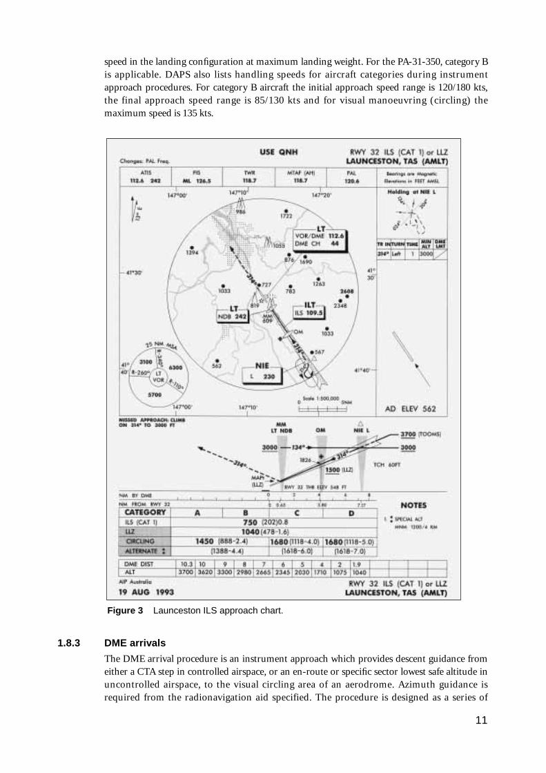
speed in the landing configuration at maximum landing weight. For the PA-31-350, category Bis applicable. DAPS also lists handling speeds for aircraft categories during instrumentapproach procedures. For category B aircraft the initial approach speed range is 120/180 kts,the final approach speed range is 85/130 kts and for visual manoeuvring (circling) themaximum speed is 135 kts.
1.8.3 DME arrivals
The DME arrival procedure is an instrument approach which provides descent guidance fromeither a CTA step in controlled airspace, or an en-route or specific sector lowest safe altitude inuncontrolled airspace, to the visual circling area of an aerodrome. Azimuth guidance isrequired from the radionavigation aid specified. The procedure is designed as a series of
11
Figure 3 Launceston ILS approach chart.
descending steps on particular tracks or within a specified sector. In this case the inbound trackfrom the north-west was not aligned with the runway in use and the pilot was required tomake a visual circling approach to land towards the north-west on runway 32.
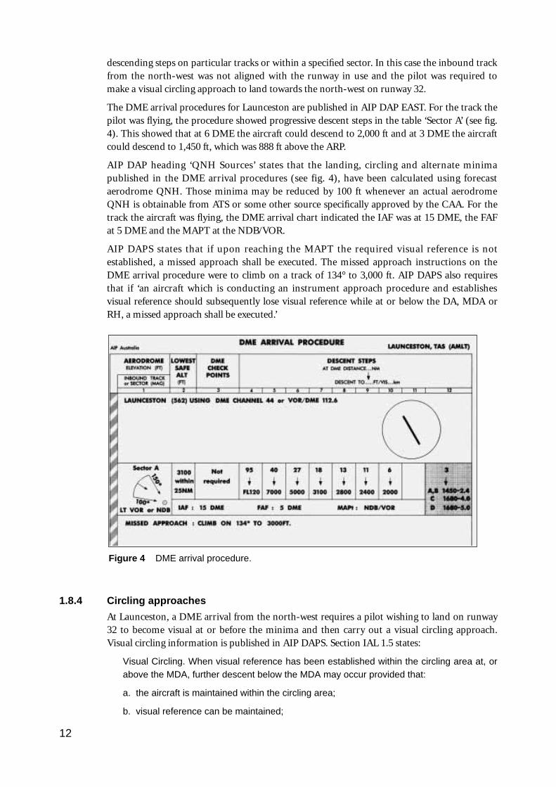
The DME arrival procedures for Launceston are published in AIP DAP EAST. For the track thepilot was flying, the procedure showed progressive descent steps in the table ‘Sector A’ (see fig.4). This showed that at 6 DME the aircraft could descend to 2,000 ft and at 3 DME the aircraftcould descend to 1,450 ft, which was 888 ft above the ARP.
AIP DAP heading ‘QNH Sources’ states that the landing, circling and alternate minimapublished in the DME arrival procedures (see fig. 4), have been calculated using forecastaerodrome QNH. Those minima may be reduced by 100 ft whenever an actual aerodromeQNH is obtainable from ATS or some other source specifically approved by the CAA. For thetrack the aircraft was flying, the DME arrival chart indicated the IAF was at 15 DME, the FAFat 5 DME and the MAPT at the NDB/VOR.
AIP DAPS states that if upon reaching the MAPT the required visual reference is notestablished, a missed approach shall be executed. The missed approach instructions on theDME arrival procedure were to climb on a track of 134° to 3,000 ft. AIP DAPS also requiresthat if ‘an aircraft which is conducting an instrument approach procedure and establishesvisual reference should subsequently lose visual reference while at or below the DA, MDA orRH, a missed approach shall be executed.’
1.8.4 Circling approaches
At Launceston, a DME arrival from the north-west requires a pilot wishing to land on runway32 to become visual at or before the minima and then carry out a visual circling approach.Visual circling information is published in AIP DAPS. Section IAL 1.5 states:
Visual Circling. When visual reference has been established within the circling area at, orabove the MDA, further descent below the MDA may occur provided that:
a. the aircraft is maintained within the circling area;
b. visual reference can be maintained;
12
Figure 4 DME arrival procedure.
c. the approach threshold or approach lights or other markings identifiable with theapproach end of the runway to be used are visible during the subsequent visual flight;and
d. obstacle clearance of at least 300 feet (categories A and B) or 400 feet (categories Cand D) or 500 feet (category E) is maintained along the flight path until the aircraft isaligned with the runway, strip or landing direction to be used.
Note 1 follows this and states:
For the purpose of this paragraph ‘visual reference’ means clear of cloud, in sight ofground or water and with a flight visibility not less than the minimum specified for circling.
The pilot said that in his approach planning he used the spot height of 819 ft as a reference forthe highest terrain, and that he was using an obstacle clearance of 400 ft, which indicated hecould descend to an altitude of 1,220 ft, which was 660 ft above the aerodrome elevation. (Asthe aircraft was category B an obstacle clearance of 300 ft was permitted.) The pilot said thathearing the report of cloud at 800 ft AGL indicated to him that there would not be any cloudbelow this level.
1.9 Communications
The aircraft was equipped with two VHF and one HF radio communication systems. For thisflight the pilot was required to maintain continuous two-way communications.
Shortly after departing Moorabbin the pilot was in contact with Melbourne Radar AdvisoryService and was then transferred to Melbourne Control on 135.3 MHz. The aircrafttemporarily lost two-way communications. For most of the subsequent en-route portion of theflight the aircraft was in uncontrolled airspace and communications were with Melbourne FS.Approaching the Launceston area the pilot was transferred to Melbourne Control at 1919. At1927 he was transferred to Launceston Tower.
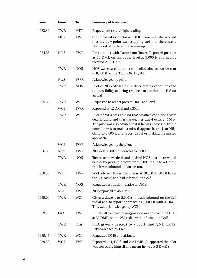
1.9.1 Summary of communications
Time From To Summary of transmission
1927.16 WGI TWR First contact with Launceston Tower. Aircraft at 7,000 ftand 25 DME. Analysis of other DME reports indicatedthe aircraft was probably at 35 DME.
TWR WGI Pilot given a DME arrival to track inbound on the 325radial.
1928.09 SEC 3 TWR Sector 3 and tower coordinate the arrival of VH-NOS,VH-WZI and VH-FKA.
1930.03 TWR WGI Tower confirms that the pilot of WGI has ATIS infor-mation Golf.
TWR WGI Latest actual weather passed to pilot; 2 octas at 800 ftclear of the aircraft inbound track with some lower cloudforming just north of the field, possibly on the aircraftinbound track. The pilot was advised that if he was notvisual by the omni he would need to carry out an ILS viathe Nile locator.
WGI TWR Acknowledged by pilot.
13
Time From To Summary of transmission
1933.39 TWR MET Request latest searchlight reading.
MET TWR Cloud passed as 7 octas at 800 ft. Tower was also advisedthat the dew point was dropping and that there was alikelihood of fog later in the evening.
1934.36 NOS TWR First contact with Launceston Tower. Reported positionas 55 DME on the 326R, level at 9,000 ft and havingreceived ATIS Golf.
TWR NOS NOS was cleared to enter controlled airspace on descentto 8,000 ft on the 326R. QNH 1,012.
NOS TWR Acknowledged by pilot.
TWR NOS Pilot of NOS advised of the deteriorating conditions andthe possibility of being required to conduct an ILS onarrival.
1935.52 TWR WGI Requested to report present DME and level.
WGI TWR Reported at 12 DME and 3,300 ft.
TWR WGI Pilot of WGI was advised that weather conditions weredeteriorating and that the weather was 4 octas at 800 ft.The pilot was also advised that if he was not visual by theomni he was to make a missed approach, track to Nile,climb to 3,000 ft and report visual or making the missedapproach.
WGI TWR Acknowledged by the pilot.
1936.33 NOS TWR NOS left 9,000 ft on descent to 8,000 ft.
TWR NOS Tower acknowledged and advised NOS that there wouldbe a delay prior to descent from 8,000 ft due to a Dash 8which was inbound to Launceston.
1938.36 WZI TWR WZI advised Tower that it was at 10,000 ft, 30 DME onthe 320 radial and had information Golf.
TWR NOS Requested a position relative to DME.
NOS TWR NOS reported at 45 DME.
1939.00 TWR WZI Given a descent to 5,000 ft to track inbound on the 320radial and to report approaching 5,000 ft with a DME.This was acknowledged by WZI.
1939.18 FKA TWR Initial call to Tower giving position as approaching FL110at 32 DME, on the 289 radial with information Golf.
TWR FKA FKA given a descent to 7,000 ft and QNH 1,012.Acknowledged by FKA.
1939.45 TWR WGI Requested DME and altitude.
1939.50 WGI TWR Reported at 1,450 ft and 2–3 DME. (It appeared the pilotwas correcting himself and meant he was at 3 DME.)
14
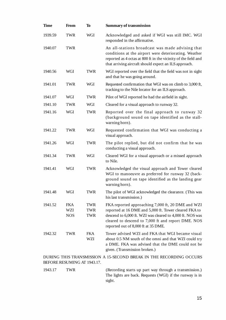
Time From To Summary of transmission
1939.59 TWR WGI Acknowledged and asked if WGI was still IMC. WGIresponded in the affirmative.
1940.07 TWR An all-stations broadcast was made advising thatconditions at the airport were deteriorating. Weatherreported as 4 octas at 800 ft in the vicinity of the field andthat arriving aircraft should expect an ILS approach.
1940.56 WGI TWR WGI reported over the field that the field was not in sightand that he was going around.
1941.01 TWR WGI Requested confirmation that WGI was on climb to 3,000 ft,tracking to the Nile locator for an ILS approach.
1941.07 WGI TWR Pilot of WGI reported he had the airfield in sight.
1941.10 TWR WGI Cleared for a visual approach to runway 32.
1941.16 WGI TWR Reported over the final approach to runway 32(background sound on tape identified as the stall-warning horn).
1941.22 TWR WGI Requested confirmation that WGI was conducting avisual approach.
1941.26 WGI TWR The pilot replied, but did not confirm that he wasconducting a visual approach.
1941.34 TWR WGI Cleared WGI for a visual approach or a missed approachto Nile.
1941.41 WGI TWR Acknowledged the visual approach and Tower clearedWGI to manoeuvre as preferred for runway 32 (back-ground sound on tape identified as the landing gearwarning horn).
1941.48 WGI TWR The pilot of WGI acknowledged the clearance. (This washis last transmission.)
1941.52 FKA TWR FKA reported approaching 7,000 ft, 20 DME and WZIWZI TWR reported at 16 DME and 5,000 ft. Tower cleared FKA toNOS TWR descend to 6,000 ft. WZI was cleared to 4,000 ft. NOS was
cleared to descend to 7,000 ft and report DME. NOSreported out of 8,000 ft at 35 DME.
1942.32 TWR FKA Tower advised WZI and FKA that WGI became visualWZI about 0.5 NM south of the omni and that WZI could try
a DME. FKA was advised that the DME could not begiven. (Transmission broken.)
DURING THIS TRANSMISSION A 15-SECOND BREAK IN THE RECORDING OCCURSBEFORE RESUMING AT 1943.17.
1943.17 TWR (Recording starts up part way through a transmission.)The lights are back. Requests (WGI) if the runway is insight.
15
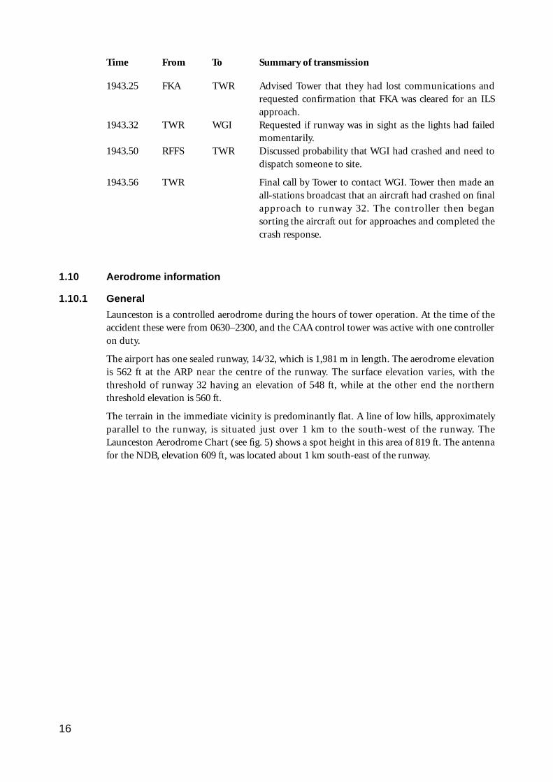
Time From To Summary of transmission
1943.25 FKA TWR Advised Tower that they had lost communications andrequested confirmation that FKA was cleared for an ILSapproach.
1943.32 TWR WGI Requested if runway was in sight as the lights had failedmomentarily.
1943.50 RFFS TWR Discussed probability that WGI had crashed and need todispatch someone to site.
1943.56 TWR Final call by Tower to contact WGI. Tower then made anall-stations broadcast that an aircraft had crashed on finalapproach to runway 32. The controller then begansorting the aircraft out for approaches and completed thecrash response.
1.10 Aerodrome information
1.10.1 General
Launceston is a controlled aerodrome during the hours of tower operation. At the time of theaccident these were from 0630–2300, and the CAA control tower was active with one controlleron duty.
The airport has one sealed runway, 14/32, which is 1,981 m in length. The aerodrome elevationis 562 ft at the ARP near the centre of the runway. The surface elevation varies, with thethreshold of runway 32 having an elevation of 548 ft, while at the other end the northernthreshold elevation is 560 ft.
The terrain in the immediate vicinity is predominantly flat. A line of low hills, approximatelyparallel to the runway, is situated just over 1 km to the south-west of the runway. TheLaunceston Aerodrome Chart (see fig. 5) shows a spot height in this area of 819 ft. The antennafor the NDB, elevation 609 ft, was located about 1 km south-east of the runway.
16
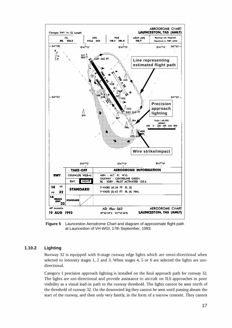
1.10.2 Lighting
Runway 32 is equipped with 6-stage runway edge lights which are omni-directional whenselected to intensity stages 1, 2 and 3. When stages 4, 5 or 6 are selected the lights are uni-directional.
Category 1 precision approach lighting is installed on the final approach path for runway 32.The lights are uni-directional and provide assistance to aircraft on ILS approaches in poorvisibility as a visual lead-in path to the runway threshold. The lights cannot be seen north ofthe threshold of runway 32. On the downwind leg they cannot be seen until passing abeam thestart of the runway, and then only very faintly, in the form of a narrow crescent. They cannot
17
Figure 5 Launceston Aerodrome Chart and diagram of approximate flight pathat Launceston of VH-WGI, 17th September, 1993.
Line representingestimated flight path
Wire strike/impact
Precisionapproachlighting
be fully seen until an aircraft is well into a normal base-leg position, and even then the level oflight intensity is relatively low in comparison to the appearance of the lights when on or closeto final approach. They also have six stages of light intensity settings. The layout of theseapproach lights forms a distinctive pattern which is considerably different in appearance to therunway lighting layout.
Runway 32 is also equipped with a T-Vasis. This is for use by aircraft on final approach and isdesigned to be visible within 7.5° either side of the runway centreline for a distance of 5 NMfrom the runway threshold. By T-Vasis reference a pilot can obtain a visual indication ofwhether the aircraft is on the correct glide slope, or too high or low. There are six stages ofintensity settings for the T-Vasis.
At the time the aircraft was approaching to land, the intensity settings for the runway,approach and T-Vasis were set at stage 2. Three other aircraft landed shortly after the accidentand none reported any problems with the aerodrome lighting.
The aerodrome was equipped with two illuminated wind indicators and an operatingaerodrome beacon was positioned on the control tower.
1.10.3 Other lighting
Several buildings on the airport complex had external lighting switched on. Outside the airportboundary there are lights on buildings near the approach path for runway 32. Also, adistinctive line of lights on an east-west section of a railway line crosses the approach lightpattern in a straight line.
The town of Evandale is 3 km south-east of the airport and the town of Perth is 4 km west-south-west of the threshold of runway 32. There are houses on the line of low hills parallel torunway 32 just over 1 km south-west of the airport. The surrounding area is mainly openfarmland and it was possible that farm house lights and vehicle lights could have beenilluminated. The pilot said he did not see any lights outside the runway/aerodrome complexduring the approach.
1.11 Flight recorders/GPWS
The aircraft was not equipped with a FDR, a CVR, or a GPWS, nor was it required to be.
1.12 Wreckage and impact information
1.12.1 Accident site description
The accident site (see fig. 6) was located on a property adjacent to the Evandale Road,Launceston, Tasmania. The main body of the wreckage was situated about 900 m from thethreshold of runway 32, on a bearing of 138°. It lay in the middle of a relatively flat grass fieldwhich was free of any trees or other obstacles. The geographic coordinates of the accident sitewere: latitude 41°33.5’S, longitude 147°13.3’E.
18
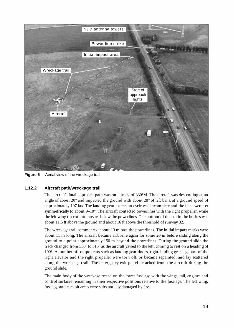
1.12.2 Aircraft path/wreckage trail
The aircraft’s final approach path was on a track of 330°M. The aircraft was descending at anangle of about 20° and impacted the ground with about 28° of left bank at a ground speed ofapproximately 107 kts. The landing gear extension cycle was incomplete and the flaps were setsymmetrically to about 9–10°. The aircraft contacted powerlines with the right propeller, whilethe left wing tip cut into bushes below the powerlines. The bottom of the cut in the bushes wasabout 11.5 ft above the ground and about 16 ft above the threshold of runway 32.
The wreckage trail commenced about 13 m past the powerlines. The initial impact marks wereabout 11 m long. The aircraft became airborne again for some 20 m before sliding along theground to a point approximately 150 m beyond the powerlines. During the ground slide thetrack changed from 330° to 315° as the aircraft yawed to the left, coming to rest on a heading of190°. A number of components such as landing gear doors, right landing gear leg, part of theright elevator and the right propeller were torn off, or became separated, and lay scatteredalong the wreckage trail. The emergency exit panel detached from the aircraft during theground slide.
The main body of the wreckage rested on the lower fuselage with the wings, tail, engines andcontrol surfaces remaining in their respective positions relative to the fuselage. The left wing,fuselage and cockpit areas were substantially damaged by fire.
19
NDB antenna towers
Power line strike
Initial impact area
Wreckage trail
Start ofapproach
lights
Figure 6 Aerial view of the wreckage trail.
Aircraft
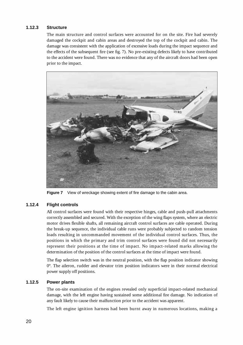
1.12.3 Structure
The main structure and control surfaces were accounted for on the site. Fire had severelydamaged the cockpit and cabin areas and destroyed the top of the cockpit and cabin. Thedamage was consistent with the application of excessive loads during the impact sequence andthe effects of the subsequent fire (see fig. 7). No pre-existing defects likely to have contributedto the accident were found. There was no evidence that any of the aircraft doors had been openprior to the impact.
1.12.4 Flight controls
All control surfaces were found with their respective hinges, cable and push-pull attachmentscorrectly assembled and secured. With the exception of the wing flaps system, where an electricmotor drives flexible shafts, all remaining aircraft control surfaces are cable operated. Duringthe break-up sequence, the individual cable runs were probably subjected to random tensionloads resulting in uncommanded movement of the individual control surfaces. Thus, thepositions in which the primary and trim control surfaces were found did not necessarilyrepresent their positions at the time of impact. No impact-related marks allowing thedetermination of the position of the control surfaces at the time of impact were found.
The flap selection switch was in the neutral position, with the flap position indicator showing0°. The aileron, rudder and elevator trim position indicators were in their normal electricalpower supply off positions.
1.12.5 Power plants
The on-site examination of the engines revealed only superficial impact-related mechanicaldamage, with the left engine having sustained some additional fire damage. No indication ofany fault likely to cause their malfunction prior to the accident was apparent.
The left engine ignition harness had been burnt away in numerous locations, making a
20
Figure 7 View of wreckage showing extent of fire damage to the cabin area.
comprehensive examination impossible. Examination of the magneto remains found allcomponents within the manufacturer’s limits. The turbocharger compressor shaft was rotatedwith some difficulty, consistent with it having been subjected to fire.
During the wreckage examination the engine throttle levers were found in about the mid-rangeposition, the left lever being slightly more advanced. Both mixture levers were in the mid-rangesetting. With the exception of the manifold pressure gauge, where the left pointer was at 28inches Hg and the right at 29 inches Hg, the remaining engine instrument indicators wereeither on zero or, due to fire damage, gave no discernible information.
Both engines were removed for further examination to determine their pre-impact status. Allmechanical and fire-damaged components essential to the engine operation were replaced.Other non-essential components such as the turbocharger and the hydraulic and vacuumpumps, were disconnected. Both engines were test run and found to be capable of normaloperation, with performance parameters being within the manufacturer’s limits.
1.12.6 Propellers
The right propeller had separated from the engine; the left propeller remained attached to theengine. The blades on both propellers sustained different degrees of deformation and their tipscontained deep round marks, some of which exhibited arcing and local metal melting,indicating contact with an electrical conductor. The right propeller blade pre-load plates eachcontained an indentation consistent with the pitch pin’s separation. The location of theindentation was almost identical on all blades and was consistent with the blades having beenin the fine pitch range at that time. The left propeller had latches locked with the pitch changerod flats indicating that the blades were in fine pitch at impact.
Neither propeller’s internal working components exhibited pre-existing damage or anyabnormality likely to have affected the propeller’s function. Imprints of the pre-load plates onthe matching hub faces indicated that the blades had been driven under power.
The right propeller pitch lever was in about a mid-range setting and the left lever was advancedtowards the fine pitch setting.
1.12.7 Landing gear and hydraulic power
The landing gear extension cycle is initiated by moving the selector handle to the downposition. The sequence first initiates unlocking and opening of the doors followed byunlocking of the gear. After the gear has moved to the full down position, the sequencecontinues with closure of the main landing gear inboard doors. On their full closure, the build-up of hydraulic pressure in a delay valve returns the handle to the down-neutral positionindicating to the pilot, together with three green landing lights, that the extension cycle hasbeen successfully completed. The landing gear extension cycle is completed in approximately5–7 seconds.
The gear selector handle was found in the down position, and the main landing gear inboarddoors were found to have been torn off in the early stages of the impact sequence. Examinationof the landing gear, doors and their mechanisms found nothing which might have interferedwith their normal function. The emergency extension handle was in the stowed position.
1.12.8 Fuel system
The aircraft fuel system has a capacity of 730 litres. It consists of independent left and rightsystems interconnected by a cross-feed valve located on the left side of the aircraft. Each systemconsists of inboard and outboard fuel tanks, a fuel filter, a fuel tank selector, electric boost fuelpumps and a shut-off valve.
21
A quantity of fuel was present in the right-wing main tank (the left-wing tanks were destroyedby fire). A sample was tested and met the required specifications. Both systems’ shut-off andcross-feed valves were closed, and both selector valve main tank ports were closed. Theauxiliary tank ports were partially opened. The fuel filters were clear. All fuel pumps were freeof faults and capable of normal operation.
The valve positions did not correspond with the positions of the fuel selector panel controllevers. The fuel selector panel levers were in positions consistent with a configuration of shut-off valves open, both systems on main tanks, and cross-feed valve open. In the impact sequencethe fuselage lower surface was significantly deformed. The impact forces resulted in randomloads being applied to the cables connecting the valves with the control levers and changedtheir original relative positions.
1.12.9 Instruments
Only a small number of cockpit instruments were recovered for examination, most havingbeen badly damaged by fire. Nothing was found to preclude their normal operation. Marks onthe left altimeter indicated that it read 570 ft at the time of impact; its pressure subscale was setat 1,010 hPa. The right altimeter pressure sub-scale was also set to 1,010 hPa. Most of theinstruments provided no meaningful information.
1.12.10 Remaining systems
Due to the extent of fire damage it was not possible to determine the pre-impact status of theheat and ventilation, pitot-static and electrical systems. However, examination of the recoveredcomponents found no fault likely to have affected their normal operation.
1.12.11 Maintenance history
A review of the aircraft, engine and propeller logbooks found nothing suggesting anyirregularity likely to have affected the airworthiness of the aircraft.
1.13 Medical and pathological information
1.13.1 Post-mortem examinations
Post-mortem examinations were conducted on all the deceased passengers. None of themreceived fatal injuries in the accident impact sequence. All died from fire effects. Toxicologicalanalysis did not reveal the presence of any drugs other than alcohol. Blood alcohol levelsranged from 0.041 to 0.218. Urine alcohol samples showed generally similar but slightly higherresults.
1.13.2 Alcohol levels/passenger behaviour
The blood alcohol results for the fatally injured persons were provided by the TasmanianGovernment Analyst Laboratory. The blood alcohol concentration is expressed as a percentageof milligrams of alcohol in each millilitre of blood. By reference to seat numbers the post-mortem blood alcohol and urine alcohol analysis results were as follows:
Seat 2 Ba 0.131 Ua 0.183
Seat 3 Ba 0.207 Ua 0.290
Seat 4 Ba 0.104 Ua 0.156
Seat 6 Ba 0.041 Ua 0.062
Seat 8 Ba 0.055 Ua 0.085
Seat 10 Ba 0.218 Ua 0.283
22
The pilot voluntarily gave a blood sample at about 0020 on 18 September 1994. No alcohol wasdetected in this specimen. No blood alcohol samples were obtained from the three seriouslyinjured passengers.
Small levels of carbon monoxide were found in four of the fatally injured passengers. Specialistmedical opinion obtained by the Bureau was that the amount was insignificant.
VH-WGI was expected to be available for departure at 1600, but was not obtained until after1700. VH-NOS was also not obtained until much later than expected. Passengers and well-wishers started arriving at the school at about 1430. The pilot of VH-NOS and the pilot of VH-PAC told the pilot of VH-WGI they only wanted to carry passengers who were not noisy. Inresponse they were told there weren’t any, but that the pilot of VH-WGI would carry the noisiest.
Some of the passengers remained inside the school building during the long wait for departure.Others stayed outside, kicking a football nearby, looking at aircraft parked in front of thebuilding or simply passing the time while waiting to leave. Behaviour varied betweenindividuals but some were noisy and boisterous. The attention of the pilot of VH-NOS wasdrawn to two noisy passengers who were consuming alcohol inside the school building. Hetold them he would not take them on his aircraft due to their alcohol-affected state. These twopassengers later travelled to Launceston in VH-WGI.
An observer later reported seeing the passengers at the time of loading, some with cans of beerin hand, moving back and forwards between the two PA-31 aircraft. People were getting in andout of the aircraft and luggage was being put in the wing lockers and then taken out again. Thiswas accompanied by occasional loud voices. The CP, although not rostered for duty, had beenat the operator’s premises during the day. He later went out to VH-WGI during the loading fordeparture and gave the pilot advice on where to seat the heavier passengers. The CP said thatonce the passengers were finally seated in VH-WGI he had given them a briefing.
The pilot in command is required by CAR 256 (1) to ensure that a person in a state ofintoxication does not enter the aircraft. It is probable that some of the passengers wereintoxicated at the time of loading. A practical difficulty in interpreting this requirement is inassessing whether persons are intoxicated. Alcohol was carried onto VH-WGI for the flight toLaunceston and consumed while the aircraft was en route. Toilet facilities were not available onthe aircraft. During the flight some of the passengers used bags to hold their urine.
During the flight the passengers were noisy and the pilot said he was constantly interrupted bypassenger questions. While making the circling approach he was interrupted by questions fromthe passenger in the front right hand seat and the pilot told him clearly he was unhappy with theinterruptions. When interviewed in hospital following the accident the pilot’s first comment,which was in relation to passenger behaviour, was to the effect that ‘it was a pig of a trip.’
None of the survivors could recall the final moments of the flight.
1.14 Fire
The fire appeared to have been started by sparks accompanying the aircraft battery separationigniting fuel spilled from the ruptured wing or engine fuel lines. An intense fire broke outalmost instantly. The fire was extinguished by the airport fire service approximately six minutesafter the impact.
No evidence of in-flight fire was found.
23
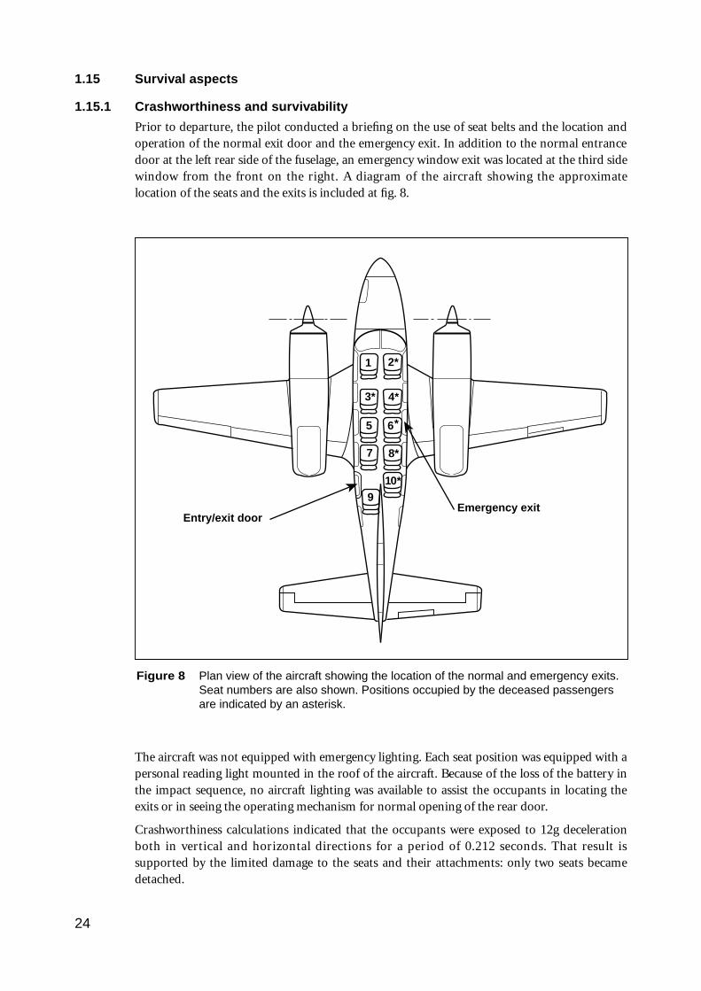
1.15 Survival aspects
1.15.1 Crashworthiness and survivability
Prior to departure, the pilot conducted a briefing on the use of seat belts and the location andoperation of the normal exit door and the emergency exit. In addition to the normal entrancedoor at the left rear side of the fuselage, an emergency window exit was located at the third sidewindow from the front on the right. A diagram of the aircraft showing the approximatelocation of the seats and the exits is included at fig. 8.
The aircraft was not equipped with emergency lighting. Each seat position was equipped with apersonal reading light mounted in the roof of the aircraft. Because of the loss of the battery inthe impact sequence, no aircraft lighting was available to assist the occupants in locating theexits or in seeing the operating mechanism for normal opening of the rear door.
Crashworthiness calculations indicated that the occupants were exposed to 12g decelerationboth in vertical and horizontal directions for a period of 0.212 seconds. That result issupported by the limited damage to the seats and their attachments: only two seats becamedetached.
24
Figure 8 Plan view of the aircraft showing the location of the normal and emergency exits.Seat numbers are also shown. Positions occupied by the deceased passengersare indicated by an asterisk.
1
3*
5
7
2*
4*
6
8*
910*
Emergency exitEntry/exit door
*
The limited deformation of the aircraft cabin left the occupants with survivable space. Theemergency exit on the right side and a number of windows popped out during the impactsequence. The main door was found open on site.
Two passengers exited through the left main door. The pilot and one passenger exited throughthe right emergency exit.
1.15.2 Emergency services response
A total electrical power failure occurred at the aerodrome when the aircraft struck thepowerlines. This caused a failure of the runway and approach lighting together with the controltower lighting and communication equipment. Emergency power restored all lighting andcommunications after 15 seconds. A fireman on duty in the fire control tower saw electricalarcing as the aircraft struck the powerlines. Three fire vehicles were dispatched to the scene. At1948.48 fire vehicle ‘Tender One’ reported that it had located the aircraft. Using foam, theRFFS extinguished the fire almost immediately.
The common crash call facility connected the ADC only to the airport fire service, the civil fireservice and the hospital. It was therefore necessary for the tower controller to contact thepolice, ambulance and CAA SAR service by making separate phone calls. Another person wasvisiting the tower when the accident occurred and was able to assist with the phone calls. Anambulance was requested at 1949. It arrived at approximately 2002.
1.16 CAA/operator/industry
1.16.1 CAA responsibilities
The functions of the CAA are specified in Part II Section 9 of the Civil Aviation Act 1988. Inpart, Section 9 (1) states that the function of the Authority, as provided by the Act andregulations, is to conduct safety regulation of civil air operations in Australian territory. Anumber of other functions are also described.
At the time of the accident, safety regulation of civil air operations fell within the responsibilityof the Safety Regulation and Standards (SR&S) Division of the CAA.
The stated vision of SR&S was ‘A safe and viable industry’.
The CAA SR&S district office responsible for the operator was located at Moorabbin Airport.In the 2.5 months since the operator had opened for business, the assigned FOI had visited theorganisation at least three times. These visits included a discussion at the request of theoperator, made shortly after he commenced operations, to ascertain whether companyprocedures were satisfactory. Other visits were to assess the standard of training and testingconducted by the operator.
(a) Aircraft endorsement requirements
CAO 40.1.0, issue 5, commencement date 4 April 1993, refers to aircraft endorsements—aeroplanes. This CAO refers to two kinds of endorsement, a ‘type endorsement’ and a ‘classendorsement.’ In this case a type endorsement was given.
Para. 6.1 (a) of this CAO, in relation to a type endorsement, states that the person seeking anendorsement must:
(i) hold a student pilot licence or an aeroplane pilot licence; and
(ii) undertake training in operating limitations, procedures and systems on the type ofaeroplane for which the endorsement is sought; and
25
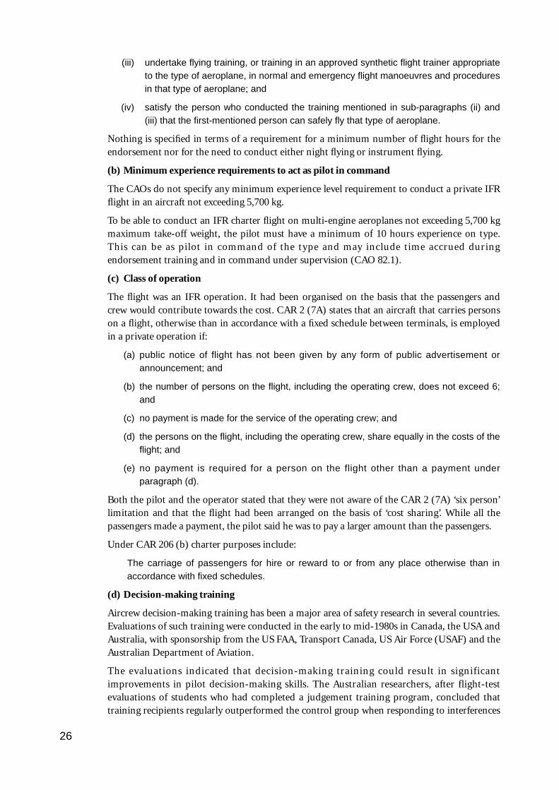
(iii) undertake flying training, or training in an approved synthetic flight trainer appropriateto the type of aeroplane, in normal and emergency flight manoeuvres and proceduresin that type of aeroplane; and
(iv) satisfy the person who conducted the training mentioned in sub-paragraphs (ii) and(iii) that the first-mentioned person can safely fly that type of aeroplane.
Nothing is specified in terms of a requirement for a minimum number of flight hours for theendorsement nor for the need to conduct either night flying or instrument flying.
(b) Minimum experience requirements to act as pilot in command
The CAOs do not specify any minimum experience level requirement to conduct a private IFRflight in an aircraft not exceeding 5,700 kg.
To be able to conduct an IFR charter flight on multi-engine aeroplanes not exceeding 5,700 kgmaximum take-off weight, the pilot must have a minimum of 10 hours experience on type.This can be as pilot in command of the type and may include time accrued duringendorsement training and in command under supervision (CAO 82.1).
(c) Class of operation
The flight was an IFR operation. It had been organised on the basis that the passengers andcrew would contribute towards the cost. CAR 2 (7A) states that an aircraft that carries personson a flight, otherwise than in accordance with a fixed schedule between terminals, is employedin a private operation if:
(a) public notice of flight has not been given by any form of public advertisement orannouncement; and
(b) the number of persons on the flight, including the operating crew, does not exceed 6;and
(c) no payment is made for the service of the operating crew; and
(d) the persons on the flight, including the operating crew, share equally in the costs of theflight; and
(e) no payment is required for a person on the flight other than a payment underparagraph (d).
Both the pilot and the operator stated that they were not aware of the CAR 2 (7A) ‘six person’limitation and that the flight had been arranged on the basis of ‘cost sharing’. While all thepassengers made a payment, the pilot said he was to pay a larger amount than the passengers.
Under CAR 206 (b) charter purposes include:
The carriage of passengers for hire or reward to or from any place otherwise than inaccordance with fixed schedules.
(d) Decision-making training
Aircrew decision-making training has been a major area of safety research in several countries.Evaluations of such training were conducted in the early to mid-1980s in Canada, the USA andAustralia, with sponsorship from the US FAA, Transport Canada, US Air Force (USAF) and theAustralian Department of Aviation.
The evaluations indicated that decision-making training could result in significantimprovements in pilot decision-making skills. The Australian researchers, after flight-testevaluations of students who had completed a judgement training program, concluded thattraining recipients regularly outperformed the control group when responding to interferences
26
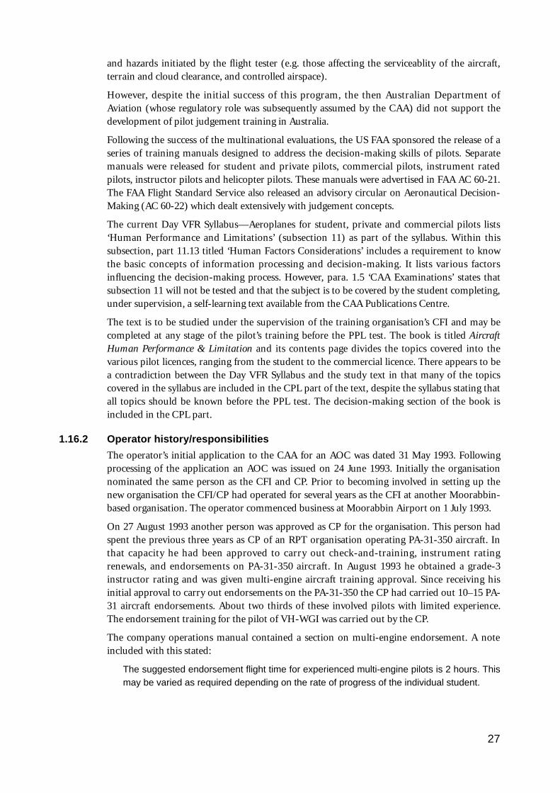
and hazards initiated by the flight tester (e.g. those affecting the serviceablity of the aircraft,terrain and cloud clearance, and controlled airspace).
However, despite the initial success of this program, the then Australian Department ofAviation (whose regulatory role was subsequently assumed by the CAA) did not support thedevelopment of pilot judgement training in Australia.
Following the success of the multinational evaluations, the US FAA sponsored the release of aseries of training manuals designed to address the decision-making skills of pilots. Separatemanuals were released for student and private pilots, commercial pilots, instrument ratedpilots, instructor pilots and helicopter pilots. These manuals were advertised in FAA AC 60-21.The FAA Flight Standard Service also released an advisory circular on Aeronautical Decision-Making (AC 60-22) which dealt extensively with judgement concepts.
The current Day VFR Syllabus—Aeroplanes for student, private and commercial pilots lists‘Human Performance and Limitations’ (subsection 11) as part of the syllabus. Within thissubsection, part 11.13 titled ‘Human Factors Considerations’ includes a requirement to knowthe basic concepts of information processing and decision-making. It lists various factorsinfluencing the decision-making process. However, para. 1.5 ‘CAA Examinations’ states thatsubsection 11 will not be tested and that the subject is to be covered by the student completing,under supervision, a self-learning text available from the CAA Publications Centre.
The text is to be studied under the supervision of the training organisation’s CFI and may becompleted at any stage of the pilot’s training before the PPL test. The book is titled AircraftHuman Performance & Limitation and its contents page divides the topics covered into thevarious pilot licences, ranging from the student to the commercial licence. There appears to bea contradiction between the Day VFR Syllabus and the study text in that many of the topicscovered in the syllabus are included in the CPL part of the text, despite the syllabus stating thatall topics should be known before the PPL test. The decision-making section of the book isincluded in the CPL part.
1.16.2 Operator history/responsibilities
The operator’s initial application to the CAA for an AOC was dated 31 May 1993. Followingprocessing of the application an AOC was issued on 24 June 1993. Initially the organisationnominated the same person as the CFI and CP. Prior to becoming involved in setting up thenew organisation the CFI/CP had operated for several years as the CFI at another Moorabbin-based organisation. The operator commenced business at Moorabbin Airport on 1 July 1993.
On 27 August 1993 another person was approved as CP for the organisation. This person hadspent the previous three years as CP of an RPT organisation operating PA-31-350 aircraft. Inthat capacity he had been approved to carry out check-and-training, instrument ratingrenewals, and endorsements on PA-31-350 aircraft. In August 1993 he obtained a grade-3instructor rating and was given multi-engine aircraft training approval. Since receiving hisinitial approval to carry out endorsements on the PA-31-350 the CP had carried out 10–15 PA-31 aircraft endorsements. About two thirds of these involved pilots with limited experience.The endorsement training for the pilot of VH-WGI was carried out by the CP.
The company operations manual contained a section on multi-engine endorsement. A noteincluded with this stated:
The suggested endorsement flight time for experienced multi-engine pilots is 2 hours. Thismay be varied as required depending on the rate of progress of the individual student.
27
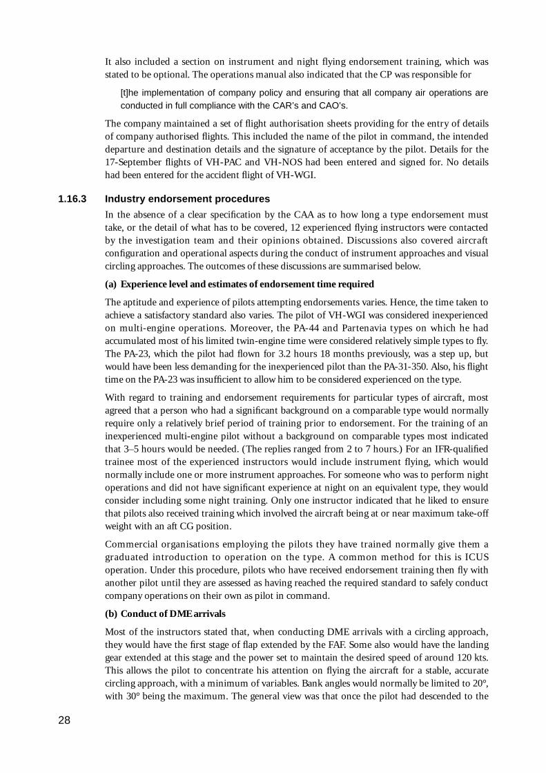
It also included a section on instrument and night flying endorsement training, which wasstated to be optional. The operations manual also indicated that the CP was responsible for
[t]he implementation of company policy and ensuring that all company air operations areconducted in full compliance with the CAR’s and CAO’s.
The company maintained a set of flight authorisation sheets providing for the entry of detailsof company authorised flights. This included the name of the pilot in command, the intendeddeparture and destination details and the signature of acceptance by the pilot. Details for the17-September flights of VH-PAC and VH-NOS had been entered and signed for. No detailshad been entered for the accident flight of VH-WGI.
1.16.3 Industry endorsement procedures
In the absence of a clear specification by the CAA as to how long a type endorsement musttake, or the detail of what has to be covered, 12 experienced flying instructors were contactedby the investigation team and their opinions obtained. Discussions also covered aircraftconfiguration and operational aspects during the conduct of instrument approaches and visualcircling approaches. The outcomes of these discussions are summarised below.
(a) Experience level and estimates of endorsement time required
The aptitude and experience of pilots attempting endorsements varies. Hence, the time taken toachieve a satisfactory standard also varies. The pilot of VH-WGI was considered inexperiencedon multi-engine operations. Moreover, the PA-44 and Partenavia types on which he hadaccumulated most of his limited twin-engine time were considered relatively simple types to fly.The PA-23, which the pilot had flown for 3.2 hours 18 months previously, was a step up, butwould have been less demanding for the inexperienced pilot than the PA-31-350. Also, his flighttime on the PA-23 was insufficient to allow him to be considered experienced on the type.
With regard to training and endorsement requirements for particular types of aircraft, mostagreed that a person who had a significant background on a comparable type would normallyrequire only a relatively brief period of training prior to endorsement. For the training of aninexperienced multi-engine pilot without a background on comparable types most indicatedthat 3–5 hours would be needed. (The replies ranged from 2 to 7 hours.) For an IFR-qualifiedtrainee most of the experienced instructors would include instrument flying, which wouldnormally include one or more instrument approaches. For someone who was to perform nightoperations and did not have significant experience at night on an equivalent type, they wouldconsider including some night training. Only one instructor indicated that he liked to ensurethat pilots also received training which involved the aircraft being at or near maximum take-offweight with an aft CG position.
Commercial organisations employing the pilots they have trained normally give them agraduated introduction to operation on the type. A common method for this is ICUSoperation. Under this procedure, pilots who have received endorsement training then fly withanother pilot until they are assessed as having reached the required standard to safely conductcompany operations on their own as pilot in command.
(b) Conduct of DME arrivals
Most of the instructors stated that, when conducting DME arrivals with a circling approach,they would have the first stage of flap extended by the FAF. Some also would have the landinggear extended at this stage and the power set to maintain the desired speed of around 120 kts.This allows the pilot to concentrate his attention on flying the aircraft for a stable, accuratecircling approach, with a minimum of variables. Bank angles would normally be limited to 20°,with 30° being the maximum. The general view was that once the pilot had descended to the
28
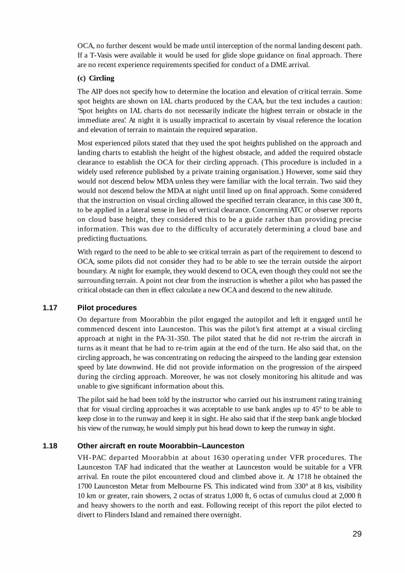
OCA, no further descent would be made until interception of the normal landing descent path.If a T-Vasis were available it would be used for glide slope guidance on final approach. Thereare no recent experience requirements specified for conduct of a DME arrival.
(c) Circling
The AIP does not specify how to determine the location and elevation of critical terrain. Somespot heights are shown on IAL charts produced by the CAA, but the text includes a caution:‘Spot heights on IAL charts do not necessarily indicate the highest terrain or obstacle in theimmediate area’. At night it is usually impractical to ascertain by visual reference the locationand elevation of terrain to maintain the required separation.
Most experienced pilots stated that they used the spot heights published on the approach andlanding charts to establish the height of the highest obstacle, and added the required obstacleclearance to establish the OCA for their circling approach. (This procedure is included in awidely used reference published by a private training organisation.) However, some said theywould not descend below MDA unless they were familiar with the local terrain. Two said theywould not descend below the MDA at night until lined up on final approach. Some consideredthat the instruction on visual circling allowed the specified terrain clearance, in this case 300 ft,to be applied in a lateral sense in lieu of vertical clearance. Concerning ATC or observer reportson cloud base height, they considered this to be a guide rather than providing preciseinformation. This was due to the difficulty of accurately determining a cloud base andpredicting fluctuations.
With regard to the need to be able to see critical terrain as part of the requirement to descend toOCA, some pilots did not consider they had to be able to see the terrain outside the airportboundary. At night for example, they would descend to OCA, even though they could not see thesurrounding terrain. A point not clear from the instruction is whether a pilot who has passed thecritical obstacle can then in effect calculate a new OCA and descend to the new altitude.
1.17 Pilot procedures
On departure from Moorabbin the pilot engaged the autopilot and left it engaged until hecommenced descent into Launceston. This was the pilot’s first attempt at a visual circlingapproach at night in the PA-31-350. The pilot stated that he did not re-trim the aircraft inturns as it meant that he had to re-trim again at the end of the turn. He also said that, on thecircling approach, he was concentrating on reducing the airspeed to the landing gear extensionspeed by late downwind. He did not provide information on the progression of the airspeedduring the circling approach. Moreover, he was not closely monitoring his altitude and wasunable to give significant information about this.
The pilot said he had been told by the instructor who carried out his instrument rating trainingthat for visual circling approaches it was acceptable to use bank angles up to 45° to be able tokeep close in to the runway and keep it in sight. He also said that if the steep bank angle blockedhis view of the runway, he would simply put his head down to keep the runway in sight.
1.18 Other aircraft en route Moorabbin–Launceston
VH-PAC departed Moorabbin at about 1630 operating under VFR procedures. TheLaunceston TAF had indicated that the weather at Launceston would be suitable for a VFRarrival. En route the pilot encountered cloud and climbed above it. At 1718 he obtained the1700 Launceston Metar from Melbourne FS. This indicated wind from 330° at 8 kts, visibility10 km or greater, rain showers, 2 octas of stratus 1,000 ft, 6 octas of cumulus cloud at 2,000 ftand heavy showers to the north and east. Following receipt of this report the pilot elected todivert to Flinders Island and remained there overnight.
29
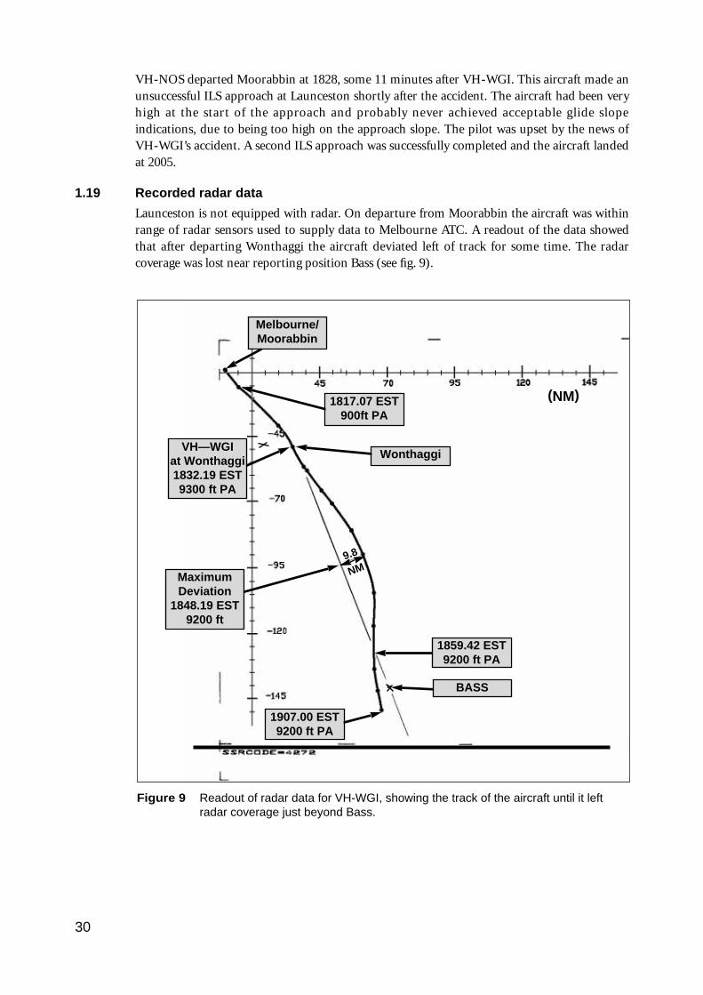
VH-NOS departed Moorabbin at 1828, some 11 minutes after VH-WGI. This aircraft made anunsuccessful ILS approach at Launceston shortly after the accident. The aircraft had been veryhigh at the start of the approach and probably never achieved acceptable glide slopeindications, due to being too high on the approach slope. The pilot was upset by the news ofVH-WGI’s accident. A second ILS approach was successfully completed and the aircraft landedat 2005.
1.19 Recorded radar data
Launceston is not equipped with radar. On departure from Moorabbin the aircraft was withinrange of radar sensors used to supply data to Melbourne ATC. A readout of the data showedthat after departing Wonthaggi the aircraft deviated left of track for some time. The radarcoverage was lost near reporting position Bass (see fig. 9).
30
Figure 9 Readout of radar data for VH-WGI, showing the track of the aircraft until it leftradar coverage just beyond Bass.
MaximumDeviation
1848.19 EST9200 ft
9.8
NM
Melbourne/Moorabbin
1817.07 EST900ft PA
Wonthaggi
1859.42 EST9200 ft PA
1907.00 EST9200 ft PA
BASS
(NM)
VH—WGIat Wonthaggi1832.19 EST9300 ft PA
1.20 Visual illusions/vision obstruction
Some pilots operating into Launceston reported that on approach to runway 32 they hadexperienced an illusion of being higher than they actually were. Others who had operated therefor many years said they had not noticed any such effect.
Banking the aircraft steeply may result in the view to the left from the left seat being partly oralmost completely blocked by the cabin roof line. Given the same distance from the runway,this becomes more pronounced at lower heights. Also, when the aircraft is at a low height onbase leg, the difference between the visual angle from the cockpit to the runway and the angleat ground level is small. Thus, with the limited ability of the eye to detect small changes, thetask of the pilot becomes fairly difficult in terms of detecting small changes in altitude. Thesensing of small altitude changes is made more difficult if there are limited visual cuesavailable.
1.21 ATS-related matters
Although peripheral to the accident a number of ATS-related issues were identified during theinvestigation.
The ADC reported that the Airport Emergency Procedures Manual was cumbersome anddifficult to read, and that no emergency response quick-reference checklist was available.
The ADC received post-incident stress counselling after the accident. However, he stated thathe had not received any pre-incident counselling in his training. It appears that most con-trollers receive information about emergency situations such as accidents through the passingon of peer group knowledge.
The tower cab overhead lighting system illuminated only the console area. As part of theemergency response, the controller was required to use items situated away from this overheadlight source. Such items included the telephone and telephone books. There was a telephonekeypad situated on the console. However, controllers suggested that they did not like to use thisas it utilises the Ericaphon handset. This handset is normally used for operationalcommunications. Controllers stated that when it is used for the external telephone conversationsit can prove distracting and confusing, especially during critical, high-stress situations.
During the power failure air-ground communications ceased. This was due to the loss of boththe primary and secondary air-ground communications systems. A tertiary system linked tothe SPS was available. The SPS is a battery fed power supply which activates when the normalsupply fails. The tertiary communication system is activated manually by the controllerphysically selecting a switch on his console. It remains on line until power is regained fromeither the normal supply or the emergency generator. However, the controller must identifythat power has been lost and then activate the switch. On this occasion the controller did notselect the tertiary system. Even if he had done so, the time spent identifying the problem andthen activating the system would have reduced its effectiveness. Communications returnedwhen the emergency generator began supplying power 15 seconds after the main power failure.
The AVR did not record for approximately 15 seconds after the power failed. It was notconnected to the SPS and was without power from the time of the aircraft’s collision with thepowerlines until the emergency generator came on line.
1.22 Tests and research
1.22.1 Flight test
During the investigation an experienced PA-31 pilot/flight operations inspector indicated thatPA-31-350 handling characteristics may have been a factor contributing to the accident. To
31
explore this aspect, three test flights were carried out using the services of an experienced testpilot. The test aircraft was a Piper PA-31-350. For purposes of comparison it was flown in botha light and a heavily loaded state. This was done in an attempt to simulate closely both theweight and CG situations during the pilot’s endorsement training (light weight forward CG)and at the time of the accident (heavy weight aft CG) flight.
Pertinent results were as follows:
(a) Longitudinal stability was assessed with the aircraft at lighter weights, to simulate theloading at the time of the endorsement training and at the accident weight and CGposition. To conduct this test the aircraft was flown with the landing gear and flap up, withspeed starting at 170 kts and reducing to 110 kts. The aircraft was trimmed to removecontrol forces at the start of the run. As the speed reduced, the elevator control forces wereheld manually and measured using a calibrated spring balance. A similar test wasconducted at the accident weight in the circling configuration with the landing gear up, 10°of flap set, and speed reducing from 140 kts to 100 kts
This test showed that the elevator control forces on the heavy aft CG aircraft were muchless than those of the light aircraft. This change was brought about by the CG on the heavyaircraft being much further aft than that on the lightly loaded aircraft.
The test pilot concluded that with the two CG positions used, considerably more pilotingattention was required to control the aircraft in pitch in the cruise and circlingconfiguration with the CG in the aft (accident) position.
(b) A test (at aft CG) was conducted to ascertain the elevator control force and engine powerrequired to maintain altitude in a turn with increasing bank angle. Indicated airspeed wasmaintained at 120 kts and engine RPM was 2,300. Starting with the elevator loads trimmedout, 22 inches of manifold pressure at zero bank angle, the aircraft was progressively rolledto 45° of bank and the additional elevator control forces held manually. It was necessary toincrease MAP to just over 29 inches to maintain speed and altitude at a 45° bank angle.This indicated that if MAP was not increased in a level steep turn the speed could beexpected to decrease. The required elevator control force to maintain altitude at 45° ofbank was approximately 5.2 kg.
(c) Tests were conducted to assess the aircraft handling qualities at and near the stall inturning flight, at about the accident AUW and CG. This was initially done with wings level,where no unusual handling problems were detected, and then at 30° angle of left bank.Stall warning was found to be adequate. In the wings-level situation, the stall wasaccompanied by a slight left-wing drop. In turning flight (i.e. 30° bank) the manoeuvringcharacteristics at the aft (approximate accident) CG position caused the aircraft to ‘tuck’into the stall as the maximum angle of attack (near stall situation) was approached. Heightloss accompanied the stalls, the extent depending on the stage at which recovery wasinitiated.
Consideration was given to examining the stall characteristics for 45° and 60° of bank. Becauseof observed changes in handling characteristics between 0° and 30° angle of bank, the risk ofrestrained ballast moving, post-stall bank angles exceeding 90°, and the aircraft beingoverstressed, this manoeuvre was considered unsafe and was not carried out.
1.22.2 Audio tape monitor/analysis
In the recording of the radio transmission from the pilot at 1941.16 in which he reported beingover the final approach for runway 32 as he commenced the circling approach, a backgroundsound could be heard. Analysis of this transmission identified this sound as the stall warning
32
horn operating. The flight manual indicated that the stall warning system operated at a speedof 4–9 kts above the stall.
A further sound was heard in the transmission from the pilot at 1941.48. This was identified asthe landing gear warning horn operating. This horn is intended to operate when at least one ofthe throttle levers is retarded to a position of 12 inches of MAP or less with the landing gear up.However, the CP advised that the horn setting was inaccurate and operated at a setting of17–18 inches of MAP.
Analysis of the recording of transmissions made during the time the pilot was conducting thecircling approach revealed, in some transmissions, background sounds indicative of noiseactivity from the passengers.
1.22.3 Assessment of bank angles at night
At night, the only distinguishing features normally seen by a person viewing an aircraft are thelights displayed. The aircraft was equipped with red and green wing tip and white tailnavigation lights, a rotating beacon and strobe lights. The navigation lights were on. The strobelights were not on. While the rotating beacon probably was on, some witnesses were unsurewhether this was so.
With increasing distance it becomes impractical to reliably estimate aircraft bank angles atnight. Conversely, provided the aircraft is not too far away and the general position anddirection of travel of the aircraft are kept in mind, it is possible to visually estimate the bankangle when at least two of its navigation lights can be seen. Where the aircraft is significantlybanked, and its relative position is such that both wing lights can be seen, a reasonable estimatecan be made. At the time the aircraft was on late base leg, where it was reported to be at a steepbank angle, the red and green navigation lights could both be seen by witnesses.
1.22.4 Flight path on the circling approach
Information was obtained from the communications transcript and witnesses on the aircraftflight path during the circling approach. A reconstruction flight was also flown at Launcestonwith some of these witnesses observing. Opinions of witnesses varied on the precise flight paththe aircraft followed, hence only a general estimate can be made of its flight path (see fig. 5).
33
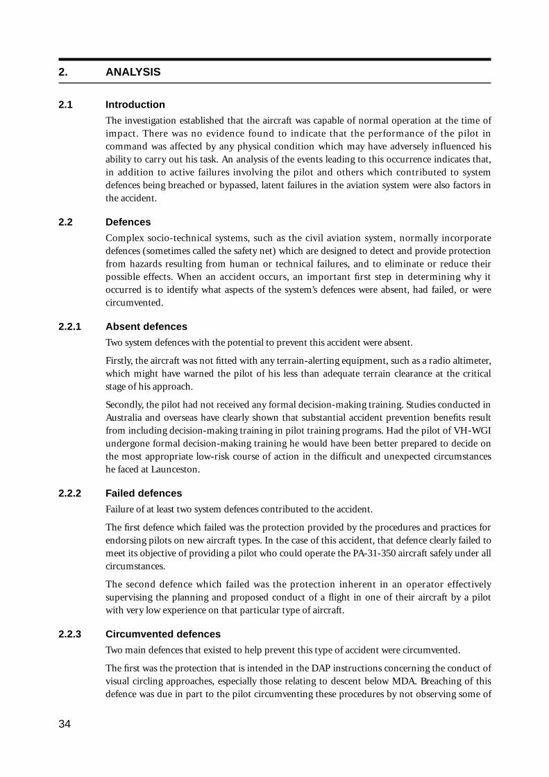
2. ANALYSIS
2.1 Introduction
The investigation established that the aircraft was capable of normal operation at the time ofimpact. There was no evidence found to indicate that the performance of the pilot incommand was affected by any physical condition which may have adversely influenced hisability to carry out his task. An analysis of the events leading to this occurrence indicates that,in addition to active failures involving the pilot and others which contributed to systemdefences being breached or bypassed, latent failures in the aviation system were also factors inthe accident.
2.2 Defences
Complex socio-technical systems, such as the civil aviation system, normally incorporatedefences (sometimes called the safety net) which are designed to detect and provide protectionfrom hazards resulting from human or technical failures, and to eliminate or reduce theirpossible effects. When an accident occurs, an important first step in determining why itoccurred is to identify what aspects of the system’s defences were absent, had failed, or werecircumvented.
2.2.1 Absent defences
Two system defences with the potential to prevent this accident were absent.
Firstly, the aircraft was not fitted with any terrain-alerting equipment, such as a radio altimeter,which might have warned the pilot of his less than adequate terrain clearance at the criticalstage of his approach.
Secondly, the pilot had not received any formal decision-making training. Studies conducted inAustralia and overseas have clearly shown that substantial accident prevention benefits resultfrom including decision-making training in pilot training programs. Had the pilot of VH-WGIundergone formal decision-making training he would have been better prepared to decide onthe most appropriate low-risk course of action in the difficult and unexpected circumstanceshe faced at Launceston.
2.2.2 Failed defences
Failure of at least two system defences contributed to the accident.
The first defence which failed was the protection provided by the procedures and practices forendorsing pilots on new aircraft types. In the case of this accident, that defence clearly failed tomeet its objective of providing a pilot who could operate the PA-31-350 aircraft safely under allcircumstances.
The second defence which failed was the protection inherent in an operator effectivelysupervising the planning and proposed conduct of a flight in one of their aircraft by a pilotwith very low experience on that particular type of aircraft.
2.2.3 Circumvented defences
Two main defences that existed to help prevent this type of accident were circumvented.
The first was the protection that is intended in the DAP instructions concerning the conduct ofvisual circling approaches, especially those relating to descent below MDA. Breaching of thisdefence was due in part to the pilot circumventing these procedures by not observing some of
34
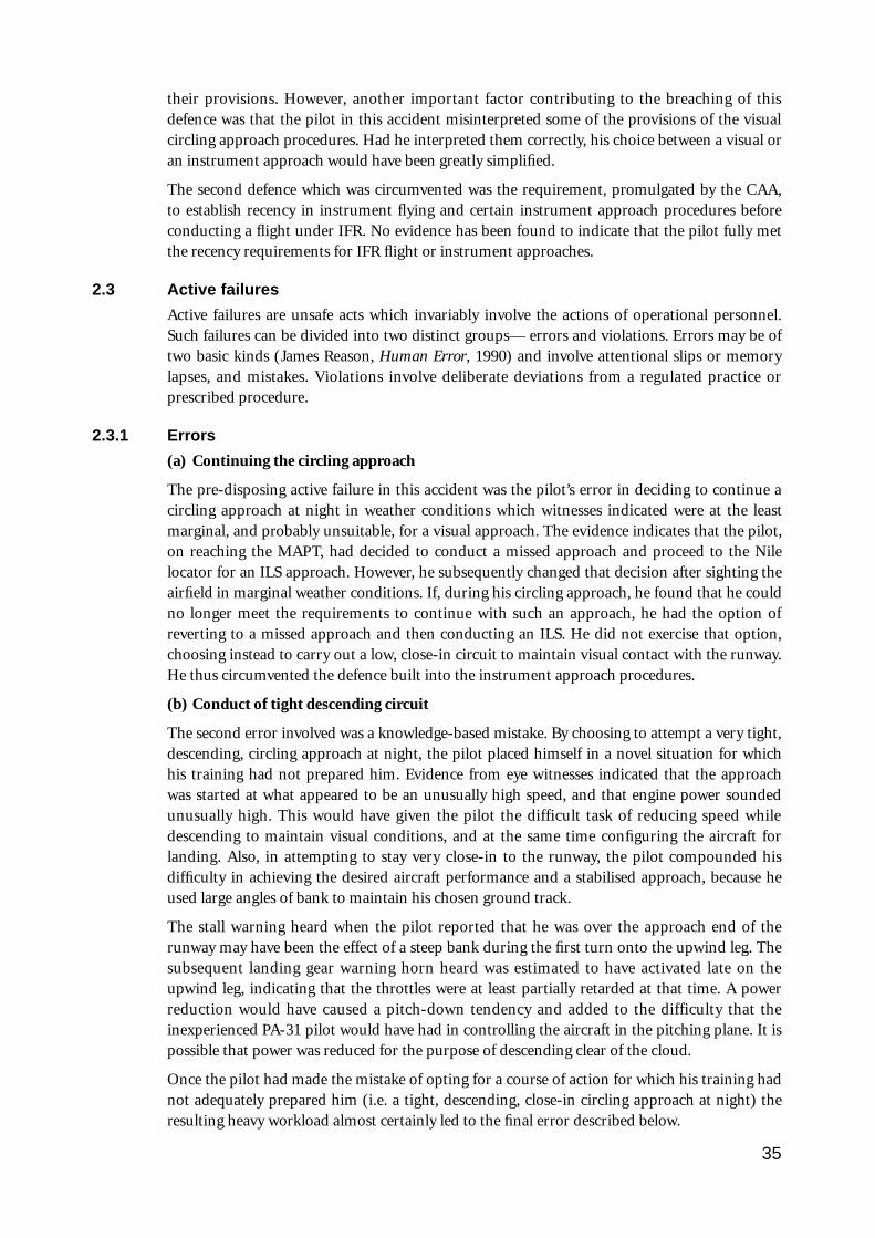
their provisions. However, another important factor contributing to the breaching of thisdefence was that the pilot in this accident misinterpreted some of the provisions of the visualcircling approach procedures. Had he interpreted them correctly, his choice between a visual oran instrument approach would have been greatly simplified.
The second defence which was circumvented was the requirement, promulgated by the CAA,to establish recency in instrument flying and certain instrument approach procedures beforeconducting a flight under IFR. No evidence has been found to indicate that the pilot fully metthe recency requirements for IFR flight or instrument approaches.
2.3 Active failures
Active failures are unsafe acts which invariably involve the actions of operational personnel.Such failures can be divided into two distinct groups— errors and violations. Errors may be oftwo basic kinds (James Reason, Human Error, 1990) and involve attentional slips or memorylapses, and mistakes. Violations involve deliberate deviations from a regulated practice orprescribed procedure.
2.3.1 Errors
(a) Continuing the circling approach
The pre-disposing active failure in this accident was the pilot’s error in deciding to continue acircling approach at night in weather conditions which witnesses indicated were at the leastmarginal, and probably unsuitable, for a visual approach. The evidence indicates that the pilot,on reaching the MAPT, had decided to conduct a missed approach and proceed to the Nilelocator for an ILS approach. However, he subsequently changed that decision after sighting theairfield in marginal weather conditions. If, during his circling approach, he found that he couldno longer meet the requirements to continue with such an approach, he had the option ofreverting to a missed approach and then conducting an ILS. He did not exercise that option,choosing instead to carry out a low, close-in circuit to maintain visual contact with the runway.He thus circumvented the defence built into the instrument approach procedures.
(b) Conduct of tight descending circuit
The second error involved was a knowledge-based mistake. By choosing to attempt a very tight,descending, circling approach at night, the pilot placed himself in a novel situation for whichhis training had not prepared him. Evidence from eye witnesses indicated that the approachwas started at what appeared to be an unusually high speed, and that engine power soundedunusually high. This would have given the pilot the difficult task of reducing speed whiledescending to maintain visual conditions, and at the same time configuring the aircraft forlanding. Also, in attempting to stay very close-in to the runway, the pilot compounded hisdifficulty in achieving the desired aircraft performance and a stabilised approach, because heused large angles of bank to maintain his chosen ground track.
The stall warning heard when the pilot reported that he was over the approach end of therunway may have been the effect of a steep bank during the first turn onto the upwind leg. Thesubsequent landing gear warning horn heard was estimated to have activated late on theupwind leg, indicating that the throttles were at least partially retarded at that time. A powerreduction would have caused a pitch-down tendency and added to the difficulty that theinexperienced PA-31 pilot would have had in controlling the aircraft in the pitching plane. It ispossible that power was reduced for the purpose of descending clear of the cloud.
Once the pilot had made the mistake of opting for a course of action for which his training hadnot adequately prepared him (i.e. a tight, descending, close-in circling approach at night) theresulting heavy workload almost certainly led to the final error described below.
35
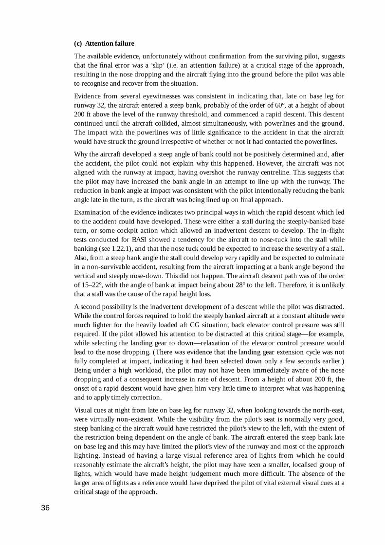
(c) Attention failure
The available evidence, unfortunately without confirmation from the surviving pilot, suggeststhat the final error was a ‘slip’ (i.e. an attention failure) at a critical stage of the approach,resulting in the nose dropping and the aircraft flying into the ground before the pilot was ableto recognise and recover from the situation.
Evidence from several eyewitnesses was consistent in indicating that, late on base leg forrunway 32, the aircraft entered a steep bank, probably of the order of 60°, at a height of about200 ft above the level of the runway threshold, and commenced a rapid descent. This descentcontinued until the aircraft collided, almost simultaneously, with powerlines and the ground.The impact with the powerlines was of little significance to the accident in that the aircraftwould have struck the ground irrespective of whether or not it had contacted the powerlines.
Why the aircraft developed a steep angle of bank could not be positively determined and, afterthe accident, the pilot could not explain why this happened. However, the aircraft was notaligned with the runway at impact, having overshot the runway centreline. This suggests thatthe pilot may have increased the bank angle in an attempt to line up with the runway. Thereduction in bank angle at impact was consistent with the pilot intentionally reducing the bankangle late in the turn, as the aircraft was being lined up on final approach.
Examination of the evidence indicates two principal ways in which the rapid descent which ledto the accident could have developed. These were either a stall during the steeply-banked baseturn, or some cockpit action which allowed an inadvertent descent to develop. The in-flighttests conducted for BASI showed a tendency for the aircraft to nose-tuck into the stall whilebanking (see 1.22.1), and that the nose tuck could be expected to increase the severity of a stall.Also, from a steep bank angle the stall could develop very rapidly and be expected to culminatein a non-survivable accident, resulting from the aircraft impacting at a bank angle beyond thevertical and steeply nose-down. This did not happen. The aircraft descent path was of the orderof 15–22°, with the angle of bank at impact being about 28° to the left. Therefore, it is unlikelythat a stall was the cause of the rapid height loss.
A second possibility is the inadvertent development of a descent while the pilot was distracted.While the control forces required to hold the steeply banked aircraft at a constant altitude weremuch lighter for the heavily loaded aft CG situation, back elevator control pressure was stillrequired. If the pilot allowed his attention to be distracted at this critical stage—for example,while selecting the landing gear to down—relaxation of the elevator control pressure wouldlead to the nose dropping. (There was evidence that the landing gear extension cycle was notfully completed at impact, indicating it had been selected down only a few seconds earlier.)Being under a high workload, the pilot may not have been immediately aware of the nosedropping and of a consequent increase in rate of descent. From a height of about 200 ft, theonset of a rapid descent would have given him very little time to interpret what was happeningand to apply timely correction.
Visual cues at night from late on base leg for runway 32, when looking towards the north-east,were virtually non-existent. While the visibility from the pilot’s seat is normally very good,steep banking of the aircraft would have restricted the pilot’s view to the left, with the extent ofthe restriction being dependent on the angle of bank. The aircraft entered the steep bank lateon base leg and this may have limited the pilot’s view of the runway and most of the approachlighting. Instead of having a large visual reference area of lights from which he couldreasonably estimate the aircraft’s height, the pilot may have seen a smaller, localised group oflights, which would have made height judgement much more difficult. The absence of thelarger area of lights as a reference would have deprived the pilot of vital external visual cues at acritical stage of the approach.
36
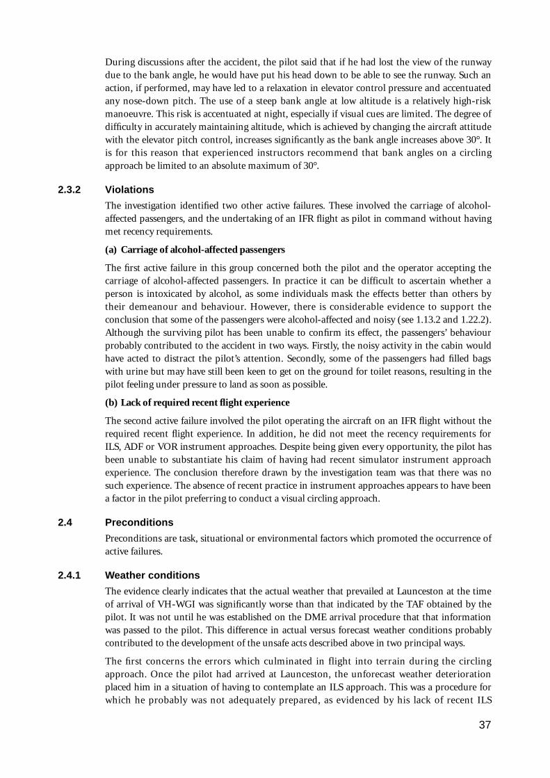
During discussions after the accident, the pilot said that if he had lost the view of the runwaydue to the bank angle, he would have put his head down to be able to see the runway. Such anaction, if performed, may have led to a relaxation in elevator control pressure and accentuatedany nose-down pitch. The use of a steep bank angle at low altitude is a relatively high-riskmanoeuvre. This risk is accentuated at night, especially if visual cues are limited. The degree ofdifficulty in accurately maintaining altitude, which is achieved by changing the aircraft attitudewith the elevator pitch control, increases significantly as the bank angle increases above 30°. Itis for this reason that experienced instructors recommend that bank angles on a circlingapproach be limited to an absolute maximum of 30°.
2.3.2 Violations
The investigation identified two other active failures. These involved the carriage of alcohol-affected passengers, and the undertaking of an IFR flight as pilot in command without havingmet recency requirements.
(a) Carriage of alcohol-affected passengers
The first active failure in this group concerned both the pilot and the operator accepting thecarriage of alcohol-affected passengers. In practice it can be difficult to ascertain whether aperson is intoxicated by alcohol, as some individuals mask the effects better than others bytheir demeanour and behaviour. However, there is considerable evidence to support theconclusion that some of the passengers were alcohol-affected and noisy (see 1.13.2 and 1.22.2).Although the surviving pilot has been unable to confirm its effect, the passengers’ behaviourprobably contributed to the accident in two ways. Firstly, the noisy activity in the cabin wouldhave acted to distract the pilot’s attention. Secondly, some of the passengers had filled bagswith urine but may have still been keen to get on the ground for toilet reasons, resulting in thepilot feeling under pressure to land as soon as possible.
(b) Lack of required recent flight experience
The second active failure involved the pilot operating the aircraft on an IFR flight without therequired recent flight experience. In addition, he did not meet the recency requirements forILS, ADF or VOR instrument approaches. Despite being given every opportunity, the pilot hasbeen unable to substantiate his claim of having had recent simulator instrument approachexperience. The conclusion therefore drawn by the investigation team was that there was nosuch experience. The absence of recent practice in instrument approaches appears to have beena factor in the pilot preferring to conduct a visual circling approach.
2.4 Preconditions
Preconditions are task, situational or environmental factors which promoted the occurrence ofactive failures.
2.4.1 Weather conditions
The evidence clearly indicates that the actual weather that prevailed at Launceston at the timeof arrival of VH-WGI was significantly worse than that indicated by the TAF obtained by thepilot. It was not until he was established on the DME arrival procedure that that informationwas passed to the pilot. This difference in actual versus forecast weather conditions probablycontributed to the development of the unsafe acts described above in two principal ways.
The first concerns the errors which culminated in flight into terrain during the circlingapproach. Once the pilot had arrived at Launceston, the unforecast weather deteriorationplaced him in a situation of having to contemplate an ILS approach. This was a procedure forwhich he probably was not adequately prepared, as evidenced by his lack of recent ILS
37
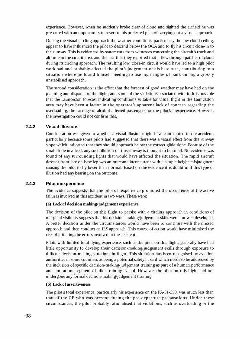
experience. However, when he suddenly broke clear of cloud and sighted the airfield he waspresented with an opportunity to revert to his preferred plan of carrying out a visual approach.
During the visual circling approach the weather conditions, particularly the low cloud ceiling,appear to have influenced the pilot to descend below the OCA and to fly his circuit close-in tothe runway. This is evidenced by statements from witnesses concerning the aircraft’s track andaltitude in the circuit area, and the fact that they reported that it flew through patches of cloudduring its circling approach. The resulting low, close-in circuit would have led to a high pilotworkload and probably affected the pilot’s judgement of his base turn, contributing to asituation where he found himself needing to use high angles of bank during a grosslyunstabilised approach.
The second consideration is the effect that the forecast of good weather may have had on theplanning and dispatch of the flight, and some of the violations associated with it. It is possiblethat the Launceston forecast indicating conditions suitable for visual flight in the Launcestonarea may have been a factor in the operator’s apparent lack of concern regarding theoverloading, the carriage of alcohol-affected passengers, or the pilot’s inexperience. However,the investigation could not confirm this.
2.4.2 Visual illusions
Consideration was given to whether a visual illusion might have contributed to the accident,particularly because some pilots had suggested that there was a visual effect from the runwayslope which indicated that they should approach below the correct glide slope. Because of thesmall slope involved, any such illusion on this runway is thought to be small. No evidence wasfound of any surrounding lights that would have affected the situation. The rapid aircraftdescent from late on base leg was an outcome inconsistent with a simple height misjudgmentcausing the pilot to fly lower than normal. Based on the evidence it is doubtful if this type ofillusion had any bearing on the outcome.
2.4.3 Pilot inexperience
The evidence suggests that the pilot’s inexperience promoted the occurrence of the activefailures involved in this accident in two ways. These were:
(a) Lack of decision making/judgement experience
The decision of the pilot on this flight to persist with a circling approach in conditions ofmarginal visibility suggests that his decision-making/judgement skills were not well developed.A better decision under the circumstances would have been to continue with the missedapproach and then conduct an ILS approach. This course of action would have minimised therisk of initiating the errors involved in the accident.
Pilots with limited total flying experience, such as the pilot on this flight, generally have hadlittle opportunity to develop their decision-making/judgement skills through exposure todifficult decision-making situations in flight. This situation has been recognised by aviationauthorities in some countries as being a potential safety hazard which needs to be addressed bythe inclusion of specific decision-making/judgement training as part of a human performanceand limitations segment of pilot training syllabi. However, the pilot on this flight had notundergone any formal decision-making/judgement training.
(b) Lack of assertiveness
The pilot’s total experience, particularly his experience on the PA-31-350, was much less thanthat of the CP who was present during the pre-departure preparations. Under thesecircumstances, the pilot probably rationalised that violations, such as overloading or the
38

carriage of alcohol-affected passengers, were acceptable because the CP had not commented onthese matters and, with his experience, ‘should know’. Had the pilot been more experienced, hemay have been less influenced by the presence of the CP and displayed the necessaryassertiveness required of a pilot in command. In particular, he may have established bettercontrol of the passengers, pre-departure, with the objective of limiting their alcoholconsumption. Had he done so, he probably would have avoided the in-flight pressures whichmay have influenced his decision to try to land the aircraft as quickly as possible.
2.4.4 Instructions or procedures
In conducting the circling approach in the way he did, the pilot was using a common industryinterpretation of the DAP instructions on circling approaches to calculate OCA. However, afterstarting the circling approach, he abandoned the OCA he had calculated. Instead, he descendedlower, apparently for the purpose of trying to maintain visual reference with the runway lights.This was despite having no assurance of being able to maintain the necessary visual contactwith terrain along his flight path to maintain the required obstacle clearance.
This pilot, and other experienced pilots interviewed during this investigation, demonstratedthat the DAP instructions on visual circling approaches were commonly being misinterpreted.If the DAP instructions had been clearer, particularly with regard to better explaining theobstacle clearance provisions, this pilot’s understanding of options available to him wouldprobably also have been clearer.
Had this pilot correctly interpreted DAP instructions, his decision task would have beensimplified. The only option open to him once he found that he had to descend below MDA toremain below the cloud base, particularly after he began passing through patches of cloud,would have been to initiate a missed approach and position the aircraft for a furtherinstrument approach.
2.4.5 Unfamiliarity with task/high workload
A circling approach at low altitude, at night, in conditions of marginal visibility, is one of themost difficult flying tasks, and requires a high degree of concentration. At night the circuit isflown by reference to external visual cues such as the runway lights and markings identifiablewith the approach end of the runway, to confirm that the desired position of the aircraftrelative to the runway is being maintained, and by reference to the flight instruments. At thelow heights generally involved there is little time to detect and correct any altitude errors beforecollision with terrain occurs. Particular attention must therefore be given to the altimeterduring the instrument scan. Airspeed must also be monitored. Vital actions, such as carryingout checks and lowering the landing gear and flaps, all add to the workload. For an experiencedpilot, current on the type, this may not be a major problem. For an inexperienced pilot onwhat is for him/her a moderately difficult type of aircraft to fly, it probably would be.
With experience on a particular aircraft type, pilots become familiar with its handlingcharacteristics, appropriate configuration for the phase of flight and procedures for the type.This familiarity has the effect of providing the pilot with more time to concentrate on othercritical matters such as aircraft orientation, as he/she does not have to be constantly checkingand adjusting power settings and aircraft attitude to achieve a desired performance.Experienced pilots also adopt procedural methods to minimise workload during a circlingapproach, e.g. selecting the landing gear down early (to remove one potentially distracting taskfrom the high workload segment) and using a pre-determined, constant reference speed (tominimise the attention that must be devoted to power and attitude changes).
In the case of the accident flight, the pilot was operating an aircraft of a significantly greater
39
weight and higher performance than those which he normally flew, or in which he hadconducted the majority of his limited multi-engine flying. His brief endorsement training onthe PA-31-350 did not encompass instrument flying, night flying or low-level circlingapproaches. Moreover, the pilot had conducted very few circling approaches in any aircraft.
Consequently, he was conducting an approach with which he was not familiar, in an aircraftwith which he also had very limited familiarity (i.e. 1.2 hours flight time during his endorse-ment training, plus the time on this flight). Also, because most of the flight to Launceston wasflown with the auto-pilot engaged, he had little opportunity to become familiar with the feel ofa heavily loaded aircraft. Therefore, once the pilot began hand-flying the aircraft for theapproach, the task would have demanded a high level of concentration and would haveresulted in him experiencing a very high workload. This workload could be expected to haveincreased even further when the pilot encountered conditions which forced him to make rapiddecisions and probably to modify the aircraft’s flight path from that with which he was familiarin order to maintain visual contact with the runway.
Although ground witness perceptions of aircraft travelling through cloud can be deceptive, theinformation obtained from witnesses suggested that the aircraft may have entered cloud duringthe visual approach segment more often than the 2–3 times suggested by the pilot. A difficultywith flying at night, particularly on a dark night, is that cloud generally cannot be seen by thepilot until it is entered. Unexpectedly entering cloud would have caused the pilot concern,further adding to his workload, and probably encouraged him to reduce height and remainclose to the runway. The evidence indicated that the pilot descended below the OCA he hadcalculated. This may have been associated with attempts to remain clear of cloud, consistentwith his intention of making a visual approach. The high power and high speed mentioned inwitness evidence would have complicated the task.
The above, taken as a whole, develops a picture of a pilot experiencing a very high workload,due mainly to him being unfamiliar with the task of flying a night circling approach, inconditions of marginal visibility, in an aircraft with which he had only limited experience. Thisalmost certainly resulted in him being a long way ‘behind’ the aircraft and thus greatlyincreased the probability of his committing the errors that led to the accident.
2.4.6 Time pressures
Analysis of the evidence does not identify any operational reasons for the pilot to feel underpressure to land the aircraft as quickly as possible. The fuel remaining in the aircraft on arrivalat Launceston should have allowed at least another 65 minutes flying or more, depending onthe power settings adopted. This gave the pilot the options of holding and/or conducting anILS approach. When interviewed after the accident, the pilot indicated that he had not beenconcerned about the weather deterioration at Launceston as he was confident that at worst hewould have been able to land off an ILS approach, and that he had adequate fuel for this.
Nevertheless, some of the evidence indicates that the pilot may have felt under pressure to landthe aircraft with a minimum of delay. Flying an ILS approach should have been a relativelystraightforward task. It would, however, have added several minutes to the flying time, andincreased the aircraft hire cost. Also, the pilot indicated that he had been concerned about thediversion of VH-PAC to Flinders Island and had considered the possibility of picking up thestranded passengers after he had deplaned his passengers at Launceston. Moreover, he wasaware that some of his passengers had filled bags with urine. Because of this and passengernoise, he may have wanted to terminate the flight with minimum delay.
These issues probably intruded upon the pilot’s mental processes and may have influenced hisdecision to initiate and continue with the circling approach.
40
2.5 Organisational factors
Organisational factors are weaknesses or inadequacies within organisations which are notapparent, and can remain dormant for extended periods. These latent failures becomeapparent when combined with active failures, resulting in a breakdown of safety.
2.5.1 Training
(a) Inadequate endorsement training standards
That the pilot’s training did not adequately prepare him for the situation in which he foundhimself at Launceston is apparent from the evidence pertaining to his decision to conduct acircling approach and the way in which he attempted unsuccessfully to complete thatapproach.
The instructor who conducted the endorsement training stated that he had been satisfied withthe pilot’s level of competency. The endorsement would have given the pilot a basic knowledgeand feel of the aircraft for handling at lighter weights on visual daylight flights. However, thepilot did not have any depth of experience on this or similar types. Instrument flying withcircling approaches and night flying, as part of the endorsement, would have enhanced hisskills. Also, his overall competence might better have been developed by a graduatedintroduction to more complex flying tasks on the type.
A method used by RPT and charter operators, where further experience on type is mandated,is to give pilots exposure to that type by flying ICUS. This often includes instrument flying andinstrument approaches. However, this is not always a practicable approach as the cost ofaircraft operation is high, and suitable commercial tasks that could be used to minimise costsare not often available in sufficient numbers. As an alternative, the pilot could be given furthersolo local area experience and/or a short VFR travel flight(s) before the operator allowed himto progress to more difficult and/or complex single-pilot IFR day or night flights.
Adding to operators’ problems in determining the amount and type of endorsement trainingthat should be provided, are the minimal standards for a type endorsement in this class ofaircraft that have been set by the CAA. This creates an environment where operators, who arein a situation of competing for endorsement work, may be tempted to shorten training timesin order to offer the most competitive rates to obtain the work. This is potentially incompatiblewith the goal of ensuring that the minimum safety standards are met.
The available evidence indicates that in this case, the operator had complied with the substanceof the CAA’s current standards and regulations on endorsement training by satisfying himselfthat the pilot could ‘safely fly that type of aeroplane’. However, there was no requirement forhim to check specifically that, for example, the pilot could safely conduct an ILS or a circlingapproach at night while flying this aircraft which was significantly heavier and of higherperformance than those with which he was more familiar.
In the event, the present standards having been met did not ensure that the pilot on theaccident aircraft could safely operate the aircraft in the conditions that prevailed at Launceston.This indicates that an organisational factor, which probably contributed to the accident, wasthe lack of adequate CAA endorsement training standards.
(b) Decision making/judgement training
Some poor decisions were made during the preparation and conduct of the flight. Examplesalready discussed include the pilot agreeing to carry alcohol-affected passengers, and his poordecision-making related to initiating and persisting with a visual circling approach in marginalweather conditions. As already indicated, these poor decisions probably stemmed largely fromthe pilot’s inexperience.
41
Formal studies conducted overseas and in Australia (by the University of Newcastle, inconjunction with the CAA) have proven that decision-making/judgement training is beneficialin improving the ability of inexperienced pilots to make good decisions when placed indifficult situations. For example, one of the world’s largest offshore helicopter operators hasexperienced a marked reduction in its accident rate after having introduced a decision-making/judgement training program for its pilots.
Consequently, there is little doubt that, had this pilot undergone a well-structured and assesseddecision-making/judgement training program, he would have been more likely to have madedecisions which would have reduced the likelihood of the errors that led to this accident.
Although CAA training syllabi have included a requirement for pilots to know the basicconcepts of information processing and decision-making, there is presently no requirement totest the knowledge and understanding of individual pilots. Therefore, even if the pilot hadreportedly met the syllabus requirement for this type of training (which he had not, despiteholding a commercial pilot’s licence), the present arrangements would be unable to provideany measure of whether he had properly assimilated that training.
In summary, a comprehensive, well structured and assessed decision-making/judgementtraining program probably would have given the accident flight pilot the knowledge andunderstanding he needed to make decisions that may have prevented the accident. Suchprograms exist elsewhere. The lack of an adequate decision-making/judgement trainingstandard promulgated by the CAA is therefore seen as an organisational factor whichcontributed to this accident.
2.5.2 Instructions or procedures
Evidence gained during this investigation on industry interpretation of DAP instructions oncircling approaches correlated well with similar evidence obtained during the investigation intothe accident to Monarch Airlines PA-31-350, VH-NDU. Both investigations confirmed thatthere have been varying interpretations of the meaning of CAA instructions on visual circlingapproaches (see 1.16.3).
The misinterpretations most prevalent, which were factors in this accident, concern whendescent below MDA is permitted, and what procedures should be followed to ensure obstacleclearance along the flight path.
In its response to a BASI recommendation on circling approaches, the CAA stated:
If the pilot cannot see the obstacles because it is dark and he does not have a detailed knowledge of allrelevant obstacles, then he may not descend below MDA until he is certain there are no obstacles in orbelow his flight path.
However, at time of writing, no changes have yet been made to remove any ambiguity from theDAP instructions on circling approaches and further evidence has come to light of differencesof opinion on their meaning within the CAA.
In summary, the factual evidence gathered on this investigation supports the conclusion thatpoorly worded DAP instructions were an organisational factor contributing to this accident inthat they are capable of being misinterpreted, either deliberately or accidentally. As aconsequence, they are not providing the system defence that is intended by their promulgation.
2.5.3 Safety regulation
Previous analysis has indicated that the pilot’s inexperience was a factor leading to thisaccident, as was his unfamiliarity with a demanding task in an aircraft of the performance andweight of the PA-31-350. Although the aircraft was a significant step up from that of the types
42
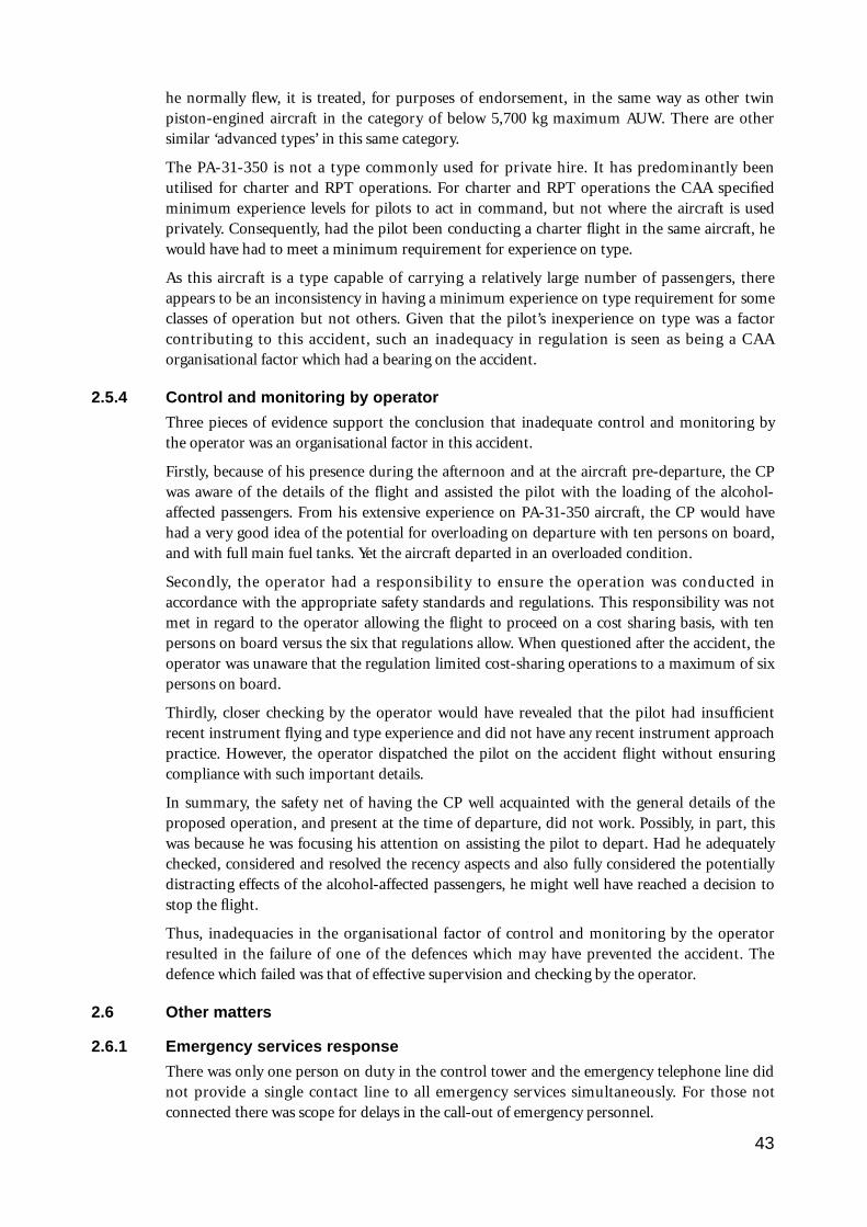
he normally flew, it is treated, for purposes of endorsement, in the same way as other twinpiston-engined aircraft in the category of below 5,700 kg maximum AUW. There are othersimilar ‘advanced types’ in this same category.
The PA-31-350 is not a type commonly used for private hire. It has predominantly beenutilised for charter and RPT operations. For charter and RPT operations the CAA specifiedminimum experience levels for pilots to act in command, but not where the aircraft is usedprivately. Consequently, had the pilot been conducting a charter flight in the same aircraft, hewould have had to meet a minimum requirement for experience on type.
As this aircraft is a type capable of carrying a relatively large number of passengers, thereappears to be an inconsistency in having a minimum experience on type requirement for someclasses of operation but not others. Given that the pilot’s inexperience on type was a factorcontributing to this accident, such an inadequacy in regulation is seen as being a CAAorganisational factor which had a bearing on the accident.
2.5.4 Control and monitoring by operator
Three pieces of evidence support the conclusion that inadequate control and monitoring bythe operator was an organisational factor in this accident.
Firstly, because of his presence during the afternoon and at the aircraft pre-departure, the CPwas aware of the details of the flight and assisted the pilot with the loading of the alcohol-affected passengers. From his extensive experience on PA-31-350 aircraft, the CP would havehad a very good idea of the potential for overloading on departure with ten persons on board,and with full main fuel tanks. Yet the aircraft departed in an overloaded condition.
Secondly, the operator had a responsibility to ensure the operation was conducted inaccordance with the appropriate safety standards and regulations. This responsibility was notmet in regard to the operator allowing the flight to proceed on a cost sharing basis, with tenpersons on board versus the six that regulations allow. When questioned after the accident, theoperator was unaware that the regulation limited cost-sharing operations to a maximum of sixpersons on board.
Thirdly, closer checking by the operator would have revealed that the pilot had insufficientrecent instrument flying and type experience and did not have any recent instrument approachpractice. However, the operator dispatched the pilot on the accident flight without ensuringcompliance with such important details.
In summary, the safety net of having the CP well acquainted with the general details of theproposed operation, and present at the time of departure, did not work. Possibly, in part, thiswas because he was focusing his attention on assisting the pilot to depart. Had he adequatelychecked, considered and resolved the recency aspects and also fully considered the potentiallydistracting effects of the alcohol-affected passengers, he might well have reached a decision tostop the flight.
Thus, inadequacies in the organisational factor of control and monitoring by the operatorresulted in the failure of one of the defences which may have prevented the accident. Thedefence which failed was that of effective supervision and checking by the operator.
2.6 Other matters
2.6.1 Emergency services response
There was only one person on duty in the control tower and the emergency telephone line didnot provide a single contact line to all emergency services simultaneously. For those notconnected there was scope for delays in the call-out of emergency personnel.
43
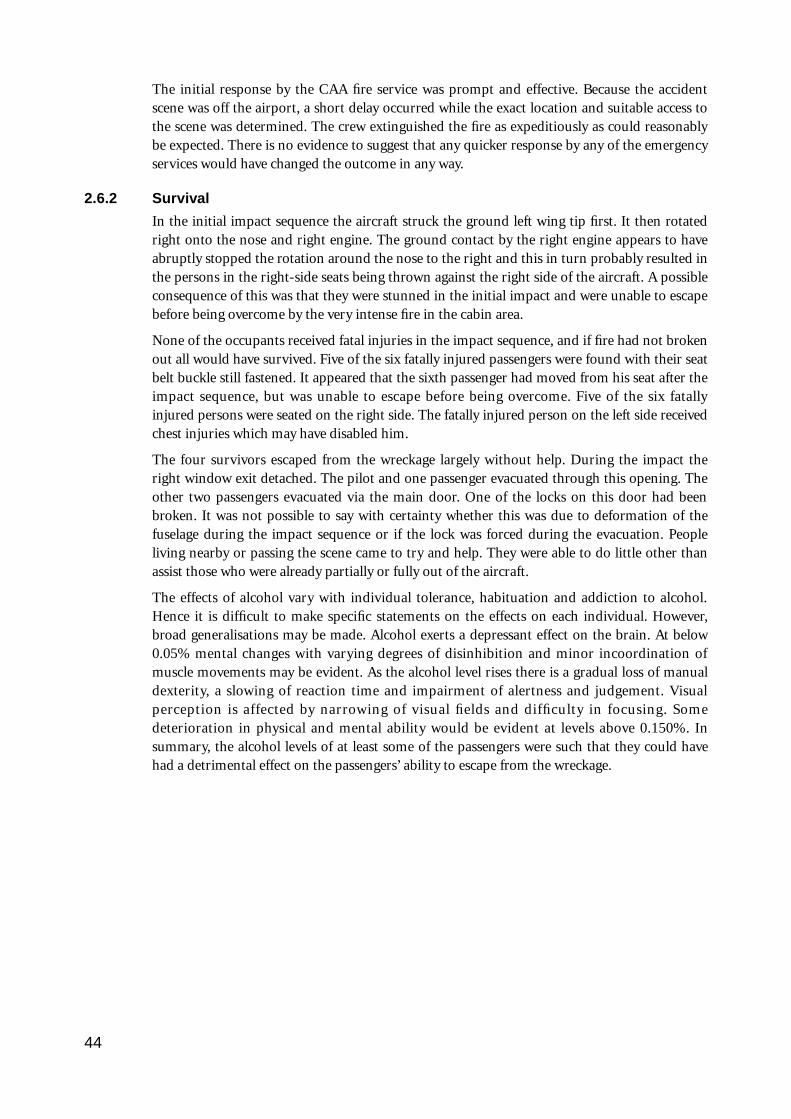
The initial response by the CAA fire service was prompt and effective. Because the accidentscene was off the airport, a short delay occurred while the exact location and suitable access tothe scene was determined. The crew extinguished the fire as expeditiously as could reasonablybe expected. There is no evidence to suggest that any quicker response by any of the emergencyservices would have changed the outcome in any way.
2.6.2 Survival
In the initial impact sequence the aircraft struck the ground left wing tip first. It then rotatedright onto the nose and right engine. The ground contact by the right engine appears to haveabruptly stopped the rotation around the nose to the right and this in turn probably resulted inthe persons in the right-side seats being thrown against the right side of the aircraft. A possibleconsequence of this was that they were stunned in the initial impact and were unable to escapebefore being overcome by the very intense fire in the cabin area.
None of the occupants received fatal injuries in the impact sequence, and if fire had not brokenout all would have survived. Five of the six fatally injured passengers were found with their seatbelt buckle still fastened. It appeared that the sixth passenger had moved from his seat after theimpact sequence, but was unable to escape before being overcome. Five of the six fatallyinjured persons were seated on the right side. The fatally injured person on the left side receivedchest injuries which may have disabled him.
The four survivors escaped from the wreckage largely without help. During the impact theright window exit detached. The pilot and one passenger evacuated through this opening. Theother two passengers evacuated via the main door. One of the locks on this door had beenbroken. It was not possible to say with certainty whether this was due to deformation of thefuselage during the impact sequence or if the lock was forced during the evacuation. Peopleliving nearby or passing the scene came to try and help. They were able to do little other thanassist those who were already partially or fully out of the aircraft.
The effects of alcohol vary with individual tolerance, habituation and addiction to alcohol.Hence it is difficult to make specific statements on the effects on each individual. However,broad generalisations may be made. Alcohol exerts a depressant effect on the brain. At below0.05% mental changes with varying degrees of disinhibition and minor incoordination ofmuscle movements may be evident. As the alcohol level rises there is a gradual loss of manualdexterity, a slowing of reaction time and impairment of alertness and judgement. Visualperception is affected by narrowing of visual fields and difficulty in focusing. Somedeterioration in physical and mental ability would be evident at levels above 0.150%. Insummary, the alcohol levels of at least some of the passengers were such that they could havehad a detrimental effect on the passengers’ ability to escape from the wreckage.
44
3. CONCLUSIONS
3.1 Findings
1. The aircraft was hired from the flying school at which the pilot was employed as aninstructor.
2. The pilot held a commercial pilot licence with a multi-engine command instrumentrating, and had received a Piper PA-31 type endorsement on 16 September 1993.
3. The pilot’s PA-31-350 endorsement training was carried out by the CP of the flyingschool.
4. To meet the recent experience requirement for carrying out an ILS approach, the pilot wasrequired to have made an actual or simulated ILS approach within the preceding 35 days.There was no record in the pilot’s logbook of any ILS approach within the 35 days beforethe accident. His logbook did not contain evidence of any instrument approaches in thepreceding 90 days. The pilot also did not have the required recent experience to conductan IFR flight.
5. There was no evidence of any medical or other problem affecting the pilot’s performance.He was required to wear glasses and did so.
6. There was no evidence that any aircraft mechanical malfunction existed that might havecontributed to the accident.
7. At takeoff the aircraft weight exceeded the maximum permissible take-off weight specifiedin the aircraft flight manual.
8. At the time of the accident the aircraft weight had been reduced by fuel burn-off to lessthan the maximum landing weight. The position of the centre of gravity was within limits.
9. The aircraft carried sufficient fuel for the flight.
10. The TAF obtained for the flight was inaccurate.
11. The pilot was inexperienced on the PA-31-350 type. Prior to commencing the flight he didnot have any instrument flight, IFR approach, or low-level circling approach experienceon that type of aircraft.
12. The flight did not meet the requirements for operation as a private flight.
13. The pilot did not have the required experience level on type to conduct a charter flight.
14. Despite flying through cloud below the MDA during the visual circling approach, amissed approach was not carried out in accordance with the provisions of AIP/DAP-IAL.
15. The pilot descended below the OCA during the circling approach.
16. Late on the circling approach a rapid descent developed which culminated in the aircraftcolliding with powerlines and the ground.
17. The CAA Common Crash Call facility was not connected to all relevant emergencyservices.
18. The CAA Airport Fire Service responded in a prompt and efficient manner to theemergency. The necessary time taken for the fire vehicles and other services to reach thescene did not affect the survivability of the occupants.
45
19. Organisational factors identified in relation to the CAA included:
• the absence of adequate specific requirements for type endorsement training, and forsuch training to also include instrument and night-flying requirements;
• the lack of an adequate requirement for comprehensive and assessable decision-making/judgement training in pilot training programs;
• inadequate AIP/DAP-IAL instructions concerning circling approaches (reflected invarying industry interpretations of the instructions, including differences in post-accident advice from the CAA on what the interpretations should be); and
• the absence of requirements for a minimum pilot experience level on the PA-31-350type before acting in command on a private IFR flight.
20. An organisational factor identified in relation to the operator was the inadequate controland monitoring of the planning and proposed conduct of the flight by the CP.
21. The ATC on duty acted in a sound and competent manner, both during the events leadingup to and subsequent to the accident.
3.2 Significant factors
1. The actual weather at Launceston at the time of arrival of VH-WGI was significantly worsethan forecast.
2. The pilot did not have the required recent experience to conduct either an IFR flight or anILS approach. The operator’s procedures did not detect this deficiency.
3. The pilot’s inexperience and limited endorsement training did not adequately prepare himfor IFR flight in the conditions encountered.
4. The CAA did not specify adequate endorsement training or minimum endorsement timerequirements for aircraft of the class of the PA-31-350, particularly in regard to theendorsement of inexperienced pilots.
5. An absence of significant decision-making training requirements contributed to the poordecision-making action by the pilot who decided to continue with a visual circling approachat Launceston in conditions that were unsuitable for such an approach.
6. As a consequence of continuing the approach, the pilot subjected himself to an over-whelming workload. This was due to a combination of adverse weather conditions, his lackof training and experience in IFR approach procedures on the type, and a misinterpretationof (or non-compliance with) the AIP/DAP-IAL instructions, a combination which appearsto have influenced the pilot to fly a close-in, descending circuit at low altitude. The carriageof alcohol-affected passengers may have also added to the level of difficulty.
7. Because of workload, and possibly also due to distractions, the pilot inadvertently allowedthe aircraft to enter a rapid descent at a critical stage of the approach, at an altitude fromwhich recovery could not be effected.
46
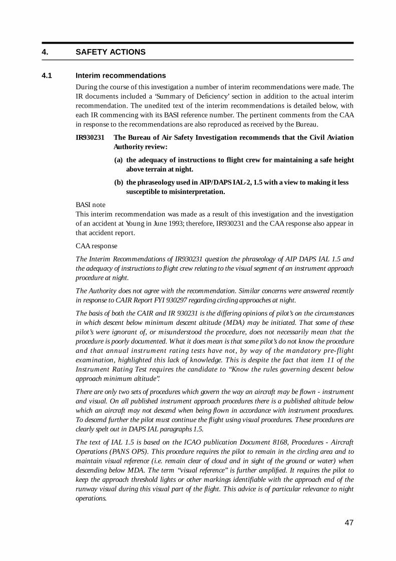
4. SAFETY ACTIONS
4.1 Interim recommendations
During the course of this investigation a number of interim recommendations were made. TheIR documents included a ‘Summary of Deficiency’ section in addition to the actual interimrecommendation. The unedited text of the interim recommendations is detailed below, witheach IR commencing with its BASI reference number. The pertinent comments from the CAAin response to the recommendations are also reproduced as received by the Bureau.
IR930231 The Bureau of Air Safety Investigation recommends that the Civil AviationAuthority review:
(a) the adequacy of instructions to flight crew for maintaining a safe heightabove terrain at night.
(b) the phraseology used in AIP/DAPS IAL-2, 1.5 with a view to making it less susceptible to misinterpretation.
BASI note This interim recommendation was made as a result of this investigation and the investigationof an accident at Young in June 1993; therefore, IR930231 and the CAA response also appear inthat accident report.
CAA response
The Interim Recommendations of IR930231 question the phraseology of AIP DAPS IAL 1.5 andthe adequacy of instructions to flight crew relating to the visual segment of an instrument approachprocedure at night.
The Authority does not agree with the recommendation. Similar concerns were answered recentlyin response to CAIR Report FYI 930297 regarding circling approaches at night.
The basis of both the CAIR and IR 930231 is the differing opinions of pilot’s on the circumstancesin which descent below minimum descent altitude (MDA) may be initiated. That some of thesepilot’s were ignorant of, or misunderstood the procedure, does not necessarily mean that theprocedure is poorly documented. What it does mean is that some pilot’s do not know the procedureand that annual instrument rating tests have not, by way of the mandatory pre-flightexamination, highlighted this lack of knowledge. This is despite the fact that item 11 of theInstrument Rating Test requires the candidate to “Know the rules governing descent belowapproach minimum altitude”.
There are only two sets of procedures which govern the way an aircraft may be flown - instrumentand visual. On all published instrument approach procedures there is a published altitude belowwhich an aircraft may not descend when being flown in accordance with instrument procedures.To descend further the pilot must continue the flight using visual procedures. These procedures areclearly spelt out in DAPS IAL paragraphs 1.5.
The text of IAL 1.5 is based on the ICAO publication Document 8168, Procedures - AircraftOperations (PANS OPS). This procedure requires the pilot to remain in the circling area and tomaintain visual reference (i.e. remain clear of cloud and in sight of the ground or water) whendescending below MDA. The term “visual reference” is further amplified. It requires the pilot tokeep the approach threshold lights or other markings identifiable with the approach end of therunway visual during this visual part of the flight. This advice is of particular relevance to nightoperations.
47
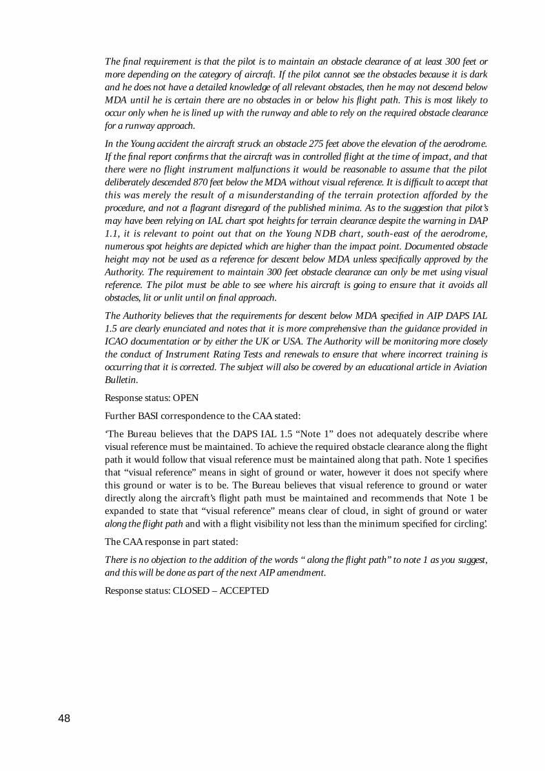
The final requirement is that the pilot is to maintain an obstacle clearance of at least 300 feet ormore depending on the category of aircraft. If the pilot cannot see the obstacles because it is darkand he does not have a detailed knowledge of all relevant obstacles, then he may not descend belowMDA until he is certain there are no obstacles in or below his flight path. This is most likely tooccur only when he is lined up with the runway and able to rely on the required obstacle clearancefor a runway approach.
In the Young accident the aircraft struck an obstacle 275 feet above the elevation of the aerodrome.If the final report confirms that the aircraft was in controlled flight at the time of impact, and thatthere were no flight instrument malfunctions it would be reasonable to assume that the pilotdeliberately descended 870 feet below the MDA without visual reference. It is difficult to accept thatthis was merely the result of a misunderstanding of the terrain protection afforded by theprocedure, and not a flagrant disregard of the published minima. As to the suggestion that pilot’smay have been relying on IAL chart spot heights for terrain clearance despite the warning in DAP1.1, it is relevant to point out that on the Young NDB chart, south-east of the aerodrome,numerous spot heights are depicted which are higher than the impact point. Documented obstacleheight may not be used as a reference for descent below MDA unless specifically approved by theAuthority. The requirement to maintain 300 feet obstacle clearance can only be met using visualreference. The pilot must be able to see where his aircraft is going to ensure that it avoids allobstacles, lit or unlit until on final approach.
The Authority believes that the requirements for descent below MDA specified in AIP DAPS IAL1.5 are clearly enunciated and notes that it is more comprehensive than the guidance provided inICAO documentation or by either the UK or USA. The Authority will be monitoring more closelythe conduct of Instrument Rating Tests and renewals to ensure that where incorrect training isoccurring that it is corrected. The subject will also be covered by an educational article in AviationBulletin.
Response status: OPEN
Further BASI correspondence to the CAA stated:
‘The Bureau believes that the DAPS IAL 1.5 “Note 1” does not adequately describe wherevisual reference must be maintained. To achieve the required obstacle clearance along the flightpath it would follow that visual reference must be maintained along that path. Note 1 specifiesthat “visual reference” means in sight of ground or water, however it does not specify wherethis ground or water is to be. The Bureau believes that visual reference to ground or waterdirectly along the aircraft’s flight path must be maintained and recommends that Note 1 beexpanded to state that “visual reference” means clear of cloud, in sight of ground or wateralong the flight path and with a flight visibility not less than the minimum specified for circling’.
The CAA response in part stated:
There is no objection to the addition of the words “ along the flight path” to note 1 as you suggest,and this will be done as part of the next AIP amendment.
Response status: CLOSED – ACCEPTED
48
IR930292 The Bureau of Air Safety Investigation recommends that the Civil AviationAuthority review its procedures with respect to information contained inATC/emergency service communications. This review should emphasise thatdiscretion should be used when broadcasting sensitive and disturbinginformation which could be heard by flight crew.
CAA response
This is to advise that we have reviewed our procedures with respect to information contained inATC/emergency service communications.
As a result of previous recommendations we have amended our documents stating that the“appropriate ground control frequency should normally be used for communication between a pilotand the RFFS vehicles”.
The incident that generated this recommendation occurred at a single-person facility. In this case,and indeed in all other situations, I feel that the concept of having a separate frequency for emergencyservices would exacerbate the situation. It is generally undesirable for controllers to handle more thanone frequency (without re-transmission) during busy periods or times of added stress.
In conclusion, in the light of the seemingly unusual circumstances associated with this incident, Ido not believe that procedures need to be changed, nor additional facilities be provided.
Response status: CLOSED – NOT ACCEPTED
IR930313 The Bureau of Air Safety Investigation recommends that the Civil AviationAuthority review;
a) the Common Crash Call System with a view to ensuring that the activationof the call accesses all agencies identified as necessary for an emergencyresponse.
b) the operational communication systems to ensure that continuousair/ground communications are available automatically in the event of amains power supply failure.
c) the AVR power supply system with a view to ensuring that continuous voicerecording is available in the event of a mains power supply failure.
CAA response
The BASI interim recommendations have been reviewed and the following action has been taken:
1. The Common Crash Call function has been removed and a dedicated phone line has beeninstalled between Launceston Tower and Tasmania Police Northern District. Effective fromMonday 31 January emergency procedures have changed, and in the event of a need forLaunceston city emergency services to be notified, the tower will contact the Police. The policeare responsible for notifying the Launceston Fire Brigade, hospital and ambulance service. Thenew system is similar to the emergency procedures in operation at Hobart Airport withTasmania Police and at Melbourne Airports with Victoria Police.
2. The failure to connect the Automatic Voice Recorder to standby power was an oversight whichresulted when the recorders were moved from the Launceston Terminal building a couple ofyears ago. The AVR power supply was modified immediately after the crash when it wasapparent the system had failed and is now connected to the tower equipment room SPS, whichis a battery backup system which through an inverter converts 72V DC to 240V AC, and resultsin a no break supply to the AVR.
49
3. The present procedure whereby the tertiary system can be brought on line by the towercontrollers is considered to provide an operationally acceptable means of maintainingcommunications. Tower controllers have been reminded of the need to select the airport basedtertiary system in the event of an emergency situation coinciding with a power failure whichmay cause microwave link failures.
Response status: CLOSED – ACCEPTED
IR940017 The Bureau of Air Safety Investigation recommends that the Civil AviationAuthority review the requirements for issue of type endorsement as specified inCAO 40.1.0. This review should be conducted to ensure that:
(1) a minimum syllabus is specified for an initial multi-engine rating and forendorsements on multi-engine aircraft below 5700 kg MTOW of a higherPerformance Category. The syllabus should include:
(a) General Handling, including stalling;
(b)Takeoff, circuit and landing;
(c) Instrument flying, including an instrument and circling approach;
(d)Asymmetric flight;
(e) Night flying.
(2) the Performance Category of each aircraft type is clearly defined in CAO40.1.0, appendix I.
CAA response
The Authority agrees with the recommendations and has proceeded to implement them.
A comprehensive multi-engine aeroplane training syllabus has been drafted and has receivedcomment from experts both from industry and from within the Authority. The syllabus has beendesigned to cater particularly for the pilot who is converting for the first time to a multi-enginecraft. It also calls up training at night and under the IFR if applicable, and addresses training ingas turbine powered craft and multi-crew operations. I expect that it will be in print as the officialCAA syllabus by year’s end, though its use will not be mandatory until the relevant amendments tolegislation have been approved.
Accordingly, a proposal has been raised to amend CAO 40.1.0 such that training and experience forinitial and follow-on multi-engine endorsements will have to be completed in accordance with anew set of requirements. These would include training to be completed in accordance with thesyllabus, dual flight time requirements to depend on the aeroplane performance category andpossible additional training in gas turbine powered, pressurised aircraft. Comment is currentlybeing sought from Authority technical specialists on this proposal, but gauging from initialreactions I feel there is strong support for the change.
Though I would hope that the review and subsequent amendment action will be complete byMarch 1995, I must caution that there are a considerable number of high priority tasks awaitinglegislative drafting. As a result, this task may slip depending on the progression of tasks ahead of iton the task list.
Nevertheless, the syllabus production will go ahead and its existence will be widely publicised. Trainingorganisations will be encouraged to use it to ensure standardised and hopefully high quality training.
Response status: CLOSED – ACCEPTED
50
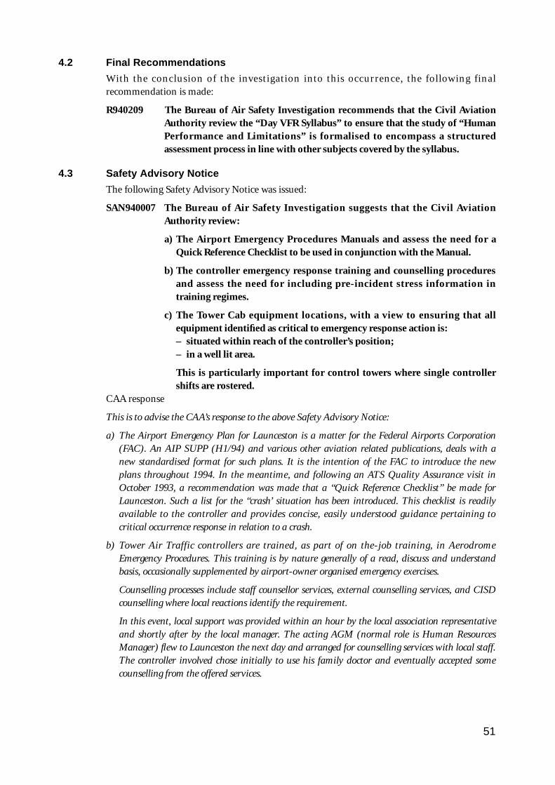
4.2 Final Recommendations
With the conclusion of the investigation into this occurrence, the following finalrecommendation is made:
R940209 The Bureau of Air Safety Investigation recommends that the Civil AviationAuthority review the “Day VFR Syllabus” to ensure that the study of “HumanPerformance and Limitations” is formalised to encompass a structuredassessment process in line with other subjects covered by the syllabus.
4.3 Safety Advisory Notice
The following Safety Advisory Notice was issued:
SAN940007 The Bureau of Air Safety Investigation suggests that the Civil AviationAuthority review:
a) The Airport Emergency Procedures Manuals and assess the need for aQuick Reference Checklist to be used in conjunction with the Manual.
b) The controller emergency response training and counselling proceduresand assess the need for including pre-incident stress information intraining regimes.
c) The Tower Cab equipment locations, with a view to ensuring that allequipment identified as critical to emergency response action is:– situated within reach of the controller’s position;– in a well lit area.
This is particularly important for control towers where single controllershifts are rostered.
CAA response
This is to advise the CAA’s response to the above Safety Advisory Notice:
a) The Airport Emergency Plan for Launceston is a matter for the Federal Airports Corporation(FAC). An AIP SUPP (H1/94) and various other aviation related publications, deals with anew standardised format for such plans. It is the intention of the FAC to introduce the newplans throughout 1994. In the meantime, and following an ATS Quality Assurance visit inOctober 1993, a recommendation was made that a “Quick Reference Checklist” be made forLaunceston. Such a list for the “crash’ situation has been introduced. This checklist is readilyavailable to the controller and provides concise, easily understood guidance pertaining tocritical occurrence response in relation to a crash.
b) Tower Air Traffic controllers are trained, as part of on the-job training, in AerodromeEmergency Procedures. This training is by nature generally of a read, discuss and understandbasis, occasionally supplemented by airport-owner organised emergency exercises.
Counselling processes include staff counsellor services, external counselling services, and CISDcounselling where local reactions identify the requirement.
In this event, local support was provided within an hour by the local association representativeand shortly after by the local manager. The acting AGM (normal role is Human ResourcesManager) flew to Launceston the next day and arranged for counselling services with local staff.The controller involved chose initially to use his family doctor and eventually accepted somecounselling from the offered services.
51
The suggested “pre accident stress information” as part of an ATC training course has beenreferred to the ATS AGM Human Resources for further investigation. He will be requesting anexpanded explanation of the suggestion from BASI.
c) Equipment identified as critical to emergency response action in the “Summary of Deficiency”can be taken as telephone and “telephone books” (presumably AEP documents).
Specifically in the Launceston Tower case, which is equipped to be a single person toweroperation:– the Erichaphon handset and keyboard pad in the console, which enables PABX and
external telephone access, is deliberately designed to facilitate single person operation, andenables use of air ground communication, intercom, and telephone services through a singlehand piece. Rather than distracting, it is expected that with one hand piece the controllercan regulate all calls. BASI comments are noted and an extension cord will be provided fora PABX extension which can be used at the console.
– the AEP Manual is kept in a specially designed holder under the front of the work surface.
– night lighting in the Tower is specifically designed to ensure controller night vision is notimpaired, to maximise the potential to observe events outside the Tower. Alternative lightsources are available for all work areas using standard switches.
In conclusion it needs to be said that the incident that lead to these “Deficiencies” was handled bythe controller on duty both professionally and capably. He handled a situation which was highlystressful with Aerodrome Emergency Procedures in operation, a power failure, a number of otherinbound aircraft, and more-than-forecast low cloud requiring ILS approaches by subsequentaircraft.
52