Embed Size (px)
Citation preview

Pipeline long-range inspection and monitoring by an innovative magnetic collar for magnetostrictive guided-wave systems
Francesco BERTONCINI, Marco RAUGI, Florin TURCU
Department of Electrical Systems and Automation , University of Pisa; Pisa, Italy Phone: +39 050 2217300, Fax: +39 050 2217333; e-mail: {bertoncini, raugi, turcu}@dsea.unipi.it
Abstract In this paper, a new system for pipeline long-range inspection and monitoring is described. The system is based on a set of local magnetostrictive sensors surrounding the inspected pipeline. The local signal acquisition allowed by each individual sensor and the subsequent detection process makes possible a better identification and classification of flaws and their geometrical characterization. In addition a software packet that includes algorithms for flaw recognition was developed. Finally, an experimental campaign to test and validate the new system and software is presented.
Keywords: long range inspection; monitoring; guided wave; ultrasonics; magnetostrictive transducer; angular profile. 1. Background Corrosion and defects in pipelines are general problems, particularly in the oil, gas, petro-chemical industries and for the water and gas distribution. Since a significant percentage of industrial pipelines are insulated, this means that even external corrosion cannot readily be detected without the removal of the insulation, which in most cases is prohibitively expensive. Moreover, in the case of inaccessible pipelines, visual or conventional non-destructive inspection can become very expensive, thus an important inconvenient. Furthermore, a technique capable to perform in-service inspection would be greatly useful for continuous cycle plants as the petro-chemical ones [1], [2]. In this paper the attention is focused on long-range guided waves (GW) used for the rapid survey of pipes and plates, for detection of both internal and external corrosion [3]. These waves are characterized by relatively low frequencies (typically under 200 kHz) and can propagate over long distance (tens of meters) in any bounded structural parts, including rods, pipes, and plates [4]. The main attraction of long-range guided wave inspection is that it allows a large area of structure to be tested from a single transducer position, thus avoiding the time consuming scanning required by conventional ultrasonic or eddy current methods. The technique becomes even more attractive if part of the structure to be tested is inaccessible, for example a road-, river- or railway-crossing . The test is usually done in pulse-echo mode, the transducer transmitting the guided wave along the structure. Returning echoes indicate the presence of defects or other structural features. This technology performs 100-percent volumetric examination of a large area of a pipe and detects and locates both internal and external defects in the sections around the test position. Fig. 1 sketches the basic elements of the guided wave technology applied to the piping system inspection.
NDT.net - The e-Journal of Nondestructive Testing (December 2008)For more papers of this publication click: www.ndt.net/search/docs.php3?MainSource=25

As long-range GW have the ability to interrogate from a single probe position a structure over long distances for defects such as cracks and corrosion wastage, the technique can be a very effective means of surveying and monitoring large structures for their structural conditions. Thus, non-destructive detection and classification of pipe integrity using long-range GW is of actual interest in many industrial applications where the pipe corrosion is one of the major problems for plant maintenance [5].
Fig. 1 - Basic elements for GW piping systems inspection 2. Inspection and monitoring with magnetostrictive systems A magnetostrictive transducer based on the magnetostrictive strip (MsS®) consists of two components [6]: - a thin strip of ferromagnetic material that has good magnetostrictive properties, such as nickel or iron-cobalt alloy, bonded to the structure under test; the strip is magnetized with a static bias magnetic field needed for transducing operation; - a coil that applies time-varying magnetic fields to the ferromagnetic material in order to generate guided waves in the material. The coil also plays a role of inductively detecting the magnetic flux change caused in the material by the incoming guided waves. A commercially available long-range guided wave inspection instrument based on magnetostrictive transducers (MsS®) has been developed by the South West Research Institute, in San Antonio, TX, USA [7]. In the following, some examples of inspection and structural health monitoring performed with this instrument are shown [8]. 2.1 Inspection 2.2.1 Suspended and partially buried gas pipeline The inspection parameters and the pipeline’s geometry are shown in Tab. 1 and in Fig. 3 respectively.
Fig. 2 – MsS sensor.
Usage Rapid screening of remote large areas
Waves used Guided waves Frequency range
< 200 kHz
Defect detection Relatively large defects
Inspection range Up to on hundred meters in ideal condition

Tab. 1 - Inspection parameters Pipeline Composed of welded pipes, each one: 10 or 12 m long; Diameter:
6 inch; Thickness 3,2 mm Coating: no; Fluid: gas; In-line inspection: yes
Discontinuities Welds; elbows; artificial non symmetric defects made by bonding to the pipe of a certain number of metallic sheets with known geometry
Guided wave mode: torsional; frequency: 32 kHz; operating mode: pulse/echo Inspection range 120 m; 108 m along the pipeline suspended in air and 12m buried
Tx/Rx
Non symmetric defect
+ 60 m
Weld
−−−− 60 m
Tx/Rx Elbow Buried pipeline
Positive direction Negative direction
Joint (not directly visible)
Fig. 3 - Pipeline geometry All geometrical discontinuities represented in Fig. 3 can be identified in the signal acquired with the system MsS2020D as shown in Fig. 4. The inspection results show a low level of corrosion indicated by the low attenuation rate.
Fig. 4 - In-line pipeline inspection: negative and positive direction. 2.2.1 Suspended coated gas pipeline This test is related to an in-service gas pipeline situated in correspondence of a river crossing, thus inaccessible for classical inspection methods. The pipeline is coated in polyethylene for its entire length and presented elbows and welds at the two interfaces with the ground. The inspection parameters and the pipeline’s geometry and image are shown in Tab. 2, Fig. 5 and Fig. 6(a) respectively. In the acquired RF signal, shown in Fig. 6(b), it is possible detected not only the double elbows GD1, GD2 and the point INT where the pipeline is buried but also three reflected signals (see circle in Fig. 6(b)). Two of the reflected signals can be associated with two joints invisible by visual inspection.

Tab. 2 - Inspection parameters Pipeline Diameter: 6 inch; Coating: yes; Fluid: gas; In-line inspection: yes Discontinuities joints, elbows Guided wave mode: torsional; frequency: 16 kHz; operating mode: pulse/echo Inspection range 60 m; Tx/Rx
PE coating
+ 60 m
Weld Tx/Rx Elbow Buried pipeline
bridge
GD1 GD2 INT GD0
Fig. 5 - Pipeline geometry
Fig. 6 - Coated pipeline inspection: (a) pipeline; (b) acquired RF signal. 2.2 Monitoring The MsS2020D diagnostic system is based on magnetostrictive strips; the strips must be bonded to the pipeline and then magnetized. The stability over time of the system based on this sensor has been tested on the pipeline considered in section 2.2.1. In July 2005 a first test was performed: two Ni strips were bonded and pre-magnetized. After the acquisition, the strips were left on the pipeline. A year and a half later- January 2007, the test was repeated without the re-magnetization of the strips: the signals obtained were comparable in shape and amplitude with the signal related to the first test: the pipeline state hasn’t changed over time. Further tests proved that:
- it is possible to perform structural health monitoring –SHM- on coated pipelines following the procedure illustrated in Fig. 7 where the following phases are defined: (a) acquisition without the coating: the coils are placed on the magnetostrictive strips bounded in the pipe; (b) apply coating on the pipe and magnetostrictive strips; (c) acquisition with the coating between the strips and the coils.
- the MsS system, used as monitoring system, is able to detect corrosion regions from early stages.

Fig. 7 - Monitoring of PE coated pipelines: phases of the executed test. 3. The new magnetic guided-wave sensor In [9] a new GW acquisition system has been presented. It is capable of step by step data acquisition around the pipe circumference (Fig. 8) providing useful information to geometrically characterize detected discontinuities.
An example of test results is given in Fig. 9. The test corresponds to a 30 m pipe section (Fig.9-a) with welds and several artificial flaws. The results (Fig. 9-b) were obtained with a circumferential resolution of 45 steps. The main problems met when using the local acquisition
system was the difficulty to accomplish a uniform step and trajectory when moving it around the pipe circumference. These issues brought to additional errors in the process of estimation of the flaw geometry.
Fig. 9(b) - Validation of local acquisition system: (a) inspected pipeline; (b) results
In this paper, a new GW acquisition sensor is described that overcomes issues like non uniform movement of the local sensor around the circumference (non uniform step size and trajectory).
(a) (b) (c)
Fig. 8 - Local acquisition system – previous version
Fig.9 (a)

3.1 The GW acquisition collar and signal processing software The new system is made of a collar of sensors as shown in Fig. 10 each one being similar to the one described in [9], [10]. It allows the GW acquisition in multiple circumferential positions of the same axial plane of the pipe. The symmetrical torsional guided wave is generated by a magnetostrictive strip sensor (Fig. 2). Symmetrical discontinuities (welds, joints) create symmetrical reflected waves, while asymmetrical discontinuities (usually flaws) generate more complex wave fronts. The two cases can be discriminated by using multiple sensor elements uniformly distributed around the pipe circumference. Moreover, the amount of data acquired in the various circumferential positions is used as input for feature recognition algorithms. Dedicated software has been developed [11] to assist the NDT operator in the process of acquisition and interpretation of results. The software packet comprises a number of visualisation modes as well as a tool to estimate the circumferential extet of a detected discontinuity/flaw. Visualisation modes With the new software, the operator has the possibility to choose among different types of visualization of results. On the other hand, the multiple sensor acquisition allows the representation of all the circumferential signals together on the same graph. This can be done in the RF or video mode. In addition a pipeline condition mapping is available for a better interpretation of the results.
Fig. 11 - Visualization modes with the new GW system (RF, Video and mapping)
Fig. 10 - Magnetostrictive collar
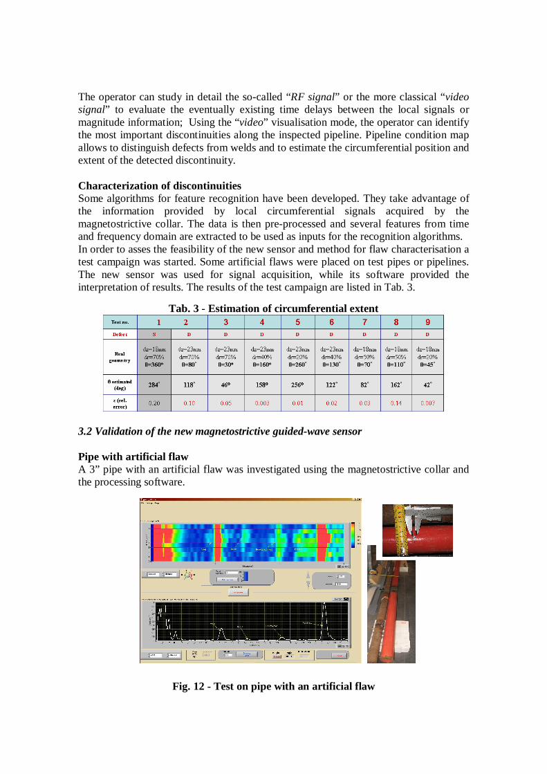
The operator can study in detail the so-called “RF signal” or the more classical “video signal” to evaluate the eventually existing time delays between the local signals or magnitude information; Using the “video” visualisation mode, the operator can identify the most important discontinuities along the inspected pipeline. Pipeline condition map allows to distinguish defects from welds and to estimate the circumferential position and extent of the detected discontinuity. Characterization of discontinuities Some algorithms for feature recognition have been developed. They take advantage of the information provided by local circumferential signals acquired by the magnetostrictive collar. The data is then pre-processed and several features from time and frequency domain are extracted to be used as inputs for the recognition algorithms. In order to asses the feasibility of the new sensor and method for flaw characterisation a test campaign was started. Some artificial flaws were placed on test pipes or pipelines. The new sensor was used for signal acquisition, while its software provided the interpretation of results. The results of the test campaign are listed in Tab. 3.
Tab. 3 - Estimation of circumferential extent
3.2 Validation of the new magnetostrictive guided-wave sensor Pipe with artificial flaw A 3” pipe with an artificial flaw was investigated using the magnetostrictive collar and the processing software.
Fig. 12 - Test on pipe with an artificial flaw

The flaw (3 holes in circumferential direction, less than 50% deep in the pipe-wall) was clearly distinguished from the weld and pipe-end reflections. Furthermore its circumferential extent was estimated between 80 and 100 degrees which is a 9 to 15% relative error, considering the real circumferential extent as being 45 degrees. Test on PE coated pipes Another important application of the magnetostrictive collar is inspection and monitoring of PE coated pipelines. Two examples are given. The firs one considers a PE coated, 10”, 12 m long pipe with an artificial 45 degree defect. The second describes the test done on a welded PE coated, 24 m long pipe. The results for both cases show a clear identification of symmetrical discontinuities (welds and pipe ends) and the asymmetrical one (artificial flaw). In addition a good estimation of the circumferential extent of the flaw was made, with only 7% relative error.
Fig. 13 - Test on coated pipe with artificial defect
Fig. 14 - Test on coated welded pipes

4. Conclusions In this paper a new Guided Wave magnetic sensor was presented. It is based on the magnetostrictive strip technology and is provided with an innovative acquisition system and data processing software. Both hardware – magnetostrictive collar- and processing/analysis software were described. Moreover, the results of a test campaign have underlined the main characteristics of the new GW system. Part of them are listed in Tab. 4
Tab. 4 – Characteristics of the magnetostrictive collar GW system confirmed experimentally
Sensitivity 2% of “cross-sectional area” change Frequency 12 to 64 kHz Wave mode Torsional Pipe size 3”, 4”, 6”, 8”, 10” Inspection range 10 ÷ 90 m for every direction; the effective range depends
on pipeline geometry (diameter, number of joints, elbows, branches) and pipeline state (pipeline suspended or buried, pipeline coated or uncoated)
Time required for inspection
A few minutes once the magnetostrictive strips are bonded
Circumferential resolution (acquisition step size)
At present, the collar elements have the circumferential extent of 7 cm resulting in a 7cm step size*
Inspection of coated pipelines
Successfully tested with Polyethylene coatings
Permanent installation of the sensor
Possible for monitoring (also for coated pipelines)
* Research is under way to decrease the step size for a more complete data acquisition thus more accurate characterisation of discontinuities. References 1. J. Heerings, N. Trimborn, A. den Herder: “Inspection Effectiveness and its
Effects on the Integrity of Pipework”, Proceedings ECNDT 2006, 9th European Conference on NDT, Berlin, Germany, September 25-29, 2006.
2. J. B. Nestleroth, “Pipeline In-line Inspection – Challenges to NDT”, ECNDT 2006, 9th European Conference on NDT, Berlin, Germany, September 25-29, 2006.
3. D.N. Alleyene, B. Pavlakovic, “Rapid Long Range Inspection of Chemical Plant Pipework using Guided Waves”, Proceedings 15th WCNDT, Roma, 2000.
4. J. D. Achenbach, Wave propagation in elastic solids, North-Holland/ American Elsevier, The Netherlands, 1975.
5. P. Mudge, P. Catton, “Monitoring of Engineering Assets using Ultrasonic Guided Waves”, Proceedings ECNDT 2006, 9th European Conference on NDT, Berlin, Germany, September 25-29, 2006.

6. M.-S. Choi, S.-Y. Kim and H. Kwun, “An Equivalent Circuit Model of Magnetostrictive Transducers for Guided Wave Applications”, Journal of the Korean Physical Society, Vol. 47, No. 3, September 2005, pp. 454-462.
7. H. Kwun, S.-Y. Kim, and G. M. Light, “Magnetostrictive Sensor Guided-Wave Probes for Structural Health Monitoring of Pipelines and Pressure Vessels”, Sensor Systems and NDT Technology Department, Applied Physics Division, Southwest Research Institute, San Antonio, Texas, USA.
8. F. Bertoncini, M. Raugi, F. Turcu, “Magnetostrictive sensors for long range guided wave inspection and monitoring of in-service pipelines”, IGRC 2008, International Gas Reunion Conference, Paris, France, October 08-10, 2008.
9. G. Acciani, F. Bertoncini, G. Brunetti, G. Fornarelli, M. Raugi, F. Turcu “Long Range Guided Wave Inspection of Pipelines by a New Local Magnetostrictive Transducer”, Proceedings 2007 IEEE International Ultrasonics Symposium, New York, USA, 2007.
10. F. Bertoncini, M. Raugi, F. Turcu, “Ispezione e monitoraggio di condutture a pressione basati sulla tecnica ad onde guidate”, SAFAP 2008, Convegno Sicurezza e affidabilità delle apparecchiature a pressione, Cagliari, Italia, 12-13 giugno 2008.
11. G. Acciani, F. Bertoncini, G. Brunetti, G. Fornarelli, M. Raugi, F. Turcu “Classification of defects for Guided Waves Inspected Pipes by a Neural Network Approach”, Proceedings 2007 IEEE International Ultrasonics Symposium, New York, USA, 2007.


![Ultrasonic Guided WavePhased Array Inspection ofPipelineseprints.nmlindia.org/3350/1/paper_JNDE[1].pdfpipe [6]. Current long-range guided wave techniques for pipeline inspection include](https://img.pdfslide.us/doc/110x75/60b3883dd8f4d07a6a78ac78/ultrasonic-guided-wavephased-array-inspection-1pdf-pipe-6-current-long-range.jpg)