Embed Size (px)
Citation preview

Pipe, Tube and Hose ClampsStauff is dedicated to solve your clamping problems from its broad range of catalog products or by a custom clamp designed byour experienced engineering department in conjunction with you, our customer.
STANDARD SERIESaccording to DIN 3015, Part 1 (for O.D. 6 to 102 mm)
HEAVY SERIESaccording to DIN 3015, Part 2(for O.D. 6 to 406 mm)
TWIN SERIESaccording to DIN 3015, Part 3 (for O.D. 6 to 42 mm)
SPECIAL CLAMPS / ACCESSORIES
MACHINED CUSTOM CLAMPS
MOLDED CUSTOM CLAMPS
LIGHT SERIES – Ideally suited for Pneumatics,Instrumentation, Machine Tool and Lubricationlines sizes from 1/8”-1”
CONSTRUCTION SERIES
TUBE AND PIPE CUSHION CLAMPS
U-BOLT CLAMPS
METAL CLAMPS ACCORDING TO DIN
TECHNICAL APPENDIX

Ci
Clamps - Profile and Approvals
STAUFF Clamps have been approved by:
• Bureau Veritas• Department of the Navy, New York• Germanischer Lloyd• Lloyd’s Register of Shipping• Registro Italiano Navale• TÜV• United States Coast Guard
In all industrial countries STAUFF Clamps are used to give aclean and distinct layout for all pipe, tube and hoseinstallations.
The vibration and noise reducing features are appreciated asbeing an important contribution to environmental protection.
Apart from the technical sophistication of STAUFF Clamps,the prompt delivery and service for both standard productand special constructions can be expected in all countries inthe world.
STAUFF Clamps applications are almost unlimited. Due tothe wide product range, all application areas where pipe,tube and hose are installed are covered:
• Industrial Hydraulics• Mobile Hydraulics• Marine Hydraulics• Offshore• General Industrial Pipe Construction• Mining Industry• Nuclear Reactor Construction• Instrumentation and Control Technology• Pneumatics
CLA
MP
S

C1
Clamps Index
PIPE TUBE AND HOSE CLAMPS• Profile and Approvals . . . . . . . . . . . . . . . . . . . . . . . . . . . . . . . . . . . . . . . . . . . . . . . .Ci• Index . . . . . . . . . . . . . . . . . . . . . . . . . . . . . . . . . . . . . . . . . . . . . . . . . . . . . . . . . . . .C1
STANDARD SERIES according to DIN 3015, Part 1 (for Pipe O.D. 6 to 102 mm)• Order Codes - Components . . . . . . . . . . . . . . . . . . . . . . . . . . . . . . . . . . . . . . . .C2-4• Dimensions - Components . . . . . . . . . . . . . . . . . . . . . . . . . . . . . . . . . . . . . . . .C5-7• Order Codes – Complete Clamps . . . . . . . . . . . . . . . . . . . . . . . . . . . . . . . . . . .C8-10
HEAVY SERIES according to DIN 3015, Part 2 (for Pipe O.D. 6 to 406 mm)• Order Codes - Components . . . . . . . . . . . . . . . . . . . . . . . . . . . . . . . . . . . . .C11-13• Dimensions - Components . . . . . . . . . . . . . . . . . . . . . . . . . . . . . . . . . . . . . .C14-16• Order Codes – Complete Clamps . . . . . . . . . . . . . . . . . . . . . . . . . . . . . . . . . .C17-19
TWIN SERIES according to DIN 3015, Part 3 (for Pipe O.D. 6 to 42 mm)• Order Codes - Components . . . . . . . . . . . . . . . . . . . . . . . . . . . . . . . . . . . . . .C20-21• Dimensions - Components . . . . . . . . . . . . . . . . . . . . . . . . . . . . . . . . . . . . . . .C22-23• Order Codes – Complete Clamps . . . . . . . . . . . . . . . . . . . . . . . . . . . . . . . . . .C24-25
SPECIAL CLAMPS / ACCESSORIES• RI-Clamps (Pipe Clamps with Rubber Insert) . . . . . . . . . . . . . . . . . . . . . . . . . . .C26• Heavy Series - Twin Design . . . . . . . . . . . . . . . . . . . . . . . . . . . . . . . . . . . . . . . . .C27• Angled, Bridge and Elongated Weld Plates, Safety Washers, Special Clamps . .C28• Clamps for Proximity Switches and Electric Cables . . . . . . . . . . . . . . . . . . . . . .C29• Saddle Clamp for Cylinder Supply Lines - ZR Series . . . . . . . . . . . . . . . . . . . . .C29• Junction Adaptor Clamps . . . . . . . . . . . . . . . . . . . . . . . . . . . . . . . . . . . . . . . . . . .C30• Truck Brake Line Clamps . . . . . . . . . . . . . . . . . . . . . . . . . . . . . . . . . . . . . . . . . . .C30• Compact Twin Series . . . . . . . . . . . . . . . . . . . . . . . . . . . . . . . . . . . . . . . . . . . . . .C31• Agricultural Clamps . . . . . . . . . . . . . . . . . . . . . . . . . . . . . . . . . . . . . . . . . . . . . . .C31
CUSTOM DESIGNED CLAMPS• Machined Version . . . . . . . . . . . . . . . . . . . . . . . . . . . . . . . . . . . . . . . . . . . . . . . . .C32• Injection Molded Version – Flexi-Clamp . . . . . . . . . . . . . . . . . . . . . . . . . . . . . . . .C33
LIGHT SERIES• LB . . . . . . . . . . . . . . . . . . . . . . . . . . . . . . . . . . . . . . . . . . . . . . . . . . . . . . . . . . . . .C34• LBG | LBU . . . . . . . . . . . . . . . . . . . . . . . . . . . . . . . . . . . . . . . . . . . . . . . . . . . . . .C35• LN . . . . . . . . . . . . . . . . . . . . . . . . . . . . . . . . . . . . . . . . . . . . . . . . . . . . . . . . . . . . .C36• LNGF | LNUF . . . . . . . . . . . . . . . . . . . . . . . . . . . . . . . . . . . . . . . . . . . . . . . . . . . .C37
CONSTRUCTION SERIES• KS | KSV | DKS | DKSV . . . . . . . . . . . . . . . . . . . . . . . . . . . . . . . . . . . . . . . . . . . .C38
CUSHION CLAMPS - Tube and Pipe• STC/SPC Series . . . . . . . . . . . . . . . . . . . . . . . . . . . . . . . . . . . . . . . . . . . . . . .C39-42
U-BOLT CLAMPS• FLAT STEEL U-BOLT CLAMPS – FB | RUK . . . . . . . . . . . . . . . . . . . . . . . . . . . .C43• ROUND STEEL U-BOLT CLAMPS – RB | RUK . . . . . . . . . . . . . . . . . . . . . . . . . .C44• RB | RUL . . . . . . . . . . . . . . . . . . . . . . . . . . . . . . . . . . . . . . . . . . . . . . . . . . . . . . .C45• RBD according to DIN 3570, Type A . . . . . . . . . . . . . . . . . . . . . . . . . . . . . . . . . .C46
METAL PIPE CLAMPS ACCORDING TO DIN• DIN 3567, Type A . . . . . . . . . . . . . . . . . . . . . . . . . . . . . . . . . . . . . . . . . . . . . . . . .C47• DIN 3567, Type B . . . . . . . . . . . . . . . . . . . . . . . . . . . . . . . . . . . . . . . . . . . . . . . . .C47• DIN 1592 . . . . . . . . . . . . . . . . . . . . . . . . . . . . . . . . . . . . . . . . . . . . . . . . . . . . . . .C48• DIN 1593 . . . . . . . . . . . . . . . . . . . . . . . . . . . . . . . . . . . . . . . . . . . . . . . . . . . . . . .C48• DIN 1596 . . . . . . . . . . . . . . . . . . . . . . . . . . . . . . . . . . . . . . . . . . . . . . . . . . . . . . .C49• DIN 1597 . . . . . . . . . . . . . . . . . . . . . . . . . . . . . . . . . . . . . . . . . . . . . . . . . . . . . . .C49
TECHNICAL APPENDIX• Design of Clamp Bodies . . . . . . . . . . . . . . . . . . . . . . . . . . . . . . . . . . . . . . . . . . . .C50• Installation Information . . . . . . . . . . . . . . . . . . . . . . . . . . . . . . . . . . . . . . . . . . . . .C51• Materials, Material Properties and Technical Information . . . . . . . . . . . . . . . . . .C52• Recommended Distance between Clamps . . . . . . . . . . . . . . . . . . . . . . . . . . . . .C53• Basic Mounting Instructions . . . . . . . . . . . . . . . . . . . . . . . . . . . . . . . . . . . . . . . . .C53• Thread Chart: Metric vs. UNC Thread . . . . . . . . . . . . . . . . . . . . . . . . . . . . . . . . .C53• Tightening Torques and Maximum Loads in Pipe Direction . . . . . . . . . . . . . . . .C54
• Notes . . . . . . . . . . . . . . . . . . . . . . . . . . . . . . . . . . . . . . . . . . . . . . . . . . . . . . . . . .C55
CLA
MP
S

Clamps - Standard Series (for O.D. 6 to 102 mm)
ORDER CODES - COMPONENTS according to DIN 3015, Part 1
Clamps - Standard Series (for O.D. 6 to 102 mm)
ORDER CODES - COMPONENTS according to DIN 3015, Part 1
C2
CLA
MP
S
C3
Group 1
Group 1A -6
Group 1
Group 1A -6
Group 1
Group 1A -8
StackingBoltAF
TwinWeld Plate
DSP
GroupWeld Plate
RAP
CoverPlateDP
HexagonHead Bolt
AS
Insert
E
HexagonHead Bolt
ASE
SocketCap Screw
IS
Slotted HeadScrew
LI
for use withCOVER PLATE
DP
no coverplate
for use withINSERT
E
W2 W1 W3 W3 STEEL /PLASTIC
W3 W3 W3 W3
DSP 1/40 ✱ ✱✱
DSP 1A/37 ✱ ✱✱
DSP 3/52 ✱ ✱✱
DSP 4/60 ✱ ✱✱
DSP 5/75 ✱ ✱✱
DSP 6/90 ✱ ✱✱
RAP 1/30/10 ✱ ✱✱
RAP 1A/37/10 ✱ ✱✱
RAP 2/44/10 ✱ ✱✱
RAP 3/52/10 ✱ ✱✱
RAP 4/60/5 ✱ ✱✱
RAP 5/75/5 ✱ ✱✱
RAP 6/90/5 ✱ ✱✱
DP 1 ✱✱
DP 1A ✱✱
DP 2 ✱✱
DP 3 ✱✱
DP 4 ✱✱
DP 5 ✱✱
DP 7 ✱✱
DP 6 ✱✱
DP 8 ✱✱
AS1/1A ✱ ✱✱
AS1/1A ✱ ✱✱
AS 2 ✱ ✱✱
AS 3 ✱ ✱✱
AS 4 ✱ ✱✱
DSP ✱/✱✱ ✱ ✱✱
AS 5 ✱ ✱✱
AS 7 ✱ ✱✱
AS 6 ✱ ✱✱
AS 8 ✱ ✱✱
E ✱
S for SteelP for Plastic
ASE1/1A ✱ ✱✱
ASE1/1A ✱ ✱✱
ASE 2 ✱ ✱✱
ASE 3 ✱ ✱✱
ASE 4 ✱ ✱✱
ASE 5 ✱ ✱✱
- - -
ASE 6 ✱ ✱✱
- - -
IS1/1A ✱ ✱✱
IS1/1A ✱ ✱✱
IS 2 ✱ ✱✱
IS 3 ✱ ✱✱
IS 4 ✱ ✱✱
IS 5 ✱ ✱✱
IS 7 ✱ ✱✱
IS 6 ✱ ✱✱
IS 8 ✱ ✱✱
LI/1A ✱ ✱✱
LI/1A ✱ ✱✱
LI 2 ✱ ✱✱
LI 3 ✱ ✱✱
LI 4 ✱ ✱✱
LI 5 ✱ ✱✱
LI 6 ✱ ✱✱
AF1/1A ✱ ✱✱
AF1/1A ✱ ✱✱
AF 2 ✱ ✱✱
AF 3 ✱ ✱✱
AF 4 ✱ ✱✱
AF 5 ✱ ✱✱
AF 7 ✱ ✱✱
AF 6 ✱ ✱✱
AF 8 ✱ ✱✱
PIPE
CENT
ERSP
ACIN
G
STAU
FFGR
OUP
TWIN
WEL
DPL
ATE
DSP
TYPE
OFTH
READ
MAT
ERIA
L &
SURF
ACE
FINI
SHIN
G
RAP ✱/✱✱/✱ ✱ ✱✱
GROU
PW
ELD
PLAT
ERA
P
STAU
FFGR
OUP
PIPE
CENT
ERSP
ACIN
G
NUM
BER
OFCL
AMPS
MAT
ERIA
L &
SURF
ACE
FINI
SHIN
G
DP ✱ ✱✱
COVE
RPL
ATE
DP
STAU
FFGR
OUP
MAT
ERIA
L &
SURF
ACE
FINI
SHIN
G
AS ✱ ✱ ✱✱
HEXA
GON
HEAD
BOLT
AS
STAU
FFGR
OUP
MAT
ERIA
L &
SURF
ACE
FINI
SHIN
G
TYPE
OFTH
READ
TYPE
OFTH
READ
E ✱
INSE
RTE
MAT
ERIA
L(S
/P)
AF ✱ ✱ ✱✱ASE ✱ ✱ ✱✱ IS ✱ ✱ ✱✱ LI ✱ ✱ ✱✱
HEXA
GON
HEAD
BOLT
ASE
STAU
FFGR
OUP
MAT
ERIA
L &
SURF
ACE
FINI
SHIN
G
TYPE
OFTH
READ
SOCK
ETHE
ADSC
REW
ISST
AUFF
GROU
P
MAT
ERIA
L &
SURF
ACE
FINI
SHIN
G
TYPE
OFTH
READ
SLOT
TED
HEAD
SCRE
WLI
STAU
FFGR
OUP
MAT
ERIA
L &
SURF
ACE
FINI
SHIN
G
TYPE
OFTH
READ
STAC
KING
BOLT
AF
STAU
FFGR
OUP
MAT
ERIA
L &
SURF
ACE
FINI
SHIN
G
TYPE
OFTH
READ
- - -
- - -
- - -
- - -
- - -
- - -
- - -
- - -
DSP 2/44 ✱ ✱✱
SP 5 ✱✱✱ SPV 5 ✱✱✱5 5
3 3
1A 1
7 7
CLAMP BODYconsisting of two
clamp halves
SINGLEWELD PLATE
SP
ELONGATEDWELD PLATE
SPV
CHANNEL RAILADAPTOR
CRA
MATERIAL & SURFACE FINISHING CODE(ALL DISPLAYED OPTIONS ARE STANDARD DELIVERY)
SEE COMPONENTPART IDENTIFICATION
W2 W2 W3
ORDERING INFORMATION ✱✱✱ ,✱ ✱✱✱ SP ✱ ✱ ✱✱ SPV ✱ ✱ ✱✱
SP 1 ✱✱✱
SP 1A ✱✱✱
SP 2 ✱✱✱
SP 3 ✱✱✱
SP 4 ✱✱✱
SP 6 ✱✱✱
SP 7 ✱✱✱
SP 8 ✱✱✱
SPV 1 ✱✱✱
SPV 1A ✱✱✱
SPV 2 ✱✱✱
SPV 3 ✱✱✱
SPV 4 ✱✱✱
SPV 7 ✱✱✱
SPV 8 ✱✱✱
SPV 6 ✱✱✱
1
2
4
6
8
0
2
4
6
8
OU
TS
IDE
D
IAM
ET
ER
P
IPE
/TU
BE
/HO
SE
INM
M
STA
UFF
GR
OU
P
NO
MIN
AL
BO
RE
PIP
E
ININ
CH
DIN
GR
OU
P
OU
TS
IDE
D
IAM
ET
ER
P
IPE
/TU
BE
/HO
SE
ININ
CH ST
AUFF
GROU
P
OUTS
IDE
DIAM
ETER
OFPI
PEIN
MM
MAT
ERIA
L &
DESI
GNOF
CLAM
PBO
DY
STAU
FFGR
OUP
SING
LEW
ELD
PLAT
ESP
TYPE
OFTH
READ
MAT
ERIA
L&
SURF
ACE
FINI
SHIN
G
STAU
FFGR
OUP
SING
LEW
ELD
PLAT
ESP
V
TYPE
OFTH
READ
MAT
ERIA
L&
SURF
ACE
FINI
SHIN
G
TYPE
OFTH
READ
CHAN
NEL
RAIL
AD
APTO
RCR
A
MAT
ERIA
L&
SURF
ACE
FINI
SHIN
G
Group 1
Group 1A -8
Group 1
Group 1A -8
Group 1
Group 1A -8
CRA 1-8/1D ✱✱✱
suitable for severaltypes of channel rails,
see page C10
ALSO AVAILABLEExtensive range of special clamping systems andaccessories, e.g. for noise and vibration reducedinstallation, for electric sensors and cables or for particularmounting purposes
see pages C26 to C31
Custom designed pipe clamps (machined and injectionmolded versions) according to customer`s specificationsor based on STAUFF developments
see pages C32 to C33
DIN 2448 only
except DIN 2448
6 106 ✱✱✱6,4 1/4 106,4 ✱✱✱8 5/16 108 ✱✱✱9,5 3/8 109,5 ✱✱✱
10 1/8 110 ✱✱✱12 112 ✱✱✱6 106A ✱✱✱6,4 1/4 106,4A ✱✱✱8 5/16 108A ✱✱✱9,5 3/8 109,5A ✱✱✱
10 1/8 110A ✱✱✱12 112A ✱✱✱12,7 1/2 212,7 ✱✱✱13,5 1/4 213,5 ✱✱✱14 214 ✱✱✱15 215 ✱✱✱16 5/8 216 ✱✱✱17,2 3/8 217,2 ✱✱✱18 218 ✱✱✱19 3/4 319 ✱✱✱20 320 ✱✱✱21,3 1/2 321,3 ✱✱✱22 7/8 322 ✱✱✱25 325 ✱✱✱25,4 1 325,4 ✱✱✱26,9 3/4 426,9 ✱✱✱28 428 ✱✱✱30 430 ✱✱✱32 11/4 532 ✱✱✱33,7 1 533,7 ✱✱✱35 535 ✱✱✱38 11/2 538 ✱✱✱40 540 ✱✱✱42 11/4 542 ✱✱✱44,5 13/4 644,5 ✱✱✱48,3 11/2 648,3 ✱✱✱50,8 2 650,8 ✱✱✱57,2 21/4 757,2 ✱✱✱60,3 2 760,3 ✱✱✱63,5 21/2 763,5 ✱✱✱70 23/4 770 ✱✱✱73 21/2 773 ✱✱✱76,1 3 21/2 776,1 ✱✱✱88,9 3 888,9 ✱✱✱
102 4 8102L ✱✱✱
CRA 1-8/1D ✱✱✱
Consult factory for available hose sizes.

Clamps - Standard Series (for O.D. 6 to 102 mm)
ORDER CODES - COMPONENTS according to DIN 3015, Part 1
Clamps - Standard Series (for O.D. 6 to 102 mm)
ORDER CODES - COMPONENTS according to DIN 3015, Part 1
C2
CLA
MP
S
C4
SafetyWasher
SI
SafetyLocking Plate
SIG
MountingRailTS
HexagonRail Nut
SM
W3 W3 W1 W3
DIN 93
for use withHEXAGON
HEAD BOLTAS
Group 1
Group 1A -6
SI 6,4 ✱✱ SIG ✱ ✱✱ TS ✱✱-✱ ✱✱ SM1-8/1D ✱ ✱✱
MAT
ERIA
L &
SURF
ACE
FINI
SHIN
G
STAC
KING
BOLT
AF
MAT
ERIA
L &
SURF
ACE
FINI
SHIN
G
SAFE
TYLO
CKIN
GPL
ATE
SIG
STAU
FFGR
OUP
MOU
NTIN
GRA
ILTS
HEIG
HTOF
RAIL
IN M
M
LENG
THOF
RAIL
IN M
MAT
ERIA
L &
SURF
ACE
FINI
SHIN
G
HEXA
GON
RAIL
NUT
SM
MAT
ERIA
L &
SURF
ACE
FINI
SHIN
G
TYPE
OFTH
READ
SI 6,4 ✱✱
SIG 1 ✱✱
SIG 1A ✱✱
SIG 2 ✱✱
SIG 3 ✱✱
SIG 4 ✱✱
SIG 5 ✱✱
SIG 6 ✱✱
SIG 7 ✱✱
SIG 8 ✱✱
TS ✱✱ -✱ ✱✱
available heigths: 11, 14 and 30 mm
0,43'', 0,55'', and 1,18''
available lengths:1m and 2 m
3,26'' and 6,56''
SM1-8/1D ✱ ✱✱
COMPONENT PART IDENTIFICATIONFOR STANDARD SERIES CLAMPBODIES AND COMPONENTS
Clamp Body
Material Design Colour Code
Polypropylene profiled inside, greenwith tension clearance PP
Polypropylene smooth inside, greenwithout tension clearance PPH
Polyamide profiled inside, blackwith tension clearance PA
Polyamide smooth inside, blackwithout tension clearance PAH
Santoprene profiled inside, blackwith tension clearance SA
Santoprene smooth inside, blackwithout tension clearance SAH
Aluminium profiled inside, naturalwith tension clearance AL
Aluminium is available up to STAUFF Group 6 only. Alternative materials, designs and colours in addition to the above stated standard are available upon request.
Metal Parts
Material Surface Finishing Code
carbon steel St37 untreatedW1
carbon steel St37 phosphatedW2
carbon steel St37 zinc platedW3
stainless steel A2 - 1.4301 / 1.4305 (AISI 304)W4
stainless steel A4 - 1.4401 / 1.4571 (AISI 316/316Ti)W5
Alternative materials and surface finishings in addition to the abovestated standard are available upon request.
Threaded Parts
Type of Thread Code
Metric ThreadM
UNC ThreadU
All threaded parts are available with Metric or UNC Thread.SP 5 ✱✱✱ SPV 5 ✱✱✱5 5
3 3
1A 1
7 7
CLAMP BODYconsisting of two
clamp halves
SINGLEWELD PLATE
SP
ELONGATEDWELD PLATE
SPV
CHANNEL RAILADAPTOR
CRA
MATERIAL & SURFACE FINISHING CODE(ALL DISPLAYED OPTIONS ARE STANDARD DELIVERY)
SEE COMPONENTPART IDENTIFICATION
W2 W2 W3
ORDERING INFORMATION ✱✱✱ ,✱ ✱✱✱ SP ✱ ✱ ✱✱ SPV ✱ ✱ ✱✱
SP 1 ✱✱✱
SP 1A ✱✱✱
SP 2 ✱✱✱
SP 3 ✱✱✱
SP 4 ✱✱✱
SP 6 ✱✱✱
SP 7 ✱✱✱
SP 8 ✱✱✱
SPV 1 ✱✱✱
SPV 1A ✱✱✱
SPV 2 ✱✱✱
SPV 3 ✱✱✱
SPV 4 ✱✱✱
SPV 7 ✱✱✱
SPV 8 ✱✱✱
SPV 6 ✱✱✱
1
2
4
6
8
0
2
4
6
8
OU
TS
IDE
D
IAM
ET
ER
P
IPE
/TU
BE
/HO
SE
INM
M
STA
UFF
GR
OU
P
NO
MIN
AL
BO
RE
PIP
E
ININ
CH
DIN
GR
OU
P
OU
TS
IDE
D
IAM
ET
ER
P
IPE
/TU
BE
/HO
SE
ININ
CH ST
AUFF
GROU
P
OUTS
IDE
DIAM
ETER
OFPI
PEIN
MM
MAT
ERIA
L &
DESI
GNOF
CLAM
PBO
DY
STAU
FFGR
OUP
SING
LEW
ELD
PLAT
ESP
TYPE
OFTH
READ
MAT
ERIA
L&
SURF
ACE
FINI
SHIN
G
STAU
FFGR
OUP
SING
LEW
ELD
PLAT
ESP
V
TYPE
OFTH
READ
MAT
ERIA
L&
SURF
ACE
FINI
SHIN
G
TYPE
OFTH
READ
CHAN
NEL
RAIL
AD
APTO
RCR
A
MAT
ERIA
L&
SURF
ACE
FINI
SHIN
G
Group 1
Group 1A -8
Group 1
Group 1A -8
Group 1
Group 1A -8
CRA 1-8/1D ✱✱✱
suitable for severaltypes of channel rails,
see page C10
ALSO AVAILABLEExtensive range of special clamping systems andaccessories, e.g. for noise and vibration reducedinstallation, for electric sensors and cables or for particularmounting purposes
see pages C26 to C31
Custom designed pipe clamps (machined and injectionmolded versions) according to customer`s specificationsor based on STAUFF developments
see pages C32 to C33
DIN 2448 only
except DIN 2448
6 106 ✱✱✱6,4 1/4 106,4 ✱✱✱8 5/16 108 ✱✱✱9,5 3/8 109,5 ✱✱✱
10 1/8 110 ✱✱✱12 112 ✱✱✱6 106A ✱✱✱6,4 1/4 106,4A ✱✱✱8 5/16 108A ✱✱✱9,5 3/8 109,5A ✱✱✱
10 1/8 110A ✱✱✱12 112A ✱✱✱12,7 1/2 212,7 ✱✱✱13,5 1/4 213,5 ✱✱✱14 214 ✱✱✱15 215 ✱✱✱16 5/8 216 ✱✱✱17,2 3/8 217,2 ✱✱✱18 218 ✱✱✱19 3/4 319 ✱✱✱20 320 ✱✱✱21,3 1/2 321,3 ✱✱✱22 7/8 322 ✱✱✱25 325 ✱✱✱25,4 1 325,4 ✱✱✱26,9 3/4 426,9 ✱✱✱28 428 ✱✱✱30 430 ✱✱✱32 11/4 532 ✱✱✱33,7 1 533,7 ✱✱✱35 535 ✱✱✱38 11/2 538 ✱✱✱40 540 ✱✱✱42 11/4 542 ✱✱✱44,5 13/4 644,5 ✱✱✱48,3 11/2 648,3 ✱✱✱50,8 2 650,8 ✱✱✱57,2 21/4 757,2 ✱✱✱60,3 2 760,3 ✱✱✱63,5 21/2 763,5 ✱✱✱70 23/4 770 ✱✱✱73 21/2 773 ✱✱✱76,1 3 21/2 776,1 ✱✱✱88,9 3 888,9 ✱✱✱
102 4 8102L ✱✱✱
CRA 1-8/1D ✱✱✱
Consult factory for available hose sizes.

Clamps - Standard Series (for O.D. 6 to 102 mm)
DIMENSIONS - COMPONENTS according to DIN 3015, Part 1
Clamps - Standard Series (for O.D. 6 to 102 mm)
DIMENSIONS - COMPONENTS according to DIN 3015, Part 1
C5 C6
STA
UFF
GR
OU
P
DIN
GR
OU
P
6 to 12 mm1/4'' to 1/2''
6 to 12 mm1/4'' to 1/2''
12,7 to 18 mm1/2'' to 5/8''
1
1A
2
3
4
5
6
7
8
0
1
2
3
4
5
6
7
8
L1 L2 H S H Width
Inside Surfaceprofiled smooth
L1
H
10 L 2
øD1
S øD
B
L1
L2SH
G
øD2
B
L1L2
SH
øD1
L3
G
Group 1
Group 1A -8
Group 1
Group 1A -8
Group 1
Group 1A -8
L1 L2 B S H ØD L1 L2 L3 B S H ØD1 ØD2
Clamp Bodyconsisting of two
clamp halves
SingleWeld Plate
SP
ElongatedWeld Plate
SPV
ØD1
Material & SurfaceFinishing Code
SEE COMPONENTPART IDENTIFICATION W2 W2
OUTSIDE DIAMETERPIPE IN MM
Material & SurfaceFinishing of MetalParts
carbon steel St37,untreated W1
carbon steel St37,phosphated W2
carbon steel St37,zinc plated W3
stainless steel A2 - 1.4301/1.4305 W4(AISI304)
stainless steel A4 - 1.4401/1.4571 W5(AISI316/316Ti)
Alternative materials and surface finishings in addition to the above stated standard are available upon request.
L2
øD1
L1
S
H
øD2
B
L2
SH
øD1 L3 L1
G
øD
B
L2
SH
L1
G
G Gin
mmin
mmmmin
mmin
mmin
mmin
mmin
mmmmin in
mmin
mmin
mmin
mmin
mmin
mmin
mmin
mmin
mmin
mmin
mmin
1.24
31,5
0.39
10
1.18
30
0.12
3
0.26
6,5M6,1/4-20
UNC0.47 2.28
5812
0.96
24,5
1.73
44
1.18
30
0.12
3
0.26
6,5
0.47 0.26
6,5
1.10
28
0.37
9,5
1.06
27
0.02
0,4min.
1.02
26
1.18
30
1.41
36
0.79
20
1.18
30
0.12
3
0.26
6,5M6,1/4-20
UNC0.47 2.52
6412
0.79
20
1.97
50
1.18
30
0.12
3 6,5
0.47 0.26
6,5
1.46
37
0.79
20
1.06
27
0.02
0,4min.
1.02
26
1.18
30
1.97
50
1.30
33
1.18
30
0.12
3
0.26
6,5M6,1/4-20
UNC0.47 3.07
7812
1.30
33
2.52
64
1.18
30
0.12
3
0.26
6,5
0.47 0.26
6,5
1.97
50
1.30
33
1.42
36
0.02
0,6min.
1.40
35,5
1.18
30
2.36
60
1.57
40
1.18
30
0.12
3
0.26
6,5M6,1/4-20
UNC0.47 3.43
8712
1.57
40
2.87
73
1.18
30
0.12
3
0.26
6,5
0.47 0.26
6,5
2.32
59
1.57
40
1.65
42
0.02
0,6min.
1.63
41,5
1.18
30
3.46
88
2.60
66
1.18
30
0.12
3
0.26
6,5M6,1/4-20
UNC0.47 4.53
11512
2.60
66
3.94
100
1.18
30
0.12
3
0.26
6,5
0.26
6,5
3.39
86
2.60
66
2.60
66
0.03
0,8 min.
2.53
64,5
1.18
30
1.65
42
1.02
26
1.30
33
0.02
0,6min.
1.26
32
1.18
30
1.65
42
1.02
26
1.18
30
0.12
3
0.26
6,5
0.47
12
2.76
70
1.02
26
2.20
56
1.18
30
0.12
3
0.26
6,5
0.47 0.26
6,5
2.80
71
1.18
30
2.22
56,5
0.03
0,8 min.
2.28
58
2.05
52
2.80
71
2.05
52
1.18
30
0.12
3
0.26
6,5 M6,1/4-20
UNC 0.47
12
3.94
100
2.05
52
3.39
86
1.18
30
0.12
3
0.26
6,5
0.47
12
0.26
6,5
4.76
121
3.70
94
3.66
93
0.03
0,8 min. 92
1.18
30
4.80
122
3.70
94
1.18
30
0.20
5
0.26
6,5 M6,1/4-20
UNC
12
5.91
150
0.47 3.70
94
5.35
136
1.18
30
0.20
5
0.26
6,5 12
0.26
6,5
5.79
147
5.83
148
4.72
120
4.65
118
0.03
0,8 min.
4.57
1163.62
1.18
30
4.72
120
1.18
30
0.20
5
0.26
6,5 M6,1/4-20UNC 0.47
12
7.01
178
4.72
120
6.38
162
1.18
30
0.20
5
0.26
6,5
0.26
6,5
M6,1/4-20
UNC
0.47
0.47
M6,1/4-20
UNC
M6,1/4-20
UNC
M6,1/4-20
UNC
M6,1/4-20
UNC
M6,1/4-20
UNC
M6,1/4-20
UNC
M6,1/4-20
UNCM6,
1/4-20UNC
M6,1/4-20
UNC
12
0.47
12
12
12
120.26
12
12
19 to 25,4 mm3/4'' to 1''
26,9 to 30 mm1-1/16'' to 1-3/16''
32 to 42 mm1-1/4'' to 1-5/8''
44,5 to 50,8 mm1-3/4'' to 2''
57,2 to 76,1 mm2-1/4'' to 3''
88,9 to 102 mm3-1/2'' to 4''
CHANNEL RAILADAPTOR
CRA
TWINWELD PLATE
DSP
GROUPWELD PLATE
RAP
COVERPLATE
DP
HEXBOLT
AS
W3 W2 W1 W3 W3
B
L2
SH
øD
23,5
L1
L3
G
B
L2
SH
øD
L3
L1G
Group 1
Group 1A -6
Group 1
Group 1A -6
G
H2
H1
L
B
L2
S
øD
L1
B
Group 1
Group 1A -8
L
G
- - -
- - -
- - -
- - -
suitable for several types of channel rails,
see page C10
B
L2
SH
øD
L3
L1
L2
G
B
L2
SH
øD
L3 L1
L2G
L2
S
øD
B
L1
L1 L2 L3 B S H ØD L1 L2 L3 B S H ØD L1 L2 B S ØD G x LG
L B H1 H2GG
mmin
mmin
mmin
mmin
mmin
mmin
mmin
mmin
mmin
mmin
mmin
mmin
mmin
mmin
mmin
mmin
mmin
mmin
mmin
mmin
mmin
mmin
mmin
mmin
1/4-
20UNC
M6
1.57
40
0.63 0.51 0.81
16 13 20,5
3.43
87
1.57
40
1.57
40
1.18
30
0.12
3
0.26
6,5
0.47
12
12.36
314
1.22
31
1.22
31
1.18
30
0.16
4
0.26
6,5
0.47
12
1.10
28
0.37
9,5
1.18
30
0.12
3
0.28
7
1/4-20UNC x
1-1/4
M6 x 30
1/4-20UNC
M6
1/4-20UNC
M6
3.03
77
0.79
20
1.46
37
1.18
30
0.12
3
0.26
6,5
0.47
12
14.69
373
0.79
20
1.46
37
1.18
30
0.16
4
0.26
6,5
0.47
12
1.34
34
0.79
20
1.18
30
0.12
3
0.28
7
1/4-20UNC x
1-1/4
M6 x 30
1/4-20UNC
M6
1/4-20UNC
M6
4.02
102
1.30
33
2.05
52
1.18
30
0.12
3
0.26
6,5
0.47
12
20.51
521
1.30
33
2.05
52
1.18
30
0.16
4
0.26
6,5
0.47
12
1.89
48
1.30
33
1.18
30
0.12
3
0.28
7
1/4-20UNC x
1-1/2
M6 x 40
1/4-20UNC
M6
1/4-20UNC
M6
4.72
120
1.57
40
2.36
60
1.18
30
0.12
3
0.26
6,5
0.47
12
11.81
300
1.57
40
2.36
60
1.18
30
0.16
4
0.26
6,5
0.47
12
2.24
57
1.57
40
1.18
30
0.12
3
0.28
7
1/4-20UNC x
1-7/8
M6 x 45
1/4-20UNC
M6
1/4-20UNC
M6
7.01
178
2.60
66
3.54
90
1.18
30
0.12
3
0.26
6,5
0.47
12
17.72
450
2.60
66
3.54
90
1.18
30
0.16
4
0.26
6,5
0.47
12
3.39
86
2.60
66
1.18
30
0.12
3
0.28
7
1/4-20UNC x
2-3/4
M6 x 70
1/4-20UNC
M6
1/4-20UNC
M6
3.39
86
1.02
26
1.73
44
1.18
30 3
0.26
6,5
0.12
1/4-20UNC
M6
0.47
12
17.40
442
1.02
26
1.73
44
1.18
30
0.16
4
0.26
6,5
0.47
12
1/4-20UNC
M6
1.59
40,5
1.02
26
1.18
30
0.12
3
0.28
7
1/4-20UNC x
1-3/8
M6 x 35
5.71
145
2.05
52
2.95
75
1.18
30
0.12
3
0.26
6,5
0.47
12
14.88
378
2.05
52
2.95
75
1.18
30
0.16
41/4-20UNC
M6 0.26
6,5
0.47
12
2.76
70
2.05
52
1.18
30
0.12
3
0.28
71/4-
20UNC x 2-3/8
M6 x 60
4.65
118
3.70
94
1.18
30
0.20
5
0.28
71/4-
20UNC x 4
M6 x 100
5.67
144
4.72
120
1.18
30
0.20
5
0.28
7 1/4-20UNC x
4-7/8
M6 x 125
1/4-20UNC
M6

Clamps - Standard Series (for O.D. 6 to 102 mm)
DIMENSIONS - COMPONENTS according to DIN 3015, Part 1
Clamps - Standard Series (for O.D. 6 to 102 mm)
DIMENSIONS - COMPONENTS according to DIN 3015, Part 1
C7
CLA
MP
S
C5
STA
UFF
GR
OU
P
DIN
GR
OU
P
6 to 12 mm1/4'' to 1/2''
6 to 12 mm1/4'' to 1/2''
12,7 to 18 mm1/2'' to 5/8''
1
1A
2
3
4
5
6
7
8
0
1
2
3
4
5
6
7
8
L1 L2 H S H Width
Inside Surfaceprofiled smooth
L1
H
10 L 2
øD1
S øD
B
L1
L2SH
G
øD2
B
L1L2
SH
øD1
L3
G
Group 1
Group 1A -8
Group 1
Group 1A -8
Group 1
Group 1A -8
L1 L2 B S H ØD L1 L2 L3 B S H ØD1 ØD2
Clamp Bodyconsisting of two
clamp halves
SingleWeld Plate
SP
ElongatedWeld Plate
SPV
ØD1
Material & SurfaceFinishing Code
SEE COMPONENTPART IDENTIFICATION W2 W2
OUTSIDE DIAMETERPIPE IN MM
Material & SurfaceFinishing of MetalParts
carbon steel St37,untreated W1
carbon steel St37,phosphated W2
carbon steel St37,zinc plated W3
stainless steel A2 - 1.4301/1.4305 W4(AISI304)
stainless steel A4 - 1.4401/1.4571 W5(AISI316/316Ti)
Alternative materials and surface finishings in addition to the above stated standard are available upon request.
L2
øD1
L1
S
H
øD2
B
L2
SH
øD1 L3 L1
G
øD
B
L2
SH
L1
G
G Gin
mmin
mmmmin
mmin
mmin
mmin
mmin
mmmmin in
mmin
mmin
mmin
mmin
mmin
mmin
mmin
mmin
mmin
mmin
mmin
1.24
31,5
0.39
10
1.18
30
0.12
3
0.26
6,5M6,1/4-20
UNC0.47 2.28
5812
0.96
24,5
1.73
44
1.18
30
0.12
3
0.26
6,5
0.47 0.26
6,5
1.10
28
0.37
9,5
1.06
27
0.02
0,4min.
1.02
26
1.18
30
1.41
36
0.79
20
1.18
30
0.12
3
0.26
6,5M6,1/4-20
UNC0.47 2.52
6412
0.79
20
1.97
50
1.18
30
0.12
3 6,5
0.47 0.26
6,5
1.46
37
0.79
20
1.06
27
0.02
0,4min.
1.02
26
1.18
30
1.97
50
1.30
33
1.18
30
0.12
3
0.26
6,5M6,1/4-20
UNC0.47 3.07
7812
1.30
33
2.52
64
1.18
30
0.12
3
0.26
6,5
0.47 0.26
6,5
1.97
50
1.30
33
1.42
36
0.02
0,6min.
1.40
35,5
1.18
30
2.36
60
1.57
40
1.18
30
0.12
3
0.26
6,5M6,1/4-20
UNC0.47 3.43
8712
1.57
40
2.87
73
1.18
30
0.12
3
0.26
6,5
0.47 0.26
6,5
2.32
59
1.57
40
1.65
42
0.02
0,6min.
1.63
41,5
1.18
30
3.46
88
2.60
66
1.18
30
0.12
3
0.26
6,5M6,1/4-20
UNC0.47 4.53
11512
2.60
66
3.94
100
1.18
30
0.12
3
0.26
6,5
0.26
6,5
3.39
86
2.60
66
2.60
66
0.03
0,8 min.
2.53
64,5
1.18
30
1.65
42
1.02
26
1.30
33
0.02
0,6min.
1.26
32
1.18
30
1.65
42
1.02
26
1.18
30
0.12
3
0.26
6,5
0.47
12
2.76
70
1.02
26
2.20
56
1.18
30
0.12
3
0.26
6,5
0.47 0.26
6,5
2.80
71
1.18
30
2.22
56,5
0.03
0,8 min.
2.28
58
2.05
52
2.80
71
2.05
52
1.18
30
0.12
3
0.26
6,5 M6,1/4-20
UNC 0.47
12
3.94
100
2.05
52
3.39
86
1.18
30
0.12
3
0.26
6,5
0.47
12
0.26
6,5
4.76
121
3.70
94
3.66
93
0.03
0,8 min. 92
1.18
30
4.80
122
3.70
94
1.18
30
0.20
5
0.26
6,5 M6,1/4-20
UNC
12
5.91
150
0.47 3.70
94
5.35
136
1.18
30
0.20
5
0.26
6,5 12
0.26
6,5
5.79
147
5.83
148
4.72
120
4.65
118
0.03
0,8 min.
4.57
1163.62
1.18
30
4.72
120
1.18
30
0.20
5
0.26
6,5 M6,1/4-20UNC 0.47
12
7.01
178
4.72
120
6.38
162
1.18
30
0.20
5
0.26
6,5
0.26
6,5
M6,1/4-20
UNC
0.47
0.47
M6,1/4-20
UNC
M6,1/4-20
UNC
M6,1/4-20
UNC
M6,1/4-20
UNC
M6,1/4-20
UNC
M6,1/4-20
UNC
M6,1/4-20
UNCM6,
1/4-20UNC
M6,1/4-20
UNC
12
0.47
12
12
12
120.26
12
12
19 to 25,4 mm3/4'' to 1''
26,9 to 30 mm1-1/16'' to 1-3/16''
32 to 42 mm1-1/4'' to 1-5/8''
44,5 to 50,8 mm1-3/4'' to 2''
57,2 to 76,1 mm2-1/4'' to 3''
88,9 to 102 mm3-1/2'' to 4''
STACKINGBOLT
AF
INSERT
E
HEXBOLT
ASE
SOCKETCAP
SCREWIS
SLOTTEDHEAD
SCREWLI
SAFETYWASHER
SI
SAFETY LOCKING PLATE
SIG
MOUNTINGRAIL
TS
HEXAGONRAIL NUT
SM
STEEL /PLASTIC W3 W3 W3 W3 W3 W3 W1 W3
L
G
L2
SW
L3
L1
G
G
B2
B1
S
L
øD
S
B1
11 0.43
B2
TS 11
TS 14
TS 30
øD
H2
H1
L
B
G
G x L G x L G L1 L2 L3 SW ØD L B2 SB1 B2 SB1 L1 L2 B S ØD
Group 1
Group 1A -8
L
G
G x L
D1
H
D2
D1 D2 H
SB2B1
L
B1
B2
S14 0.99
S
B1
30 1.18
B2
mmin
mmin
mmin
mmin
mmin
mmin
mmin
mmin
mmin
mmin
mmin
mmin
mmin
mmin
mmin
mmin
mmin
mmin
mmin
mmin
mmin
mmin
mmin
mmin
0.46
11,8
0.26
6,5
0.31Steel0.34
Plastic
7,8 (S)8,6 (P)
- - -
- - -
- - - - - -
- - -
6,4 28 11 2 25,5 10,2 13,5 5,5 12
0.25 1.10 0.43 0.08 1.00 0.40 0.53 0.22 0.47
M6 x 27
1/4-20UNCx 1-5/8
M6 x 27
1/4-20UNCx 1-5/8
M6 x 32
1/4-20UNCx 1-3/8
M6 x 35
1/4-20UNCx 1-3/8
M6 x 42
1/4-20UNCx 1-5/8
M6 x 65
1/4-20UNCx 2-3/4
M6 x 571/4-
20UNCx 2-3/8
M6 x 20
M6 x 20
M6 x 25
M6 x 30
M6 x 35
M6 x 60
M6 x 50
M6 x 90
M6 x 110
M6 x 20
M6 x 20
M6 x 25
M6 x 30
M6 x 35
M6 x 60
M6 x 50
M6
M6
M6
M6
M6
M6
M6
M6
M61/4-20UNC
34
- - -
20 12min.
0.47min.0.79
11
0.43
34
- - -
20
0.79
12min.
0.47min.
11
0.43
40
- - -
25
0.98
12min.
0.47min.
11
0.43
44
- - -
30
1.180.47min.
11
0.43
12min.
49
- - -
35
1.38
12min.
0.47min.
11
0.43
74
- - -
60
2.36
12min.
0.47min.
11
0.43
64
- - -
50 12min.
0.47min.
11
0.431.97
99
- - -
85
3.35
12min.
0.47min.
11
0.43124
- - -
110 12min.
0.47min.
11
0.43
16
0.63
32
1.26
11,2
0.44
1
0.04
33
1.30
28
1.10
11,2
0.44
1
0.04
47
1.85
28
1.10
11,2
0.44
1
0.04
56
2.20
28
1.10
11,2
0.44
1
0.04
85
3.35
28
1.10
11,2
0.44
1
0.04
39
1.54
28 11,2
0.44
1
0.041.10
69
2.72
28
1.10
11,2
0.44
1
0.04
117
4.61
28
1.10
11,2
0.44
1
0.04143
5.63
28
1.10
11,2
0.44
1
0.044.33- - -
1/4-20UNCx 4-7/8
1/4-20UNCx 4
1/4-20UNCx 4-3/8
1/4-20UNCx 3-3/8
1/4-20UNCx 2-1/2
1/4-20UNCx 2
1/4-20UNCx 1-3/8
1/4-20UNCx 1-1/8
1/4-20UNC
x 1
1/4-20UNC
x 3/4
1/4-20UNC
x 3/4
1/4-20UNC
x 3/4
1/4-20UNC
x 3/4
1/4-20UNC
x 1
1/4-20UNCx 1-1/8
1/4-20UNCx 1-3/8
1/4-20UNCx 2
1/4-20UNCx 2-1/2
1/4-20UNC
1/4-20UNC
1/4-20UNC
1/4-20UNC
1/4-20UNC
1/4-20UNC
1/4-20UNC
1/4-20UNC
L
G

Clamps - Standard Series (for O.D. 6 to 102 mm)
ORDER CODES - COMPLETE CLAMPS according to DIN 3015, Part 1
Clamps - Standard Series (for O.D. 6 to 102 mm)
ORDER CODES - COMPLETE CLAMPS according to DIN 3015, Part 1
C8
CLA
MP
S
C9
SP 212,7 PP DP-AS U W10 SP 212,7 PP IS U W10 SP 212,7 PP LI U W10
SPV 212,7 PP DP-AS U W10 SPV 212,7 PP IS U W10 SPV 212,7 PP LI U W10
SM 212,7 PP DP-AS U W3 SM 212,7 PP IS U W3 SM 212,7 PP LI U W3
W10 is standard for this type of installation.
W10 is standard for this type of installation.
W10 is standard for this type of installation.
W10 is standard for this type of installation.
W10 is standard for this type of installation.
W10 is standard for this type of installation.
W3 is standard for this type of installation.
W3 is standard for this type of installation.
W3 is standard for this type of installation.
2x Hexagon Head BoltSurface: W3, Zinc PlatedThread: UNC
1x Cover PlateSurface: W3, Zinc Plated
1x Clamp (two halves)Material: PolypropyleneDesign: profiled inside,
with tension clearance
Group: STAUFF 2DIN 2
Tube-O.D.12,7 mm
1x Single Weld PlateSurface: W2, PhosphatedThread: UNC
2x Socket Cap Screwwith washerSurface: W3, Zinc PlatedThread: UNC
1x Clamp (two halves)Material: PolypropyleneDesign: profiled inside,
with tension clearance
Group: STAUFF 2DIN 2
Tube-O.D.12,7 mm
1x Single Weld PlateSurface: W2, PhosphatedThread: UNC
2x Slotted Head Screwwith washerSurface: W3, Zinc PlatedThread: UNC
1x Clamp (two halves)Material: PolypropyleneDesign: profiled inside,
with tension clearance
Group: STAUFF 2DIN 2
Tube-O.D.12,7 mm
1x Single Weld PlateSurface: W2, PhosphatedThread: UNC
2x Hexagon Head BoltSurface: W3, Zinc PlatedThread: UNC
1x Cover PlateSurface: W3, Zinc Plated
1x Clamp (two halves)Material: PolypropyleneDesign: profiled inside,
with tension clearance
Group: STAUFF 2DIN 2
Tube-O.D.12,7 mm
1x Elongated Weld PlateSurface: W2, PhosphatedThread: UNC
2x Socket Cap Screwwith washerSurface: W3, Zinc PlatedThread: UNC
1x Clamp (two halves)Material: PolypropyleneDesign: profiled inside,
with tension clearance
Group: STAUFF 2DIN 2
Tube-O.D.12,7 mm
1x Elongated Weld PlateSurface: W2, PhosphatedThread: UNC
2x Slotted Head Screwwith washerSurface: W3, Zinc PlatedThread: UNC
1x Clamp (two halves)Material: PolypropyleneDesign: profiled inside,
with tension clearance
Group: STAUFF 2DIN 2
Tube-O.D.12,7 mm
1x Elongated Weld PlateSurface: W2, PhosphatedThread: UNC
2x Hexagon Head BoltSurface: W3, Zinc PlatedThread: UNC
1x Cover PlateSurface: W3, Zinc Plated
1x Clamp (two halves)Material: PolypropyleneDesign: profiled inside,
with tension clearance
Group: STAUFF 2DIN 2
Tube-O.D.12,7 mm
2x Hexagon Rail NutSurface: W3, Zinc PlatedThread: UNC
2x Socket Cap Screwwith washerSurface: W3, Zinc PlatedThread: UNC
1x Clamp (two halves)Material: PolypropyleneDesign: profiled inside,
with tension clearance
Group: STAUFF 2DIN 2
Tube-O.D.12,7 mm
2x Hexagon Rail NutSurface: W3, Zinc PlatedThread: UNC
2x Slotted Head Screwwith washerSurface: W3, Zinc PlatedThread: UNC
1x Clamp (two halves)Material: PolypropyleneDesign: profiled inside,
with tension clearance
Group: STAUFF 2DIN 2
Tube-O.D.12,7 mm
2x Hexagon Rail NutSurface: W3, Zinc PlatedThread: UNC
TYPE OFINSTALLATION
no code without mounting plate,rail adaptor or rail nuts
SP Single Weld Plate
SPV Elongated Weld Plate
CRA Channel Rail Adaptor
DSP Twin Weld Plate
RAP Group Weld Plate
SM Hexagon Rail Nut
❶ MOUNTING & FITTINGCOMBINATION
DP - AS Cover Plate / Hexagon Head Bolt
DP - IS Cover Plate / Socket Cap Screw
ASE Insert / Hexagon Head Bolt (w/o Cover Plate)
IS Socket Cap Screw with washer
LI Slotted Head Screwwith washer
SIG - AF Safety Locking Plate /Stacking Bolt
❹MATERIAL & DESIGNOF CLAMP BODY
AL Aluminium, profiled inside, with tension clearance
PP Polypropylene, profiled inside, with tension clearance
PPH Polypropylene, smooth inside, without tension clearance
PA Polyamide, profiled inside, with tension clearance
PAH Polyamide, smooth inside, without tension clearance
SA Santoprene, profiled inside, with tension clearance
SAH Santoprene, smooth inside, without tension clearance
❸
TYPE OFTHREAD
M Metric Thread
U UNC Thread
❺ MATERIAL & SURFACEFINISHING OFMETAL PARTS
❻
ASSEMBLING &PACKAGING
❶ ❷ ❸ ❹ ❺
❼
✱ ✱ ✱ ✱ ✱ ✱,✱ ✱ ✱ ✱ ✱ ✱ ✱ - ✱ ✱ ✱ ❻ W ✱ ✱ ❼ ✱
W3 all parts are zinc plated
W4 all metal parts made of stain-less steel A2 - 1.4301/1.4305 (AISI 304)
W5 all metal parts made of stain-less steel A4 - 1.4401/1.4571 (AISI 316/316Ti)
W10 weld plate phosphated,all other parts zinc plated
W11 rail nut untreated, all other parts zinc plated
no code components supplied separately (standard)
A assembled (optional)
K packed in kits (optional)
Gro
up
Tube
O.D
.in
mm
Tube
O.D
.in
inch
Material Code
Clamp Body(both halves)N
omin
al
Bor
e P
ipe
6 106
6,4 1/4 106,4
8 5/16 108
9,5 3/8 109,5
10 1/8 110
12 112
6 106A
6,4 1/4 106,4A
8 5/16 108A
9,5 3/8 109,5A
10 1/8 110A
12 112A
12,7 1/2 212,7
13,5 1/4 213,5
14 214
15 215
16 5/8 216
17,2 3/8 217,2
18 218
19 3/4 319
20 320
21,3 1/2 321,3
22 7/8 322
25 325
25,4 1 325,4
26,9 3/4 426,9
28 428
30 430
STA
UFF
1D
IN 0
STA
UFF
1A
DIN
1S
TAU
FF 2
DIN
2S
TAU
FF 3
DIN
34 4
Gro
up
Tube
O.D
.in
mm
Tube
O.D
.in
inch
Material Code
Clamp Body(both halves)N
omin
al
Bor
e P
ipe
32 11/4 532
33,7 1 533,7
35 535
38 11/2 538
40 540
42 11/4 542
44,5 13/4 644,5
48,3 11/2 648,3
50,8 2 650,8
57,2 21/4 757,2
60,3 2 760,3
63,5 21/2 763,5
70 23/4 770
73 21/2 773
76,1 3 21/2 776,1
88,9 3 888,9
102 4 8102L
STA
UFF
5D
IN 5
6 6S
TAU
FF 7
DIN
78 8
❷STAUFF GROUP &SIZE OF CLAMP BODY
STAUFF GROUP &SIZE OF CLAMP BODYCONTINUATION *6
*3*3
*3
*1
*2
TECHNICAL NOTES
*1 SEE MATERIAL PROPERTIES ON PAGE C52. OTHER CLAMP BODY MATERIALSAND COLORS ARE AVAILABLE UPON REQUEST.
*2 AVAILABLE FOR STAUFF GROUP 1A TO 6 ONLY. (DIN GROUP 1 TO 6).
*3 AVAILABLE FOR STAUFF GROUP 1 TO 6 ONLY. (DIN GROUP 0 TO 6).
*4 NOMINAL BORE, EXCEPT DIN 2448.
*5 NOMINAL BORE, ONLY DIN 2448.
*6 INDIVIDUAL COMBINATIONS OF ALTERNATIVE SURFACE FINISHINGS ANDSPECIAL PROPERTY MATERIALS ARE AVAILABLE UPON REQUEST.
W2 all parts are phosphated
W1 all parts are untreated
❷
*4
*5
Consult factory for available hose sizes.

Clamps - Standard Series (for O.D. 6 to 102 mm)
ORDER CODES - COMPLETE CLAMPS according to DIN 3015, Part 1
Clamps - Standard Series (for O.D. 6 to 102 mm)
ORDER CODES - COMPLETE CLAMPS according to DIN 3015, Part 1
C8
CLA
MP
S
C10
212,7 PP DP-AS U W3 212,7 PP IS U W3 212,7 PP LI U W3
W3 is standard for this type of installation.
W3 is standard for this type of installation.
W3 is standard for this type of installation.
2x Hexagon Head BoltSurface: W3, Zinc PlatedThread: UNC
1x Cover PlateSurface: W3, Zinc Plated
1x Clamp (two halves)Material: PolypropyleneDesign: profiled inside,
with tension clearance
Group: STAUFF 2DIN 2
Tube-O.D.12,7 mm
2x Socket Cap Screwwith washerSurface: W3, Zinc PlatedThread: metric
1x Clamp (two halves)Material: PolypropyleneDesign: profiled inside,
with tension clearance
Group: STAUFF 2DIN 2
Tube-O.D.12,7 mm
2x Slotted Head Screwwith washerSurface: W3, Zinc PlatedThread: metric
1x Clamp (two halves)Material: PolypropyleneDesign: profiled inside,
with tension clearance
Group: STAUFF 2DIN 2
Tube-O.D.12,7 mm
212,7 PP SIG-AF U W3 SP 106 PP DP-AS U W10 106 PP SIG-AF U W3
W3 is standard for this type of installation.
W10 is standard for this type of installation.
W3 is standard for this type of installation.
2x Stacking BoltSurface: W3, Zinc PlatedThread: UNC
1x Safety Locking PlateSurface: W3, Zinc Plated
1x Clamp (two halves)Material: PolypropyleneDesign: profiled inside,
with tension clearance
Group: STAUFF 2DIN 2
Tube-O.D.12,7 mm
1x Hexagon Head BoltSurface: W3, Zinc PlatedThread: UNC
1x Cover PlateSurface: W3, Zinc Plated
1x Clamp (two halves)Material: PolypropyleneDesign: profiled inside,
with tension clearance
Group: STAUFF 1DIN 0
Tube-O.D.6 mm
1x Single Weld PlateSurface: W2, PhosphatedThread: UNC
1x Stacking BoltSurface: W3, Zinc PlatedThread: UNC
1x Safety Locking PlateSurface: W3, Zinc Plated
1x Clamp (two halves)Material: PolypropyleneDesign: profiled inside,
with tension clearance
Group: STAUFF 1DIN 0
Tube-O.D.6 mm
NOTES REGARDING THE USE OFTHE CHANNEL RAIL ADAPTOR CRA
The CHANNEL RAIL ADAPTOR Type CRA is suitable for the following channel rails:
UNISTRUT-RailsP1000, P1000T, P1000V, P1000VT, P1001P2000, P2000TP3003, P3003T, P3300V, P3300VT, P3301P4000, P4000TP5000, P5000T, P5001, P5500, P5500T, P5501
STAUFF-RailsSCS 048-1-PL, SCS 120-1- PL, SCS 120-1-GR, SCS 048-1-GR (see page C42 for details)
HALFEN-RailsHM 41/41HZA 41/22HZM 41/41HZM 41/22HL 41/41, HL 41/B2
SP 212,7 PPH DP-AS U W10
W10 is standard for this type of installation.
2x Hexagon Head BoltSurface: W3, Zinc PlatedThread: UNC
1x Cover PlateSurface: W3, Zinc Plated
1x Clamp (two halves)Material: PolypropyleneDesign: smooth inside,
without tension clearance
Group: STAUFF 2DIN 2
Hose-O.D.12,7 mm
1x Single Weld PlateSurface: W2, PhosphatedThread: UNC
TYPE OFINSTALLATION
no code without mounting plate,rail adaptor or rail nuts
SP Single Weld Plate
SPV Elongated Weld Plate
CRA Channel Rail Adaptor
DSP Twin Weld Plate
RAP Group Weld Plate
SM Hexagon Rail Nut
❶ MOUNTING & FITTINGCOMBINATION
DP - AS Cover Plate / Hexagon Head Bolt
DP - IS Cover Plate / Socket Cap Screw
ASE Insert / Hexagon Head Bolt (w/o Cover Plate)
IS Socket Cap Screw with washer
LI Slotted Head Screwwith washer
SIG - AF Safety Locking Plate /Stacking Bolt
❹MATERIAL & DESIGNOF CLAMP BODY
AL Aluminium, profiled inside, with tension clearance
PP Polypropylene, profiled inside, with tension clearance
PPH Polypropylene, smooth inside, without tension clearance
PA Polyamide, profiled inside, with tension clearance
PAH Polyamide, smooth inside, without tension clearance
SA Santoprene, profiled inside, with tension clearance
SAH Santoprene, smooth inside, without tension clearance
❸
TYPE OFTHREAD
M Metric Thread
U UNC Thread
❺ MATERIAL & SURFACEFINISHING OFMETAL PARTS
❻
ASSEMBLING &PACKAGING
❶ ❷ ❸ ❹ ❺
❼
✱ ✱ ✱ ✱ ✱ ✱,✱ ✱ ✱ ✱ ✱ ✱ ✱ - ✱ ✱ ✱ ❻ W ✱ ✱ ❼ ✱
W3 all parts are zinc plated
W4 all metal parts made of stain-less steel A2 - 1.4301/1.4305 (AISI 304)
W5 all metal parts made of stain-less steel A4 - 1.4401/1.4571 (AISI 316/316Ti)
W10 weld plate phosphated,all other parts zinc plated
W11 rail nut untreated, all other parts zinc plated
no code components supplied separately (standard)
A assembled (optional)
K packed in kits (optional)
Gro
up
Tube
O.D
.in
mm
Tube
O.D
.in
inch
Material Code
Clamp Body(both halves)N
omin
al
Bor
e P
ipe
6 106
6,4 1/4 106,4
8 5/16 108
9,5 3/8 109,5
10 1/8 110
12 112
6 106A
6,4 1/4 106,4A
8 5/16 108A
9,5 3/8 109,5A
10 1/8 110A
12 112A
12,7 1/2 212,7
13,5 1/4 213,5
14 214
15 215
16 5/8 216
17,2 3/8 217,2
18 218
19 3/4 319
20 320
21,3 1/2 321,3
22 7/8 322
25 325
25,4 1 325,4
26,9 3/4 426,9
28 428
30 430
STA
UFF
1D
IN 0
STA
UFF
1A
DIN
1S
TAU
FF 2
DIN
2S
TAU
FF 3
DIN
34 4
Gro
up
Tube
O.D
.in
mm
Tube
O.D
.in
inch
Material Code
Clamp Body(both halves)N
omin
al
Bor
e P
ipe
32 11/4 532
33,7 1 533,7
35 535
38 11/2 538
40 540
42 11/4 542
44,5 13/4 644,5
48,3 11/2 648,3
50,8 2 650,8
57,2 21/4 757,2
60,3 2 760,3
63,5 21/2 763,5
70 23/4 770
73 21/2 773
76,1 3 21/2 776,1
88,9 3 888,9
102 4 8102L
STA
UFF
5D
IN 5
6 6S
TAU
FF 7
DIN
78 8
❷STAUFF GROUP &SIZE OF CLAMP BODY
STAUFF GROUP &SIZE OF CLAMP BODYCONTINUATION *6
*3*3
*3
*1
*2
TECHNICAL NOTES
*1 SEE MATERIAL PROPERTIES ON PAGE C52. OTHER CLAMP BODY MATERIALSAND COLORS ARE AVAILABLE UPON REQUEST.
*2 AVAILABLE FOR STAUFF GROUP 1A TO 6 ONLY. (DIN GROUP 1 TO 6).
*3 AVAILABLE FOR STAUFF GROUP 1 TO 6 ONLY. (DIN GROUP 0 TO 6).
*4 NOMINAL BORE, EXCEPT DIN 2448.
*5 NOMINAL BORE, ONLY DIN 2448.
*6 INDIVIDUAL COMBINATIONS OF ALTERNATIVE SURFACE FINISHINGS ANDSPECIAL PROPERTY MATERIALS ARE AVAILABLE UPON REQUEST.
W2 all parts are phosphated
W1 all parts are untreated
❷
*4
*5
Consult factory for available hose sizes.

Clamps - Heavy Series (for O.D. 6 to 406 mm)
ORDER CODES - COMPONENTS according to DIN 3015, Part 2
Clamps - Heavy Series (for O.D. 6 to 406 mm)
ORDER CODES - COMPONENTS according to DIN 3015, Part 2
C11 C12
MATERIAL & SURFACE FINISHING CODE(ALL DISPLAYED OPTIONS ARE STANDARD DELIVERY)
ORDERING INFORMATION
O.D. [MM]S
TAU
FFG
RO
UP
HOSEDIN
GR
OU
P
O.D. [INCH]
3S
4S
5S
6S
7S
8S
9S
10S
11S
1
2
3
4
5
6
7
8
9
6 3006 ✱✱✱6,4 1/4 3006,4 ✱✱✱8 3008 ✱✱✱9,5 3/8 3009,5 ✱✱✱
10 1/8 3010 ✱✱✱12 3012 ✱✱✱12,7 1/2 3012,7 ✱✱✱13,7 1/4 3013,7 ✱✱✱14 3014 ✱✱✱15 3015 ✱✱✱16 5/8 3016 ✱✱✱17,1 3/8 3017,1 ✱✱✱18 3018 ✱✱✱15 1/4 4015 ✱✱✱19 3/4 4019 ✱✱✱19,8 3/8 4019,8 ✱✱✱20 4020 ✱✱✱21,3 1/2 4021,3 ✱✱✱22,1 1/2 4022,1 ✱✱✱22,2 7/8 4022,2 ✱✱✱25,1 5/8 4025,1 ✱✱✱25,4 1 4025,4 ✱✱✱26,7 3/4 4026,7 ✱✱✱29,2 3/4 4029,2 ✱✱✱32 1 1/4 5032 ✱✱✱33,4 1 5033,4 ✱✱✱38 1 1/2 5038 ✱✱✱40 5040 ✱✱✱42,2 1 1/4 5042,2 ✱✱✱37,8 1 6037,8 ✱✱✱42,2 1 1/4 6042,2 ✱✱✱44,5 1 3/4 6044,5 ✱✱✱48,3 1 1/2 6048,3 ✱✱✱48,4 1 1/4 6048,4 ✱✱✱50,8 2 6050,8 ✱✱✱54,4 1 1/2 6054,4 ✱✱✱57,2 2 1/4 6057,2 ✱✱✱60,3 2 6060,3 ✱✱✱63,5 2 1/2 6063,5 ✱✱✱70 6070 ✱✱✱70 2 3/4 7070 ✱✱✱73 2 1/2 7073 ✱✱✱76,2 3 2 1/2 7076,2 ✱✱✱88,9 3 1/2 3 7088,9 ✱✱✱88,9 3 1/2 3 8088,9 ✱✱✱
102 4 3 1/2 8102 ✱✱✱114 4 1/2 4 8114 ✱✱✱127 5 8127 ✱✱✱127 5 9127 ✱✱✱140 5 9140 ✱✱✱152 6 9152 ✱✱✱168 6 9168 ✱✱✱168 6 10168 ✱✱✱203 10203 ✱✱✱219 8 10219 ✱✱✱219 8 11279 ✱✱✱273 10 11273 ✱✱✱324 12 11324 ✱✱✱356 14 12356 ✱✱✱406 16 12406 ✱✱✱
12S 10
CLAMP BODYconsisting of two
clamp halves
WELD PLATE FORSINGLE CLAMPS
SPAL
WELD PLATE FORDOUBLE CLAMPS
SPAS
SEE COMPONENTPART IDENTIFICATION
3S-07S: W28S-12S: W1
3S-07S: W28S-12S: W1
SPAL 3S ✱ ✱✱
SPAL 4S ✱ ✱✱
SPAL 5S ✱ ✱✱
SPAL 7S ✱ ✱✱
SPAL 8S ✱ ✱✱
SPAL 9S ✱ ✱✱
SPAL 10S ✱ ✱✱
SPAL 11S ✱ ✱✱
SPAL 12S ✱ ✱✱
SPAS 3S ✱ ✱✱
SPAS 4S ✱ ✱✱
SPAS 5S ✱ ✱✱
SPAS 7S ✱ ✱✱
SPAS 8S ✱ ✱✱
SPAS 9S ✱ ✱✱
SPAS 10S ✱ ✱✱
SPAS 11S ✱ ✱✱
SPAS 12S ✱ ✱✱
SPAL 6S ✱ ✱✱ SPAS 6S ✱ ✱✱
✱ ✱ ✱ ,✱ ✱ ✱ ✱
OUTS
IDE
DIAM
ETER
SIN
MM
STAU
FFGR
OUP
(SEE
BELO
W)
MAT
ERIA
L &
DESI
GN O
FCL
AMP
BODY
SPAS ✱ ✱ ✱ ✱ ✱
WEL
DPL
ATE
FOR
DOUB
LECL
AMPS
SPAS
STAU
FFGR
OUP
MAT
ERIA
L &
SURF
ACE
FINI
SHIN
G
TYPE
OF
THRE
AD
SPAL ✱ ✱ ✱ ✱ ✱
WEL
DPL
ATE
FOR
SING
LECL
AMPS
SPAL
STAU
FFGR
OUP
MAT
ERIA
L &
SURF
ACE
FINI
SHIN
G
TYPE
OF
THRE
AD
ALSO AVAILABLE
Extensive range of special clamping systems andaccessories, e.g. for noise and vibration reduced installa-tion, for electric sensors and cables or for particular mount-ing purposes see pages C26 to C31
Custom designed pipe clamps (machined and injectionmolded versions) according to customer`s specifications orbased on STAUFF developments see pages C32 to C33
NOMINALBORE PIPE
other standardsANSI B 36-10
CHANNEL RAILADAPTOR
CRA
ELONGATED WELDPLATE FOR SINGLECLAMPS SPAL/DUB
COVER PLATE FORSINGLE CLAMPS
DPAL
COVER PLATE FORDOUBLE CLAMPS
DPAS
HEXAGONHEAD BOLT
AS
SOCKET CAPSCREW
IS
STACKINGBOLT
AF
CRA 3-5 S ✱ ✱✱for use with bolt
3/8 - 16UNC x 1-3/4
CRA 3-5 S ✱ ✱✱for use with bolt
3/8 - 16UNC x 2 LG
CRA 3-5 S ✱ ✱✱for use with bolt
3/8 - 16UNC x 2-1/2 LG
- - -
- - -
- - -
- - -
- - -
- - -
CRA 6S ✱ ✱✱for use with bolt
3/16 - 14UNC x 3-3/4 LG
SPAL/DUB 3S ✱ ✱✱
SPAL/DUB 4S ✱ ✱✱
SPAL/DUB 5S ✱ ✱✱
SPAL/DUB 7S ✱ ✱✱
SPAL/DUB 8S ✱ ✱✱
SPAL/DUB 9S ✱ ✱✱
SPAL/DUB 10S ✱ ✱✱
SPAL/DUB 11S ✱ ✱✱
SPAL/DUB 12S ✱ ✱✱
SPAL/DUB 6S ✱ ✱✱
DPAL 3S ✱✱
DPAL 4S ✱✱
DPAL 5S ✱✱
DPAL 7S ✱✱
DPAL 8S ✱✱
DPAL 9S ✱✱
DPAL 10S ✱✱
DPAL 11S ✱✱
DPAL 12S ✱✱
DPAL 6S ✱✱
DPAS 3S ✱✱
DPAS 4S ✱✱
DPAS 5S ✱✱
DPAS 7S ✱✱
DPAS 8S ✱✱
DPAS 9S ✱✱
DPAS 10S ✱✱
DPAS 11S ✱✱
DPAS 12S ✱✱
DPAS 6S ✱✱
AS 3S ✱ ✱✱
AS 4S ✱ ✱✱
AS 5S ✱ ✱✱
AS 7S ✱ ✱✱
AS 8S ✱ ✱✱
AS 9S ✱ ✱✱
AS 10S ✱ ✱✱
AS 11S ✱ ✱✱
AS 12S ✱ ✱✱
AS 6S ✱ ✱✱
IS 3S ✱ ✱✱
IS 4S ✱ ✱✱
IS 5S ✱ ✱✱
- - -
- - -
- - -
- - -
- - -
- - -
IS 6S ✱ ✱✱
AF 3S ✱ ✱✱
AF 4S ✱ ✱✱
AF 5S ✱ ✱✱
AF 7S ✱ ✱✱
AF 8S ✱ ✱✱
AF 9S ✱ ✱✱
AF 10S ✱ ✱✱
- - -
- - -
AF 6S ✱ ✱✱
Group 3S - 6S Group 3S - 6S Group 3S - 10S
3S-07S: W28S-12S: W1W3 3S-07S: W2
8S-12S: W13S-07S: W28S-12S: W1 W1 W1 W2
CRA ✱ ✱ ✱ ✱ ✱
CHAN
NEL-
RAIL
-AD
APTO
R CR
A
TYPE
OF
THRE
ADM
ATER
IAL
& SU
RFAC
EFI
NISH
ING
STAU
FFGR
OUP
SPAL/DUB ✱✱ ✱ ✱ ✱
ELON
GATE
DW
ELD
PLAT
EFO
R SI
NGLE
CLAM
PSSP
AL/D
UB
TYPE
OF
THRE
ADM
ATER
IAL
&SU
RFAC
EFI
NISH
ING
STAU
FFGR
OUP
DPAL ✱ ✱ ✱ ✱
MAT
ERIA
L &
SURF
ACE
FINI
SHIN
G
STAU
FFGR
OUP
COVE
RPL
ATE
FOR
SING
LECL
AMPS
DPAL
DPAS ✱ ✱ ✱ ✱
MAT
ERIA
L &
SURF
ACE
FINI
SHIN
G
STAU
FFGR
OUP
COVE
RPL
ATE
FOR
DOUB
LECL
AMPS
DPAS
AS ✱ ✱ ✱ ✱ ✱
MAT
ERIA
L &
SURF
ACE
FINI
SHIN
G
STAU
FFGR
OUP
HEXA
GON
HEAD
BOLT
AS
TYPE
OF
THRE
AD
IS ✱ ✱ ✱ ✱ ✱
MAT
ERIA
L &
SURF
ACE
FINI
SHIN
G
STAU
FFGR
OUP
SOCK
ETCA
PSC
REW
IS
TYPE
OF
THRE
AD
AF ✱ ✱ ✱ ✱ ✱
MAT
ERIA
L &
SURF
ACE
FINI
SHIN
G
STAU
FFGR
OUP
STAC
KING
BOLT
AF
TYPE
OF
THRE
AD
suitable for several types of channel rails,
see page C19

Clamps - Heavy Series (for O.D. 6 to 406 mm)
ORDER CODES - COMPONENTS according to DIN 3015, Part 2
Clamps - Heavy Series (for O.D. 6 to 406 mm)
ORDER CODES - COMPONENTS according to DIN 3015, Part 2
C13C11
MATERIAL & SURFACE FINISHING CODE(ALL DISPLAYED OPTIONS ARE STANDARD DELIVERY)
ORDERING INFORMATION
O.D. [MM]S
TAU
FFG
RO
UP
HOSEDIN
GR
OU
P
O.D. [INCH]
3S
4S
5S
6S
7S
8S
9S
10S
11S
1
2
3
4
5
6
7
8
9
6 3006 ✱✱✱6,4 1/4 3006,4 ✱✱✱8 3008 ✱✱✱9,5 3/8 3009,5 ✱✱✱
10 1/8 3010 ✱✱✱12 3012 ✱✱✱12,7 1/2 3012,7 ✱✱✱13,7 1/4 3013,7 ✱✱✱14 3014 ✱✱✱15 3015 ✱✱✱16 5/8 3016 ✱✱✱17,1 3/8 3017,1 ✱✱✱18 3018 ✱✱✱15 1/4 4015 ✱✱✱19 3/4 4019 ✱✱✱19,8 3/8 4019,8 ✱✱✱20 4020 ✱✱✱21,3 1/2 4021,3 ✱✱✱22,1 1/2 4022,1 ✱✱✱22,2 7/8 4022,2 ✱✱✱25,1 5/8 4025,1 ✱✱✱25,4 1 4025,4 ✱✱✱26,7 3/4 4026,7 ✱✱✱29,2 3/4 4029,2 ✱✱✱32 1 1/4 5032 ✱✱✱33,4 1 5033,4 ✱✱✱38 1 1/2 5038 ✱✱✱40 5040 ✱✱✱42,2 1 1/4 5042,2 ✱✱✱37,8 1 6037,8 ✱✱✱42,2 1 1/4 6042,2 ✱✱✱44,5 1 3/4 6044,5 ✱✱✱48,3 1 1/2 6048,3 ✱✱✱48,4 1 1/4 6048,4 ✱✱✱50,8 2 6050,8 ✱✱✱54,4 1 1/2 6054,4 ✱✱✱57,2 2 1/4 6057,2 ✱✱✱60,3 2 6060,3 ✱✱✱63,5 2 1/2 6063,5 ✱✱✱70 6070 ✱✱✱70 2 3/4 7070 ✱✱✱73 2 1/2 7073 ✱✱✱76,2 3 2 1/2 7076,2 ✱✱✱88,9 3 1/2 3 7088,9 ✱✱✱88,9 3 1/2 3 8088,9 ✱✱✱
102 4 3 1/2 8102 ✱✱✱114 4 1/2 4 8114 ✱✱✱127 5 8127 ✱✱✱127 5 9127 ✱✱✱140 5 9140 ✱✱✱152 6 9152 ✱✱✱168 6 9168 ✱✱✱168 6 10168 ✱✱✱203 10203 ✱✱✱219 8 10219 ✱✱✱219 8 11279 ✱✱✱273 10 11273 ✱✱✱324 12 11324 ✱✱✱356 14 12356 ✱✱✱406 16 12406 ✱✱✱
12S 10
CLAMP BODYconsisting of two
clamp halves
WELD PLATE FORSINGLE CLAMPS
SPAL
WELD PLATE FORDOUBLE CLAMPS
SPAS
SEE COMPONENTPART IDENTIFICATION
3S-07S: W28S-12S: W1
3S-07S: W28S-12S: W1
SPAL 3S ✱ ✱✱
SPAL 4S ✱ ✱✱
SPAL 5S ✱ ✱✱
SPAL 7S ✱ ✱✱
SPAL 8S ✱ ✱✱
SPAL 9S ✱ ✱✱
SPAL 10S ✱ ✱✱
SPAL 11S ✱ ✱✱
SPAL 12S ✱ ✱✱
SPAS 3S ✱ ✱✱
SPAS 4S ✱ ✱✱
SPAS 5S ✱ ✱✱
SPAS 7S ✱ ✱✱
SPAS 8S ✱ ✱✱
SPAS 9S ✱ ✱✱
SPAS 10S ✱ ✱✱
SPAS 11S ✱ ✱✱
SPAS 12S ✱ ✱✱
SPAL 6S ✱ ✱✱ SPAS 6S ✱ ✱✱
✱ ✱ ✱ ,✱ ✱ ✱ ✱
OUTS
IDE
DIAM
ETER
SIN
MM
STAU
FFGR
OUP
(SEE
BELO
W)
MAT
ERIA
L &
DESI
GN O
FCL
AMP
BODY
SPAS ✱ ✱ ✱ ✱ ✱
WEL
DPL
ATE
FOR
DOUB
LECL
AMPS
SPAS
STAU
FFGR
OUP
MAT
ERIA
L &
SURF
ACE
FINI
SHIN
G
TYPE
OF
THRE
AD
SPAL ✱ ✱ ✱ ✱ ✱
WEL
DPL
ATE
FOR
SING
LECL
AMPS
SPAL
STAU
FFGR
OUP
MAT
ERIA
L &
SURF
ACE
FINI
SHIN
G
TYPE
OF
THRE
AD
ALSO AVAILABLE
Extensive range of special clamping systems andaccessories, e.g. for noise and vibration reduced installa-tion, for electric sensors and cables or for particular mount-ing purposes see pages C26 to C31
Custom designed pipe clamps (machined and injectionmolded versions) according to customer`s specifications orbased on STAUFF developments see pages C32 to C33
NOMINALBORE PIPE
other standardsANSI B 36-10
SI ✱ ✱ ✱ ✱
COMPONENT PART IDENTIFICATIONFOR HEAVY SERIES CLAMPBODIES AND COMPONENTS
CLAMP BODY
MATERIAL DESIGN COLOR CODE
Polypropylene profiled inside, greenwith tension clearance PP
Polypropylene smooth inside, greenwithout tension clearance PPH
Polyamide profiled inside, blackwith tension clearance PA
Polyamide smooth inside, blackwithout tension clearance PAH
Santoprene profiled inside, blackwith tension clearance SA
Santoprene smooth inside, blackwithout tension clearance SAH
Aluminium profiled inside, naturalwith tension clearance AL
PPH, PAH, SA and SAH are available up to STAUFF Group 6S only. Alternative materials, designs and colors in addition to the above stated standard are available upon request.
METAL PARTS
MATERIAL SURFACE FINISHING CODE
carbon steel St37 untreatedW1
carbon steel St37 phosphatedW2
carbon steel St37 zinc platedW3
stainless steel A2 - 1.4301 / 1.4305 (AISI 304)W4
stainless steel A4 - 1.4401 / 1.4571 (AISI 316/316Ti)W5
Alternative materials and surface finishings in addition to the abovestated standard are available upon request
THREADED PARTS
TYPE OF THREAD CODE
Metric ThreadM
UNC ThreadU
All threaded parts are available with Metric or UNC Thread.
SAFETYWASHER
SI
SAFETYLOCKING PLATE
SIP
MOUNTINGRAILSTSV
MOUNTINGRAIL NUT
GMV
3S-07S: W28S-10S: W1W3 W1 W3
Group 3S - 10S up to Group 6S up to Group 6S
for use withHEXAGON
HEAD BOLTAS
SI 10,5 ✱✱
SI 13 ✱✱
SI 17 ✱✱
SI 21 ✱✱
SI 25 ✱✱
SI 31 ✱✱
SI 10,5 ✱✱
SI 10,5 ✱✱
SI 31 ✱✱
SI 31 ✱✱
SIP 3S ✱✱
SIP 6S ✱✱
SIP 7S ✱✱
SIP 8S ✱✱
SIP 9S ✱✱
SIP 10S ✱✱
SIP 4S ✱✱
SIP 5S ✱✱
- - -
- - -
- - -
- - -
- - -
- - -
STSV ✱ ✱✱
available lengths:1m and 2m
3,28’ and 6,56’
- - -
- - -
- - -
- - -
- - -
- - -
- - -
- - -
GMV 6S ✱ ✱✱
GMV 3-5S ✱ ✱✱
SAFE
TYW
ASHE
RSI
INNE
RDI
AMET
ER
MAT
ERIA
L &
SURF
ACE
FINI
SHIN
G
SIP ✱ ✱ ✱ ✱
SAFE
TYLO
CKIN
G PL
ATE
SIP
STAU
FFGR
OUP
MAT
ERIA
L &
SURF
ACE
FINI
SHIN
G
STSV ✱ ✱ ✱
MOU
NTIN
GRA
ILST
SV
MAT
ERIA
L &
SURF
ACE
FINI
SHIN
G
LENG
THOF
RAIL
INM
GMV ✱ ✱ ✱ ✱
MOU
NTIN
GRA
ILNU
TGM
V
MAT
ERIA
L &
SURF
ACE
FINI
SHIN
G
TYPE
OFTH
READ
STAU
FFGR
OUP
(3-5
S OR
6S)
Clamps - Heavy Series (for O.D. 6 to 406 mm)
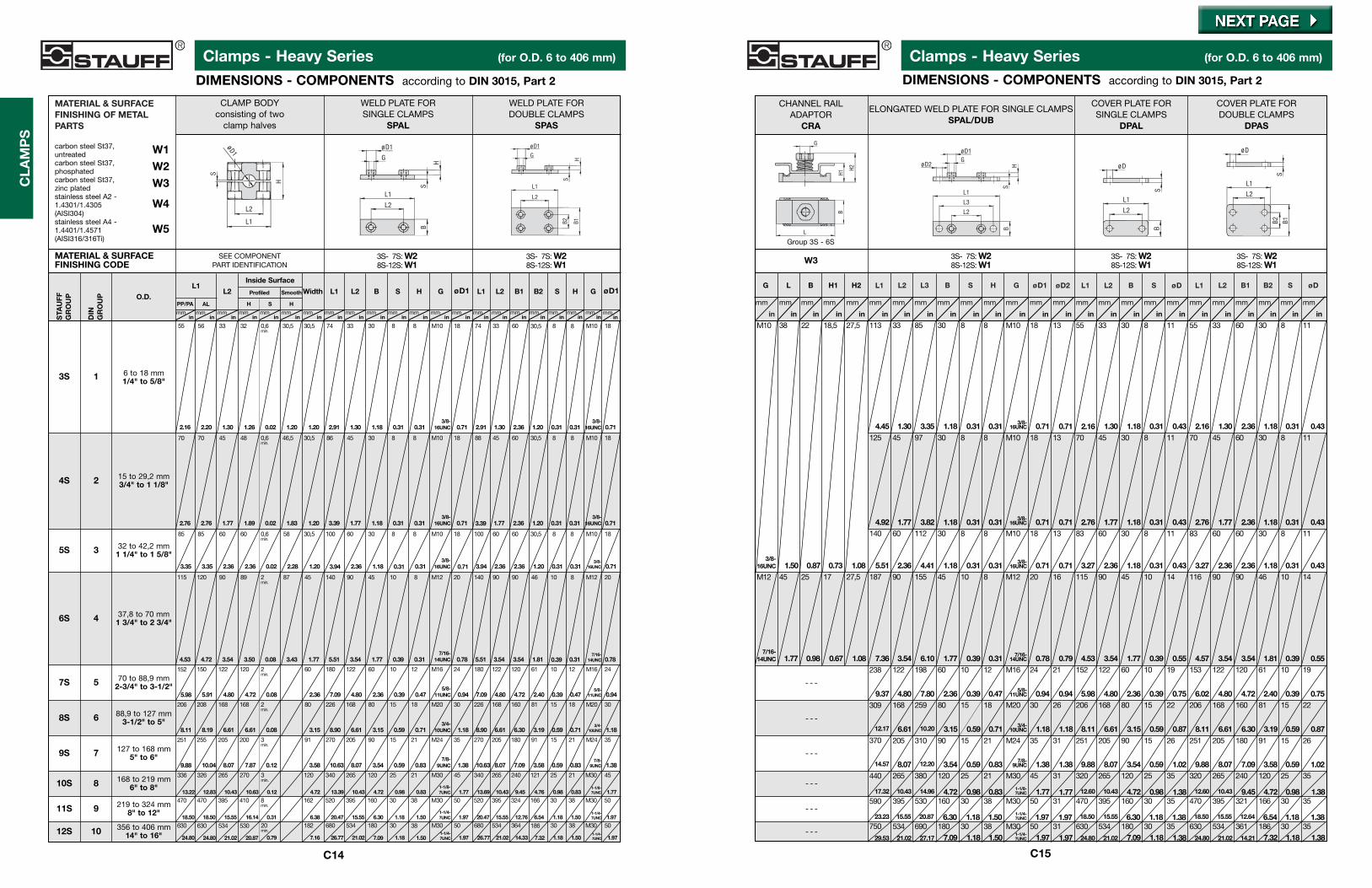
DIMENSIONS - COMPONENTS according to DIN 3015, Part 2
Clamps - Heavy Series (for O.D. 6 to 406 mm)
DIMENSIONS - COMPONENTS according to DIN 3015, Part 2
C14
CLA
MP
S
C15
W3 3S-07S: W28S-12S: W1
3S-07S: W28S-12S: W1
3S-07S: W28S-12S: W1
CHANNEL RAILADAPTOR
CRA
ELONGATED WELD PLATE FOR SINGLE CLAMPSSPAL/DUB
COVER PLATE FORSINGLE CLAMPS
DPAL
COVER PLATE FORDOUBLE CLAMPS
DPAS
G
H2
H1
L2
øD1
HB
S
L3
L1
øD2G
B
L2
øD
S
L1
B2
L2
B1
L1
øD
S
Group 3S - 6S
G L B H1 H2
L
B
L1 L2 L3 B S H G øD1 øD2 L1 L2 B S øD L1 L2 B1 B2 S øD
in
mm
in
mm
in
mm
in
mm
in
mm
in
mm
in
mm
in
mm
in
mm
in
mmmm
in
mm
in
mm
in
mm
in
mm
in
mm
in
mm
in
mm
in
mm
in
mm
in
mm
in
mm
in
mm
in
mm
in
mm
3/8-16UNC
M10
1.50 0.87 0.73 1.08
38 22 18,5 27,5 113 33 85 30 8 8
in
M10 18 13 55 33 30 8 11 55 33 60 30 8 11
4.45 1.30 3.35 1.18 0.31 0.31 0.71 0.71 2.16 1.30 1.18 0.31 0.43 2.16 1.30 2.36 1.18 0.31 0.43
1.18 1.387.3214.2121.0224.801.381.187.0921.0224.801.971.971-1/4-7UNC1.501.187.0927.1721.02
1.18 1.386.5412.6415.5518.501.381.186.3015.5518.501.971.971.501.186.3020.8715.55
0.98 1.384.729.4510.4312.601.380.984.7210.4312.601.771.770.830.984.7214.9610.43
8.07 12.20 3.54 0.59 0.83 1.38 1.38 9.88 8.07 3.54 0.59 1.02 9.88 8.07 7.09 3.58 0.59 1.02
6.61 10.20 3.15 0.59 0.71 1.18 1.18 8.11 6.61 3.15 0.59 0.87 8.11 6.61 6.30 3.19 0.59 0.87
4.80 7.80 2.36 0.39 0.47 0.94 0.94 5.98 4.80 2.36 0.39 0.75 6.02 4.80 4.72 2.40 0.39 0.75
3.54 6.10 1.77 0.39 0.31 0.78 0.79 4.53 3.54 1.77 0.39 0.55 4.57 3.54 3.54 1.81 0.39 0.55
2.36 4.41 1.18 0.31 0.31 0.71 0.71 3.27 2.36 1.18 0.31 0.43 3.27 2.36 2.36 1.18 0.31 0.43
1.77 3.82 1.18 0.31 0.71 0.71 2.76 1.77 1.18 0.31 0.43 2.76 1.77 2.36 1.18 0.31 0.43
1.77 0.98 0.67 1.08 7.36
5.51
4.92
- - -
- - -
- - -
- - -
- - -
125 45 97 30 8 8 M10 18 13 70 45 30 8 11 70 45 60 30 8 11
140 60 112 30 8 8 M10 18 13 83 60 30 8 11 83 60 60 30 8 11
187 90 155 45 10 8 M12 20 16 115 90 45 10 14 116 90 90 46 10 14
122 198 60 10 12 M16 24 21 152 122 60 10 19 153 122 120 61 10 19
168 259 80 15 18 M20 30 26 206 168 80 15 22 206 168 160 81 15 22
205 310 90 15 21 M24 35 31 251 205 90 15 26 251 205 180 91 15 26
265 380 120 25 21 M30 45 31 320 265 120 25 35 320 265 240 120 25 35
395 530 160 30 38 M30 50 31 470 395 160 30 35 470 395 321 166 30 35
534 690 180 30 38 M30 50 31 630 534 180 30 35 630 534 361 186 30 35
M12 45 25 17 27,5
7/16-14UNC
29.53
75023.23
59017.32
440
14.57
370
12.17
309
9.37
238
1-1/4-7UNC
1-1/8-7UNC
7/8-9UNC
3/4-10UNC
5/8-11UNC
7/16-14UNC
3/8-16UNC
3/8-16UNC0.31
3/8-16UNC
- - -
MATERIAL & SURFACEFINISHING CODE
O.D.
STA
UFF
GR
OU
P
DIN
GR
OU
P
4S
5S
6S
7S
8S
9S
10S
11S
1
2
3
4
5
6
7
8
9
6 to 18 mm1/4" to 5/8"
12S 10
CLAMP BODYconsisting of two
clamp halves
WELD PLATE FORSINGLE CLAMPS
SPAL
WELD PLATE FORDOUBLE CLAMPS
SPAS
SEE COMPONENTPART IDENTIFICATION
3S-07S: W28S-12S: W1
3S-07S: W28S-12S: W1
B
L2
øD1
G
H
L1
S
L2
øD1
L1S
H
L2
øD1
H
L1
B1B2S
G
MATERIAL & SURFACEFINISHING OF METALPARTS
carbon steel St37,untreated W1carbon steel St37,phosphated W2carbon steel St37,zinc plated W3stainless steel A2 - 1.4301/1.4305 W4(AISI304)stainless steel A4 - 1.4401/1.4571 W5(AISI316/316Ti)
15 to 29,2 mm3/4" to 1 1/8"
32 to 42,2 mm1 1/4" to 1 5/8"
37,8 to 70 mm1 3/4" to 2 3/4"
70 to 88,9 mm2-3/4" to 3-1/2"
88,9 to 127 mm3-1/2" to 5"
127 to 168 mm5" to 6"
168 to 219 mm6" to 8"
219 to 324 mm8" to 12"
356 to 406 mm14" to 16"
PP/PA AL
L1L2
H S H
Inside Surface
Profiled Smooth Width L1 L2 B S H G øD1 L1 L2 B1 B2 S H G øD1
inmm
in inmmmm mm
inin inmmmm
inmm mm
inmm
in inmm
inmmmm
in inmm
inmm
inmm
inmm
inmm
inmm mm
inmm
in inmm
inmm
2.16
55
2.20
56
1.30
33
1.26
32
0.02
0,6min.
1.20
30,5
1.20
30,5
2.91
74
1.30
33
1.18
30
0.31
8
0.31
8
3/8-16UNC
M10
0.71
18
2.91
74
1.30
33
2.36
60
1.20
30,5
0.31
8
0.31
8 M10
0.71
18
2.76
70
2.76
70
1.77
45
1.89
48
0.02
0,6min.
1.83
46,5
1.20
30,5
3.39
86
1.77
45
1.18
30
0.31
8
0.31
8 M10
0.71
18
3.39
88
1.77
45
2.36
60
1.20
30,5
0.31
8
0.31
8 M10
0.71
18
3.35
85
3.35
85
2.36
60
2.36
60
0.02
0,6min.
2.28
58
1.20
30,5
3.94
100
2.36
60
1.18
30
0.31
8
0.31
8 M10
0.71
18
3.94
100
2.36
60
2.36
60
1.20
30,5
0.31
8
0.31
8 M10
0.71
18
4.53
115
4.72
120
3.54
90
3.50
89
0.08
2min.
3.43
87
1.77
45
5.51
140
3.54
90
1.77
45
0.39
10
0.31
8 M12
0.78
20
5.51
140
3.54
90
3.54
90
1.81
46
0.39
10
0.31
8 M12
0.78
20
5.98
152
5.91
150
4.80
122
4.72
120
0.08
2min.
2.36
60
7.09
180
4.80
122
2.36
60
0.39
10
0.47
12 M16
0.94
24
7.09
180
4.80
122
4.72
120
2.40
61
0.39
10
0.47
12 M16
0.94
24
8.11
206
8.19
208
6.61
168
6.61
168
0.08
2min.
3.15
80
8.90
226
6.61
168
3.15
80
0.59
15
0.71
18 M20
1.18
30
8.90
226
6.61
168
6.30
160
3.19
81
0.59
15
0.71
18 M20
1.18
30
9.88
251
10.04
255
8.07
205
7.87
200
0.12
3min.
3.58
91
10.63
270
8.07
205
3.54
90
0.59
15
0.83
21 M24
1.38
35
10.63
270
8.07
205
7.09
180
3.58
91
0.59
15
0.83
21 M24
1.38
35
13.22
336
12.83
326
10.43
265
10.63
270
0.12
3min.
4.72
120
13.39
340
10.43
265
4.72
120
0.98
25
0.83
21 M30
1.77
45
13.69
340
10.43
265
9.45
240
4.76
121
0.98
25
0.83
21 M30
1.77
45
18.50
470
18.50
470
15.55
395
16.14
410
0.31
8min.
6.38
162
20.47
520
15.55
395
6.30
160
1.18
30
1.50
38 M30
1.97
50
20.47
520
15.55
395
12.76
324
6.54
166
1.18
30
1.50
38 M30
1.97
50
24.80
630
24.80
630
21.02
534
20.87
530
0.79
20min.
7.16
182
26.77
680
21.02
534
7.09
180
1.18
30
1.50
38 M30
1.97
50
26.77
680
21.02
534
14.33
364
7.32
186
1.18
30
1.50
38 M30
1.97
50
3/8-16UNC
3/8-16UNC
7/16-14UNC
5/8-11UNC
3/4-10UNC
7/8-9UNC
1-1/8-7UNC
1-1/4-7UNC
1-1/4-7UNC
3/8-16UNC
3/8-16UNC
3/8-16UNC
7/16-14UNC
5/8-11UNC
3/4-10UNC
7/8-9UNC
1-1/8-7UNC
1-1/4-7UNC
1-1/4-7UNC
3S
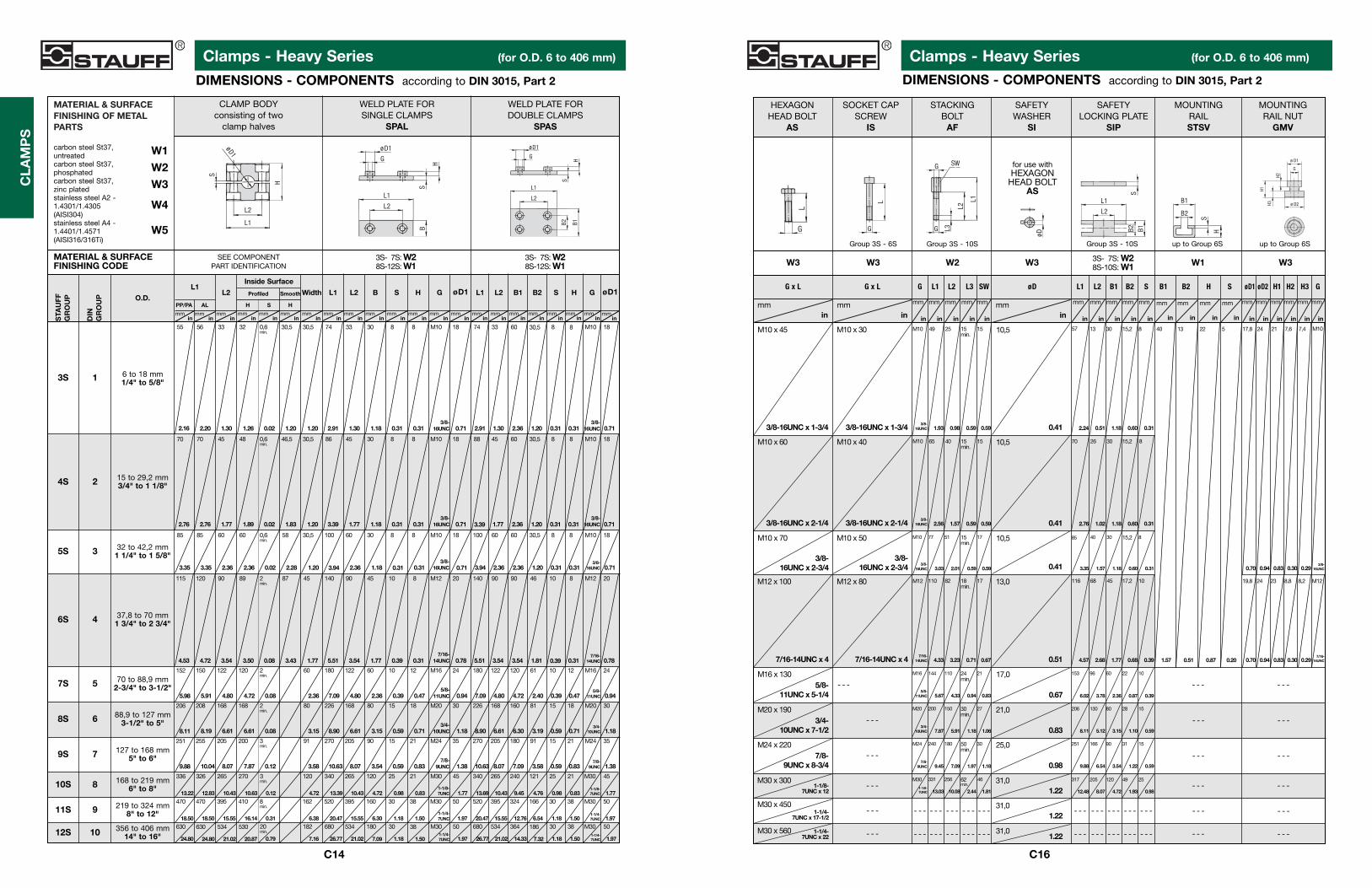
Clamps - Heavy Series (for O.D. 6 to 406 mm)
DIMENSIONS - COMPONENTS according to DIN 3015, Part 2
Clamps - Heavy Series (for O.D. 6 to 406 mm)
DIMENSIONS - COMPONENTS according to DIN 3015, Part 2
C14
CLA
MP
S
C16
W3 W3 W2 W3 3S-07S: W28S-10S: W1 W1 W3
HEXAGONHEAD BOLT
AS
SOCKET CAPSCREW
IS
STACKINGBOLT
AF
SAFETYWASHER
SI
SAFETYLOCKING PLATE
SIP
MOUNTINGRAILSTSV
MOUNTINGRAIL NUT
GMV
L2
SW
L3
L1
G
G
ø D1
G
H2
H1
H3 ø D2
Group 3S - 6S Group 3S - 10S up to Group 6S up to Group 6S
for use withHEXAGON
HEAD BOLTAS
B1 B2 H S øD1 øD2 H1 H2 H3 GL1 L2 B1 B2 SøDG L1 L2 L3 SWG x L G x L
L
G
L
G
øD
L2
SB2 B1
L1
S
B1
H
B2
- - - - - -
- - -- - -
- - - - - -
- - -- - -
- - -- - -
- - - - - -- - -
- - -
- - -
- - -
- - -
- - -
inmm
inmm
inmm
in
mm
in
mm
in
mm
in
mm
in
mm
in
mm
in
mm
in in
mmmm
in
mm
in
mm
in
mm
in
mm
in
mm
in
mm
in
mm
in
mm
in
mm
in
mm
in
mm
3/8-16UNC x 1-3/4
M10 x 45 M10 x 30
M10 x 60 M10 x 40
M10 x 70 M10 x 50
M12 x 100 M12 x 80
M16 x 130
M20 x 190
M24 x 220
M30 x 300
M30 x 450
M30 x 560
- - - - - - - - - - - - - - -
- - -- - -- - -- - -- - -
- - - - - - - - - - - - - - -
- - -- - -- - -- - -- - -
3/8-16UNC
M10
1.93
49
0.98
25
0.59
15min.
0.59
15
M10
2.56
65
1.57
40
0.59
15min.
0.59
15
M10
3.03
77
2.01
51
0.59
15min.
0.59
17
M16
5.67
144
4.33
110
0.94
24min.
0.83
21
M20
7.87
200
5.91
150
1.18
30min.
1.06
27
1.18
30
1.97
50min.
7.09
180
9.45
240M24
M30
13.03
331
10.08
256
2.44
62min.
1.81
46
0.41
10,5
0.41
10,5
0.41
10,5
0.51
13,0
0.67
17,0
0.83
21,0
0.98
25,0
1.2231,0
1.2231,0
1.2231,0
2.24
57
0.51
13
1.18
30
0.60
15,2
0.31
8
0.31
8
0.60
15,2
1.18
30
1.02
26
2.76
70
0.67
17
0.71
18min.
3.23
82
4.33
110M12
4.57
116
2.68
68
1.77
45
0.68
17,2
0.39
10
1.57
40
0.51
13
0.87
22
0.20
5
0.70
17,8
0.94
24
0.83
21
0.30
7,6
0.29
7,4 M10
0.70
19,8
0.94
24
0.83
23
0.30
8,8
0.29
8,2
7/16-14UNC
M12
6.02
153
3.78
96
2.36
60
0.87
22
0.39
10
8.11
206
5.12
130
3.15
80
1.10
28
0.59
15
3.35
85
1.57
40
1.18
30
0.60
15,2
0.31
8
0.59
15
1.22
31
3.54
90
6.54
166
9.88
251
12.48
317
8.07
205
4.72
120
1.93
49
0.98
25
3/8-16UNC x 2-1/4
3/8-16UNC x 2-3/4
7/16-14UNC x 4
5/8-11UNC x 5-1/4
3/4-10UNC x 7-1/2
7/8-9UNC x 8-3/4
1-1/8-7UNC x 12
1-1/4-7UNC x 17-1/2
1-1/4-7UNC x 22
7/16-14UNC x 4
3/8-16UNC x 2-3/4
3/8-16UNC x 2-1/4
3/8-16UNC x 1-3/4
3/8-16UNC
1-1/8-7UNC
3/8-16UNC
7/16-14UNC
5/8-11UNC
3/4-10UNC
7/8-9UNC
3/8-16UNC
Group 3S - 10S
MATERIAL & SURFACEFINISHING CODE
O.D.
STA
UFF
GR
OU
P
DIN
GR
OU
P
4S
5S
6S
7S
8S
9S
10S
11S
1
2
3
4
5
6
7
8
9
6 to 18 mm1/4" to 5/8"
12S 10
CLAMP BODYconsisting of two
clamp halves
WELD PLATE FORSINGLE CLAMPS
SPAL
WELD PLATE FORDOUBLE CLAMPS
SPAS
SEE COMPONENTPART IDENTIFICATION
3S-07S: W28S-12S: W1
3S-07S: W28S-12S: W1
B
L2
øD1
G
H
L1
S
L2
øD1
L1
S
H
L2
øD1
H
L1
B1B2S
G
MATERIAL & SURFACEFINISHING OF METALPARTS
carbon steel St37,untreated W1carbon steel St37,phosphated W2carbon steel St37,zinc plated W3stainless steel A2 - 1.4301/1.4305 W4(AISI304)stainless steel A4 - 1.4401/1.4571 W5(AISI316/316Ti)
15 to 29,2 mm3/4" to 1 1/8"
32 to 42,2 mm1 1/4" to 1 5/8"
37,8 to 70 mm1 3/4" to 2 3/4"
70 to 88,9 mm2-3/4" to 3-1/2"
88,9 to 127 mm3-1/2" to 5"
127 to 168 mm5" to 6"
168 to 219 mm6" to 8"
219 to 324 mm8" to 12"
356 to 406 mm14" to 16"
PP/PA AL
L1L2
H S H
Inside Surface
Profiled Smooth Width L1 L2 B S H G øD1 L1 L2 B1 B2 S H G øD1
inmm
in inmmmm mm
inin inmmmm
inmm mm
inmm
in inmm
inmmmm
in inmm
inmm
inmm
inmm
inmm
inmm mm
inmm
in inmm
inmm
2.16
55
2.20
56
1.30
33
1.26
32
0.02
0,6min.
1.20
30,5
1.20
30,5
2.91
74
1.30
33
1.18
30
0.31
8
0.31
8
3/8-16UNC
M10
0.71
18
2.91
74
1.30
33
2.36
60
1.20
30,5
0.31
8
0.31
8 M10
0.71
18
2.76
70
2.76
70
1.77
45
1.89
48
0.02
0,6min.
1.83
46,5
1.20
30,5
3.39
86
1.77
45
1.18
30
0.31
8
0.31
8 M10
0.71
18
3.39
88
1.77
45
2.36
60
1.20
30,5
0.31
8
0.31
8 M10
0.71
18
3.35
85
3.35
85
2.36
60
2.36
60
0.02
0,6min.
2.28
58
1.20
30,5
3.94
100
2.36
60
1.18
30
0.31
8
0.31
8 M10
0.71
18
3.94
100
2.36
60
2.36
60
1.20
30,5
0.31
8
0.31
8 M10
0.71
18
4.53
115
4.72
120
3.54
90
3.50
89
0.08
2min.
3.43
87
1.77
45
5.51
140
3.54
90
1.77
45
0.39
10
0.31
8 M12
0.78
20
5.51
140
3.54
90
3.54
90
1.81
46
0.39
10
0.31
8 M12
0.78
20
5.98
152
5.91
150
4.80
122
4.72
120
0.08
2min.
2.36
60
7.09
180
4.80
122
2.36
60
0.39
10
0.47
12 M16
0.94
24
7.09
180
4.80
122
4.72
120
2.40
61
0.39
10
0.47
12 M16
0.94
24
8.11
206
8.19
208
6.61
168
6.61
168
0.08
2min.
3.15
80
8.90
226
6.61
168
3.15
80
0.59
15
0.71
18 M20
1.18
30
8.90
226
6.61
168
6.30
160
3.19
81
0.59
15
0.71
18 M20
1.18
30
9.88
251
10.04
255
8.07
205
7.87
200
0.12
3min.
3.58
91
10.63
270
8.07
205
3.54
90
0.59
15
0.83
21 M24
1.38
35
10.63
270
8.07
205
7.09
180
3.58
91
0.59
15
0.83
21 M24
1.38
35
13.22
336
12.83
326
10.43
265
10.63
270
0.12
3min.
4.72
120
13.39
340
10.43
265
4.72
120
0.98
25
0.83
21 M30
1.77
45
13.69
340
10.43
265
9.45
240
4.76
121
0.98
25
0.83
21 M30
1.77
45
18.50
470
18.50
470
15.55
395
16.14
410
0.31
8min.
6.38
162
20.47
520
15.55
395
6.30
160
1.18
30
1.50
38 M30
1.97
50
20.47
520
15.55
395
12.76
324
6.54
166
1.18
30
1.50
38 M30
1.97
50
24.80
630
24.80
630
21.02
534
20.87
530
0.79
20min.
7.16
182
26.77
680
21.02
534
7.09
180
1.18
30
1.50
38 M30
1.97
50
26.77
680
21.02
534
14.33
364
7.32
186
1.18
30
1.50
38 M30
1.97
50
3/8-16UNC
3/8-16UNC
7/16-14UNC
5/8-11UNC
3/4-10UNC
7/8-9UNC
1-1/8-7UNC
1-1/4-7UNC
1-1/4-7UNC
3/8-16UNC
3/8-16UNC
3/8-16UNC
7/16-14UNC
5/8-11UNC
3/4-10UNC
7/8-9UNC
1-1/8-7UNC
1-1/4-7UNC
1-1/4-7UNC
3S

Pipe Clamps - Heavy Series (for O.D. 6 to 406 mm)
ORDER CODES - COMPLETE CLAMPS according to DIN 3015, Part 2
Clamps - Heavy Series (for O.D. 6 to 406 mm)
ORDER CODES - COMPLETE CLAMPS according to DIN 3015, Part 2
C17 C18
TYPE OFINSTALLATION *11
no code without mounting plate,rail adaptor or rail nuts
SPAL Weld Plate for Single Clamps
SPAS Weld Plate for Double Clamps
SPAL/DUB Elongated Weld Plate for Single Clamps
CRA *2 *3 Channel Rail Adaptor
GMV *2 Mounting Rail Nut
❶ MOUNTING & FITTINGCOMBINATION *11
DPAS - IS Cover Plate / Socket Cap Screw
IS *2 Socket Cap Screw
SIP - AF *4 Safety Locking Plate /Stacking Bolt
❹MATERIAL & DESIGNOF CLAMP BODY *1
AL Aluminium, profiled inside, with tension clearance
PP Polypropylene, profiled inside, with tension clearance
PPH*2 Polypropylene, smooth inside,without tension clearance
PA Polyamide, profiled inside, with tension clearance
PAH*2 Polyamide, smooth inside, without tension clearance
SA*10 Santoprene, profiled inside, with tension clearance
SAH*10 Santoprene, smooth inside, without tension clearance
❸
no code components supplied separately (standard)
A assembled (optional)
K packed in kits (optional)
❼
TYPE OFTHREAD *5
M Metric Thread
U UNC Thread
❺ MATERIAL & SURFACEFINISHING OFMETAL PARTS *6
❻
ASSEMBLING &PACKAGING
❶ ❷ ❸ ❹ ❺ ❻✱ ✱ ✱ ✱ ✱ ✱ ✱ ✱,✱ ✱ ✱ ✱ ✱ ✱ ✱ ✱ - ✱ ✱ ✱ W ✱ ✱ ❼ ✱
W2 all parts are phosphated
W3 all parts are zinc plated
W4 all metal parts made of stain-less steel A2 - 1.4301/1.4305 (AISI 304)
W5 all metal parts made of stain-less steel A4 - 1.4401/1.4571 (AISI 316/316Ti)
W10 weld plate phosphated,all other parts zinc plated
W12 weld plate and cover plate phosphated, bolts untreated
W13 rail nut zinc plated, cover plate phosphated, bolts untreated
W15 weld plate and cover plate phosphated, bolts zinc plated
W1 all parts are untreated
STAUFF GROUP &SIZE OF CLAMP BODY
STAUFF GROUP &SIZE OF CLAMP BODYCONTINUATION
Gro
up
Tube
O.D
.in
mm
Tube
O.D
.in
inch Material Code
Clamp Body(both halves)N
omin
al
Bor
e P
ipe
Hos
e
37,8 1 6037,842,2 11/4 6042,244,5 13/4 6044,548,3 11/2 6048,348,4 11/4 6048,450,8 2 6050,854,4 11/2 6054,457,2 21/4 6057,260,3 2 6060,363,5 21/2 6063,570 23/4 607070 23/4 707073 21/2 707376,2 3 21/2 7076,288,9 31/2 3 7088,988,9 31/2 3 8088,9102 4 31/2 8102114 41/2 4 8114127 5 8127127 5 9127140 5 9140152 6 9152168 6 9168168 6 10168203 10203219 8 10219219 8 11219273 10 11273324 12 11324356 14 12356406 16 12406
STA
UFF
6S
DIN
4
❷
ST.
7S
D
IN5
ST.
8S
D
IN6
ST.
9S
D
IN 7
SF.
10S
DIN
8S
T. 1
1SD
IN 9
12S
10
*7*7*7
*8
*9
*7
Gro
up
Tube
O.D
.in
mm
Tube
O.D
.in
inch Material Code
Clamp Body(both halves)N
omin
al
Bor
e P
ipe
Hos
e
6 30066,4 1/4 3006,48 30089,5 3/8 3009,5
10 1/8 301012 301212,7 1/2 3012,713,7 1/4 3013,714 301415 301516 5/8 301617,1 3/8 3017,118 301815 1/4 401519 3/4 401919,8 3/8 4019,820 402021,3 1/2 4021,322,1 1/2 4022,122,2 7/8 4022,225,1 5/8 4025,125,4 1 4025,426,7 3/4 4026,729,2 3/4 4029,232 11/4 503233,4 1 5033,438 11/2 503840 504042,2 11/4 5042,2
TECHNICAL NOTES
*1 SEE MATERIAL PROPERTIES ON PAGE C52. OTHER CLAMP BODY MATERIALS AND COLORS ARE AVAILABLE UPONREQUEST.
*2 AVAILABLE UP TO STAUFF GROUP 6S ONLY
*3 SPECIAL LENGTH BOLTS REQUIRED. SUPPLIED WHEN ORDERED AS KITS.
*4 AVAILABLE FOR STAUFF GROUP 3S TO 10S ONLY
*5 PLEASE NOTE THAT YOU HAVE TO SPECIFY THREAD TYPE.
*6 INDIVIDUAL COMBINATIONS OF ALTERNATIVE SURFACE FINISHINGS AND SPECIAL PROPERTY MATERIALS AREAVAILABLE UPON REQUEST.
*7 CLAMPS WILL BE SMOOTH INSIDE AND WITHOUT TENSION CLEARANCE.
*8 ACCORDING TO ANSI B 36-10.
*9 OTHER STANDARDS.
*10 SA AND SAH ARE SPECIAL ORDER MATERIALS AND ONLY AVAILABLE UP TO STAUFF GROUP 6S ONLY. CONTACTFACTORY FOR FURTHER INFORMATION.
*11 METAL PARTS ARE UNTREATED FOR STAUFF GROUPS 8S TO 12S.
W16 rail nut zinc plated, cover plate phosphated, bolts zinc plated
W17 safety locking plate phosphated, stacking bolts zinc plated
DPAS - AS Double Cover Plate / Hexagon Head Bolt
DPAL - AS Single Cover Plate / Hexagon Head Bolt
STA
UFF
3S
DIN
1
❷
STA
UFF
4S
DIN
2S
TAU
FF 5
SD
IN 3
*7
*7
*7
*7
*7
W18 safety locking plate untreated, stacking bolts phosphated
2x Hexagon Head BoltSurface: W3, Zinc PlatedThread: UNC
1x Cover Plate for Single ClampsSurface: W2, phosphated
1x Clamp (two halves)Material: PolypropyleneDesign: profiled inside,
with tension clearance
Group: STAUFF 3S / DIN 1Tube-O.D. 6 mm / 0.24”
1x Weld Plate for Single ClampsSurface: W2, phosphatedThread: UNC
W15 (up to Group 7S) or W1(Group 8S to 12S) are standards for this type of installation.
SPAL 3006 PP DPAL-AS U W15
4x Hexagon Head BoltSurface: W3, Zinc PlatedThread: UNC
1x Cover Plate for Double ClampsSurface: W2, phosphated
2x Clamp (two halves)Material: PolypropyleneDesign: profiled inside,
with tension clearance
Group: STAUFF 3S / DIN 1Tube-O.D. 6 mm / 0.24”
1x Weld Plate for Double ClampsSurface: W2, phosphatedThread: UNC
W15 (up to Group 7S) or W1(Group 8S to 12S) are standards for this type of installation.
SPAS 3006 PP DPAS-AS U W15
2x Hexagon Head BoltSurface: W3, Zinc PlatedThread: UNC
1x Cover Plate for Single ClampsSurface: W2, phosphated
1x Clamp (two halves)Material: PolypropyleneDesign: profiled inside,
with tension clearance
Group: STAUFF 3S / DIN 1Tube-O.D. 6 mm / 0.24”
1x Elongated Weld Plate for Single ClampsSurface: W2, phosphatedThread: UNC
W15 (up to Group 7S) or W1(Group 8S to 12S) are standards for this type of installation.
SPAL/DUB 3006 PP DPAL-AS U W15
2x Socket Cap ScrewSurface: W3, Zinc PlatedThread: UNC
1x Clamp (two halves)Material: PolypropyleneDesign: profiled inside,
with tension clearance
Group: STAUFF 3S / DIN 1Tube-O.D. 6 mm / 0.24”
1x Weld Plate for Single ClampsSurface: W2, phosphatedThread: UNC
W10 (up to Group 6S) is standardfor this type of installation. Thiscombination is available up togroup 6S only.
SPAL 3006 PP IS U W10

Clamps - Heavy Series (for O.D. 6 to 406 mm)
ORDER CODES - COMPLETE CLAMPS according to DIN 3015, Part 2
Clamps - Heavy Series (for O.D. 6 to 406 mm)
ORDER CODES - COMPLETE CLAMPS according to DIN 3015, Part 2
C19
CLA
MP
S
C17
TYPE OFINSTALLATION *11
no code without mounting plate,rail adaptor or rail nuts
SPAL Weld Plate for Single Clamps
SPAS Weld Plate for Double Clamps
SPAL/DUB Elongated Weld Plate for Single Clamps
CRA *2 *3 Channel Rail Adaptor
GMV *2 Mounting Rail Nut
❶ MOUNTING & FITTINGCOMBINATION *11
DPAS - IS Cover Plate / Socket Cap Screw
IS *2 Socket Cap Screw
SIP - AF *4 Safety Locking Plate /Stacking Bolt
❹MATERIAL & DESIGNOF CLAMP BODY *1
AL Aluminium, profiled inside, with tension clearance
PP Polypropylene, profiled inside, with tension clearance
PPH*2 Polypropylene, smooth inside,without tension clearance
PA Polyamide, profiled inside, with tension clearance
PAH*2 Polyamide, smooth inside, without tension clearance
SA*10 Santoprene, profiled inside, with tension clearance
SAH*10 Santoprene, smooth inside, without tension clearance
❸
no code components supplied separately (standard)
A assembled (optional)
K packed in kits (optional)
❼
TYPE OFTHREAD *5
M Metric Thread
U UNC Thread
❺ MATERIAL & SURFACEFINISHING OFMETAL PARTS *6
❻
ASSEMBLING &PACKAGING
❶ ❷ ❸ ❹ ❺ ❻✱ ✱ ✱ ✱ ✱ ✱ ✱ ✱,✱ ✱ ✱ ✱ ✱ ✱ ✱ ✱ - ✱ ✱ ✱ W ✱ ✱ ❼ ✱
W2 all parts are phosphated
W3 all parts are zinc plated
W4 all metal parts made of stain-less steel A2 - 1.4301/1.4305 (AISI 304)
W5 all metal parts made of stain-less steel A4 - 1.4401/1.4571 (AISI 316/316Ti)
W10 weld plate phosphated,all other parts zinc plated
W12 weld plate and cover plate phosphated, bolts untreated
W13 rail nut zinc plated, cover plate phosphated, bolts untreated
W15 weld plate and cover plate phosphated, bolts zinc plated
W1 all parts are untreated
STAUFF GROUP &SIZE OF CLAMP BODY
STAUFF GROUP &SIZE OF CLAMP BODYCONTINUATION
Gro
up
Tube
O.D
.in
mm
Tube
O.D
.in
inch Material Code
Clamp Body(both halves)N
omin
al
Bor
e P
ipe
Hos
e
37,8 1 6037,842,2 11/4 6042,244,5 13/4 6044,548,3 11/2 6048,348,4 11/4 6048,450,8 2 6050,854,4 11/2 6054,457,2 21/4 6057,260,3 2 6060,363,5 21/2 6063,570 23/4 607070 23/4 707073 21/2 707376,2 3 21/2 7076,288,9 31/2 3 7088,988,9 31/2 3 8088,9102 4 31/2 8102114 41/2 4 8114127 5 8127127 5 9127140 5 9140152 6 9152168 6 9168168 6 10168203 10203219 8 10219219 8 11219273 10 11273324 12 11324356 14 12356406 16 12406
STA
UFF
6S
DIN
4
❷
ST.
7S
D
IN5
ST.
8S
D
IN6
ST.
9S
D
IN 7
SF.
10S
DIN
8S
T. 1
1SD
IN 9
12S
10
*7*7*7
*8
*9
*7
Gro
up
Tube
O.D
.in
mm
Tube
O.D
.in
inch Material Code
Clamp Body(both halves)N
omin
al
Bor
e P
ipe
Hos
e
6 30066,4 1/4 3006,48 30089,5 3/8 3009,5
10 1/8 301012 301212,7 1/2 3012,713,7 1/4 3013,714 301415 301516 5/8 301617,1 3/8 3017,118 301815 1/4 401519 3/4 401919,8 3/8 4019,820 402021,3 1/2 4021,322,1 1/2 4022,122,2 7/8 4022,225,1 5/8 4025,125,4 1 4025,426,7 3/4 4026,729,2 3/4 4029,232 11/4 503233,4 1 5033,438 11/2 503840 504042,2 11/4 5042,2
TECHNICAL NOTES
*1 SEE MATERIAL PROPERTIES ON PAGE C52. OTHER CLAMP BODY MATERIALS AND COLORS ARE AVAILABLE UPONREQUEST.
*2 AVAILABLE UP TO STAUFF GROUP 6S ONLY
*3 SPECIAL LENGTH BOLTS REQUIRED. SUPPLIED WHEN ORDERED AS KITS.
*4 AVAILABLE FOR STAUFF GROUP 3S TO 10S ONLY
*5 PLEASE NOTE THAT YOU HAVE TO SPECIFY THREAD TYPE.
*6 INDIVIDUAL COMBINATIONS OF ALTERNATIVE SURFACE FINISHINGS AND SPECIAL PROPERTY MATERIALS AREAVAILABLE UPON REQUEST.
*7 CLAMPS WILL BE SMOOTH INSIDE AND WITHOUT TENSION CLEARANCE.
*8 ACCORDING TO ANSI B 36-10.
*9 OTHER STANDARDS.
*10 SA AND SAH ARE SPECIAL ORDER MATERIALS AND ONLY AVAILABLE UP TO STAUFF GROUP 6S ONLY. CONTACTFACTORY FOR FURTHER INFORMATION.
*11 METAL PARTS ARE UNTREATED FOR STAUFF GROUPS 8S TO 12S.
W16 rail nut zinc plated, cover plate phosphated, bolts zinc plated
W17 safety locking plate phosphated, stacking bolts zinc plated
DPAS - AS Double Cover Plate / Hexagon Head Bolt
DPAL - AS Single Cover Plate / Hexagon Head Bolt
STA
UFF
3S
DIN
1
❷
STA
UFF
4S
DIN
2S
TAU
FF 5
SD
IN 3
*7
*7
*7
*7
*7
W18 safety locking plate untreated, stacking bolts phosphated
NOTES REGARDING THE USE OFTHE CHANNEL RAIL ADAPTOR CRA
The CHANNEL RAIL ADAPTOR Type CRA is suitable for the following channel rails:
UNISTRUT-RailsP1000, P1000T, P1000V, P1000VT, P1001P2000, P2000TP3003, P3003T, P3300V, P3300VT, P3301P4000, P4000TP5000, P5000T, P5001, P5500, P5500T, P5501
STAUFF-RailsSCS-048-1-PL, SCS-120-1-PL, SCS-048-1-GR, SCS-120-1-GR(see page C42 for details)
HALFEN-RailsHM 41/41HZA 41/22HZM 41/41HZM 41/22HL 41/41, HL 41/B2
2x Stacking BoltSurface: W3, Zinc PlatedThread: UNC
1x Safety Locking plateSurface: W2, phosphated
1x Clamp (two halves)Material: PolypropyleneDesign: profiled inside,
with tension clearance
Group: STAUFF 3S / DIN 1Tube-O.D. 6 mm / 0.24"
W17 (up to Group 7S) or W18(Group 8S to 10S) are standards for this type of installation.
3006 PP SIP-AF U W17
2x Hexagon Head BoltSurface: W3, Zinc PlatedThread: UNC
1x Cover Plate for Single ClampsSurface: W2, phosphated
1x Clamp (two halves)Material: PolypropyleneDesign: profiled inside,
with tension clearance
Group: STAUFF 3S / DIN 1Tube-O.D. 6 mm / 0.24"
2x Mounting Rail NutSurface: W3, Zinc PlatedThread: UNC
W16 (up to Group 6S) is standard for this type of installation. Thiscombination is available up to Group 6S only.
GMV 3006 PP DPAL-AS U W16
2x Hexagon Head BoltSurface: W3, Zinc PlatedThread: UNC
1x Cover Plate for Single ClampsSurface: W2, phosphated
1x Clamp (two halves)Material: PolypropyleneDesign: smooth inside,
without tension clearance
Group: STAUFF 3S / DIN 1Hose-O.D. 6 mm / 0.24"
1x Weld Plate for Single ClampsSurface: W2, phosphatedThread: UNC
W15 (up to Group 6S) is standard forthis type of installation. Thiscombination is available up to Group6S only.
SPAL 3006 PPH DPAL-AS U W15

C20
Clamps - Twin Series (for O.D. 6 to 42 mm)
ORDER CODES - COMPONENTS according to DIN 3015, Part 3
CLA
MP
S
CLAMP BODYconsisting of two
clamp halves
SINGLEWELD PLATE
SP
GROUP WELDPLATERAP
CHANNEL RAILADAPTOR
CRA
MATERIAL & SURFACE FINISHING CODE(ALL DISPLAYED OPTIONS ARE STANDARD DELIVERY)
SEE COMPONENTPART IDENTIFICATION W2 W1 W3
6 106/06 ✱✱✱
6,4 1/4 106,4/06,4 ✱✱✱
8 5/16 108/08 ✱✱✱
9,5 3/8 109,5/09,5 ✱✱✱
10 1/8 110/10 ✱✱✱
12 112/12 ✱✱✱
12,7 1/2 212,7/12,7 ✱✱✱
13,5 1/4 213,5/13,5 ✱✱✱
14 214/14 ✱✱✱
15 215/15 ✱✱✱
16 5/8 216/16 ✱✱✱
17,2 3/8 217,2/17,2 ✱✱✱
18 218/18 ✱✱✱
19 3/4 319/19 ✱✱✱
20 320/20 ✱✱✱
21,3 1/2 321,3/21,3 ✱✱✱
22 7/8 322/22 ✱✱✱
25 325/25 ✱✱✱
25,4 1 325,4/25,4 ✱✱✱
26,9 3/4 426,9/26,9 ✱✱✱
28 428/28 ✱✱✱
30 430/30 ✱✱✱
32 532/32 ✱✱✱
33,7 533,7/33,7 ✱✱✱
35 535/35 ✱✱✱
38 538/38 ✱✱✱
40 540/40 ✱✱✱
42 542/42 ✱✱✱
ORDERING INFORMATION ✱✱✱ ,✱/✱✱ ,✱ ✱✱✱ SP ✱✱ ✱ ✱✱ CRA ✱✱ ✱ ✱✱
OU
TS
IDE
DIA
ME
TE
R
PIP
E /
TU
BE
/ H
OS
E
INM
M
STA
UFF
GR
OU
P
NO
MIN
AL
BO
RE
PIP
E
ININ
CH
DIN
GR
OU
P
OU
TS
IDE
DIA
ME
TE
R
PIP
E /
TU
BE
/ H
OS
E
ININ
CH
STAU
FFGR
OUP
OUTS
IDE
DIAM
ETER
SOF
BOTH
PIP
ESIN
MM
MAT
ERIA
L &
DESI
GNOF
CLAM
PBO
DY
STAU
FFGR
OUP
SING
LEW
ELD
PLAT
ESP
TYPE
OFTH
READ
MAT
ERIA
L&
SURF
ACE
FIN-
ISHI
NG
TYPE
OFTH
READ
CHAN
NEL
RAIL
AD
APTO
RCR
A
MAT
ERIA
L&
SURF
ACE
FIN-
ISHI
NG
1D
2D
3D
4D
5D
1
2
3
4
5
CRA 1-8/1D ✱ ✱✱for use with bolt
1/4 - 20UNC x 1 LG
CRA 2-3 D ✱ ✱✱for use with bolt
5/16 - 18UNC x 1-3/8 LG
CRA 2-3 D ✱ ✱✱for use with bolt
5/16 - 18UNC x 1-3/4 LG
CRA 4-5D ✱ ✱✱for use with bolt
5/16 - 18UNC x 2 LG
CRA 4-5D ✱ ✱✱for use with bolt
5/16 - 18UNC x 2-1/2 LG
RAP 1D/40/5 ✱ ✱✱
RAP 2D/58/5 ✱ ✱✱
RAP 3D/72/5 ✱ ✱✱
RAP 4D/90/5 ✱ ✱✱
RAP 5D/112/5 ✱ ✱✱
SP 1D ✱ ✱✱
SP 2D ✱ ✱✱
SP 3D ✱ ✱✱
SP 4D ✱ ✱✱
SP 5D ✱ ✱✱
STAU
FFGR
OUP
COMPONENT PART IDENTIFICATION FOR TWIN SERIES CLAMP BODIES AND COMPONENTS
CLAMP BODY
MATERIAL DESIGN COLOR CODE
Polypropylene profiled inside, greenwith tension clearance PP
Polypropylene smooth inside, greenwithout tension clearance PPH
MATERIAL DESIGN COLOR CODE
Polyamide profiled inside, blackwith tension clearance PA
Polyamide smooth inside, blackwithout tension clearance PAH
Alternative materials, designs and colors in addition to the above stated standard are available upon request.
suitable for severaltypes of channel rails,
see page C25
ALSO AVAILABLE
Extensive range of special clamping systems andaccessories, e.g. for noise and vibration reduced installation, for electric sensors and cables or for particular mounting purposes
see pages C26 to C31
Custom designed pipe clamps (machined and injectionmolded versions) according to customer`s specifications orbased on STAUFF developments
see pages C32 to C33
RAP ✱✱/✱✱/✱ ✱ ✱✱
GROU
PW
ELD
PLAT
ERA
P
STAU
FFGR
OUP
PIPE
CENT
ERSP
ACIN
G
NUM
BER
OFCL
AMPS
MAT
ERIA
L &
SURF
ACE
FINI
SHIN
G
TYPE
OFTH
READ
Consult factory for available hose sizes.

C21
Clamps - Twin Series (for O.D. 6 to 42 mm)
ORDER CODES - COMPONENTS according to DIN 3015, Part 3
CLA
MP
S
COVERPLATE
GD
HEXAGONHEAD BOLT
AS
STACKINGBOLT
AF
SAFETYLOCKING PLATE
SI
SAFETYLOCKING PLATE
SIV
MOUNTINGRAILTS
HEXAGONRAIL NUT
SM
W3 W3 W3 W3 W3 W1 W3
for multi-levelassembly, preventsupper clamp from
turning SM 1-8/1D
SM 2-5D
GD 1D ✱✱
GD 2D ✱✱
GD 3D ✱✱
GD 4D ✱✱
GD 5D ✱✱
AS 1D ✱ ✱✱
AS 2D ✱ ✱✱
AS 3D ✱ ✱✱
AS 4D ✱ ✱✱
AS 5D ✱ ✱✱
AF 1D ✱ ✱✱
AF 2D ✱ ✱✱
AF 3D ✱ ✱✱
AF 4D ✱ ✱✱
AF 5D ✱ ✱✱
SI 1D ✱✱
SI 2-5D ✱✱
SM 1-8/1D ✱ ✱✱
SM 2-5D ✱ ✱✱
SIV 1D ✱✱
SIV 2-3D ✱✱
TS ✱✱-✱ ✱✱
available heights: 11, 14 and 30 mm
0.43", 0.55" and 1.18"
available lengths:1m and 2 m
3.28’ and 6.56’
SIV 2-3D ✱✱
SIV 2-3D ✱✱
GD ✱✱ ✱✱
COVE
RPL
ATE
GD
MAT
ERIA
L&
SURF
ACE
FIN-
ISHI
NG
STAU
FFGR
OUP
AS ✱✱ ✱ ✱✱
HEXA
GON
HEAD
BOLT
AS
STAU
FFGR
OUP
MAT
ERIA
L&
SURF
ACE
FIN-
ISHI
NG
TYPE
OFTH
READ
AF ✱✱ ✱ ✱✱
STAC
KING
BOLT
AF
STAU
FFGR
OUP
MAT
ERIA
L&
SURF
ACE
FIN-
ISHI
NG
TYPE
OFTH
READ
SI ✱✱✱✱ ✱✱
SAFE
TYLO
CKIN
GPL
ATE
SI
MAT
ERIA
L&
SURF
ACE
FIN-
ISHI
NG
STAU
FFGR
OUP
(1D
OR2-
5D O
NLY)
SIV ✱✱✱✱ ✱✱
SAFE
TYLO
CKIN
GPL
ATE
SIV
STAU
FFGR
OUP
(1D
OR2-
3D O
NLY)
MAT
ERIA
L&
SURF
ACE
FIN-
ISHI
NG
TS ✱✱-✱ ✱✱
MOU
NTIN
GRA
IL T
S
HEIG
HTOF
RAI
LIN
MM
MAT
ERIA
L&
SURF
ACE
FIN-
ISHI
NG
LENG
THOF
RAI
LIN
M
SM ✱✱ ✱ ✱✱
HEXA
GON
RAIL
NUT
SM
STAU
FFGR
OUP
(1-8
/1D
OR2-
5D O
NLY)
MAT
ERIA
L&
SURF
ACE
FIN-
ISHI
NG
COMPONENT PART IDENTIFICATION FOR TWIN SERIES CLAMP BODIES AND COMPONENTS
METAL PARTS
MATERIAL SURFACE FINISHING CODE
carbon steel St37 untreated W1
carbon steel St37 phosphated W2
carbon steel St37 zinc plated W3
stainless steel A2 - 1.4301/1.4305 (AISI 304) W4
stainless steel A4 - 1.4401/1.4571 (AISI 316/316Ti) W5
THREADED PARTS
TYPE OF THREAD CODE
Metric ThreadM
UNC ThreadU
All threaded parts are available with Metric or UNC Thread.
Alternative materials and surface finishings in addition tothe below stated standard are available upon request
TYPE
OFTH
READ

4
C22
Clamps - Twin Series (for O.D. 6 to 42 mm)
DIMENSIONS - COMPONENTS according to DIN 3015, Part 3
CLA
MP
S
CLAMP BODYconsisting of two clamp
halves
SINGLEWELD PLATE
SP
GROUP WELDPLATERAP
CHANNEL RAILADAPTOR
CRA
MATERIAL & SURFACEFINISHING CODE
SEE COMPONENTPART IDENTIFICATION W2 W1 W3
6 to 12 mm
1/4" to 1/2"
12,7 to 18 mm
1/2" to 5/8"
19 to 25,4 mm
3/4" to 1"
26,9 to 30 mm
1 1/16" to 1 3/16"
32 to 42 mm
1 1/4" to 1 5/8"
OU
TS
IDE
DIA
ME
TE
R
PIP
E /
TU
BE
/ H
OS
E
STA
UFF
GR
OU
P
DIN
GR
OU
P
1D
2D
3D
4D
5D
1
2
3
5
L 2
ø D 2
L 1
Sø D 1
H
ø D
L2
S
H
B
L2L3
L1
G
S
L
B
H
GøD
G
H2
H1
L
B
196 40 18 30 3 6,5 12 M6
1/4-7.72" 1.57" 0.71" 1.18" 0.12" 0.26" 0.47" 20"
UNC
288 58 28 30 5 6 14 M8
5/16-11.34" 2.28" 1.10" 1.18" 0.20" 0.24" 0.55" 18"
UNC
358 72 35 30 5 6 14 M8
5/16-14.09" 2.83" 1.37" 1.18" 0.20" 0.24" 0.55" 18"
UNC
445 90 42 30 5 6 14 M8
5/16-17.52" 3.54" 1.65" 1.18" 0.20" 0.24" 0.55" 18"
UNC
558 112 55 30 5 6 14 M8
5/16-21.97" 4.41" 2.16" 1.18" 0.20" 0.24" 0.55" 18"
UNC
37 30 3 6,5 12 M6
1/4-1.45" 1.18" 0.11" 0.26" 0.47" 20"
UNC
55 30 5 6 14 M8
5/16-2.16" 1.18" 0.19" 0.23" 0.55" 18"
UNC
70 30 5 6 14 M8
5/16-2.75" 1.18" 0.19" 0.23" 0.55" 18"
UNC
85 30 5 6 14 M8
5/16-3.34" 1.18" 0.19" 0.23" 0.55" 18"
UNC
110 30 5 6 14 M8
5/16-4.33" 1.18" 0.19" 0.23" 0.55" 18"
UNC
36 20 27 0,6 26,5 30min.
1.44" 0.78" 1.06"0.02" 1.04" 1.18"
53 29 27 0,7 26,5 30min.
2.08" 1.14" 1.06" 0.03" 1.04" 1.18"
67 36 37 0,7 36,5 30min.
2.63" 1.41" 1.45" 0.03" 1.44" 1.18"
80 45 40 0,7 38 30min.
3.14" 1.77" 1.57" 0.03" 1.46" 1.18"
106 56 53 0,7 52 30min.
4.17" 2.20" 2.08" 0.03" 2.04" 1.18"
G L B H1 H2
M6 40 16 13 20,5
1/4" 1.57" 0.63" 0.51" 0.81"
UNC
M8 38 53 18,5 27,5
5/16" 1.50" 2.09" 0.73" 1.08"
M8 38 80 18,5 27,5
5/16" 1.50" 3.15" 0.73" 1.08"
L1 L2 L3 B S H øD GL B S H øD GL1 L2 H S H Width
profiled smooth
Inside Surface
MATERIAL & SURFACEFINISHING OF METALPARTS
carbon steel St37,untreated W1
carbon steel St37,phosphated W2
carbon steel St37,zinc plated W3
stainless steel A2 - 1.4301/1.4305 W4(AISI304)
stainless steel A4 - 1.4401/1.4571 W5(AISI316/316Ti)
Alternative materials and surface finishings in addition to the above stated standard are available upon request.

C23
Clamps - Twin Series (for O.D. 6 to 42 mm)
DIMENSIONS - COMPONENTS according to DIN 3015, Part 3
CLA
MP
S
COVERPLATE
GD
HEXAGONHEAD BOLT
AS
STACKINGBOLT
AF
SAFETYLOCKING PLATE
SI
SAFETYLOCKING PLATE
SIV
MOUNTINGRAILTS
HEXAGONRAIL NUT
SM
W3 W3 W3 W3 W3 W1 W3
L
B
ø D
S
H
L
G
L 2
SWL 3
L 1
G
G
B1
L
B2
S
S
B 1
11 0.43
B 2
B 1
B 2
S14 0.99
S
B 1
30 1.18
B 2
SB1
LB2
H
TS 30
TS 14
TS 11
for multi-levelassembly, preventsupper clamp from
turning
SM 1-8/1D
SM 2-5D
ø D
H 2
H 1
B
G
L
34 30 7 3 7
1.33" 1.18" 0.27" 0.11" 0.27"
52 30 7 3 9
2.04" 1.18" 0.27" 0.11" 0.35"
65 30 7 3 9
2.55" 1.18" 0.27" 0.11" 0.35"
79 30 7 3 9
3.11" 1.18" 0.27" 0.11" 0.35"
102 30 7 3 9
4.02" 1.18" 0.27" 0.11" 0.35"
L B H S øD
M6 x 35
1/4 - 20" x 1 3/8"
UNC
M8 x 35
5/16 - 18" x 1 3/8"
UNC
M8 x 45
5/16 - 18" x 1 3/4"
UNC
M8 x 50
5/16 - 18" x 2"
UNC
M8 x 60
5/16 - 18" x 2 1/2"
UNC
G x L
M6 34 20 12 11min.
1/4-20" 1.33" 0.78" 0.47" 0.43"
M8 33 20 12 12min.
5/16-18" 1.30" 0.78" 0.47" 0.47"
M8 44 29 12 12min.
5/16-18" 1.73" 1.14" 0.47" 0.47"
M8 49 34 12 12min.
5/16-18" 1.92" 1.33" 0.47" 0.47"
M8 61 46 12 12min.
5/16-18" 2.40" 1.81" 0.47" 0.47"
G L1 L2 L3 SW
27 22 11,2 0,5
1.06" 0.86" 0.44" 0.02"
27 22 12,2 0,5
1.06" 0.86" 0.48" 0.02"
27 22 12,2 0,5
1.06" 0.86" 0.48" 0.02"
27 22 12,2 0,5
1.06" 0.86" 0.48" 0.02"
27 22 12,2 0,5
1.06" 0.86" 0.48" 0.02"
L B1 B2 S
27 28 11,1 1 7
1.06" 1.10" 0.44" 0.03" 0.28"
45 28 12,1 1 7
1.77" 1.10" 0.48" 0.03" 0.28"
45 28 12,1 1 7
1.77" 1.10" 0.48" 0.03" 0.28"
- - -
- - -
L B1 B2 S H
TS 11 28 11 2
TS 14
TS 30 1.10" 0.43" 0.07"
B1 B2 SNominal
Size L B H1 H2 øD G
G
H2
H1
25,5 10,2 13,5 5,5 12 M6
1/4-1.00" 0.40"0.53" 0.22" 0.47" 20"
UNC
25,5 10,4 13 5 14 M8
5/16-1.00" 0.41"0.51" 0.20" 0.55" 18"
UNC

ASSEMBLING &PACKAGING
C24
Clamps - Twin Series (for O.D. 6 to 42 mm)
ORDER CODES - COMPLETE CLAMPS according to DIN 3015, Part 3
CLA
MP
S
TECHNICAL NOTES
*1 SEE MATERIAL PROPERTIES ON PAGE C52. OTHER CLAMP BODY MATERIALSAND COLORS ARE AVAILABLE UPON REQUEST.
*2 INDIVIDUAL COMBINATIONS OF ALTERNATIVE SURFACE FINISHINGS ANDSPECIAL PROPERTY MATERIALS ARE AVAILABLE UPON REQUEST.
TYPE OFINSTALLATION
no code without mounting plate,rail adaptor or rail nuts
SP Single Weld Plate
RAP Group Weld Plate
CRA Channel Rail Adaptor
SM Hexagon Rail Nut
❶ MOUNTING & FITTINGCOMBINATION
GD - AS Cover Plate / Hexagon Head Bolt
❹MATERIAL & DESIGNOF CLAMP BODY
PP Polypropylene, profiled inside, with tension clearance
PPH Polypropylene, smooth inside, without tension clearance
PA Polyamide, profiled inside, with tension clearance
PAH Polyamide, smooth inside, without tension clearance
❸
no code components supplied separately (standard)
A assembled (optional)
K packed in kits (optional)
❼
TYPE OFTHREAD
M Metric Thread
U UNC Thread
❺ MATERIAL & SURFACEFINISHING OFMETAL PARTS
❻
❶ ❷ ❸ ❹ ❺✱ ✱ ✱ ✱ ✱ ✱,✱/✱ ✱,✱ ✱ ✱ ✱ ✱ ✱ - ✱ ✱ ✱ ❻W ✱ ✱ ❼ ✱
STAUFF GROUP &SIZE OF CLAMP BODY
Gro
up
Tube
O.D
.in
mm
Tube
O.D
.in
inch Material Code
Clamp Body(both halves)N
omin
al
Bor
e P
ipe
Hos
e
6 106/066,4 1/4 106,4/06,48 5/16 108/089,5 3/8 109,5/09,5
10 1/8 110/1012 112/1212,7 1/2 212,7/12,713,7 1/4 213,7/13,714 214/1415 215/1516 5/8 216/1617,1 3/8 217,1/17,118 218/1819 3/4 319/1920 320/2021,3 1/2 321,3/21,322,2 7/8 322,2/22,225,4 1 325,4/25,426,6 3/4 426,6/26,628,5 11/8 428,5/28,532 11/4 532/3233,4 1 533,4/33,438,1 11/2 538,1/38,142,2 11/4 542,2/42,2
❷
STA
UFF
1D
DIN
1S
TAU
FF 2
DD
IN 2
STA
UFF
3D
DIN
34D 4
5D 5
MO
ST
HO
SE
SIZ
ES
CA
NB
EA
CC
OM
MO
DA
TE
D -
CO
NTA
CT
FA
CT
OR
Y. W3 all parts are zinc plated
W4 all metal parts made of stain-less steel A2 - 1.4301/1.4305 (AISI 304)
W5 all metal parts made of stain-less steel A4 - 1.4401/1.4571 (AISI 316/316Ti)
W10 weld plate phosphated,all other parts zinc plated
W11 rail nut untreated, all other parts zinc plated
*2
*1
W2 all parts are phosphated
W1 all parts are untreated
SIV - AF Safety Locking Plate / Multi-Assembly StackingBolt
SI - AF Safety Locking Plate / Stacking Bolt

C25
Clamps - Twin Series (for O.D. 6 to 42 mm)
ORDER CODES - COMPLETE CLAMPS according to DIN 3015, Part 3
CLA
MP
S
1x Safety Locking PlateSurface: W3, Zinc Plated
1x Stacking BoltSurface: W3, Zinc PlatedThread: UNC
1x Clamp (two halves)Material: PolypropyleneDesign: profiled inside,
with tension clearance
Group: STAUFF 1D / DIN 1Tube-O.D. both 6 mm / 0.24"
W3 is standard for this type of installation.
1x Hexagon Head BoltSurface: W3, Zinc PlatedThread: UNC
1x Cover PlateSurface: W3, Zinc Plated
1x Clamp (two halves)Material: PolypropyleneDesign: profiled inside,
with tension clearance
Group: STAUFF 1D / DIN 1Tube-O.D. both 6 mm / 0.24"
1x Mounting Rail NutSurface: W3, Zinc PlatedThread: UNC
W3 is standard for this type ofinstallation.
1x Hexagon Head BoltSurface: W3, Zinc PlatedThread: UNC
1x Cover PlateSurface: W3, Zinc Plated
1x Clamp (two halves)Material: PolypropyleneDesign: profiled inside,
with tension clearance
Group: STAUFF 1D / DIN 1Tube-O.D. both 6 mm / 0.24"
1x Weld PlateSurface: W2, PhosphatedThread: UNC
W10 is standard for this type of installation.
1x Hexagon Head BoltSurface: W3, Zinc PlatedThread: UNC
1x Cover PlateSurface: W3, Zinc Plated
1x Clamp (two halves)Material: PolypropyleneDesign: profiled inside,
with tension clearance
Group: STAUFF 1D / DIN 1Tube-O.D. both 6 mm / 0.24"
W3 is standard for this type of installation.
106/06 PP SI-AF U W3SM 106/06 PP GD-AS U W3
SP 106/06 PP GD-AS U W10 106/06 PP GD-AS U W3
1x Hexagon Head BoltSurface: W3, Zinc PlatedThread: UNC
1x Cover PlateSurface: W3, Zinc Plated
1x Clamp (two halves)Material: PolypropyleneDesign: smooth inside,
without tension clearance
Group: STAUFF 1D / DIN 1Hose-O.D. both 6 mm / 0.24"
1x Weld PlateSurface: W2, PhosphatedThread: UNC
W10 is standard for this type of installation.
SP 106/06 PPH GD-AS U W10 NOTES REGARDING THE USE OFTHE CHANNEL RAIL ADAPTOR CRAThe CHANNEL RAIL ADAPTOR Type CRA is suitable for the following channel rails:
UNISTRUT-RailsP1000, P1000T, P1000V, P1000VT, P1001P2000, P2000TP3003, P3003T, P3300V, P3300VT, P3301P4000, P4000TP5000, P5000T, P5001, P5500, P5500T, P5501
STAUFF-RailsSCS-048-1-PL, SCS-120-1-PL, SCS-048-1-GR, SCS-120-1-GR (see page C42 for details)
HALFEN-RailsHM 41/41HZA 41/22HZM 41/41HZM 41/22HL 41/41, HL 41/B2

C26
Clamps - Special Clamps/AccessoriesRI-CLAMPS (Clamps with Rubber Insert)
CLA
MP
S
06 0.24" RI 4006 4S xxR 4006 xxR08 0.31" RI 4008 4S xxR 4008 xxR10 0.39" RI 4010 4S xxR 4010 xxR12 0.47" RI 4012 4S xxR 4012 xxR
12,7 0.5" RI 4012,7 4S xxR 4012,7 xxR4S / 14 0.55" RI 4014 4S xxR 4014 xxR4S-D 15 0.59" RI 4015 4S xxR 4015 xxR
✱ 16 0.63" RI 4016 4S xxR 4016 xxR17,2 0.68" RI 4017,2 4S xxR 4017,2 xxR18 0.71" RI 4018 4S xxR 4018 xxR19 0.75" RI 4019 4S xxR 4019 xxR20 0.79" RI 5020 5S xxR 5020 xxR
21,3 0.84" RI 5021,3 5S xxR 5021,3 xxR22 0.87" RI 5022 5S xxR 5022 xxR
5S / 25,4 1" RI 5025,4 5S xxR 5025,4 xxR5S-D 26,9 1.06" RI 5026,9 5S xxR 5026,9 xxR
✱ 28 1.10" RI 5028 5S xxR 5028 xxR30 1.18" RI 5030 5S xxR 5030 xxR32 1.26" RI 5032 5S xxR 5032 xxR32 1.26" RI 6032 6S xxR 6032 xxR
33,7 1.33" RI 6033,7 6S xxR 6033,7 xxR35 1.38" RI 6035 6S xxR 6035 xxR
38,7 1.52" RI 6038,7 6S xxR 6038,7 xxR40 1.57" RI 6040 6S xxR 6040 xxR
6S 42 1.65" RI 6042 6S xxR 6042 xxR45,5 1.79" RI 6045,5 6S xxR 6045,5 xxR48 1.89" RI 6048 6S xxR 6048 xxR51 2.01" RI 6051 6S xxR 6051 xxR
53,4 2.10" RI 6053,4 6S xxR 6053,4 xxR56,4 2.22" RI 6056,4 6S xxR 6056,4 xxR55 2.17" RI 7055 7S xxR 7055 xxR57 2.24" RI 7057 7S xxR 7057 xxR60 2.36" RI 7060 7S xxR 7060 xxR
7S 65 2.56" RI 7065 7S xxR 7065 xxR70 2.76" RI 7070 7S xxR 7070 xxR72 2.83" RI 7072 7S xxR 7072 xxR76 2.99" RI 7076 7S xxR 7076 xxR
8S 80 3.15" RI 8080 8S xxR 8080 xxR88,9 3.5" RI 8088,9 8S xxR 8088,9 xxR
STAUFFPipe-O.D. Order Code
Group ØD ØD ØD1 Rubber Clamp Rubber Insert +[mm] [inch] Insert Body Clamp Body
STAUFFPipe-O.D. Order Code
Group ØD ØD ØD1 Rubber Clamp Rubber Insert +[mm] [inch] Insert Body Clamp Body
HEAVY SERIES
Other diameters are available on request.
STANDARD SERIES
Other diameters are available on request.
Clamp Body Material XX
Polypropylene PPPolyamide PA
Rubber InsertClamp Body Rubber InsertClamp Body
Attention!The relation between tube O.D. and RI-clamp size does not matchwith that of standard series (profiled and smooth bore).
For dimensions of clamp bodies please refer to the dimensionaltables of the standard series, heavy series, and heavy twin respectively.
Elastomer Insert Material
Thermoplastic Elastomer (TPE)
Elastomer Insert Material Properties
Mechanical PropertiesShore Hardness: 70 AModulus of Elasticity: 0,97 g/cm2Tensile Stress 3,3 N/mm2 (acc. to ISO 37)
Temperature PropertiesTemperature Resistance: -40°C - +125°C
-40°F - +257°FChemical Propertiesweak acids, solvents consistentbenzine, mineral oils conditionally consistentalcohol, other oils, seawater consistent
250.98"
381.50"
250.98"
381.50"
883.46"
642.52"
1144.49"
øDøD1
✱ Note 4S & 5S rubber inserts are available for heavy twin seriesclamp. Contact factory for further information.
6 0.24" RI 406 4 xxR 406 xxR8 0.31" RI 408 4 xxR 408 xxR
10 0.39" RI 410 4 xxR 410 xxR12 0.47" RI 412 4 xxR 412 xxR
12,7 0.5" RI 412,7 4 xxR 412,7 xxR4 14 0.55" RI 414 4 xxR 414 xxR
15 0.59" RI 415 4 xxR 415 xxR16 0.63" RI 416 4 xxR 416 xxR
17,2 0.68" RI 417,2 4 xxR 417,2 xxR18 0.71" RI 418 4 xxR 418 xxR19 0.75" RI 419 4 xxR 419 xxR20 0.79" RI 620 6 xxR 620 xxR
21,3 0.84" RI 621,3 6 xxR 621,3 xxR22 0.87" RI 622 6 xxR 622 xxR
6 25,4 1" RI 625,4 6 xxR 625,4 xxR26,9 1.06" RI 626,9 6 xxR 626,9 xxR28 1.10" RI 628 6 xxR 628 xxR30 1.18" RI 630 6 xxR 630 xxR32 1.26" RI 632 6 xxR 632 xxR
øDøD1

C27
Clamps - Special Clamps / AccessoriesHEAVY SERIES - TWIN DESIGN ORDER CODES / DIMENSIONS
CLA
MP
S
3/8 UNC
CLAMP BODYconsisting of two
clamp halves
WELD PLATE
SPAD
COVER PLATE
DPAD
HEXAGONHEAD BOLT
AS
MATERIAL & SURFACE FINISHING(STANDARD DELIVERY / DETAILS ABOVE )
SEE COMPONENTPART IDENTIFICATION
W2 W2 W3
ORDERING INFORMATION ✱✱✱✱ ,✱/✱✱✱ ,✱ ✱✱ SPAD ✱✱ ✱ ✱✱ DPAD ✱✱ ✱✱ AS ✱✱ ✱ ✱✱
OU
TS
IDE
DIA
ME
TE
R
PIP
E /
TU
BE
/ H
OS
E
ØD
1/D
2 IN
MM
STA
UFF
GR
OU
P
OU
TS
IDE
DIA
ME
TE
R
PIP
E /
TU
BE
/ H
OS
E
ØD
1/D
2 IN
INC
H
NO
MIN
AL
BO
RE
PIP
E
ININ
CH
12,7/12,719/1920/20
21,3/21,322/22
25,4/25,426,9/26,9
32/3233,7/33,7
38/3842/42
1/2 / 1/2
3/4 / 3/4
7/8 / 7/8
1 / 1
11/4 / 11/4
11/2 / 11/2
1/2 / 1/2
3/4 / 3/4
1 / 1
11/4 / 11/4
4S-D
5S-D
4S-D
5S-D
19/1920/20
21,3/21,322/22
25,4/25,426,9/26,9
32/3233,7/33,7
38/3840/4042/42
3/4 / 3/4
7/8 / 7/8
1 / 1
11/4 / 11/4
11/2 / 11/2
1/2 / 1/2
3/4 / 3/4
1 / 1
11/4 / 11/4
115
4.52"
90
3.54"
45
1.77"
48
1.89"
24
0.94"
30
1.18"
144
5.69"
120
4.72"
60
2.36"
60
2.36"
30
1.18"
30
1.18"
130
5.12"
90
3.54"
30
1.18"
8
0.31"
8,5
0.33"
18
0.71"
160
6.30"
120
4.72"
30
1.18"
8
0.31"
8,5
0.33"
18
0.71"
115
4.52"
90
3.54"
30
1.18"
8
0.31"
11
0.43"
144
5.69"
120
4.72"
30
1.18"
8
0.31"
11
0.43"
M10 x 60
3/8" - 16 x 2 3/4"
UNC
M10 x 70
3/8" - 16 x 2 3/4"
UNC
L1 L2 L3 H1 H2 Width L1 L2 B S H Ø D L1 L2 B S Ø D G x L
SPAD 4S ✱ ✱✱
SPAD 5S ✱ ✱✱
DPAD 4S ✱✱
DPAD 5S ✱✱
AS 4S ✱ ✱✱
AS 5S ✱ ✱✱
4012,7/12,7 ✱✱
4019/19 ✱✱
4020/20 ✱✱
4021,3/21,3 ✱✱
4022/22 ✱✱
4025,4/25,5 ✱✱
4026,9/26,9 ✱✱
5032/32 ✱✱
5033,7/33,7 ✱✱
5038/38 ✱✱
5042/42 ✱✱
FIRS
T DI
GIT
OFST
AUFF
GROU
P(S
EEBE
LOW
)
OUTS
IDE
DIAM
ETER
SOF
PIPE
SIN
MM
WEL
DPL
ATE
SPAD
FIRS
T 2
DIGI
TSOF
STAU
FFGR
OUP
(SEE
BELO
W)
MAT
ERIA
L &
SURF
ACE
FIN-
ISHI
NG
TYPE
OFTH
READ
COVE
RPL
ATE
DPAD
FIRS
T 2
DIGI
TSOF
STAU
FFGR
OUP
(SEE
BELO
W)
MAT
ERIA
L &
SURF
ACE
FIN-
ISHI
NG
MAT
ERIA
L&
DESI
GNOF
CLAM
PBO
DY
HEXA
GON
HEAD
BOLT
AS
FIRS
T 2
DIGI
TSOF
STAU
FFGR
OUP
(SEE
BELO
W)
MAT
ERIA
L &
SURF
ACE
FIN-
ISHI
NG
TYPE
OFTH
READ
OU
TS
IDE
DIA
ME
TE
R
PIP
E /
TU
BE
/ H
OS
E
ØD
1/D
2 IN
MM
STA
UFF
GR
OU
P
OU
TS
IDE
DIA
ME
TE
R
PIP
E /
TU
BE
/ H
OS
E
ØD
1/D
2 IN
INC
H
NO
MIN
AL
BO
RE
PIP
E
ININ
CH
MATERIAL & DESIGN OF CLAMP BODYPolypropylene, profiled inside, PPwith tension clearancePolyamide, profiled inside, PAwith tension clearance
MATERIAL & SURFACE FINISHING OF METAL PARTScarbon steel St37, untreated W1carbon steel St37, phosphated W2carbon steel St37, zinc plated W3stainless steel A2 - W41.4301/1.4305 (AISI304)stainless steel A4 - W51.4401/1.4571 (AISI316/316Ti)
TYPE OF THREADMetric Thread MUNC Thread U
✱ Consult factory for details on stacking assemblies.
DIMENSIONS - COMPONENTS

C28
Clamps - Special Clamps/AccessoriesAngled,Bridge and Elongated Weld Plates,Safety Washers
CLA
MP
S
ANGLED WELD PLATESTYPE WSP
BRIDGE WELD PLATESTYPE BSP
SAFETY WASHERS TYPE SI-6,4 W3 (DIN 463) (See P. C4)
ELONGATED WELD PLATES FOR DOUBLE CLAMPSTYPE SPAS/DUB
AGRICULTURAL CLAMPSTYPE AG (See P. C31)
HI-CLEAN SERIESCLAMP BODIES AND SPECIAL MOUNTING ACCESSORIES
FOR FOOD / BIOTECH / PROCESS APPLICATIONS(CONSULT FACTORY FOR FURTHER INFORMATION)
Group 3S - 9S Group 10S - 12S
CONSULT STAUFF FOR FURTHER DETAILS.

C29
Clamps - Special Clamps/AccessoriesClamps For Proximity Switches and Electric Cables
CLA
MP
S
40(40)
40(3
6)
For clamping of electric cables:STAUFF-Oval Clamps
Group 6 Standard-Series for cablediameters between 20 and 50 mm.Group 6 S Heavy-Series for cablediameters between 40 and 72 mm.
Bolt types:Standard-Series: Hexagon Head Bolt inconjunction with cover plate. Socket CapScrew with washer. Slotted Head Screwwith washer.Heavy Series: Hexagon Head Bolt inconjunction with cover plate. For varyingcable diameters only the bolt length needsto be varied.
For proximity switches according toDIN EN 60947-5-2 or similar
Proximity switch – rectangular construction,40 mm square – fastened with Group 5Standard-Series clamp mounted onmounting rail with hexagon rail nuts.Loosening of the bolts provides axial andhorizontal position adjustment.
For proximity switches according toDIN EN 60947-5-2 or similar
Proximity switch – round construction,30 mm diameter – fastened with a Group 4Standard-Series clamp mounted onmounting rail with hexagon rail nuts.Loosening of the bolts provides axial andhorizontal position adjustment.
Saddle Clamps For Cylinder Supply Lines (ZR Series)
Custom-designed saddle clamps according to customer`s specifications or based on STAUFF developments are available on request.
10 - 22 50 - 70 196 - 254 1310 - 22 60 - 80 225 - 284 1310 - 22 70 - 90 254 - 314 1310 - 22 80 - 105 284 - 359 1310 - 22 90 - 120 314 - 404 1310 - 22 105 - 140 359 - 464 1310 - 22 125 - 160 419 - 525 1310 - 22 145 - 180 479 - 586 1310 - 22 165 - 200 540 - 647 13
Outer Diameterof Pipesin mm
ØD1 ØD2
Steel StrapDimensions
in mm
Length Width
Steel Strap is not included in scope of delivery.
Material Thermoplastic Elastomer (TPE)
Shore Hardness: 75±5 A
Color: Black (Standard)
Order Code: ZR 518

Part STAUFF Hydro-Craft®Number Group Series
4BA10PP 4 105BA16 PP 5 16
C30
Clamps - Special Clamps / AccessoriesJunction Adaptor & Truck Brake Line Clamps
CLA
MP
S
Junction Adaptor Clamps (Steel Fitting) Truck Clamp Type TC for Brake Lines
STANDARD-SERIES
For Use With Hydro- Craft®
MALE JUNCTION ADAPTER - B SERIESFEMALE JUNCTION ADAPTER - BSAE SERIESMALE JUNCTION ADAPTER-PIPE - BFM SERIESO-RING FACE SEAL - MALE JUNCTION ADAPTERFB SERIESLFB SERIES
3TC 2TC
Size Range: 1/4" - 7/8"
Notes:Material: PPColor: Green
Plastic Only Complete Assembly
Complete assembly comprises 2 plastichalves and 1or 2 bolts and 1 or 2 nuts.
DIMENSIONS
GROUPA B C D
mm in4
mm in mm in mm in
57
40 1.572.32
93 3.66
5940 1.5752 2.0594 3.70
58 2.2869
118 4.652.72
30 1.1830 1.1830 1.18
Part Number Line Size D Part Number
2TC064PP 1/4" 2TC064
2TC095PP 3/8" 2TC095
2TC127PP 1/2" 2TC127
2TC160PP 5/8" 2TC160
2TC190PP 3/4" 2TC190
2TC222PP 7/8" 2TC222
3TC064PP 1/4" 3TC064
3TC095PP 3/8" 3TC095
3TC127PP 1/2" 3TC127
3TC160PP 5/8" 3TC160
3TC190PP 3/4" 3TC190
3TC222PP 7/8" 3TC222
ø0.27"
, ø6.7
5
3.39", 86
0.99
", 1
2.5
1.36", 39.5
1.36", 34.5
#10-24 EYE BOLT
1.29
", 3
1.5
2.76
", 7
0
3.94", 100
0.99
", 1
2.5
ø0.27
", ø6
.75
ø0.27
", ø6.7
5
#10-24 EYE BOLT1.36", 34.51.36", 34.5
1.24
", 3
1.5
2.76
", 7
0

C31
Clamps - Special Clamps / AccessoriesAgriculture & Compact Twin Series Clamp
CLA
MP
S
AG Series Clamps• 2 Sizes, AG2 for 1/8"-5/8", • Can Be Stacked
AG3 for 1/4" to 1" • V Design Allows for a Range of• Fasten Directly to Machine Sizes to be Fixed With One• Material is: Polypropylene Black Clamp• Temperature Range: -22°F to 194°F • Suitable for 3/8" Bolt
(-30°C to 90°C) • Sold in Bags of 10
PART # Min Max Min Maxmm in
V-Groove
mm in mm in mm in
Radius Groove
4 3/161/83
15 5/810 3/8
7 1/44 1/4
20 3/425 1
AG2 AG3
Compact Twin Series Clamps• For Supporting Two Pipes or Tubes of the Same Diameter• Low Profile Installation• Suitable for OEM Applications• Polypropylene Body• Carbon Steel Hardware• Consult Factory if Stainless Steel Required
6mm x 6mmPart #
Weld PlateW2
Cover PlateW3
BoltW3
DS 1060/060PP1/4" T x 1/4" T
SPDS1
Clamp BodySize
DS 1064/064PPDS 1080/080PP
3/8" T x 3/8" T1/8" P x 1/8" P
DS 1095/095PPDS 1102/102PP
USDS1 ASDS16 mm x 6 mm
AG2 AG3

C32
Custom Designed Clamps – Machined VersionCustom-designed according to customer`s specifications or based onSTAUFF developments.
CLA
MP
S
MACHINED VERSIONDimensions and designs acc. to customer’s specifications.Materials: Plastics, Metals
Accessories such as weld plates, cover plates, bolts as well as rubber inserts are available upon request.

C33
Custom Designed Clamps – Flexi-ClampCustom-designed according to customer`s specifications or based onSTAUFF developments.
CLA
MP
S
INJECTION MOLDED VERSIONSMax. dimensions: Length 650 mm · Height 80 mm · Width 70 mmMaterials: Polypropylene, Polyamide
Other thermoplastics on request.
Accessories such as weld plates, cover plates, bolts as well as rubber inserts are available upon request.

C34
Clamps - Light Series Type LBApplications: Pneumatics, Instrumentation and Automotive Technology, Machine Tool Industry, Lubrication, Mechanical Engineering
CLA
MP
S
Type LB
ø D 1
L1
L2
ø D 2
ø D 3
S
L1
L3
B
H
ø D 1
L1
L2
ø D 2
ø D 3
S
L1
L3
B
HH
03,2 1/8
06 PP black
06,4 1/4 PA yellow
08
09,5 3/8
10 1/8 PP black
11,1 PA yellow
12
12,7 1/2
13,5 1/4
14PP black
3 15PA yellow
16 5/8
17,2 3/8
18
19 3/4
20
21,3 1/2 PP black
22 PA yellow
25
25,4 1
StauffOutside diameter Nominal bore Clamp
GroupTube or Hose Ø D1 Pipe L1 L2 L3 B H S øD2 øD3 Material Colormm inch inch XX
22 9 6,5 12 10,5 2 6,8 7
0.87" 0.35" 0.26" 0.47" 0.41" 0.08" 0.27" 0.28"1
27 11 7 16 15 2 6,8 7
1.06" 0.43" 0.28" 0.63" 0.59" 0.08" 0.27" 0.28"2
442 19 7 20 30 2 6,8 7
1.65" 0.75" 0.28" 0.79" 1.18" 0.08" 0.27" 0.28"
34 15 7 20 22,5 2 6,8 7
1.39" 0.59" 0.28" 0.79" 0.89" 0.08" 0.27" 0.28"
LB *** xx
PP PolypropylenePA PolyamidePipe-O.D. Ø D1 (mm)STAUFF Group
Other thermoplastics and diameters upon request.
ORDER CODE

C35
Clamps - Light Series Type LBG | LBUApplications: Pneumatics, Instrumentation and Automotive Technology, Machine Tool Industry, Lubrication, Mechanical Engineering
CLA
MP
S
03,2/03,2 1/8 / 1/8
06/06 PP black
06,4/06,4 1/4 / 1/4 PA yellow
08/08
09,5/09,5 3/8 / 3/8
10/10 1/8 / 1/8 PP black
11,1/11,1 PA yellow
12/12
12,7/12,7 1/2 / 1/2
13,5/13,5 1/4 / 1/4
14/14PP black
3 15/15PA yellow
16/16 5/8 / 5/8
17,2/17,2 3/8 / 3/8
18/18
19/19 3/4 / 3/4
20/20
21,3/21,3 1/2 / 1/2 PP black
22/22 PA yellow
25/25
25,4/25,4 1 / 1
STAUFFOutside diameter Nominal bore Clamp
GroupTube or Hose Ø D1/D2 Pipe L1 L2 B H S øD3 øD4 Material Color
mm inch inch XX
Type
LBG Double pipe clamp for twoidentical diameters
LBU Double pipe clamp for twodifferent diameters
ORDER CODE
Other thermoplastics and diameters upon request.
ø D 1
L1 L1
L2
ø D 2
ø D 3
ø D 4
S
B
H
H
31 18 12 10,5 2 6,8 7
1.22" 0.71" 0.47" 0.41" 0.08" 0.27" 0.28"1
39 22 16 14,5 2 6,8 7
1.54" 0.87" 0.63" 0.57" 0.08" 0.27" 0.28"2
4
Type LBG
(identical diameters)
70 38 20 30 2 6,8 7
2.76" 1.50" 0.79" 1.18" 0.08" 0.27" 0.28"
Type LBU
(different diameters)
LBx ***/** xx
PP PolypropylenePA PolyamidePipe-O.D. Ø D2 (mm)Pipe-O.D. Ø D1 (mm)STAUFF GroupLBG identical diametersLBU different diameters
53 30 20 22,5 2 6,8 7
2.08" 1.18" 0.79" 0.89" 0.08" 0.27" 0.28"

C36
Clamps - Light Series Type LNApplications: Pneumatics, Instrumentation and Automotive Technology, Machine ToolIndustry, Lubrication, Mechanical Engineering. Also suitable for cables and hoses.
CLA
MP
S
06PP green
1 06,4 1/4
PA black08
08
09,5 3/8
PP green2 10 1/8
PA black12
12,7 1/2
10 1/8
12
12,7 1/2
PP green3 13,5 1/4
PA black14
15
16 5/8
14
15
16 5/8
17,2 3/8
PP green4 18
PA black19 3/4
20
21,3 1/2
22
STAUFFOutside diameter Nominal bore Clamp
GroupTube or Hose Ø D1 Pipe L1 L2 L3 B H øD2 Material Color
mm inch inch XX
ORDER CODE
LN *** xx
PP PolypropylenePA PolyamidePipe-O.D. Ø D1 (mm)STAUFF Group
Other thermoplastics and diameters upon request.
L1
ø D 1
ø D 2
L2
L3
B
H
Type LN
22 9 7 14,5 13,5 6,8
0.87" 0.35" 0.28" 0.57" 0.53" 0.31"
27 11 7 14,5 18,5 6,8
1.06" 0.43" 0.28" 0.57" 0.73" 0.31"
33 15 7 14,5 23,5 6,8
1.30" 0.59" 0.28" 0.57" 0.93" 0.31"
40 19 7 14,5 30,5 6,8
1.57" 0.75" 0.28" 0.57" 1.20" 0.31"

C37
Clamps - Light Series Type LNGF | LNUFApplications: Pneumatics, Instrumentation and Automotive Technology, Machine ToolIndustry, Lubrication, Mechanical Engineering. Also suitable for cables and hoses.
CLA
MP
S
06/06PP green
1 06,4/06,4 1/4 / 1/4
PA blackDPL1
08/08
08/08
09,5/09,5 3/8 / 3/8
PP green2 10/10 1/8 / 1/8
PA blackDPL2
12/12
12,7/12,7 1/2 / 1/2
10/10 1/8 / 1/8
12/12
12,7/12,7 1/2 / 1/2
PP green3 13,5/13,5 1/4 / 1/4
PA blackDPL3
14/14
15/15
16/16 5/8 / 5/8
14/14
15/15
16/16 5/8 / 5/8
17,2/17,2 3/8 / 3/8
PP green4 18/18
PA blackDPL4
19/19 3/4 / 3/4
20/20
21,3/21,3 1/2 / 1/2
22/22
Type LNGF
(identicaldiameters)
Type LNUF
(differentdiameters)
DPL
Type
LNGF Double pipe clamp for two identical diameters (one piece design)
LNUF Double pipe clamp for two different diameters (one piece design)(on request only)
Accessories
Cover Plate DPLSteel, Zinc Plated
Information
Max. tightening torque: 2,5 Nm
STAUFFOutside diameter Nominal Clamp
CoverGroup
Tube or Hose Ø D1/ D2 Bore Pipe L1 L2 B H øD3 L4 B2 øD4 Material ColorPlatemm inch inch XX
ORDER CODE
LNxF ***/** xx
PP PolypropylenePA PolyamidePipe-O.D. Ø D2 (mm)Pipe-O.D. Ø D1 (mm)STAUFF GroupLNGF identical diametersLNUF different diameters
Other thermoplastics and diameters upon request.
L2
ø D 2
ø D 3
L1
ø D 1
B
H
L4
B2
ø D 4
32 18 14,5 13,5 6,8 29,5 15,5 6,8
1.26" 0.71" 0.57" 0.53" 0.27" 1.16" 0.61" 0.27"
41 22 14,5 18,5 6,8 40 15,5 6,8
1.61" 0.87" 0.57" 0.73" 0.27" 1.57" 0.61" 0.27"
54 30 14,5 23,5 6,8 51 16 6,8
2.13" 1.18" 0.57" 0.93" 0.27" 2.00" 0.63" 0.27"
70 38 14,5 30,5 6,8 63,5 16,5 6,8
2.76" 1.50" 0.57" 1.20" 0.27" 2.50" 0.65" 0.27"

C38
Clamps - Construction Series Type KS | KSV | DKS | DKSV
Two-part-weld-construction with plastic pads
CLA
MP
S
Pipe-O.D. Hexagon Number
Ø D1 mm in L1 L2 L3 L4 H1 H2 H3 H4 B1 B2 B3 D2 Head Bolt of plasticpads
Other materials, surface finishings and diameters upon request.
KS
KSV(for anchor boltfastening)
DKSV(for anchor boltfastening)
DKS
KSx **** xx xxPlastic pads Polypropylene PPPlastic pads Polyamide PA
Material and surface finishing
carbon steel St 37, prime painted W7carbon steel St 37, zinc plated (tZno) W3
Pipe-O.D. Ø D1 (please indicate exact Ø D1)TypeNormal design – no further
– information requiredAnchor bolt design – V
ORDER CODES
H 2H 1
H 3
L1
L2 B1 B3
B2
ø D1
H 3
L2
L4
L3
ø D 2H 1
H 2
L1
ø D1
B1 B3
B2
H 4
DKSx **** xx xxPlastic pads Polypropylene PPPlastic pads Polyamide PA
Material and surface finishing
carbon steel St 37, prime painted W7carbon steel St 37, zinc plated (tZno) W3
Pipe-O.D. Ø D1 (please indicate exact Ø D1)TypeNormal design – no further
information requiredAnchor bolt design – V
220 to 275 420 330 580 490 220 220 60 90 140 290 150 35 M30 x 420 48.66" to 10.85" 16.54" 12.99" 22.83" 19.29" 8.66" 8.66" 2.36" 3.54" 5.51" 11.41" 5.91" 1.38"
276 to 325 460 370 620 530 240 240 60 90 140 290 150 35 M30 x 460 410.87" to 12.80" 18.11" 14.57" 24.41" 20.87" 9.45" 9.45" 2.36" 3.54" 5.51" 11.41" 5.91" 1.38"
326 to 370 510 420 670 580 260 260 60 90 140 290 150 35 M30 x 500 412.83" to 14.57" 20.08" 16.53" 26.38" 22.83" 10.23" 10.23" 2.36" 3.54" 5.51" 11.41" 5.91" 1.38"
371 to 425 570 480 750 640 290 290 60 90 140 290 150 35 M30 x 560 414.61" to 16.73" 22.44" 18.89" 29.53" 25.20" 11.42" 11.42" 2.36" 3.54" 5.51" 11.41" 5.91" 1.38"
426 to 485 620 530 800 730 305 305 60 90 140 290 150 35 M30 x 590 416.77" to 19.09" 24.41" 20.87" 31.50" 28.74" 12.01" 12.01" 2.36" 3.54" 5.51" 11.41" 5.91" 1.38"
486 to 550 680 590 860 790 370 370 60 90 140 290 150 35 M30 x 720 419.13" to 21.65" 26.77" 23.23" 33.86" 31.10" 14.57" 14.57" 2.36" 3.54" 5.51" 11.41" 5.91" 1.38"
551 to 630 760 670 940 870 410 410 60 90 140 290 150 35 M30 x 800 521.69" to 24.80" 29.92" 26.38" 37.00" 34.25" 16.14" 16.14" 2,36" 3.54" 5.51" 11.41" 5.91" 1.38"
631 to 715 845 755 1025 955 452 452 60 90 140 290 150 35 M30 x 884 524.84" to 28.15" 33.27" 29.72" 40.35" 37.60" 17.80" 17.80" 2.36" 3.54" 5.51" 11.41" 5.91" 1.38"
716 to 800 940 850 1120 1050 495 495 60 90 140 290 150 35 M30 x 970 528.19" to 31.50" 37.00" 33.46" 44.09" 41.34" 19.49" 19.49" 2.36" 3.54" 5.51" 11.41" 5.91" 1.38"

C39
Cushion Clamps - Tube and PipeSizes 1/4" through 6"
CLA
MP
S
STC and SPC series cushion clamp assemblies are designed to mount directly on 15/8" wide strut channel. These clamps are well-suited
for most fluid power applications ranging from mobile equipment to industrial machinery.
Stauff cushion clamps can be sized for tube, pipe
and hose and offer:
• Reduced horizontal mounting space
• Elimination of shoulder stud provides greater
flexibility in securing O. D.
• Reduces shock and vibration while preventing
galvanic corrosion
• Easy installation and retro fit capability
• Interchangeable with ZSI, Unistrut,
Hydro-Craft® and others.
CONSTRUCTION MATERIALS
TYPICAL INSTALLATION PROCEDURE
Clamp Halves — Carbon steel with zinc dichromate (yellow) plating, one clamp half with threaded stud. Lock nut has Nylon insert.
Cushion — Thermoplastic elastomer has 50 (shore D) hardness and operating temperature of -30˚F to +275˚F. Cushion material is
compatible with most oils, chemicals and cleaning solvents.
Strut Channel: SCS Series — Single 1" high profile
Material: 12 Gauge Carbon Steel
Finish: Plain or Green (Painted)
Weight: 143 Lbs. per 100 Ft.
Stock Length: 4 Ft. and 10 Ft.
7/8"
15/8"
1"
NOTE: Consult factory for other rail profiles.

C40
Cushion Clamps - Tube and PipeSizes 1/4" through 6"
CLA
MP
S
NOTE: For hoses and other line types, measure outside diameter and select nearest Dimension “A”.
*Minimum required for installation Thread
D
C
E*
TUBE PIPEDIMENSIONSSTC SERIES SPC SERIES
Steel Assembly Nom. Pipe Assembly Package Dim Dim Dim Dim Dim UNC ThdTube Part No Size Part No Quantity A B* C D E Size
1/4" STC 025-24 0.25 0.62 0.22 1.11 0.08 1/4-203/8" STC 037-24 0.37 0.75 0.28 1.24 0.08 1/4-201/2" STC 050-24 0.50 0.87 0.34 1.36 0.08 1/4-20
1/4" SPC 025-24 0.54 0.91 0.36 1.41 0.08 1/4-205/8" STC 062-24 0.62 1.00 0.41 1.50 0.08 1/4-20
3/8" SPC 037-24 0.67 1.07 0.45 1.59 0.08 1/4-203/4" STC 075-24 0.75 1.33 0.53 1.78 0.08 1/4-20
1/2" SPC 050-24 0.84 1.45 0.59 1.91 0.08 1/4-207/8" STC 087-24 0.87 1.45 0.58 1.91 0.08 1/4-201" STC 100-12 1.00 1.66 0.66 2.03 0.11 1/4-20
3/4" SPC 075-12 1.05 1.79 0.72 2.16 0.11 1/4-2011/4" STC 125-12 1.25 1.92 0.78 2.30 0.11 1/4-20
1" SPC 100-12 1.31 2.22 0.91 2.75 0.12 5/16-1811/2" STC 150-12 1.50 2.22 0.91 2.75 0.12 5/16-18
11/4" SPC 125-12 1.66 2.47 1.03 3.03 0.12 5/16-18
11/2" SPC 150-12 1.90 2.47 1.16 3.28 0.12 5/16-18
2" STC 200-12 2.00 2.72 1.16 3.28 0.12 5/16-182" SPC 200 2.37 3.22 1.41 3.78 0.12 5/16-18
21/2" STC 250 2.50 3.47 1.53 4.03 0.12 5/16-18
21/2" SPC 250 2.87 3.72 1.66 4.27 0.12 5/16-18
3" STC 300 3.00 3.97 1.78 4.52 0.12 5/16-183" SPC 300 3.50 4.36 1.97 4.91 0.12 3/8-16
31/2" SPC 350 4.00 4.97 2.28 5.53 0.12 3/8-16
4" SPC 400 4.50 5.47 2.53 6.03 0.12 3/8-16 5" SPC 500 5.56 6.47 3.03 7.03 0.14 3/8-16 6" SPC 600 6.62 7.47 3.53 8.03 0.14 3/8-16
1/Bag
12/Box
24/Box

C41
Cushion Clamps - Tube and PipeSizes 1/4" through 6"
CLA
MP
S
INTERCHANGE LIST—PIPE
INTERCHANGE LIST—TUBE
PIPE STAUFF ZSI / UNISTRUT HYCON / HYDAC HYDRA - ZORB HYDRO -CRAFTNORM. BORE ASS’Y NO. ASS’Y NO ASS’Y NO ASS’Y NO ASS’Y NO
1/4" SPC 025 009N012 H009N012 200025 WS - 04P
3/8" SPC 037 011N014 H011N041 200037 WS - 06P
1/2" SPC 050 014N018 H014N018 200050 WS - 08P
3/4" SPC 075 017N022 H071N022 200075 WS - 12P
1" SPC 100 021N026 H021N026 200100 WS - 16P
11/4" SPC 125 027N032 H027N032 200125 WS - 20P
11/2" SPC 150 030N034 H030N034 200150 WS - 24P
2" SPC 200 038N044 H038N044 200200 WS - 32P
21/2" SPC 250 046N052 H046N052 200250 WS - 40P
3" SPC 300 056N062 H056N062 200300 WS - 48P
31/2" SPC 350 064N072 H064N072 200350 WS - 56P
4" SPC 400 072N080 H072N080 200400 WS - 64P
5" SPC 500 089N096 H089N096 200500 WS - 80P
6" SPC 600 106N114 H106N114 200600 WS - 96P
TUBE STAUFF ZSI / UNISTRUT HYCON / HYDAC HYDRA - ZORB HYDRO -CRAFTINCH O. D. ASS’Y NO. ASS’Y NO ASS’Y NO ASS’Y NO ASS’Y NO
1/4" STC 025 004T008 H004T008 100025 WS - 04
3/8" STC 037 006T010 H006T010 100037 WS - 06
1/2" STC 050 008T012 H008T012 100050 WS - 08
5/8" STC 062 010T014 H010T014 100062 WS - 10
3/4" STC 075 012T016 H012T016 100075 WS - 12
7/8" STC 087 014T018 H014T018 100087 WS - 14
1" STC 100 016T020 H016T020 100100 WS - 16
11/4" STC 125 020T024 H020T024 100125 WS - 20
11/2" STC 150 024N028 H024N028 100150 WS - 24
2" STC 200 032N036 H032N036 100200 WS - 32
21/2" STC 250 040N046 H040N046 100251 WS - 40
3" STC 300 050N054 H050N054 100300 WS - 48

C42
Cushion Clamps - Tube and PipeSizes 1/4" through 6"
CLA
MP
S
HOW TO ORDER
Cushion Clamp Assembly Determine if assembly for tube or pipe and establish size ofline to be clamped. All parts are marked to identify tube orpipe series, clamp size and cushion size.
Example:
Installation requires 1" O. D. tube assembly
STC 100 (1.00" O. D.)
Installation requires 2" nominal pipe assembly
SPC 200 (2.37" O. D.)
Applications
Mobile Equipment
Construction
Agriculture
Mining
Transportation
Maintenance
Industrial Machines
Machine Tool
Presses
Injection Molding
Die-cast
Conveyors
Strut Channel Select 4 FT. or 10 Ft. length and plain or green (painted)finish.
SCS ___________ — 1 — ___________048 - 4 Ft.120 - 10 Ft.
PL- PlainGR - Green
CLAMPSERIES
STC - TubeSPC - Pipe
SIZE CODE
See Page C40

C43
Flat Steel U-Bolt Clamps Type FB | RUKwith plastic pipe saddle Type RUK and U-profile (to be used as fixed point clamps only!)
CLA
MP
S
RUKDN 40 dimension L4is 90° staggered
ORDER CODES
FB + RUK completeFB + RUK/xx ***,*
Pipe-O.D. Ø D1 (mm)
PP – PolypropylenePA – Polyamide
Material and surface finishingcarbon steel St37, untreated W1carbon steel St37, zinc plated (Fe/Zn 8c) W3stainless steel A4 - 1.4401/1.4571 W5(AISI 316/316Ti)carbon steel St37, plastic coated W6
InformationItems are supplied non-assembled.Other materials and surfacefinishings upon request.
ø D1
L2
H1
L1
H3
H2
B1
H4
B2
H6
L3
H5
L4
B3
D2
H7
Clamp consisting of: (for FB + RUK only)1 x Flat steel U-bolt clamp1 x RUK/xx1 x U-profile c/w nuts2 x Hexagon head bolts DIN EN ISO4014/4017
RUK***,* xx
PP – PolypropylenePA – PolyamidePipe-O.D. ØD1 (mm)
Plastic Pipe SaddleRound Steel U-BoltFB ** A *** kompl
Dimension A
DN
Pipe-O.D. Ø D1
mminch
Round Steel U-Bolt FB
L1 L2 H1 H2 H3 B1Flat Steel B2 x H4
L3 L4 B3 D2 H5Hex Bolts
Plastic Pipe Saddle RUK
mminch
mminch
mminch
mminch
mminch
mminch
mm mm mm mminch
mm
50
100
125
150
175
200
250
300
350
400
500
48,3 1 1/257
60,3 276,1 2 1/288,9 3108
114,3 4133
139,7 5159
168,3 6193,7
216
219,1 8267
273 10318
323,9 12355,6 14368
406,4 16419
457 18508 20521
275 10.83305
12.01320
12.60
480 18.90
211 8.31236
9.29
420 16.54
230 9.06255
10.04
421 16.57
137 5.39150
5.91
5
0.47
DIN 1026
50 x 38
1.67 x 1.50
DIN 1026
50 x 38
3.15 x 1.77
DIN1026
50 x 38
3.94 x 1.97
H6mm
inch
U-profile
H7mm
inch
Accessories
40
6580
115
4.53
210
8.27
550
21.65
1003.94
762.99
953.74
672.64
71,5 2.81103 4.0685 3.3573,2 2.88106 4.1788 3.4681
3.19122
4.80104
4.09132
5.20160 6.30 122 4.80 146 5.75 97,5 3.84170
6.69140
5.51165
6.50107
4.21180 7.09 147 5.79 171 6.73 110 4.33
165 6.50 190 7.48 119,5 4.70172
6.77197
7.76123
4.84265 10.43 201 7.91 220 8.66 132,5 5.22
260 10.24 277 10.91 161 6.34261
10.28280
11.02162,5
6.40380 14.96 325 12.80 328 12.91 186,5 7.34385 15.16 330 12.99 334 13.15 189,5 7.46440 17.32 375 14.76 384 15.12 212 8.35450
17.72382
15.04390
15.35215
8.46236
9.29490
19.29
58523.03
630 24.80640 25.20
43016.93
470 18.50482 18.98520
20.47570 22.44585 23.03
43417.09
472 18.58485 19.09523
20.59574 22.60587 23.11
2429.53
261 10.27267,5 10.53286,5
11.28312 12.28319 12.56
8
12
0.31
0.20
20 x 3
0.78 x 0.12
40 x 4
40 x 6
40 x 8
60 x 8
240.94
25inch
351.38
inch8
0.31
inch
38 50 10
1.57 x 0.16
1.57 x 0.24
1.57 x 0.31
2.36 x 0.31
1.50 0.98 1.97 0.39
75
2.95
40
1.57
70
2.76
15
0.59
140
5.51
90
3.54
25
0.59
75
2.95
1.18
75
2.95
150
5.91
220
8.66
150
5.91
220
8.66
30
80.31
50.20
inch
5
0.20
10
0.39
6
0.24
17
0.67
26
1.02
32
1.26
10
0.39
8
0.31
32
1.26
10
0.39
8
0.31
M10 x 40
3/8 - 16UNC
x 1-5/8
M12 x 55
7/16 - 14UNC
x 2-1/8
M16 x 75
5/8 - 11UNC
x 3
M20 x 80
3/4 - 10UNC
x 3-1/8
M24 x 100
7/8 - 9UNC
x 4
* Consult Factory for Availability

C44
Round Steel U-Bolt Clamps Type RB | RUKwith plastic pipe saddle - short - RUK
CLA
MP
S
L2
H6
L3H5
H7
BD2
up to DN 25without counternut
RUKDN 20 – DN 40 dimensionL3 is 90° staggered
Clamp consisting of:1 x Round Steel U-Bolt, 4 x Nuts DIN EN ISO 4032,1 x Plastic Pipe Saddle RUK/xx
Clamp consisting of:1 x Round Steel U-Bolt4 x Nuts DIN EN ISO 4032
RBxx RUK/xx ***,*Pipe-O.D. ØD1 (mm)PP – PolypropylenePA – Polyamide
Material and surface finishingcarbon steel St 37, untreated W1carbon steel St 37, zinc plated (Fe/Zn 8 C) W3stainless steel A4 - 1.4401/1.4571 W5(AISI 316/316Ti)carbon steel St 37, plastic coated W6
ORDER CODES
RB + RUK completeRUK ***,* xx
PP – PolypropylenePA – PolyamidePipe-O.D. ØD1 (mm)
Plastic Pipe Saddle
InformationItems are supplied non-assembled. Othermaterials and surface finishings upon request.
RBxx A *** kompl
Dimension A
Material and surface finishingcarbon steel St 37, untreated W1carbon steel St 37, zinc plated (Fe/Zn 8 C) W3stainless steel A4 - 1.4401/1.4571 W5(AISI 316/316Ti)carbon steel St 37, plastic coated W6
Round Steel U-Bolt
DN
Pipe-O.D. Ø D1
mminch
Round Steel U-Bolt RB
A L1 H1 H2 H3 H4G
L2 L3 B H5 H6 D2
Plastic Pipe Saddle RUL
mminch
mminch
mminch
mminch
mminch
mminch
mminch
mminch
mminch
mminch
mminch
mminch
20
25
32
40
50
6580
100
125
150
175
200
250
300
350
400
500
25
26,9 3/430
33,7 138
42,4 1 1/444,5
48,3 1 1/257
60,3 276,1 2 1/288,9 3108
114,3 4133
139,7 5159
168,3 6193,7
216
219,1 8267
273 10318
323,9 12355,6 14368
406,4 16
419
508 20
521
30
1.18
38
1.50
46
1.81
52
2.05
64
2.52
82 3.2394
3.70120
4.72
148
5.83
176
6.93
202 7.95228
8.98
282
11.10
332
13.07
378
14.88
428
16.85
530
20.87
40
1.57
48
1.89
56
2.20
62
2.44
76
2.99
94 3.70106
4.17136
5.35
164
6.46
192
7.56
218 8.58248
9.76
302
11.89
352
13.86
402
15.83
452
17.80
554
21.81
73.5
2.89
81
3.19
89
3.50
100
3.94
118
4.65
135 5.31152
5.98190
7.48
217
8.54
247
9.72
273 10.74311
12.24
364
14.33
418
16.46
475
18.70
526
20.70
627
24.69
46
1.81
50
1.97
55
2.17
63
2.48
77 3.0382
3.23
105
4.13
125
4.92
145
5.71
30
1.18
35
1.38
39
47
2.01
59
2.44
70
2.76
62
2.32
51
1.93
411.61
1.54
17,50.69
18,5 0.7320 0.7922
0.8724 0.9426,2
1.0327,2 1.0729 1.1433,5
1.3235,2 1.3943 1.6952,5
2.0762 2.4465
2.5674,5 2.9378 3.0787,5 3.4492
3.62105 4.13116
4.57117,5 4.63141,5 5.57144,5
5.69167 6.57170 6.69186
7.32192 7.56211
8.31217,5
8.56262 10.31269
10.59
M10
3/8-16UNC
M12
7/16-14UNC
M16
5/8-11UNC
M20
3/4-10UNC
M24
7/8-9UNC
35
1.38
38
1.50
75
2.95
140
5.51
220
5.91
25
0.98
40
1.57
90
3.54
150
5.91
24
1.97
70
2.76
75
2.95 0.31
8
5
0.20
8
17
0.67
26
1.02
32
1.26 1.18
10
8
0.31
H7mm
inch
5
10
0.39
50
0.94
10
0.39
6
0.24
0.31 0.20
0.39
15
0.59
25
0.98
30
L1
GH
1
H2 H
4H
3
AøD1

C45
Round Steel U-Bolt Clamps Type RB | RULwith plastic pipe saddle - long - RUL
CLA
MP
S
Clamp consisting of:1 x Round Steel U-Bolt, 4 x Nuts DIN EN ISO 4032,1 x Plastic Pipe Saddle RUL/xx
Clamp consisting of:1 x Round Steel U-Bolt4 x Nuts DIN EN ISO 4032
RBxx RUL/xx ***,*Pipe-O.D. ØD1 (mm)PP – PolypropylenePA – Polyamide
Material and surface finishingcarbon steel St 37, untreated W1carbon steel St 37, zinc plated (Fe/Zn 8 C) W3stainless steel A4 - 1.4401/1.4571 W5(AISI 316/316Ti)carbon steel St 37, plastic coated W6
ORDER CODES
RB + RUL completeRUL ***,* xx
PP – PolypropylenePA – PolyamidePipe-O.D. ØD1 (mm)
Plastic Pipe Saddle
up to DN 50without counternut
H1
L1H2
G
H4H3
Aø D 1
L2
H6
L3H5
ø D 4
B
InformationItems are supplied non-assembled. Othermaterials and surface finishings upon request.
RBxx A *** kompl
Dimension A
Material and surface finishingcarbon steel St 37, untreated W1carbon steel St 37, zinc plated (Fe/Zn 8 C) W3stainless steel A4 - 1.4401/1.4571 W5(AISI 316/316Ti)carbon steel St 37, plastic coated W6
Round Steel U-Bolt
DN
Pipe-O.D. Ø D1
mminch
Round Steel U-Bolt RB
A L1 H1 H2 H3 H4G
L2 L3 B H5 H6 øD4
Plastic Pipe Saddle RUL
mminch
mminch
mminch
mminch
mminch
mminch
mminch
mminch
mminch
mminch
mminch
mminch
20
25
32
40
50
6580
100
125
150
175
200
250
300
350
400
500
25
26,9 3/430
33,7 138
42,4 1 1/444,5
48,3 1 1/257
60,3 276,1 2 1/288,9 3108
114,3 4133
139,7 5159
168,3 6193,7
216
219,1 8267
273 10318
323,9 12355,6 14368
406,4 16
419
508 20
521
30
1.18
38
1.50
46
1.81
52
2.05
64
2.52
82 3.2394
3.70120
4.72
148
5.83
176
6.93
202 7.95228
8.98
282
11.10
332
13.07
378
14.88
428
16.85
530
20.87
40
1.57
48
1.89
56
2.20
62
2.44
76
2.99
94 3.70106
4.17136
5.35
164
6.46
192
7.56
218 8.58248
9.76
302
11.89
352
13.86
402
15.83
452
17.80
554
21.81
73.5
2.89
81
3.19
89
3.50
100
3.94
118
4.65
135 5.31152
5.98190
7.48
217
8.54
247
9.72
273 10.74311
12.24
364
14.33
418
16.46
475
18.70
526
20.70
627
24.69
46
1.81
50
1.97
55
2.17
63
2.48
77 3.0382
3.23
105
4.13
125
4.92
145
5.71
30
1.18
35
1.38
39
47
2.01
55
2.44
63
2.76
55
2.32
47
1.93
391.61
1.54
17,50.69
18,5 0.7320 0.7922
0.8724 0.9426,2
1.0327,2 1.0729 1.1433,5
1.3235,2 1.3943 1.6954,5
2.0764 2.4467
2.5676,5 2.9380 3.0791,5 3.4496
3.62109 4.13120
4.57121,5 4.63145,5 5.57148,5
5.69174 6.57177 6.69193
7.32199 7.56218
8.31224,5
8.56269 10.31276
10.59
M10
3/8-16UNC
M12
7/16-14UNC
M16
5/8-11UNC
M20
3/4-10UNC
M24
7/8-9UNC
75
2.95
80
3.15
90
3.54
95
3.74
110
4.33
135 5.31145
5.70190
7.48
220
8.66
250
9.84
27010.63
315
12.40
370
14.57
420
16.54
480
18.90
540
21.26
640
25.20
40
1.57
48
1.89
56
2.20
62
2.44
76
2.99
94 3.70106
4.17136
5.35
164
6.46
192
7.56
2188.58
248
9.76
302
11.89
352
13.86
402
15.83
452
17.80
554
21.81
30
1.18
35
1.38
40
1.57
50
1.97
60
2.36
15
0.59
12
0.47
10
0.39
5
0.20
12
0.47
15
0.59
20
0.79
25
0.98
30
1.18
26
1.02
22
0.87
18
0.71
14
0.55
11
0.43

C46
Round Steel U-Bolt Clamps Type RBDaccording to DIN 3570, Type A
CLA
MP
S
ø D
L
H2
H1
G
A
Pipe-O.D. Ø D
Clamp consisting of:1 x Round Steel U-Bolt2 x Nuts DIN EN ISO 4032
Other materials and surface finishings upon request.
ORDER CODE
RBDxx A *** komplDimension AMaterial and surface finishing
carbon steel St 37, untreated W1carbon steel St 37, zinc plated (Fe/Zn 8 C) W3
InformationItems are supplied non-assembled.
Nominal Boreinch
DN mminch
Round Steel U-Bolt RBD
A L H1 H2Gmm inch mm inch mm inch mm inch
20
25
32
40
50
6580
100
125
150
175
200
250
300
350
400
500
3/426,925
30
133,7
38
1 1/442,4
44,5
1 1/248,3
57
260,3
2 1/276,1
389,9
108
4114,3
133
5139,7
159
6168,3
193,7
216
8219,1
267
10273
318
12323,9
14355,6
368
16406,4
419
508
521
1.1830
1.5038
1.8146
2.0552
2.5264
4.72120
5.83148
6.93176
8.98228
11.10282
13.07332
14.88378
16.85428
20.87530
7.95202
3.70943.2382
1.5740
1.8948
2.2056
2.4462
2.9976
5.35136
6.46164
7.56192
9.76248
11.89302
13.86352
15.83402
17.80452
21.81554
8.58218
4.171063.7094
2.7670
2.9976
3.3986
3.6292
4.29109
6.73171
7.52191
8.54217
11.14283
13.15334
15.16385
17.13435
19.17487
23.19589
9.80249
5.431384.92125
1.57
40
1.97
50
2.36
60
2.76
70
M103/8-16UNC
M127/16-14UNC
M165/8-11UNC
M203/4-10UNC
M247/8-9UNC
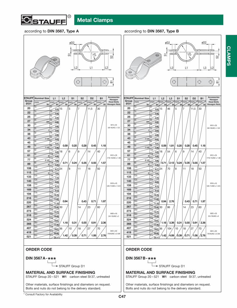
C47
Metal Clamps
according to DIN 3567, Type A according to DIN 3567, Type B
CLA
MP
S
DIN 3567B-***STAUFF Group D1
ORDER CODE
MATERIAL AND SURFACE FINISHINGSTAUFF Group 20 – 521 W1 carbon steel St 37, untreated
Other materials, surface finishings and diameters on request.Bolts and nuts do not belong to the delivery standard.
B1
L1
ø D 2
S1
D 1
L2 L3
S2
L2
ø D 2
DIN 3567A-***STAUFF Group D1
ORDER CODE
MATERIAL AND SURFACE FINISHINGSTAUFF Group 20 – 521 W1 carbon steel St 37, untreated
Other materials, surface finishings and diameters on request.Bolts and nuts do not belong to the delivery standard.
L1
ø D 2
S1
D 1
L2 L2
S2B1
STAUFFGroupØD1 in
Nominal Size
mm
20
L1
mmin
L2
mm
S1
mmin in
S2
mmin in
D2
mmin
B1
mm
AccessoriesHexagon
Head BoltsHexagon Nuts
22
25
27
30
34
38
43
45
49
57
61
77
89
108
115
133
140
159
169
194
216
220
267
273
318
324
368
407
419
521
15
15
20
20
25
25
32
32
40
40
50
50
65
80
100
100
125
125
150
150
175
200
200
250
250
300
300
350
400
400
500
1
1 1/4
1 1/2
2
2 1/2
3
4
57
59
62
663/4
68
72
76
82
84
88
104
108
122
136
172
178
196
204
222
232
280
284
342
348
392
398
444
498
510
614
2.24
2.32
2.44
2.60
2.68
2.83
2.99
3.23
3.31
3.46
4.09
4.25
4.80
5.35
6.77
7.01
7.72
8.03
8.74
9.13
10.16
11.02
11.18
13.46
13.70
15.43
15.67
17.48
19.61
20.08
24.17
258
0.59
15
0.20
5
0.28
7
0.45
11,5
1.18
30
0.71
18
0.24
6
0.35
9
0.55
14
1.57
40
0.94
24
0.43
8
0.71
11
1.97
18 50
0.311.18
30
0.55
14
0.91
23
2.36
60
1.42
36
0.39
10
0.71
18
1.06
27
2.76
70M24 x 60
7/8-9UNC x 2-3/8
M20 x 50
3/4-10UNC x 2
M16 x 45
5/8-11UNC x 1-3/4
M12 x 35
7/16-14UNC x 1.38
M10 x 30
3/8-16UNC x 1.25
STAUFFGroupØD1 in
Nominal Size
mm
20
L1mm
L2mm
in
AccessoriesHexagon
Head BoltsHexagon Nuts
22
25
27
30
34
38
43
45
49
57
61
77
89
108
115
133
140
159
169
194
216
220
267
273
318
324
368
407
419
521
15
15
20
20
25
25
32
32
40
40
50
50
65
80
100
100
125
125
150
150
175
200
200
250
250
300
300
350
400
400
500
1
1 1/4
1 1/2
2
2 1/2
3
4
57
59
62
663/4
68
72
76
82
84
88
104
108
122
136
172
178
196
204
222
232
280
284
342
348
392
398
444
498
510
614
2.24
2.32
2.44
2.60
2.68
2.83
2.99
3.23
3.31
3.46
4.09
4.25
4.80
5.35
6.77
7.01
7.72
8.03
8.74
9.13
10.16
11.02
11.18
13.46
13.70
15.43
15.67
17.48
19.61
20.08
24.17
258
M24 x 60
7/8-9UNC x 2-3/8
M20 x 50
3/4-10UNC x 2
M16 x 45
5/8-11UNC x 1-3/4
M12 x 35
7/16-14UNC x 1.38
M10 x 30
3/8-16UNC x 1.25
L3
inmm
in
S1mm
in
S2mm
in
D2 B1mm
inmm
in
0.59
15
0.20
5
0.28
7
0.45
11,5
1.18
30
0.71
18
0.24
6
0.35
9
0.55
14
1.57
40
0.94
24
0.43
8
0.71
11
1.97
18 50
0.311.18
30
0.55
14
0.91
23
2.36
60
1.42
36
0.39
10
0.71
18
1.06
27
2.76
70
46
1.81
2.13
54
70
2.76
86
3.39
104
4.09
* Consult Factory for Availability

STAUFFGroupØD1
L1 L2 L3 H D2 B S
mmin
mmin
mmin
mmin
mmin
mmin
mmin
Dia. Range
mmin
7
9
13
15,5
19
23
26
28,5
31
36
39
43
46
49
52*
58
61
28,5–31
5,5-7
7-9
9,5-13
13-15,5
15,5-19
20-23
26-28,5
23-26
33-36
36-39
39-43
43-46
46-49
49-52
53-58
58-61
0.22-0.28
0.28-0.35
0.37-0.51
0.51-0.61
0.61-0.75
0.79-0.91
0.91-1.02
1.02-1.12
1.12-1.22
1.30-1.42
1.42-1.54
1.54-1.69
1.69-1.81
1.81-1.93
1.93-2.05
2.09-2.28
2.28-2.40
22
27
40
41
43
51
52
53
57
59
68
70
73
76
78
80
0.87
1.06
1.57
1.61
1.69
2.01
2.05
2.17
2.24
2.32
2.68
2.76
2.87
2.99
3.07
3.15
14
18
25
26
28
35
36
37
41
43
48
50
53
56
58
60
0.55
0.71
0.98
1.02
1.10
1.38
1.42
1.54
1.61
1.69
1.89
1.97
2.09
2.20
2.28
2.36
672.64
27,51.08
33,51.32
49,51.95
522.05
55,52.19
702.76
732.87
75,52.97
813.19
83,53.29
94,53.72
983.86
105,54.15
1104.33
1154.53
118,54.67
6,6
0.43
1419
0.75
50.20
60.24
90.35
120.47
150.59
220.87
240.94
271.06
321.26
381.50
411.61
441.73
471.85
522.05
530
0.98
25
0.12
3
2
0.08
C48
Clamps - Heavy Saddles
according to DIN 1592 according to DIN 1593
CLA
MP
S
* similar to DIN 1592
DIN 1592-***STAUFFGroup Ø D1
ORDER CODE
MATERIAL AND SURFACE FINISHINGSTAUFF Group 7 – 49 W3 carbon steel St 37,
zinc plated (Fe/Zn 8 C)STAUFF Group 52 – 61 W1 carbon steel St 37, untreated
(Surface finishing on request only)
Other materials, surface finishings and diameters upon request.
DIN 1593-***STAUFFGroup Ø D1
ORDER CODE
MATERIAL AND SURFACE FINISHINGSTAUFF Group 7 – 77 W3 carbon steel St 37,
zinc plated (Fe/Zn 8 C)STAUFF Group 81 – 115 W1 carbon steel St 37, untreated
(Surface finishing on request only)
Other materials, surface finishings and diameters upon request.
L2
ø D 2
SH
ø D 1
L1
B
L1
ø D 2 S
H
ø D 1
L3
B
L2
55 392.09 1.46
160.63
200.790.26
11
0.5534
1.34
1.18
0.20
40
18
0.71572.24 1.57 0.31
8
STAUFFGroupØD1
L1 L2 H D2 B S
mmin
mmin
mmin
mmin
Dia. Range
mmin
7
9
13
15,5
19
23
26
28,5
31
36
39
43
46
49
58
61
71
77
28,5–31
5,5-7
7-9
9,5-13
13-15,5
15,5-19
20-23
26-28,5
23-26
33-36
36-39
39-43
43-46
46-49
53-58
58-61
67-71
73-77
0.22-0.28
0.28-0.35
0.37-0.51
0.51-0.61
0.61-0.75
0.79-0.91
0.91-1.02
1.02-1.12
1.12-1.22
1.30-1.42
1.42-1.54
1.54-1.69
1.69-1.81
1.81-1.93
2.09-2.28
2.28-2.40
2.64-2.80
2.87-3.03
44
48
52
56
60
82
84
90
106
110
120
122
142
152
1.73
1.89
2.05
2.20
2.36
3.23
3.31
3.54
4.17
4.33
4.72
4.80
5.59
6.93
28
32
36
40
44
56
58
64
80
84
88
90
120
1.10
1.26
1.42
1.57
1.73
2.20
2.28
2.52
3.15
3.31
3.46
4.33
5.35
6,6
0.2619
0.75
50.20
60.24
90.35
120.47
150.59
220.87
240.94
271.06
321.26
341.34
381.50
411.61
441.73
522.05
572.24
662.60
722.83
mmin
mmin
11
0.43
25
0.79
3
2
0.08
30
1.18
40
5
81
91
103
109
115
77-81
86-91
99-103
105-109
110-115
3.03-3.19
3.39-3.58
3.90-4.06
4.13-4.29
4.33-4.53
184
198
214
220
7.24
7.80
8.43
8.90
144
174
180
6.22
6.85
7.32
762.99
853.35
983.86
1044.09
1094.29
176
5.98
2268.66
110
136
158
1867.09
5.67
4.72
3.54
160.63
20
0.98 0.12
0.20
14
0.55
1.570.71 0.31
18
8
* Consult Factory for Availability

C49
Clamps - Light Saddles
according to DIN 1596 according to DIN 1597
CLA
MP
S
STAUFFGroupØD1
* similar to DIN 1596
DIN 1596 -***STAUFFGroup Ø D1
ORDER CODE
MATERIAL AND SURFACE FINISHINGSTAUFF Group 7 – 61 W3 carbon steel St 37,
zinc plated (Fe/Zn 8 C)
Other materials, surface finishings and diameters upon request.
DIN 1597-***STAUFFGroup Ø D1
ORDER CODE
MATERIAL AND SURFACE FINISHINGSTAUFF Group 7 – 61 W3 carbon steel St 37,
zinc plated (Fe/Zn 8 C)
Other materials, surface finishings and diameters upon request.
L2
ø D 2
SH
ø D 1
L1
B
L1
ø D 2 S
H
ø D 1
L3
B
L2
L1 L2 L3 H D2 B S
mmin
mmin
mmin
mmin
mmin
mmin
mmin
Dia. Range
mmin
7
9
13
15,5
19
23
26
28,5
31
33*
36
39
43
46
49
52*
58
61
28,5–31
5,5-7
7-9
9,5-13
13-15,5
15,5-19
20-23
26-28,5
23-26
31-33
33-36
36-39
39-43
43-46
46-49
49-52
53-58
58-61
0.22-0.28
0.28-0.35
0.37-0.51
0.51-0.61
0.61-0.75
0.79-0.91
0.91-1.02
1.02-1.12
1.12-1.22
1.22-1.30
1.30-1.42
1.42-1.54
1.54-1.69
1.69-1.81
1.81-1.93
1.93-2.05
2.09-2.28
2.28-2.40
26
28
30
32
34
43
44
47
56
57
59
61
62
67
72
74
77
1.02
1.10
1.18
1.26
1.34
1.69
1.73
1.85
2.20
2.24
2.32
2.40
2.44
2.64
2.83
2.91
3.03
14
16
18
20
22
28
29
32
36
40
42
44
45
48
53
55
58
0.55
0.63
0.71
0.79
0.87
1.10
1.14
1.26
1.42
1.57
1.65
1.73
1.77
1.89
2.09
2.17
2.28
57,52.26
31,51.24
34,51.36
38,51.52
41,751.64
45,51.79
602.36
64,252.53
65,52.58
75,52.97
783.07
81,53.21
85,53.37
883.46
95,53.76
1024.02
1074.21
111,54.39
6,6
0.26
9
0.35
11
0.43
14
0.55
190.75
50.20
60.24
90.35
120.47
150.59
220.87
240.94
271.06
291.14
321.26
341.34
381.50
411.61
441.73
471.85
522.05
562.24
40
1.57
4
0.31
30
1.18 0.20
325
0.98
16
0.63
0.79
20
0.12
2
2
0.08
STAUFFGroupØD1
* similar to DIN 1597
L1 L2 H D2 B S
mmin
mmin
mmin
mmin
Dia. Range
mmin
7
9
13
15,5
19
23
26
28,5
31
33*
36
39
43
46
49
52*
58
61
28,5–31
5,5-7
7-9
9,5-13
13-15,5
15,5-19
20-23
26-28,5
23-26
31-33
33-36
36-39
39-43
43-46
46-49
49-52
53-58
58-61
0.22-0.28
0.28-0.35
0.37-0.51
0.51-0.61
0.61-0.75
0.79-0.91
0.91-1.02
1.02-1.12
1.12-1.22
1.22-1.30
1.30-1.42
1.42-1.54
1.54-1.69
1.69-1.81
1.81-1.93
1.93-2.05
2.09-2.28
2.28-2.40
44
48
52
56
60
76
78
84
92
104
108
112
114
118
134
138
1.73
1.89
2.05
2.20
2.36
2.99
3.07
3.31
3.62
4.09
4.25
4.41
4.49
4.65
5.28
5.43
28
32
36
40
44
56
58
64
72
80
84
88
90
106
110
1.10
1.26
1.42
1.57
1.73
2.20
2.28
2.52
2.83
3.15
3.31
3.46
3.54
4.17
4.33
5,5
0.2219
0.75
50.20
60.24
90.35
120.47
150.59
220.87
240.94
271.06
291.14
321.26
341.34
381.50
411.61
441.73
471.85
522.05
562.24
mmin
mmin
6,6
0.26
20
0.79
16
0.63
2
0.08
1,5
0.06
9
0.35
11
0.43
25
0.98
30
1.18
3
0.12
* Consult Factory for Availability
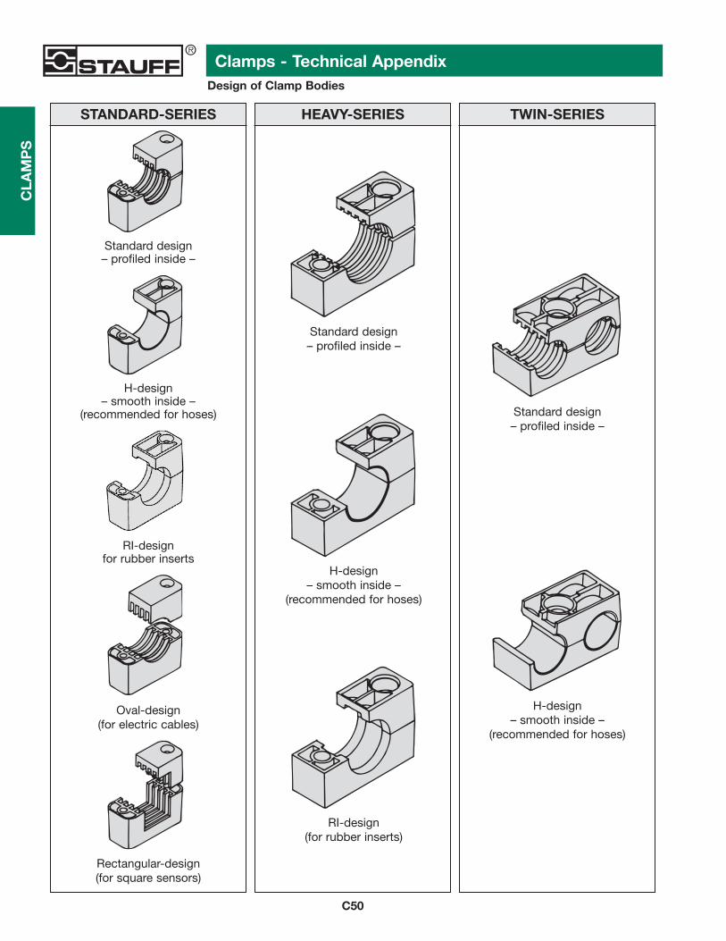
C50
Clamps - Technical AppendixDesign of Clamp Bodies
CLA
MP
S
STANDARD-SERIES HEAVY-SERIES TWIN-SERIES
Standard design – profiled inside –
H-design – smooth inside –
(recommended for hoses) Standard design– profiled inside –
Oval-design(for electric cables)
H-design– smooth inside –
(recommended for hoses)
Rectangular-design(for square sensors)
Standard design – profiled inside –
H-design – smooth inside –
(recommended for hoses)
RI-design(for rubber inserts)
RI-designfor rubber inserts

C51
Clamps - Technical AppendixInstallation Information
CLA
MP
S
INSTALLATION ONWELD PLATES
STAUFF weld plates are available for thefollowing Series:
– Standard-Series– Heavy-Series– Twin-Series– Special Clamps
For best alignment of STAUFF clamps it isrecommended to mark their location first.Weld plates into position, push on bottomhalf of clamp, install pipe, mount top halfof clamp and cover plate and bolt unittogether.In order to avoid damage to the clampbodies it is recommended to mount theplastic clamp bodies after having weldedthe weld plates into position.
INSTALLATION ONMOUNTING RAILS
STAUFF mounting rails can be used withthe following Series:
– Standard-Series– Heavy-Series (Group 3S – 6S)– Twin-Series– Special Clamps
STAUFF mounting rails are available infour different height sizes.The rails are either welded or bolted to thesupporting structure.For Standard- and Twin-Series inserthexagon rail nut and turn to lock.For Heavy-Series slide in rail nut.Push on bottom half of clamp, install pipe,mount top half of clamp, cover plate andbolt unit together.Clamp units can be adjusted before beingfirmly bolted.
MULTI-LEVEL ASSEMBLY
STAUFF multi-level pipe clamps permiteasy stacking of several tubes or pipes ofthe same group.(Twin-Clamps group 2 – 5 allow stackingof different group sizes.)The clamps are connected by stackingbolts (AF).Safety plates (SIG/SIP/SI) inserted betweenthe clamps prevent stacking bolts fromturning.STAUFF stacking assembly can be fittedto weld plates or to rails.

C52
Clamps - Technical AppendixMaterials, Material Properties and Technical Information
CLA
MP
S MATERIAL PP PA AL SAPOLYPROPYLENE
CopolymericPOLYAMIDE ALUMINIUM
AlSi12THERMOPLASTIC
ELASTOMER
MECHANICAL PROPERTIES
Tensile E-Module 1073 N/mm2 > 1400 N/mm2 > 65000 N/mm2 0,96 g/cm2(ISO 527) (ISO 527)
Notch Impact Strength 7,5 kJ/mm2 at 23°C > 15 kJ/m2 at 23°C - - - - - -(nach Charpy / ISO 179/1eA) (acc. to Charpy / ISO 179/1eA)
Low Temperature 3,1 kJ/mm2 at -30°C > 03 kJ/m2 at -30°C - - - - - -Notch Impact Strength (nach Charpy / ISO 179/1eA) (acc. to Charpy / ISO 179/1eA)
Tensile Strength at Yield 25 N/mm2 > 55 N/mm2 > 150 N/mm2 7,1 N/mm2(Tensile Strength) (ISO 527) (ISO 527) (DIN EN 10002) (ISO 37)
Ball Indentation Hardness 45,4 N/mm2 > 65 N/mm2 > 55 HBS - - -(Brinell Hardness) (ISO 2039-1) (ISO 2039-1)
Shore Hardness - - - - - - - - - 87A (ISO 868)
THERMAL PROPERTIES
Max Temperature -20° to + 215°F -40° to + 356°F -40° to + 752°F -40° to + 425°F (Brief Exposure) -30° to + 102°C -40° to + 180°C -40° to + 400°C -40° to + 210°C
CHEMICAL PROPERTIES
Weak Acids, Solvents conditionally conditionally conditionallyconsistent consistent consistent
consistent
Benzine, Mineral Oils conditionally conditionallyconsistent consistent
consistentconsistent
Alcohol, Other Oils, Seawater consistentconsistentconsistentconsistent
NOTES The stated information has been defined for conditions according to ISO 1110.
Tensile strengths, fatigue strength (under reversed bending stress) and impact bending toughness rise constantly at decreasing temperature level, the breaking elongation normallydecreases at a decreasing temperature level.
The above stated information is shown without any obligation and does not release you from owntest arrangements. Tightening Torques and Maximum Loads need to be considered (see page C54).
*1
*2
*1
*2
CLAMP BODIES
METAL PARTS
Unless otherwise stated, all metal parts are made of carbon steel St37, surface finishing according to order code.
Surface FinishingsIn addition to the standard surface finishings stated several alternative finishings are also available on request.
Stainless Steel Metal PartsAll metal parts are also available ex stock in two different stainless steel qualities:
Stainless Steel (W4) A2 - 1.4301/1.4305 (AISI 304)Stainless Steel (W5) A4 - 1.4401/1.4571 (AISI 316/316Ti)
ThreadsAll threaded parts are available with UNC and metric threads (see thread-chart on page C53).
COLOR GREEN BLACK NATURAL BLACK
Other materials (according to DIN5510, UL 94, NF F 16/101 forexample) are available on request.
Operating Temperature -22° to + 194°F -40° to + 284°F -40° to + 500°F -40° to + 248°F (Continuous Exposure) -30° to + 90°C -40° to + 140°C -40° to + 260°C -40° to + 120°C
*2

C53
Clamps - Technical Appendix
CLA
MP
S
Pipe-O.D. Distance A[mm] [inch] [m] [ft]
6.0 — 12.7 1.0
12.7 — 22.0 1.2
22.0 — 32.0 1.5
32.0 — 38.0 2.0
38.0 — 57.0 2.7
57.0 — 75.0 3.0
75.0 — 76.1 3.5
76.1 — 88.9 3.7
88.9 — 102.0 4.0
102.0 — 114.0 4.5
114.0 — 168.0 5.0
168.0 — 219.0 6.0
219.0 — 324.0 6.7
324.0 — 356.0 7.0
356.0 — 406.0 7.5
406.0 — 419.0 8.2
419.0 — 508.0 8.5
508.0 — 521.0 9.0
521.0 — 558.0 10.0
558.0 — 800.0 12.5
RECOMMENDED DISTANCE BETWEEN CLAMPS
BASIC MOUNTING INSTRUCTIONS
THREAD CHART
The recommended distances betweenclamps stated below are standard valuesand are valid for static loads.
Pipe bends should be supported by STAUFF clamps as near to the bends as possible.
Furthermore, it is recommended to design these clamps as fixed point clamps.
The first clamp should be placed directly behind the threaded connection or coupling. This protects the threaded connection or coupling from vibrations.
If valves are incorporated in the pipelines, it is recommended that support is provided in front of and behind these valves
Metric vs. UNC Thread
STAUFF Metric UNCGroup Thread Thread
TWIN-SERIES
1 D M 6 1/4 – 20 UNC
2 D
3 DM 8 5/16 – 18 UNC
4 D
5 D
STAUFF Metric UNCGroup Thread Thread
HEAVY-SERIES
3 S
4 S M 10 3/8 – 16 UNC
5 S
6 S M 12 7/16 – 14 UNC
7 S M 16 5/8 – 11 UNC
8 S M 20 3/4 – 10 UNC
9 S M 24 7/8 – 9 UNC
10 S M 30 1 1/8 – 7 UNC
11 SM 30 1 1/4 – 7 UNC
12 S
A
STAUFF Metric UNCGroup Thread Thread
STANDARD-SERIES
1
1A
2
3
4 M 6 1/4 – 20 UNC
5
6
7
8
.23" - .50" 3.3
.50" - .86" 4.0
.86" - 1.25" 5.0
1.25" - 1.50" 6.5
1.5" - 2.25" 8.8
2.25" - 2.95" 9.8
2.95" - 3.0" 11.5
3.0" - 3.50" 12.0
3.50" - 4.0" 13.0
4.0" - 4.50" 14.7
4.50" - 6.6" 16.5
6.6" - 8.6" 19.6
8.6" - 12.7" 22.0
12.7" - 14.00" 23.0
14.00" - 16.00" 24.6
16.00" - 16.50" 26.9
16.50" - 20.00" 27.9
20.00" - 20.50" 29.5
20.50" - 22.00" 32.8
22.00" - 31.50" 41.0

1 8 6 0,6 135 10 7 0,6 135 12 9 3,5 7871A 8 6 1,1 247 10 7 0,7 157 12 9 4,2 9442 8 6 1,3 292 10 7 0,8 180 12 9 4,3 9673 8 6 1,4 315 10 7 1,6 360 12 9 4,9 1.1014 8 6 1,5 337 10 7 1,7 382 12 9 5,0 1.1245 8 6 1,9 427 10 7 2,0 450 12 9 7,3 1.6416 8 6 2,0 450 10 7 2,5 562 12 9 8,9 2.0007 8 6 2,3 517 10 7 3,2 719 N/A N/A N/A N/A8 8 6 2,6 585 10 7 3,5 787 N/A N/A N/A N/A
C54
Clamps - Technical AppendixTightening Torques And Maximum Loads In Pipe Direction
CLA
MP
S
1D
2D
3D
4D
5D
03S
4S
05S
6S
07S
8S
09S
10S
11S
12S
TWIN-SERIES (according to DIN 3015, part 3)
STANDARD-SERIES (according to DIN 3015, part 1)
Polypropylene Polyamide Aluminum
STAUFF Hexagon Tightening Max. load in Tightening Max. load in Tightening Max. load inGroup Head Bolt torque pipe direction F torque pipe direction F torque pipe direction F
[Nm] Ft/lb [kN] lbf [Nm] Ft/lb [kN] lbf [Nm] Ft/lb [kN] lbf
All tightening torques and maximum loads in pipe direction refer to clamps withcover plates and hexagon head bolts acc. to DIN EN ISO 4014/4017 (DIN 931/933).
The max. load in pipe direction (according to DIN 3015, part 10) is an average value,determined by three tests at 23° C with a steel pipe according to DIN 2448, St 37 –rolled surface – taking static friction into consideration.
Sliding starts when the shown values (F) are reached.
HEAVY-SERIES (according to DIN 3015, part 2)
F
Polypropylene Polyamide Aluminum
STAUFF Hexagon Tightening Max. load in Tightening Max. load in Tightening Max. load inGroup Head Bolt torque pipe direction F torque pipe direction F torque pipe direction F
[Nm] Ft/lb [kN] lbf [Nm] Ft/lb [kN] lbf [Nm] Ft/lb [kN] lbf
Polypropylene Polyamide
STAUFF Hexagon Tightening Max. load in Tightening Max. load inGroup Head Bolt torque pipe direction F torque pipe direction F
[Nm] Ft/lb [kN] lbf [Nm] Ft/lb [kN] lbf
M6 / 1/4"-20UNC
M10 / 3/8" - 16UNC
M12 / 7/16" - 14UNC
M16 / 5/8" - 11UNC
M20 / 3/4" - 10UNC
M24 / 7/8" - 9UNC
M30 / 1 1/8" - 7UNC
M30 / 1 1/4" - 7UNC
M8 / 5/16" - 8UNC
M6 / 1/4" - 20UNC
12 9
12 9
15 11
30 22
45 33
80 59
110 81
133 132
148 147
199 200
1,6 360
2,9 652
3,3 742
8,2 1.843
11,0 2.472
14,0 3.147
28,0 6.300
40,0 8.992
119,0 26.752
168,0 37.767
20 15
20 15
25 18
40 30
55 41
150 111
200 148
350 258
370 273
450 332
4,2 944
4,5 1.044
5,1 1.146
9,3 2.090
25,8 5.800
21,0 4.720
32,0 7.193
48,0 10.790
125,0 27.650
180,0 40.465
30 22
30 22
35 26
55 41
120 86
220 162
250 184
500 369
500 369
600 443
12,1 2.720
15,1 3.395
15,5 3.485
29,5 6.609
34,9 7.845
70,6 15.871
50,0 11.240
84,5 18.996
181,5 40.802
244,5 54.965
05
12
12
12
08
4
9
9
9
6
0,9
2,1
1,9
2,7
1,7
05
12
12
12
08
4
9
9
9
6
0,9
2,1
1,9
2,7
1,7
0,9
2,2
2,0
2,9
2,5
202
472
427
607
382
202
495
450
652
562

At Stauff, we’re here to serve you.
We’re committed to providing the bestcustomer service in the industry.
Here are the e-mail links to key people anddepartments. Just click on the link to send ane-mail any time day or night.
Tell us what you need and we’ll respond.
You’ll get the answers you need from thepeople who know how to make it happen.
ADMINISTRATION/[email protected]
CUSTOMER SERVICE [email protected]
LITERATURE/MARKETING/TRADE SHOWS/PRODUCT INFORMATION [email protected]
ENGINEERING/PRODUCT SUPPORT Clamp [email protected]
Valves, Test, Accessories [email protected]
Filters, Filtration Accessories, [email protected]
COMPUTER OPERATIONS [email protected]
QUALITY [email protected]
For The Answers You Need, Contact Us …
Stauff CorporationPhone: 201-444-7800 www.stauffusa.com
Stauff Canada Ltd.Phone: 416-282-4608www.stauffcanada.com

Navigation Help
Toolbar Navigation
Next Page
Previous Page
First page
Last page
Go to Previous View
Go to Next View
Navigation Tool(for clicking on links or bookmarks)
Magnify(use to enlarge type or expand videoor graphics to full screen)
Show/Hide Navigation Pane
View Actual Size
View to Fit in Window
View to Fit Width
Tip: Always use the Previous View button to retrace your steps.
Use the Acrobat toolbarbuttons to quickly navigatethrough pages. The chartdescribes the basic functionof each button.
You may also use the book-mark navigation to the left.Just click on a bookmark toget the information desired.