Embed Size (px)
Citation preview

Pipe Standards
November 5, 2009

Agenda
• Purpose of revisions– 15 minutes
• Revisions overview– 20 minutes
• In depth explanation of Specifications and Standard Drawing revisions – 60 minutes
• Pay item examples– 20 minutes
• Critical inspection points– 5 minutes

PDH Credits
• PDH Credits: The Department does not report credits for classes that last less than ½ day. Professional Engineers and Land Surveyors can self report this Webinar. It will be 2 hours of structured time.
• All who signed in will receive a “Thank you for attending” email.

There was this

Then, there was this…

To drain the water, we needed some pipes…

Why are we here today?
• To improve pipe installation through a thorough understanding of the revised standards
• To reduce bumps in the road• Conducted pipe installation training two years
ago and we are not focusing on that today• New standards and specifications provide new
materials and details to improve performance of each pipe system
• Expand the use and understanding of alternate pipe materials

FHWA Guidanceconcerning alternate pipe materials
SAFETEA-LU
Pipe Selection Final Rule - Policy & Memos - Scour - Hydraulics - FHWA.mht
07-09-07 Memo Culvert Selection Procedures - Policy & Memos - Scour - Hydraulics - FHWA.mht
Section 5514 of the "Safe, Accountable, Flexible, Efficient Transportation Equity Act: A Legacy for Users," enacted August 10, 2005, requires the Secretary, within 180 days, to "... ensure that States provide for competition with respect to the specification of alternative types of culvert pipes through requirements that are commensurate with competition requirements for other construction materials, as determined by the Secretary.".
…policies that consider all available pipe products judged to be of satisfactory quality and equally acceptable on the basis of engineering and economic analyses. Given the differences in climate, environment and topography, we anticipate that there will be differences in culvert selection policies between various states.
With the potential for significant savings, the implementation schedule should not be based on protracted evaluation periods for experimental or pilot project installations
As previously noted, State DOTs should develop culvert selection policies that consider all available pipe products judged to be of satisfactory quality and equally acceptable on the basis of engineering and economic analyses


What
• 3 pages instead of 4 • Revised provisions• Flexible and rigid• Select material• Spring line• Fill height tables• Post inspection • Method B• Arch pipe and structural plate
pipe• Numbering scheme• Drainage Pipe special
provision

When
• New Standards and Project Special Provisions that accompany new Standards start with October 2009 letting– Section 300, – 3 standard drawings,– reinforced concrete pipe design >40’
• New special provision “Drainage Pipe” & Sec 310, Pipe Culverts starts with January 2010 letting
• Shown as special project detail in all plans until new standard book is issued

Summation
• New pipe standards designed to improve final product
• FHWA guidance requires competition through the use of alternate pipe materials
• Three new standard drawings• New standards

RevisionsAn Overview

3 pages
• 300D01 – Method of InstallationFlexible Pipe
• 300D02 – Method of InstallationRigid Pipe
• 300D03 – Method of InstallationFill Height Tables
Revisions

• Rigid PipeConcrete
Welded steel
Rigid and FlexibleRevisions

• Flexible Pipe (Except Structural Plate Pipe)Corrugated steel (no more BCCS),Corrugated aluminum, High density polyethylene (HDPE), Polyvinylchloride (PVC)
Rigid and FlexibleRevisions
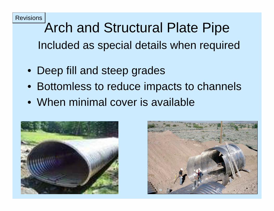
Arch and Structural Plate PipeIncluded as special details when required
• Deep fill and steep grades• Bottomless to reduce impacts to channels• When minimal cover is available
Revisions

Select Material
• Foundation Conditioning – Class V or Class VI• Pipe Bedding – Class III or Class II-Type 1
required for every pipe • Pipe Backfill - Class III or Class II-(Type 1 for
flexible, Type 1 or 2 for rigid) required for at least some portion of the backfill in every installation
• Amount and type of select backfill is dependent upon type of pipe and installation condition
Revisions

Select Material Class 2

Select Material Class 3
Select MaterialFoundation Conditioning
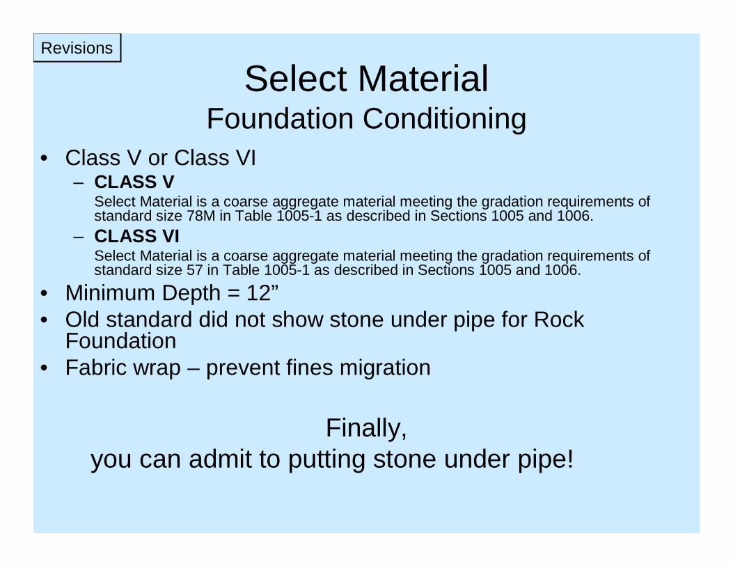
• Class V or Class VI– CLASS V
Select Material is a coarse aggregate material meeting the gradation requirements of standard size 78M in Table 1005-1 as described in Sections 1005 and 1006.
– CLASS VISelect Material is a coarse aggregate material meeting the gradation requirements of standard size 57 in Table 1005-1 as described in Sections 1005 and 1006.
• Minimum Depth = 12”• Old standard did not show stone under pipe for Rock
Foundation• Fabric wrap – prevent fines migration
Finally, you can admit to putting stone under pipe!
Revisions

Select MaterialBedding
• Pipe Bedding – Class III or Class II Type 1 used under every installation. 6” min.
CLASS III (Sec. 1016)Type 1 - Select Material is a natural or manufactured fine aggregate material meeting the gradation requirements of standard size 2S or 2MS in Table 1005-2 as described in Sections 1005 and 1006.Type 2 - Select Material is a granular soil material meeting the requirements of AASHTO M145 for soil classification A-1 or A-3.
CLASS IIType 1 - Select Material is a fine aggregate material consisting of crushed stone screenings (washed or unwashed) meeting the following gradationType 2 – Select Material is a granular soil material meeting the requirements of AASHTO M145 for soil classification A-2-4 with a maximum PI of 6 and A-4 soil containing 45% maximum passing a No. 200 sieve and a maximum PI of 6
• Sampling?– How to ensure proper material is used (sample it unless it has already been
sampled and passed for what you plan to use it for)The proper material is critical as fill height tables are based on installation and materials used. Tables based on an analysis LRFD and AASHTO and ASTM by our Structure Design Unit and Geotechnical Unit. Proper backfill was a part of the design process and is critical in providing support to the pipe systems.
Revisions

Summary
• Three new standard drawings– Effective with October 2009 letting
• Select material– Foundation Conditioning – Bedding

Trench WidthPipe in Trench
• From 2006 standard OD + 4ft to:• New standard OD + 3ft• Why?
– More closely matches industry standard– Select material is easier to compact– Reduce amount of select material
Revisions

Haunch Area
• Area adjacent to pipe that requires full compaction prior to further backfill
• Shown as a different symbol to draw attention to compaction; however, it is the same select material
• Remember, the area under the pipe is compacted by the pipe, the bedding is compacted with equipment then the haunch is full compacted prior to further fill.
Revisions

Fill Height Tables
• Added to Standard Drawings so that field forces can cross reference the pipe type shown in the plans and drainage summary against the field fill height
• Based off finished subgrade elevation, not finished grade, not stone
Revisions
• No Method B• Added Class II RCP• Changed fill heights when compared to
previous table.
Fill Height Table Changes
Revisions

Revisions
100’(CS60’ (Al)
36’(CS)22’(Al)
12”13”24” Corr.Metal
30’20’24”12”24” PVC
20’20’24”12”24” HDPE
20’23’24”15”24” RCP Cl. III
NewMax
Old MaxNew MinOld MinPipe
Changed fill heights when compared to previous table .

• No Method B• Added Class II RCP• Changed fill heights when compared to
previous table. • If the fill height (cover) is less than 2’, then
Class IV RCP or Class V RCP is required.
Fill Height Table Changes
Revisions

The differences in RCP classes are…Revisions
$34.76$32.19$25.75$25.75RCP30"
$19.04$17.63$14.10$14.10RCP24"
$14.38$13.31$10.65$10.65RCP18"
$11.48$10.63$8.50$8.50RCP15"
VIVIIIIIClass
“D” load strength of pipe
Class II: 1,000 lb/ft/ftClass III: 1,350 lb/ft/ft Class IV: 2,000 lb/ft/ft Class V: 3,000 lb/ft/ft
Class of Concrete andAmount of Steel
When moving from Cl. II to Cl. V, reinforcing steel amount nearly doubles for each class increase.Concrete class stays 4000 psi but increases to 6000 psi for Cl. V
Typical Costs for various classes.

• No Method B• Added Class II RCP• Changed fill heights when compared to
previous table. • If the fill height (cover) is less than 2’, then
Class IV RCP or Class V RCP is required• The differences in RCP classes are:• 1’ minimum cover for side drain
Fill Height Table Changes
Revisions

Summary
• Trench widths• Haunch• Spring line• Fill height tables

Standard Drawings

Standard Drawings
Flexible Pipe Standard Drawing Details

Standard Drawings
Flexible Pipe What’s the same for all foundation conditions?
Loosely placed select material Cl. III or Cl. II-Type 1Leave uncompacted directly below the pipe.(ID/6 but not less than 6”)
Spring line = middle of pipeRun a density here

Standard Drawings
Flexible Pipe What’s the same for all foundation conditions?
Compact the haunch area
Select material Cl. III or Cl. II-Type 1above and below springline(1’ above top of pipe)
Undercut depth = “As Directed”
OD x 3

Standard Drawings Flexible Pipe Find the detail differences between the foundation conditions
Use Select Type V or VI for Foundation conditioningEncapsulate with fabric (the line is light on the bottom
but a full wrap of fabric is required)½” per foot of fill above the pipe(Not less than 12” nor more than 24”)
O.D. + 2’
O.D. + 3’
O.D. x 3 min
O.D. x 3 minThe top is OD X 3But the bottom isOD + 2 except “unsuitable above ground”

SimilarFill height measured to subgradeHDPE & PVC min. fill = 2’Corr. Metal min. fill = 1’
DifferencesHDPE max fill = 17’/20’PVC max fill = 30’More fill can be placed over Corr. Steel than over Corr. Al.
Side drain cover = 1’ min
Standard Drawings
The Engineer should determine when a fill height change requires a pipe typechange.
Flexible Pipe Fill Height Table

SummaryFlexible Pipe
• Foundation conditioning depth and type • Bedding material type and depth• Haunch• Fill height

Rigid PipeStandard Drawing Details
Standard Drawings

Rigid PipeWhat’s similar for all foundation conditions?
Standard Drawings
Loosely placed select material Cl. III or Cl. II-Type 1Leave uncompacted directly below the pipe.(ID/6 but not less than 6”)
Springline = middle of pipeRun a density here
Select material Cl. 3 or Cl. 2 between bedding & springline
O.D. x 3 min Select material Cl. 3 or Cl. 2-Type 1 for bedding

Rigid PipeWhat’s similar for all foundation conditions?
Standard Drawings
Compact the haunch area
Approved local materialabove the springline. Localmaterial = unclassified orborrow (how about comp. grading?)
Undercut depth =As Directed

Rigid PipeFind the differences
Standard Drawings
O.D. + 2’O.D. + 3’
Use Select Class V or VI for Foundation conditioningEncapsulate with fabric (the line is light on the bottom
but a full wrap of fabric is required½” per foot of fill above the pipe(Not less than 12” nor more than 24”)
O.D. x 3

If fill height exceeds 40’, LRFD design is requiredMinimum fill
Cl. III = 2’Cl. IV & V = 1’
Maximum fillCl. II = 10’Cl. III = 20’Cl. IV = 30’Cl. V = 40’
Side drain cover = 1’ min
Rigid PipeFill Height Tables
The Engineer should determine when a fill height change requires a pipe typechange.

Fill heights > 40’REINFORCED CONCRETE PIPE DESIGN (5-27-09)
1.0 GENERAL
This Special Provision covers the design and manufacture of reinforced concrete pipes which require fills greater than 40’ and less than or equal to 80’.
When the design of a reinforced concrete pipe is required in the contract plans, design the reinforced concrete pipe in accordance with the current edition of the AASHTO LRFD Bridge Design Specifications. Provide the diameter of pipe as indicated on the plans and manufacture the pipe in accordance with ASTM C 1417. Provide a reinforced concrete pipe that meets the requirements of Section 1032-9, Section 1077 and any other applicable parts of the Standard Specifications.
The design of the reinforced concrete pipe is the responsibility of the Contractor and is subject to review, comments and approval. Submit two sets of detailed plans for review. Include all details in the plans, including the size and spacing of the required reinforcement necessary to fabricate the reinforced concrete pipe. Include checked design calculations for the reinforced concrete pipe. Have a North Carolina Registered Professional Engineer seal the plans and design calculations. After the plans are reviewed and, if necessary, the corrections made, submit one set of reproducible tracings on 22" x 34" sheets to become part of the contract plans.
2.0 REINFORCED CONCRETE PIPE SECTIONS
A. Class
Reinforced concrete pipe sections manufactured in accordance with this Special Provision are designated by inside pipe diameter and design earth cover.
B. Design Criteria
The design of the reinforced concrete pipe shall be in accordance with Article 12.10.4.2 “Direct Design Method” of the current edition of the AASHTO LRFD Bridge Design Specifications. The following assumptions shall be used in the design calculations:
NCDOT Criteria for Direct Design Method
Process and Material Factors, Radial Tension, Frp=1.0 Shear Strength, Fvp=1.0 Design Concrete Strength - f’c 5,000 psi < f’c < 7,000 psi Heger Pressure Distribution - Type 2 Installation Vertical Arching Factor = 1.40 Horizontal Arching Factor = 0.40 Soil Unit Weight = 120 lb/ft3 Depth of Fluid = Inside Pipe Diameter Minimum Concrete Cover = 1.00” Crack Control = 0.90 (maximum)
Send to:Contract Standards and DevelopmentJoel Howerton -
Standards Engineer
Tech needs a copy of approved submittal to inspect.
SummaryRigid Pipe
• Foundation conditioning material and depth
• Bedding type and depth• Fill above springline• Fill height• Reinforced Concrete Pipe Design
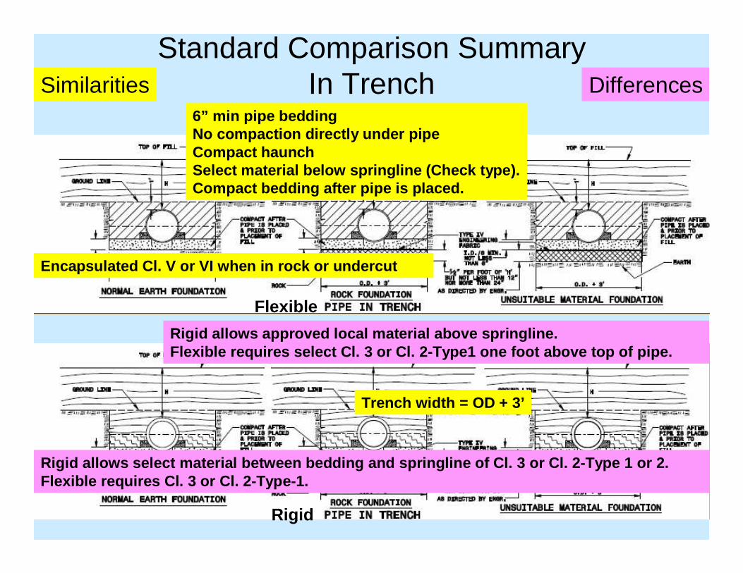
Standard Comparison SummaryIn Trench
Flexible
Rigid
6” min pipe beddingNo compaction directly under pipeCompact haunchSelect material below springline (Check type).Compact bedding after pipe is placed.
Trench width = OD + 3’
Encapsulated Cl. V or VI when in rock or undercut
Rigid allows approved local material above springli ne.Flexible requires select Cl. 3 or Cl. 2-Type1 one f oot above top of pipe.
Rigid allows select material between bedding and sp ringline of Cl. 3 or Cl. 2-Type 1 or 2.Flexible requires Cl. 3 or Cl. 2-Type-1.
Similarities Differences

Standard Comparison SummaryAbove Ground
Flexible
Rigid
6” min pipe beddingNo compaction directly under pipeCompact haunchSelect material below springline (Check type)Compact bedding after pipe is placedWidth of select is OD x 3
Encapsulated Cl. V or VI when in rock or undercut
Rigid allows approved local material above springli ne.Flexible requires select Cl. 3 or Cl. 2-Type1 one f oot above top of pipe.
Rigid allows select material between bedding to spr ingline of Cl. 3 or Cl. 2-Type 1 or 2.Flexible requires Cl 3 or Cl 2-Type-1.
Similarities Differences
Flexible and Rigid require a bedding width of OD + 2; however, both also require a bedding width of OD x 3 for unsuitable foundations.
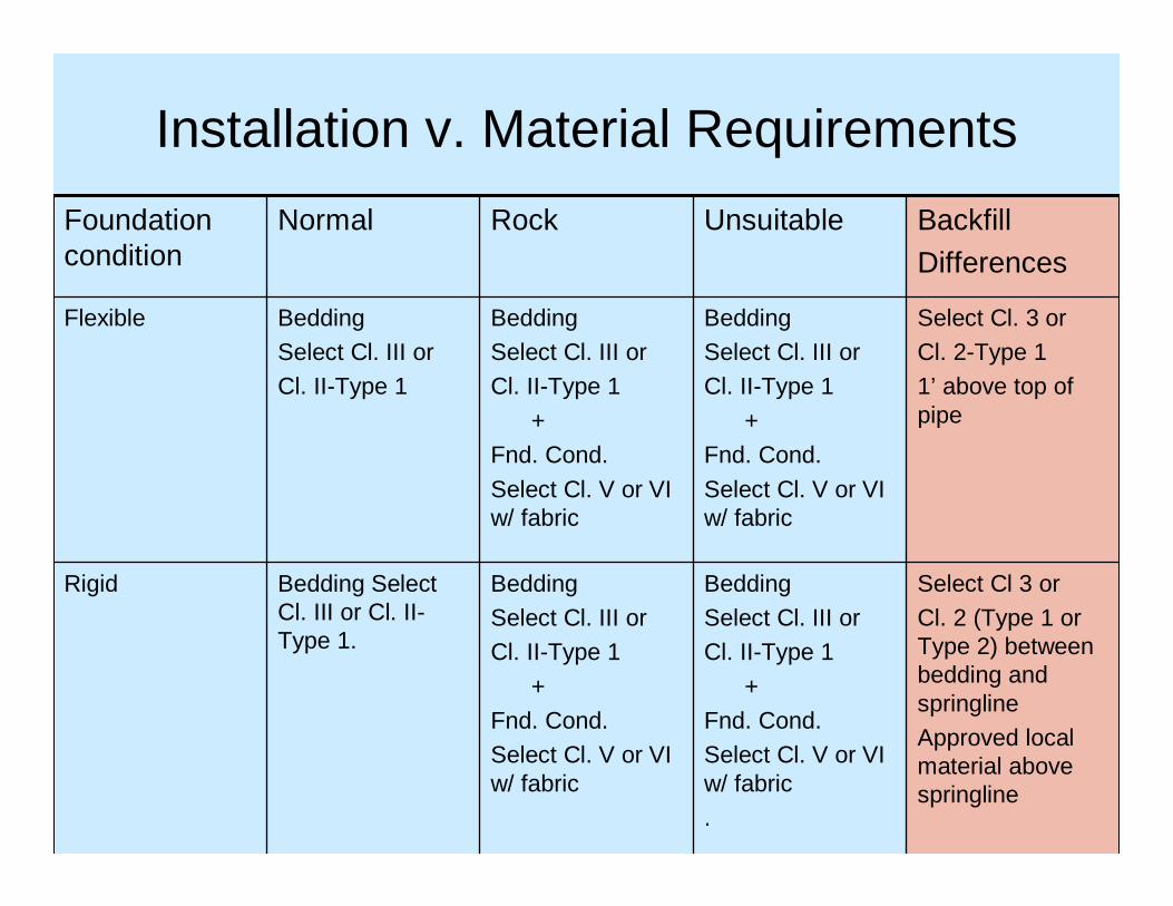
Installation v. Material Requirements
Select Cl 3 or Cl. 2 (Type 1 or Type 2) between bedding and springlineApproved local material above springline
BeddingSelect Cl. III or Cl. II-Type 1
+Fnd. Cond.Select Cl. V or VI w/ fabric.
BeddingSelect Cl. III or Cl. II-Type 1
+Fnd. Cond.Select Cl. V or VI w/ fabric
Bedding Select Cl. III or Cl. II-Type 1.
Rigid
Select Cl. 3 orCl. 2-Type 1 1’ above top of pipe
BeddingSelect Cl. III or Cl. II-Type 1
+Fnd. Cond.
Select Cl. V or VI w/ fabric
BeddingSelect Cl. III or Cl. II-Type 1
+Fnd. Cond.
Select Cl. V or VI w/ fabric
BeddingSelect Cl. III or Cl. II-Type 1
Flexible
Backfill
Differences
UnsuitableRockNormalFoundation condition
Provisions

Since June 2006, we used it.
Had restrictions that limited it to drives and outside ditches
In Jan 2010, Drainage Pipe special provision that will expand the use of alternates.
Side drain provision and drainage pipe provision will replace alt pipe provision.
History of ProvisionsHistory
PIPE ALTERNATES: (7-18-06) (Rev 4-17-07) SP3 R36
Description The Contractor may substitute Aluminized Corrugated Steel Pipe, Type IR or HDPE Pipe, Type S or Type D up to 48 inches in diameter in lieu of concrete pipe in accordance with the following requirements. Material Item Section HDPE Pipe, Type S or D 1032-10 Aluminized Corrugated Steel Pipe, Type IR 1032-3(A)(7) Aluminized Corrugated Steel Pipe will not be permitted in counties listed in Article 310-2 of the 2006 Standard Specifications. Construction Methods Aluminized Corrugated Steel Pipe Culverts and HDPE Pipe Culverts shall be installed in accordance with the requirements of Section 300 of the 2006 Standard Specifications for Method A, except that the minimum cover shall be at least 12 inches. Aluminized Corrugated Steel Pipe Culvert and HDPE Pipe Culvert will not be permitted for use under travelways, including curb and gutter. Measurement and Payment ____ "Aluminized Corrugated Steel Pipe Culvert to be paid for will be the actual number of linear feet installed and accepted. Measurement will be in accordance with Section 310-6 of the 2006 Standard Specifications. _____ "HDPE Pipe Culvert to be paid for will be the actual number of linear feet installed and accepted. Measurement will be in accordance with Section 310-6 of the 2006 Standard Specifications. Payment will be made under: Pay Item Pay Unit ___" Aluminized Corrugated Steel Pipe Culverts, ___" Thick Linear Foot ___" HDPE Pipe Culverts Linear Foot

• Previously, there were two pay items that allow choices for alternate bid items in the back of the contract.
• Now, Contractors can pick, within parameters, when they want to.
• New item Drainage Pipe Provision will be on regional and subregionaltier and allow choices of pipe types for cross lines and curb and gutter where they previously were not allowed. The tier type will be shown on title sheet of plans.
History
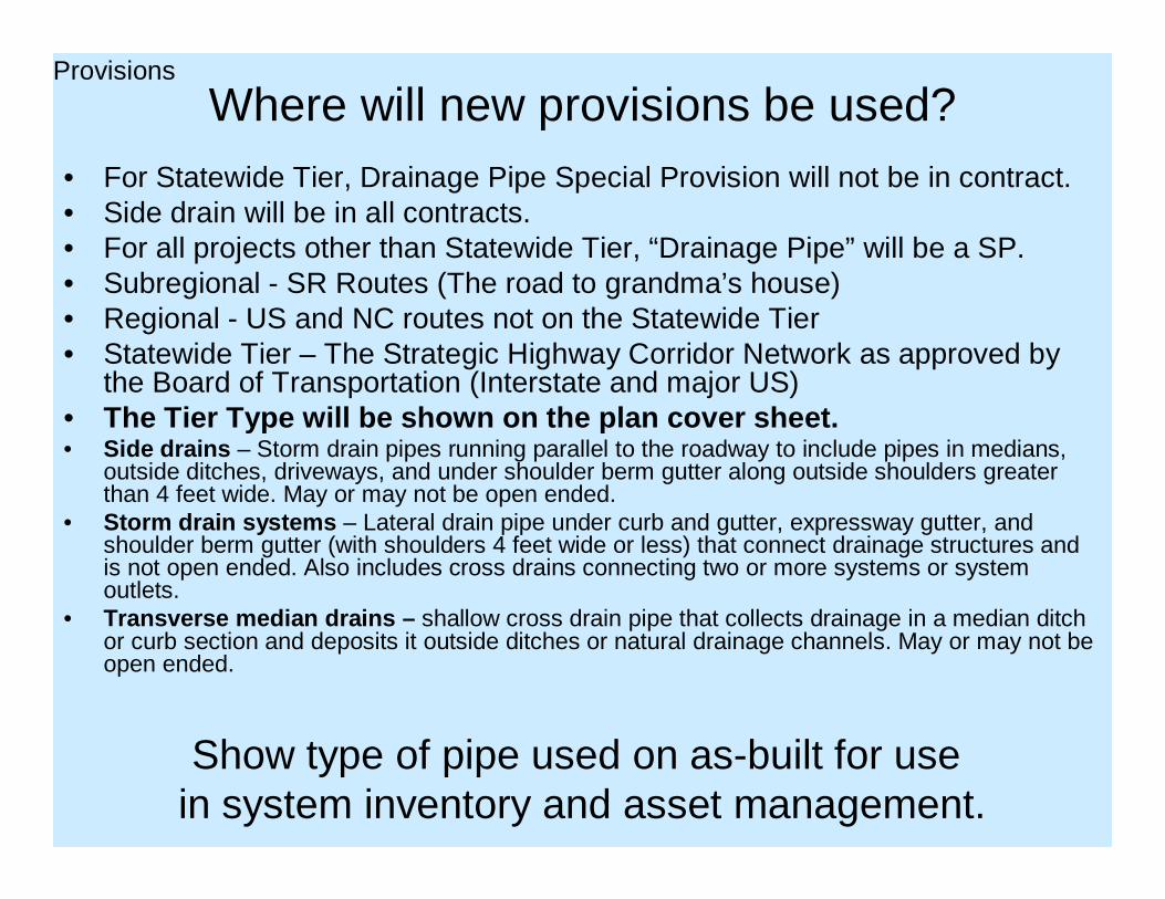
Where will new provisions be used?• For Statewide Tier, Drainage Pipe Special Provision will not be in contract.• Side drain will be in all contracts.• For all projects other than Statewide Tier, “Drainage Pipe” will be a SP. • Subregional - SR Routes (The road to grandma’s house)• Regional - US and NC routes not on the Statewide Tier • Statewide Tier – The Strategic Highway Corridor Network as approved by
the Board of Transportation (Interstate and major US)• The Tier Type will be shown on the plan cover sheet .• Side drains – Storm drain pipes running parallel to the roadway to include pipes in medians,
outside ditches, driveways, and under shoulder berm gutter along outside shoulders greater than 4 feet wide. May or may not be open ended.
• Storm drain systems – Lateral drain pipe under curb and gutter, expressway gutter, and shoulder berm gutter (with shoulders 4 feet wide or less) that connect drainage structures and is not open ended. Also includes cross drains connecting two or more systems or system outlets.
• Transverse median drains – shallow cross drain pipe that collects drainage in a median ditch or curb section and deposits it outside ditches or natural drainage channels. May or may not be open ended.
Show type of pipe used on as-built for usein system inventory and asset management.
Provisions

Key Changes
Show type of pipe used on as built for usein system inventory and asset management.
• No more unreinforced concrete pipe. Now Cl. II RCP• Side drain in both Statewide and Regional/Subregional
Tier• Only smooth inside wall pipe is allowed in Storm Drain
Systems.• Exceptions will be noted in Remarks column of Drainage
Summary.• Drainage pipe pay items will be shown as SP.
Provisions

COMPUTED BY: DATE: SHEET NO.
CHECKED BY: DATE:
RD
24
454
2
ABBREVI ATI ONS
S IZE
THICKNESS
OR GAUGE
E F G
SHEET TOTALS
CLASS III R.C. PIPE
DIVISION OF HIGHWAYS
TO
P E
LE
VA
TIO
N
INV
ER
T E
LE
VA
TIO
N
INV
ER
T E
LE
VA
TIO
N
A
M.H
. S
TD
. 840
.51
OR
84
0.53
M.H
. F
RA
ME
AN
D C
OV
ER
ST
D. 8
40.5
4
12'' 24''15'' 42'' 48' '
CO
RR
. S
TE
EL
EL
BO
WS
NO
. & S
IZE
C.B.
N.D.I.
D.I.
G.D.I.
G.D.I.(N.S .)
J.B.
M.H.
T.B.D.I .
T.B.J.B.
CATCH BASIN
NARROW DROP INLET
DROP INLET
GRATED DROP INLET
GRATED DROP INLET
(NARROW SLOT)
JUNCTION BOX
MANHOLE
TRAFFIC BEARING
DROP INLET
TRAFFIC BEARING
JUNCTION BOX
REMARKSCO
NC
. &
BR
ICK
PIP
E P
LU
G, C
.Y.
ST
D. 8
40.7
1
PIP
E R
EM
OV
AL
LIN
. F
T.
CO
NC
. C
OL
LA
RS
CL
. "B
" C
.Y. S
TD
. 84
0.7
2
.06
4
.06
4
.07
9
QU
AN
TIT
IES
FO
R D
RA
INA
GE
ST
RU
CT
UR
ES
*TO
TA
L L
.F. F
OR
PA
Y
QU
AN
TIT
Y S
HA
LL
BE
CO
L.
'A'
+ (1
.3 X
CO
L.'
B')
10.
0' A
ND
AB
OV
E
C.S
.P.
STD. 838.01
OR
STD. 838.11
(UNLESS
NOTED
OTHERWISE)
BCU. YARDS
5.0
' TH
RU
10.
0'
STATI ON
ST
RU
CT
UR
E N
O.
FR
OM
TO
18''
DRAINAGE PIPE
(RCP, CSP, CAAP,HDPE,or PVC)
LO
CA
TIO
N (
LT
, RT
, OR
CL
)'
SL
OP
E C
RIT
ICA
L
30'' 36''
.10
9
G.D
.I. F
RA
ME
WIT
H G
RA
TE
ST
D.
840
.20
G.D
.I. F
RA
ME
WIT
H T
WO
GR
AT
ES
ST
D.
840.
22
C.B
. S
TD
. 840
.01
OR
ST
D. 8
40.0
2
.10
9
TYPE OF
GRATE
G.D
.I. (
N.S
.) F
RA
ME
WIT
H G
RA
TE
ST
D.
840
.24
G.D
.I. (
N.S
.) F
RA
ME
WIT
H T
WO
GR
AT
ES
ST
D.
840
.24
J.B
. S
TD
. 840
.31
OR
840
.32
MA
NH
OL
E S
TD
. 840
.51
G.D
.I. T
YP
E "
A"
ST
D. 8
40.
17
OR
840
.26
G.D
.I. T
YP
E "
B"
ST
D. 8
40.
18
OR
840
.27
G.D
.I. T
YP
E "
D"
ST
D. 8
40.
19
OR
840
.28
15
inch
SID
E D
RA
IN P
IPE
18
inch
SID
E D
RA
IN P
IPE
24
inch
SID
E D
RA
IN P
IPE
LIN.
FT.
PE
R E
AC
H (
0' T
HR
U 5
.0')
ENDWALLS
R.C
.P.
42''
D.I.
ST
D. 8
40.
14
OR
ST
D. 8
40.1
5
D.I.
FR
AM
E A
ND
GR
AT
E S
TD
. 84
0.16
FRAME,
GRATES,
AND HOOD
STANDARD
840.03
48''
C.S . PIPE
(UNLESS NOTED OTHERWISE)
12''.0
64
.07
9
.06
4
15'' 18'' 24'' 30'' 36''
PROJECT NO.
12' ' 15'' 18'' 24'' 30''
CO
NC
RE
TE T
RA
NS
ITIO
NA
L
SE
CTI
ON
DR
OP
INL
ET
CA
TC
H B
AS
IN
CLASS III R.C. PI PE
(UNLESS NOTED OTHERWISE)
36'' 42'' 48''
Print Full SizePrint Half Size
Choose Project Tier
Drainage pipe could beRCP, HDPE,PVC,CSPCAAP unless Remarks list exclusions.
Regional/SubregionalTier
Example of when a type may be excluded:Where pipe connects a storm drain system.So from DI to DI in shoulder berm gutter wouldnot allow pipe with corrugations inside but from DI to DI in the median does allow corrugations inside pipe.Why: corrugations interfere with capacity calc.
Example: RCP is excludedwhere grade >10% such asoutlets from SBG.
Will there be side drain pipeand Drainage Pipe in the samecontract?If YES, why?
Side drain pipeFill < 10’Not in commercial driveNot if future widening planned
Provisions
.
If fill height is > 20’ or < 2’ then type of pipe willbe specified.
Counties:310-2 - No CorrugatedSteel in 24 coastal counties

COMPUTED BY: DATE: SHEET NO.
CHECKED BY: DATE:
RD
244
542
ABBREVIATIONS
SIZE
THICKNESS
OR GAUGE
E F G
SHEET TOTALS
CLASS III R.C. PIPE
DIVISION OF HIGHWAYS
TO
P E
LE
VA
TIO
N
INV
ER
T E
LE
VA
TIO
N
INV
ER
T E
LE
VA
TIO
N
A
M.H
. ST
D. 8
40.5
1 O
R 8
40.5
3
M.H
. FR
AM
E A
ND
CO
VE
R S
TD
. 84
0.5
4
12'' 24' '15'' 42' ' 48''
CO
RR
. ST
EE
L E
LB
OW
S N
O. &
SIZ
E
C.B.
N.D.I.
D.I .
G.D.I.
G.D.I.(N.S .)
J.B.
M.H.
T.B.D.I.
T.B.J.B.
CATCH BASIN
NARROW DROP INLET
DROP I NLET
GRATED DROP I NLET
GRATED DROP I NLET
(NARROW SLOT)
JUNCTI ON BOX
MANHOLE
TRAFFI C BEARING
DROP I NLET
TRAFFI C BEARING
JUNCTI ON BOX
REMARKSCO
NC
. & B
RIC
K P
IPE
PL
UG
, C.Y
. S
TD
. 840
.71
PIP
E R
EM
OV
AL
LIN
. F
T.
CO
NC
. CO
LL
AR
S C
L. "
B"
C.Y
. S
TD
. 84
0.7
2
.064
.064
.079
QU
AN
TIT
IES
FO
R D
RA
INA
GE
ST
RU
CT
UR
ES
*TO
TA
L L
.F.
FO
R P
AY
QU
AN
TIT
Y S
HA
LL
BE
CO
L.
'A'
+ (1
.3 X
CO
L.'B
')10
.0' A
ND
AB
OV
E
C.S
.P.
STD. 838.01
OR
STD. 838.11
(UNLESS
NOTED
OTHERWI SE)
BCU. YARDS
5.0
' TH
RU
10.
0'
STATION
ST
RU
CT
UR
E N
O.
FR
OM
TO
18''
CLASS II I R.C. PIPE
(UNLESS NOTED OTHERWI SE)
LO
CA
TIO
N (
LT
, RT
, OR
CL
)'
SL
OP
E C
RIT
ICA
L
30'' 36''
.109
G.D
.I. F
RA
ME
WIT
H G
RA
TE
ST
D.
840
.20
G.D
.I. F
RA
ME
WIT
H T
WO
GR
AT
ES
ST
D.
840.
22
C.B
. ST
D. 8
40.
01
OR
ST
D. 8
40.0
2
.109
TYPE OF
GRATE
G.D
.I. (
N.S
.) F
RA
ME
WIT
H G
RA
TE
ST
D.
840
.24
G.D
.I. (
N.S
.) F
RA
ME
WIT
H T
WO
GR
AT
ES
ST
D.
840.
24
J.B
. ST
D. 8
40.
31
OR
840
.32
MA
NH
OL
E S
TD
. 840
.51
G.D
.I. T
YP
E "
A"
ST
D.
840.
17 O
R 8
40.2
6
G.D
.I. T
YP
E "
B"
ST
D.
840.
18 O
R 8
40.2
7
G.D
.I. T
YP
E "
D"
ST
D.
840.
19 O
R 8
40.2
8
L IN.
FT.
PE
R E
AC
H (
0' T
HR
U 5
.0')
ENDWALLS
R.C
.P.
42''
D.I
. ST
D.
840.
14 O
R S
TD
. 84
0.1
5
D.I
. FR
AM
E A
ND
GR
AT
E S
TD
. 84
0.1
6
FRAME,
GRATES,
AND HOOD
STANDARD
840.03
48''
C.S. PIPE
(UNLESS NOTED OTHERWISE)
12''
.064
.079
.064
15' ' 18'' 24' ' 30'' 36''
PROJECT NO.
12'' 15'' 18'' 24'' 30''
CO
NC
RE
TE
TR
AN
SIT
ION
AL
SE
CTI
ON
DR
OP
INL
ET
CA
TC
H B
AS
IN
S IDE DRAIN PIPE
(RCP, CSP, CAAP,HDPE,or PVC)
36'' 42'' 48''
Print Full SizePrint Half Size
Choose Project Tier
Remarks may listexclusions or requirements
Drainage pipe specification will not appear on Statewide Tier
Statewide tier
Side drain pipeFill < 10’Not in commercial driveNot if future widening planned
Provisions
Counties:310-2 - No CorrugatedSteel in 24 coastal counties

Summary New Provisions Application
• Tiers• Drainage pipe on Statewide Tier only• Side Drain may be on all tiers• Exceptions noted in remarks of drainage
summary

Drainage Pipe - Special ProvisionDRAINAGE PIPE: (7-18-06) (Rev 7-17-09) SP3 R___ Description Where shown in the plans the Contractor may use Reinforced Concrete Pipe, Aluminum Alloy Pipe, Aluminized Corrugated Steel Pipe, HDPE Pipe, or PVC pipe in accordance with the following requirements. Material Item Section Corrugated Aluminum Alloy Pipe 1032-2(A) Aluminized Corrugated Steel Pipe 1032-3(A)(7) Corrugated Polyethylene Pipe (HDPE) 1032-10 Reinforced Concrete Pipe – Class II or III 1032-9(C) Polyvinyl-Chloride (PVC) 1032-11 Corrugated Steel Pipe will not be permitted in counties listed in Article 310-2 of the 2006 Standard Specifications. Only pipe with smooth inside walls will be allowed for storm drain systems. Storm drain systems are defined as pipe under curb and gutter, expressway gutter, and shoulder berm gutter that connects drainage structures and is not open ended. Construction Methods Pipe Culverts shall be installed in accordance with the contract documents. Where allowed by the plans, use any of the several alternate pipes shown herein, but only one type of pipe will be permitted between drainage structures or for the entire length of a cross line pipe. Measurement and Payment Measurement will be in accordance with Section 310-6 of the 2006 Standard Specifications. ___" Drainage Pipe will be paid for as the actual number of linear feet installed and accepted. Payment will be made under: Pay Item Pay Unit ___" Drainage Pipe Linear Foot
Jan. 2010 let
Provisions

Provision Revisions
• 300-2: Bedding material and foundation conditioning material
• 300-4: Class V or VI select encapsulated with fabric• 300-6: RCP Pipe > 42” use fabric that extends 12” on both sides of joint• 300-7: Loosely place bedding material, in a uniform layer, a depth equal to the inside
diameter of the pipe divided by 6 or 6 inches, whichever is greater. Leave bedding material directly beneath the pipe uncompacted and allow pipe seating and backfill to accomplish compaction. Excavate recesses to receive the bells where bells and spigot type pipe is used. Excavatable flowable fill may be used for backfill when approved by the Engineer. When using excavatable flowable fill, ensure that the pipe is not displaced and does not float during backfill. Submit methods for supporting the pipe and material placement to the engineer for review and approval.
• 300-8: Prior to final acceptance, the Engineer will perform random video camera and or mandrel inspections to ensure proper jointing and that deformations do not exceed allowable limits. Replace pipes having cracks greater than 0.1 inches or deflections greater than 7.5%. Repair or replace pipes with cracks greater than 0.01 inches, exhibiting displacement across a crack, exhibiting bulges, creases, tears, spalls, or delamination.
Provisions
Oct. 09 let

Provision RevisionsProvisions
Oct. 09 let
•Excavatable flowable fill is acceptable.•Ensure pipe does not float.•Submit plan detailing pipe support and method to prevent floating.
•RCP Pipe > 42” use fabric that extends 12” on both sides of joint.

Provisions continued• 300-9: • Foundation Conditioning Fabric
Fabric for Foundation Conditioning will be measured and paid for in square yards. The measurement will be based on the theoretical calculation using length of pipe installed and two times the standard trench width. No separate measurement will be made for overlapping fabric or the vertical fabric dimensions required to encapsulate the foundation conditioning material.
• Bedding and Backfill - Select MaterialNo measurement will be made for select bedding and backfill material required in the contract documents. The select bedding and backfill material will be included in the cost of the installed pipe.
Where unclassfied excavation or borrow material meets the requirements for select bedding and backfill and is approved for use by the Engineer, no deductions will be made to these pay items to account for use in the pipe installation.
Provisions
Oct. 09 let

Provisions continuedProvisions
Oct. 09 let
•No measurement will be made for select bedding and backfill material required in the contract documents.
•The select bedding and backfill material will be included in the cost of the installed pipe.

Provisions Continued
• 310-4: SIDE DRAIN PIPESide drain pipe is defined as storm drain pipe running parallel to the roadway to include pipe in medians, outside ditches, driveways, and under shoulder berm gutter along outside shoulders greater than 4 feet wide. Where shown in the plans, side drain pipe may be class II reinforced concrete pipe, aluminized corrugated steel pipe, corrugated aluminum alloy pipe, HDPE pipe, or PVC pipe. Corrugated steel pipe is restricted in the counties listed in 310-2. Install side drain pipe in accordance to Section 300. Minimum cover for side drain pipe is one foot.
• 310-6: MEASUREMENT AND PAYMENTPipe will be measured and paid for as the actual number of linear feet of pipe that has been incorporated into the completed and accepted work. Select bedding and backfill material will be included in the cost of the installed pipe.
Jan 2010 let
Provisions

Post Installation Inspection
• 300-8 INSPECTION AND MAINTENANCEPrior to final acceptance, the Engineer will perform random video camera and or mandrel inspections to ensure proper jointing and that deformations do not exceed allowable limits. Replace pipes having cracks greater than 0.1 inches or deflections greater than 7.5%. Repair or replace pipes with cracks greater than 0.01 inches, exhibiting displacement across a crack, exhibiting bulges, creases,
tears, spalls, or delamination.
ProvisionsOct. 09 let
•Replace pipe with cracks > 0.1”or deflections > 7.5%
•Repair or replace pipe with cracks >0.01” which show displacement, spalls etc.

Post Installation Inspection
Provisions
Oct. 09 let

Post Installation Inspection
• Begins where?– Stick your head in the pipe.– Use a flash light.Begins when?Approx. 30 days after fill has been completed to subgradePipes to check:– A % of cross lines
• Video (add how to request camera)– Video inspection request form– Very deep or very shallow pipe under roadway– When visual inspection shows abnormalities– Where heavy loads have operated over pipe
–When a problem such as settlement or sediment is noted
Provisions

Other specification changes
• Section 310 – Deleted BCCSP, Vitrified Clay, Concrete lined steel
• Section 1032– Deleted BCCSP– Aluminized coating is required for corrugated steel,
added polymer coated corrugated steel pipe as an option
Provisions

Standards and Provision Implementation Summary
• October 2009– New Standard Drawings and Fill Height Table– New Specification Section 300– New Specification “Reinforced Concrete Pipe
Design” for fills > 40’
• January 2010• New Specification “Drainage Pipe”• Revised Specification “Culvert Pipe”• New Specification Section 300 (includes 310)

SummaryProvisions
• Drainage pipe special provision• Foundation Conditioning and fabric • Bedding type and depth• Pipe wrap• Flowable fill• Post installation inspection• Side drain

Pay Items?• Pavement removal
– NO. 300-9 – Removal part of pipe installation • Island, sidewalk and driveway removal
– NO. 300-9 – NO • Excavation
– NO. 300-9• Pipe removal
– MAYBE – 340-4 – No measurement if new pipe is placed in same trench• Keeping foundation dry
– MAYBE• Yes – If impervious dike is shown in plans with pay items, then pay.• No – 300-4 - Maintain foundation in dry condition
• Undercut– MAYBE
• Yes – 300-9 - Double unclassified, if local foundation cond. is used.• No – 300-9 – Undercut is incidental if “other than local” foundation conditioning
material is trucked in. (This will almost always be the case.)
Provisions
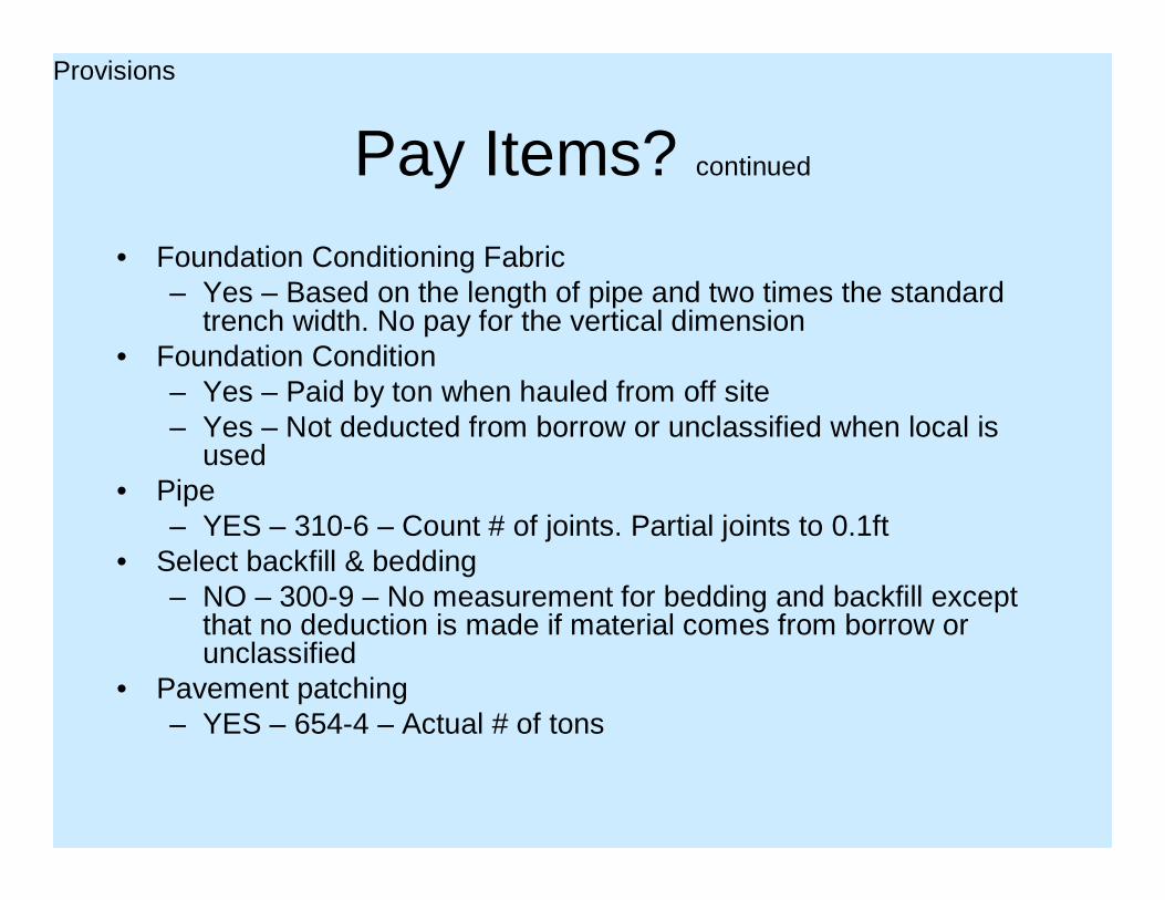
Pay Items? continued
• Foundation Conditioning Fabric – Yes – Based on the length of pipe and two times the standard
trench width. No pay for the vertical dimension• Foundation Condition
– Yes – Paid by ton when hauled from off site– Yes – Not deducted from borrow or unclassified when local is
used• Pipe
– YES – 310-6 – Count # of joints. Partial joints to 0.1ft• Select backfill & bedding
– NO – 300-9 – No measurement for bedding and backfill except that no deduction is made if material comes from borrow or unclassified
• Pavement patching– YES – 654-4 – Actual # of tons
Provisions

Drainage Structure Number Scheme
• This convention will combine the plan page number with the sequential number of the drainage structure on that particular plan sheet. So, the first pipe outlet or drainage structure on plan sheet 25 will be identified as 2501.
• This is an aid in the design phase and should assist in quickly referencing drainage during construction.
Design

Revised network numbering scheme
• First two numbers = plan sheet number• Next two numbers = drainage structure
number• Numbers start over with each sheet
Design

Design
Structure# 2501
Structure# 2502
Sheet# 25

SummaryPay Items & Miscellaneous
• Incidental–Pavement, island, sidewalk, etc. removal–Excavation–Fabric pipe wrap–All bedding–Backfill up to 1’ above flexible pipe & up to springline for rigid pipe
• Possible Pay Item–Pipe removal–Undercut–Draining foundation
• Pay Item–Foundation Conditioning–Fabric wrapping foundation conditioning–Pipe–Patching
• Network Numbering

Critical Inspection Points
• When pipe is delivered• At bottom of excavation• Placing fabric and select CL V(78) or VI(57)• Placing Select CL III or II• Bailing pipe• Compacting haunch• Backfill to spring line• Conducting pipe density
Looks like pretty much the entire time doesn’t it

Possible failures and causes• Cracking and deformation
– Too little cover • Crack > 0.1” = replace• Crack > 0.01” = repair or replace• Deformation
– Pour backfill technique• Too little cover during construction (as materials are being hauled)
– Not ramped with 3’ minimum cover. Take care when min imum cover is used if there is hauling to take place. Earthen ra mps placed to protect pipes will be removed just prior to fine grading.
• Joint separation– Constant inspection prior to backfill
• Connections to drainage structures fail– Grout cracks – Short joint of pipe (air brick)
• Damage from other operations– Guardrail– Signs– Signal drilling

Keys to Success
• Inspection• Foundation• Inspection• Backfill• Inspection• Joints• Inspection• Cover• Inspection