Embed Size (px)
Citation preview

Pipe InstallationHandbook
Straight Socket and
Butt & Wrap Joints
•CENTRICAST® PRODUCTSCL-1520CL-2030
RB-1520RB-2530
•F-CHEM®•Z-CORE®
www.fgspipe.com


NOVFIBERGLASSSYSTEMSPIPEINSTALLATIONHANDBOOK
StraightSocketJointsandButt&WrapJoints
This fabrication manual is offered to assist you in the proper fabrication and installation procedures when assembling your NOV Fiber Glass Systems piping system.
If you do not find the answer to your questions in the manual, feel free to contact your Regional Manager, local distributor, or the factory.
The products must be installed and used in accordance with sound, proven practice and common sense.
The information supplied in our literature must be con-sidered as an expression of guidelines based on field experience rather than a warranty for which we assume responsibility. NOV Fiber Glass Systems offers a limited warranty of its products in the Terms and Conditions of Sale. The information contained in the literature and catalogs furnished cannot ensure, of itself, a successful installation and is offered to customers subject to these limitations and explanations.
It is our policy to improve its products continually. Therefore, the company reserves the right, without notice, to change specifications and/or design at any time without incurring an obligation for equipment previously sold. Descriptions contained in this catalog are for the purpose of identification and neither limit nor extend the standard product limited warranty set forth in the Terms and Conditions of Sale and Trade Customs.
ii
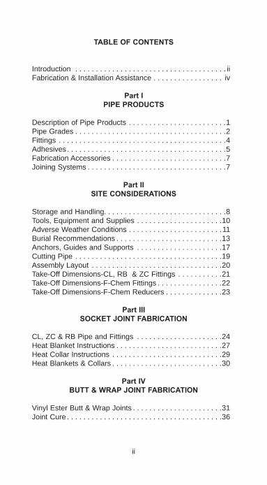
TABLEOFCONTENTS
Introduction . . . . . . . . . . . . . . . . . . . . . . . . . . . . . . . . . . . . . iiFabrication & Installation Assistance . . . . . . . . . . . . . . . . . iv
PartIPIPEPRODUCTS
Description of Pipe Products . . . . . . . . . . . . . . . . . . . . . . . .1Pipe Grades . . . . . . . . . . . . . . . . . . . . . . . . . . . . . . . . . . . . .2Fittings . . . . . . . . . . . . . . . . . . . . . . . . . . . . . . . . . . . . . . . . .4Adhesives. . . . . . . . . . . . . . . . . . . . . . . . . . . . . . . . . . . . . . .5Fabrication Accessories . . . . . . . . . . . . . . . . . . . . . . . . . . . .7Joining Systems . . . . . . . . . . . . . . . . . . . . . . . . . . . . . . . . . .7
PartIISITECONSIDERATIONS
Storage and Handling. . . . . . . . . . . . . . . . . . . . . . . . . . . . . .8Tools, Equipment and Supplies . . . . . . . . . . . . . . . . . . . . .10Adverse Weather Conditions . . . . . . . . . . . . . . . . . . . . . . .11Burial Recommendations . . . . . . . . . . . . . . . . . . . . . . . . . .13Anchors, Guides and Supports . . . . . . . . . . . . . . . . . . . . .17Cutting Pipe . . . . . . . . . . . . . . . . . . . . . . . . . . . . . . . . . . . .19Assembly Layout . . . . . . . . . . . . . . . . . . . . . . . . . . . . . . . .20Take-Off Dimensions-CL, RB & ZC Fittings . . . . . . . . . . .21Take-Off Dimensions-F-Chem Fittings . . . . . . . . . . . . . . . .22Take-Off Dimensions-F-Chem Reducers . . . . . . . . . . . . . .23
PartIIISOCKETJOINTFABRICATION
CL, ZC & RB Pipe and Fittings . . . . . . . . . . . . . . . . . . . . .24Heat Blanket Instructions . . . . . . . . . . . . . . . . . . . . . . . . . .27Heat Collar Instructions . . . . . . . . . . . . . . . . . . . . . . . . . . .29Heat Blankets & Collars . . . . . . . . . . . . . . . . . . . . . . . . . . .30
PartIVBUTT&WRAPJOINTFABRICATION
Vinyl Ester Butt & Wrap Joints . . . . . . . . . . . . . . . . . . . . . .31Joint Cure . . . . . . . . . . . . . . . . . . . . . . . . . . . . . . . . . . . . . .36
ii
PartVINSTALLATIONCONSIDERATIONS
Flange & Fitting Alignment . . . . . . . . . . . . . . . . . . . . . . . . .37Flange Gasket & O-Ring Requirements. . . . . . . . . . . . . . .40Standard Bolting Conditions. . . . . . . . . . . . . . . . . . . . . . . .41Flange Bolt Torque Sequence . . . . . . . . . . . . . . . . . . . . . .44Special Flange Bolting Conditions . . . . . . . . . . . . . . . . . . .46Connecting to Other Piping Systems . . . . . . . . . . . . . . . . .47Hydrostatic Testing . . . . . . . . . . . . . . . . . . . . . . . . . . . . . . .48System Startup. . . . . . . . . . . . . . . . . . . . . . . . . . . . . . . . . .48Water Hammer . . . . . . . . . . . . . . . . . . . . . . . . . . . . . . . . . .50
PartVISYSTEMREPAIR&MODIFICATION
Replacing Damaged Pipe. . . . . . . . . . . . . . . . . . . . . . . . . .51Replacing Damaged Fittings . . . . . . . . . . . . . . . . . . . . . . .53Overwrap . . . . . . . . . . . . . . . . . . . . . . . . . . . . . . . . . . . . . .55Temporary Fixes. . . . . . . . . . . . . . . . . . . . . . . . . . . . . . . . .56Tapping into a Line . . . . . . . . . . . . . . . . . . . . . . . . . . . . . . .56
PartVIIHELPFULINFORMATION
Conversions . . . . . . . . . . . . . . . . . . . . . . . . . . . . . . . . . . . .59Useful Formulas . . . . . . . . . . . . . . . . . . . . . . . . . . . . . . . .65Definition of Terms . . . . . . . . . . . . . . . . . . . . . . . . . . . . . . .66How To Read Flanged or Reducing Fittings . . . . . . . . . . .71How To Figure a 45° Offset . . . . . . . . . . . . . . . . . . . . . . . .72
iii
CL= Centricast®PlusCL-2030or Centricast®CL-1520PipingSystemsRB= Centricast®PlusRB-2530or Centricast®RB-1520PipingSystemsZC= Z-Core®PipingSystemsFC= F-Chem®PipingSystems
FABRICATIONANDINSTALLATIONASSISTANCE
Installing fiberglass pipe is easier than installing carbon steel, stainless steel and lined steel due to light weight. Learning the proper methods to prepare and make-up socket or butt & wrap joints can help ensure the reliability and long-term per-formance of your piping system.
We offer the TQI Plus (ASME B31.3) Fabrication and Assembly certification program. Qualified Field Service Representatives train fabrication and assembly crews, conduct and supervise fabrication work, and inspect work in progress.
For complete information concerning these training seminars, contact your local distributor or Regional Manager.
iv
CAUTIONAs this pipe may carry hazardous material and/or operate at a hazardous pressure level, you must follow instructions in this manual to avoid serious personal injury or property damage. In any event, improper installation can cause injury or damage. In addition, installers should read and follow all cautions and warn-ings on adhesive kits, heat packs, propane torches, etc. to avoid personal injury. Also, observe general safety practices with all saws, tools, etc. to avoid personal injury. Wear protective clothing when necessary. Make sure work surfaces are clean and stable and that work areas are properly ventilated.
MaterialSafetyDataSheets(MSDS)areavailableonourwebsiteatwww.fgspipe.com.

PARTIPIPEPRODUCTS
DESCRIPTIONOFPIPEPRODUCTSThe performance characteristics of a fiberglass pipe system depend on several important elements including the resin and curing agent, as well as the manufacturing process and type and thickness of the pipe’s corrosion barrier.
Our piping systems are manufactured using epoxy, vinyl ester, or isophthalic polyester resin systems. All are heat cured for optimum chemical resistance and physical properties. Match your temperature, pressure and chemical resistance require-ments to the piping system.
Fiberglasspipingsystemsoffer:a. Smooth iron pipe size O.D.b. Used with standard IPS pipe hangersc. High strength for long spansd. Excellent corrosion resistancee. Lightweightf. Complete line of fittings and accessories availableg. Costs can be optimized by selecting pipe grades for
specific servicesh. Full vacuum capability in premium gradesi. Easy to repair if damaged
CentrifugallyCastPipeCentrifugally cast FRP pipe (Centricast) consists of reinforce-ment fabric layers saturated with thermosetting resin, then cured in a casting machine. Cast pipe features a pure resin interior barrier for maximum corrosion resistance. The glass fabric gives the pipe its structural strength and the resin pro-vides the corrosion resistance. Pipe is available in premium epoxy (ZC), epoxy (RB) and vinyl ester (CL) resin grades.
a. Sizes 1" - 14" diameterb. Straight socket adhesive joint methodc. No special fabrication tools requiredd. 10 mil resin-rich exterior resistant to UV attack
FilamentWoundPipeOur filament wound pipe begins with resin-saturated fiberglass or other man-made materials as an inner liner or corrosion barrier. The liner is then covered with a resin impregnated fila-ment wound matrix of fiberglass. The matrix is applied under controlled tension in a predetermined pattern to the specified wall thickness.
1

Custom Filament Wound Product (F-Chem) is available in epoxy, vinyl ester, isophthalic polyester and fire retardant resin grades.
a. Sizes 1" - 72" diameterb. Joining methods include: • Plain end butt and wrap • Matched tapered bell & spigot c. No special fabrication tools required
PIPEGRADESCENTRICASTPLUSRB-2530Highly corrosion resistant epoxy pipe grade handles most caustics, salts, solvents, many acids and chemical process solutions up to 250°F, 100 mil pure resin corrosion bar-rier. Pipe has durable heavy wall construction for long spans, great impact resistance, tensile, bending and compressive strengths.
CENTRICASTRB-1520Epoxy pipe grade recommended for many caustics, acids, salts, solvents and chemical process solutions up to 250°F, 50 mil pure resin corrosion barrier. Pipe has long spans, integral socket joints, and low thermal expansion loads for the lowest installed cost.
Z-COREPremium epoxy pipe with proprietary resin for outstanding corrosion resistance to aggressive solvents and strong acids, including 98% sulfuric acid. Rated for temperatures up to 275°F, 100 mil resin-rich liner. Heavy wall construction for great impact resistance, long spans and low thermal expan-sion.
CENTRICASTPLUSCL-2030Highly corrosion resistant vinyl ester pipe grade used for over 25 years in the harshest hot acid, chlorine, and other chemi-cal services up to 200°F, 100 mil pure resin corrosion barrier also provides impact and abrasion resistance. Pipe has high strength heavy wall construction.
CENTRICASTCL-1520Vinyl ester pipe grade used for many hot acid, chlorine and corrosive chemical services up to 200°F, 50 mil pure resin corrosion barrier. Long spans, integral socket joints, and low thermal expansion loads provide for a low installed cost system.
2

F-CHEMandF-CHEMAR*Custom filament wound construction offers more flexibility in resin systems, corrosion barriers and wall thickness than our standard products. Let us assist you in selecting the right pipe for a specific application.
*AR grade is manufactured for added abrasion resistance.
3
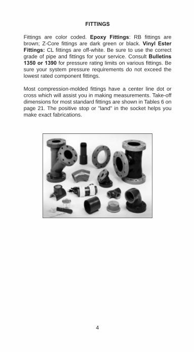
FITTINGS
Fittings are color coded. Epoxy Fittings: RB fittings are brown; Z-Core fittings are dark green or black. Vinyl EsterFittings: CL fittings are off-white. Be sure to use the correct grade of pipe and fittings for your service. Consult Bulletins1350or1390 for pressure rating limits on various fittings. Be sure your system pressure requirements do not exceed the lowest rated component fittings.
Most compression-molded fittings have a center line dot or cross which will assist you in making measurements. Take-off dimensions for most standard fittings are shown in Tables 6 on page 21. The positive stop or "land" in the socket helps you make exact fabrications.
4

ADHESIVES
Adhesives are formulated for specific use with the companion pipe grades. Use only the recommended adhesive with each pipe grade - do not mix systems! Standard adhesives are a two-component system (Parts A and B) which must be mixed prior to use. CL-200 Quick Set (QS) adhesives are available for reduced cure time where necessary. Detailed instruc-tionsforadhesivesareprovidedwitheachkit. Read these instructions thoroughly and follow the recommended proce-dures. The pot life and cure time of the adhesive is dependent on temperature; refer to pages 6, 28, 30, and 36. Ambient temperatures above 100°F require extra care by the fabrica-tor to assure sufficient working time of the adhesive. Refer to Adverse Weather Recommendations on page 11.
ADHESIVESELECTION
Standard adhesive kits are designed to be used with specific piping systems as shown below.
TABLE1.AdhesiveSelection
Usewiththese
pipingsystems
KitNumber(1)(2)(3)
MaximumService
Temperature
Z-Core Weldfast® ZC-275 275°F
Centricast PlusCL-2030 & CL1520
Weldfast CL-200 200°F
Centricst PlusCL-2030 CL-1520
Weldfast CL-200 QS(4) 200°F
Centricast PlusRB-2530 & RB-1520
Weldfast ZC-275 250°F
F-Chem Vinyl EsterButt Weld Kit 250°F
NOTES:1. Although all of the adhesives will cure at ambient tempera-
tures above 70°F, it is recommended they be heat-cured at temperatures of at least 275°F to maximize physical properties and corrosion resistance. See pages 27-30 for instructions for using heat blankets or collars for heat-curing joints.
5
2. For complete detailed instructions on using adhesive, refer to the step-by-step instruction bulletin included in the adhesive kits.
3. Refer to Chemical Resistance Guide, Bulletin No. E5615 for adhesive chemical resistance rating.
4. Quick-set adhesive for use when faster cure time is required and the ambient temperature is below 90°F. Weldfast CL-200-QS is the same as Weldfast CL-200 except a third compo-nent, Part C, has been added to the kit.
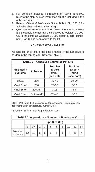
ADHESIVEWORKINGLIFE
Working life or pot life is the time it takes for the adhesive to harden in the mixing can. Refer to Table 2.
TABLE2.AdhesivesEstimatedPotLife
PipeResinSystems Adhesive
PotLive@70°F(min.)
(seenote)
PotLive@90°F(min.)
(seenote)Epoxy 275 30-40 15-25
Vinyl Ester 200 20-30 6-12
Vinyl Ester 200QS 7-15 4-7
Vinyl Ester Butt Weld* 20-40 8-15
NOTE: Pot life is the time available for fabrication. Times may vary depending upon temperature, humidity, etc.
* Based on 16 ml of catalyst per quart of resin.
TABLE3.ApproximateNumberofBondsperKitPipeSize(In.)
1 11⁄2 2 3 4 6 8 10 12 14
Number of Joints 12 10 8 5 3 2 1 1⁄2 1⁄2 1⁄3
6
FABRICATIONACCESSORIES
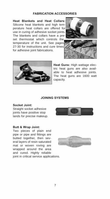
Heat Blankets and Heat Collars: Silicone heat blankets and high tem-perature heat collars are offered for use in curing of adhesive socket joints. The blankets and collars have a pre-set thermostat which controls the temperature of the unit. See pages 27-30 for instructions and cure times for adhesive joint fabrications.
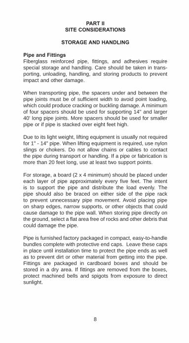
HeatGuns:High wattage elec-tric heat guns are also avail-able to heat adhesive joints. The heat guns are 1600 watt capacity.
JOININGSYSTEMS
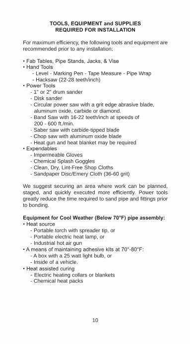
SocketJoint:Straight socket adhesive joints have positive stop lands for precise makeup.
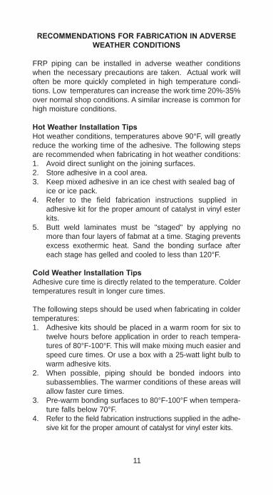
Butt&WrapJoint:Two pieces of plain end pipe or pipe and fittings are butted together, then sev-eral layers of resin saturated mat or woven roving are wrapped around the area and cured. Highly reliable joint in critical service applications.
7
PARTIISITECONSIDERATIONS
STORAGEANDHANDLING
PipeandFittingsFiberglass reinforced pipe, fittings, and adhesives require special storage and handling. Care should be taken in trans-porting, unloading, handling, and storing products to prevent impact and other damage.
When transporting pipe, the spacers under and between the pipe joints must be of sufficient width to avoid point loading, which could produce cracking or buckling damage. A minimum of four spacers should be used for supporting 14" and larger 40' long pipe joints. More spacers should be used for smaller pipe or if pipe is stacked over eight feet high.
Due to its light weight, lifting equipment is usually not required for 1" - 14" pipe. When lifting equipment is required, use nylon slings or chokers. Do not allow chains or cables to contact the pipe during transport or handling. If a pipe or fabrication is more than 20 feet long, use at least two support points.
For storage, a board (2 x 4 minimum) should be placed under each layer of pipe approximately every five feet. The intent is to support the pipe and distribute the load evenly. The pipe should also be braced on either side of the pipe rack to prevent unnecessary pipe movement. Avoid placing pipe on sharp edges, narrow supports, or other objects that could cause damage to the pipe wall. When storing pipe directly on the ground, select a flat area free of rocks and other debris that could damage the pipe.
Pipe is furnished factory packaged in compact, easy-to-handle bundles complete with protective end caps. Leave these caps in place until installation time to protect the pipe ends as well as to prevent dirt or other material from getting into the pipe. Fittings are packaged in cardboard boxes and should be stored in a dry area. If fittings are removed from the boxes, protect machined bells and spigots from exposure to direct sunlight.
8

Pipe can be damaged when joints or bundles of pipe are dropped during handling or shipping. Severe localized impact blows may result in damage to the fiberglass reinforced structure in the pipe wall. Before installation, inspect thepipe's outer surface and inner surface (if possible) forany damage. Do not use damaged pipe unless inspected and approved by a company representative. If impact dam-age occurs, the damaged areas may be recognized by a star type fracture on the interior of cast pipe or the exterior of fila-ment wound pipe. Pipe that has been damaged should have a length cut away approximately one foot either side of the damaged or cracked area.
Note: Do not allow the bell end of the pipe to support any pipe weight. Do not allow deformation of the pipe due to supports or straps.
AdhesiveVinyl ester adhesives can be damaged by storage in warm places. We recommend adhesives be stored in a dry area where temperatures do not exceed 80° F. Refer to adhesive instructions included in each kit for storage life recommenda-tions.
9
TOOLS,EQUIPMENTandSUPPLIESREQUIREDFORINSTALLATION
For maximum efficiency, the following tools and equipment are recommended prior to any installation:
• Fab Tables, Pipe Stands, Jacks, & Vise• Hand Tools - Level - Marking Pen - Tape Measure - Pipe Wrap - Hacksaw (22-28 teeth/inch)• Power Tools - 1" or 2" drum sander - Disk sander - Circular power saw with a grit edge abrasive blade, aluminum oxide, carbide or diamond. - Band Saw with 16-22 teeth/inch at speeds of 200 - 600 ft./min. - Saber saw with carbide-tipped blade - Chop saw with aluminum oxide blade - Heat gun and heat blanket may be required• Expendables - Impermeable Gloves - Chemical Splash Goggles - Clean, Dry, Lint-Free Shop Cloths - Sandpaper Disc/Emery Cloth (36-60 grit) We suggest securing an area where work can be planned, staged, and quickly executed more efficiently. Power tools greatly reduce the time required to sand pipe and fittings prior to bonding.
EquipmentforCoolWeather(Below70°F)pipeassembly:• Heat source - Portable torch with spreader tip, or - Portable electric heat lamp, or - Industrial hot air gun• A means of maintaining adhesive kits at 70°-80°F: - A box with a 25 watt light bulb, or - Inside of a vehicle.• Heat assisted curing - Electric heating collars or blankets - Chemical heat packs
10
RECOMMENDATIONSFORFABRICATIONINADVERSEWEATHERCONDITIONS
FRP piping can be installed in adverse weather conditions when the necessary precautions are taken. Actual work will often be more quickly completed in high temperature condi-tions. Low temperatures can increase the work time 20%-35% over normal shop conditions. A similar increase is common for high moisture conditions.
HotWeatherInstallationTipsHot weather conditions, temperatures above 90°F, will greatly reduce the working time of the adhesive. The following steps are recommended when fabricating in hot weather conditions:1. Avoid direct sunlight on the joining surfaces.2. Store adhesive in a cool area.3. Keep mixed adhesive in an ice chest with sealed bag of
ice or ice pack. 4. Refer to the field fabrication instructions supplied in
adhesive kit for the proper amount of catalyst in vinyl ester kits.
5. Butt weld laminates must be "staged" by applying no more than four layers of fabmat at a time. Staging prevents excess exothermic heat. Sand the bonding surface after each stage has gelled and cooled to less than 120°F.
ColdWeatherInstallationTipsAdhesive cure time is directly related to the temperature. Colder temperatures result in longer cure times.
The following steps should be used when fabricating in colder temperatures:1. Adhesive kits should be placed in a warm room for six to
twelve hours before application in order to reach tempera-tures of 80°F-100°F. This will make mixing much easier and speed cure times. Or use a box with a 25-watt light bulb to warm adhesive kits.
2. When possible, piping should be bonded indoors into subassemblies. The warmer conditions of these areas will allow faster cure times.
3. Pre-warm bonding surfaces to 80°F-100°F when tempera-ture falls below 70°F.
4. Refer to the field fabrication instructions supplied in the adhe-sive kit for the proper amount of catalyst for vinyl ester kits.
11
5. A heat gun, collar or blanket may be used to obtain a faster cure time. Apply a layer of fiberglass insulation or a welding blanket around the heat collars or blankets when installation temperatures are below 50°F.
ExtremeMoisture
AdhesiveJoints• If fittings or pipe have moisture on the bonding surface,
wipe them dry prior to sanding.• Sand pipe or fittings immediately before applying the adhe-
sive to bond the joint. Sand surfaces until a fresh, dry surface is present, then remove dust with a clean dry cloth, and apply adhesive.
• Cure per the previous recommendations for normal, extreme heat or extreme cold temperatures.
LaminateJoints• Keep the glass fabric dry, as resins will not saturate wet
fabric. Discard glass fabric which has been wet or exposed to rain, as moisture can remove the bonding agent.
• In high humidity environments, keep the glass fabric in the plastic wrap until ready to use.
• If it is raining, move the work to a shelter, or construct a temporary shelter.• Bonding surfaces must be sanded immediately prior to application of the resin to the pipe or fitting. Sand or grind
until a fresh, dry surface is present, then wipe off the dust and apply resin.
• Saturate the fabric with the resin and apply a coat of resin to the sanded surface prior to applying the fabric.
• Refer to recommendations for conditions of extreme heat, cold, or normal conditions for curing.
• When a laminate requires staging, repeat the above pre-cautions for each step.
• Moisture will not affect the cured laminate joint.
12
BURIALRECOMMENDATIONS
These are general guidelines only. For more details see Engineering and Piping Design Guide E5000.
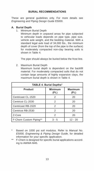
A. BurialDepth1. Minimum Burial Depth Minimum depth in unpaved areas for pipe subjected
to vehicular loads depends on pipe type, pipe size, vehicle axle weight, and the bedding material. With a standard legal axle load of 34,000 lbs., the minimum depth of cover (from the top of the pipe to the surface) for moderately compacted non-clay bearing soils is shown in Table 4.
The pipe should always be buried below the frost line.
2. Maximum Burial Depth Maximum burial depth is dependent on the backfill
material. For moderately compacted soils that do not contain large amounts of highly expansive clays, the maximum burial depth is shown in Table 4.
TABLE4.BurialDepths*Product Minimum
(Ft.)Maximum
(Ft.)Centricast CL-1520 2 20
Centricst CL-2030 2 20
Centricast RB-1520 2 20
Centricst RB-2530 2 20
Z-Core 2 20
F-Chem Custom Piping** 3 - 5 12 - 20
* Based on 1000 psi soil modulus. Refer to Manual No. E5000, Engineering & Piping Design Guide, for detailed information for your specific application.
** F-Chem is designed for specific burial applications accord-ing to AWWA M45.
13
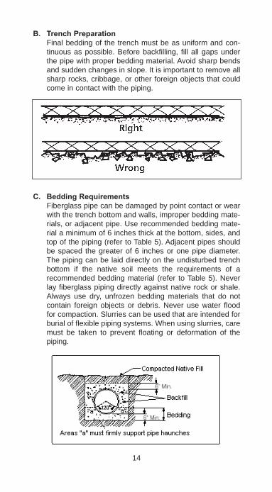
B. TrenchPreparation Final bedding of the trench must be as uniform and con-
tinuous as possible. Before backfilling, fill all gaps under the pipe with proper bedding material. Avoid sharp bends and sudden changes in slope. It is important to remove all sharp rocks, cribbage, or other foreign objects that could come in contact with the piping.
C. BeddingRequirements Fiberglass pipe can be damaged by point contact or wear
with the trench bottom and walls, improper bedding mate-rials, or adjacent pipe. Use recommended bedding mate-rial a minimum of 6 inches thick at the bottom, sides, and top of the piping (refer to Table 5). Adjacent pipes should be spaced the greater of 6 inches or one pipe diameter. The piping can be laid directly on the undisturbed trench bottom if the native soil meets the requirements of a recommended bedding material (refer to Table 5). Never lay fiberglass piping directly against native rock or shale. Always use dry, unfrozen bedding materials that do not contain foreign objects or debris. Never use water flood for compaction. Slurries can be used that are intended for burial of flexible piping systems. When using slurries, care must be taken to prevent floating or deformation of the piping.
14
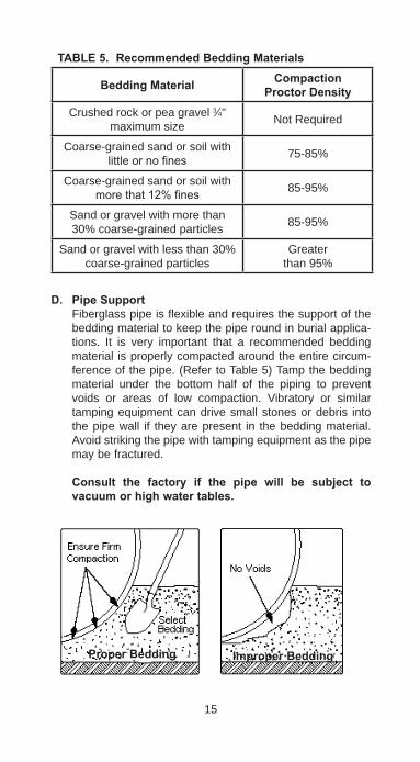
TABLE5.RecommendedBeddingMaterials
BeddingMaterial CompactionProctorDensity
Crushed rock or pea gravel 3⁄4" maximum size Not Required
Coarse-grained sand or soil with little or no fines 75-85%
Coarse-grained sand or soil with more that 12% fines 85-95%
Sand or gravel with more than 30% coarse-grained particles 85-95%
Sand or gravel with less than 30% coarse-grained particles
Greater than 95%
D. PipeSupport Fiberglass pipe is flexible and requires the support of the
bedding material to keep the pipe round in burial applica-tions. It is very important that a recommended bedding material is properly compacted around the entire circum-ference of the pipe. (Refer to Table 5) Tamp the bedding material under the bottom half of the piping to prevent voids or areas of low compaction. Vibratory or similar tamping equipment can drive small stones or debris into the pipe wall if they are present in the bedding material. Avoid striking the pipe with tamping equipment as the pipe may be fractured.
Consult the factory if the pipe will be subject to vacuumorhighwatertables.
15
ProperBedding ImproperBedding

E. RoadCrossings When laying fiberglass
pipe under road cross-ings, it may be neces-sary to pass the pipe through conduit to protect the pipe. Pad the pipe to prevent rubbing or point loads against the conduit.
F. WallPenetrations Where the pipe goes through or passes under a concrete
structure, precautions must be taken to prevent bending or point loading of the pipe due to settling. A minimum 2" thick pad of resilient material should be wrapped around the pipe to provide flexibility and prevent contact with the concrete. If bolts are used in the resilient material, care should be taken that the bolts, nuts, or washers cannot come into point load contact with the pipe. Bedding depth under the pipe should be increased to a minimum of 12" or one pipe diameter, whichever is greater, for one pipe joint length away from the concrete.
G. Timing Test and cover the pipe as soon as possible to reduce the
chance of damage to the pipe, floating of the pipe due to flooding, or shifting of the line due to cave-ins.
16
Thick Pad of Resilient Material
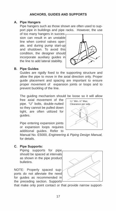
ANCHORS,GUIDESANDSUPPORTS
A. PipeHangers Pipe hangers such as those shown are often used to sup-
port pipe in buildings and pipe racks. However, the use of too many hangers in succes-sion can result in an unstable line when control valves oper-ate, and during pump start-up and shutdown. To avoid this condition, the designer should incorporate auxiliary guides in the line to add lateral stability.
B. PipeGuides Guides are rigidly fixed to the supporting structure and
allow the pipe to move in the axial direction only. Proper guide placement and spacing are important to ensure proper movement of expansion joints or loops and to prevent buckling of the line.
The guiding mechanism should be loose so it will allow free axial movement of the pipe. “U” bolts, double-nutted so they cannot be pulled down tight, are often utilized for guides.
Pipe entering expansion joints or expansion loops requires additional guides. Refer to Manual No. E5000, Engineering & Piping Design Manual, for details.
C. PipeSupports: Piping supports for pipe
should be spaced at intervals as shown in the pipe product bulletins.
NOTE: Properly spaced sup-ports do not alleviate the need for guides as recommended in the preceding section. Supports that make only point contact or that provide narrow support-
17
1⁄16" Min.-1⁄8" Max. Clearance per side

ing areas should be avoided. Some means of increasing the supporting area should be used; sleeves made from half of a coupling or pipe are suitable. Support pumps, valves and other heavy equipment independent of the pipe. Refer to pump and valve connection instructions on page 48.
D. PipeAnchors: Pipe anchors divide a pipeline into individual expanding
sections. In most applications, major pieces of con-nected equipment, such as pumps and tanks, function as anchors. Additional anchors are usually located at valves, near changes in direction of the pip-ing, at blind ends of pipe, and at major branch connec-tions. Provisions for expansion should be designed into each of the individ-ual pipe sections.
Do not install more than one expansion joint or expansion loop between two anchors.
Do not anchor pipe by applying external pressure as point loads, such as a "U"-bolt, directly to the bare pipe.
Refer to Manual No. E5000, Engineering & Piping Design, for a thorough discussion on supports, anchors and guides.
18
Anchor Sleeves
Clamp, snug but not tight
Weld or bolt anchor to support member
Snug fit
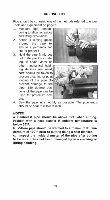
CUTTINGPIPE
Pipe should be cut using one of the methods referred to under Tools and Equipment on page 10.1. Measure pipe, remem-
bering to allow for spigot and fitting dimensions.
2. Scribe a cutting guide around the pipe to ensure a perpendicular cut for proper fit.
3. Hold the pipe firmly but not to the point of crush-ing. If chain vises or other mechanical hold-ing devices are used, care should be taken to prevent crushing or point loading of the pipe. To prevent damage to the pipe, 180 degree sec-tions of the pipe can be used for protective cov-ers.
4. Saw the pipe as smoothly as possible. The pipe ends should be square within 1⁄8 inch.
NOTES:a. Centricast pipe should be above 55°F when cutting.Preheat with a heat blanket if ambient temperature isbelow55°F.b.Z-CorepipeshouldbewarmedtoaminimumIDtem-peratureof100°Fpriortocuttingusingaheatblanket.c. Inspect the inside diameter of the pipe after cuttingtobesure ithasnotbeendamagedbysawcrackingorduringhandling.
19

ASSEMBLYLAYOUT
Refer to Table 6 on page 21 for "Take-Off Dimensions" for socket joint fittings or Tables 8 and 9 on pages 22-23 for F-Chem fittings. The method for calculation is similar to the method for any other piping system:a. Determine the required finished length of the pipe spool sections from the drawing.b. Subtract the take-off dimension for each fitting in the
spool section.c. Cut the pipe to the length determined as the take-off
dimension (b. above).d. As a double check, dry fit the pipe and fitting(s) to con-
firm the finished length is correct. e. Mark the cut pipe lengths with the pipe spool identifica-
tion number from the blueprint to avoid later confusion. Many pipe lengths can be cut at one time to allow improved efficiency in pipe fabrication.
Consult Fittings & Accessories Bulletins for complete fittingdimensions and other data.
20

21
TABLE
6.Take-offD
imension
sforC
L,RB&Z
CSocketF
ittings
Pip
e st
op to
fitti
ngs’
cen
ter l
ine
dim
ensi
ons.
The
dim
ensi
ons
are
used
to c
alcu
late
pip
e le
ngth
requ
irem
ents
to m
eet p
ipel
ine
cent
er li
ne to
ce
nter
line
dim
ensi
ons.
Size
Fig.265C
45°E
lbow
Fig.255C
90°E
lbow
Fig.275C
Tee
Fig.266C
Fig.285C
Cross
Fig.257C
LR90°Elbow
PMHLU
PMHLU
AB
In.
In.
In.
In.
In.
In.
In.
In.
In.
In.
115 ⁄1
69 ⁄1
615 ⁄1
615 ⁄1
625 ⁄1
6-
--
313⁄16
11 ⁄21
15⁄16
17 ⁄16
17 ⁄16
211⁄16
--
-411
⁄162
17 ⁄16
11⁄16
22
211⁄16
511⁄16
13⁄16
13 ⁄8411
⁄163
115⁄16
13 ⁄16
25 ⁄825 ⁄8
311⁄16
71 ⁄811 ⁄8
23 ⁄16
515⁄16
421 ⁄4
23 ⁄16
31 ⁄431 ⁄4
411⁄16
93 ⁄16
7 ⁄831 ⁄2
73 ⁄16
6215
⁄1633 ⁄1
643 ⁄1
643 ⁄1
663 ⁄1
615
9 ⁄16
55 ⁄16
43 ⁄16
98
-35 ⁄1
647 ⁄8
-51 ⁄1
618
11⁄16
55 ⁄16
53 ⁄16
1210
-311
⁄16-
-83 ⁄1
622
7 ⁄16
67 ⁄16
83 ⁄16
1311
⁄1612
-411
⁄16-
-93 ⁄1
627
15⁄16
75 ⁄16
93 ⁄16
163 ⁄1
6
14-
53 ⁄8-
-95 ⁄8
--
-18
22
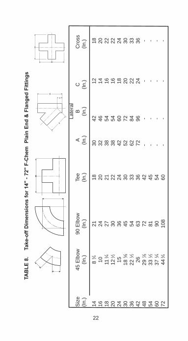
TABLE
8.Take-offD
imension
sfor1
4"-72"F-ChemP
lainEnd
&Flang
edFittings
La
tera
lS
ize
45 E
lbow
90
Elb
ow
Tee
A B
C
Cro
ss
(In.)
(In.)
(In.)
(In.)
(In.)
(In.)
(In.)
(In
.)
14
8 3 ⁄4
21
18
30
42
12
18
16
10
24
20
32
46
14
2018
11
1⁄4
27
21
38
54
16
2220
12
1⁄2
30
22
38
54
16
2224
15
36
24
42
60
18
24
30
18 5 ⁄8
45
30
52
72
20
30
36
22 1 ⁄2
54
33
62
84
22
33
42
26
63
36
72
96
24
3648
29
7 ⁄8
72
42
- -
-
-
54
33 1 ⁄2
81
45
-
-
-
-60
37
1 ⁄4
90
54
- -
-
-
72
44 3⁄4
108
60
- -
-
-
C
B
A

23
TABLE
9.Take-offD
imension
sfor1
4"-72"F-ChemP
lainEnd
&Flang
edReducers
Siz
e (I
n.)
A B
C
D
E
F
G
H
14X
10
10
10
14 1 ⁄4
16
18
3⁄4
2114
X12
5
10
17
19
18 3 ⁄4
21
16X
12
10
10
17
19
21 3 ⁄4
23
1 ⁄216
X14
5
12
18 3 ⁄4
21
21
3 ⁄4
23 1⁄2
18X
14
10
12
18 3 ⁄4
21
22
3 ⁄4
2518
X16
5
12
21 1 ⁄4
23
1⁄2
22 3 ⁄4
25
20X
16
10
12
21 1⁄4
23 1 ⁄2
25
27
1 ⁄220
X18
5
12
22 3 ⁄4
25
25
27
1 ⁄224
X18
15
12
22
3 ⁄4
25
29 1 ⁄2
32
24X
20
10
12
25
27 1 ⁄2
29
1 ⁄2
3230
X20
25
12
25
27
1 ⁄2
36
38 3 ⁄4
30X
24
15
12
29 1 ⁄2
32
36
38
3 ⁄436
X24
30
12
29
1 ⁄2
32
42 3 ⁄4
46
36X
30
15
15
38 3 ⁄4
36
42
3 ⁄4
4642
x30
30
15
38
3 ⁄4
36
49 1⁄2
5342
x36
15
15
42
3 ⁄4
46
49 1 ⁄2
53
Pla
in E
nd E
ccen
tric
Pla
in E
nd C
once
ntric
Flan
ged
Ecc
entri
c
Flan
ged
Con
cent
ric
PARTIIISOCKETJOINTFABRICATION
Straight socket adhesive joints are designed for: 1. High strength 2. Easy, quick fabrications 3. Minimum of tools and procedures 4. High reliabilityThe adhesives provide reinforcement in the bond area and are designed to prevent void areas. There are only a few important procedures, but you must follow them correctly to achieve a good bond. (Note: Follow complete detailed instructions sup-plied with each adhesive kit.)
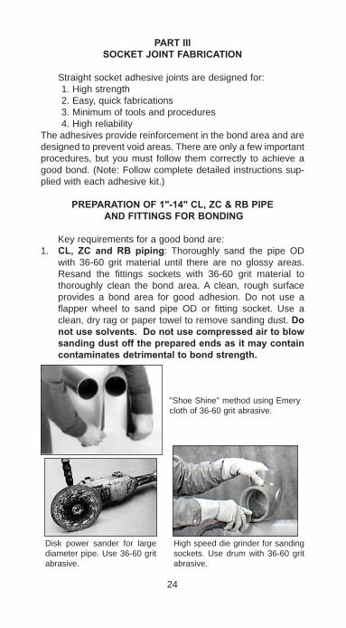
PREPARATIONOF1"-14"CL,ZC&RBPIPE ANDFITTINGSFORBONDING
Key requirements for a good bond are:1.CL, ZC and RB piping: Thoroughly sand the pipe OD
with 36-60 grit material until there are no glossy areas. Resand the fittings sockets with 36-60 grit material to thoroughly clean the bond area. A clean, rough surface provides a bond area for good adhesion. Do not use a flapper wheel to sand pipe OD or fitting socket. Use a clean, dry rag or paper towel to remove sanding dust. Donotusesolvents.Donotusecompressedairtoblowsandingdustoffthepreparedendsasitmaycontaincontaminatesdetrimentaltobondstrength.
24
"Shoe Shine" method using Emery cloth of 36-60 grit abrasive.
Disk power sander for large diameter pipe. Use 36-60 grit abrasive.
High speed die grinder for sanding sockets. Use drum with 36-60 grit abrasive.
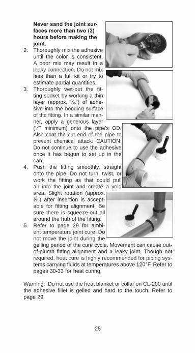
Neversandthejointsur-facesmorethantwo(2)hoursbeforemakingthejoint.
2. Thoroughly mix the adhesive until the color is consistent. A poor mix may result in a leaky connection. Do not mix less than a full kit or try to estimate partial quantities.
3. Thoroughly wet-out the fit-ting socket by working a thin layer (approx. 1⁄16") of adhe-sive into the bonding surface of the fitting. In a similar man-ner, apply a generous layer (1⁄8" minimum) onto the pipe's OD. Also coat the cut end of the pipe to prevent chemical attack. CAUTION: Do not continue to use the adhesive once it has begun to set up in the can.
4. Push the fitting smoothly, straight onto the pipe. Do not turn, twist, or work the fitting as that could pull air into the joint and create a void area. Slight rotation (approx. 1⁄2") after insertion is accept-able for fitting alignment. Be sure there is squeeze-out all around the hub of the fitting.
5. Refer to page 29 for ambi-ent temperature joint cure. Do not move the joint during the gelling period of the cure cycle. Movement can cause out-of-plumb fitting alignment and a leaky joint. Though not required, heat cure is highly recommended for piping sys-tems carrying fluids at temperatures above 120°F. Refer to pages 30-33 for heat curing.
Warning: Do not use the heat blanket or collar on CL-200 until the adhesive fillet is gelled and hard to the touch. Refer to page 29.
25

JOINTCURE
A. AmbientCureCure time is the time required for the adhesive in the assem-
bled joint to harden. Cure time depends on the type of adhesive and the ambient temperature, as shown in Table 11.
HeatAssistGel: Place an industrial hot air gun (1600 watt) approximately 6" away from the fitting and point at the socket. Continuously rotate slowly around the fitting until the bead is firm to the touch.HeatCure: We recommend heat curing all Z-CORE joints with electric heating blanket for maximum joint strength, corrosion resistance, accelerated assembly time, or if the ambient tem-perature falls below 70ºF. See pages 27-30 for Instructions for Using Heat Blankets and Collars or Bulletin No. F6640, Instructions for Using Electric Heating Collars.
26
(1) Heat cure highly recommended for piping systems carrying fluids above 120°F.(2) Times will be longer a colder temperatures and shorter at higher temperatures.NR= Not recommended.
ADHESIVE DISPOSAL: Once the adhesive and hardener have been mixed and reacted, nothing can be extracted, and it is classified as non-hazardous material. Dispose of in a nor-mal manner as other solid waste. Excess adhesive and hard-ener can be mixed, allowed to react, and disposed of as above. If extra jars of adhesive or hardener have accumulat-ed without the other component to mix and react, contact your regional manager. Hardener jars, when empty are not subject to EPA regulation and can be disposed of in a normal manner. These guide-lines are based on federal regulations. State and local regulations and ordinances should be reviewed.
TABLE11.AdhesiveAmbientCureTimeAdhesiveType
Curetime(hrs.)basedontemperature(°F)40-50 51-60 61-70 71-80 81-90 91-100
Epoxy:275 NR NR NR 24 24 24
VinylEster:CL-200(1)
CL-200QS(2)NRNR
NRNR
NR4
242
241
24NR
INSTRUCTIONSFORUSING HEAT BLANKET AND CONTROLLER
Caution: Refer to Bulletin No. 6642 for complete operating instructions• Use only with 120 volt power outlet. Special 240 volt
heat collars are available, see Bulletin No. 6640.• Blanket should not be used in wet conditions.• Tears, cuts or punctures in the blanket can create a poten-
tial safety hazard.1. Use only the proper size heat blanket for the pipe being
joined. See Table 12 on page 28.2. Wrap the blanket around the joint placing the thermis-
tor side out and the smoother side of the blanket down against the joint. Wrap around the joint until reaching the overlap. Once the blanket starts to overlap, place the tail of the blanket through the slit in the thick end of the blan-ket and pull it tight. The entire joint should be covered now and the small amount of blanket left should be laid out off of the thermistor. Now run the straps around the pipe, put them through their respective slots, and then pull tight. This will ensure a tight-fighting heat blanket providing you with the best cure.
NOTE: Check heat blanket temperature to be sure it is heating properly.3. Flange joints require heating from the inside. First, lay
the blanket flat with the thermistor down. Next, roll up the blanket from the tail so that once rolled up, the thermis-tor is facing out towards the inside of the pipe. Insert the blanket into the pipe or fitting to the depth of the adhesive joint. Leave the cord and the remaining part of the blanket exposed. The blanket may be held in position against the ID of the joint being heated by inserting a short section of smaller FRP pipe inside the rolled blanket.
4. Avoid excess flexing of the blanket. Abnormal flexing can cause breakage and shorten the service life of the blanket. DO NOT crease the heat blanket.
5. DO NOT use cleaning solvents. Solvents penetrate the rubber and damage the heating wires.
6. DO NOT carry or move the blanket by lifting it with the cord alone. Support the weight of the blanket separately from the cord to avoid abusing the cord-to-blanket connection.
Improper sizing or use of the heat blankets can cause excess heating which can damage both the piping and heat blankets.
27
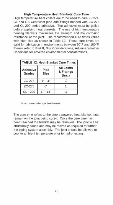
HighTemperatureHeatBlanketsCureTimeHigh temperature heat collars are to be used to cure Z-Core, CL and RB Centricast pipe and fittings bonded with ZC-275 and CL-200 series adhesive. The adhesive must be gelled before applying heat blankets. The use of high temperature heating blankets maximizes the strength and the corrosion resistance of the joint. The recommended cure times varies with pipe size as shown in Table 12. These cure times are valid for fabrication in environments between 70°F and 100°F. Please refer to Part II, Site Considerations, Adverse Weather Conditions for adverse environmental considerations.
TABLE12.HeatBlanketCureTimes
AdhesiveGrades
PipeSize
AllJoints&Fittings(hrs.)
ZC-275 1" - 4" 1⁄2
ZC-275 6" 1
CL - 200 1" - 14" ½
The cure time refers to the time a powered heat blanket must remain on the joint being cured. Once the cure time has been reached the blanket may be removed. The joint will be structurally sound and may be moved as required to further the piping system assembly. The joint should be allowed to cool to ambient temperature prior to hydro testing.
28
Based on controller style heat blanket

INSTRUCTIONSFORUSING HIGH TEMPERATURE HEAT COLLAR
RefertoBulletinNo.F6640forcompleteoperatinginstructions.
Note: Allow adhesive to gel before applying heating collar.• Do not bend or fold heating collar as this may break the
heating elements and cause the collar to work improperly or not al all.
For Pipe and Fittings:1. Use the same size heating collar as the pipe size you are
installing, with the exception of flanges. Do not use a heat-ing collar that is designed for a larger size pipe. See Table 14 on page 30.
2. With the un-insulated flap on the bottom (next to the fit-ting), carefully wrap the heating collar around the joint. Feed the strap through the square ring. CAUTION: The un-insulated flap is extremely hot when the collar is on. DO NOT TOUCH with bare hands.
3. Tighten the straps until the heating collar is snug against the joint.
For Flanges:1. For 1", 11⁄2" and 2" flanges, an industrial heat gun may be
used to cure the joint. Be sure that the end of the gun is at least six inches from the opening of the flange.
2. For 3" through 16" flange joints, use a heating collar that is one pipe size smaller than the product you are working with. Remove the straps from the heating collar.
3. Carefully turn the collar inside out with the heated area facing the I.D. of the pipe. Place the heating collar in the I.D. of the flange. A split ring of pipe may be used to hold the collar in place while the joint is curing.
For Saddles:1. Place the heating collar over the saddle outlet. During
cool weather, a wind shield is recommended to keep heat on the joint. Saddles must be heat cured for two hours.
Allow the joint to return to ambient temperature before apply-ing stress to the joint.
Note: High Temperature electric heating collars are designed to fit around fittings, and will overlap on pipe joints and cou-plings. Exceeding the recommended cure time on pipe joints where the heating collar overlaps may shorten the life of the heating collar and/or damage the pipe.The use of insulation may be necessary below 40°F to prevent heat loss.
29
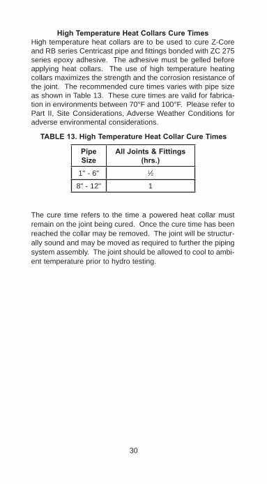
HighTemperatureHeatCollarsCureTimesHigh temperature heat collars are to be used to cure Z-Core and RB series Centricast pipe and fittings bonded with ZC 275 series epoxy adhesive. The adhesive must be gelled before applying heat collars. The use of high temperature heating collars maximizes the strength and the corrosion resistance of the joint. The recommended cure times varies with pipe size as shown in Table 13. These cure times are valid for fabrica-tion in environments between 70°F and 100°F. Please refer to Part II, Site Considerations, Adverse Weather Conditions for adverse environmental considerations.
The cure time refers to the time a powered heat collar must remain on the joint being cured. Once the cure time has been reached the collar may be removed. The joint will be structur-ally sound and may be moved as required to further the piping system assembly. The joint should be allowed to cool to ambi-ent temperature prior to hydro testing.
30
TABLE13.HighTemperatureHeatCollarCureTimes
PipeSize
AllJoints&Fittings(hrs.)
1" - 6" 1⁄2
8" - 12" 1

PARTIVBUTT&WRAPJOINTFABRICATION
Surface/EndPreparation
NOTE: It is essential to good fabrication that pipe and fitting surfaces be sanded, clean, dry, and free of oil, grease, and solvent contamination.1. Prepare both ends of the pipe, or pipe and fitting to be
joined, by sanding the bonding surfaces with 36 to 60 grit abrasive. The sanded area should extend at least 1⁄2" beyond the widest layer of glass.
EXAMPLE: 14" Pipe Size. The widest layer of fiber-
glass is 8", therefore, sand the pipe ends to a distance of 4-1⁄2" from each cut end.
2. Never sand the joint surfaces more than two (2) hours before making the joint.
3. Wipe the sanded area with a clean, dry, lint-free cloth, and avoid touching the surfaces with bare hands or dirty gloves. Do not use solvents.
InteriorSurfacePreparationFor 24" and larger piping, where accessible, use a die grinder to sand the interior sur-face of the pipe 3" from the joint ends. This will provide a proper bonding surface for applying the veil, mat, and resin to the pipe's interior surface.
SealingandSecuringThePipeEndsCoat the sawed ends of the pipe and/or fittings with catalyzed resin or Weldfast CL-200 Adhesive before join-ing the ends. Mix Weldfast CL-200 per the instructions in the Weldfast Kit. Sealing the pipe ends protects the fiberglass reinforcement from chemical attack.
31
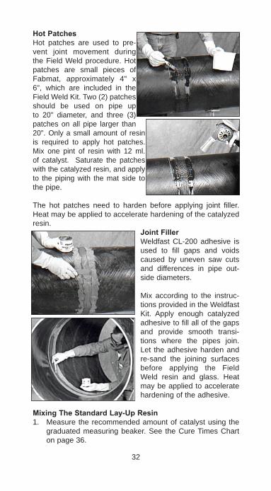
HotPatchesHot patches are used to pre-vent joint movement during the Field Weld procedure. Hot patches are small pieces of Fabmat, approximately 4" x 6", which are included in the Field Weld Kit. Two (2) patches should be used on pipe up to 20" diameter, and three (3) patches on all pipe larger than 20". Only a small amount of resin is required to apply hot patches. Mix one pint of resin with 12 ml. of catalyst. Saturate the patches with the catalyzed resin, and apply to the piping with the mat side to the pipe.
The hot patches need to harden before applying joint filler. Heat may be applied to accelerate hardening of the catalyzed resin.
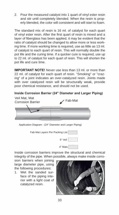
JointFillerWeldfast CL-200 adhesive is used to fill gaps and voids caused by uneven saw cuts and differences in pipe out-side diameters.
Mix according to the instruc-tions provided in the Weldfast Kit. Apply enough catalyzed adhesive to fill all of the gaps and provide smooth transi-tions where the pipes join. Let the adhesive harden and re-sand the joining surfaces before applying the Field Weld resin and glass. Heat may be applied to accelerate hardening of the adhesive.
MixingTheStandardLay-UpResin1. Measure the recommended amount of catalyst using the
graduated measuring beaker. See the Cure Times Chart on page 36.
32
2. Pour the measured catalyst into 1 quart of vinyl ester resin and stir until completely blended. When the resin is prop-erly blended, the color will consistent and will start to foam.
The standard mix of resin is 16 ml. of catalyst for each quart of vinyl ester resin. After the first quart of resin is mixed and a layer of fiberglass has been applied, it may be evident that the ratio of catalyst should be changed to allow more or less work-ing time. If more working time is required, use as little as 13 ml. of catalyst to each quart of resin. This will normally double the pot life and the curing time. If a quicker cure is required, use up to 22 ml. of catalyst for each quart of resin. This will shorten the pot life and cure time.
IMPORTANTNOTE! Never use less than 13 ml. or more than 22 ml. of catalyst for each quart of resin. "Smoking" or "craz-ing" of a joint indicates an over-catalyzed resin. Joints made with over catalyzed resin will be structurally weak, provide poor chemical resistance, and should not be used.
InsideCorrosionBarrier(24"DiameterandLargerPiping)
Inside corrosion barriers improve the structural and chemical integrity of the pipe. When possible, always make inside corro-sion barriers when joining large diameter pipe, using the following procedures:1. Wet the sanded sur-
face of the piping inte-rior with a light coat of catalyzed resin.
33
4” Mats
5” Veil
Fab-Mat Layers Per Packing List
Application Diagram - (24” Diameter and Larger Piping)
Veil Mat, MatCorrosion Barrier Fab-Mat
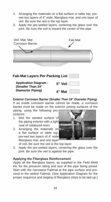
2. Arranging the materials on a flat surface or table top, pre-wet two layers of 4" wide, fiberglass mat, and one layer of veil. Be sure the veil is the top layer.
3. Apply the pre-wetted layers, centering the glass over the joint. Be sure the veil is toward the center of the pipe.
ExteriorCorrosionBarrier(SmallerThan24"DiameterPiping)If an inside corrosion barrier cannot be made, a corrosion barrier must be made on the exterior joining surfaces of the piping, using the following pro-cedures:1. Wet the sanded surface of
the piping exterior with a light coat of catalyzed resin.
2. Arranging the materials on a flat surface or table top, pre-wet two layers of 4" wide fiberglass mat, and one layer of veil. Be sure the veil is the top layer.
3. Apply the pre-wetted layers, centering the glass over the joint. Be sure the veil is against the pipe.
ApplyingtheFiberglassReinforcementApply all the fiberglass layers, as supplied in the Field Weld Kit, for the pressure rating and size of the pipe being joined. Start with the narrowest Fabmat at the pipe surface and pro-ceed to the widest Fabmat. (See Application Diagram for the proper sequence and staging of fiberglass strips to be laid-up.)
34
4” Mat
Fab-Mat Layers Per Packing List
5” VeilApplication Diagram -(Smaller Than 24”Diamerter Piping)
Veil, Mat, MatCorrosion Barrier
Fab-Mat
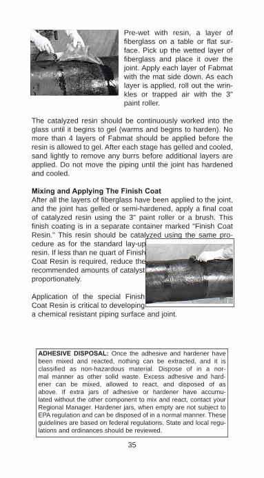
Pre-wet with resin, a layer of fiberglass on a table or flat sur-face. Pick up the wetted layer of fiberglass and place it over the joint. Apply each layer of Fabmat with the mat side down. As each layer is applied, roll out the wrin-kles or trapped air with the 3" paint roller.
The catalyzed resin should be continuously worked into the glass until it begins to gel (warms and begins to harden). No more than 4 layers of Fabmat should be applied before the resin is allowed to gel. After each stage has gelled and cooled, sand lightly to remove any burrs before additional layers are applied. Do not move the piping until the joint has hardened and cooled.
MixingandApplyingTheFinishCoatAfter all the layers of fiberglass have been applied to the joint, and the joint has gelled or semi-hardened, apply a final coat of catalyzed resin using the 3" paint roller or a brush. This finish coating is in a separate container marked "Finish Coat Resin." This resin should be catalyzed using the same pro-cedure as for the standard lay-up resin. If less than ne quart of Finish Coat Resin is required, reduce the recommended amounts of catalyst proportionately.
Application of the special Finish Coat Resin is critical to developing a chemical resistant piping surface and joint.
35
ADHESIVEDISPOSAL: Once the adhesive and hardener have been mixed and reacted, nothing can be extracted, and it is classified as non-hazardous material. Dispose of in a nor-mal manner as other solid waste. Excess adhesive and hard-ener can be mixed, allowed to react, and disposed of as above. If extra jars of adhesive or hardener have accumu-lated without the other component to mix and react, contact your Regional Manager. Hardener jars, when empty are not subject to EPA regulation and can be disposed of in a normal manner. These guidelines are based on federal regulations. State and local regu-lations and ordinances should be reviewed.

JOINTCUREThe minimum required cure time is 24 hours at 70°F. Inadequate joint strength will result if the catalyzed resin is cured at temperatures less than 60°F. Heat cure at 200°F to 275°F will accelerate cure time and increase joint strength.
Heat cure is highly recommended for piping systems carrying fluids at temperatures above 120°F. Before pressurizing the piping system, or moving the piping, cure the joint. See the Cure Times Chart below.
Note: See pages 48-50 for hydrostatic testing and system start-up procedure.
36
TABLE14.VINYLESTERBUTTWELDKITCURETIMES
Temp(°F)
PartAShelfLife(months)
PartBShelfLife(months)
PotLife(min.)
GelTime(min.)
JointCureTime(hours)
40-49 6 12 NR NR NR
50-59 5 12 NR NR NR
60-69 3-4 12 20-40 25-45 36
70-79 3-4 12 20-40 25-45 24
80-89 2-3 9 15-35 18-38 24
90-100 1-2 4 8-15 10-18 16
200-250 - - - - 2-4
PARTVINSTALLATIONCONSIDERATIONS
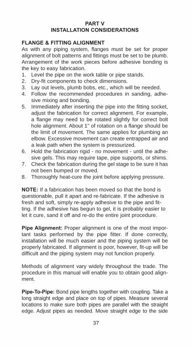
FLANGE&FITTINGALIGNMENTAs with any piping system, flanges must be set for proper alignment of bolt patterns and fittings must be set to be plumb. Arrangement of the work pieces before adhesive bonding is the key to easy fabrication.1. Level the pipe on the work table or pipe stands.2. Dry-fit components to check dimensions.3. Lay out levels, plumb bobs, etc., which will be needed.4. Follow the recommended procedures in sanding, adhe-
sive mixing and bonding.5. Immediately after inserting the pipe into the fitting socket,
adjust the fabrication for correct alignment. For example, a flange may need to be rotated slightly for correct bolt hole alignment. About 1" of rotation on a flange should be the limit of movement. The same applies for plumbing an elbow. Excessive movement can create entrapped air and a leak path when the system is pressurized.
6. Hold the fabrication rigid - no movement - until the adhe-sive gels. This may require tape, pipe supports, or shims.
7. Check the fabrication during the gel stage to be sure it has not been bumped or moved.
8. Thoroughly heat-cure the joint before applying pressure.
NOTE:If a fabrication has been moved so that the bond is questionable, pull it apart and re-fabricate. If the adhesive is fresh and soft, simply re-apply adhesive to the pipe and fit-ting. If the adhesive has begun to gel, it is probably easier to let it cure, sand it off and re-do the entire joint procedure.
PipeAlignment: Proper alignment is one of the most impor-tant tasks performed by the pipe fitter. If done correctly, installation will be much easier and the piping system will be properly fabricated. If alignment is poor, however, fit-up will be difficult and the piping system may not function properly.
Methods of alignment vary widely throughout the trade. The procedure in this manual will enable you to obtain good align-ment.
Pipe-To-Pipe:Bond pipe lengths together with coupling. Take a long straight edge and place on top of pipes. Measure several locations to make sure both pipes are parallel with the straight edge. Adjust pipes as needed. Move straight edge to the side
37
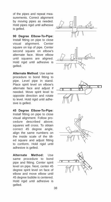
of the pipes and repeat mea-surements. Correct alignment by moving pipes as needed. Hold pipes rigid until adhesive is gelled.
90 Degree Elbow-To-Pipe:Install fitting on pipe to close visual alignment. Center square on top of pipe. Center second square on elbow's alternate face. Move elbow until squares are aligned. Hold rigid until adhesive is gelled.
AlternateMethod: Use same procedure to bond fitting to pipe. Level pipe in stand. Place spirit level on elbow's alternate face and adjust if needed. Move spirit level to opposite direction and rotate to level. Hold rigid until adhe-sive is gelled.
45 Degree Elbow-To-Pipe:Install fitting on pipe to close visual alignment. Follow pro-cedure described above; squares will cross. To obtain correct 45 degree angle, align the same numbers on the inside scale of the tilt-ed square and adjust fitting to conform. Hold rigid until adhesive is gelled.
Alternate Method: Use same procedure to bond pipe and fitting. Center spirit level on pipe. Next, center 45 degree spirit level on face of elbow and move elbow until 45 degree bubble is centered. Hold rigid until adhesive is gelled.
38

Tee-To-Pipe: Place square on tee as illustrated. Center rule on top of pipe. Blade of square should be parallel with pipe. Check by measur-ing with rule at several points along the pipe. Move square 90 degrees to side of pipe and recheck plumb by measuring with rule along side of pipe. Hold rigid until adhesive is gelled.
Flange-To-Pipe:Step 1 Level pipe in stands or vise.Step 2 Install flange on pipe to close visual alignment. Align top two holes of flange with spirit level. Move flange until bubble is centered.Step 3 Use spirit level to adjust flange face to be vertical or plumb.Step 4 Rotate assembly 90 degrees and repeat Step 3.Step 5 Hold rigid until adhesive is gelled.
AlternateMethod:Step 1 Install flange on pipe to close visual alignment. Align top two holes of flange with spirit level. Move flange until bubble is centered.Step 2 Center square on face of flange. Center rule on top of pipe. Move flange until square and pipe are parallel.Step 3 Center square on face of flange. Center rule on side of pipe and align as in Step 2.Step 4 Hold rigid until adhesive is gelled.
39
FLANGES
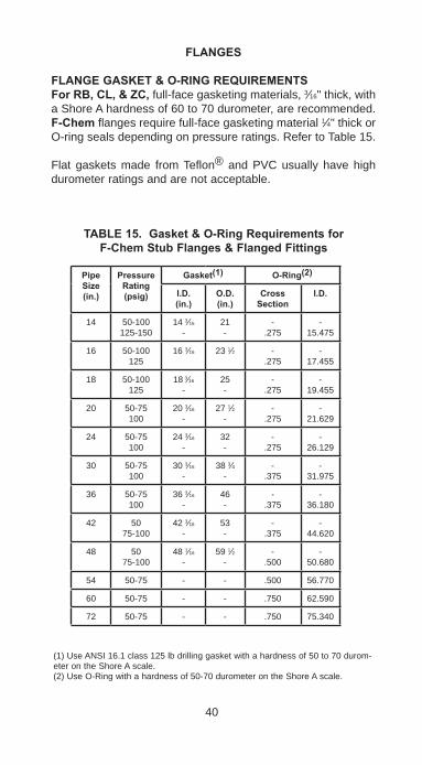
FLANGEGASKET&O-RINGREQUIREMENTSForRB,CL,&ZC, full-face gasketing materials, 3⁄16" thick, with a Shore A hardness of 60 to 70 durometer, are recommended. F-Chemflanges require full-face gasketing material 1⁄4" thick or O-ring seals depending on pressure ratings. Refer to Table 15.
Flat gaskets made from Teflon® and PVC usually have high durometer ratings and are not acceptable.
40
TABLE15.Gasket&O-RingRequirementsfor F-ChemStubFlanges&FlangedFittings
(1) Use ANSI 16.1 class 125 lb drilling gasket with a hardness of 50 to 70 durom-eter on the Shore A scale.(2) Use O-Ring with a hardness of 50-70 durometer on the Shore A scale.
PipeSize(in.)
PressureRating(psig)
Gasket(1) O-Ring(2)
I.D.(in.)
O.D.(in.)
CrossSection
I.D.
14 50-100125-150
14 3⁄16
-21-
-.275
-15.475
16 50-100125
16 3⁄16 23 1⁄2 -.275
-17.455
18 50-100125
18 3⁄16
-25-
-.275
-19.455
20 50-75100
20 3⁄16
-27 1⁄2
--
.275-
21.629
24 50-75100
24 3⁄16
-32-
-.275
-26.129
30 50-75100
30 3⁄16
-38 3⁄4
--
.375-
31.975
36 50-75100
36 3⁄16
-46-
-.375
-36.180
42 5075-100
42 3⁄16
-53-
-.375
-44.620
48 5075-100
48 1⁄16
-59 1⁄2
--
.500-
50.680
54 50-75 - - .500 56.770
60 50-75 - - .750 62.590
72 50-75 - - .750 75.340

STANDARDBOLTINGCONDITIONSFlanges meet OD, bolt circle diameter, number of holes and bolt hole diameter dimensions for ANSI B16.1, 125 lb. cast iron sizes 1"-72" and ANSI B16.5, 150 lb. steel for 1"-24" diameters.
NOTES: 1. Standard Bolt Description: Diameter - Threads per inch x Length. 2. Bolt lengths are nominal. When joining flanges to flanges of other material or manufacturers, the bolt length must be calculated.3. Use two washers with each bolt. Use SAE standard wash-
ers under all nuts and bolt heads up to 48" size. Use USS wrought washers for 54" and larger sizes.
4. Bolt torque based on National Course threads.5. ANSI B16.1, 125 lb and ANSI B16.5, 150 lb. flange dimen-
sional designs are identical for sizes 1-24".
41
TABLE16.Bolt,Washer&TorqueRequirementsfor CL,RB,ZCFlanges&FabricatedFlangedFittings
FlangeSize(in.)
No.ofBolts
MachineBoltSize
StudBoltSize
MaximumAllowableTorqueft.lbs.
Dry/Lubricated
1 4 1⁄2 -13x3 1⁄2 -13x31⁄2 10/10
1 1⁄2 4 1⁄2 -13x31⁄2 1⁄2 -13x4 20/15
2 4 5⁄8 -11x31⁄2 5⁄8 -11x41⁄2 50/35
3 4 5⁄8 -11x31⁄2 5⁄8 - 11x41⁄2 50/35
4 8 5⁄8 - 11x41⁄2 5⁄8 - 11x5 50/35
6 8 3⁄4 - 10x41⁄2 3⁄4 - 10x51⁄2 50/35
8 8 3⁄4 - 10x51⁄2 3⁄4 - 10x61⁄2 50/35
10 12 7⁄8 - 9x8 7⁄8 - 9x9 50/35
12 12 7⁄8 - 9x8 7⁄8 - 9x9 50/35
14 12 1 - 8x101⁄2 1 - 8x12 50/35
IntegralFlangedFittings
1 4 ½ - 13x3 ½ -11x31⁄2 10/10
1 ½ 4 ½ - 13x3½ ½ - 13x4 20/15
2 4 5⁄8 -11x31⁄2 5⁄8 -11x41⁄2 30/20
3 4 5⁄8 -11x31⁄2 5⁄8 -11x41⁄2 30/20
4 8 5⁄8 -11x41⁄2 5⁄8 -11x5 30/20
42
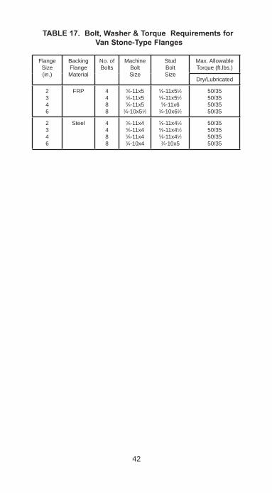
TABLE17.Bolt,Washer&TorqueRequirementsfor VanStone-TypeFlanges
FlangeSize(in.)
Backing FlangeMaterial
No. ofBolts
MachineBoltSize
StudBoltSize
Max. AllowableTorque (ft.lbs.)
Dry/Lubricated
2346
FRP 4488
5⁄8-11x55⁄8-11x55⁄8-11x5
3⁄4-10x51⁄2
5⁄8-11x51⁄25⁄8-11x51⁄2
5⁄8-11x63⁄4-10x61⁄2
50/3550/3550/3550/35
2346
Steel 4488
5⁄8-11x45⁄8-11x45⁄8-11x43⁄4-10x4
5⁄8-11x41⁄25⁄8-11x41⁄25⁄8-11x41⁄2
3⁄4-10x5
50/3550/3550/3550/35
43
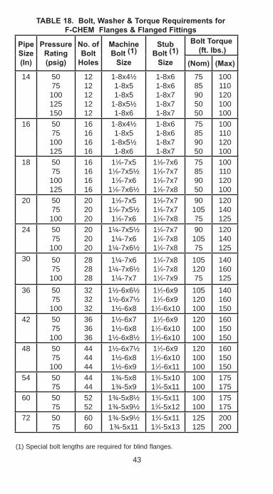
TABLE18.Bolt,Washer&TorqueRequirementsfor F-CHEMFlanges&FlangedFittings
(1) Special bolt lengths are required for blind flanges.
PipeSize(In)
PressureRating(psig)
No.ofBoltHoles
MachineBolt(1) Size
StubBolt(1) Size
BoltTorque(ft.lbs.)
(Nom) (Max)
14 5075100125150
1212121212
1-8x4½1-8x51-8x5
1-8x5½1-8x6
1-8x61-8x61-8x71-8x71-8x7
7585905050
100110120100100
16 5075100125
16161616
1-8x4½1-8x5
1-8x5½1-8x6
1-8x61-8x61-8x71-8x7
75859050
100110120100
18 5075100125
16161616
11⁄8-7x511⁄8-7x5½11⁄8-7x6
11⁄8-7x6½
11⁄8-7x611⁄8-7x711⁄8-7x711⁄8-7x8
75859050
100110120100
20 5075100
202020
11⁄8-7x511⁄8-7x5½11⁄8-7x6
11⁄8-7x711⁄8-7x711⁄8-7x8
9010575
120140125
24 5075100
202020
1¼-7x5½1¼-7x6
1¼-7x6½
11⁄4-7x711⁄4-7x811⁄4-7x8
9010575
120140125
30 5075100
282828
1¼-7x61¼-7x6½1¼-7x7
11⁄4-7x811⁄4-7x811⁄4-7x9
10512075
140160125
36 5075100
323232
1½-6x6½1½-6x7½1½-6x8
11⁄2-6x911⁄2-6x911⁄2-6x10
105120100
140160150
42 5075100
363636
1½-6x71½-6x8
1½-6x8½
11⁄2-6x911⁄2-6x10¹¹⁄2-6x10
120100100
160150150
48 5075100
444444
1½-6x7½1½-6x81½-6x9
11⁄2-6x911⁄2-6x10¹¹⁄2-6x11
120100100
160150150
54 5075
4444
1¾-5x81¾-5x9
13⁄4-5x10¹³⁄4-5x11
100100
175175
60 5075
5252
1¾-5x8½1¾-5x9½
13⁄4-5x1113⁄4-5x12
100100
175175
72 5075
6060
1¾-5x9½1¾-5x11
13⁄4-5x1113⁄4-5x13
125125
200200

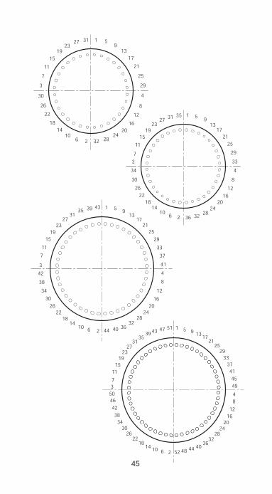
RecommendedBoltTorquingSequenceforFlanges
44
45

SPECIALFLANGEBOLTINGCONDITIONSIt is often necessary to mate flanges with other components which do not have a full flat face surface such as raised face flanges, butterfly or check valves having partial liner facings, and Van Stone flange hubs. The addition of a hard spacer ring or steel back-up ring placed between the raised face and the outer edge of the flange to form a full flat face on the mating flange is recommended. The purpose of the spacer is to fill the gap outside the raised face to prevent bolt loads from bend-ing and breaking the flange. Spacer rings are not required if a Van Stone-type flange is used when connecting to raised face flanges, valves or pumps.
46
14
5753
4945
4137
33
48
1216
2024
2832
36
2925211713951595551474339
3531
2723
19151173
5854504642
3834
30262218
10 6 2 605652484440
61
64
62
63
CONNECTINGTOOTHERPIPINGSYSTEMSIt is often necessary to connect our piping to another pip-ing system or make a connection which will not be possible using flanges. Threaded connections are offered - primarily for instruments, thermo wells, etc. Select the appropriate fit-ting from the Fittings & Accessories Bulletins. Victaulic-type grooved adapters are also available for use with Series 77 coupling in certain sizes.
ThreadedJoints1. Before making any threaded joints, be sure all bonded
joints are fully cured.2. Apply thread lubrication to both male and female threads.
A material which remains soft for the life of the joint is preferred. Be sure the thread lube is suitable for the fluid service.
3. Tighten the joint to seal. Do not over-torque. FRP threads should be handled carefully - as if they are brass.
NOTES:1. The use of adhesive to bond a steel or metal pipe into a
flange is not recommended.2. If mating our piping system to steel or other FRP system,
the preferred method is with flanges. Terminate the old system with the other FRP flange and bolt our flange on the new system.
3. Be sure to check the anchors, guides, and supports of an existing system to avoid transfer of any stresses or ther-mal expansion loads into the system.
4. Do not try to thread pipe or fittings. This is very difficult and risky. Purchase the required factory part.
TIPS: If no thread lube is available, the use of Weldfast Part "A" will usually be acceptable. Two wraps of Teflon® tape may also be used in lieu of thread lubricant.
47
Pump&EquipmentConnectionPipe connections to pumps or other equipment that involve vibration, shock loads or other mechanical movements should include flexible connectors. These flexible connectors allow for the absorption of vibration and eliminate the placing of undue strain on the pipe and fittings. A bellows-type expansion joint is recommended, although rubber hose has also been used with success.
HYDROSTATICTESTINGANDSYSTEMSTARTUPHydrostaticTesting: When possible, piping systems should be hydrostatically tested prior to being put into service. Care should be taken when testing, as in actual installation, to avoid water hammer.
All anchors, guides and supports must be in place prior to testing the line. To hydrostatically test the line, observe the following:
Water is usually introduced into the system through a one-inch diameter or smaller pipe. Provision for bleeding air from the system should be made. Water should be introduced at the lowest point in the system and the air bled off through a par-tially open valve or loose flange at all high points in the system. Slowly close the valve, and bring the system gradually up to the desired pressure.
Test pressure should not be more than 1-1⁄2 times the working pressure of the piping system, and never exceed 1-1⁄2 times the rated operating pressure of the lowest rated component in the system. When testing is completed open all of the high point air bleeds before draining the piping. This will prevent vacuum collapse of the pipe.
For systems with severe chemical or temperature applications, a cyclic test may replace the static test. Contact us for recom-mendations.
WARNINGS:AirTesting: Hydrostatic test should be used instead of air or compressed gas if possible. When air or compressed gas is used for testing, tremendous amounts of energy can be stored in the system. If a failure occurs, the energy may be released catastrophically, which can result in property damage and personal injury. In cases where system contamination or fluid weight prevents the use of hydrostatic test, air test may be used with extreme caution. To reduce the risk of air testing,
48
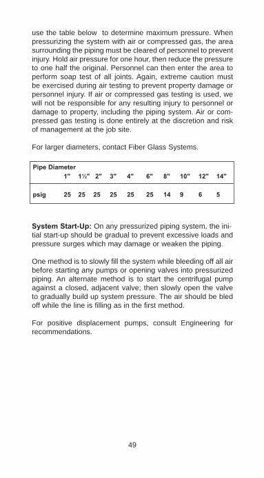
use the table below to determine maximum pressure. When pressurizing the system with air or compressed gas, the area surrounding the piping must be cleared of personnel to prevent injury. Hold air pressure for one hour, then reduce the pressure to one half the original. Personnel can then enter the area to perform soap test of all joints. Again, extreme caution must be exercised during air testing to prevent property damage or personnel injury. If air or compressed gas testing is used, we will not be responsible for any resulting injury to personnel or damage to property, including the piping system. Air or com-pressed gas testing is done entirely at the discretion and risk of management at the job site.
For larger diameters, contact Fiber Glass Systems.
SystemStart-Up: On any pressurized piping system, the ini-tial start-up should be gradual to prevent excessive loads and pressure surges which may damage or weaken the piping.
One method is to slowly fill the system while bleeding off all air before starting any pumps or opening valves into pressurized piping. An alternate method is to start the centrifugal pump against a closed, adjacent valve; then slowly open the valve to gradually build up system pressure. The air should be bled off while the line is filling as in the first method.
For positive displacement pumps, consult Engineering for recommendations.
49
PipeDiameter 1" 11⁄2" 2" 3" 4" 6" 8" 10" 12" 14"
psig 25 25 25 25 25 25 14 9 6 5
WATERHAMMER-AVOIDINGPROBLEMSWater hammer is a term generally used to describe situa-tions where a pressure surge in the piping system causes violent movement of the system. Usually this pressure surge is caused by a sudden valve closing, electrical outage, pump failure, or some other out-of-the ordinary situation. The pres-sure surge is usually brief, but damage can be severe. In FRP piping, water hammer usually results in broken fittings due to pipe system movement caused by pressure. Insufficient sys-tem anchors, guides and supports allow excessive movement of the piping and creates fitting breaks.
If you suspect water hammer, consult with the project engineer as soon as possible to eliminate the problem. This may require installing slow operating valves, a pump bypass or surge pro-tectors in the system.
More anchors, guides or supports may need to be added. If you can easily move the piping by pushing on it, changes in the pipe support arrangement to restrict movement probably need to be made.
Air in a system can also cause water hammer. Bleed air out of the piping prior to full pressure operation. Any pipe system which moves suddenly, creates a lot of noise, or generally seems unstable is a candidate for problems due to water ham-mer.
50

PARTVISYSTEMREPAIR&MODIFICATION
Should a leak occur during pressure testing or start up of the piping system, the normal procedure to repair is to cut out a fitting or a damaged section of pipe and replace it with new material.
Determine the fluid that has been in the piping system before beginning repairs to avoid contact with chemicals.
Systems often require modification, added instrumentation, or new branches. Components are available to easily accomplish this.
Always use the same pipe grade, fittings, and adhesive on new parts as is in the existing system. Do not mix pipe grades. If you have questions about the chemical service, pipe grade selection, existing system operating conditions, or other mat-ter, call your local Distributor or Regional Manager.
NOTES:1. Most leaks in a piping system are due to poor fabrication
or improper installation (i.e., not properly anchored, guided or supported).
2. When making repairs, be sure all surfaces to be bonded are dry, clean and thoroughly sanded. Good adhesive connections cannot be made on wet or contaminated sur-faces.
REPLACINGDAMAGEDPIPEPipe leaks through the pipe wall are usually the result of physical damage to the pipe from impact, vacuum, excessive bending, or other abusive conditions. The damaged section should always be replaced by using the following procedures:
Flanged Systems: If possible, replace the entire flanged length. Otherwise, cut out the damaged section and bond new flanges to the remaining pipe ends according to recommended procedures. Next, fabricate a new flange-by-flange spool to the length required. Bolt in the new pipe section.
Flanged fittings should be removed from the system when damaged and replaced with a new fitting.Attempt to find the cause of the damage and take corrective action. Solve the problem; don't just replace a part.
51

Socket/BondedSystems: Cut out the section of pipe which leaks, making sure cuts are square. Dry the pipe ends. Cut a new length of pipe to the same length as that which was cut out. Use split repair couplings to adhesive bond the new pipe into place.
1. Before fabricating connection, all seepage or fluid at the joint area must be eliminated.
2. Sand the outer surface of the pipe thoroughly for a dis-tance of at least 1" on either side of the anticipated contact area of the coupling, using 36 to 60 grit abrasive. Sand the inner and outer surface and mating edges of the inner two-piece coupling and sand the inner surface and mating edges of the outer two-piece coupling.
3. Brush away all the dust from the sanded areas taking care not to contaminate the sanded surfaces. Do not use a solvent wipe.
4. Slide the hose clamp over one of the pipe ends and out of the way of the joint area.
5. Mix the adhesive in accordance with the instructions pro-vided with the adhesive kit.
6. Coat the inner and outer surfaces and mating edges of the inner coupling with a thin layer of adhesive and set aside.
7. Coat the inner surface and mating edges of the outer cou-pling with a thin layer of adhesive and set aside.
8. Coat the cut edges of the pipe with a thin layer of adhe-sive.
9. Coat the sanded outer surfaces of the mating pipe sec-tions with a thin layer of adhesive.
10. Place the two-piece inner coupling on the pipe joint, cen-tered over the butted pipe ends.
11. Place the two-piece outer coupling over the inner coupling with the seam rotated 90 degrees away from the seam of the inner coupling.
52
12. Place the hose clamp over the center of the outer coupling and tighten.
13. Remove the excessive adhesive.14. Heat cure the adhesive in accordance with the instructions
found in the adhesive kit..
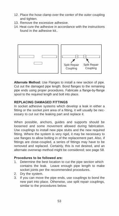
AlternateMethod: Use Flanges to install a new section of pipe. Cut out the damaged pipe length. Bond flanges to the remaining pipe ends using proper procedures. Fabricate a flange-by-flange spool to the required length and bolt into place.
REPLACINGDAMAGEDFITTINGSIn socket adhesive systems which develop a leak in either a fitting or the socket joint area of a fitting, it will usually be nec-essary to cut out the leaking part and replace it.
When possible, anchors, guides and supports should be loosened and some movement allowed during fabrication. Use couplings to install new pipe stubs and the new required fitting. Where the system is very rigid, it may be necessary to use flanges to allow bolting in of the replacement part. Also, if fittings are close-coupled, a series of fittings may have to be removed and replaced. Certainly, this is not desired, and an alternate overwrap method might be considered; see page 58.
Procedurestobefollowedare:1. Determine the best location to cut the pipe section which
contains the leak. Leave enough pipe length to make socket joints per the recommended procedures.
2. Dry the system.3. If you can move the pipe ends, use couplings to bond the
new part into place. Otherwise, use split repair couplings, similar to the procedures below.
53
Split Repair Coupling
Split Repair Coupling

AlternateMethod: If the piping arrangement does not allow the use of couplings, bond flanges to the pipe ends and bolt the replacement fitting or section into place.
54
Step 2 With Couplings
Step 2 With Split Repair Couplings
Step 2 Completed
Alternate use of Flanges
Problem Fitting
Step 1 Cut out Section
SplitRepaircoupling
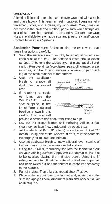
OVERWRAPA leaking fitting, pipe or joint can be over wrapped with a resin and glass lay-up. This requires resin, catalyst, fiberglass rein-forcement, tools, and a clean, dry work area. Many times an overwrap is the preferred method, particularly when fittings are in a close, complex manifold or assembly. Custom overwrap kits are available for each pipe size and pressure classification. Contact Fiber Glass Systems.
Application Procedure: Before making the over-wrap, read these instructions carefully.1. Sand the surface area thoroughly for an equal distance on
each side of the leak. The sanded surface should extent at least 1⁄2" beyond the widest layer of glass supplied with the kit. Remove all surface glazes, paint, oil, grease, scale, moisture, or other foreign material to ensure proper bond-ing of the resin material to the surface.
2. Use the applicator brush to remove all dust from the sanded area.
3. If repairing a sock-et joint, use the WELDFAST adhe-sive supplied in the kit to form a tapered bead as shown in this sketch. The bead will provide a smooth transition from fitting to pipe.
4. Lay out the precut fabmat and surfacing veil on a flat, clean, dry surface (i.e., cardboard, plywood, etc.).
5. Add contents of Part "B" tube(s) to container of Part "A" (resin). Using one of the wooden stirrers, mix the contents thoroughly for at least one minute.
6. Use the applicator brush to apply a liberal, even coating of the resin mixture to the entire sanded surface.
7. Using the 3" roller, thoroughly saturate the fabmat laid out on your working surface. Apply wet-out fabmat to the joint to be overlaid placing the mat side down. Using the 3" roller, continue to roll out the material until all entrapped air has been rolled out and the fabmat is contoured smoothly to the surface.
8. For joint sizes 4" and larger, repeat step #7 above.9. Place surfacing veil over the fabmat and, again using the
3" roller, apply a liberal amount of resin and work out all air as in step #7.
55
Socket EndVeil & Fabmat Overlay
TaperedWeldfastBead

Be sure that the pipe surface is thoroughlywet outwithcatalyzedresin.
Someguidelinesontheoverwrapare:1. The overwrap should be equally spaced on each side of
the point of the leak.2. The overwrap should be around the entire circumference
of the pipe or fitting.3. The pressure rating and pipe diameter will determine
the overwrap thickness. Consult Fiber Glass Systems' Technical Services to determine specific information about design of the overwrap.
4. The resin system of the overwrap should be compatible with the resin system of the existing pipe or fittings.
5. Cure the overwrap completely before pressure testing.
TEMPORARYFIXESPipeLeaks: The use of a conventional metal pipe clamp is a good method for containing a small leak.
SocketLeaks: Materials are available in the marketplace for making "ace bandage" types of over wraps.
FittingLeaks: A pinhole type leak can sometimes be stopped by applying a thickness of adhesive over a dry, sanded area.
CAUTION: If hazardous materials or high pressures are present, replace the damaged pipe or fitting at once. Do not try a temporary repair. Make a permanent repair as soon as possible.
TAPPINGINTOALINEThe two most common methods for adding a branch or tapping into an existing line are the use of a tee or saddle. Saddles are often rated for lower pressure than the pipe; check the rating of the system versus the saddle. Consult Fittings & Accessories Bulletins.
Generally, the use of flanges to install a new tee is preferred.
56
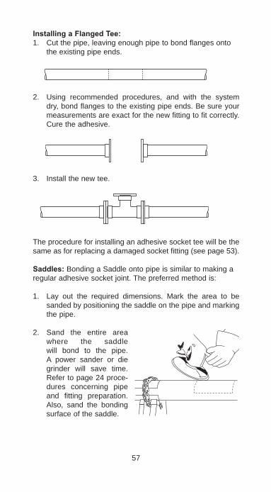
InstallingaFlangedTee:1. Cut the pipe, leaving enough pipe to bond flanges onto
the existing pipe ends.
2. Using recommended procedures, and with the system dry, bond flanges to the existing pipe ends. Be sure your measurements are exact for the new fitting to fit correctly. Cure the adhesive.
3. Install the new tee.
The procedure for installing an adhesive socket tee will be the same as for replacing a damaged socket fitting (see page 53).
Saddles: Bonding a Saddle onto pipe is similar to making aregular adhesive socket joint. The preferred method is:
1. Lay out the required dimensions. Mark the area to be sanded by positioning the saddle on the pipe and marking the pipe.
2. Sand the entire area where the saddle will bond to the pipe. A power sander or die grinder will save time. Refer to page 24 proce-dures concerning pipe and fitting preparation. Also, sand the bonding surface of the saddle.
57
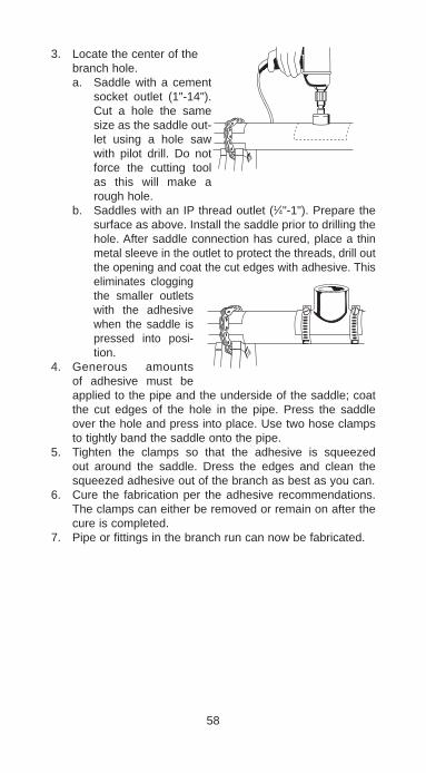
3. Locate the center of the branch hole.a. Saddle with a cement
socket outlet (1"-14"). Cut a hole the same size as the saddle out-let using a hole saw with pilot drill. Do not force the cutting tool as this will make a rough hole.
b. Saddles with an IP thread outlet (1⁄4"-1"). Prepare the surface as above. Install the saddle prior to drilling the hole. After saddle connection has cured, place a thin metal sleeve in the outlet to protect the threads, drill out the opening and coat the cut edges with adhesive. This eliminates clogging the smaller outlets with the adhesive when the saddle is pressed into posi-tion.
4. Generous amounts of adhesive must be applied to the pipe and the underside of the saddle; coat the cut edges of the hole in the pipe. Press the saddle over the hole and press into place. Use two hose clamps to tightly band the saddle onto the pipe.
5. Tighten the clamps so that the adhesive is squeezed out around the saddle. Dress the edges and clean the squeezed adhesive out of the branch as best as you can.
6. Cure the fabrication per the adhesive recommendations. The clamps can either be removed or remain on after the cure is completed.
7. Pipe or fittings in the branch run can now be fabricated.
58

Centigrade Fahrenheit Centigrade Fahrenheit
PARTVIIHELPFULINFORMATION
59
-200 -328.0 -100 -148.0 -90 -130.0 -80 -112.0 -70 -94.0 -60 -76.0 -50 -58.0 -40 -40.0 -30 -22.0 -20 -4.0 -10 14.0 0 32.0 1 33.8 2 35.6 3 37.4 4 39.2 5 41.0 6 42.8 7 44.6 8 46.4 9 48.2 10 50.0 11 51.8 12 53.6 13 55.4 14 57.2 15 59.0 16 60.8 17 62.6 18 64.4 19 66.2 20 68.0 21 69.8 22 71.6 23 73.4
24 75.2 25 77.0 26 78.8 27 80.6 28 82.4 29 84.2 30 86.0 31 87.8 32 89.6 33 91.4 34 93.2 35 95.0 36 96.8 37 98.6 38 100.4 39 102.2 40 104.0 41 105.8 42 107.6 43 109.4 44 111.2 45 113.0 46 114.8 47 116.6 48 118.4 49 120.2 50 122.0 51 123.8 52 125.6 53 127.4 54 129.2 55 131.0 56 132.8 57 134.6 58 136.4
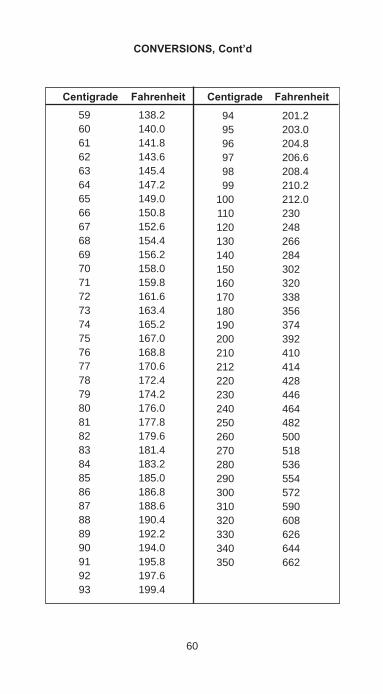
60
Centigrade Fahrenheit Centigrade Fahrenheit
CONVERSIONS,Cont’d
59 138.2 60 140.0 61 141.8 62 143.6 63 145.4 64 147.2 65 149.0 66 150.8 67 152.6 68 154.4 69 156.2 70 158.0 71 159.8 72 161.6 73 163.4 74 165.2 75 167.0 76 168.8 77 170.6 78 172.4 79 174.2 80 176.0 81 177.8 82 179.6 83 181.4 84 183.2 85 185.0 86 186.8 87 188.6 88 190.4 89 192.2 90 194.0 91 195.8 92 197.6 93 199.4
94 201.2 95 203.0 96 204.8 97 206.6 98 208.4 99 210.2 100 212.0 110 230 120 248 130 266 140 284 150 302 160 320 170 338 180 356 190 374 200 392 210 410 212 414 220 428 230 446 240 464 250 482 260 500 270 518 280 536 290 554 300 572 310 590 320 608 330 626 340 644 350 662

61
MetricUnits U.S.EquivalentsLengths 1 millimeter . . . . . . . . . . .0.03937 inch 1 centimeter . . . . . . . . . . .0.3937 inch 1 meter . . . . . . . . . . . . . .39.37 inches or 1.094 yards 1 kilometer . . . . . . . . . . . .1093.61 yards or 0.6214 mileAreas 1 square millimeter . . . . .0.00155 square inch 1 square centimeter . . . . .0.155 square inch 1 square meter . . . . . . . .10.764 square feet or 1.196 sq. yards 1 square kilometer . . . . . .0.3861 square mileVolumes 1 cubic millimeter . . . . . .0.000061 cubic inch 1 cubic centimeter . . . . . .0.061 cubic inch 1 liter . . . . . . . . . . . . . . . .61.025 cubic inches 1 cubic meter . . . . . . . . . .35.314 cubic feet or 1.3079 cubic yardsCapacities 1 milliliter (0.001 liter) . . .0.0338 U.S. fluid ounce 1 liter . . . . . . . . . . . . . . . .2.1134 U.S. liquid pints 1 liter . . . . . . . . . . . . . . . .1.0567 U.S. liquid quarts 1 liter. . . . . . . . . . . . . . . . .0.2642 U.S. gallon
Weights 1 gram . . . . . . . . . . . . . . .0.03527 avoir. ounce or 15.4324 grains 1 kilogram(1000 grams) 2.2046 avoir. pounds
U.S.SystemUnits MetricEquivalentsLengths 1 inch 25.4 millimeters or 2.54 centimeters 1 foot . . . . . . . . . . . . 0.3048 meter 1 yard . . . . . . . . . . . 0.9144 meter 1 mile . . . . . . . . . . . . 1.6093 kilometersAreas 1 square inch . . . . . . 645.16 square millimeters or 6.452 square centimeters 1 square foot . . . . . . 0.0929 square meter 1 square yard . . . . . 0.8361 square meter 1 square mile . . . . . . 2.59 square kilometersVolumes 1 cubic inch . . . . . . . 16,387.2 cubic millimeters or 16.3872 cubic centimeters 1 cubic foot . . . . . . . . 0.02832 cubic meter 1 cubic yard . . . . . . . 0.7646 cubic meter Capacities 1 U.S. fluid ounce . . 29.573 milliliters 1 U.S. liquid pint . . . 0.47317 liter 1 U.S. liquid quart . . 0.94633 liter 1 U.S. gallon . . . . . . 3.78533 litersWeights 1 grain . . . . . . . . . . . 0.0648 gram 1 avoir. ounce. . . . . . 28.35 grams 1 avoir. pound . . . . . 0.4536 kilogram 1 Troy ounce . . . . . . 31.1035 grams
CONVERSIONS,Cont’d

62
Inches DecimalofanInch Inches DecimalofanInch
DECIMALEQUIVALENTSOFFRACTIONS
1⁄64 .015625 1⁄32 .03125 3⁄64 .046875 1⁄20 .05 1⁄16 .0625 1⁄13 .0769 5⁄64 .078125 1⁄12 .0833 1⁄11 .0909 3⁄32 .09375 1⁄10 .10 7⁄64 .109375 1⁄9 .111 1⁄8 .125 9⁄64 .140625 1⁄7 .1429 5⁄32 .15625 1⁄6 .1667 11⁄64 .171875 3⁄16 .1875 1⁄5 .2 13⁄64 .203125 7⁄32 .21875 15⁄64 .234375 1⁄4 .25 17⁄64 .265625 9⁄32 .28125 19⁄64 .296875 5⁄16 .3125 21⁄64 .328125 1⁄3 .333 11⁄32 .34375 23⁄64 .359375 3⁄8 .375 25⁄64 .390625 13⁄32 .40625 7⁄16 .4375
29⁄64 .453125 15⁄32 .46875 31⁄64 .484375 1⁄2 .5 33⁄64 .515625 17⁄32 .53125 35⁄64 .546875 9⁄16 .5625 37⁄64 .578125 19⁄32 .59375 39⁄64 .609375 5⁄8 .625 41⁄64 .640625 21⁄32 .65625 43⁄64 .671875 11⁄16 .6875 45⁄64 .703125 23⁄32 .71875 47⁄64 .734375 3⁄4 .75 49⁄64 .765625 25⁄32 .78125 51⁄64 .796875 13⁄16 .8125 53⁄64 .828125 27⁄32 .84375 55⁄64 .859375 7⁄8 .875 57⁄64 .890625 29⁄32 .90625 59⁄64 .921875 15⁄16 .9375 61⁄64 .953125 31⁄32 .96875 63⁄64 .984375 1 1.0
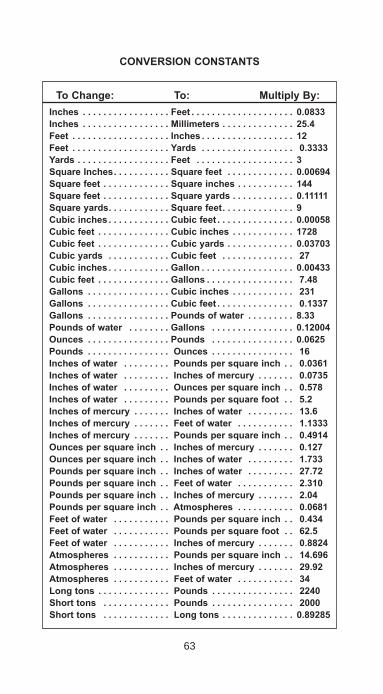
63
CONVERSIONCONSTANTS
ToChange: To: MultiplyBy:Inches . . . . . . . . . . . . . . . . . Feet . . . . . . . . . . . . . . . . . . . . 0.0833Inches . . . . . . . . . . . . . . . . . Millimeters. . . . . . . . . . . . . . 25.4Feet . . . . . . . . . . . . . . . . . . . Inches . . . . . . . . . . . . . . . . . . 12Feet . . . . . . . . . . . . . . . . . . . Yards. . . . . . . . . . . . . . . . . . 0.3333Yards. . . . . . . . . . . . . . . . . . Feet . . . . . . . . . . . . . . . . . . . 3SquareInches. . . . . . . . . . . Squarefeet. . . . . . . . . . . . . 0.00694Squarefeet. . . . . . . . . . . . . Squareinches. . . . . . . . . . . 144Squarefeet. . . . . . . . . . . . . Squareyards. . . . . . . . . . . . 0.11111Squareyards. . . . . . . . . . . . Squarefeet. . . . . . . . . . . . . . 9Cubicinches . . . . . . . . . . . . Cubicfeet . . . . . . . . . . . . . . . 0.00058Cubicfeet . . . . . . . . . . . . . . Cubicinches . . . . . . . . . . . . 1728Cubicfeet . . . . . . . . . . . . . . Cubicyards. . . . . . . . . . . . . 0.03703Cubicyards. . . . . . . . . . . . Cubicfeet . . . . . . . . . . . . . . 27Cubicinches . . . . . . . . . . . . Gallon . . . . . . . . . . . . . . . . . . 0.00433Cubicfeet . . . . . . . . . . . . . . Gallons . . . . . . . . . . . . . . . . . 7.48Gallons . . . . . . . . . . . . . . . . Cubicinches . . . . . . . . . . . . 231Gallons . . . . . . . . . . . . . . . . Cubicfeet . . . . . . . . . . . . . . . 0.1337Gallons . . . . . . . . . . . . . . . . Poundsofwater . . . . . . . . . 8.33Poundsofwater . . . . . . . . Gallons . . . . . . . . . . . . . . . . 0.12004Ounces . . . . . . . . . . . . . . . . Pounds . . . . . . . . . . . . . . . . 0.0625Pounds . . . . . . . . . . . . . . . . Ounces . . . . . . . . . . . . . . . . 16Inchesofwater . . . . . . . . . Poundspersquareinch . . 0.0361Inchesofwater . . . . . . . . . Inchesofmercury . . . . . . . 0.0735Inchesofwater . . . . . . . . . Ouncespersquareinch . . 0.578Inchesofwater . . . . . . . . . Poundspersquarefoot. . 5.2Inchesofmercury . . . . . . . Inchesofwater . . . . . . . . . 13.6Inchesofmercury . . . . . . . Feetofwater . . . . . . . . . . . 1.1333Inchesofmercury . . . . . . . Poundspersquareinch . . 0.4914Ouncespersquareinch . . Inchesofmercury . . . . . . . 0.127Ouncespersquareinch . . Inchesofwater . . . . . . . . . 1.733Poundspersquareinch . . Inchesofwater . . . . . . . . . 27.72Poundspersquareinch . . Feetofwater . . . . . . . . . . . 2.310Poundspersquareinch . . Inchesofmercury . . . . . . . 2.04Poundspersquareinch . . Atmospheres . . . . . . . . . . . 0.0681Feetofwater . . . . . . . . . . . Poundspersquareinch . . 0.434Feetofwater . . . . . . . . . . . Poundspersquarefoot. . 62.5Feetofwater . . . . . . . . . . . Inchesofmercury . . . . . . . 0.8824Atmospheres . . . . . . . . . . . Poundspersquareinch . . 14.696Atmospheres . . . . . . . . . . . Inchesofmercury . . . . . . . 29.92Atmospheres . . . . . . . . . . . Feetofwater . . . . . . . . . . . 34Longtons . . . . . . . . . . . . . . Pounds . . . . . . . . . . . . . . . . 2240Shorttons . . . . . . . . . . . . . Pounds . . . . . . . . . . . . . . . . 2000Shorttons . . . . . . . . . . . . . Longtons. . . . . . . . . . . . . . 0.89285
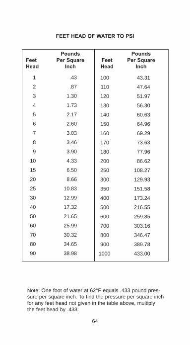
64
Pounds Pounds Feet PerSquare Feet PerSquare Head Inch Head Inch
FEETHEADOFWATERTOPSI
1 .43
2 .87
3 1.30
4 1.73
5 2.17
6 2.60
7 3.03
8 3.46
9 3.90
10 4.33
15 6.50
20 8.66
25 10.83
30 12.99
40 17.32
50 21.65
60 25.99
70 30.32
80 34.65
90 38.98
100 43.31
110 47.64
120 51.97
130 56.30
140 60.63
150 64.96
160 69.29
170 73.63
180 77.96
200 86.62
250 108.27
300 129.93
350 151.58
400 173.24
500 216.55
600 259.85
700 303.16
800 346.47
900 389.78
1000 433.00
Note: One foot of water at 62°F equals .433 pound pres-sure per square inch. To find the pressure per square inch for any feet head not given in the table above, multiply the feet head by .433.
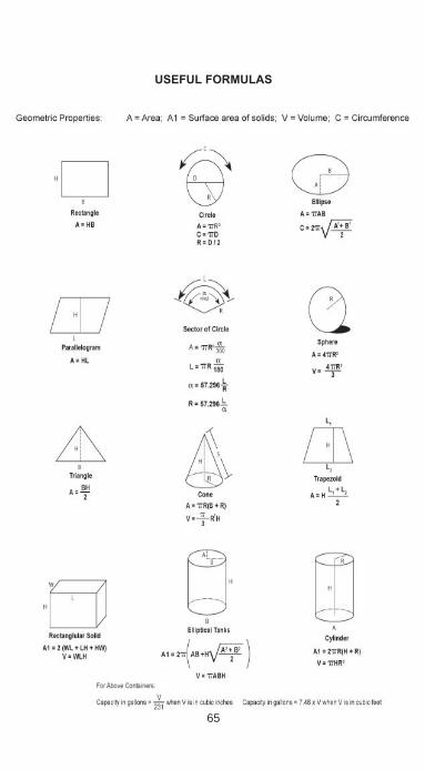
65
USEFULFORMULAS
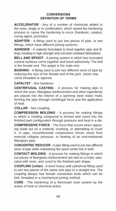
CONVERSIONSDEFINITIONOFTERMS
ACCELERATOR - Any of a number of chemicals added to the resin, singly or in combination, which speed the hardening process or cause the hardening to occur (hardener, catalyst, curing agent, promoter).ADAPTER - A fitting used to join two pieces of pipe, or two fittings, which have different joining systems.ADHESIVE - A material formulated to bond together pipe and fit-tings resulting in high strength and corrosion resistant fabrications.BELLANDSPIGOT - A joining system in which two truncated conical surfaces come together and bond adhesively. The bell is the female end. The spigot is the male end.BUSHING - A fitting used to join two different sizes of pipe byreducing the size of the female end of the joint. Joints may come threaded or tapered.CATALYST - See hardener.CENTRIFUGAL CASTING - A process for making pipe in which the resin, fiberglass reinforcement and other ingredients are placed into the interior of a spinning steel rotary mold, forming the pipe through centrifugal force and the application of heat.COLLAR - See coupling.COMPRESSION MOLDING - A process for making fittings in which a molding compound is formed and cured into the finished part configuration through pressure and heat in a die.COMPRESSIVEFORCE - The force that occurs when oppos-ing loads act on a material, crushing, or attempting to crush it. In pipe, circumferential compressive forces result from external collapse pressure, or heating of an end-restrained fiberglass pipe.CONCENTRICREDUCER - A pipe fitting used to join two different sizes of pipe while maintaining the same center line in both.CONTACTMOLDING - A process for making fittings in which cut pieces of fiberglass reinforcement are laid on a mold, satu-rated with resin, and cured to the finished part shape.COUPLING(collar) - A short heavy wall cylindrical fitting used to join two pieces of the same size pipe in a straight line. The coupling always has female connection ends which can be bell, threaded or a mechanical joining method.CURE - The hardening of a thermoset resin system by the action of heat or chemical action.
66

CURE STAGES - Stages describe the degree to which a thermoset resin has crosslinked. Three stages, in order of increasing cross linking, include B-stage, gelled, fully cured.CURETIME - The time required for a thermoset material to react and develop full strength and material properties. The time is dependent upon the temperature of the material.CURINGAGENT - See hardener.CUTAND MITERED FITTINGS - Fittings manufactured by cutting, assembling and bonding pipe sections into a desired configuration. The assembled product is then over wrapped with resin-impregnated roving or glass cloth, to provide added strength.EPOXY RESIN - A thermosetting resin, usually made from Bisphenol A and epichlorhydrin, cured by a variety of agents such as anhydrides and amines. These resins contain cyclic ether groups. See thermoset.FRP - Fiberglass Reinforced Plastic.FABMAT - A combination of woven roving and chopped strand mat held together with resin binders. Usually used for making contact molded fittings and butt weld joints.FILAMENTWOUND - A manufacturing method for pipe and fittings in which resin impregnated continuous strand roving wraps around a mandrel to achieve high reinforcement con-centration and precise filament placement.FILLERS(extender,pigments,inerts;i.e.,sand,etc.) -Materials added to a resin which do not affect the cure of the resin but may influence the physical properties of the resin system.FITTINGTYPES – The classification of fittings by the method of manufacture; i.e., molded, cut and mitered, filament wound, contact molded.GELTIME– The time it takes for a resin system to harden to a rubber-like state.HANDLAY-UP – Any number of methods of forming resin and fiberglass into finished pipe products by manual procedures. Hand lay-up products do not usually exhibit optimum strength of the reinforcing material since the fibers do not lie oriented for maximum performance. These procedures include over-wrap techniques, contact molding, hand molding and others.HARDENER (accelerator, catalyst, curing agent, promoter) –Any of a number of chemicals added to the resin, single or in combination, which speed up the hardening process, or cause hardening to occur.
67
HEATBLANKET or HEATCOLLAR – An electrical device used to heat a fabrication to reduce cure time.HYDROSTATICTEST – A pressure test of the completed fab-rication to confirm good quality. Typically, the system is filled with water and held at the selected pressure while checking for leaks.IMPACTRESISTANCE – The ability of a part to absorb a strik-ing blow without damage.JOINING(connectingsystems) – Any of a variety of meth-ods for connecting two separate components of a piping system together. Included are bell and spigot, threaded and coupled, mechanical devices, etc.JOINT – A term used to describe an individual length of pipe or the actual joining mechanism; i.e., adhesive bonded bell and spigot, threaded and coupled, etc.)LINER – A generic term used to describe the interior surface in pipe. Generally, liners are resin-rich regions from 0.005 to 0.100 in. thick. Liners may be reinforced with fibrous material such as veil or mat. Liners can provide extra corrosion protec-tion for severe chemical service. They also form a leak barrier (elastomer bladder). The manufacturer may add a liner before, during, or after construction of the pipe wall depending on the manufacturing process.MATRIX - The material used to bind reinforcement and fillers together. This material may be thermoplastic or thermosetting and dictates to a large extent the temperature and chemical service conditions allowable for a pipe or fitting.MOLDED FITTINGS - Pipe fittings formed of compressing resin, chopped fiber and other ingredients in a mold under heat and pressure.MOLDING - Any of several manufacturing methods where pressure or compression molding shapes resin and reinforcing materials into final products.OVERWRAP - A method of repair or joining in which fiberglass reinforcement and resin are fabricated over the selected area.POLYESTERRESIN - Any of a large family of resins which are normally cured by cross linking with styrene. The physical and chemical properties of polyester resins vary greatly. Some have excellent chemical and physical properties while others do not. Vinyl esters are a specific type of polyester resin. Other polyester resins with properties suitable for use in the manufacture of fiberglass pipe include: isophthalic Bisphenol A fumarate and HET acid polyesters. Each type of resin has particular strengths and weaknesses for a given piping appli-cation.
68
POTLIFE - The time available to use thermoset adhesives after the reactive materials have been mixed.PRESSURERATING - The maximum anticipated long-term operating pressure a manufacturer recommends for a given product. Also referred to as working pressure, class or design pressure.PROMOTER - See hardener.REINFORCEMENT - Typically, fibers of glass, carbon or syn-thetic material used to provide strength and stiffness to a com-posite material. The type of fiber used as reinforcement play a major role in determining the properties of a composite, as does the fiber diameter and the type of sizing used. Terms relating to the physical form of the reinforcement include:
ChoppedFiber - Continuous fibers cut into short (0.125 to 2.0-in.) lengths.Filament - A single fiber of glass; e.g., a mono filament.Mats- Coarse fabric sheets made from chopped strands randomly placed and held together by resin binders.MilledFibers - Glass fibers, ground or milled, into short (0.032 to 0.125-in.) lengths.Roving - A collection of one or more strands wound into a cylindrical package. The typical form of glass fiber used in the manufacture of filament wound pipe.Veil - Surfacing mat of porous fabric made from filaments. Used to provide a resin rich layer or liner.Yarn - Glass fiber filaments twisted together to form textile-type fibers.Yield - The number of yards of material made from one pound of the product.Resin (polymer) - As applied to fiberglass pipe, resin is the polymer or plastic material used to bind the glass fibers together.
RESIN - The polymer (liquid plastic) material which hardens with cure to provide a solid form, holding the fiberglass rein-forcement in place. Resins provide the corrosion resistance in FRP parts.SADDLE - A fitting which is bonded to the exterior of a pipe to make a branch connection.SHELFLIFE - The storage time for a material until it becomes unusable.SOCKETJOINT- A joining system in which two straight cylin-drical surfaces come together and bond adhesively.
69
STRESS - The force per unit of cross sectional area. Measured in pounds per square inch (psi). This should not be confused with hydraulic pressures, measured as psig or psia, which can induce stress.SUPPORTSPACING(span) - The recommended maximumdistance between pipe supports to prevent excessive pipedeformation (bending).SURGEPRESSURE - A transient pressure increase due to rapid changes in the momentum of flowing fluids. Water ham-mer is one type of surge pressure. Rapid opening or closing of valves often result in a surge pressure or water hammer.THERMAL CONDUCTIVITY - The rate at which a material (pipe) transmits heat from an area of high temperature to an area of lower temperature. Fiberglass pipe has low thermal conductivity.THERMAL EXPANSION - The increase in dimensions of a material (pipe) resulting from an increase in temperature. A decrease in temperature results in thermal contraction.THERMOSET - A polymeric resin cured by heat or chemical additives. Once cured, a thermoset resin becomes essentially infusible, (cannot be re-melted) and insoluble. Thermosetting resins used in pipe generally incorporate reinforcements. Typical thermosets include:• Vinyl esters • Novolac or epoxy Novolac• Epoxies • Unsaturated polyestersTHRUSTFORCES - Commonly used to describe the forces resultant from changes in direction of a moving column of fluid. Also used to describe the axial or longitudinal end loads at fit-tings, valves, etc., resultant from hydraulic pressure.TORQUE - Used to quantify a twisting force (torsion) in pipe. Torque is measured as a force times the distance from the force to the axis of rotation. Torque is expressed in foot-pounds (ft-lb) or inch-pounds (in-lb).TWOHOLING - A method of aligning flanges onto pipe or fit-tings so that the bolt circle will mate with the adjoining flange.VINYLESTER - A premium resin system with excellent corro-sion resistance. Vinyl ester exhibits high versatility, tempera-ture resistance and excellent corrosion resistance to acids.WATER HAMMER - Pressure surges in a piping system caused by sudden operation of a valve, pump, or other com-ponent.
70

71
HOWTOREADFLANGEDORREDUCINGFITTINGS
The above sequence should be used when describ-ing fitting outlets. Drawings or sketches showing outlet types, locations, sizes and dimensional requirements are required for more complicated fitting configurations.
TEE
Run x Run x Branch
LATERALRun x Run x Branch
CROSSRun x Run x Branch X Branch
(AxBxC)
(AxBxC)
(AxBxCxD)

72
HOWTOFIGUREA45°OFFSET
OffsetLength
OffsetLength
TrueLength
45°
True Length = offset x 1.414Offset = true length x .707
EXAMPLES:offset = 12"
12" x 1.414 = 16.968 = 1'-5"true length = 1'-5"(to nearest 1⁄16")true length = 24"
24 x .707 = 16.968 = 1'-5"offset length = 1'-5"
(to nearest 1⁄16")

73

74
www.fgspipe.com
2700 West 65th Street 25 S. Main StreetLittle Rock, Arkansas 72209 Sand Springs, Oklahoma 74063Phone: 1 (501) 618-2256 1 (918) 245-6651
©2011, NATIONAL OILWELL VARCO®Trademark of NATIONAL OILWELL VARCO
F6080 - July 2011

![One platform Multiple options...GOST Butt weld DIN Butt weld ANSI Butt weld Socket weld Female 1 pipe thread F-con. ) butt weld GOST Butt weld [mm] [in.] D A SOC FTP F G D A SOC FTP](https://img.pdfslide.us/doc/110x75/5fe23d7adfe1ef18be65fa23/one-platform-multiple-options-gost-butt-weld-din-butt-weld-ansi-butt-weld-socket.jpg)