Embed Size (px)
Citation preview
PIPE INSPECTION AND REPAIR
Larry Ritchie
February 23, 2010
PIPE INSPECTION AND REPAIRPIPE INSPECTION AND REPAIR
The Florida Department of TransportationThe Florida Department of Transportation builds and maintains hundreds of miles of underground infrastructure as part of its transportation system.
Building, repairing and maintaining drainage systems is expensive and must be done correctly to ensure the expected service life and mitigate any future problems.
PIPE INSPECTION AND REPAIR
Over the last 5 years, the Department hasOver the last 5 years, the Department has spent approximately 175 million dollars on drainage pipe and over 9.5 million dollars on pipe repair.
With costs like these, it is extremely important to ensure that pipe is installed correctly, inspected thoroughly and replaced or repaired correctly when warranted.
PIPE INSPECTION AND REPAIR
The purpose of this presentation is to:
Discuss the Standard Specifications for drainage p ginstallation and inspection requirements.
Review some of the common issues associated with pipe installation.
Highlight acceptable repair materials and g g p pmethods found in the Pipe Repair Matrix.
Discuss the future of pipe inspection and repair.Discuss the future of pipe inspection and repair.
DRAINAGE INSTALLATIONDRAINAGE INSTALLATION
All work on FDOT projects is governed by the Standard Specifications found in the contract documents.
Drainage installation is covered in at least two separate sections – Section 5 and Section 430 pof the Standard Specifications.
DRAINAGE INSTALLATIONDRAINAGE INSTALLATIONSection 5 – Control of Work – describes some of h l d l d hthe general guidelines associated with project construction.
Section 5‐3 – Conformity of Work with Contract Documents states the contractor will “performDocuments – states the contractor will perform all work and furnish all materials in reasonably close conformity with the lines, grades, cross y , g ,sections, dimensions, and material requirements, including tolerances, as specified in the Contract D ”Documents.”
DRAINAGE INSTALLATIONDRAINAGE INSTALLATION
Section 430 – Pipe Culverts – Lists all of theSection 430 Pipe Culverts Lists all of the tolerances and construction requirements for furnishing and installing drainage pipe and end g g g p psections at locations called for in the plans.
Acceptable pipe materials
Directions for laying pipey g p p
Final Inspection requirements
Specific requirements for each pipe typep q p p yp
DRAINAGE INSTALLATIONDRAINAGE INSTALLATION
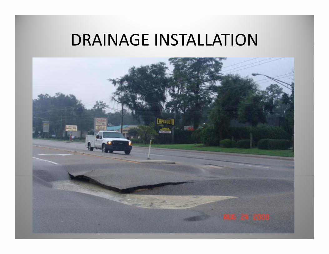
These Specifications are in place to help ensure the Department receives qualityensure the Department receives quality materials and workmanship on all FDOT construction projects and to help preventconstruction projects and to help prevent…..
DRAINAGE INSTALLATION
FINAL PIPE INSPECTIONFINAL PIPE INSPECTION
Allows the contractor and the Department toAllows the contractor and the Department to obtain a first hand account of the condition of culvert pipe installed on a constructionculvert pipe installed on a construction project.
Provides the Department with some h h d iassurance that the drainage system was
installed correctly and is functioning properly.
WHEN TO INSPECTWHEN TO INSPECT
Section 430‐4.8 states that “upon completionSection 430 4.8 states that upon completion of placement of concrete pavement or the placement of structural asphalt, but prior to the placement of the asphalt friction course, dewater installed pipe and provide the E i i h id di h d lEngineer with a video recording schedule allowing for pipe videoing and reports to be completed and submitted to the Departmentcompleted and submitted to the Department and reviewed prior to the continuation of pavement ”pavement.
FINAL PIPE INSPECTIONFINAL PIPE INSPECTION
The Department encourages contractors to e epa t e t e cou ages co t acto s toperform inspections on their culverts and storm sewers as soon as possible to discover and
bl h d dmitigate any problems that occurred during installation.
However, a contractor is required to submit their video report to the Department uponvideo report to the Department upon completion of concrete pavement or placement of structural asphalt.p
FINAL PIPE INSPECTIONFINAL PIPE INSPECTION
Video inspection prior to placement of the p p pfriction course allows the contractor to discover and mitigate any problems with pipe installation with fewer obstacles. This saves everyone time, money and headaches!
FINAL PIPE INSPECTIONFINAL PIPE INSPECTION
Overall the quality of the video inspectionOverall, the quality of the video inspection documentation has improved. However, there are still several areas of concern:are still several areas of concern:
1. Camera Speed during the video inspectionp g p
2. Partial inspection or completely missed joints
3. Only inspecting joints and not evaluating the entire pipepipe

CAMERA SPEEDMove the camera through the pipe at a speed no greater than 30 feet per minutegreater than 30 feet per minute.
JOINT INSPECTIONFilm the entire circumference at each joint.
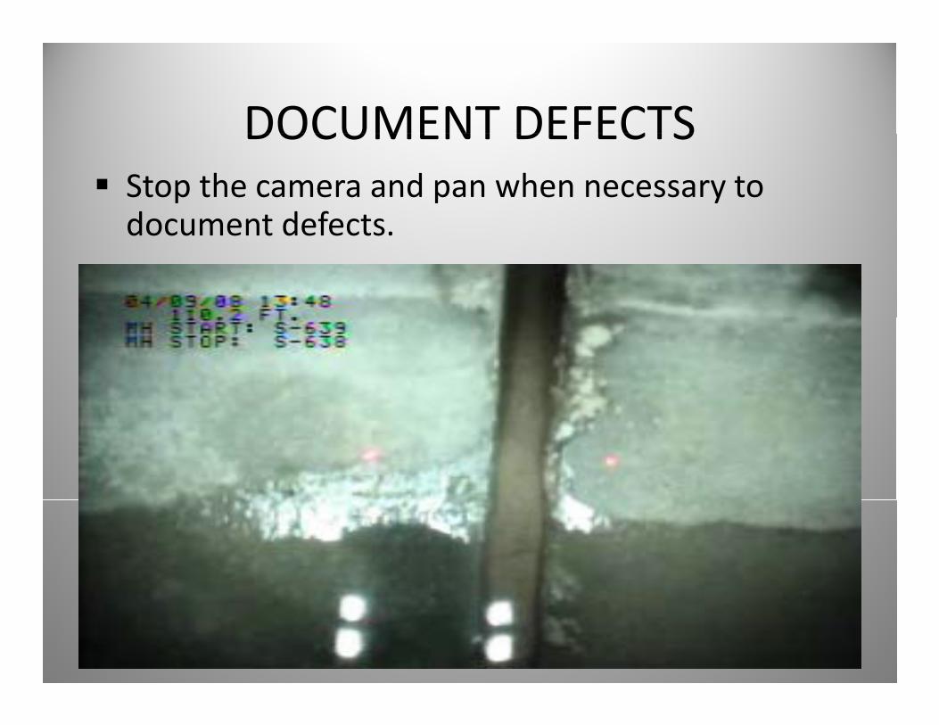
DOCUMENT DEFECTSDOCUMENT DEFECTSStop the camera and pan when necessary to document defectsdocument defects.
FINAL PIPE INSPECTIONFINAL PIPE INSPECTION
It is important to remember that the videoIt is important to remember that the video report is in fact part of the Specifications and can be rejected if it is not performedcan be rejected if it is not performed according to Section 430.
Make sure your pipe inspector is familiar with h l i S i 430 4 8 h bthe language in Section 430‐4.8 or he may be performing this service more than once!
Common Pipe Issues Seen During Inspection
Over the past year, the majority of pipe issues reviewed and repaired have been:
Leaking Jointsg
Joint Gaps
DeflectionDeflection
Cracking
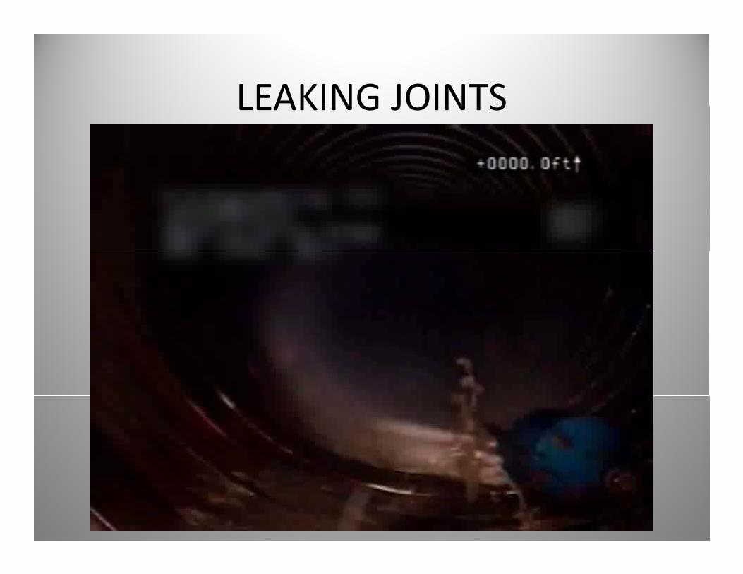
LEAKING JOINTSLEAKING JOINTS
LEAKING JOINTSLEAKING JOINTS
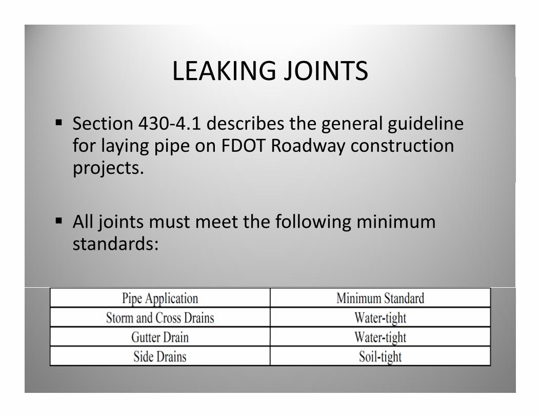
Section 430‐4.1 describes the general guideline Sect o 30 . desc bes t e ge e a gu de efor laying pipe on FDOT Roadway construction projects.
All joints must meet the following minimum standards:
LEAKING JOINTSLEAKING JOINTS
Soil‐tight joints must be water‐tight to 2 psiSoil tight joints must be water tight to 2 psi.
i h j i b i h iWater‐tight joints must be water‐tight to 5 psi unless a higher pressure rating is required in h lthe plans.
Leaking joints occur in both flexible and rigid pipe types.p p yp
LEAKING JOINTSLEAKING JOINTS
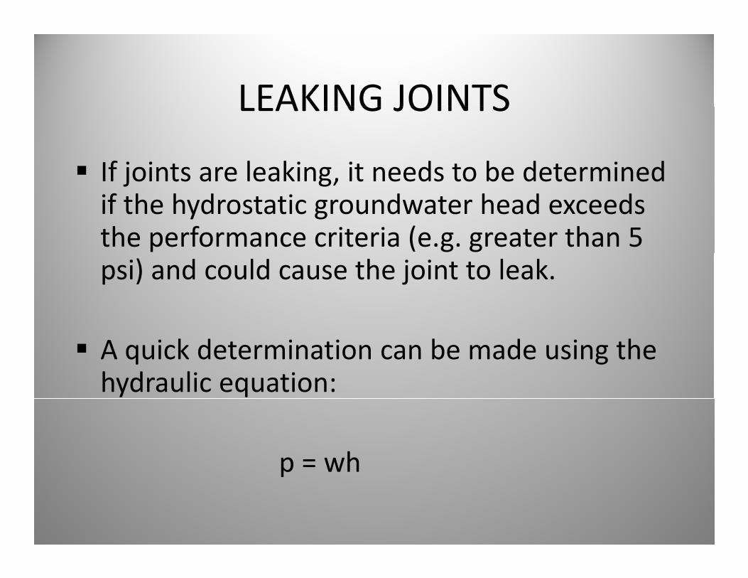
If joints are leaking, it needs to be determinedIf joints are leaking, it needs to be determined if the hydrostatic groundwater head exceeds the performance criteria (e.g. greater than 5 psi) and could cause the joint to leak.
A quick determination can be made using the hydraulic equation:
p = whp wh
LEAKING JOINTSLEAKING JOINTS
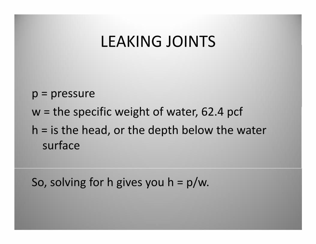
p = pressure
w = the specific weight of water, 62.4 pcf
h = is the head, or the depth below the water surface
So, solving for h gives you h = p/w.
LEAKING JOINTSLEAKING JOINTS
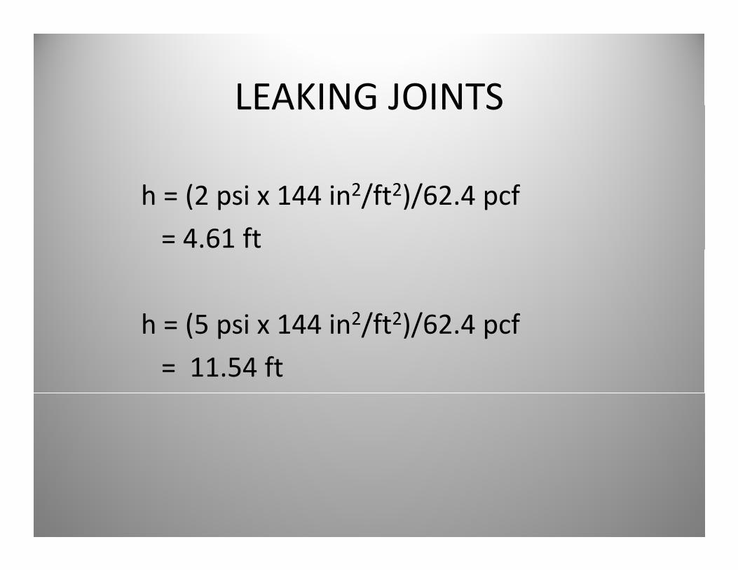
h = (2 psi x 144 in2/ft2)/62.4 pcf
= 4.61 ft
h (5 psi x 144 in2/ft2)/62 4 pcfh = (5 psi x 144 in2/ft2)/62.4 pcf
= 11.54 ft
LEAKING JOINTSLEAKING JOINTS
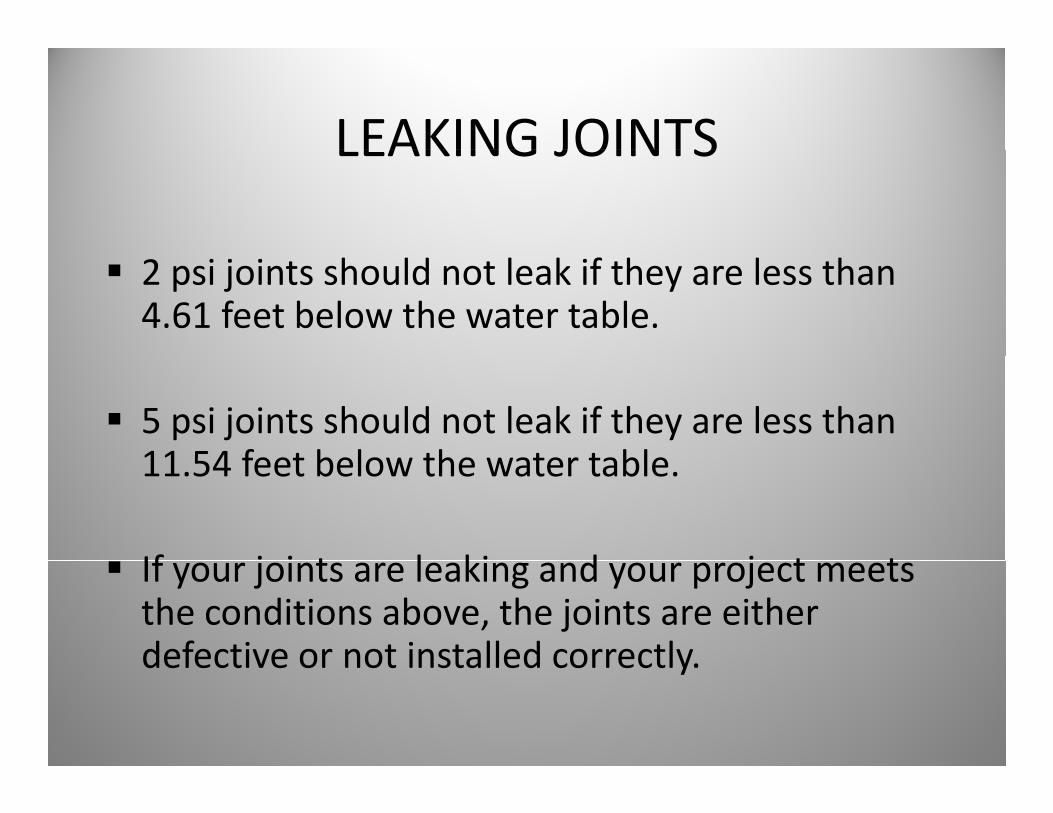
2 psi joints should not leak if they are less than 4.61 feet below the water table.
5 psi joints should not leak if they are less than 11 54 feet below the water table11.54 feet below the water table.
If j i t l ki d j t tIf your joints are leaking and your project meets the conditions above, the joints are either defective or not installed correctlydefective or not installed correctly.
LEAKING JOINTSLEAKING JOINTSSo, if your joints are leaking what do you do:
The contractor submits proposed repairs to the Engineer for review. The Engineer will determine which method of repair to use that is acceptablewhich method of repair to use that is acceptable to the Department. The solutions can range from methods in the Repair Matrix to nothing depending on the Engineer’s judgment.
JOINT GAPSJOINT GAPS
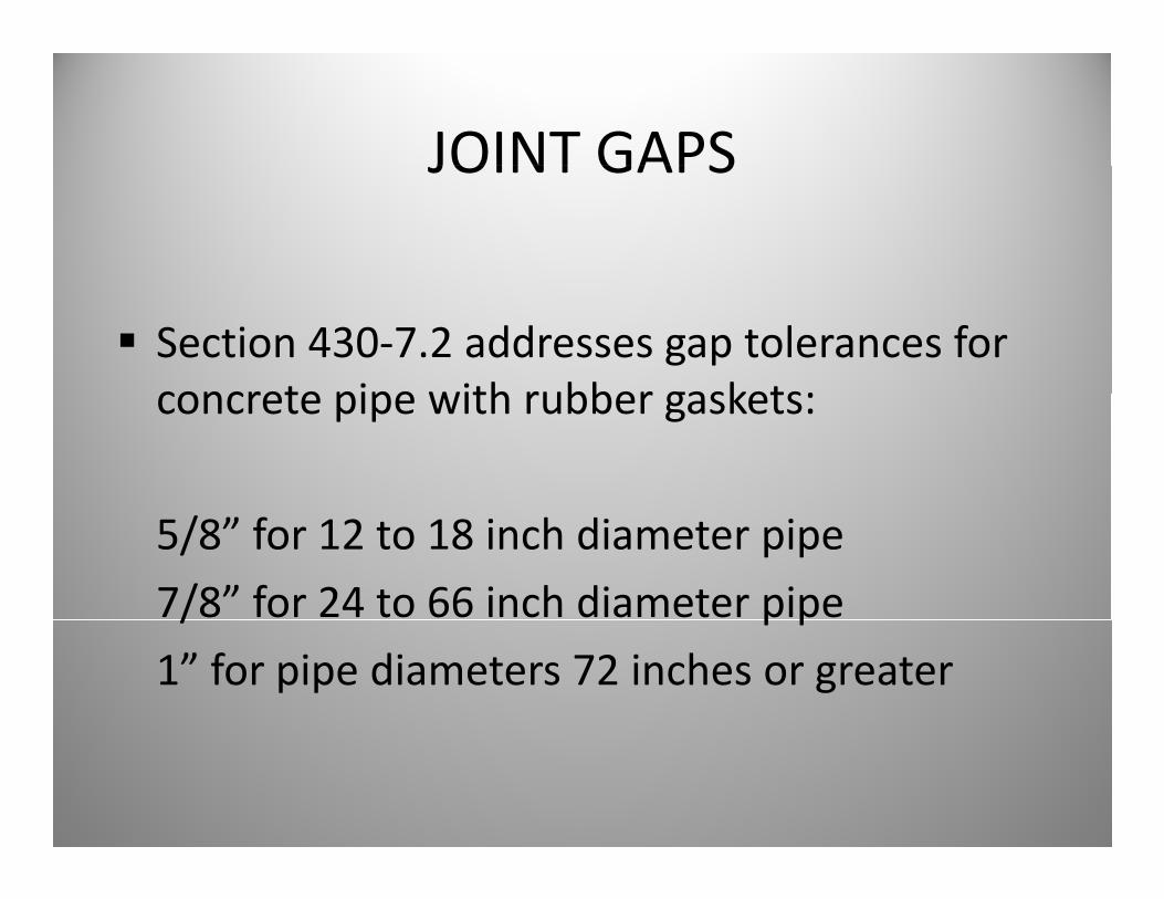
Section 430‐7.2 addresses gap tolerances for concrete pipe with rubber gaskets:concrete pipe with rubber gaskets:
5/8” for 12 to 18 inch diameter pipe
7/8” for 24 to 66 inch diameter pipe/ p p
1” for pipe diameters 72 inches or greater
JOINT GAPSJOINT GAPS
Where minor imperfections in the manufacture of the pipe create an apparentmanufacture of the pipe create an apparent gap in excess of the tabulated gap, the Engineer will accept the joint provided thatEngineer will accept the joint provided that the imperfection does not exceed 1/3 the circumference of the pipe and the rubbercircumference of the pipe, and the rubber gasket is 1/4 inch or more past the pipe joint entrance taperentrance taper.
JOINT GAPSJOINT GAPS
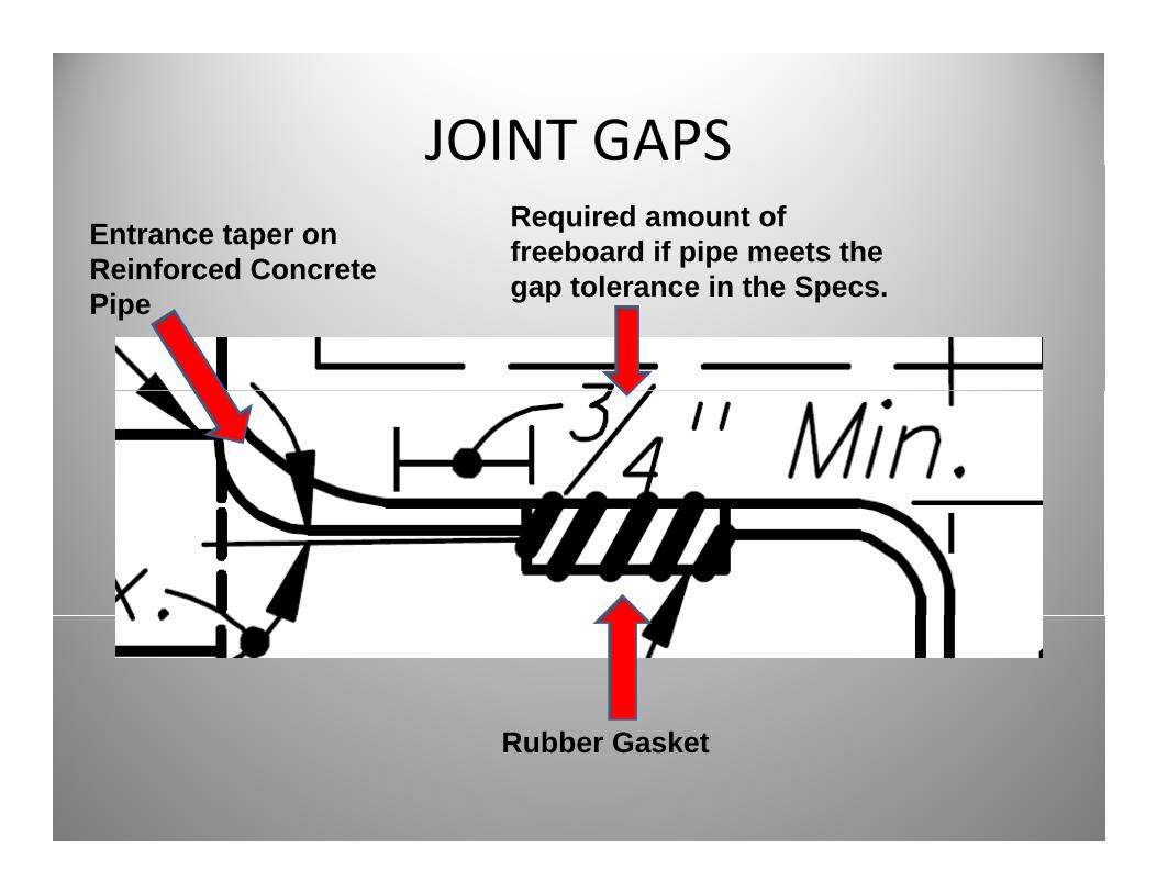
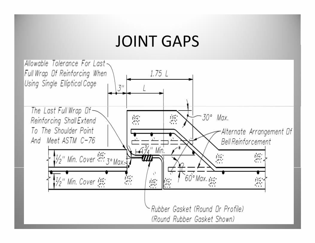
JOINT GAPSEntrance taper on Reinforced Concrete
Required amount of freeboard if pipe meets the
t l i th SReinforced Concrete Pipe gap tolerance in the Specs.
Rubber Gasket
JOINT GAPSJOINT GAPS
What happens if the joints that are installedWhat happens if the joints that are installed are outside of the tolerances?
Section 430‐7.2 states: “Where concrete pipes are outside of these tolerances, replace themare outside of these tolerances, replace them at no expense to the Department. Do not apply mortar, joint compound, or other filler to the gap which would restrict the flexibility of the joint.”
JOINT GAPSJOINT GAPS
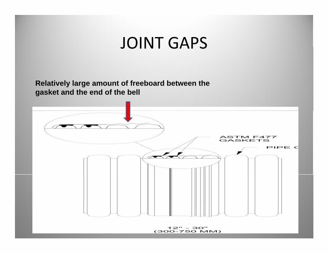
Relatively large amount of freeboard between the gasket and the end of the bell
JOINT GAPSJOINT GAPS
Thermoplastic pipes have a significant amount p p p gof freeboard in the bell design and are inherently less susceptible to leakage as a y p gresult of joint gaps.
NCHRP 15‐38 is currently reviewing design of culvert jointsculvert joints.
JOINT GAPSJOINT GAPS
So if you have joints gaps in your drainageSo, if you have joints gaps in your drainage system, what do you do:
The contractor submits proposed repairs to the Engineer for review The Engineer will determineEngineer for review. The Engineer will determine which method of repair to use that is acceptable to the Department. The repairs can range fromto the Department. The repairs can range from methods in the Repair Matrix to nothing depending on the Engineer’s judgment.
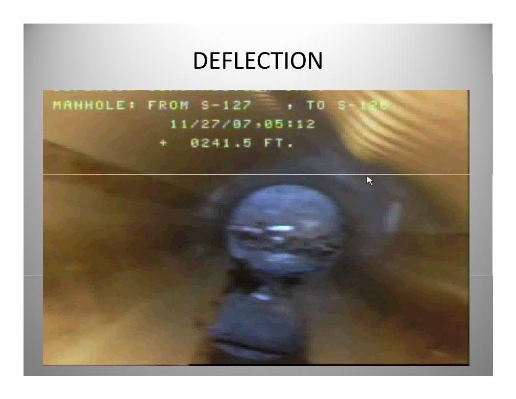
DEFLECTION
DEFLECTIONDEFLECTION
All flexible pipe types must meet theAll flexible pipe types must meet the Department’s deflection criteria in Section 430430.
Pi d fl d 5% f h ifi dPipe deflected 5% or more of the certified actual mean diameter of the pipe at final i i h ll b l d hinspection shall be replaced at no cost to the Department.
DEFLECTIONDEFLECTION
The Department is aware of the AASHTO standard for deflection and the critical limits of deflections for flexible pipe types.
However, the language in the current Specifications states that 5% deflection is theSpecifications states that 5% deflection is the cutoff for acceptance for flexible pipe types.
DEFLECTIONDEFLECTION
So if you have pipe runs with deflectionsSo, if you have pipe runs with deflections greater than 5% of the certified mean diameter you currently only have one option:diameter, you currently only have one option:
1 R d l th d fl t d ti1. Remove and replace those deflected sections at no cost to the Department.
CRACKINGCRACKING
CRACKINGCRACKING
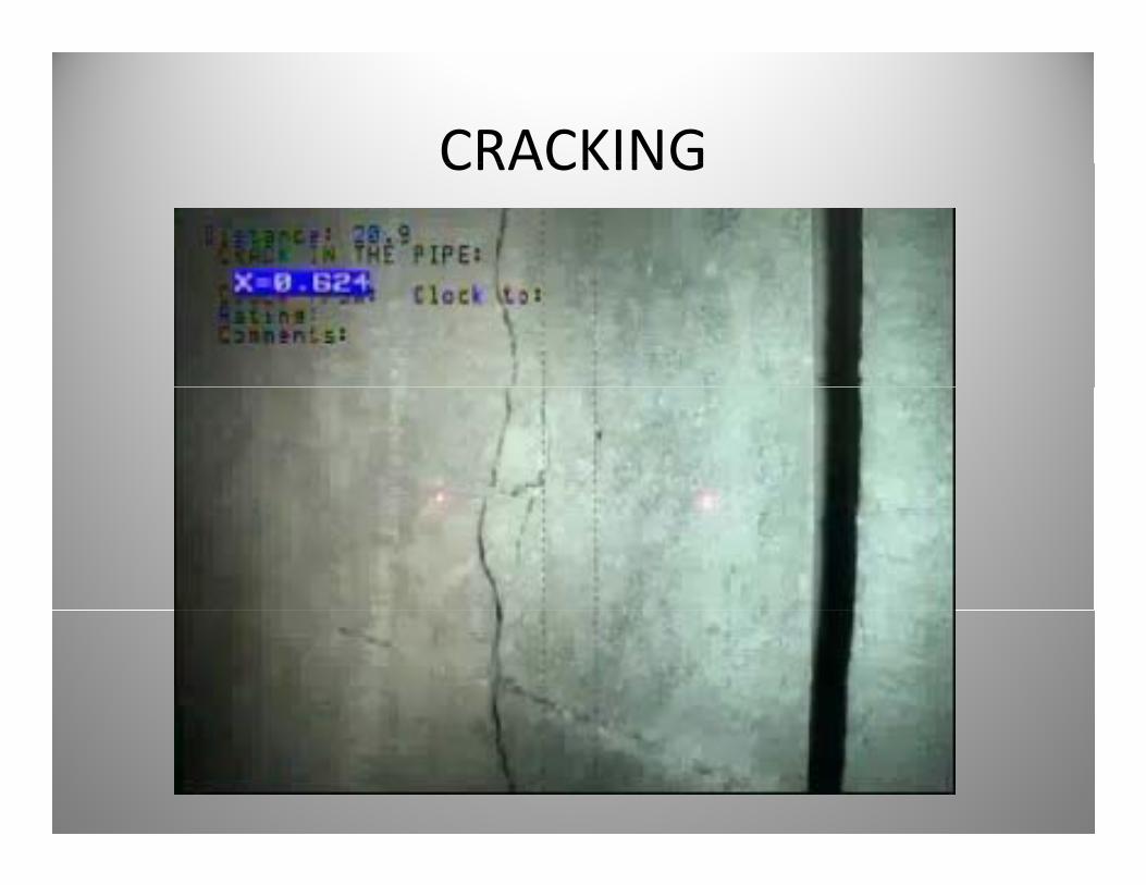
Cracking can occur in all pipe typesCracking can occur in all pipe types.
h i ill k h d i iThe Engineer will make the determination on the appropriate action.
If the pipe is cracked during installation, it is p p g ,usually due to the pipe being overloaded or not backfilled properly.p p y
CRACKINGCRACKING
Cracking can affect the structural integrity of the pipethe pipe.
The limits of cracking are defined in several documents by reference in the contract.
CRACKINGCRACKING
AASHTO S ti 27 6 4 t t th t “C k h iAASHTO Section 27.6.4 states that “Cracks having widths equal to or greater than 0.01 in and determined to be detrimental shall be sealed by adetermined to be detrimental shall be sealed by a method approved by the Engineer.”
“An evaluation shall be conducted by the Contractor and shall be submitted to the Engineer for review and approval considering the structural integrity, environmental conditions, and the design service life of the culvert ”and the design service life of the culvert.”
CRACKINGCRACKINGSo, if you have cracks in Reinforced Concrete Pipe that meet or exceed the 0 01 in crack criteria orthat meet or exceed the 0.01 in crack criteria or any cracks in a flexible pipe type, what do you do?
Submit an evaluation of the cracks considering the structural integrity environmental conditions and thestructural integrity, environmental conditions and the design service life of the pipe; and/or submit proposed repairs to the Engineer for review. The Engineer will determine which method of repair toEngineer will determine which method of repair to use that is acceptable to the Department. The repairs can range from methods in the Repair Matrix to nothing depending on the Engineer’s judgment.ot g depe d g o t e g ee s judg e t
So, how do we fix this stuff?So, how do we fix this stuff?
Currently, the Department relies on Section 431 –y, pPipe Liner to address pipe repair issues.
This specification is under review for updating to include the most current pipe repair materials and methods available to the contractor.and methods available to the contractor.
NCHRP 14‐19 – “Culvert Rehabilitation to Maximize Service Life While Minimizing Direct Costs and Traffic Disruption”
PIPE REPAIRPIPE REPAIRInformation on the NCHRP study can be found here:http://144.171.11.40/cmsfeed/TRBNetProjectDisplay.asp?ProjectID=1634
In lieu of the results of the NCHRP study, theIn lieu of the results of the NCHRP study, the Department has developed a Pipe Repair Matrix to assist the Engineer at the District level in making decisions.
This matrix is a GUIDELINE and does not replace proper pipe installation or sound engineering judgmentjudgment.
MATRIX BACKGROUNDMATRIX BACKGROUND
The Repair Matrix is a compilation of Department e epa at s a co p at o o epa t e tSpecifications, Design Standards and repair procedures submitted by members of FDOT’s
d ( ) d hPipe Advisory Group (PAG) and the Pipe Installation Task Group (PITG).
Both groups consist of members from the pipe manufacturing industry laser profiling andmanufacturing industry, laser profiling and inspections industry and technical experts in the field of drainage pipe.g p p
MATRIX BACKGROUNDMATRIX BACKGROUND
The Department asked its PITG members toThe Department asked its PITG members to submit repair methods for each of their particular pipe types and to provide any additional information that may be pertinent for repairs.
The PITG members responded with a variety of repairs they deemed suitable for their particular pipe types.
MATRIX BACKGROUNDMATRIX BACKGROUND
The Department compiled the informationThe Department compiled the information into an interactive spreadsheet for use by the Engineer when reviewing damaged pipe and possible repair methods.
The Matrix is a living document that will change as repair technology is updated and current methods are reviewed for their durability and performance.

SO, LETS ENTER…..,

PIPE REPAIR MATRIXPIPE REPAIR MATRIX
The Department encourages you to review theThe Department encourages you to review the Pipe Repair Matrix.
The Matrix can be found on the FDOT Construction Homepage under Contractor Issues.Construction Homepage under Contractor Issues.
Or it can be found here:Or, it can be found here:http://www.FDOT.state.fl.us/construction/ContractorIssues/PipeMatrix/MatrixMain.shtmctorIssues/PipeMatrix/MatrixMain.shtm
FINAL WORDS ON THE PIPE REPAIR MATRIX
Remember, the Matrix is a GUIDANCE document e e be , t e at s a GU C docu e tand does not replace the Specifications, proper installation or sound engineering judgment.
The Matrix is an evolving document that will continue to change with new advancements and additional research in pipe repair methods.
Ignoring the problem is not an option!

WHAT’S AHEAD FOR 2010WHAT S AHEAD FOR 2010
FDOT DIRECTION IN 2010FDOT DIRECTION IN 2010
Since last year the Construction Office has begunSince last year, the Construction Office has begun process reviews for drainage installation and spoken to both District Personnel and Contractors pregarding pipe inspection and repair.
Based on these reviews and interactions with CEIs and Contractors, the Department has notedand Contractors, the Department has noted opportunities for improvements in these Specifications.p
OPPORTUNITIES IN 2010OPPORTUNITIES IN 2010
S f h i i i l dSome of the opportunities include:
Standardizing Final Reports.
Review of variability among equipment manufacturers.
Increase training on interpretation of the Final Inspection ReportsInspection Reports.
GOALS FOR 2010GOALS FOR 2010
The Department is working on several updates toThe Department is working on several updates to Section 430, the laser profiling calibration criteria and Section 431 to address the some of the previous items.
This will be a partial update to the Specifications. We will have future updates addressing early pipeWe will have future updates addressing early pipe inspection and additional repair methods once those research projects are concluded.p j
UPDATES TO SECTION 430UPDATES TO SECTION 430
Section 430‐4.1 – General – Update thisSection 430 4.1 General Update this section of the Specification to require 5 psi as the minimum joint standard for all pipe applications. Higher pressure ratings may be required in the plans.
Completed January 2010
Section 430‐4.8 – Final Pipe Inspection –Require the removal of sediment or any other d b i i t i i ti Thi idebris prior to pipe inspection. This is incidental to the cost of the pipe installation.
UPDATES TO SECTION 430UPDATES TO SECTION 430
Final Pipe Inspection Reports – Re‐writing theFinal Pipe Inspection Reports Re writing the inspection requirements to focus on 3 core areas and eliminate some redundantareas and eliminate some redundant terminology. These areas include:
1. Joint Gap Report
2 Pipe Ovality Report2. Pipe Ovality Report
3. Pipe Defect Report
JOINT GAP REPORTJOINT GAP REPORT
A joint gap report would consist of a plan viewA joint gap report would consist of a plan view documenting all of the joints in a pipe run that do not meet the joint gap tolerances found indo not meet the joint gap tolerances found in Section 430‐7.2.
A photo of the joint and the actual ld b i l d d f hmeasurement would be included for each
location that is out of tolerance.
PIPE OVALITY REPORTPIPE OVALITY REPORT
The Pipe Ovality Report would include an initial measurement of the pipe diameter prior to profiling and contain a graph documenting the percentage of “Ovality” or deviation from thepercentage of “Ovality” or deviation from the original pipe diameter over the entire distance of a pipe run.a pipe run.
The 5% deflection limit would be highlighted andThe 5% deflection limit would be highlighted and any measurement over 5% would be displayed on the report in the location where it was noted.
PIPE DEFECT REPORTPIPE DEFECT REPORT
Similar to the Joint Gap Report, the Pipe Defect Report p p , p pwould consist of a plan view graphic documenting the location of all observed pipe defects in the pipe run.
Defects are considered as those items found during inspection that do not meet the Specifications.inspection that do not meet the Specifications.
At each location, the operator would note the defect pand provide a still image of the problem with the plan view.
INSPECTION REPORTSINSPECTION REPORTS
The Department will develop some sample reports for each of these areas and coordinate with the laser profiling and video inspection equipment manufacturers to provide a “standard” report that can be used by any system but present the information in a consistent format.
UPDATES TO SECTION 430UPDATES TO SECTION 430
Section 430‐4.8.1 – Video Report – The technical pportion of this section will be updated to the most current video format and may include new resolution requirements for video camerasresolution requirements for video cameras.
Clarify that the entire pipe is to be inspected, notClarify that the entire pipe is to be inspected, not just at the joints.
Require that the camera speed be included on the pipe video.
UPDATES TO SECTION 430UPDATES TO SECTION 430
Sections 430‐8 & 430‐9 – SpecificSections 430 8 & 430 9 Specific Requirements for Corrugated Metal, Corrugate Polyethylene and PolyvinylCorrugate Polyethylene, and Polyvinyl Chloride Pipe
FDOT is evaluating 100% compaction when backfilling all flexible pipe typesbackfilling all flexible pipe types.
UPDATES TO SECTION 431UPDATES TO SECTION 431
Section 431‐5 – Acceptance – “Inspect theSection 431 5 Acceptance Inspect the complete rehabilitation by means of closed circuit television Provide the Engineer withcircuit television… Provide the Engineer with videos of all preliminary and final inspections.”
Strengthen this language to make sure that video documentation of all repairs is provided to thedocumentation of all repairs is provided to the Engineer prior to final acceptance.

LASER PROFILINGLASER PROFILING
In an effort to improve the Specifications theIn an effort to improve the Specifications, the Department met with the manufacturers of all the Laser Profiling equipment presently used in g q p p ythe State of Florida on FDOT jobs.
On April 24, 2009, FDOT convened its first Laser Profiling Manufacturers Group to discuss reportProfiling Manufacturers Group to discuss report standardization, calibration criteria, equipment standards, and the Department’s needs., p
LASER PROFILINGLASER PROFILING
As a result of this meeting the Department isAs a result of this meeting, the Department is moving toward performance standards for laser profiling and video inspection equipment.p g p q p
FDOT will also require that any laser profilingFDOT will also require that any laser profiling equipment proposed be certified by an independent, accredited testing laboratory toindependent, accredited testing laboratory to meet the calibration criteria before it can be used on construction projects.p j
LASER PROFILINGLASER PROFILING
FDOT is also researching:
1. Requiring pipe inspection contractors to measure the di f h i h b i i f h i idiameter of the pipe at the beginning of the inspection.
2. Requiring video documentation of a field calibration of the laser profiling equipment using a known standard prior to inspection.
3. Requiring pipe inspection contractors to provide the camera speed on the video display.
4. Requiring training and certification for any person operating the video inspection and laser profiling equipment.q p
REPORT INTERPRETATION TRAININGREPORT INTERPRETATION TRAINING
The Construction Office intends to develop training on pipe report interpretation, compliancetraining on pipe report interpretation, compliance with the technical requirements of the Specifications and proper verification of the laser profiling calibration criteria.
AND FINALLYAND FINALLY,

QUALITY ASSURANCE REVIEWS!QUALITY ASSURANCE REVIEWS!
Currently, FDOT is in the process of purchasingCurrently, FDOT is in the process of purchasing its own laser profiling and video inspection equipment.
The Department will begin conducting QualityThe Department will begin conducting Quality Assurance Reviews (QARs) on randomly selected jobs in each of the Districts for the quality of the inspection reports submitted to FDOT.
QUESTIONS?????QUESTIONS?????