Embed Size (px)
Citation preview
José-Francisco Pérez-Calvo, Daniel Sutter, Matteo Gazzani, Marco Mazzotti Institute of Process Engineering, ETH Zurich
Distillation & Absorption 2018, September 16-19, 2018 Florence, Italy
Pilot Tests and Rate-Based Modelling of CO2 Capture in Cement Plants Using an Aqueous Ammonia Solution

| | Institute of Process Engineering 19-Sep-18 José-Francisco Pérez-Calvo, [email protected] 2
Talk outline
Introduction
Scope of the study
Pilot plant tests of the CO2 absorber
Rate-based model development
Rate-based model assessment using pilot plant test results
Conclusions
Pilot tests Introduction Scope Rate-based model Model assessment Conclusions

| | Institute of Process Engineering
Global cumulative CO2 emissions reductions 2020-2050
19-Sep-18 José-Francisco Pérez-Calvo, [email protected] 3
CO2 emissions from cement
Pilot tests Introduction Scope Rate-based model Model assessment Conclusions
2.2 Gt CO2 <> 7% global CO2 emissions
Source: International Energy Agency and Cement Sustainability Initiative (2018) Technology Roadmap – Low-Carbon Transition in the Cement Industry.
Fuel
Calcination
Electricity
CO2 emissions intrinsic to the
cement manufacturing process
Higher CO2 concentration in the
flue gas with respect to only
combustion

| | Institute of Process Engineering 19-Sep-18 José-Francisco Pérez-Calvo, [email protected] 4
The Chilled Ammonia Process
Pilot tests Introduction Scope Rate-based model Model assessment Conclusions
Similar process
complexity
Stable in the presence of
impurities
Global availability
Low environmental
footprint and cost
Competitive thermal
energy for regeneration

| | Institute of Process Engineering 19-Sep-18 José-Francisco Pérez-Calvo, [email protected] 5
The CO2-NH3-H2O system
Vapor
Liquid
Solid
H2O ↔ OH- + H+ NH3 + H+ ↔ NH4
+
HCO3- ↔ CO3
2- + H+ CO2 + OH- ↔ HCO3
-
CO2 + 2NH3 ↔ NH2COO- + NH4+
CO2 H2O NH3
CO2 H2O NH3
(NH4)HCO3 (NH4)2CO3·2NH4HCO3
(NH4)2CO3·H2O NH2COONH4 Ice
[1] Darde et al. Ind Eng Chem Res 49 (2010) 12663-74 [2] Jänecke Z Elektrochem 35 (1929) 9:716-28
SRK for gas fugacities
Extended UNIQUAC (Thomsen-Darde[1])
Solubility data for solids fitted on Jänecke[2]
Pure solids, activity = 1
VLE
SLE
Thomsen model to predict the system thermodynamics
Pilot tests Introduction Scope Rate-based model Model assessment Conclusions
| | Institute of Process Engineering 19-Sep-18 José-Francisco Pérez-Calvo, [email protected] 6
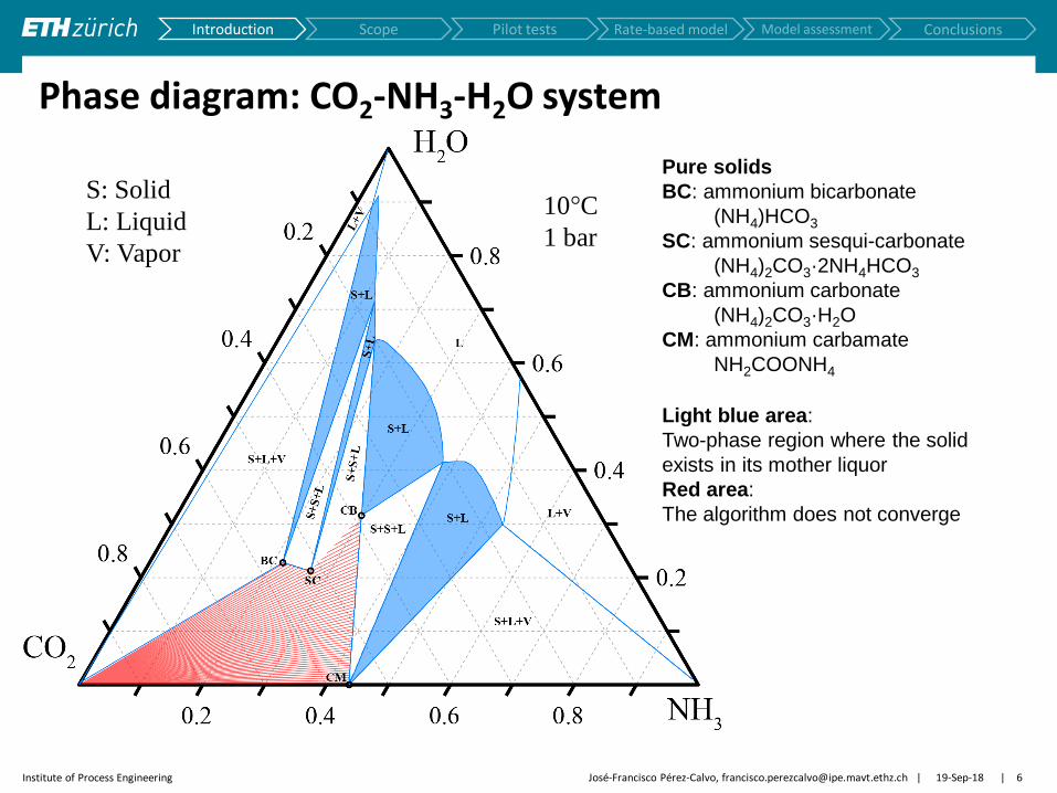
Phase diagram: CO2-NH3-H2O system
Pure solids
BC: ammonium bicarbonate
(NH4)HCO3
SC: ammonium sesqui-carbonate
(NH4)2CO3·2NH4HCO3
CB: ammonium carbonate
(NH4)2CO3·H2O
CM: ammonium carbamate
NH2COONH4
Light blue area:
Two-phase region where the solid
exists in its mother liquor
Red area:
The algorithm does not converge
10°C
1 bar
S: Solid
L: Liquid
V: Vapor
Pilot tests Introduction Scope Rate-based model Model assessment Conclusions

| | Institute of Process Engineering 19-Sep-18 José-Francisco Pérez-Calvo, [email protected] 7
Phase diagram: CO2-NH3-H2O system
[1] Jänecke Z Elektrochem 35 (1929) 9:716-728 [2] Sutter et al. Chem Eng Sci 133 (2015) 170-180
[1]
[2]
Pilot tests Introduction Scope Rate-based model Model assessment Conclusions

| | Institute of Process Engineering 19-Sep-18 José-Francisco Pérez-Calvo, [email protected] 8
From power plants to cement plants
NG power plants
~ 4 %vol. CO2
Coal-fired power plants
~ 14 %vol. CO2
Change of operating
conditions in the
CO2 absorber Cement plants
15 – 35%vol. CO2
Pilot plant CO2 absorption tests
1
Validation of rate-based models from literature
2
Development of new rate-based model
3
Assessment of new rate-based model performance
4
Research question:
Are the available rate-based models
valid or do they require adaptations?
Pilot tests Introduction Scope Rate-based model Model assessment Conclusions

| | Institute of Process Engineering 19-Sep-18 José-Francisco Pérez-Calvo, [email protected] 9
Test matrix definition
[1] Yu et al. Chem Eng Res Des 89 (2011) 1204-1215
Pilot tests Introduction Scope Rate-based model Model assessment Conclusions
CO2 content in
flue gas (%vol)
CSIRO[1]
This work
8.5 – 12
Up to 35
Packing type
Random 25 mm Pall ring
Structured Flexipac M 350X
Liquid properties

| | Institute of Process Engineering 19-Sep-18 José-Francisco Pérez-Calvo, [email protected] 10
Test matrix definition: Preliminary process optimization
Cement Plant
Power Plant
22%
18%
14% vol. CO2
Pilot tests Introduction Scope Rate-based model Model assessment Conclusions
Pérez-Calvo et al. Energy Procedia 114 (2017) 6197-6205

| | Institute of Process Engineering 19-Sep-18 José-Francisco Pérez-Calvo, [email protected] 11
Test matrix definition: Preliminary process optimization
Pilot tests Introduction Scope Rate-based model Model assessment Conclusions
[1] Yu et al. Chem Eng Res Des 89 (2011) 1204-1215
CO2 content in
flue gas (%vol)
CSIRO[1]
This work
8.5 – 12
Up to 35
Packing type
Random 25 mm Pall ring
Structured Flexipac M 350X
CSIRO pilot
tests[1]
Pilot tests – This work
Liquid properties

| | Institute of Process Engineering 19-Sep-18 José-Francisco Pérez-Calvo, [email protected] 12
Test rig
Pilot tests Introduction Scope Rate-based model Model assessment Conclusions
Controlled and
measured variables
Flowrate Temperature Pressure CO2 concentration NH3 concentration
CO2-lean solution Controlled and
measured variables
Flowrate Temperature CO2 concentration NH3 concentration
Measured variables
Flowrate Temperature Pressure CO2 concentration NH3 concentration
Measured variables
Flowrate Temperature CO2 concentration NH3 concentration

| | Institute of Process Engineering 19-Sep-18 José-Francisco Pérez-Calvo, [email protected] 13
Pilot test results
Raw data Steady-state
detection
𝑄Lin
,L/h
𝑄
Gou
t,A
m3
/h
𝑇,°
C
𝑃 Go
ut,k
Pa
𝑦,v
ol%
𝐶
CO
2,m
ol/
L
𝐶N
H3
,mo
l/L
𝑡, min
𝑇Lout
𝑇Gout
𝑇Lin
𝑦CO2
in
𝑦CO2
out
𝑦NH3
out
𝑀CO2
out
𝑀CO2
in
𝑀NH3
out
𝑀NH3
in
SS detected
No SS
Pilot tests Introduction Scope Rate-based model Model assessment Conclusions
Data Reconciliation
and
Gross Error Detection 𝒖, 𝝈 𝒖, 𝝈
82 experimental points

| | Institute of Process Engineering 19-Sep-18 José-Francisco Pérez-Calvo, [email protected] 14
Rate-based model
Pilot tests Introduction Scope Rate-based model Model assessment Conclusions
𝑁CO2= 𝐴eff𝐾G,CO2
(𝑝CO2,G − 𝑝CO2,L∗ )
Experimental value or
computed by the model
E = 𝑓(L-phase reactions)
𝐴eff = 𝑓hydrodynamics
transport properties
Rochelle model[1] to compute the effective G-L interfacial area
(𝑝CO2,G − 𝑝CO2 ,L∗ ) = 𝑓 thermodynamics
Thomsen thermodynamic model to compute the driving force
1
𝐾G,CO2
=𝑅𝑇
𝑘𝑔,CO2
+𝐻CO2
E𝑘𝑙,CO20
𝑘𝑔,CO2
𝑘𝑙,CO2
0 = 𝑓hydrodynamics
transport properties
Rochelle model[1] to compute the G-film and L-film mass-transfer coefficients
𝐻CO2= 𝑓 thermodynamics
Partition coefficient computed by Thomsen model
[1] Wang et al. Ind Eng Chem Res 55 (2016) 5357-5384
Range of structured packings
X, Y, Z, 150-350
Aqueous solutions for CO2
capture
Predicts SLE in addition to VLE
| | Institute of Process Engineering 19-Sep-18 José-Francisco Pérez-Calvo, [email protected] 15
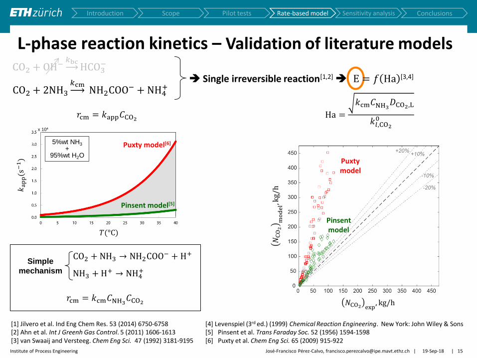
L-phase reaction kinetics – Validation of literature models
Pilot tests Introduction Scope Rate-based model Sensitivity analysis Conclusions
CO2 + 2NH3
𝑘cm NH2COO− + NH4
+
CO2 + OH−𝑘bc
HCO3−
Single irreversible reaction[1,2] E = 𝑓 Ha [3,4]
[1] Jilvero et al. Ind Eng Chem Res. 53 (2014) 6750-6758 [2] Ahn et al. Int J Greenh Gas Control. 5 (2011) 1606-1613 [3] van Swaaij and Versteeg. Chem Eng Sci. 47 (1992) 3181-9195
[4] Levenspiel (3rd ed.) (1999) Chemical Reaction Engineering. New York: John Wiley & Sons [5] Pinsent et al. Trans Faraday Soc. 52 (1956) 1594-1598 [6] Puxty et al. Chem Eng Sci. 65 (2009) 915-922
𝑇(°C)
𝑘a
pp
(s−
1)
5%wt NH3
+ 95%wt H2O
x 104
Puxty model[6]
Pinsent model[5]
CO2 + NH3 → NH2COO− + H+
NH3 + H+ → NH4+
𝑟cm = 𝑘app𝐶CO2
𝑟cm = 𝑘cm𝐶NH3𝐶CO2
Simple
mechanism
Ha =
𝑘cm𝐶NH3𝐷CO2,L
𝑘𝑙,CO2
0
Pinsent model
Puxty model
𝑁CO2 exp, kg/h
𝑁C
O2
mo
de
l,kg/
h

| | Institute of Process Engineering 19-Sep-18 José-Francisco Pérez-Calvo, [email protected] 16
L-phase reaction kinetics – Parameter estimation
Pilot tests Introduction Scope Rate-based model Sensitivity analysis Conclusions
CO2 + 2NH3
𝑘cm NH2COO− + NH4
+
CO2 + OH−𝑘bc
HCO3−
Single irreversible reaction[1,2] E = 𝑓 Ha [3,4]
CO2 + 2NH3 → NH2COO− + NH4+
Termolecular
mechanism
Ha =
𝑘cm𝐶NH3
𝑛 𝐷CO2,L
𝑘𝑙,CO2
0
CO2 + NH3 + H2O → NH2COO− + H3O+
CO2 + NH3 ↔ NH3+COO−
Zwitterion
mechanism NH3+COO− + NH3 → NH2COO− + NH4
+
𝑟cm = 𝑘cm𝐶NH3
𝑛 𝐶CO2
Empirical expression
1 ≤ 𝑛 ≤ 2
𝑘cm = 𝑘0cm,Trefexp −
𝐸a,cm
𝑅
1
𝑇−
1
𝑇ref
𝑘cm(𝑇 = 𝑇ref = 298 K) 𝐸a,cm 𝑛
m3
kmol s
kJ
kmol
−
This work 167 27,800 1.3
Pinsent 431 48,500 1
𝑁C
O2
mo
de
l,kg/
h
This work
Pinsent model
𝑁CO2 exp, kg/h
NH3+COO− + H2O → NH2COO− + H3O+

| | Institute of Process Engineering 19-Sep-18 José-Francisco Pérez-Calvo, [email protected] 17
Rate-based model performance assessment (1)
Pilot tests Introduction Scope Rate-based model Model assessment Conclusions
𝑙CO2, molCO2
/molNH3
𝑁C
O2,k
g/h
𝐶NH3= 5.5 − 5.8 m
𝑇L = 16 − 20°C 𝐿
𝐺= 8.5 − 8.8 kg/kg
𝑣𝑠,G = 0.9 − 1.0 m/s
𝒑𝐂𝐎𝟐,𝐆 = 𝟔 − 𝟕 𝐤𝐏𝐚
𝒑𝐂𝐎𝟐,𝐆 = 𝟏𝟐 − 𝟏𝟑 𝐤𝐏𝐚
𝒑𝐂𝐎𝟐,𝐆 = 𝟏𝟔 − 𝟏𝟖 𝐤𝐏𝐚
𝐶NH3= 5.8 − 6.1 m
𝑇L = 20 − 23°C 𝐿
𝐺= 10.7 − 11.5 kg/kg
𝑣𝑠,G = 0.7 m/s
𝑁C
O2,k
g/h
𝑙CO2
, molCO2/molNH3
𝒑𝐂𝐎𝟐,𝐆 = 𝟏𝟕 − 𝟏𝟗 𝐤𝐏𝐚
𝒑𝐂𝐎𝟐,𝐆 = 𝟑𝟎 − 𝟑𝟏 𝐤𝐏𝐚
Set A – low CO2 loading Set B – high CO2 loading

| | Institute of Process Engineering 19-Sep-18 José-Francisco Pérez-Calvo, [email protected] 18
Rate-based model performance assessment (2) 𝑁
CO
2,k
g/h
𝑁C
O2,k
g/h
𝑇L, °C 𝑇L, °C
𝑝CO2 ,G = 18 − 19 kPa
𝑙𝐶𝑂2= 0.47 − 0.54 molCO2
/molNH3
𝐿
𝐺= 7.6 − 8.8 kg/kg
𝑣𝑠,G = 0.9 − 1.1 m/s
𝑪𝐍𝐇𝟑= 𝟏𝟎 𝐦
𝑪𝐍𝐇𝟑= 𝟔 𝐦
𝑪𝐍𝐇𝟑= 𝟒 𝐦
𝑪𝐍𝐇𝟑= 𝟒 𝐦
𝑪𝐍𝐇𝟑= 𝟔 𝐦
𝑪𝐍𝐇𝟑= 𝟏𝟎 𝐦
𝑝CO2 ,G = 17 − 19 kPa
𝑙𝐶𝑂2= 0.52 − 0.54 molCO2
/molNH3
𝐿
𝐺= 10.7 − 11.4 kg/kg
𝑣𝑠,G = 0.7 m/s
Set C – low CO2 loading Set D – high CO2 loading
Pilot tests Introduction Scope Rate-based model Model assessment Conclusions

| | Institute of Process Engineering 19-Sep-18 José-Francisco Pérez-Calvo, [email protected] 19
Conclusions
The Chilled Ammonia Process is a very promising technology for CO2 capture from cement plants
It has been confirmed experimentally that the higher CO2 concentration in the flue gas enhances the absorption of CO2
CO2 capture efficiencies as high as 60% have been obtained in only 3 m high packing
The results of the CO2 absorption pilot plant tests have shown that the rate-based models available in the literature are outside their range of validity when used at the conditions of the CAP applied to cement plants
Therefore, a new rate-based model has been developed, that:
Is able to reproduce the trends of the CO2 absorption rate obtained experimentally
Can be used with engineering purposes for the simulation and optimization of the CAP applied to cement plants for CO2 capture
Pilot tests Introduction Scope Rate-based model Model assessment Conclusions

| | Institute of Process Engineering 19-Sep-18 José-Francisco Pérez-Calvo, [email protected] 20
Acknowledgements
This project has received funding from the European Union's Horizon 2020 research and innovation programme under grant agreement no 641185
This work was supported by the Swiss State Secretariat for Education, Research and Innovation (SERI) under contract number 15.0160

José-Francisco Pérez-Calvo, Daniel Sutter, Matteo Gazzani, Marco Mazzotti Institute of Process Engineering, ETH Zurich
Distillation & Absorption 2018, September 16-19, 2018 Florence, Italy
Pilot Tests and Rate-Based Modelling of CO2 Capture in Cement Plants Using an Aqueous Ammonia Solution