Embed Size (px)
Citation preview

Pilot Testing of a Membrane System for Post-Combustion CO2 Capture
DE-FE0005795
Karl Amo, Zhenjie He, Jurgen Kaschemekat, Tim Merkel, Saurabh Pande, Xiaotong Wei, Steve White (MTR)
Prasanna Seshadri and Hamid Farzan (B&W)
NETL CO2 Capture Technology Meeting Wednesday, July 10, 2013

Project Overview
2
Award name: Pilot testing of a membrane system for post-combustion CO2 capture Project period: 10/1/10 to 9/30/15 Funding: $15 million DOE; $3.75 million MTR DOE program manager: Jose Figueroa Participants: MTR, Babcock & Wilcox, SCS/NCCC, EPRI, Vectren
Project scope: Demonstrate a membrane process to capture 20 tons of CO2/day (TPD) from a flue gas slipstream of a coal-fired power plant.
Project plan: The key project work organized by budget period is as follows:
• BP1 – Membrane optimization though continued slipstream testing on the 1 TPD system and computational evaluation of sweep recycle with B&W
• BP2 – Design and construction of the 20 ton/day system, boiler testing at B&W with CO2-laden air; membrane/module optimization and durability testing through continued testing on 1 TPD system
• BP3 – 6-month pilot test of the 20 ton/day system; comparative economic analysis; industrial 1 TPD field test; Vectren case study at 20 MW-scale

3
Pros and Cons of a Membrane Post-Combustion Capture Process
Benefits:
• No hazardous chemical handling, emissions, or disposal issues
• Not affected by oxygen, SOx or NOx; co-capture possible
• Water use lower than other technologies (recovers H2O from flue gas)
• No steam use → no modifications to existing boiler/turbines
• Near instantaneous response; high turndown possible
• Very efficient at partial capture (~60%)
Challenges:
• How to generate a pressure driving force in an affordable manner?
• Very permeable/low cost membranes required
• Unknown impact of particulate matter on membrane-module lifetime
• Materials and performance challenges for rotating equipment used (blowers, compressors, vacuum pumps)
• Pressure drop and module flow distribution 3

MTR CO2 Capture Process
4 • Combustion air sweep provides driving force that lowers the capture energy • Pre-concentrated CO2 decreases membrane area and power required
18% O2, 8% CO2
20% CO2
CO2 depleted flue gas
U.S. Patents 7,964,020 and 8,025,715
(2) Impact of CO2 recycle
(1) Membrane and module performance
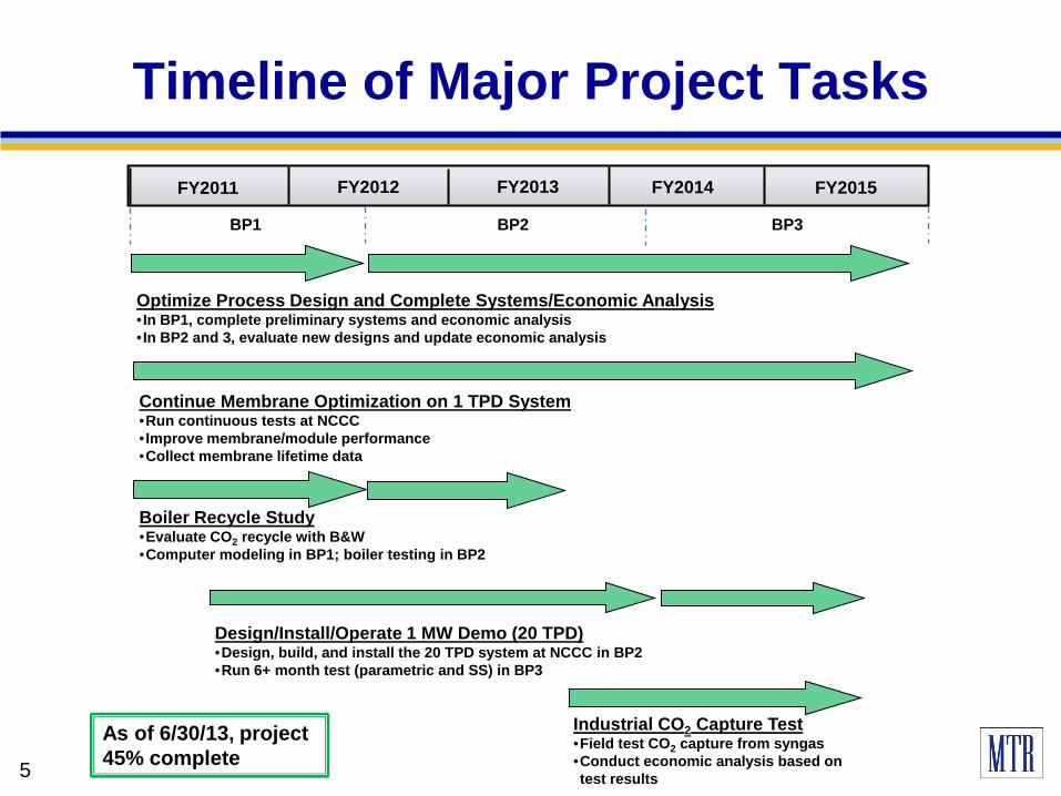
Timeline of Major Project Tasks
FY2011 FY2012 FY2013
Design/Install/Operate 1 MW Demo (20 TPD) •Design, build, and install the 20 TPD system at NCCC in BP2 •Run 6+ month test (parametric and SS) in BP3
Boiler Recycle Study •Evaluate CO2 recycle with B&W •Computer modeling in BP1; boiler testing in BP2
Continue Membrane Optimization on 1 TPD System •Run continuous tests at NCCC • Improve membrane/module performance •Collect membrane lifetime data
FY2014 FY2015
Optimize Process Design and Complete Systems/Economic Analysis • In BP1, complete preliminary systems and economic analysis • In BP2 and 3, evaluate new designs and update economic analysis
BP1 BP2 BP3
Industrial CO2 Capture Test •Field test CO2 capture from syngas •Conduct economic analysis based on test results 5 5
As of 6/30/13, project 45% complete

Systems Analysis: Importance of Membrane Improvements
30
40
50
60
70
80
90
100
100 1,000 10,000
Changein COE
(%)
Membrane CO2 permeance (gpu)
1st Generation Polaris
2nd Generation Polaris
MEA (DOE Case 10)
DOE Target
AdvancedPolaris
MTR membrane process assuming $50/m2
• Study completed in BP1 to meet a project milestone
• All calculations for 90% CO2 capture use Bituminous Baseline report methodology
• Higher permeance (lower cost) membranes are key to approaching DOE goals
• Results are generally consistent with independent findings reported in DOE report “Current and Future Technologies for Power Generation with Post-Combustion Carbon Capture” (DOE/NETL-2012/1557)
6 6

0
10
20
30
40
50
60
70
0 1,000 2,000 3,000
CO2/N2
selectivity
CO2 permeance (gpu)
PolarisTM
base caseProject target
area
Commercial CO2 membranes
BP1 lab membranes
BP2 production membranes
BP2 labmembranes
Membrane Performance Improvements
7 Pure-gas data at 25°C and 50 psig feed pressure; 1 gpu = 10-6 cm3(STP)/(cm2 s cmHg) 7
• Membranes continue to improve
• In addition to lower cost, these improvements are important to shrink the size of the capture system
7

1 TPD System at NCCC
8
Membrane vessels
• System is testing vacuum and air sweep membrane steps • Sized to capture 1 ton CO2/day using commercial 40-inch-long modules • System installed Nov 2011; operation started Spring 2012 8

Sample Results at NCCC
9 9
CO2 Concentration Capture Rate
Most concentration fluctuations due to changes in feed gas temperature
0
10
20
30
40
50
60
70
80
0 100 200 300 400 500 600
CO
2 c
onte
nt (%
)
Cumulative run time (h)
CO2-enriched permeate
Flue gas feed
CO2-depleted residue
0
20
40
60
80
100
0 100 200 300 400 500 600
Cap
ture
rate
(%)
Cumulative run time (h)
9

Correlation of CO2 Purity and Capture Rate With Temperature
10
0
20
40
60
80
100
30 40 50 60 70 80
CO
2 per
mea
te c
once
ntra
tion
(%)
Operating temperature (oF)
• Higher temperatures yield higher gas permeances, leading to greater CO2 capture, but at lower purity; could be controlled by switching modules on and offline depending on temperature.
0
20
40
60
80
100
30 40 50 60 70 80
CO
2 cap
ture
rate
(%)
Operating temperature (oF)
CO2 Concentration Capture Rate

1 TPD System: Lessons Learned
11
• In July 2012, compressor failed due to extensive deposition of unknown material • NCCC and MTR analyses indicate presence of water soluble sulfur salts
(ammonium sulfate/bisulfate, iron sulfate) • It is believed these salts were created in SCR/FGD operation upstream of the
membrane, and were present as aerosols in the flue gas fed to the system • A more solids-tolerant liquid ring compressor was installed; appears to effectively
remove acidic aerosol in sealing water
Material dissolved in water 11 Motor element showing deposition

1 TPD System: Lessons Learned
12 12
• After compressor failure, system continued operating with vacuum only until Sept 2012
• Membranes showed stable performance during this time
• After shutdown at end of Sept, it was found that condensed water with dissolved sulfate salts collect on surface of membrane, and resulted in low CO2 flux
• To prevent future occurrence, system shutdown procedure changes, and module material solutions developed
• Several startup/shutdown cycles since these changes show stable membrane performance
Membrane
Feed spacer
Flue gas flow direction

20 TPD System Status
• 20 TPD skid (1 MWe) design is complete; now under construction
• Fabrication and site preparation on schedule
• Planned installation at NCCC in 1Q2014, followed by 6 month demonstration
• Will test 2nd generation modules designed for low pressure drop while minimizing footprint (cost)
13

20 TPD System Location at NCCC/PC4
Flue Gas In Flue Gas
Return
0.5 MWe pilot solvent
test unit
Picture courtesy of Mr. Tony Wu, Southern Company
14

Impact of CO2 Recycle on Boiler Performance
Phase I (BP1) – CFD modeling • B&W modeled 2 boiler configurations (radiant boiler firing bituminous coal
and SWUP firing PRB coal) and 2 sweep recycle cases (constant secondary air flow and constant stoichiometry)
• Main conclusion of modeling study: secondary air laden with CO2 appears feasible as a retrofit in either of the boiler configurations examined if oxygen mass flow to boiler is fixed
Phase II (BP2) – Pilot testing • B&W’s SBS-II 1.8 MWth pilot boiler operated with CO2-laden combustion air
• Two coals evaluated: a western sub-bituminous coal and a highly volatile bituminous coal
• O2 content of windbox air varied from 21% to 16% through CO2 dilution
• Monitored flame stability, length, and shape; unburned combustibles in fly ash, and furnace exit gas temperature
• Radiant furnace and convective pass heat absorptions were measured
• Boiler efficiencies for air and sweep firing being determined 15 15

Air-Firing Sweep Air-Firing
Conditions: 5 MMBtu/h with sub-bituminous coal; deep staged flame, stoichiometry 0.8; sweep air is 18% O2
Viewpoint is from top of boiler looking down at flame
Baseline and Sweep Air Flames with a Western Sub-Bituminous Coal
16

Boiler Study Preliminary Findings
17
• Pilot-scale evaluation shows that stable flames can be obtained with sweep air (in fact B&W analysis indicates sweep flame is more stable due to additional combustion air swirl)
• Although flame is stable down to 16% O2, for existing boilers, 18% is preferred to minimize increased mass through boiler
• Data analysis to determine the effect of sweep air on boiler efficiency and the potential need for additional heat transfer surface area is ongoing
• Findings will be used to update BP1 techno-economic analysis
18
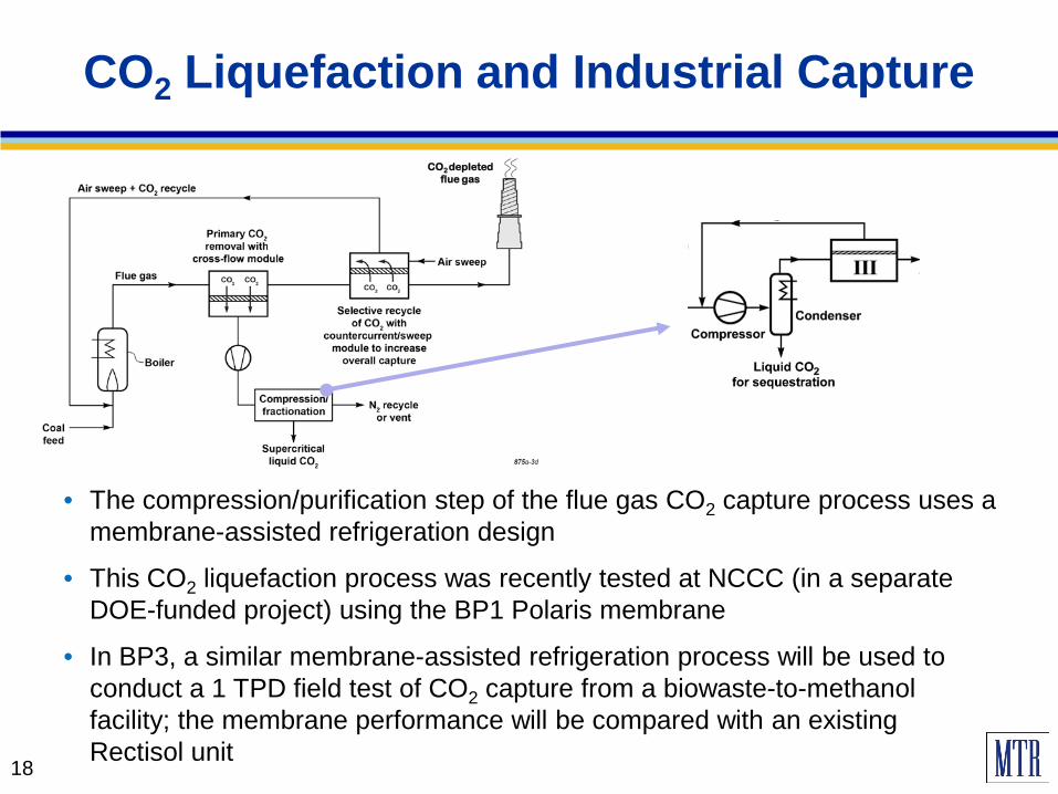
CO2 Liquefaction and Industrial Capture
• The compression/purification step of the flue gas CO2 capture process uses a membrane-assisted refrigeration design
• This CO2 liquefaction process was recently tested at NCCC (in a separate DOE-funded project) using the BP1 Polaris membrane
• In BP3, a similar membrane-assisted refrigeration process will be used to conduct a 1 TPD field test of CO2 capture from a biowaste-to-methanol facility; the membrane performance will be compared with an existing Rectisol unit
CO2 depleted flue gas

Summary
• Post-combustion capture membrane performance continues to improve
• Bench-scale slipstream tests at NCCC show membrane modules capable of generally stable 90% capture
• Many useful lessons learned from operating with real flue gas; NCCC assistance has been invaluable
• B&W CFD analysis and flame stability tests suggest CO2 recycle with sweep membrane is feasible; detailed analysis ongoing
• Industrial CO2 capture membranes have demonstrated liquid CO2 production; industrial field tests planned
• Key objective of next 12 months is fabrication, installation, and operation of the 20 TPD demonstration unit
19
U.S. Department of Energy, National Energy Technology Laboratory
– Jose Figueroa
Southern Company Services (NCCC)
Acknowledgements
20 20


![Post-combustion CO capture with a commercial activated ...digital.csic.es/bitstream/10261/102946/1/Post-combustion...post-combustion capture compared to amine scrubbing [3-5]. Two](https://img.pdfslide.us/doc/110x75/60d72e456c93bf1aee2edae5/post-combustion-co-capture-with-a-commercial-activated-post-combustion-capture.jpg)