Embed Size (px)
Citation preview

EATON SystemStak™ Valves Size 08 E-VLVI-SS001-E1 October 2015P-2
P
SystemStak™ Pilot Operated Check ValveSeries DGMPC-H8
General Description
Features:
• Industry Standard Mounting, ISO 4001-8, NFPA T 3.51 M R1 and ANSI B 93.7 D08
• For use in vertical stacking assemblies
• For the leak free closure of one or both service ports
General
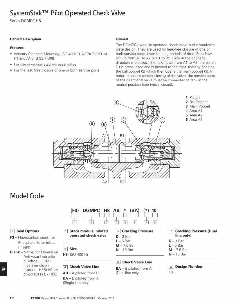
The DGMPC hydraulic operated check valve is of a sandwich plate design. They are used for leak-free closure of one or both service ports, even for long periods of time. Free flow occurs from A1 to A2 or B1 to B2. Flow in the opposite direction is blocked. The fluid flows from A1 to A2, the piston (1) is pressurized and is pushed to the right, thereby opening the ball poppet (2) which then opens the main poppet (3). In order to ensure correct closing of the valve, the service ports of the directional valve must be connected to tank in the neutral position (see typical circuit).
A
A1
B
B1
A2 B2
P T
A2 B2
A1 B1
A2 B2
A1 B1
A2 B2
A1
AB*- BA* AB* BA*
B1
26 5
1
A1 B1
A2 B2
3
4
Symbols
1 Piston2 Ball Poppet3 Main Poppet4 Area A15 Area A26 Area A3
Typical Circuit
(F3) DGMPC H8 AB * (BA) (*) 10
1 2 3 84 65 7
Seal Options
F3 – Fluorocarbon seals, for Phosphate Ester (class L - HFD)
Blank – Nitrile, for Mineral oil Anti-wear hydraulic oil (class L - HM), Invert emulsion (class L - HFB) Water glycol (class L - HFC)
Stack module, piloted operated check valve
Size
H8- ISO 4001-8
Check Valve Line
AB – A piloted from BBA – B piloted from A(Single line only)
Cracking Pressure
K – 3 BarL – 5 BarM – 7.5 BarN – 10 Bar
Check Valve Line
BA – B piloted from A(Dual line only)
Cracking Pressure (Dual line only)
K – 3 BarL – 5 BarM – 7.5 BarN – 10 Bar
Design Number
10
1
4
5
6
7
8
2
3
Model Code

EATON SystemStak™ Valves Size 08 E-VLVI-SS001-E1 October 2015 P-3
P
A
A1
B
B1
A2 B2
P T
A2 B2
A1 B1
A2 B2
A1 B1
A2 B2
A1
AB*- BA* AB* BA*
B1
26 5
1
A1 B1
A2 B2
3
4
Symbols
1 Piston2 Ball Poppet3 Main Poppet4 Area A15 Area A26 Area A3
Typical Circuit
Operating Data
Functional Symbols
Technical Data
Maximum Flow (L/min) 450Maximum Operating Pressure (bar) 315Cracking Pressure See “Characteristic Curves” graph page 3Area Ratio A1/A2 = 1/13.6;A3/A2 = 1/2.8Fluid Mineral oils or phosphate esterFluid Temperature Range (0C) -20 to 80Fluid Viscosity Range (mm2/S) 2.8 to 500Fluid Cleanliness Level (ISO) 19/17/14Weight (Kg) 12
Performance Data
Characteristic Curves (measured at v = 41mm2/s
and t = 50 ºC)
Solid LineA1 - A2; B1 - B2
Dotted LineA2 - A1; B2 - B1
Flow in L/min
Pre
ssu
re D
rop
(b
ar)
0
5
10
15
20
25
30
100 15050 200 250 300 350 400 450
N
ML
K
Cracking Pressure:
K – 3 bar L – 5 bar M – 7.5 bar N – 10 bar

EATON SystemStak™ Valves Size 08 E-VLVI-SS001-E1 October 2015P-4
P
Installation Dimensions(Dimensions in mm)
Required surface finish of mating face
0.8
0.01/100mm
100
300
94.3
T
L
X
29.2
5377
13071.4
41.4
46
117
92 96.8
A B
YP
4
270
2.22.1
6
1
2
3
5
270
240
59
4
2 x φ 6.5/deep 8
1 Cracking pressure 3 bar or 5 bar, check valve on both ports A and B 2 Cracking pressure 7.5 bar or 10 bar, check valve on both ports A and B 2.1 Cracking pressure 7.5 bar or 10 bar, check valve on port A 2.2 Cracking pressure 7.5 bar or 10 bar, check valve on port B 3 Name plate 4 Valve mounting holes, 6 x 15mm 5 Locating pins 6 Locating pin hole
Mounting bolts: 1/2 -UNC, SAE, Grade 8; M14, DIN912-10.9; ISO 898, Class 12.9 Torque 150 lb-ft (250 Nm) O-rings: 27mm x 3mm for ports A,B,P and T. O-rings: 19mm x 3mm for ports X,Y, and L.
EATON SystemStak™ Valves Size 08 E-VLVI-SS001-E1 October 2015 P-5
P
SystemStak™ Throttle Valve with CheckSeries DGMFN-H8
General Description
Features:
• Industry standard mounting, ISO 4401-8, NFPNA-T-3 .5.1-M-R-I, ANSI B 93.7 D08
• Sandwich plate design
• Limiting of main flow of two actuator ports
• Meter-in or meter-out control
General
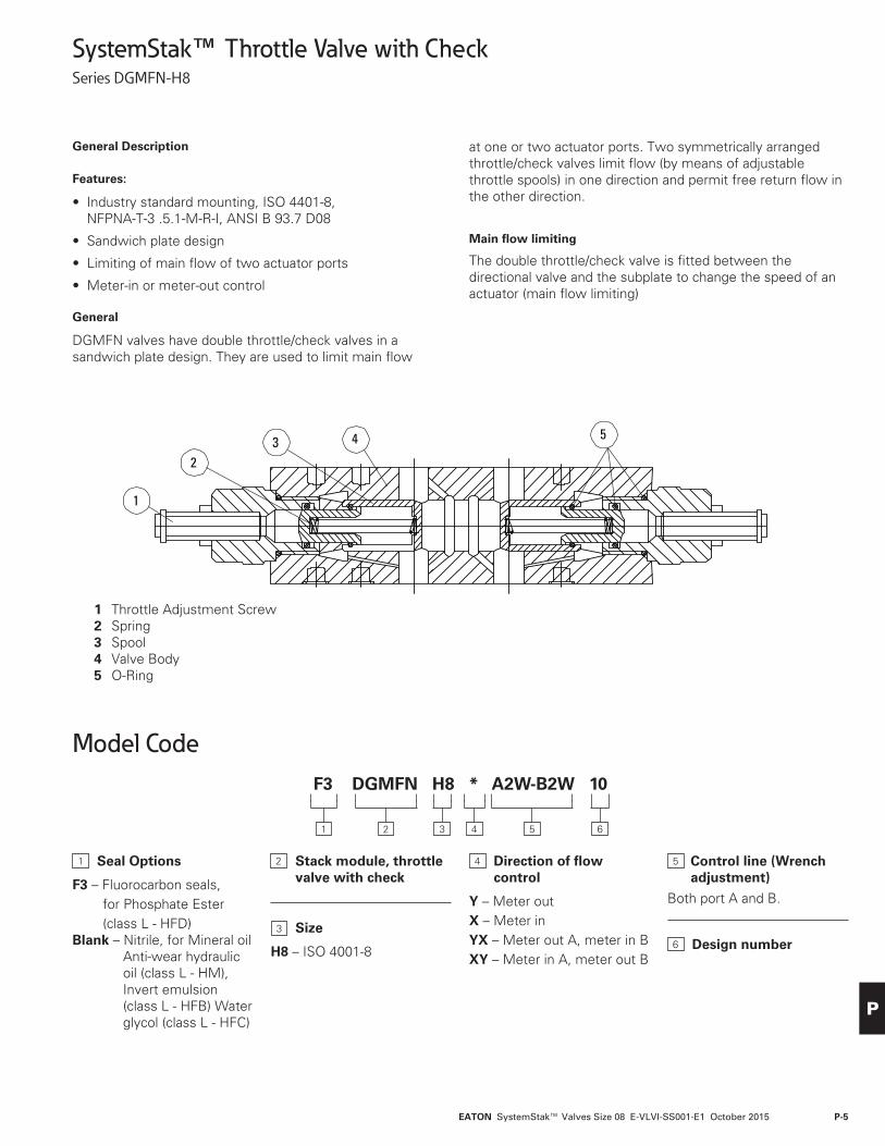
DGMFN valves have double throttle/check valves in a sandwich plate design. They are used to limit main flow
at one or two actuator ports. Two symmetrically arranged throttle/check valves limit flow (by means of adjustable throttle spools) in one direction and permit free return flow in the other direction.
Main flow limiting
The double throttle/check valve is fitted between the directional valve and the subplate to change the speed of an actuator (main flow limiting)
B Meter-out control: XYA Meter-in control
B Meter-in control: YXA Meter-out control
Meter-in control...X Meter-out control...Y
A B A B A B A B
1
23 4 5
1 Throttle Adjustment Screw 2 Spring 3 Spool 4 Valve Body 5 O-Ring
Model CodeF3 DGMFN H8 * A2W-B2W 10
1 2 3 64 5
Seal Options
F3 – Fluorocarbon seals, for Phosphate Ester (class L - HFD)
Blank – Nitrile, for Mineral oil Anti-wear hydraulic oil (class L - HM), Invert emulsion (class L - HFB) Water glycol (class L - HFC)
Stack module, throttle valve with check
Size
H8 – ISO 4001-8
Direction of flow control
Y – Meter outX – Meter inYX – Meter out A, meter in BXY – Meter in A, meter out B
Control line (Wrench adjustment)
Both port A and B.
Design number
1 4 5
6
2
3

EATON SystemStak™ Valves Size 08 E-VLVI-SS001-E1 October 2015P-6
P
Technical Data
Maximum Flow (L/min) 350Maximum Working Pressure (bar) 315Fluid Mineral oils or phosphate esterFluid Temperature Range (0 C) -20 to + 80Fluid Viscosity Range (mm2/S) 2.8 to 500Fluid Cleanliness Level (ISO) 19/17/14Weight (Kg) 8
Operating Data
Performance Data
Characteristic Curves(measured atv = 41 mm2⁄s andt = 50ºC)
Th
rott
le s
etti
ng
in t
urn
s
Pre
ssu
re D
rop
in b
ar
Throttle flow pressure drop
DGMFN-H8
0
1
510
20
40
60
80
100
150
200
2504 5 6 7 8
9
10
11
12131517
50 100 150 200 250 300 350
Pre
ssu
re D
rop
in b
arCheck free flow pressure drop
Flow in L/min
0
10
20
3040
60 12 0 1 80 240 30 0 360
DGMFN-H8
B Meter-out control: XYA Meter-in control
B Meter-in control: YXA Meter-out control
Meter-in control...X Meter-out control...Y
A B A B A B A B
1
23 4 5
Functional Symbols

EATON SystemStak™ Valves Size 08 E-VLVI-SS001-E1 October 2015 P-7
P
Installation Dimensions(Dimensions in mm)
Required surface finish of mating face
0.8
0.01/100mm
1
7
640.8130
100.6
77
17.317.2
L
X
T P
A B
Y
8
2 34
5
96.8
92
7346
1917.5
74.5
55
324.7 117
φ6
268188
112.5
4
76.853
29.25.6
2 x φ6.5/deep 8
6 x φ15
1 Name plate 2 Screw for flow adjustment 3 Turn anti-clockwise = increases flow, turn clockwise = decreases flow 4 Two locating pins 5 Two locating pin holes 6 Valve mounting holes 7 O-ring ports A,B,P,T 8 O-ring ports X,Y,L
Mounting bolts: ½-UNC, SAE, Grade 8; M14, DIN912-10.9; ISO 898, Class 12.9 Torque 150 lb-ft (250 Nm) O-Ring: 27mm x 3mm for port A,B,P and T O-Ring: 19mm x 3mm for port X,Y, and L

EATON SystemStak™ Valves Size 08 E-VLVI-SS001-E1 October 2015P-8
P
Single Station Subplates & MountingsDGSM-8
General Data
Before beginning to assemble individual modular valves, mating surfaces must be undamaged and completely clean in order to ensure a perfect seal.
Single Station Subplates
DGSM single station subplates are designed for individual mounting of one modular valve system.
Mounting Pad
When a subplate is not used, a machined pad (as indicated by subplate shaded area) must be provided for mounting. Pad must be flat within 0,013 mm (.0005 inch) and smooth within 1,6 μm (63 microinch).
Mounting Bolts for Modular Valves
Mounting the various combinations of modular valves in vertical assemblies will require bolt kits of different lengths. These lengths can be determined from the Bolt Length/Kits Selection Chart (below) which indicates the height of the various modules. Mounting bolts provided by the customer should be SAE grade 7 or better.
Bolt Kits for Modular Mounting
A range of bolt kits is available for mounting the various modules, normally topped with a DG5S-8, DG3S-8 or DG17S-8 directional control valve. As the modules are of varying height, it is necessary to calculate the height of the stack and then add 20,66mm (.81 in.) for thread engagement. The Bolt Length/Kits Selection Chart (below) contains a list of all possible bolt lengths for the modular system to NFPA-D08 (ISO-4401-08) interface.
Bolt Length Selection Chart - Bolt Kits for Modular Valves
Note: This table serves as a guide in selecting the proper mounting bolt length for various combinations of modules. After the circuit is developed and the components to be stacked are predetermined, add the required lengths plus a 20,6 mm (.81 inch) thread engagement for the subplate or manifold. Select the proper inch thread bolt and order by the bolt kit num-ber. All bolt kits include six (6) socket head screws and six (6) lockwashers 4,4 mm (.17 inch) thick.
Using two (2) center bolts is optional. All six (6) bolts are recommended for pressure ranges of 140 bar (2000 psi) to 210 bar (3000 psi) for maximum seal life.
DG5S-8 FN, R, X C PC Subplate Bolt Length Kit Model No.
Length Required (inch)*1.86* 3.5 2.75 4.0 0.64* 1⁄2 - 13 UNC thd.
1 – 1 – 1 5-1⁄4 BK2556931 1 – – 1 6 BK2556911 – – 1 1 6-1⁄2 BK2556921 1 1 – 1 8-3⁄4 BK2556681 – 1 1 1 9-1⁄4 BK2556711 2 – – 1 9-1⁄2 BK2556701 1 – 1 1 10 BK2556691 2 1 – 1 12-1⁄4 BK2556761 1 1 1 1 12-3⁄4 BK2556771 3 – – 1 13 BK2556781 2 – 1 1 13-1⁄2 BK255679
Recommended bolt torque 79 Nm (700 lb. in.).
* Assumes use of 4,4 mm (.17 inch) thick lockwasher.
EATON SystemStak™ Valves Size 08 E-VLVI-SS001-E1 October 2015 P-9
P
Ordering Procedure
Valves, subplates and mounting bolts must be ordered separately.
Example:
One (1) DG5S-8-0C-M-W-B-2* Valve One (1) DGX-H06-2-60 Reducing module One (1) DGSM-8-10-T12 Subplate One (1) BK255691 Inch bolt kit
Example for ordering:
(1) DG5S-8 Valve . . . . . . . . . . . . . . . 42,9 mm (1.69 in.) (1) DGFN-06 Module . . . . . . . . . . . . 88,9 mm (3.50 in.) (1) DGPC-06 Module . . . . . . . . . . . . 101,6 mm (4.00 in.) + Manifold thread engagement . . . . 20,6 mm (.81 in.)
Total bolt length . . . . . . . . . . . . . . . . . 254,0 mm (10.00 in.) Order bolt kit number BK225669.
Mounting Subplates
Additional Subplates
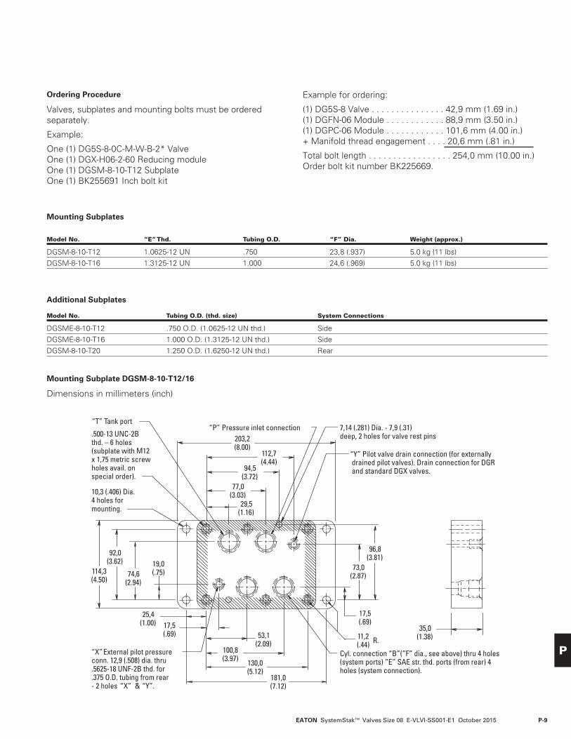
Mounting Subplate DGSM-8-10-T12/16
Dimensions in millimeters (inch)
Model No. “E” Thd. Tubing O.D. “F” Dia. Weight (approx.)
DGSM-8-10-T12 1.0625-12 UN .750 23,8 (.937) 5.0 kg (11 lbs)DGSM-8-10-T16 1.3125-12 UN 1.000 24,6 (.969) 5.0 kg (11 lbs)
Model No. Tubing O.D. (thd. size) System Connections
DGSME-8-10-T12 .750 O.D. (1.0625-12 UN thd.) SideDGSME-8-10-T16 1.000 O.D. (1.3125-12 UN thd.) SideDGSM-8-10-T20 1.250 O.D. (1.6250-12 UN thd.) Rear
“Y” Pilot valve drain connection (for externally
“P” Pressure inlet connection“T” Tank port
(system ports) ”E” SAE str. thd. ports (from rear) 4Cyl. connection “B”(”F” dia., see above) thru 4 holes
203,2(8.00)
35,0(1.38)
114,3(4.50)
92,0(3.62)
74,6(2.94)
112,7(4.44)
77,0(3.03)
29,5(1.16)
19,0(.75)
181,0(7.12)
130,0(5.12)
100,8(3.97)
53,1(2.09)
17,5(.69)
25,4(1.00)
94,5(3.72)
96,8(3.81)
73,0(2.87)
17,5(.69)
11,2(.44) R.
10,3 (.406) Dia. 4 holes formounting.
7,14 (.281) Dia. - 7,9 (.31) deep, 2 holes for valve rest pins
drained pilot valves). Drain connection for DGRand standard DGX valves.
holes (system connection).
.500-13 UNC-2Bthd. – 6 holes(subplate with M12x 1,75 metric screwholes avail. onspecial order).
External pilot pressureconn. 12,9 (.508) dia. thru.5625-18 UNF-2B thd. for.375 O.D. tubing from rear- 2 holes “X” & “Y”.
“X”

© 2015 EatonAll Rights ReservedPrinted in USADocument No.: E-VLVI-SS001-E1 October 2015
Eaton Hydraulics Business USA14615 Lone Oak RoadEden Prairie, MN 55344USATel: 952-937-9800Fax: 952-294-7722www.eaton.com/hydraulics
EatonHydraulics Business EuropeRoute de la Longeraie 71110 MorgesSwitzerlandTel: +41 (0) 21 811 4600Fax: +41 (0) 21 811 4601
EatonHydraulics Group Asia PacificEaton Building4th Floor, No. 3 Lane 280 Linhong Rd. Changning DistrictShanghai 200335ChinaTel: (+86 21) 5200 0099Fax: (+86 21) 5200 0400