Embed Size (px)
Citation preview
LRH 100Piling Rig
LRH 3001.05
EN
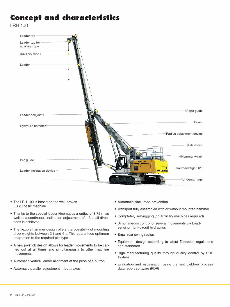
Concept and characteristics LRH 100
• The LRH 100 is based on the well-proven LB 20 basic machine
• Thanks to the special leader kinematics a radius of 8.75 m as well as a continuous inclination adjustment of 1:3 in all direc-tions is achieved
• The flexible hammer design offers the possibility of mounting drop weights between 3 t and 6 t. This guarantees optimum adaptation to the required pile type
• A new joystick design allows for leader movements to be car-ried out at all times and simultaneously to other machine movements
• Automatic vertical leader alignment at the push of a button
• Automatic parallel adjustment in both axes
• Automatic slack rope prevention
• Transport fully assembled with or without mounted hammer
• Completely self-rigging (no auxiliary machines required)
• Simultaneous control of several movements via Load- sensing multi-circuit hydraulics
• Small rear swing radius
• Equipment design according to latest European regulations and standards
• High manufacturing quality through quality control by PDE system
• Evaluation and visualisation using the new Liebherr process data report software (PDR)
Hydraulic hammer
Leader inclination device
Leader top for auxiliary rope
Leader
Leader ball joint
Pile guide
Undercarriage
Hammer winch
Radius adjustment device
Pile winch
Rope guide
Leader top
Auxiliary rope
Boom
Counterweight 12 t
2 LRH 100 – 3001.05
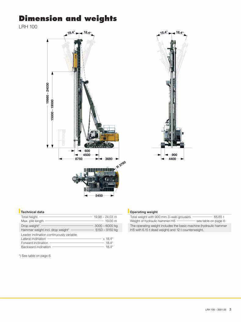
Dimension and weights LRH 100
1998
0 -
2403
0
6004500
8750 3680
5450
9004400
R 3760
18.4° 18.4° 18.4° 18.4°
1500
0 -
1900
0
Operating weight
Total weight with 900 mm 3–web grousers 65.65 t Weight of hydraulic hammer H 6 see table on page 6
The operating weight includes the basic machine (hydraulic hammer H 6 with 6.15 t dead weight) and 12 t counterweight.
Technical data
Total height 19.98 – 24.03 m Max. pile length 19.00 m
Drop weight* 3000 – 6000 kg Hammer weight incl. drop weight* 6150 – 9150 kg
Leader inclination continuously variable Lateral inclination ± 18.4° Forward inclination 18.4° Backward inclination 18.4°
*) See table on page 6.
LRH 100 – 3001.05 3
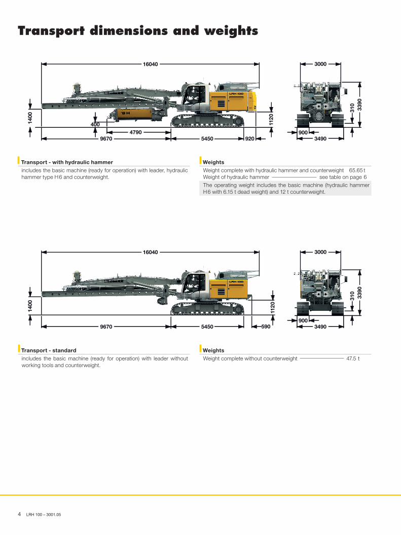
Transport dimensions and weights
4 LRH 100 – 3001.05
1400
16040
92054509670
4004790
1120
3000
3490900
3390
310
Transport - with hydraulic hammer
includes the basic machine (ready for operation) with leader, hydraulic hammer type H 6 and counterweight.
Weights
Weight complete with hydraulic hammer and counterweight 65.65 t Weight of hydraulic hammer see table on page 6
The operating weight includes the basic machine (hydraulic hammer H 6 with 6.15 t dead weight) and 12 t counterweight.
Transport - standard
includes the basic machine (ready for operation) with leader without working tools and counterweight.
Weights
Weight complete without counterweight 47.5 t
1400
16040
59054509670
1120
3000
3490900
3390
310
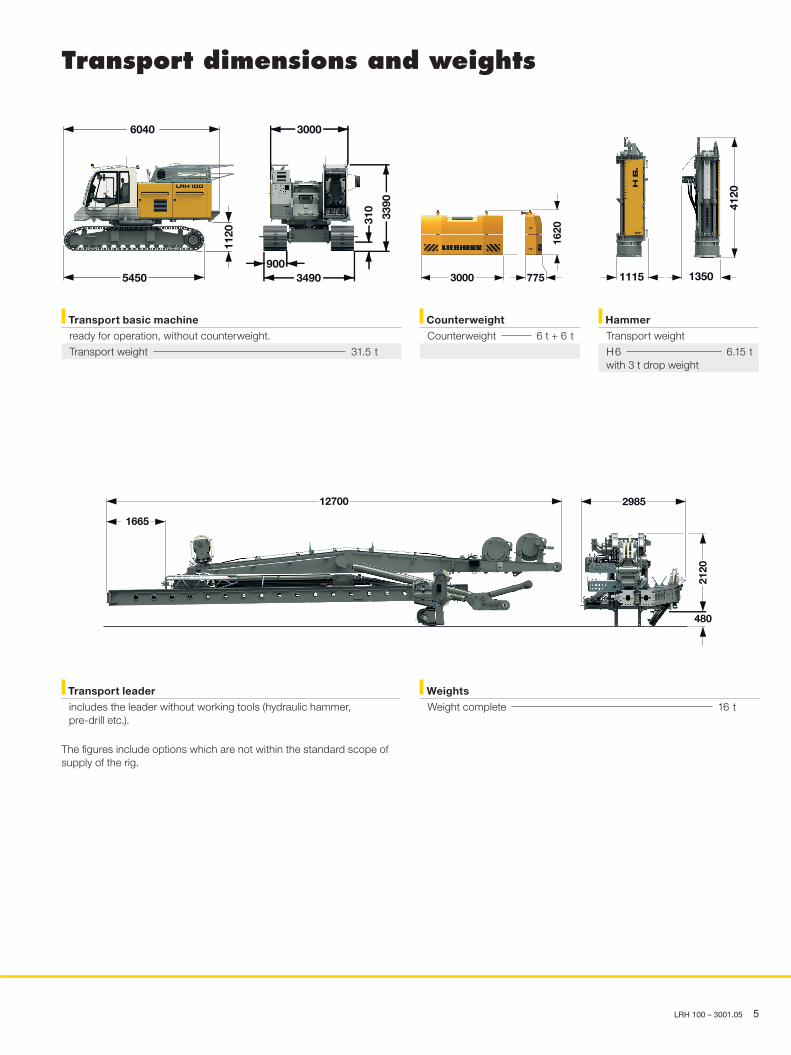
Transport dimensions and weights
LRH 100 – 3001.05 5
Transport basic machine
ready for operation, without counterweight.
Transport weight 31.5 t
Counterweight
Counterweight 6 t + 6 t
3000
3490900
310
5450
6040
1120
3390
3000 775
1620
4120
1115 1350
Hammer
Transport weight
H 6 6.15 twith 3 t drop weight
12700
1665
2985
2120
480
Weights
Weight complete 16 t
Transport leader
includes the leader without working tools (hydraulic hammer, pre-drill etc.).
The figures include options which are not within the standard scope of supply of the rig.
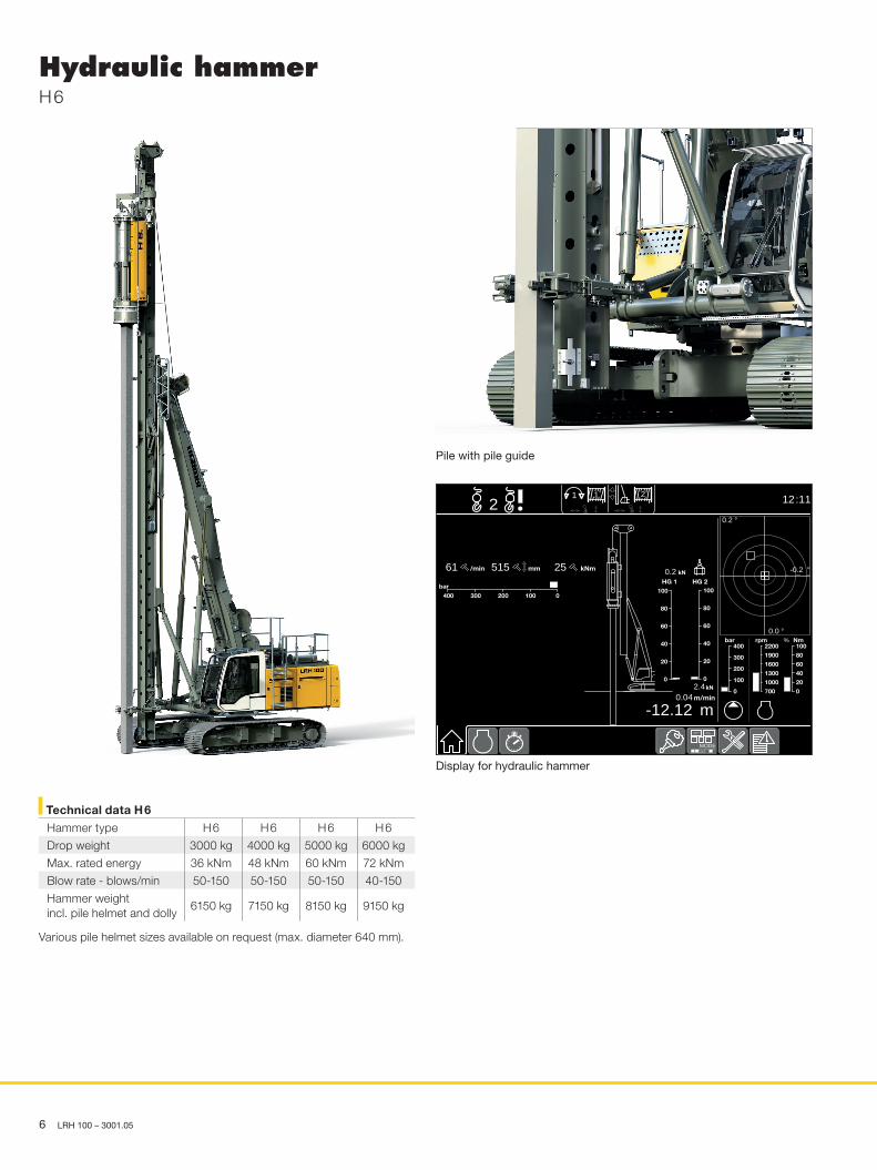
Hydraulic hammer H 6
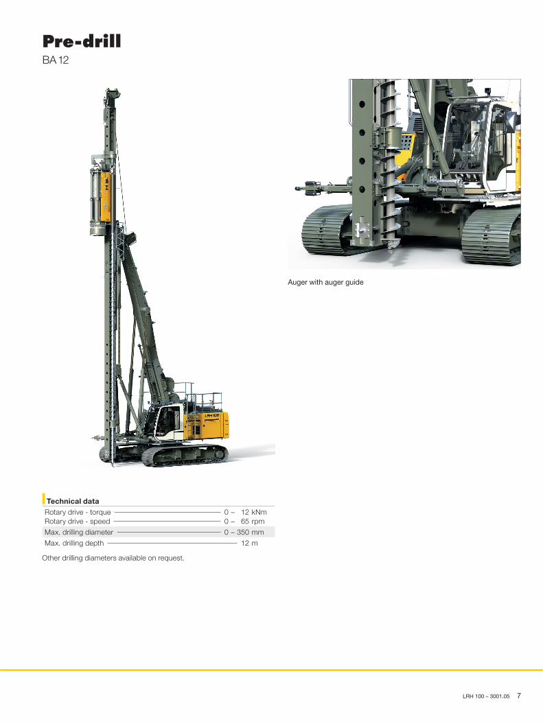
Pile with pile guide
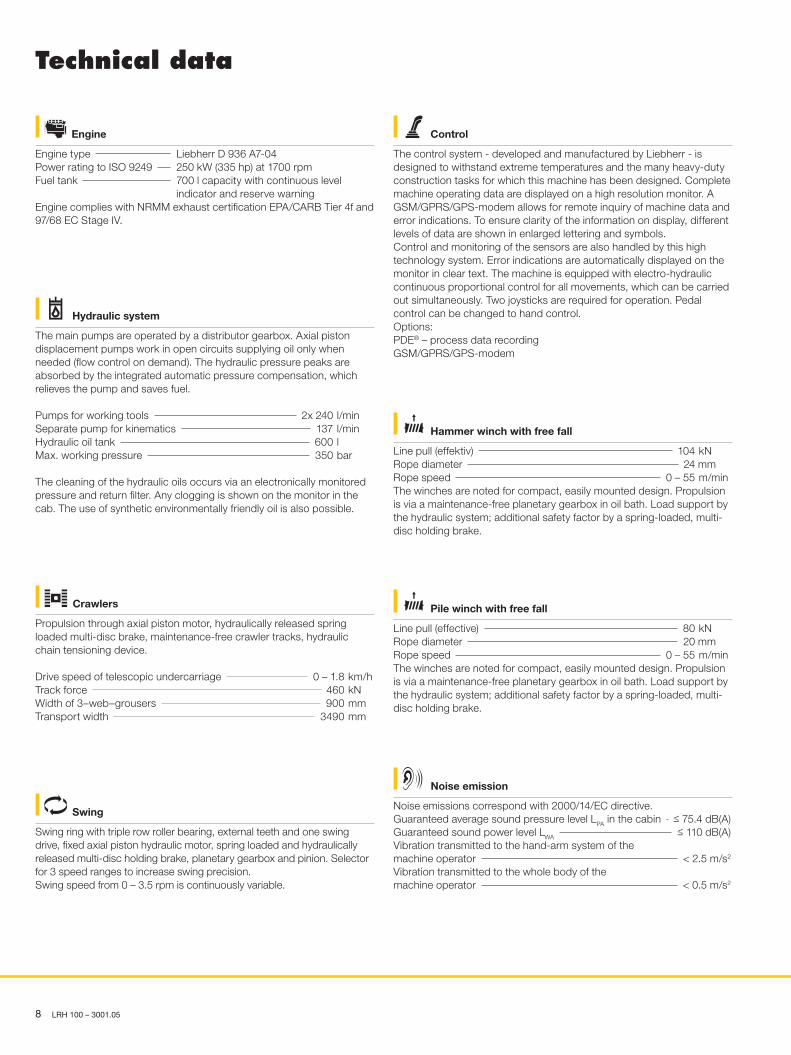
Display for hydraulic hammer
Various pile helmet sizes available on request (max. diameter 640 mm).
Technical data H 6
Hammer type H 6 H 6 H 6 H 6
Drop weight 3000 kg 4000 kg 5000 kg 6000 kg
Max. rated energy 36 kNm 48 kNm 60 kNm 72 kNm
Blow rate - blows/min 50-150 50-150 50-150 40-150
Hammer weight incl. pile helmet and dolly
6150 kg 7150 kg 8150 kg 9150 kg
12:1121 21
MODE
700
1000
1300
1600
1900
2200rpm
0
20
40
60
80
100Nm%
0
20
40
60
80
100
0
20
40
60
80
100HG 1 HG 2
2.4kN
0.2 kN
-12.12 m0.04m/min
0
100
200
300
400bar
0100200300400
bar
/min61 mm 25 kNm515
0.0 °
°-0.2
0.2 °
6 LRH 100 – 3001.05
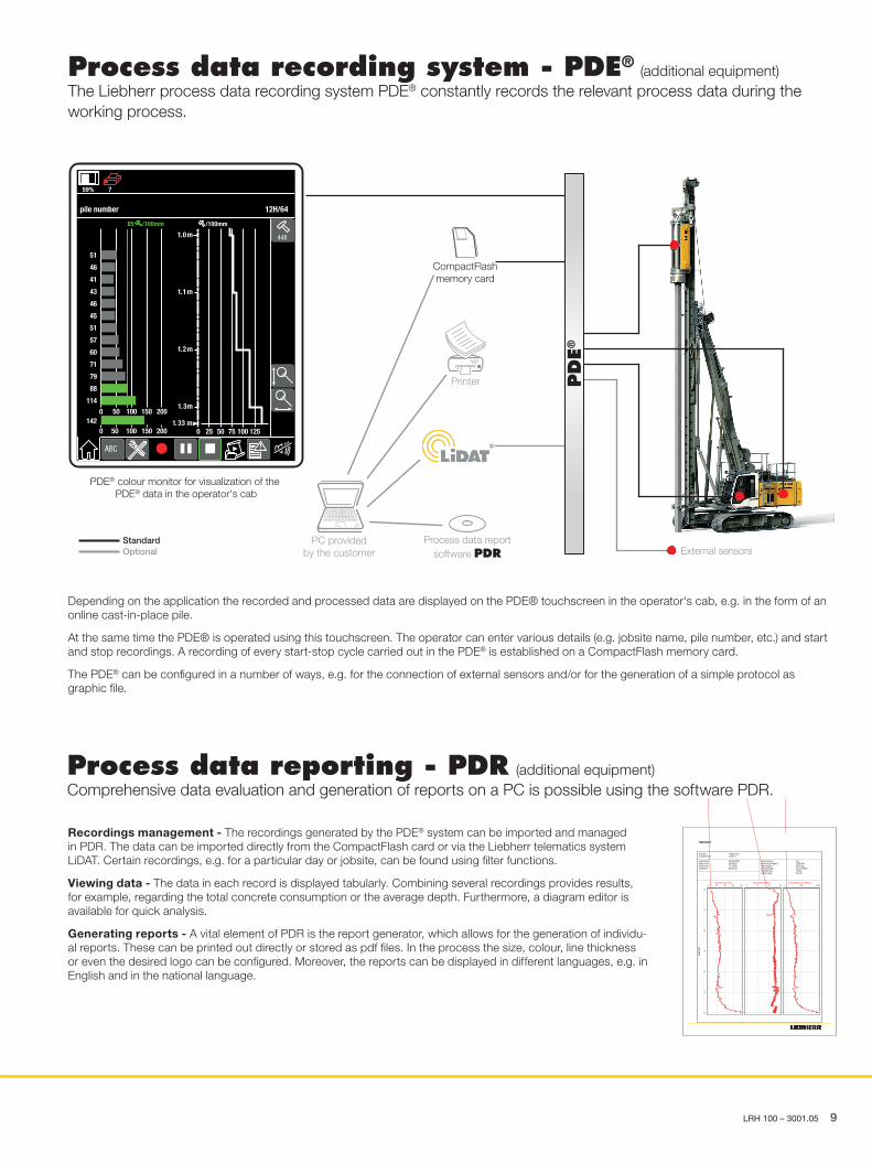
Pre-drill BA 12
Auger with auger guide
Other drilling diameters available on request.
Technical data
Rotary drive - torque 0 – 12 kNm Rotary drive - speed 0 – 65 rpm
Max. drilling diameter 0 – 350 mm
Max. drilling depth 12 m
LRH 100 – 3001.05 7
Technical data
Control
The control system - developed and manufactured by Liebherr - is designed to withstand extreme temperatures and the many heavy-duty construction tasks for which this machine has been designed. Complete machine operating data are displayed on a high resolution monitor. A GSM/GPRS/GPS-modem allows for remote inquiry of machine data and error indications. To ensure clarity of the information on display, different levels of data are shown in enlarged lettering and symbols. Control and monitoring of the sensors are also handled by this high technology system. Error indications are automatically displayed on the monitor in clear text. The machine is equipped with electro-hydraulic continuous proportional control for all movements, which can be carried out simultaneously. Two joysticks are required for operation. Pedal control can be changed to hand control.Options: PDE® – process data recordingGSM/GPRS/GPS-modem
Hammer winch with free fall
Line pull (effektiv) 104 kNRope diameter 24 mm Rope speed 0 – 55 m/minThe winches are noted for compact, easily mounted design. Propulsion is via a maintenance-free planetary gearbox in oil bath. Load support by the hydraulic system; additional safety factor by a spring-loaded, multi-disc holding brake.
Pile winch with free fall
Line pull (effective) 80 kNRope diameter 20 mm Rope speed 0 – 55 m/minThe winches are noted for compact, easily mounted design. Propulsion is via a maintenance-free planetary gearbox in oil bath. Load support by the hydraulic system; additional safety factor by a spring-loaded, multi-disc holding brake.
Crawlers
Propulsion through axial piston motor, hydraulically released spring loaded multi-disc brake, maintenance-free crawler tracks, hydraulic chain tensioning device.
Drive speed of telescopic undercarriage 0 – 1.8 km/h Track force 460 kNWidth of 3–web–grousers 900 mmTransport width 3490 mm
Engine
Engine type Liebherr D 936 A7-04 Power rating to ISO 9249 250 kW (335 hp) at 1700 rpm Fuel tank 700 l capacity with continuous level indicator and reserve warningEngine complies with NRMM exhaust certification EPA/CARB Tier 4f and 97/68 EC Stage IV.
Hydraulic system
The main pumps are operated by a distributor gearbox. Axial piston displacement pumps work in open circuits supplying oil only when needed (flow control on demand). The hydraulic pressure peaks are absorbed by the integrated automatic pressure compensation, which relieves the pump and saves fuel.
Pumps for working tools 2x 240 l/min Separate pump for kinematics 137 l/min Hydraulic oil tank 600 l Max. working pressure 350 bar
The cleaning of the hydraulic oils occurs via an electronically monitored pressure and return filter. Any clogging is shown on the monitor in the cab. The use of synthetic environmentally friendly oil is also possible.
Swing
Swing ring with triple row roller bearing, external teeth and one swing drive, fixed axial piston hydraulic motor, spring loaded and hydraulically released multi-disc holding brake, planetary gearbox and pinion. Selector for 3 speed ranges to increase swing precision.Swing speed from 0 – 3.5 rpm is continuously variable.
Noise emission
Noise emissions correspond with 2000/14/EC directive. Guaranteed average sound pressure level LPA in the cabin ≤ 75.4 dB(A)Guaranteed sound power level LWA ≤ 110 dB(A)Vibration transmitted to the hand-arm system of the machine operator < 2.5 m/s2
Vibration transmitted to the whole body of the machine operator < 0.5 m/s2
8 LRH 100 – 3001.05
Process data reporting - PDR (additional equipment) Comprehensive data evaluation and generation of reports on a PC is possible using the software PDR.
Depending on the application the recorded and processed data are displayed on the PDE® touchscreen in the operator‘s cab, e.g. in the form of an online cast-in-place pile. At the same time the PDE® is operated using this touchscreen. The operator can enter various details (e.g. jobsite name, pile number, etc.) and start and stop recordings. A recording of every start-stop cycle carried out in the PDE® is established on a CompactFlash memory card.
The PDE® can be configured in a number of ways, e.g. for the connection of external sensors and/or for the generation of a simple protocol as graphic file.
Process data recording system - PDE® (additional equipment)
The Liebherr process data recording system PDE® constantly records the relevant process data during the working process.
Recordings management - The recordings generated by the PDE® system can be imported and managed in PDR. The data can be imported directly from the CompactFlash card or via the Liebherr telematics system LiDAT. Certain recordings, e.g. for a particular day or jobsite, can be found using filter functions. Viewing data - The data in each record is displayed tabularly. Combining several recordings provides results, for example, regarding the total concrete consumption or the average depth. Furthermore, a diagram editor is available for quick analysis. Generating reports - A vital element of PDR is the report generator, which allows for the generation of individu-al reports. These can be printed out directly or stored as pdf files. In the process the size, colour, line thickness or even the desired logo can be configured. Moreover, the reports can be displayed in different languages, e.g. in English and in the national language.
job site:machine ID:
start date:
stop time:start time:
duration:
23.09.200916:45:1217:19:5600:34:44
<Naturum1151xx
hammer
pile number:maximum depth:ram weight:total energy:total blows:depth step:
192200 cm6000 kg18774 kNm
6 0 5 110 cm
dept
h [m
]
22
21
20
19
18
17
16
blow s/depth step v806040200
energy/blow [kNm ] v151050
energy/depth step [kNm ] v1 0005000
PDE® colour monitor for visualization of the PDE® data in the operator's cab
Process data reportsoftware PDR
PC providedby the customer
CompactFlashmemory card
External sensors
Printer
StandardOptional
PDE®
pile number 12H/64
0 25 50 75 100 12533.1 m
/100mm
2.1 m
1.1 m
0.1 m
3.1 m
0 50 100 150 200
0 50 100 150 200
51
46
41
43
46
45
51
57
60
71
79
88
114
142
85 /100mm
ABC
59% 7
448
LRH 100 – 3001.05 9
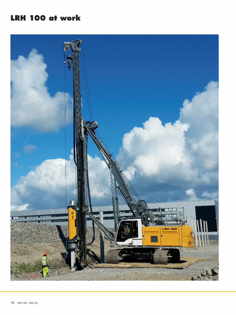
LRH 100 at work
10 LRH 100 – 3001.05
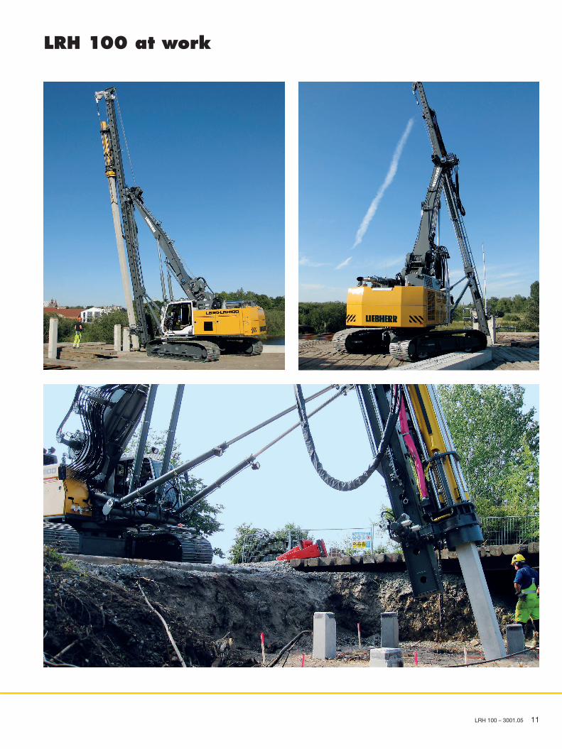
LRH 100 at work
LRH 100 – 3001.05 11

LRH
100
– 10
5381
48 –
Ver
sion
03
– 02
/201
8 Su
bjec
t to
chan
ge w
ithou
t not
ice.
Liebherr-Werk Nenzing GmbH Dr. Hans Liebherr Str. 1, 6710 Nenzing/Austria Tel.: +43 50809 41–473, Fax: +43 50809 41–499 [email protected], www.liebherr.com facebook.com/LiebherrConstruction


![HYDRAULIC PILING RIG - Piling Contractors · Forward | Backward | Lateral Avanti | Indietro | Laterale 3° | 15° | ±3 WEIGHT ... Tiro nominale al 1° strato pull on 1st layer [kN]](https://img.pdfslide.us/doc/110x75/5ae7d6ae7f8b9a9e5d8fb0d4/hydraulic-piling-rig-piling-backward-lateral-avanti-indietro-laterale.jpg)