Embed Size (px)
Citation preview
REPAIR, EVALUATION, MAINTENANCE, AND REHABILITATION RESEARCH PROGRAM
TECHNICAL REPORT REMR-GT-4
STATE f'l;'~ t IF" ART FOR nrsiGN U1 : :r:: Jc J.\ND CONSTRUCTION OF SAND
COMPACTIOr~ PILES
by
Richard D. Barksdale
School of Civil Engineering Georgia Institute of Technology
At1<-'"' ,1:;, Georgia 30332
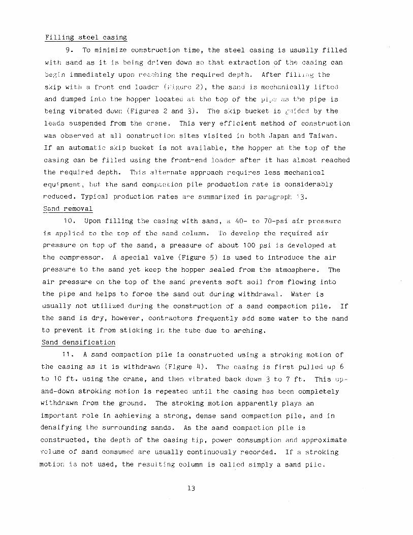
November 1987
Final Report
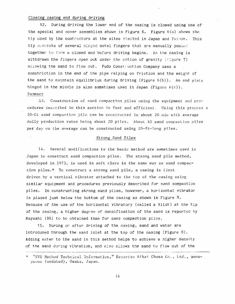
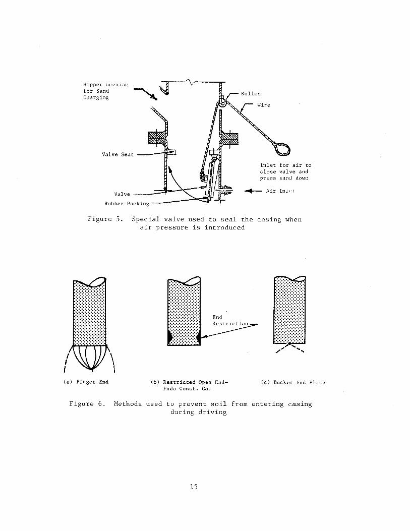
Approved For Public Release, Distribution Unlimited
Prepared tor DEPARTMENT OF THE ARMY US Army Corps of Engineers Washington, DC 20314-1000
under Civil Works Research Work Unit 32275 Monitored by Geotechnical Laboratory
US Army Engineer Waterways Experiment Station PO Box 631, Vicksburg, Mississippi 39180-0631
The following two letters used as part of the number designating technical reports of research published under the Repair, Evaluation, Maintenance, and Rehabilitation (REMR) Research Program identify the problem area under which the report was prepared:
Problem Area Problem Area
CS Concrete and Steel Structures EM Electrical and r,~Gchanical
GT Geotechnical El Environmental lmpLc
HY Hydraulics 0~/ Operations Management
CO Coastal
For example, Technical Report REMR-GT -4 is the fourth report published under the Geotechnical problem area.
COVER PHOTOS:
Destroy this report when no longer needed. Do not return it to the originator.
The findings in this report are not to be construed as an official Department of the Army position unless so designated
by other authorized documents.
The contents of this report are not to be used for advertising, publication, or promotional purposes. Citation of trade names does not constitute an official endorsement or approval of the use of such commercial products.
TOP- Typical S<'.nd Compaction Pile Construction Equipment.
BOTTOM- Typical Equipment Used To Construct Mammoth Compaction Poles Over Water.
Unclassified SECUHITY CLASSIFICATION OF THIS PAGE r-----"
REPORT DOCUMENTATION PAGE OMBNo 0704·0188 I Form Approved
Exp. Date fun 30, 1986 "'".
1a. REPORT SECURITY CLASSIFICATION 11 b. RESTRICTIVE MARKINGS
JlD(;;la:l:l1fh:sl 2a. SECURITY CLASSIFICATION AUTHORITY 3 DISTRIBUTION I AVAILABILITY OF REPORT
2b DECL/1 SSIFICA TION I DOWNGRADING 'scHEDULE Approved for public release; distribution unlimited
4. PERFORMING ORGANIZATION REPORT NUMBER(S} 5. MONITORING ORGANIZATION REPORT NUMBER($}
Technical Report REMR-GT-4 6a. NAME OF PERFORMING ORGANIZATION 6b. OFFICE SYMBOL 7a. NAME OF MONITORING ORGANIZATION
(If applicable) USAEWES Georgia Institute of Technology Geotechnical Laboratory 6c ADDRESS (City, State, and ZIP Code) lb. ADDRESS (City, State, and ZIP Code)
PO Box 631 Atlanta, GA 30332 Vicksburg, MS 39180--0631 8a. NAME OF FUNDING I SPONSORING Bb. OFFICE SYMBOL 9. PROCUREMENT INSTRUMENT IDENTIFICATION NUMBER
ORGANIZATION (If applicable)
US Army Corps of Engineers DACW39-85-M-2358 Be. ADDRESS (City, State, and ZIP Code) 10. SOURCE OF FUNDING NUMBERS
PROGRAM PROJECT TASK WORK UNIT ELEMENT NO. NO NO. ACCESSION NO
Washington, DC 20314-1000 32275
11. TITLE (Include Security Classification)
State of the Art for Design and Construction of Sand Compaction Piles
12. PERSONAL AUTHOR($)
Barksdale, Richard D. 13a. TYPE OF REPORT r3b. TIME COVERED 14. DATE OF REPORT (Year, Month, Day) rs PAGE COUNT
Final report FROM TO November 1987 57 16. SUPPLEMENTARY NOTATION A report of the Geotechnical problem area of the Repair, Evaluation, Maintenance and Rehabilitation (REMR) Research Program. This report is available from the National Technical Information Service, 5285 Port Royal Road, Springfield, VA 22161. 17. COSATI CODES 1B. SUBJECT TERMS (Continue on reverse if necessary and identify by block number)
FIELD GROUP SUB-GROUP In-situ deep compaction Remedial treatments Liquefaction Soils Pore-water pressure Pool reinforcement
19. ABSTRACT (Continue on reverse if necessary and identify by block number)
Sand compaction piles can be used to improve marginal sites for stability, liquefac-tion, and settlement applications. They have been employed extensively in Japan for many years to improve land reclaimed from the sea. The advantages and disadvantages of using sand compaction piles are compared with other vibro-compaction techniques such as stone columns. Methods are described for construction of sand compaction piles on land and over water.
Design theories are given for the utilization of sand compaction piles at sites under-lain by both cohesionless and cohesive soils. For sites underlain by cohesionless sands, procedures are presented for estimating the increase in standard penetration resistance in both the sand compaction pile and the surrounding sand. Techniques are described for esti-mating stability and one-dimensional consolidation settlement of sites underlain by cohesive soils that have been improved with sand compaction piles. Finally, typical applications of sand compaction piles are described, and practical design criteria and practices are given.
20. DISTRIBUTION I AVAILABILITY OF ABSTRACT 21 ABSTRACT SECURITY CLASSIFICATION
(RJ UNCLASSIFIED/UNLIMITED 0 SAME AS RPT 0 DTIC USERS Unclassified 22a. NAME OF RESPONSIBLE INDIVIDUAL 22b TELEPHONE (Include Area Code) 22c. OFFICE SYMBOL
DO FORM 1473, 84 MAR B3 APR ed1t1on may be used until exhausted
All other ed1t;ons are obsolete SECURITY CLASSIFICATION OF THIS PAGE
Unclassified
J
PREFACE
The original research for this report was performed for the US Depart
ment of Transportation, Federal Highway Administration, under a contract to
the School of Civil Engineering, Geu1 i~ Tnstitute of Technclogy. The final
re~nrt presented herein was prepared under Contract No. DACW39-85-M-2358 with
the US Army Engineer Waterways Experiment Station (WES) during the period
July 1985 to December 1986. The investigation was conducted under the Repair,
Evaluation, Maintenance, and Rehabilitation (REMR) Research Program Work
Unit 32275, "Remedial Improvement of Liquefiable Foundations." Mr. Authur H.
Walz, Headquarters, US Army Corps of Engineers (HQUSACE), was REMR Technical
Monitor.
The REMR Overview Committee, consisted of Mr. John R. Nikel
(DAEN-C\.-70-M), Mr. Bruce L. McCartney (DAEN-CWH-D), and Dr. Tony C. Liu
(DAEN-ECE-D). Coordinator for the Directorate of Research and Development
was Mr. Jesse A. Pfeiffer, Jr. (DAEN-RDC), and the REMR Program Manager
was Mr. William F. McCleese, Concrete Technology Division, Structures
Laboratory, WES
Appreciation is expressed to the Federal Highway Administration for grant
ing special permission to allow the publishing of this report. Mr. A. F.
DiMillio was project manager, and Mr. Jerry DiMaggio was Technical Monitor for
the Federal Highway Administration. Mr. Richard H. Ledbetter, Earthquake
Engineering and Geophysics Division (EEGD), Geotechnical Laboratory (GL), was
Technical Monitor for the WES, under the supervision of Dr. Arley G. Franklin,
Chief, EEGD, and under the general supervision of Dr. William F. Marcuson III,
Chief, GL. Appreciation is extended for Mr. Ledbetter's help and careful
review of the manuscript. Special thanks also go to Dr. P. F. Hadala, Assis
tant Chief, GL, for his thorough review of the manuscript.
The contents of this report reflect the views of the author who is
responsible for the facts and accuracy of the data presented herein. The
contents do not necessarily reflect the official view or policies of the US
Army Engineer Waterways Experiment Station. This report does not constitute
a standard, specification, or regulation.
The design and construction practices for sand compaction piles described
in this report are felt to be representative of those presently followed in
Japan. These practices, as described, were developed from discussions with
1
Japanese and Taiwanese engineers, contractors, and equipment manufacturers
along with field inspections and a review of the literature. Thanks are given
to all the engineers and organizations, too numerous to acknowledge separately,
who made ,.;,luable contributions to this study. Special acknowledgement is
given to Mr. Tony Sullivan of Kencho, Inc. and Mr. Mizutani of Kensetsu Kikai
Clwsa Co., Ltd. for Jl!aking detailed arrangements for the inspection trip to
Japan and Taiwan.
COL Dwayne G. Lee, CE, is Commander and Director of WES. Dr. Robert W.
Whalin is Technical Director.
2
CONTENTS
Page
PREFACE.................................................................. 1
CONVERSION FACTORS, NON-SI TO Sl (HETRIC) UNITS OF HEASUREMENT........... 4
PART I: INTRODUCTION.................................................... 5
Advantages and Disadvantages of Sand Compaction Piles............... 5 Sand Compaction Piles in Japan...................................... 7
PART II: CONSTRUCTION OF SAND PILES..................................... 9
Sand Compaction Pile Construction................................... 9 Strong Sand Piles................................................... 14 Mammoth Compaction Piles ..............•..•..... ,.................... 17 General Considerations... . . . . . . . . . . . . . . . • • . . . • . . . . . . . . . . . . . . . . . . . . . . 17
PART III: DESIGN THEORY FOR SAND COMPACTION PILES ....................... 20
Introduction... . . . . . . . . . . . . . . . . . . . . . . . . • . . . . . . . . . . . . . . . . . . . . . . . . . . . . 20 Area-Replacement Ratio... . . . . . . . . • . . . . • . . . . . . . . . . . . . . . . . . . . . . . . . . . . . 20 Sites Underlain by Sand............................................. 21 Sites Underlain by Cohesive Soils ..............•.................... 30 Increase in Shear Strength Due to Consolidation .....•..........•.... 33 Conclusions. . . . . . . . . . . . . . . . . . . . . . . . . . . . . . . . . . . . . . . . . . . . . . . . . . . . . . . . . 35
PART IV: GENERAL DESIGN CONSIDERATIONS ........•......................... 37
Applications. . . . . . . . . . . . . . . . . . . . . . . . . . • . . . . . . . . . . . . • . . . . . . . . . . . . . . . . 37 General Criteria and Practices ......................•...........•... 40 Stability Considerations ............................................ 40 Stress Concentration................................................ 44 Sand Pile Gradation................................................. 45 Quality Control..................................................... 45 Influence of Lateral Pressure on SPT Value. . . . . . . . . . . . . . . . . . . . . . . . . . 50 Strength Loss Due to Sand Pile Installation ......................... 50
PART V: SUMHARY AND CONCLUSIONS......................................... 52
REFERENCES. . . . . . . . . . . . . . . . • . . . . . . . . . . . . . . . . • . . . . . . • . . . . . . . . . . . . . . . . . . . . . . 54
3
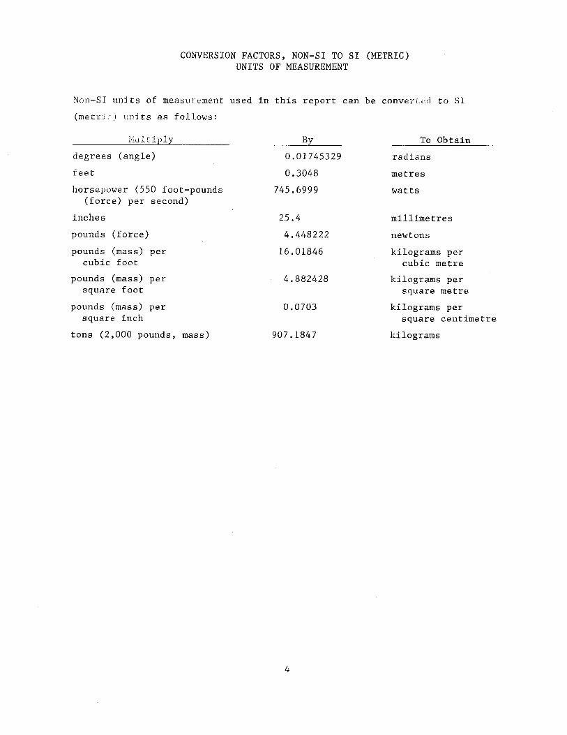
CONVERSION FACTORS, NON-SI TO SI (METRIC) UNITS OF MEASUREMENT
Non-SI units of measurement used in this report can be converi;.:d to SI
(metri~) units as follows:
i'·'lultiply
degrees (angle)
feet
horsepower (550 foot-pounds (force) per second)
inches
pounds (force)
pounds (mass) per cubic foot
pounds (mass) per square foot
pounds (mass) per square inch
tons (2,000 pounds, mass)
By
0.01745329
0.3048
745.6999
25.4
4.448222
16.01846
4.882428
0.0703
907.1847
4
To Obtain
radians
metres
watts
millimetres
newtons
kilograms per cubic metre
kilograms per square metre
kilograms per square centimetre
kilograms
STATE OF THE ART FOR DESIGN AND CONSTRUCTION OF
SAND COMPACTION PILES
PART I: INTRODUCTION
1. Sand compaction piles are one potential method for improving
marginal sites for stability, liquefaction and settlement applications.
They also act as drains for static loading and accelerate primary
consolidation. Sand compaction piles have been used extensively in Japan
and Taiwan primarily for stability purposes in reclaiming land from the sea.
Sand piles are similar to sand compaction piles but are not densified to as
high a degree. Sand piles have been used in the United States primarily
for sand drains to accelerate consolidation settlement but in recent years
have been generally replaced by wick drains. Sand compaction piles, as
defined in this report, have apparently not been used in the United States.
Advantages and Disadvantages of Sand Compaction Piles
2. Table 1 summarizes the advantages and disadvantages of sand
compaction piles compared with several types of stone columns. The primary
advantages of sand compaction piles over stone columns are (a) sand, which
is often considerably cheaper than stone, is used in construction, (b)
construction of the sand column is extremely fast, (c) the hole is fully
supported by a casing during construction that eliminates the possibility
of hole collapse, and (d) the possibility of intrusion and/or erosion of
surrounding soil into the sand column is significantly reduced compared with
stone columns; whether movement of particles can occur depends upon the
gradation of both the sand compaction pile and the surrounding soil. Sand
compaction piles are a possible solution for strengthening pervious
embankment foundations found to be susceptible to liquefaction or
impervious foundations susceptible to stability problems, for example,
during an earthquake.
3. Sand compaction piles also have several important disadvantages
that rnust be carefully considered during design The primary
disadvantages of sand compactiun piles are: (a) they have a lower angl0 of
5
0\
Unca•ed Role ConstructionStone Colu••
Caoed Role Conatructton
Table 1
Summary of Applications, Advantages, and Disadvantages of Selected
Vibro-Ground Reinforcement Techniques
IIETHOO
Vtbro-replBceiN!nt (...,t)
Vibt~ditplacetlent (dry)Ul
Ri&id Concrete Colu..,(l)
APPLICATIONS
Very soft to flrta cohesive soils()) ISO S c S. 1500 psf; Silty sands ('•IS% fines); 11ethod ueed for most stability settlement, liquefaction applications
Partte~lly saturat~d cohesive soils; 400 ~ c S 1000 psf(J); use where environiiK'!ntal restrictions exclude Yibro-rephcernent; use in partiAlly saturated clay fills; stability, settte•nt and ltquehction applications
Cohesive erih with 100 pef < c S 800 pefO• ) ; tooee to fir• ;ilty sande and eilta; uae where peat ta present; use in weak eoU, c S 300 pllf; stability and aettlii!'~Rnt application•
ADVANTAGES
Cmwentional Method; Ho'!"e pol'litivc hole support than dry me tho(;: less hole smear than other methods: hi.gh k may allow u dissipation durinR earthquake; typical 20-60 tons design capacity; hi~her capacity in silty sands.
No silty water to dispoae: aay bf! slightly c:hll!'aper than wet (stMller dia.); 15-t.O ton desip;n
No sll ty \tater dispoul proble• H dry; Good in or8anic: soils And peat; Fully surported hole; sNll eettle.ent: about the same coat as conventional stone colu~m; hat; hifth load capacity up to 40-80 tons
DISADVANTAGES
Some uncertainty existn concerning support of hole in very soft to soft soi h; not suitable in peat layers > ! column dia.; ftiUSt usl" ll'lrge stone which 1MY be expens;ve; !l'l.lSt dispose of silty effluent; :10t suitable if sensitivity ..,. 6; ir-truslon miRht occur-.
SIMller loo!l:d ':.apaclt~· and dta. th~n vet method; ibdted to partially saturated~ b@!tter soils which "'ill not collap8e; lklre a-.ear than wet method
Coluwa does not act as drain; for stability applications ~valuate local besrin8 failure of soft l!loil behind colu~m using lateral Jo~·i t~st; ColuWI .,re brittle thn; conventional stone colu~m; Use a R<l3lnular distribution blanket .&nd fabric above colu~ma; f<'r e:tabil ity support entire ellbankTWnt to prevent larr.r bendintt IIDWM!nt~ i_n pile
~--------~----------------~r-----------------;-------·-----------Stone Co.,acUon ruoU>
Sand C~ac t ion ru.(2>
Cohedve •oils with 200 paf ~ c ~ 800 psf(4); very loose to fir• silty unda, Jll s lS; stability, settlewnt and liquefaction aprlications
Sands. dlty sandat cohesive soils with e ) 100 psf; use prhwrily fur stability and tank/stockpile type appl icationa; liquefaction
Nl., •ilty water disposal preble•; fully supported hole; fast; can uae finer ~udation in very soft soils to prevent tntrudon; 15-40 tons
No !'JJ l ty water disposal problll!'•: !lo1e fully supported; uses ch~ap, local sand; very soft soli will not penetrate co1un1; Method is very fast; accehrates consolidation settle~~~ent; l:S-JS tons
S-.ller dla. th11n vibro-replacement colu.n: SN!'Rr froa advancing casing gives lovll!'r horizontal perlllel'!b1B~;· than stonlf! c:olu•; auat use sp~d.ltl bottoa-ff~ed riR; Dta. st<."n(' -S 1.5 in.
Smear fr~ advancing casin<-; reduce~ horizontal per.eabil ity; ·! not dissipated during earthqur 1~.e; consider local bearing f.oo:Hur'!': in very soft sotJe(S); -.ore t':!:ttl~ment and lrwf'r strenRth th~n r>tone coluMn
Note•: 1. A pull-down type rig h used to construct rlRld concrete colu~~~ns, stone cot~pactlon ptle~ and sand co~npactton piles; vibro-disptac~aen::: (dry) colu-.s can also be con11tructed vith a pull-down rig.
2. Sand c0111paction pile11 can be constructed using a puJl-dovn type riJt, by rannin~ or the Japanese ~~ethod using a hollow pile vith 1.1 vibrator at the top.
3. P1'edr1111ns aay be used to advance hole in stiff soils with c > 1000 pef.
4. The •lbrator can be run vet (vlth water jets operating) and penetrate to 1000 psf soil.
5. Local bear in@; failure in very soft soils is leas or a problea for und cow.pact1on piles (which carry Jess total load than stone colu.,e).
internal friction and a lower stiffness than stone columns; hence in
general a larger percentage replacement of weak soil is required using sand compaction piles; (b) driving the casing through a clay layer causes
"smear" along the boundary of the column that reduces lateral r•rmeability and i1ence their effecti vcn·:'ss as a drain. Nevertheless, an important decrease in time for primary consolidation occurs when sand compaction piles are used, and (c) sand compaction piles do not have sufficiently high
permeability to function as effective vertical drains during earthquakes. Use of a sand compaction pile would increase the relative density of pervious native soils between the piles, the amount of improvement
depending upon the pile spacing, method of construction and other factors.
Also the strength of the sand compaction pile would increase the resistance to failure should liquefaction occur.
Sand Compaction Piles in Japan
4. The need in Japan to reclaim extensive areas from the sea lead to
the first construction of sand piles between 1830 and 1850 (Ichimoto, 1980). Early in the 20th century a technique for compacting the sand pile was
developed which was apparently somewhat similar to the process now used for constructing Franki type concrete piles. Today, sand compaction piles are
usually constructed by driving a pipe having a special end restriction through a loose to firm sand, or very soft to firm silt or clay stratum
using a vibrator located at the top of the pipe. Sand compaction piles generally have a diameter varying from 24 to 32 in.,* but may be as large as 80 in. Typically 5- to 7-ft sand compaction pile spacings are used
in Japan. During or immediately after driving, the pipe is filled with sand. The sand is then densified by repeatedly raising and lowering the vibrating pipe as it is withdrawn from the ground. Several modifications of this procedure which can be described in Japanese terminology are
mammoth compaction piles and strong sand piles. Mammoth compaction piles are quite similar to sand compaction piles except they are usually
constructed over water using larger equipment. Strong sand piles are
* A table of factors for converting non-SJ units of measurement to SI (metric) units presented on page 4.
7
installed using the same procedure as for sand compaction piles but are
further densified using a horizontal vibrator at the bottom of the casing.
Sand compaction piles and mammoth compact ion piles are Lhe most commonly
used sand pile tecl:ni.ques in Japan for impr·oving poor sites.
5. 1 n Japan over 1 , ,1uU, 000 ft of sarh: compaction piles and .sand
drains we;, r:nnstructed durin'-~ U1c last 20 years by Fud<.' Construction Co.
alone; undoubtedly this is just a small fraction of the total length
constructed during this time. Probably the greatest use of sand compaction
piles is to improve hydraulic sand fills and/or the underlying weak natural
soils. Sand compaction piles in Japan are used primarily to prevent
stability failur'es, decrease the time of consolidation and prevent
liquefaction failure. Sand compaction piles are also used in Japan to
reduce settlement although this appears usually to be a secondary
since preloading is generally utilized. The distribution of uses of sand
compaction piles by Fudo C6nstruction Company is given in Figure 1 ; this
summary, based on the results of the fact-finding trip, is felt to be
generally representative of the overall use of sand compaction piles in
Japan. Over 80 percent of the sand compaction piles are used to support
stockpiles of heavy materials and various types of tanks and embankments
for roads and railways. Only 4 percent of the sand compaction piles are
used in Japan to support buildings and warehouses. The extent of use in
Japan, if any, of sand compaction piles in dams, locks and levees is not
known.
8
PART II: CONSTRUCTION OF SAND PILES
Sand Compaction Pile Construction
6. The equipment typically used to construct a sand compaction pile
is shown in Figures 2 and 3 and the construction sequence in Figure 4.
For constructing sand compaction piles, a 4.~- to 6-ton hydrauJic or
electric vibrator is attached to the top of a 16- to 24-in. diam ste2l
pipe. The pipe casing is slightly longer than the desired length of the
sand compaction pile so as to protrude out of the ground after reaching the
design depth. The pipe fully supports the surrounding soil at all times
during construction. A description of how native soil is prevented from
entering the pi~e is subsequently dnscribed in paragraph 12. Water jets
are sometimes used on the outside of the pipe when layers are encountered
that have a standard penetration test (SPT) resistance greater than about
15 to 20. Water jet pressures up to 1200 psi have been used to aid
driving piles using vibratory hammers (Hayashi, 1981).
7. The casing with attached vibratory hammer is suspended from a
crawler crane and is guided by leads. A 35- to 40-ton crawler crane is
used for constructing 60- to 65-ft-long sand compaction piles. A coil
spring shock absorber is fastened to the top of the vibrating hammer to
dampen the shock as the casing is pulled from the ground by the crane.
During driving, the cable from the crane to the casing is kept slack so that
the pipe-vibrator assembly is free floating. Proper pipe alignment is
maintained by a guide attached to the vibrator that moves up and down the
crane leads.
8. A low frequency, high amplitude vertical vibrator is used having a
frequency of 500 to 600 cpm and amplitude during idling of 0.6 to 0.7 in.
The amplitude is defined as one-half the total tip movement. The commonly
used vibrators are driven by 120 to 160 hp Inotors and have unbalanced
forces varying from 90,000 to 135,000 lb as summarized in Table 2. Large
vibrators having greater than 120 hp are usually used for only the
construction of mammoth compaction piles over water, described in
paragraph 16.
9
Yards Mills
42.3%
Embankment for Roads and Railways
Foundation of Harbor Structures
Buildings and Warehouses
Figure 1. Distribution of sand compaction pile applications (after "Compozer System," Fudo Construction Co., Ltd., anon
ymous (undated), Tokyo, Japan
Recorder for Power, Sand Volume, Tip Depth
Guide Leads
Spring Shock Absorber
Suspending Wire Vibrator
Hopper
Casing Pipe
Air Line
Power Line
Sand Skip Bucket
Front End Loader
Figure 2. Typical equipment used to construct a sand compaction pile in Japan (after Tanimoto, 1973)
lO
a b
Figure 3. Photograph of typical sand compaction pile construction equipment
used in Japan and Taiwan
Construction Steps
d
Penetration Extraction of Pipe
(a) Installation
Figure 4.
H Completed length of pile per one cycle H
0 Length of cornp~ction process
HE Lengtl1 of extraction process
(b) C~sing Tip ~lovement
Construction sequence for sand compaction piles (after Tanimoto, 1973)
11
f-'
I N
Table 2
Typical Japanese Vertical and Horizontal Vibrators Available
For Sand Pile Construction*
Ground Vibration Centrifugal Amplitude Suspended Manufacturer Improvement Motor Output Frequency Force (idling) Weight Application KW(HP) (cpm) (metric ton) mm (in.) (kips)
KENSETSU KIKAI CHOSA CO., LTD.
Vibratory Hammer·: Driving 90 22.1 K}!2-12000A Casing
(120) 510 34.9 (7/8)
12.0 (N<40-50)
Vibratory Hammer' Driving 150 19.8-32.9 VM2-25000A Casing
(200) 620 65-107 (13/16 -1-5/16)
16.7 (N<40-50)
Vibrofloat-1- · (Vilot · Densify 11 1800 - - 1.10 KSV-3000A Sand (8. 5) SSP Piles** Electric
Vibrofloattt(Vilot) Densify 15 1690@ 2.7-3.8 - 5.28 KSV-12000A Sand (20) 60 Hz SSP Piles** Electric
Vibrofloattt(Vilot) Densify 30 1150 9.0 Sand (40) SSP Piles**
* These vibrators are available in the United States from Kenchou, Inc., Hayward, California. ** Strong sand piles
t Vertical vibrator tt Horizontal vibratory
Po~o.·" ,. Sou
300
600
200-400
Filling steel casing
9. To minimize construction time, the steel casing is usually filled
with sand as it is being driven down so that extraction of the casing can
begin immediately upon r·ec,:hing the required depth. After fil11:Jt, the
skip witt• a front end loader r~:gure 2), the sand is mechanically lifted
and dumped into the hopper locateo at the top of the ~1~e as the pipe is
being vibrated down (Figures 2 and 3). The skip bucket is cuided by the
leads suspended from the crane. This very efficient method of construction
was observed at all construction sites visited in both Japan and Taiwan.
If an automatic skip bucket is not available, the hopper at the top of the
casing can be filled using the front-end loader after it has almost reached
the required depth. This alternate approach requires less mechanical
equipment, but the sand compaction pile production rate is considerably
reduced. Typical production rates are summarized in paragraph 13.
Sand removal
10. Upon filling the casing with sand, a 40- to 70-psi air pressure
is applied to the top of the sand column. To develop the required air
pressure on top of the sand, a pressure of about 100 psi is developed at
the compressor. A special valve (Figure 5) is used to introduce the air
pressure to the sand yet keep the hopper sealed from the atmosphere. The
air pressure on the top of the sand prevents soft soil from flowing into
the pipe and helps to force the sand out during withdrawal. Water is
usually not utilized during the construction of a sand compaction pile. If
the sand is dry, however, contractors frequently add some water to the sand
to prevent it from sticking in the tube due to arching.
Sand densification
11. A sand compaction pile is constructed using a stroking motion of
the casing as it is withdrawn (Figure 4). The casing is first pulled up 6
to 10 ft. using the crane, and then vibrated back down 3 to 7 ft. This up
and-down stroking motion is repeated until the casing has been completely
withdrawn from the ground. The stroking motion apparently plays an
important role in achieving a strong, dense sand compaction pile, and in
densifying the surrounding sands. As the sand compaction pile is
constructed, the depth of the casing tip, power consumption and approximate
volume of sand consumed are usually continuously recorded. If a stroking
motion is not used, the resulting column is called simply a sand pile.
13
Closing casing end during driving
12. During driving the lower end of the casing is closed using one of
the special end cover assemblies shown in Figure 6. Figure 6(a) shows the
tip used by the contractors at the sites visited in Japan and Tai.'·lan. This
tip consists of several hinged metal fingers that are manually push~d
together to form a closed end before driving begins. As the casing is
withdrawn the fingers open out under the action of gravity (Figure 7)
allowing the sand to flow out. Fudo Const(uction Company uses a
constriction in the end of the pipe relying on friction and the weight of
the sand to maintain equilibrium during driving (Figure 6(b)). An end plate
hinged in the middle is also sometimes used in Japan (Figure 6(c)).
Summary
.13. Construction of sand compaction piles using the equipment and pro
cedures described in this section is fast and efficient. Using this process a
50-ft sand compaction pile can be constructed in about 20 min with average
daily production rates being about 20 piles. About 45 sand compaction piles
per day on the average can be constructed using 20-ft-long piles.
Strong Sand Piles
14. Several modifications to the basic method are sometimes used in
Japan to construct sand compaction piles. The strong sand pile method,
developed in 1973, is used in soft clays in the same way as sand compac
tion piles.* To construct a strong sand pile, a casing is first
driven by a vertical vibrator attached to the top of the casing using
similar equipment and procedures previously described for sand compaction
piles. In constructing strong sand piles, however, a horizontal vibrator
is placed just below the bottom of the casing as shown in Figure 8.
Because of the use of the horizontal vibratory (called a Vilot) at the tip
of the casing, a higher degree of densification of the sand is reported by
Hayashi 1981 to be obtained than for sand compaction piles.
15. During or after driving of the casing, sand and water are
introduced through the sand inlet at the top of the casing (Figure 8).
Adding water to the sand in this method helps to achieve a higher density
of the sand during vibration, and also allows the sand to flow out of the
* "SVS Method Technical Information," Kensetsu Kikai Chosa Co., Ltd., anonyrnous (undated), Osaka, Japan.
14
Hoppel Gpeu.i.ng for Sand Charging
Valve ------==='~~~~--Rubber Packing
Wire
Inlet for air to close valve and press sand down
..,...__ Air lnl~ot:
Figure 5. Special valve used to seal the casing when air pressure is introduced
\ \
(a) Finger End (b) Restricted Open EndFudo Const. Co.
(c) Bucket End Plate
Figure 6. Methods used to prevent soil from entering casing during driving
15
Figure 7. Photo of finger end which prevents soil from entering casing during driving
Sand Lnlet
C..1sing
Sand
c
" Vibr.HoT ~
~
Time
Figure 8. Construction of strong sand compaction niles over water
16
casing more easily. Sand is usually supplied to the casing using the same
automatic skip bucket employed for sand compaction piles. On land the skip
bucket is filled with a front-end loader. When working over water from a
barge, a belt conveyor is used to fill thn bucket.
16" After filling cl1e casing with sand, tLc' inlet is closed and lfO to
70 psi of compr·essed air is intr'oduced to the top of the sand. The
vibrator at the bottom of the casing is then actuated causing a horizontal
and circular vibration. As the casing is gradually extracted, the lids at
the bottom of the casing open outward and sand flows out forming the pile
(Figure 8). The horizontal vibrator operates continuously during
extraction. At selected intervals extraction of the casing may be stopped
to achieve additional densification of the sand. A stroking motion during
extraction is apparently not generally used.
Mammoth Compaction Piles
17. Mammoth compaction piles are constructed in Japan in depths
of water up to 100 ft to provide a foundation on which to reclaim land
from the sea. The stabilization of very soft ocean sediments with mammoth
compaction piles is accomplished using materials and construction
techniques similar to the sand compaction piles constructed on land.
Mammoth compaction piles are routinely constructed in Japan having
diameters of 24 to 79 in. and lengths up to 160 ft below sea level.
18. From two to four mammoth compaction piles are
constructed simultaneously from a large barge such as the one shown in
Figure 9. Each casing is driven to the required tip elevation using a
large vertical vibrator. The vibrator is mounted at the top of the casing
and typically driven by a 160- to 400-hp motor. In very soft sediments
the casings are sometimes pulled down by a cable rather than vibrated. The
remainder of the construction operation is similar to sand compaction piles
which have been previously described.
General Considerations
1 9. Sand pile d i ::1meters of 24 to lH in. are usually conotructed using
casing diameters of 20 to 32 in., and a 120- to 160-hp vertical vibrator.
17
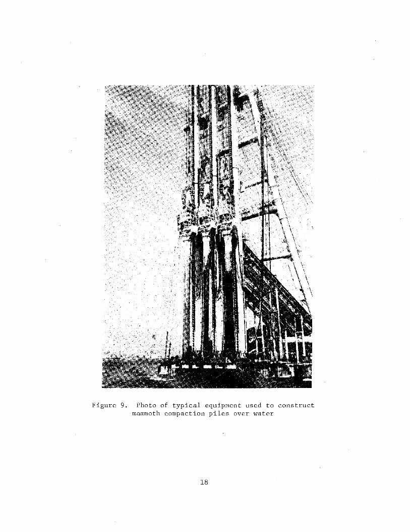
Figure 9. Photo of typical equipment used to construct mammoth compaction piles over water
18
Sand pile diameters of 32 to 79 in. are constructed using 24- to 47-in.
casing and 160- to 400-hp vertical vibrators. A 10- to 40-hp horizontal
vibrator is sometimes used at the bottom of the casing. Table 2 gives
specification~ of horizontal vibrators (Vilots) used to construct strong
sand piles. At t~t present time, however, the strong sand pile method is
not nearly as popular in Japan as sand compaction piles.
20. The diameter and density of both sand compaction piles and strong
sand piles can be varied by changing the (a) casing diameter, (b)
extraction rate, (c) compressed air pressure, (d) time of vibration and, (e)
size of vibrator. Further, a pile diameter varying with depth can be
obtained by changing (b) through (d) during casing extraction. During
construction the diameter of the sand pile, volume of sand supplied and
discharged, casing tip elevation, and the power (amps) used by the vibrator
are frequently all automatically recorded.
19
PART III: DESIGN THEORY FOR SAND COMPACTION PILES
Introduction
21. In thlH section the theory for designing sand compaction piles
and mammoth compaction piles is presented as presently followed in Japan.
Sites underlain by both ~and and cohesive soils are considered. The
methods presented can also generally be used for strong sand piles which
are constructed as previously described using both a vertical and
horizontal vibrator.
Area-Replacement Ratio
22. The volume of soft clay or loose sand replaced by sand is one of
the most important factors in improving weak ground using sand compaction
piles, strong sand piles, or mammoth compaction piles (and also stone
columns). To quantify the amount of soil replacement, define the area
replacement ratio a s
as the fraction of soil tributary to the pile re-
placed by the sand compaction pile:
a s
A /A s
(1)
where A is. the cross-sectional area of the completed sand compaction s
pile and A is the total area tributary to the sand compaction pile, as
illustrated in Figure 10. The area replacement ratio can be expressed in
terms of the diameter and spacing of the sand compaction pile as follows:
where
a = C (Q)2
s 1 s (2)
s = center-to-center spacing (pitch) of the sand compaction piles
D
a constant dependent upon the sand pile pattern used; for a square pattern C1 = n/4 and for an equilateral triangular pattern cl = n/(2/3)
diameter of the completed sand compaction pile (not the diameter of the ca.:cing)
20
23. For an equilateral triangular pattern of sand compaction piles,
which are more frequently used in the United States for stone columns, the
area-replacement ratio is then
( 3)
In working ,,ith ground improvement using sand compaction piles (or stone
columns), it is important to think and work in terms of the area
replacement ratio. Area-replacement ratios for sand compaction piles
constructed on land are typically 0.4 to 0.5 (refer to paragraph 55).
Sites Underlain by Sand
24. For sites underlain by sands the required sand compaction pile
spacing (pitch) and diameter can be estimated using the theoretical
approach described by Aboshi et al. (1979; Tanimoto (1973); Ichimoto
(1980); and others.* This approach is based on the fact that the
strength and settlement properties of a cohesionless soil are primarily
determined by relative density. The importance of stress history, grain
size, gradation, angularity, and other characteristics should, of course, not
be forgotten. For each cohesionless soil a single void ratio is associated
with each value of relative density. If the required increase in relative
density of a loose sand can be determined from stability, settlement, or
liquefaction considerations, the required reduction in void ratio can be
readily estimated using basic relationships described in this section.
25. Assume that sand compaction pile construction causes, during
installation, only lateral displacement of the loose sand. After making
this assumption, the size of the sand pile required to cause the decrease
in void ratio by displacement of the loose sand to the desired value can
then be calculated.
26. In Japan, as elsewhere, many practicing engineers use standard
penetration test results as the basis for making stability and settlement
* SVS Method Technical Information, "Kensetsu Kikai Chosa Co., Ltd., anonymous (undated), Osaka, Japan; "Sand Pile Construction Using Vibrating PileDriving Equipm2nt, "Kensetsu Kikai Cosa Co., anonymous (undated), Osaka, Japan.
21
estimates. Sand compaction pile design can be based on either standard
penetration resistance or relative density since the two quantities can be
related to each other. The design procedure requires the standard pene
tration resistance value N to be corrected for the effect of overburden
pressure using for e~~~ple the results of Holtz and Gibbs (1957) or Ogawa
and Ishida (1965).
Dei?ign approach
27. To develop a practical design method, assume the total volume
tributary to a sand compaction pile remains constant during the site
improvement work. Also, neglect any increase in relative density caused by
vibration as the casing is driven, and assume the loose sand is only
displaced laterally away from the sand pile during construction. The
relationship between the required volume of the sand compaction pile and
the change in void ratio or tl'w in situ sand can be derived using the
notation and relationships shown in Figures 10 and 11. Referring to Figure
11, let the change in volume of the in situ sand equal the volume of the
sand compaction pile S giving
which simplifies by cancellation to
-s V(e -e1
) s 0
( 4)
(5)
The volume of solids equals the volume of voids divided by the initial void
ratio
v V /e (6) s v 0
Then substituting equation ( 6) into (5) gives
v - v s (e - e ) e 0 1
(7) 0
28. Now, consider a thin, horizontal slice of sand compaction pile and
tributary soil having a unit thickness ! = 1, as illustrated in Figure 10.
Referring to Figure 11a, the total volume of material originally present is
22
v v
s
j~
I I I I
0s 1--
s
I I
a =A /A I s s _ A • R. = S
I t 5
= unit length
Tributary Area A = A + A s c
G,--~,M~v~=-~~~~~~~~~~~~~
I I
Figure 10. Geometry and stress state associated with a soil reinforced by sand compaction piles
,~ A ., I . A
I Sand Pile'
Voids Voids
e • V /V V ~ V (l+e ) v s 0 s 0
(a) Initial (b) After Densification
Figure 11. Volume block diagram of in situ sand before and after sand pile construction
23
A X Q, v + v v + v
(8) v s
Solving Equation (8) for the original volume of voids V and letting £=1 v
gives
v v
( 9)
Now divide each side of Equation (7) by the total area A, and replace Vv by
Equation (9). This gives upon simplification the ratio of volume of sand
compaction pile to the total volume for a unit increment of length
-s A
( 1 0)
where
S volume of sand compaction pile per unit length, t
A total tributary area to one sand compaction pile
e0 initial void ratio of the loose sand
e1 void ratio of the loose sand after sand compaction pile
construction
Since the volume of sand compaction pile S is defined for a unit length ~ l
of construction, the area-replacement ratio, which is defined by Equation
(1), equals S/A giving
where
a s
e0 initial void ratio of loose sand before improvement
e1 final void ratio of loose sand after improvement
( 11 )
29. The above expression can be changed to a more useful form for
design by considering a unit length of sand pile construction. For a
square sand compaction pile grid having a spacing s, the total volume
(Figure ll(a)) is equal to V = s x s x £. For a unit length £ = l, solving - 0
for sand compaction pile spacing s gives for a square pattern
24
1 + e 0
e - e 0 1
~ 1 + e - 0 . s = e - e
0 1
and similarly for an equilateral triangular pattern
s = 2~~,~ - v cc
3 0
wher'e
s spacing (pitch) of the sand compaction piles
V0
total volume of soil (in situ sand plus sand compaction
pile) tributary to the sand compaction pile per unit
length of depth
s D
volume of sand compaction pile per unit length of depth
p.i. diameter
( 12a)
( 1 2b)
Due to waste and densification of the aodcd sand during construction, the
volume of loose sand brought to the site for sand pile construction must be
greater than the volume of compacted sand pile. The ratio of volume of
loose sand brought to the site to densified sand within the sand compaction
pile has been found in Japan from experience to typically be between 1.2
and 1.4. In practice a ratio between 1.2 and 1.3 is frequently used.
30. The following trial and error design procedure can be used to
determine the required sand compaction pile spacing (pitch) and sand
volume:
1. Make a preliminary estimate of the required relative density after improvement of the in situ sand.
2. Select, based on the soil and loading conditions, a trial spacing (pitch). Typically this spacing is between 5.5 and 8 ft.
3. Estimate the initial and final void ratio of the in situ sand. Tl1e best approach vo,;lcj tJe to determine in the laboratory the actual relationship between void ratio and relative density for the sand encountered at the site. As an expedient alternate the lower portion of Figure 12 can be used as a guide in estimating the void ratio-relative density relationship. Three "typical" void ratio-r'elative density curves are given for varying uniformity coefficients Cu and effective grain sizes D6o· In Japan curves similar to FigurE. ·? apparently are frequently used for design.
4. Using the change iG vzlld ratio of the in situ sand obtained from Step 3, calculate the required volume of densified sand per unit
25
so (a)
40
'lit;-._"t;
c: "' 0 ;;' .... 30 cS'll .., '" .... _,_'II .., QJ:Z ...,,.., r.: QJ . 'II" "" QJ 20 «.«; u "0 c 4,> ... "' '" .., ., "' C:..-1
'" "' .., QJ 10 UlC<:
0 (b)
0.2
0.4 QJ
0 0.6 .,... w "' 0.8 <=G
"0 .... 1.0 0 ::>
1.2
1.4 0 0.2 0.4 0.6 0.8 1.0
Relative Density
Figure 13. Effect of sand compaction pile construction on SPT value at center of sand pile ("Sand Pile Construction Using Vibrating PileDriving Equipment," Kensetsu Kikai Chosa Co., Ltd., anonymous (un-
dated), Osaka, Japan)
Figure 12. Relationship between relative density and penetration resistance or void ratio (after Tanimoto,
26
-;:: 0 ..... w u ::l ... w
"' c: 0 u ... QJ w .... ~
1973)
0.025-0.075
0. 075-0.125
0.125-0.175
• 0.175-0.225
0~--~----~--~----~--~--~~ 0 10 20 30
SPT Value, N0
(Before Construction)
length of depth using either Equation (12a) or (12b) depending on the sand compaction pile pattern. Then calculate the required sand compaction pile diameter from the known sand volume s or using Equation (2). The required replacement ratio can be determined from Equation (11). The sand compaction pile diameter used in practice ~s usually between 24 and 32 in.
5. Estimate the required inside diameter of the casing to be used in constructing the sand compaction pile considering the initial relative density and characteristics of the soil and vibratory hammer-pile system. The constructed sand compaction pile diameter is usually taken as 1.5 to 1.6 times the inside diameter of the pipe.
6. If the required sand compaction pile and/or pipe diameter is not practical, select a new spacing (pitch). Refer to paragraph 55 for typical sand compaction pile and pipe diameters used in Japan. Then repeat Steps 1 through 6, considering the new area replacement ratio as and available equipment.
31. The above steps give a diameter of the sand compaction pile that
is compatible with the final relative density of the in situ sand assumed
in Step 1. Following Steps 1-6 does not, however, ensure an overall safe
design. Therefore, the preliminary design must be checked and revised as
necessary for safety with respect to stability, settlement, and liquefaction
using appropriate engineering analyses.
Design based on SPT
32. An alternative approach used in Japan for designing sand
compaction piles is based on previously observed increases in standard
penetration resistance of sand compaction piles during construction. Field
measurements made before-and-after sand pile construction show that the
standard penetration resistance after construction significantly increases
as the area replacement ratio as becomes greater (Figures 13 and 14).
Figures 13 and 14 can therefore be used to estimate the required area
replacement ratio after selecting a final field value of standard
penetration resistance. This empirical approach can be easily used to
verify the results obtained from the theoretical method given previously.
Casing extraction
33. Sand compaction piles are densified as previously discussed using
a stroking motion as the casing is extracted from the ground. The required
27
_..... 1:: 0
.,.; .... u ::l ).< .... r.JJ 1:: 0 u
'"' <lJ .... ..... ...: '--"
,....; z
<lJ ::l
,....; ~ :> E-< il< <J)
40
30
20
10
0 0
LEGEND
Symbol as
0 0.025-0.075
• 0.075-0.125
0 0.125-0.175
• 0.175-0.225
10 20
SPT Value, N0
(Before Construction)
30
Figure 14. Effect of pile construction on SPT value one-half way between sand piles ("Sand Pile Construction
Using Vibrating Pile-Driving Equipment," Kensetsu Kikai Chosa Co., Ltd., anony-
0
mous (undated), Osaka, Japan
Figure 15. Notation used in stability analysis (after
Aboshi, et al., 1979)
28
0 s
z
distance to redrive the pipe can as a rough approximation be estimated
using the following empirical expression*
where:
H D
A H ( 1-n' _E.)
E A s
Ho distance casing must be redriven downward
HE distance casing is extracted before redriving
n' empirical factor that can be taken as about 0.8
Ap inside area of the casing
As area of the completed sand compaction pile
( 1 3)
More rational methods for estimating the distance to redrive the casing are
apparently not presently used in Japan.
34. During the extraction-redriving cycle the quantity of sand
discharged is apparently not exactly proportional to the extraction height
H >~ E. Because of its approximate nature, the above expression should be
used together with standard construction practice for specifying values of
HE and Ho. Usually in practice the casing is extracted 6.5 to 10 ft and
redriven about one-half that height. Fudo Construction Company typically
extracts the casing 6.5 ft.
Average standard penetration resistance
35. The average weighted penetration resistance, N of the improved
ground including the installed sand compaction pile can be estimated using
the following expression*
where
-N aN + (1 - a ) N'
s p s s
N average weighted standard penetration resistance of the
improved soil including the sand compaction pile
as area-replacement ratio
Np standard penetration resistance of the sand compaction pile
N' standard penetration resistance of the improved soil usually s
taken one-half the way between the sand compaction piles
( 1 4)
* "Sand Pile Construction Using Vibration Pile-Driving Equipment," Kensetsu Kikai Chosa Co., Ltd., anonymous (undated), Osaka, Japan.
29
At sites underlain by sand, the average weighted standard penetration
resistance is frequently used for design and given in specifications as the
end product of sand compaction pile construction.
Sites Underlain bl'_ Cohesive Soils
Stress concentration
36. Sand compaction piles are frequently used in very soft cohesive
soils to provide stability, accelerate consolidation, and reduce settlement.
Both field and laboratory studies show that, upon loading, an important
concentration of stress as shown in Figure 10 occurs in the relatively
stiff sand compaction pile. The stress concentration occurs since the
total settlement in the sand and clay is approximately the same (Aboshi, et
al., 1979). This concentration of stress forms the basis of design for
both stability and settlement of a sand compaction pile reinforced cohesive
soil. The concentration of stress is expressed by a stress concentration
factor n defined as
n
where:
a I a s c
o8 vertical stress in the sand compaction pile
oc vertical stress in the clay
(15)
37. The value of the stress concentration factor used in design has
an important effect on both calculated settlement and stability. Typically,
a stress concentration factor of about 3 to 5 is used in Japan based on
past experience and field measurements (refer to paragraphs 64 and 65).
38. Consider the case of a very wide, relatively uniform loading a
applied to a large group of sand compaction piles having a square or
equilateral triangular pattern. The average stress a (or stress increase
~o) which must exist at a given depth over the total tributary area for
equilibrium of forces must equal
o=a •a +a (1-a) s s c s ( 1 6)
where all the terms have been previously defined. Solving Equation (16)
for the stress in the clay and sand using the stress concentration fa~tor n
gives
30
0 c
o/[ 1 + (n - 1) a ] s l.l 0 c
( 17a)
( 1 7b)
where l.lc and lls are the ratio of stress in the clay and sand, respectively,
to the average stress over the tributary area. For a given set of field
conditions, the stress in the sand and clay can be readily determined using
Equations (17) upon assuming a value of the stress concentration factor.
Stability
39. In Japan one of the most important uses of sand compaction piles
for site improvement is to prevent a stability type failure of wide fills,
tanks, dikes, embankments, and heavily loaded storage yards constructed over
very soft sediments. The stability failure might be either within recently
placed hydraulic fill or the underlying soft native foundation soil.
Frequently moderate to large preloads are used to limit settlements beneath
tanks and heavy storage yards. The stability of an improved site
reinforced with compaction piles is usually analyzed in Japan using a
conventional circular arc stability analysis and the average weighted shear
strength of the material within the tributary area of each pile.
40. Consider the stress state within a selected sand compaction pile
at the depth where the circular arc intersects the centerline of the pile
using the notation shown in Figure 15. The effective stress in the sand
compaction pile due to its weight and any externally applied loading can be
expressed as
where
0 z Y'z + f..o l.l s s
az vertical effective stress acting on the sliding surface
of a sand column
( 1 8)
Ys unit weight of sand (buoyant if below the ground water table)
z depth below the ground surface
t-.o stress increase at depth under consideration due to the
embankment loading
lls stress concentration factor for the sand column, Equation (17b)
31
41. Referring to Figure 15, the shear strength of the sand column can
then following common United States practice* be expressed as
where
T s
Ts shear strength in the sand column
a inclination of the shear surface with respect to the
horizontal
$s = angle of internal friction of the sand column
( 19)
The average weighted shear strength within the area tributary to the sand
pile then becomes
where:
1 average weighted shear strength
Tc undrained shear strength of the cohesive soil
and the other terms have been previously defined.
(20)
42. The weighted average unit weight within the reinforced ground is
used in calculating the driving moment
Y = Y • a + Y • (1 -a ) avg s s c s ( 21 )
where Ys and Yc are the saturated (or wet) unit weight of the sand and
cohesive soils, respectively. In this approach the weighted shear strength
and unit weight are calculated for each row of sand columns and then used
in a conventional hand stability analysis. A more detailed consideration
of methods for performing stability analyses of soils improved with
granular columns is given elsewhere (Barksdale and Bachus, 1983a).
* In Japan apparently, cosa rather than 2 cos a is at least sometimes used.
32
Increase in Shear Strength Due to Consolidation
113. The shear streq)th of a soft cohesive soil reinforced with sand
compaction piles rapidly increases during and following construction of an
embankment, tank, or foundation. The additional stress due to construction
results in an increase in pore pressure causing consolidation of the soil
accompanied by an increase in shear strength. The rate of embankment
construction is frequently controlled to allow the shear strength to
increase so that the required minimum safety factor with respect to a
stability failure is maintained.
44. The undrained shear strength of a normally consolidated clay has
been found to increase linearly with effective overburden pressure
(Leonards, 1962). For this type cohesive soil the undrained shear strength
can be expressed as
c
where:
c undrained shear strength
K • a 1
K1 the constant of proportionality defining the linear increase
in shear strength with a, i.e., K1 =c/o
a effective overburden pressure
(22)
45. For a cohesive soil having a linear increase in shear strength
with o, the increase in undrained shear strength ~ct with time due to
consolidation can be expressed for sand compaction pile improved ground as
where:
~ct increase in shear strength at time t of the clay due to
consolidation
~a average increase in vertical stress in the unit cell on the
shear surface due to the applied loading
~c stress concentration factor in the clay, Equation (17a)
Ut degree of consolidation of the clay at time t
33
(23)
46. The applied stress ~a includes the embankment loading and can be
reduced, if required, to consider the spreading of stress in the sand
compaction pile improved ground. A discussion of spreading of stresses in
sand compaction pile improved ground (which is similar to stone column
improved ~ound) is briefly discussed in the next section and in more
detail byBarksdale and Bachus (1983a). Equation (23) gives a convenient
method for estimating the increase in shear strength in normally
consolidated cohesive layers at any time provided K1 has been evaluated
from field testing or estimated (Leonards, 1962). More sophisticated
methods are available for considering increase in shear strength (Ladd and
Foott, 1977).
47. If a soft cohesive soil is reinforced with sand compaction piles
a reduction in settlement occurs (Ichimoto, 1980; Aboshi et al., 1979) with
the magnitude depending upon the amount of stress concentration. To
estimate the settlement reduction, assume that the vertical stress carried
by the sand compaction pile and cohesive spil does not change with depth.
This assumption is discussed in paragraphs 48 and 49. From conventional
one-dimensional consolidation theory the settlement of the cohesive layer
can be expressed as
~H
where:
m (llo ) H v c
~H settlement of the compressible cohesive layer
(24)
my modulus of volume compressibility determined from laboratory
consolidation tests
~ac average stress change in the cohesive soil due to construction,
i.e., llac = lJcllo
H thickness of the compressible layer
48. Calculation of settlement using Equation (24) or alternate
expressions for settlement is straightforward for a site reinforced with
sand compaction piles and subjected to a uniform loading over a very large
area. Due to symmetry of loading and geometry due to the large extent of
the area, the external load lla applied over the area tributary to a given
sand compaction pile remains for practical purposes in that tributary area
34
all the way down to the supporting strata. For this condition the average
increase in stress in the cohesive soil ~ac remains approximately constant
with depth, and can be calculated using Equation (17a). An estimated value
of the stress concentration factor based on past experiPnce and field
measurements is used in Equation ( 17a). The calculated incrPa5( jn stress
in ~.lJe cohesive soil ~oc is then used in Equali on ( 24) to estimate the
settlement or the cohesive layer.
49. For sand compaction piles covering an area of limited extent, a
concentration of vertical stress still occurs in the compaction pile. With
depth, however, the stress is gradually distributed outward to the
unreinforced soft cohesive soil. The stress can be approximated using
a Boussinesq stress distribution for a homogeneous soil (Aboshi et al.,
1979). For small groups of sand compaction piles use of a constant
verLical stress with depth would be overly conservative while use of
Boussinesq theory would tend to somewhat underpredict the settlement. For
stress distributions that vary with depth, settlement in a cohesive soil
can still be calculated by dividing it into sublayers and using Equation
(24) together with a suitable distribution of stress. Stress concentration
effects are considered using Equation (17).
50. In calculating settlement the modulus of volume compressibility
is usually taken as that of the cohesive soil before construction of the
sand compaction piles.* Aboshi et al. (1979) report good settlement
predictions using Equation (24). In Japan settlement estimates are
routinely made using the above method in the soft clays. Settlements of 7
to 10 ft frequently are calculated vhen land is reclaimed from the sea.
Aboshi et al. have found from field measurements that the settlement of
sand compaction piles and the surrounding soft clay is approximately equal.
Conclusions
51. A considerable number of sand compaction piles, designed using
the theory presented in this section, have been constructed and have
performed satisfactorily. This theory is felt to be generally
representative of the practice presently followed in Japan. As is common
* "Sand Pile Construction Using Vibrating Pile-Driving Equipment, "Kensetsu Kikai Chosa Co., Ltd., anonymous (undated), Osaka, Japan.
35
elsewhere, some Japanese engineers apparently rely heavily on past
experience and rules-of-thumb for the design of sand compaction piles.
Specific site and loading conditions, past experience and usual design
practices should of course always be carefully considered in selecting a
final design.
36
PART IV: GENERAL DESIGN CONSIDERATIONS
Applications
52. The Japanese use extensively sand piles \J..c,, sand compactioiJ
piles, mammoth compaction piles, and sand drains) for many chfferent
applications usually involving land that has been reclaimed fr·om the sea.
A summary of the detailed usage of sand compaction piles in Japan is given in Table 3. Fills, embankments, and tanks are routinely placed on very soft cohesive soils having shear strengths as low as 100 psf; construction
is common on soils with shear strengths from 200 to 300 psf.
53. In reclaiming large areas of land from the sea, usually a dike is first constructed around the area to be reclaimed. To prevent a stability
failure, the soft sediment is either dredged out and replaced with
hydraulic fill, or else the dike is placed directly on the soft sediment
after reinforcing it with closely spaced, mammoth compaction piles as shown in Figure 16. Mammoth compaction piles have the following advantages
over conventional dredging and hydraulic replacement:
1 . Since the sediments are not actually removed using the mammoth compaction piles method, disposal of waste sediment is not necessary. Elimination of waste disposal is highly desirable in Japan from the environmental viewpoint because of the high population density.
2. A denser sand can be obtained ~sing the mammoth compaction piles method than for dumped hydraulic fill.
3. The vertical sand piles constructed by the mammoth compaction piles method require a minimum amount of clearance outside the proposed construction. In contrast, dredging necessitates the use of very flat side slopes in the soft ocean sediments requiring additi~nal space outside the construction area.
4. The mammoth compaction piles method can be used adjacent to existing structures.
54. Mammoth compaction piles are frequently used in reclaiming land
from the sea in Japan. Conventional dredging and replacement techniques,
however, are still employed where environmental or other restrictions do
not prevent their use. Other applications of this method include embankments, quay wells, piers, and breakwaters (Figure 17).
37
w (X)
~-Clients
Table 3
Detailed Usage of Sand Compaction Piles in Japan
(Composer System, Fudo Construction Co., Ltd.,
Anonymous (undated), Tokyo, Japan)
en <-1:1 » 0.. Types ~ (1J ... en
0 ClJ ;J: 0 ClJ of ·.-i ... rl u ·.-i +J ;:l ·.-i ~ Soils <J +J "' <J en (1J ;J rl ~ ·.-i ;:l en ~ ... ;:l .-I 0.. m ClJ +J <J rl ..0 ... cn ·.-i 0 cn cn .,.(
"' ;:l 0 ... .., ~ u en rl ~ ... ~ p.. u ;:l ~ "' rl ·.-i
ClJ +J (1J ~ ... ClJ +J rl a ~ ;:l ..,
en "' rl » ... •.-i ClJ +J 0 00 0 I'Q QJ
a ~ ... •.-i 0 0 » Ul u ~ ·.-i » 00 QJ en 0 Ul Ul "' en +J "' Q <J s en 0 ;J: en ;:> Ul rl 00 rl ..... ..... "' ;J: •.-i ·.-i ... u 0 k 0 » » u ~ ·.-i 0 0 ~ z .c en rl QJ ClJ p.. ClJ ClJ .., ClJ "<:! ·.-i 0 Applications 00 ;:l ..0 > .!G a "<:! ~ ..... » g "<:! k Ul » >,+J ClJ ·.-i 0 ;:l 0 "' ;:l <J rl C'j 0 "' Q (1J k ~-< cn en :r: :r: p.. (.!) "' ;:;:: ClJ ·.-i ·.-i ,..., Ul rl Ul "' ClJ rl +J .., ClJ ClJ » rl k ;:l ri u <=Q "' en en 1-< ~ ~ a k . "' rl 0 .., ..0 Q) "' ClJ » ·.-i .,.( ·.-i 0 "' "' "' QJ ..... ;J: QJ k <J 0.. u k .., en "<:! p.. <J a a!'<. p.. 0.. p.. .c ClJ ..0 ClJ +J QJ •.-i UJ .., ..... 0 ~ Q) ClJ ·.-i .,.( "' "' "'
.., k ;:l .., ClJ rl .r:: .,., rl 0 0 (\j ClJ 0.. ;:;:: ;:;:: ..., ..., ..., 0 p.. U) Ul p.. ~ U) ;:;:: ::::> Ul o-1 Ul 0 Ul
Prevention of Sliding Failure e 0 oe 000 0 eo D Approach of Embankment 0 oe 0 00 0 Vibration Resistance 0 eo 0 Extra Heavy Rail Load 0 000 Sliding Resistance for Heavy Yards 0 •e 0 Foundation of Tank •• 0 ••• 0 Foundation of Structure D 0 00 000 00000 Compaction of Cellular-fill DO 0 0 00 Sliding Resistance for Quay Wall 00 0 Horizontal Resistance of Ground
Prevention of Settlement 0 0 00 Promotion of Settlement 0 0 00 Improvement of Road Base D D 0 Foundation of Building 0 0 0 0 00 Excavation, Prevention of Heaving 0 D 0
--
I
~ ClJ "<:! a 0 ;:l 0 rl rl 00 "' 0 ·.-i :> » v <J
k 0 ClJ +J ClJ 0 0.. QJ > co en
.!G ... .. .. . . "' 00 ;:;::
~-
• : ·) g
0 0
• • 0 0 0 D
!O D 0 0
' ' ......
HCP Piles
Reclaimed Land
I I
1 I
Sand Drains
I I I I I 1
MCP Piles
Figure 16. Land reclamation using mammoth compaction piles (MCP)
(a) Bridge Pier
(c) Impoundment
Original Surface -· ---·
(b) Waterfront
(d) Impoundment
Figure 17. ("Mammoth
Typical application of the mammoth pile method Compozer System," Fudo Construction Co., anony
mous (undated), Tokyo, Japan)
39
General Criteria and Practices
55. Japanese design practices and design criteria for sand compaction
piles for selected organizations are summarized in Table 4. Both square
and triangular grid J~tterns a~e commonly used in Japan for all types of
site improvement work. Sand compaction piles constructed on land have area
replacement ratios varying r~om 40 to 50 percent while sand piles
constructed in the sea have area-replacements ratios varying from 20 to 90
percent depending on the application and soil strength. A higher
replacement is usually employed for reclamation of land from the sea using
the mairumoth compaction piles method than for projects on land; for this type
reclamation the piles often touch each other with typical area-replacement
ratios of 70 to 80 percent. Finished sand compaction pile diameters generally
vary between 24 and 32 in., and mammoth compaction pile diameters between
32 and 70 in. A pile spacing (pitch) is used between 4 and 10 ft. Typically,
however, the spacing is between 5 and 7 ft. If a small sand compaction pile
spacing is used, problems may be encountered in previously constructed
adjacent piles, and special precautions must be taken.
56. Sand compaction piles become hard to install in soils having
standard penetration resistances greater than about 15 to 20. To penetrate
very dense sand layers and hard clay seams water jets having pressures from
70 to 1,200 psi are sometimes placed on the sides of the casing (Hayashi,
1981). Japanese engineers apparently prefer to carry sand compaction piles
down to a bearing strata. This practice is in agreement with stone column
design practice in the United States and Europe. However, when the bearing
stratum is quite deep, a floating sand pile design is apparently used in
Japan in some instances for stability applications (Mizutani, 1981 ).
Stability Considerations
Stability performance
57. The fact is well established in Japan that sand compaction piles,
mammoth compaction piles, and strong sand piles have a record of good per
formance with respect to stability. All of the Japanese engineers inter
viewed pointed out that only one to two stability failures of these type
piles have been reported in Japan. TI1e absence of stability failures is
40
Table 4
Summary of Sand Compaction Pile Design and Construction Practices in Japan
ta t .. n onstruct on Or~anir.ation Type Las ng Pile .,,
o• Organization/ • a Diam. Diam. Spacing Length Soil Press. Sand Production Cost Connents Project Project (o) n . SF <=> (mm) (m) (m) Conditions (kg/crn2 ) Rate ·-Kensetsu Manufacturer of 20-45 4-S 1.3 1. 7-2.0 3-S Consolidation; 80% during < nnntruc-K.ik.ai Vibratory Pile 450 tion (folloving Civil Engr & Choaa Co. Driving Equip, for Geot. As&oc. guidelines); Ltd. coarae
End support duirable- f•Y stability clean not necessary; sand pfl.-. ··lS:t silt sand
Fudo Lorge I 30 3 1.2-1.3 500 800 1.2-J.O 3-5 Always end support Con st. Construction (it Typical: Co •• Company !lilly 2 Sand for Piles: <IO:t silt; 0.01 to Ltd. be Sea-may 1 11111. sand
35°) touch, 1.6-J.O LIIC Tanks
Nippon Large I 30° J(4) - 1.25 400 700 2-2.5 Consolidation: 80% over 8 months to Kokan Steel clumped
10(4 ) 1 yr. (for 2-3m settlement) Co., Company 40° Pressure: Iron Ore Yard: 4000-6.'1 10 psf Ltd. vib.
(N•20-- with 2 to 2.5m pitch 25)
May be Go if posdble to end support
45°
Waste Contractor o. 79 800 1200 1.20 0 24 24•-v.soft 7(1) Clf'nn. 21 piles Vertical Vibrator: 120 kw (KMZ -Disposal Nippon to firm. silt fin~~ day f0r 3 24,000A) .j::-- I Station- Kaikou (N<5); lOa to !!lied. vibrators 450 J..VA Generator f-' Toyoko (Soil fira silt sand (13 hr. Bay - Improve- (N•5); 16m shift) !eering top of firlll eil t 6000 MCP ment Co.) water Piles
Apart- Contractor 0.27- 800 Variable 1. 70 [] 28- 5-6m - v .loose 3-4 Clean 45 piles/ $770/ Vibrator: 300 kw (KM4- 48,000A) ment Nippon 0.49 1350(bot) 32 ~~and; 23-26 m coarse day for pile 450 kVA Generator Bldgs. Kaikou lOOO(top) v.soft clay sand 3 vibra- Horir.. Vib.: SSP 7.5 kw Osaka Bay N:o; Gnvel with tor a 1584 SSP supporting shells Casing pulled down uBing cable and Piles layer; 2-3m winch; water added to sand
water
LNG KAJIMA. Corp. ' - 0.11 400 600 1.706 6 3m sand 7(1) Clean 60 piles/ Vibrator: KHZ - 12,000A (90 kv) Storage General
I (N•4-9) fine- day avg. 3840 psf uea loading; 3 t11 pr!!lo•· ,: Tank Contractor la.tlt med. for 3 !IIOnths Toyoko (N•4); 2. 5m sand
Bay sand (N•ll-"58.2 34) dia. 1069 sc Piles
LNG Shimizu Co. 0.11 400 650 1. 70 [J 15 40 m fine 7 Hed. 20 piles/ 1511- Vibrator: m2 - 12.000A (90 kw) Storage General sand with
~·· day avg. $196(2) Lift casing 3ao repenetrate 1.5m Tank Contractor silt <5% 4Qt crane; 194HP Compressor
silt
Oil Tank Chou San
1-0.08 400 600 2.0 /),. 8-12 8-10• well- Yes Well- 20-40 4 Rigs: 1 -120 kw. 3-90 kw-
Factory Development graded gravel graded piles Pile Installation: 6-7 lllin./pile Kaoshung Enterprise with sand sandy day/ Compaction: Extraction- 3. 7 m, City Co •• Ltd. (H•S-10) w. gravel uchine Repenetration 2. 7 m Taiwan 3 clay layers; (25 avg.) Sand Piles: For liquefaction -sand 6:00 a.m.
concrete piles installed to 10:00 p.m. (2 shifts)
Notes: 1. Air pressure vas apparently given at compressor and not top of sand pile.
2. Cost of just the sand; coat of sand compaction piles is one-half the cost of a precast concrete pile; driving costs are about the same.
3. Includes $7.35/m for cost of sand.
rather remarkable considering the widespread use in Japan of sand compaction
piles for this purpose.
58. Aboshi et al. (1979) have described a well-known tri~l embankment
constructed on 36 ft of organic silt havine; a shear strength of 200 to 300
psf. The organic silt was underlain by 95 ft of peat with a shear
strength varying from 150 psf to ~~0 psf. A test seution without sand
compaction piles failed at an embankment height of 21 ft. Another section
of the embankment was constructed using a square grid of sand compaction
piles at a 6.6-ft spacing resulting in an area-replacement ratio of only
0.1. Nevertheless, failure did not occur under an embankment height of
48 ft. The exceptional performance of this embankment suggests why the
primary use of all types of sand compaction piles in Japan is to prevent
stability failures.
59. The method of stability analysis previously presented has been
found in Japan to give conservative results for embankments constructed on
sites stabilized with sand compaction piles (Aboshi et al., 1979). In 15
test embankments, embankment loads between 1,600 and 7,100 psf were
supported by sand compaction piles having area-replacement ratios between
0.16 and 0.20. Calculated safety factors of these embankments with respect
to a stability failure varied from 0.99 to 1.59 with seven of the
embankments having safety factors less than 1.10.* Nevertheless, none
of the embankments failed even though over one-half of them were
constructed over soils having shear strengths between 120 and 300 psf.
Angle of internal friction
60. The angle of internal friction ~s of sand compaction piles used
for stability analyses in Japan appears to vary from 30 to 40° depending
upon the organization (Table 4). Fudo Construction Company, Ltd. routinely
use ~s = 30° for design although it is admitted that ~ could be as great as
35°. Nippon Kokon Co., Ltd., a very large steel company, uses 30° for
dumped sand and 40° for vibrated sand having an N value of 20 to 25; for
this condition they feel the angle of internal friction may be as large as
45°. Kensetsu Kikai Chosa, a well-known Japanese manufacturer of vibratory
hammers, recommends angles of internal friction between 20° and 45°
*It is not clear if consolidation of the foundation soils during construction was considered in the stability analyses. Undoubtedly long-term consolidation helps to explain the success of these embankments.
42
depending upon the material; for a coarse clean sand a value of 45° is
recommended. The validity of using angles of internal friction of 40° or
more for design is not recommended by the writer. Such high friction angles
would require a very small void ratio and coarse, angular particles.
61. For 8ArJd compaction pile dc~ign in the United States, a
rsasonably conservative value of the anglP of internal friction should be
emp~ .yed in stability calculations at least until sufficient experience has
been gained using this technique. For sand compaction piles constructed
using sands with less than 8 percent silt content, the recommendation is
made that an angle of internal friction ¢s between 30° and 38° be used
depending upon the effective grain size, gradation, and densification
attained. The angle of internal friction used in design should of course
be no greater than the value of ¢s estimated from the design relative
density and/or standard penetration resistance obtained from field
measurements and corrected for overburden pressure.
62. The writer recommends a safety factor with respect to a stability
failure of at least 1.3 and preferably 1.5. It is recognized that the
sponsor (CE) has its own criteria on safety factors for slope stability
analyses defined in EM 1110-2-1902 US Corps of Engineers, 1970. The actual
safety factor selected should depend upon a number of factors including
(a) the specific problem including site conditions and type construction,
(b) whether an increase in shear strength due to consolidation has been
considered, and (c) existing criteria of the design agency. In Japan a
safety factor of 1.2 to 1.3 is commonly used for stability applications.
Local bearing failure
63. Sand compaction piles, when used for stability applications,
carry reasonably large shear forces (but not as large as stone columns).
These shear forces could conceivably result in the sand compaction pile
punching into the surrounding very soft soil although this type failure has
not been reported in Japan. A local bearing (punching) type failure was
observed in the US at Jourdan Road Terminal during a direct shear test on
a stone column (Barksdale and Bachus, 1983a). Stone columns in general
would be more susceptible to a local bearing type failure than sand
compaction piles since they are usually designed to carry higher axial and
hence shear loads (i.e., stone columns are usually designed using a greater
angle of internal friction). Nevertheless, the possibility of a local
43
bearing failure does exist for sand compaction piles constructed in
extremely soft sediments having undrained shear strength less than about
250 psf. A discussion of local bearing failure, together with a
presentation of design theory and design charts has been given elsewhere
(Barksdale and Bachus, 1983b).
Stress Concentration
64. The value of the stress concentration factor n used has an
important effect on both stability and settlement calculations. For a test
embankment at Fukuyama the measured stress concentration factor, which was
almost constant with depth, increased from to about 4 as the 13-ft-high
embankment was placed (Aboshi et al., 1979). After the embankment was
completed the stress concentration factor continued to increase up to about
5 as consolidation occurred. Further, the average stress concentration
factor n measured at twenty sand compaction pile sites in Japan underlain
by soft clay is 4.9, with observed values for the twenty sites varying from
2.5 to 8.5.* An n value of 4 was found to give the best agreement with
the measured time rate of settlement curve for one test embankment.
65. In estimating the magnitude of stress concentration the reader
should remember that theory shows n to increase for (a) increasing values
of the modulus ratio of the sand column to the in situ soil and (b) for
decreasing area replacement ratios (Ogawa and Ishido, 1965). For design
Fudo Construction Co., Ltd. uses a stress concentration factor n of 3.0.
Nippon Kokan Co., Ltd. uses n = 3.0 for dumped sand and n = 10.0 for
vibrated sands having an N value between 20 and 25. Kensetsu Kikai Chosa
recommends an n value between 4 and 5. For the present time a stress
concentration factor n of 2 (certainly no more than 3) is recommended for
stability applications of sand compactiion piles constructed in the United
States. For settlement calculations a value of n between 3 and 4 is
suggested.
*The stress concentration factors cited neglect the extreme values measured.
44
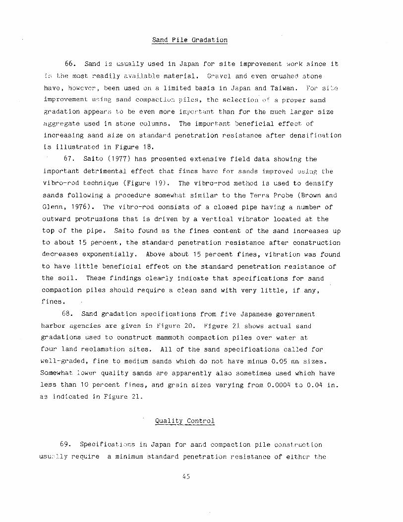
Sand Pile Gradation
66. Sand is usually used in Japan for site improvement woi'k since it
1~ the most readily available material. Gravel and even crushed stone
have, however, been used on a limited basis in Japan and Taiwan. For site
improvement using sand compaction piles, the selection of a proper sand
gradation appears to be even more important than for the much larger size
aggregate used in stone columns. The important beneficial effect of
increasing sand size on standard penetration resistance after densification
is illustrated in Figure 18.
67. Saito (1977) has presented extensive field data showing the
important detrimental effect that fines have for sands improved using the
vibro-rod technique (Figure 19). The vibro-rod method is used to densify
sands following a procedure somewhat similar to the Terra Probe (Brown and
Glenn, 1976). The vibro-rod consists of a closed pipe having a number of
outward protrusions that is driven by a vertical vibrator located at the
top of the pipe. Saito found as the fines content of the sand increases up
to about 15 percent, the standard penetration resistance after construction
decreases exponentially. Above about 15 percent fines, vibration was found
to have little beneficial effect on the standard penetration resistance of
the soil. These findings clearly indicate that specifications for sand
compaction piles should require a clean sand with very little, if any,
fines.
68. Sand gradation specifications from five Japanese government
harbor agencies are given in Figure 20. Figure 21 shows actual sand
gradations used to construct mammoth compaction piles over water at
four land reclamation sites. All of the sand specifications called for
well-graded, fine to medium sands which do not have minus 0.05 mm sizes.
Somewhat lower quality sands are apparently also sometimes used which have
less than 10 percent fines, and grain sizes varying from 0.0004 to 0.04 in.
as indicated in Figure 21.
Quality Control
69. Specifications in Japan for sand compaction pile construction
usu~J.ly require a minimum standard penetration resistance of either the
45
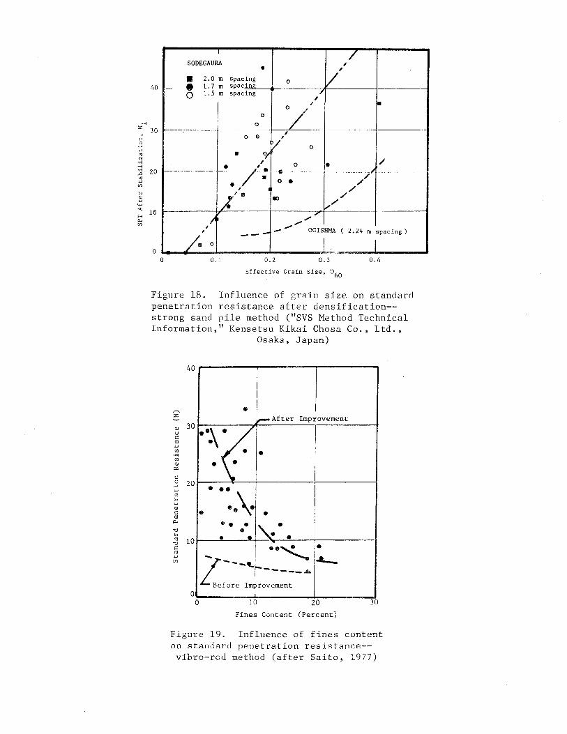
.-< z
" 0 •r-l w
"' N .... .-< .... ..0
"' w U1
'-' <!) w
4-< «: E-< p.. U1
I / SODEGAURA I • v' • 2.0 Ill spacing 0
- • 1.7m spacing -
0 l.Sm spacing / , 40
30
I .. • 0 0/ i
0
" ,
0
~/ 0
20
HJ
0
• .o/ , 0 • / • I • .. / • 0 // •
I /
fi'. ., / ,-/
,;, ,-' / -- OGISHMA ( 2.24 m spacing) I ---/· 0 I I
~·· ·-0 0.1 0.2 0.3 0.4
Effective Grain Size, o60
Figure 18. Influence of grain size on standard penetration resistance after densification-strong sand pile method ( 11 SVS Method Technical Information," Kensetsu Kikai Chosa Co., Ltd.,
~
z
(l)
u c "' ... Ul .... Ul (l)
ex: c 0 .... ... "' l-< w (l)
c: (l)
"" "0 l-<
"' ":)
c "' w
(/)
40
30
20
10
0 0
Osaka, Japan)
! I
• ~After Improvement
··~( • • •
. ·:.\ . I I I
• • •• • "-· .. • • •
- ··~ • ...__ ~---._ 1--- A
Before Improvem:~-1.0 20 JO
Fines Content (Percent)
Figure 19. Influence of fines content on standard penetration resistance-vibro-rod method (after Saito, 1977)
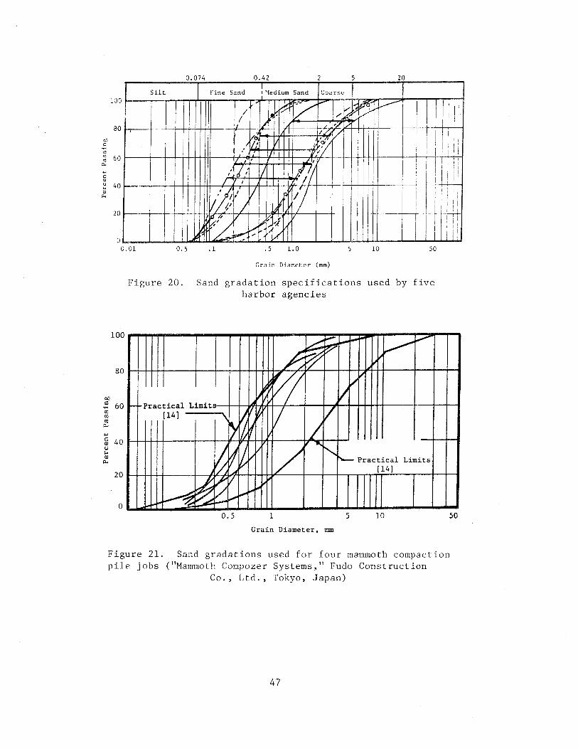
bO c:
.,.; rJ) rJ)
"' "'"' '"' c: (]) u .. (])
"'"'
0 074 0 42 2 5 20
Silt Fine Sand I 'ledium Sand Coarse
0.01 0. 5 . l . 5 l.O 5 10 so
100
80
60
40
20
0
Gr~in Diameter (mm)
Figure 20. Sand gradation specifications used by five harbor agencies
~ ~ ~ 1-~v
~
A ~ v
" ~
~~
vv ll f.- Practical Limits
rl~ l7 v [14) \~ ~ ~ /
~ ~ ? II / ~
i'-1/ I'-- Practical Limits
.A [14]
~ ~ v
~--~
--~ ~ :..,....... ,.,. I
o.s 1 5 10
Grain Diameter, mm
Figure 21. Sand gradations used for four mammoth compaction pile jobs ("Mammoth Compozer Systems," Fudo Construction
Co., Ltd., Tokyo, Japan)
47
so
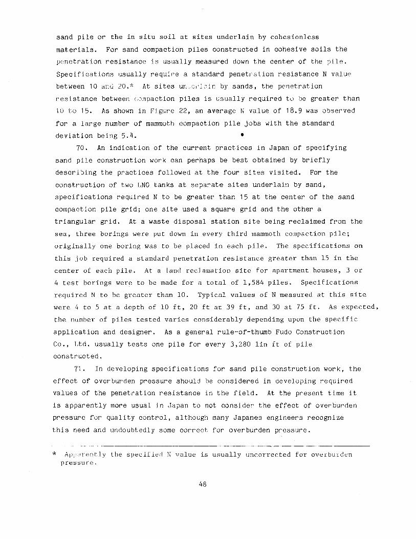
sand pile or the in situ soil at sites underlain by cohesionless
materials. For sand compaction piles constructed in cohesive soils the
penetration resistance is usually measured down the center of the pile.
Specifications usually require a standard penetration resistance N value
between 10 ancl 20.* At sites ur";-;,·J:1in by sands, the penetration
resistance between c.ompaction piles is usually required to be greater than
10 to 15. As shown in Figure 22, an average N value of 18.9 was observed
for a large number of mammoth compaction pile jobs with the standard
deviation being 5.4. • 70. An indication of the current practices in Japan of specifying
sand pile construction work can perhaps be best obtained by briefly
describing the practices followed at the four sites visited. For the
construction of two LNG tanks at separate sites underlain by sand,
specifications required N to be greater than 15 at the center of the sand
compaction pile grid; one site used a square grid and the other a
triangular grid. At a waste disposal station site being reclaimed from the
sea, three borings were put down in every third mammoth compaction pile;
originally one boring was to be placed in each pile. The specifications on
this job required a standard penetration resistance greater than 15 in the
center of each pile. At a land reclamation site for apartment houses, 3 or
4 test borings were to be made for a total of 1,584 piles. Specifications
required N to be greater than 10. Typical values of N measured at this site
were 4 to 5 at a depth of 10 ft, 20 ft at 39 ft, and 30 at 75 ft. As expected,
the number of piles tested varies considerably depending upon the specific
application and designer. As a general rule-of-thumb Fudo Construction
Co., Ltd. usually tests one pile for every 3,280 lin ft of pile
constructed.
71. In developing specifications for sand pile construction work, the
effect of overburden pressure should be considered in developing required
values of the penetration resistance in the field. At the present time it
is apparently more usual in Japan to not consider the effect of overburden
pressure for quality control, although many Japanes engineers recognize
this need and undoubtedly some correct for overburden pressure.
* Apparently the specified N value is usually uncorrected for overburden pressure.
48
....... "' 13
C) ...... 00
..>:: '-'
X Q)
"" c: H
Q)
c: 0 u
sor N 18.9 avg.
40 0 = 5. 4
[)' 20 c: QJ ::l cr ~ 10
""
5 SPT at Center of Pile
Figure 22. Observed variation in SPT value for
a large number of mammoth compaction pile ("Mammoth Compozer System," Fudo Construction
4 0.2
3 ....... 0.15
"' 13 () --2 00
..>:: 0.1 "'-'
.c: .., 00
1 ~ 0.05 ~ ..,
U'l
0 0
Co., Ltd., Tokyo, Japan)
Cone Index
0 2 4 6 8 10
Time in Honths
Shear Strength
14
Figure 23. Effect of sand pile construction on shear
strength as a function of time (after Ichirnoto, 1980)
49
Influence of Lateral Pressure on SPT Value
72. Construction of sand compaction piles typically results in
standard penetratio~ resistances increasing by a factor of ? to 5 as shown
in FiRure 13 and 14. Babed on extensive field measurements made at the
Ogishiwa Island Steel Plant, Saito (1977) has concluded that the large
measured increase in standard penetration resistance is not accompanied by
a corresponding large increase in relative density. As a result, the
relative density obtained when the measured N value is corrected for
overburden pressure was found to considerably over-estimate the actual
relative density of the improved soil at the Ogishima site. The
misleadingly large standard penetration resistances measured after site
improvement is attributed to the significant increase of lateral prFssure
during densification of the sand. Pressuremeter measurements indicated an
increase in K0 from about 1 to as much as 6. The important effect of
lateral stress on standard penetration resistance has been previously
reported (Rodenhauser, 1974; Zolkof and Wiseman, 1965; Schmertmann, 1975).
More research is certainly needed to develop techniques for handling the
effect of lateral pressure increase on relative density.
Strength Loss Due to Sand Pile Installation
73. Construction of sand compaction piles in cohesive soils causes a
significant loss of strength due to remolding of the soil surrounding the
pile (Figure 23). As pore pressures dissipate the shear strength of the
clay gradually increases, with the time required to regain its initial
strength depending to a great extent upon the physical-chemical
characteristics of the soil. Field measurements in Japan indicate that
typically from 2 to 20 weeks are required to regain initial strength with 2
to 3 weeks perhaps being more usual (Ichimoto, 1980; Aboshi et al., 1979).
For mammoth compaction piles the effect of remolding is even more severe
than for sand compaction piles, but strength gain has still been observed
(Ichimoto, 1980).
74. Ichimoto (1980) recommends waiting in cohesive soils at least a
month before loading sand compaction piles to allow at least a partial
50
recovery of initial strength. Further, when constructing sand compaction
piles in granular soils, the existance of a clay seam or even a relatively
impArvious fine sand ~ ·n, will prevent the N-value from increasing until
some time after construction. Therefore, if low pArmeability layers are
present the st~tdard penetration resistance should not be measured until as
long as possible after construction (Icliimoto, 1980).
75. In constructing sand compaction piles in very soft clays, loss of
strength due to remolding can be an important problem. To overcome this
problem, sand having a high angle of internal friction should be used or
else the construction should be organized in stages (Ichimoto, 1980). For
stage construction, first place the piles at twice the final spacing and
later, after strength gain has occurred, install a second series of piles
midway between the piles previously constructed.
76. Sand compaction piles are vibrated into the ground. As a result
important shear stresses are transferred to the surrounding soil. Also
"smear" of the native soil occurs adjacent to the sides of a sand
compaction pile. Field studies show that when a pipe is pushed into the
ground without jettying, a significant reduction in lateral permeability
occurs; the effect of smear is much less; however, when the pipe is jetted
into the ground (Barksdale and Bachus, l983(a); Casagrande and Poulos, 1968).
Since stone columns are usually jetted into the ground, smear effects and
the remolding of the surrounding soil is much less than in sand compaction
pile construction.
51
PART V: SUMMARY AND CONCLUSIONS
77. The primary use of sand compaction piles in Japan is to prevent
stability failures. When settlement is of concern, preloading is often
used after the sand compaction pilPs have been constructed. Sand
compaction piles are used extensively in Japan to suppo; :. dikes,
embankments for roads and railways, stockpiles of heavy materials and tanks.
Embankments are routinely successfully constructed on cohesive soils with
shear strengths varying from 200 to 300 psf that have been reinforced with
sand compaction piles.
78. Sand compaction piles are constructed by driving a steel casing
(pipe) filled with sand to the desired elevation using a heavy vertical
vibrator placed at the top of the pile. The casing is then gradually
extracted using a stroking motion to densify the sand. Using this
construction sequence, soft cohesive soils surrounding the pile ar·e not
left partially unsupported as is usually the case during the construction
of stone columns. Also sand compaction piles are constructed by dumping
sand down the casing and not down an uncased hole as occurs during stone
column construction. Since jetting is not normally used, construction of
sand compaction piles does not result in a large quantity of excess muddy
water which is often environmentally objectionable in stone column
construction. Erosion of fines into the sand compaction pile should not be
a problem for normally used gradations of sand. Finally, construction of
sand compaction piles, which is fast and efficient, utilizes low-cost,
often locally available sand.
79. The important disadvantages of using sand compaction piles to
prevent stability failures of embankments appears to be (a) sand has a
lower angle of internal friction than the large size stone used in stone
columns and hence requires a larger area replacement ratio, (b) smear and
remolding effects are greater for sand compaction piles than stone columns
and, (3) contractors in the United States do not have either the experience
or mechanized equipment for rapidly constructing sand compaction piles.
Finally, sand piles would not act as vertical drains during an earthquake.
For many applications these disadvantages are not serious. Several
different vertical vi~·ators are presently available in the United States
that could be used to construct sand compaction piles. The automatic skip
52
loading system used in Japan and Taiwan could be imported from Japan, or
else a similar system (or even a simple version) could be designed and
constructed in the United States.
80. Typically approximately 80 percent of the consolidation
settlement occurs in a cohesive soil reinforced with sand compaction piles
within about 8 months from the beginning of construction. Therefore, an
important part of the settlement due to an embankment should be complete by
or shortly after the end of construction; consolidation of stone column
improved ground should progress somewhat faster. Because of the lower cost
of sand and faster production rates, sand compaction piles constructed in
the United States using efficient equipment similar to that employed in
Japan should cost about 1/2 to 2/3 the cost of stone columns. For many
applications involving, for example, stability of embankments, sand
compaction piles offer a quite viable alternative to stone columns.
Therefore on appropriate projects alternate bids and/or demonstration type
projects should be used to encourage the development of sand compaction
pile technology in the United States.
53
REFERENCES
Aboshi, H., et al. 1979. "The Compozer - A Method to Improve Characteristics of Soft Clay by Inclusion of Large Diameter Sand Column," Proceedings, International Conference on Soil Reinforcement, ReinfGrc~d Earth and Other Techniques, Vol. I, Paris, p. 211-216.
1.\aLun, N. P., and Booker, J. R. 1979. "And] ysis of Rigid Rafts Supported by Granular Piles,'' The University of Sydney, Report 339, School of Civil Engineering, January.
Barksdale, R. D., and Bachus, R. C. 1983a. "Design and Construction of Stone Column," Vol. I, Federal Highway Administration, Report FHWA/RD-83/026, 210 p., December.
1983b. "Design and Construction of Stone Columns," Draft Report, Federal Highway Administration, February.
Brown, R. E., and Glenn, A. J. 1976. "Vibroflotation and Terra-Probe Comparison," Geotechnical Journal, ASCE, Vol. 102, No. GTlO, October._
Casat,rande, L. and Poulos, S. 1968. "On the Effectiveness of Sand Drains," Canadian Geotechnical Journal, Vol. 6, pp 287-326.
Delapierre, J., Van Den Poel, J., and Wallays, M. 1980. Amelioration. Mechanique En Profondeur Des Sols Meuhanische Die ptev erdichting, Pieux Franki - Liege.
Hayashi, K. 1981. Personal communication with Mr. K. Hayashi, Managing Director, Kensetsu Kikai Chosa Co., Ltd., Osaka, Japan, March.
Holtz, W. G., and Gibbs, H. J. 1957. "Research on Determining Density of Sands by the Split Spoon Penetration Test," Proceedings, 4th International Conference on Soil Mechanics and Foundation Engineering.
Ichimoto, A. 1980. "Construction and Design of Sand Compaction Piles," Soil Improvement, General Civil Engineering Laboratory, Vol. 5, June, (in Japanese).
Ladd, C. C., and Foott, R. 1977. "Foundation Design of Embankments Constructed in Varved Clays," FHWA TS-77-214, Federal Highway Administration, May.
Leonards, G. A. (Editor). 1962. Foundation Engineering, lst Ed., McGrawHill, Inc., New York.
Mizutani, Y. 1981. Personal Communication with Mr. Y. Mizutani, President, Kensetsu Kikai Chosa Co., Ltd., Osaka, Japan, March.
Ogawa, M., and Ishida, M. 1965. "The Vibro Compozer Method as Applied to Compaction of Sand Foundation Soils," Soil and Foundation, Vol 13, No. 2, (in Japanese).
Rodenhauser, J. 1974. "The Effect of Mean Normal Stress on the Blow Count of the SPT in Dense Chattahoochee Sand," Duke University, Project Report.
Saito, A. 1977. Sandy Deposit and Foundations, Vol.
"Characteristics of Penetration Resistance of a Reclaimed Their Change Through Vibratory Compaction," Soils and 17, No. 4, December, p. 31-43.
54
Schmertmann, J. H. 1975. "The Measurement of Insitu Shear StrengthState-of-the-Art Presentation to Session 3," Proceedings, ASCE Specialty Conference on Insitu Measurements of Soil Properties, Raleigh, Vol II, pp. 57-138.
Tanimoto, Kiichi. 1973. "Introduction to the Sand Compaction pile Method as Applj r:d to Stabilization of Snft Foundation Grounds," Division of AppJ j Pd Geomechanir:s GSIRO, Technical Report No. 16, Austrc:iia.
US Army Corps of Engineers. 1970. "Engineering and Design Stability of Earth and Rock-Fill Dams," Department of the Army Engineer Manual El'I 1110-2-1902.
Zolkof, E., and Wiseman, G. 1965. "Engineering Properties of Dune and Beach Sands and the Influence of Stress History," Proceedings, 6th International Conference on Soil Mechanics and Foundation Engineering.
55