Embed Size (px)
Citation preview
~
LAUNCH & RETRIEV ALMETHODS
011 Stream
Entry Exit
-Tee
I Pigmr& CatcherI Basket
J' 11- - - - - :..t
------ID---ID -
II I Entry Exit
Irl Wye
I 1 I
I II' - - - -I
I I Entry Exit
I I I r---o Fire Hydrant [WIt)I.
II I
!It CIooed1It - - - - --Entry. Exit
Spool Piece
- - - . . - - - - -Entry Exit
,
r
Figs. 7, 8, 9
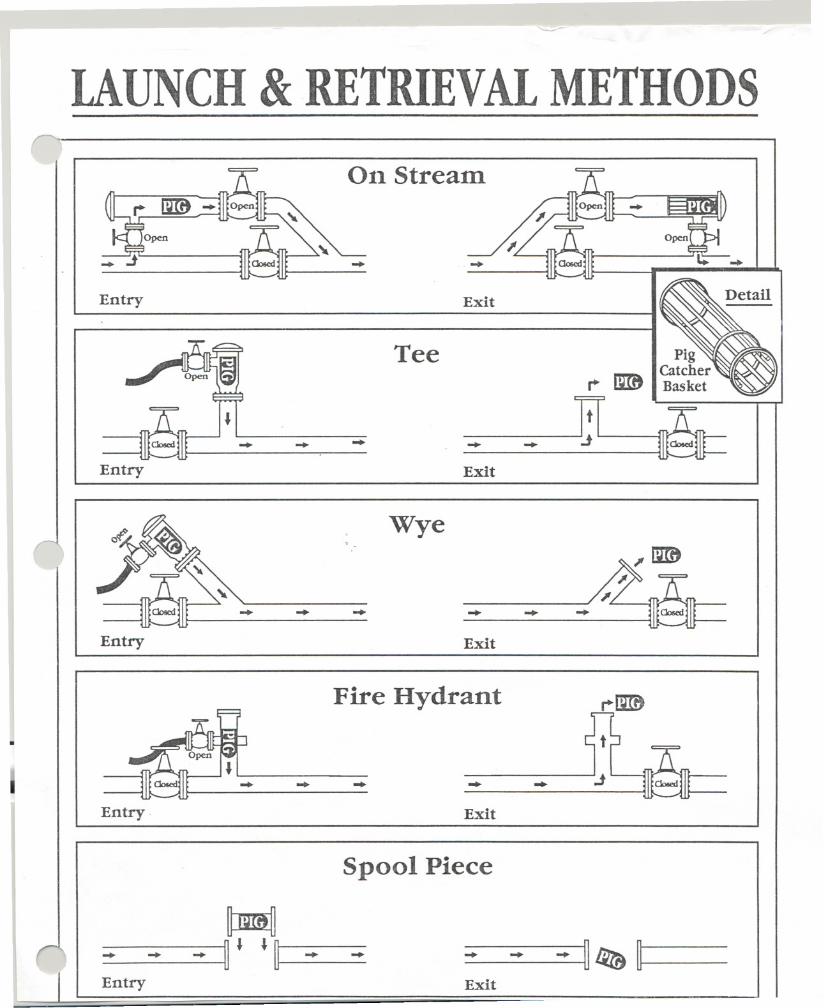
Spheres
Gas service - Fig.9
--launcher
1. Close Valves A, B, D, and C.
2. Blow-down the launching trap through blow-down Valve C.
3. When the trap is completely "blown down, open the closure door andinsert the required number of spheres.
4. Close the closure door and open vent Valve D. Purge the launcherbarrel through vent Valve D by slowly opening equalizer Valve B. Whenpurging is completed, close vent Valve D.
5. Allow the trap to equalize to line pressure.
6. Open equalizer Valve B, then trap Valve A. The spheres are nowready for launching.
1 pipe diameter
tNote: Angle 8 will be selected based on size of pipeline system, service, andoperation procedures.
Receiver
~
1. If trap purging is necessary, close Valve A and B and open ventValve D and purge by opening drain Valve B.
2. After purging, close vent Valve D and allow trap pressure to equalizeto line pressure.
3. Open Valves A and B. Trap is ready to receive spheres.
4. When the receiver barrel fills up with spheres, close trap Valve Aand drain the barrel through the drain Valve 8.
5. Close drain Valve B and blow the trap down through blow-downValve C.
6. Open the closure door and remove the spheres.
7. Close the closure door. Purge the trap as described in Item 1 andequalize the trap to line pressures; then open Valves A and 8 far operation.
THE OILAND GAS JOURNAL-NOY. 27, 1978
WSI-6-9
Iweld and on receiver traps 1¥2-times.the length of the pig from the bypassline to the closure weld.
A short pup is placed between thereducer and the trap valve to providehead space for the pig. This pup pre-vents the steel nose of the pig fromcoming into contact with the trapvalve during pressurization. If con-tact is made with sufficient pressuredifferential, the pig may damage thevalve.
In the case of large-diameter landpipelines transporting natural gas,crude oil, or refined products, thetrap valve and side valve should beburied with the barrel above ground.This will provide additional headspace on the barrel. This extra lengthis especially necessary on receivingtraps.
In gas service, the velocities atreceiving traps can exceed 30 mph.The extra head space is required tostop the pig and prevent it fromhitting the closure door.
The bypass line is attached to thebarrel near the closure on launchingtraps and near the reducer on re-ceiver traps. 'The size of the bypassvaries with service, but the diameteris usually a minimum of 22% of thepipeline diameter.
Pig indicators should be located onthe barrel pup joint near the reduceron receiving traps, and downstreamof the side valve tee on launchertraps. The pig indicator should belocated on top of the pipe to preventforeign material from making theindicator inoperative.
Liquid pipelines require a drain onthe barrel along with a pressuregauge, thermal-pressure relief valve,and vent valve. The drain valveshould be located in the verticalposition directly under the barrel.This is to prevent an accumulationof material from plugging the drainand making the drain valve inopera-tive.
Gas-pipeline pig traps require ablowdownvalve, pressure gauge, anda utility or vent valve. Large-diam-eter pipelines usually require a liftingdevice to load and unload pigs. Thedevice is usually installed when thepigs exceed 100 lbs. The device con-sists of a swivel loading arm equippedwith a chain hoist or come-along.
Procedures for launching and re-ceiving pigs in various services is in-cluded (Figs. 7 and 8) to demonstratethe general practice. This proceduremay vary from pipeline to pipelinebecause of the unique circumstancesof each pipeline system and combina-tions of services.
Concerning the procedure forlaunching and receiving pigs in gas
Tl.
-
service (Fig. 7), note that Valves E,F, and D on launcher traps and ValveE on receiver traps are used only inlarge-diameter land-pipeline servicewith buried valves. Th~se valves pro-vide an extra margin of safety forpurging and pfttecting the valve gatefrom damage. For small-diameterpipelines and in restricted areas, thesevalves can be eliminated. This is adecision of the operator.
Sphere launchers. Sphere launchersdiffer from pig launchers becausethey are equipped with extra-lengthbarrels for multiple launchingY"These extra length barrels are calledmagazines. This feature of spheresmakes them readily adaptable to un-manned launching.
The operator can load the magazinewith several spheres, and the launch-ing can be activated either automati-cally or remotely. This process isused extensively in two-phase-flowpipelines in remote areas.
Various launching mechanisms areavailable on the market so the selec-tion of launchers is a matter ofchoice. Launchers consist of checkvalves, ball valves with only one sideof the ball cut out, pins, and rockermechanisms.
Additional valves are sometimes in-stalled downstream of the launchingmechanism to facilitate repairs on thelauncher without shutting down thepipeline system.
The launcher will consist of thelauncher barrel, launching mechan-ism,. isolation valve, equalizer valveand reducer tee. The receiver willconsist of a barrel, isolation valve,reducer tee and a drain that will suf-fice as an equalizer line (Fig. 9).
Both launcher and receiver shouldbe equipped with a pressure gauge,blow-down, and utility valve. Pig in-dicators are installed on the launcherdownstream of the side-tee reducerand on the receiver just upstream ofthe tee.
A sphere-launcher barrel or maga-zine will hold several spheres readyfor launching. The length of the maga-zine depends upon the frequency ofrunning spheres and the frequencyof reloading.
In remote areas such as offshoreplatforms that are affected byweather, a safety factor should beincluded in the event the reloadingschedule cannot be met and piggingmust be maintained to prevent shut-down of facilities.
Large magazines can become toolong or tilted at an excessive angle,causing excessive weight on the bot-tom sphere. This will cause thespheres to bind and the release mech-anism to malfunction.
~
78
\0181-6-10
The author. . .Brian (Butch) Webb isa senior staff engineerwith Crest EngineeringInc., Tulsa, Okla. From1974 to the present hehas worked for Crest,primarily on overseasjobs in Indonesia andIraq. Prior affiliationsinclude design engi.neer for Williams Bros.Engineering Co., north-ern division engineerfor Trunkline Gas Co.,as-built engineer for Fish Service, and welderhelper for Brown& Root. Webb holds a degreein petroleum engineering from OklahomaStateUniversity (l957).
BrianWebb
To prevent this, the magazine angleshould be reduced to cause the maga-zine walls to absorb most of theweight of the spheres. A recommend-ed angle for the magazine is shownin Table 2.
Table 2
Launcher, magazineangles
Angleoflauncher
Nominal mechanism,diameter,in. degrees
Angleofmagazines,
degrees
15105
4 to 810to 20
, 22to 48
452020
The diameter of the launcher andreceiver barrels for sphere service is2 in. larger than the diameter of theline pipe. The barrels can usually hold10 spheres and have been known tohold 15 spheres.
For convenience of loading and un-loading, the closure-door hinge shouldalways be in the vertical to enablethe operator to open and close thedoor without the aid of extra equip-ment. The receiver barrel should havea horizontal pup near the closurewhich is one diameter in length.
The blow-downon the launcher andreceiver barrels should be near the.highest point on the barrel. Thiswould be near the closure on thelauncher and at the valve on the re-ceiver. Likewise on the receiver bar-rel, the drain should be at the lowestpoint. The drain should tap into thebarrel in two places to prevent thespheres from rolling over the drainand stopping flow.
The two drains should be apart adistance of one-half to three-fourths
~the \;phere diameter. The equalizerline and valve on thp launcher can belocated at operator's convenience.
Hoisting mechanisms should beavailable to facilitate loading and un-loading spheres when the pipelinediameter is 20 in. or larger.
Combination sphere and pig launch-ers can be designed for special con-ditions where spheres are required forliquid control and pigs are requiredfor periodic cleaning operations.
Fig. 9 gives the procedure forlaunching and receiving spheres ingas service. For liquid service, cer-tain modifications must be made fordraining the barrels. to prevent spill-age when the closure doors areopened. The operation is basically thesame as that for gas service.
AcknowledgmentsThe author wishes to express ap-
preciation for information obtainedfrom various people with experienceand knowledge in the pipeline indus-try, including Clinton McClure, Wil-liams Bros. Engineering Co.; DelMoore, Wheatley Co.; Jim Forster,Tom Wheatley Co.; Larry Payne, T.D. Williamson Co.; Bill Fulton, Ex-plorer Pipeline; and Frank Gray,Girard Polly-Pig Inc.
ReferencesI. Oranje, L, "Condensate Behavior in
Gas Pipelines is Predictable," OGJ, July 2,1973.
2. Lauer, Thomas W., "ConsolidatedUses a New Breed of Pigs in its Pipelines,"Gas, September 1968.
3. Moon, L B., "Putting A New.Prod-ucts Line into Operation," API Paperpresented at Philadelphia, Pa., May 10,1954.
4. Olson, A. S., "Detergent Cleaning aMountain Pipeline," Pipeline Industry,September 1956.
5. McClure, C, "Soap and Water CleanDirty Pipelines Too," OGJ, July 4, 1955.
6. McClure, C, "Cleaning InternallyCoated Lines After Construction and Test-ing," Pipeline Industry, Jan. 1, 1960.
7. Powers, Marvin D., "Super Dry Airis Used to Pig Pipeline and Dry Th1Jm,"OGJ, May 24, 1976.
8. Popan, Victor A, "Cleaning and Dry-ing Pipelines Part I Efficiency Improve-ment," Pipeline and Gas Journal, January1978.
9. Hess, C Frederick, "Methanol Swab-bing Technique Used to Dry Frigg GasLines," Pipeline Industry, January 1978.
10. McDonald, A. E., and Baker, Ovid,"Multiphase Flow in Pipelines, Part I, 2, 3,4," OGJ, June 15, 1974.
11. Palmer, C. M., "Pigging and the Useof Slug Catchers in Offshore Gas Pipe-lines," Tulsa University Fluid Flow Projects,May 1974.
12. Powell, J. C, and Senatoroff, N. K.,"Hydrostatic Testing: Economies, Problemsand Procedures," Gas, January 1954.
13. "Guide to Pigging," T. D. William-son, Inc., Tulsa, Okla.
14. Whipple, L Frank, "How to DesignOnstream Pigging Facilities," Pipeline In-dustry, June 1966.
15. Wheatley Company', "Sphere Launch-ing and Receiving Equipment."
THE OIL AND GAS JOURNAL - NOV. 27, 1978
~-
I
I
I
I
I
I I
I..I
~
I
TULSA,
,tIJUN
"
~
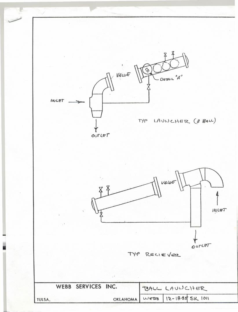
V/JLV(;\
+Oc.JTI..r: r
T)'f' LAvW L\-\ E R- ($ 84Ll.)
. .
fIAJLt1T
"
f(;) a ,I..f!T
"If> RJcc..\ E; Val-
. .
WEBB SERVICES INC. 1.'3AL,L. LA \J 0 c.. \-\-~
OKLAHOMAI w~'\!
HOFF COMPANY, INC.
cp
...~..-~....-./" -- '-. ..'...,..
.' ~ .'. -",
t
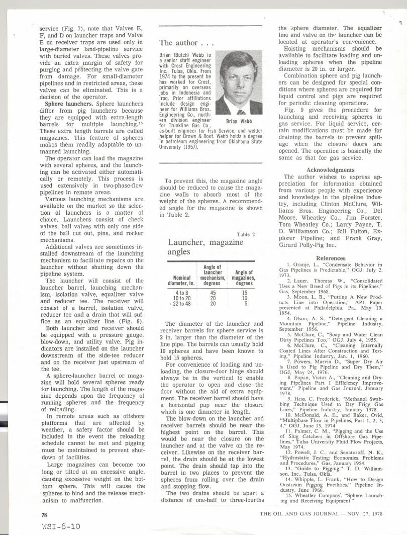
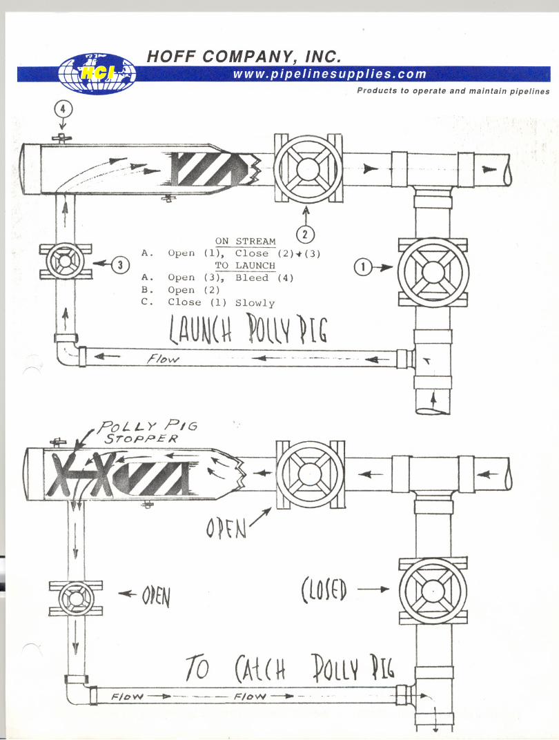
ON STREAM ~Open (1), Close (2)-+(3)
TO LAUNCHA. Open (3), Bleed (4)B. Open (2)C. Close (1) Slowly
lAUM("~ll~ )1'
~
.~",-~. "~---'."- - . .....-'-11,,- rIbv.!'
?OL '- Y PIGSroPPE R
...-
~
~ O~tN (lO{E~
~i
(At ( H ~QlL~ ll'70FIDW ---tI ~-- FIDW --. -.. .-
.....
'.
....
......-
HOFF COMPANY, INC.
JI
@:
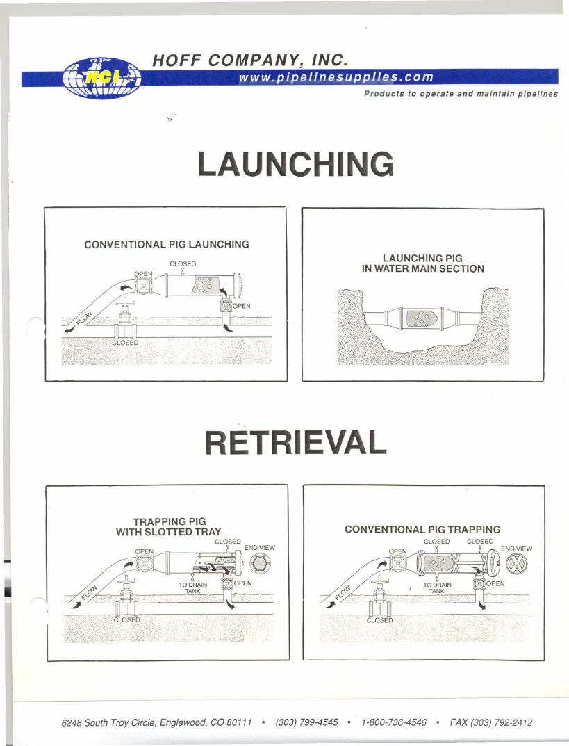
LAUNCHING
CONVENTIONAL PIG LAUNCHING
CLOSED LAUNCHING PIGIN WATER MAIN SECTION
~
II
: IIII
RETRIEVAL
~
TRAPPING PIGWITHSLOTTED TRAY
CLOSEDEND VIEW
CONVENTIONAL PIG TRAPPINGCLOSED CLOSED
~
6248SouthTroyCircle,Englewood,CO80111 . (303)799-4545 . 1-800-736-4546 . FAX(303)792-2412
HOFF COMPANY, INC.
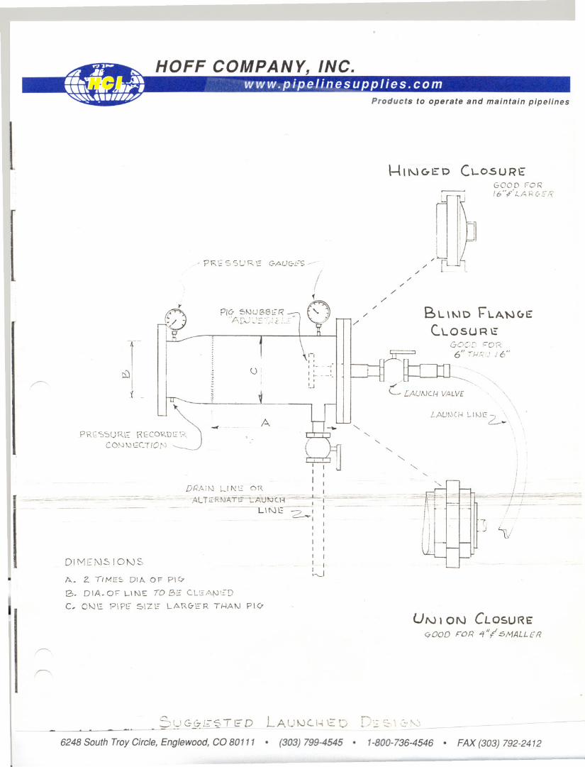
- PR E S SU R \2 G-AU(jL'-S /
/(~
PI~F,~:~~~-~~~-~ ()
~J
I
t -I I U --------
PReSSURE ReCORD~ --CON\,)GCTIO,~'J ~J
~ U!
nI' -I,I ,- -,I :- - _:-I I!.J
A
~ "" C7E D C\.-O5U REGOOD FoR/6"#" LA PC.ER
/'/
/'
/'
/
/'
/'BL \t-..\D1="LANuE
c.LOSUR ~1200[' FOR6" iJ..!r-i,) i 6"
/~--:.C [AUI\JCf.4 V,<:I,LV[ .
.... ""-'-..
'-..'-..
\\ .
LAUk\CH \..-11-.11::~ .,
11- ~I II
--- --~~- - - DR;';iN LI ~~c_o~ ~-'- '..: . .-~--,~.",",-",,~=. .,=" ~ -""'~--'=~~--'"'" ALTEi\"'i.J'AT"~A1j!I:YC:H'~"'"7f =~~'~',-~
- ~- -" --I ---- LINE -./ I
. c:.--v I II II II II fI I,- f
~DI MEi\)S IONS
. A. Z liME=:' DIA OF PIC7
B- DIA. 01="1-' ~\E TO BE c.LEAN~!)
C, ONE PiPt=" S\Z1.: LAR0ER T/...jAt-J P\<?,
r---
,,--..
S U G (7 f~-;' T_E D LA U !>Jc. I.., "::: D
6248 South TroyCircle,Englewood, CO 80111 . (303) 799-4545 .
- -----
""-""-
'-'-....
'7 .
.J ~i
UN t ON CLOSURE<:7000 FOR 4"( SMALLJ:f?
D":: ~ '; ,~:' \:\ ~
1-800-736-4546 . FAX (303) 792-2412