Embed Size (px)
Citation preview
SUPPLY OF PIG LAUNCHER/RECEIVERFOR SULTANPUR-JHAJJAR-HISSARPIPELINE (SJHPL) PROJECT Project No : P.013312Document No : P.013312 D11031 003E-Tender No : 8000014930
Gail (India) Limited Noida, INDIA
PUBLIC
06 August 2019
TECHNICAL DOCUMENTATIONTechnical, Vol II of II, Rev 0
S.No. Document/ Drawing No. Rev. No. Pages Page No.
I VOLUME I OF II
1
2
3
4
5
II VOLUME II OF II
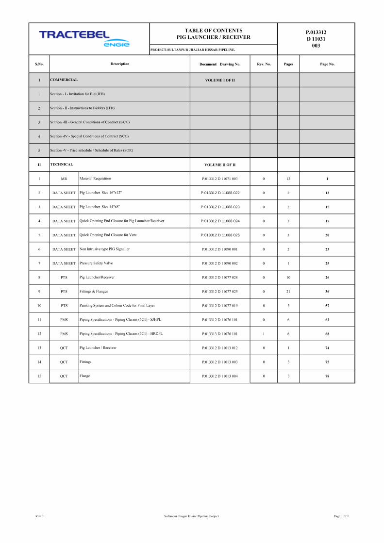
1 MR P.013312 D 11071 003 0 12 1
2 DATA SHEET P.013312 D 11088 022 0 2 13
3 DATA SHEET P.013312 D 11088 023 0 2 15
4 DATA SHEET P.013312 D 11088 024 0 3 17
5 DATA SHEET P.013312 D 11088 025 0 3 20
6 DATA SHEET P.013312 D 11090 001 0 2 23
7 DATA SHEET P.013312 D 11090 002 0 1 25
8 PTS P.013312 D 11077 028 0 10 26
9 PTS P.013312 D 11077 025 0 21 36
10 PTS P.013312 D 11077 019 0 5 57
11 PMS P.013312 D 11076 101 0 6 62
12 PMS P.013313 D 11076 101 1 6 68
13 QCT P.013312 D 11013 012 0 1 74
14 QCT P.013312 D 11013 003 0 3 75
15 QCT P.013312 D 11013 004 0 3 78
Quick Opening End Closure for Vent
Section - II - Instructions to Bidders (ITB)
Section -V - Price schedule / Schedule of Rates (SOR)
P.013312
D 11031
003
COMMERCIAL
Description
Section - I - Invitation for Bid (IFB)
TABLE OF CONTENTS
PIG LAUNCHER / RECEIVER
PROJECT-SULTANPUR JHAJJAR HISSAR PIPELINE.
Material Requisition
Piping Specifications - Piping Classes (6C1) - SJHPL
Pig Launcher/Receiver
Fittings & Flanges
TECHNICAL
Section -III - General Conditions of Contract (GCC)
Section -IV - Special Conditions of Contract (SCC)
Pig Launcher Size 16"x12"
Quick Opening End Closure for Pig Launcher/Receiver
Pig Launcher Size 14"x8"
Flange
Non Intrusive type PIG Signaller
Pressure Safety Valve
Painting System and Colour Code for Final Layer
Pig Launcher / Receiver
Fittings
Piping Specifications - Piping Classes (6C1) - HRDPL
Rev.0 Sultanpur Jhajjar Hissar Pipeline Project Page 1 of 1
MATERIAL REQUISITION FOR PIG
LAUNCHER/RECEIVER
P.013312
D 11071
003
SULTANPUR JHAJJAR HISAR PIPELINE (SJHPL) PROJECT
TRACTEBEL ENGINEERING PVT. LTD.
MATERIAL REQUISITION FOR PIG LAUNCHER / RECEIVER
0 23.07.2019 Issued for Procurement SSA MS AR
Rev. Date Description Prepared by Checked by Approved by
Page 1 of 82
MATERIAL REQUISITION FOR PIG
LAUNCHER
P.013312
D 11071
003
Rev. 0 Sultanpur Jhajjar Hissar Pipeline (SJHPL) Project. Page 2 of 12
TABLE OF CONTENTS
1. INTRODUCTION ................................................................................................................. 3
2. DEFINITIONS ..................................................................................................................... 3
3. DESCRIPTION OF GOODS ADD/OR SERVICES AND OTHER DOCUMENTS REQUIRED
FOR FLOW TEE ........................................................................................................................... 4
Page 2 of 82
MATERIAL REQUISITION FOR PIG
LAUNCHER
P.013312
D 11071
003
Rev. 0 Sultanpur Jhajjar Hissar Pipeline (SJHPL) Project. Page 3 of 12
1. INTRODUCTION
GAIL (India) Limited is planning to lay a 135.00 kms (approx.) Natural Gas Pipeline, with Dispatch Station (DT)
at Sultanpur in Haryana State and Receipt Station (RT) in Hisar District of Haryana State. This proposed pipeline
is hereinafter referred to as Sultanpur-Jhajjar-Hisar Pipeline (SJHPL).
The Pipeline Size has been finalized as 12” NB, with a total Flow capacity of 1.00 MMSCMD (0.5 MMSCMD for
Hisar, and 0.5 MMSCMD for Jhajjar).
The 135.00 km Mainline from Sultanpur to Hisar shall have a Dispatch Station (DT) at Sultanpur, a Receiving
Station (RT) at Hisar, an IP Station (IP) at Chainage 69.8 Kms (approx.) and Four (4) nos. of Sectionalizing Valve
(SV) Stations along the route, with a Tap-Off for Jhajjar CGD at SV-1. The Pipeline shall be piggable.
TE-India is now inviting tenders on Limited Domestic Competitive Bidding basis for procurement of Pig
Launcher/Receiver for this project.
The present document covers the technical specifications for this procurement enquiry. It forms an integral part
and is to be read in conjunction with ‘Volume I of II: Commercial
2. DEFINITIONS
Client Shall mean GAIL (India) Ltd;
Engineer/Owner’s Representative Designate the individual or legal entity to which the
Owner has entrusted various tasks in relations with
the carrying-out of his project. This also includes
PMC (Project Management Consultant) of the
Project;
Manufacturer Manufacturer of the Pig Launcher/Receiver (Bi-
directional type) as well as its sub-contractor(s).
Third Party Inspection Agency (TPIA) Means the Inspection Agency to be appointed by
Client / Client Approved TPIA.
Control Authority Client / Client’s Representative or Client’s Approved
TPIA.
Page 3 of 82
MATERIAL REQUISITION FOR PIG
LAUNCHER
P.013312
D 11071
003
Rev. 0 Sultanpur Jhajjar Hissar Pipeline (SJHPL) Project. Page 4 of 12
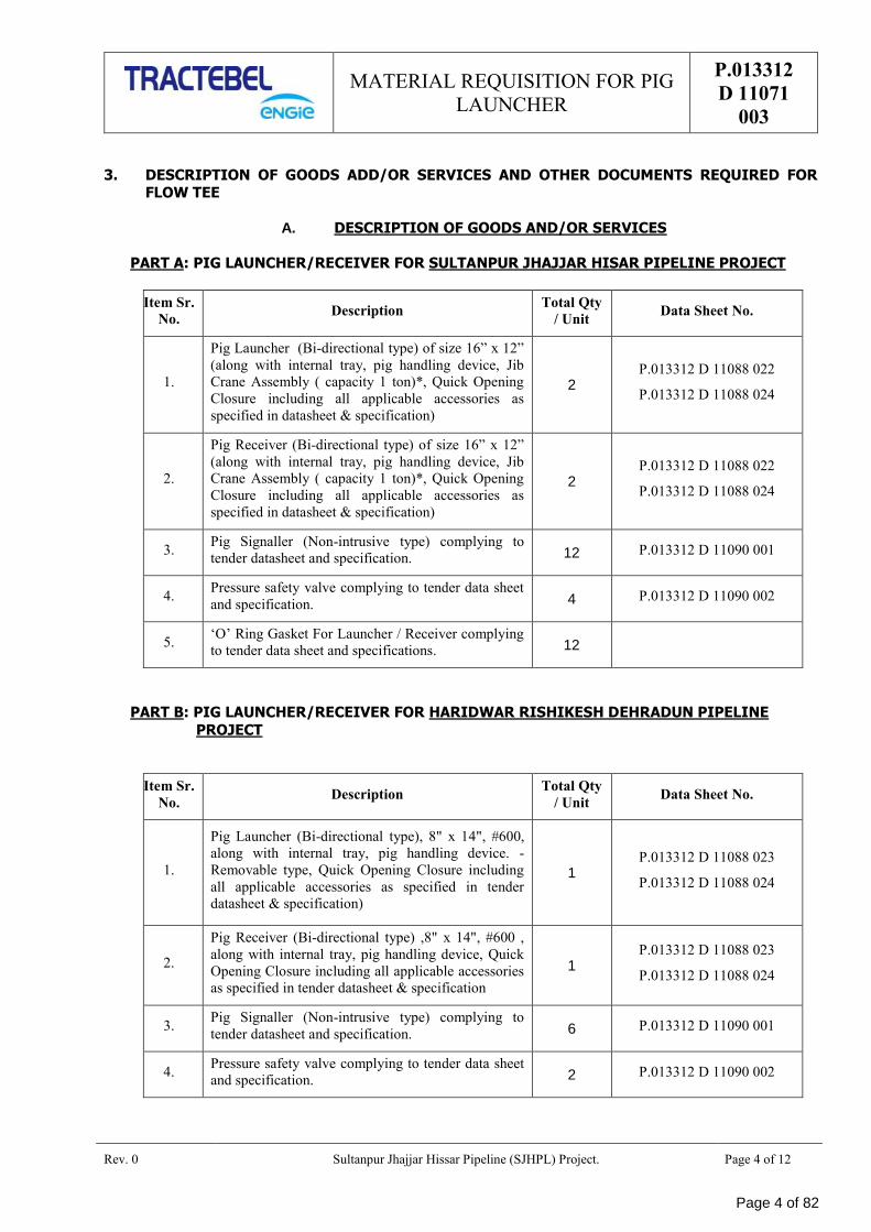
3. DESCRIPTION OF GOODS ADD/OR SERVICES AND OTHER DOCUMENTS REQUIRED FOR FLOW TEE
A. DESCRIPTION OF GOODS AND/OR SERVICES
PART A: PIG LAUNCHER/RECEIVER FOR SULTANPUR JHAJJAR HISAR PIPELINE PROJECT
Item Sr.
No. Description
Total Qty
/ Unit Data Sheet No.
1.
Pig Launcher (Bi-directional type) of size 16” x 12”
(along with internal tray, pig handling device, Jib
Crane Assembly ( capacity 1 ton)*, Quick Opening
Closure including all applicable accessories as
specified in datasheet & specification)
2 P.013312 D 11088 022
P.013312 D 11088 024
2.
Pig Receiver (Bi-directional type) of size 16” x 12”
(along with internal tray, pig handling device, Jib
Crane Assembly ( capacity 1 ton)*, Quick Opening
Closure including all applicable accessories as
specified in datasheet & specification)
2 P.013312 D 11088 022
P.013312 D 11088 024
3. Pig Signaller (Non-intrusive type) complying to
tender datasheet and specification. 12 P.013312 D 11090 001
4. Pressure safety valve complying to tender data sheet
and specification. 4 P.013312 D 11090 002
5. ‘O’ Ring Gasket For Launcher / Receiver complying
to tender data sheet and specifications. 12
PART B: PIG LAUNCHER/RECEIVER FOR HARIDWAR RISHIKESH DEHRADUN PIPELINE
PROJECT
Item Sr.
No. Description
Total Qty
/ Unit Data Sheet No.
1.
Pig Launcher (Bi-directional type), 8" x 14", #600,
along with internal tray, pig handling device. -
Removable type, Quick Opening Closure including
all applicable accessories as specified in tender
datasheet & specification)
1 P.013312 D 11088 023
P.013312 D 11088 024
2.
Pig Receiver (Bi-directional type) ,8" x 14", #600 ,
along with internal tray, pig handling device, Quick
Opening Closure including all applicable accessories
as specified in tender datasheet & specification
1 P.013312 D 11088 023
P.013312 D 11088 024
3. Pig Signaller (Non-intrusive type) complying to
tender datasheet and specification. 6 P.013312 D 11090 001
4. Pressure safety valve complying to tender data sheet
and specification. 2 P.013312 D 11090 002
Page 4 of 82
MATERIAL REQUISITION FOR PIG
LAUNCHER
P.013312
D 11071
003
Rev. 0 Sultanpur Jhajjar Hissar Pipeline (SJHPL) Project. Page 5 of 12
Item Sr.
No. Description
Total Qty
/ Unit Data Sheet No.
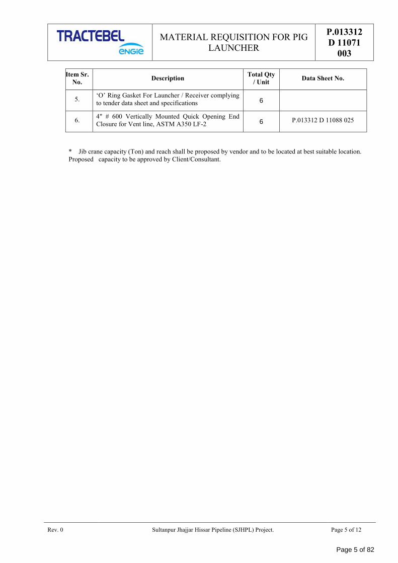
5. ‘O’ Ring Gasket For Launcher / Receiver complying
to tender data sheet and specifications 6
6. 4" # 600 Vertically Mounted Quick Opening End
Closure for Vent line, ASTM A350 LF-2 6 P.013312 D 11088 025
* Jib crane capacity (Ton) and reach shall be proposed by vendor and to be located at best suitable location.
Proposed capacity to be approved by Client/Consultant.
Page 5 of 82
MATERIAL REQUISITION FOR PIG
LAUNCHER
P.013312
D 11071
003
Rev. 0 Sultanpur Jhajjar Hissar Pipeline (SJHPL) Project. Page 6 of 12
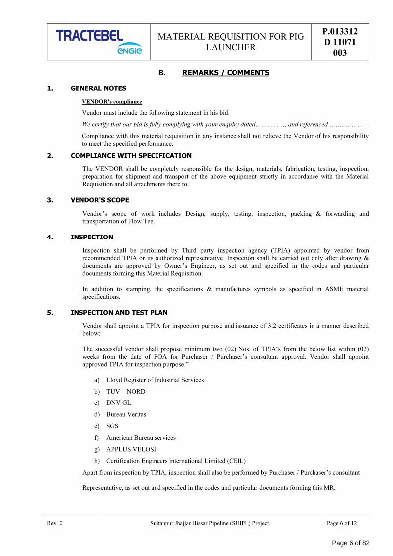
B. REMARKS / COMMENTS
1. GENERAL NOTES
VENDOR's compliance
Vendor must include the following statement in his bid:
We certify that our bid is fully complying with your enquiry dated……………, and referenced……………… .
Compliance with this material requisition in any instance shall not relieve the Vendor of his responsibility
to meet the specified performance.
2. COMPLIANCE WITH SPECIFICATION
The VENDOR shall be completely responsible for the design, materials, fabrication, testing, inspection,
preparation for shipment and transport of the above equipment strictly in accordance with the Material
Requisition and all attachments there to.
3. VENDOR'S SCOPE
Vendor’s scope of work includes Design, supply, testing, inspection, packing & forwarding and
transportation of Flow Tee.
4. INSPECTION
Inspection shall be performed by Third party inspection agency (TPIA) appointed by vendor from
recommended TPIA or its authorized representative. Inspection shall be carried out only after drawing &
documents are approved by Owner’s Engineer, as set out and specified in the codes and particular
documents forming this Material Requisition.
In addition to stamping, the specifications & manufactures symbols as specified in ASME material
specifications.
5. INSPECTION AND TEST PLAN
Vendor shall appoint a TPIA for inspection purpose and issuance of 3.2 certificates in a manner described
below:
The successful vendor shall propose minimum two (02) Nos. of TPIA‘s from the below list within (02)
weeks from the date of FOA for Purchaser / Purchaser’s consultant approval. Vendor shall appoint
approved TPIA for inspection purpose.”
a) Lloyd Register of Industrial Services
b) TUV – NORD
c) DNV GL
d) Bureau Veritas
e) SGS
f) American Bureau services
g) APPLUS VELOSI
h) Certification Engineers international Limited (CEIL)
Apart from inspection by TPIA, inspection shall also be performed by Purchaser / Purchaser’s consultant
Representative, as set out and specified in the codes and particular documents forming this MR.
Page 6 of 82
MATERIAL REQUISITION FOR PIG
LAUNCHER
P.013312
D 11071
003
Rev. 0 Sultanpur Jhajjar Hissar Pipeline (SJHPL) Project. Page 7 of 12
6. APPLICABLE DOCUMENTS
General prescriptions, requirements and information are listed in annex C of this Material Requisition.
7. VENDOR'S DOCUMENTS
Vendor shall submit the documents as listed under point D of this Material Requisition.
All documents shall be submitted in English language only.
Vendor shall ensure that following information are properly entered in each drawing/document
Tender Number
No. of Equipment /Package
Name of Project
Owner
Vendor Name
Drawing/Document Title
Drawing/Document No.
Drawing/Document Rev. No. & Date
Transmittal No. & Date.
Page 7 of 82
MATERIAL REQUISITION FOR PIG
LAUNCHER
P.013312
D 11071
003
Rev. 0 Sultanpur Jhajjar Hissar Pipeline (SJHPL) Project. Page 8 of 12
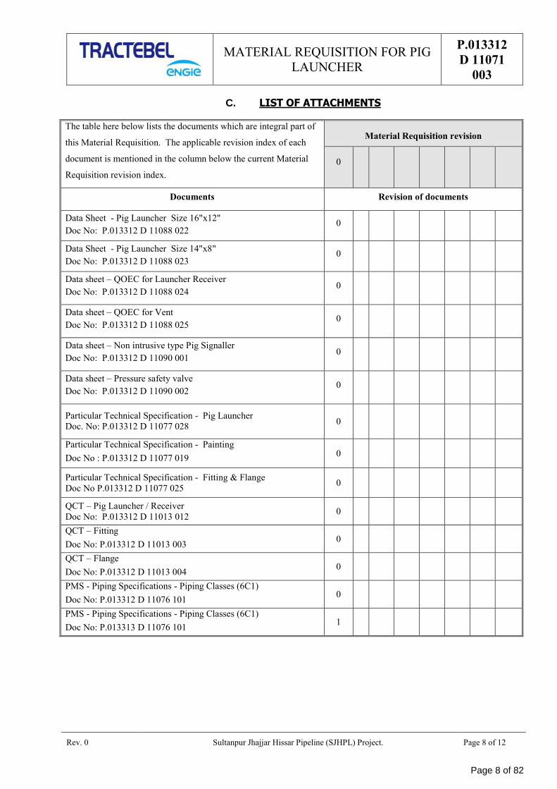
C. LIST OF ATTACHMENTS
The table here below lists the documents which are integral part of
this Material Requisition. The applicable revision index of each
document is mentioned in the column below the current Material
Requisition revision index.
Material Requisition revision
0
Documents Revision of documents
Data Sheet - Pig Launcher Size 16"x12"
Doc No: P.013312 D 11088 022 0
Data Sheet - Pig Launcher Size 14"x8"
Doc No: P.013312 D 11088 023 0
Data sheet – QOEC for Launcher Receiver
Doc No: P.013312 D 11088 024 0
Data sheet – QOEC for Vent
Doc No: P.013312 D 11088 025 0
Data sheet – Non intrusive type Pig Signaller
Doc No: P.013312 D 11090 001 0
Data sheet – Pressure safety valve
Doc No: P.013312 D 11090 002 0
Particular Technical Specification - Pig Launcher
Doc. No: P.013312 D 11077 028 0
Particular Technical Specification - Painting
Doc No : P.013312 D 11077 019 0
Particular Technical Specification - Fitting & Flange
Doc No P.013312 D 11077 025 0
QCT – Pig Launcher / Receiver
Doc No: P.013312 D 11013 012 0
QCT – Fitting
Doc No: P.013312 D 11013 003 0
QCT – Flange
Doc No: P.013312 D 11013 004 0
PMS - Piping Specifications - Piping Classes (6C1)
Doc No: P.013312 D 11076 101 0
PMS - Piping Specifications - Piping Classes (6C1)
Doc No: P.013313 D 11076 101 1
Page 8 of 82
MATERIAL REQUISITION FOR PIG
LAUNCHER
P.013312
D 11071
003
Rev. 0 Sultanpur Jhajjar Hissar Pipeline (SJHPL) Project. Page 9 of 12
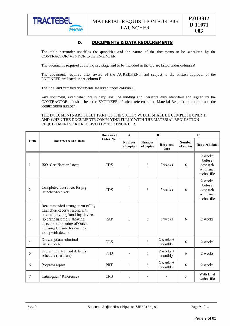
D. DOCUMENTS & DATA REQUIREMENTS
The table hereunder specifies the quantities and the nature of the documents to be submitted by the
CONTRACTOR/ VENDOR to the ENGINEER.
The documents required at the inquiry stage and to be included in the bid are listed under column A.
The documents required after award of the AGREEMENT and subject to the written approval of the
ENGINEER are listed under column B.
The final and certified documents are listed under column C.
Any document, even when preliminary, shall be binding and therefore duly identified and signed by the
CONTRACTOR. It shall bear the ENGINEER's Project reference, the Material Requisition number and the
identification number.
THE DOCUMENTS ARE FULLY PART OF THE SUPPLY WHICH SHALL BE COMPLETE ONLY IF
AND WHEN THE DOCUMENTS COMPLYING FULLY WITH THE MATERIAL REQUISITION
REQUIREMENTS ARE RECEIVED BY THE ENGINEER.
Item Documents and Data
Document
Index No.
A B C
Number
of copies
Number
of copies Required
date
Number
of copies Required date
1 ISO Certification latest CDS 1 6 2 weeks 6
2 weeks
before
despatch
with final
techn. file
2 Completed data sheet for pig
launcher/receiver CDS 1 6 2 weeks 6
2 weeks
before
despatch
with final
techn. file
3
Recommended arrangement of Pig
Launcher/Receiver along with
internal tray, pig handling device,
jib crane assembly showing
direction of opening of Quick
Opening Closure for each plot
along with details
RAP 1 6 2 weeks 6 2 weeks
4 Drawing/data submittal
list/schedule DLS - 6
2 weeks +
monthly 6 2 weeks
5 Fabrication, test and delivery
schedule (per item) FTD - 6
2 weeks +
monthly 6 2 weeks
6 Progress report PRT - 6 2 weeks +
monthly 6 2 weeks
7 Catalogues / References CRS 1 - - 3 With final
techn. file
Page 9 of 82
MATERIAL REQUISITION FOR PIG
LAUNCHER
P.013312
D 11071
003
Rev. 0 Sultanpur Jhajjar Hissar Pipeline (SJHPL) Project. Page 10 of 12
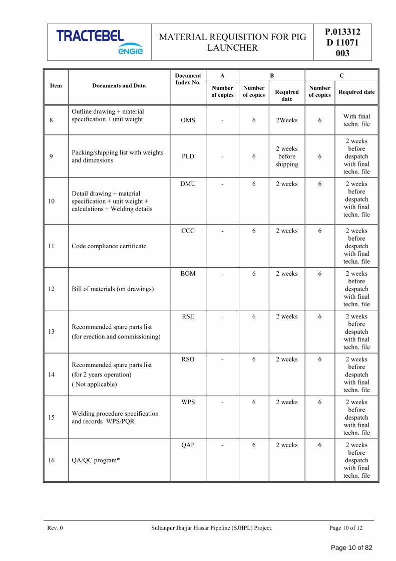
Item Documents and Data
Document
Index No.
A B C
Number
of copies
Number
of copies Required
date
Number
of copies Required date
8
Outline drawing + material
specification + unit weight
OMS - 6 2Weeks 6 With final
techn. file
9 Packing/shipping list with weights
and dimensions PLD - 6
2 weeks
before
shipping
6
2 weeks
before
despatch
with final
techn. file
10
Detail drawing + material
specification + unit weight +
calculations + Welding details
DMU - 6 2 weeks 6 2 weeks
before
despatch
with final
techn. file
11 Code compliance certificate
CCC - 6 2 weeks 6 2 weeks
before
despatch
with final
techn. file
12 Bill of materials (on drawings)
BOM - 6 2 weeks 6 2 weeks
before
despatch
with final
techn. file
13 Recommended spare parts list
(for erection and commissioning)
RSE - 6 2 weeks 6 2 weeks
before
despatch
with final
techn. file
14
Recommended spare parts list
(for 2 years operation)
( Not applicable)
RSO - 6 2 weeks 6 2 weeks
before
despatch
with final
techn. file
15 Welding procedure specification
and records WPS/PQR
WPS - 6 2 weeks 6 2 weeks
before
despatch
with final
techn. file
16 QA/QC program*
QAP - 6 2 weeks 6 2 weeks
before
despatch
with final
techn. file
Page 10 of 82
MATERIAL REQUISITION FOR PIG
LAUNCHER
P.013312
D 11071
003
Rev. 0 Sultanpur Jhajjar Hissar Pipeline (SJHPL) Project. Page 11 of 12
Item Documents and Data
Document
Index No.
A B C
Number
of copies
Number
of copies Required
date
Number
of copies Required date
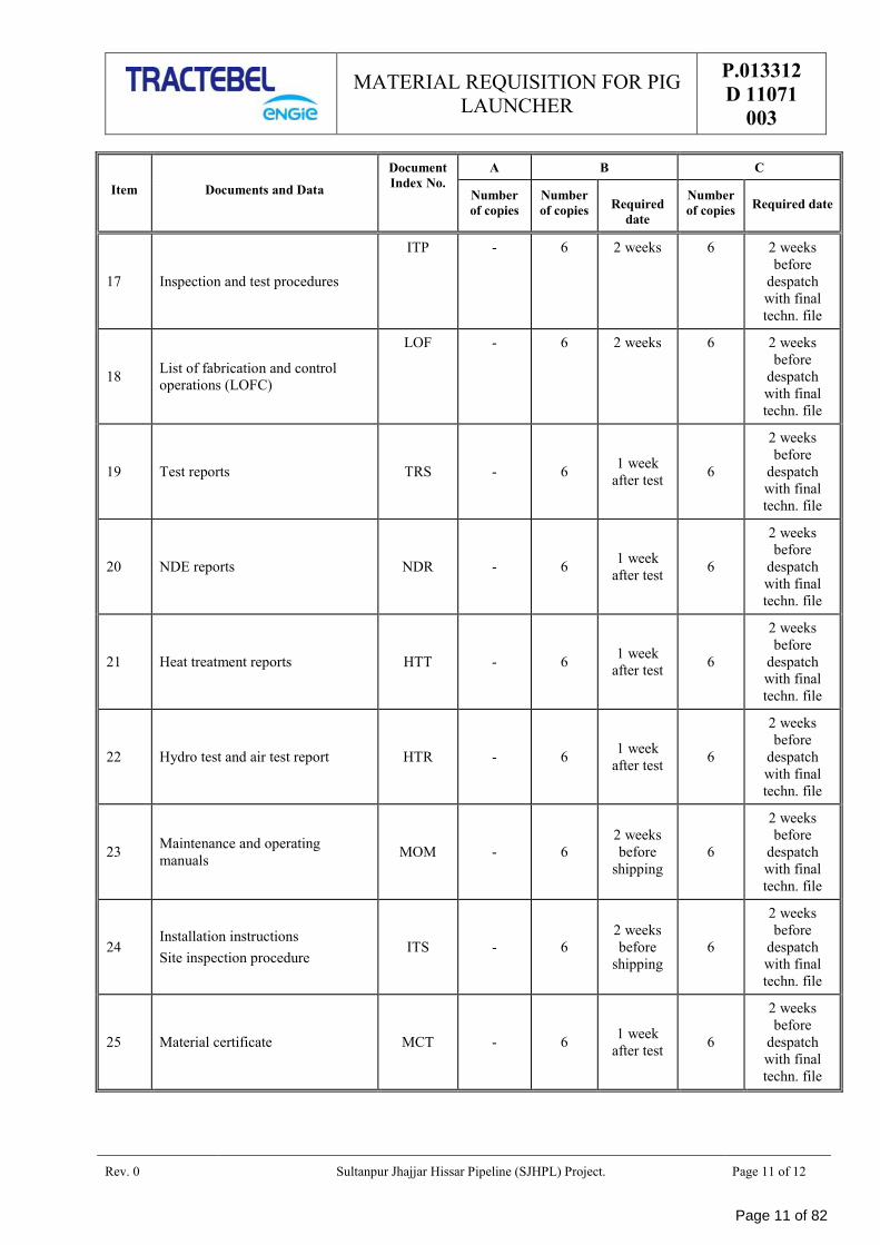
17 Inspection and test procedures
ITP - 6 2 weeks 6 2 weeks
before
despatch
with final
techn. file
18 List of fabrication and control
operations (LOFC)
LOF - 6 2 weeks 6 2 weeks
before
despatch
with final
techn. file
19 Test reports TRS - 6 1 week
after test 6
2 weeks
before
despatch
with final
techn. file
20 NDE reports NDR - 6 1 week
after test 6
2 weeks
before
despatch
with final
techn. file
21 Heat treatment reports HTT - 6 1 week
after test 6
2 weeks
before
despatch
with final
techn. file
22 Hydro test and air test report HTR - 6 1 week
after test 6
2 weeks
before
despatch
with final
techn. file
23 Maintenance and operating
manuals MOM - 6
2 weeks
before
shipping
6
2 weeks
before
despatch
with final
techn. file
24 Installation instructions
Site inspection procedure ITS - 6
2 weeks
before
shipping
6
2 weeks
before
despatch
with final
techn. file
25 Material certificate MCT - 6 1 week
after test 6
2 weeks
before
despatch
with final
techn. file
Page 11 of 82
MATERIAL REQUISITION FOR PIG
LAUNCHER
P.013312
D 11071
003
Rev. 0 Sultanpur Jhajjar Hissar Pipeline (SJHPL) Project. Page 12 of 12
Item Documents and Data
Document
Index No.
A B C
Number
of copies
Number
of copies Required
date
Number
of copies Required date
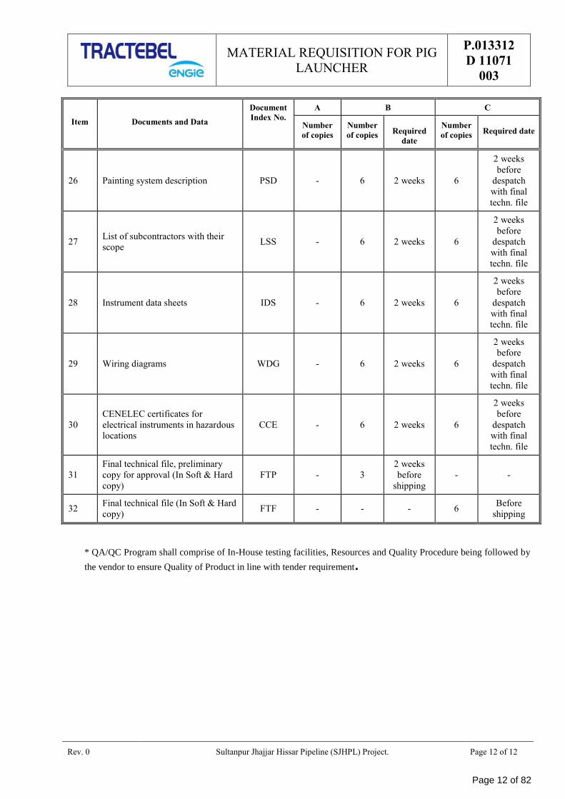
26 Painting system description PSD - 6 2 weeks 6
2 weeks
before
despatch
with final
techn. file
27 List of subcontractors with their
scope LSS - 6 2 weeks 6
2 weeks
before
despatch
with final
techn. file
28 Instrument data sheets IDS - 6 2 weeks 6
2 weeks
before
despatch
with final
techn. file
29 Wiring diagrams WDG - 6 2 weeks 6
2 weeks
before
despatch
with final
techn. file
30
CENELEC certificates for
electrical instruments in hazardous
locations
CCE - 6 2 weeks 6
2 weeks
before
despatch
with final
techn. file
31
Final technical file, preliminary
copy for approval (In Soft & Hard
copy)
FTP - 3
2 weeks
before
shipping
- -
32 Final technical file (In Soft & Hard
copy) FTF - - - 6
Before
shipping
* QA/QC Program shall comprise of In-House testing facilities, Resources and Quality Procedure being followed by
the vendor to ensure Quality of Product in line with tender requirement.
Page 12 of 82
DATA SHEET NO.
P.013312 D 11088 022
Page 1 of 2
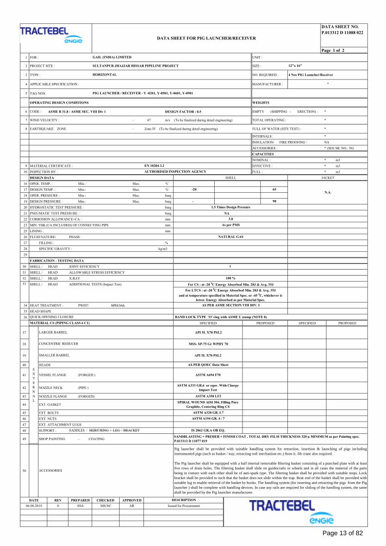
1 FOR : UNIT :
2 PROJECT SITE : SIZE :
3 TYPE : NO. REQUIRED :
4 APPLICABLE SPECIFICATION : MANUFACTURER :
5 TAG NOS.
OPERATING DESIGN CONDITIONS WEIGHTS
6 CODE : ASME B 31.8 / ASME SEC. VIII Div 1 DESIGN FACTOR : 0.5 EMPTY (SHIPPING - ERECTION) : *
7 WIND VELOCITY : - 47 m/s (To be finalized during detail engineering) TOTAL OPERATING : *
8 EARTHQUAKE ZONE - Zone IV (To be finalized during detail engineering) FULL OF WATER (SITE TEST) : *
INTERNALS : *
INSULATION/ FIRE PROOFING : NA
ACCESSORIES : * (SEE SR. NO.: 50)
CAPACITIES
NOMINAL : * m3
9 MATERIAL CERTIFICATE : EFFECTIVE : * m3
10 INSPECTION BY : FULL : * m3
DESIGN DATA SHELL JACKET
16 OPER. TEMP. : Min.- Max. °C
17 DESIGN TEMP. : Min.- Max. °C
18 OPER. PRESSURE : Min.- Max. barg
19 DESIGN PRESSURE : Min.- Max. barg -
20 HYDROSTATIC TEST PRESSURE : barg
21 PNEUMATIC TEST PRESSURE : barg NA
22 CORROSION ALLOWANCE=CA : mm
23 MIN. THK (CA INCLUDED) OF CONNECTING PIPE mm
25 LINING : mm
26 FLUID NATURE/ PHASE
27 FILLING : %
28 SPECIFIC GRAVITY : kg/m3
29
FABRICATION - TESTING DATA
30 SHELL / HEAD JOINT EFFICIENCY
31 SHELL / HEAD ALLOWABLE STRESS EFFICIENCY
32 SHELL / HEAD X-RAY
SHELL / HEAD ADDITIONAL TESTS (Impact Test)
34 HEAT TREATMENT : PWHT/ SPECIAL
35 HEAD SHAPE
36
SPECIFIED PROPOSED SPECIFIED PROPOSED
37
38
39
40 HEADS
41 VESSEL FLANGE (FORGED )
42 NOZZLE NECK (PIPE )
43 NOZZLE FLANGE (FORGED)
44 EXT. GASKET
45 EXT. BOLTS
46 EXT. NUTS
47 EXT. ATTACHMENT LUGS
48 SUPPORT :
49 SHOP PAINTING - COATING
50
DATE REV PREPARED CHECKED APPROVED
33
E
X
T
E
R
N
A
L
DESCRIPTION
0
As per PMS
NATURAL GAS
3.0
100 %
SPIRAL WOUND AISI 304, Filling Pure
Graphite, Centering Ring CS
Issued for Procurement
*
For LTCS : at -20 0C Energy Absorbed Min. 28J & Avg. 35J
and at temperature specified in Material Spec. or -45 0C, whichever is
lower. Energy Absorbed as per Material Spec.
-20
EN 10204 3.2
4 Nos PIG Launcher/Receiver
65
AR
98
1.5 Times Design Pressure
ASTM A320 GR. L7
SADDLES / SKIRT/RING / LEG / BRACKET
ASTM A194 GR. 4 / 7
QUICK OPENING CLOSURE
AS PER QOEC Data Sheet
ASTM A350 LF2
ASTM A694 F70
AUTHORISED INSPECTION AGENCY
AS PER ASME SECTION VIII DIV. I
API 5L X70 PSL2
LARGER BARREL
MATERIAL CS (PIPING CLASS 6 C1)
SMALLER BARREL
ACCESSORIES
BAND LOCK TYPE 'O' ring with ASME U stamp (NOTE 8)
API 5L X70 PSL2
CONCENTRIC REDUCER
06.08.2019
N.A.
1
Pig launcher shall be provided with suitable handling system for retraction, insertion & launching of pigs including
instrumented pigs (such as basket / tray; retracting rod/ mechanism etc.) from it. Jib crane also required.
The Pig launcher shall be equipped with a half internal removable filtering basket consisting of a punched plate with at least
five rows of drain holes. The filtering basket shall slide on guides/rails or wheels and in all cases the material of the parts
being in contact with each other shall be of anti-spark type. The filtering basket shall be provided with suitable stops. Lock
bracket shall be provided to such that the basket does not slide within the trap. Rear end of the basket shall be provided with
suitable lug to enable retrieval of the basket by hooks. The handling system (for inserting and retracting the pigs from the Pig
launcher ) shall be complete with handling devices. In case any rails are required for sliding of the handling system, the same
shall be provided by the Pig launcher manufacturer.
IS 2062 GR.A OR EQ.
ASTM A333 GR.6 or equv. With Charpy
Impact Test
For CS : at -20 0C Energy Absorbed Min. 28J & Avg. 35J
MSS- SP-75 Gr WPHY 70
SSA
GAIL (INDIA) LIMITED
SULTANPUR JHAJJAR HISSAR PIPELINE PROJECT
HORIZONTAL
PIG LAUNCHER / RECEIVER - Y -0201, Y-0501, Y-0601, Y-0901
MS/NC
SANDBLASTING + PRIMER + FINISH COAT , TOTAL DRY FILM THICKNESS 320 µ MINIMUM as per Painting spec.
P.013312 D 11077 019
DATA SHEET FOR PIG LAUNCHER/RECEIVER
12"x 16"
Page 13 of 82
DATA SHEET No
P.013312 D 11088 022
Page 2 of 2
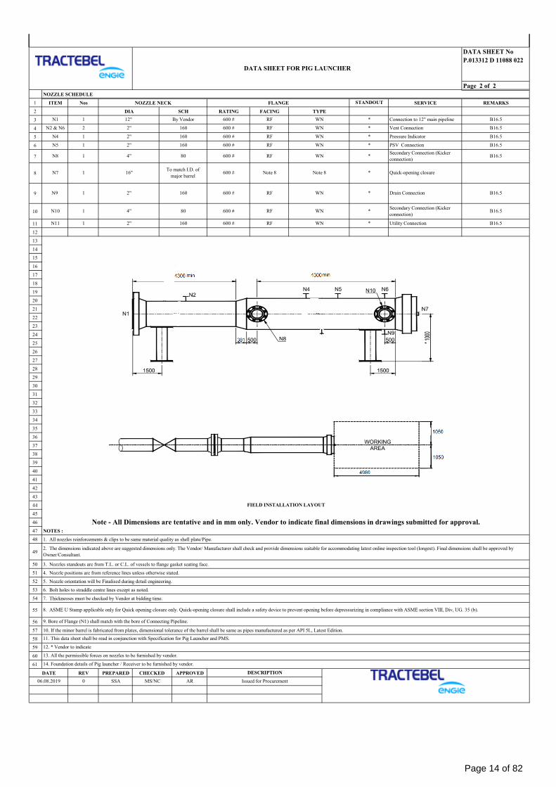
NOZZLE SCHEDULE
1 ITEM Nos NOZZLE NECK FLANGE SERVICE REMARKS
2 DIA SCH RATING FACING TYPE
3
4
5
6
7
8
9
10
11
12
13
14
15
16
17
18
19
20
21
22
23
24
25
26
27
28
29
30
31
32
33
34
35
36
37
38
39
40
41
42
43
44
45
46
47 NOTES :
48 1. All nozzles reinforcements & clips to be same material quality as shell plate/Pipe.
49
50 3. Nozzles standouts are from T.L. or C.L. of vessels to flange gasket seating face.
51 4. Nozzle positions are from reference lines unless otherwise stated.
52 5. Nozzle orientation will be Finalised during detail engineering.
53 6. Bolt holes to straddle centre lines except as noted.
54 7. Thicknesses must be checked by Vendor at bidding time.
55
56
57 10. If the minor barrel is fabricated from plates, dimensional tolerance of the barrel shall be same as pipes manufactured as per API 5L, Latest Edition.
58
59
60
61
DATE REV PREPARED CHECKED APPROVED
2. The dimensions indicated above are suggested dimensions only. The Vendor/ Manufacturer shall check and provide dimensions suitable for accommodating latest online inspection tool (longest). Final dimensions shall be approved by
Owner/Consultant.
8. ASME U Stamp applicable only for Quick opening closure only. Quick-opening closure shall include a safety device to prevent opening before depressurizing in compliance with ASME section VIII, Div, UG. 35 (b).
WN * Utility Connection B16.5
STANDOUT
N10 1 *
N11 1 2" 160 600 #
12"
B16.5
1 2" 160
1601 2"
Secondary Connection (Kicker
connection)
*
Note 8
WN
WN
Note 8
Pressure Indicator
B16.5WN
*
PSV ConnectionN5
By Vendor RF
N2 & N6 2 2"
600 #N1
600 #
RF
RF
RF
16"
160 600 #
To match I.D. of
major barrel
4"
600 #
N8
N4
1
2"
FIELD INSTALLATION LAYOUT
B16.5
Drain Connection
*
RF WN
DESCRIPTION
9. Bore of Flange (N1) shall match with the bore of Connecting Pipeline.
N7 1
4"
600 #
Note - All Dimensions are tentative and in mm only. Vendor to indicate final dimensions in drawings submitted for approval.
600 #
WN
AR Issued for Procurement
Secondary Connection (Kicker
connection)
Quick-opening closure
RF
600 #
B16.5
RF
WN *
B16.5
*
*
*
B16.5
SSA
Connection to 12" main pipeline
N9
80 WN
B16.5
Vent Connection
1
11. This data sheet shall be read in conjunction with Specification for Pig Launcher and PMS.
12. * Vendor to indicate
13. All the permissible forces on nozzles to be furnished by vendor.
14. Foundation details of Pig launcher / Receiver to be furnished by vendor.
06.08.2019 MS/NC
80
DATA SHEET FOR PIG LAUNCHER
0
160
600 #
1 RF
Page 14 of 82
DATA SHEET NO.
P.013312 D 11088 023
Page 1 of 2
1 FOR : UNIT :
2 PROJECT SITE : SIZE :
3 TYPE : NO. REQUIRED :
4 APPLICABLE SPECIFICATION : MANUFACTURER :
5 TAG NOS.
OPERATING DESIGN CONDITIONS WEIGHTS
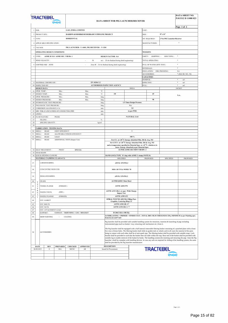
6 CODE : ASME B 31.8 / ASME SEC. VIII Div 1 DESIGN FACTOR : 0.4 EMPTY (SHIPPING - ERECTION) : *
7 WIND VELOCITY : - 50 m/s (To be finalized during detail engineering) TOTAL OPERATING : *
8 EARTHQUAKE ZONE - Zone III (To be finalized during detail engineering) FULL OF WATER (SITE TEST) : *
INTERNALS : *
INSULATION/ FIRE PROOFING : NA
ACCESSORIES : * (SEE SR. NO.: 50)
CAPACITIES
NOMINAL : * m3
9 MATERIAL CERTIFICATE : EFFECTIVE : * m3
10 INSPECTION BY : FULL : * m3
DESIGN DATA SHELL JACKET
16 OPER. TEMP. : Min.- Max. °C
17 DESIGN TEMP. : Min.- Max. °C
18 OPER. PRESSURE : Min.- Max. barg
19 DESIGN PRESSURE : Min.- Max. barg -
20 HYDROSTATIC TEST PRESSURE : barg
21 PNEUMATIC TEST PRESSURE : barg NA
22 CORROSION ALLOWANCE=CA : mm
23 MIN. THK (CA INCLUDED) OF CONNECTING PIPE mm
25 LINING : mm
26 FLUID NATURE/ PHASE
27 FILLING : %
28 SPECIFIC GRAVITY : kg/m3
29
FABRICATION - TESTING DATA
30 SHELL / HEAD JOINT EFFICIENCY
31 SHELL / HEAD ALLOWABLE STRESS EFFICIENCY
32 SHELL / HEAD X-RAY
SHELL / HEAD ADDITIONAL TESTS (Impact Test)
34 HEAT TREATMENT : PWHT/ SPECIAL
35 HEAD SHAPE
36
SPECIFIED PROPOSED SPECIFIED PROPOSED
37
38
39
40 HEADS
41 VESSEL FLANGE (FORGED )
42 NOZZLE NECK (PIPE )
43 NOZZLE FLANGE (FORGED)
44 EXT. GASKET
45 EXT. BOLTS
46 EXT. NUTS
47 EXT. ATTACHMENT LUGS
48 SUPPORT :
49 SHOP PAINTING - COATING
50
DATE REV PREPARED CHECKED APPROVED
33
E
X
T
E
R
N
A
L
DESCRIPTION
EN 10204 3.2
SPIRAL WOUND AISI 304, Filling Pure
Graphite, Centering Ring CS
Issued for Procurement0
As per PMS
NATURAL GAS
SANDBLASTING + PRIMER + FINISH COAT , TOTAL DRY FILM THICKNESS 320 µ MINIMUM as per Painting spec.
P.013312 D 11077 019
*
For LTCS : at -20 0C Energy Absorbed Min. 28J & Avg. 35J
and at temperature specified in Material Spec. or -45 0C, whichever is
lower. Energy Absorbed as per Material Spec.
-20
ASTM A194 GR. 4 / 7
3.0
2 Nos PIG Launcher/Receiver
65
AR
98
1.5 Times Design Pressure
ASTM A320 GR. L7
SADDLES / SKIRT/RING / LEG / BRACKET
MATERIAL CS (PIPING CLASS 6 C1)
AS PER QOEC Data Sheet
IS 2062 GR.A OR EQ.
ASTM A333 GR.6 or equv. With Charpy
Impact Test
ASTM A350 LF2
QUICK OPENING CLOSURE
06.08.2019
For CS : at -20 0C Energy Absorbed Min. 28J & Avg. 35J
MSS- SP-75 Gr WPHY 70
AUTHORISED INSPECTION AGENCY
AS PER ASME SECTION VIII DIV. I
API 5L X70 PSL2
LARGER BARREL
1
100 %
BAND LOCK TYPE 'O' ring with ASME U stamp (NOTE 8)
API 5L X70 PSL2
ASTM A694 F70
SMALLER BARREL
Pig launcher shall be provided with suitable handling system for retraction, insertion & launching of pigs including
instrumented pigs (such as basket / tray; retracting rod/ mechanism etc.) from it.
The Pig launcher shall be equipped with a half internal removable filtering basket consisting of a punched plate with at least
five rows of drain holes. The filtering basket shall slide on guides/rails or wheels and in all cases the material of the parts
being in contact with each other shall be of anti-spark type. The filtering basket shall be provided with suitable stops. Lock
bracket shall be provided to such that the basket does not slide within the trap. Rear end of the basket shall be provided with
suitable lug to enable retrieval of the basket by hooks. The handling system (for inserting and retracting the pigs from the Pig
launcher ) shall be complete with handling devices. In case any rails are required for sliding of the handling system, the same
shall be provided by the Pig launcher manufacturer.
ACCESSORIES
CONCENTRIC REDUCER
SSA MS/NC
GAIL (INDIA) LIMITED
HARIDWAR RISHIKESH DEHRADUN PIPELINE PROJECT
HORIZONTAL
PIG LAUNCHER - Y -0401, PIG RECEIVER - Y-1201
N.A.
DATA SHEET FOR PIG LAUNCHER/RECEIVER
8"x 14"
Page 1 of 1
Page 15 of 82
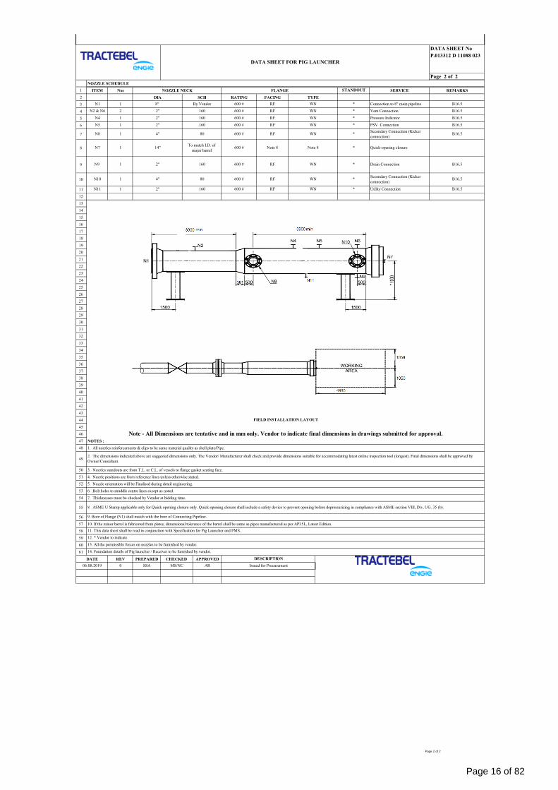
DATA SHEET No
P.013312 D 11088 023
Page 2 of 2
NOZZLE SCHEDULE
1 ITEM Nos NOZZLE NECK FLANGE SERVICE REMARKS
2 DIA SCH RATING FACING TYPE
3
4
5
6
7
8
9
10
11
12
13
14
15
16
17
18
19
20
21
22
23
24
25
26
27
28
29
30
31
32
33
34
35
36
37
38
39
40
41
42
43
44
45
46
47 NOTES :
48 1. All nozzles reinforcements & clips to be same material quality as shell plate/Pipe.
49
50 3. Nozzles standouts are from T.L. or C.L. of vessels to flange gasket seating face.
51 4. Nozzle positions are from reference lines unless otherwise stated.
52 5. Nozzle orientation will be Finalised during detail engineering.
53 6. Bolt holes to straddle centre lines except as noted.
54 7. Thicknesses must be checked by Vendor at bidding time.
55
56
57 10. If the minor barrel is fabricated from plates, dimensional tolerance of the barrel shall be same as pipes manufactured as per API 5L, Latest Edition.
58
59
60
61
DATE REV PREPARED CHECKED APPROVED
2. The dimensions indicated above are suggested dimensions only. The Vendor/ Manufacturer shall check and provide dimensions suitable for accommodating latest online inspection tool (longest). Final dimensions shall be approved by
Owner/Consultant.
8. ASME U Stamp applicable only for Quick opening closure only. Quick-opening closure shall include a safety device to prevent opening before depressurizing in compliance with ASME section VIII, Div, UG. 35 (b).
WN * Utility Connection B16.5N11 1 2" 160
*
600 #
STANDOUT
N10 1
8"
B16.5Secondary Connection (Kicker
connection)
600 #1 2" 160
*1 2" 160 600 #N5
By Vendor RF
N2 & N6 2 2"
600 #N1
600 #
RF
Note 814"
160 600 #
N8
N4
1
2"
DESCRIPTION
9. Bore of Flange (N1) shall match with the bore of Connecting Pipeline.
N7 1
06.08.2019
4"
MS/NC
600 #
Note - All Dimensions are tentative and in mm only. Vendor to indicate final dimensions in drawings submitted for approval.
FIELD INSTALLATION LAYOUT
B16.5
Drain Connection
*To match I.D. of
major barrelNote 8
4"
Issued for Procurement
Secondary Connection (Kicker
connection)
Quick-opening closure
RF
*
600 # RF
*
RF
WN
B16.5WN
WN
WN
B16.5
*
*
RF
Vent Connection
PSV Connection
Pressure Indicator
WN B16.5
B16.5
RF
WN *N9
80 WN
SSA
Connection to 8" main pipeline1
0
160
600 #
AR
13. All the permissible forces on nozzles to be furnished by vendor.
14. Foundation details of Pig launcher / Receiver to be furnished by vendor.
B16.5
12. * Vendor to indicate
80
DATA SHEET FOR PIG LAUNCHER
1 RF
11. This data sheet shall be read in conjunction with Specification for Pig Launcher and PMS.
Page 2 of 2
Page 16 of 82
QUICK OPENING END
CLOSURE
P.013312
D 11088
024
SULTANPUR JHAJJAR HISSAR PIPELINE (SJHPL) PROJECT
TRACTEBEL ENGINEERING PVT. LTD.
DATA SHEET QUICK OPENING END CLOSURE (QOEC)
RERT
0 30.07.2019 Issued for Procurement SSA MS/NC AR
Rev. Date Description Prepared By Checked By Approved By
Page 1 of 3
Page 17 of 82
QUICK OPENING END
CLOSURE
P.013312
D 11088
024
Rev. 0 Sultanpur Jhajjar Hissar Pipeline Project
Page 2 of 3
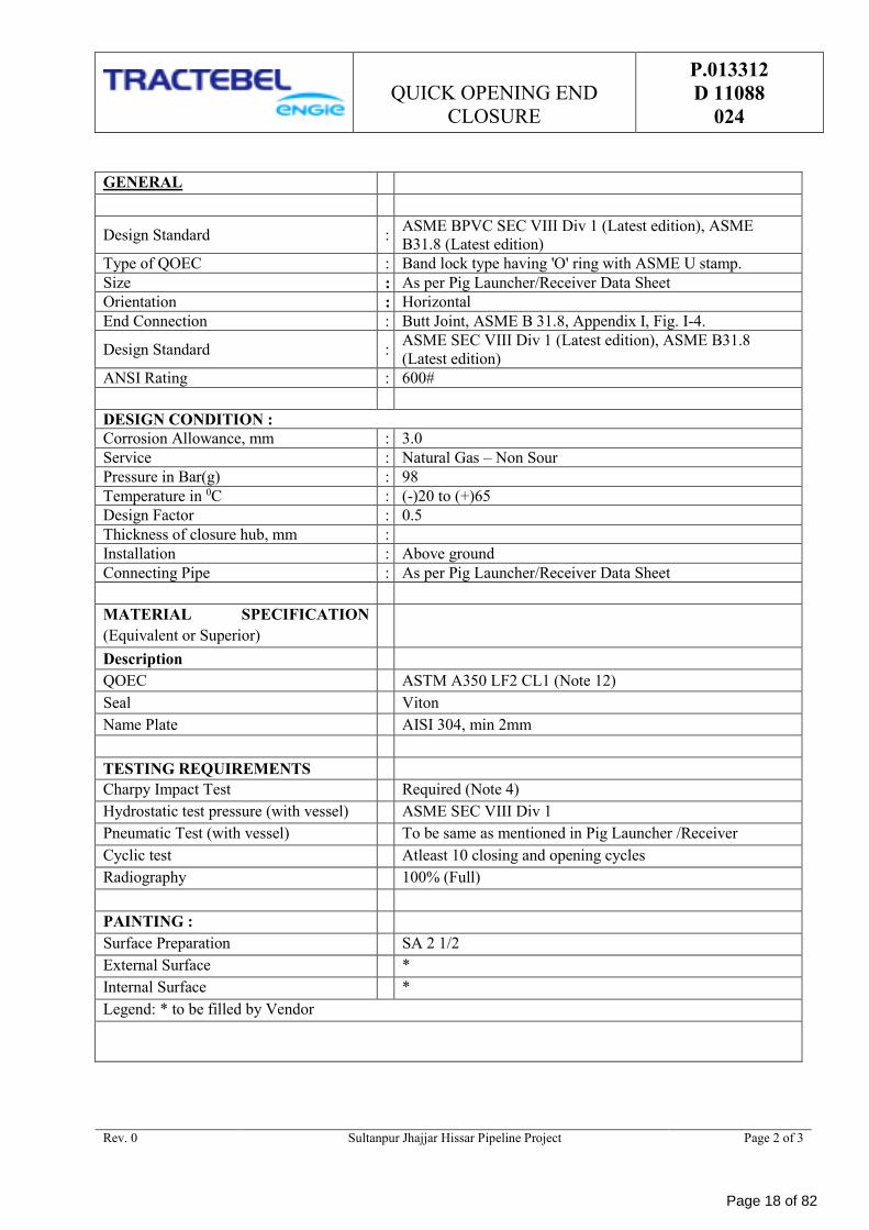
GENERAL
Design Standard : ASME BPVC SEC VIII Div 1 (Latest edition), ASME
B31.8 (Latest edition)
Type of QOEC : Band lock type having 'O' ring with ASME U stamp.
Size : As per Pig Launcher/Receiver Data Sheet
Orientation : Horizontal
End Connection : Butt Joint, ASME B 31.8, Appendix I, Fig. I-4.
Design Standard : ASME SEC VIII Div 1 (Latest edition), ASME B31.8
(Latest edition)
ANSI Rating : 600#
DESIGN CONDITION :
Corrosion Allowance, mm : 3.0
Service : Natural Gas – Non Sour
Pressure in Bar(g) : 98
Temperature in 0C : (-)20 to (+)65
Design Factor : 0.5
Thickness of closure hub, mm :
Installation : Above ground
Connecting Pipe : As per Pig Launcher/Receiver Data Sheet
MATERIAL SPECIFICATION
(Equivalent or Superior)
Description
QOEC ASTM A350 LF2 CL1 (Note 12)
Seal Viton
Name Plate AISI 304, min 2mm
TESTING REQUIREMENTS
Charpy Impact Test Required (Note 4)
Hydrostatic test pressure (with vessel) ASME SEC VIII Div 1
Pneumatic Test (with vessel) To be same as mentioned in Pig Launcher /Receiver
Cyclic test Atleast 10 closing and opening cycles
Radiography 100% (Full)
PAINTING :
Surface Preparation SA 2 1/2
External Surface *
Internal Surface *
Legend: * to be filled by Vendor
Page 18 of 82
QUICK OPENING END
CLOSURE
P.013312
D 11088
024
Rev. 0 Sultanpur Jhajjar Hissar Pipeline Project
Page 3 of 3
Notes:
1. This data sheet shall be read in conjunction with Specification, Data Sheet for Pig Launcher and
PMS.
2. Quick opening closures shall be equipped with safety locking devices in compliance with Section
VIII, Division I, UG-35.2 of the BPV Code.
3. For the welding end, the out of roundness (i.e. difference between maximum and minimum ID at
pipe end) tolerance shall be OD > 6” - 3 mm (max.)
4. The Charpy V-notch test shall be conducted at -20°C. Test procedure shall conform to ASTM A
370. The average absorbed energy value of three full sized specimens shall be 35 J. The minimum
impact energy value of any of the specimen analyzed as above shall not be less than 28 J. If LTCS
material used for construction, Impact test shall be carried out as per material Standard impact test
requirements temperature or (-) 450C whichever is lower.
5. Lifting Eye shall be provided for hinged closure.
6. Correct operation of QOEC & system shall be established and furnished to purchaser for as built
condition of piping system.
7. All Inspection and tests shall be carried out as per approved QAP. Unless otherwise specified, all
tests shall be witnessed by the purchase / control authority.
8. Material compliance as per EN 10204 3.2 certification.
9. The painting shall be carried out as per Painting specification no. P.013312 D 11077 019
10. Minimum Marking: Manufacturer Name, Nominal Diameter, Heat number, Tag number, Material,
Design Pressure, and Hydro test Pressure, Year of Manufacturing.
11. Quick Opening Closure shall be ASME "U" stamped.
12. Actual yield strength for ASTM A350 LF2 Cl.1 shall be minimum 47000 PSI (ie, Two Third Yield
strength of connecting pipe).
Page 19 of 82
QUICK OPENING END
CLOSURE FOR VENT
P.013312
D 11088
025
SULTANPUR JHAJJAR HISSAR PIPELINE (SJHPL) PROJECT
TRACTEBEL ENGINEERING PVT. LTD.
DATA SHEET QUICK OPENING END CLOSURE (QOEC) FOR VENT LINE
0 01.08.2019 Issued for Procurement SSA MS/NC AR
Rev. Date Description Prepared By Checked By Approved By
Page 1 of 3
Page 20 of 82
QUICK OPENING END
CLOSURE FOR VENT
P.013312
D 11088
025
Rev. 0 Sultanpur Jhajjar Hissar Pipeline Project
Page 2 of 3
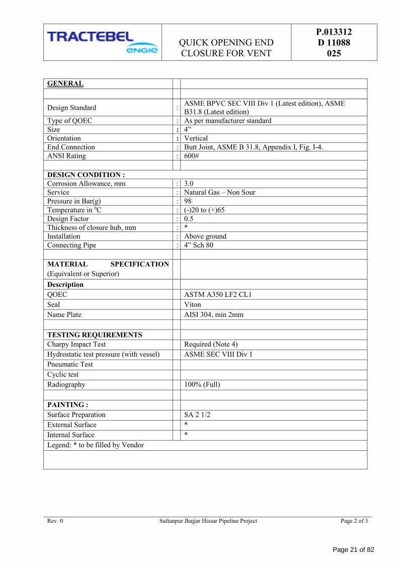
GENERAL
Design Standard : ASME BPVC SEC VIII Div 1 (Latest edition), ASME
B31.8 (Latest edition)
Type of QOEC : As per manufacturer standard
Size : 4”
Orientation : Vertical
End Connection : Butt Joint, ASME B 31.8, Appendix I, Fig. I-4.
ANSI Rating : 600#
DESIGN CONDITION :
Corrosion Allowance, mm : 3.0
Service : Natural Gas – Non Sour
Pressure in Bar(g) : 98
Temperature in 0C : (-)20 to (+)65
Design Factor : 0.5
Thickness of closure hub, mm : *
Installation : Above ground
Connecting Pipe : 4” Sch 80
MATERIAL SPECIFICATION
(Equivalent or Superior)
Description
QOEC ASTM A350 LF2 CL1
Seal Viton
Name Plate AISI 304, min 2mm
TESTING REQUIREMENTS
Charpy Impact Test Required (Note 4)
Hydrostatic test pressure (with vessel) ASME SEC VIII Div 1
Pneumatic Test
Cyclic test
Radiography 100% (Full)
PAINTING :
Surface Preparation SA 2 1/2
External Surface *
Internal Surface *
Legend: * to be filled by Vendor
Page 21 of 82
QUICK OPENING END
CLOSURE FOR VENT
P.013312
D 11088
025
Rev. 0 Sultanpur Jhajjar Hissar Pipeline Project
Page 3 of 3
Notes:
1. For the welding end, the out of roundness (i.e. difference between maximum and minimum ID at
pipe end) tolerance shall be OD > 6” - 3 mm (max.)
2. The Charpy V-notch test shall be conducted at -20°C. Test procedure shall conform to ASTM A
370. The average absorbed energy value of three full sized specimens shall be 35 J. The minimum
impact energy value of any of the specimen analyzed as above shall not be less than 28 J. If LTCS
material used for construction, Impact test shall be carried out as per material Standard impact test
requirements temperature or (-) 450C whichever is lower.
3. Correct operation of QOEC & system shall be established and furnished to purchaser for as built
condition of piping system.
4. All Inspection and tests shall be carried out as per approved QAP. Unless otherwise specified, all
tests shall be witnessed by the purchase / control authority.
5. Material compliance as per EN 10204 3.2 certification.
6. The painting shall be carried out as per Painting specification no. P.013312 D 11077 019
7. Minimum Marking: Manufacturer Name, Nominal Diameter, Heat number, Tag number, Material,
Design Pressure, and Hydro test Pressure, Year of Manufacturing.
8. Bidder shall submit catalogue of their proposed model and its functionality with bid offers.
Page 22 of 82
:
:
:
:
:
:
:
:
:
:
:
:
:
:
:
:
:
:
:
:
:
:
:
:
:
:
CLIENT: GAIL (India) Limited
PROJECT:Sultanpur Jhajjar
Hissar Pipeline Project
VENDOR: 0 31.07.2019 MA SHD AR
REV DATE PREP CHKD APPD
P.013312 D 11090 001
Sheet 1 of 2
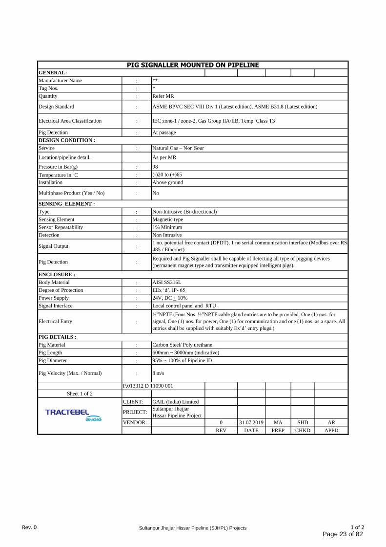
Quantity Refer MR
Pressure in Bar(g) 98
Design Standard ASME BPVC SEC VIII Div 1 (Latest edition), ASME B31.8 (Latest edition)
Electrical Area Classification IEC zone-1 / zone-2, Gas Group IIA/IIB, Temp. Class T3
Pig Detection At passage
Service Natural Gas – Non Sour
PIG SIGNALLER MOUNTED ON PIPELINEGENERAL:
Manufacturer Name **
Tag Nos. *
Location/pipeline detail. As per MR
DESIGN CONDITION :
Sensor Repeatability 1% Minimum
Temperature in 0C (-)20 to (+)65
Installation Above ground
Multiphase Product (Yes / No) No
Type Non-Intrusive (Bi-directional)
Sensing Element Magnetic type
SENSING ELEMENT :
Degree of Protection EEx ‘d’, IP- 65
Detection Non Intrusive
Signal Output1 no. potential free contact (DPDT), 1 no serial communication interface (Modbus over RS-
485 / Ethernet)
Pig DetectionRequired and Pig Signaller shall be capable of detecting all type of pigging devices
(permanent magnet type and transmitter equipped intelligent pigs).
Body Material AISI SS316L
ENCLOSURE :
Power Supply 24V, DC + 10%
Signal Interface Local control panel and RTU
Electrical Entry
½”NPTF (Four Nos. ½”NPTF cable gland entries are to be provided. One (1) nos. for
signal, One (1) nos. for power, One (1) for communication and one (1) nos. as a spare. All
entries shall be supplied with suitably Ex’d’ entry plugs.)
PIG DETAILS :
Pig Material Carbon Steel/ Poly urethane
Pig Length 600mm ~ 3000mm (indicative)
Pig Diameter 95% ~ 100% of Pipeline ID
Pig Velocity (Max. / Normal) 8 m/s
Rev. 0 Sultanpur Jhajjar Hissar Pipeline (SJHPL) Projects 1 of 2Page 23 of 82
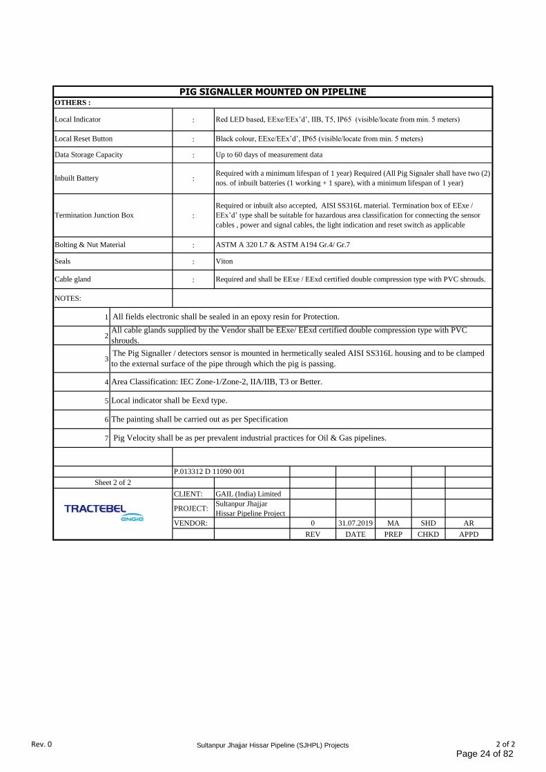
PIG SIGNALLER MOUNTED ON PIPELINE
:
:
:
:
:
:
:
:
NOTES:
1
2
3
4
5
6
7
CLIENT: GAIL (India) Limited
PROJECT:Sultanpur Jhajjar
Hissar Pipeline Project
VENDOR: 0 31.07.2019 MA SHD AR
REV DATE PREP CHKD APPD
Local Reset Button Black colour, EExe/EEx’d’, IP65 (visible/locate from min. 5 meters)
Data Storage Capacity Up to 60 days of measurement data
Local Indicator Red LED based, EExe/EEx’d’, IIB, T5, IP65 (visible/locate from min. 5 meters)
OTHERS :
All fields electronic shall be sealed in an epoxy resin for Protection.
Inbuilt BatteryRequired with a minimum lifespan of 1 year) Required (All Pig Signaler shall have two (2)
nos. of inbuilt batteries (1 working + 1 spare), with a minimum lifespan of 1 year)
Termination Junction Box
Required or inbuilt also accepted, AISI SS316L material. Termination box of EExe /
EEx’d’ type shall be suitable for hazardous area classification for connecting the sensor
cables , power and signal cables, the light indication and reset switch as applicable
Bolting & Nut Material ASTM A 320 L7 & ASTM A194 Gr.4/ Gr.7
Seals Viton
Cable gland Required and shall be EExe / EExd certified double compression type with PVC shrouds.
P.013312 D 11090 001
Sheet 2 of 2
Pig Velocity shall be as per prevalent industrial practices for Oil & Gas pipelines.
Local indicator shall be Eexd type.
All cable glands supplied by the Vendor shall be EExe/ EExd certified double compression type with PVC
shrouds.
The Pig Signaller / detectors sensor is mounted in hermetically sealed AISI SS316L housing and to be clamped
to the external surface of the pipe through which the pig is passing.
The painting shall be carried out as per Specification
Area Classification: IEC Zone-1/Zone-2, IIA/IIB, T3 or Better.
Rev. 0 Sultanpur Jhajjar Hissar Pipeline (SJHPL) Projects 2 of 2Page 24 of 82
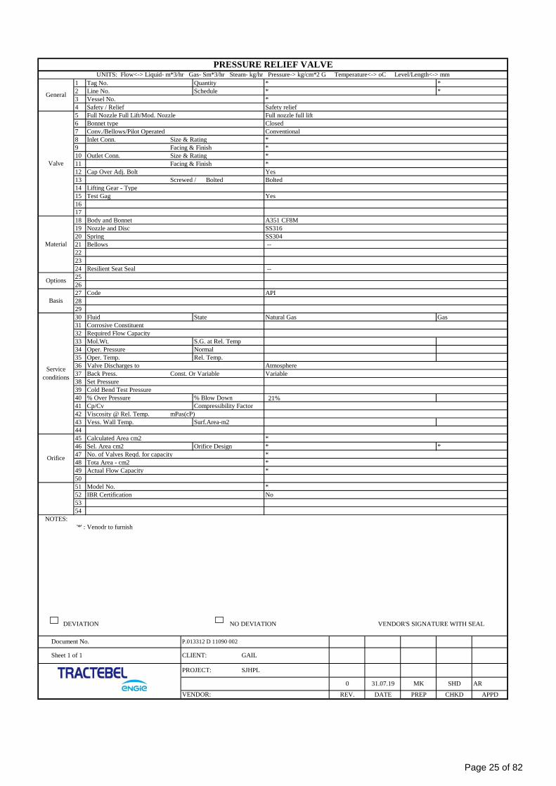
1 Tag No. Quantity * *
2 Line No. Schedule * *
3 Vessel No. *
4 Safety / Relief Safety relief
5 Full Nozzle Full Lift/Mod. Nozzle Full nozzle full lift
6 Bonnet type Closed
7 Conv./Bellows/Pilot Operated Conventional
8 Inlet Conn. Size & Rating *
9 Facing & Finish *
10 Outlet Conn. Size & Rating *
11 Facing & Finish *
12 Cap Over Adj. Bolt Yes
13 Screwed / Bolted Bolted
14 Lifting Gear - Type
15 Test Gag Yes
16
17
18 Body and Bonnet A351 CF8M
19 Nozzle and Disc SS316
20 Spring SS304
21 Bellows --
22
23
24 Resilient Seat Seal --
25
26
27 Code API
28
29
30 Fluid State Natural Gas Gas
31 Corrosive Constituent
32 Required Flow Capacity
33 Mol.Wt. S.G. at Rel. Temp
34 Oper. Pressure Normal
35 Oper. Temp. Rel. Temp.
36 Valve Discharges to Atmosphere
37 Back Press. Const. Or Variable Variable
38 Set Pressure
39 Cold Bend Test Pressure
40 % Over Pressure % Blow Down 21%
41 Cp/Cv Compressibility Factor
42 Viscosity @ Rel. Temp. mPas(cP)
43 Vess. Wall Temp. Surf.Area-m2
44
45 Calculated Area cm2 *
46 Sel. Area cm2 Orifice Design * *
47 No. of Valves Reqd. for capacity *
48 Tota Area - cm2 *
49 Actual Flow Capacity *
50
51 Model No. *
52 IBR Certification No
53
54
NOTES:
'*' : Venodr to furnish
DEVIATION NO DEVIATION VENDOR'S SIGNATURE WITH SEAL
PRESSURE RELIEF VALVEUNITS: Flow<-> Liquid- m*3/hr Gas- Sm*3/hr Steam- kg/hr Pressure-> kg/cm*2 G Temperature<-> oC Level/Length<-> mm
General
Valve
Material
Options
Basis
Service
conditions
Orifice
Document No. P.013312 D 11090 002
Sheet 1 of 1 CLIENT: GAIL
PROJECT: SJHPL
0 31.07.19 MK SHD AR
VENDOR: REV. DATE PREP CHKD APPD
Page 25 of 82
PTS- SCRAPER BARRELS
(PIG LAUNCHER/RECEIVER)
P.013312
D 11077
028
SULTANPUR JHAJJAR HISSAR PIPELINE (SJHPL) PROJECT
TRACTEBEL ENGINEERING PVT. LTD.
PTS – SCRAPPER BARREL
(PIG LAUNCHER/RECEIVER)
RERT
0 30.07.2019 Issued for Procurement SSA MS/NC AR
Rev. Date Description Prepared by Checked by Approved by
Page 26 of 82
PTS- SCRAPER BARRELS
(PIG LAUNCHER/RECEIVER)
P.013312
D 11077
028
Rev. 0 Sultanpur Jhajjar Hissar Pipeline (SJHPL) Project
Page 1 of 1
TABLE OF CONTENTS
1. SCOPE ...................................................................................................................................... 1
2. GENERAL REQUIREMENTS ...................................................................................................... 1
3. DESIGN DATA .......................................................................................................................... 1
4. MATERIALS .............................................................................................................................. 1
5. REFERENCE DOCUMENTS ........................................................................................................ 1
6. TECHNICAL REQUIREMENT ..................................................................................................... 2
7. WELDING ................................................................................................................................. 3
8. INSPECTION AND TESTING ..................................................................................................... 4
9. STANDARD OF ACCEPTABILITY ............................................................................................... 5
10. CLEANING, PAINTING & PROTECTIVE COATING .................................................................... 6
11. TRANSPORTATION .................................................................................................................. 6
12. MARKING ................................................................................................................................. 6
13. DOCUMENTATION .................................................................................................................... 7
14. CERTIFIED DRAWINGS ........................................................................................................... 7
15. VENDOR’s OBLIGATIONS ........................................................................................................ 8
16. BID CONDITIONS .................................................................................................................... 8
17. DELIVERY ................................................................................................................................ 8
18. WORKING SCHEDULE .............................................................................................................. 8
Page 27 of 82
PTS- SCRAPER BARRELS
(PIG LAUNCHER/RECEIVER)
P.013312
D 11077
028
Rev.0 Sultanpur Jhajjar Hissar Pipeline (SJHPL) Project Page 1 of 8
1. SCOPE
This specification covers the requirements for design, material procurement fabrication, inspection testing
and supply of launchers/ receivers installed at various stations in the pipe line Project.
Scope of supply include Pig Launcher/Receiver along with internal tray, pig handling device -
Removable type, Quick Opening End Closure (QOEC).
2. GENERAL REQUIREMENTS
All the equipment to be supplied must comply with the requirements of the latest edition of ASME B
31.8/ ASME Sec VIII Div.1 for the gas pig launcher and pig receiver.
The Launcher and Receiver shall be provided with pig tray, lifting devices and handling trolleys for pigs.
Following order of procedure shall be followed for any conflict in technical requirement.
1. Data sheet
2. This specification
3. Codes and standards
3. DESIGN DATA
As per pipeline pig launcher and pig receiver data sheets.
4. MATERIALS
Material of Pig Launcher & Receiver shall be as per Data sheet.
The Pig Launcher and Pig Receiver will be installed on saddle support only.
Notes:
1. Alternative equivalent materials may be used when approved by the OWNER OR OWNER’S
REPRESENTATIVE / Consultant.
2. The steel plates used in the construction of the Pig Launcher and Pig Receiver must be certified
materials as per specification.
3. All materials used in the manufacturing of Pig Launcher and Receiver assemblies shall be subject
to approval by the OWNER OR OWNER’S REPRESENTATIVE / Consultant. All pressure
containing components NPS 2 and larger shall have proven notch toughness meeting the
requirements of ASME Section VIII, paragraph UG-84, in the final heat treated condition Charpy
V- notch impact tests shall be performed as per the requirement of the Oil and line pipe data
sheets.
4. All branch outlets larger than NPDS 3 shall be extruded or reinforced saddle as per ASME B 31.8
Code.
5. The OWNER OR OWNER’S REPRESENTATIVE / Consultant has the right to request all the
necessary destructive and non – destructive material tests in order to verify that all the components
comply with the required specifications.
6. The costs of the above mentioned tests, materials, equipment, and personnel to be borne by the
SUPPLIER.
5. REFERENCE DOCUMENTS
5.1 Project Specifications and Data Sheets
1 Pig Traps Data Sheets, Codes and Standards
2 PMS
Page 28 of 82
PTS- SCRAPER BARRELS
(PIG LAUNCHER/RECEIVER)
P.013312
D 11077
028
Rev.0 Sultanpur Jhajjar Hissar Pipeline (SJHPL) Project Page 2 of 8
Pig launchers and receivers specified herein shall be designed, manufactured and tested in accordance
with the latest edition of the following codes and standards and / or others as applicable. These Codes and
Standards are the minimum requirements, and manufactured design shall meet or exceed them.
API5L API Specification for Line pipe
ASTM A350 LF2 Carbon and Low-Alloy Steel Forgings, Requiring Notch Toughness
Testing for Piping Components
ASTM A694F65/F56 Forging, High Strength Carbon Steel for Piping Components
ASTM A 105 Forging Carbon Steel for Piping Components
ASTM A 234 Piping Fitting of Wrought Carbon Steel and Alloy Steel for Moderated
and Elevated Temperatures
ASTM A516 GR 70 Pressure Vessel Plates, Carbon Steel, for Moderate and Lower-
Temperature Service
ASME Sec II Boiler and Pressure Vessel Code- Materials
ASME Sec V Boiler and Pressure Vessel Code- Non Destructive Testing
ASME Sec VIII Boiler and Pressure Vessel Code Div I- Pressure Vessels
ASME Sec IX Boiler and Pressure Vessel Code- Code Welding and Brazing
Qualifications
ASME B1.1 Unified Screw Threads
ASME B 16.5 Steel Pipe Flanges and Flanged Fittings
SME B16.9 Factory made Wrought Steel Butt Welding Fittings.
ASME B.16.11 Forges Steel Fittings, Socket Welding and Threaded
ASME B 31.4 Pipeline Transportation System for liquid and Hydrocarbons and other
Liquids
ASME B 31.8 Gas Transmission and Distribution Pipeline System
ASTM A20 General Requirements for steel plate for pressure vessels
ASTM A516 Carbon steel pressure vessel plates for moderate and low Temperature
service.
ASTM A106 Carbon steel seamless pipe for high temperature service
ASTM A193 Alloy steel and stainless steel bolting materials for high temperatures
ASTM A194 Carbon and alloy steel nuts for bolts for high pressure or temperature
services or both.
MSS-SP-75 High test wrought butt welding fittings
MSS-SP-44 Steel pipeline flanges
MSS-SP-97 Integrally Reinforced forged branch outlet fittings
IS 875 Part 3 Codes of practice for design loads ( other than earthquake ) for buildings
and structures
IS 1892 Codes for earth quake resistance design of structures
6. TECHNICAL REQUIREMENT
The pig launcher and pig receiver shall be suitable for launching and receiving pigs /
intelligent pigs.
Mechanical design of each pig launcher and pig receiver shall be as per ASME Sec VIII Div.1
/ASME B31.8. All the launcher/ receiver shall be horizontal type and shall be supported on 2
no. saddles suitably spaced and designed to withstand the maximum dead load including
pipeline reaction on barrel flange.
The launching and receiving barrels shall be bidirectional. Bidirectional Scraper
Launcher/Receiver shall be suitable for intelligent pigging.
Orientation of all the nozzles is indicative only and same shall be confirmed during Detailed
Engineering.
Each pig launcher and pig receiver assembly shall be equipped with a quick opening closure
with a davit so designed as to permit one man to load or remove pig from the assembly. The
closure hinge pin shall be vertical with the closure opening in a horizontal plane.
Page 29 of 82
PTS- SCRAPER BARRELS
(PIG LAUNCHER/RECEIVER)
P.013312
D 11077
028
Rev.0 Sultanpur Jhajjar Hissar Pipeline (SJHPL) Project Page 3 of 8
The quick closure shall be manufactured with a safety system as per ASME Sec VII Div.1,
UG35 (b) which grants the opening only when the pig launcher and pig receiver is not under
pressure. It shall be manually operated. The design shall allow opening or closing by one man
in a period of one (1) minute or less without the use of additional equipment.
Quick opening closure shall be Band lock / Clamp ring type. Pig traps shall be designed in
accordance ASME Section VIII Div.1 with corrosion allowance of 3mm. Material of QOEC
shall be similar to that of major barrel. QOEC shall be band lock type having 'O' ring with
ASME U stamp. The Scrapper Trap manufacturer shall have “U” stamping of fabrication yard.
Quick Opening Closure shall be ASME "U" stamped.
Screwed type or plug-in types of end closures are not permitted
Scraper trap shall be provided with suitable handling system for retraction, insertion &
launching of pigs including instrumented pigs (such as basket / tray; retracting rod/ mechanism
etc.) from the trap. Price of scraper trap shall be inclusive of pig handling system.
The pig receiving traps shall be equipped with a half internal removable filtering basket
consisting of a punched plate with at least five rows of drain holes. The filtering basket shall
slide on guides/rails or wheels and in all cases the material of the parts being in contact with
each other shall be of anti-spark type. The filtering basket shall be provided with suitable
stops. Lock bracket shall be provided to such that the basket does not slide within the trap.
Rear end of the basket shall be provided with suitable lug to enable retrieval of the basket by
hooks. The handling system (for inserting and retracting the scraper and instrumented pigs
from the trap) shall be complete with handling devices. In case any rails are required for
sliding of the handling system, the same shall be provided by the scraper trap manufacturer
The internal diameter of the pig launcher and pig receiver assembly shall have a smooth
continuous level surface and shall have the same diameter as the export pipeline.
The pig launcher and pig receiver shall have saddle mounting to create a fall towards the trap
door to a minimum 1:100. Vendor to provide suitable cleats for installation
7. WELDING
All nozzle attachment welds including added reinforcement shall be full penetration nozzle
less than or equal to 2” shall be attached with the barrel using weldolet.
All fillet welds shall be continuous.
The welders and the welding procedures shall be qualified and performed according to the
requirements of the ASME code, section IX. This shall be verified by the authorized Inspector.
Welding procedure specifications (WPS’s) together with the supporting procedure
qualifications records (PQR’s) shall be submitted INSPECTOR for review and acceptability
before commencement of fabrication.
Each WPS submitted should closely relate to the production weld it represents. The actual
joint preparation, fit up and weld consumables to be used shall be described.
When the ambient temperature is 00C and below, the base metal shall be preheated to 150C
minimum before welding unless a higher preheat temperature is dictated by the code.
All butt weld joints shall be welded with full penetration full fusion and double sides. All
nozzles to shell / head welds shall also be full penetration.
There is no opening to permit access for internal welding of the final closure scam, Gas
Tungsten Are Welding or other techniques, shall be used that will assure a quality root pass as
specified in code.
Electro slag or single pass Electro-gas process shall not be used to weld any components of
vessels.
Page 30 of 82
PTS- SCRAPER BARRELS
(PIG LAUNCHER/RECEIVER)
P.013312
D 11077
028
Rev.0 Sultanpur Jhajjar Hissar Pipeline (SJHPL) Project Page 4 of 8
All internal and external attachments shall be continuously welded, unless specified otherwise.
The maximum weld deposit per pass shall not exceed 6.5mm except root run.
All welding including tack welding and non-pressure parts welding shall be performed by a
welder qualified as per code.
No welding or weld repair is permitted on pressure parts after Post Weld Heat Treatment
(PWHT), unless specifically approved.
8. INSPECTION AND TESTING
All inspections shall be carried out by OWNER OR OWNER’S REPRESENTATIVE /
Consultant or approved third party inspection agency.
SUPPLIER shall advise the OWNER OR OWNER’S REPRESENTATIVE / Consultant with
two weeks advance notice, from the date of the test required on the traps in order to allow one
of the OWNER OR OWNER’S REPRESENTATIVE, representatives to witness the test.
SUPPLIER shall submit Inspection and Test Plant for OWNER OR OWNER’S
REPRESENTATIVE / Consultant, approval.
The following minimum inspections are required and shall be performed at the SUPPLIER’S
shop.
Visual inspection.
Dimensional check
Air testing of reinforcement pads prior to hydro testing.
Hydrostatic test at a pressure 1.5 times the design pressure for a period of at 4 (four) hours.
100% inspection of all longitudinal and circumferential weld scams for their entire length by
radiography.
100% UT of all main weld (longitudinal and circumferential) of the vessel body.
100% UT for vessel plate for lamination.
Magnetic Particle Inspection of all other welds.
All forgings shall be Wet Magnetic Particle Examined on 100% of the forged surfaces.
Method and acceptance shall comply with MSS-SP-53.
Inspection of weld ends intended for field welding over their entire length with Ultrasonic
testing.
Review of the material test certificates.
Operation of the quick release closure.
The Inspectors must witness all tests to certify the validity of the procedures.
The designated Inspectors have the authority to reject or make objections to any procedure, material,
or equipment that is not complying with the specified codes and practices.
8.1 Non destructive Examination
All non-destructive examination shall be performed by personnel qualified in accordance with
ASNT Recommended Practice SNT-TC-1A or equivalent. Personnel interpreting results of any non-
destructive testing method shall be qualified in accordance with Level II requirements of SNT-TC-
IA or equivalent.
The longitudinal scam will be nondestructively tested for final acceptance only after hydrostatic
testing except for weld repairs.
Page 31 of 82
PTS- SCRAPER BARRELS
(PIG LAUNCHER/RECEIVER)
P.013312
D 11077
028
Rev.0 Sultanpur Jhajjar Hissar Pipeline (SJHPL) Project Page 5 of 8
One (1) inch of each pipe end shall be examined around the periphery by an approved ultrasonic
method to check for lamination, pipe containing laminations greater then ¼ inch circumferentially
shall be rejected. All non-destructive examination shall be carried out in accordance with ASME
Section V and ASME Section VIII. All acceptance criteria shall be based on ASME Section VIII.
9. STANDARD OF ACCEPTABILITY
9.1 Dimensions
Internal Diameter and Out of Roundness.
9.2 Visual Inspection
All surfaces shall be free of nicks, dents, gauges, taps, are burns and other defects.
9.3 Non Destructive Inspections
Pig Launcher and pig receiver traps will not be accepted if any of the following defects are detected by
the ultrasonic or radiographic methods.
Cracks
Insufficient penetration or fusion
Laminations
Continuous occurrence, regardless of dimensions of undercuts, porosity gas pockets or slag
inclusions.
Undercuts exceeding 0.35 mm in depth and 25 mm in length.
Individual gas pockets exceeding 1.6 mm in diameter and/or concentrations of gas pockets with a
maximum diameter of 1 mm exceeding 6 per 4 cm2. Adjacent groups of two or more gas pockets,
which exceed 1 mm in diameter, shall be separated by at least 100 of sound material.
Slag inclusions that exceed 3 mm in width or 1.6 mm in depth and length.
VENDOR shall employ Non-destructive Test operators, qualified as required by code. VENDOR
shall also certify that each operator, engaged in NDT, is qualified to meet the code requirement.
The extent of radiography shall be in accordance with the most stringent requirements of relevant
code or vessel data sheet and this specification.
For vessels where butt weld seams are 100% radiographed, all other pressure containing welds and
all attachment welds to pressure containing parts shall be examined as follows (a) All
circumferential and longitudinal butt welds and butt welds joining heads, shells and nozzles shall
be fully radiographed (b) Nozzle to shell welds and pressure containing welds other than butt
welds shall be examined by the ultrasonic method, after PHWT (c) All root runs of longitudinal
and circumferential seams shall be examined by magnetic particle method or liquid penetrant
inspection method (d) All nozzle-to-shell welds, hold root runs and final nuts shall be examined
by magnetic particle method or liquid penetrant inspection method in addition to ultrasonic
method.
Are strikes on the pressure parts shall be avoided. When they occur, the surfaces shall be properly
conditioned to eliminate surface stress raisers and such surfaces, shall be examined by, either
magnetic particle or liquid penetrant method of examination.
Air and soapy water tests shall be performed on nozzle reinforcement pads by applying 1.05 kg/
cm2 (g) air for 5 minutes, subsequently reduce to 0.2 kg/cm2 g before applying soap solution.
Irrespective of code requirements, welds shall be free from all surface breaking defects.
Page 32 of 82
PTS- SCRAPER BARRELS
(PIG LAUNCHER/RECEIVER)
P.013312
D 11077
028
Rev.0 Sultanpur Jhajjar Hissar Pipeline (SJHPL) Project Page 6 of 8
10. CLEANING, PAINTING & PROTECTIVE COATING
All exterior surfaces in contact with the atmosphere under operating conditions must be cleaned
and painted according to the paint manufacturer’s standards suitable for the site conditions.
Cleaning and painting procedures is required to be approved by OWNER OR OWNER’S
REPRESENTATIVE.
The pig launcher/receiver shall be shot blasted and primed as follows.
Blast clean to ISO 8501-1, Grade Sa 2-1/2.
Painting shall be as per Design Basis of Pipeline of this project. (Document no. P.013312 D 11077
019, latest revision)
The inner surfaces must be free of loose particles lamination flakes, welding splatter, etc. They
also must be free of sharp edges or any protruding element that interferes with the free circulation
of the scrapper.
Unless otherwise specified, the VENDOR shall include the following for painting.
All internal and external surfaces of vessel shall be thoroughly cleaned to remove all loose mill
scales, rust, grease, dirt, weld spatters etc.
Internal coating, if specified in vessel data sheet shall be carried out as per the requirements of
internal coating material specification and the complete procedure shall be approved by OWNER
OR OWNER’S REPRESENTATIVE / Consultant before start of any work.
All machined and bright finish surfaces shall be coated with an easily removable corrosion
preventive.
The painting, as specified in vessel data sheets, shall be carried out as per the painting material
specification requirements and painting specification.
No painting or internal coating shall be applied before weld inspection leak test or hydrostatic test.
11. TRANSPORTATION
Care shall be taken to ensure that mechanical damage is not caused during handling and
transportation. Weld bevels shall be suitably protected against damage during handling and
transportation. All open ends shall be blind with wooden or plastic discs to prevent the ingress of
dirt or moisture.
Care shall be taken to ensure that wire ropes, chains or other handling devices do not come into
metallic contact with the launcher/ receiver. It is recommended that broad band, non-metallic
slings to be used to load/ unload and support the tee when in transit.
The protection, packing and shipping shall be subject to the approval of the OWNER OR
OWNER’S REPRESENTATIVE / Consultant.
12. MARKING
Each trap shall have a name plate clearly marked by the minimum following details:
Manufacturer name
Job number
Specification number
Year of production
Nominal diameter ( at flanged or welding end)
Maximum, design, operating and allowable pressures/ temperatures
Test pressure
Page 33 of 82
PTS- SCRAPER BARRELS
(PIG LAUNCHER/RECEIVER)
P.013312
D 11077
028
Rev.0 Sultanpur Jhajjar Hissar Pipeline (SJHPL) Project Page 7 of 8
Inspector stamp
Project Name-
CLIENT’s Name
Vendor to furnish name plate/ bracket Drawing. For OWNER OR OWNER’S REPRESENTATIVE /
Consultant approval
Transportation marking shall be painted with synthetic resin paint.
13. DOCUMENTATION
SUPPLIER shall provide a Manufacturer’s data report in compliance with their Supplier Document
requirement List (SDRL) for pig launchers and Receiver.
Complete material specification, including certificates of mechanical and chemical test.
Forming process with the indication of temperature at which the forming process has been
performed.
Detailed description of welding process including type, size and grade of filler material and flux,
welding speed, electrical characteristics, number of weld passes, specific energy input ( in J/cm),
hardness test covering critical sections of welds.
Heat treatment after forming and welding.
Test reports on radiographic and ultrasonic inspections as well as on the hydrostatic test complete
with all diagrams.
Protection coating.
Quality control forms (Certified by SUPPLIER’s third party).
- Check of dimensions
- Verification of materials
- NDT Inspection
- Hydrostatic test
- Painting/ Coating
- Inspection Release Note (Released for Shipment) etc.
Quality Assurance Plan and Procedures.
Operation and maintenance instructions.
14. CERTIFIED DRAWINGS
SUPPLIER shall furnish drawings and /or specifications to the OWNER OR OWNER’S
REPRESENTATIVE for comments/ approval
It is understood that the suggestion, recommendations for design, variations and fabrication changes
issued by the OWNER OR OWNER’S REPRESENTATIVE / Consultant do not relieve the
CONTRACTOR from any responsibilities concerning the compliance with all requirements of this
Specification and/or from the fulfillment guaranties.
The drawings shall at least contain the following information
Material (chemical composition, mechanical strength properties).
Maximum, design, operating and allowable pressures/ temperatures.
Maximum test pressure.
Dimensions
Page 34 of 82
PTS- SCRAPER BARRELS
(PIG LAUNCHER/RECEIVER)
P.013312
D 11077
028
Rev.0 Sultanpur Jhajjar Hissar Pipeline (SJHPL) Project Page 8 of 8
Welding procedure for each type of weld, including weld joint factor.
15. VENDOR’s OBLIGATIONS
Submit construction drawings to be approved by the OWNER OR OWNER’S REPRESENTATIVE /
Consultant. Perform all the tests necessary and submit the results for the OWNER OR OWNER’S
REPRESENTATIVE / Consultant’s approval to assure the quality.
Submit for the OWNER OR OWNER’S REPRESENTATIVE / Consultant approval the welding
procedures and welders qualifications. Communicate to the OWNER OR OWNER’S
REPRESENTATIVE / Consultant the performance of any test 10 days in advance to permit the
presence of the authorized OWNER OR OWNER’S REPRESENTATIVE / Consultant Inspector.
16. BID CONDITIONS
For the supply of each of the equipment items indicated in this specification and supporting Data sheets/
purchase requisition including supply of all materials.
17. DELIVERY
At the place indicated in the OWNER OR OWNER’S REPRESENTATIVE / Consultant’s Purchase
Order.
18. WORKING SCHEDULE
VENDOR shall submit to the OWNER OR OWNER’S REPRESENTATIVE / Consultant, a detailed
“working schedule” that will include the engineering fabrication, purchasing, testing and delivery.
Page 35 of 82
FITTINGS & FLANGES P.013312
D 11077
025
SULTANPUR JHAJJAR HISAR PIPELINE (SJHPL)
PROJECT
TRACTEBEL ENGINEERING PVT. LTD.
PTS - FITTINGS & FLANGES
(Up to 12” Size)
P.013312 D 11077 025
0 30.07.2019 Issued for Procurement SSA MS AR
Rev. Date Subject of Revision Prepared By Checked By Approved By
Page 36 of 82
FITTINGS & FLANGES P.013312
D 11077
025
Rev. 0 Sultanpur Jhajjar Hisar Pipeline (SJHPL) Project Page 1 of 1
TABLE OF CONTENTS
1.0 GENERAL ............................................................................................................................ 1
2.0 DESIGN AND CONSTRUCTION ........................................................................................... 3
3.0 MATERIALS ........................................................................................................................ 6
4.0 FABRICATION AND TEST ................................................................................................... 7
5.0 UPGRADING FROM 3.1 TO 3.2 CERTIFICATE .................................................................... 9
6.0 INSPECTION .................................................................................................................... 13
7.0 CORROSION PROTECTION............................................................................................... 14
Page 37 of 82
FITTINGS & FLANGES P.013312
D 11077
025
Rev. 0 Sultanpur Jhajjar Hisar Pipeline (SJHPL) Project Page 1 of 19
1.0 GENERAL
This specification describes the requirements of fittings and flanges to be installed on Sultanpur Jhajjar
Hisar Pipeline and particularly in the despatch stations, receiving stations and sectionalizing valve stations.
This specification also describes the examinations and upgrading tests to be performed for obtaining a 3.2
certificate on the standard new fittings and flanges or taken out of stock with a 3.1 certificate.
The fittings have to be delivered in accordance to the particular specification:
Codes, Norms and standards (latest revision); but not limited to:
ASME B16.5 Pipe flanges and flanged fittings
ASME B16.9 Factory - made wrought steel butt welding fittings.
ASME B 16.11 Forged steel fittings
ASME B16.28 Wrought steel butt welding short radius elbows and returns
ASME B31.3 ASME code for process piping.
ASME B31.4 Pipeline transportation system for Liquid hydrocarbons
ASME B31.8 Gas transmission and distribution piping systems.
ANSI B36.10 Welded and seamless wrought steel pipe
ASTM A 105/
A 105 M
Forging, carbon steel, for piping components.
ASTM A 203 Pressure vessel plates, alloy steel, nickels
ASTM A 234/
A 234 M
Piping, fittings of wrought carbon steel and alloy steel for moderate and elevated
temperatures
ASTM A 333 Seamless and welded steel pipe for low temperature
ASTM A 350/
A 350 M
Forging, carbon and low alloy steel, requiring notch toughness testing for piping
components.
ASTM A 370 Mechanical testing of steel products.
ASTM A 420/
A 420 M
Piping fittings of wrought carbon steel and alloy steel for low temperature service.
ASTM E 112 Standard methods for determining the average grain size.
MSS SP 25 Standard marking system for valves, fittings, flanges and unions.
MSS SP 55 Quality standard for steel castings for valves, flanges and fittings and other piping
components (visual method).
MSS SP 75 Specification for high test wrought butt welding fittings.
ASME Boiler and Pressure Vessel code.
DIN 2413 Design of Steel Pressure Pipes
EN 10204 Type of Inspection documents
ISO 148 Metallic Material - Charpy Pendulum impact test
ISO 9001 Quality management standard
Page 38 of 82
FITTINGS & FLANGES P.013312
D 11077
025
Rev. 0 Sultanpur Jhajjar Hisar Pipeline (SJHPL) Project Page 2 of 19
The present specification can confirm, complete or alter certain characteristics or tolerances of existing
laws or specifications.
In his offer, the manufacturer or vendor shall specify all proposed modifications or alternatives to the
present specification. In all cases, each modification has to be submitted to the pipe laying contractor and
the Client/Consultant. The complete upgrading cycle shall be supervised by a pipe laying contractor. All
consequences after eventual order for non respect of this obligation are at the manufacturer's charge and
responsibility.
A valid copy of the ISO 9001 certificate shall be included in the offer.
Before the order is placed, a technical audit will take place with pipe laying contractor/ Client.
The manufacturer's specification of the steel, the manufacturing procedure itself and the laboratories in
which testing takes place, shall be approved and registered by the pipe laying contractor. Valid approval
certificates must be available.
The pipe laying contractor shall verify the control equipment of the manufacturer, its calibration and the
points at which it is located. If during the control of the fittings certain problems arise the pipe laying
contractor agent may demand supplementary tests at the cost of the manufacturer.
At all times while work on the contract of the Client is being performed, the inspector representing the
Client shall have free entry to all parts of the manufacturer's facilities and those of all subcontractors, who
are involved in the manufacturing of the fittings. All reasonable facilities shall be afforded to the inspector
to satisfy him that the product is being furnished in accordance with these specifications. All tests and
inspections called for by these specifications will be made in the manufacturer's plant prior to shipment and
at the manufacturer's expense, unless otherwise, and shall be conducted as not to interfere unnecessarily
with the operations of the manufacturer's plant. The manufacturer shall notify the Client prior to
completion or shipment of all fittings requiring such inspection.
Eventual interpretations and deviations to this specification by the Manufacturer shall be requested by
writing in his offer with detailed justification and approved by the Client/Consultant and the Authorised
pipe laying contractor before eventual order to the Manufacturer. The latter is responsible and shall
indemnify the Client/Consultant for any damage resulting from the non-respect of this obligation.
An approval of documents can never be considered as an acceptance of deviations or relaxations to
requirements. A deviation is only possible after specific request to the Client.
1.1. Glossary
Client shall mean GAIL (India) Limited
Manufacturer means the Manufacturer of the Fittings &
Flanges as well as its sub-contractor(s)
PTS means the present «Particular Technical Specification P.013312
D 11077 025 » and all its appendices, if any.
Pipe Laying Contractor/Contractor party which carries out all or part of Engineering, Procurement,
Construction, Pre-commissioning & Commissioning of the project.
It shall mean Pipe Laying Contractor in the present context.
Third Party
Inspection Agency (TPIA) means the Inspection Agency to be appointed by the Vendor
Consultant /Owner Shall means TRACTEBEL Engineering Pvt. Limited /
Representative The entity of the Client or the company nominated by the Client to
design the natural gas transport or distribution system and to specify
the equipment
Page 39 of 82
FITTINGS & FLANGES P.013312
D 11077
025
Rev. 0 Sultanpur Jhajjar Hisar Pipeline (SJHPL) Project Page 3 of 19
2.0 DESIGN AND CONSTRUCTION
2.1 The pressure temperature ratings for tee, weldolets, elbows and flanges shall be calculated respectively in
accordance with ANSI B31.8, DIN2413 and ANSI B16.5. For all other types of fittings (caps, reducers,
nipple) ASME section VIII shall apply.
The standard dimension shall be in accordance
Flanges such as weld neck flanges and blind flanges shall conform to the requirements as follows :
- ASME B16.5 upto sizes DN 600 mm (24") excluding DN 550 mm (22"),
- MSS-SP-44 for sizes DN 550 mm (22").
With ANSI B16.9 for the tees, reducers and elbows (except for short radius elbows which should be in
accordance with ANSI B16.28)
With ANSI B 16.9 for the caps,
With ANSI B 36.10 for the nipples,
And with ANSI B16.5 / MSS SP 44 for the flanges.
2.2 The temperature range as follows:
For above ground Services (CS) : -20°C to +65°C
For above ground Services (LTCS) : -45°C to +65°C
For Underground Services : -20°C to +60°C
The Design pressure is 98 barg.
2.3 The wall thickness shall meet the following requirements:
2.3.1 The maximum allowable stress in the base material and in the weld shall be equal to fifty per cent (50%) of
the minimum yield strength guaranteed by the specification of the steel used.
2.3.2 The minimum wall thickness must be greater than the following:
a. Thickness calculated in line with requirements given in ASME B 16.9 Para 2.2
b. Nominal Thickness of pipe
Thickness calculation is to be submitted to Owner/Owner’s Representative for prior approval before
manufacturing.
2.3.3 If the fitting has yield strength lower than the yield strength of the pipe to which it is intended to be
welded, the wall thickness in each zone of the fitting is at least equal to the largest value "tr" of either.
The specified pipe wall thickness times the ratio of the minimum yield strength guaranteed by the
standard of the steel of the pipe and the minimum yield strength guaranteed by the standard of the steel
of the fitting;
The absolute minimum thickness required by the applicable code(s).
2.3.4 The specified pipe wall thickness and grade (with reference to the equivalent grade in ASTM spec. or API
5L spec.) with which the fitting and flange is intended to be used is specified in the piping material
specification.
Fittings such as tees, elbows, reducers, etc. shall be either welded or seamless type. All welded fittings
shall be subjected to heat treatment. All fittings (except weldolets) shall comply with
The requirements of MSS-SP-75. Fittings such as weldolets etc. shall be manufactured in accordance with
MSS-SP-97.
Welded pipes used for fittings shall be LSAW type only.
Page 40 of 82
FITTINGS & FLANGES P.013312
D 11077
025
Rev. 0 Sultanpur Jhajjar Hisar Pipeline (SJHPL) Project Page 4 of 19
2.3.5 The thickness at the welding end shall not exceed 1.5 times the nominal wall thickness of the pipe to be
matched.
2.3.6 All the above requirements also apply to the welding ends of the flanges.
2.4 The manufacturer shall submit for approval to the Pipe Laying contractor and to the Client the dimensional
drawings, calculations, and the material part lists for all the types of fittings and flanges. All the documents
must be identified with the Client's order number.
2.5 The design shall take into consideration performance requirements prescribed in paragraph 2.6.
The design of tees, reducers or elbows must be established, by proof testing, in accordance with par. 2.7.
The design of the other fittings must be established by mathematical analysis according to ASME code.
2.6 All fittings under this specification shall be designed to withstand a field hydrostatic test pressure with non
corrosive water, after installation, during 24 hours at a following pressure level:
Minimum: P = 1.5 MOP
Where:
P = hydrostatic test pressure, bar
MOP = maximum operating pressure = 91barg.
The pressure level will however not exceed 1.9 MOP for the fittings and 1.5 times the 38°C pressure
rating for the flanges.
2.7 DESIGN PROOF TEST
This applies to fitting only and not to flanges.
2.7.1 In addition to the requirements of par. 2.3.1 to 2.3.4 proof tests shall be made as evidence of the adequacy
to the design references. Records of design or successful proof tests shall be available at the facility for
inspection by the Client and copy shall be added to the Certified Material Test Report (CMTR, par. 6.3.).
2.7.2 Unless otherwise agreed upon between manufacturer and Client, the only required proof test is a bursting
strength test.
2.7.2.1 Prototype fittings, representatives of production, selected for test shall be identified as to material, grade,
and lot, including heat treatment. They shall be inspected for dimensional compliance to this standard.
2.7.2.2 Straight seamless or welded pipe sections, whose calculated bursting strength is at least as great as that
calculated for the fittings, shall be welded to each end of the fitting to be tested. Any internal misalignment
greater than 0.06 inch (1.6 mm) shall be reduced by taper boring at a slope not over 1:3. Length of pipe
sections for closures shall be at least twice the pipe O.D. Shorter lengths may be used as follows:
The assembly must withstand at least 110 % of the pressure computed in 2.7.2.3.
Minimum length of pipe shall be one pipe O.D. for sizes NPS 8" and smaller.
Test fluid shall be water or other liquid used for hydrostatic testing.
2.7.2.3 Hydrostatic pressure shall be applied until the fitting ruptures. The actual test pressure prior to rupture
must at least be equal to the adjusted proof test pressure defined as follows:
P (adj.) = P x S act
s
( .)
where
P (adj.) = the adjusted proof test pressure, bar
P = the computed proof test pressure at burst of any part of the assembly, bar
S = minimum specified tensile strength of the pipe for which the fitting is intended to be
used, N/mm2
Page 41 of 82
FITTINGS & FLANGES P.013312
D 11077
025
Rev. 0 Sultanpur Jhajjar Hisar Pipeline (SJHPL) Project Page 5 of 19
S (act.) = the actual tensile strength of the material of the test fitting (determined on specimen
representative of the test fitting), N/mm2
The computed proof test pressure shall be determined as follows:
which refers to the pipe which the fitting's marking identifies and, where
P = 20S t
D
.
where,
P = Computed bursting pressure of the pipe, bar
S = Minimum specified tensile strength of the pipe, N/mm2
t = Nominal pipe wall thickness, mm
D = Specified outside diameter of pipe, mm
2.7.2.4 As an alternate, if the pipe ruptures, or if sufficient pressure to rupture any part of the assembly cannot be
attained, the test pressure is acceptable if a final test pressure is at least 105 % of the adjusted proof test
pressure.
2.7.3 A successful proof test on a prototype fitting, selected as required in subsection 2.7.2.1., may be used to
qualify other fittings to the extent described herein.
2.7.3.1 One test fitting may be used to qualify similar designs which shall not be smaller than one-half nor larger
than two times the size of the test fitting.
2.7.3.2 The test on a non-reducing fitting qualifies reducing fittings of the same pattern.
2.7.3.3 The untested fitting must have a t/D ratio neither less than one-half nor more than three times the t/D of the
test fitting.
2.7.3.4 The pressure retaining capacity of a fitting, made of various grades of steel, will be essentially directly
proportional to the tensile properties of the various grades. Hence, it is necessary to test a prototype in only
a single grade to prove the geometric design of the fitting.
2.7.3.5 A test on a prototype elbow qualifies elbows having longer radii than the test fitting providing they qualify
under 2.7.3.1 and 2.7.3.3.
2.7.3.6 A change in design from seamless fitting to fitting containing (a) seam weld(s) require(s) an appropriate
prototype test. A change of location of the seam weld requires a separate prototype test. Any deviation
must be submitted for approval to the pipe laying contractor.
2.7.4 If the manufacturer cannot give the certificate of prototype bursting test, the design of fittings shall be
verified as follows.
A prototype must withstand during 24 hours 1.4 times the maximum operating pressure (M.O.P).
The prototype is considered to be agreed upon if the deformations measured during the test at 1.4
X M.O.P. shows that the stress does not exceed 70 % of the minimum guaranteed yield strength
of the fitting.
The certificate of this prototype qualifies in the same limits than par. 2.7.3.
2.8 FITTING DIMENSIONS
One of the principles of this standard is the maintenance of a fixed position for the welding ends with
reference to the centreline of the fittings or the overall dimensions, as the case may be.
Dimensional standards will be in accordance with §2.1.
2.9 FITTING AND FLANGES TOLERANCES
Page 42 of 82
FITTINGS & FLANGES P.013312
D 11077
025
Rev. 0 Sultanpur Jhajjar Hisar Pipeline (SJHPL) Project Page 6 of 19
2.9.1 Tolerances for welding ends, out-of-roundness at the welding ends and inside diameter at the bevel are
shown hereafter. Other tolerances wall thickness are as per corresponding codes: ANSI B16.9 standard
and for short radius elbows ANSI B16.28 standard.
2.9.2 Welding ends
The welding end and bevel shall be in accordance with Figure 1 for wall thickness up to 20.0 mm ; for
thicker walls, refer to Figure 2. The welding end land of the fitting & flanges shall be machined flat and
shall not vary from the plane by more than 0.03 in (0.8 mm) at any point. If a fitting & flange has a
thickness unequal to the pipe with which it is intended to be used, the welding end preparation at the joint
has to conform with Figure 3.
2.9.3 Out-of-roundness at the welding ends
The out-of-roundness, defined as the difference between the maximum and the minimum inside diameter at
the welding ends shall not exceed 1 % of the specified inside diameter for sizes NPS 4 and smaller.
Fittings & flanges NPS 4 and larger shall be machined true round.
2.10 INSIDE DIAMETER
The inside diameter at any place at end (bevel) shall be the following:
NPS Tolerance of inside Ø at end (mm)
1/2" – 12” + 1.6 - 0.4
(1) The tolerance refers to variation from nominal I.D. calculating by (O.D. nom. - 2 t nom.).
(2) Flange Bore to match with I.D. of the pipe.
3.0 MATERIALS
3.1 The steel used in the manufacture of fittings & flanges shall be selected by the manufacturer and submitted
for approval to the Client and the pipe laying contractor at the time of the offer. The manufacturer shall fill
in the data sheet.
3.2 The chemical composition of the steel meets the requirements of Table 1.
3.3 The steel used has tensile properties conforming to the requirements prescribed in the ASTM standards.
3.4 The ratio of yield strength to tensile strength shall not exceed 0.90.
3.5 The material for fittings shall consist of blooms, billets, slabs, forging quality bar, plate, seamless or fusion
welded tubular products with filler metal added.
3.6 The steel shall be fully killed, fine grain practice.
3.7 The steel used shall be suitable for field welding to other fittings, pipes, flanges, or valves manufactured
under ASTM specifications A333, A350, A352, A381, A420, A694, A707 or API standards specifications
5L, 6D, 605 or MSS standards SP-44, SP-72, SP-75, EN 10208-2 in line with Piping Specification 6C1
attached with the tender document.
3.8 If preheating of the material is required to ensure proper weldability under normal field conditions, the
manufacturer shall state so in the offer, specifying preheat requirements and if accepted by the Client this
shall be permanently indicated on the fitting & flanges.
3.9 The Manufacturer must deliver a certificate EN 10204 (3.1 for upgrade fitting & flange; 3.2 if new), stating
the quality, the mechanical properties (yield strength, tensile strength, percent elongation, impact test,
chemical analysis, the process of manufacture and the marking (for example the heat number of material)
of the steel.
Page 43 of 82
FITTINGS & FLANGES P.013312
D 11077
025
Rev. 0 Sultanpur Jhajjar Hisar Pipeline (SJHPL) Project Page 7 of 19
3.10 Chemical Composition
3.10.1 For each heat the manufacturer shall check a chemical analysis of the steel (see Table 1).
3.10.2 Check analysis
Carbon equivalent shall be computed by the following equation:
C.E. = C + Mn
6 +
5
VMoCr +
Ni Cu
15
And shall not exceed 0.43
4.0 FABRICATION AND TEST
For all forging materials, the specimen shall be taken from the integral part of the forging.
The par.4.1 to 4.2 are only applicable on welded fittings.
4.1 WELDING FABRICATION
4.1.1 All welds and repair welds shall be performed according to written procedures. The welding procedure
must be submitted for approval to the pipe laying contractor before any fabrication.
Only qualified & approved welders and welding operators shall be used in production.
4.1.2 The joints shall be furnished in accordance with the requirements of Section VIII of ASME Boiler and
Pressure Vessel Code.
4.1.3 Machine welding shall be done by an electric process, preferably by submerged arc.
4.1.4 All butt welds shall have full penetration. Submerged arc machine welding shall be done with at least one
pass from the inside, except when accessibility makes this impossible, then a manual or machine root bead
may be employed provided that a visual inspection of the root bead is possible. Backing rings shall be not
used.
4.1.5 Repair, chipping or grinding of welds shall be done in such a manner as not to gouge, groove, or reduce
the original metal thickness by more than 6 1/2 % of nominal specified wall.
4.1.6 Except for bar in the tees, fillet welds shall not be permitted.
4.1.7 Welded-on braces, if used, should be removed before heat treatment and the weld spot shall be repaired
and ground flush and smooth. However, when braces are required for heat treatment, they shall be cut out
and the surface shall be ground flush and smooth after heat treatment. Except for bar in the tees, welding
shall not be permitted after heat treatment. The ground areas shall be inspected by magnetic particle or
liquid penetrant testing.
4.2 WELDING PROCEDURES
4.2.1 All welds, repair welds and repair by welding shall be performed according to written procedures. These
welding procedures shall be qualified according to the requirements of the ASME Boiler and Pressure
Vessel Code, Section IX.
The welding procedure tests are required on material which is on the high side of the chemistry
specification.
The manufacturer shall maintain a weld record of the procedure and performance test results. The test
coupons shall be submitted to the same fabrication and heat treatment as the actual fittings.
The welding procedure qualification must include an impact test set in the weld and in the HAZ with
requirements of paragraph 5.1.2 and a macrographic examination described in paragraph 4.2.2. These tests
shall be performed after eventual final heat treatment.
4.2.2 Macrographic examination: the etched surface of the macro test specimen viewed macroscopically must
display the image of a well performed welded joint with sufficient penetration, free from linear defects and
important inclusions. In case of doubt, the etched surface must be examined microscopically and
additional macroscopical examinations of other areas may be required.
Page 44 of 82
FITTINGS & FLANGES P.013312
D 11077
025
Rev. 0 Sultanpur Jhajjar Hisar Pipeline (SJHPL) Project Page 8 of 19
The macrographic examination will include hardness measurements in the weld and the HAZ. The hardness
will not exceed the values measured on the parent metal by more than 80 points for the welds and 100 point
for HAZ, with an absolute maximum of 350HV10.
The acceptance of inclusions can be decided upon with the NDE of the welded plates (see paragraph 5.3).
4.2.3 Transverse guided bend test
4.2.3.1 Test method
Transverse weld test specimens shall be subjected to face and root guided bend tests. The specimens shall
be approximately 1.5 in (38 mm) wide, at least 6 in (152 mm) long with the weld at the centre, and shall be
machined in accordance with Figure 4. The face bend specimen shall be bent with the inside surface of the
pipe against the plunger, and the root bend specimen with the outside surface against the plunger. The
dimensions of the plunger for the bending jig shall be in accordance with Figure 5 and the other dimensions
shall be substantially as shown in Figure 5.
The manufacturer shall use a "jig" based on this dimension or a smaller dimension at this option.
4.2.3.2 Test specimen
The weld bend test specimens, as described hereabove shall be cut from the coupon. The specimens may be
taken from a fitting or from sample plates as described in par. 4.2.3.1.
4.2.3.3 Acceptance criteria
The bend test shall be acceptable if no cracks or other defects exceeding 0.12 in (3.2 mm) in any direction
are present in the weld metal or between the weld metal and the fitting metal after the bending. Cracks
which originate along the edges of the specimen during testing and which are less than 0.25 in (6.4 mm)
measured in any direction, shall not be considered unless obvious defects are observed.
4.2.3.4 Retest
If either test fails to conform to specified requirements, the manufacturer may elect to make retests on two
additional specimens from the same lot, each of which shall conform to the requirements specified
hereabove. If any of these specimens fail to conform to the requirements, the welding procedure
qualification test is not accepted.
(*) A lot consists of all fittings/flanges from one heat of steel with same initial wall thickness, from the
same furnace charge for final normalizing heat treatment, from the same shape and the same main pipe
dimension.
4.2.4 Number of tests
The nature and number of tests are specified in the Table below and only one retest is allowed.
Specification test Number
Non destructive test par. 5.3. par. 5.3
X-ray and U.S. testing par. 5.3 par.5.3.
Destructive test All specimens shall be taken transverse to the weld
Tensile par. 5.1.1. 2
Bend test Face par. 4.2.3. 2
Root par. 4.2.3 2
Impact Weld par. 5.1.2. 1 set of 3 specimens
HAZ par. 5.1.2. 1 set of 3 specimens
Macrographic examination par. 4.2.2 1
Page 45 of 82
FITTINGS & FLANGES P.013312
D 11077
025
Rev. 0 Sultanpur Jhajjar Hisar Pipeline (SJHPL) Project Page 9 of 19
4.3 Normalising Heat Treatment
Start & stop temperature chart shall be signed by TPIA, also power failure log shall be maintained.
4.3.1 After forming and welding, all fittings & flanges shall be heat treated by normalising. Normalising shall be
carried out in such a way that the base material acquires a fine grained perlitic structure. If the
manufacturer can give proof by qualified manufacturing procedure that after forming, the steel of the
fitting & flanges has a homogeneous fine grained perlitic structure, he can ask for a derogation supported
by technical file to the Client and to the pipe laying contractor.
The normalizing procedure requires the approval of the pipe laying contractor. Good care shall be taken to
avoid direct contact of the flames with the material to be heated.
During the normalizing period, the temperature of the heat treatment lot shall be automatically recorded by
a sufficient number of thermocouples attached to the material surface. The thermocouples shall be
adequately protected against the influence of heat radiation. Temperature variations shall be within ±
20°C. The manufacturer shall furnish time temperature charts of each heat treatment lot. The fittings &
flanges belonging to each treatment lot shall be specified on the charts. Temperature measurements by
other means are permitted only if approved by the pipe laying contractor.
4.3.2 The fine grained perlitic structure of the steel shall be verified by at least one micrographic examination per
lot (definition in §4.2.4), according to ASTM E 112. The grain size shall be in the range of 8 to 12.
4.3.3 The manufacturer shall include in the CMTR data of this treatment.
5.0 UPGRADING FROM 3.1 TO 3.2 CERTIFICATE
5.1 Mechanical Tests
The following mechanical tests shall be performed by the vendor under the supervision of the PIPE
LAYING contractor and the certificates shall be added to the CMTR.
Test specimens may only be cut after a marking transfer by the Authorised PIPE LAYING contractor. All
the tests shall be performed after final heat treatment.
Certification requirements to comply with EN 10204 – 3.2 certificates shall issued by TPIA
5.1.1 Tension test
5.1.1.1 Requirements
The material shall be in conformance with the ASTM standards and the ratio of yield stress to tensile stress
shall not exceed 0.90.
For fittings containing welds, the fracture must be outside of the weld. If there is a fracture in weld or
HAZ, the tensile strength shall at least meet the requirements for tensile properties as per ASTM standards.
5.1.1.2 Test specimen
The test specimen shall represent all forgings from the same lot. Test specimens shall be taken from the
fitting after final heat treatment or from a piece of pipe or plate of the same nominal thickness, same heat
of steel from which the fitting is made and which has been heat treated in a lot with any of the fitting(s) it
represents. For welded fittings, this coupon (piece of pipe or plate) shall contain a weld in prolongation of
the weld of the fitting.
5.1.1.3 Number of tests
For fittings NPS 2 and greater the following number of test shall be performed:
Base material : one tension test
Weld : one tension test
5.1.1.4 Test locations and orientations
For welds, the test specimen shall be orientated transversally to the weld. For base material, test specimens
shall be orientated transversally and if this orientation is not feasible, it shall be orientated longitudinally.
Page 46 of 82
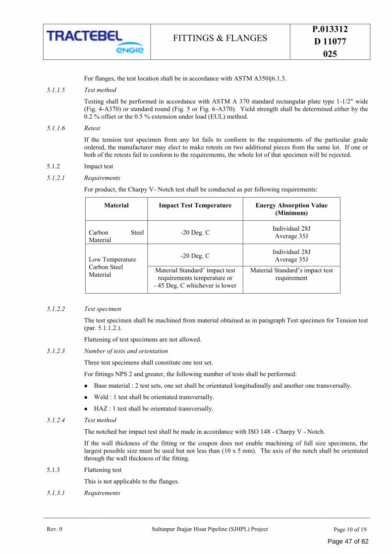
FITTINGS & FLANGES P.013312
D 11077
025
Rev. 0 Sultanpur Jhajjar Hisar Pipeline (SJHPL) Project Page 10 of 19
For flanges, the test location shall be in accordance with ASTM A350§6.1.3.
5.1.1.5 Test method
Testing shall be performed in accordance with ASTM A 370 standard rectangular plate type 1-1/2" wide
(Fig. 4-A370) or standard round (Fig. 5 or Fig. 6-A370). Yield strength shall be determined either by the
0.2 % offset or the 0.5 % extension under load (EUL) method.
5.1.1.6 Retest
If the tension test specimen from any lot fails to conform to the requirements of the particular grade
ordered, the manufacturer may elect to make retests on two additional pieces from the same lot. If one or
both of the retests fail to conform to the requirements, the whole lot of that specimen will be rejected.
5.1.2 Impact test
5.1.2.1 Requirements
For product, the Charpy V- Notch test shall be conducted as per following requirements:
Material Impact Test Temperature Energy Absorption Value
(Minimum)
Carbon Steel
Material
-20 Deg. C Individual 28J
Average 35J
Low Temperature
Carbon Steel
Material
-20 Deg. C Individual 28J
Average 35J
Material Standard’ impact test
requirements temperature or
- 45 Deg. C whichever is lower
Material Standard’s impact test
requirement
5.1.2.2 Test specimen
The test specimen shall be machined from material obtained as in paragraph Test specimen for Tension test
(par. 5.1.1.2.).
Flattening of test specimens are not allowed.
5.1.2.3 Number of tests and orientation
Three test specimens shall constitute one test set.
For fittings NPS 2 and greater, the following number of tests shall be performed:
Base material : 2 test sets, one set shall be orientated longitudinally and another one transversally.
Weld : 1 test shall be orientated transversally.
HAZ : 1 test shall be orientated transversally.
5.1.2.4 Test method
The notched bar impact test shall be made in accordance with ISO 148 - Charpy V - Notch.
If the wall thickness of the fitting or the coupon does not enable machining of full size specimens, the
largest possible size must be used but not less than (10 x 5 mm). The axis of the notch shall be orientated
through the wall thickness of the fitting.
5.1.3 Flattening test
This is not applicable to the flanges.
5.1.3.1 Requirements
Page 47 of 82
FITTINGS & FLANGES P.013312
D 11077
025
Rev. 0 Sultanpur Jhajjar Hisar Pipeline (SJHPL) Project Page 11 of 19
Flatten to 1/3 original O.D. without cracks or breaks in the fitting, continue flattening until meeting
opposite walls of the fitting.
No evidence of lamination of burnt metal may develop during entire test.
5.1.3.2 Test specimen
The test specimen represents all the fittings from the same heat of steel of the same shape and of the same
main pipe dimension of the fittings.
5.1.3.3 Number of tests
For fittings size lower than 2” one flattening test shall be made per test specimen.
5.1.4 Retreatment
If the result of the mechanical tests does not conform to the requirements specified in par. 5.1.3.1., the
manufacturer, with the acceptance of the Client and the pipe laying contractor, may reheat treat the fittings
as applicable and repeat all the tests specified.
5.2 Chemical Analysis
For each lot/item a new chemical analysis of the steel shall be done.
The chemical analysis shall conform to the ASTM requirements specified in the specification.
The carbon equivalent shall be computed by "check analysis": see par. 3.10.2 with C.E. 0.43.
The reports shall be added to the CMTR reports and approved by the pipe laying contractor.
5.3 Non Destructive Examinations (NDE)
The following mechanical tests shall be performed by the vendor under the supervision of the pipe laying
contractor and the certificates shall be added to the CMTR.
5.3.1 Radiography
All butt and repair welds shall be 100% radiographed in accordance with ASME section V - non
destructive examination - article 2 - using fine grain film and lead screens. Acceptance criteria shall be as
be ASME B 31.4 or ASME B 31.8 as applicable and API 1104. Radiography shall be performed after the
final heat treatment.
5.3.2 U.S., Magnetic, Visual and Dimensional examination
5.3.2.1 Non destructive examinations
In the presence of the TPIA, the manufacturer shall perform the following non destructive examinations on
the fittings after the mechanical tests and according to an inspection procedure to be submitted for
approval.
For fitting with wall thickness larger than or equal to 6 mm, ultrasonic inspection on the whole surface
(with angle probe and straight probe) to the maximum extent possible.
All finished wrought weld ends shall be 100% tested for lamination type defects by ultrasonic test. Any
lamination larger than 6.35 mm shall not be acceptable.
When elbows of size > DN 300 mm (12") are manufactured, the first elbow of each radius, diameter
and wall thickness shall be ultrasonically checked for sufficient wall thickness in areas where a
minimum wall thickness is to be expected. This shall be followed by random inspection of one out of
every three elbows of the same radius, diameter and wall thickness.
Magnetic Particle or Liquid Penetrant Examination shall be performed on cold formed.
Butt welding tees with extruded outlets as per applicable material standard.
Welds, which cannot be inspected by radiographic methods, shall be checked by Ultrasonic or
Magnetic particle methods. Acceptance criteria shall be as per ASME section VIII Appendix U and
Appendix VI respectively.
Page 48 of 82
FITTINGS & FLANGES P.013312
D 11077
025
Rev. 0 Sultanpur Jhajjar Hisar Pipeline (SJHPL) Project Page 12 of 19
Magnetic particle inspection on the whole external surface and the accessible internal surface.
5.3.2.2 Ultrasonic inspection
Ultrasonic inspection of all welds and 25 mm of base material at each side of the weld shall be done.
5.3.2.3 Visual examination
All fitting & flanges shall be visually examined.
5.3.2.4 Test after machining
After machining, all the finished bevels shall be submitted to the following tests:
Magnetic particle or liquid penetrant
For fitting and flanges with wall thickness larger than or equal to 6 mm, ultrasonic inspection on 25
mm of base material.
5.3.2.5 Dimensional examination
For fittings up to NPS 6, the TPIA shall choose 10 % with a minimum of one piece per item of the
order and these pieces shall be submitted to a dimensional examination.
For fittings larger than NPS 6, all pieces shall be submitted to a dimensional examination
All flanges shall be submitted to a dimensional examination.
5.3.3 Acceptance criteria of the different NDE
5.3.3.1 Visual examination
The following defects are unacceptable:
Undercuts exceeding 1 mm in depth and 25 mm in length.
Undercuts of the outside weld which overlap undercuts of the inside weld.
Lack of penetration.
Continuous occurrence of under-cutting.
5.3.3.2 Magnetic particle inspection
Magnetic particle inspection on the external surface. ASME code, section VIII, division 1, appendix VI.
5.3.3.3 Ultrasonic inspection
For the longitudinal welds: ASME code, section VIII, division 1, appendix 12.
For welding ends, see § 5.3.3.5.
For base material :
Procedure: ASME code, section V, art. 23, SA-388.
Criteria: ASME code, section VIII, division 1, UF-55 (angle probe will be used).
5.3.3.4 Radiographic examination
For longitudinal seam welds :
Criteria : ASME code, section VIII, division 1, UW 51
For girth welds :
Criteria: API standards 1104, section 6.0.
5.3.3.5 Magnetic particle or liquid penetrant on the finished bevel
The following defects are unacceptable:
Page 49 of 82
FITTINGS & FLANGES P.013312
D 11077
025
Rev. 0 Sultanpur Jhajjar Hisar Pipeline (SJHPL) Project Page 13 of 19
Defects extending into the bevel provided the lamination is parallel to the surface and has a transverse
dimension exceeding 6.35 mm.
All defects not parallel to the surface extending into the bevel.
5.4 Fitting & Flange Testing
Hydrostatic testing by the manufacturer is not required, but welding fittings shall be capable to withstand a
field hydrostatic testing in accordance with par. 2.6.
5.5 Workmanship and Finish
5.5.1 Fittings & Flanges shall be free of injurious defects and shall have workmanlike finish.
5.5.2 Injurious defects are defined as those having a depth in excess of 6-1/2 % of specified nominal wall.
5.5.3 Machining and grinding of surface defects shall be treated as follows: sharp defects such as notches,
scratches, scraps, seams, laps, tears, or slivers not deeper than 6-1/2 % of nominal wall thickness
shall be removed by grinding. Repair of injurious defects by welding shall be permitted only after
agreement by the Client and the pipe laying contractor, except that welding of injurious defects shall not be
permitted when the depth of defects exceeds 33-1/3 % of the nominal wall thickness, or the length of repair
exceeds 25 % of the specified diameter. Defects must be completely removed and welding performed by a
welder qualified specifically for repair welding, as per par. 4.2.1. Such repair welding shall be ground
flush with the surface and all welding shall be done before final heat treatment. Repair welding shall be
done with low hydrogen electrodes in shielded metal arc welding, gas metal arc process or submerged arc
process. In no case, repair welding or cracks nor repair or repairs is allowed. Repair welding will not be
permitted for flanges.
5.5.4 Repair welding shall be done before the last heat treatment. Adjusting weld preparations, intended for field
welding, by means of welding is not allowed. For "standard fitting" repair by welding is not permitted.
5.5.5 Repair welding on the welds & in the body shall be 100 % radiographed and U.S tested.
5.5.6 At the discretion of the TPIA, finished fittings & flanges shall be subject to rejection if surface
imperfections acceptable under par. 5.5.2 are not scattered but appear over an area in excess of what is
considered as a workmanlike finish.
5.6 Marking
5.6.1 All fittings and flanges furnished under this specification shall be clearly identified on the O.D. with the
following information marked with low stress die stamps or interrupted dot stamps as noted (refer to MS
SP25):
Manufacturer's name or trademark.
Heat code identity.
Fitting or flange number: the fitting or flange number shall be made up of six figures specified as
follows: the item and his number specified in the purchase order.
The monogram of the pipe laying contractor. This marking shall only be applied after complete
approval of the Certified Material Test Report (see par. 6.4.).
5.6.2 In addition to the above, for NPS 2" and larger, it shall also include the following information:
Grade symbol: the grade symbol must designate the material of the fitting or flange.
5.6.3 Marking must be done prior to final inspection.
6.0 INSPECTION
6.1 Information
The manufacturer shall inform the Pipe Laying contractor MIN. 5 working days (15 in case of foreign
supplier) in advance of any intervention required by this specification and shall send a copy (fax) of it to
the Client/Consultant.
Page 50 of 82
FITTINGS & FLANGES P.013312
D 11077
025
Rev. 0 Sultanpur Jhajjar Hisar Pipeline (SJHPL) Project Page 14 of 19
6.2 Documentation
Before starting any control, the manufacturer shall submit for approval to the pipe laying contractor and the
Client/Consultant the following documents:
Detailed fabrication drawing and calculations.
Fabrication and control procedure (if new -not if upgraded).
List of Operations of Control (LOC) in accordance with annex 1(if new -not if upgraded).
Material list.
Qualified welding procedures (if new -not if upgraded).
Welder’s performances qualifications (if new -not if upgraded).
Heat treatment procedure-(if new -not if upgraded).
Non destructive testing procedures.
Each company dealing in the order by fabrication and/or control shall implement a LOC for all operations
and interventions performed in its organization. They shall also be responsible for the implementation of
the same by their subcontractors.
6.3 CERTIFIED MATERIAL TEST REPORT
A Certified Material Test Report (CMTR) shall be furnished listing as built drawing and calculations, the
LOC (see paragraph 6.2.), the proof test certificate, the base material certificate, the chemical check
analysis. The certificate of the heat treatment, the mechanical tests, the non-destructive examination, the
mechanical properties, the quality release note (see paragraph 6.4.) and any special test required by the
purchase order the fitting or flange individual number (see paragraph 5.6.1.) must be indicated in the
CMTR to permit the correct traceability of each piece. The manufacturer shall furnish one copy of the
CMTR to the pipe laying contractor and one original and one copy to the Client/Engineer.
6.4 IRN
After final approval of fittings/flanges and the acceptance of the CMTR, the PIPE LAYING contractor
shall furnish to the Client/Consultant and to the manufacturer an Inspection Release Note (IRN). The
manufacturer shall deliver one copy of the IRN with the fittings/flanges and one copy shall be included in
the CMTR (see paragraph 6.3.).
6.5 REJECTION
Each fitting or flange in which injurious defects are found during inspection and after delivery shall be
rejected. The manufacturer shall be notified. In this case, the fitting shall be replaced immediately. All
the costs involved, including wages and travel expenses of the pipe laying contractor/Client/ Consultant
shall be borne by the manufacturer.
7.0 CORROSION PROTECTION
The corrosion protection will be applied by the manufacturer after final inspection by the pipe laying
contractor.
The product shall meet the following criteria:
Guarantee a corrosion protection for a storage period in open air for at least 6 months.
Shall be easily removable by wire brushing or by grinding.
It shall not produce toxic vapour or smoke when heated by blow torches or during welding.
Page 51 of 82
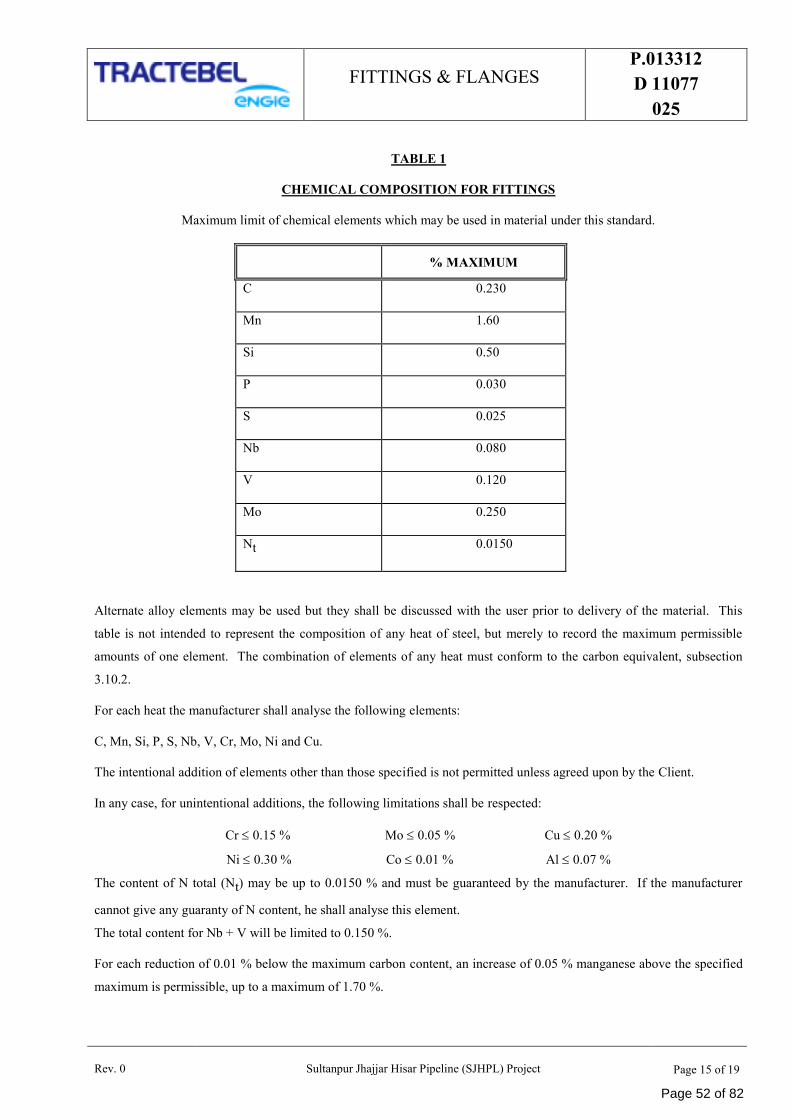
FITTINGS & FLANGES P.013312
D 11077
025
Rev. 0 Sultanpur Jhajjar Hisar Pipeline (SJHPL) Project Page 15 of 19
TABLE 1
CHEMICAL COMPOSITION FOR FITTINGS
Maximum limit of chemical elements which may be used in material under this standard.
% MAXIMUM
C 0.230
Mn 1.60
Si 0.50
P 0.030
S 0.025
Nb 0.080
V 0.120
Mo 0.250
Nt 0.0150
Alternate alloy elements may be used but they shall be discussed with the user prior to delivery of the material. This
table is not intended to represent the composition of any heat of steel, but merely to record the maximum permissible
amounts of one element. The combination of elements of any heat must conform to the carbon equivalent, subsection
3.10.2.
For each heat the manufacturer shall analyse the following elements:
C, Mn, Si, P, S, Nb, V, Cr, Mo, Ni and Cu.
The intentional addition of elements other than those specified is not permitted unless agreed upon by the Client.
In any case, for unintentional additions, the following limitations shall be respected:
Cr 0.15 % Mo 0.05 % Cu 0.20 %
Ni 0.30 % Co 0.01 % Al 0.07 %
The content of N total (Nt) may be up to 0.0150 % and must be guaranteed by the manufacturer. If the manufacturer
cannot give any guaranty of N content, he shall analyse this element.
The total content for Nb + V will be limited to 0.150 %.
For each reduction of 0.01 % below the maximum carbon content, an increase of 0.05 % manganese above the specified
maximum is permissible, up to a maximum of 1.70 %.
Page 52 of 82
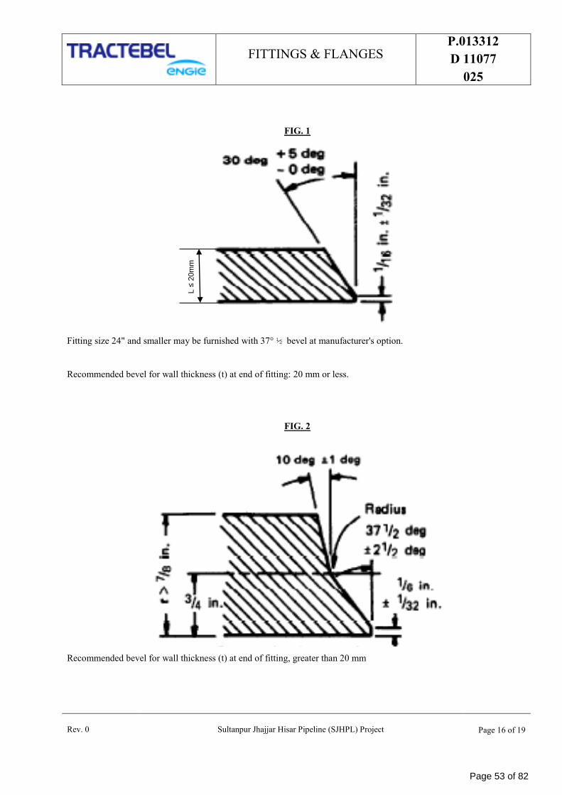
FITTINGS & FLANGES P.013312
D 11077
025
Rev. 0 Sultanpur Jhajjar Hisar Pipeline (SJHPL) Project Page 16 of 19
FIG. 1
Fitting size 24" and smaller may be furnished with 37° ½ bevel at manufacturer's option.
Recommended bevel for wall thickness (t) at end of fitting: 20 mm or less.
FIG. 2
Recommended bevel for wall thickness (t) at end of fitting, greater than 20 mm
L ≤
20m
m
Page 53 of 82
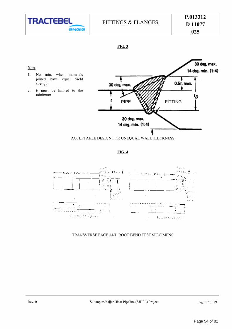
FITTINGS & FLANGES P.013312
D 11077
025
Rev. 0 Sultanpur Jhajjar Hisar Pipeline (SJHPL) Project Page 17 of 19
FIG. 3
Note
1. No min. when materials
joined have equal yield
strength.
2. t2 must be limited to the
minimum
ACCEPTABLE DESIGN FOR UNEQUAL WALL THICKNESS
FIG. 4
TRANSVERSE FACE AND ROOT BEND TEST SPECIMENS
PIPE FITTING
Page 54 of 82
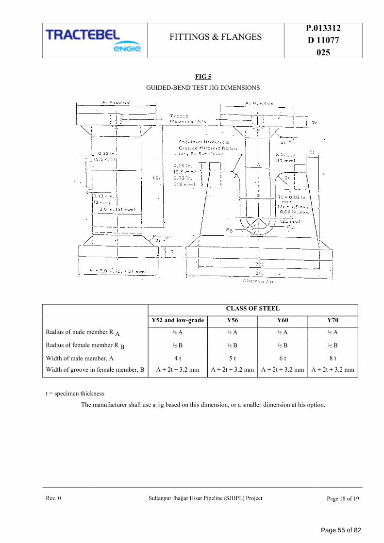
FITTINGS & FLANGES P.013312
D 11077
025
Rev. 0 Sultanpur Jhajjar Hisar Pipeline (SJHPL) Project Page 18 of 19
FIG 5
GUIDED-BEND TEST JIG DIMENSIONS
CLASS OF STEEL
Y52 and low-grade Y56 Y60 Y70
Radius of male member R A ½ A ½ A ½ A ½ A
Radius of female member R B ½ B ½ B ½ B ½ B
Width of male member, A 4 t 5 t 6 t 8 t
Width of groove in female member, B A + 2t + 3.2 mm A + 2t + 3.2 mm A + 2t + 3.2 mm A + 2t + 3.2 mm
t = specimen thickness
The manufacturer shall use a jig based on this dimension, or a smaller dimension at his option.
Page 55 of 82
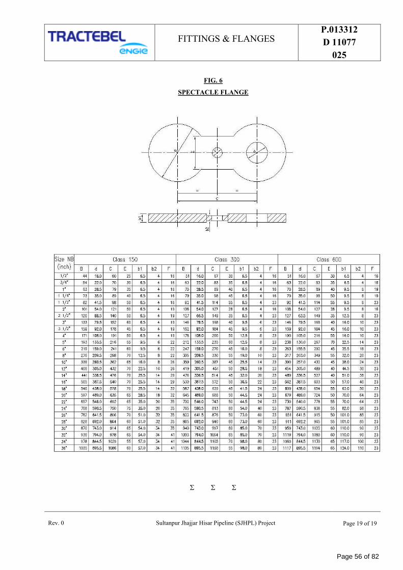
FITTINGS & FLANGES P.013312
D 11077
025
Rev. 0 Sultanpur Jhajjar Hisar Pipeline (SJHPL) Project Page 19 of 19
FIG. 6
SPECTACLE FLANGE
Page 56 of 82
PTS - PAINTING P.013312
D 11077
019
SULTANPUR JHAJJAR HISAR PIPELINE (SJHPL)
PROJECT
TRACTEBEL ENGINEERING PVT. LTD.
PTS - PAINTING
0 17.06.02019 Issued for Procurement SSA MS AR
Rev. Date Subject of Revision Prepared By Checked By Approved By
Page 57 of 82
PTS - PAINTING P.013312
D 11077
019
Rev. 0 Sultanpur Jhajjar Hisar Pipeline Project Page 1 of 1
TABLE OF CONTENTS
1.0 INTRODUCTION ................................................................................................................... 1
2.0 DEFINITIONS ....................................................................................................................... 1
3.0 COLOUR CODE SYSTEM ........................................................................................................ 1
Page 58 of 82
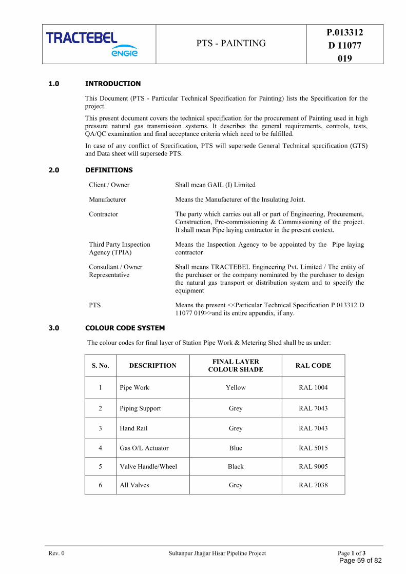
PTS - PAINTING P.013312
D 11077
019
Rev. 0 Sultanpur Jhajjar Hisar Pipeline Project Page 1 of 3
1.0 INTRODUCTION
This Document (PTS - Particular Technical Specification for Painting) lists the Specification for the
project.
This present document covers the technical specification for the procurement of Painting used in high
pressure natural gas transmission systems. It describes the general requirements, controls, tests,
QA/QC examination and final acceptance criteria which need to be fulfilled.
In case of any conflict of Specification, PTS will supersede General Technical specification (GTS)
and Data sheet will supersede PTS.
2.0 DEFINITIONS
Client / Owner Shall mean GAIL (I) Limited
Manufacturer Means the Manufacturer of the Insulating Joint.
Contractor The party which carries out all or part of Engineering, Procurement,
Construction, Pre-commissioning & Commissioning of the project.
It shall mean Pipe laying contractor in the present context.
Third Party Inspection
Agency (TPIA)
Means the Inspection Agency to be appointed by the Pipe laying
contractor
Consultant / Owner
Representative
Shall means TRACTEBEL Engineering Pvt. Limited / The entity of
the purchaser or the company nominated by the purchaser to design
the natural gas transport or distribution system and to specify the
equipment
PTS Means the present <<Particular Technical Specification P.013312 D
11077 019>>and its entire appendix, if any.
3.0 COLOUR CODE SYSTEM
The colour codes for final layer of Station Pipe Work & Metering Shed shall be as under:
S. No. DESCRIPTION FINAL LAYER
COLOUR SHADE RAL CODE
1 Pipe Work Yellow RAL 1004
2 Piping Support Grey RAL 7043
3 Hand Rail Grey RAL 7043
4 Gas O/L Actuator Blue RAL 5015
5 Valve Handle/Wheel Black RAL 9005
6 All Valves Grey RAL 7038
Page 59 of 82
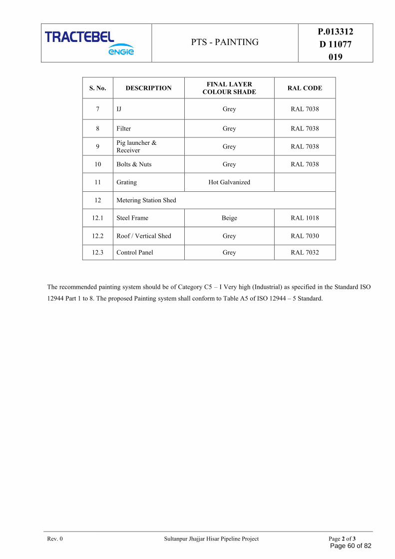
PTS - PAINTING P.013312
D 11077
019
Rev. 0 Sultanpur Jhajjar Hisar Pipeline Project Page 2 of 3
S. No. DESCRIPTION FINAL LAYER
COLOUR SHADE RAL CODE
7 IJ Grey RAL 7038
8 Filter Grey RAL 7038
9 Pig launcher &
Receiver Grey RAL 7038
10 Bolts & Nuts Grey RAL 7038
11 Grating Hot Galvanized
12 Metering Station Shed
12.1 Steel Frame Beige RAL 1018
12.2 Roof / Vertical Shed Grey RAL 7030
12.3 Control Panel Grey RAL 7032
The recommended painting system should be of Category C5 – I Very high (Industrial) as specified in the Standard ISO
12944 Part 1 to 8. The proposed Painting system shall conform to Table A5 of ISO 12944 – 5 Standard.
Page 60 of 82
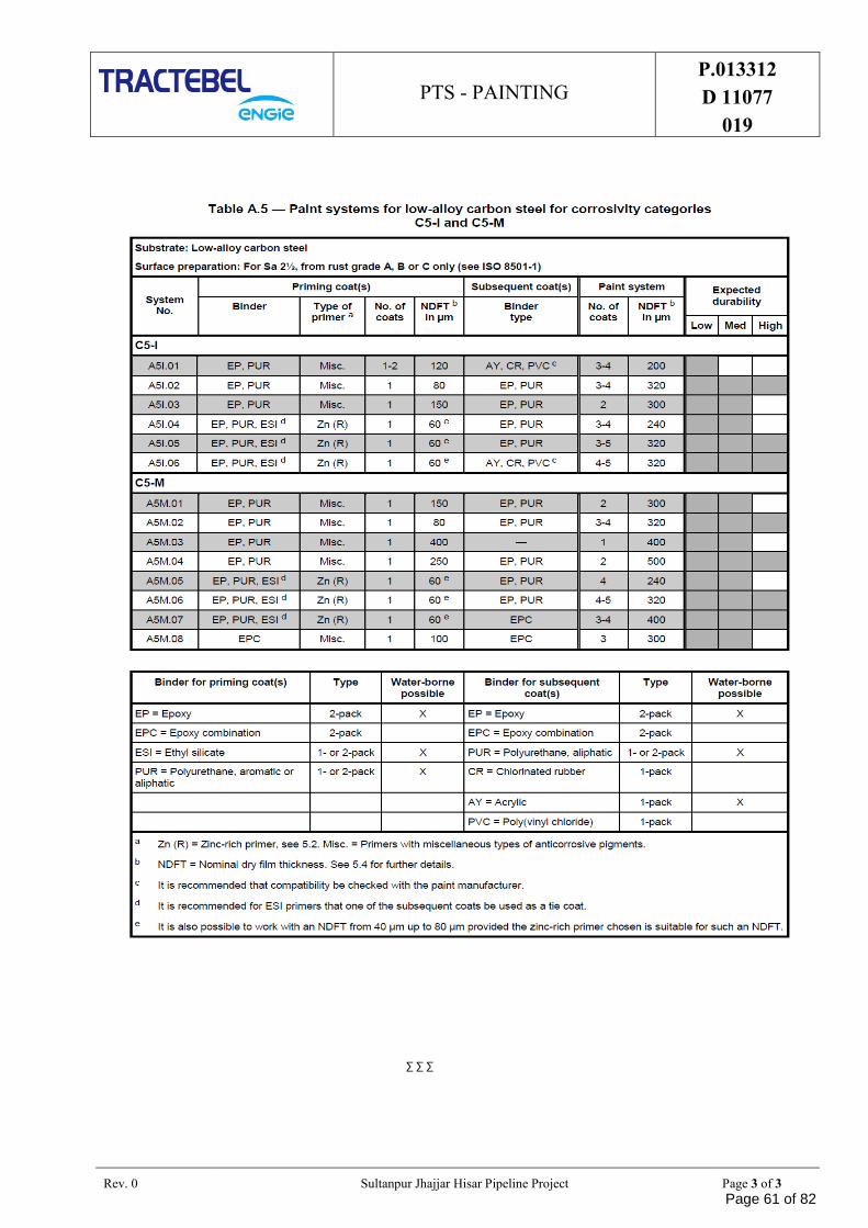
PTS - PAINTING P.013312
D 11077
019
Rev. 0 Sultanpur Jhajjar Hisar Pipeline Project Page 3 of 3
∑ ∑ ∑
Page 61 of 82
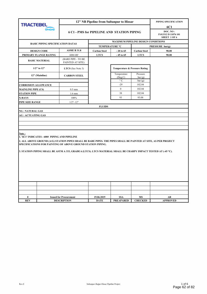
PIPING SPECIFICATION
6C1
DOC. NO :
P.013312 D 11076 101
SHEET 1 OF 6
ASME B 31.8 Carbon Steel - 20 to 65 Carbon Steel 98.00
600#-RF LTCS - 45 to 65 LTCS 98.00
(BARE PIPE - TO BE
PAINTED AT SITE)
LTCS (See Note 3)
CARBON STEELTemperature
(Deg.C)
Pressure
bar (g)
° C bar (g)
CORROSION ALLOWANCE -29 102.04
MAINLINE PIPE (CS) 0.5 mm 0 102.04
1.6 mm 38 102.04
100% 93 93.08
PIPE SIZE RANGE 1/2"- 12"
0 19.06.2019 SSA MS AR
REV DATE PREAPARED CHECKED APPROVED
12" NB Pipeline from Sultanpur to Hissar
PRESSURE bar(g)
FLUIDS
1/2" to 12"
12" (Mainline)
NG : NATURAL GAS
DESCRIPTION
Issued for Procurement
2. ALL ABOVE GROUND (A/G) STATION PIPES SHALL BE BARE PIPES. THE PIPES SHALL BE PAINTED AT SITE, AS PER PROJECT
SPECIFICATIONS FOR PAINTING OF ABOVE GROUND STATION PIPING.
BASIC PIPING SPECIFICATION DATASTEMPERATURE °C
6 C1 - PMS for PIPELINE AND STATION PIPING
Temperature & Pressure Rating
STATION PIPE
DESIGN CODE
MAXIMUM PIPELINE DESIGN CONDITIONS
3. STATION PIPING SHALL BE ASTM A 333, GRADE 6 (LTCS). LTCS MATERIAL SHALL BE CHARPY IMPACT TESTED AT (-45 °C).
X-RAYS
BASIC MATERIAL
PRIMARY FLANGE RATING
Note :
1. '6C1' INDICATES - 600# PIPING AND PIPELINE
AG : ACTUATING GAS
Rev.0 Sultanpur-Jhajjar-Hissar Pipeline Project 1 of 6
Page 62 of 82
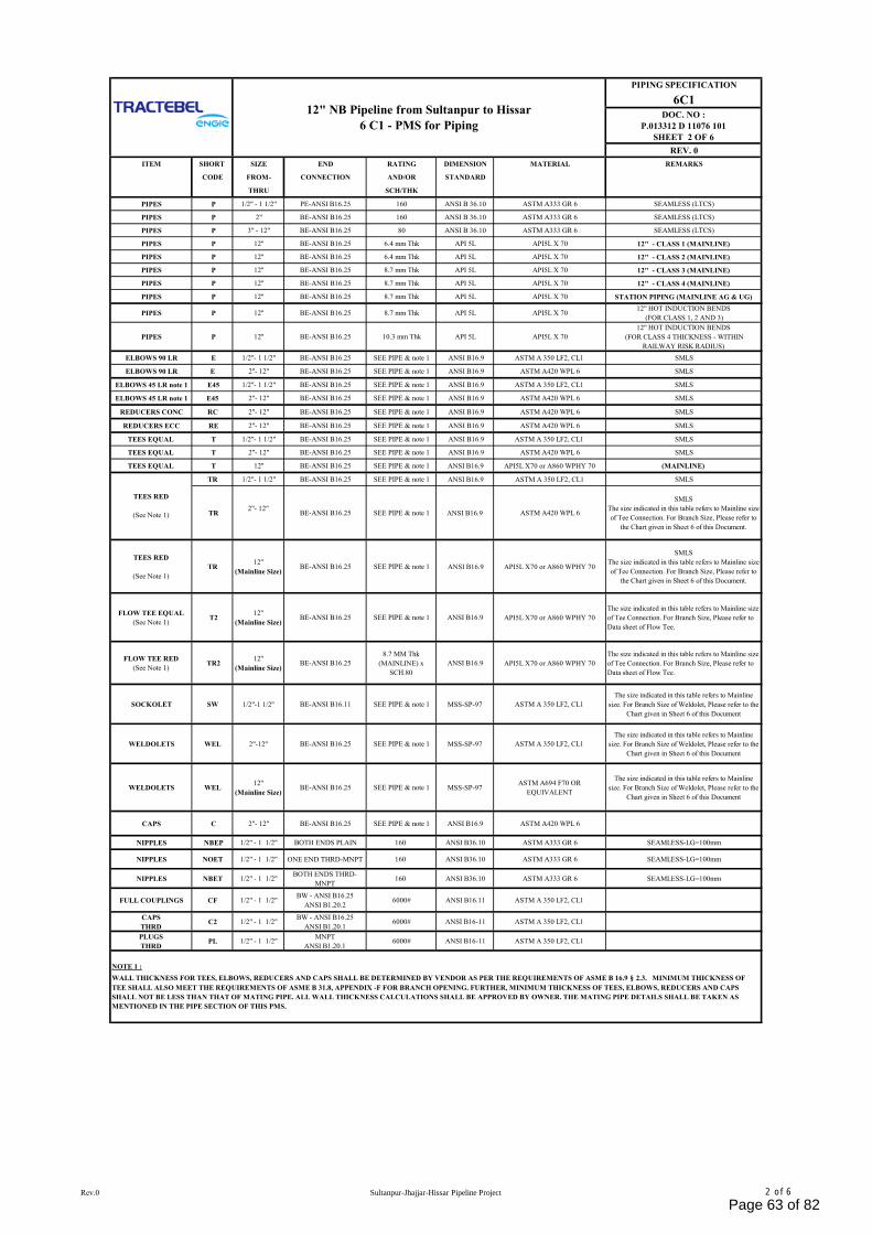
PIPING SPECIFICATION
6C1DOC. NO :
P.013312 D 11076 101
SHEET 2 OF 6
REV. 0
ITEM SHORT SIZE END RATING DIMENSION MATERIAL REMARKS
CODE FROM- CONNECTION AND/OR STANDARD
THRU SCH/THK
PIPES P 1/2" - 1 1/2" PE-ANSI B16.25 160 ANSI B 36.10 ASTM A333 GR 6 SEAMLESS (LTCS)
PIPES P 2" BE-ANSI B16.25 160 ANSI B 36.10 ASTM A333 GR 6 SEAMLESS (LTCS)
PIPES P 3" - 12" BE-ANSI B16.25 80 ANSI B 36.10 ASTM A333 GR 6 SEAMLESS (LTCS)
PIPES P 12'' BE-ANSI B16.25 6.4 mm Thk API 5L API5L X 70 12" - CLASS 1 (MAINLINE)
PIPES P 12'' BE-ANSI B16.25 6.4 mm Thk API 5L API5L X 70 12" - CLASS 2 (MAINLINE)
PIPES P 12'' BE-ANSI B16.25 8.7 mm Thk API 5L API5L X 70 12" - CLASS 3 (MAINLINE)
PIPES P 12'' BE-ANSI B16.25 8.7 mm Thk API 5L API5L X 70 12" - CLASS 4 (MAINLINE)
PIPES P 12'' BE-ANSI B16.25 8.7 mm Thk API 5L API5L X 70 STATION PIPING (MAINLINE AG & UG)
PIPES P 12'' BE-ANSI B16.25 8.7 mm Thk API 5L API5L X 7012" HOT INDUCTION BENDS
(FOR CLASS 1, 2 AND 3)
PIPES P 12'' BE-ANSI B16.25 10.3 mm Thk API 5L API5L X 70
12" HOT INDUCTION BENDS
(FOR CLASS 4 THICKNESS - WITHIN
RAILWAY RISK RADIUS)
ELBOWS 90 LR E 1/2"- 1 1/2" BE-ANSI B16.25 SEE PIPE & note 1 ANSI B16.9 ASTM A 350 LF2, CL1 SMLS
ELBOWS 90 LR E 2"- 12" BE-ANSI B16.25 SEE PIPE & note 1 ANSI B16.9 ASTM A420 WPL 6 SMLS
ELBOWS 45 LR note 1 E45 1/2"- 1 1/2" BE-ANSI B16.25 SEE PIPE & note 1 ANSI B16.9 ASTM A 350 LF2, CL1 SMLS
ELBOWS 45 LR note 1 E45 2"- 12" BE-ANSI B16.25 SEE PIPE & note 1 ANSI B16.9 ASTM A420 WPL 6 SMLS
REDUCERS CONC RC 2"- 12" BE-ANSI B16.25 SEE PIPE & note 1 ANSI B16.9 ASTM A420 WPL 6 SMLS
REDUCERS ECC RE 2"- 12" BE-ANSI B16.25 SEE PIPE & note 1 ANSI B16.9 ASTM A420 WPL 6 SMLS
TEES EQUAL T 1/2"- 1 1/2" BE-ANSI B16.25 SEE PIPE & note 1 ANSI B16.9 ASTM A 350 LF2, CL1 SMLS
TEES EQUAL T 2"- 12" BE-ANSI B16.25 SEE PIPE & note 1 ANSI B16.9 ASTM A420 WPL 6 SMLS
TEES EQUAL T 12'' BE-ANSI B16.25 SEE PIPE & note 1 ANSI B16.9 API5L X70 or A860 WPHY 70 (MAINLINE)
TR 1/2"- 1 1/2" BE-ANSI B16.25 SEE PIPE & note 1 ANSI B16.9 ASTM A 350 LF2, CL1 SMLS
TR2"- 12"
BE-ANSI B16.25 SEE PIPE & note 1 ANSI B16.9 ASTM A420 WPL 6
SMLS
The size indicated in this table refers to Mainline size
of Tee Connection. For Branch Size, Please refer to
the Chart given in Sheet 6 of this Document.
TEES RED
(See Note 1)
TR12''
(Mainline Size)BE-ANSI B16.25 SEE PIPE & note 1 ANSI B16.9 API5L X70 or A860 WPHY 70
SMLS
The size indicated in this table refers to Mainline size
of Tee Connection. For Branch Size, Please refer to
the Chart given in Sheet 6 of this Document.
FLOW TEE EQUAL
(See Note 1) T2
12''
(Mainline Size)BE-ANSI B16.25 SEE PIPE & note 1 ANSI B16.9 API5L X70 or A860 WPHY 70
The size indicated in this table refers to Mainline size
of Tee Connection. For Branch Size, Please refer to
Data sheet of Flow Tee.
FLOW TEE RED
(See Note 1) TR2
12''
(Mainline Size)BE-ANSI B16.25
8.7 MM Thk
(MAINLINE) x
SCH.80
ANSI B16.9 API5L X70 or A860 WPHY 70
The size indicated in this table refers to Mainline size
of Tee Connection. For Branch Size, Please refer to
Data sheet of Flow Tee.
SOCKOLET SW 1/2"-1 1/2'' BE-ANSI B16.11 SEE PIPE & note 1 MSS-SP-97 ASTM A 350 LF2, CL1
The size indicated in this table refers to Mainline
size. For Branch Size of Weldolet, Please refer to the
Chart given in Sheet 6 of this Document
WELDOLETS WEL 2"-12'' BE-ANSI B16.25 SEE PIPE & note 1 MSS-SP-97 ASTM A 350 LF2, CL1
The size indicated in this table refers to Mainline
size. For Branch Size of Weldolet, Please refer to the
Chart given in Sheet 6 of this Document
WELDOLETS WEL12''
(Mainline Size)BE-ANSI B16.25 SEE PIPE & note 1 MSS-SP-97
ASTM A694 F70 OR
EQUIVALENT
The size indicated in this table refers to Mainline
size. For Branch Size of Weldolet, Please refer to the
Chart given in Sheet 6 of this Document
CAPS C 2"- 12" BE-ANSI B16.25 SEE PIPE & note 1 ANSI B16.9 ASTM A420 WPL 6
NIPPLES NBEP 1/2" - 1 1/2" BOTH ENDS PLAIN 160 ANSI B36.10 ASTM A333 GR 6 SEAMLESS-LG=100mm
NIPPLES NOET 1/2" - 1 1/2" ONE END THRD-MNPT 160 ANSI B36.10 ASTM A333 GR 6 SEAMLESS-LG=100mm
NIPPLES NBET 1/2" - 1 1/2"BOTH ENDS THRD-
MNPT160 ANSI B36.10 ASTM A333 GR 6 SEAMLESS-LG=100mm
FULL COUPLINGS CF 1/2" - 1 1/2"BW - ANSI B16.25
ANSI B1.20.26000# ANSI B16.11 ASTM A 350 LF2, CL1
CAPS
THRDC2 1/2" - 1 1/2"
BW - ANSI B16.25
ANSI B1.20.16000# ANSI B16-11 ASTM A 350 LF2, CL1
PLUGS
THRDPL 1/2" - 1 1/2"
MNPT
ANSI B1.20.16000# ANSI B16-11 ASTM A 350 LF2, CL1
12" NB Pipeline from Sultanpur to Hissar
6 C1 - PMS for Piping
NOTE 1 :
WALL THICKNESS FOR TEES, ELBOWS, REDUCERS AND CAPS SHALL BE DETERMINED BY VENDOR AS PER THE REQUIREMENTS OF ASME B 16.9 § 2.3. MINIMUM THICKNESS OF
TEE SHALL ALSO MEET THE REQUIREMENTS OF ASME B 31.8, APPENDIX -F FOR BRANCH OPENING. FURTHER, MINIMUM THICKNESS OF TEES, ELBOWS, REDUCERS AND CAPS
SHALL NOT BE LESS THAN THAT OF MATING PIPE. ALL WALL THICKNESS CALCULATIONS SHALL BE APPROVED BY OWNER. THE MATING PIPE DETAILS SHALL BE TAKEN AS
MENTIONED IN THE PIPE SECTION OF THIS PMS.
TEES RED
(See Note 1)
Rev.0 Sultanpur-Jhajjar-Hissar Pipeline Project 2 of 6
Page 63 of 82
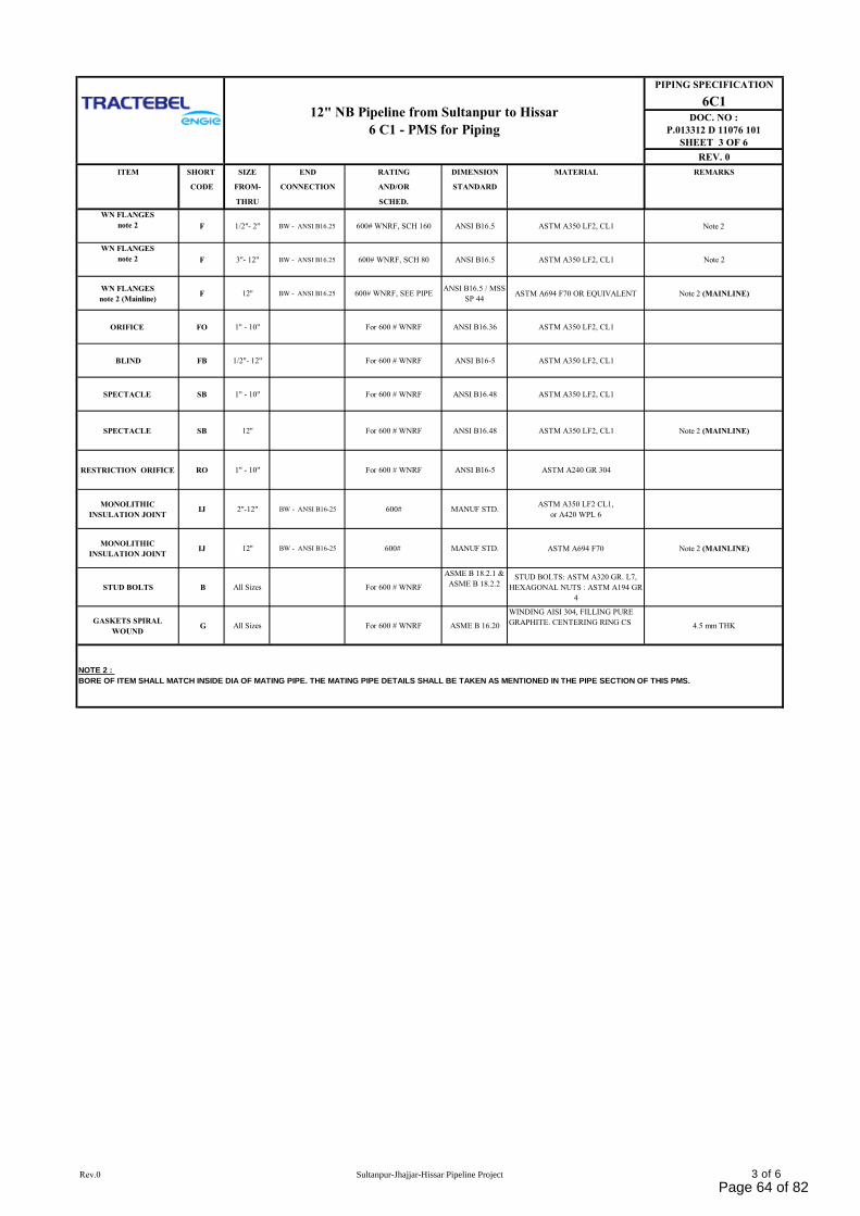
PIPING SPECIFICATION
6C1DOC. NO :
P.013312 D 11076 101
SHEET 3 OF 6
REV. 0
ITEM SHORT SIZE END RATING DIMENSION MATERIAL REMARKS
CODE FROM- CONNECTION AND/OR STANDARD
THRU SCHED.
WN FLANGES
note 2 F 1/2"- 2" BW - ANSI B16.25 600# WNRF, SCH 160 ANSI B16.5 ASTM A350 LF2, CL1 Note 2
WN FLANGES
note 2 F 3"- 12" BW - ANSI B16.25 600# WNRF, SCH 80 ANSI B16.5 ASTM A350 LF2, CL1 Note 2
WN FLANGES
note 2 (Mainline)F 12'' BW - ANSI B16.25 600# WNRF, SEE PIPE
ANSI B16.5 / MSS
SP 44ASTM A694 F70 OR EQUIVALENT Note 2 (MAINLINE)
ORIFICE FO 1" - 10" For 600 # WNRF ANSI B16.36 ASTM A350 LF2, CL1
BLIND FB 1/2"- 12" For 600 # WNRF ANSI B16-5 ASTM A350 LF2, CL1
SPECTACLE SB 1" - 10" For 600 # WNRF ANSI B16.48 ASTM A350 LF2, CL1
SPECTACLE SB 12'' For 600 # WNRF ANSI B16.48 ASTM A350 LF2, CL1 Note 2 (MAINLINE)
RESTRICTION ORIFICE RO 1" - 10" For 600 # WNRF ANSI B16-5 ASTM A240 GR 304
MONOLITHIC
INSULATION JOINTIJ 2"-12" BW - ANSI B16-25 600# MANUF STD.
ASTM A350 LF2 CL1,
or A420 WPL 6
MONOLITHIC
INSULATION JOINTIJ 12'' BW - ANSI B16-25 600# MANUF STD. ASTM A694 F70 Note 2 (MAINLINE)
STUD BOLTS B All Sizes For 600 # WNRF
ASME B 18.2.1 &
ASME B 18.2.2STUD BOLTS: ASTM A320 GR. L7,
HEXAGONAL NUTS : ASTM A194 GR
4
GASKETS SPIRAL
WOUND G All Sizes For 600 # WNRF ASME B 16.20
WINDING AISI 304, FILLING PURE
GRAPHITE. CENTERING RING CS 4.5 mm THK
NOTE 2 :
BORE OF ITEM SHALL MATCH INSIDE DIA OF MATING PIPE. THE MATING PIPE DETAILS SHALL BE TAKEN AS MENTIONED IN THE PIPE SECTION OF THIS PMS.
12" NB Pipeline from Sultanpur to Hissar
6 C1 - PMS for Piping
Rev.0 Sultanpur-Jhajjar-Hissar Pipeline Project 3 of 6
Page 64 of 82
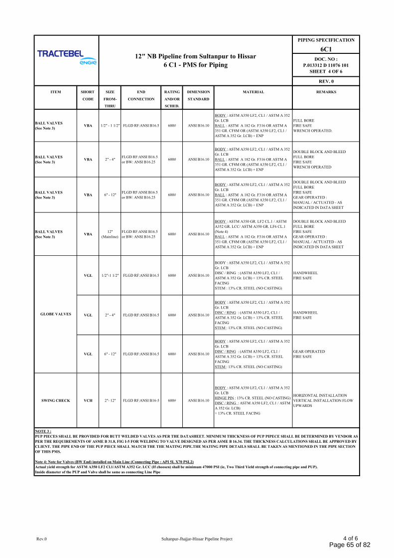
PIPING SPECIFICATION
6C1
DOC. NO :
P.013312 D 11076 101
SHEET 4 OF 6
REV. 0
ITEM SHORT SIZE END RATING DIMENSION MATERIAL REMARKS
CODE FROM- CONNECTION AND/OR STANDARD
THRU SCHED.
BALL VALVES
(See Note 3)VBA 1/2" - 1 1/2" FLGD RF:ANSI B16.5 600# ANSI B16.10
BODY : ASTM A350 LF2, CL1 / ASTM A 352
Gr. LCB
BALL : ASTM A 182 Gr. F316 OR ASTM A
351 GR. CF8M OR (ASTM A350 LF2, CL1 /
ASTM A 352 Gr. LCB) + ENP
FULL BORE
FIRE SAFE
WRENCH OPERATED.
BALL VALVES
(See Note 3)VBA 2" - 4"
FLGD RF:ANSI B16.5
or BW: ANSI B16.25600# ANSI B16.10
BODY : ASTM A350 LF2, CL1 / ASTM A 352
Gr. LCB
BALL : ASTM A 182 Gr. F316 OR ASTM A
351 GR. CF8M OR (ASTM A350 LF2, CL1 /
ASTM A 352 Gr. LCB) + ENP
DOUBLE BLOCK AND BLEED
FULL BORE
FIRE SAFE
WRENCH OPERATED
BALL VALVES
(See Note 3)VBA 6" - 12''
FLGD RF:ANSI B16.5
or BW: ANSI B16.25600# ANSI B16.10
BODY : ASTM A350 LF2, CL1 / ASTM A 352
Gr. LCB
BALL : ASTM A 182 Gr. F316 OR ASTM A
351 GR. CF8M OR (ASTM A350 LF2, CL1 /
ASTM A 352 Gr. LCB) + ENP
DOUBLE BLOCK AND BLEED
FULL BORE
FIRE SAFE
GEAR OPERATED :
MANUAL / ACTUATED - AS
INDICATED IN DATA SHEET
BALL VALVES
(See Note 3)VBA
12''
(Mainline)
FLGD RF:ANSI B16.5
or BW: ANSI B16.25600# ANSI B16.10
BODY : ASTM A350 GR. LF2 CL.1 / ASTM
A352 GR. LCC/ ASTM A350 GR. LF6 CL.1
(Note 4)
BALL : ASTM A 182 Gr. F316 OR ASTM A
351 GR. CF8M OR (ASTM A350 LF2, CL1 /
ASTM A 352 Gr. LCB) + ENP
DOUBLE BLOCK AND BLEED
FULL BORE
FIRE SAFE
GEAR OPERATED :
MANUAL / ACTUATED - AS
INDICATED IN DATA SHEET
VGL 1/2"-1 1/2" FLGD RF:ANSI B16.5 600# ANSI B16.10
BODY : ASTM A350 LF2, CL1 / ASTM A 352
Gr. LCB
DISC / RING : (ASTM A350 LF2, CL1 /
ASTM A 352 Gr. LCB) + 13% CR. STEEL
FACING
STEM : 13% CR. STEEL (NO CASTING)
HANDWHEEL
FIRE SAFE
VGL 2" - 4" FLGD RF:ANSI B16.5 600# ANSI B16.10
BODY : ASTM A350 LF2, CL1 / ASTM A 352
Gr. LCB
DISC / RING : (ASTM A350 LF2, CL1 /
ASTM A 352 Gr. LCB) + 13% CR. STEEL
FACING
STEM : 13% CR. STEEL (NO CASTING)
HANDWHEEL
FIRE SAFE
VGL 6" - 12'' FLGD RF:ANSI B16.5 600# ANSI B16.10
BODY : ASTM A350 LF2, CL1 / ASTM A 352
Gr. LCB
DISC / RING : (ASTM A350 LF2, CL1 /
ASTM A 352 Gr. LCB) + 13% CR. STEEL
FACING
STEM : 13% CR. STEEL (NO CASTING)
GEAR OPERATED
FIRE SAFE
SWING CHECK VCH 2"- 12'' FLGD RF:ANSI B16-5 600# ANSI B16.10
BODY : ASTM A350 LF2, CL1 / ASTM A 352
Gr. LCB
HINGE PIN : 13% CR. STEEL (NO CASTING)
DISC / RING : ASTM A350 LF2, CL1 / ASTM
A 352 Gr. LCB)
+ 13% CR. STEEL FACING
HORIZONTAL INSTALLATION
VERTICAL INSTALLATION FLOW
UPWARDS
NOTE 3 :
PUP PIECES SHALL BE PROVIDED FOR BUTT WELDED VALVES AS PER THE DATASHEET. MINIMUM THICKNESS OF PUP PIPECE SHALL BE DETERMINED BY VENDOR AS
PER THE REQUIREMENTS OF ASME B 31.8, FIG I-5 FOR WELDING TO VALVE DESIGNED AS PER ASME B 16.34. THE THICKNESS CALCULATIONS SHALL BE APPROVED BY
CLIENT. THE PIPE END OF THE PUP PIECE SHALL MATCH THE THE MATING PIPE.THE MATING PIPE DETAILS SHALL BE TAKEN AS MENTIONED IN THE PIPE SECTION
OF THIS PMS.
Note 4: Note for Valves (BW End) installed on Main Line (Connecting Pipe : API 5L X70 PSL2)
Actual yield strength for ASTM A350 LF2 Cl.1/ASTM A352 Gr. LCC (If choosen) shall be minimum 47000 PSI (ie, Two Third Yield strength of connecting pipe and PUP).
Inside diameter of the PUP and Valve shall be same as connecting Line Pipe
12" NB Pipeline from Sultanpur to Hissar
6 C1 - PMS for Piping
GLOBE VALVES
Rev.0 Sultanpur-Jhajjar-Hissar Pipeline Project 4 of 6Page 65 of 82
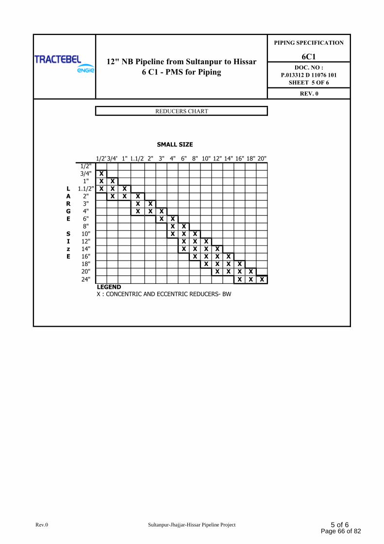
PIPING SPECIFICATION
6C1
DOC. NO :
P.013312 D 11076 101
SHEET 5 OF 6
REV. 0
SMALL SIZE
1/2"3/4" 1" 1.1/2" 2" 3" 4" 6" 8" 10" 12" 14" 16" 18" 20"
1/2"
3/4" X
1" X X
L 1.1/2" X X X
A 2" X X X
R 3" X X
G 4" X X X
E 6" X X
8" X X
S 10" X X X
I 12" X X X
z 14" X X X X
E 16" X X X X
18" X X X X
20" X X X X
24" X X X
LEGENDX : CONCENTRIC AND ECCENTRIC REDUCERS- BW
REDUCERS CHART
12" NB Pipeline from Sultanpur to Hissar
6 C1 - PMS for Piping
Rev.0 Sultanpur-Jhajjar-Hissar Pipeline Project 5 of 6Page 66 of 82
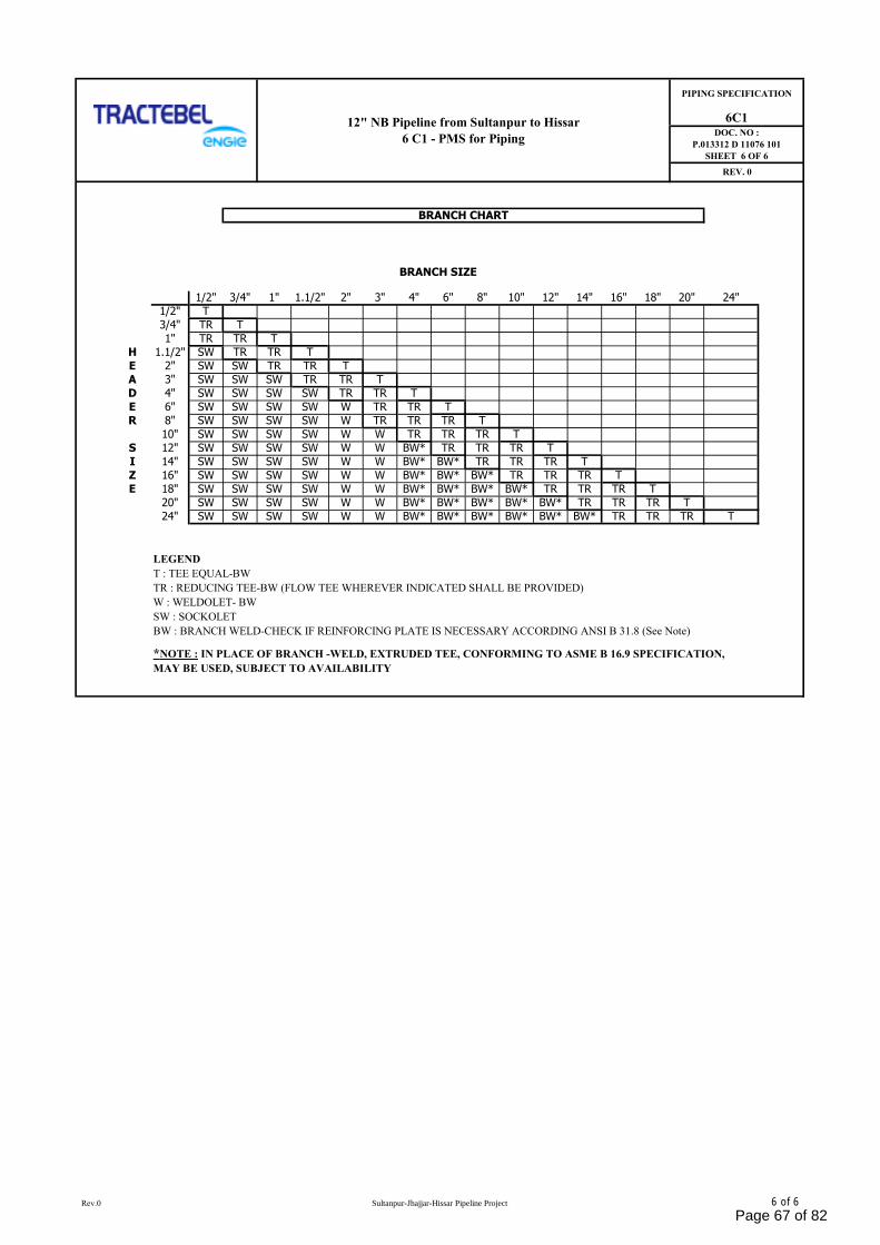
BRANCH SIZE
1/2" 3/4" 1" 1.1/2" 2" 3" 4" 6" 8" 10" 12" 14" 16" 18" 20" 24"
1/2" T
3/4" TR T
1" TR TR T
H 1.1/2" SW TR TR T
E 2" SW SW TR TR T
A 3" SW SW SW TR TR T
D 4" SW SW SW SW TR TR T
E 6" SW SW SW SW W TR TR T
R 8" SW SW SW SW W TR TR TR T
10" SW SW SW SW W W TR TR TR T
S 12" SW SW SW SW W W BW* TR TR TR T
I 14" SW SW SW SW W W BW* BW* TR TR TR T
Z 16" SW SW SW SW W W BW* BW* BW* TR TR TR T
E 18" SW SW SW SW W W BW* BW* BW* BW* TR TR TR T
20" SW SW SW SW W W BW* BW* BW* BW* BW* TR TR TR T
24" SW SW SW SW W W BW* BW* BW* BW* BW* BW* TR TR TR T
LEGEND
T : TEE EQUAL-BW
TR : REDUCING TEE-BW (FLOW TEE WHEREVER INDICATED SHALL BE PROVIDED)
W : WELDOLET- BW
SW : SOCKOLET
BW : BRANCH WELD-CHECK IF REINFORCING PLATE IS NECESSARY ACCORDING ANSI B 31.8 (See Note)
6C1DOC. NO :
P.013312 D 11076 101
SHEET 6 OF 6
REV. 0
BRANCH CHART
*NOTE : IN PLACE OF BRANCH -WELD, EXTRUDED TEE, CONFORMING TO ASME B 16.9 SPECIFICATION,
MAY BE USED, SUBJECT TO AVAILABILITY
12" NB Pipeline from Sultanpur to Hissar
6 C1 - PMS for Piping
PIPING SPECIFICATION
Rev.0 Sultanpur-Jhajjar-Hissar Pipeline Project 6 of 6
Page 67 of 82
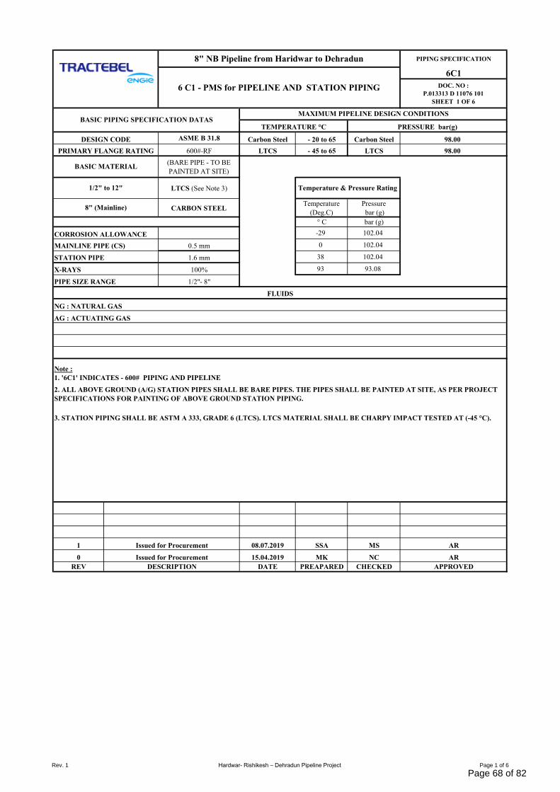
PIPING SPECIFICATION
6C1
DOC. NO :
P.013313 D 11076 101
SHEET 1 OF 6
ASME B 31.8 Carbon Steel - 20 to 65 Carbon Steel 98.00
600#-RF LTCS - 45 to 65 LTCS 98.00
(BARE PIPE - TO BE
PAINTED AT SITE)
LTCS (See Note 3)
CARBON STEELTemperature
(Deg.C)
Pressure
bar (g)
° C bar (g)
CORROSION ALLOWANCE -29 102.04
MAINLINE PIPE (CS) 0.5 mm 0 102.04
1.6 mm 38 102.04
100% 93 93.08
PIPE SIZE RANGE 1/2"- 8"
1 08.07.2019 SSA MS AR
0 15.04.2019 MK NC AR
REV DATE PREAPARED CHECKED APPROVED
8" NB Pipeline from Haridwar to Dehradun
PRESSURE bar(g)
FLUIDS
1/2" to 12"
8" (Mainline)
NG : NATURAL GAS
DESCRIPTION
Issued for Procurement
Issued for Procurement
2. ALL ABOVE GROUND (A/G) STATION PIPES SHALL BE BARE PIPES. THE PIPES SHALL BE PAINTED AT SITE, AS PER PROJECT
SPECIFICATIONS FOR PAINTING OF ABOVE GROUND STATION PIPING.
BASIC PIPING SPECIFICATION DATASTEMPERATURE °C
6 C1 - PMS for PIPELINE AND STATION PIPING
Temperature & Pressure Rating
STATION PIPE
DESIGN CODE
MAXIMUM PIPELINE DESIGN CONDITIONS
3. STATION PIPING SHALL BE ASTM A 333, GRADE 6 (LTCS). LTCS MATERIAL SHALL BE CHARPY IMPACT TESTED AT (-45 °C).
X-RAYS
BASIC MATERIAL
PRIMARY FLANGE RATING
Note :
1. '6C1' INDICATES - 600# PIPING AND PIPELINE
AG : ACTUATING GAS
Rev. 1 Hardwar- Rishikesh – Dehradun Pipeline Project Page 1 of 6
Page 68 of 82
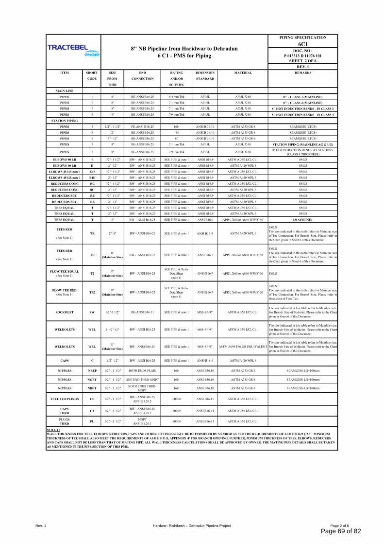
PIPING SPECIFICATION
6C1DOC. NO :
P.013313 D 11076 101
SHEET 2 OF 6
REV. 0
ITEM SHORT SIZE END RATING DIMENSION MATERIAL REMARKS
CODE FROM- CONNECTION AND/OR STANDARD
THRU SCH/THK
MAIN LINE
PIPES P 8'' BE-ANSI B16.25 6.4 mm Thk API 5L API5L X 60 8" - CLASS 3 (MAINLINE)
PIPES P 8'' BE-ANSI B16.25 7.1 mm Thk API 5L API5L X 60 8" - CLASS 4 (MAINLINE)
PIPES P 8'' BE-ANSI B16.25 7.1 mm Thk API 5L API5L X 60 8" HOT INDUCTION BENDS - IN CLASS 3
PIPES P 8'' BE-ANSI B16.25 7.9 mm Thk API 5L API5L X 60 8" HOT INDUCTION BENDS - IN CLASS 4
STATION PIPING
PIPES P 1/2" - 1 1/2" PE-ANSI B16-25 160 ANSI B 36.10 ASTM A333 GR 6 SEAMLESS (LTCS)
PIPES P 2" BE-ANSI B16.25 160 ANSI B 36.10 ASTM A333 GR 6 SEAMLESS (LTCS)
PIPES P 3" - 12" BE-ANSI B16.25 80 ANSI B 36.10 ASTM A333 GR 6 SEAMLESS (LTCS)
PIPES P 8'' BE-ANSI B16.25 7.1 mm Thk API 5L API5L X 60 STATION PIPING (MAINLINE AG & UG)
PIPES P 8'' BE-ANSI B16.25 7.9 mm Thk API 5L API5L X 608" HOT INDUCTION BENDS AT STATIONS
(CLASS 4 THICKNESS)
ELBOWS 90 LR E 1/2"- 1 1/2" BW - ANSI B16.25 SEE PIPE & note 1 ANSI B16.9 ASTM A 350 LF2, CL1 SMLS
ELBOWS 90 LR E 2"- 12" BW - ANSI B16.25 SEE PIPE & note 1 ANSI B16.9 ASTM A420 WPL 6 SMLS
ELBOWS 45 LR note 1 E45 1/2"- 1 1/2" BW - ANSI B16.25 SEE PIPE & note 1 ANSI B16.9 ASTM A 350 LF2, CL1 SMLS
ELBOWS 45 LR note 1 E45 2"- 12" BW - ANSI B16.25 SEE PIPE & note 1 ANSI B16.9 ASTM A420 WPL 6 SMLS
REDUCERS CONC RC 1/2"- 1 1/2" BW - ANSI B16.25 SEE PIPE & note 1 ANSI B16.9 ASTM A 350 LF2, CL1 SMLS
REDUCERS CONC RC 2"- 12" BW - ANSI B16.25 SEE PIPE & note 1 ANSI B16.9 ASTM A420 WPL 6 SMLS
REDUCERS ECC RE 1/2"- 1 1/2" BW - ANSI B16.25 SEE PIPE & note 1 ANSI B16.9 ASTM A 350 LF2, CL1 SMLS
REDUCERS ECC RE 2"- 12" BW - ANSI B16.25 SEE PIPE & note 1 ANSI B16.9 ASTM A420 WPL 6 SMLS
TEES EQUAL T 1/2"- 1 1/2" BW - ANSI B16.25 SEE PIPE & note 1 ANSI B16.9 ASTM A 350 LF2, CL1 SMLS
TEES EQUAL T 2"- 12" BW - ANSI B16.25 SEE PIPE & note 1 ANSI B16.9 ASTM A420 WPL 6 SMLS
TEES EQUAL T 8'' BW - ANSI B16.25 SEE PIPE & note 1 ANSI B16.9 API5L X60 or A860 WPHY 60 (MAINLINE)
TEES RED
(See Note 1)
TR 2"- 8" BW - ANSI B16-25 SEE PIPE & note 1 ANSI B16-9 ASTM A420 WPL 6
SMLS
The size indicated in this table refers to Mainline size
of Tee Connection. For Branch Size, Please refer to
the Chart given in Sheet 6 of this Document.
TEES RED
(See Note 1)
TR8''
(Mainline Size)BW - ANSI B16.25 SEE PIPE & note 1 ANSI B16.9 API5L X60 or A860 WPHY 60
SMLS
The size indicated in this table refers to Mainline size
of Tee Connection. For Branch Size, Please refer to
the Chart given in Sheet 6 of this Document.
FLOW TEE EQUAL
(See Note 1) T2
8''
(Mainline Size)BW - ANSI B16-25
SEE PIPE & Refer
Data Sheet
(note 1)
ANSI B16.9 API5L X60 or A860 WPHY 60 SMLS
FLOW TEE RED
(See Note 1) TR2
8''
(Mainline Size)BW - ANSI B16-25
SEE PIPE & Refer
Data Sheet
(note 1)
ANSI B16.9 API5L X60 or A860 WPHY 60
SMLS
The size indicated in this table refers to Mainline size
of Tee Connection. For Branch Size, Please refer to
Data sheet of Flow Tee.
SOCKOLET SW 1/2"-1 1/2'' BE-ANSI B16.11 SEE PIPE & note 1 MSS-SP-97 ASTM A 350 LF2, CL1
The size indicated in this table refers to Mainline size.
For Branch Size of Sockolet, Please refer to the Chart
given in Sheet 6 of this Document
WELDOLETS WEL 1 1/2"-12'' BW - ANSI B16.25 SEE PIPE & note 1 MSS-SP-97 ASTM A 350 LF2, CL1
The size indicated in this table refers to Mainline size.
For Branch Size of Weldolet, Please refer to the Chart
given in Sheet 6 of this Document
WELDOLETS WEL8''
(Mainline Size)BW - ANSI B16.25 SEE PIPE & note 1 MSS-SP-97 ASTM A694 F60 OR EQUIVALENT
The size indicated in this table refers to Mainline size.
For Branch Size of Weldolet, Please refer to the Chart
given in Sheet 6 of this Document
CAPS C 1/2"- 12" BW - ANSI B16.25 SEE PIPE & note 1 ANSI B16-9 ASTM A420 WPL 6
NIPPLES NBEP 1/2" - 1 1/2" BOTH ENDS PLAIN 160 ANSI B36.10 ASTM A333 GR 6 SEAMLESS-LG=100mm
NIPPLES NOET 1/2" - 1 1/2" ONE END THRD-MNPT 160 ANSI B36.10 ASTM A333 GR 6 SEAMLESS-LG=100mm
NIPPLES NBET 1/2" - 1 1/2"BOTH ENDS THRD-
MNPT160 ANSI B36.10 ASTM A333 GR 6 SEAMLESS-LG=100mm
FULL COUPLINGS CF 1/2" - 1 1/2"BW - ANSI B16.25
ANSI B1.20.26000# ANSI B16.11 ASTM A 350 LF2, CL1
CAPS
THRDC2 1/2" - 1 1/2"
BW - ANSI B16.25
ANSI B1.20.16000# ANSI B16-11 ASTM A 350 LF2, CL1
PLUGS
THRDPL 1/2" - 1 1/2"
MNPT
ANSI B1.20.16000# ANSI B16-11 ASTM A 350 LF2, CL1
8" NB Pipeline from Haridwar to Dehradun
6 C1 - PMS for Piping
NOTE 1 :
WALL THICKNESS FOR TEES, ELBOWS, REDUCERS, CAPS AND OTHER FITTINGS SHALL BE DETERMINED BY VENDOR AS PER THE REQUIREMENTS OF ASME B 16.9 § 2.3. MINIMUM
THICKNESS OF TEE SHALL ALSO MEET THE REQUIREMENTS OF ASME B 31.8, APPENDIX -F FOR BRANCH OPENING. FURTHER, MINIMUM THICKNESS OF TEES, ELBOWS, REDUCERS
AND CAPS SHALL NOT BE LESS THAN THAT OF MATING PIPE. ALL WALL THICKNESS CALCULATIONS SHALL BE APPROVED BY OWNER. THE MATING PIPE DETAILS SHALL BE TAKEN
AS MENTIONED IN THE PIPE SECTION OF THIS PMS.
Rev. 1 Hardwar- Rishikesh – Dehradun Pipeline Project Page 2 of 6
Page 69 of 82
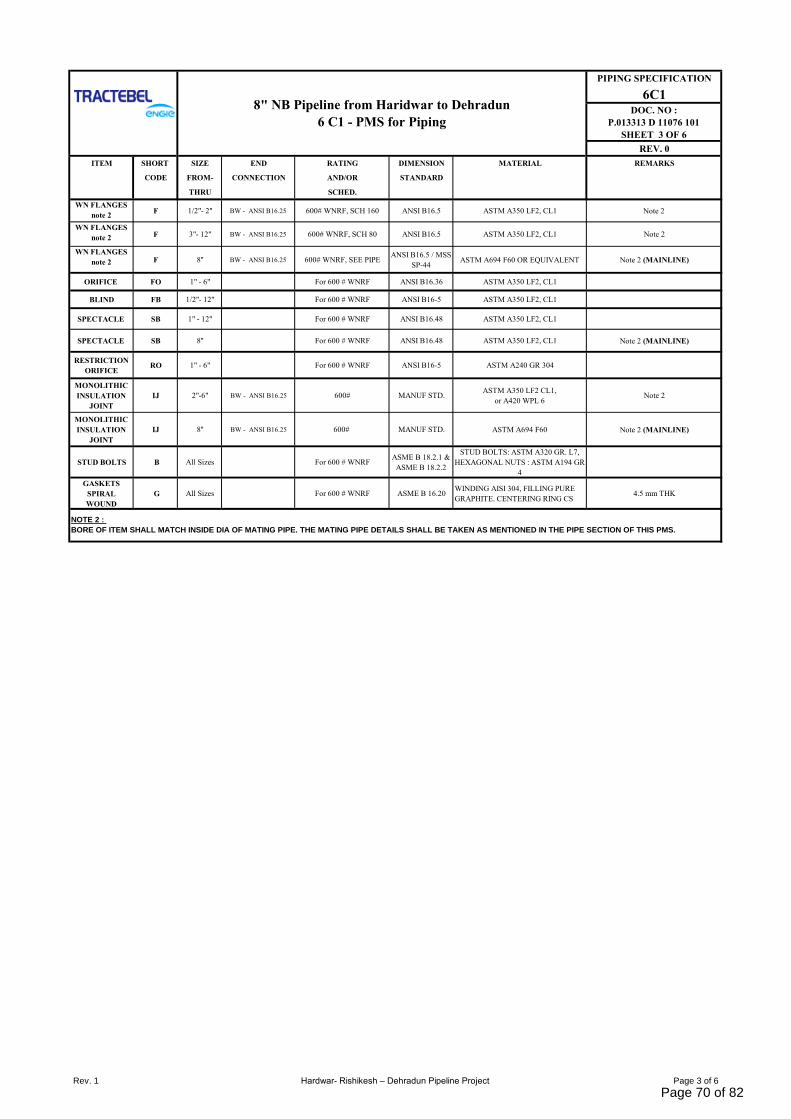
PIPING SPECIFICATION
6C1DOC. NO :
P.013313 D 11076 101
SHEET 3 OF 6
REV. 0
ITEM SHORT SIZE END RATING DIMENSION MATERIAL REMARKS
CODE FROM- CONNECTION AND/OR STANDARD
THRU SCHED.
WN FLANGES
note 2F 1/2"- 2" BW - ANSI B16.25 600# WNRF, SCH 160 ANSI B16.5 ASTM A350 LF2, CL1 Note 2
WN FLANGES
note 2 F 3"- 12" BW - ANSI B16.25 600# WNRF, SCH 80 ANSI B16.5 ASTM A350 LF2, CL1 Note 2
WN FLANGES
note 2 F 8'' BW - ANSI B16.25 600# WNRF, SEE PIPEANSI B16.5 / MSS
SP-44ASTM A694 F60 OR EQUIVALENT Note 2 (MAINLINE)
ORIFICE FO 1" - 6" For 600 # WNRF ANSI B16.36 ASTM A350 LF2, CL1
BLIND FB 1/2"- 12" For 600 # WNRF ANSI B16-5 ASTM A350 LF2, CL1
SPECTACLE SB 1" - 12" For 600 # WNRF ANSI B16.48 ASTM A350 LF2, CL1
SPECTACLE SB 8'' For 600 # WNRF ANSI B16.48 ASTM A350 LF2, CL1 Note 2 (MAINLINE)
RESTRICTION
ORIFICERO 1" - 6" For 600 # WNRF ANSI B16-5 ASTM A240 GR 304
MONOLITHIC
INSULATION
JOINT
IJ 2"-6" BW - ANSI B16.25 600# MANUF STD.ASTM A350 LF2 CL1,
or A420 WPL 6Note 2
MONOLITHIC
INSULATION
JOINT
IJ 8'' BW - ANSI B16.25 600# MANUF STD. ASTM A694 F60 Note 2 (MAINLINE)
STUD BOLTS B All Sizes For 600 # WNRFASME B 18.2.1 &
ASME B 18.2.2
STUD BOLTS: ASTM A320 GR. L7,
HEXAGONAL NUTS : ASTM A194 GR
4
GASKETS
SPIRAL
WOUND
G All Sizes For 600 # WNRF ASME B 16.20WINDING AISI 304, FILLING PURE
GRAPHITE. CENTERING RING CS4.5 mm THK
NOTE 2 :
BORE OF ITEM SHALL MATCH INSIDE DIA OF MATING PIPE. THE MATING PIPE DETAILS SHALL BE TAKEN AS MENTIONED IN THE PIPE SECTION OF THIS PMS.
8" NB Pipeline from Haridwar to Dehradun
6 C1 - PMS for Piping
Rev. 1 Hardwar- Rishikesh – Dehradun Pipeline Project Page 3 of 6
Page 70 of 82
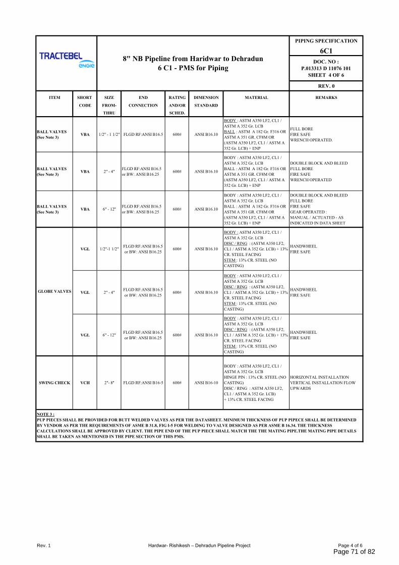
PIPING SPECIFICATION
6C1
DOC. NO :
P.013313 D 11076 101
SHEET 4 OF 6
REV. 0
ITEM SHORT SIZE END RATING DIMENSION MATERIAL REMARKS
CODE FROM- CONNECTION AND/OR STANDARD
THRU SCHED.
BALL VALVES
(See Note 3)VBA 1/2" - 1 1/2" FLGD RF:ANSI B16.5 600# ANSI B16.10
BODY : ASTM A350 LF2, CL1 /
ASTM A 352 Gr. LCB
BALL : ASTM A 182 Gr. F316 OR
ASTM A 351 GR. CF8M OR
(ASTM A350 LF2, CL1 / ASTM A
352 Gr. LCB) + ENP
FULL BORE
FIRE SAFE
WRENCH OPERATED.
BALL VALVES
(See Note 3)VBA 2" - 4"
FLGD RF:ANSI B16.5
or BW: ANSI B16.25600# ANSI B16.10
BODY : ASTM A350 LF2, CL1 /
ASTM A 352 Gr. LCB
BALL : ASTM A 182 Gr. F316 OR
ASTM A 351 GR. CF8M OR
(ASTM A350 LF2, CL1 / ASTM A
352 Gr. LCB) + ENP
DOUBLE BLOCK AND BLEED
FULL BORE
FIRE SAFE
WRENCH OPERATED
BALL VALVES
(See Note 3)VBA 6" - 12''
FLGD RF:ANSI B16.5
or BW: ANSI B16.25600# ANSI B16.10
BODY : ASTM A350 LF2, CL1 /
ASTM A 352 Gr. LCB
BALL : ASTM A 182 Gr. F316 OR
ASTM A 351 GR. CF8M OR
(ASTM A350 LF2, CL1 / ASTM A
352 Gr. LCB) + ENP
DOUBLE BLOCK AND BLEED
FULL BORE
FIRE SAFE
GEAR OPERATED :
MANUAL / ACTUATED - AS
INDICATED IN DATA SHEET
VGL 1/2"-1 1/2"FLGD RF:ANSI B16.5
or BW: ANSI B16.25600# ANSI B16.10
BODY : ASTM A350 LF2, CL1 /
ASTM A 352 Gr. LCB
DISC / RING : (ASTM A350 LF2,
CL1 / ASTM A 352 Gr. LCB) + 13%
CR. STEEL FACING
STEM : 13% CR. STEEL (NO
CASTING)
HANDWHEEL
FIRE SAFE
VGL 2" - 4"FLGD RF:ANSI B16.5
or BW: ANSI B16.25600# ANSI B16.10
BODY : ASTM A350 LF2, CL1 /
ASTM A 352 Gr. LCB
DISC / RING : (ASTM A350 LF2,
CL1 / ASTM A 352 Gr. LCB) + 13%
CR. STEEL FACING
STEM : 13% CR. STEEL (NO
CASTING)
HANDWHEEL
FIRE SAFE
VGL 6" - 12"FLGD RF:ANSI B16.5
or BW: ANSI B16.25600# ANSI B16.10
BODY : ASTM A350 LF2, CL1 /
ASTM A 352 Gr. LCB
DISC / RING : (ASTM A350 LF2,
CL1 / ASTM A 352 Gr. LCB) + 13%
CR. STEEL FACING
STEM : 13% CR. STEEL (NO
CASTING)
HANDWHEEL
FIRE SAFE
SWING CHECK VCH 2"- 8'' FLGD RF:ANSI B16-5 600# ANSI B16-10
BODY : ASTM A350 LF2, CL1 /
ASTM A 352 Gr. LCB
HINGE PIN : 13% CR. STEEL (NO
CASTING)
DISC / RING : ASTM A350 LF2,
CL1 / ASTM A 352 Gr. LCB)
+ 13% CR. STEEL FACING
HORIZONTAL INSTALLATION
VERTICAL INSTALLATION FLOW
UPWARDS
NOTE 3 :
PUP PIECES SHALL BE PROVIDED FOR BUTT WELDED VALVES AS PER THE DATASHEET. MINIMUM THICKNESS OF PUP PIPECE SHALL BE DETERMINED
BY VENDOR AS PER THE REQUIREMENTS OF ASME B 31.8, FIG I-5 FOR WELDING TO VALVE DESIGNED AS PER ASME B 16.34. THE THICKNESS
CALCULATIONS SHALL BE APPROVED BY CLIENT. THE PIPE END OF THE PUP PIECE SHALL MATCH THE THE MATING PIPE.THE MATING PIPE DETAILS
SHALL BE TAKEN AS MENTIONED IN THE PIPE SECTION OF THIS PMS.
8" NB Pipeline from Haridwar to Dehradun
6 C1 - PMS for Piping
GLOBE VALVES
Rev. 1 Hardwar- Rishikesh – Dehradun Pipeline Project Page 4 of 6
Page 71 of 82

PIPING SPECIFICATION
6C1
DOC. NO :
P.013313 D 11076 101
SHEET 5 OF 6
REV. 0
SMALL SIZE
1/2"3/4" 1" 1.1/2" 2" 3" 4" 6" 8" 10" 12" 14" 16" 18" 20"
1/2"
3/4" X
1" X X
L 1.1/2" X X X
A 2" X X X
R 3" X X
G 4" X X X
E 6" X X
8" X X
S 10" X X X
I 12" X X X
z 14" X X X X
E 16" X X X X
18" X X X X
20" X X X X
24" X X X
LEGENDX : CONCENTRIC AND ECCENTRIC REDUCERS- BW
REDUCERS CHART
8" NB Pipeline from Haridwar to Dehradun
6 C1 - PMS for Piping
Rev. 1 Hardwar- Rishikesh – Dehradun Pipeline Project Page 5 of 6
Page 72 of 82
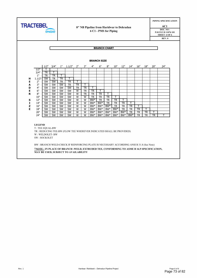
BRANCH SIZE
1/2" 3/4" 1" 1.1/2" 2" 3" 4" 6" 8" 10" 12" 14" 16" 18" 20" 24"
1/2" T
3/4" TR T
1" TR TR T
H 1.1/2" SW TR TR T
E 2" SW SW TR TR T
A 3" SW SW SW TR TR T
D 4" SW SW SW SW TR TR T
E 6" SW SW SW SW W TR TR T
R 8" SW SW SW SW W TR TR TR T
10" SW SW SW SW W W TR TR TR T
S 12" SW SW SW SW W W BW* TR TR TR T
I 14" SW SW SW SW W W BW* BW* TR TR TR T
Z 16" SW SW SW SW W W BW* BW* BW* TR TR TR T
E 18" SW SW SW SW W W BW* BW* BW* BW* TR TR TR T
20" SW SW SW SW W W BW* BW* BW* BW* BW* TR TR TR T
24" SW SW SW SW W W BW* BW* BW* BW* BW* BW* TR TR TR T
LEGEND
T : TEE EQUAL-BW
TR : REDUCING TEE-BW (FLOW TEE WHEREVER INDICATED SHALL BE PROVIDED)
W : WELDOLET- BW
SW : SOCKOLET
BW : BRANCH WELD-CHECK IF REINFORCING PLATE IS NECESSARY ACCORDING ANSI B 31.8 (See Note)
*NOTE : IN PLACE OF BRANCH -WELD, EXTRUDED TEE, CONFORMING TO ASME B 16.9 SPECIFICATION,
MAY BE USED, SUBJECT TO AVAILABILITY
6C1DOC. NO :
P.013313 D 11076 101
SHEET 6 OF 6
REV. 0
BRANCH CHART
8" NB Pipeline from Haridwar to Dehradun
6 C1 - PMS for Piping
PIPING SPECIFICATION
Rev. 1 Hardwar- Rishikesh – Dehradun Pipeline Project Page 6 of 6
Page 73 of 82
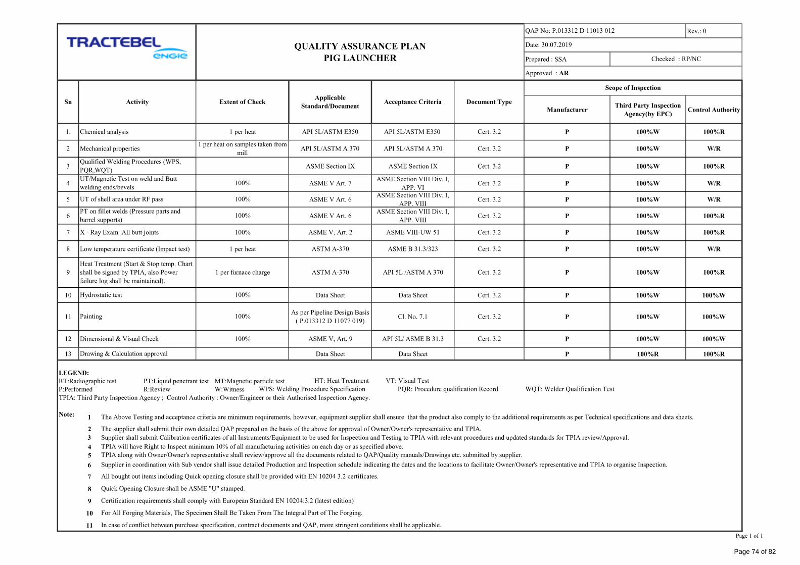
Rev.: 0
Prepared : SSA
ManufacturerThird Party Inspection
Agency(by EPC)Control Authority
3 ASME Section IX ASME Section IX Cert. 3.2 P 100%W 100%R
4 ASME V Art. 7ASME Section VIII Div. I,
APP. VICert. 3.2 P 100%W W/R
5 ASME V Art. 6ASME Section VIII Div. I,
APP. VIIICert. 3.2 P 100%W W/R
6 ASME V Art. 6ASME Section VIII Div. I,
APP. VIIICert. 3.2 P 100%W 100%R
10 Data Sheet Data Sheet Cert. 3.2 P 100%W 100%W
11As per Pipeline Design Basis
( P.013312 D 11077 019)Cl. No. 7.1 Cert. 3.2 P 100%W 100%W
13 Data Sheet Data Sheet P 100%R 100%R
LEGEND:
RT:Radiographic test PT:Liquid penetrant test MT:Magnetic particle test
P:Performed R:Review W:Witness
TPIA: Third Party Inspection Agency ; Control Authority : Owner/Engineer or their Authorised Inspection Agency.
Note:
2 The supplier shall submit their own detailed QAP prepared on the basis of the above for approval of Owner/Owner's representative and TPIA.
4
5
6
7
8
9
10
11
API 5L /ASTM A 370
100%
Acceptance Criteria Document Type
ASME V, Art. 2
ASTM A-370 Cert. 3.2
API 5L/ASTM E350
API 5L/ASTM A 3701 per heat on samples taken from
millAPI 5L/ASTM A 370
Cert. 3.2
Cert. 3.2
1 per heat API 5L/ASTM E350
All bought out items including Quick opening closure shall be provided with EN 10204 3.2 certificates.
QAP No: P.013312 D 11013 012
Date: 30.07.2019
Approved : AR
100%W
100%R
100%R
Supplier shall submit Calibration certificates of all Instruments/Equipment to be used for Inspection and Testing to TPIA with relevant procedures and updated standards for TPIA review/Approval.
QUALITY ASSURANCE PLAN
PIG LAUNCHER
Applicable
Standard/Document
100%R
100%
Sn Activity Extent of Check
1. Chemical analysis P
Scope of Inspection
W/R
7 X - Ray Exam. All butt joints P 100%W
100%
2 Mechanical properties P 100%W
ASME VIII-UW 51
9
Heat Treatment (Start & Stop temp. Chart
shall be signed by TPIA, also Power
failure log shall be maintained).
P 100%W
Hydrostatic test
8 Low temperature certificate (Impact test) P 100%WASME B 31.3/323
12 Dimensional & Visual Check P 100%W
HT: Heat Treatment VT: Visual Test
WPS: Welding Procedure Specification PQR: Procedure qualification Record WQT: Welder Qualification Test
Cert. 3.2API 5L/ ASME B 31.3
TPIA along with Owner/Owner's representative shall review/approve all the documents related to QAP/Quality manuals/Drawings etc. submitted by supplier.
Supplier in coordination with Sub vendor shall issue detailed Production and Inspection schedule indicating the dates and the locations to facilitate Owner/Owner's representative and TPIA to organise Inspection.
100%W
Drawing & Calculation approval
1 The Above Testing and acceptance criteria are minimum requirements, however, equipment supplier shall ensure that the product also comply to the additional requirements as per Technical specifications and data sheets.
3
100% ASME V, Art. 9
1 per heat
1 per furnace charge
100%
TPIA will have Right to Inspect minimum 10% of all manufacturing activities on each day or as specified above.
W/R
Painting 100%
Cert. 3.2
Cert. 3.2ASTM A-370
For All Forging Materials, The Specimen Shall Be Taken From The Integral Part of The Forging.
In case of conflict between purchase specification, contract documents and QAP, more stringent conditions shall be applicable.
Certification requirements shall comply with European Standard EN 10204:3.2 (latest edition)
Checked : RP/NC
Quick Opening Closure shall be ASME "U" stamped.
100%
Qualified Welding Procedures (WPS,
PQR,WQT)
UT/Magnetic Test on weld and Butt
welding ends/bevels
UT of shell area under RF pass
PT on fillet welds (Pressure parts and
barrel supports)
Page 1 of 1
Page 74 of 82
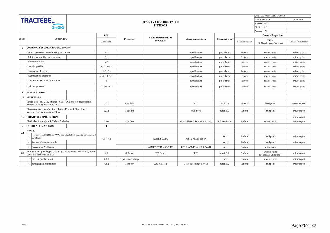
Date: 30.07.2019 Revision: 0
Prepared : GG
Checked : RP
Approved : AR
PTS
Clause No. ManufacturerTPIA
(By Manufacturer / Contractor)Control Authority
0
- list of operation in manufacturing and control 9.1 specification procedures Perform review point review point
- Fabrication and Control procedure 9.1 specification procedures Perform review point review point
2.7 specification procedures Perform review point review point
9.1; 2 and 3 specification procedures Perform review point review point
9.2 ; 2 specification procedures Perform review point review point
2, 4, 5, 6 & 7 specification procedures Perform review point review point
6 specification procedures Perform review point review point
As per PTS specification procedures Perform review point review point
1 BASE MATERIAL
1.1 MATERIALS
5.1.1 1 per heat PTS certif. 3.2 Perform hold point review report
5.1.2 1 per heat Mat. Spec. certif. 3.2 Perform hold point review report
1.2 CHEMICAL COMPOSITION review report
3.10 1 per heat PTS-Table1+ ASTM & Mat. Spec. Lab certificate Perform review report review report
2 FABRICATION & TESTS 4
- report Perform hold point review report
- Review of welders records report Perform hold point review report
- Consumable Verification ASME SEC IX / SEC IIC PTS & ASME Sec-IX & Sec-II report Perform review point
2.2 4.3 all fittings T/T Graph PTS certif. 3.2 PerformWitness Point
(Loading & Unloading)review report
- time temperature chart 4.3.1 1 per furnace charge report Perform review report review report
- micrographic examination 4.3.2 1 per lot* ASTM E 112 Grain size : range 8 to 12 certif. 3.2 Perform hold point review report
ACTIVITY
CONTROL BEFORE MANUFACTURING
- material part list
PTS & ASME Sec-IX
- painting procedure
Tensile tests (YS, UTS, YS/UTS, %EL, RA, Bend etc. as applicable)
(remark : marking transfer by TPIA)
Charpy-test at as per Mat. Spec. (Impact Energy & Shear Area)
(remark : marking transfer by TPIA)
- Design Proof test
Check chemical analysis & Carbon Equivalent
ASME SEC IX
Welding
Review of WPS (If New WPS has established, same to be witnessed
by TPIA) 4.1 & 4.2
2.1
Applicable standard &
ProcedureAcceptance criteria
Heat treatment (Loading & Unloading shall be witnessed by TPIA, Power
failure log shall be maintained)
S NO.
- heat treatment procedure
- non destructive testing procedures
- dimensional drawings
QUALITY CONTROL TABLE
FITTINGS
Scope of Inspection
QCT No. : P.013312 D 11013 003
Frequency Document type
Rev.0 SULTANPUR JHAJJAR HISAR PIPELINE (SJHPL) PROJECT Page 1 of 3Page 75 of 82
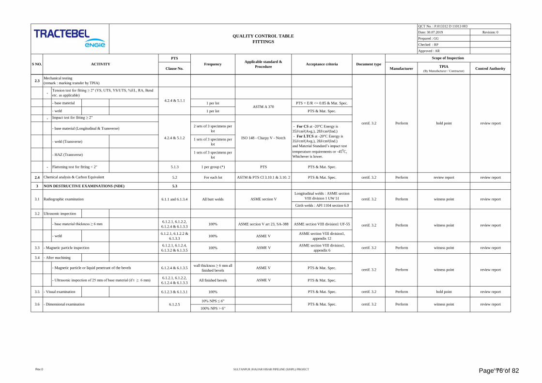
Date: 30.07.2019 Revision: 0
Prepared : GG
Checked : RP
Approved : AR
PTS
Clause No. ManufacturerTPIA
(By Manufacturer / Contractor)Control Authority
ACTIVITYApplicable standard &
ProcedureAcceptance criteriaS NO.
QUALITY CONTROL TABLE
FITTINGS
Scope of Inspection
QCT No. : P.013312 D 11013 003
Frequency Document type
2.3
-
- base material 1 per lot PTS + E/R <= 0.85 & Mat. Spec.
- weld 1 per lot PTS & Mat. Spec.
-
- base material (Longitudinal & Transverse)2 sets of 3 specimens per
lot
- weld (Transverse)1 sets of 3 specimens per
lot
- HAZ (Transverse)1 sets of 3 specimens per
lot
- Flattening test for fitting < 2" 5.1.3 1 per group (*) PTS PTS & Mat. Spec.
2.4 5.2 For each lot ASTM & PTS Cl 3.10.1 & 3.10. 2 PTS & Mat. Spec. certif. 3.2 Perform review report review report
3 NON DESTRUCTIVE EXAMINATIONS (NDE) 5.3
Longitudinal welds : ASME section
VIII division 1 UW 51
Girth welds : API 1104 section 6.0
3.2 Ultrasonic inspection
- base material thickness ≥ 6 mm6.1.2.1, 6.1.2.2,
6.1.2.4 & 6.1.3.3100% ASME section V art 23, SA-388 ASME section VIII division1 UF-55
- weld6.1.2.1, 6.1.2.2 &
6.1.3.3100% ASME V
ASME section VIII division1,
appendix 12
3.3 - Magnetic particle inspection6.1.2.1, 6.1.2.4,
6.1.3.2 & 6.1.3.5100% ASME V
ASME section VIII division1,
appendix 6certif. 3.2 Perform witness point review report
3.4 - After machining
- Magnetic particle or liquid penetrant of the bevels 6.1.2.4 & 6.1.3.5 wall thickness ≥ 6 mm all
finished bevelsASME V PTS & Mat. Spec.
- Ultrasonic inspection of 25 mm of base material (if t ≥ 6 mm)6.1.2.1, 6.1.2.2,
6.1.2.4 & 6.1.3.3All finished bevels ASME V PTS & Mat. Spec.
3.5 - Visual examination 6.1.2.3 & 6.1.3.1 100% PTS & Mat. Spec. certif. 3.2 Perform hold point review report
10% NPS ≤ 6"
100% NPS > 6"
Impact test for fitting ≥ 2"
ASTM A 370
3.1 6.1.1 and 6.1.3.4 All butt welds ASME section V witness point review reportPerform
hold point review reportcertif. 3.2 Perform
- Dimensional examination Perform
certif. 3.2 witness point
Mechanical testing
(remark : marking transfer by TPIA)
review reportPerform
Perform
3.6 certif. 3.2
Chemical analysis & Carbon Equivalent
Radiographic examination certif. 3.2
- For CS at -20°C Energy is
35J/cm²(Avg.), 28J/cm²(Ind.)
- For LTCS at -20°C Energy is
35J/cm²(Avg.), 28J/cm²(Ind.)
and Material Standard’s impact test
temperature requirements or -450C,
Whichever is lower.
4.2.4 & 5.1.2
4.2.4 & 5.1.1
Tension test for fitting ≥ 2" (YS, UTS, YS/UTS, %EL, RA, Bend
etc. as applicable)
review report
ISO 148 - Charpy V - Notch
certif. 3.2 witness point
PTS & Mat. Spec.6.1.2.5 witness point review report
Rev.0 SULTANPUR JHAJJAR HISAR PIPELINE (SJHPL) PROJECT Page 2 of 3Page 76 of 82
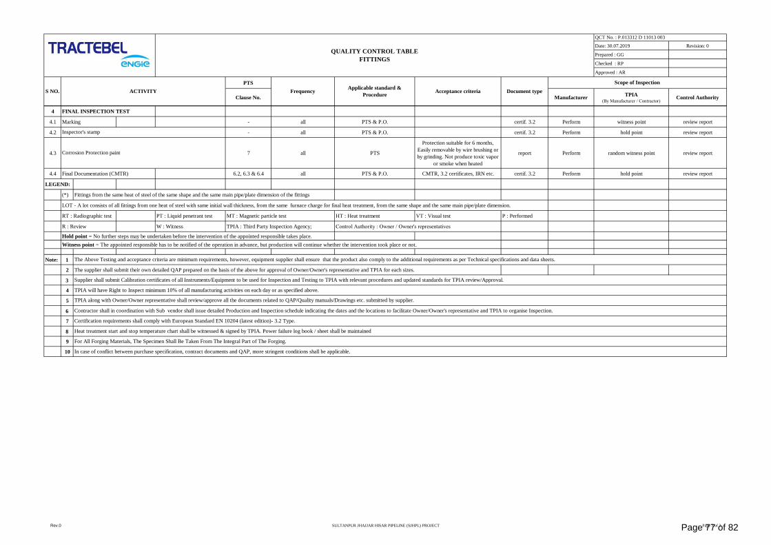
Date: 30.07.2019 Revision: 0
Prepared : GG
Checked : RP
Approved : AR
PTS
Clause No. ManufacturerTPIA
(By Manufacturer / Contractor)Control Authority
ACTIVITYApplicable standard &
ProcedureAcceptance criteriaS NO.
QUALITY CONTROL TABLE
FITTINGS
Scope of Inspection
QCT No. : P.013312 D 11013 003
Frequency Document type
4 FINAL INSPECTION TEST
4.1 Marking - all PTS & P.O. certif. 3.2 Perform witness point review report
4.2 - all PTS & P.O. certif. 3.2 Perform hold point review report
4.3 7 all PTS
Protection suitable for 6 months,
Easily removable by wire brushing or
by grinding. Not produce toxic vapor
or smoke when heated
report Perform random witness point review report
4.4 Final Documentation (CMTR) 6.2, 6.3 & 6.4 all PTS & P.O. CMTR, 3.2 certificates, IRN etc. certif. 3.2 Perform hold point review report
LEGEND:
(*) Fittings from the same heat of steel of the same shape and the same main pipe/plate dimension of the fittings
LOT - A lot consists of all fittings from one heat of steel with same initial wall thickness, from the same furnace charge for final heat treatment, from the same shape and the same main pipe/plate dimension.
RT : Radiographic test PT : Liquid penetrant test MT : Magnetic particle test HT : Heat treatment VT : Visual test P : Performed
R : Review W : Witness TPIA : Third Party Inspection Agency; Control Authority : Owner / Owner's representatives
Hold point = No further steps may be undertaken before the intervention of the appointed responsible takes place.
Witness point = The appointed responsible has to be notified of the operation in advance, but production will continue whether the intervention took place or not.
Note: 1
2 The supplier shall submit their own detailed QAP prepared on the basis of the above for approval of Owner/Owner's representative and TPIA for each sizes.
3
4
5
6
7
8
9
10 In case of conflict between purchase specification, contract documents and QAP, more stringent conditions shall be applicable.
Heat treatment start and stop temperature chart shall be witnessed & signed by TPIA. Power failure log book / sheet shall be maintained
For All Forging Materials, The Specimen Shall Be Taken From The Integral Part of The Forging.
Corrosion Protection paint
The Above Testing and acceptance criteria are minimum requirements, however, equipment supplier shall ensure that the product also comply to the additional requirements as per Technical specifications and data sheets.
Certification requirements shall comply with European Standard EN 10204 (latest edition)- 3.2 Type.
TPIA along with Owner/Owner representative shall review/approve all the documents related to QAP/Quality manuals/Drawings etc. submitted by supplier.
Contractor shall in coordination with Sub vendor shall issue detailed Production and Inspection schedule indicating the dates and the locations to facilitate Owner/Owner's representative and TPIA to organise Inspection.
Inspector's stamp
Supplier shall submit Calibration certificates of all Instruments/Equipment to be used for Inspection and Testing to TPIA with relevant procedures and updated standards for TPIA review/Approval.
TPIA will have Right to Inspect minimum 10% of all manufacturing activities on each day or as specified above.
Rev.0 SULTANPUR JHAJJAR HISAR PIPELINE (SJHPL) PROJECT Page 3 of 3Page 77 of 82
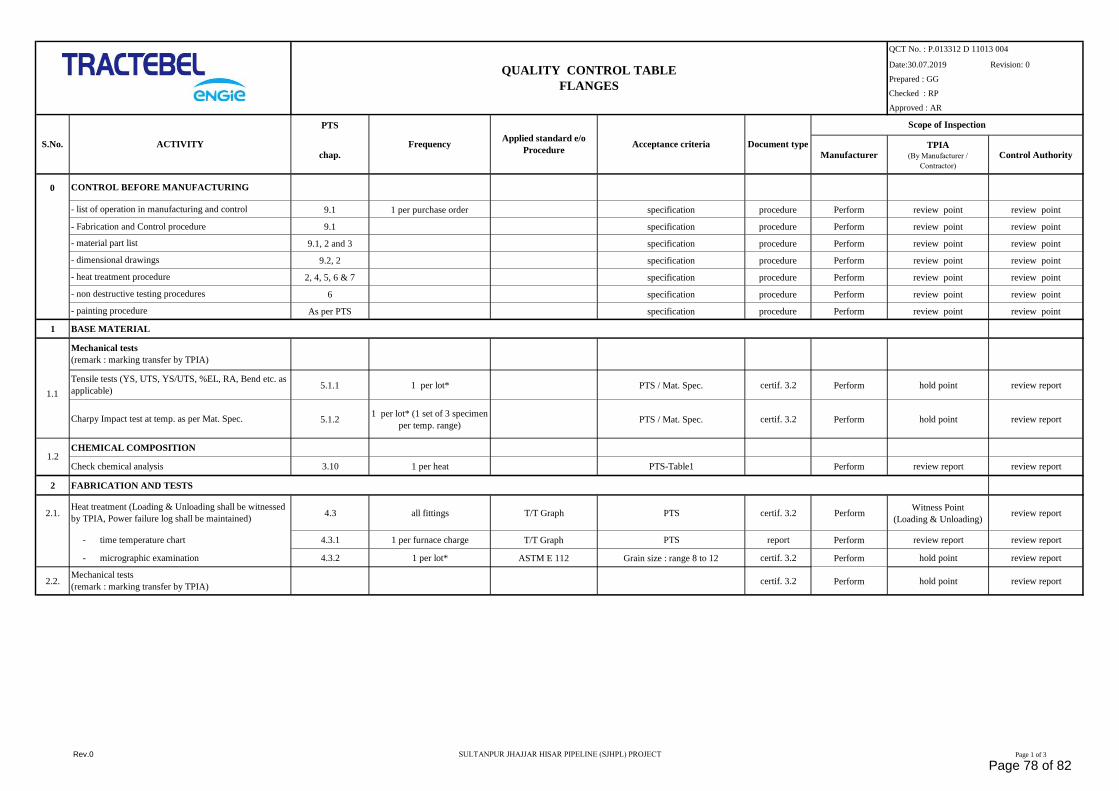
Date:30.07.2019 Revision: 0
Prepared : GG
Checked : RP
Approved : AR
PTS
chap. ManufacturerTPIA
(By Manufacturer /
Contractor)
Control Authority
0
9.1 1 per purchase order specification procedure Perform review point review point
- Fabrication and Control procedure 9.1 specification procedure Perform review point review point
9.1, 2 and 3 specification procedure Perform review point review point
9.2, 2 specification procedure Perform review point review point
2, 4, 5, 6 & 7 specification procedure Perform review point review point
6 specification procedure Perform review point review point
As per PTS specification procedure Perform review point review point
1 BASE MATERIAL
5.1.1 1 per lot* PTS / Mat. Spec. certif. 3.2 Perform hold point review report
5.1.21 per lot* (1 set of 3 specimen
per temp. range)PTS / Mat. Spec. certif. 3.2 Perform hold point review report
CHEMICAL COMPOSITION
Check chemical analysis 3.10 1 per heat PTS-Table1 Perform review report review report
2 FABRICATION AND TESTS
2.1. 4.3 all fittings T/T Graph PTS certif. 3.2 PerformWitness Point
(Loading & Unloading)review report
- time temperature chart 4.3.1 1 per furnace charge T/T Graph PTS report Perform review report review report
- micrographic examination 4.3.2 1 per lot* ASTM E 112 Grain size : range 8 to 12 certif. 3.2 Perform hold point review report
2.2. certif. 3.2 Perform hold point review report
S.No.
- material part list
1.2
1.1
Applied standard e/o
ProcedureAcceptance criteria
Tensile tests (YS, UTS, YS/UTS, %EL, RA, Bend etc. as
applicable)
- non destructive testing procedures
- list of operation in manufacturing and control
Charpy Impact test at temp. as per Mat. Spec.
- painting procedure
QUALITY CONTROL TABLE
FLANGES
CONTROL BEFORE MANUFACTURING
Document type
- dimensional drawings
ACTIVITY
- heat treatment procedure
Mechanical tests
(remark : marking transfer by TPIA)
Frequency
Mechanical tests
(remark : marking transfer by TPIA)
Heat treatment (Loading & Unloading shall be witnessed
by TPIA, Power failure log shall be maintained)
Scope of Inspection
QCT No. : P.013312 D 11013 004
Rev.0 SULTANPUR JHAJJAR HISAR PIPELINE (SJHPL) PROJECT Page 1 of 3
Page 78 of 82
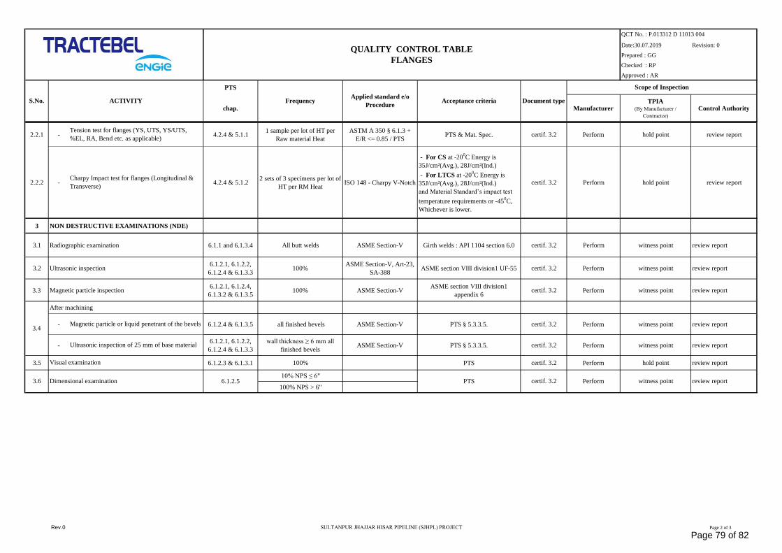
Date:30.07.2019 Revision: 0
Prepared : GG
Checked : RP
Approved : AR
PTS
chap. ManufacturerTPIA
(By Manufacturer /
Contractor)
Control Authority
S.No.Applied standard e/o
ProcedureAcceptance criteria
QUALITY CONTROL TABLE
FLANGES
CONTROL BEFORE MANUFACTURING
Document typeACTIVITY Frequency
Scope of Inspection
QCT No. : P.013312 D 11013 004
2.2.1 - 4.2.4 & 5.1.11 sample per lot of HT per
Raw material Heat
ASTM A 350 § 6.1.3 +
E/R <= 0.85 / PTSPTS & Mat. Spec. certif. 3.2 Perform hold point review report
2.2.2 - 4.2.4 & 5.1.22 sets of 3 specimens per lot of
HT per RM HeatISO 148 - Charpy V-Notch
- For CS at -200C Energy is
35J/cm²(Avg.), 28J/cm²(Ind.)
- For LTCS at -200C Energy is
35J/cm²(Avg.), 28J/cm²(Ind.)
and Material Standard’s impact test
temperature requirements or -450C,
Whichever is lower.
certif. 3.2 Perform hold point review report
3 NON DESTRUCTIVE EXAMINATIONS (NDE)
3.1 Radiographic examination 6.1.1 and 6.1.3.4 All butt welds ASME Section-V Girth welds : API 1104 section 6.0 certif. 3.2 Perform witness point review report
3.2 Ultrasonic inspection6.1.2.1, 6.1.2.2,
6.1.2.4 & 6.1.3.3100%
ASME Section-V, Art-23,
SA-388ASME section VIII division1 UF-55 certif. 3.2 Perform witness point review report
3.3 Magnetic particle inspection6.1.2.1, 6.1.2.4,
6.1.3.2 & 6.1.3.5100% ASME Section-V
ASME section VIII division1
appendix 6certif. 3.2 Perform witness point review report
After machining
- 6.1.2.4 & 6.1.3.5 all finished bevels ASME Section-V PTS § 5.3.3.5. certif. 3.2 Perform witness point review report
-6.1.2.1, 6.1.2.2,
6.1.2.4 & 6.1.3.3
wall thickness ≥ 6 mm all
finished bevelsASME Section-V PTS § 5.3.3.5. certif. 3.2 Perform witness point review report
3.5 6.1.2.3 & 6.1.3.1 100% PTS certif. 3.2 Perform hold point review report
10% NPS ≤ 6"
100% NPS > 6"3.6
Charpy Impact test for flanges (Longitudinal &
Transverse)
PTS
Tension test for flanges (YS, UTS, YS/UTS,
%EL, RA, Bend etc. as applicable)
Performcertif. 3.2 witness point review reportDimensional examination 6.1.2.5
Magnetic particle or liquid penetrant of the bevels
Ultrasonic inspection of 25 mm of base material
Visual examination
3.4
Rev.0 SULTANPUR JHAJJAR HISAR PIPELINE (SJHPL) PROJECT Page 2 of 3
Page 79 of 82
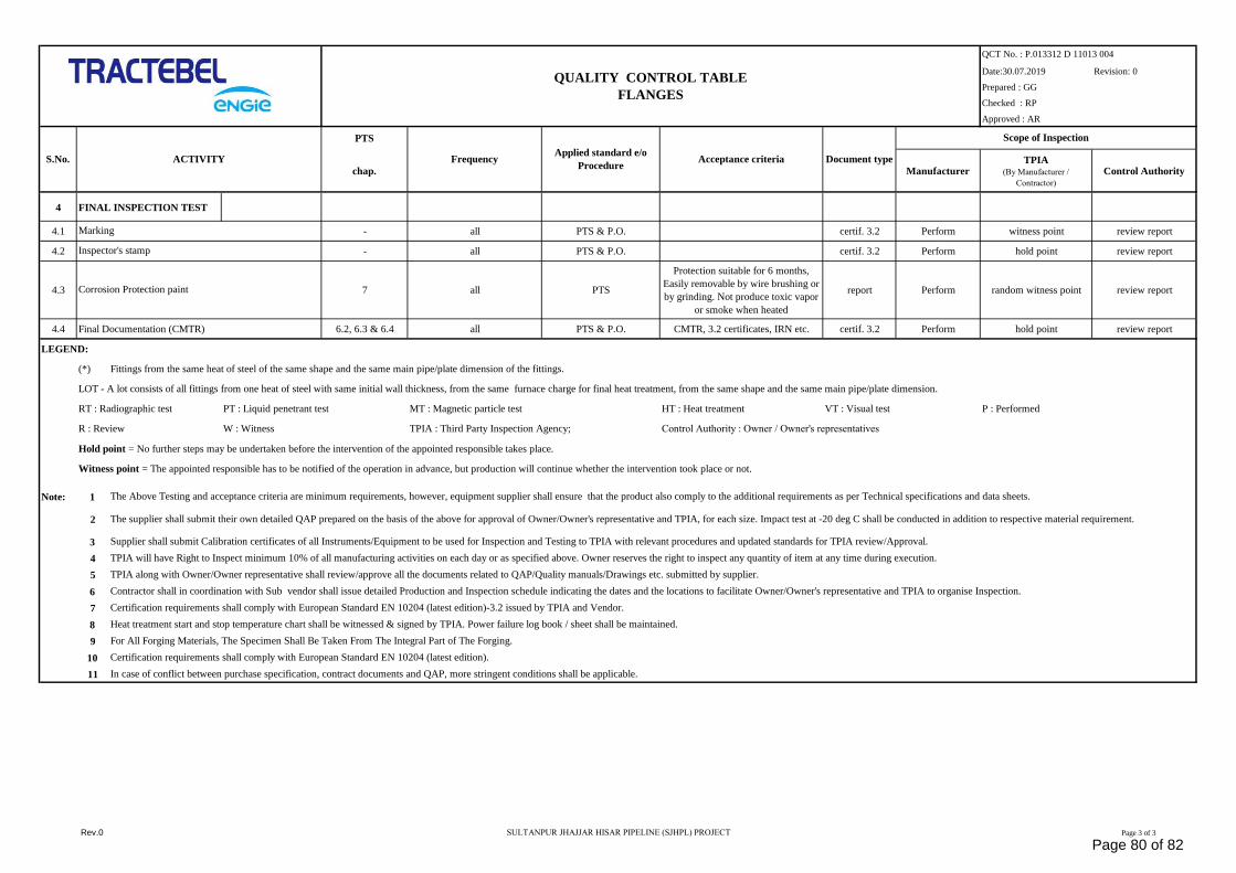
Date:30.07.2019 Revision: 0
Prepared : GG
Checked : RP
Approved : AR
PTS
chap. ManufacturerTPIA
(By Manufacturer /
Contractor)
Control Authority
S.No.Applied standard e/o
ProcedureAcceptance criteria
QUALITY CONTROL TABLE
FLANGES
CONTROL BEFORE MANUFACTURING
Document typeACTIVITY Frequency
Scope of Inspection
QCT No. : P.013312 D 11013 004
4 FINAL INSPECTION TEST
4.1 - all PTS & P.O. certif. 3.2 Perform witness point review report
4.2 - all PTS & P.O. certif. 3.2 Perform hold point review report
4.3 7 all PTS
Protection suitable for 6 months,
Easily removable by wire brushing or
by grinding. Not produce toxic vapor
or smoke when heated
report Perform random witness point review report
4.4 Final Documentation (CMTR) 6.2, 6.3 & 6.4 all PTS & P.O. CMTR, 3.2 certificates, IRN etc. certif. 3.2 Perform hold point review report
LEGEND:
(*) Fittings from the same heat of steel of the same shape and the same main pipe/plate dimension of the fittings.
LOT - A lot consists of all fittings from one heat of steel with same initial wall thickness, from the same furnace charge for final heat treatment, from the same shape and the same main pipe/plate dimension.
RT : Radiographic test PT : Liquid penetrant test MT : Magnetic particle test HT : Heat treatment VT : Visual test P : Performed
R : Review W : Witness TPIA : Third Party Inspection Agency; Control Authority : Owner / Owner's representatives
Hold point = No further steps may be undertaken before the intervention of the appointed responsible takes place.
Witness point = The appointed responsible has to be notified of the operation in advance, but production will continue whether the intervention took place or not.
Note: 1
2
3
4
5
6
7
8
9
10
11
Certification requirements shall comply with European Standard EN 10204 (latest edition).
In case of conflict between purchase specification, contract documents and QAP, more stringent conditions shall be applicable.
Marking
Inspector's stamp
Corrosion Protection paint
Heat treatment start and stop temperature chart shall be witnessed & signed by TPIA. Power failure log book / sheet shall be maintained.
For All Forging Materials, The Specimen Shall Be Taken From The Integral Part of The Forging.
The supplier shall submit their own detailed QAP prepared on the basis of the above for approval of Owner/Owner's representative and TPIA, for each size. Impact test at -20 deg C shall be conducted in addition to respective material requirement.
Certification requirements shall comply with European Standard EN 10204 (latest edition)-3.2 issued by TPIA and Vendor.
The Above Testing and acceptance criteria are minimum requirements, however, equipment supplier shall ensure that the product also comply to the additional requirements as per Technical specifications and data sheets.
Supplier shall submit Calibration certificates of all Instruments/Equipment to be used for Inspection and Testing to TPIA with relevant procedures and updated standards for TPIA review/Approval.
TPIA will have Right to Inspect minimum 10% of all manufacturing activities on each day or as specified above. Owner reserves the right to inspect any quantity of item at any time during execution.
TPIA along with Owner/Owner representative shall review/approve all the documents related to QAP/Quality manuals/Drawings etc. submitted by supplier.
Contractor shall in coordination with Sub vendor shall issue detailed Production and Inspection schedule indicating the dates and the locations to facilitate Owner/Owner's representative and TPIA to organise Inspection.
Rev.0 SULTANPUR JHAJJAR HISAR PIPELINE (SJHPL) PROJECT Page 3 of 3
Page 80 of 82
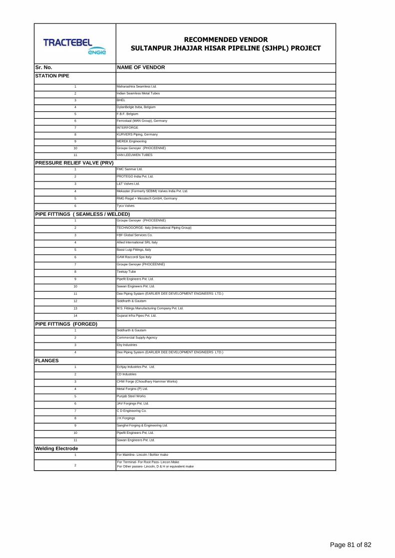
RECOMMENDED VENDOR
SULTANPUR JHAJJAR HISAR PIPELINE (SJHPL) PROJECT
Sr. No. NAME OF VENDOR
STATION PIPE
1 Maharashtra Seamless Ltd.
2 Indian Seamless Metal Tubes
3 BHEL
4 DylanBelgie bvba, Belgium
5 F.B.F. Belgium
6 Ferrostaal (MAN Group), Germany
7 INTERFORGE
8 KURVERS Piping, Germany
9 MEREK Engineering
10 Groupe Genoyer (PHOCEENNE)
11 VAN LEEUWEN TUBES
1 FMC Sanmar Ltd.
2 PROTEGO India Pvt. Ltd.
3 L&T Valves Ltd.
4 Mekaster (Formerly SEBIM) Valves India Pvt. Ltd.
5 RMG Regal + Messtech GmbH, Germany
6 Tyco Valves
1 Groupe Genoyer (PHOCEENNE)
2 TECHNOGORGE- Italy (International Piping Group)
3 FBF Global Services Co.
4 Allied International SRL Italy
5 Bassi Luigi Fittings, Italy
6 GAM Raccordi Spa Italy
7 Groupe Genoyer (PHOCEENNE)
8 Teekay Tube
9 Pipefit Engineers Pvt. Ltd.
10 Sawan Engineers Pvt. Ltd.
11 Dee Piping System (EARLIER DEE DEVELOPMENT ENGINEERS LTD.)
12 Siddharth & Gautam
13 M.S. Fittings Manufacturing Company Pvt. Ltd.
14 Gujarat Infra Pipes Pvt. Ltd.
PIPE FITTINGS (FORGED)1 Siddharth & Gautam
2 Commercial Supply Agency
3 Eby Industries
4 Dee Piping System (EARLIER DEE DEVELOPMENT ENGINEERS LTD.)
FLANGES1 Echjay Industries Pvt. Ltd.
2 CD Industries
3 CHW Forge (Choudhary Hammer Works)
4 Metal Forgins (P) Ltd.
5 Punjab Steel Works
6 JAV Forgings Pvt. Ltd.
7 C D Engineering Co.
8 J K Forgings
9 Sanghvi Forging & Engineering Ltd.
10 Pipefit Engineers Pvt. Ltd.
11 Sawan Engineers Pvt. Ltd.
Welding Electrode1 For Mainline- Lincoln / Bohler make
2For Terminal- For Root Pass- Lincon Make
For Other passes- Lincoln, D & H or equivalent make
PRESSURE RELIEF VALVE (PRV)
PIPE FITTINGS ( SEAMLESS / WELDED)
Page 81 of 82
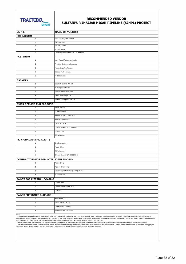
RECOMMENDED VENDOR
SULTANPUR JHAJJAR HISAR PIPELINE (SJHPL) PROJECT
Sr. No. NAME OF VENDOR
NDT Agencies1 NDT Services, Ahmedabad
2 RTD, Mumbai
3 Sievert , Mumbai
4 X-Tech- Vizag
5 Geecy Industrial Service Pvt. Ltd., Mumbai.
FASTENERS
1 Multi Thread Fasteners ,Baroda
2 Precision Engineering Industries
3 Nireka Engg. Co. Pvt. Ltd.
4 Deepak Fasteners Ltd.
5 Fix Fit Fasteners
GASKETS
1 Goodrich Gaskets Pvt. Ltd.
2 IGP Engineers Pvt. Ltd.
3 Madras Industrial Products
4 Banco Products (P) Ltd.
5 Starflex Sealing India Pvt. Ltd.
1 Forain Srl, Italy
2 G.D.Engineering
3 Perry Equipment Corporation
4 Pipeline Engineering
5 Siirtec Nigi S.p.A
6 Groupe Genoyer (PHOCEENNE)
7 Rosen Group
8 TD Williamson
1 G.D.Engineering
2 Forain S.R.L
3 TD Williamson
4 Groupe Genoyer (PHOCEENNE)
1 Rosen Group
2 Pipeline Engineering
3 Spetsneftegaz NPO JSC (NGKS), Russia
4 TD Williamson
1 Dupont, India
2 Performance Coating Gmbh
3 COPAN
1 Asian Paints Ltd.
2 Sigma Paints S.A. Ltd.
3 Berger Paints India Ltd.
4 Kansai Nerolac Paints Ltd.
CONTRACTORS FOR EGP/ INTELLIGENT PIGGING
Note :
1) The details of Vendors indicated in this list are based on the information available with TE, Contractor shall verify capabilities of each vendor for producing the required quantity. Consultant does not
Guarantee any responsibility on the performance of the Vendor, it is the contractor's responsibility to verify the correct status of vendor and quality control of each parties and also to expedite the material in
time. Contractors to also ensure that supplier / bidder selected for Award should not be in the Holiday list of GAIL/ EIL/ MECON
2. Above vendor list is indicative only and any other vendor(s) apart from as mentioned above may be accepted subject to approval by Owner/Owners representative based on past track record.
3. For the vendors of items not covered in above vendor list, but required for completion of project successfully, supplier shall take approval form Owner/Owners representative for the same during project
execution. Bidder shall submit the required certifications, documents, PTR and Performance letters from clients for the same
PAINTS FOR INTERNAL COATING
PAINTS FOR OUTER SURFACE
QUICK OPENING END CLOSURE
PIG SIGNALLER / PIG ALERTS
Page 82 of 82
At the helm of the Energy Transition, Tractebel provides a full range of engineering and advisory servicesthroughout the life cycle of its clients’ projects, including design and project management. As one of the world’sleading engineering and advisory companies and with more than 150 years of experience, it's our mission toactively shape the world of tomorrow. With about 5,000 experts and presence in more than 70 countries, we areable to offer our customers multidisciplinary solutions in energy, water and urban.
TRACTEBEL ENGINEERING PVT. LTD.Intec House 37Institutional Area, Sector 44122 002 - Gurgaon - INDIAtractebel-engie.com
Antik ROYtel. 91 124 4712260 fax 91 124 469 [email protected]


![dk;kZy; ftyk f'k{kk vf/kdkjh ek/;fed] dksVkictdeokota.gothania.com/wp-content/uploads/2015/01/SCOLARSHIP-LI… · 10 SULTANPUR GSSS SULTANPUR PRATIBHA G HEMRAJ 11 KHANGAR 2070 11](https://img.pdfslide.us/doc/110x75/5aa941807f8b9a95188c9101/dkkzy-ftyk-fkkk-vfkdkjh-ekfed-10-sultanpur-gsss-sultanpur-pratibha-g-hemraj.jpg)