Embed Size (px)
Citation preview
Document Title: PICSPlus User Guide v2012.01 Document #: 30TRGEXT021635 Rev: 001 Eff. Date: July 2, 2013 Owner: CoPathPlus Development
Cerner Corporation. All rights reserved. This document contains Cerner confidential and/or proprietary information belonging to Cerner Corporation and/or its related affiliates which may not be reproduced or transmitted in any form or by any means without the express written consent of Cerner.
Cerner CoPathPlus™
PICSPlus User Guide
Version 2013.01
2800 Rockcreek Parkway Kansas City, MO 64117
Telephone: 866.221.8877
www.cerner.com/laboratory

Page 2 of 6 Copyright
Document Title: PICSPlus User Guide v2012.01 Document #: 30TRGEXT021635 Rev: 001 Eff. Date: July 2, 2013 Owner: CoPathPlus Development
Cerner Corporation. All rights reserved. This document contains Cerner confidential and/or proprietary information belonging to Cerner Corporation and/or its related affiliates which may not be reproduced or transmitted in any form or by any means without the express written consent of Cerner.
CoPathPlus, PICSLink and PICSPlus are trademarks of Cerner Corporation. All other products and brand names are
trademarks or registered trademarks of their respective companies.
© Copyright 1994-2013 Cerner Corporation. All rights reserved. Due to rapid advancements in technology,
specifications are subject to change without notice.
No part of this document may be reproduced or transmitted in any form or by any means, electronic or mechanical,
including photocopying, recording, or any information storage and retrieval system, without permission in writing
from Cerner Corporation.

Contents Page 3 of 6
Document Title: PICSPlus User Guide v2012.01 Document #: 30TRGEXT021635 Rev: 001 Eff. Date: July 2, 2013 Owner: CoPathPlus Development
Cerner Corporation. All rights reserved. This document contains Cerner confidential and/or proprietary information belonging to Cerner Corporation and/or its related affiliates which may not be reproduced or transmitted in any form or by any means without the express written consent of Cerner.
Contents
Chapter 1: Introduction .............................................................................................. 1-1
PICSPlus Overview .......................................................................................................... 1-1 PICSPlus AccuSoft Licensing ............................................................................. 1-1
PICSPlus Features ........................................................................................................... 1-2 PICSPlus User Settings ................................................................................................... 1-3 What Should I Know Before I Get Started? ..................................................................... 1-3 Requirements ................................................................................................................... 1-3
Chapter 2: Accessing PICSPlus From CoPathPlus ................................................. 2-1
PICSPlus Image Entry/Edit .............................................................................................. 2-1 PICSPlus Report Image Select ........................................................................................ 2-3 CoPathPlus PICSPlus Integration Activities .................................................................... 2-5 Image Gallery and Select Images Buttons ...................................................................... 2-5 CoPathPlus Form Sequences Eligible for PICSPlus Activities ........................................ 2-6
Chapter 3: Using the PICSPlus Gallery Manager .................................................... 3-1
PICSPlus Gallery Manager Menu Bar ............................................................................. 3-2 PICSPlus Gallery Manager File Menu ................................................................ 3-2 PICSPlus Gallery Manager Edit Menu ................................................................ 3-2
PICSPlus Gallery Manager Attachments Menu ............................................................... 3-3 Import from File ................................................................................................... 3-3 Export to File ....................................................................................................... 3-6 Import from Clipboard ......................................................................................... 3-7 Import from TWAIN ............................................................................................. 3-8 Import from Matrox .............................................................................................. 3-9
PICSPlus Gallery Manager Options Menu .................................................................... 3-10 Image Viewer .................................................................................................... 3-10 Default Import Action ........................................................................................ 3-11 Default Import Template ................................................................................... 3-11 PICSPlus Resolutions Calculator ...................................................................... 3-12 TWAIN ............................................................................................................... 3-15
Image Gallery ................................................................................................................. 3-16 Selecting an Image in the Image and Report Galleries .................................... 3-16 Image and Report Gallery Keyboard and Mouse Shortcuts ............................. 3-17
Parameters for Selected Item in Image Gallery ............................................................. 3-18 Linked to Reports ........................................................................................................... 3-19 Image Gallery Review .................................................................................................... 3-20
Adjusting the Review Display Options .............................................................. 3-20 Import From Button ........................................................................................................ 3-22 Task Button .................................................................................................................... 3-22
Chapter 4: Using the PICSPlus Report Manager ..................................................... 4-1
PICSPlus Report Manager Menu Bar .............................................................................. 4-2 PICSPlus Report Manager File Menu ................................................................. 4-2 PICSPlus Report Manager Edit Menu ................................................................ 4-2 PICSPlus Report Manager Attachments Menu .................................................. 4-3

Page 4 of 6 Contents
Document Title: PICSPlus User Guide v2012.01 Document #: 30TRGEXT021635 Rev: 001 Eff. Date: July 2, 2013 Owner: CoPathPlus Development
Cerner Corporation. All rights reserved. This document contains Cerner confidential and/or proprietary information belonging to Cerner Corporation and/or its related affiliates which may not be reproduced or transmitted in any form or by any means without the express written consent of Cerner.
Import from File ................................................................................................... 4-3 Export to File ....................................................................................................... 4-6 Import from TWAIN ............................................................................................. 4-7 Import from Clipboard ......................................................................................... 4-8 Import from Matrox .............................................................................................. 4-8 PICSPlus Report Manager Options Menu .......................................................... 4-9 Image Viewer ...................................................................................................... 4-9 Default Import Action ........................................................................................ 4-10 Default Import Template ................................................................................... 4-10 TWAIN ............................................................................................................... 4-11
Image Gallery ................................................................................................................. 4-13 Selecting an Image in the Image and Report Galleries .................................... 4-13 Image and Report Gallery Keyboard and Mouse Shortcuts ............................. 4-14
Report Gallery ................................................................................................................ 4-14 Parameters for Selected Item in Image Gallery ............................................................. 4-15 Image Gallery Review .................................................................................................... 4-16
Adjusting the Review Display Options .............................................................. 4-16 Report Gallery Review ................................................................................................... 4-18 Import From Button ........................................................................................................ 4-18 Task Buttons .................................................................................................................. 4-19
Chapter 5: Using the PICSPlus View Manager ........................................................ 5-1
Maximize View ................................................................................................................. 5-2 Copy to Clipboard ............................................................................................................ 5-4 Print .................................................................................................................................. 5-4 Save ................................................................................................................................. 5-4 Zoom Controls .................................................................................................................. 5-4 Close ................................................................................................................................ 5-5 View Manager Toolbox .................................................................................................... 5-5
Marks Tab ........................................................................................................... 5-6 Working with Mark Tools ................................................................................... 5-19 Process Tab ...................................................................................................... 5-33 Crop to Selection .............................................................................................. 5-36 Colors Tab ......................................................................................................... 5-36 Info Tab ............................................................................................................. 5-38
Chapter 6: PICSPlus Express Capture ..................................................................... 6-1
PICSPlus Express Capture Introduction .......................................................................... 6-1 Setting Up PICSPlus Express Capture ......................................................................................... 6-3
PICSPlus Express Capture Window Painting Requirement ............................................ 6-3 Image Gallery Button With Express Capture Option .......................................... 6-3 Report Gallery Select Images Button With Express Capture Option .................. 6-4
Chapter 9: PICSPlus Dictionaries ............................................................................. 9-1
Dictionary Building Sequence Order ................................................................................ 9-1 PICSPlus Server Dictionary .......................................................................................................... 9-2
How to Add a New PICSPlus Server Dictionary Entry ..................................................... 9-2 Attachment Type Dictionary .......................................................................................................... 9-4
Attachment Type Dictionary Attributes............................................................................. 9-4 Attachment Type Dictionary Prerequisites ....................................................................... 9-5 How to Add a New Attachment Type Dictionary Entry .................................................... 9-6
Attachment Type Dictionary - Name Tab ............................................................ 9-6 Attachment Type Dictionary - Reports Tab ......................................................... 9-7

Contents Page 5 of 6
Document Title: PICSPlus User Guide v2012.01 Document #: 30TRGEXT021635 Rev: 001 Eff. Date: July 2, 2013 Owner: CoPathPlus Development
Cerner Corporation. All rights reserved. This document contains Cerner confidential and/or proprietary information belonging to Cerner Corporation and/or its related affiliates which may not be reproduced or transmitted in any form or by any means without the express written consent of Cerner.
Attachment Type Dictionary - Notes Tab ............................................................ 9-8 PICSPlus Parameters Dictionary ................................................................................................ 9-10
How to Add a New PICSPlus Parameter Dictionary Entry ............................................ 9-10 PICSPlus Parameter Dictionary - Name Tab .................................................... 9-10 PICSPlus Parameter Dictionary - Notes Tab .................................................... 9-11
PICSPlus Template Dictionary .................................................................................................... 9-13 How to Add a New PICSPlus Template Dictionary Entry .............................................. 9-13
PICSPlus Template Dictionary - Name Tab ..................................................... 9-14 Parameters Tab ................................................................................................ 9-14 PICSPlus Template Dictionary - Notes Tab ...................................................... 9-15
Imaging Device Type Dictionary ................................................................................................. 9-16 How to Add a New Imaging Device Type Dictionary ..................................................... 9-16
Name Tab ......................................................................................................... 9-16 Details Tab ........................................................................................................ 9-17 Notes Tab .......................................................................................................... 9-18
Chapter 8: PICSPlus Management Reports ............................................................. 8-1
Accessing the PICSPlus Management Reports .............................................................. 8-1 Running the PICSPlus Management Reports ................................................................. 8-2
Case Diagnostic Reports .............................................................................................................. 8-3 PICSPlus Case Detail ...................................................................................................... 8-3 PICSPlus Image Search/Natural Language .................................................................... 8-3 PICSPlus Image Search/SNOMED ................................................................................. 8-3 PICSPlus Images with Annotations ................................................................................. 8-3
Logs ............................................................................................................................................... 8-4 PICSPlus Acquisition Workstations ................................................................................. 8-4
Chapter 9: PICSLink ................................................................................................... 9-1
PICSLink Overview .......................................................................................................... 9-1 Using PICSLink ................................................................................................................ 9-1 Configuring PICSLink ....................................................................................................... 9-3 PICSLink Device Setup .................................................................................................... 9-3 PICSLink Automatic Acquisition of Image Documents .................................................... 9-4
Chapter 10: Digital Slide Imaging ........................................................................... 10-1
Introduction .................................................................................................................... 10-1 Digital Slide Imaging Workflow ...................................................................................... 10-1 Configuring Digital Slide Imaging ................................................................................... 10-1 Imaging Device Type Dictionary .................................................................................... 10-2 Digital Slide Device Setup .............................................................................................. 10-2 Digital Slide Imaging in Specimen Activities .................................................................. 10-4
Chapter 11: PICSPlus Default Diagrams ................................................................ 11-1
PICSPlus Default Diagrams Introduction ....................................................................... 11-1 Configuring PICSPlus Default Diagrams .................................................................................... 11-2
Configuration and Diagram Storage .............................................................................. 11-2 Diagram Overview and Quality Considerations ............................................................. 11-3
PICSPlus Diagram Dictionary ..................................................................................................... 11-4 How to Add a New PICSPlus Diagrams Dictionary Entry .............................................. 11-4
Name Tab ......................................................................................................... 11-4 Diagram Image Tab .......................................................................................... 11-5 Notes Tab .......................................................................................................... 11-5
Setting a Diagram as a Default in the Part Type Dictionary ....................................................... 11-6

Page 6 of 6 Contents
Document Title: PICSPlus User Guide v2012.01 Document #: 30TRGEXT021635 Rev: 001 Eff. Date: July 2, 2013 Owner: CoPathPlus Development
Cerner Corporation. All rights reserved. This document contains Cerner confidential and/or proprietary information belonging to Cerner Corporation and/or its related affiliates which may not be reproduced or transmitted in any form or by any means without the express written consent of Cerner.
Attaching Diagrams to a Specimen ............................................................................................. 11-7
Chapter 12: Site Diagram Module ........................................................................... 12-1
Site Diagram Module Introduction ............................................................................................... 12-1 Attaching a Site Diagram to a Specimen ....................................................................... 12-1
Entering Data on a Site Diagram ................................................................................................ 12-2 Attaching a Site Diagram to a Specimen ....................................................................... 12-2
Entering Data on a Site Diagram ...................................................................... 12-3 Previewing the Site Diagram ............................................................................. 12-3 Saving the Site Diagram ................................................................................... 12-4
Chapter 13: PICSPlus Maintenance Module .......................................................... 13-1
Accessing the PICSPlus Maintenance Module .............................................................. 13-1 Image Servers Activity Report .................................................................................................... 13-2 Acquisition Workstation Activity Report ...................................................................................... 13-4 Detect Lost Images by Specimen Number ................................................................................. 13-6 Detect Lost Images by Date Range ............................................................................................ 13-8

Introduction Page 1-1 of 3
Document Title: PICSPlus User Guide v2013.01 Document #: 30TRGEXT021635 Rev: 001 Eff. Date: July 2, 2013 Owner: CoPathPlus Development
Cerner Corporation. All rights reserved. This document contains Cerner confidential and/or proprietary information belonging to Cerner Corporation and/or its related affiliates which may not be reproduced or transmitted in any form or by any means without the express written consent of Cerner.
Chapter 1: Introduction
PICSPlus Overview
PICSPlus gives the CoPathPlus user the tools to manage images within the currently active
record. Managing images includes: capturing, annotating, importing, and selecting images for
reports. Images can be digital camera images or pictures, drawings, diagrams, or text files that
have been scanned into an image format. Pathology department images are typically acquired in
the grossing room, at the microscope, or in an autopsy room.
PICSPlus AccuSoft Licensing
Image capabilities are assigned by workstation via Workstation Add-on or by user via the
Addons and Overrides Tab on the Person Dictionary (Refer to the PICSPlus Implementation
Guide for more information on Add-on). Licensing for the Accusoft software is required for
PICSPlus use.
There are two levels of licensing:
All CoPathPlus Licensed Devices are eligible to view PICSPlus Images. The number
of general Accusoft licenses is the same as the number of CoPathPlus licensed devices
(workstations and agents). This licensing structure is part of enabling PICSPlus on your
CoPathPlus system.
PICSPlus Capture Workstations: Selected CoPathPlus workstations will be used to
acquire and/or annotate images into the database, these workstations require an
Acquisition License. Image acquisition is done using Matrox Meteor II frame capture
card, Import from TWAIN, Import from Clipboard or Import from File. An acquisition
license is needed for each different workstation that will perform annotation or any
method of image acquisition. Only one acquisition license per workstation is required,
even if that workstation is enabled to acquire by more than one method and to annotate.
All acquisition workstations also include viewing functionality.
PICSPlus Gallery/PDF Tools Accusoft Version
The current version of the AccuSoft Tool software is 16.2. A quick upgrade will need to be run
on each PICSPlus workstation following an upgrade to CoPathPlus to initiate use of the new tool
version.
Refer to the Cerner CoPathPlus PICSPlus Implementation Manual for further details on
upgrading the AccuSoft version.
Page 1-2 of 3 Introduction
Document Title: PICSPlus User Guide v2013.01 Document #: 30TRGEXT021635 Rev: 001 Eff. Date: July 2, 2013 Owner: CoPathPlus Development
Cerner Corporation. All rights reserved. This document contains Cerner confidential and/or proprietary information belonging to Cerner Corporation and/or its related affiliates which may not be reproduced or transmitted in any form or by any means without the express written consent of Cerner.
PICSPlus Features
With advanced imaging capabilities of PICSPlus, CoPathPlus becomes a truly image-enabled
pathology solution that greatly enhances departmental efficiency. The following is a summary of
the features of PICSPlus:
PICSPlus Gallery Manager: Images are securely linked to the proper specimen in
CoPathPlus and can be navigated quickly using the CoPathPlus database. Display a
gallery slide show using the manual or timer modes.
PICSPlus Report Manager: Include digital images of gross and microscopic specimens
and other images associated with the specimen record in your reports. Display a report
slide show using the manual or timer modes.
PICSPlus View Manager: An array of sophisticated tools are available to help clearly
pinpoint specific diagnostic details that accentuate your findings. In addition, tools are
available to perform color management, rotation and clarification on images.
PICSPlus Express Capture: Express Capture allows a user to acquire images without
opening the PICSPlus Imager Gallery or Report Gallery.
PICSPlus Dictionaries: Allow you to create new Image Server definitions, categorize
image types for the purpose of defaulting and linking images to specimen reports and
define custom parameters for images.
PICSPlus Management Reports: Provide PICSPlus-specific information, such as a
listing of case containing PICSPlus images and a log of workstations enabled for
acquiring PICSPlus images.
PICSLink: Part of the CoPathPlus Telepathology strategy, PICSLink allows PICSPlus to
launch stand-alone imaging devices to capture images, image documents and metadata
generated by imaging devices. PICSLink enables users to take advantage of features such
as measurements, calculations, remote-controlled Grossing Stations and remote-
controlled digital microscopes.
Digital Slide Imaging: Digital Slide Imaging in CoPathPlus is designed to work
seamlessly in the pathologist’s workflow by making it available from Specimen
activities. When combined with PICSLink, Digital Slide Imaging can capture snapshots
from digital slides into PICSPlus and can launch digital slide viewers from the PICSPlus
Gallery.
Default Diagrams: The PICSPlus Default Diagrams feature provides a fast and efficient
mechanism to assign default diagrams (images) based on part type.
Site Diagram Module: The Site Diagrams (Patent Pending) Module provides labs with
the ability to include diagrams displaying tumor involvement on patient reports, thus
increasing the value of the reports while also improving patient care. Using the Prostate
Biopsy Site Diagram, the initial diagram provided with the module, pathologists can
simply point-and-click to enter data, such as the Gleason Score, in each section of the
diagram. All entries are validated, which assists in preventing errors during data entry
thus avoiding incorrect data reporting.
PICSPlus Maintenance Module: Provides Image server scalability and load balancing
simplify storage management with minimal downtime.

Introduction Page 1-3 of 3
Document Title: PICSPlus User Guide v2013.01 Document #: 30TRGEXT021635 Rev: 001 Eff. Date: July 2, 2013 Owner: CoPathPlus Development
Cerner Corporation. All rights reserved. This document contains Cerner confidential and/or proprietary information belonging to Cerner Corporation and/or its related affiliates which may not be reproduced or transmitted in any form or by any means without the express written consent of Cerner.
PICSPlus User Settings
System managers have two options for storing user settings for Fat Client Workstations. User
settings are selected radio buttons, checked boxes, resolutions, templates etc in PICSPlus. A
system setting is available to determine where to store user preferences for PICSPlus and Digital
Slides. The setting "Enable PICSPlus User preferences" is located in the Imaging category. If
the system setting is set to "No", all PICSPlus and Digital Slides settings are stored in
configuration files on the local hard drive. This is the original method of storing information and
is the default setting. If the system setting is set to "Yes", all settings are stored in the CoPathPlus
database linked to the current user.
This system setting is ignored for Thin Client workstations, which always store PICSPlus and
Digital Slides settings in the CoPathPlus database.
What Should I Know Before I Get Started?
You should have a good working knowledge of CoPathPlus. It is also recommended that the
user have an understanding and working knowledge of the various acquisition devices they plan
to use with PICSPlus. A basic understanding of digital photography would also be helpful,
including an understanding of terms such as pixels, resolution, magnification, color depth, screen
display resolution, white balance, and depth of field. There are also the obvious requirements
such as knowing how to use a computer, have a working knowledge of Microsoft®
software,
printers, some basic networking knowledge, and component connectivity.
Requirements
This guide assumes the user has a good working knowledge of Microsoft Windows, CoPathPlus,
cameras, and photography. In addition users who will be creating reports must have a working
knowledge of the Powersoft's InfoMakerTM
or another compatible report writer.
4) Configure the image device application, the one that will be used to import to PICSLink,
using the PICSLink Device Setup, available in the Options menu in the Image Gallery or
the PICSPlus Report Manager. Only one image device application can be used at a time.
If you would like to switch to a different device, you will then need to configure that
device.
5) If you would like PICSLink to be your default import action, you can configure it using
the Default Import Action in the Image Gallery or the PICSPlus Report Manager.
PICSLink can also be used with PICSPlus Express Capture. The option to Import from
PICSLink is also available in the Attachments menu in the Image Gallery or the
PICSPlus Report Manager.

Accessing PICSPlus From CoPathPlus Page 2-1 of 6
Document Title: PICSPlus User Guide v2013.01 Document #: 30TRGEXT021635 Rev: 001 Eff. Date: July 2, 2013 Owner: CoPathPlus Development
Cerner Corporation. All rights reserved. This document contains Cerner confidential and/or proprietary information belonging to Cerner Corporation and/or its related affiliates which may not be reproduced or transmitted in any form or by any means without the express written consent of Cerner.
Chapter 2: Accessing PICSPlus From CoPathPlus
PICSPlus is accessed from CoPathPlus by the following activities.
PICSPlus Image Entry/Edit
PICSPlus Report Image Select
You may also be able to access PICSPlus by clicking the Image Gallery or Select Images
buttons that have been painted onto CoPathPlus Activity Windows.
If you are using PICSPlus Express Capture, you can capture images by clicking the "Import
From" button that have been painted onto CoPathPlus Activity Windows.
Note: The functionality of PICSPlus depends on the feature add-ons assigned to the workstation or the individual
user. Contact your CoPathPlus System Manager for information on the add-ons available at your site for your
workstation.
PICSPlus Image Entry/Edit
The PICSPlus Image Entry/Edit Activity allows you to access the Gallery Manager for the
selected specimen. From the Gallery Manager, you can:
Import Images from a file
Export Images from Image Gallery to a file
Import Images from TWAIN
Import Images from Matrox
Import Images from the Clipboard
Review/Modify parameters
Open the PICSPlus View Manager
See a List of Linked Reports
Run the Image Gallery Review
The PICSPlus Image Entry/Edit window also displays information pertaining to the selected
specimen. The information displayed is "grayed out" to indicate that the specimen data is not
editable on this form sequence. Scroll bars are active allowing all multi-instance information to
be viewed.
If your site is set up to automatically attach images at the procedure/addendum level, you will
still need to acquire images through the Procedure Entry/Edit activity.
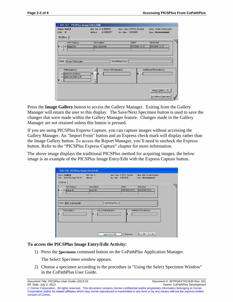
The following is an example of the PICSPlus Image Entry/Edit window.
Page 2-2 of 6 Accessing PICSPlus From CoPathPlus
Document Title: PICSPlus User Guide v2013.01 Document #: 30TRGEXT021635 Rev: 001 Eff. Date: July 2, 2013 Owner: CoPathPlus Development
Cerner Corporation. All rights reserved. This document contains Cerner confidential and/or proprietary information belonging to Cerner Corporation and/or its related affiliates which may not be reproduced or transmitted in any form or by any means without the express written consent of Cerner.
Press the Image Gallery button to access the Gallery Manager. Exiting from the Gallery
Manager will return the user to this display. The Save/Next Specimen button is used to save the
changes that were made within the Gallery Manager feature. Changes made in the Gallery
Manager are not retained unless this button is pressed.
If you are using PICSPlus Express Capture, you can capture images without accessing the
Gallery Manager. An "Import From" button and an Express check mark will display rather than
the Image Gallery button. To access the Report Manager, you’ll need to uncheck the Express
button. Refer to the “PICSPlus Express Capture" chapter for more information.
The above image displays the traditional PICSPlus method for acquiring images, the below
image is an example of the PICSPlus Image Entry/Edit with the Express Capture button.
To access the PICSPlus Image Entry/Edit Activity:
1) Press the Specimens command button on the CoPathPlus Application Manager.
The Select Specimen window appears.
2) Choose a specimen according to the procedure in "Using the Select Specimen Window"
in the CoPathPlus User Guide.

Accessing PICSPlus From CoPathPlus Page 2-3 of 6
Document Title: PICSPlus User Guide v2013.01 Document #: 30TRGEXT021635 Rev: 001 Eff. Date: July 2, 2013 Owner: CoPathPlus Development
Cerner Corporation. All rights reserved. This document contains Cerner confidential and/or proprietary information belonging to Cerner Corporation and/or its related affiliates which may not be reproduced or transmitted in any form or by any means without the express written consent of Cerner.
3) Select PICSPlus Image Entry/Edit in the Activity field on that window.
Note: PICSPlus Image Entry/Edit will only appear in the Activity field if a valid form sequence has been
assigned to the selected Specimen Class. Refer to "CoPathPlus PICSPlus Integration Activities" for more
information.
4) Press OK. The PICSPlus Image Entry/Edit window appears.
TIP! You can also access the PICSPlus Image Entry/Edit activity by selecting File > Browse Items or by placing it
in your Personal Menu and double-clicking on it from there.
PICSPlus Report Image Select
The PICSPlus Report Image Select Activity allows you to access the Report Manager for the
selected specimen. From the Report Manger, you can:
View the Report Gallery
Select/Unselect Images to be placed on the reports
Run the Report Gallery Review
You can also do many of the tasks available in the Gallery Manager:
Import Images from a file
Export Images from Image Gallery to a file
Import Images from TWAIN
Import Images from the Matrox Acquisition Manager
Import Images from the Clipboard
Review/Modify parameters
Open the PICSPlus View Manager
When accessing PICSPlus Report Image Select, the system will first prompt for the associated
report. Highlight the report you are working with and press OK. Images assigned to the report
during this session will be associated to the selected report.
The PICSPlus Report Image Select window will then be presented and also displays information
pertaining to the selected specimen. The information displayed is "grayed out" to indicate that
the specimen data is not editable on this form sequence. Scroll bars are active allowing all multi-

Page 2-4 of 6 Accessing PICSPlus From CoPathPlus
Document Title: PICSPlus User Guide v2013.01 Document #: 30TRGEXT021635 Rev: 001 Eff. Date: July 2, 2013 Owner: CoPathPlus Development
Cerner Corporation. All rights reserved. This document contains Cerner confidential and/or proprietary information belonging to Cerner Corporation and/or its related affiliates which may not be reproduced or transmitted in any form or by any means without the express written consent of Cerner.
instance information to be viewed. The following is an example of the PICSPlus Report Image
Select window.
Press the Select Images button to access the PICSPlus Report Manager. Exiting from the Report
Manager will return the user to this display. The Save/Next Specimen button is used to save the
changes that were made within the Report Manager. Changes made in the Report Manager are
not retained unless this button is pressed.
If you are using the PICSPlus Express Capture button, you can capture images without accessing
the Report Manager. An "Import From" button and an Express check mark will display rather
than the Select Images button. To access the Report Manager, you’ll need to uncheck the
Express button. Refer to the "PICSPlus Express Capture" chapter for more information.
Once a report is signed out, the PICSPlus Report Image Select feature can only be used for
viewing and export purposes. The only option available on the Attachments menu is the Export
to File option. The Image Viewer will show the Info tab for all report images, both images
included on the report and images that are not. No modifications, additions, or deletions can be
made to images in this feature.
To access the PICSPlus Report Image Select Activity:
1) Press the Specimens command button on the CoPathPlus Application Manager.
The Select Specimen window appears.
2) Choose a specimen according to the procedure in "Using the Select Specimen Window"
in the CoPathPlus User Guide.
3) Select PICSPlus Report Image Select in the Activity field on that window.
Note: PICSPlus Report Image Select will only appear in the Activity field if a valid form sequence has
been assigned to the selected Specimen Class. Refer to "CoPathPlus PICSPlus Integration Activities" for
more information.
4) Press OK. The Select a Report pop-up window appears.
5) Chose the report from the list and click OK. The PICSPlus Report Image Select window
appears.
Accessing PICSPlus From CoPathPlus Page 2-5 of 6
Document Title: PICSPlus User Guide v2013.01 Document #: 30TRGEXT021635 Rev: 001 Eff. Date: July 2, 2013 Owner: CoPathPlus Development
Cerner Corporation. All rights reserved. This document contains Cerner confidential and/or proprietary information belonging to Cerner Corporation and/or its related affiliates which may not be reproduced or transmitted in any form or by any means without the express written consent of Cerner.
TIP! You can also access the PICSPlus Report Image Select activity by selecting File > Browse Items or by placing
it in your Personal Menu and double-clicking on it from there.
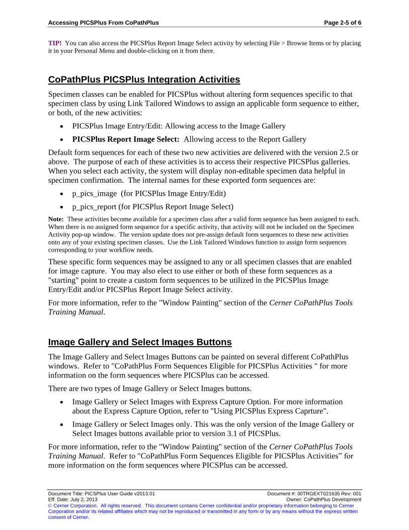
CoPathPlus PICSPlus Integration Activities
Specimen classes can be enabled for PICSPlus without altering form sequences specific to that
specimen class by using Link Tailored Windows to assign an applicable form sequence to either,
or both, of the new activities:
PICSPlus Image Entry/Edit: Allowing access to the Image Gallery
PICSPlus Report Image Select: Allowing access to the Report Gallery
Default form sequences for each of these two new activities are delivered with the version 2.5 or
above. The purpose of each of these activities is to access their respective PICSPlus galleries.
When you select each activity, the system will display non-editable specimen data helpful in
specimen confirmation. The internal names for these exported form sequences are:
p_pics_image (for PICSPlus Image Entry/Edit)
p_pics_report (for PICSPlus Report Image Select)
Note: These activities become available for a specimen class after a valid form sequence has been assigned to each.
When there is no assigned form sequence for a specific activity, that activity will not be included on the Specimen
Activity pop-up window. The version update does not pre-assign default form sequences to these new activities
onto any of your existing specimen classes. Use the Link Tailored Windows function to assign form sequences
corresponding to your workflow needs.
These specific form sequences may be assigned to any or all specimen classes that are enabled
for image capture. You may also elect to use either or both of these form sequences as a
"starting" point to create a custom form sequences to be utilized in the PICSPlus Image
Entry/Edit and/or PICSPlus Report Image Select activity.
For more information, refer to the "Window Painting" section of the Cerner CoPathPlus Tools
Training Manual.
Image Gallery and Select Images Buttons
The Image Gallery and Select Images Buttons can be painted on several different CoPathPlus
windows. Refer to "CoPathPlus Form Sequences Eligible for PICSPlus Activities " for more
information on the form sequences where PICSPlus can be accessed.
There are two types of Image Gallery or Select Images buttons.
Image Gallery or Select Images with Express Capture Option. For more information
about the Express Capture Option, refer to "Using PICSPlus Express Caprture".
Image Gallery or Select Images only. This was the only version of the Image Gallery or
Select Images buttons available prior to version 3.1 of PICSPlus.
For more information, refer to the "Window Painting" section of the Cerner CoPathPlus Tools
Training Manual. Refer to "CoPathPlus Form Sequences Eligible for PICSPlus Activities” for
more information on the form sequences where PICSPlus can be accessed.

Page 2-6 of 6 Accessing PICSPlus From CoPathPlus
Document Title: PICSPlus User Guide v2013.01 Document #: 30TRGEXT021635 Rev: 001 Eff. Date: July 2, 2013 Owner: CoPathPlus Development
Cerner Corporation. All rights reserved. This document contains Cerner confidential and/or proprietary information belonging to Cerner Corporation and/or its related affiliates which may not be reproduced or transmitted in any form or by any means without the express written consent of Cerner.
CoPathPlus Form Sequences Eligible for PICSPlus Activities
Each of the integrated PICSPlus buttons is eligible to be placed on certain windows classes in
CoPathPlus
The following CoPathPlus Form Sequences are eligible for PICSPlus activities:
Accession Entry/Edit
Gross Description Entry/Edit
Final Diagnosis Entry/Edit
Hot Seat Diagnosis Entry/Edit
Signout (Electronic)
Cytology Results Entry/Edit (Cytotech)
Cytology Results Entry/Edit (Pathologist)
Pathologist Console
Procedure/Addendum Entry/Edit
Post-Signout Edit
Signout (Manual)
The Image Gallery Button, which invokes the PICSPlus Gallery Manager, is eligible to be
included on the following windows:
Accession Entry/Edit
Gross Description Entry/Edit
Final Diagnosis Entry/Edit
Hot Seat Diagnosis Entry/Edit
Signout (Electronic)
Cytology Results Entry/Edit (Cytotech)
Cytology Results Entry/Edit (Pathologist)
Pathologist Console
Procedure/Addendum Entry/Edit
Post-Signout Edit
Signout (Manual)
Inquiry
The Select Images Button, which invokes the PICSPlus Reports Manager, is eligible to be
included on the following windows:
Signout (Electronic)
Signout (Manual)
Refer to the CoPathPlus User Guide for information on accessing the above windows.

Using the PICSPlus Gallery Manager Page 3-1 of 23
Document Title: PICSPlus User Guide v2013.01 Document #: 30TRGEXT021635 Rev: 001 Eff. Date: July 2, 2013 Owner: CoPathPlus Development
Cerner Corporation. All rights reserved. This document contains Cerner confidential and/or proprietary information belonging to Cerner Corporation and/or its related affiliates which may not be reproduced or transmitted in any form or by any means without the express written consent of Cerner.
Chapter 3: Using the PICSPlus Gallery Manager
When you click the Image Gallery button on a CoPathPlus activity window, the PICSPlus Gallery
Manager opens. Refer to "Accessing PICSPlus from CoPathPlus" for information on the
windows.
The PICSPlus Gallery Manager has an Image Gallery that provides the ability to view the images
that have been previously capture or imported into the active patient record. The Image Gallery
displays thumbnail images of the images that have been previously captured. If no image has
been previously acquired, the Image Gallery will be empty.
The following illustration is an example of the PICSPlus Gallery Manager.
The PICSPlus Gallery Manager contains the following component areas:
Menu Bar
Image Gallery
Parameters for Selected Item in Image Gallery
Linked to Reports

Page 3-2 of 23 Using the PICSPlus Gallery Manager
Document Title: PICSPlus User Guide v2013.01 Document #: 30TRGEXT021635 Rev: 001 Eff. Date: July 2, 2013 Owner: CoPathPlus Development
Cerner Corporation. All rights reserved. This document contains Cerner confidential and/or proprietary information belonging to Cerner Corporation and/or its related affiliates which may not be reproduced or transmitted in any form or by any means without the express written consent of Cerner.
Image Gallery Review Button
Import from Button
Task Buttons
The PICSPlus Gallery Manager can be configured to use PICSPlus Express Capture. If the
Express check mark appears on the PICSPlus Gallery Manager, your system has been configured
to use this method. Refer to "PICSPlus Express Capture" for more information.
PICSPlus Gallery Manager Menu Bar
The PICSPlus Gallery Manager Menu Bar consists of the following menus. Each menu has its
own set of commands.
File Menu
Edit Menu
Attachments Menu
Options Menu
PICSPlus Gallery Manager File Menu
The File menu on the PICSPlus Gallery Manager displays a drop-down with one item: Close.
Selecting this closes the PICSPlus Gallery Manager and returns you to CoPathPlus.
PICSPlus Gallery Manager Edit Menu
The Edit menu on the PICSPlus Gallery Manager displays a drop-down with the following
items:
Delete Selected. Deletes the images that have been selected. To select a single image,
move the mouse cursor over the image and depress the left mouse button. To select
several, but not all, images hold the CTRL key on the keyboard down and depress the left
mouse button on top of each image that you want to select. As you select the image the
border of the image will become colored as opposed to gray (the unselected color).
Delete Selected may also be invoked by pressing the Del key.
Select All. Selects all the images in the gallery. To deselect all images, click on an empty
space in the gallery. . Selected All also be invoked by the keyboard strokes of Control +
A.
Using the PICSPlus Gallery Manager Page 3-3 of 23
Document Title: PICSPlus User Guide v2013.01 Document #: 30TRGEXT021635 Rev: 001 Eff. Date: July 2, 2013 Owner: CoPathPlus Development
Cerner Corporation. All rights reserved. This document contains Cerner confidential and/or proprietary information belonging to Cerner Corporation and/or its related affiliates which may not be reproduced or transmitted in any form or by any means without the express written consent of Cerner.
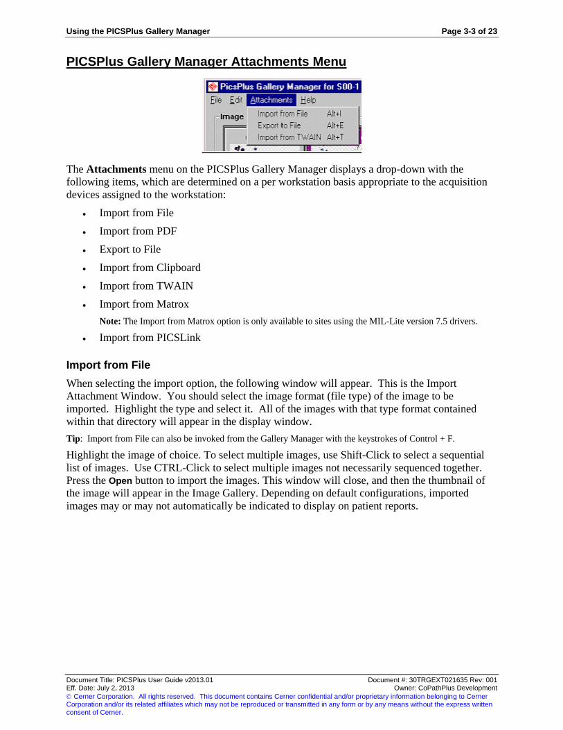
PICSPlus Gallery Manager Attachments Menu
The Attachments menu on the PICSPlus Gallery Manager displays a drop-down with the
following items, which are determined on a per workstation basis appropriate to the acquisition
devices assigned to the workstation:
Import from File
Import from PDF
Export to File
Import from Clipboard
Import from TWAIN
Import from Matrox
Note: The Import from Matrox option is only available to sites using the MIL-Lite version 7.5 drivers.
Import from PICSLink
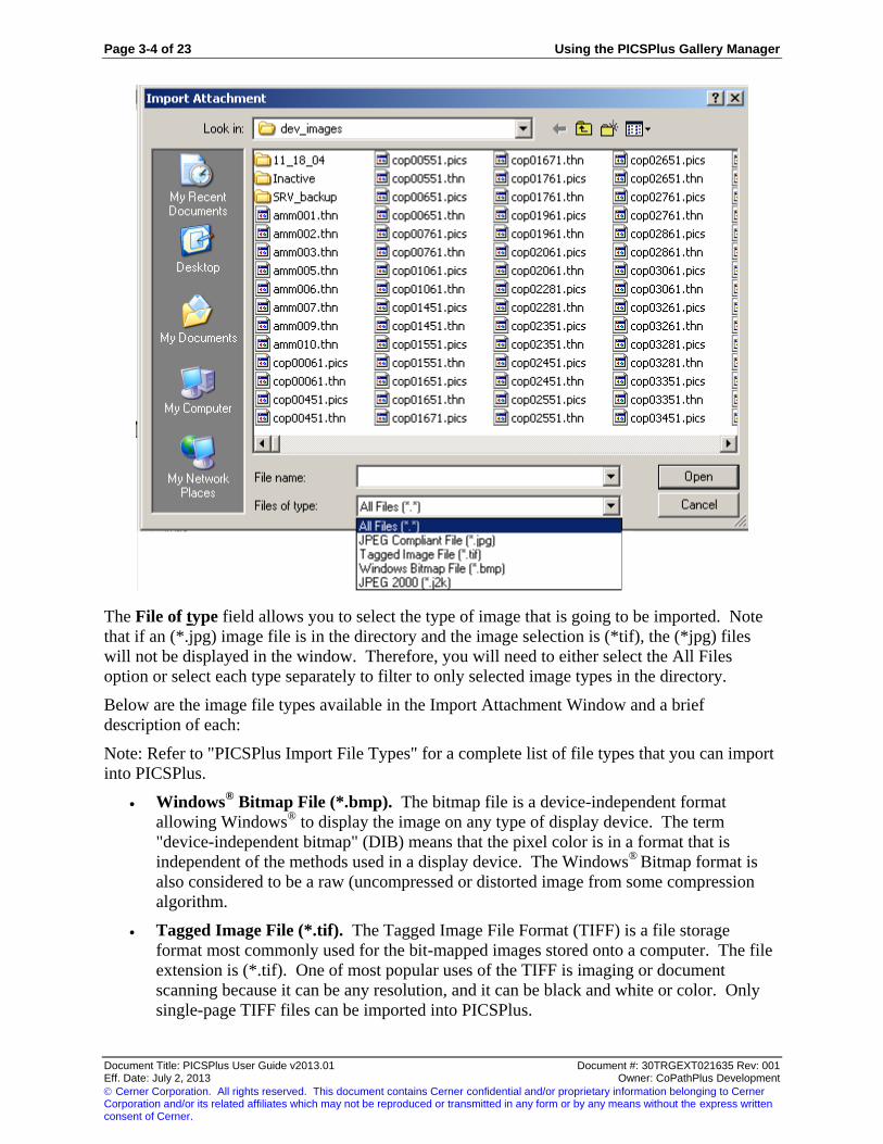
Import from File
When selecting the import option, the following window will appear. This is the Import
Attachment Window. You should select the image format (file type) of the image to be
imported. Highlight the type and select it. All of the images with that type format contained
within that directory will appear in the display window.
Tip: Import from File can also be invoked from the Gallery Manager with the keystrokes of Control + F.
Highlight the image of choice. To select multiple images, use Shift-Click to select a sequential
list of images. Use CTRL-Click to select multiple images not necessarily sequenced together.
Press the Open button to import the images. This window will close, and then the thumbnail of
the image will appear in the Image Gallery. Depending on default configurations, imported
images may or may not automatically be indicated to display on patient reports.
Page 3-4 of 23 Using the PICSPlus Gallery Manager
Document Title: PICSPlus User Guide v2013.01 Document #: 30TRGEXT021635 Rev: 001 Eff. Date: July 2, 2013 Owner: CoPathPlus Development
Cerner Corporation. All rights reserved. This document contains Cerner confidential and/or proprietary information belonging to Cerner Corporation and/or its related affiliates which may not be reproduced or transmitted in any form or by any means without the express written consent of Cerner.
The File of type field allows you to select the type of image that is going to be imported. Note
that if an (*.jpg) image file is in the directory and the image selection is (*tif), the (*jpg) files
will not be displayed in the window. Therefore, you will need to either select the All Files
option or select each type separately to filter to only selected image types in the directory.
Below are the image file types available in the Import Attachment Window and a brief
description of each:
Note: Refer to "PICSPlus Import File Types" for a complete list of file types that you can import
into PICSPlus.
Windows® Bitmap File (*.bmp). The bitmap file is a device-independent format
allowing Windows®
to display the image on any type of display device. The term
"device-independent bitmap" (DIB) means that the pixel color is in a format that is
independent of the methods used in a display device. The Windows®
Bitmap format is
also considered to be a raw (uncompressed or distorted image from some compression
algorithm.
Tagged Image File (*.tif). The Tagged Image File Format (TIFF) is a file storage
format most commonly used for the bit-mapped images stored onto a computer. The file
extension is (*.tif). One of most popular uses of the TIFF is imaging or document
scanning because it can be any resolution, and it can be black and white or color. Only
single-page TIFF files can be imported into PICSPlus.

Using the PICSPlus Gallery Manager Page 3-5 of 23
Document Title: PICSPlus User Guide v2013.01 Document #: 30TRGEXT021635 Rev: 001 Eff. Date: July 2, 2013 Owner: CoPathPlus Development
Cerner Corporation. All rights reserved. This document contains Cerner confidential and/or proprietary information belonging to Cerner Corporation and/or its related affiliates which may not be reproduced or transmitted in any form or by any means without the express written consent of Cerner.
Note: When possible, it is recommended that non-color images be obtained as grayscale images rather than
black and white images. The Grayscale mode should be used to scan medium or low quality printed
documents, hand-written documents (e.g. requisition forms) and faxes. You can also use this mode to save
space when scanning documents for which picture color is not important. Refer to documentation from
your scanning or other device manufacturer for configuration information.
JPEG Compliant File (*.jpg). This format takes advantage of the human vision to
interpolate information that is not present. It compresses images using a discrete cosine
transform algorithm. It eliminates redundancy of pixels that meet specific frequency
criteria. JPEG stands for Joint Picture Expert Group. This was the name adopted by the
original imaging experts. This group created the compression algorithms standards.
JPEG 2000 (*.j2k). This format was developed to provide low bit rate operation with
rate-distortion and subjective image quality performance superior to existing standards,
without sacrificing performance at other points in the rate-distortion spectrum. This is
the format PICSPlus uses to store images.
PDF. Refer to "Import from PDF" for more information.
Note: When creating diagrams or other image files that will be embedded into reports, it is advised that the images
are created using a graphic editing tool that has 24-bit color. The image pixel resolution should be created at 640 x
480 at 96 dpi. Larger dpi’s will appear smaller on the report than the designated area and smaller dpi’s will appear
pixelated.
PICSPlus Import File Types
Thirty-four file formats are supported in PICSPlus for importing. All of these images are
converted to JPEG 2000 format once imported. The list of PICSPlus eligible file formats now
includes the following formats:
Amiga (*.iff) Portable Pixelmap (*ppm)
Brooktrout Fax (*.brk, *.301) SciTex Continuous Tone (*.sct, *.ct)
CALS Raster (*.cal, *.cals) SGI Image File (*.rgb, *.bw, *.rgba, *.sgi)
CompuServe Graphics Interchange (*.gif) Sun Raster Image (*.ras)
Deluxe Paint (*.lbm) Tagged Image File Format (*.tif, *.tiff)
Dr. Halo (*.cut) True Vision Targa (*.tga)
Encapsulated Post Script (*.eps, *.ps – monochrome
with preview only)
Windows Clipboard (*.clp)
GEM Paint (*.img) Windows Enhanced Meta File (*.emf)
JPEG (*.jpg, *.jif, *.jpeg) Window Metafile (*wmf – save bimpap data only)
JPEG 2000 (*.jp2, *.j2c, *.j2k, *.jpc, *.jpx) WindowsOrCompuServeRLE (*.rle)
Macintosh PICT (*.pct) Windows or OS2 Bitmap (*.bmp)
MacPaint (*.mac) Windows or OS2 DIB (.dib)
NCR G4 (*ncr) Wireless Bitmap (*wbmp)
Photoshop (*.psd) Xwindows Bitmap (*.xbm, *.bm)
Portable bitmap (*.pbm) XWIndows Dump (*.xwd, *.wd)
Protable Graymap (*.pgm) XWindowsPixmap (*.xpm)
Portable Network Graphics (*.png) ZSoft Paintbrush (*.pcx)
Files can only be exported in JPEG, BMP, TIFF and JPEG 2000 formats.

Page 3-6 of 23 Using the PICSPlus Gallery Manager
Document Title: PICSPlus User Guide v2013.01 Document #: 30TRGEXT021635 Rev: 001 Eff. Date: July 2, 2013 Owner: CoPathPlus Development
Cerner Corporation. All rights reserved. This document contains Cerner confidential and/or proprietary information belonging to Cerner Corporation and/or its related affiliates which may not be reproduced or transmitted in any form or by any means without the express written consent of Cerner.
Import from PDF
PICSPlus now offers the ability to convert and then import files that originate as electronic PDF
files. Import of PDF files requires that the file be rasterized or converted to an image file. When
a multi-page PDF is rasterized, each page will be converted, stored, and presented as a separate
image in the Image Gallery. Files stored as images files are not re-converted to PDFs if they are
exported.
Set the preferred resolution value in the "Resolution for PDF conversion into the raster image
(pixels/Inch)" field before acquiring a PDF image. The resolution of the PDF is set according to
this value when the PDF is acquired. The resolution cannot be changed on an already acquired
file. If you need an imported file to be retained at a different resolution, delete the originally
acquired file. Change the value in the "Resolution for PDF conversion into the raster image
(pixels/Inch) field" setting and then re-acquire that PDF.
Increasing the resolution value will provide better conversion quality but will also increase file
size and conversion time. Resolution cannot improve quality of the original document.
Experiment to determine the optimal value for your documents and set the default value
accordingly.
To modify the default resolution, press on the up arrow or down arrow spin control. Resolution
levels will change in increments of 50 and range between 100 and 600.
When the rasterization technology is used for saving a consult report to a case, you may wish to
include this image in a fairly large size on your patient report. As with other images, define an
attachment type with appropriate dimensions and set it to be allowed to print on patient reports.
When defining an image size, remember that the image must fit within the header, footer, and
side margins defined for your patient report template(s). In addition, you must also allow room
for the image title to print beneath the report. In circumstances where the defined height and
width of your image size in the Attachment Type Dictionary is not proportional to the image
itself, the image will resize itself to maintain proportionality. Do not define a image that is too
large to fit within your patient report borders. For example, for a report template that uses 1.2
inch header, footer, right margin, and left margin, a rasterized image of a PDF that was formerly
11 x 8.5 might be sized to 9.5 x 7.35. Perform your own experiments with rasterized images
that are both "busy" and "fairly light" on content to determine what works best for your lab.
Note: The Resolution for PDF Conversion field affects quality of the image (formerly the PDF) that is retained
within CoPathPlus. The Print Quality field in the Attachment Type Dictionary affects print quality of a specific
attachment type when it is printed on a patient report generated by the site’s text editor. Consider both your specific
requirements in image retention and report display, and then balance these needs against the required conversion
time, storage, and printer resources when setting these two parameters. For example, you might opt to retain the
image at a fairly high resolution, but realize you can set a relatively low print quality and still have an acceptable
report display. For formatted patient reports sent via a MIME or PDF interface that do not already use an already
created PDF, interface configuration determine image resolution within the patient report.
Export to File
Any images assigned to a CoPathPlus specimen may also be exported. Image can be exported at
a publishing quality if the camera used to take the image supported an adequate pixel count. To
verify that the image is publishing quality, you can use the PICSPlus Resolutions Calculator,
available from the Options menu. Refer to "PICSPlus Resolutions Calculator" for more
information

Using the PICSPlus Gallery Manager Page 3-7 of 23
Document Title: PICSPlus User Guide v2013.01 Document #: 30TRGEXT021635 Rev: 001 Eff. Date: July 2, 2013 Owner: CoPathPlus Development
Cerner Corporation. All rights reserved. This document contains Cerner confidential and/or proprietary information belonging to Cerner Corporation and/or its related affiliates which may not be reproduced or transmitted in any form or by any means without the express written consent of Cerner.
To Export an Image:
1) Access the Image Gallery.
2) Select the image(s) you want to export. If you are selecting multiple images, hold down
the CTRL key when selecting images in a list and CTRL + Shift when selecting non-
sequential images.
3) Select Export to File from the File menu or press CTRL + E.
The Export Attachment window appears.
4) Navigate to the drive and folder where the images should be saved. Enter the file name
and select the format (file type) of the image(s) to be exported. If you are exporting
multiple files, enter a prefix that will be applied as the first part of the name of all images
selected. Click Save. The system will provide a warning regarding imaging naming,
relating that all images will receive the same prefix that will then be followed by a dash
and a sequence number should the user continue with the export. Click OK to continue
with the export.
After saving the images, the Export Attachments Window will close and return to the Image.
Import from Clipboard
You can directly images from a variety of image editors and viewers, including the web browser
using the Import from Clipboard option. This option will import an image that you have copied
to the Clipboard into PICSPlus. The Clipboard is the memory area (buffer) where data is stored
temporarily before being copied to another location. For example, if you copy a picture from a
web page and then use the Import from Clipboard option, you can paste the image into PICSPlus.
To import an image from the Clipboard, copy the image from the application where the image is
located. To copy an image from a web page using Internet Explorer, right-click the mouse over
the image and select Copy from the menu that appears. To copy images from other applications;
refer to the application’s user documentation. After you have copied the image, switch to the
PICSPlus Gallery Manager and select the Import from Clipboard option. The image will then
appear in the Gallery Manager.
Tip: Import from Clipboard can also be invoked from the Gallery Manager with the keystrokes of Control + B.
Page 3-8 of 23 Using the PICSPlus Gallery Manager
Document Title: PICSPlus User Guide v2013.01 Document #: 30TRGEXT021635 Rev: 001 Eff. Date: July 2, 2013 Owner: CoPathPlus Development
Cerner Corporation. All rights reserved. This document contains Cerner confidential and/or proprietary information belonging to Cerner Corporation and/or its related affiliates which may not be reproduced or transmitted in any form or by any means without the express written consent of Cerner.
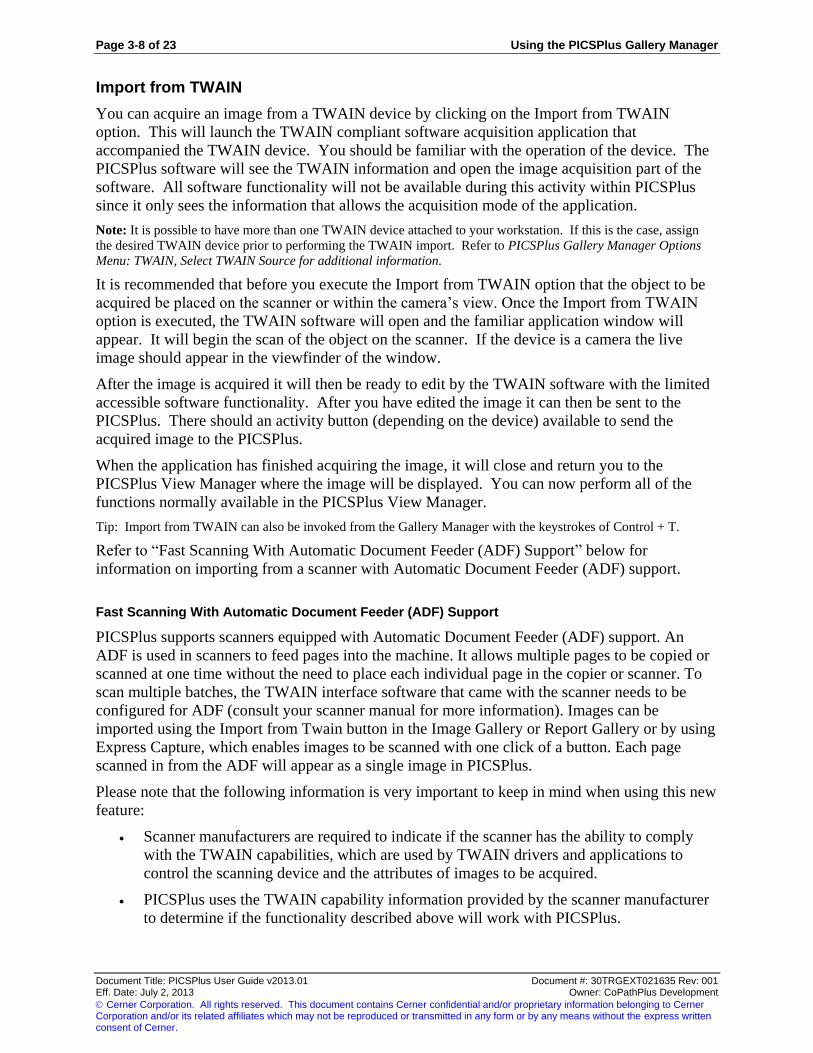
Import from TWAIN
You can acquire an image from a TWAIN device by clicking on the Import from TWAIN
option. This will launch the TWAIN compliant software acquisition application that
accompanied the TWAIN device. You should be familiar with the operation of the device. The
PICSPlus software will see the TWAIN information and open the image acquisition part of the
software. All software functionality will not be available during this activity within PICSPlus
since it only sees the information that allows the acquisition mode of the application.
Note: It is possible to have more than one TWAIN device attached to your workstation. If this is the case, assign
the desired TWAIN device prior to performing the TWAIN import. Refer to PICSPlus Gallery Manager Options
Menu: TWAIN, Select TWAIN Source for additional information.
It is recommended that before you execute the Import from TWAIN option that the object to be
acquired be placed on the scanner or within the camera’s view. Once the Import from TWAIN
option is executed, the TWAIN software will open and the familiar application window will
appear. It will begin the scan of the object on the scanner. If the device is a camera the live
image should appear in the viewfinder of the window.
After the image is acquired it will then be ready to edit by the TWAIN software with the limited
accessible software functionality. After you have edited the image it can then be sent to the
PICSPlus. There should an activity button (depending on the device) available to send the
acquired image to the PICSPlus.
When the application has finished acquiring the image, it will close and return you to the
PICSPlus View Manager where the image will be displayed. You can now perform all of the
functions normally available in the PICSPlus View Manager.
Tip: Import from TWAIN can also be invoked from the Gallery Manager with the keystrokes of Control + T.
Refer to “Fast Scanning With Automatic Document Feeder (ADF) Support” below for
information on importing from a scanner with Automatic Document Feeder (ADF) support.
Fast Scanning With Automatic Document Feeder (ADF) Support
PICSPlus supports scanners equipped with Automatic Document Feeder (ADF) support. An
ADF is used in scanners to feed pages into the machine. It allows multiple pages to be copied or
scanned at one time without the need to place each individual page in the copier or scanner. To
scan multiple batches, the TWAIN interface software that came with the scanner needs to be
configured for ADF (consult your scanner manual for more information). Images can be
imported using the Import from Twain button in the Image Gallery or Report Gallery or by using
Express Capture, which enables images to be scanned with one click of a button. Each page
scanned in from the ADF will appear as a single image in PICSPlus.
Please note that the following information is very important to keep in mind when using this new
feature:
Scanner manufacturers are required to indicate if the scanner has the ability to comply
with the TWAIN capabilities, which are used by TWAIN drivers and applications to
control the scanning device and the attributes of images to be acquired.
PICSPlus uses the TWAIN capability information provided by the scanner manufacturer
to determine if the functionality described above will work with PICSPlus.

Using the PICSPlus Gallery Manager Page 3-9 of 23
Document Title: PICSPlus User Guide v2013.01 Document #: 30TRGEXT021635 Rev: 001 Eff. Date: July 2, 2013 Owner: CoPathPlus Development
Cerner Corporation. All rights reserved. This document contains Cerner confidential and/or proprietary information belonging to Cerner Corporation and/or its related affiliates which may not be reproduced or transmitted in any form or by any means without the express written consent of Cerner.
After considerable testing of numerous scanners, we have discovered that the information
about the TWAIN capability provided by the scanner manufacturer is not always correct.
In these situations, PICSPlus will ignore the functionality if it does not work with the
scanner, for example if the scanner is not capable of hiding the user interface it will still
display, even if you have unchecked “Show User Interface”. In these situations, please
contact the scanner manufacturer for more information.
Import from Matrox
When using the PICSPlus Acquisition Manager associated Matrox, the Matrox Acquisition
Manager may be invoked via the following methods:
When a workstation has defined Matrox acquisition as the default acquisition method,
click on the Import from Matrox button. (Refer to "Default Import Action" for more
information.)
The following methods to invoke Matrox Import can be used whether the Matrox is the
default acquisition method or it the workstation is only used for occasional Matrox
acquisitions, thus the default acquisition method is defined to be a different import type:
Click on the Attachments menu and then select the Import from Matrox Item
Simultaneously press the CTRL and the M key.
The Matrox Acquisition Manager will be displayed after any of these methods are used. The
following is an example of the Matrox Acquisition Manager
This window is used to acquire (capture) the image. Position the display on your Matrox devices
to the appropriate position and acquire the image. The image is captured either by clicking on

Page 3-10 of 23 Using the PICSPlus Gallery Manager
Document Title: PICSPlus User Guide v2013.01 Document #: 30TRGEXT021635 Rev: 001 Eff. Date: July 2, 2013 Owner: CoPathPlus Development
Cerner Corporation. All rights reserved. This document contains Cerner confidential and/or proprietary information belonging to Cerner Corporation and/or its related affiliates which may not be reproduced or transmitted in any form or by any means without the express written consent of Cerner.
the Acquire button, pressing Alt + Q or simply pressing the Enter key since the Acquire button is
the default key for the screen.
Following image acquisition, the screen display will either return to the Image Gallery or it will
open the PICSPlus View Manager, where annotations may be made.
The Attachments drop-down menu now also supports the import of image from the PICSLink.
An image from an imaging device interfaced to CoPathPlus can be imported via this menu or via
use of CTRL+ P.
When using an imaging device interfaced to CoPathPlus, PICSLink may be invoked via the
following methods:
When a workstation has defined PICSLink acquisition as the default acquisition method,
click on the Import from PICSLink button. (Refer to "Default Import Action" for more
information.)
The following methods to invoke PICSLink Import can be used whether the PICSLink is
the default acquisition method or it the workstation is only used for occasional PICSLink
acquisitions, thus the default acquisition method is defined to be a different import type:
Click on the Attachments menu and then select the Import from PICSLink Item
Simultaneously press the CTRL and the P key.
Following image acquisition, the screen display will either return to the Image Gallery or it will
open the PICSPlus View Manager, where annotations may be made.
PICSPlus Gallery Manager Options Menu
The Options menu on the PICSPlus Gallery Manager displays a drop-down with two items:
Image Viewer
Default Import Action
Default Import Template
Resolutions Calculator
PICSLink Devices
TWAIN
Image Viewer
The Image Viewer menu display contains the following item:
Load with maximized view
This option lets you select to open images in the PICSPlus View Manager by default in
Maximize View or in Normal View. If you select this option and place a check mark next to it,
as displayed in the illustration below, when you open images from the Gallery Manager, the
images will open in Maximize View. If there is no check mark, the images will open in Normal
View.

Using the PICSPlus Gallery Manager Page 3-11 of 23
Document Title: PICSPlus User Guide v2013.01 Document #: 30TRGEXT021635 Rev: 001 Eff. Date: July 2, 2013 Owner: CoPathPlus Development
Cerner Corporation. All rights reserved. This document contains Cerner confidential and/or proprietary information belonging to Cerner Corporation and/or its related affiliates which may not be reproduced or transmitted in any form or by any means without the express written consent of Cerner.
Default Import Action
The Import Action default is maintained on a per workstation basis. The acquisition method
(File, Clipboard, TWAIN, or Matrox) that is displayed at the time the Image Gallery is closed
will be the one automatically displayed when the gallery is re-accessed.
When using PICSPlus Express Capture, you must set the default import action
Specific Default Import Action menu display will vary at workstations. A full Default Import
Action menu would include the following:
Import from File
Import from Clipboard
Import from TWAIN
Import From Matrox
Import From PICSLink
To define the default import action for the workstation, make the following selections.
1) Select the Options Menu from the Image Gallery
2) Select Default Import Action. A menu similar to the following appears.
3) Click on the appropriate "Import Action" option. A check mark will appear to the left of
the selected option.
Default Import Template
The Default Import Template menu display is determined on a per workstation basis appropriate
to the acquisition devices assigned to the workstation. Workstation specific acquisition devices
are defined in the Workstation Setup. The template default may be defined based on a
combination of image acquisition method (Import, TWAIN, or Matrox). Once a template is
defined for an acquisition method on a specific workstation, that specific template is retained as
the default for that workstation for each specific acquisition method until the user specifically
modifies it.
Specific option menu display will vary at workstations. A full Options menu would include the
following:

Page 3-12 of 23 Using the PICSPlus Gallery Manager
Document Title: PICSPlus User Guide v2013.01 Document #: 30TRGEXT021635 Rev: 001 Eff. Date: July 2, 2013 Owner: CoPathPlus Development
Cerner Corporation. All rights reserved. This document contains Cerner confidential and/or proprietary information belonging to Cerner Corporation and/or its related affiliates which may not be reproduced or transmitted in any form or by any means without the express written consent of Cerner.
Import from File
Import from Clipboard
Import from TWAIN
Import From Matrox
Import from PICSLink
To define the appropriate default template for the workstation, make the following
selections.
1) Select the Options Menu from the Image Gallery
2) Select Default Import Template.
3) Select the appropriate "Import from" option. The following pop-up window will appear.
4) Use the drop-down to select the desired template from the PICSPlus Template
Dictionary.
5) Click Save to make the choice the default for this workstation.
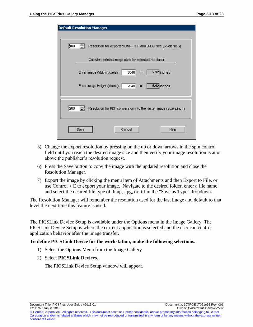
PICSPlus Resolutions Calculator
Publishers may request images be of specific minimal resolutions and compressions. The
resolution value will affects the printed image size. For example, a publisher may require that an
image be between four and six inches with a resolution of not less than 300 pixels per inch. The
Resolutions Calculator will allow you to ascertain the image size in inches when a specific
resolution is applied.
To determine whether your image may be exported at publishing quality and to prepare it
for export:
1) Select that image in the PICSPlus Image Manager or Report Manager.
2) Open the Image Viewer for that image and select the Info tab to see the height and width
of that image in pixels.
3) Return to the gallery to open the Resolution Manager from the Option dropdown menu or
press Control + Shift + S.
4) Enter the width and height in pixels into the fields provided.
Using the PICSPlus Gallery Manager Page 3-13 of 23
Document Title: PICSPlus User Guide v2013.01 Document #: 30TRGEXT021635 Rev: 001 Eff. Date: July 2, 2013 Owner: CoPathPlus Development
Cerner Corporation. All rights reserved. This document contains Cerner confidential and/or proprietary information belonging to Cerner Corporation and/or its related affiliates which may not be reproduced or transmitted in any form or by any means without the express written consent of Cerner.
5) Change the export resolution by pressing on the up or down arrows in the spin control
field until you reach the desired image size and then verify your image resolution is at or
above the publisher’s resolution request.
6) Press the Save button to copy the image with the updated resolution and close the
Resolution Manager.
7) Export the image by clicking the menu item of Attachments and then Export to File, or
use Control + E to export your image. Navigate to the desired folder, enter a file name
and select the desired file type of .bmp, .jpg, or .tif in the "Save as Type" dropdown.
The Resolution Manager will remember the resolution used for the last image and default to that
level the next time this feature is used.
The PICSLink Device Setup is available under the Options menu in the Image Gallery. The
PICSLink Device Setup is where the current application is selected and the user can control
application behavior after the image transfer.
To define PICSLink Device for the workstation, make the following selections.
1) Select the Options Menu from the Image Gallery
2) Select PICSLink Devices.
The PICSLink Device Setup window will appear.

Page 3-14 of 23 Using the PICSPlus Gallery Manager
Document Title: PICSPlus User Guide v2013.01 Document #: 30TRGEXT021635 Rev: 001 Eff. Date: July 2, 2013 Owner: CoPathPlus Development
Cerner Corporation. All rights reserved. This document contains Cerner confidential and/or proprietary information belonging to Cerner Corporation and/or its related affiliates which may not be reproduced or transmitted in any form or by any means without the express written consent of Cerner.
3) Enter the following fields:
Select Current PICSLink Device. Select a device from the drop-down menu. The
list of available devices is populated from the Imaging Device Type Dictionary.
EXE File Path. Click the Browse button to link to the EXE file for the imaging
device. PICSLink uses this connection to communicate with the imaging device.
User Name and Password. If required by the imaging device, enter a user name and
password so PICSLink can communicate with the imaging device.
After Data Transfer:
Close All Images in the Device Application. Select this option if you want the
image acquired through the image device to close after it has transferred to
PICSPlus. If you do not select this option, you will need to manually close the
images through the image device software.
Minimize the Device Application. Select this option if you want the window
displaying the imaging device software to minimize after the data has transferred
to PICSPlus.
4) Save the changes.

Using the PICSPlus Gallery Manager Page 3-15 of 23
Document Title: PICSPlus User Guide v2013.01 Document #: 30TRGEXT021635 Rev: 001 Eff. Date: July 2, 2013 Owner: CoPathPlus Development
Cerner Corporation. All rights reserved. This document contains Cerner confidential and/or proprietary information belonging to Cerner Corporation and/or its related affiliates which may not be reproduced or transmitted in any form or by any means without the express written consent of Cerner.
TWAIN
The TWAIN menu is used to allow definition of TWAIN parameters specific to the workstation.
Two options appear on the TWAIN Menu:
Multiple TWAIN Source Selection
Import from Clipboard
Show User Interface
Keep User Interface Open
Multiple TWAIN Source Selection
PICSPlus allows for image acquisition from more than one TWAIN source attached directly to
the same workstation.
When the Import from TWAIN feature is utilized under this circumstance, a Select Source
window will be presented. Highlight the desired source and then press the Select button.
TWAIN Force Buffered Memory Transfer
PICSPlus was designed to work with TWAIN Native data transfer. The TWAIN standard
stipulates that any device represented as TWAIN-compatible must support Native data transfer.
However, certain manufactures denote their devices as TWAIN compatible when Native data
transfer is not supported. While all TWAIN devices recommended by Cerner CoPathPlus use
Native data transfer, some clients wish to work with devices they owned before the PICSPlus
implementation that do not follow this specific standard.
Note: Use Force Buffered Memory Transfer switch on workstations that interact with TWAIN devices using
memory-buffered data transfer only. When the Force Buffered Memory Transfer option is selected, CoPathPlus
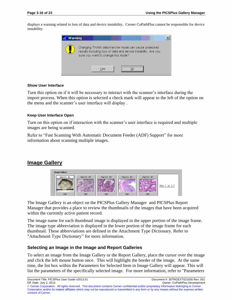
Page 3-16 of 23 Using the PICSPlus Gallery Manager
Document Title: PICSPlus User Guide v2013.01 Document #: 30TRGEXT021635 Rev: 001 Eff. Date: July 2, 2013 Owner: CoPathPlus Development
Cerner Corporation. All rights reserved. This document contains Cerner confidential and/or proprietary information belonging to Cerner Corporation and/or its related affiliates which may not be reproduced or transmitted in any form or by any means without the express written consent of Cerner.
displays a warning related to loss of data and device instability. Cerner CoPathPlus cannot be responsible for device
instability.
Show User Interface
Turn this option on if it will be necessary to interact with the scanner’s interface during the
import process. When this option is selected a check mark will appear to the left of the option on
the menu and the scanner’s user interface will display .
Keep User Interface Open
Turn on this option on if interaction with the scanner’s user interface is required and multiple
images are being scanned.
Refer to “Fast Scanning With Automatic Document Feeder (ADF) Support” for more
information about scanning multiple images.
Image Gallery
The Image Gallery is an object on the PICSPlus Gallery Manager and PICSPlus Report
Manager that provides a place to review the thumbnails of the images that have been acquired
within the currently active patient record.
The image name for each thumbnail image is displayed in the upper portion of the image frame.
The image type abbreviation is displayed in the lower portion of the image frame for each
thumbnail. These abbreviations are defined in the Attachment Type Dictionary. Refer to
"Attachment Type Dictionary” for more information.
Selecting an Image in the Image and Report Galleries
To select an image from the Image Gallery or the Report Gallery, place the cursor over the image
and click the left mouse button once. This will highlight the border of the image. At the same
time, the list box within the Parameters for Selected Item in Image Gallery will appear. This will
list the parameters of the specifically selected image. For more information, refer to "Parameters

Using the PICSPlus Gallery Manager Page 3-17 of 23
Document Title: PICSPlus User Guide v2013.01 Document #: 30TRGEXT021635 Rev: 001 Eff. Date: July 2, 2013 Owner: CoPathPlus Development
Cerner Corporation. All rights reserved. This document contains Cerner confidential and/or proprietary information belonging to Cerner Corporation and/or its related affiliates which may not be reproduced or transmitted in any form or by any means without the express written consent of Cerner.
for Selected Item in Image Gallery". To deselect an image, click on a different image to be
selected or click on an empty space in the Image Gallery.
The following illustration displays examples of thumbnails in selected and unselected state:
Note: You can also select an image in the Image Gallery and press the CTRL + L shortcut to open the PICSPlus
View Manager.
It is also possible to select multiple images by pressing the Shift or CTRL key in conjunction with
clicking the mouse. This is useful for exporting multiple images. Refer to "Image and Report
Gallery Keyboard and Mouse Shortcuts” for more information.
Note: If multiple images are selected, the Parameter data will not display in the Parameter List Box.
Image and Report Gallery Keyboard and Mouse Shortcuts
The following table displays the Keyboard and Mouse Shortcuts for the Image Gallery. These
shortcuts also apply to the Report Gallery.
Action Mouse Keyboard Mouse and Keyboard
Select single thumbnail Left-click Ctrl + space bar (If
thumbnail has focus
indicator)
Ctrl + Left-click
Unselect single thumbnail Left-click on
empty space
(unselect all
selected
thumbnails)
Ctrl + space bar (If
thumbnail has focus
indicator)
Shift + Left-click
Move focus indicator
without selecting thumbnail
N/A Ctrl + Arrow (Left, Right,
Up and Down) or Home
(End) to move to the first
N/A

Page 3-18 of 23 Using the PICSPlus Gallery Manager
Document Title: PICSPlus User Guide v2013.01 Document #: 30TRGEXT021635 Rev: 001 Eff. Date: July 2, 2013 Owner: CoPathPlus Development
Cerner Corporation. All rights reserved. This document contains Cerner confidential and/or proprietary information belonging to Cerner Corporation and/or its related affiliates which may not be reproduced or transmitted in any form or by any means without the express written consent of Cerner.
thumbnail or last thumbnail.
Select all thumbnails Right-click on any
place within the
Gallery and Left-
click on Select All
Menu Item.
Ctrl + A Select first
thumbnail and Shift
+ Left-click on last
thumbnail
Unselect all thumbnails Left-click on
empty space
Press Home (or End) and
after that Ctrl + space bar
Left-click on any
thumbnail and after
that Ctrl + space bar
Delete selected thumbnail
(thumbnails)
Right-click on any
place within the
Gallery and Left-
click on Delete
Selected Menu
Item.
Del N/A
Load PICSPlus Image
Viewer (Image Gallery
Only)
Double-click on
thumbnail
Ctrl + L N/A
Parameters for Selected Item in Image Gallery
This component of the PICSPlus Gallery Manager and Report Manager is a list box of the
parameters assigned to the selected image within the Image Gallery or Report Gallery. See the
figure below.
To select an image, place the cursor over the image and click the left mouse button once. This
will highlight the border of the image. At the same time, the list box within the Parameters for
Selected Item in Image Gallery will appear. This will list the parameters of the selected image.
There are two columns in this list: Name and Value. These values are either assigned by the user
or by the system, depending on the type of parameter. The names of the parameters are set-up in
the PICSPlus Template Dictionary. These parameters are attributes assigned to images. Some

Using the PICSPlus Gallery Manager Page 3-19 of 23
Document Title: PICSPlus User Guide v2013.01 Document #: 30TRGEXT021635 Rev: 001 Eff. Date: July 2, 2013 Owner: CoPathPlus Development
Cerner Corporation. All rights reserved. This document contains Cerner confidential and/or proprietary information belonging to Cerner Corporation and/or its related affiliates which may not be reproduced or transmitted in any form or by any means without the express written consent of Cerner.
information is automatically captured, other information will be manually entered. Parameters
may be defined as either mandatory or optional fields. If desired, parameters can be set-up under
the DICOM standard for image information. It is the user’s discretion as to which parameters
best suit the needs at the time the system is set-up. Some useful parameters include, but are not
limited to: Image Type, Image Title, Date of Capture, Person Acquiring Image, Type of Camera
Used, Image Format, Size of Image and Color Depth of Image.
For more information, refer to "PICSPlus Template Dictionary" in this guide.
Linked to Reports
The Linked to Reports display indicates whether an image is designated for inclusion on any
patient reports. When any specific image is highlighted (under focus) in the gallery, the Linked
to Report(s) datawindow display will present the report status. An empty datawindow denotes
that the highlighted image is not currently assigned to be included on any patient report. When
an image is indicated to be displayed on one or more reports, this datawindow will stipulate the
report type, such as FINAL or PROC (procedure) and will also display the status of this report,
such as PRE (preliminary), S/O (signed out), or AM (amended). When the report type is a
procedure report, the datawindow display also shows the procedure abbreviation and the Order
Date and Time of that procedure.
Images may either be linked automatically to Final Reports or manually assigned to any patient
report.
To assign images to reports:
Automatic Links to Final Reports
1) Automatic Links for Report Types must be defined in the Attachment Type
Dictionary. Images can only be automatically linked to Final Specimen reports. Use
the manual report assignment, described below, for Procedure or Addendum reports.
2) The Default Image Type template for the acquisition method used is set to that
particular Image Type.
Note: An image retains it automatic report linkage “status” even if the image type is changed after
acquisition. For example: Image type A is automatically placed on the Final patient report. Image type B
is eligible for patient reports, but does not automatically get linked to any report. An image that is acquired
as image type A gets changed to image type B. This image is still automatically associated to the report
until someone removes it in the Report Gallery. An image that is acquired as image type B gets changed
to image type A. This image is NOT automatically associated to the Final report. It must be manually
linked via the Report Gallery.
3) The activity in which the image was acquired is appropriate for the report type of the
specimen. For example, images acquired in the Final Diagnosis activity can be
eligible for automatic report inclusion on Final Reports. However, images acquired in
a Procedure activity would not be eligible to automatic inclusion on the Final
Specimen report.

Page 3-20 of 23 Using the PICSPlus Gallery Manager
Document Title: PICSPlus User Guide v2013.01 Document #: 30TRGEXT021635 Rev: 001 Eff. Date: July 2, 2013 Owner: CoPathPlus Development
Cerner Corporation. All rights reserved. This document contains Cerner confidential and/or proprietary information belonging to Cerner Corporation and/or its related affiliates which may not be reproduced or transmitted in any form or by any means without the express written consent of Cerner.
Manual Links to Final, Procedure or Addendum Reports
Manual report assignment is accomplished by dragging the image from the Image Gallery
to the Reports Gallery in the appropriate signout activity. Images may be assigned to
Final Reports when a specimen is being signed out. Likewise, images may be assigned to
Procedure or Addendum Reports when the procedure or addendum is signed out.
Image Gallery Review
Image Gallery Review allows you to browse through all images in the Image Gallery from either
the Gallery Manager or the Report Manager using a Manual Display method or a Timer Display
method. Whichever method you choose, the images in the Image Gallery will display in the
order in which they appear in the gallery. When the last image in the image gallery is displayed,
the images will repeat in the same order.
If you select the Manual Display method, the image display will only change when you press the
spacebar. If you select the Timer Display method, the image display will transition using the
timer settings you select. Refer to "Adjusting the Review Display Options " for information on
selecting the display method and changing the display options.
To use the Image Gallery Review feature:
1) Click the Image Gallery Review button on the Image Gallery or the Report Gallery.
The Review Window will appear.
2) Press the space bar to begin the image gallery review. The review method will default to
the last selected setting for the display, either Timer or Manual. Refer to "Adjusting the
Review Display Options " for more information.
If you are using the Manual display option and have selected to use the Magnifier, you
can click the mouse to magnify a section of the image. You can set the options for the
magnifier using the Display Setup menu.
During the Image Gallery Review, you can press the Pause button on the keyboard to
pause the review and then press the spacebar to resume the review.
3) When you are finished with the review, click the Esc key.
Adjusting the Review Display Options
To adjust the review display settings:
1) Follow the steps outlined in "Image Gallery Review " or "Report Gallery Review" to
open the Review window.
2) Right-click the mouse to open the menu displayed below.

Using the PICSPlus Gallery Manager Page 3-21 of 23
Document Title: PICSPlus User Guide v2013.01 Document #: 30TRGEXT021635 Rev: 001 Eff. Date: July 2, 2013 Owner: CoPathPlus Development
Cerner Corporation. All rights reserved. This document contains Cerner confidential and/or proprietary information belonging to Cerner Corporation and/or its related affiliates which may not be reproduced or transmitted in any form or by any means without the express written consent of Cerner.
3) You can select the following display options from the menu available on the Review
Window:
Use Magnifier. This option only appears if you are using the Manual Display method
(pressing the spacebar to transition through the images). Select this option If you want
to be able to easily magnify a section of the image by clicking the mouse on it. You
can hold the mouse button down and scroll around the image to view any part in the
magnified view. You can set the options for the magnifier using the Display Setup
menu. See below for more information.
Use Timer. Select this option to automate the transition of images using the timer.
You can set the length of the timer using the using the Display Setup menu. See
below for more information.
Show Marks. Select this option if you want any marks that have not been burned on
the image to appear when you use the Image Gallery Review feature. Marks are
objects that can be placed on a PICSPlus image to bring attention to or focus on a
specific area of the image. You can mark PICSPlus images when using the PICSPlus
View Manager.
Display Setup. Select this option to make changes to the Timer or Magnifier. The
following illustration is an example of the Display Setup window.
4) You can configure the following settings on the Display Setup window:
Timer. Enter the number of seconds you want the image to display before advancing
to the next image. You can type a number or use the spin controls.
Magnifier. The following are options for configuring the magnifier:
Size (Pixels). Enter the Width and Height in pixels of the magnifier. You can type
a number or use the spin controls.
Shape. Select to view the magnifier in an eclipse shape or a rectangle shape.

Page 3-22 of 23 Using the PICSPlus Gallery Manager
Document Title: PICSPlus User Guide v2013.01 Document #: 30TRGEXT021635 Rev: 001 Eff. Date: July 2, 2013 Owner: CoPathPlus Development
Cerner Corporation. All rights reserved. This document contains Cerner confidential and/or proprietary information belonging to Cerner Corporation and/or its related affiliates which may not be reproduced or transmitted in any form or by any means without the express written consent of Cerner.
Magnification. Enter the magnification level for the magnifier. You can type a
number or use the spin controls. The lowest number is 1 and the highest number
(the highest level of magnification) is 99.
The selections you make for the Review display options are saved as the default for the
workstation.
Import From Button
The Import From button on the Image Gallery and the Report Gallery provides a quick alternative
for the image acquisition method of choice. The specific action of this button may be "Import
from File", “Import from Clipboard", "Import from TWAIN" or "Import from Matrox". It is set
up on a per workstation basis via selection of the Default Import Action on the Options menu.
Task Button
The following button is available on the PICSPlus Gallery Manager and Report Manager:
Close. Closes the PICSPlus Gallery or Report Manager and returns you to CoPathPlus.

Using the PICSPlus Gallery Manager Page 3-23 of 23
Document Title: PICSPlus User Guide v2013.01 Document #: 30TRGEXT021635 Rev: 001 Eff. Date: July 2, 2013 Owner: CoPathPlus Development
Cerner Corporation. All rights reserved. This document contains Cerner confidential and/or proprietary information belonging to Cerner Corporation and/or its related affiliates which may not be reproduced or transmitted in any form or by any means without the express written consent of Cerner.
This page was intentionally left blank.

Using the PICSPlus Report Manager Page 4-1 of 19
Document Title: PICSPlus User Guide v2013.01 Document #: 30TRGEXT021635 Rev: 001 Eff. Date: July 2, 2013 Owner: CoPathPlus Development
Cerner Corporation. All rights reserved. This document contains Cerner confidential and/or proprietary information belonging to Cerner Corporation and/or its related affiliates which may not be reproduced or transmitted in any form or by any means without the express written consent of Cerner.
Chapter 4: Using the PICSPlus Report Manager
When you click the Select Images button on a CoPathPlus activity window, the PICSPlus Report
Manager opens. Refer to "Accessing PICSPlus from CoPathPlus" for information on the
windows.
The PICSPlus Report Manager has an Image Gallery that provides the ability to view the images
that have been previously capture or imported into the active patient record. The Image Gallery
displays thumbnail images of the images that have been previously captured. If no image has
been previously acquired, the Image Gallery will be empty.
The PICSPlus Report Manager also has a Report Gallery that displays the images designated to
appear in the patient report. If no image has been previously acquired, the Report Gallery will be
empty.
The following illustration is an example of the PICSPlus Report Manager.
The PICSPlus Report Manager contains the following component areas:
Menu Bar
Image Gallery
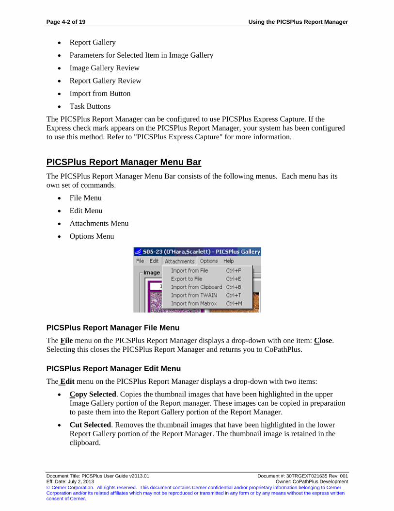
Page 4-2 of 19 Using the PICSPlus Report Manager
Document Title: PICSPlus User Guide v2013.01 Document #: 30TRGEXT021635 Rev: 001 Eff. Date: July 2, 2013 Owner: CoPathPlus Development
Cerner Corporation. All rights reserved. This document contains Cerner confidential and/or proprietary information belonging to Cerner Corporation and/or its related affiliates which may not be reproduced or transmitted in any form or by any means without the express written consent of Cerner.
Report Gallery
Parameters for Selected Item in Image Gallery
Image Gallery Review
Report Gallery Review
Import from Button
Task Buttons
The PICSPlus Report Manager can be configured to use PICSPlus Express Capture. If the
Express check mark appears on the PICSPlus Report Manager, your system has been configured
to use this method. Refer to "PICSPlus Express Capture" for more information.
PICSPlus Report Manager Menu Bar
The PICSPlus Report Manager Menu Bar consists of the following menus. Each menu has its
own set of commands.
File Menu
Edit Menu
Attachments Menu
Options Menu
PICSPlus Report Manager File Menu
The File menu on the PICSPlus Report Manager displays a drop-down with one item: Close.
Selecting this closes the PICSPlus Report Manager and returns you to CoPathPlus.
PICSPlus Report Manager Edit Menu
The Edit menu on the PICSPlus Report Manager displays a drop-down with two items:
Copy Selected. Copies the thumbnail images that have been highlighted in the upper
Image Gallery portion of the Report manager. These images can be copied in preparation
to paste them into the Report Gallery portion of the Report Manager.
Cut Selected. Removes the thumbnail images that have been highlighted in the lower
Report Gallery portion of the Report Manager. The thumbnail image is retained in the
clipboard.

Using the PICSPlus Report Manager Page 4-3 of 19
Document Title: PICSPlus User Guide v2013.01 Document #: 30TRGEXT021635 Rev: 001 Eff. Date: July 2, 2013 Owner: CoPathPlus Development
Cerner Corporation. All rights reserved. This document contains Cerner confidential and/or proprietary information belonging to Cerner Corporation and/or its related affiliates which may not be reproduced or transmitted in any form or by any means without the express written consent of Cerner.
Paste. After an image has been copied, the Paste option may be used to place the image
in the Report Gallery portion of the Report Manager. You can paste the image before a
current image in the Report gallery by clicking on the image and selecting the Paste
option. To paste an image at the end of the current selections, click in the empty portion
of the Report Gallery and select the Paste option.
Delete Selected. Deletes the images that have been selected. To select a single image,
move the mouse cursor over the image and depress the left mouse button. To select
several, but not all, images hold the CTRL key on the keyboard down and depress the left
mouse button on top of each image that you want to select. As you select the image the
border of the image will become colored as opposed to gray (the unselected color).
Select All. Selects all the images in the gallery.
PICSPlus Report Manager Attachments Menu
The Attachments menu on the PICSPlus Report Manager displays a drop-down with the
following items, which are determined on a per workstation basis appropriate to the acquisition
devices assigned to the workstation:
Import from File
Export to File
Import from Clipboard
Import from TWAIN
Import from Matrox
Note: The Import from Matrox option is only available to sites using the MIL-Lite version 7.5 drivers.
Import from File
When selecting the import option, the following window will appear. This is the Import
Attachment Window. You should select the image format (file type) of the image to be
imported. Highlight the type and select it. All of the images with that type format contained
within that directory will appear in the display window.
Tip: Import from File can also be invoked from the Gallery Manager with the keystrokes of Control + F.
Highlight the image of choice. To select multiple images, use Shift-Click to select a sequential
list of images. Use CTRL-Click to select multiple images not necessarily sequenced together.
Press the Open button to import the images. This window will close, and then the thumbnail of
the image will appear in the Image Gallery. Depending on default configurations, imported
images may or may not automatically be indicated to display on patient reports.
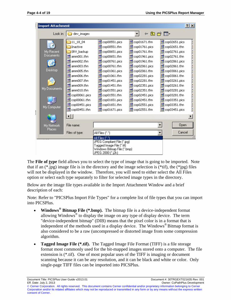
Page 4-4 of 19 Using the PICSPlus Report Manager
Document Title: PICSPlus User Guide v2013.01 Document #: 30TRGEXT021635 Rev: 001 Eff. Date: July 2, 2013 Owner: CoPathPlus Development
Cerner Corporation. All rights reserved. This document contains Cerner confidential and/or proprietary information belonging to Cerner Corporation and/or its related affiliates which may not be reproduced or transmitted in any form or by any means without the express written consent of Cerner.
The File of type field allows you to select the type of image that is going to be imported. Note
that if an (*.jpg) image file is in the directory and the image selection is (*tif), the (*jpg) files
will not be displayed in the window. Therefore, you will need to either select the All Files
option or select each type separately to filter for selected image types in the directory.
Below are the image file types available in the Import Attachment Window and a brief
description of each:
Note: Refer to "PICSPlus Import File Types" for a complete list of file types that you can import
into PICSPlus.
Windows® Bitmap File (*.bmp). The bitmap file is a device-independent format
allowing Windows®
to display the image on any type of display device. The term
"device-independent bitmap" (DIB) means that the pixel color is in a format that is
independent of the methods used in a display device. The Windows®
Bitmap format is
also considered to be a raw (uncompressed or distorted image from some compression
algorithm.
Tagged Image File (*.tif). The Tagged Image File Format (TIFF) is a file storage
format most commonly used for the bit-mapped images stored onto a computer. The file
extension is (*.tif). One of most popular uses of the TIFF is imaging or document
scanning because it can be any resolution, and it can be black and white or color. Only
single-page TIFF files can be imported into PICSPlus.

Using the PICSPlus Report Manager Page 4-5 of 19
Document Title: PICSPlus User Guide v2013.01 Document #: 30TRGEXT021635 Rev: 001 Eff. Date: July 2, 2013 Owner: CoPathPlus Development
Cerner Corporation. All rights reserved. This document contains Cerner confidential and/or proprietary information belonging to Cerner Corporation and/or its related affiliates which may not be reproduced or transmitted in any form or by any means without the express written consent of Cerner.
JPEG Compliant File (*.jpg). This format takes advantage of the human vision to
interpolate information that is not present. It compresses images using a discrete cosine
transform algorithm. It eliminates redundancy of pixels that meet specific frequency
criteria. JPEG stands for Joint Picture Expert Group. This was the name adopted by the
original imaging experts. This group created the compression algorithms standards.
JPEG 2000 (*.j2k). This format was developed to provide low bit rate operation with
rate-distortion and subjective image quality performance superior to existing standards,
without sacrificing performance at other points in the rate-distortion spectrum. This is
the format PICSPlus uses to store images.
PDF. Refer to "Import from PDF" for more information.
Note: When creating diagrams or other image files that will be embedded into reports, it is advised that the images
are created using a graphic editing tool that has 24-bit color. The image pixel resolution should be created at 640 x
480 at 96 dpi. Larger dpi’s will appear smaller on the report than the designated area and smaller dpi’s will appear
pixelated.
PICSPlus Import File Types
Thirty-four file formats are supported in PICSPlus for importing. All of these images are
converted to JPEG 2000 format once imported. The list of PICSPlus eligible file formats now
includes the following formats:
Amiga (*.iff) Portable Pixelmap (*ppm)
Brooktrout Fax (*.brk, *.301) SciTex Continuous Tone (*.sct, *.ct)
CALS Raster (*.cal, *.cals) SGI Image File (*.rgb, *.bw, *.rgba, *.sgi)
CompuServe Graphics Interchange (*.gif) Sun Raster Image (*.ras)
Deluxe Paint (*.lbm) Tagged Image File Format (*.tif, *.tiff)
Dr. Halo (*.cut) True Vision Targa (*.tga)
Encapsulated Post Script (*.eps, *.ps – monochrome
with preview only)
Windows Clipboard (*.clp)
GEM Paint (*.img) Windows Enhanced Meta File (*.emf)
JPEG (*.jpg, *.jif, *.jpeg) Window Metafile (*wmf – save bimpap data only)
JPEG 2000 (*.jp2, *.j2c, *.j2k, *.jpc, *.jpx) WindowsOrCompuServeRLE (*.rle)
Macintosh PICT (*.pct) Windows or OS2 Bitmap (*.bmp)
MacPaint (*.mac) Windows or OS2 DIB (.dib)
NCR G4 (*ncr) Wireless Bitmap (*wbmp)
Photoshop (*.psd) Xwindows Bitmap (*.xbm, *.bm)
Portable bitmap (*.pbm) XWIndows Dump (*.xwd, *.wd)
Protable Graymap (*.pgm) XWindowsPixmap (*.xpm)
Portable Network Graphics (*.png) ZSoft Paintbrush (*.pcx)
Files can only be exported in JPEG, BMP, TIFF and JPEG 2000 formats.
Import from PDF
PICSPlus offers the ability to convert and then import files that originate as electronic PDF files.
Import of PDF files requires that the file be rasterized or converted to an image file. When a
multi-page PDF is rasterized, each page will be converted, stored, and presented as a separate
image in the Image Gallery. Files stored as images files are not re-converted to PDFs if they are
exported.

Page 4-6 of 19 Using the PICSPlus Report Manager
Document Title: PICSPlus User Guide v2013.01 Document #: 30TRGEXT021635 Rev: 001 Eff. Date: July 2, 2013 Owner: CoPathPlus Development
Cerner Corporation. All rights reserved. This document contains Cerner confidential and/or proprietary information belonging to Cerner Corporation and/or its related affiliates which may not be reproduced or transmitted in any form or by any means without the express written consent of Cerner.
Set the preferred resolution value in the "Resolution for PDF conversion into the raster image
(pixels/Inch)" field before acquiring a PDF image. The resolution of the PDF is set according to
this value when the PDF is acquired. The resolution cannot be changed on an already acquired
file. If you need an imported file to be retained at a different resolution, delete the originally
acquired file. Change the value in the "Resolution for PDF conversion into the raster image
(pixels/Inch) field" setting and then re-acquire that PDF.
Increasing the resolution value will provide better conversion quality but will also increase file
size and conversion time. Resolution cannot improve quality of the original document.
Experiment to determine the optimal value for your documents and set the default value
accordingly.
To modify the default resolution, press on the up arrow or down arrow spin control. Resolution
levels will change in increments of 50 and range between 100 and 600.
When the rasterization technology is used for saving a consult report to a case, you may wish to
include this image in a fairly large size on your patient report. As with other images, define an
attachment type with appropriate dimensions and set it to be allowed to print on patient reports.
When defining an image size, remember that the image must fit within the header, footer, and
side margins defined for your patient report template(s). In addition, you must also allow room
for the image title to print beneath the report. In circumstances where the defined height and
width of your image size in the Attachment Type Dictionary is not proportional to the image
itself, the image will resize itself to maintain proportionality. Do not define a image that is too
large to fit within your patient report borders. For example, for a report template that uses 1.2
inch header, footer, right margin, and left margin, a rasterized image of a PDF that was formerly
11 x 8.5 might be sized to 9.5 x 7.35. Perform your own experiments with rasterized images
that are both "busy" and "fairly light" on content to determine what works best for your lab.
Note: The Resolution for PDF Conversion field affects quality of the image (formerly the PDF) that is retained
within CoPathPlus. The Print Quality field in the Attachment Type Dictionary affects print quality of a specific
attachment type when it is printed on a patient report generated by the site’s text editor. Consider both your specific
requirements in image retention and report display, and then balance these needs against the required conversion
time, storage, and printer resources when setting these two parameters. For example, you might opt to retain the
image at a fairly high resolution, but realize you can set a relatively low print quality and still have an acceptable
report display. For formatted patient reports sent via a MIME or PDF interface that do not already use an already
created PDF, interface configuration determine image resolution within the patient report.
Export to File
Any images assigned to a CoPathPlus specimen may also be exported.
To Export an Image:
1) Access the Image Gallery.
2) Select the image(s) you want to export. If you are selecting multiple images, hold down
the CTRL key when selecting images in a list and CTRL + Shift when selecting non-
sequential images.
3) Select Export to File from the File menu or press CTRL + E.
The Export Attachment window appears.

Using the PICSPlus Report Manager Page 4-7 of 19
Document Title: PICSPlus User Guide v2013.01 Document #: 30TRGEXT021635 Rev: 001 Eff. Date: July 2, 2013 Owner: CoPathPlus Development
Cerner Corporation. All rights reserved. This document contains Cerner confidential and/or proprietary information belonging to Cerner Corporation and/or its related affiliates which may not be reproduced or transmitted in any form or by any means without the express written consent of Cerner.
4) Navigate to the drive and folder where the images should be saved. Enter the file name
and select the format (file type) of the image(s) to be exported. If you are exporting
multiple files, enter a prefix that will be applied as the first part of the name of all images
selected. Click Save. The system will provide a warning regarding imaging naming,
relating that all images will receive the same prefix that will then be followed by a dash
and a sequence number should the user continue with the export. Click OK to continue
with the export.
After saving the images, the Export Attachments Window will close and return to the Image.
Import from TWAIN
You can acquire an image from a TWAIN device by clicking on the Import from TWAIN
option. This will launch the TWAIN compliant software acquisition application that
accompanied the TWAIN device. You should be familiar with the operation of the device. The
PICSPlus software will see the TWAIN information and open the image acquisition part of the
software. All software functionality will not be available during this activity within PICSPlus
since it only sees the information that allows the acquisition mode of the application.
Note: It is possible to have more than one TWAIN device attached to your workstation. If this is the case, assign
the desired TWAIN device prior to performing the TWAIN import. Refer to PICSPlus Gallery Manager Options
Menu: TWAIN, Select TWAIN Source for additional information.
It is recommended that before you execute the Import from TWAIN option that the object to be
acquired be placed on the scanner or within the camera’s view. Once the Import from TWAIN
option is executed, the TWAIN software will open and the familiar application window will
appear. It will begin the scan of the object on the scanner. If the device is a camera the live
image should appear in the viewfinder of the window.
After the image is acquired it will then be ready to edit by the TWAIN software with the limited
accessible software functionality. After you have edited the image it can then be sent to the
PICSPlus. There should an activity button (depending on the device) available to send the
acquired image to the PICSPlus.
When the application has finished acquiring the image, it will close and return you to the
PICSPlus View Manager where the image will be displayed. You can now perform all of the
functions normally available in the PICSPlus View Manager.

Page 4-8 of 19 Using the PICSPlus Report Manager
Document Title: PICSPlus User Guide v2013.01 Document #: 30TRGEXT021635 Rev: 001 Eff. Date: July 2, 2013 Owner: CoPathPlus Development
Cerner Corporation. All rights reserved. This document contains Cerner confidential and/or proprietary information belonging to Cerner Corporation and/or its related affiliates which may not be reproduced or transmitted in any form or by any means without the express written consent of Cerner.
Tip: Import from TWAIN can also be invoked from the Gallery Manager with the keystrokes of Control + T.
Refer to “Fast Scanning With Automatic Document Feeder (ADF) Support” in the “Using the
PICSPlus Gallery Manager” in this guide for information on importing from a scanner with
Automatic Document Feeder (ADF) support.
Import from Clipboard
You can directly images from a variety of image editors and viewers, including the web browser
using the Import from Clipboard option. This option will import an image that you have copied
to the Clipboard into PICSPlus. The Clipboard is the memory area (buffer) where data is stored
temporarily before being copied to another location. For example, if you copy a picture from a
web page and then use the Import from Clipboard option, you can paste the image into PICSPlus.
To import an image from the Clipboard, copy the image from the application where the image is
located. To copy an image from a web page using Internet Explorer, right-click the mouse over
the image and select Copy from the menu that appears. To copy images from other applications;
refer to the application’s user documentation. After you have copied the image, switch to the
PICSPlus Gallery Manager and select the Import from Clipboard option. The image will then
appear in the Gallery Manager.
Tip: Import from Clipboard can also be invoked from the Gallery Manager with the keystrokes of Control + B.
Import from Matrox
When using the PICSPlus Acquisition Manager associated Matrox, the Matrox Acquisition
manager may be invoked via the following methods:
When a workstation has defined Matrox acquisition as the default acquisition method,
click on the Import from Matrox button. (Refer to "Default Import Action" for more
information.)
The following methods to invoke Matrox Import can be used whether the Matrox is the
default acquisition method or it the workstation is only used for occasional Matrox
acquisitions, thus the default acquisition method is defined to be a different import type:
Click on the Attachments menu and then select the Import from Matrox Item
Simultaneously press the CTRL and the M key.
The Matrox Acquisition Manager will be displayed after any of these methods are used. The
following is an example of the Matrox Acquisition Manager

Using the PICSPlus Report Manager Page 4-9 of 19
Document Title: PICSPlus User Guide v2013.01 Document #: 30TRGEXT021635 Rev: 001 Eff. Date: July 2, 2013 Owner: CoPathPlus Development
Cerner Corporation. All rights reserved. This document contains Cerner confidential and/or proprietary information belonging to Cerner Corporation and/or its related affiliates which may not be reproduced or transmitted in any form or by any means without the express written consent of Cerner.
This window is used to acquire (capture) the image. Position the display on your Matrox devices
to the appropriate position and acquire the image. The image is captured either by clicking on
the Acquire button, pressing Alt + Q or simply pressing the Enter key since the Acquire button is
the default key for the screen.
Following image acquisition, the screen display will either return to the Image Gallery or it will
open the PICSPlus View Manager, where annotations may be made.
PICSPlus Report Manager Options Menu
The Options menu on the PICSPlus Report Manager displays a drop-down with two items:
Default Import Action
Default Import Template
TWAIN
Image Viewer
The Image Viewer menu display contains the following item:
Load with maximized view
This option lets you select to open images in the PICSPlus View Manager by default in
Maximize View or in Normal View. If you select this option and place a check mark next to it,
as displayed in the illustration below, when you open images from the Gallery Manager, the
images will open in Maximize View. If there is no check mark, the images will open in Normal
View.
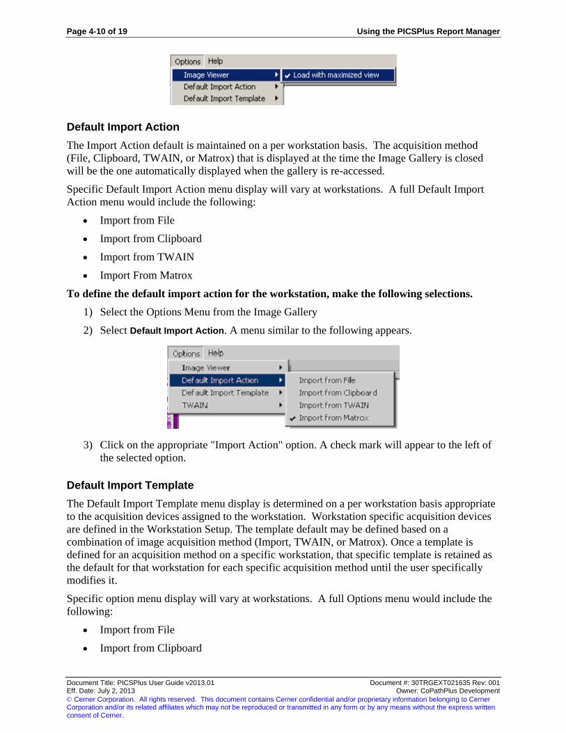
Page 4-10 of 19 Using the PICSPlus Report Manager
Document Title: PICSPlus User Guide v2013.01 Document #: 30TRGEXT021635 Rev: 001 Eff. Date: July 2, 2013 Owner: CoPathPlus Development
Cerner Corporation. All rights reserved. This document contains Cerner confidential and/or proprietary information belonging to Cerner Corporation and/or its related affiliates which may not be reproduced or transmitted in any form or by any means without the express written consent of Cerner.
Default Import Action
The Import Action default is maintained on a per workstation basis. The acquisition method
(File, Clipboard, TWAIN, or Matrox) that is displayed at the time the Image Gallery is closed
will be the one automatically displayed when the gallery is re-accessed.
Specific Default Import Action menu display will vary at workstations. A full Default Import
Action menu would include the following:
Import from File
Import from Clipboard
Import from TWAIN
Import From Matrox
To define the default import action for the workstation, make the following selections.
1) Select the Options Menu from the Image Gallery
2) Select Default Import Action. A menu similar to the following appears.
3) Click on the appropriate "Import Action" option. A check mark will appear to the left of
the selected option.
Default Import Template
The Default Import Template menu display is determined on a per workstation basis appropriate
to the acquisition devices assigned to the workstation. Workstation specific acquisition devices
are defined in the Workstation Setup. The template default may be defined based on a
combination of image acquisition method (Import, TWAIN, or Matrox). Once a template is
defined for an acquisition method on a specific workstation, that specific template is retained as
the default for that workstation for each specific acquisition method until the user specifically
modifies it.
Specific option menu display will vary at workstations. A full Options menu would include the
following:
Import from File
Import from Clipboard
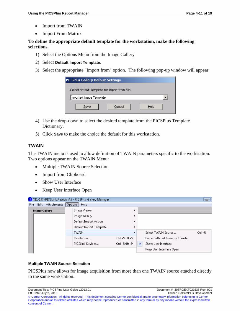
Using the PICSPlus Report Manager Page 4-11 of 19
Document Title: PICSPlus User Guide v2013.01 Document #: 30TRGEXT021635 Rev: 001 Eff. Date: July 2, 2013 Owner: CoPathPlus Development
Cerner Corporation. All rights reserved. This document contains Cerner confidential and/or proprietary information belonging to Cerner Corporation and/or its related affiliates which may not be reproduced or transmitted in any form or by any means without the express written consent of Cerner.
Import from TWAIN
Import From Matrox
To define the appropriate default template for the workstation, make the following
selections.
1) Select the Options Menu from the Image Gallery
2) Select Default Import Template.
3) Select the appropriate "Import from" option. The following pop-up window will appear.
4) Use the drop-down to select the desired template from the PICSPlus Template
Dictionary.
5) Click Save to make the choice the default for this workstation.
TWAIN
The TWAIN menu is used to allow definition of TWAIN parameters specific to the workstation.
Two options appear on the TWAIN Menu:
Multiple TWAIN Source Selection
Import from Clipboard
Show User Interface
Keep User Interface Open
Multiple TWAIN Source Selection
PICSPlus now allows for image acquisition from more than one TWAIN source attached directly
to the same workstation.
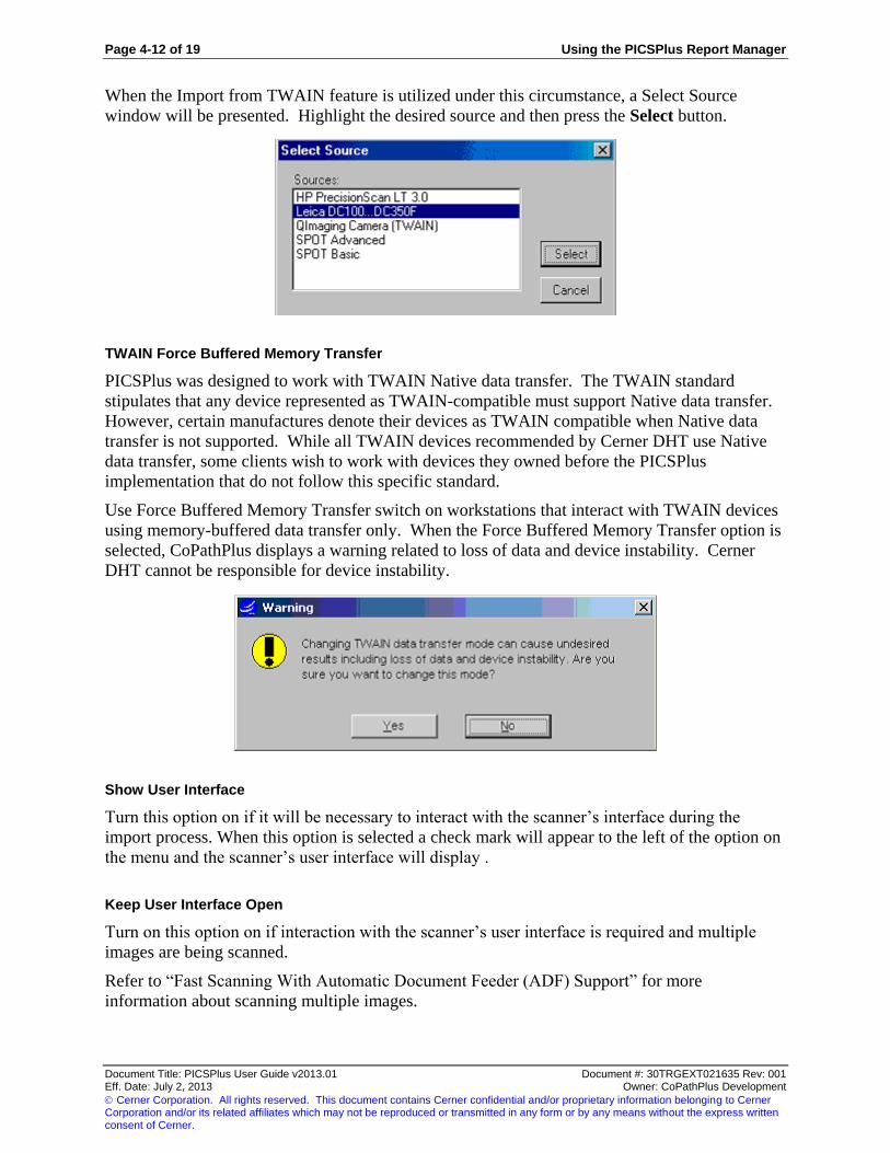
Page 4-12 of 19 Using the PICSPlus Report Manager
Document Title: PICSPlus User Guide v2013.01 Document #: 30TRGEXT021635 Rev: 001 Eff. Date: July 2, 2013 Owner: CoPathPlus Development
Cerner Corporation. All rights reserved. This document contains Cerner confidential and/or proprietary information belonging to Cerner Corporation and/or its related affiliates which may not be reproduced or transmitted in any form or by any means without the express written consent of Cerner.
When the Import from TWAIN feature is utilized under this circumstance, a Select Source
window will be presented. Highlight the desired source and then press the Select button.
TWAIN Force Buffered Memory Transfer
PICSPlus was designed to work with TWAIN Native data transfer. The TWAIN standard
stipulates that any device represented as TWAIN-compatible must support Native data transfer.
However, certain manufactures denote their devices as TWAIN compatible when Native data
transfer is not supported. While all TWAIN devices recommended by Cerner DHT use Native
data transfer, some clients wish to work with devices they owned before the PICSPlus
implementation that do not follow this specific standard.
Use Force Buffered Memory Transfer switch on workstations that interact with TWAIN devices
using memory-buffered data transfer only. When the Force Buffered Memory Transfer option is
selected, CoPathPlus displays a warning related to loss of data and device instability. Cerner
DHT cannot be responsible for device instability.
Show User Interface
Turn this option on if it will be necessary to interact with the scanner’s interface during the
import process. When this option is selected a check mark will appear to the left of the option on
the menu and the scanner’s user interface will display .
Keep User Interface Open
Turn on this option on if interaction with the scanner’s user interface is required and multiple
images are being scanned.
Refer to “Fast Scanning With Automatic Document Feeder (ADF) Support” for more
information about scanning multiple images.

Using the PICSPlus Report Manager Page 4-13 of 19
Document Title: PICSPlus User Guide v2013.01 Document #: 30TRGEXT021635 Rev: 001 Eff. Date: July 2, 2013 Owner: CoPathPlus Development
Cerner Corporation. All rights reserved. This document contains Cerner confidential and/or proprietary information belonging to Cerner Corporation and/or its related affiliates which may not be reproduced or transmitted in any form or by any means without the express written consent of Cerner.
Image Gallery
The Image Gallery is an object on the PICSPlus Gallery Manager and PICSPlus Report
Manager that provides a place to review the thumbnails of the images that have been acquired
within the currently active patient record.
The image name for each thumbnail image is displayed in the upper portion of the image frame.
The image type abbreviation is displayed in the lower portion of the image frame for each
thumbnail. These abbreviations are defined in the Attachment Type Dictionary. Refer to
"Attachment Type Dictionary” for more information.
Selecting an Image in the Image and Report Galleries
To select an image from the Image Gallery or the Report Gallery, place the cursor over the image
and click the left mouse button once. This will highlight the border of the image. At the same
time, the list box within the Parameters for Selected Item in Image Gallery will appear. This will
list the parameters of the specifically selected image. For more information, refer to "Parameters
for Selected Item in Image Gallery." To deselect an image, click on a different image to be
selected or click on an empty space in the Image Gallery.
The following illustration displays examples of thumbnails in selected and unselected state:
Note: You can also select an image in the Image Gallery and press the CTRL + L shortcut to open the PICSPlus
View Manager.

Page 4-14 of 19 Using the PICSPlus Report Manager
Document Title: PICSPlus User Guide v2013.01 Document #: 30TRGEXT021635 Rev: 001 Eff. Date: July 2, 2013 Owner: CoPathPlus Development
Cerner Corporation. All rights reserved. This document contains Cerner confidential and/or proprietary information belonging to Cerner Corporation and/or its related affiliates which may not be reproduced or transmitted in any form or by any means without the express written consent of Cerner.
It is also possible to select multiple images by pressing the Shift or CTRL key in conjunction with
clicking the mouse. This is useful for exporting multiple images. Refer to "Image and Report
Gallery Keyboard and Mouse Shortcuts” for more information.
Note: If multiple images are selected, the Parameter data will not display in the Parameter List Box.
Image and Report Gallery Keyboard and Mouse Shortcuts
The following table displays the Keyboard and Mouse Shortcuts for the Image Gallery. These
shortcuts also apply to the Report Gallery.
Action Mouse Keyboard Mouse and Keyboard
Select single thumbnail Left-click Ctrl + space bar (If
thumbnail has focus
indicator)
Ctrl + Left-click
Unselect single thumbnail Left-click on
empty space
(unselect all
selected
thumbnails)
Ctrl + space bar (If
thumbnail has focus
indicator)
Shift + Left-click
Move focus indicator
without selecting thumbnail
N/A Ctrl + Arrow (Left, Right,
Up and Down) or Home
(End) to move to the first
thumbnail or last thumbnail.
N/A
Select all thumbnails Right-click on any
place within the
Gallery and Left-
click on Select All
Menu Item.
Ctrl + A Select first
thumbnail and Shift
+ Left-click on last
thumbnail
Unselect all thumbnails Left-click on
empty space
Press Home(or End) and
after that Ctrl + space bar
Left-click on any
thumbnail and after
that Ctrl + space bar
Delete selected thumbnail
(thumbnails)
Right-click on any
place within the
Gallery and Left-
click on Delete
Selected Menu
Item.
Del N/A
Load PICSPlus Image
Viewer (Image Gallery
Only)
Double-click on
thumbnail
Ctrl + L N/A
Report Gallery
The Report Gallery is an object on the PICSPlus Report Manager that displays all of the images
selected to be on the report. The images have either been placed there by default (created in the
Attachment Type Dictionary), or they have been selected to be there by selecting image(s) in the
Image Gallery and transferred to the Report Gallery. To transfer the images from the Image
Gallery to the Report Gallery, first select the image to be placed on the report. Click on that
image in the Image Gallery and while holding down the left mouse button, drag the cursor to the
Report Gallery and release the button. This will transfer the thumbnail of the image to the
Report Gallery.

Using the PICSPlus Report Manager Page 4-15 of 19
Document Title: PICSPlus User Guide v2013.01 Document #: 30TRGEXT021635 Rev: 001 Eff. Date: July 2, 2013 Owner: CoPathPlus Development
Cerner Corporation. All rights reserved. This document contains Cerner confidential and/or proprietary information belonging to Cerner Corporation and/or its related affiliates which may not be reproduced or transmitted in any form or by any means without the express written consent of Cerner.
To remove image(s) from the Report Gallery, select the image by clicking the left mouse button
on the image. The image border will be highlighted. If more than one image is to be removed
hold down the keyboard Ctrl Key and select each image that is to be removed. Now each of the
images selected to be removed from the gallery will be highlighted. You can either click the
right mouse button to open a pop-up edit menu or select the edit menu from the menu bar. In
either case select the Delete Selected item and the images will be removed from the Report
Gallery. This does not delete images from the Image Gallery. The images removed from the
Report Gallery are still in the Image Gallery.
Refer to "Selecting an Image in the Image and Report Galleries" and "Image and Report Gallery
Keyboard and Mouse Shortcuts" for more information.
Parameters for Selected Item in Image Gallery
This component of the PICSPlus Gallery Manager and Report Manager is a list box of the
parameters assigned to the selected image within the Image Gallery or Report Gallery. See the
figure below.
To select an image, place the cursor over the image and click the left mouse button once. This
will highlight the border of the image. At the same time, the list box within the Parameters for
Selected Item in Image Gallery will appear. This will list the parameters of the selected image.

Page 4-16 of 19 Using the PICSPlus Report Manager
Document Title: PICSPlus User Guide v2013.01 Document #: 30TRGEXT021635 Rev: 001 Eff. Date: July 2, 2013 Owner: CoPathPlus Development
Cerner Corporation. All rights reserved. This document contains Cerner confidential and/or proprietary information belonging to Cerner Corporation and/or its related affiliates which may not be reproduced or transmitted in any form or by any means without the express written consent of Cerner.
There are two columns in this list: Name and Value. These values are either assigned by the user
or by the system, depending on the type of parameter. The names of the parameters are set-up in
the PICSPlus Template Dictionary. These parameters are attributes assigned to images. Some
information is automatically captured; other information will be manually entered. Parameters
may be defined as either mandatory or optional fields. If desired, parameters can be set-up under
the DICOM standard for image information. It is the user’s discretion as to which parameters
best suit the needs at the time the system is set-up. Some useful parameters include, but are not
limited to: Image Type, Image Title, Date of Capture, Person Acquiring Image, Type of Camera
Used, Image Format, Size of Image and Color Depth of Image.
For more information, refer to "PICSPlus Template Dictionary" in this guide.
Image Gallery Review
Image Gallery Review allows you to browse through all images in the Image Gallery from either
the Gallery Manager or the Report Manager using a Manual Display method or a Timer Display
method. Whichever method you choose, the images in the Image Gallery will display in the
order in which they appear in the gallery. When the last image in the image gallery is displayed,
the images will repeat in the same order.
If you select the Manual Display method, the image display will only change when you press the
spacebar. If you select the Timer Display method, the image display will transition using the
timer settings you select. Refer to "Adjusting the Review Display Options” for information on
selecting the display method and changing the display options.
To use the Image Gallery Review feature:
1) Click the Image Gallery Review button on the Image Gallery or the Report Gallery.
The Review Window will appear.
2) Press the space bar to begin the image gallery review. The review method will default to
the last selected setting for the display, either Timer or Manual. Refer to "Adjusting the
Review Display Options” for more information.
If you are using the Manual display option and have selected to use the Magnifier, you
can click the mouse to magnify a section of the image. You can set the options for the
magnifier using the Display Setup menu.
During the Image Gallery Review, you can press the Pause button on the keyboard to
pause the review and then press the spacebar to resume the review.
3) When you are finished with the review, click the Esc key.
Adjusting the Review Display Options
To adjust the review display settings:
1) Follow the steps outlined in "Image Gallery Review” or "Report Gallery Review" to open
the Review window.
2) Right-click the mouse to open the menu displayed below.

Using the PICSPlus Report Manager Page 4-17 of 19
Document Title: PICSPlus User Guide v2013.01 Document #: 30TRGEXT021635 Rev: 001 Eff. Date: July 2, 2013 Owner: CoPathPlus Development
Cerner Corporation. All rights reserved. This document contains Cerner confidential and/or proprietary information belonging to Cerner Corporation and/or its related affiliates which may not be reproduced or transmitted in any form or by any means without the express written consent of Cerner.
3) You can select the following display options from the menu available on the Review
Window:
Use Magnifier. This option only appears if you are using the Manual Display method
(pressing the spacebar to transition through the images). Select this option if you want to
be able to easily magnify a section of the image by clicking the mouse on it. You can
hold the mouse button down and scroll around the image to view any part in the
magnified view. You can set the options for the magnifier using the Display Setup menu.
See below for more information.
Use Timer. Select this option to automate the transition of images using the timer. You
can set the length of the timer using the using the Display Setup menu. See below for
more information.
Show Marks. Select this option if you want any marks that have not been burned on the
image to appear when you use the Image Gallery Review feature. Marks are objects that
can be placed on a PICSPlus image to bring attention to or focus on a specific area of the
image. You can mark PICSPlus images when using the PICSPlus View Manager.
Display Setup. Select this option to make changes to the Timer or Magnifier. The
following illustration is an example of the Display Setup window.
4) You can configure the following settings on the Display Setup window:
Timer. Enter the number of seconds you want the image to display before advancing to
the next image. You can type a number or use the spin controls.
Magnifier. The following are options for configuring the magnifier:

Page 4-18 of 19 Using the PICSPlus Report Manager
Document Title: PICSPlus User Guide v2013.01 Document #: 30TRGEXT021635 Rev: 001 Eff. Date: July 2, 2013 Owner: CoPathPlus Development
Cerner Corporation. All rights reserved. This document contains Cerner confidential and/or proprietary information belonging to Cerner Corporation and/or its related affiliates which may not be reproduced or transmitted in any form or by any means without the express written consent of Cerner.
Size (Pixels). Enter the Width and Height in pixels of the magnifier. You can type
a number or use the spin controls.
Shape. Select to view the magnifier in an eclipse shape or a rectangle shape.
Magnification. Enter the magnification level for the magnifier. You can type a
number or use the spin controls. The lowest number is 1 and the highest number
(the highest level of magnification) is 99.
The selections you make for the Review display options are saved as the default for the
workstation.
Report Gallery Review
Report Gallery Review allows you to browse through all images in the Report Gallery from the
Report Manager using a Manual Display method or a Timer Display method. Whichever method
you choose, the images in the Report Gallery will display in the order in which they appear in the
gallery. When the last image in the Report Gallery is displayed, the images will repeat in the
same order.
If you select the Manual Display method, the image display will only change when you press the
space bar. If you select the Timer Display method, the image display will transition using the
timer settings you select. Refer to "Adjusting the Review Display Options” for information on
selecting the display method and changing the display options.
To use the Report Gallery Review feature:
1) Click the Report Gallery Review button on the Report Gallery.
The Review Window will appear.
2) Press the space bar to begin the image gallery review. The review method will default to
the last selected setting for the display, either Timer or Manual. Refer to "Adjusting the
Review Display Options” for more information.
If you are using the Manual display option and have selected to use the Magnifier, you
can click the mouse to magnify a section of the image. You can set the options for the
magnifier using the Display Setup menu.
During the Report Gallery Review, you can press the Pause button on the keyboard to
pause the review and then press the spacebar to resume the review.
3) When you are finished with the review, click the Esc key.
Import From Button
The Import From button on the Image Gallery and the Report Gallery provides a quick alternative
for the image acquisition method of choice. The specific action of this button may be "Import
from File", "Import from Clipboard", "Import from TWAIN" or "Import from Matrox". It is set
up on a per workstation basis via selection of the Default Import Action on the Options menu.

Using the PICSPlus Report Manager Page 4-19 of 19
Document Title: PICSPlus User Guide v2013.01 Document #: 30TRGEXT021635 Rev: 001 Eff. Date: July 2, 2013 Owner: CoPathPlus Development
Cerner Corporation. All rights reserved. This document contains Cerner confidential and/or proprietary information belonging to Cerner Corporation and/or its related affiliates which may not be reproduced or transmitted in any form or by any means without the express written consent of Cerner.
Task Buttons
The following button is available on the PICSPlus Gallery Manager and Report Manager:
Close. Closes the PICSPlus Gallery or Report Manager and returns you to CoPathPlus.

Using the PICSPlus View Manager Page 5-1 of 41
Document Title: PICSPlus User Guide v2013.01 Document #: 30TRGEXT021635 Rev: 001 Eff. Date: July 2, 2013 Owner: CoPathPlus Development
Cerner Corporation. All rights reserved. This document contains Cerner confidential and/or proprietary information belonging to Cerner Corporation and/or its related affiliates which may not be reproduced or transmitted in any form or by any means without the express written consent of Cerner.
Chapter 5: Using the PICSPlus View Manager
To view an image from the PICSPlus Gallery Manager or Report Manager, double-click on the
thumbnail image of interest. This will open that image in the PICSPlus View Manager.
PICSPlus calculates the Zoom ratio of the displayed image to best fit the Image box thus opening
a “full size” image each time.
Note: You can also select an image on the Gallery Manager and press the CTRL + L shortcut to open the PICSPlus
View Manager.
PICSPlus can be launched automatically after acquiring an image when the View Image after
import check box is activated. This is the case for imported images from a file or the clipboard,
TWAIN acquisitions, and Matrox acquisitions.
The image will be displayed on the left side of the window.
The following features are available from the PICSPlus View Manager:
Maximize View
Copy to Clipboard

Page 5-2 of 41 Using the PICSPlus View Manager
Document Title: PICSPlus User Guide v2013.01 Document #: 30TRGEXT021635 Rev: 001 Eff. Date: July 2, 2013 Owner: CoPathPlus Development
Cerner Corporation. All rights reserved. This document contains Cerner confidential and/or proprietary information belonging to Cerner Corporation and/or its related affiliates which may not be reproduced or transmitted in any form or by any means without the express written consent of Cerner.
Save
Zoom Controls
Close
View Manager Toolbox
Maximize View
Clicking the Maximize View button gives you the largest possible space for displaying your
image. The menus and toolbars are hidden, except for the Normal View button. To restore the
menus and toolbars and return the screen to normal, click the Normal View button or the press the
ESC key
To magnify a portion of the view:
1) While the view is maximized, right-click on the image to open the Maximize View menu,
displayed below.
2) If it is not already checked, click Use Magnifier so a check appears to the left of the
menu item. This will allow you to easily magnify a section of the image by clicking the
mouse on it. You can hold the mouse button down and scroll around the image to view
any part in the magnified view.
Example of Non-Magnified view:
Example of Magnified view:

Using the PICSPlus View Manager Page 5-3 of 41
Document Title: PICSPlus User Guide v2013.01 Document #: 30TRGEXT021635 Rev: 001 Eff. Date: July 2, 2013 Owner: CoPathPlus Development
Cerner Corporation. All rights reserved. This document contains Cerner confidential and/or proprietary information belonging to Cerner Corporation and/or its related affiliates which may not be reproduced or transmitted in any form or by any means without the express written consent of Cerner.
To Configure the Magnifier:
1) Right-click on the image to open the Maximize View menu.
2) Select Display Setup from the menu. The following illustration is an example of the
Display Setup window.
2) You can configure the following settings on the Display Setup window:
o Size (Pixels). Enter the Width and Height in pixels of the magnifier. You can type a
number or use the spin controls.
o Shape. Select to view the magnifier in an eclipse shape or a rectangle shape.
o Magnification. Enter the magnification level for the magnifier. You can type a
number or use the spin controls. The lowest number is 1 and the highest number (the
highest level of magnification) is 99.
The selections you make on the Maximize View menu are saved as the default for the
workstation.

Page 5-4 of 41 Using the PICSPlus View Manager
Document Title: PICSPlus User Guide v2013.01 Document #: 30TRGEXT021635 Rev: 001 Eff. Date: July 2, 2013 Owner: CoPathPlus Development
Cerner Corporation. All rights reserved. This document contains Cerner confidential and/or proprietary information belonging to Cerner Corporation and/or its related affiliates which may not be reproduced or transmitted in any form or by any means without the express written consent of Cerner.
Copy to Clipboard
The Copy to Clipboard feature allows you to copy the image that is displayed in the PICSPlus
View Manager into the Clipboard. It will copy the image with any marks (annotations). The
marks do not have to be burned into the image for them to be placed onto the Clipboard.
The Print feature allows you to print the image displayed in the PICSPlus View Manager. When
the new Print button in the PICSPlus Viewer is pressed, a Print pop-up window is invoked
allowing the user to select a network printer and the number of copies. The Properties pop-up
allows definition of paper orientation, layout, and tray selection. The Image Settings pop-up
allows the user to specify where the image is positioned on the page. By default, ImageGear
software (parameters defined in the Print popup window and child windows) is used to render
the image. A check box is provided if you opt to use the designated Printer’s print driver
parameters to render the image. Print drivers on all printers may not provide the same parameter
options.
To preserve the aspect ratio of the printed image adjust sliders to eliminate the gray area.
Save
To save any marks or burns you have made on the image, click the Save button. If the Save
button is grayed out, there is nothing on the image to save. If you click the Close button before
you have saved the image, you will be prompted to save your changes.
Zoom Controls
The Zoom Controls on the PICSPlus View Manager let you increase or decrease the size of the
image in the Viewer.
NOTE: Increasing the size of the image will eventually distort the image from its original and true presentation
features – it will become pixelated. As the image is decreased in size, again the image will become distorted from
its original or true presentation features. As the size decreases any marks that have been burned into the image will
eventually become distorted and not display on the decreased image, The mark will appear normal once again if the
image is returned to original size.
The following table describes the menu buttons and keyboard shortcuts for the zoom actions on
the View Manager.
Action Zoom Button Zoom Shortcut
Zoom In
Press Numeric Keypad +
Zoom Out
Press Numeric Keypad -
Fit to Window
Press Numeric Keypad *

Using the PICSPlus View Manager Page 5-5 of 41
Document Title: PICSPlus User Guide v2013.01 Document #: 30TRGEXT021635 Rev: 001 Eff. Date: July 2, 2013 Owner: CoPathPlus Development
Cerner Corporation. All rights reserved. This document contains Cerner confidential and/or proprietary information belonging to Cerner Corporation and/or its related affiliates which may not be reproduced or transmitted in any form or by any means without the express written consent of Cerner.
Normal 1:1
ratio
Press Numeric Keypad /
You can determine the zoom ratio by looking at the Zoom Level indicator located just above the
image on the left side. As the zoom ration increases, images will lose clarity.
Because the image is larger than the display area, there are scroll bars along the right vertical
border and the bottom horizontal border. This allows you to move the image around to see the
other areas unable to be displayed due to the size.
Close
Selecting this option closes the PICSPlus View Manager. Any marks that were placed on the
image will remain on the image when they have been saved. If the marks have not been saved,
the system will prompt the user whether or not to save the changes. and the system will prompt
whether these marks. The thumbnail will have an asterisk before the title in the upper portion of
the image frame to denote that a mark is on (but not burned into) the image.
View Manager Toolbox
The View Manager Toolbox appears on the left side of the View Manager screen. The toolbox
contains four tabs:
Marks Tab
Process Tab
Colors Tab
Info Tab

Page 5-6 of 41 Using the PICSPlus View Manager
Document Title: PICSPlus User Guide v2013.01 Document #: 30TRGEXT021635 Rev: 001 Eff. Date: July 2, 2013 Owner: CoPathPlus Development
Cerner Corporation. All rights reserved. This document contains Cerner confidential and/or proprietary information belonging to Cerner Corporation and/or its related affiliates which may not be reproduced or transmitted in any form or by any means without the express written consent of Cerner.
The Info Tab will always display. The following scenarios must be in place for the other tabs to
display:
Process An acquisition method (Image import, Matrox, or
TWAIN) has been enabled for the workstation.
The image is not on a signed out report.
Colors The image is a grayscale or color image.
An acquisition method (Image import, Matrox, or
TWAIN) has been enabled for the workstation.
The image is not on a signed out report.
Marks The image is a grayscale or color image.
The workstation has been enabled for annotations.
The image is not on a signed out report.
Marks Tab
The Marks tab is one of four tabs located on the right of the PICSPlus View Manager. The
Marks tab contains the Marks toolbar and six buttons, as shown below.
Note: You can click on the Marks toolbar and drag it off of the Marks tab to allow easier access to the tools. To
return the Marks toolbar to the standard display, click the X in the upper right corner of the toolbar.
Marks or annotations are objects that can be placed on a PICSPlus image to bring attention to or
focus on a specific area of the image. You can mark PICSPlus images when using the PICSPlus
View Manager.
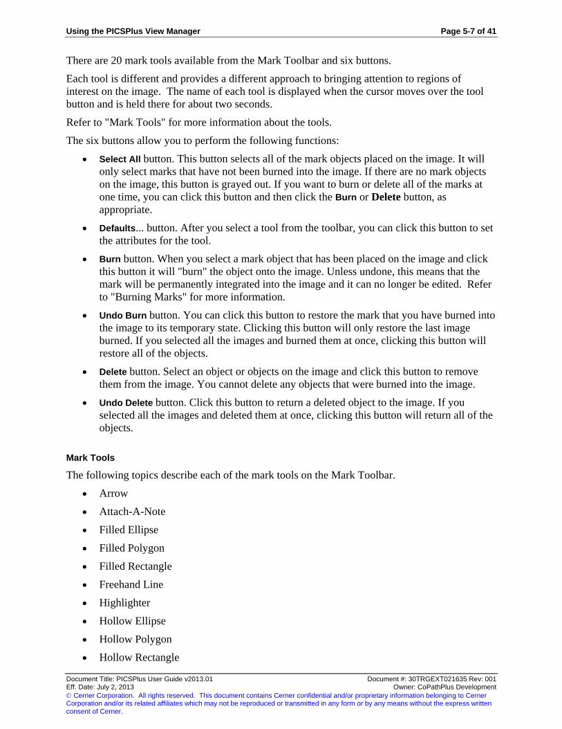
Using the PICSPlus View Manager Page 5-7 of 41
Document Title: PICSPlus User Guide v2013.01 Document #: 30TRGEXT021635 Rev: 001 Eff. Date: July 2, 2013 Owner: CoPathPlus Development
Cerner Corporation. All rights reserved. This document contains Cerner confidential and/or proprietary information belonging to Cerner Corporation and/or its related affiliates which may not be reproduced or transmitted in any form or by any means without the express written consent of Cerner.
There are 20 mark tools available from the Mark Toolbar and six buttons.
Each tool is different and provides a different approach to bringing attention to regions of
interest on the image. The name of each tool is displayed when the cursor moves over the tool
button and is held there for about two seconds.
Refer to "Mark Tools" for more information about the tools.
The six buttons allow you to perform the following functions:
Select All button. This button selects all of the mark objects placed on the image. It will
only select marks that have not been burned into the image. If there are no mark objects
on the image, this button is grayed out. If you want to burn or delete all of the marks at
one time, you can click this button and then click the Burn or Delete button, as
appropriate.
Defaults... button. After you select a tool from the toolbar, you can click this button to set
the attributes for the tool.
Burn button. When you select a mark object that has been placed on the image and click
this button it will "burn" the object onto the image. Unless undone, this means that the
mark will be permanently integrated into the image and it can no longer be edited. Refer
to "Burning Marks" for more information.
Undo Burn button. You can click this button to restore the mark that you have burned into
the image to its temporary state. Clicking this button will only restore the last image
burned. If you selected all the images and burned them at once, clicking this button will
restore all of the objects.
Delete button. Select an object or objects on the image and click this button to remove
them from the image. You cannot delete any objects that were burned into the image.
Undo Delete button. Click this button to return a deleted object to the image. If you
selected all the images and deleted them at once, clicking this button will return all of the
objects.
Mark Tools
The following topics describe each of the mark tools on the Mark Toolbar.
Arrow
Attach-A-Note
Filled Ellipse
Filled Polygon
Filled Rectangle
Freehand Line
Highlighter
Hollow Ellipse
Hollow Polygon
Hollow Rectangle
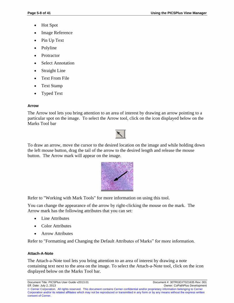
Page 5-8 of 41 Using the PICSPlus View Manager
Document Title: PICSPlus User Guide v2013.01 Document #: 30TRGEXT021635 Rev: 001 Eff. Date: July 2, 2013 Owner: CoPathPlus Development
Cerner Corporation. All rights reserved. This document contains Cerner confidential and/or proprietary information belonging to Cerner Corporation and/or its related affiliates which may not be reproduced or transmitted in any form or by any means without the express written consent of Cerner.
Hot Spot
Image Reference
Pin Up Text
Polyline
Protractor
Select Annotation
Straight Line
Text From File
Text Stamp
Typed Text
Arrow
The Arrow tool lets you bring attention to an area of interest by drawing an arrow pointing to a
particular spot on the image. To select the Arrow tool, click on the icon displayed below on the
Marks Tool bar
To draw an arrow, move the cursor to the desired location on the image and while holding down
the left mouse button, drag the tail of the arrow to the desired length and release the mouse
button. The Arrow mark will appear on the image.
Refer to "Working with Mark Tools" for more information on using this tool.
You can change the appearance of the arrow by right-clicking the mouse on the mark. The
Arrow mark has the following attributes that you can set:
Line Attributes
Color Attributes
Arrow Attributes
Refer to "Formatting and Changing the Default Attributes of Marks” for more information.
Attach-A-Note
The Attach-a-Note tool lets you bring attention to an area of interest by drawing a note
containing text next to the area on the image. To select the Attach-a-Note tool, click on the icon
displayed below on the Marks Tool bar.

Using the PICSPlus View Manager Page 5-9 of 41
Document Title: PICSPlus User Guide v2013.01 Document #: 30TRGEXT021635 Rev: 001 Eff. Date: July 2, 2013 Owner: CoPathPlus Development
Cerner Corporation. All rights reserved. This document contains Cerner confidential and/or proprietary information belonging to Cerner Corporation and/or its related affiliates which may not be reproduced or transmitted in any form or by any means without the express written consent of Cerner.
To draw the note, move the cursor to the desired location on the image and while holding down
the left mouse button, drag the pointer to the diagonally opposite corner of the drawing area (or
until all the default text is visible, if any) and release the mouse button. The Attach-a-Note mark
will appear on the image. The blinking text cursor will be inside the text area, ready for you to
enter text if desired.
Refer to "Working with Mark Tools" for more information on using this tool.
You can change the edit the appearance and text in the mark by right -clicking the mouse on the
mark. The Attach-a-Note mark has the following attributes that you can set:
Font Attributes
Color Attributes
Text Attributes
Refer to "Formatting and Changing the Default Attributes of Marks” for more information.
Filled Ellipse
The Filled Ellipse mark lets you bring attention to an area of interest by drawing a solid ellipse
on the image. To select the Filled Ellipse mark, click on the icon displayed below on the Marks
Tool bar.
To draw a filled ellipse, move the cursor to the desired location on the image and while holding
down the left mouse button, drag the pointer to the diagonally opposite corner of the drawing
area and release the mouse button. The Filled Ellipse mark will appear on the image.
Refer to "Working with Mark Tools" for more information on using this tool.
You can change the appearance of the filled ellipse by right -clicking the mouse on the mark.
The Filled Ellipse mark has the following attributes that you can set:
General Attributes
Color Attributes

Page 5-10 of 41 Using the PICSPlus View Manager
Document Title: PICSPlus User Guide v2013.01 Document #: 30TRGEXT021635 Rev: 001 Eff. Date: July 2, 2013 Owner: CoPathPlus Development
Cerner Corporation. All rights reserved. This document contains Cerner confidential and/or proprietary information belonging to Cerner Corporation and/or its related affiliates which may not be reproduced or transmitted in any form or by any means without the express written consent of Cerner.
Refer to "Formatting and Changing the Default Attributes of Marks” for more information.
Filled Polygon
The Filled Polygon mark lets you bring attention to an area of interest by drawing a solid
polygon on the image. To select the Filled Polygon mark, click on the icon displayed below on
the Marks Tool bar.
To draw a filled polygon, move the cursor to the desired location on the image and click the left
mouse button to anchor the point. Move the mouse to the next corner and click left again to
anchor the second point. Repeat this process for each corner until the polygon is drawn to the
desired shape. When you return to the first point to complete the shape, double-click the left
mouse button to finish drawing the polygon. The Filled Polygon mark will appear on the image.
Refer to "Working with Mark Tools" for more information on using this tool.
You can change the appearance of the filled polygon by right -clicking the mouse on the mark.
The Filled Polygon mark has the following attributes that you can set:
General Attributes
Color Attributes
Refer to "Formatting and Changing the Default Attributes of Marks” for more information.
Filled Rectangle
The Filled Rectangle mark lets you bring attention to an area of interest by drawing a solid
rectangle on the image. To select the Filled Rectangle mark, click on the icon displayed below
on the Marks Tool bar.
To draw a filled rectangle, move the cursor to the desired location on the image and while
holding down the left mouse button, drag the pointer to the diagonally opposite corner of the
drawing area and release the mouse button. The Filled Rectangle mark will appear on the image.
Refer to "Working with Mark Tools" for more information on using this tool.

Using the PICSPlus View Manager Page 5-11 of 41
Document Title: PICSPlus User Guide v2013.01 Document #: 30TRGEXT021635 Rev: 001 Eff. Date: July 2, 2013 Owner: CoPathPlus Development
Cerner Corporation. All rights reserved. This document contains Cerner confidential and/or proprietary information belonging to Cerner Corporation and/or its related affiliates which may not be reproduced or transmitted in any form or by any means without the express written consent of Cerner.
You can change the appearance of the filled rectangle by right -clicking the mouse on the mark.
The Filled Rectangle mark has the following attributes that you can set:
General Attributes
Color Attributes
Refer to "Formatting and Changing the Default Attributes of Marks” for more information.
Freehand Line
The Freehand Line mark lets you bring attention to an area of interest by drawing a freehand line
around a point on the image. To select the Freehand Line tool, click on the icon displayed below
on the Marks Tool bar.
To draw a freehand line, move the cursor to the desired location on the image and while holding
down the left mouse button, drag the pointer wherever you want and release the mouse button.
The Freehand Line mark will appear on the image.
Refer to "Working with Mark Tools" for more information on using this tool.
You can change the appearance of the freehand line by right -clicking the mouse on the mark.
The Freehand Line mark has the following attributes that you can set:
Line Attributes
Color Attributes
Refer to "Formatting and Changing the Default Attributes of Marks” for more information.
Highlighter
The Highlighter lets you bring attention to an area by drawing a Highlighter at that region of
interest. To select the Highlighter, click on the icon displayed below on the Marks Tool bar.
To draw the highlighter, place the center of Precision Pointer at one corner of the Highlighter to
be drawn and while holding down the left mouse button, drag the mouse to the diagonally
opposite corner of the area to be drawn and then release the key. The Highlighter mark will
appear on the image.

Page 5-12 of 41 Using the PICSPlus View Manager
Document Title: PICSPlus User Guide v2013.01 Document #: 30TRGEXT021635 Rev: 001 Eff. Date: July 2, 2013 Owner: CoPathPlus Development
Cerner Corporation. All rights reserved. This document contains Cerner confidential and/or proprietary information belonging to Cerner Corporation and/or its related affiliates which may not be reproduced or transmitted in any form or by any means without the express written consent of Cerner.
Refer to "Working with Mark Tools" for more information on using this tool.
You can change the color of the highlighter by right -clicking the mouse on the mark. The mark
will always display in a highlight mode; it will never be solid. The Highlighter mark has the
following attribute that you can set:
Color Attribute
Refer to "Formatting and Changing the Default Attributes of Marks” for more information.
Hollow Ellipse
The Hollow Ellipse mark lets you bring attention to an area of interest by drawing an ellipse
around the area on the image. To select the Hollow Ellipse mark, click on the icon displayed
below on the Marks Tool bar.
To draw a hollow ellipse, move the cursor to the desired location on the image and while holding
down the left mouse button, drag the pointer to the diagonally opposite corner of the drawing
area and release the mouse button. The Hollow Ellipse mark will appear on the image.
Refer to "Working with Mark Tools" for more information on using this tool.
You can change the appearance of the hollow ellipse by right -clicking the mouse on the mark.
The Hollow Ellipse mark has the following attributes that you can set:
Line Attributes
Color Attributes
Refer to "Formatting and Changing the Default Attributes of Marks” for more information.
Hollow Polygon
The Hollow Polygon mark lets you bring attention to an area of interest by drawing a hollow
polygon around the area on the image. To select the Hollow Polygon mark, click on the icon
displayed below on the Marks Tool bar.
To draw a hollow polygon, move the cursor to the desired location on the image and click the
left mouse button to anchor the point. Move the mouse to the next corner and click left again to
anchor the second point. Repeat this process for each corner until the polygon is drawn to the
desired shape. When you return to the first point to complete the shape, double-click the left
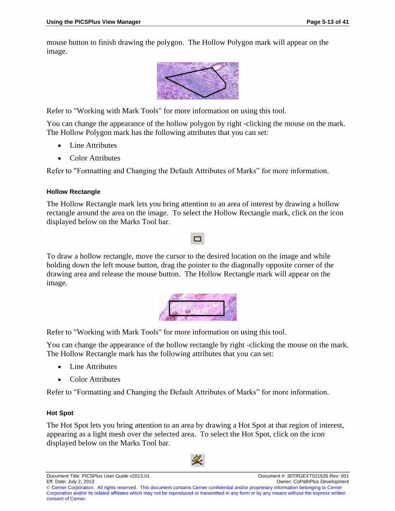
Using the PICSPlus View Manager Page 5-13 of 41
Document Title: PICSPlus User Guide v2013.01 Document #: 30TRGEXT021635 Rev: 001 Eff. Date: July 2, 2013 Owner: CoPathPlus Development
Cerner Corporation. All rights reserved. This document contains Cerner confidential and/or proprietary information belonging to Cerner Corporation and/or its related affiliates which may not be reproduced or transmitted in any form or by any means without the express written consent of Cerner.
mouse button to finish drawing the polygon. The Hollow Polygon mark will appear on the
image.
Refer to "Working with Mark Tools" for more information on using this tool.
You can change the appearance of the hollow polygon by right -clicking the mouse on the mark.
The Hollow Polygon mark has the following attributes that you can set:
Line Attributes
Color Attributes
Refer to "Formatting and Changing the Default Attributes of Marks” for more information.
Hollow Rectangle
The Hollow Rectangle mark lets you bring attention to an area of interest by drawing a hollow
rectangle around the area on the image. To select the Hollow Rectangle mark, click on the icon
displayed below on the Marks Tool bar.
To draw a hollow rectangle, move the cursor to the desired location on the image and while
holding down the left mouse button, drag the pointer to the diagonally opposite corner of the
drawing area and release the mouse button. The Hollow Rectangle mark will appear on the
image.
Refer to "Working with Mark Tools" for more information on using this tool.
You can change the appearance of the hollow rectangle by right -clicking the mouse on the mark.
The Hollow Rectangle mark has the following attributes that you can set:
Line Attributes
Color Attributes
Refer to "Formatting and Changing the Default Attributes of Marks” for more information.
Hot Spot
The Hot Spot lets you bring attention to an area by drawing a Hot Spot at that region of interest,
appearing as a light mesh over the selected area. To select the Hot Spot, click on the icon
displayed below on the Marks Tool bar.

Page 5-14 of 41 Using the PICSPlus View Manager
Document Title: PICSPlus User Guide v2013.01 Document #: 30TRGEXT021635 Rev: 001 Eff. Date: July 2, 2013 Owner: CoPathPlus Development
Cerner Corporation. All rights reserved. This document contains Cerner confidential and/or proprietary information belonging to Cerner Corporation and/or its related affiliates which may not be reproduced or transmitted in any form or by any means without the express written consent of Cerner.
To draw the hot spot, move the cursor to the desired location on the image and while holding
down the left mouse button, drag the mouse to the diagonally opposite corner of the area to be
drawn and then release the key. The Hot Spot mark will be appear on the image.
Refer to "Working with Mark Tools" for more information on using this tool.
You can change the appearance of the hot spot by right -clicking the mouse on the mark. The
Hot Spot mark has the following attribute that you can set:
Color Attributes
Refer to "Formatting and Changing the Default Attributes of Marks” for more information.
Image Reference
The Image Reference mark lets you include a bitmapped image by reference in a document or
image. To select the Image Reference, click on the icon displayed below on the Marks Tool bar.
To draw the Image Reference, move the cursor to the desired location on the image and while
holding down the left mouse button, drag the mouse to the diagonally opposite corner of the area
to be drawn and then release the key. The default image selected for the Image Reference mark
will appear on the PICSPlus image. To change the image, right click the mouse on the image
reference mark and click the Image Reference tab. Enter the image file name or browse to select
a new image.
Refer to "Working with Mark Tools" for more information on using this tool.
You can change the appearance of the image reference by right -clicking the mouse on the mark.
The Image Reference mark has the following attribute that you can set:
Image Attributes
Image Reference
Refer to "Formatting and Changing the Default Attributes of Marks” for more information.

Using the PICSPlus View Manager Page 5-15 of 41
Document Title: PICSPlus User Guide v2013.01 Document #: 30TRGEXT021635 Rev: 001 Eff. Date: July 2, 2013 Owner: CoPathPlus Development
Cerner Corporation. All rights reserved. This document contains Cerner confidential and/or proprietary information belonging to Cerner Corporation and/or its related affiliates which may not be reproduced or transmitted in any form or by any means without the express written consent of Cerner.
Pin Up Text
The Pin Up Text mark lets you bring attention to an area of interest by inserting a Pin Up icon
followed by a default line of text next to the area on the image. To select the Pin Up Text mark,
click on the icon displayed below on the Marks Tool bar.
To draw the pin up text, move the cursor to the desired location on the image and click the left
mouse button. The default text will appear immediately to the right of the Pin Up icon on the
image.
Refer to "Working with Mark Tools" for more information on using this tool.
You can change the edit the appearance and text in the mark by right -clicking the mouse on the
mark. The Pin Up Text mark has the following attributes that you can set:
Font Attributes
Color Attributes
Text Attributes
Refer to "Formatting and Changing the Default Attributes of Marks” for more information.
Polyline
The Polyline mark lets you bring attention to an area of interest by drawing a polyline (a multi-
segmented line) around the area on the image. To select the Polyline mark, click on the icon
displayed below on the Marks Tool bar.
To draw a polyline, move the cursor to the desired location on the image and click the left mouse
button to anchor one end of the line. Move the mouse to the next point and click left again to
draw the line segment. Repeat this process for each segment until the polyline is drawn to the
desired shape. When you reach the end of the last segment, double-click the left mouse button to
finish drawing. The Polyline mark will appear on the image.
Refer to "Working with Mark Tools" for more information on using this tool.
You can change the appearance of the polyline by right -clicking the mouse on the mark. The
Polyline mark has the following attributes that you can set:

Page 5-16 of 41 Using the PICSPlus View Manager
Document Title: PICSPlus User Guide v2013.01 Document #: 30TRGEXT021635 Rev: 001 Eff. Date: July 2, 2013 Owner: CoPathPlus Development
Cerner Corporation. All rights reserved. This document contains Cerner confidential and/or proprietary information belonging to Cerner Corporation and/or its related affiliates which may not be reproduced or transmitted in any form or by any means without the express written consent of Cerner.
Line Attributes
Color Attributes
Refer to "Formatting and Changing the Default Attributes of Marks” for more information.
Protractor
The Protractor mark lets you bring attention to an area of interest by drawing a protractor (i.e., a
measured angle between points) on the image. To select the Protractor mark, click on the icon
displayed below on the Marks Tool bar.
To draw the protractor angle, move the cursor to the desired location on the image where the
point of the angle will be and click the left mouse button. This anchors the point at which the
two sides will be joined to form the angle. Next, hold down the left button and drag the mouse to
the desired length of one side and click the left mouse button again. This anchors one line (side)
of the angle. Next, move the mouse to the desired length of the second line (side) to rotate
against the apex point. As the second line is drawn, the angle between the two lines is displayed
and updated as the angle between the two lines changes. When the desired angle between the
two lines has been achieved, and when there is no more movement, the two lines forming an
angle and the angular number of degrees will be displayed.
Refer to "Working with Mark Tools" for more information on using this tool.
You can change the appearance of the protractor by right -clicking the mouse on the mark. The
Protractor mark has the following attributes that you can set:
Line Attributes
Color Attributes
Font Attributes
Protractor Attributes
Refer to "Formatting and Changing the Default Attributes of Marks” for more information.
Select Annotation
The Select Annotation mark works like a standard mouse pointer, and is used to:
Select a mark from the Mark Toolbar.
Select a mark after it has been placed on the image.
Move a mark around on the image.
To select the Select Annotation mark, click on the icon displayed below on the Marks Tool bar.

Using the PICSPlus View Manager Page 5-17 of 41
Document Title: PICSPlus User Guide v2013.01 Document #: 30TRGEXT021635 Rev: 001 Eff. Date: July 2, 2013 Owner: CoPathPlus Development
Cerner Corporation. All rights reserved. This document contains Cerner confidential and/or proprietary information belonging to Cerner Corporation and/or its related affiliates which may not be reproduced or transmitted in any form or by any means without the express written consent of Cerner.
Straight Line
The Straight Line mark lets you bring attention to an area of interest by drawing a straight line
between points on the image. To select the Straight Line mark, click on the icon displayed
below on the Marks Tool bar.
To draw a straight line, move the cursor to the desired location on the image and while holding
down the left mouse button, drag the pointer to the opposite end of the drawing area and release
the mouse button. The Straight Line mark will appear on the image.
Refer to "Working with Mark Tools" for more information on using this tool.
You can change the appearance of the straight line by right -clicking the mouse on the mark. The
Straight Line mark has the following attributes that you can set:
Line Attributes
Color Attributes
Refer to "Formatting and Changing the Default Attributes of Marks” for more information.
Text From File
The Text From File mark provides the user the means of quickly adding a predefined text file as
an image annotation. If there is some standard text that you would like to frequently impose onto
selected images, define that data in a .txt file and save it the local workstation or within another
folder accessible to the PICSPlus user. Define the pathway to this .txt file in the default
properties of this icon.
To select the Text From File mark, click on the icon displayed below on the Marks Tool bar.
To draw the Text From File, place the center of Precision Pointer at one corner of the Text From
File to be drawn and while holding down the left mouse button, drag the mouse to the diagonally
opposite corner of the area to be drawn or until the default text is visibly displayed and then
release the key. The Text From File mark will be appear on the image.

Page 5-18 of 41 Using the PICSPlus View Manager
Document Title: PICSPlus User Guide v2013.01 Document #: 30TRGEXT021635 Rev: 001 Eff. Date: July 2, 2013 Owner: CoPathPlus Development
Cerner Corporation. All rights reserved. This document contains Cerner confidential and/or proprietary information belonging to Cerner Corporation and/or its related affiliates which may not be reproduced or transmitted in any form or by any means without the express written consent of Cerner.
This Marks feature does require initial configuration to use. If a pathway is not found, or the
defined pathway is invalid, you will receive an error message when you attempt to use this icon.
Acknowledge the error message (press the OK button) and then press the Defaults button, while
the Text From File button is still depressed, to define an appropriate pathway.
Refer to "Working with Mark Tools" for more information on using this tool.
You can change the edit the appearance and text in the mark by right -clicking the mouse on the
mark. The Text From File mark has the following attributes that you can set:
Font Attributes
Color Attributes
Text Attributes
Refer to "Formatting and Changing the Default Attributes of Marks” for more information.
Text Stamp
The Text Stamp mark lets you bring attention to an area of interest by inserting a text stamp (i.e.,
free-floating text) next to the area on the image. To select the Text Stamp mark, click on the
icon displayed below on the Marks Tool bar.
To draw the Text Stamp, move the cursor to the desired location on the image and while holding
down the left mouse button, drag the pointer to the diagonally opposite corner of the drawing
area (or until all the default text is visible, if any) and release the mouse button. The Text Stamp
mark will appear on the image.
Refer to "Working with Mark Tools" for more information on using this tool.
You can change the edit the appearance and text in the mark by right -clicking the mouse on the
mark. The Text Stamp mark has the following attributes that you can set:
Font Attributes
Color Attributes
Text Attributes -You can use this attribute to automatically include the date and time.
Refer to "Formatting and Changing the Default Attributes of Marks” for more information.
Typed Text
The Typed Text provides the user the means of bringing attention to an area by drawing a Typed
Text at that region of interest. To select the Typed Text, click on the icon displayed below on
the Marks Tool bar.

Using the PICSPlus View Manager Page 5-19 of 41
Document Title: PICSPlus User Guide v2013.01 Document #: 30TRGEXT021635 Rev: 001 Eff. Date: July 2, 2013 Owner: CoPathPlus Development
Cerner Corporation. All rights reserved. This document contains Cerner confidential and/or proprietary information belonging to Cerner Corporation and/or its related affiliates which may not be reproduced or transmitted in any form or by any means without the express written consent of Cerner.
To draw the Typed Text, place the center of Precision Pointer at one corner of the Typed Text to
be drawn and while holding down the left mouse button, drag the mouse to the diagonally
opposite corner of the area to be drawn and then release the key. The Typed Text mark will be
appear on the image. It will have the Text Pointer in the text area ready for the user to enter the
note text.
To edit the text on the View Manager screen, you need to click the mouse button three times.
The first time click to select the Typed Text mark containing the text you want to edit, the
second time click to enter the Edit mode and the third click is to edit the text. The speed in which
you click depends on your system, but usually it’s necessary to quickly click three times. When
the white background appears behind the text, you can edit the text. If you have difficulty editing
on the screen, you can edit the Text attribute to change the text. Refer to Text Attribute for more
information.
Refer to "Working with Mark Tools" for more information on using this tool.
You can change the edit the appearance and text in the mark by right -clicking the mouse on the
mark. The Typed Text mark has the following attributes that you can set:
Font Attributes
Color Attributes
Text Attributes
Refer to "Formatting and Changing the Default Attributes of Marks” for more information.
Working with Mark Tools
The following topics explain the ways in which you can work with the Mark tools on the
PICSPlus View Manager.
Scaling Marks
Closing the Editing Function
Deleting Marks
Moving Marks
Changing Mark Dimensions
Formatting and Changing the Default Attributes of Mark Tools
Burning Marks

Page 5-20 of 41 Using the PICSPlus View Manager
Document Title: PICSPlus User Guide v2013.01 Document #: 30TRGEXT021635 Rev: 001 Eff. Date: July 2, 2013 Owner: CoPathPlus Development
Cerner Corporation. All rights reserved. This document contains Cerner confidential and/or proprietary information belonging to Cerner Corporation and/or its related affiliates which may not be reproduced or transmitted in any form or by any means without the express written consent of Cerner.
Selecting Marks
You can select any unburned marks on the image.
To select marks:
1) Activate the Select Annotation tool by clicking its button on the Marks toolbar.
2) Select one object by doing either of the following:
o Clicking the object
o Dragging the cursor to create a rectangle around the object. The rectangle must
enclose the object completely to select it.
3) Select more than one object, do any of the following:
Press the <Shift> key while clicking each object
Drag the cursor to completely enclose the objects
On the Mark tab, press the Select All button
Scaling Marks
A mark placed on an image will be scaled to the size of the image. As the image gets smaller,
the mark gets smaller also. Conversely, as the image gets larger, the mark gets larger.
Therefore, when you add a mark, it is important to make sure that it will be legible to the
viewing audience.
Marks containing letters or pointers are critical to the audience. Therefore, you should place
marks on images when the image is at a 1:1 zoom level. Also, the width of mark lines should be
wide enough to be visible when the image is shrunk to fit in a 2" x 2" frame on the report. Large
microscopic images (1600 x 1200 pixel resolution and greater) when shrunk will need to have
larger marks to be seen.
If you are going to use marks, it is recommended to create a reference set of various marks on
different size images so that you can see how well they can be viewed on a report.
Closing the Editing Function
To close the Tool Editing Function, move the Pointer outside of the mark and click the left
mouse button. The Edit rectangle indicating the mark is an editable state will disappear.
The following is an example of a mark object that is in an editable state:
The following is an example of a mark object after the tool editing function has been closed:

Using the PICSPlus View Manager Page 5-21 of 41
Document Title: PICSPlus User Guide v2013.01 Document #: 30TRGEXT021635 Rev: 001 Eff. Date: July 2, 2013 Owner: CoPathPlus Development
Cerner Corporation. All rights reserved. This document contains Cerner confidential and/or proprietary information belonging to Cerner Corporation and/or its related affiliates which may not be reproduced or transmitted in any form or by any means without the express written consent of Cerner.
Deleting Marks
To delete a mark from the image, select the mark and press the Delete button on the Marks tab.
To restore a deleted mark, click the Undo Delete button on the Marks tab. This will restore the
last deleted mark. To delete all the marks, click the Select All button and then click the Delete
button.
Moving Marks
To move a mark to a different location on the image:
1) Select the mark(s) you want to move. Make sure that you click on the mark but not on the
editing points of the mark object. If you click on the editing points, you may change the
dimensions of the mark.
2) Drag the mark to the desired location, and release the left mouse button.
Changing Mark Dimensions
To change the dimensions of a mark (i.e. change the size and/or shape):
1) Click the Select Annotation tool on the Mark toolbar.
2) Click the mark that you want to change to activate the edit points.
You can only change the dimensions of a mark when the edit points are visible.
3) Click on an edit point and drag the mouse to change the dimensions of the mark. For
example, you can enlarge a hollow rectangle by clicking on a corner and dragging it away
from the polygon. The following is a example:

Page 5-22 of 41 Using the PICSPlus View Manager
Document Title: PICSPlus User Guide v2013.01 Document #: 30TRGEXT021635 Rev: 001 Eff. Date: July 2, 2013 Owner: CoPathPlus Development
Cerner Corporation. All rights reserved. This document contains Cerner confidential and/or proprietary information belonging to Cerner Corporation and/or its related affiliates which may not be reproduced or transmitted in any form or by any means without the express written consent of Cerner.
You could also change the end point of a line by clicking on an end point dragging it to a
new location.
To change the shape of a hollow polygon, click each end point and drag it to the desired
location.
Editing Text on a Mark
To edit text on a mark:
1) Right-click the mouse on the mark containing the text you want to edit. You cannot edit
text on a mark that has been burned into the image.
2) Click on the Text Attributes tab.
3) Edit the text.
4) Click OK to save the changes.
Formatting and Changing the Default Attributes of Marks
Each mark has attributes, such as color or text, which affect the appearance of the mark. For
example, The Straight Line mark has a color attribute and a line attribute. The color attribute
defines the color of the line and the line attribute defines the thickness of the line. You can
change the default attributes of a mark so that each time you use the mark the attributes will
remain the same. After you have placed a mark on an image, you can select the mark and then
change the attributes. Once you have burned the mark to the image, you cannot change the
attributes of the mark.
To change the defaults for a mark:
1) Select the tool button on the Mark Toolbar.
2) Click the Defaults button and the Attributes dialog box will open for that tool. The
Attributes dialog box allows you to change the default appearance (color, size, font, etc.)
of the mark.
Note: The default selections you make for a mark will remain the defaults on the workstation. The only exception is
the Image Attribute defaults for the Image Reference mark, which revert to the system default each time you open
CoPathPlus. The only Image Attribute option that will remain a default is the Transparent option.
To change the attributes of a mark on the image:
After you have made a mark on the image, you can change the attributes by selecting the mark
and clicking the right mouse button.
The attributes available for a mark depend on the mark’s function. For example, the Straight
Line mark has a Color attribute and a Line attribute. The Typed Text mark has a Color attribute,
Font attribute and a Text attribute.

Using the PICSPlus View Manager Page 5-23 of 41
Document Title: PICSPlus User Guide v2013.01 Document #: 30TRGEXT021635 Rev: 001 Eff. Date: July 2, 2013 Owner: CoPathPlus Development
Cerner Corporation. All rights reserved. This document contains Cerner confidential and/or proprietary information belonging to Cerner Corporation and/or its related affiliates which may not be reproduced or transmitted in any form or by any means without the express written consent of Cerner.
The following is a list of the available attributes:
Arrow Attribute (only available for the Arrow mark)
Color Attribute
Font Attribute (only available for marks with text)
General Attribute (only available for filled marks)
Line Attribute
Image Attribute (only available for the Image Reference mark)
Image Reference (only available for the Image Reference mark)
Protractor Attribute (only available for Protractor mark)
Text Attribute (only available for marks with text)
Arrow Attribute
The Arrow Attribute tab allows you to select the size of the arrowhead and the style of arrow for
the Arrow mark. The following image is an example of the Arrow Attribute tab:
Enter the follow fields on this tab:
Arrow Style. Select the style of the arrowhead.
Arrow Size. Select the size of the arrowhead by either typing in a number or using the
scroll bars to find a number. The resulting arrow will be shown in the Sample area.
When you are done, click OK to apply the attributes to the selected Arrow on the image or to
change the defaults for the Arrow attribute.

Page 5-24 of 41 Using the PICSPlus View Manager
Document Title: PICSPlus User Guide v2013.01 Document #: 30TRGEXT021635 Rev: 001 Eff. Date: July 2, 2013 Owner: CoPathPlus Development
Cerner Corporation. All rights reserved. This document contains Cerner confidential and/or proprietary information belonging to Cerner Corporation and/or its related affiliates which may not be reproduced or transmitted in any form or by any means without the express written consent of Cerner.
Color Attribute
The Color Attribute tab allows you to select a color for any marks with a color attribute, such as
the Hollow Rectangle mark or the Typed Text mark. The following image is an example of the
Color Attribute tab:
Enter the follow field on this tab:
Primary Color. Select the color for the mark. When selected, the color button will
appear to be sunken, indicating it is active.
NOTE: Use caution when choosing the color schemes for semi-transparency. Dark colors such as black, dark blue,
etc., may be less effective than the lighter colors such as, yellow, pink, light blue, etc.
When you are done, click OK to apply the attributes to the selected mark on the image or to
change the Color Attribute defaults for the mark.
Font Attribute
The Font Attribute tab allows you to select the font style for any mark that uses text, such as the
Push Pin mark or the Text from File mark. It also allows you to underline or strikeout the text.
The following image is an example of the Font Attribute tab:

Using the PICSPlus View Manager Page 5-25 of 41
Document Title: PICSPlus User Guide v2013.01 Document #: 30TRGEXT021635 Rev: 001 Eff. Date: July 2, 2013 Owner: CoPathPlus Development
Cerner Corporation. All rights reserved. This document contains Cerner confidential and/or proprietary information belonging to Cerner Corporation and/or its related affiliates which may not be reproduced or transmitted in any form or by any means without the express written consent of Cerner.
Enter the follow fields on this tab:
Font. Select the desired font (a sample will appear in the Sample area below). Tab to the
Style field and select the style. Tab to the Size field and select the font size.
Underline. Check this box to apply underline formatting to the text.
Strikeout. Check this box to apply strikeout formatting to the text.
When you are done, click OK to apply the attributes to the selected mark on the image or to
change the Font Attribute defaults for the mark.
General Attribute
The General Attribute tab allows you to make any of the Filled marks, such as the Filled
Rectangle, appear semi-transparent or solid. The following image is an example of the General
Attribute tab:

Page 5-26 of 41 Using the PICSPlus View Manager
Document Title: PICSPlus User Guide v2013.01 Document #: 30TRGEXT021635 Rev: 001 Eff. Date: July 2, 2013 Owner: CoPathPlus Development
Cerner Corporation. All rights reserved. This document contains Cerner confidential and/or proprietary information belonging to Cerner Corporation and/or its related affiliates which may not be reproduced or transmitted in any form or by any means without the express written consent of Cerner.
Enter the follow field on this tab:
Highlight. Check this box to make the mark semi-transparent. If unchecked, the mark
will appear solid.
NOTE: Use caution when choosing the color schemes for semi-transparency. Dark colors such as black, dark blue,
etc., may be less effective than the lighter colors such as, yellow, pink, light blue, etc.
When you are done, click OK to apply the attributes to the selected mark on the image or to
change the General Attribute defaults for the mark.
Line Attribute
The Line Attribute tab allows you to select the size of the line and to make marks using lines
semi-transparent or solid. Examples of marks using lines are the Straight Line mark and the
Arrow mark. The following image is an example of the Line Attribute tab:
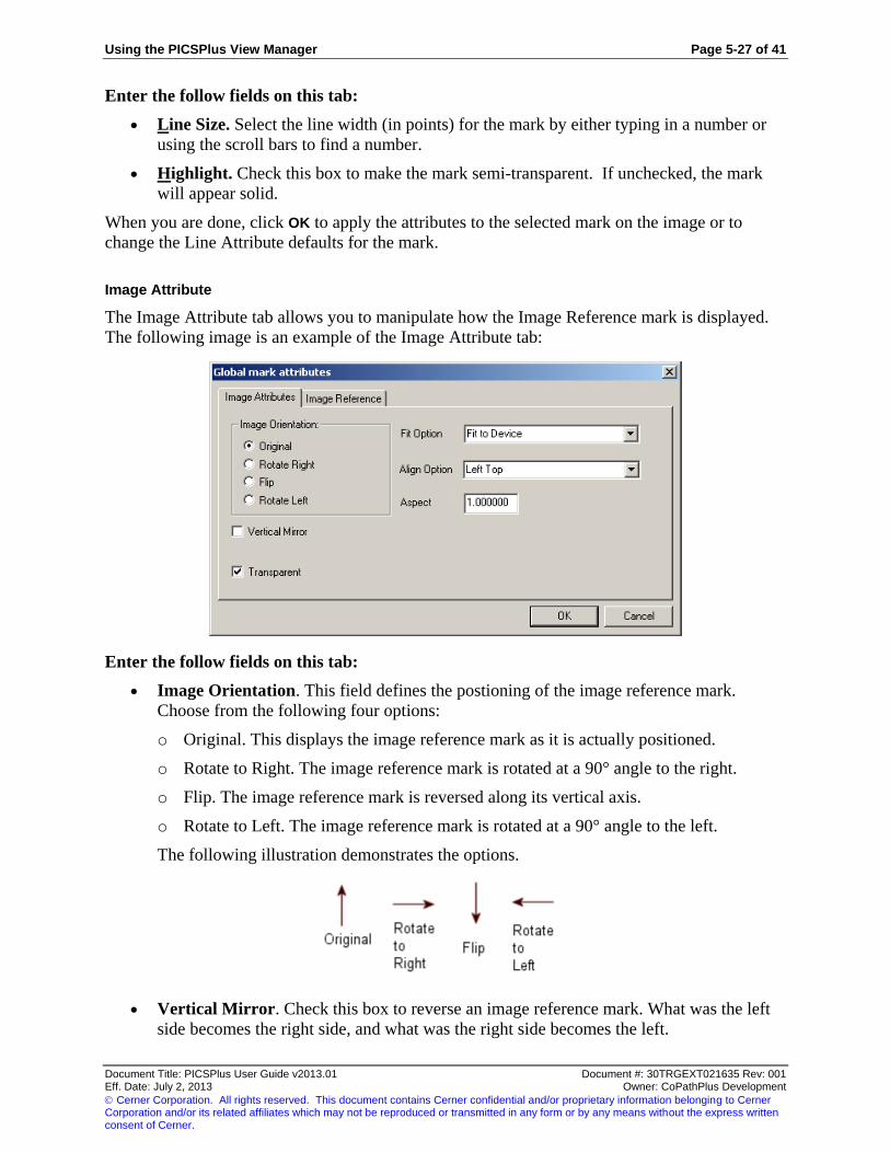
Using the PICSPlus View Manager Page 5-27 of 41
Document Title: PICSPlus User Guide v2013.01 Document #: 30TRGEXT021635 Rev: 001 Eff. Date: July 2, 2013 Owner: CoPathPlus Development
Cerner Corporation. All rights reserved. This document contains Cerner confidential and/or proprietary information belonging to Cerner Corporation and/or its related affiliates which may not be reproduced or transmitted in any form or by any means without the express written consent of Cerner.
Enter the follow fields on this tab:
Line Size. Select the line width (in points) for the mark by either typing in a number or
using the scroll bars to find a number.
Highlight. Check this box to make the mark semi-transparent. If unchecked, the mark
will appear solid.
When you are done, click OK to apply the attributes to the selected mark on the image or to
change the Line Attribute defaults for the mark.
Image Attribute
The Image Attribute tab allows you to manipulate how the Image Reference mark is displayed.
The following image is an example of the Image Attribute tab:
Enter the follow fields on this tab:
Image Orientation. This field defines the postioning of the image reference mark.
Choose from the following four options:
o Original. This displays the image reference mark as it is actually positioned.
o Rotate to Right. The image reference mark is rotated at a 90° angle to the right.
o Flip. The image reference mark is reversed along its vertical axis.
o Rotate to Left. The image reference mark is rotated at a 90° angle to the left.
The following illustration demonstrates the options.
Vertical Mirror. Check this box to reverse an image reference mark. What was the left
side becomes the right side, and what was the right side becomes the left.

Page 5-28 of 41 Using the PICSPlus View Manager
Document Title: PICSPlus User Guide v2013.01 Document #: 30TRGEXT021635 Rev: 001 Eff. Date: July 2, 2013 Owner: CoPathPlus Development
Cerner Corporation. All rights reserved. This document contains Cerner confidential and/or proprietary information belonging to Cerner Corporation and/or its related affiliates which may not be reproduced or transmitted in any form or by any means without the express written consent of Cerner.
Transparent. Check this box if you want the image reference mark to be transparent.
When the image is transparent, any white in the image becomes invisible so the image
beneath the image reference mark is visible.
Fit Option. This field defines how the image reference mark fits into the device
rectangle, which is the invisible frame in which the image appears. Choose one of the
following four options from the drop-down list box:
o Fit to Device. The image reference mark is scaled to fit both the width and height of
the device rectangle.
o Fit to Width. The image reference mark is scaled to fit the width of the device
rectangle.
o Fit to Height. The image reference mark is scaled to fit the height of the device
rectangle.
o Actual Size. The device rectangle is ignored and the image reference mark is scaled
1:1.
The following illustration is an example of a device rectangle.
Align Option. This field defines how the image reference mark is positioned horizontally
and vertically within the device rectangle. Choose one of the following from the drop-
down list box:
Aspect. This field defines the ratio of the width of an image reference mark to its height.
The following illustration displays how the aspect ratio setting changes the display of an
image reference mark.

Using the PICSPlus View Manager Page 5-29 of 41
Document Title: PICSPlus User Guide v2013.01 Document #: 30TRGEXT021635 Rev: 001 Eff. Date: July 2, 2013 Owner: CoPathPlus Development
Cerner Corporation. All rights reserved. This document contains Cerner confidential and/or proprietary information belonging to Cerner Corporation and/or its related affiliates which may not be reproduced or transmitted in any form or by any means without the express written consent of Cerner.
Image Reference Attribute
The Image Reference tab allows you to select an image from a file to display in the Image
Reference mark. The following image is an example of the Image Reference Attribute tab:
Enter the follow field on this tab:
Image File Name. Enter the directory and file name of the image that you want to use for the
image reference mark.
To search for the file, press the Browse…. button. The Browse Picture File window will appear.

Page 5-30 of 41 Using the PICSPlus View Manager
Document Title: PICSPlus User Guide v2013.01 Document #: 30TRGEXT021635 Rev: 001 Eff. Date: July 2, 2013 Owner: CoPathPlus Development
Cerner Corporation. All rights reserved. This document contains Cerner confidential and/or proprietary information belonging to Cerner Corporation and/or its related affiliates which may not be reproduced or transmitted in any form or by any means without the express written consent of Cerner.
You can only select bit-mapped images for the Image Reference mark. To ensure you are
selecting a valid image, you should select the Picture Files option for the Files of type field so
only image files with a file extension of bmp or dib will appear.
NOTE: If you are setting the defaults for a mark, the image reference on this tab will appear as the default image
reference each time the mark is created.
Protractor Attribute
The Protractor Attribute tab allows you to select the precision and the arc radius for the
Protractor mark. The following image is an example of the Protractor Attribute tab:

Using the PICSPlus View Manager Page 5-31 of 41
Document Title: PICSPlus User Guide v2013.01 Document #: 30TRGEXT021635 Rev: 001 Eff. Date: July 2, 2013 Owner: CoPathPlus Development
Cerner Corporation. All rights reserved. This document contains Cerner confidential and/or proprietary information belonging to Cerner Corporation and/or its related affiliates which may not be reproduced or transmitted in any form or by any means without the express written consent of Cerner.
Enter the follow fields on this tab:
Output Precision. Enter a value to determine precision of the protractor. If the number in
the box is two (2), then the precision will be to the second decimal place.
Arc Radius. Enter a value to represents the distance from the apex of the angle where the
arc will be drawn. This is a relative number and no unit of measure is available
(however, the number 100 is twice the distance from the apex as is the number 50).
When you are done, click OK to apply the attributes to the selected Protractor on the image or to
change the attribute defaults for the Protractor mark.
Text Attribute
There are two variations of the Text Attributes window. In the first, the Text Attribute tab
allows you to enter and edit the text in any marks that contain text, such as the Typed Text, Text
Stamp, or the Push Pin mark. The following image is an example of the Text Attribute tab:
The following image is an example of the Text Attribute tab for the Text Stamp tool.

Page 5-32 of 41 Using the PICSPlus View Manager
Document Title: PICSPlus User Guide v2013.01 Document #: 30TRGEXT021635 Rev: 001 Eff. Date: July 2, 2013 Owner: CoPathPlus Development
Cerner Corporation. All rights reserved. This document contains Cerner confidential and/or proprietary information belonging to Cerner Corporation and/or its related affiliates which may not be reproduced or transmitted in any form or by any means without the express written consent of Cerner.
Enter the follow fields on this tab:
The box on the top of the tab is where you enter the text that will be displayed in the
mark.
NOTE: If you are setting the defaults for a mark, the text on this tab will appear as the default text each time
the mark is created.
Wrap. Check this box to control the text flow in the mark. If this box is unchecked, the
text will continue on a single line.
Insert Date. Text Stamp only. Click this button to include the current date as text.
Appears as "%x" in the box, but will show up as the date on the image.
Insert Time. Text Stamp only. Click this button to include the current time as text.
Appears as "%X" in the box, but will show up as the time on the image.
When you are done, click OK to apply the attributes to the selected mark on the image.
The second variation of the Text Attributes display provides a mechanism to define a file path
and name to a text file saved on a local or networked drive. This parameter is used in the Text
From File mark. Define a .txt file on a local or networked drive first. Access the Text attributes
window within the Text From File Defaults configuration and enter the pathway to the defined
file or use the Browse button to locate it.

Using the PICSPlus View Manager Page 5-33 of 41
Document Title: PICSPlus User Guide v2013.01 Document #: 30TRGEXT021635 Rev: 001 Eff. Date: July 2, 2013 Owner: CoPathPlus Development
Cerner Corporation. All rights reserved. This document contains Cerner confidential and/or proprietary information belonging to Cerner Corporation and/or its related affiliates which may not be reproduced or transmitted in any form or by any means without the express written consent of Cerner.
When you are done, click OK to apply the attributes to the selected mark on the image.
Burning Marks
The Burn Marks feature allows you to permanently apply the mark to the image displayed in the
PICSPlus View Manager. Once the mark is burned into the image and the user exits the Image
Viewer (for that particular image), it cannot be removed, it becomes a permanent and integral
part of the image and is no longer a separate object. If you want the annotations to appear on the
report, you must burn them into the image.
To burn a mark on the image, click on the mark and press the Burn button on the Marks tab. To
restore a mark to a temporary state, click the Undo Burn button on the Marks tab before exiting
the View Manager. This will restore the mark to a temporary mark which will not appear on the
report and which you can delete from the image. To delete all the marks, click the Select All
button and then click the Burn button.
Process Tab
The Process tab contains tools that allow you to sharpen the image and to adjust how it appears
on the screen. The following illustration is an example of the Process tab:

Page 5-34 of 41 Using the PICSPlus View Manager
Document Title: PICSPlus User Guide v2013.01 Document #: 30TRGEXT021635 Rev: 001 Eff. Date: July 2, 2013 Owner: CoPathPlus Development
Cerner Corporation. All rights reserved. This document contains Cerner confidential and/or proprietary information belonging to Cerner Corporation and/or its related affiliates which may not be reproduced or transmitted in any form or by any means without the express written consent of Cerner.
The Process tab contains the following display adjustment tools:
Clarification Filter
Orientation
Crop to Selection
Only burned marks on the image display when you press the Process tab. If the mark is burned
on the image, any adjustments you make to the image will also apply to the mark. For example if
you have an arrow mark burned on the image and you rotate the image, the arrow will rotate with
the image. However, if you did not burn the mark onto the image, the arrow will not display on
the Process tab at all.
Clarification Filter
The Clarification Filter is used to sharpen mid to high contrast edges without enhancing the noise
normally present in digital images. This effect locates adjacent pixels within the radius you
specify, and it increases their contrast by the strength you select.
The Clarification Filter has two settings:
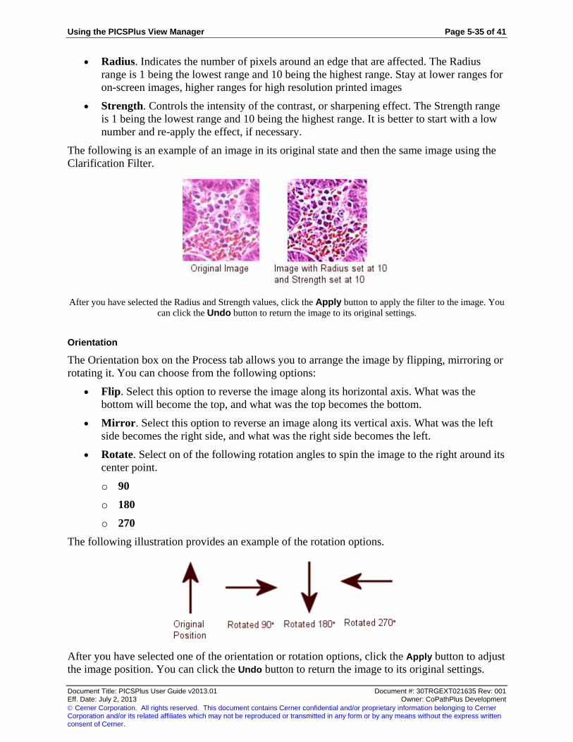
Using the PICSPlus View Manager Page 5-35 of 41
Document Title: PICSPlus User Guide v2013.01 Document #: 30TRGEXT021635 Rev: 001 Eff. Date: July 2, 2013 Owner: CoPathPlus Development
Cerner Corporation. All rights reserved. This document contains Cerner confidential and/or proprietary information belonging to Cerner Corporation and/or its related affiliates which may not be reproduced or transmitted in any form or by any means without the express written consent of Cerner.
Radius. Indicates the number of pixels around an edge that are affected. The Radius
range is 1 being the lowest range and 10 being the highest range. Stay at lower ranges for
on-screen images, higher ranges for high resolution printed images
Strength. Controls the intensity of the contrast, or sharpening effect. The Strength range
is 1 being the lowest range and 10 being the highest range. It is better to start with a low
number and re-apply the effect, if necessary.
The following is an example of an image in its original state and then the same image using the
Clarification Filter.
After you have selected the Radius and Strength values, click the Apply button to apply the filter to the image. You
can click the Undo button to return the image to its original settings.
Orientation
The Orientation box on the Process tab allows you to arrange the image by flipping, mirroring or
rotating it. You can choose from the following options:
Flip. Select this option to reverse the image along its horizontal axis. What was the
bottom will become the top, and what was the top becomes the bottom.
Mirror. Select this option to reverse an image along its vertical axis. What was the left
side becomes the right side, and what was the right side becomes the left.
Rotate. Select on of the following rotation angles to spin the image to the right around its
center point.
o 90
o 180
o 270
The following illustration provides an example of the rotation options.
After you have selected one of the orientation or rotation options, click the Apply button to adjust
the image position. You can click the Undo button to return the image to its original settings.

Page 5-36 of 41 Using the PICSPlus View Manager
Document Title: PICSPlus User Guide v2013.01 Document #: 30TRGEXT021635 Rev: 001 Eff. Date: July 2, 2013 Owner: CoPathPlus Development
Cerner Corporation. All rights reserved. This document contains Cerner confidential and/or proprietary information belonging to Cerner Corporation and/or its related affiliates which may not be reproduced or transmitted in any form or by any means without the express written consent of Cerner.
Crop to Selection
Users can manually crop images using the PICSPlus Image Viewer. Before cropping an image, it
is recommended that a duplicate be made of the original image using the Duplicate option,
available on the Edit tab on the PICSPlus Report Manager and the PICSPlus Image Gallery.
Note: Images can also be cropped automatically by configuring the Attachment Type Dictionary. Refer to the
“Attachment Type Dictionary” in the PICSPlus Dictionaries section.
To crop the image manually, place the mouse pointer at a corner of the area to be cropped and
drag to make the selection. A crop rectangle will appear on the image, and the area inside the
crop rectangle is shaded. The crop rectangle can be resized and moved by using the mouse
pointer. In the Crop to Selection area, click the Apply button to crop the selection.
The image below displays an example of the crop rectangle around the image being cropped.
Press the Undo button to return the image to it its original state, if desired.
If you have made any changes to the image, CoPathPlus will display a message asking if you
want to save the image when you close the Image Viewer window.
Colors Tab
The Colors tab provides you with tools for adjusting the color in the image displayed on the
PICSPlus View Manager.
The following illustration is an example of the Colors tab:
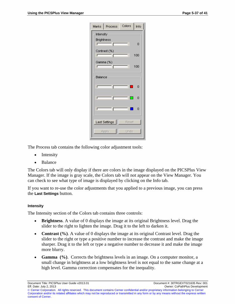
Using the PICSPlus View Manager Page 5-37 of 41
Document Title: PICSPlus User Guide v2013.01 Document #: 30TRGEXT021635 Rev: 001 Eff. Date: July 2, 2013 Owner: CoPathPlus Development
Cerner Corporation. All rights reserved. This document contains Cerner confidential and/or proprietary information belonging to Cerner Corporation and/or its related affiliates which may not be reproduced or transmitted in any form or by any means without the express written consent of Cerner.
The Process tab contains the following color adjustment tools:
Intensity
Balance
The Colors tab will only display if there are colors in the image displayed on the PICSPlus View
Manager. If the image is gray scale, the Colors tab will not appear on the View Manager. You
can check to see what type of image is displayed by clicking on the Info tab.
If you want to re-use the color adjustments that you applied to a previous image, you can press
the Last Settings button.
Intensity
The Intensity section of the Colors tab contains three controls:
Brightness. A value of 0 displays the image at its original Brightness level. Drag the
slider to the right to lighten the image. Drag it to the left to darken it.
Contrast (%). A value of 0 displays the image at its original Contrast level. Drag the
slider to the right or type a positive number to increase the contrast and make the image
sharper. Drag it to the left or type a negative number to decrease it and make the image
more blurry.
Gamma (%). Corrects the brightness levels in an image. On a computer monitor, a
small change in brightness at a low brightness level is not equal to the same change at a
high level. Gamma correction compensates for the inequality.

Page 5-38 of 41 Using the PICSPlus View Manager
Document Title: PICSPlus User Guide v2013.01 Document #: 30TRGEXT021635 Rev: 001 Eff. Date: July 2, 2013 Owner: CoPathPlus Development
Cerner Corporation. All rights reserved. This document contains Cerner confidential and/or proprietary information belonging to Cerner Corporation and/or its related affiliates which may not be reproduced or transmitted in any form or by any means without the express written consent of Cerner.
The color adjustments will appear as you move the slides, but will not be applied until you press
the Apply button. To return the image to its original settings before the adjustments are applied,
press the Reset button. After you apply the adjustments, you can press the Undo button to return
the image to its original settings.
Balance
The Brightness section of the Color tab contains three slides to adjust the red, green and blue
levels in the image displayed on PICSPlus View Manager. By adjusting the levels of red, green,
and blue in an image or selection, you can change its overall color cast and correct color balance
problems.
To reduce the amount of color in an image, you can either increase its opposite color or reduce
the amount of the adjacent colors (on the color wheel). For example, to color correct an image
containing too much yellow, either increase the amount of blue or decrease the amount of red
and green.
Move the color slide to the right to increase the level of the color or move the slide to the left to
decrease the level. On the right of the slide, a number will appear to indicate the level of the
adjusted color.
The color adjustments will appear as you move the slides, but will not be applied until you press
the Apply button. To return the image to its original settings before the adjustments are applied,
press the Reset button. After you apply the adjustments, you can press the Undo button to return
the image to its original settings.
Info Tab
The Info tab displays the image parameter and edit permission information for the image
displayed in the PICSPlus View Manager. The following illustration is an example of the Info
tab.

Using the PICSPlus View Manager Page 5-39 of 41
Document Title: PICSPlus User Guide v2013.01 Document #: 30TRGEXT021635 Rev: 001 Eff. Date: July 2, 2013 Owner: CoPathPlus Development
Cerner Corporation. All rights reserved. This document contains Cerner confidential and/or proprietary information belonging to Cerner Corporation and/or its related affiliates which may not be reproduced or transmitted in any form or by any means without the express written consent of Cerner.
The Info tab has two sections:
Image Parameters
Edit Permissions
Image Parameters
The Image Parameter section of the Info tab displays the following read-only information:
Type. Indicates the type of image. There are 3 types:
o Black/White
o Gray Scale
o Color
Note: If you burn a mark contain color onto a gray scale image, when you save the image, the type will change
to Color. In addition, the size of the file will increase to accommodate the colors now contained in the
image.
Bits per Pixel. Indicates the color depth of the image. Bits per Pixel is the number of bits
used to represent the color of a single pixel in an image. As the bits per pixel increase, so
does the size of the file.
o 1 bit - Black/White
o 8 bit -Gray Scale
o 8 bit - Color

Page 5-40 of 41 Using the PICSPlus View Manager
Document Title: PICSPlus User Guide v2013.01 Document #: 30TRGEXT021635 Rev: 001 Eff. Date: July 2, 2013 Owner: CoPathPlus Development
Cerner Corporation. All rights reserved. This document contains Cerner confidential and/or proprietary information belonging to Cerner Corporation and/or its related affiliates which may not be reproduced or transmitted in any form or by any means without the express written consent of Cerner.
o 24 bit - Color
Width (pixels). Indicates the width of the image by pixel.
Height (pixels). Indicates the height of the image by pixel.
Size (bytes). Indicates the size of the image file by bytes.
Edit Permissions
The Edit Permissions section of the Info tab displays the following permissions:
Mode. Indicates if the image is in an editable mode. Edit indicates that you can make
changes to the image. Read Only indicates that you can only view the image.
Colors. Indicates if the image contains colors. If Yes is displayed, the image contains
colors. If No is displayed, the image only contains black and white.
Marks. Indicates if you can make marks on the image. If an image contains colors and
you can edit the image, you can make marks on the image. If it is a black and white
image, you will not be able to make marks on the image.
Process. Indicates if you can use the tools on the Process tab. If the image contains colors
and you can edit the image, you will be able to use the tools on the Process tab. If it is a
black and white image and you can edit the image, you will only be able to use the
orientation tools on the Process tab.

Using the PICSPlus View Manager Page 5-41 of 41
Document Title: PICSPlus User Guide v2013.01 Document #: 30TRGEXT021635 Rev: 001 Eff. Date: July 2, 2013 Owner: CoPathPlus Development
Cerner Corporation. All rights reserved. This document contains Cerner confidential and/or proprietary information belonging to Cerner Corporation and/or its related affiliates which may not be reproduced or transmitted in any form or by any means without the express written consent of Cerner.
This page was intentionally left blank.

PICSPlus Express Capture Page 6-1 of 4
Document Title: PICSPlus User Guide v2013.01 Document #: 30TRGEXT021635 Rev: 001 Eff. Date: July 2, 2013 Owner: CoPathPlus Development
Cerner Corporation. All rights reserved. This document contains Cerner confidential and/or proprietary information belonging to Cerner Corporation and/or its related affiliates which may not be reproduced or transmitted in any form or by any means without the express written consent of Cerner.
Chapter 6: PICSPlus Express Capture
PICSPlus Express Capture Introduction
To address pathologist requests to acquire routine images using fewer keystrokes, an Express
Capture feature is offered. Express Capture allows a user to acquire images without opening the
PICSPlus Imager Gallery or Report Gallery. Use of Express Capture assumes the following:
Images are acquired via the workstation’s Default Import Action (acquisition method).
Acquired images use the workstation’s default Import Type and Template.
Images are not annotated.
Acquired images will be visually confirmed at some other point in the workflow. For
example, if they are placed on patient reports by default, they will be viewed when the
report is examined during Signout.
Express Capture uses alternative objects to the previously used Image Gallery and Report
Gallery Application User Object (buttons). This set of window objects offers dual functionality;
each gallery button can be used in two different capacities. When the Express Capture object is
used, the updated display shows an Express check box to the right of the Gallery button. When
the Express check box is clear, the Image Gallery and Report Gallery buttons display and
function according to established conventions, opening the designated PICSPlus Gallery.
However, when the Express check box is checked, the Gallery button becomes an image
acquisition button specific to the default method for the workstation.
Both the Image Gallery and Report Gallery buttons show the number of images already acquired
on a case regardless of the Express check box setting.
A user may "check on" the Express check box to quickly acquire images using workstation
default parameters without opening the Image Gallery or Report Gallery. Should a particular
image require annotation or update to any default parameter, simply click on the check in the
Express field to clear it and use the Gallery button to open the Image Gallery or Report Gallery
according to pre-established conventions.

Page 6-2 of 4 PICSPlus Express Capture
Document Title: PICSPlus User Guide v2013.01 Document #: 30TRGEXT021635 Rev: 001 Eff. Date: July 2, 2013 Owner: CoPathPlus Development
Cerner Corporation. All rights reserved. This document contains Cerner confidential and/or proprietary information belonging to Cerner Corporation and/or its related affiliates which may not be reproduced or transmitted in any form or by any means without the express written consent of Cerner.
Tip!: If some of your pathologists plan to acquire images via the Express Capture feature in Electronic Signout, it
will be more efficient for them to open the Electronic Signout activity in the Edit mode rather than the Report mode.
This alternative can be configured using the Display Report before Editing System Setting located in the Electronic
Signout Category. If this configuration is only efficient for some of your pathologists, consider use of the
Workstation Group System Setting Override for the Display Report before Editing setting.
The Express check box value will persist on a per workstation basis. Specifically if the last
person to use the Image Gallery or Report Gallery button on a particular workstation leaves the
"check" on, the Express check box will be checked the next time someone uses that same
workstation.

PICSPlus Express Capture Page 6-3 of 4
Document Title: PICSPlus User Guide v2013.01 Document #: 30TRGEXT021635 Rev: 001 Eff. Date: July 2, 2013 Owner: CoPathPlus Development
Cerner Corporation. All rights reserved. This document contains Cerner confidential and/or proprietary information belonging to Cerner Corporation and/or its related affiliates which may not be reproduced or transmitted in any form or by any means without the express written consent of Cerner.
Setting Up PICSPlus Express Capture
To set up PICSPlus Express Capture:
1) Paint the following buttons with the Express Capture feature onto the CoPathPlus
windows :
o Image Gallery Button on the PICSPlus Image Entry/Edit window
o Report Gallery Select Images Button on the PICSPlus Report Image Select window.
For information on additional windows you can paint the buttons, refer to "CoPathPlus
Form Sequences Eligible for PICSPlus Activities"
2) Set the Default Import Action from the PICSPlus Gallery Manager Option Menu or
PICSPlus Report Manager Option Menu.
3) Click the Express check mark on the window on which you painted the buttons with the
Express Capture feature.
You can then begin to quickly capture images in PICSPlus by clicking the Import From button.
PICSPlus Express Capture Window Painting Requirement
In order to implement the PICSPlus Express Capture feature, it is necessary to repaint your
windows to use one of the Application User Objects that include the add-on Express Capture
capability. The original Application User objects will continue to function according to
previously established conventions and do not include the Express check box. Update your
windows to use the respective Application User Objects for the Image Gallery and Select Images
buttons as desired.
Follow standard window painting guidelines to replace gallery objects, save, compile, accept,
and rebuild the applicable windows.
Note: If you have not been trained on window painting or are uncomfortable attempting it, you may pursue an
Arrangement Letter to have Cerner CoPathPlus personnel to window paint for you, or may opt to attend CoPathPlus
Customizer Training. Customizer Training is offered monthly; courses are alternately held in the Waltham office
and on the web. These classes are suitable for first time attendees as well as for students that need "refresher"
training. Due to the hands-on nature of the Customizer Training, our strong recommendation is that you attend this
class in person if possible, especially if you are a first time attendee. However, for those with travel constraints, the
web course alternative is offered.
Image Gallery Button With Express Capture Option
The Image Gallery buttons can be painted onto different CoPathPlus specimen activities.
However, only one model of this button (either the original or the Express Capture model) can be
included on any specific window. Activities that support the Image Gallery button include
Accession Entry/Edit, Gross Description Entry Edit, Final Diagnosis Entry/Edit, Hot Seat
Diagnosis Entry/Edit, Procedure/Addendum Entry/Edit, Post Signout Edit, and PICSPlus Image
Entry/Edit. When selected from the Insert an Application User Object tool in the Window
Painter, the original button is labeled "PICSPlus Imager gallery button" and the Express Capture
button is labeled "PICSPlus button for express gallery".

Page 6-4 of 4 PICSPlus Express Capture
Document Title: PICSPlus User Guide v2013.01 Document #: 30TRGEXT021635 Rev: 001 Eff. Date: July 2, 2013 Owner: CoPathPlus Development
Cerner Corporation. All rights reserved. This document contains Cerner confidential and/or proprietary information belonging to Cerner Corporation and/or its related affiliates which may not be reproduced or transmitted in any form or by any means without the express written consent of Cerner.
Report Gallery Select Images Button With Express Capture Option
Both the original and Express Capture Select Images button may be painted onto the Signout
(Electronic), Signout (Manual), and PICSPlus Report Image Select activities. As with the Image
Gallery button, you may not use both the original and the Express Capture model of the Report
Gallery Select Images button on the same window; select one model or the other of this button.
When selected from the Insert an Application User Object tool in the Window Painter, the
original button is labeled “PICSPlus button to select images for reports” and the Express Capture
button is labeled “PICSPlus button for express report”.

PICSPlus Dictionaries Page 9-1 of 18
Document Title: PICSPlus User Guide v2013.01 Document #: 30TRGEXT021635 Rev: 001 Eff. Date: July 2, 2013 Owner: CoPathPlus Development
Cerner Corporation. All rights reserved. This document contains Cerner confidential and/or proprietary information belonging to Cerner Corporation and/or its related affiliates which may not be reproduced or transmitted in any form or by any means without the express written consent of Cerner.
Chapter 9: PICSPlus Dictionaries
PICSPlus dictionaries are structures that store and maintain PICSPlus information.
Refer to the following for more information:
Dictionary Building Sequence Order
PICSPlus Server Dictionary
Attachment Type Dictionary
PICSPlus Parameters Dictionary
PICSPlus Template Dictionary
Imaging Device Type Dictionary
Note: Although the PICSPlus Keyword Dictionary appears in the menu, keyword functionality is not currently
implemented. This dictionary is intended for future use.
Dictionary Building Sequence Order
The PICSPlus dictionaries are interdependent and therefore should be built in a particular order. You should follow
the recommended building sequence, specified in the table below.
Order Dictionary
1 PICSPlus Server Dictionary
2 Attachment Type Dictionary
3 PICSPlus Parameter Dictionary
4 PICSPlus Template Dictionary

Page 9-2 of 18 PICSPlus Dictionaries
Document Title: PICSPlus User Guide v2013.01 Document #: 30TRGEXT021635 Rev: 001 Eff. Date: July 2, 2013 Owner: CoPathPlus Development
Cerner Corporation. All rights reserved. This document contains Cerner confidential and/or proprietary information belonging to Cerner Corporation and/or its related affiliates which may not be reproduced or transmitted in any form or by any means without the express written consent of Cerner.
PICSPlus Server Dictionary
PICSPlus Server Dictionary lets you to create new Image Server definitions. Each dictionary
entry contains a unique name field that identifies the Image Server, and the UNC path to a shared
image storage directory where the images will be stored.
CoPathPlus determines which PICSPlus Server is used for image storage via a system setting
default or a Workstation Group-specific System Setting Override. The default PICSPlus server
is defined in the System Setting entitled "PICSPlus Image Repository". All images will be
written to this repository unless the acquisition workstation belongs to a Workstation Group that
has an override for this setting. In that case, the Image Repository defined in the respective
Workstation Group will be used for image storage. Refer to "Workstation Groups" in the
CoPathPlus System Manager Guide for further information about System Setting Overrides.
How to Add a New PICSPlus Server Dictionary Entry
Perform the following steps to add a new entry to the PICSPlus Server Dictionary:
1) Press Dictionaries on the CoPathPlus Application Manager.
See "How Do I Access a Dictionary" for more detailed instructions and information about creating and accessing dictionaries
2) Select the PICSPlus Server Dictionary from the list presented on the right side of the
Application Manager.
3) Press New on the Select a PICSPlus Server Window.
4) Fill in the following fields on the Name tab:
o Name. Enter a unique designation for this dictionary entry. Although you can enter
up to 100 alphanumeric characters, we recommend that you keep the keyword name
concise so that it displays completely in the image parameters list box.
o Abbr. Enter a unique, short code that you can use to quickly recall this dictionary
entry while you are entering data on a window. You can enter up to 15 alphanumeric
characters.
o Description. Enter text that describes this PICSPlus keyword entry. You can enter
up to 255 alphanumeric characters.
o Inactive. Select this check box if you want to make this entry not active. Inactive
entries will not appear on a lookup window, though they will appear at the end of an
accelerated drop-down list enclosed in angle brackets (e.g., <West 1>), which
indicate that the entries are not active and cannot be used. A clear check box means
that the entry is active.
o Path. Enter the fully-qualified file path to the shared network directory that holds the
PICSPlus repository (for example:
\\filebos1\mis\transfer\PICSPlus_shared\pics_images_v2.4\). This is the directory
where PICSPlus service files and thumbnail files will be stored. It should end with a
final back-slash character.

PICSPlus Dictionaries Page 9-3 of 18
Document Title: PICSPlus User Guide v2013.01 Document #: 30TRGEXT021635 Rev: 001 Eff. Date: July 2, 2013 Owner: CoPathPlus Development
Cerner Corporation. All rights reserved. This document contains Cerner confidential and/or proprietary information belonging to Cerner Corporation and/or its related affiliates which may not be reproduced or transmitted in any form or by any means without the express written consent of Cerner.
5) Lookup Values. Enter any lookup value that you want for this dictionary item, if
necessary. You may find it useful to enter two types of manual lookup values: one short
and the other more descriptive. Short lookup values are easier to remember and allow for
faster data entry. Descriptive lookup values help users when they are doing a partial
lookup. Note that Name and Abbr. automatically become lookup values for each entry.
6) Enter any information on the Notes tab that helps the CoPathPlus System Manager or the
dictionary administrator keep track of the history of a dictionary. For example, the way a
dictionary entry was set up, or when and why an edit was made to an entry.

Page 9-4 of 18 PICSPlus Dictionaries
Document Title: PICSPlus User Guide v2013.01 Document #: 30TRGEXT021635 Rev: 001 Eff. Date: July 2, 2013 Owner: CoPathPlus Development
Cerner Corporation. All rights reserved. This document contains Cerner confidential and/or proprietary information belonging to Cerner Corporation and/or its related affiliates which may not be reproduced or transmitted in any form or by any means without the express written consent of Cerner.
Attachment Type Dictionary
PICSPlus allows your site to acquire images to print reports, archive information, and/or to
reference for teaching purposes. The Attachment Type Dictionary is a baseline CoPathPlus
Dictionary that is used for specific PICSPlus applications as well.
For example, a site might reference a library of images of anatomical diagrams, scan in
requisitions and reports and/or digitally photograph specimens and their slides (a digital camera
can be mounted above the grossing table or above a microscope) and then associate these images
with a specimen as attachments.
The Attachment Type Dictionary is used to categorize image types for the purpose of defaulting
and linking images to specimen reports. This dictionary references the attachment class, which is
the mode of acquisition of the attachment. Each attachment class is associated with a third-party
application that your site uses to acquire, review, edit and in some cases, delete attachments
belonging to that attachment class.
The Attachment Type Dictionary can also be used by for automatic cropping of images.
Automatic cropping is useful for document images that consistently have the same border size.
Values entered into the Page Border Removal Attributes, on the Report tab, are used by
CoPathPlus to crop the border automatically. When the image is inserted into the patient report,
it is resized to fit into the space between the header and footer. Removing some of the border
allows a larger version of the image to be displayed in the report.
It is common to refer to image-related attachments as simply specimen images or to use "image"
synonymously with "attachment".
Attachment Type Dictionary Attributes
While the Attachment Type dictionary will come preloaded with several representative entries,
each site will have to build the bulk of the dictionary.
The number of entries in the Attachment Type Dictionary will vary from site to site. Some sites
may choose to have as few entries as possible, while other sites may have many entries in order
to take advantage of the variations allowed.
Refer to "Attachment Type Dictionary Prerequisites" to learn what your site should consider
before building the Attachment Type Dictionary.
CoPathPlus allows you to automatically link an attachment of a particular type to patient reports
(e.g., Working Draft, Final Report, Procedure Report) through the To Report Type(s) field under
Automatic Links on the Reports tab in this dictionary. Then, when an image attachment is
acquired, it is automatically linked to all unsigned-out reports with a report type selected in this
field. There are some factors your site should consider when deciding whether or not to set up a
link to a report:
1) If the attachment type is for procedures in general, do not set up linking because it will
link an image to all procedures.
PICSPlus Dictionaries Page 9-5 of 18
Document Title: PICSPlus User Guide v2013.01 Document #: 30TRGEXT021635 Rev: 001 Eff. Date: July 2, 2013 Owner: CoPathPlus Development
Cerner Corporation. All rights reserved. This document contains Cerner confidential and/or proprietary information belonging to Cerner Corporation and/or its related affiliates which may not be reproduced or transmitted in any form or by any means without the express written consent of Cerner.
If the attachment type is for a specific procedure and it is rare that a specimen has more than one of these procedures, link the attachment type to a Procedure Report in the To Report Type(s) field and then identify the procedure in the To Procedure field.
2) If the attachment type is for any addendum, do not set up linking because it will link an
attachment to all addenda.
3) Compare the average number of images acquired for an attachment type to the number
that is usually printed on reports. If you end up doing more work by unlinking
attachments, then do not set up the automatic linking feature.
For example, a site may only acquire images that it intends to include on reports. In this case, the site would set up automatic links. Another site might acquire lots of images, some of which print on reports while others are used to build a database for research and teaching. This site might not set up automatic links.
NOTE: If a report's template does not include this attachment type, any attachment of this type linked to the report
will not print. Refer to "Patient Report Painter" in the Cerner CoPathPlus Online Tools Guide or the Cerner
CoPathPlus Tools Training Manual for more information on the Patient Report Painter.
In addition, if an attachment type is set up to automatically link to a report type but, when the attachment of this type
is acquired, there is no report for that report type, then no linking can occur. For example, procedure attachments
may be acquired before the procedure is ordered in CoPathPlus. In this case, the user will have to manually link the
attachment after the report has been created.
Refer to "How to Add a New Attachment Type Dictionary Entry" to learn how to create an entry
for this dictionary
Attachment Type Dictionary Prerequisites
Before building the Attachment Type Dictionary, your site should compile a list of all the kinds
of image acquiring it plans to do. Keep in mind the following tips when building this dictionary:
1) Create a list of basic attachment types to be acquired (e.g., Gross, Micro, Procedure).
2) Answer the following questions for each of these basic types and break out a basic type
into more specific types, if needed:
o Is the mode of acquisition (i.e., the attachment class) the same for all the attachments?
If not, create one attachment type per attachment class.
o Will all images be included on reports? If not, create one attachment type for those
that are included on reports and another for those that are not.
o Are the display width and height the same for all images of this type? If not, create
one attachment type for each set of display measurements.
o Should all images of this type automatically be linked to reports, and to the same
reports? If not, create one attachment type for each report setup.
Then you must consider how many workstations need to do what, and which workstations can
provide more than one service. For example, you might have a workstation that is hooked up to
a microscope and camera, as well as to a scanner.

Page 9-6 of 18 PICSPlus Dictionaries
Document Title: PICSPlus User Guide v2013.01 Document #: 30TRGEXT021635 Rev: 001 Eff. Date: July 2, 2013 Owner: CoPathPlus Development
Cerner Corporation. All rights reserved. This document contains Cerner confidential and/or proprietary information belonging to Cerner Corporation and/or its related affiliates which may not be reproduced or transmitted in any form or by any means without the express written consent of Cerner.
How to Add a New Attachment Type Dictionary Entry
Perform the following steps to add a new entry to the Attachment Type Dictionary:
1) Press Dictionaries on the Application Manager.
See "How Do I Access a Dictionary" for more detailed instructions and information about creating and accessing dictionaries
2) Select the Attachment Type Dictionary from the list presented on the right side of the
Application Manager.
3) Press New on the Select a Dictionary Entry Window.
The Attachment Type Dictionary has the following tabs:
Name Tab
Reports Tab
Notes Tab
Attachment Type Dictionary - Name Tab
NOTE: The first five fields on the Name tab are common ones for all dictionaries. If you have not read Name Tab
in Dictionary Basics, you should do that first as you will find more general information about these fields there.
Information provided here for these fields serves as a reminder and can include more specific details as to how they
pertain to this dictionary. Any fields after the Lookup Values field on the Name tab are unique to this dictionary's
Name tab.
Fill in the fields on the Name tab in the Attachment Type Dictionary as follows:
1) Name. Enter a unique attachment type designation for each dictionary entry. Remember
that you can enter up to 100 alphanumeric characters.
2) Abbr. Enter a unique, short code that you can use to quickly recall this dictionary entry
while you are entering data on a window. Remember that you can enter up to 10
alphanumeric characters.
3) Description. Enter text that describes this attachment type. Remember that you can
enter up to 255 alphanumeric characters.
4) Inactive. Select this check box if you want to make this entry not active. Inactive entries
will not appear on a lookup window, though they will appear at the end of an accelerated
drop-down list enclosed in angle brackets (e.g., <West 1>), which indicate that the entries
are not active and cannot be used. A clear check box means that the entry is active.
5) Lookup Values. Enter any lookup value that you want for this dictionary item, if
necessary. You may find it useful to enter two types of manual lookup values: one short
and the other more descriptive. Short lookup values are easier to remember and allow for
faster data entry. Descriptive lookup values help users when they are doing a partial
lookup.
6) Attachment Class. Select an attachment class for this attachment type. For use with
PICSPlus, you will always select the "Image in PICSPlus" option.
WARNING: The attachment class should not be changed once there are attachments on file that point to this
attachment type. The attachment class drives the data input when an attachment is acquired for a specimen,
as well as how it is viewed and printed.

PICSPlus Dictionaries Page 9-7 of 18
Document Title: PICSPlus User Guide v2013.01 Document #: 30TRGEXT021635 Rev: 001 Eff. Date: July 2, 2013 Owner: CoPathPlus Development
Cerner Corporation. All rights reserved. This document contains Cerner confidential and/or proprietary information belonging to Cerner Corporation and/or its related affiliates which may not be reproduced or transmitted in any form or by any means without the express written consent of Cerner.
7) Sort Order. Enter the order in which you want this image to appear in reports.
Attachment Type Dictionary - Reports Tab
Fill in the fields on the Reports tab in the Attachment Type Dictionary as follows:
1) Characteristics. Specify the characteristics of this attachment type.
o Allow on Reports. Select this check box if attachments of this type can be painted
onto printed patient reports. Certain attachments may not be appropriate on printed
reports (e.g., sound files). If this check box is not selected, the remaining fields on
this tab are ignored by CoPathPlus.
o Display Width. Enter the width of the display (in inches) for attachments of this type
when printed on reports. The default width is two (2) inches.
o Display Height. Enter the height of the display (in inches) for attachments of this
type when printed on reports. The default height is two (2) inches.
NOTE 1: If the actual size of the attachment is greater than the display size, CoPathPlus scales down the
attachment to the size specified in the above two fields but preserves the aspect ratio. If the actual size of
the attachment is less than the display size, CoPathPlus uses the actual size of the attachment in height and
uses the actual size plus white space to make up the specified Display Width.
NOTE 2: If your site uses Visual Writer as the text entry tool, the dimensions of the attachment image
display must be 2 in. by 2 in. so that the caption aligns correctly under the attachment on patient reports.
This allows a maximum of three attachments across the width of the report. Furthermore, attachment
images should be at least 250 pixels wide, and should have the width as the greatest dimension. For
example, an image 640 pixels wide by 480 pixels high will display better on the report than one 480 wide
by 640 high. Finally, any attachment that cannot conform to these rules should be placed last in the image
order.
o Print Quality. This field allows users to select the print quality of a PICSPlus image.
The range is 1 to 10, with 1 being the fastest printing with the lowest quality and 10
being the slowest printing with the highest quality. System Managers will have to
experiment with the image size and the quality of the image in the report to get the
appropriate image size/quality relation that fits their hardware specs and requirements
of printed reports.
2) Automatic Links. You use these fields to facilitate the automatic linking of image
attachments to printed reports. You can link attachments of a particular type to one,
many, or none of a specimen's reports. Refer to "Attachment Type Dictionary Attributes"
to determine if your site should set up an automatic link(s) for this attachment type.
o To Report Type(s). Select the report type(s) to which an attachment of this type
should automatically be linked. This link can be overridden for an individual
specimen attachment through the Attachments tab in a specimen activity.
3) Page Border Removal Attributes (Inches). You use these fields to facilitate the
automatic cropping if image attachments in printed reports. This is useful for documents
that consistently have the same amount of white space around the border that can be
cropped without affecting the image. Removing some of the border allows a larger
version of the image to be displayed in the report.
o Source Page Dimensions (Required). Enter the Width and Height of the document
image that will be cropped in the Source Page Dimensions fields. For example, if the

Page 9-8 of 18 PICSPlus Dictionaries
Document Title: PICSPlus User Guide v2013.01 Document #: 30TRGEXT021635 Rev: 001 Eff. Date: July 2, 2013 Owner: CoPathPlus Development
Cerner Corporation. All rights reserved. This document contains Cerner confidential and/or proprietary information belonging to Cerner Corporation and/or its related affiliates which may not be reproduced or transmitted in any form or by any means without the express written consent of Cerner.
attachment type was for requisitions printed on US standard letter size paper, the
Width would be 8.5 (in inches) and the Length would be 11.
o Border Dimensions (Enter at least one). Enter the height and/or width in inches that
should be cropped from the border in the Border Dimensions fields. For cropping to
occur, at least one measurement must be entered in the Top, Bottom, Left or Right
fields. For example, the border could be cropped evenly by a quarter of an inch by
entering .25 in each field or if there was an extra inch of white space on the bottom of
the page, only the bottom of the page could be cropped by entering 1 in the Bottom
field.
When the attachment is inserted into the report, CoPathPlus will crop it using the
dimensions entered in the Attachment Type Dictionary. When cropping an image using
this method, the original image will not be affected.
The image below illustrates how the Border Dimension fields correspond to the borders
on the document image.
Attachment Type Dictionary - Notes Tab
Enter any information on the Notes tab in the Attachment Type Dictionary that helps the
CoPathPlus System Manager or the dictionary administrator keep track of the history of a
PICSPlus Dictionaries Page 9-9 of 18
Document Title: PICSPlus User Guide v2013.01 Document #: 30TRGEXT021635 Rev: 001 Eff. Date: July 2, 2013 Owner: CoPathPlus Development
Cerner Corporation. All rights reserved. This document contains Cerner confidential and/or proprietary information belonging to Cerner Corporation and/or its related affiliates which may not be reproduced or transmitted in any form or by any means without the express written consent of Cerner.
dictionary (e.g., why a dictionary entry was set up the way it was, when and why an edit was
made to an entry).

Page 9-10 of 18 PICSPlus Dictionaries
Document Title: PICSPlus User Guide v2013.01 Document #: 30TRGEXT021635 Rev: 001 Eff. Date: July 2, 2013 Owner: CoPathPlus Development
Cerner Corporation. All rights reserved. This document contains Cerner confidential and/or proprietary information belonging to Cerner Corporation and/or its related affiliates which may not be reproduced or transmitted in any form or by any means without the express written consent of Cerner.
PICSPlus Parameters Dictionary
Image Parameters are data elements or characteristics associated to PICSPlus images. In
addition to assisting in image identification, parameters are also used to record and retain
information specific to each particular image.
Values for many image parameters are automatically captured. PICSPlus recognizes
elements such as image type and acquisition device based on your configuration of the
PICSPlus system. Other parameters such as Captured By and Capture Date default according
to standard CoPathPlus auditing features. Still other parameter information such as Image
Format and Size are automatically determined when each image is acquired.
The PICSPlus Parameters Dictionary is pre-loaded with numerous standard image parameters
already defined. If your institution would like to capture some image parameter that has not
been pre-defined, you may add it directly to this dictionary.
Some pre-defined records in the Parameters Dictionary are keyed and will not be editable.
How to Add a New PICSPlus Parameter Dictionary Entry
Perform the following steps to add a new entry to the PICSPlus Parameter Dictionary:
1) Press Dictionaries on the CoPathPlus Application Manager.
See "How Do I Access a Dictionary" for more detailed instructions and information about creating and accessing dictionaries
2) Select the PICSPlus Parameter Dictionary from the list presented on the right side of the
Application Manager.
3) Press New on the Select a PICSPlus Parameter window.
The PICSPlus Parameter Dictionary has the following tabs:
Name Tab
Notes Tab
PICSPlus Parameter Dictionary - Name Tab
This illustration shows a sample Name tab in the PICSPlus Parameter Dictionary.

PICSPlus Dictionaries Page 9-11 of 18
Document Title: PICSPlus User Guide v2013.01 Document #: 30TRGEXT021635 Rev: 001 Eff. Date: July 2, 2013 Owner: CoPathPlus Development
Cerner Corporation. All rights reserved. This document contains Cerner confidential and/or proprietary information belonging to Cerner Corporation and/or its related affiliates which may not be reproduced or transmitted in any form or by any means without the express written consent of Cerner.
1) Name. Enter a unique designation for this dictionary entry. Although you can enter up
to 100 alphanumeric characters, we recommend that you keep the keyword name concise
so that it displays completely in the image parameters list box.
2) Abbr. Enter a unique, short code that you can use to quickly recall this dictionary entry
while you are entering data on a window. You can enter up to 15 alphanumeric
characters.
3) Description. Enter text that describes this PICSPlus keyword entry. You can enter up to
255 alphanumeric characters.
4) Inactive. Select this check box if you want to make this entry not active. Inactive entries
will not appear on a lookup window, though they will appear at the end of an accelerated
drop-down list enclosed in angle brackets (e.g., <West 1>), which indicate that the entries
are not active and cannot be used. A clear check box means that the entry is active.
5) Non-user parameter. This check box is enabled if this data is automatically captured
and users may not alter the entry. This is typically only used for Cerner CoPathPlus
defined parameters.
6) Type of Data: Select the item from the drop-down list that defines the value type for this
parameter.
7) Choices. This free text field is used to stipulate choices when applicable. This field is
usually left empty.
8) Lookup Values. Enter any lookup value that you want for this dictionary item, if
necessary. You may find it useful to enter two types of manual lookup values: one short
and the other more descriptive. Short lookup values are easier to remember and allow for
faster data entry. Descriptive lookup values help users when they are doing a partial
lookup. Note that Name and Abbr. automatically become lookup values for each entry.
PICSPlus Parameter Dictionary - Notes Tab
This illustration shows a partial view of a sample Notes tab in the PICSPlus Parameter
Dictionary.

Page 9-12 of 18 PICSPlus Dictionaries
Document Title: PICSPlus User Guide v2013.01 Document #: 30TRGEXT021635 Rev: 001 Eff. Date: July 2, 2013 Owner: CoPathPlus Development
Cerner Corporation. All rights reserved. This document contains Cerner confidential and/or proprietary information belonging to Cerner Corporation and/or its related affiliates which may not be reproduced or transmitted in any form or by any means without the express written consent of Cerner.
Enter any information on the Notes tab that helps the CoPathPlus System Manager or the
dictionary administrator keep track of the history of a dictionary. For example, the way a
dictionary entry was set up, or when and why an edit was made to an entry.
PICSPlus Dictionaries Page 9-13 of 18
Document Title: PICSPlus User Guide v2013.01 Document #: 30TRGEXT021635 Rev: 001 Eff. Date: July 2, 2013 Owner: CoPathPlus Development
Cerner Corporation. All rights reserved. This document contains Cerner confidential and/or proprietary information belonging to Cerner Corporation and/or its related affiliates which may not be reproduced or transmitted in any form or by any means without the express written consent of Cerner.
PICSPlus Template Dictionary
The PICSPlus Template Dictionary lets you create different templates to associate the image
parameters in the Parameters for Selected Item list box that is found in the PICSPlus
Acquisition Manager, Gallery Manager, and Report Manager. You may want to show only
certain parameters for an image, depending on the situation. For example, you could create a
Grossing Template that is specific to the CoPathPlus Gross Description Entry/Edit activity. The
parameters may be different for the Final Diagnosis Entry/Edit activity window.
The Templates are linked to the various activity windows through the Window Painter. When
painting a window to include a PICSPlus object (i.e. adding the Image Capture, Image Gallery or
Report Gallery Application User Object) to the window, you will also define properties for this
object. Define the template from the PICSPlus Template Dictionary appropriate for the window.
Define "Button Push" for "When to Load Images". For a more detailed description of the use of
the Window Painter please refer to the "Window Painter" section in the CoPathPlus Online Tools
Guide.
A special template configuration may be defined in PICSPlus Template Dictionary to
automatically provide sequential titles for imported images. Refer to the "Parameters Tab" for
more information.
NOTE: PICSPlus templates should be created only after a detailed analysis of the workflow. Setting templates up
incorrectly could cause a significant performance downgrade. Cerner CoPathPlus recommends you use the option
of "Button Push" rather than "Specimen Load" when defining the properties of each PICSPlus Application User
Object (button). The templates that are predefined in the PICSPlus Template Dictionary are created as examples
only, and should not be used as actual templates.
How to Add a New PICSPlus Template Dictionary Entry
Perform the following steps to add a new entry to the PICSPlus Template Dictionary:
1) Press Dictionaries on the CoPathPlus Application Manager.
See "How Do I Access a Dictionary" for more detailed instructions and information about creating and accessing dictionaries
2) Select the PICSPlus Template Dictionary from the list presented on the right side of the
Application Manager.
3) Press Search on the Select a PICSPlus Template window.
A list of the templates will be displayed in the list box.
4) Select the template of choice and double click or select Run from the command buttons.
The PICSPlus Template Dictionary has the following tabs:
Name Tab
Parameters Tab
Notes Tab

Page 9-14 of 18 PICSPlus Dictionaries
Document Title: PICSPlus User Guide v2013.01 Document #: 30TRGEXT021635 Rev: 001 Eff. Date: July 2, 2013 Owner: CoPathPlus Development
Cerner Corporation. All rights reserved. This document contains Cerner confidential and/or proprietary information belonging to Cerner Corporation and/or its related affiliates which may not be reproduced or transmitted in any form or by any means without the express written consent of Cerner.
PICSPlus Template Dictionary - Name Tab
This illustration shows a sample Name tab in the PICSPlus Template Dictionary.
1) Name. Enter a unique designation for this dictionary entry. Although you can enter up
to 100 alphanumeric characters, we recommend that you keep the keyword name concise
so that it displays completely in the image parameters list box.
2) Abbr. Enter a unique, short code that you can use to quickly recall this dictionary entry
while you are entering data on a window. You can enter up to 15 alphanumeric
characters.
3) Description. Enter text that describes this PICSPlus keyword entry. You can enter up to
255 alphanumeric characters.
4) Inactive. Select this check box if you want to make this entry not active. Inactive entries
will not appear on a lookup window, though they will appear at the end of an accelerated
drop-down list enclosed in angle brackets (e.g., <West 1>), which indicate that the entries
are not active and cannot be used. A clear check box means that the entry is active.
Parameters Tab
The following illustration shows a sample Parameters tab in the PICSPlus Template Dictionary.
The Parameters tab is where you define the list of parameters for the template. Refer to the
"PICSPlus Parameter Dictionary" for more information about image parameters.
A feature specific to the Title parameter is the ability to automatically provide sequential titles
for imported images. In the Default Value field adjacent to the Parameter of "Title", define a
standard value plus the string of {{seq}}. Sequential numbers will be inserted where the {{seq}}
placeholder is denoted. For example, on a Microscopic Image, the Default Value of "Micro
{{seq}}" might be defined. The first microscopic image imported on a specimen would receive
the title of "Micro 1". The second microscopic image imported would receive the title of "Micro
2", and so forth. The following illustration provides an example.

PICSPlus Dictionaries Page 9-15 of 18
Document Title: PICSPlus User Guide v2013.01 Document #: 30TRGEXT021635 Rev: 001 Eff. Date: July 2, 2013 Owner: CoPathPlus Development
Cerner Corporation. All rights reserved. This document contains Cerner confidential and/or proprietary information belonging to Cerner Corporation and/or its related affiliates which may not be reproduced or transmitted in any form or by any means without the express written consent of Cerner.
A system setting entitled Image Title Sequence # Style offers an alternative for sequential letters
to be used within this naming convention.
The Image Title Sequence # Style System Setting is located in the Imaging Category. Leave
this setting at its default value of "N" to continue using a number as the sequential enumerator.
Change the value to an "A" if you prefer to use an alpha enumerator.
PICSPlus Template Dictionary - Notes Tab
This illustration shows a partial view of a sample Notes tab in the PICSPlus Template
Dictionary.
Enter any information on the Notes tab that helps the CoPathPlus System Manager or the
dictionary administrator keep track of the history of a dictionary. For example, the way a
dictionary entry was set up, or when and why an edit was made to an entry.

Page 9-16 of 18 PICSPlus Dictionaries
Document Title: PICSPlus User Guide v2013.01 Document #: 30TRGEXT021635 Rev: 001 Eff. Date: July 2, 2013 Owner: CoPathPlus Development
Cerner Corporation. All rights reserved. This document contains Cerner confidential and/or proprietary information belonging to Cerner Corporation and/or its related affiliates which may not be reproduced or transmitted in any form or by any means without the express written consent of Cerner.
Imaging Device Type Dictionary
The Imaging Device Type Dictionary support the different types of imaging devices or slide
scanners a site might use in connection with PICSLink and Digital Slide Imaging.
How to Add a New Imaging Device Type Dictionary
Perform the following steps to add a new entry to the Imaging Device Type Dictionary:
1) Press Dictionaries on the Application Manager.
2) Select the Imaging Device Type Dictionary from the list presented on the right side of the
Application Manager.
3) Press New on the Select a Dictionary Entry Window.
Refer to "How Do I Access a Dictionary" for more detailed instructions and information about accessing dictionaries.
4) The Imaging Device Type Dictionary has the following tabs:
o Name Tab
o Details Tab
o Notes Tab
Name Tab
This illustration shows a sample Name tab in the Imaging Device Type Dictionary.
1) Name. Enter a unique designation for this dictionary entry. Although you can enter up
to 100 alphanumeric characters, we recommend that you keep the keyword name concise
so that it displays completely in the image parameters list box.
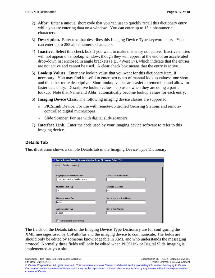
PICSPlus Dictionaries Page 9-17 of 18
Document Title: PICSPlus User Guide v2013.01 Document #: 30TRGEXT021635 Rev: 001 Eff. Date: July 2, 2013 Owner: CoPathPlus Development
Cerner Corporation. All rights reserved. This document contains Cerner confidential and/or proprietary information belonging to Cerner Corporation and/or its related affiliates which may not be reproduced or transmitted in any form or by any means without the express written consent of Cerner.
2) Abbr. Enter a unique, short code that you can use to quickly recall this dictionary entry
while you are entering data on a window. You can enter up to 15 alphanumeric
characters.
3) Description. Enter text that describes this Imaging Device Type keyword entry. You
can enter up to 255 alphanumeric characters.
4) Inactive. Select this check box if you want to make this entry not active. Inactive entries
will not appear on a lookup window, though they will appear at the end of an accelerated
drop-down list enclosed in angle brackets (e.g., <West 1>), which indicate that the entries
are not active and cannot be used. A clear check box means that the entry is active.
5) Lookup Values. Enter any lookup value that you want for this dictionary item, if
necessary. You may find it useful to enter two types of manual lookup values: one short
and the other more descriptive. Short lookup values are easier to remember and allow for
faster data entry. Descriptive lookup values help users when they are doing a partial
lookup. Note that Name and Abbr. automatically become lookup values for each entry.
6) Imaging Device Class. The following imaging device classes are supported:
o PICSLink Device. For use with remote-controlled Grossing Stations and remote-
controlled digital microscopes.
o Slide Scanner. For use with digital slide scanners.
7) Interface Link. Enter the code used by your imaging device software to refer to this
imaging device.
Details Tab
This illustration shows a sample Details tab in the Imaging Device Type Dictionary.
The fields on the Details tab of the Imaging Device Type Dictionary are for configuring the
XML messages used by CoPathPlus and the imaging device to communicate. The fields are
should only be edited by someone knowledgeable in XML and who understands the messaging
protocol. Normally these fields will only be edited when PICSLink or Digital Slide Imaging is
implemented at your site.

Page 9-18 of 18 PICSPlus Dictionaries
Document Title: PICSPlus User Guide v2013.01 Document #: 30TRGEXT021635 Rev: 001 Eff. Date: July 2, 2013 Owner: CoPathPlus Development
Cerner Corporation. All rights reserved. This document contains Cerner confidential and/or proprietary information belonging to Cerner Corporation and/or its related affiliates which may not be reproduced or transmitted in any form or by any means without the express written consent of Cerner.
1) Imaging Device Handler Object. Enter the name of the vendor-specific Device Handler
Object. This object has to be inherited from v_nuo_img_device_handler_base.
2) Launch Parameter Prefix. Enter the launch parameter prefix to start the device EXE
file.
3) Message Root Tag. Enter the Root tag name for the device communication XML
message. If left blank, it will be defaulted to "Message".
4) Start File Extension. Enter the extension of device start file. If left blank, it will be
defaulted to "XML".
5) Message Image Tag. Enter the Image tag name for the device communication XML
message. If left blank, it will be defaulted to "Image".
6) Server Name or IP Address. Enter the Server Name or IP address if required by the
Imaging Device.
7) Authentication Tag. Enter the Authentication tag name for the device communication
XML message. If left blank, it will be defaulted to "Login".
8) Server Port Name. Enter the Authentication tag name for the device communication
XML message. If left blank, it will be defaulted to "Login".
9) Authentication Encode Flag. Click this check box to activate encoding of the
authentication string.
Notes Tab
Enter any information on the Notes tab that helps the CoPathPlus System Manager or the
dictionary administrator keep track of the history of a dictionary. For example, the way a
dictionary entry was set up, or when and why an edit was made to an entry.

PICSPlus Management Reports Page 8-1 of 4
Document Title: PICSPlus User Guide v2013.01 Document #: 30TRGEXT021635 Rev: 001 Eff. Date: July 2, 2013 Owner: CoPathPlus Development
Cerner Corporation. All rights reserved. This document contains Cerner confidential and/or proprietary information belonging to Cerner Corporation and/or its related affiliates which may not be reproduced or transmitted in any form or by any means without the express written consent of Cerner.
Chapter 8: PICSPlus Management Reports
This guide provides descriptions of the following management reports, which are specific to
PICSPlus.
Case Diagnostics Folder
PICSPlus Case Detail
PICSPlus Image Search/Natural Language
PICSPlus Image Search/SNOMED
PICSPlus Images with Annotations
Logs
PICSPlus Acquisition Workstations
The following reports are described in the PICSPlus Maintenance Module section:
Image Servers Activity Report
Acquisition Workstation Activity Report
Detect Lost Images by Specimen Number
Detect Lost Images by Date Range
In addition, there are a number of management reports that are described in the Cerner
CoPathPlus User Guide. For more information, refer to "Report Descriptions" in that guide.
TIP! You can access any of the reports described here by placing the report in your Personal Menu and double-
clicking on it from there.
NOTE: You can run your site-created InfoMaker reports through the CoPathPlus InfoMaker Wizard. The
InfoMaker Wizard is a CoPathPlus application feature that lets you easily specify different types of selection criteria
for all reports using InfoMaker. People with permission can link site-created InfoMaker reports to the InfoMaker
Wizard through the InfoMaker Item Entry/Edit item found within the Folders and Items folder under the Setup
command button. Consult your System Manager for more information about this capability. To learn about this
item, refer to "InfoMaker Item Entry/Edit" in the "Setup" section of the Cerner CoPathPlus System Manager Guide.
For more information on reports, refer to the "Reports" section of the Cerner CoPathPlus User
Guide.
Accessing the PICSPlus Management Reports
To access the PICSPlus management reports in CoPathPlus:
1) Press the Reports command button on the CoPathPlus Application Manager.

Page 8-2 of 4 PICSPlus Management Reports
Document Title: PICSPlus User Guide v2013.01 Document #: 30TRGEXT021635 Rev: 001 Eff. Date: July 2, 2013 Owner: CoPathPlus Development
Cerner Corporation. All rights reserved. This document contains Cerner confidential and/or proprietary information belonging to Cerner Corporation and/or its related affiliates which may not be reproduced or transmitted in any form or by any means without the express written consent of Cerner.
A list of folders (categories of reports) appears on the right side of the Application Manager.
2) Double-click on the Case Diagnostic Reports folder or double-click on the Logs folder.
A list of available reports or items available within that folder appears.
3) Double-click on the report you want to open.
Running the PICSPlus Management Reports
Once you choose the PICSPlus management report you want to run, as specified in "Accessing
the PICSPlus Management Reports", the InfoMaker Wizard for the report you chose appears.
The InfoMaker Wizard is a CoPathPlus application feature that lets you easily specify different
types of selection criteria for all reports using InfoMaker.
NOTE: You can schedule reports to run using the CoPathPlus Schedule Manager.
The following topics refer to selecting PICSPlus specific criteria for PICSPlus Management
Reports. For more information on configuring, viewing and printing the reports refer to the
following topics in the Cerner CoPathPlus User Guide:
Running the Management Reports
Data Fields and Selection Criteria
Viewing and Printing the Management Reports

PICSPlus Management Reports Page 8-3 of 4
Document Title: PICSPlus User Guide v2013.01 Document #: 30TRGEXT021635 Rev: 001 Eff. Date: July 2, 2013 Owner: CoPathPlus Development
Cerner Corporation. All rights reserved. This document contains Cerner confidential and/or proprietary information belonging to Cerner Corporation and/or its related affiliates which may not be reproduced or transmitted in any form or by any means without the express written consent of Cerner.
Case Diagnostic Reports
The following PICSPlus Reports are located in the Case Diagnostic Report Folder:
PICSPlus Case Detail
PICSPlus Image Search/Natural Language
PICSPlus Image Search/SNOMED
PICSPlus Images with Annotations
PICSPlus Case Detail
The PICSPlus Case Detail report captures all cases with PICSPlus images. Retrieval arguments
are accession date, specimen class, part type, attachment type, and capture person. Detail
information is grouped by specimen number and includes accession date, patient name, and
MRN. The second group is attachment type and displays attachment type, title, description, who
captured, and capture date. The number of images per attachment type is indicated.
PICSPlus Image Search/Natural Language
The PICSPlus Image Search/Natural Language report is a modification of the standard Natural
Language report with additional logic requiring the case to have one or more PICSPlus images.
Retrieval arguments are accession date, signout date, specimen class, text search, text type to
print, age, gender, part type, and attachment type. The detail includes specimen number,
accession date, signout date, patient demographics, final diagnosis, primary pathologist, and
primary cytotech, when present.
PICSPlus Image Search/SNOMED
This report is a modification of the standard report SNOMED II Search No Race report with the
additional requirement to include one or more PICSPlus images. It also includes the additional
retrieval arguments of Part Type and Attachment Type. The Detail area is grouped by specimen
number, with accession date, signout date, and patient demographics. Detail data also includes
SNOMED codes and the final diagnosis.
PICSPlus Images with Annotations
The PICSPlus Images with Annotations report captures cases with PICSPlus images that contain
annotations. Retrieval arguments are accession date, specimen class, part type, and attachment
type. Detail information includes specimen number, accession date, patient name, attachment
type, attachment title, and description. The total number of images for each case, summary
calculations for total images, and summary calculations for total cases are also presented.

Page 8-4 of 4 PICSPlus Management Reports
Document Title: PICSPlus User Guide v2013.01 Document #: 30TRGEXT021635 Rev: 001 Eff. Date: July 2, 2013 Owner: CoPathPlus Development
Cerner Corporation. All rights reserved. This document contains Cerner confidential and/or proprietary information belonging to Cerner Corporation and/or its related affiliates which may not be reproduced or transmitted in any form or by any means without the express written consent of Cerner.
Logs
The following PICSPlus report is located in the Logs folder:
PICSPlus Acquisition Workstations
PICSPlus Acquisition Workstations
PICSPlus Acquisition Workstations will search Workstation Set-up for all workstations that are
enabled for PICSPlus acquisition or annotation activity. Workstations are enabled only for the
PICSPlus Gallery will not be included on this report. The name of each enabled workstation is
presented along with the list of licensed PICSPlus add-ons as enabled in the Workstation Setup
function. Use this log to track workstations using a PICSPlus license.

PICSLink Page 9-1 of 6
Document Title: PICSPlus User Guide v2013.01 Document #: 30TRGEXT021635 Rev: 001 Eff. Date: July 2, 2013 Owner: CoPathPlus Development
Cerner Corporation. All rights reserved. This document contains Cerner confidential and/or proprietary information belonging to Cerner Corporation and/or its related affiliates which may not be reproduced or transmitted in any form or by any means without the express written consent of Cerner.
Chapter 9: PICSLink
PICSLink Overview
Part of the CoPathPlus Telepathology strategy, PICSLink allows PICSPlus to launch stand-alone
imaging devices to capture images, image documents and metadata generated by imaging
devices. PICSLink enables users to take advantage of features such as measurements,
calculations, remote-controlled Grossing Stations and remote-controlled digital microscopes.
The following diagram displays the PICSLink workflow.
Using PICSLink
Steps for using PICSLink:
1) Setup the Device. The device must be compliant with PICSLink communication
specifications. Refer to the PICSPlus Implementation Manual for more information on
what imaging devices are compliant with PICSLink.
2) Install PICSLink as an add-on to a PICSPlus acquisition station in the Workstation Setup
activity. Your site needs to have an available acquisition station license to install
PICSLink. Please contact Cerner CoPathPlus to if you would like to purchase additional
PICSPlus acquisition licenses for your site.
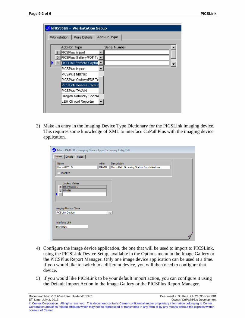
Page 9-2 of 6 PICSLink
Document Title: PICSPlus User Guide v2013.01 Document #: 30TRGEXT021635 Rev: 001 Eff. Date: July 2, 2013 Owner: CoPathPlus Development
Cerner Corporation. All rights reserved. This document contains Cerner confidential and/or proprietary information belonging to Cerner Corporation and/or its related affiliates which may not be reproduced or transmitted in any form or by any means without the express written consent of Cerner.
3) Make an entry in the Imaging Device Type Dictionary for the PICSLink imaging device.
This requires some knowledge of XML to interface CoPathPlus with the imaging device
application.
4) Configure the image device application, the one that will be used to import to PICSLink,
using the PICSLink Device Setup, available in the Options menu in the Image Gallery or
the PICSPlus Report Manager. Only one image device application can be used at a time.
If you would like to switch to a different device, you will then need to configure that
device.
5) If you would like PICSLink to be your default import action, you can configure it using
the Default Import Action in the Image Gallery or the PICSPlus Report Manager.
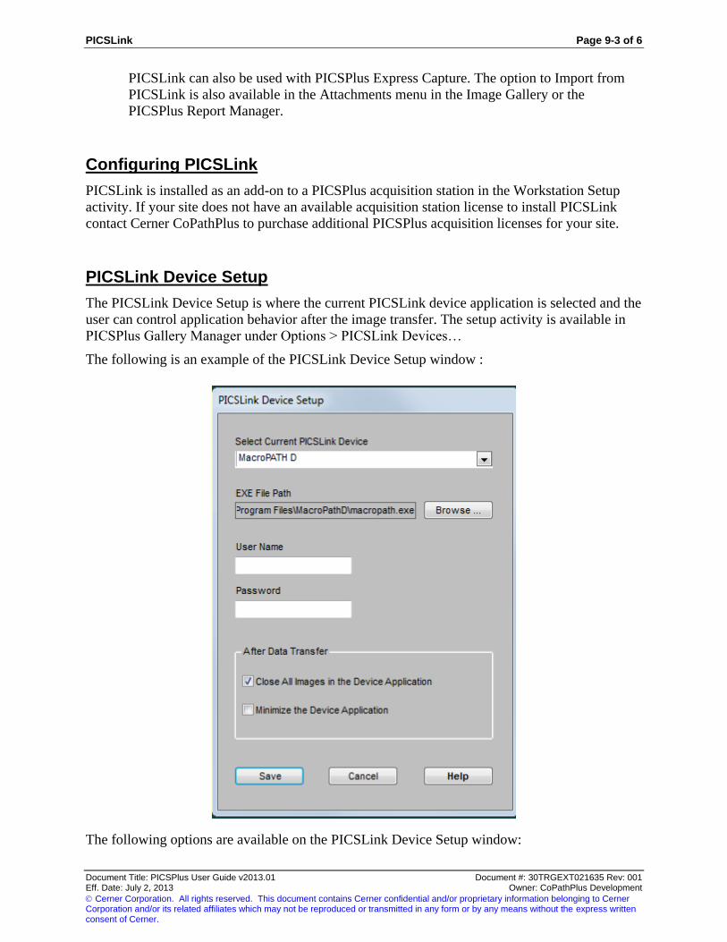
PICSLink Page 9-3 of 6
Document Title: PICSPlus User Guide v2013.01 Document #: 30TRGEXT021635 Rev: 001 Eff. Date: July 2, 2013 Owner: CoPathPlus Development
Cerner Corporation. All rights reserved. This document contains Cerner confidential and/or proprietary information belonging to Cerner Corporation and/or its related affiliates which may not be reproduced or transmitted in any form or by any means without the express written consent of Cerner.
PICSLink can also be used with PICSPlus Express Capture. The option to Import from
PICSLink is also available in the Attachments menu in the Image Gallery or the
PICSPlus Report Manager.
Configuring PICSLink
PICSLink is installed as an add-on to a PICSPlus acquisition station in the Workstation Setup
activity. If your site does not have an available acquisition station license to install PICSLink
contact Cerner CoPathPlus to purchase additional PICSPlus acquisition licenses for your site.
PICSLink Device Setup
The PICSLink Device Setup is where the current PICSLink device application is selected and the
user can control application behavior after the image transfer. The setup activity is available in
PICSPlus Gallery Manager under Options > PICSLink Devices…
The following is an example of the PICSLink Device Setup window :
The following options are available on the PICSLink Device Setup window:

Page 9-4 of 6 PICSLink
Document Title: PICSPlus User Guide v2013.01 Document #: 30TRGEXT021635 Rev: 001 Eff. Date: July 2, 2013 Owner: CoPathPlus Development
Cerner Corporation. All rights reserved. This document contains Cerner confidential and/or proprietary information belonging to Cerner Corporation and/or its related affiliates which may not be reproduced or transmitted in any form or by any means without the express written consent of Cerner.
Select Current PICSLink Device. Select a PICSLink Device from the drop-down menu.
The list of available devices is populated from the Imaging Device Type Dictionary,
described above.
EXE File Path. Click the Browse button to link to the EXE file for the PICSLink Device
software.
User Name and Password. If required by the PICSLink Device, enter a user name and
password so CoPathPlus can communicate with the PICSLink Device software.
After Data Transfer:
o Close All Images in the Device Application. Select this option if you want the
image acquired through the image device to close after it has transferred to
CoPathPlus. If you do not select this option, you will need to manually close the
images through the image device software.
o Minimize the Device Application. Select this option if you want the window
displaying the imaging device software to minimize after the data has transferred to
CoPathPlus.
PICSLink Automatic Acquisition of Image Documents
The PICSLink feature can be used for the transfer of image analysis reports along with image
snapshots. Image analysis reports can be supplied by compatible vendor-specific applications in
bitmap, TIFF, JPEG, or PDF form.
To use PICSLink to automatic acquire image documents:
1) Follow the steps outlined in "Using PICSLink" to setup PICSLink for your workstation to
acquire image documents.
2) In the PICSPlus Report Manager, set PICSLink to be the default import action.
3) Select the Options Menu from the Report Manager and select Default Import Template.
Chose the "Import from PICSLink" option.
4) In the PICSPlus Import Template Manager, select a default import template and default
report template.

PICSLink Page 9-5 of 6
Document Title: PICSPlus User Guide v2013.01 Document #: 30TRGEXT021635 Rev: 001 Eff. Date: July 2, 2013 Owner: CoPathPlus Development
Cerner Corporation. All rights reserved. This document contains Cerner confidential and/or proprietary information belonging to Cerner Corporation and/or its related affiliates which may not be reproduced or transmitted in any form or by any means without the express written consent of Cerner.
Refer to the PICSPlus Implementation Guide for instructions on how to define a default
report template.
5) Use the stand-alone imaging device to acquire image documents through CoPathPlus.
Page 9-6 of 6 PICSLink
Document Title: PICSPlus User Guide v2013.01 Document #: 30TRGEXT021635 Rev: 001 Eff. Date: July 2, 2013 Owner: CoPathPlus Development
Cerner Corporation. All rights reserved. This document contains Cerner confidential and/or proprietary information belonging to Cerner Corporation and/or its related affiliates which may not be reproduced or transmitted in any form or by any means without the express written consent of Cerner.
This page was intentionally left blank.

Digital Slide Imaging Page 10-1 of 6
Document Title: PICSPlus User Guide v2013.01 Document #: 30TRGEXT021635 Rev: 001 Eff. Date: July 2, 2013 Owner: CoPathPlus Development
Cerner Corporation. All rights reserved. This document contains Cerner confidential and/or proprietary information belonging to Cerner Corporation and/or its related affiliates which may not be reproduced or transmitted in any form or by any means without the express written consent of Cerner.
Chapter 10: Digital Slide Imaging
Introduction
Digital Slides are increasingly being used by sites to improve workflow by making slides
available after they are digitally scanned for storage, access, and analysis. Digital Slide Imaging
in CoPathPlus is designed to work seamlessly in the pathologist’s workflow by making it
available from Specimen activities. When combined with PICSLink, Digital Slide Imaging can
capture snapshots from digital slides into PICSPlus and can launch digital slide viewers from the
PICSPlus Gallery. Through the Advanced Barcoding and Tracking (AB&T) solution, slides are
tracked in CoPathPlus and multiple vendor-specific digital slide viewers can be launched
simultaneously from Specimen activities.
Digital Slide Imaging Workflow
The specimen is accessioned and proceeds through the sites typical specimen workflow. Slides
are labeled with a unique identifier in 2D barcode. The slides are then scanned in the digital slide
scanner which reads the barcode on the slide. Communication is initiated with CoPathPlus to
exchange patient/specimen information and the status of the slide. The slide is then attached to
the specimen and is ready for review by the pathologist. The pathologist can see the list of digital
slides associated with the specimen on the Digital Slide tab, which can be painted on specimen
activities, such as the Final Diagnosis Entry/Edit activity. Using PICSLink, the pathologist can
take snapshots of the digital slide to attach images the patient report.
Configuring Digital Slide Imaging
Sites interested in Digital Slide Imaging will need:
Cerner CoPathPlus activates the system setting
Vendor-specific digital slide viewer(s) compatible with the CoPathPlus Digital Slide
communication specifications. Contact Cerner CoPathPlus for more information on
compatible digital slide viewers.
Digital Slide HL7 interface for communication between CoPathPlus and the digital slide
viewer
CoPathPlus Advanced Barcoding and Tracking solution for tracking the slides using a 2D
barcode in CoPathPlus

Page 10-2 of 6 Digital Slide Imaging
Document Title: PICSPlus User Guide v2013.01 Document #: 30TRGEXT021635 Rev: 001 Eff. Date: July 2, 2013 Owner: CoPathPlus Development
Cerner Corporation. All rights reserved. This document contains Cerner confidential and/or proprietary information belonging to Cerner Corporation and/or its related affiliates which may not be reproduced or transmitted in any form or by any means without the express written consent of Cerner.
PICSPlus and PICSLink (optional) for capturing snapshots from digital slides along with
metadata into PICSPlus and launching vendor-specific digital slide viewers from the
PICSPlus image gallery
If you do not currently have the Digital Slide Imaging solution but would like to pursue it, please
contact your Client Works Sales Executive.
Imaging Device Type Dictionary
Digital Slide Imaging, in addition to PICSLink, uses the Imaging Device Type Dictionary for
supporting devices with CoPathPlus. Below is an example of a digital slide entry for use with
Digital Slide Imaging. When selecting an Imaging Device Class for a digital slide, choose the
Slide Scanner option. Refer to "Imaging Device Type Dictionary " in the PICSPlus Dictionaries
section for more information
The following is an example of the Imaging Device Type Dictionary for a slide scanner entry:
Digital Slide Device Setup
The Digital Slide Device Setup is where the current digital slide device application is selected
and the user can control application behavior after the image transfer. The setup activity is
available under File > Browse Items.
The following is an example of the Digital Slide Device Setup window:

Digital Slide Imaging Page 10-3 of 6
Document Title: PICSPlus User Guide v2013.01 Document #: 30TRGEXT021635 Rev: 001 Eff. Date: July 2, 2013 Owner: CoPathPlus Development
Cerner Corporation. All rights reserved. This document contains Cerner confidential and/or proprietary information belonging to Cerner Corporation and/or its related affiliates which may not be reproduced or transmitted in any form or by any means without the express written consent of Cerner.
The following options are available on the Digital Slide Device Setup window:
Select Current Digital Slide Device. Select a digital slide viewer from the drop-down
menu. The list of available devices is populated from the Imaging Device Type
Dictionary, described above.
EXE File Path. Click the Browse button to link to the EXE file for the digital slide
viewer application. CoPathPlus uses this connection to communicate with the digital slide
viewer.
User Name and Password. If required by the digital slide viewer, enter a user name and
password so CoPathPlus can communicate with the digital slide viewer.
After Data Transfer:
o Close All Images in the Device Application. Select this option if you want the
image acquired through the image device to close after it has transferred to
CoPathPlus. If you do not select this option, you will need to manually close the
images through the image device software.
o Minimize the Device Application. Select this option if you want the window
displaying the imaging device software to minimize after the data has transferred to
CoPathPlus.

Page 10-4 of 6 Digital Slide Imaging
Document Title: PICSPlus User Guide v2013.01 Document #: 30TRGEXT021635 Rev: 001 Eff. Date: July 2, 2013 Owner: CoPathPlus Development
Cerner Corporation. All rights reserved. This document contains Cerner confidential and/or proprietary information belonging to Cerner Corporation and/or its related affiliates which may not be reproduced or transmitted in any form or by any means without the express written consent of Cerner.
Digital Slide Imaging in Specimen Activities
Sites with Digital Slide Imaging enabled can paint the Digital Slide tab on specimen activity
windows. In the following example, the tab has been added to the Final Diagnosis Entry/Edit
activity. From this window, the pathologist can view digital slides attached to the case.
The following is an example of Final Diagnosis Entry/Edit activity with a Digital Slide tab
painted on it.
In the detailed view, as displayed above, each slide for a part is displayed on the tab. If the slide
is digital, an icon displays that indicates this can be selected for viewing. If an displays, it
indicates that this digital slide is not available for viewing. If "none" appears, it indicates that the
slide is not digital and therefore cannot be viewed from this window. The detailed view also
displays the block, stain, status, date that the status was last updated, and the slide viewer from
which the digital slide was obtained. If only one viewer is in use, the Viewer field would not
display.
If a detailed view is not necessary, the display can be compressed by pressing the Collapse
button. If the detailed view is desired again, the Expand button is pressed to display information
similar to the above example. The individual scans can also be expanded or contracted by
clicking the +/- to the left of the scan.

Digital Slide Imaging Page 10-5 of 6
Document Title: PICSPlus User Guide v2013.01 Document #: 30TRGEXT021635 Rev: 001 Eff. Date: July 2, 2013 Owner: CoPathPlus Development
Cerner Corporation. All rights reserved. This document contains Cerner confidential and/or proprietary information belonging to Cerner Corporation and/or its related affiliates which may not be reproduced or transmitted in any form or by any means without the express written consent of Cerner.
On this window, you can do the following:
To select scans: click on an individual scan to select it or use Ctrl+Click to select
multiple scans or to deselect a scan. When a scan is selected, it is highlighted, as the
image above demonstrates. To load an individual scan into the digital slide viewer,
double-click on it.
After selecting the scans: use the Load Selected button to view the highlighted scans or
the Load All button to view all the scans. The Load Selected and Load All buttons also
display the number of scans they will load to alert the user if a large number of scans
have been selected.
Sites using Digital Slide Imaging with PICSPlus and PICSLink will also have the following
options on the Digital Slide tab:
Preload PICSPlus Image Gallery to accept captured images. Check this button to
allow PICSPlus to capture snapshots of the digital slide. If this is unchecked, you will
only be able to view images in PICSPlus.
Image Gallery button. Click this button to open the Image Gallery to capture a snapshot
of the digital scan.
Express check box. Click this check box to take advantage of the PICSPlus Express
capture option. This allows you to capture images by clicking the Image Gallery button
without having to open the Image Gallery. To use the Express Capture option, you will
first need to configure the Default Import action and template to "Import From
PICSLink."
Page 10-6 of 6 Digital Slide Imaging
Document Title: PICSPlus User Guide v2013.01 Document #: 30TRGEXT021635 Rev: 001 Eff. Date: July 2, 2013 Owner: CoPathPlus Development
Cerner Corporation. All rights reserved. This document contains Cerner confidential and/or proprietary information belonging to Cerner Corporation and/or its related affiliates which may not be reproduced or transmitted in any form or by any means without the express written consent of Cerner.
This page was intentionally left blank.

PICSPlus Default Diagrams Page 11-1 of 8
Document Title: PICSPlus User Guide v2013.01 Document #: 30TRGEXT021635 Rev: 001 Eff. Date: July 2, 2013 Owner: CoPathPlus Development
Cerner Corporation. All rights reserved. This document contains Cerner confidential and/or proprietary information belonging to Cerner Corporation and/or its related affiliates which may not be reproduced or transmitted in any form or by any means without the express written consent of Cerner.
Chapter 11: PICSPlus Default Diagrams
PICSPlus Default Diagrams Introduction
The PICSPlus Default Diagrams feature provides a fast and efficient mechanism to assign
default diagrams (images) based on part type. Both the PICSPlus Gallery Manager and
PICSPlus Report Manager offer a Diagrams button that may be used as a means to quickly
retrieve port pre-assigned default diagrams. A library of part type/organ diagrams is defined via
CoPathPlus dictionary entry with a copy of all diagram images retained on each PICSPlus image
server, optimizing diagram retrieval.
Note: Default Diagrams is an enhancement specific to the PICSPlus solution. This feature is enabled separately via
a system setting.
Organ diagram images are not supplied, redistributed, or recommended by Cerner CoPathPlus.
Obtain diagrams from a commercial source or create your own.

Page 11-2 of 8 PICSPlus Default Diagrams
Document Title: PICSPlus User Guide v2013.01 Document #: 30TRGEXT021635 Rev: 001 Eff. Date: July 2, 2013 Owner: CoPathPlus Development
Cerner Corporation. All rights reserved. This document contains Cerner confidential and/or proprietary information belonging to Cerner Corporation and/or its related affiliates which may not be reproduced or transmitted in any form or by any means without the express written consent of Cerner.
Configuring PICSPlus Default Diagrams
The PICSPlus Default Diagrams feature is enabled by using the Enable PICSPlus Default
Diagrams system settings. This setting enables display of the Diagrams button in PICSPlus
Gallery and PICSPlus Report Manager. It must be set to a (Y)es to use this module. The
Diagrams button is invisible if you leave this setting at N(o). This setting is exported as (N)o to
ensure backwards compatibility.
This ability to use the Diagrams button is available only to workstations that are enabled for the
Import from File activity in Workstation Setup.
Configuration and Diagram Storage
Since existing diagrams are linked to the PICSPlus Diagrams Dictionary, rather than being
created within the dictionary, two different diagram storage considerations exist. The system
manger must:
1) Define a single location to store Source diagram files before they are linked to dictionary
records.
2) Add a folder named picsplus_diagrams to the root dictionary for every active image
server on the system.
Source Diagrams: Specify the pathway to the folder which stores the Source Diagrams in the
system setting entitled UNC Path to PICSPlus Diagrams Source Folder. This setting is located
in the Imaging category and holds the full UNC path to the shared folder where source files for
PICSPlus diagrams are stored. Since the only person who needs to access the diagram files
within this folder is the system manager when (s)he creates the PICSPlus Diagram Dictionary,
you may determine it appropriate to place some enhanced security on the Source diagram folder.
Source diagrams of image types such as JPEG, TIFF, or BMP, or other supported file types may
be imported into PICSPlus and then exported as a JPEG 2000 file to the Source Diagram folder.
Diagrams linked to dictionary records: Once diagrams are linked to dictionary records, they
need to be readily accessible to any CoPathPlus users who will order or work with diagram files.
Operation efficiency is enhanced by the convention of storing a copy of each PICSPlus diagram
on all active PICSPlus Image Servers. For example, your laboratory might operate in two
separate physical locations using a wide area network. To prevent excessive image transfer over
the network, you utilize two regional image servers allowing workstations that acquire images to
store those images onto their respective local Image Server. Diagram retrieval follows the same
reasoning. PICSPlus retrieves the requested diagram from the picsplus_diagrams folder on the
image server that is assigned to the user’s workstation group, minimizing traffic over the
network. When a diagram is saved to a specimen, it will be stored on the image server stipulated
via workstation setup along with the other image types saved on the specimen.
The root directory specified in the Path field of each active Image Server defined in the Image
Server Dictionary needs to have a picsplus_diagrams folder defined. I.e. if the path field in the
Default Image Server Dictionary record stipulates "\\aplab\images\labA\", navigate to this
location in windows and add a new folder named "picsplus_diagrams". You must use this exact
name for the folder. This picsplus_diagrams folder needs to have read and write permissions

PICSPlus Default Diagrams Page 11-3 of 8
Document Title: PICSPlus User Guide v2013.01 Document #: 30TRGEXT021635 Rev: 001 Eff. Date: July 2, 2013 Owner: CoPathPlus Development
Cerner Corporation. All rights reserved. This document contains Cerner confidential and/or proprietary information belonging to Cerner Corporation and/or its related affiliates which may not be reproduced or transmitted in any form or by any means without the express written consent of Cerner.
(right-click on folder and open Security Tab to set) and be accessible to CoPathPlus users who
will work with PICSPlus diagrams.
Diagram Overview and Quality Considerations
There are several variables that affect the quality of PICSPlus diagrams. Image quality for
diagrams should be considered as it relates to patient report displays. These variables include:
Original image resolution
Original image creation method (Vector, Raster)
Print quality setting
Size of the images on the report
Available annotation fonts
Size of the PICS diagram
PICSPlus Diagrams should be 24 Bit color image files that are compressed using a standard
JPEG 2000 compression algorithm. Diagrams can be obtained from a commercial source or
created using Graphic editors that support JPEG 2000 such as Adobe Photoshop or Paintshop
Pro. Following is an example of an original, plus an annotated diagram of a size that may be
desired in a diagram. Specifics on this diagram are: size on report: 3.25", print quality: 10,
Resolution 640 x 480, Size on disk: 80 kb.

Page 11-4 of 8 PICSPlus Default Diagrams
Document Title: PICSPlus User Guide v2013.01 Document #: 30TRGEXT021635 Rev: 001 Eff. Date: July 2, 2013 Owner: CoPathPlus Development
Cerner Corporation. All rights reserved. This document contains Cerner confidential and/or proprietary information belonging to Cerner Corporation and/or its related affiliates which may not be reproduced or transmitted in any form or by any means without the express written consent of Cerner.
PICSPlus Diagram Dictionary
A entry must be created in the PICSPlus Diagrams Dictionary for each image you wish to use as
a diagram. All diagram images, whether they are used as default Part Type diagrams, or those
that are made available for individual cases selection are defined in this dictionary. Before
building this dictionary, create your Source diagram file and define the pathway to the Source
field in the UNC Path to PICSPlus Diagrams Source Folder System Setting.
How to Add a New PICSPlus Diagrams Dictionary Entry
Perform the following steps to add a new entry to the PICSPlus Diagrams Dictionary:
1) Press Dictionaries on the CoPathPlus Application Manager.
See "How Do I Access a Dictionary" for more detailed instructions and information
about creating and accessing dictionaries
2) Select the PICSPlus Diagrams Dictionary from the list presented on the right side of the
Application Manager.
3) Press New on the Select a PICSPlus Diagrams window.
The PICSPlus Diagrams Dictionary has the following tabs:
Name Tab
Diagram Image Tab
Notes Tab
Name Tab
NOTE: The first five fields on the Name tab are common ones for all dictionaries. If you have not read Name Tab
in Dictionary Basics, you should do that first as you will find more general information about these fields there.
Information provided here for these fields serves as a reminder and can include more specific details as to how they
pertain to this dictionary. Any fields after the Lookup Values field on the Name tab are unique to this dictionary's
Name tab.
Fill in the fields on the Name tab in the PICSPlus Diagrams Dictionary as follows:
1) Name. Enter a unique diagram name for each dictionary entry. Use names that will be
clear to the individuals responsible for importing image diagrams. Remember that you
can enter up to 100 alphanumeric characters.
2) Abbr. Enter a unique, short code that you can use to quickly recall this dictionary entry
while you are entering data on a window. Remember that you can enter up to 10
alphanumeric characters.
3) Description. Enter text that describes this attachment type. Remember that you can
enter up to 255 alphanumeric characters.
4) Inactive. Select this check box if you want to make this entry not active. Inactive entries
will not appear on a lookup window, though they will appear at the end of an accelerated

PICSPlus Default Diagrams Page 11-5 of 8
Document Title: PICSPlus User Guide v2013.01 Document #: 30TRGEXT021635 Rev: 001 Eff. Date: July 2, 2013 Owner: CoPathPlus Development
Cerner Corporation. All rights reserved. This document contains Cerner confidential and/or proprietary information belonging to Cerner Corporation and/or its related affiliates which may not be reproduced or transmitted in any form or by any means without the express written consent of Cerner.
drop-down list enclosed in angle brackets (e.g., <West 1>), which indicate that the entries
are not active and cannot be used. A clear check box means that the entry is active.
5) Lookup Values. Enter any lookup value that you want for this dictionary item, if
necessary. You may find it useful to enter two types of manual lookup values: one short
and the other more descriptive. Short lookup values are easier to remember and allow for
faster data entry. Descriptive lookup values help users when they are doing a partial
lookup.
6) Template. Select a template type for this diagram. You might assign all diagrams to the
same template type, or could elect to use different template types if you need to have
different required images parameters for different diagrams. When assigning a template,
be sure to consider what this means in terms of diagram placement on patient reports.
Diagram Image Tab
Assign a diagram image to the entry as follows:
1) Press the Load New Diagram button to retrieve the specific diagram needed. This
navigation window will default to the location identified in the UNC Path to PICSPlus
Diagrams Source Folder system setting.
2) Click on the appropriate diagram and press the Open button to retrieve the diagram.
Once a diagram is linked to the dictionary record, this tab will show the diagram dimensions and
present a preview of the diagram, assuring the system manager that the intended diagram was
linked. Zoom buttons can be used to facilitate viewing the image within the dictionary.
When a record in the PICSPlus Diagram Dictionary is saved, CoPathPlus will verify that
picsplus_diagram folder exists on all active PICSPlus Image Servers. When a folder does not
exist, an error message indicates the full path to missing folder and prevents saving the entry to
any of the folders. You must add the missing picsplus_diagrams folder before saving the
dictionary record. If all picsplus_diagrams folders exist, CoPathPlus will attempt to save the
diagram to all folders. If it is unsuccessful in writing to any of the folders, such as if an authority
to write problem exists, an error message including the pathway to the problematic folder will be
presented. The image will not be saved to any image server picsplus_diagrams folder unless it
can be successfully saved on all folders. Correct any pathway or authority problems and retry
the dictionary record save. Images servers must be "up" and available when saving a record to
the PICSPlus Diagram Dictionary.
If you add an additional image server at a later time, copy the picsplus_diagrams folder from an
existing server to ensure the new server includes all PICSPlus diagrams.
Notes Tab
Enter any information on the Notes tab in the Diagrams Dictionary that helps the CoPathPlus
System Manager or the dictionary administrator keep track of the history of a dictionary (e.g.,
why a dictionary entry was set up the way it was, when and why an edit was made to an entry).

Page 11-6 of 8 PICSPlus Default Diagrams
Document Title: PICSPlus User Guide v2013.01 Document #: 30TRGEXT021635 Rev: 001 Eff. Date: July 2, 2013 Owner: CoPathPlus Development
Cerner Corporation. All rights reserved. This document contains Cerner confidential and/or proprietary information belonging to Cerner Corporation and/or its related affiliates which may not be reproduced or transmitted in any form or by any means without the express written consent of Cerner.
Setting a Diagram as a Default in the Part Type Dictionary
The More Defaults tab of the Part Type Dictionary includes a PICSPlus Default Diagram field.
This is an optional field; it does not have to be completed on all part types. Select a record from
the PICSPlus Diagram Dictionary for any part where you wish pre-define a specific diagram
image.
Perform the following steps to set a diagram as a default in the Part Type Dictionary:
1) Press Dictionaries on the CoPathPlus Application Manager.
See "How Do I Access a Dictionary" for more detailed instructions and information
about creating and accessing dictionaries
2) Select the Part Type Dictionary from the list presented on the right side of the
Application Manager.
3) Press Search on the Select a Part Type Dictionary window.
A list of the part types will be displayed in the list box.
4) Select the part type of choice and double click or select Run from the command buttons.
5) Click on the More Defaults tab on the Part Type Dictionary.
6) Select a diagram that will default for this part type when a default Diagram is selected on
the Diagrams pop-up window. This field is linked to the PICSPlus Diagram Dictionary.

PICSPlus Default Diagrams Page 11-7 of 8
Document Title: PICSPlus User Guide v2013.01 Document #: 30TRGEXT021635 Rev: 001 Eff. Date: July 2, 2013 Owner: CoPathPlus Development
Cerner Corporation. All rights reserved. This document contains Cerner confidential and/or proprietary information belonging to Cerner Corporation and/or its related affiliates which may not be reproduced or transmitted in any form or by any means without the express written consent of Cerner.
Attaching Diagrams to a Specimen
The PICSPlus Gallery Manager and Report Manager both offer access to the Default Diagrams
feature.
To attach a diagram to a specimen:
1) Open the PICSPlus Gallery Manager or Report Manager. Refer to "Accessing PICSPlus
From CoPathPlus" for more information.
2) Press the Diagrams button or use Control + D to retrieve diagrams associated to part
type(s) on a specimen. The Diagrams pop-up window appears.
3) In Filters, select on the following import alternatives:
o Default Diagrams Only. Displays the diagrams associated to the selected part type(s).
o All Available Diagrams. Displays all of the diagrams defined in the PICSPlus
Diagrams Dictionary.
The following is an example of the Diagrams pop-up window.
A list of unique diagrams associated to all part types on the case are presented. Duplicate
diagrams are suppressed whether they occur due to multiples of the same part type, or
when different part types are assigned to the same diagram. If there are no diagrams

Page 11-8 of 8 PICSPlus Default Diagrams
Document Title: PICSPlus User Guide v2013.01 Document #: 30TRGEXT021635 Rev: 001 Eff. Date: July 2, 2013 Owner: CoPathPlus Development
Cerner Corporation. All rights reserved. This document contains Cerner confidential and/or proprietary information belonging to Cerner Corporation and/or its related affiliates which may not be reproduced or transmitted in any form or by any means without the express written consent of Cerner.
assigned to any of the parts included in the specimen, the Diagram/Template datawindow
will be empty.
3) Depending on your selection in the Filters field, do one of the following:
o If you selected the Default Diagrams Only option, you can select Load All to select
all the displayed diagrams. You can also select specific diagrams and click the Load
Selected button. Upon diagram import, CoPathPlus will automatically load the part
type’s description into the Description field in the image Parameters datawindow
o If you selected the All Available Diagrams option, select the diagrams you want to
attach to the specimen and click the Load Selected button. Diagrams selected via the
All Available Diagrams radio button option will not have the Description field auto-
completed.
The selected diagrams will appear in the Image Gallery. When multiple diagrams are imported
via use of the Load All button, these diagrams will be sequenced following the sequence number
of the specimen parts. In the case of diagram duplicates, the second and subsequent diagrams are
disabled, so the remaining diagram will be presented according to its first sequential assignment.
When diagrams are imported via the All Available Diagrams option, they will be loaded
alphabetically according to diagram name. All diagrams will be loaded ahead of other images on
the case, even if those images already exist when the diagrams are imported. As with other
image types, acquired diagrams will follow the Sort Order defined in the Attachment Type
Dictionary.
Once imported, diagrams are then available for specimen-specific annotation using the standard
PICSPlus annotation features and conventions. When a diagram is saved to a case, it will be
assigned an internal file name following standard PICSPlus conventions other than for the
extension type. Diagram files saved to specimens will be saved with the extension type of .diag.

Site Diagram Module Page 12-1 of 4
Document Title: PICSPlus User Guide v2013.01 Document #: 30TRGEXT021635 Rev: 001 Eff. Date: July 2, 2013 Owner: CoPathPlus Development
Cerner Corporation. All rights reserved. This document contains Cerner confidential and/or proprietary information belonging to Cerner Corporation and/or its related affiliates which may not be reproduced or transmitted in any form or by any means without the express written consent of Cerner.
Chapter 12: Site Diagram Module
Site Diagram Module Introduction
The Site Diagrams (Patent Pending) Module provides labs with the ability to include diagrams
displaying tumor involvement on patient reports, thus increasing the value of the reports while
also improving patient care. Using the Prostate Biopsy Site Diagram, the initial diagram
provided with the module, pathologists can simply point-and-click to enter data, such as the
Gleason Score, in each section of the diagram. All entries are validated, which assists in
preventing errors during data entry thus avoiding incorrect data reporting.
Once all data is entered and validated, the diagram can be attached to patient reports with the
click of one button. These diagrams provide physicians with information that helps guide
treatment decisions and are invaluable for patient consultation by providing a better
understanding of location and distribution of tumors.
Note: This is an optional module for PICSPlus requiring additional licensing and professional services.
Attaching a Site Diagram to a Specimen
The PICSPlus Gallery Manager and Report Manager both offer access to the Site Diagrams
Module.
To attach a diagram to a specimen:
1) Open the PICSPlus Gallery Manager or Report Manager. Refer to "Accessing PICSPlus
From CoPathPlus" for more information.
2) Select Import Site Diagram from the Attachments menu or press CTRL + S. When one of
these options is selected, the Site Diagram selection window will appear. This window
will only display if there are multiple diagrams available. If only one diagram is
available, currently the only option, the site diagram will display and is available for data
entry.
3) Beginning making selections on the site diagram. Refer to "Entering Data on a Site
Diagram " for more information.

Page 12-2 of 4 Site Diagram Module
Document Title: PICSPlus User Guide v2013.01 Document #: 30TRGEXT021635 Rev: 001 Eff. Date: July 2, 2013 Owner: CoPathPlus Development
Cerner Corporation. All rights reserved. This document contains Cerner confidential and/or proprietary information belonging to Cerner Corporation and/or its related affiliates which may not be reproduced or transmitted in any form or by any means without the express written consent of Cerner.
Entering Data on a Site Diagram
Attaching a Site Diagram to a Specimen
The PICSPlus Gallery Manager and Report Manager both offer access to the Site Diagrams
Module.
To attach a diagram to a specimen:
1) Open the PICSPlus Gallery Manager or Report Manager. Refer to "Accessing PICSPlus
From CoPathPlus" for more information.
2) Select Import Site Diagram from the Attachments menu or press CTRL + S. When one of
these options is selected, the Site Diagram selection window will appear. This window
will only display if there are multiple diagrams available. If only one diagram is
available, currently the only option, the site diagram will display and is available for data
entry.
3) Beginning making selections on the site diagram. Refer to "Entering Data on a Site
Diagram " for more information.

Site Diagram Module Page 12-3 of 4
Document Title: PICSPlus User Guide v2013.01 Document #: 30TRGEXT021635 Rev: 001 Eff. Date: July 2, 2013 Owner: CoPathPlus Development
Cerner Corporation. All rights reserved. This document contains Cerner confidential and/or proprietary information belonging to Cerner Corporation and/or its related affiliates which may not be reproduced or transmitted in any form or by any means without the express written consent of Cerner.
Entering Data on a Site Diagram
Previewing the Site Diagram
After making selections from the sites, you can preview the current image by selecting the
Preview button without saving any changes. The preview will look similar to the following
image.

Page 12-4 of 4 Site Diagram Module
Document Title: PICSPlus User Guide v2013.01 Document #: 30TRGEXT021635 Rev: 001 Eff. Date: July 2, 2013 Owner: CoPathPlus Development
Cerner Corporation. All rights reserved. This document contains Cerner confidential and/or proprietary information belonging to Cerner Corporation and/or its related affiliates which may not be reproduced or transmitted in any form or by any means without the express written consent of Cerner.
A colored bar or NA displays in each site to indicate the diagnosis of the site. A color legend is
displayed above the menu bar to indicate which color pattern is used for each diagnosis. The
patterns can help differentiate the colored bars if the image is printed in black and white.
If any changes need to be made to the diagram, you can return to data entry and make the
necessary changes by pressing the Data Entry button.
Saving the Site Diagram
Once the site diagram is complete, you can save the site diagram by pressing the Submit button.
After pressing Submit, the site diagram will be available in the Image Gallery. At that point, it
can no longer be edited in the Site Diagram data entry window.

PICSPlus Maintenance Module Page 13-1 of 10
Document Title: PICSPlus User Guide v2013.01 Document #: 30TRGEXT021635 Rev: 001 Eff. Date: July 2, 2013 Owner: CoPathPlus Development
Cerner Corporation. All rights reserved. This document contains Cerner confidential and/or proprietary information belonging to Cerner Corporation and/or its related affiliates which may not be reproduced or transmitted in any form or by any means without the express written consent of Cerner.
Chapter 13: PICSPlus Maintenance Module
The PICSPlus Maintenance Module supports server scalability. It provides various
informational tools that promote the System Manager’s ability to monitor, maintain and
troubleshoot operation of the PICSPlus System. The Maintenance Module can be used to
monitor usage for both image servers and acquisition workstations. Tools are also provided to
facilitate identification and removal of lost images.
The following is a list of the four operational modes available from the PICSPlus Maintenance
Manager:
Image Servers Activity Report
Acquisition Workstation Activity Report
Detect Lost Images by Specimen Number
Detect Lost Images by Date Range
Accessing the PICSPlus Maintenance Module
To access the PICSPlus Maintenance Module:
1) Press the Setup command button on the CoPathPlus Application Manager.
2) Double-click on the Imaging Items folder.
3) Select the PICSPlus Maintenance Module item
The PICSPlus Maintenance Module opens.

Page 13-2 of 10 PICSPlus Maintenance Module
Document Title: PICSPlus User Guide v2013.01 Document #: 30TRGEXT021635 Rev: 001 Eff. Date: July 2, 2013 Owner: CoPathPlus Development
Cerner Corporation. All rights reserved. This document contains Cerner confidential and/or proprietary information belonging to Cerner Corporation and/or its related affiliates which may not be reproduced or transmitted in any form or by any means without the express written consent of Cerner.
Image Servers Activity Report
The Image Server Activity feature provides an interactive report providing statistical information
on database activity within the last 30 days. This report will provide information that may be
important in making decisions involving Image Servers availability and distribution including
load balancing.
Note: The determination to specifically use a 30 day time frame for Image Servers Activity tool was made based on
internal evaluations and experience regarding image capture. If the timeframe is too short, the statistics could easily
be skewed by single days with either lighter than or heavier than normal workflow. Extended periods could render
the tool cumbersome due to potential delays in data retrieval.
The Image Servers Activity report may be generated for a single, or all, image servers. When the
Image Servers Activity Mode radio button is selected, the filter available on the right hand side
of the display provides a mechanism to filter by a single or all Image Servers. Select the desired
image server or elect to view this information on all servers. Press the Show button.
The system manager can use this information to verify:
The current status of Image Servers
Statistical information of Image Servers activity the last 30 days
Workstation assignments to each server
Workstation groups configurations and load balancing which may be useful when making
decisions and troubleshooting issues that involve Image Servers availability and
distribution.
The following is an example of the Image Server Activity Report window:
To view the Image Servers Activity Report:
1) Follow the procedures outlined in "Accessing the PICSPlus Maintenance Module" to
open the Maintenance Module.
2) Select Image Servers Activity from the Mode option buttons displayed on the left side
of the screen.
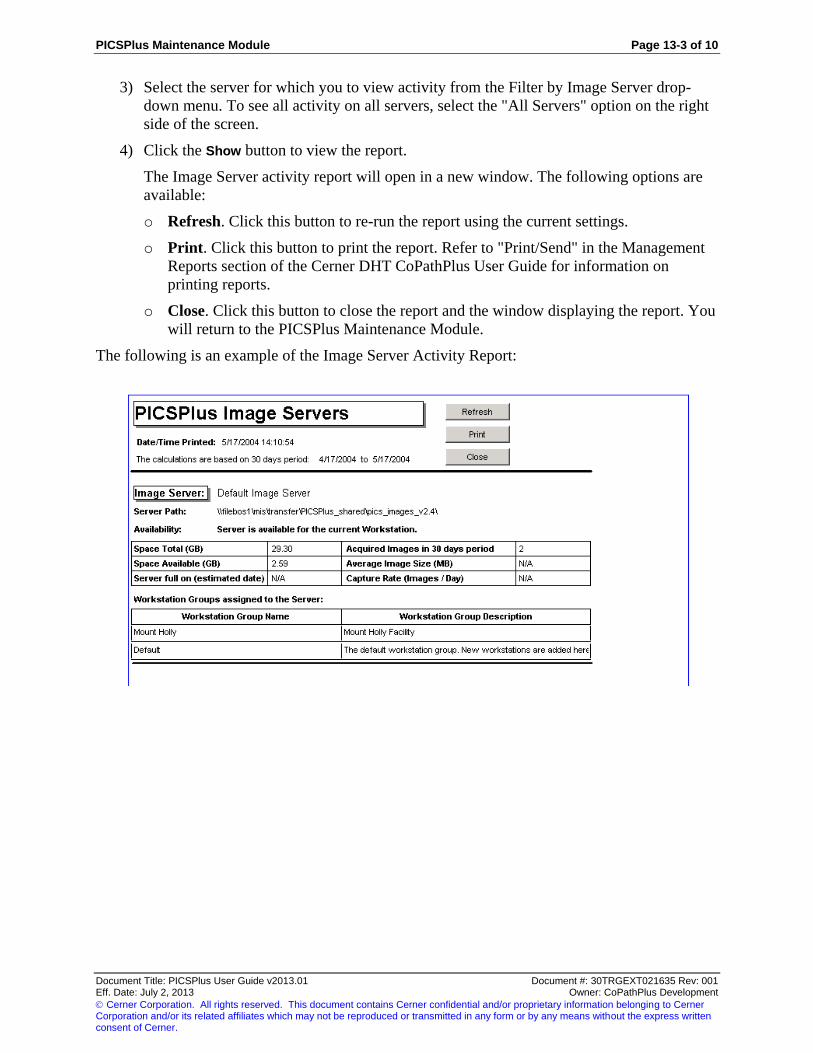
PICSPlus Maintenance Module Page 13-3 of 10
Document Title: PICSPlus User Guide v2013.01 Document #: 30TRGEXT021635 Rev: 001 Eff. Date: July 2, 2013 Owner: CoPathPlus Development
Cerner Corporation. All rights reserved. This document contains Cerner confidential and/or proprietary information belonging to Cerner Corporation and/or its related affiliates which may not be reproduced or transmitted in any form or by any means without the express written consent of Cerner.
3) Select the server for which you to view activity from the Filter by Image Server drop-
down menu. To see all activity on all servers, select the "All Servers" option on the right
side of the screen.
4) Click the Show button to view the report.
The Image Server activity report will open in a new window. The following options are
available:
o Refresh. Click this button to re-run the report using the current settings.
o Print. Click this button to print the report. Refer to "Print/Send" in the Management
Reports section of the Cerner DHT CoPathPlus User Guide for information on
printing reports.
o Close. Click this button to close the report and the window displaying the report. You
will return to the PICSPlus Maintenance Module.
The following is an example of the Image Server Activity Report:

Page 13-4 of 10 PICSPlus Maintenance Module
Document Title: PICSPlus User Guide v2013.01 Document #: 30TRGEXT021635 Rev: 001 Eff. Date: July 2, 2013 Owner: CoPathPlus Development
Cerner Corporation. All rights reserved. This document contains Cerner confidential and/or proprietary information belonging to Cerner Corporation and/or its related affiliates which may not be reproduced or transmitted in any form or by any means without the express written consent of Cerner.
Acquisition Workstation Activity Report
The Acquisition Workstations Activity feature provides an interactive report providing statistical
information on acquisition workstation activity within the last 30 days. This report may be
refreshed without leaving the display. It will provide important information regarding image
distribution when multiple image servers are used to promote load balancing.
Note: The determination to specifically use a 30 day time frame for Image Servers Activity tool was made based on
internal evaluations and experience regarding image capture. If the timeframe is too short, the statistics could easily
be skewed by single days with either lighter than or heavier than normal workflow. Extended periods could render
the tool cumbersome due to potential delays in data retrieval
The report provides the following information:
Number of active Acquisition Workstations
Number of Acquisition licenses
List of active Acquisition Workstations with Workstation Groups
Number of Acquisition Workstations in the each Workstation Group
Number of images acquired by each workstation in 30 days period
The following is an example of the Acquisition Workstation Activity Report window:
To view the Acquisition Workstation Activity Report:
1) Follow the procedures outlined in "Accessing the PICSPlus Maintenance Module" to
open the Maintenance Module.
2) Select Acquisition Workstation Activity from the Mode option buttons displayed on the
left side of the screen.
3) Select the acquisition workstation group for which you to view activity from the Filter by
Workstation Group drop-down menu. To see all activity on all workstations, select the
"All Workstations" option on the right side of the screen.
4) Click the Show button to view the report.

PICSPlus Maintenance Module Page 13-5 of 10
Document Title: PICSPlus User Guide v2013.01 Document #: 30TRGEXT021635 Rev: 001 Eff. Date: July 2, 2013 Owner: CoPathPlus Development
Cerner Corporation. All rights reserved. This document contains Cerner confidential and/or proprietary information belonging to Cerner Corporation and/or its related affiliates which may not be reproduced or transmitted in any form or by any means without the express written consent of Cerner.
The Acquisition Workstation activity report will open in a new window. The following
options are available:
o Refresh. Click this button to re-run the report using the current settings.
o Print. Click this button to print the report. Refer to "Print/Send" in the Management
Reports section of the Cerner DHT CoPathPlus User Guide for information on
printing reports.
o Close. Click this button to close the report and the window displaying the report. You
will return to the PICSPlus Maintenance Module.
The following is an example of the Acquisition Workstation Activity Report:

Page 13-6 of 10 PICSPlus Maintenance Module
Document Title: PICSPlus User Guide v2013.01 Document #: 30TRGEXT021635 Rev: 001 Eff. Date: July 2, 2013 Owner: CoPathPlus Development
Cerner Corporation. All rights reserved. This document contains Cerner confidential and/or proprietary information belonging to Cerner Corporation and/or its related affiliates which may not be reproduced or transmitted in any form or by any means without the express written consent of Cerner.
Detect Lost Images by Specimen Number
The Detect Lost Images by Specimen Number feature is a utility to detect lost images and
thumbnails by specimen number. If PICSPlus cannot identify a specific image, (i.e. it has been
relocated, removed or has become corrupted) this feature will allow you to remove the
association on the specimen previously had to that image. Breaking this link will allow normal
processing to proceed on a specimen.
Note: Deletion is not allowed on incomplete records that belong to a report on signed out specimen.
The Lost Image report displays the Specimen number and status. It also displays the incomplete
image data associated with the specimen. This information includes Capture date; capture
workstation, location, if on report, and name of the physical files.
Note: Before searching for lost images, the system checks the workstation's accessibility to every Active and
Inactive Image Server. If inaccessible servers are detected a message appears warning that the information
displayed could be incomplete. The lost image information displayed is for available Image Servers.
The following is an example of the Detect Lost Images by Specimen Number window:
To detect lost images by specimen number:
1) Follow the procedures outlined in "Accessing the PICSPlus Maintenance Module" to
open the Maintenance Module.
2) Select Detect Lost Images by Specimen Number from the Mode option buttons
displayed on the left side of the screen.
3) Enter the specimen number to which the lost image is associated in the Specimen
Number field. You can also perform a look-up for the specimen by clicking the lookup
button . Refer to "Using the Select Specimen Window" in the Specimens section of
the Cerner DHT CoPathPlus User Guide for more information.
4) Click the Show button to view the report.
The Lost Image Files report will open in a new window.
The following options are available:
o Refresh. Click this button to re-run the report using the current settings.

PICSPlus Maintenance Module Page 13-7 of 10
Document Title: PICSPlus User Guide v2013.01 Document #: 30TRGEXT021635 Rev: 001 Eff. Date: July 2, 2013 Owner: CoPathPlus Development
Cerner Corporation. All rights reserved. This document contains Cerner confidential and/or proprietary information belonging to Cerner Corporation and/or its related affiliates which may not be reproduced or transmitted in any form or by any means without the express written consent of Cerner.
o Print. Click this button to print the report. Refer to "Print/Send" in the Management
Reports section of the Cerner DHT CoPathPlus User Guide for information on
printing reports.
o Close. Click this button to close the report and the window displaying the report. You
will return to the PICSPlus Maintenance Module.
o The following buttons will only display if lost images are detected:
o Select All. Click this button to select all of the lost images for deletion. The Select to
Delete check box for each lost image will be checked when you press this button.
o Clear Selection. Click this button to clear the Select to Delete check box for all lost
images that have been selected.
o The following button will only display if a lost image is selected for deletion:
o Delete Selected. Click this button to clear this image from the database records
associated to this specimen. A warning message will appear before the system deletes
the record.
Warning: Before deleting an image, you should make every effort to restore the image from a backup file
or to manually locate the missing image.
The following is an example of the Detect Lost Images by Specimen Number Report:

Page 13-8 of 10 PICSPlus Maintenance Module
Document Title: PICSPlus User Guide v2013.01 Document #: 30TRGEXT021635 Rev: 001 Eff. Date: July 2, 2013 Owner: CoPathPlus Development
Cerner Corporation. All rights reserved. This document contains Cerner confidential and/or proprietary information belonging to Cerner Corporation and/or its related affiliates which may not be reproduced or transmitted in any form or by any means without the express written consent of Cerner.
Detect Lost Images by Date Range
The Detect Lost Image Files by Date Range utility is used to locate lost images by searching a
specified image capture date range. This option serves the same function as the Detect Lost
Images by Specimen Number feature, but it uses alternate search criteria providing a different
way to locate problematic images. Searching by date range allows the system manager to search
for lost or corrupted images in the event inadequate information regarding potential image-
related problems is received.
This report may be generated for any user stipulated date range. When the Detect Lost Image
Files by Date Range option is selected via the adjacent radio button at the left side of the screen,
the filter available at the right side of the screen becomes a Lost Image Files Date Range filter.
Select the desired date range for report generation.
Note: Deletion is not allowed on incomplete records that belong to a report on signed out specimen.
The Lost Image report displays the Specimen number and status. It also displays the incomplete
image data associated with the specimen. This information includes Capture date; capture
workstation, location, if on report, and name of the physical files.
Note: Before searching for lost images, the system checks the workstation's accessibility to every Active and
Inactive Image Server. If inaccessible servers are detected a message appears warning that the information
displayed could be incomplete. The lost image information displayed is for available Image Servers.
The following is an example of the Detect Lost Images by Date Range window:
To detect lost images by date range:
1) Follow the procedures outlined in "Accessing the PICSPlus Maintenance Module" to
open the Maintenance Module.
2) Select Detect Lost Images by Date Range from the Mode option buttons displayed on
the left side of the screen.
3) Enter the date range in which the lost images were captured. To enter a date range, enter
a From Date (the earliest date you want to search) and the To Date (the latest date you
want to search). You can quickly enter the current date by pressing the Set Today button.

PICSPlus Maintenance Module Page 13-9 of 10
Document Title: PICSPlus User Guide v2013.01 Document #: 30TRGEXT021635 Rev: 001 Eff. Date: July 2, 2013 Owner: CoPathPlus Development
Cerner Corporation. All rights reserved. This document contains Cerner confidential and/or proprietary information belonging to Cerner Corporation and/or its related affiliates which may not be reproduced or transmitted in any form or by any means without the express written consent of Cerner.
If a date range greater than 30 days is selected, the system will provide a warning
regarding potential processing time requirements.
A message will also be display if the "From Date" is later than the "To Date". This type
of date entry error will need to be corrected to proceed.
Date selection conventions include:
o Press the respective Set Today button to refresh to the current day for either the From
Date or the To Date field
o Type in the desired date into either field
o Position your cursor within the month, day, or year portion of either the From Date or
the To Date field. Click the appropriate arrow:
Press the down arrow to the right of the date to move the selected date parameter
(month, day, or year) earlier
Press the up arrow to the right of the date to move the selected date parameter
(month, day, or year) later
For example, if the current date display is set to 08/26/05, position your cursor in the
month portion of the date and press the down arrow to move the date to 07/26/05. Then
position your cursor in the day field of this date and press the up arrow twice to change
the date to 07/28/05.
4) Click the Show button to view the report.
The Lost Image Files report will open in a new window. The following options are
available:
o Refresh. Click this button to re-run the report using the current settings.

Page 13-10 of 10 PICSPlus Maintenance Module
Document Title: PICSPlus User Guide v2013.01 Document #: 30TRGEXT021635 Rev: 001 Eff. Date: July 2, 2013 Owner: CoPathPlus Development
Cerner Corporation. All rights reserved. This document contains Cerner confidential and/or proprietary information belonging to Cerner Corporation and/or its related affiliates which may not be reproduced or transmitted in any form or by any means without the express written consent of Cerner.
o Print. Click this button to print the report. Refer to "Print/Send" in the Management
Reports section of the Cerner DHT CoPathPlus User Guide for information on
printing reports.
o Close. Click this button to close the report and the window displaying the report. You
will return to the PICSPlus Maintenance Module.
o The following buttons will only display if lost images are detected:
o Select All. Click this button to select all of the lost images for deletion. The Select to
Delete check box for each lost image will be checked when you press this button.
o Clear Selection. Click this button to clear the Select to Delete check box for all lost
images that have been selected.
o The following button will only display if a lost image is selected for deletion:
o Delete Selected. Click this button to clear this image from the database records
associated to this specimen. A warning message will appear before the system deletes
the record.
Warning: Before breaking a linking between a specimen and an image, also known as "deleting an image",
you should make every effort to restore the image from a backup file or to manually locate the missing
image.
The following is an example of the Detect Lost Images by Date Range: