Embed Size (px)
Citation preview

PicoCell 2HP Manual
Revision 5


Contents:
Section Page
PicoCell at Glance
Sizing the Solar Pumping system
PicoCell Installation Requirements
PicoCell Description
PicoCell Specification
PicoCell Hardware
PicoCell Mounting Instructions
PicoCell Overview
PicoCell Wiring Instructions
PicoCell Settings
PicoCell Operation
PicoCell Accessories
10 Quick Steps Installation
Installation Notes & Maintenance
Troubleshooting – Indicator Lights
NOTICE
This manual is intended to be used as a quick installation and operation manual The information in this document is subject to change without notice. No part of this document may be reproduced in any form or by
any means without the express written permission of SunTech Drive LLC.
PicoCell PicoPanel SolProtect and Power Blending Controller are trademarks of SunTech Drive LLC
1
2
3
4
5
6
7
8
9
10
12
14
16
17
18


PicoCell at Glance
Page 1
PicoCell is an off-grid solar controller that can operate any alternating current (AC) motor
load up to 1.5 HP single-phase/2HP three-phase from solar photovoltaic (PV) power.
PicoCell has unique functionality that enables users to match AC load with Solar PV
power, in order to make solar water pumping and other solar-powered applications
affordable using commercially and locally available AC pumps.
For sizing the solar PV panels when using a using PicoCell controller, please use the
Configuration Table on page 2 for the selected motor, or consult with your local dealer
or contact SunTech Drive.
A typical diagram for a solar water pumping system that uses a PicoCell controller is
shown in Figure 1. The solar PV array should be connected to the PicoCell controller via
the DC Disconnect, as shown in Figure 1. PicoCell controllers should be installed in the
shade (potentially mounted under PV array) and away from the direct sun.
When connecting the Solar PV or motor/pump wires to the PicoCell controller, ensure
the DC Disconnect is OFF. Ensure that the grounding wires from the DC Disconnect (PV
Array) and the motor/pump are connected to the dedicated grounding lug of the PicoCell
controller. An optional water level switch can be connected to the PicoCell. Inside the
PicoCell there is a dedicated terminal next to the motor terminal block for two water
level switches (tank or well). One water level switch indicates when the tank is full. The
other indicates when the well is empty.
Figure 1: Solar water pumping system diagram
The PicoCell off-grid solar controller is unique because it
is universal and can run single or three phase AC solar
water pumps, 115 or 230V, and 50 or 60Hz. Consult with
your dealer in order to make sure the solar PV array is
properly sized for your application.
AC Water Pump
Water Tank
PicoCell
DC DisconnectPV Solar Array
Level Switch
AC Water Pump
Water Tank
PicoCell
DC DisconnectPV Solar Array
Level Switch

Sizing the Solar Pumping System
Sizing the solar system to power PicoCell and a given motor load (pump, compressor, fan, etc.) is based on the power requirement of the motor load, motor phase, daily duty cycle of the system and installation location.
Three-phase motor loads will typically require less solar PV capacity than single-phase
loads, due to higher electrical efficiency. 3-phase pumps are more cost effective because they require less solar PV power. 1-phase motor loads with running capacitors (also called split-phase), will also require higher solar PV power at startup than 3-phase counterparts. Service Factor (SF) can also vary between motor manufactures. Higher SF may require more PV solar power.
Daily duty cycle dictates how long the motor load has to run when powered, by solar, which directly affects the amount of solar PV required. The longer the run time, the greater the Solar PV capacity is needed, but it is not a linear relationship.
Table 1 below provides recommended solar PV requirement for different 1-phase and 3-phase motor loads, based on the nominal power and current. When sizing the solar PV capacity for using PicoCell, always look at service factor current and power, also called: SF Amps.
Page 2
The table above provides a general rule for sizing the solar PV capacity when using the PicoCell controller. Different motor manufacturers specify their HP ratings differently,
so the table is providing informative value, rather than strict solar PV capacity for a given application. Furthermore, configuring solar PV capacity will vary based on location of the installation (i.e. different solar irradiances at different latitudes).
For more detailed solar PV configuration, please contact the SunTech Drive sales team
or your local dealer. Be ready to provide the motor load s nameplate information, as well as installation site location and application requirements of desired daily duty cycle.
Table 1: Solar PV configurator table for PicoCell
* Higher min Vmpp voltage is for 230Vac rated motor loads

PicoCell Installation Requirements
The PicoCell must be installed in a shaded location, away from any source of heat and moisture, and in an area free of vegetation. Provisions must also be made to protect the unit from damage by unauthorized persons, large animals, overgrowth, flooding, or other harm.
Page 3
WARNING HIGH VOLTAGES
PicoCell unit has voltages capable of causing severe injury or death by electrical shock, and it should only be installed or serviced by a SunTech Drive
authorized supplier or dealer familiar with the PicoCell.
Whenever possible, the unit should be mounted at least 2 feet (60cm) above the ground. A minimum of 10 inches (25cm ) clearance above the PicoCell is required for internal access. There must not be any obstruction to air flow at the heat sink. A typical installation on an array structure is shown below.
• Contact the SunTech Drive Supplier/Dealer for any service or warranty claims
• NEC codes take precedence over suggestions in this manual
• We strongly recommend that the installation data be recorded into Installation
Notes section of this manual (pp 17) and that the manual is stored near the unit
Solar PV panel
Solar PV rack
10"
24"
Solar PV panel
Solar PV rack
10"
24"
PicoCell Description
Page 4
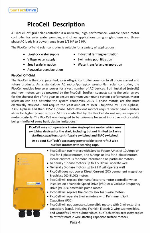
PicoCell may not operate a 2-wire single-phase motor which uses switching devices for the start, including but not limited to 2 wire
starting capacitors, centrifugally switched and BIAC switched.
Ask about SunTech s accessory power cable to retrofit 2 wire surface motors with starting caps.
PicoCell Off-Grid
The PicoCell is the core, patented, solar off-grid controller common to all of our current and future products. As a standalone AC motor/pump/compressor/fan solar controller, the PicoCell enables free solar power for a vast number of AC devices. Both installed (retrofit) and new motors can be powered by the PicoCell. SunTech suggests sizing the solar arrays for the shortest day of the year to ensure optimum year-round system performance. Motor selection can also optimize the system economics. 230V 3-phase motors are the most electrically efficient - and require the least amount of solar - followed by 115V 3-phase, 230V 1-phase and then 115V 1-phase. More efficient motors require fewer panels and/or allow for higher power motors. Motors controlled by the PicoCell do not require separate motor controls. The PicoCell was designed to be universal for most inductive motors while being mindful of some basic design limitations:
• PicoCell can run motors with Service Factor Amps of 10 Amps or less for 1-phase motors, and 8 Amps or less for 3-phase motors. Please contact us for more information on particular motors.
• Generally 1-phase motors up to 1.5 HP will operate well• Generally 3-phase motors up to 2 HP will operate well• PicoCell does not power Direct Current (DC) permanent magnet or
Brushless DC (BLDC) motors• PicoCell will replace the manufacturer s motor controller when
installed on a Variable Speed Drive (VSD) or a Variable Frequency Drive (VFD) submersible pump motor
• PicoCell will replace the control box for 3-wire motors• PicoCell will operate 2-wire motors with Permanent Split
Capacitors (PSC)• PicoCell will not operate submersible motors with 2-wire starting
capacitors (caps), including Franklin Electric 2-wire submersibles, and Grundfos 2-wire submersibles. SunTech offers accessory cables to retrofit most 2 wire starting capacitor surface motors.
A PicoCell off-grid solar controller is a universal, high performance, variable speed motor controller for solar water pumping and other applications using single-phase and three-phase AC loads in a power range from 1/3 HP to 2 HP.
The PicoCell off-grid solar controller is suitable for a variety of applications:
• Industrial farming ventilation
• Swimming pool filtration
• Water transfer and evaporation
• Livestock water supply
• Village water supply
• Small scale irrigation
• Aquaculture and aeration
• Industrial farming ventilation
• Swimming pool filtration
• Water transfer and evaporation
• Livestock water supply
• Village water supply
• Small scale irrigation
• Aquaculture and aeration

Page 5
PicoCell Specification
MPPT operating voltage:
Solar PV open circuit voltage:
Minimum operating PV voltage:
Maximum PV panel current:
Maximum AC motor current:
Single phase AC motor power:
Three phase AC motor power:
100-380V
400V
100V
9A
1.5HP
2HP
Protections:
Overcurrent, overvoltage, short circuit, overload, temperature, open circuit.
ELECTRICAL MECHANICAL
Degree of protection:
Enclosure material:
Operating temperature:
Dimensions:
Solar terminals:
Motor terminals:
Float Sensor terminals:
Cooling:
NEMA4/IP66
Aluminum
-40°C to 50°C
10"x5.5"x4"
AWG#10-14
AWG#10-14
AWG#14-18
Optional:
WiFi and cellular communication modules
Passive/no fan
10A
Input Specification
- Minimum Operating Voltage :
100 Vdc (for 115 Vac, 60 Hz, 1-phase motors)
150 Vdc (for 230/240 Vac, 50/60 Hz, 1/3-phase motors)
- Maximum Open Circuit Voltage : 400Vdc
- Maximum Solar PV Current: 9 Amps
- Earth-ground connected to chassis
Output Specification
- Maximum Output Current: 10Arms (1-phase motors)
- Maximum Output Current: 8Arms (3-phase motors)
- Maximum Power Sustained 2500 W
- Efficiency: 97% (3-phase) and 95% ( 1-phase)
- Selectable Nom. Freq. 50, 60 Hz
- Float switch - shuts off PicoCell
ENVIRONMENTAL: Compliance with IEC 60068
IEC 60068-2-2 - Cold IEC 60068-2-2 – Dry Heat
IEC 60068-2-14 - Change of temperature IEC 60068-2-30 – Damp Heat

Page 6
PicoCell Hardware
A PicoCell controller consists of several components, as shown in Figure 2. The unit has three wire glands: two large glands for motor and solar PV cables, and one smaller gland for data cables (float switch sensor or other optional sensors). There is direct access to the power and signal terminals of the PicoCell once the enclosure door is removed.
The PicoCell controller should be mounted on the wall or other vertical surface using the back bracket (see Figure 2 below). On a back side of the unit, in the upper corners of the heatsink, are two pins used to hang the unit on the back panel. More detailed mounting instructions are shown on page 4.
Figure 2: PicoCell hardware
Heatsink
Enclosure Door for wiring
Pin hole for hanging the PicoCell to the back panel
Back view Front view
Back panel (wall mount)
Wire glands

Mounting PicoCell
3 Make sure both screw pins are used to hang the PicoCell onto the back bracket
Fix the back plate to the support surface through 3 holes using screws (not included)
1 Fix the back plate to the support surface through 3 holes using screws (not included)
1
Page 7
2 Once the back plate is fixed to
the wall, hang the PicoCell onto the back plate using
the screw pins on the heatsink
4 Mounted!

PicoCell Overview
The features of a PicoCell controller are shown in Figure 3. The unit has two wire glands
(right and left, for motor and solar PV power cables), and one wire gland (in the middle, for
the data cables for outside sensors). Further details about wiring the unit are provided on
page 9.
Three LEDs are used to indicate the PicoCell controller's operation. More details about the
unit's operation and how to understand PicoCell's LEDs are provided on pages 13 and 17.
Once the door of the enclosure is open, there are three terminal blocks:
1) solar PV wires
2) motor/pump wires
3) pump or tank sensor wires. More information about signal wiring and how to use the
toggle ON/OFF switch and DIP switches is provided on page 11.
Figure 3: PicoCell features overview
Page 8
Single/Three phase Motor Cables
Solar PV Cables
Sensor data cables
Pump LED
Solar PV LED
Warning LED
DIP SwitchON
1 2 3
ON
1 2 3
120Vac
230Vac
50Hz
60HzThree phase
Single phase
Motor/Pump Terminals
Controller Reset Switch
Pump or Tank Sensor wire Terminals
Solar PV Terminals
Solar PV Grounding Lug
Motor Grounding Lug
ON/OFF Switch
(1)
(2)
(3)
Single/Three phase Motor Cables
Solar PV Cables
Sensor data cables
Pump LED
Solar PV LED
Warning LED
DIP SwitchON
1 2 3
120Vac
230Vac
50Hz
60HzThree phase
Single phase
Motor/Pump Terminals
Controller Reset Switch
Pump or Tank Sensor wire Terminals
Solar PV Terminals
Solar PV Grounding Lug
Motor Grounding Lug
ON/OFF Switch
(1)
(2)
(3)

Page 9
PicoCell Wiring DiagramA typical wiring scenario of the PicoCell controller is shown in Figure 4 below.
1) The AC motor pump wires should be brought inside the PicoCell controller through the
left gland.
2) The PV solar wires should be brought inside through the right gland.
3) The ground wires should be brought inside the PicoCell controller through the right and
left glands from the AC load and PV panels, and connected to the grounding lugs.
Figure 4: PicoCell wiring details
IMPORTANT:
The PicoCell unit should be grounded using separate grounding wires: one for the PV panels, and one for the AC motor or pump, as shown in Figure 4.
Never run the PicoCell controller when the AC pump is not connected! It might cause damage to the controller.
If an installed 3-phase pump does not start pumping water, switch the positions of any two of three motor wires. It will change direction of rotation and start pumping water!
CAUTION: When connecting the wires between the DC Disconnect and the
PicoCell controller, make sure the DC Disconnect is turned OFF. Make sure the
toggle switch of the PicoCell is in the OFF position as well!
IMPORTANT:
Single phase 2-wire motor pumps: Connect to A and C motor terminals of PicoCell
Single phase 3-wire motor pumps: Ph_A: YELLOW wire – common motor lead
Ph_B: RED wire – start motor lead
Ph_C: BLACK wire – main motor lead
PV+PV-
GNDGNDPh_A
Ph_BPh_C
2 G 1
Tank/Well Level Switch
Solar PV Wires
AC Motor Wires
G
(1) (2)(3) (3)
AA BB CC
PV+PV-
GNDGNDPh_A
Ph_BPh_C
2 G 1
Tank/Well Level Switch
Solar PV Wires
AC Motor Wires
G
(1) (2)(3) (3)
A B C
Page 10
PicoCell Settings
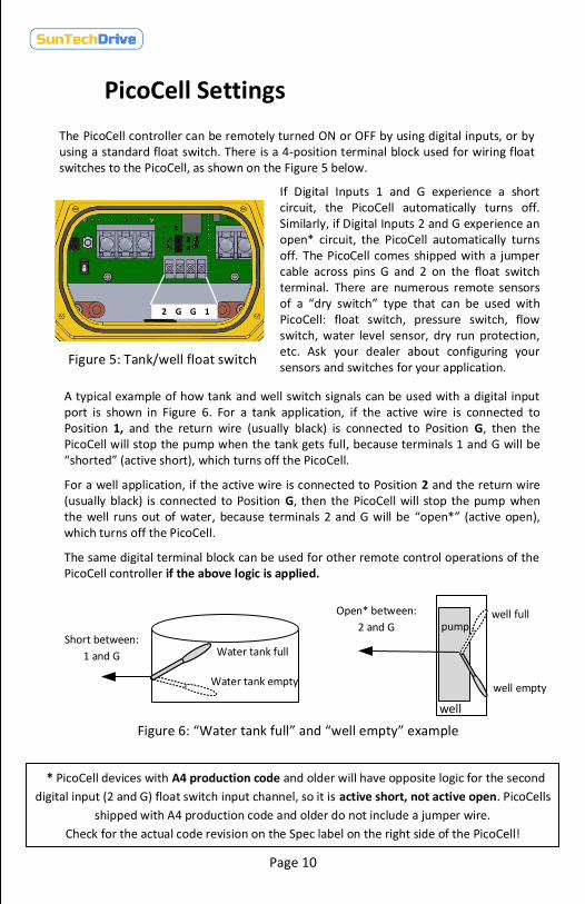
Figure 6: Water tank full and well empty example
Water tank full
Water tank empty
Short between:
1 and G
well full
well empty
pump
well
Open* between:
2 and G
The PicoCell controller can be remotely turned ON or OFF by using digital inputs, or by using a standard float switch. There is a 4-position terminal block used for wiring float switches to the PicoCell, as shown on the Figure 5 below.
If Digital Inputs 1 and G experience a short circuit, the PicoCell automatically turns off. Similarly, if Digital Inputs 2 and G experience an open* circuit, the PicoCell automatically turns off. The PicoCell comes shipped with a jumper cable across pins G and 2 on the float switch terminal. There are numerous remote sensors of a dry switch type that can be used with PicoCell: float switch, pressure switch, flow switch, water level sensor, dry run protection, etc. Ask your dealer about configuring your sensors and switches for your application.
2 G G 1 2 G G 1 2 G G 1
Figure 5: Tank/well float switch
2 G G 1
Figure 5: Tank/well float switch
A typical example of how tank and well switch signals can be used with a digital input port is shown in Figure 6. For a tank application, if the active wire is connected to Position 1, and the return wire (usually black) is connected to Position G, then the PicoCell will stop the pump when the tank gets full, because terminals 1 and G will be shorted (active short), which turns off the PicoCell.
For a well application, if the active wire is connected to Position 2 and the return wire (usually black) is connected to Position G, then the PicoCell will stop the pump when the well runs out of water, because terminals 2 and G will be open* (active open), which turns off the PicoCell.
The same digital terminal block can be used for other remote control operations of the PicoCell controller if the above logic is applied.
* PicoCell devices with A4 production code and older will have opposite logic for the second
digital input (2 and G) float switch input channel, so it is active short, not active open. PicoCells
shipped with A4 production code and older do not include a jumper wire.
Check for the actual code revision on the Spec label on the right side of the PicoCell!

Page 11
The PicoCell controller can operate most AC water pumps: single or three phase; 50 or 60Hz; 120Vac or 230Vac rated. In order for the PicoCell to match the correct pump, DIP switches are used:
DIP Switch
ON
1 2 3
ON
1 2 3
120Vac
230Vac
50Hz
60Hz- DIP switch 1 – if pulled up (ON – as on Figure 9), the unit is configured for 120Vac pump operation; if pulled down (OFF), the unit is configured for 230Vac.
- DIP switch 2 – if pulled up (ON – as in Figure 9), the unit is configured for single phase pump operation; if pulled down (OFF), the unit is configured for three phase operation of pump.
- DIP switch 3 – if pulled up (ON – as on Figure 9), the unit is configured for 50Hz pump; if pulled down (OFF), the unit is configured for 60Hz pump.
The PicoCell controller has a RESET button, positioned on the left side, next to the motor power terminal block, as shown in Figure 7.
The Reset button can be pressed briefly to reboot the software if the PicoCell controller is not performing correctly. The RESET button should be used whenever the dip switch settings are changed (for example, if the pump is changed) and for trouble shooting scenarios.
Single phase
PicoCell Settings
RESETRESETRESET
Figure 7: Reset Button
The PicoCell controller has an internal toggle switch for turning the unit ON and OFF. This switch is not a power switch. It is signal switch (Figure 8). When it is in the OFF position, the PicoCell controller is NOT de-energized from the solar PV array. It is in OFF mode, not running the pump. When the toggle switch is OFF, all three LEDs are ON.
When the toggle switch is in the ON position, the PicoCell controller is in regular RUN mode, controlling the AC water pump and pumping the water. During RUN mode, the green PUMP LED is ON (page 8).
ON
OFF
ON
OFF
ON
OFF
Figure 8: ON/OFF Toggle switch
Figure 9: DIP switches
Three phase

PicoCell Operation
Page 12
Once the PicoCell controller is connected to the solar water pumping system as shown
(Figure 1, page 1), and wired per instructions shown (Figure 5, page 5), and DIP switch
settings are put in the correct position to match the motor specification (Figure 4,
page 9), then the PicoCell controller is ready for operation.
Startup:
If the PicoCell unit is powered, all three LEDs will be
solid ON. Once the toggle switch (Figure 8, page 11)
is turned ON, the PicoCell checks its motor
connections. The PicoCell has built in open and
short circuit protections, so if one of the motor
leads is not connected, or there is a short in the
motor connections, The PicoCell will show a
warning message using indication LEDs (see page
17 for LED Indicators).
Figure 10: LED 1 – AC POWER ON
If the motor is properly connected, the PicoCell will move to it s startup procedure, and
the green AC POWER LED (Figure 10) will start blinking, indicating that the PicoCell
controller is trying to start the pump. If there is enough solar power available, the
pump will start running, at which point the green AC POWER LED will turn solid green.
During start-up mode, the PicoCell controls the motor/pump so that it starts from
standstill to 30Hz of operation in 1 second, and then the Maximum Power Point
Tracking (MPPT) algorithm takes over, optimizing the motor/pump s speed to match
available power from the solar PV source.
The PicoCell has built in overload protection, so it first slows down, and then shuts off
the motor/pump if the overload condition continues. Toward the end of the day, as
solar intensity weakens, the PicoCell will slow down the operation of the motor/pump
until there is not enough solar available, and will shut off the pump if the speed drops
below 30Hz.
Built-in protections:
• open circuit
• short circuit
• over load
• overcurrent
• overvoltage
• over temperature
Built-in protections:
• open circuit
• short circuit
• over load
• overcurrent
• overvoltage
• over temperature

PicoCell Operation
Page 13
If the unit cools down to regular operating temperature it
will continue its normal operation without the thermal
deration.
Otherwise, if the temperature of PicoCell continues to increase, the unit will eventually
cease its operation, at which point the WARNING LED is solid red.
If the PicoCell unit during its normal operation gets too hot,
it will switch to power deration mode, limiting maximum
power transferred to the motor load. During that time, the
AC POWER LED is solid green, while WARNING LED is solid
red (Figure 13).
Figure 12: LED 3 – WARNINGFigure 12: LED 3 – WARNING
Figure 11: LED 2 – Low Solar PVFigure 11: LED 2 – Low Solar PV
Figure 13: Thermal DerationFigure 13: Thermal Deration
Shutdown:
The best way to shutdown the unit is to disconnect the Solar PV array using the external DC
Disconnect.
If there is not enough solar power to start the pump, the
yellow SOLAR LED (Figure 11) will start blinking, indicating
there is not enough solar PV power. The yellow SOLAR LED
will blink for about 30-60 seconds, indicating that the unit is
in idling mode. During this time, there is no activity and the
PicoCell controller is getting ready for another attempt to
start the pump. Low Solar PV can be due to cloudy weather,
or can happen in the early morning or late evening, when
solar PV panels do not generate enough power for running the pump.
However, if a tank or well float switch are used (Figures 6
and 7), then when the tank becomes full or the well
becomes empty, the PicoCell controller will stop its
operation, and the WARNING LED will be blinking red. The
same outcome can be achieved by shorting any one of two
float switches, so it is possible to use any remote switch
(Figure 12). The WARNING LED will also be solid red if the
temperature of the PicoCell gets above 80° C, at which point
the unit will cease its operation, and wait until the temperature drops. This can happen if the
unit is directly exposed to the Sun, which should be avoided.

PicoCell Accessories
Page 14
- Intelligently blends energy input from solar PV and power grid
- Maintains full power 24/7 while minimizing power costs
- Provides Power Factor Correction for AC loads from the AC grid
- Universal compatibility – use single/three phase, 50 or 60Hz, 120Vac or 230Vac
electrical loads powered of off single phase electrical grid
- Operating status conditions indicated by multicolor LEDs
- Phase decoupling – allows for the use of three phase motors on single phase grids
Grid Power Blender - seamlessly blends energy between a solar array and the power grid. It is ideally suited for applications that require 24/7 or some night time operation, particularly in areas with high power costs. The combination of the PicoCell controller and Power Blender represents a very cost effective way to supplement solar power with controllable night time operation without the expense of adding a bank of batteries.
If there is a full solar irradiance, the PicoCell and Power Blender will draw maximum power from the PV array. As cloud cover or impending darkness reduce the level of solar irradiance, the system automatically makes up the difference by drawing from the grid. As full darkness descends the system draws all of its power from the grid. In high energy cost areas this allows for both power firming during the day and full nighttime operation while consuming as little power from the grid as possible.

PicoCell Accessories
Float Switch - Commonly used with the PicoCell as a switch to indicate full tank conditions for water pumping applications. It is wired to the float switch connectors 1G or 2G of PicoCell . The FLOAT SWITCH comes with 10ft of cable.
Page 15
SolSwitch – A transfer box used for switching between solar power or grid power. The SolSwitch is connected to the PicoCell as well as to the AC grid/generator and has a simple and safe panel switch between two modes: solar
or AC power. The unit also has an integrated DC disconnect switch.
The SolSwitch is suitable for single and three phase AC motors and AC grid, 120 and 230Vac, 50 and 60Hz and is rated for 10Aac.
DC Disconnect – A necessary disconnect switch that connects the Solar PV array with an input terminal of the PicoCell. This is 2 Pole (Single String) Enclosed DC Switch IP66 rated, with dimensions: 180x98x107mm. Electrical
specs: 16A 800 VDC.
VFD FILTER – This device is commonly used for installations with cable length longer than 300ft. The VFD FILTER is connected to the output of the PicoCell on one side, and the motor leads on the other. The VFD FILTER is rated for 10Aac current and up to 1000V peak phase voltage.
New for 2018! Contact your local dealer for solutions for single phase 2-wire starting capacitor surface pumps.

PicoCell Installation - 10 Quick Steps
Securely screw the enclosed mounting bracket onto a solid vertical surface. Hang the PicoCell unit on the bracket, using the heatsink screw pins as shown on the picture to the right.
1
With the enclosure door removed, connect the motor or pump connections first. Pass the wire leads through the wiring glands and connect to the left side connectors and left-bottom ground lug. These connectors are clearly labeled A, B and C. The ground lugs are located directly below the circuit board. - Connect phases A and C for a single phase pump - Connect phases A, B and C for a three phase pump
3
5
4
Remove the enclosure door and make sure that the toggle switch is in the OFF position before doing any wiring!
Turn the DC Disconnect OFF, and ensure that there is no voltage on the solar PV wires!
2
Page 16
While the DC disconnect is still OFF, connect the solar PV wires. Pass the PV+ and PV- wires through the right cable gland and connect them to the right side connectors. Also connect the solar ground to the right-bottom grounding lug. The connectors on the board are labeled PV+ and PV-.
1
5
6
7
4
9
3
5
4 7
3 3
3
5
6
7
4
9
3
5
4 7
3 3
3
See Figure 4, Page 9for detailed wiring diagram
Set up the DIP switches to match the phase, voltage and frequency of the motor or pump that the PicoCell is connected to.
6 Set up the DIP switches to match the phase, voltage and frequency of the motor or pump that the PicoCell is connected to.
6
After passing the wires through the middle cable gland, connect the remote tank or well float switch to the terminal block next to the motor connector.
7 After passing the wires through the middle cable gland, connect the remote tank or well float switch to the terminal block next to the motor connector.
7
Once all of the power and signal connections are made, and the pump settings are adjusted on the DIP switch, energize the circuit by switching the DC Disconnect ON!
8 Once all of the power and signal connections are made, and the pump settings are adjusted on the DIP switch, energize the circuit by switching the DC Disconnect ON!
8
Once the PicoCell is powered up, all three LED lights will light up. Flip the toggle switch to the ON position. This will start the pump.
9 Once the PicoCell is powered up, all three LED lights will light up. Flip the toggle switch to the ON position. This will start the pump.
9
Replace the enclosure door using the slotted screws, and tighten them with a screw driver to seal properly.
1010 Replace the enclosure door using the slotted screws, and tighten them with a screw driver to seal properly.
10

Page 17
Installation Notes:Date Installed :
Serial No. (Spec Label):
Installer:
Phone:
Location of Installation :
Pump Manufacturer / Model No :
Motor : HP, Vac, ph, SF Amps
Well Depth : (m/ft)
Pumping Rate Required : (lpd/gpd)
PV panel manufacturer/Model number :
No. of solar PV panels in series :
Maintenance:
The PicoCell unit is designed to operate autonomously, however it is suggested to be inspected every 3 months. If there are any external obstructions that prevent proper cooling of heat sink area, please remove them to make sure nothing blocks the air flow from bottom of the device.
If the PicoCell operates in the area where the pump experiences freezing temperatures, make sure to turn OFF device so it does not try to run the water pump in icy conditions, or it will experience dead heading on the pump!
Check external sensors every 3 months: float switch, pressure switch etc. if used as a part of the PicoCell Solar installation.
We strongly recommend that the installation notes (above) are filled out with valid data and that the manual remain accessible and kept close to the unit. Also, if you are calling our technical support, please have this installation data available for a more accurate and faster troubleshooting process.

Troubleshooting - Indicator Lights
There are three LED indicator lights which indicate various system fault conditions. These lights are visible through light piper on the front cover. A list of these indicator lights and recommended corrective actions are listed below.
Page 18
OFF Mode when PicoCell toggle switch is turned OFFOFF Mode when PicoCell toggle switch is turned OFF
Startup Mode when PicoCell is in process of starting the motor pumpStartup Mode when PicoCell is in process of starting the motor pump
Running Mode when PicoCell is running the motor pumpRunning Mode when PicoCell is running the motor pump
Standby Modewhen there is not enough power from the Solar PV panels
for PicoCell to start motor pumpStandby Mode
when there is not enough power from the Solar PV panels
for PicoCell to start motor pump
Float Switch Mode
when PicoCell is turned OFF as a result of input from one or more external sensors that are connected to the digital
input of PicoCellFloat Switch Mode
when PicoCell is turned OFF as a result of input from one or more external sensors that are connected to the digital
input of PicoCell
Over Temperature ModePicoCell stops operation as a result of an over temperature
event when the temperature inside the unit exceeds 80°COver Temperature Mode
PicoCell stops operation as a result of an over temperature
event when the temperature inside the unit exceeds 80°C
Power Deration Mode
PicoCell still operates but with reduced power throughput due to increased operating temperature. If the temperature of the unit does not decrease, the unit will
stop and go into Over temperature mode.
Power Deration Mode
PicoCell still operates but with reduced power throughput due to increased operating temperature. If the temperature of the unit does not decrease, the unit will
stop and go into Over temperature mode.
Short Circuit/Over-Current
Mode
PicoCell stops operation as a result of detected high current on motor terminals. This can also be due to the
short circuit event if the unit is mis-wired.
Short Circuit/Over-Current
Mode
PicoCell stops operation as a result of detected high current on motor terminals. This can also be due to the
short circuit event if the unit is mis-wired.
Open Circuit ModePicoCell can not start operation if the motor wiring does
not align with DIP switch selection.Open Circuit Mode
PicoCell can not start operation if the motor wiring does
not align with DIP switch selection.
Green LED Orange LED Red LED
ON ON ON - OFF modeON ON ON - OFF mode
FLASHING OFF OFF - Startup modeFLASHING OFF OFF - Startup mode
ON OFF OFF - Running modeON OFF OFF - Running mode
OFF FLASHING OFF - Standby modeOFF FLASHING OFF - Standby mode
OFF OFF FLASHING - Float switch mode OFF OFF FLASHING - Float switch mode
OFF OFF ON - Over temperature modeOFF OFF ON - Over temperature mode
ON OFF ON - Power deration modeON OFF ON - Power deration mode
FLASHING OFF FLASHING - High current modeFLASHING OFF FLASHING - High current mode
OFF FLASHING FLASHING - Open circuit modeOFF FLASHING FLASHING - Open circuit mode
Green LED Orange LED Red LED
ON ON ON - OFF mode
FLASHING OFF OFF - Startup mode
ON OFF OFF - Running mode
OFF FLASHING OFF - Standby mode
OFF OFF FLASHING - Float switch mode
OFF OFF ON - Over temperature mode
ON OFF ON - Power deration mode
FLASHING OFF FLASHING - High current mode
OFF FLASHING FLASHING - Open circuit mode


Pat. Pending: US Patent Application No.: 62/240,979
Contact:[email protected]
SunTechDrive.com
For further information – scan this code: