Embed Size (px)
Citation preview
© 2009 Microchip Technology Inc. DS51806A
PIC18F46J50 Full-Speed USBDemonstration Board
User’s Guide
Note the following details of the code protection feature on Microchip devices:• Microchip products meet the specification contained in their particular Microchip Data Sheet.
• Microchip believes that its family of products is one of the most secure families of its kind on the market today, when used in the intended manner and under normal conditions.
• There are dishonest and possibly illegal methods used to breach the code protection feature. All of these methods, to our knowledge, require using the Microchip products in a manner outside the operating specifications contained in Microchip’s Data Sheets. Most likely, the person doing so is engaged in theft of intellectual property.
• Microchip is willing to work with the customer who is concerned about the integrity of their code.
• Neither Microchip nor any other semiconductor manufacturer can guarantee the security of their code. Code protection does not mean that we are guaranteeing the product as “unbreakable.”
Code protection is constantly evolving. We at Microchip are committed to continuously improving the code protection features of ourproducts. Attempts to break Microchip’s code protection feature may be a violation of the Digital Millennium Copyright Act. If such actsallow unauthorized access to your software or other copyrighted work, you may have a right to sue for relief under that Act.
Information contained in this publication regarding deviceapplications and the like is provided only for your convenienceand may be superseded by updates. It is your responsibility toensure that your application meets with your specifications.MICROCHIP MAKES NO REPRESENTATIONS ORWARRANTIES OF ANY KIND WHETHER EXPRESS ORIMPLIED, WRITTEN OR ORAL, STATUTORY OROTHERWISE, RELATED TO THE INFORMATION,INCLUDING BUT NOT LIMITED TO ITS CONDITION,QUALITY, PERFORMANCE, MERCHANTABILITY ORFITNESS FOR PURPOSE. Microchip disclaims all liabilityarising from this information and its use. Use of Microchipdevices in life support and/or safety applications is entirely atthe buyer’s risk, and the buyer agrees to defend, indemnify andhold harmless Microchip from any and all damages, claims,suits, or expenses resulting from such use. No licenses areconveyed, implicitly or otherwise, under any Microchipintellectual property rights.
DS51806A-page ii
Trademarks
The Microchip name and logo, the Microchip logo, Accuron, dsPIC, KEELOQ, KEELOQ logo, MPLAB, PIC, PICmicro, PICSTART, rfPIC, SmartShunt and UNI/O are registered trademarks of Microchip Technology Incorporated in the U.S.A. and other countries.
FilterLab, Linear Active Thermistor, MXDEV, MXLAB, SEEVAL, SmartSensor and The Embedded Control Solutions Company are registered trademarks of Microchip Technology Incorporated in the U.S.A.
Analog-for-the-Digital Age, Application Maestro, CodeGuard, dsPICDEM, dsPICDEM.net, dsPICworks, dsSPEAK, ECAN, ECONOMONITOR, FanSense, In-Circuit Serial Programming, ICSP, ICEPIC, Mindi, MiWi, MPASM, MPLAB Certified logo, MPLIB, MPLINK, mTouch, nanoWatt XLP, PICkit, PICDEM, PICDEM.net, PICtail, PIC32 logo, PowerCal, PowerInfo, PowerMate, PowerTool, REAL ICE, rfLAB, Select Mode, Total Endurance, TSHARC, WiperLock and ZENA are trademarks of Microchip Technology Incorporated in the U.S.A. and other countries.
SQTP is a service mark of Microchip Technology Incorporated in the U.S.A.
All other trademarks mentioned herein are property of their respective companies.
© 2009, Microchip Technology Incorporated, Printed in the U.S.A., All Rights Reserved.
Printed on recycled paper.
© 2009 Microchip Technology Inc.
Microchip received ISO/TS-16949:2002 certification for its worldwide headquarters, design and wafer fabrication facilities in Chandler and Tempe, Arizona; Gresham, Oregon and design centers in California and India. The Company’s quality system processes and procedures are for its PIC® MCUs and dsPIC® DSCs, KEELOQ® code hopping devices, Serial EEPROMs, microperipherals, nonvolatile memory and analog products. In addition, Microchip’s quality system for the design and manufacture of development systems is ISO 9001:2000 certified.
PIC18F46J50 FULL-SPEED USBDEMONSTRATION BOARD
USER’S GUIDE
Table of Contents
Preface ........................................................................................................................... 1Chapter 1. Introduction
1.1 Introduction ..................................................................................................... 71.2 Demonstration Board Package Contents ....................................................... 71.3 PIC18F46J50 Family USB Capabilities .......................................................... 7
Chapter 2. Board Hardware2.1 Power Management ..................................................................................... 102.2 LEDs ............................................................................................................. 112.3 Push Buttons ................................................................................................ 112.4 Jumpers ........................................................................................................ 112.5 Programming the Microcontroller ................................................................. 122.6 Operation with the PIC18 Explorer or PICDEM™ HPC Explorer Boards ..... 13
Chapter 3. Preprogrammed Firmware3.1 Overview ...................................................................................................... 153.2 Using the Composite HID+MSD Class Demo Firmware .............................. 173.3 Using the HID Bootloader Firmware ............................................................. 18
Appendix A. Troubleshooting Tips ........................................................................... 21Appendix B. Board Schematics ................................................................................. 23Worldwide Sales and Service .................................................................................... 28
© 2009 Microchip Technology Inc. DS51806A-page iii

PIC18F46J50 Full-Speed USB Demonstration Board User’s Guide
NOTES:
DS51806A-page iv © 2009 Microchip Technology Inc.
PIC18F46J50 FULL-SPEED USBDEMONSTRATION BOARD
USER’S GUIDE
Preface
INTRODUCTIONThis chapter contains general information that will be useful to know before using the PIC18F46J50 Full-Speed USB Demonstration Board. Items in this chapter include:• Document Layout• Conventions Used in this Guide• Warranty Registration• Recommended Reading• The Microchip Web Site• Development Systems Customer Change Notification Service• Customer Support• Document Revision History
DOCUMENT LAYOUTThis document describes how to use the PIC18F46J50 Full-Speed USB Demonstration Board as a development tool to emulate and debug firmware on a target board. The manual layout is as follows:• Chapter 1. “Introduction” – The board package’s contents and the USB
capabilities of the PIC18F46J50 family of devices• Chapter 2. “Board Hardware” – The board’s hardware elements and additional
capabilities available by connecting the board to a PIC18 Explorer Board or PICDEM™ HPC Explorer Board
• Chapter 3. “Preprogrammed Firmware” – The board’s preloaded demonstra-tions, and other demonstrations and projects available in the MCHPFSUSB Framework
• Appendix A. “Troubleshooting Tips” – Solutions for common issues• Appendix B. “Board Schematics” – Schematic diagrams
NOTICE TO CUSTOMERS
All documentation becomes dated and this manual is no exception. Microchip tools and documentation are constantly evolving to meet customer needs, so some actual dialogs and/or tool descriptions may differ from those in this document. Please refer to our web site (www.microchip.com) to obtain the latest documentation available.
Documents are identified with a “DS” number. This number is located on the bottom of each page, in front of the page number. The numbering convention for the DS number is “DSXXXXXA”, where “XXXXX” is the document number and “A” is the revision level of the document.
For the most up-to-date information on development tools, see the MPLAB® IDE online help. Select the Help menu and then Topics to open a list of available online help files.
© 2009 Microchip Technology Inc. DS51806A-page 1
Preface
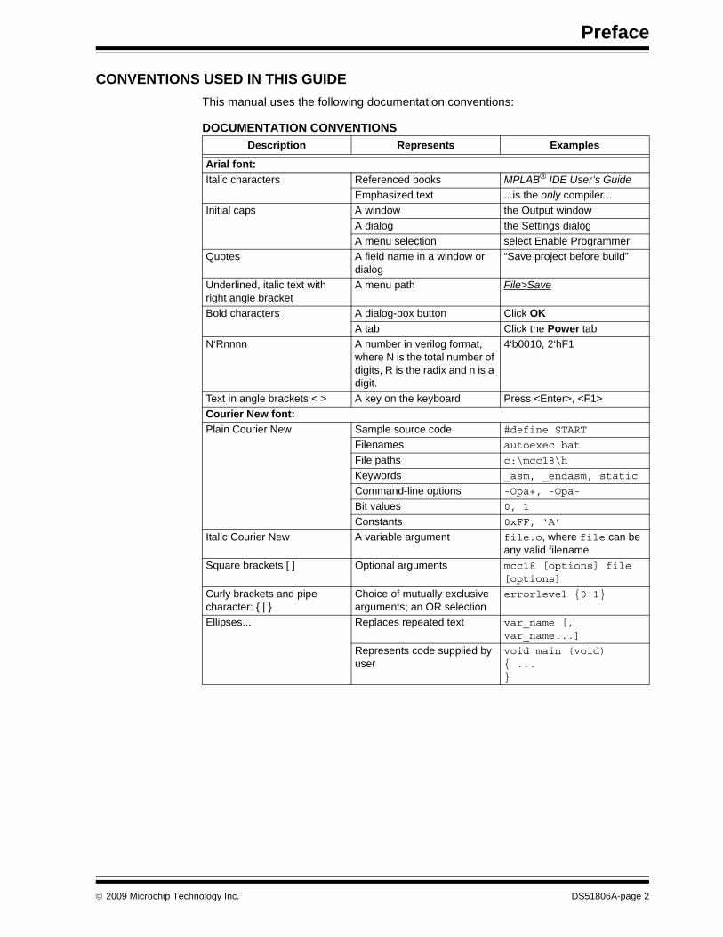
CONVENTIONS USED IN THIS GUIDEThis manual uses the following documentation conventions:
DOCUMENTATION CONVENTIONSDescription Represents Examples
Arial font:Italic characters Referenced books MPLAB® IDE User’s Guide
Emphasized text ...is the only compiler...Initial caps A window the Output window
A dialog the Settings dialogA menu selection select Enable Programmer
Quotes A field name in a window or dialog
“Save project before build”
Underlined, italic text with right angle bracket
A menu path File>Save
Bold characters A dialog-box button Click OKA tab Click the Power tab
N‘Rnnnn A number in verilog format, where N is the total number of digits, R is the radix and n is a digit.
4‘b0010, 2‘hF1
Text in angle brackets < > A key on the keyboard Press <Enter>, <F1>Courier New font:Plain Courier New Sample source code #define START
Filenames autoexec.bat
File paths c:\mcc18\h
Keywords _asm, _endasm, static
Command-line options -Opa+, -Opa-
Bit values 0, 1
Constants 0xFF, ‘A’
Italic Courier New A variable argument file.o, where file can be any valid filename
Square brackets [ ] Optional arguments mcc18 [options] file [options]
Curly brackets and pipe character: { | }
Choice of mutually exclusive arguments; an OR selection
errorlevel {0|1}
Ellipses... Replaces repeated text var_name [, var_name...]
Represents code supplied by user
void main (void){ ...}
© 2009 Microchip Technology Inc. DS51806A-page 2
PIC18F46J50 Full-Speed USB Demonstration Board User’s GuidePIC18F46J50 Full-Speed USB Demonstration Board User’s Guide
WARRANTY REGISTRATIONPlease complete the enclosed Warranty Registration Card and mail it promptly. Sending in the Warranty Registration Card entitles users to receive new product updates.Interim software releases are available at the Microchip web site.
RECOMMENDED READINGThis user’s guide describes how to use the PIC18F46J50 Full-Speed USB Demonstra-tion Board. The following Microchip documents are recommended as supplemental references:• “PIC18F46J50 Family Data Sheet” (DS39931)• MCHPFSUSB Framework’s release notes and other documentationMicrochip provides a variety of USB related application notes, firmware, drivers, PC application source code and other resources to assist application developers. Many of the USB related firmware files, and PC application source code projects and documen-tation are in the earlier referenced MCHPFSUSB Framework on the CD-ROM disc that comes with the board. The latest version of this package and the other resources can be downloaded at the Microchip USB design center:
http://www.microchip.com/usb/
Schematics and other support materials for the PIC18 Explorer Demonstration Board can be obtained at:
http://www.microchip.com/pic18explorer
Schematics and other support materials for the HPC Explorer Demonstration Board can be obtained at:
http://www.microchip.com/HPCExplorer
The official USB 2.0 specifications also could be helpful. These materials can be obtained from the USB Implementer’s Forum:
http://www.usb.org
Chapters 5, 8 and 9 of the USB 2.0 specifications are particularly important for applica-tion developers making USB peripheral devices. These chapters discuss important USB protocol fundamentals and the necessary device requests that must be supported to enable successful USB enumeration.If considering use of the PIC18F46J50 Full-Speed USB Demonstration Board with one of the boards discussed in Chapter 2. “Board Hardware”, the following Microchip documents are recommended:• PICDEM™ PIC18 Explorer Demonstration Board User’s Guide (DS51721)• PICDEM™ HPC Explorer Board Info Sheet (DS51540)
DS51806A-page 3 © 2009 Microchip Technology Inc.
Preface
THE MICROCHIP WEB SITEMicrochip provides online support via the web site at www.microchip.com. The site makes files and information easily available to customers, including the following:• Product Support – Data sheets and errata, application notes, sample programs,
design resources, user’s guides, hardware support documents, and the latest software releases and archived software
• General Technical Support – Frequently Asked Questions (FAQs), links for tech-nical support requests and online discussion groups, and a listing of the Microchip consultant program’s members
• Business of Microchip – Product selector and ordering guides, the latest Microchip press releases, and listings of seminars, events, and Microchip sales offices, distributors and factory representatives
DEVELOPMENT SYSTEMS CUSTOMER CHANGE NOTIFICATION SERVICEMicrochip’s customer notification service helps keep customers current on Microchip products. Subscribers receive email notification whenever there are changes, updates, revisions or errata related to a specified product family or development tool.To register, access the Microchip web site at www.microchip.com, click on Customer Change Notification and follow the registration instructions.The Development Systems product group categories are:• Compilers – The latest information on Microchip C compilers and other language
tools.The tools include the MPLAB® C18 and MPLAB C30 C compilers, MPASM™ and MPLAB ASM30 assemblers, MPLINK™ and MPLAB LINK30 object linkers, and MPLIB™ and MPLAB LIB30 object libraries.
• Emulators – The latest information on Microchip in-circuit emulators.Among the emulators are the REAL ICE™ 2000 and REAL ICE 4000.
• In-Circuit Debuggers – The latest information on the Microchip in-circuit debuggers: PICkit™ 2, MPLAB ICD 2, MPLAB ICD 3 and REAL ICE.
• MPLAB® IDE – The latest information on Microchip MPLAB IDE, the Windows® Integrated Development Environment for development systems tools.This list is focused on the MPLAB IDE, MPLAB SIM simulator, MPLAB IDE project manager, and general editing and debugging features.
• Programmers – The latest information on Microchip programmers.The programmers include the MPLAB PM3 and PRO MATE II device programmers and the PICSTART® Plus and PICkit™ 1 development programmers.
© 2009 Microchip Technology Inc. DS51806A-page 4
PIC18F46J50 Full-Speed USB Demonstration Board User’s GuidePIC18F46J50 Full-Speed USB Demonstration Board User’s Guide
CUSTOMER SUPPORTAssistance for Microchip customers is available through:• Distributors or representatives• Local sales offices• Field Application Engineers (FAEs)• Technical support resourcesCustomers should contact their distributor, representative or Field Application Engineer (FAE) for support. Local sales offices are also available to help customers. A list of sales and service offices is on the back of this document.Technical support is available through the web site at: http://support.microchip.com
DOCUMENT REVISION HISTORY
Revision A (March 2009)• Initial release of this document.
DS51806A-page 5 © 2009 Microchip Technology Inc.

Preface
NOTES:
© 2009 Microchip Technology Inc. DS51806A-page 6
PIC18F46J50 FULL-SPEED USBDEMONSTRATION BOARD
USER’S GUIDE
Chapter 1. Introduction
1.1 INTRODUCTIONThe PIC18F46J50 Full-Speed USB Demonstration Board is designed as an easy-to-use evaluation platform for Microchip’s full-speed, USB PIC18F46J50 family of microcontrollers.The board can be operated as a stand-alone device. Alternately, for additional demonstration functionality, the board can be used in conjunction with the PIC18 Explorer Board (www.microchipDIRECT.com) or PICDEM™ HPC Explorer Board (www.microchipDIRECT.com).All members of the PIC18F46J50 family of microcontrollers fully support USB 2.0 full-speed and low-speed serial communications at signaling speeds of 12 Mbps or 1.5 Mbps.The demonstration board package provides all of the hardware and software needed to develop USB compliant communication solutions.This chapter discusses:• Demonstration Board Package Contents• PIC18F46J50 Family USB Capabilities
1.2 DEMONSTRATION BOARD PACKAGE CONTENTSThe demonstration board package contains:• The PIC18F46J50 Full-Speed USB Demonstration Board, preprogrammed with
composite USB Human Interface Device (HID) and Mass Storage Device (MSD) class demonstration firmware
• A standard USB A to mini-B cable for power and communication• A six-pin, in-line ICSP™ to RJ-11 programming adapter board• The PICDEM™ Starter Kit CD-ROM, containing USB firmware projects, PC appli-
cation source code, USB drivers and USB specific documentation, such as this user’s guide
1.3 PIC18F46J50 FAMILY USB CAPABILITIESThe PIC18F46J50 microcontroller is the “superset” device of the PIC18F46J50 family. The PIC18F46J50 has the largest memory and highest pin count in the family, but otherwise shares a nearly identical feature set with the other family devices. The only exclusionary exceptions are features that require pins not present on the family’s 28-pin devices.
© 2009 Microchip Technology Inc. DS51806A-page 7
All of the devices in the family are code compatible with each other and share these USB capabilities:• USB 2.0 compliance• Full-speed (12 Mbps) and low-speed (1.5 Mbps) operation• Support of control, interrupt, bulk and isochronous transfers• Support of up to 32 endpoints• 3.8 Kbytes of dual access RAM for USB or general purpose use• On-chip features for single chip USB implementation, including:
- USB Serial Interface Engine (SIE)- USB transceiver- USB pull-up resistors- D+ and D- driver output impedance matching resistors
© 2009 Microchip Technology Inc. DS51806A-page 8
PIC18F46J50 FULL-SPEED USBDEMONSTRATION BOARD
USER’S GUIDE
Chapter 2. Board Hardware
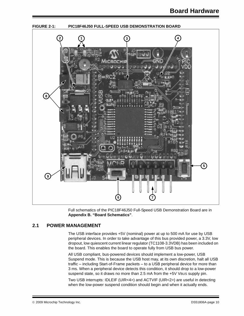
The PIC18F46J50 Full-Speed USB Demonstration Board can be used as a stand-alone device or — for additional functionality — plugged into either the PIC18 Explorer Board (www.microchipDIRECT.com) or PICDEM HPC Explorer Board (www.microchipDIRECT.com).When used alone, the board contains all of the hardware necessary to make a USB compliant, full-speed peripheral device. The board also has additional hardware elements for providing basic demonstration and development capability.The additional elements include the following, with the element’s number indicating its location on the board in Figure 2-1:1. Two miniature SMT red LEDs – Connected to the RE0 and RE1 I/O pins2. 5V to 3.3V LDO low quiescent current regulator (TC1108-3.3VDB) – Enables
device to obtain power from USB port3. 12 MHz SMT crystal – Can be used with the internal PLL to run the
microcontroller and USB module at frequencies of up to 48 MHz 4. MCP9701A analog output temperature sensor – Component U1, connected to
RE2 I/O pin5. General purpose push button S2 – Connected to the RB2 I/O pin with a pull-up
resistor6. MCLR push button – For easy Reset of the microcontroller7. Six-pin, right-angle In-Circuit Serial Programming™ (ICSP™)
programmer/debug header8. Jumpers for current measurement (JP3) and configuration (JP2)9. A mini-B USB connector for power and communication
© 2009 Microchip Technology Inc. DS51806A-page 9
Board Hardware
FIGURE 2-1: PIC18F46J50 FULL-SPEED USB DEMONSTRATION BOARD
Full schematics of the PIC18F46J50 Full-Speed USB Demonstration Board are in Appendix B. “Board Schematics”.
2.1 POWER MANAGEMENTThe USB interface provides +5V (nominal) power at up to 500 mA for use by USB peripheral devices. In order to take advantage of this bus provided power, a 3.3V, low dropout, low quiescent current linear regulator (TC1108-3.3VDB) has been included on the board. This enables the board to operate fully from USB bus power.All USB compliant, bus-powered devices should implement a low-power, USB Suspend mode. This is because the USB host may, at its own discretion, halt all USB traffic – including Start-of-Frame packets – to a USB peripheral device for more than 3 ms. When a peripheral device detects this condition, it should drop to a low-power suspend state, so it draws no more than 2.5 mA from the +5V VBUS supply pin.Two USB interrupts: IDLEIF (UIR<4>) and ACTVIF (UIR<2>) are useful in detecting when the low-power suspend condition should begin and when it actually ends.
12 3 4
5
6 7
8
9
© 2009 Microchip Technology Inc. DS51806A-page 10
PIC18F46J50 Full-Speed USB Demonstration Board User’s Guide
In order to meet this USB suspend current requirement, a USB peripheral should be designed so that it does not place large quiescent loads directly on the +5V VBUS supply line from the USB port. If large loads will be supplied from the USB port, it is suggested that they be connected in a way that they can be turned off when the USB port is placed in the low-power suspend state.The PIC18F46J50 Full-Speed USB Demonstration Board has been designed with these and other power management considerations in mind.
2.2 LEDsTwo high-efficiency, red LEDs have been included on the PIC18F46J50 Full-Speed USB Demonstration Board. The LEDs are connected to I/O pins, RE0 and RE1, and can be used for general purpose indication. The LEDs are connected so that they illuminate when the I/O pin controlling them is driven high.
2.3 PUSH BUTTONSThe board has two miniature push buttons. Push button, S4, connects to Master Clear Reset (MCLR) which resets the microcontroller.Push button, S2, provides a simple user interface for interacting with demonstration firmware projects. Default factory firmware is installed on the board and other USB firmware projects are available in the MCHPFSUSB Framework. (See Section 3.1 “Overview”.)The push button is connected to pin RB2 on the PIC18F46J50 microcontroller which is pulled up to VDD through a 15-kΩ resistor. Pressing the button pulls the RB2 line to ground.
2.4 JUMPERS
2.4.1 JP2 JumperJP2 is a three-pin header with the labels, “I”, “R” and “U”.• “I” – Abbreviation referring to the ICE female header pin for the RC2 signal• “R” – Abbreviation referring to microcontroller pin, RC2• “U” – Abbreviation for the USB_ATTACH signal (see the schematics in
Appendix B. “Board Schematics”.)When the jumper is in the “R” to “I” position, the RC2 pin connects only to the ICE female header pin, just like most of the other general purpose I/O pins. When the jumper is in the “R” to “U” position, RC2 can be used to sense when the USB cable has been attached to the host and when the host is actively providing power to the +5V VBUS line.According to the USB 2.0 specifications, no device should ever pull the D+ or D- lines high (such as with the D+ or D- pull-up resistor) until the host actively powers the +5V VBUS line. This is intended to prevent self-powered peripherals from ever sourcing even small amounts of power to the host when the host is not powered. Small amounts of current could potentially prevent the host (and possibly other USB peripherals connected to that host) from fully becoming depowered, which could cause problems during power-up and initialization.Self-powered peripherals should periodically monitor the +5V VBUS line and detect when it is driven high. Only when it is powered should user firmware enable the USB module and turn on the D+ (for full speed) or D- (for low speed) pull-up resistor, signaling the device attach to the host.
DS51806A-page 11 © 2009 Microchip Technology Inc.
Board Hardware
The JP2 jumper allows the microcontroller firmware to monitor the USB_ATTACH signal when the jumper cap is in the position, R - U.The resistors, R15 and R17 of the schematics (see Appendix B. “Board Schematics”), serve multiple purposes. They level shift the +5V signal, provide a weak pull-down function on the VBUS line (to oppose any leakage that would interfere with measuring VBUS in the off/low state) and improve the ESD robustness of the circuit.Peripherals that are purely bus-powered obtain all of their power directly from the +5V VBUS line itself. For these types of devices, it is unnecessary to monitor when the VBUS is powered as the peripheral will not be able to source current on the D+, D- or VBUS lines when the host is not powered.
2.4.2 JP3 JumperIf the PIC18F46J50 Full-Speed USB Demonstration Board is used as a stand-alone device, it obtains its power from the USB cable. This requires jumper cap, JP3, to be installed, since the jumper is in series with the power supply from the +5V VBUS pin from the USB connector.If the jumper cap is removed from JP3, a current meter can be connected across the header to measure the current consumption from the USB cable. This enables measurement of the total USB +5V VBUS current consumption, which is useful in developing USB devices to meet USB compliance specifications.The current consumption measured at the JP3 header will include the quiescent cur-rent of the linear regulator, Q1, temperature sensor, U1, and the microcontroller, as well as any leakage due to other circuitry on the board.
2.5 PROGRAMMING THE MICROCONTROLLERThe PIC18F46J50 Full-Speed USB Demonstration Board is too small to have the full-sized RJ-11 jack normally used to connect to Microchip In-Circuit Serial Program-ming™ (ICSP™) programmers. Instead, the board has a six-pin ICSP header (J4) that can be used as the connection for reprogramming the microcontroller.The PICkit™ 2 ICSP programmer can be connected directly to the J4 header. Alternately, the six-pin, ICSP to RJ-11 adapter board, included with the board, can be used to reprogram the microcontroller with other RJ-11 based programmers. Examples of ICSP programmers that are supported (at the time this document’s publication) include the MPLAB® In-Circuit Debugger, ICD 2 and ICD 3, and the In-Circuit Emulator, REAL ICE™.When connecting to the six-pin header, ensure that the polarity and alignment are correct. For reference, the board’s silk screen denotes pin 1 of the header (MCLR) with an arrow and has a square surrounding the pin.The RJ-11 to ICSP adapter board also provides a reference on its silk screen with a square around the MCLR pin. When the adapter board connects correctly to the demonstration board, the two square markings are aligned with each other.If the PIC18F46J50 Full-Speed USB Demonstration Board is being used with the PIC18 Explorer Board or PICDEM HPC Explorer Board, the board’s RJ-11 jack can also be used to reprogram or debug the PIC18F46J50.
© 2009 Microchip Technology Inc. DS51806A-page 12
PIC18F46J50 Full-Speed USB Demonstration Board User’s Guide
2.6 OPERATION WITH THE PIC18 EXPLORER OR PICDEM™ HPC EXPLORER BOARDS
The basic hardware capabilities of the PIC18F46J50 Full-Speed USB Demonstration Board can be supplemented by plugging it into the PIC18 Explorer Board or PICDEM HPC Explorer Board. These boards have additional hardware features, such as:• A UART level translator• An RS-232 connector• Eight general purpose indicator LEDs• A potentiometer – Facilitates some of the USB demonstrations that read the
voltage output by the potentiator• A full-size RJ-11-style programming/debugging jack• A PICtail™ daughter board connector – Enables easy probing of I/O pins or
connection to other expansion boards (such as the SD/MMC PICtail™ daughter board, www.microchipDIRECT.com)
Before connecting the PIC18F46J50 Full-Speed USB Demonstration Board to the PICDEM HPC Explorer Board or the PIC18 Explorer Board, ensure that the board’s PIC/ICE slider switch is in the “ICE” position. If the explorer board’s switch is in the wrong position, pin P5 on the PIC18F46J50 Full-Speed USB Demonstration Board is designed to physically interfere with the switch.When the explorer board’s slider switch is in the ICE position, the MCLR pin of the board’s PIC18F8722 microcontroller is held in Reset. This prevents I/O pin contention, even though the PIC18F8722 and PIC18F46J50 microcontrollers electrically share I/O pins when the two boards are connected.
DS51806A-page 13 © 2009 Microchip Technology Inc.

Board Hardware
NOTES:
© 2009 Microchip Technology Inc. DS51806A-page 14
PIC18F46J50 FULL-SPEED USBDEMONSTRATION BOARD
USER’S GUIDE
Chapter 3. Preprogrammed Firmware
3.1 OVERVIEWMicrochip provides a wide variety of USB related example firmware projects, PC application projects, drivers, and other related resources for developing complete USB peripheral and host devices. These resources are included in the MCHPFSUSB Framework distribution package.The free package is on the CD-ROM disc that comes with the board. It can also be downloaded from the Microchip USB Design Center:
http://www.microchip.com/usb
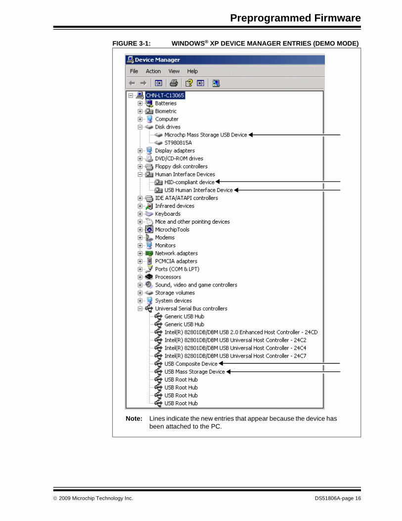
Many of the USB device demonstrations and projects in the MCHPFSUSB Framework are specifically intended for the PIC18F46J50 Full-Speed USB Demonstration Board, so they require no hardware or other modifications.Some example USB firmware is preprogrammed on the PIC18F46J50 Full-Speed USB Demonstration Board. The microcontroller contains both demo firmware and a USB bootloader that is independent of the demo firmware. The bootloader can be used to program a new application’s firmware *.hex files into the microcontroller’s Flash memory, eliminating the need for a dedicated In-Circuit Serial Programming™ (ICSP™) programmer.To enter the Bootloader mode, hold down the S2 push button and momentarily press and release the MCLR push button. The microcontroller firmware checks the RB2 I/O pin state once after coming out of Reset. (For more information on the USB bootloader, see Section 3.3 “Using the HID Bootloader Firmware”.)The microcontroller firmware will enter the demo mode if the RB2 push button is not pressed during power-up or Reset. If the microcontroller is not in the Bootloader mode, it is in Demo mode. (For more information on the composite HID+MSD demo firmware, see Section 3.2 “Using the Composite HID+MSD Class Demo Firmware”.)When a Demo mode device is plugged into a host PC, the device should automatically enumerate as a USB “composite” HID (Human Interface Device) and MSD (mass storage device). Common operating systems (including Windows®, Mac OS® and Linux) ship with built-in HID and MSD class USB drivers. Additional drivers should not be needed to use the default demo firmware programmed on the PIC18F46J50 microcontroller.With successful enumeration in Demo mode, under the Windows operating system, additional entries should appear in the Windows Device Manager dialog box. Figure 3-1 shows how the dialog box appears in the Windows XP® operating system with arrows indicating the new entries listed for the board. (The dialog box’s appearance may vary in other versions of the Windows operating systems, such as Windows Vista® or Windows 7.)
© 2009 Microchip Technology Inc. DS51806A-page 15
Preprogrammed Firmware
FIGURE 3-1: WINDOWS® XP DEVICE MANAGER ENTRIES (DEMO MODE)
Note: Lines indicate the new entries that appear because the device has been attached to the PC.
© 2009 Microchip Technology Inc. DS51806A-page 16
PIC18F46J50 Full-Speed USB Demonstration Board User’s Guide
3.2 USING THE COMPOSITE HID+MSD CLASS DEMO FIRMWARE
3.2.1 MSD InterfaceThe MSD (Mass Storage Device) interface displays the PIC18F46J50 Full-Speed USB Demonstration Board in My Computer as a new drive volume, similar to a USB “thumb drive” Flash memory device. Upon successful enumeration in Demo mode, the new drive volume will display Readme.txt, a writable text file stored in the microcontroller‘s Flash memory.For additional information, read the text file.If the device enumerates correctly in Demo mode and appears normal in the Device Manager, but fails to appear as a new drive volume, see Appendix A. “Troubleshooting Tips”.
3.2.2 HID InterfaceThe HID (Human Interface Device) interface enables generic USB data transfer to and from an attached device. Although the HID class normally is used for interface products, such as keyboards and mice, the HID interface alternatively can be used for other data transfer purposes.The HID interface on the PIC18F46J50 Full-Speed USB Demonstration Board’s default firmware is meant to be used with the PC application project, HID PnP Demo Composite HID+MSD Demo only (PID=0x0054).exe, provided in the MCHPFSUSB Framework. The MCHPFSUSB Framework can be installed from the CD-ROM disc that comes with the board. The latest version of the package is also available from the Microchip USB Design Center:
www.microchip.com/usb
If the MCHPFSUSB Framework Version 2.4 is installed in the default directory (C:\Microchip Solutions), the HID PnP Demo Composite HID+MSD Demo only (PID=0x0054).exe executable file is in the directory:
C:\Microchip Solutions\USB Device - Composite - HID + MSD
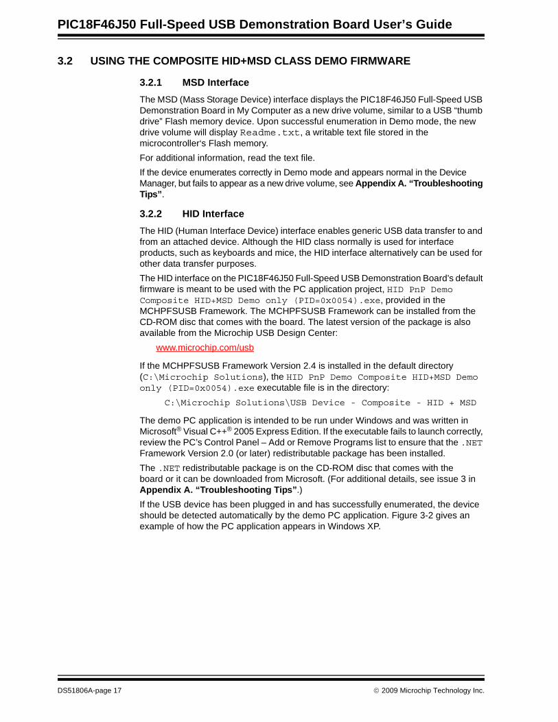
The demo PC application is intended to be run under Windows and was written in Microsoft® Visual C++® 2005 Express Edition. If the executable fails to launch correctly, review the PC’s Control Panel – Add or Remove Programs list to ensure that the .NET Framework Version 2.0 (or later) redistributable package has been installed.The .NET redistributable package is on the CD-ROM disc that comes with the board or it can be downloaded from Microsoft. (For additional details, see issue 3 in Appendix A. “Troubleshooting Tips”.)If the USB device has been plugged in and has successfully enumerated, the device should be detected automatically by the demo PC application. Figure 3-2 gives an example of how the PC application appears in Windows XP.
DS51806A-page 17 © 2009 Microchip Technology Inc.
Preprogrammed Firmware
FIGURE 3-2: HID DEMO APPLICATION
The demo PC application provides a simple graphical user interface for sending and receiving small amounts of example data to and from the HID interface on the USB device. Full source code for both this PC application and the demo firmware are included in the MCHPFSUSB Framework. Assuming the MCHPFSUSB Framework has been installed in the default location, the source code for both the firmware and PC application are found in the following directory:
C:\Microchip Solutions\USB Device - Composite - HID + MSD
The demo PC application can be used to toggle the LEDs on the demo board, determine the RB2 push button state and measure the analog voltage on the micro-controller’s RA0 I/O pin. The analog voltage on RA0 is measured by the ADC of the microcontroller and graphically displayed by the “ANx/POT Voltage” bar, as shown in Figure 3-2.If the PIC18F46J50 Full-Speed USB Demonstration Board is used as a stand-alone device, it is recommended that an adjustable external power supply (between 0V and 3.3V) be attached to the RA0 pin to provide a more interesting demo experience. If the board is used in conjunction with the PIC18 Explorer Board or the PICDEM HPC Explorer Board, the analog potentiometer on those boards, tied to RA0, can be adjusted to alter the HID demo’s voltage display bar.
3.3 USING THE HID BOOTLOADER FIRMWAREThe PIC18F46J50 Full-Speed USB Demonstration Board is preprogrammed with HID class USB bootloader firmware as well as the USB composite HID+MSD demo firmware. The HID bootloader is independent of the composite HID+MSD demo firmware.The bootloader firmware can be used to update the Flash memory contents of the PIC18F46J50 microcontroller, similar to using a dedicated ICSP based programmer. When the bootloader is used, a new .hex file can be programmed into the device by sending it directly over the USB cable to the PIC18F46J50.The HID bootloader firmware uses self-programming operations to update the Flash memory contents of the microcontroller.To use the HID bootloader:1. Launch the HID bootloader application by selecting:
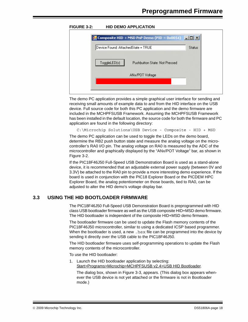
Start>Programs>Microchip>MCHPFSUSB v2.4>USB HID Bootloader.The dialog box, shown in Figure 3-3, appears. (This dialog box appears when-ever the USB device is not yet attached or the firmware is not in Bootloader mode.)
© 2009 Microchip Technology Inc. DS51806A-page 18
PIC18F46J50 Full-Speed USB Demonstration Board User’s Guide
FIGURE 3-3: USB HID BOOTLOADER APPLICATION – NO DEVICE
2. Plug the PIC18F46J50 Full-Speed USB Demonstration Board into a free USB port.3. Place the board in the Bootloader mode by pressing and holding down the S2
push button (RB2 I/O pin). While still holding down the S2 push button, momen-tarily press and release the MCLR push button (S4) to reset the device, keeping the S2 button depressed until after the device has come out of Reset.The bootloader firmware performs a quick check of the RB2 I/O pin after coming out of Reset to determine if the device should enter Bootloader or normal Demo mode.
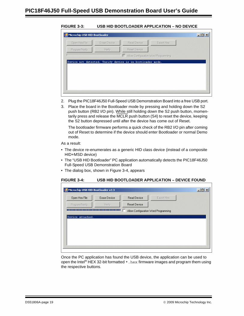
As a result:• The device re-enumerates as a generic HID class device (instead of a composite
HID+MSD device)• The “USB HID Bootloader” PC application automatically detects the PIC18F46J50
Full-Speed USB Demonstration Board• The dialog box, shown in Figure 3-4, appears
FIGURE 3-4: USB HID BOOTLOADER APPLICATION – DEVICE FOUND
Once the PC application has found the USB device, the application can be used to open the Intel® HEX 32-bit formatted *.hex firmware images and program them using the respective buttons.
DS51806A-page 19 © 2009 Microchip Technology Inc.
Preprogrammed Firmware
MPLAB IDE can be used to create these firmware image files by:1. Building a firmware project and using a modified linker script necessary for the
bootloader.2. Selecting File>Export and specifying the file format, INHX32.By default, the precompiled demo .hex files included in the MCHPFSUSB Framework distribution can be programmed using the USB bootloader application. The demo’s firmware projects were created using the appropriately modified linker script, so the demos should work directly with the bootloader.Programming a new firmware image using the bootloader does not erase or overwrite the bootloader firmware inside the microcontroller. To execute newly programmed firm-ware with the bootloader application, reset the microcontroller by pressing the MCLR push button.For more details on using the HID USB bootloader, see the getting started guide for the bootloader in the MCHPFSUSB Framework documentation directory. If the default installation was used, that document is in the following directory:C:\Microchip Solutions\Microchip\Usb\Documentation\Getting Started
© 2009 Microchip Technology Inc. DS51806A-page 20
PIC18F46J50 FULL-SPEED USBDEMONSTRATION BOARD
USER’S GUIDE
Appendix A. Troubleshooting Tips
This appendix gives solutions for common issues.
Problem 1:The USB device enumerates correctly in Demo mode (and appears normal in the Device Manager), but a new drive volume does not appear for the MSD interface.
Resolution:See if the target system has a drive letter conflict.Common operating systems typically assign USB mass storage volumes (such as Flash memory devices and detachable CD-ROM or floppy drives) to the next available drive letter (often “E:”). If, however, the automatically assigned drive letter has already been assigned to some other device (such as a mapped network drive), a conflict can occur with some Windows operating systems.See Microsoft Knowledge Base article 297694 at the following link:
http://support.microsoft.com/kb/297694To resolve this issue, do one of the following:• Obtain the hotfix available from Microsoft• Manually reassign the conflicting drive volume (such as a mapped network drive)
with a drive letter that is later in the alphabet (such as Z:)
Problem 2:The USB device does not enumerate or appear in the Device Manager.
Resolution:Verify the following:• The microcontroller is powered• Jumper cap, JP3, is installed so that the demonstration board is obtaining power
from the USB cable• The microcontroller was programmed with the correct firmwareThe factory default firmware can be restored onto the microcontroller any time by using the ICSP programming header and programming the microcontroller with the file, PIC18F46J50 FS USB Demo Board Factory Hex 23 Jan 2009.hex. To do this:1. Launch the MPLAB IDE application and select the ICSP programmer and the
correct device (PIC18F46J50).2. Select File>Import.3. Select the file, PIC18F46J50 FS USB Demo Board Factory Hex 23 Jan
2009.hex.4. Attach the programmer and select Programmer>Program.
© 2009 Microchip Technology Inc. DS51806A-page 21
Problem 3:When a PC application, such as the HID bootloader and HID PnP Demo Composite HID+MSD Demo only (PID=0x0054).exe are launched, an error message appears and the application does not open correctly.
Resolution:The HID bootloader and HID PnP demo applications were developed in the Microsoft Visual C++ 2005 Express Edition development environment and will not run without the PC having the .NET Framework 2.0 (or higher) redistributable package installed. If the .NET package has not been installed, do so.The .NET Framework redistributable package is available in the MCHPFSUSB Framework on the CD-ROM disc that comes with the PIC18F46J50 Full-Speed USB Demonstration Board. Alternately, the .NET package can be downloaded from the Microsoft web site:
Go to the Microsoft Download Center and use the key words, “.NET Framework”.The Windows Vista and Windows 7 operating systems already have support built-in for .NET Framework 2.0 or later, so installation of the .NET package is unnecessary. Earlier Windows operating systems, however, will require the package installation.
© 2009 Microchip Technology Inc. DS51806A-page 22

PIC18F46J50 FULL-SPEED USBDEMONSTRATION BOARD
USER’S GUIDE
Appendix B. Board Schematics
Figure B-1 through Figure B-3 show the schematics for the PIC18F46J50 Full-Speed USB Demonstration Board.
When designing the PIC18F46J50 Full-Speed USB Demonstration Board, special care was taken to make the board USB 2.0, full-speed compliant. It is suggested that those designing new USB applications review section 7.2 of the official USB 2.0 specifica-tions. That section includes important information related to power management (such as board inrush current) specifications necessary to pass USB compliance tests.
© 2009 Microchip Technology Inc. DS51806A-page 23
Board Schematics
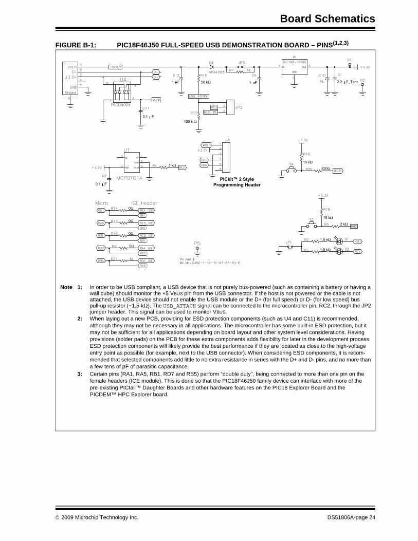
FIGURE B-1: PIC18F46J50 FULL-SPEED USB DEMONSTRATION BOARD – PINS(1,2,3)
1 F
0.1 F
1 F 2.2 F_Tant
0.1 F
56 k
100 k
15 k
8202 k
2 k
1.5 k
1.5 k
0
0
0
0
15 k
PICkit™ 2 StyleProgramming Header
Note 1: In order to be USB compliant, a USB device that is not purely bus-powered (such as containing a battery or having a wall cube) should monitor the +5 VBUS pin from the USB connector. If the host is not powered or the cable is not attached, the USB device should not enable the USB module or the D+ (for full speed) or D- (for low speed) bus pull-up resistor (~1.5 kΩ). The USB_ATTACH signal can be connected to the microcontroller pin, RC2, through the JP2 jumper header. This signal can be used to monitor VBUS.
2: When laying out a new PCB, providing for ESD protection components (such as U4 and C11) is recommended, although they may not be necessary in all applications. The microcontroller has some built-in ESD protection, but it may not be sufficient for all applications depending on board layout and other system level considerations. Having provisions (solder pads) on the PCB for these extra components adds flexibility for later in the development process. ESD protection components will likely provide the best performance if they are located as close to the high-voltage entry point as possible (for example, next to the USB connector). When considering ESD components, it is recom-mended that selected components add little to no extra resistance in series with the D+ and D- pins, and no more than a few tens of pF of parasitic capacitance.
3: Certain pins (RA1, RA5, RB1, RD7 and RB5) perform “double duty”, being connected to more than one pin on the female headers (ICE module). This is done so that the PIC18F46J50 family device can interface with more of the pre-existing PICtail™ Daughter Boards and other hardware features on the PIC18 Explorer Board and the PICDEM™ HPC Explorer board.
© 2009 Microchip Technology Inc. DS51806A-page 24
PIC18F46J50 Full-Speed USB Demonstration Board User’s Guide
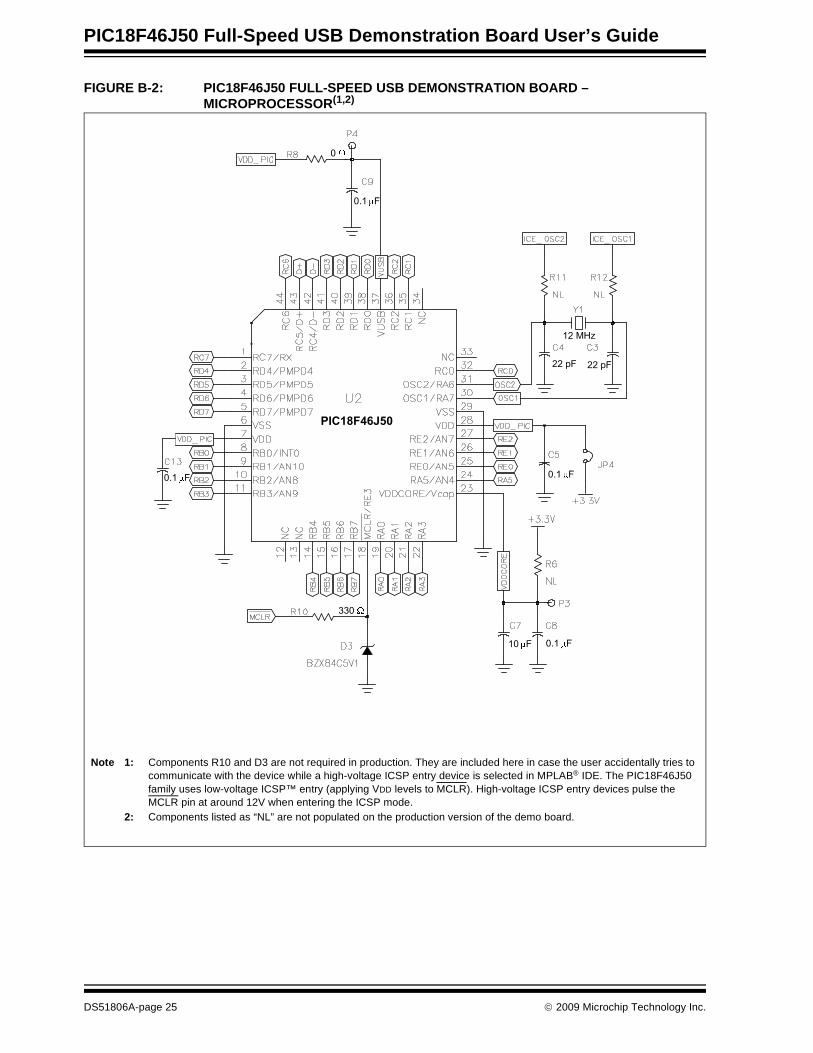
FIGURE B-2: PIC18F46J50 FULL-SPEED USB DEMONSTRATION BOARD – MICROPROCESSOR(1,2)
330
0
0.1 F
22 pF
12 MHz
22 pF
0.1 F
0.1 F10 F
0.1 F
PIC18F46J50
Note 1: Components R10 and D3 are not required in production. They are included here in case the user accidentally tries to communicate with the device while a high-voltage ICSP entry device is selected in MPLAB® IDE. The PIC18F46J50 family uses low-voltage ICSP™ entry (applying VDD levels to MCLR). High-voltage ICSP entry devices pulse the MCLR pin at around 12V when entering the ICSP mode.
2: Components listed as “NL” are not populated on the production version of the demo board.
DS51806A-page 25 © 2009 Microchip Technology Inc.
Board Schematics
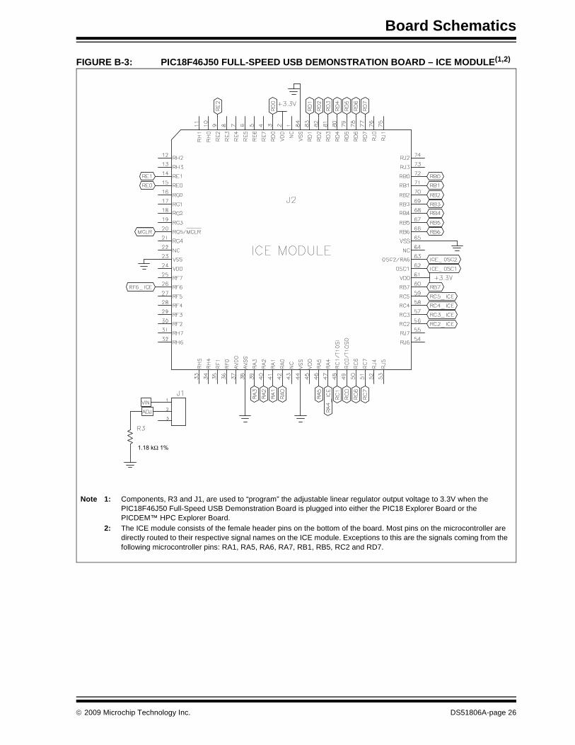
FIGURE B-3: PIC18F46J50 FULL-SPEED USB DEMONSTRATION BOARD – ICE MODULE(1,2)
1.18 k 1%
Note 1: Components, R3 and J1, are used to “program” the adjustable linear regulator output voltage to 3.3V when the PIC18F46J50 Full-Speed USB Demonstration Board is plugged into either the PIC18 Explorer Board or the PICDEM™ HPC Explorer Board.
2: The ICE module consists of the female header pins on the bottom of the board. Most pins on the microcontroller are directly routed to their respective signal names on the ICE module. Exceptions to this are the signals coming from the following microcontroller pins: RA1, RA5, RA6, RA7, RB1, RB5, RC2 and RD7.
© 2009 Microchip Technology Inc. DS51806A-page 26
PIC18F46J50 Full-Speed USB Demonstration Board User’s Guide
NOTES:
DS51806A-page 27 © 2009 Microchip Technology Inc.
DS51806A-page 28 © 2009 Microchip Technology Inc.
AMERICASCorporate Office2355 West Chandler Blvd.Chandler, AZ 85224-6199Tel: 480-792-7200 Fax: 480-792-7277Technical Support: http://support.microchip.comWeb Address: www.microchip.comAtlantaDuluth, GA Tel: 678-957-9614 Fax: 678-957-1455BostonWestborough, MA Tel: 774-760-0087 Fax: 774-760-0088ChicagoItasca, IL Tel: 630-285-0071 Fax: 630-285-0075ClevelandIndependence, OH Tel: 216-447-0464 Fax: 216-447-0643DallasAddison, TX Tel: 972-818-7423 Fax: 972-818-2924DetroitFarmington Hills, MI Tel: 248-538-2250Fax: 248-538-2260KokomoKokomo, IN Tel: 765-864-8360Fax: 765-864-8387Los AngelesMission Viejo, CA Tel: 949-462-9523 Fax: 949-462-9608Santa ClaraSanta Clara, CA Tel: 408-961-6444Fax: 408-961-6445TorontoMississauga, Ontario, CanadaTel: 905-673-0699 Fax: 905-673-6509
ASIA/PACIFICAsia Pacific OfficeSuites 3707-14, 37th FloorTower 6, The GatewayHarbour City, KowloonHong KongTel: 852-2401-1200Fax: 852-2401-3431Australia - SydneyTel: 61-2-9868-6733Fax: 61-2-9868-6755China - BeijingTel: 86-10-8528-2100 Fax: 86-10-8528-2104China - ChengduTel: 86-28-8665-5511Fax: 86-28-8665-7889China - Hong Kong SARTel: 852-2401-1200 Fax: 852-2401-3431China - NanjingTel: 86-25-8473-2460Fax: 86-25-8473-2470China - QingdaoTel: 86-532-8502-7355Fax: 86-532-8502-7205China - ShanghaiTel: 86-21-5407-5533 Fax: 86-21-5407-5066China - ShenyangTel: 86-24-2334-2829Fax: 86-24-2334-2393China - ShenzhenTel: 86-755-8203-2660 Fax: 86-755-8203-1760China - WuhanTel: 86-27-5980-5300Fax: 86-27-5980-5118China - XiamenTel: 86-592-2388138 Fax: 86-592-2388130China - XianTel: 86-29-8833-7252Fax: 86-29-8833-7256China - ZhuhaiTel: 86-756-3210040 Fax: 86-756-3210049
ASIA/PACIFICIndia - BangaloreTel: 91-80-3090-4444 Fax: 91-80-3090-4080India - New DelhiTel: 91-11-4160-8631Fax: 91-11-4160-8632India - PuneTel: 91-20-2566-1512Fax: 91-20-2566-1513Japan - YokohamaTel: 81-45-471- 6166 Fax: 81-45-471-6122Korea - DaeguTel: 82-53-744-4301Fax: 82-53-744-4302Korea - SeoulTel: 82-2-554-7200Fax: 82-2-558-5932 or 82-2-558-5934Malaysia - Kuala LumpurTel: 60-3-6201-9857Fax: 60-3-6201-9859Malaysia - PenangTel: 60-4-227-8870Fax: 60-4-227-4068Philippines - ManilaTel: 63-2-634-9065Fax: 63-2-634-9069SingaporeTel: 65-6334-8870Fax: 65-6334-8850Taiwan - Hsin ChuTel: 886-3-572-9526Fax: 886-3-572-6459Taiwan - KaohsiungTel: 886-7-536-4818Fax: 886-7-536-4803Taiwan - TaipeiTel: 886-2-2500-6610 Fax: 886-2-2508-0102Thailand - BangkokTel: 66-2-694-1351Fax: 66-2-694-1350
EUROPEAustria - WelsTel: 43-7242-2244-39Fax: 43-7242-2244-393Denmark - CopenhagenTel: 45-4450-2828 Fax: 45-4485-2829France - ParisTel: 33-1-69-53-63-20 Fax: 33-1-69-30-90-79Germany - MunichTel: 49-89-627-144-0 Fax: 49-89-627-144-44Italy - Milan Tel: 39-0331-742611 Fax: 39-0331-466781Netherlands - DrunenTel: 31-416-690399 Fax: 31-416-690340Spain - MadridTel: 34-91-708-08-90Fax: 34-91-708-08-91UK - WokinghamTel: 44-118-921-5869Fax: 44-118-921-5820
WORLDWIDE SALES AND SERVICE
02/04/09


![Untitled-2 []€¦ · Menu Select Menu Select Pcrsonalisation-configuration Define the vehicle parameters Clisplag configuration language Board Computer / System Settings Citroen](https://img.pdfslide.us/doc/110x75/5f235dfa6fba2b221c1f35d2/untitled-2-menu-select-menu-select-pcrsonalisation-configuration-define-the.jpg)
![N63 and S63 Engine: Valve Seal Replacement1. Select “Service Reference” from the top menu bar. 2. Select “Service Videos.” 3. Select “General Search.” 4. Select “[11]](https://img.pdfslide.us/doc/110x75/5fcc3fe5576d073bb459cdea/n63-and-s63-engine-valve-seal-replacement-1-select-aoeservice-referencea-from.jpg)
![1 Select the [Digital Photo Professional] menu - B&H Photo Video](https://img.pdfslide.us/doc/110x75/62038e5fda24ad121e4ac9b0/1-select-the-digital-photo-professional-menu-bamph-photo-video.jpg)