Embed Size (px)
Citation preview

iii
PI Interface for Siemens Spectrum
Version 1.0.9.x

OSIsoft, LLC
777 Davis St., Suite 250
San Leandro, CA 94577 USA
Tel: (01) 510-297-5800
Fax: (01) 510-357-8136
Web: http://www.osisoft.com
OSIsoft Australia • Perth, Australia
OSIsoft Europe GmbH • Frankfurt, Germany
OSIsoft Asia Pte Ltd. • Singapore
OSIsoft Canada ULC • Montreal & Calgary, Canada
OSIsoft, LLC Representative Office • Shanghai, People’s Republic of China
OSIsoft Japan KK • Tokyo, Japan
OSIsoft Mexico S. De R.L. De C.V. • Mexico City, Mexico
OSIsoft do Brasil Sistemas Ltda. • Sao Paulo, Brazil
PI Interface for Siemens Spectrum
Copyright: © 2000-2014 OSIsoft, LLC. All rights reserved.
No part of this publication may be reproduced, stored in a retrieval system, or transmitted, in any form or by any means, mechanical, photocopying, recording, or otherwise, without the prior written permission of OSIsoft, LLC.
OSIsoft, the OSIsoft logo and logotype, PI Analytics, PI ProcessBook, PI DataLink, ProcessPoint, PI Asset Framework(PI-AF), IT Monitor, MCN Health Monitor, PI System, PI ActiveView, PI ACE, PI AlarmView, PI BatchView, PI Data Services, PI Manual Logger, PI ProfileView, PI WebParts, ProTRAQ, RLINK, RtAnalytics, RtBaseline, RtPortal, RtPM, RtReports and RtWebParts are all trademarks of OSIsoft, LLC. All other trademarks or trade names used herein are the property of their respective owners.
U.S. GOVERNMENT RIGHTS
Use, duplication or disclosure by the U.S. Government is subject to restrictions set forth in the OSIsoft, LLC license agreement and as provided in DFARS 227.7202, DFARS 252.227-7013, FAR 12.212, FAR 52.227, as applicable. OSIsoft, LLC.
Published: 01/2014
PI Interface for Siemens Spectrum iii
Table of Contents
Chapter 1. Introduction ................................................................................................ 1
Reference Manuals ............................................................................................. 2 Supported Operating Systems ............................................................................ 2 Supported Features............................................................................................. 2 Diagram of Hardware Connection ....................................................................... 5
Chapter 2. Principles of Operation .............................................................................. 7
Overview ............................................................................................................. 7 Multi-process Design Overview ......................................................................... 10 Workflow ............................................................................................................ 10 Protocol ............................................................................................................. 11
Chapter 3. Installation Checklist ................................................................................ 13
Data Collection Steps ........................................................................................ 13 Notes on Upgrading .......................................................................................... 14
Chapter 4. Interface Installation on UNIX .................................................................. 17
Naming Conventions and Requirements .......................................................... 18 Interface Directories .......................................................................................... 18
PIHOME Directory .................................................................................. 18 Interface Installation Directory ................................................................ 18 Interface Directories (for multiple PI-API installation) ............................. 18
Interface Installation Procedure ........................................................................ 19 Sending Data to Multiple Collectives ...................................................... 19
Chapter 5. Digital States ............................................................................................. 21
Chapter 6. PointSource .............................................................................................. 23
Chapter 7. PI Point Configuration .............................................................................. 25
Point Attributes .................................................................................................. 25 Tag .......................................................................................................... 25 PointSource ............................................................................................ 26 PointType ................................................................................................ 26 Location1 ................................................................................................ 26 Location2 ................................................................................................ 27 Location3 ................................................................................................ 27 Location4 ................................................................................................ 27 Location5 ................................................................................................ 27 UserInt1 .................................................................................................. 27 InstrumentTag ......................................................................................... 28 ExDesc .................................................................................................... 28 Scan ........................................................................................................ 28 Shutdown ................................................................................................ 28
Table of Contents
iv
Chapter 8. Startup Command File ............................................................................. 31
Configuring the Interface with PI ICU ................................................................ 31 Configure a UNIX- or VMS-based Interface ...................................................... 32 Scan Class Configuration .................................................................................. 36 Command-line Parameters ............................................................................... 38
Chapter 9. Interface Node Clock ................................................................................ 45
Chapter 10. Security ................................................................................................. 47
UNIX .................................................................................................................. 47
Chapter 11. Starting / Stopping the Interface on UNIX ........................................... 49
Chapter 12. Buffering ............................................................................................... 51
How Buffering Works......................................................................................... 51 Buffering and PI Server Security ....................................................................... 52 Configuring Buffering on an Interface Node ...................................................... 52 Example piclient.ini File ..................................................................................... 54
Chapter 13. Interface Diagnostics Configuration ................................................... 55
Configuring Performance Points on UNIX......................................................... 55 Interface Health Monitoring Points .................................................................... 56 I/O Rate Point .................................................................................................... 56 Configuring I/O Rate Tags On UNIX ................................................................. 56
Configuring PI Point on the PI Server ..................................................... 56 Configuration on the Interface Node ....................................................... 56
Interface Status Point Configuration ................................................................. 57 Available Statuses .................................................................................. 58
Appendix A. Error and Informational Messages ..................................................... 61
Message Logs ................................................................................................... 61 Messages .......................................................................................................... 61
Error Messages ....................................................................................... 61 Spectrum States ..................................................................................... 64
System Errors and PI Errors ............................................................................. 65
Appendix B. Terminology ........................................................................................ 67
Appendix C. Technical Support and Resources ..................................................... 71
Before You Call or Write for Help ........................................................... 71 Help Desk and Telephone Support......................................................... 71 Search Support ....................................................................................... 72 Email-based Technical Support .............................................................. 72 Online Technical Support ....................................................................... 72 Remote Access ....................................................................................... 73 On-site Service ....................................................................................... 73 Knowledge Center .................................................................................. 73 Upgrades ................................................................................................ 73 OSIsoft Virtual Campus (vCampus) ........................................................ 73

PI Interface for Siemens Spectrum v
Appendix D. Revision History .................................................................................. 75

PI Interface for Siemens Spectrum 1
Chapter 1. Introduction
The PI Interface for Siemens Spectrum, from here on called the PI-Spectrum interface, will
collect analog and digital value and quality data from the Spectrum EMS system and send
them to the PI System. The interface does not support the collection of counters at this time.
The interface is a fully compliant Spectrum Program. This includes the following:
• The interface starts and stops on command by Spectrum, with the SoftInit and EndProg
Softbus signals.
• The interface supports hot failover, following the Process Control (PC) and StandBy (SB)
Softbus states.
Note: Please contact Siemens prior to purchasing and installing this interface as it requires enhancements to the Spectrum system.
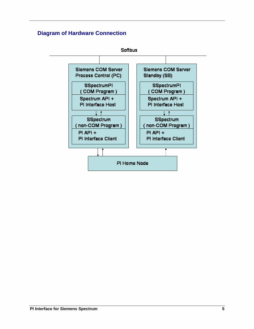
A copy of the interface runs independently on both of the COM servers present in a Spectrum
system. (COM stands for COMmunicator which is not to be confused with Microsoft COM.)
Only the interface communicating with the COM server that is in the Process Control state
will send data to the PI System. This is the one that is considered “hot.” A typical operation
Spectrum system in operation will always consist of two COMs.
Starting in version 1.0.8 of the Interface, more than 2 instances of the Interface may be
configured to service the same sets of tags. The additional interface instances, configured to
read a specified Data of Record (DOR) digital Spectrum value, send data only when their
system is the DOR. This extra level of redundancy works in conjunction with the Process
Control and Standby states.
The Interface also has an ICU control for configuring the Interface startup parameters. This
Graphical-based utility only runs on Microsoft Windows. Unlike most interfaces, there is no
accompanying startup batch file to run the Interface, as Spectrum programs aren’t designed to
have them. Only the server name to connect to (PIHOMENODE=<server>) and the port
(PORT=5450) are required in the piclient.ini file in the piapi/dat directory.
Note: The value of [PIHOME] variable is the directory where the PI-API is installed.
Introduction
2
Reference Manuals
OSIsoft
PI Server manuals
PI API Installation Instructions manual
UniInt Interface User Manual
Siemens
Spectrum User Manual
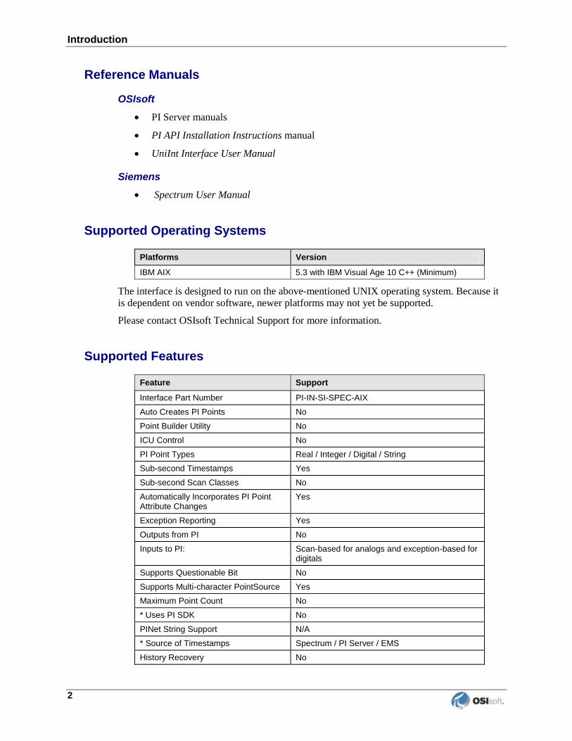
Supported Operating Systems
Platforms Version
IBM AIX 5.3 with IBM Visual Age 10 C++ (Minimum)
The interface is designed to run on the above-mentioned UNIX operating system. Because it
is dependent on vendor software, newer platforms may not yet be supported.
Please contact OSIsoft Technical Support for more information.
Supported Features
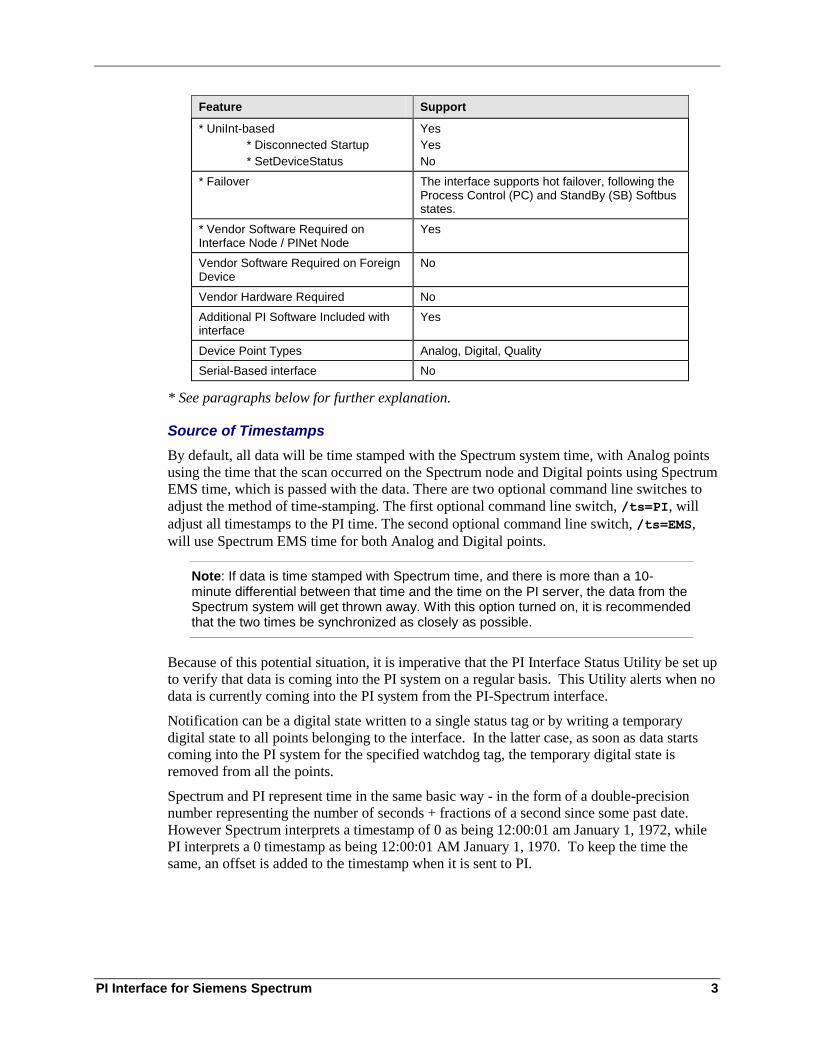
Feature Support
Interface Part Number PI-IN-SI-SPEC-AIX
Auto Creates PI Points No
Point Builder Utility No
ICU Control No
PI Point Types Real / Integer / Digital / String
Sub-second Timestamps Yes
Sub-second Scan Classes No
Automatically Incorporates PI Point Attribute Changes
Yes
Exception Reporting Yes
Outputs from PI No
Inputs to PI: Scan-based for analogs and exception-based for digitals
Supports Questionable Bit No
Supports Multi-character PointSource Yes
Maximum Point Count No
* Uses PI SDK No
PINet String Support N/A
* Source of Timestamps Spectrum / PI Server / EMS
History Recovery No
PI Interface for Siemens Spectrum 3
Feature Support
* UniInt-based
* Disconnected Startup
* SetDeviceStatus
Yes
Yes
No
* Failover The interface supports hot failover, following the Process Control (PC) and StandBy (SB) Softbus states.
* Vendor Software Required on Interface Node / PINet Node
Yes
Vendor Software Required on Foreign Device
No
Vendor Hardware Required No
Additional PI Software Included with interface
Yes
Device Point Types Analog, Digital, Quality
Serial-Based interface No
* See paragraphs below for further explanation.
Source of Timestamps
By default, all data will be time stamped with the Spectrum system time, with Analog points
using the time that the scan occurred on the Spectrum node and Digital points using Spectrum
EMS time, which is passed with the data. There are two optional command line switches to
adjust the method of time-stamping. The first optional command line switch, /ts=PI, will
adjust all timestamps to the PI time. The second optional command line switch, /ts=EMS,
will use Spectrum EMS time for both Analog and Digital points.
Note: If data is time stamped with Spectrum time, and there is more than a 10-minute differential between that time and the time on the PI server, the data from the Spectrum system will get thrown away. With this option turned on, it is recommended that the two times be synchronized as closely as possible.
Because of this potential situation, it is imperative that the PI Interface Status Utility be set up
to verify that data is coming into the PI system on a regular basis. This Utility alerts when no
data is currently coming into the PI system from the PI-Spectrum interface.
Notification can be a digital state written to a single status tag or by writing a temporary
digital state to all points belonging to the interface. In the latter case, as soon as data starts
coming into the PI system for the specified watchdog tag, the temporary digital state is
removed from all the points.
Spectrum and PI represent time in the same basic way - in the form of a double-precision
number representing the number of seconds + fractions of a second since some past date.
However Spectrum interprets a timestamp of 0 as being 12:00:01 am January 1, 1972, while
PI interprets a 0 timestamp as being 12:00:01 AM January 1, 1970. To keep the time the
same, an offset is added to the timestamp when it is sent to PI.
Introduction
4
UniInt-based
UniInt stands for Universal Interface. UniInt is not a separate product or file; it is an
OSIsoft-developed template used by developers and is integrated into many interfaces,
including this interface. The purpose of UniInt is to keep a consistent feature set and behavior
across as many of OSIsoft’s interfaces as possible. It also allows for the very rapid
development of new interfaces. In any UniInt-based interface, the interface uses some of the
UniInt-supplied configuration parameters and some interface-specific parameters. UniInt is
constantly being upgraded with new options and features.
The UniInt Interface User Manual is a supplement to this manual.
Disconnected Start-Up
The PI Spectrum interface is built with a version of UniInt that supports disconnected start-
up. Disconnected start-up is the ability to start the interface without a connection to the PI
Server. This functionality is enabled by adding /cachemode to the list of start-up parameters
or by enabling disconnected startup using the ICU. Refer to the UniInt Interface User Manual
for more details on UniInt disconnected startup.
Failover
The interface supports “hot” failover following the Spectrum Softbus Process Control (PC)
and StandBy (SB) states. A failure in the interface or one of the ancillary processes, such as
the buffer service, will trigger a failover to the Standby COM server. However, if the PI
server itself is shut down or a network failure occurs between the Interface node and the PI
server node, this will not cause a failover event. Instead, events are buffered by the Interface
until such time as the PI server becomes available again. Helping to ease the transition
between the separate copies of the interfaces running on each server, both instances collect
data at all times, as well as receive point updates from the PI server. However, only the “hot”
COM server will send data to the PI system.
Vendor Software Required
Siemens provides an IDDUG record to allow the user to select which Spectrum points will be
collected in PI. IDDUG records are formatted text records that are used to enter data into the
Spectrum Primitive Database.
Additionally Siemens provides an API that must be linked with the Interface before the
Interface can run.
Device Point Types
Analog and Digital values are supported as well as quality values.
PI Interface for Siemens Spectrum 5
Diagram of Hardware Connection

PI Interface for Siemens Spectrum 7
Chapter 2. Principles of Operation
Overview
The PI-Spectrum interface runs as two processes: sspec_pi is a fully compliant Spectrum
program and therefore follows the Spectrum program operating guidelines; the UniInt process
called SSpectrum is spawned by sspec_pi at startup. As the Spectrum system does not
allow for the passing of command-line arguments to programs in the manner in which
normally interfaces pass parameters, all the startup parameters must be configured with the
included PI-ICU control on a Windows node and not the machine on which the Interface is
running.
The two processes communicate by sending messages across a shared memory segment.
Once the UniInt process is started, the Spectrum process enters a loop where it awaits new
commands from the UniInt process, acts on them, and sends the results back. The UniInt
process then writes data to PI and sends status/error messages to the
$PIHOME/dat/pimesslogfile file. More information on this topic follows in the section
titled “Multi-process Design Overview.”
The UniInt process reads the piclient.ini file’s PIHOMENODE and PORT entries to
determine which PI server to use. This file is located in the piapi/dat directory as
indicated by the required PIHOME environment variable. Once this is determined, the
process reads the parameters specified by the user with the PI-ICU control, and begins full
operations.
Like most Windows-based Interfaces, but unlike any other UNIX Interface, the startup
parameters are configured from the PI-ICU rather than a startup file. Once the user has
configured the parameters, the PI-ICU creates a unique Digital State set with entries
containing each of the parameters. The name of the Digital State set is
InterfaceParameters_<API Node name>_sspectrum_1. Once the initial connection
is made to PI, the Digital State set can then be used.
Note: In addition to the Digital State set, a digital PI point is also created, one which uses this state set. The name of the point containing the Digital State set is also called InterfaceParameters_<API Node name>_sspectrum_1.
This interface supports disconnected startup. Once the startup parameters are read from the PI
server, they are cached locally in the $PIHOME/dat directory, in the file
InterfaceParameters_<API Node name>_sspectrum_1.dat. The interface will keep
the file up to date if the startup parameters change.
Some parameters indicate PI point attributes that all points serviced by the interface must
have in common and other parameters provide miscellaneous directives for operational
behavior. A detailed discussion of these parameters is included later in this document.
Principles of Operation
8
Due to the need for the Spectrum system to be the “master” in the relationship with the
interface, the interface performs certain actions that are not typical of standard OSIsoft
interfaces. One of the first actions taken immediately upon startup is the establishment of
communication with the Spectrum system, prior to UniInt making a connection to the PI
Server. If an ENDPROG signal is received from Spectrum indicating that the interface
should stop, the Interface performs the necessary clean up and shuts down. If a
piOWNCOMSTATE signal is received, the Interface will switch to the ProcessControl or
Standby state as dictated by Spectrum. This is used to perform “hot” failover in the event
there are two or more instances of the Interface running in such a configuration.
The interface then connects to the PI Home node, retrieves its startup parameters, loads all
relevant PI points, and constructs the mappings to Spectrum records and fields based upon
point attributes configured in the PI point database. This concludes interface initialization and
is identical for both interfaces running in a “hot-standby” configuration. Thereafter, the
standby interface’s only tasks are to keep updating its point list whenever the PI point
database is changed, and passively collect data from the Spectrum system, while the “hot”
interface updates its point list and actively transfers data to PI. Upon discovering that it has
become “hot,” the standby interface immediately commences data collection and the interface
that was “hot” ceases sending data to the PI system.
If the Spectrum system contains two COM servers, the user has the option of writing the
digital state INTF SHUT to points belonging to the interface in ProcessControl when it is
told to shut down. In this case, there is no more data collection and the user will want to be
notified. This situation is not expected to ever occur in a failover architecture.
If the Spectrum system only contains a single COM server, then the /stopstat=”intf
shut” parameter should be specified to ensure that INTF SHUT is written to all points when
an interface shutdown occurs.
A point in Spectrum is uniquely defined by defining the Norm, Info, and Nimset attributes.
The interface retrieves analog and digital values and quality data from Spectrum by different
methods. The Spectrum system is scanned for the collection of analog points at fixed
frequencies specified by the scan class used. This frequency typically matches the frequency
at which these points are collected by Spectrum from the field. The Spectrum system
contains a proprietary real-time, file-based database from which the interface collects its data.
These files are known as relations. There are many relations contained in a Spectrum system.
When it is time to service a scan class, the interface makes a separate call to Spectrum to get
the values and qualities for the points belonging to each relation. If an error is returned from
the call to read analog values and qualities, the digital state ERROR is written to all points
that were to be retrieved from the call. In addition, individual error codes can also be
returned from the call. If one of those fails, the digital state BAD INPUT is written to the
analog point value tag. Its associated quality tag will contain the value returned from the
Spectrum system.
For digital values, the values and qualities are returned any time the value or quality of a
digital point changes. If a digital value is read that does not match up any PI point in the
Interface, then it is discarded. Upon startup a call to Spectrum is made to retrieve the value
for all known digital points to provide baseline data. A separate call is made to retrieve the
current value for newly added digital points.

PI Interface for Siemens Spectrum 9
Note: Analog data from Spectrum is sent as float64 values. However, the user should consider specifying PI PointTypes of float32 for the majority of points to save 4 bytes of data per floating-point value. Very few points require float64 precision.
Because the collection of digitals is on an exception basis, the interface cannot determine if
connection has been lost to the Spectrum system with certainty. Therefore, it does not ever
write I/O Timeout to its points.
As with all UniInt-based interfaces, the Siemens Spectrum interface checks for point update
information from the PI server approximately once every two minutes. Changes may include
point attribute modifications, point deletion or removal from the interface, or additions to the
interface. When more than 25 changes are made within 2 minutes, the interface will switch to
checking for updates every 30 seconds, until the rate of updates slows.
Actions taken to modify, add or delete points can be I/O intensive. For analog data the
interface needs to make a call to Spectrum to return sorted data for a given scan class if a new
point has been added to it, a point has been deleted from it, or either the Tech ID (Location
3=Norm Element, Location 5=Info Number, Userint1=Nimset Number) or the
scan frequency has been edited for a PI point. In order to minimize the number of sort calls
made, the interface sends the list of points contained in a single scan class to Spectrum to be
sorted immediately prior to collection for the next scan period if a new point has been added,
deleted, or sustained an edit that requires a sort. If it is necessary to make modifications to
hundreds of points at a time, the best course of action is to stop the interface, make the
changes and then restart the interface. When a PI point is added to the interface or edited, if
the Location2 value is not within the range of 0 – 4, the digital state CONFIGURE is
written to the point.
A target COM server may be customized in a number of ways and each COM server may
define its own unique set of Relations. Before the interface can run for the first time, it must
be built on the target COM server. A script to build the interface is included.
The Interface provides a wide variety of Status information which the user can monitor from
PI. Almost any piece of information that can be retrieved from the log file can also be stored
and read directly from PI by configuring one or more Status Points. Some status information
applies to the entire Interface while more specific data may pertain to just one Scan Class.
The user may create any number of Status Points. The possible statuses are detailed below in
the section titled “Status Point Configuration.”
When running in a “hot” failover configuration, like any other point, a status point normally
reflects the status of the current primary instance of the Interface. However, it is possible to
configure a Status point to only report the status of one instance or another, even while the
Interface is running in standby mode. This can be accomplished by specifying the /pr
command-line parameter specifying a different point for each copy.
Previous versions added support for the Data of Record (DOR) flag. This enables more than 2
instances of the interface to service the same set of tags. Four new optional parameters:
/dor_noel, /dor_info, /dor_nimset, /dor_value configure the Tech ID and
Value of the DOR digital. This digital value is read periodically, and when this value
matches what the interface expects the interface will send data to the PI server. Note that the
DOR digital value must be configured on the Spectrum system before this feature can be
used.
Previous versions also added support for having multiple instances of the interface on the
same COM server each running against a different collective. See the section “Sending Data
to Multiple Collectives.”

Principles of Operation
10
Multi-process Design Overview
Once the Interface is installed properly, the process sspec_pi starts and shuts down with the
COM server. This Spectrum program does not send data directly to PI, but instead it spawns
the UniInt process called SSpectrum, which receives the data sent by the first process.
The two processes communicate by sending messages across a shared memory segment.
Once the UniInt process is started, the Spectrum process enters a loop where it awaits new
commands from the UniInt process, acts on them, then sends the results back. The UniInt
process then sends data off to PI and sends status/error messages to the
$PIHOME/dat/pimesslogfile file.
In a normal run, messages are sent back and forth at least once a second, either while
servicing scan-based or exception-based points. There are two ways for the Interface to end,
either naturally by an EndProg signal or by an abnormal failure occurring either on the
UniInt or Spectrum side. Both processes maintain a timer and exit in the event of a
communication failure. If communications fail after a period of time (10 seconds once the
connection to Spectrum is made), then the other process will report “Unable to get control
from the Client/Server.”
Before exiting, it is the responsibility of the Spectrum process to attempt to kill the UniInt
process. If it is the UniInt process that finds itself unable to communicate with Spectrum, then
it will exit assuming that Spectrum is down.
The Spectrum program will communicate normal startup, shutdown, and communication
messages, as well as communication errors using the piSendSpectrumError, which logs
them to the Spectrum log file.
Workflow
Spectrum periodically checks the shared memory segment.
UniInt writes the request to the buffer.
UniInt sends notification that it is done writing.
Spectrum reads the request from the buffer.
Once the message is complete, Spectrum acts on the message and UniInt waits for the
response.
Spectrum writes the response to the buffer.
Spectrum sends notification that it is done writing.
UniInt reads the response from the buffer.
Uniint processes the response and the cycle repeats.

PI Interface for Siemens Spectrum 11
Protocol
The first byte of the shared memory segment is set aside for signaling between the two
processes. Initially it is set to 0 and Spectrum waits until it is set to 1 by UniInt signaling a
new message is waiting. UniInt then waits until the byte is set back to 0, indicating the
response has arrived. This memory block acts as a semaphore.
The rest of the first 4 bytes are unused.
The second integer is reserved first for writing the ID of the function for the client to call,
then the return value for each function call from the host. No pointers are returned by any
function call.
Arguments can be broken down first by whether they are passed or returned. No parameter is
both passed and returned.
Each argument is serialized in a way that is well defined for that type:
Booleans are written as bytes. A set of Booleans is written together, followed by 0 bytes
to ensure 4-byte alignment.
Simple numbers are written simply as 4-byte Integers, floats, or 8-byte doubles.
Strings are written as a 4-byte size, followed by n bytes for the string, terminated by a 0
byte. Strings are padded with 0 bytes to ensure 4-byte alignment.
Vectors are written as a 4-byte number of elements, followed by n elements.
Maps are written as a 4-byte number of elements, followed by n pairs of key/value pairs.
Structures are written as individual fields in the order they appear in the structure, with no
separation between them except to maintain 4-byte alignment.

PI Interface for Siemens Spectrum 13
Chapter 3. Installation Checklist
If you are familiar with running PI data collection interface programs, this checklist helps you
get the interface running. If you are not familiar with PI interfaces, return to this section after
reading the rest of the manual in detail.
This checklist summarizes the steps for installing this interface. You need not perform a
given task if you have already done so as part of the installation of another interface. For
example, you only have to configure one instance of Buffering for every interface node
regardless of how many interfaces run on that node.
The Data Collection Steps below are required. Interface Diagnostics and Advanced Interface
Features are optional.
Data Collection Steps
1. Install the PI-Interface Configuration Utility (PI-ICU) on the PI server or another
Windows computer (which installs PI-SDK and PI-API).
2. Verify that PI-API has been installed on the COM server. Make sure the following
are true:
a. Install by running the following command: “pi.install –v0”
b. Buffering, IOrates, and Message services are set to start automatically when
the machine is rebooted.
c. The PIHOME environment variable has been set in the user’s login script to
point to the directory where the PI-API has been installed.
d. The piclient.ini file in $PIHOME/dat has an entry for the PIHOMENODE
which points to the PI server and another entry, PORT.
3. (Optional) If planning to send data to two collectives, then a second PI-API
installation is required to buffer to the second collective.
a. The _PIHOME1 environment variable must be set to point to PIHOME (the
first installation)
b. The _PIHOME2 environment variable must be set to point to the second
installation.
c. The piclient.ini file in $_PIHOME2/dat has an entry for the PIHOMENODE
which points to a PI server in the second collective.
d. Only the Buffering and IOrates services must be set to automatic on the
second PI-API installation. All messages are sent to the message log in the
first PI-API directory.

Installation Checklist
14
4. Install the interface(s) on the COM server. See the following section “Interface
Installation on UNIX” for more details.
5. Define digital states sets for digital tags.
6. Choose a PointSource; the default is “s”.
7. (Optional) Select which Spectrum points to collect via a script provided by Siemens.
8. (Optional) Create a file containing the initial list of Spectrum points to create via
another script provided by Siemens.
9. (Optional) Verify the initial points have been created successfully.
10. Configure performance points.
11. Configure status points.
12. Configure I/O Rate tag.
13. Configure the startup parameters with the PI-ICU.
14. Set interface node clock.
15. Set up security.
16. Start the interface without buffering.
17. Verify data.
18. Stop interface, start buffering, start interface.
19. Add sspec_pi1_# to the sitestart script in $PIHOME/bin
20. (Optional) If planning to send data to multiple collectives, add sspec_PI2_# to the
sitestart script in $_PIHOME2/bin
Notes on Upgrading
After stopping the Interface, buffering and the other services (with the pistop2 script),
installing the new version and restarting you may encounter error messages such as this:
bufserv>PI-API> APIBUFFER: Error creating memory handle - errno is
17
bufserv>PI-API (913588) - PI74AWS> APIBUFFER: Unable to create
primary shared memory buffer.
The problem most likely in this case is that bufserv did not cleanly shut down. To clean up
bufserv. Either reboot or do the following steps:
1. Run pistop2 again
2. Run ipcs –bp
3. Examine the output of the command. There should not be any "Message Queues",
"Shared Memory", or "Semaphores" still around that are owned by the piadmin
process (assuming the PI processes are run as piadmin, if they are run by a common
user then it may be impossible to identify the resources and a reboot may be the only
option to clear things up without interfering with any other processes.) If you can
identify the resources owned by bufserv then continue

PI Interface for Siemens Spectrum 15
4. If "Message Queues" are left over, please remove them with the command:
ipcrm -q <ID>
where <ID> is the ID of the message queue as displayed in the second column of the
"ipc -bp" output.
5. If "Shared Memory" are left over, please remove them with the command:
ipcrm -m <ID>
6. If "Semaphore" are left over, please remove them with the command:
ipcrm -s <ID>
7. Restart the interface and buffering with the pistart2 script


PI Interface for Siemens Spectrum 17
Chapter 4. Interface Installation on UNIX
One of the first issues that must be resolved is where the interface should be installed. Should
the interface be installed on the PI Server node or on a remote interface node? OSIsoft
recommends that the interface be installed on a remote interface node. The primary function
of the server node is to archive data and to service the clients that request that data. The PI
Server should not need to compete with interfaces for the machine’s resources. If the
interface is installed on a remote interface node, then the PI API must be installed on that
node before the interface is installed. Refer to the PI API manual.
When the interface is installed on a interface node, it is also a good idea to install and run
Bufserv on the interface node. Bufserv is a utility program that provides the capability to
store and forward events to a PI Server, allowing continuous data collection when the server
is down for maintenance, upgrades, backups, and unexpected failures. It is not critical to
install Bufserv before the initial installation of the interface. In fact, it is recommended that
Bufserv be installed after the interface has been shown to work to ease troubleshooting. Refer
to the PI API manual for installation instructions and additional information on Bufserv.
Currently there is no PI Buffer Subsystem for the UNIX platform. PI API Buffer Server is
the only type of buffering available for the UNIX platform.
If the interface is installed on the PI Server node, the advantage of using Bufserv is
diminished because it is no longer needed to protect against network failures. Bufserv would
still allow data to be collected when the PI Server is brought down for routine maintenance,
but this advantage must be weighed against the additional load that Bufserv incurs on the
server. Typically, users do not choose to run Bufserv on the PI Server node. If Bufserv is
used on the server node, make sure that Bufserv is started before any interfaces by the startup
script for PI.
If the interface is installed on a server node, the interface should be configured to start and
stop in conjunction with the PI Server. If the interface is installed on a interface node, then
the interface should be configured to start and stop with the PI API. Site-specific scripts can
be edited for this purpose, as described in the installation procedure below. The PI Server and
the PI API, in turn, can be configured to start and stop automatically when the system is shut
down or rebooted. Procedures for automatic startup and shutdown of PI or the PI API are
platform specific. The automation procedures are discussed in the PI System Management
chapter of the PI Server manuals.
The interface is split into two separate and distinct programs running on the COM server;
communicating via a shared memory segment. One, sspec_pi is a Spectrum Program that
will be started by the COM server. The second - SSpectrum is a non-Spectrum program
which is started and ended by the first program.
The sspec_pi process runs nearly silently, except for startup messages which get written to
the Spectrum log file. It must be built on the COM server – linked with libraries supplied by
OSIsoft and the Spectrum API supplied by Siemens. Once this is done, it should be installed
to stop and start as a regular Spectrum process.
Interface Installation on UNIX
18
SSpectrum is a program delivered by OSIsoft, relaying data from Spectrum to the PI Server,
and logging all messages in the pimesslog file as other PI Interfaces do. The difference is that
this program can’t run without the first process.
Naming Conventions and Requirements
In the installation procedure below, it is assumed that the name of the Spectrum program is
sspec_pi, and the name of the non-Spectrum program is SSpectrum. Starting with version
1.0.5.1, the interface supports running multiple versions of the interface on a single COM
box.
Interface Directories
PIHOME Directory
PIHOME is an environment variable that points to the base directory where the PI API is
installed. The setting of environment variables is discussed in the PI API manual.
Interface Installation Directory
sspec_pi must be built and installed on each COM server before it can be run. Siemens
provides the installation procedure for how to do this. The location where the program resides
may differ between each Installation depending on how the COM server is configured. When
configuring multiple instances of the interface, you must create a copy of sspec_pi and add
a number to the end of the filename, e.g. sspec_pi2. This number corresponds to the
Interface ID, which is configured with the ICU. For more information see the chapter labeled
“PI-ICU.”
SSpectrum is a pre-built application, and must be installed under the PIHOME directory in:
$PIHOME/interfaces/SSpectrum/SSpectrum
When configuring multiple instances of the interface, you must create a new directory and a
copy of the SSpectrum program to go in it, e.g.
$PIHOME/interfaces/SSpectrum2/SSpectrum2
Note: If planning to send data to multiple collectives see the next section.
Interface Directories (for multiple PI-API installation)
The naming convention in this case should reflect this by using a two number system. The
first number is the PI-API installation, the second is the instance number for that installation.
The first interface in the first PI-API installation should be sspec_pi1_1 and
SSpectrum1_1. The second interface sspec_pi1_2 and SSpectrum1_2.
The first interface in the second PI-API installation should be sspec_pi2_1 and
SSpectrum2_1. The second interface sspec_pi2_2 and SSpectrum2_2.
PI Interface for Siemens Spectrum 19
Interface Installation Procedure
OSIsoft delivers a tarred and compressed file called SSpectrum.tar.Z. This file includes
the following:
1) The program SSpectrum, which is to be copied to
$PIHOME/interfaces/SSpectrum/SSpectrum
2) The libraries:
libHostSSpectrumInterface.a
libHostSharedMemoryInterface.a
These files are to be copied to a location specified by Siemens, and built into the Spectrum
program sspec_pi by a script also provided by Siemens.
Sending Data to Multiple Collectives
Starting in version 1.0.8.2, the interface can be configured to run against more than one
collective on a single Interface node. The following additional configuration is required:
1) Two instances of the PIAPI are installed in two separate locations (e.g. /opt/piapi and
/opt/piapi2)
2) Two new environment variables are to be defined, _PIHOME1 and _PIHOME2, pointing
to the two instances. PIHOME points to the first instance.
3) The piclient.ini files are configured separately in _PIHOME1 and _PIHOME2, to point to
the separate collectives.
4) Two new scripts, pistart2 and pistop2, start and stop buffering and all the other necessary
services for both instances of the PIAPI. These should be placed next to the existing scripts in
$PIHOME/bin. These scripts supplant the existing pistart and pistop scripts, which we
recommend you rename to avoid accidently calling them.
5) All messages will flow into the pimesslogfile in _PIHOME1
6) To create an instance of the Spectrum interface against one of the two collectives, the new
naming convention is:
sspec_pi#_#
Where the first number is the PIHOME instance, and the second number is the Interface
instance. Correspondingly the SSpectrum process should be placed under the appropriate
PIHOME directory (either 1 or 2), named as follows:
$_PIHOME1/interfaces/sspectrum1_#/SSpectrum1_#
$_PIHOME2/interfaces/sspectrum2_#/SSpectrum2_#
Where the first number and second numbers again match the PIHOME instance and Interface
instance.


PI Interface for Siemens Spectrum 21
Chapter 5. Digital States
For more information regarding Digital States, refer to the PI Server documentation.
Digital State Sets
PI digital states are discrete values represented by strings. These strings are organized in PI as
digital state sets. Each digital state set is a user-defined list of strings, enumerated from 0 to n
to represent different values of discrete data. For more information about PI digital tags and
editing digital state sets, see the PI Server manuals.
An interface point that contains discrete data can be stored in PI as a digital point. A
digital point associates discrete data with a digital state set, as specified by the user.
The Spectrum Interface typically uses two digital state sets:
• Quality values
• Spectrum Digital values
System Digital State Set
Similar to digital state sets is the system digital state set. This set is used for all points,
regardless of type, to indicate the state of a point at a particular time. For example, if the
interface receives bad data from the data source, it writes the system digital state Bad Input
to PI instead of a value. The system digital state set has many unused states that can be used
by the interface and other PI clients. Digital States 193-320 are reserved for OSIsoft
applications.

PI Interface for Siemens Spectrum 23
Chapter 6. PointSource
The PointSource is a unique, single or multi-character string that is used to identify the PI
point as a point that belongs to a particular interface. For example, the string Boiler1 may be
used to identify points that belong to the MyInt interface. To implement this, the PointSource
attribute would be set to Boiler1 for every PI point that is configured for the MyInt
interface. Then, if /ps=Boiler1 is used on the startup command-line of the MyInt interface,
the interface will search the PI Point Database upon startup for every PI point that is
configured with a PointSource of Boiler1. Before an interface loads a point, the interface
usually performs further checks by examining additional PI point attributes to determine
whether a particular point is valid for the interface. For additional information, see the /ps
parameter. If the PI API version being used is prior to 1.6.x or the PI Server version is prior
to 3.4.370.x, the PointSource is limited to a single character unless the SDK is being used.
Case-sensitivity for PointSource Attribute
The PointSource character that is supplied with the /ps command-line parameter is not case
sensitive. That is, /ps=P and /ps=p are equivalent.
Reserved Point Sources
Several subsystems and applications that ship with PI are associated with default PointSource
characters. The Totalizer Subsystem uses the PointSource character T, the Alarm Subsystem
uses @ for Alarm Tags, G for Group Alarms and Q for SQC Alarm Tags, Random uses R,
RampSoak uses 9, and the Performance Equations Subsystem uses C. Do not use these
PointSource characters or change the default point source characters for these applications.
Also, if a PointSource character is not explicitly defined when creating a PI point; the point is
assigned a default PointSource character of Lab (PI 3). Therefore, it would be confusing to
use Lab as the PointSource character for an interface.
Note: Do not use a point source character that is already associated with another interface program. However it is acceptable to use the same point source for multiple instances of an interface.

PI Interface for Siemens Spectrum 25
Chapter 7. PI Point Configuration
The PI point is the basic building block for controlling data flow to and from the PI Server. A
single point is configured for each measurement value that needs to be archived.
Point Attributes
Use the point attributes below to define the PI point configuration for the interface, including
specifically what data to transfer.
This document does not discuss the attributes that configure UniInt or PI Server processing
for a PI point. Specifically, UniInt provides exception reporting and the PI Server provides
data compression. Exception reporting and compression are very important aspects of data
collection and archiving, which are not discussed in this document.
Note: See the UniInt Interface User Manual and PI Server documentation for information on other attributes that are significant to PI point data collection and archiving.
Tag
The Tag attribute (or tag name) is the name for a point. There is a one-to-one correspondence
between the name of a point and the point itself. Because of this relationship, PI
documentation uses the terms “tag” and “point” interchangeably.
Follow these rules for naming PI points:
The name must be unique on the PI Server.
The first character must be alphanumeric, the underscore (_), or the percent sign (%).
Control characters such as linefeeds or tabs are illegal.
The following characters also are illegal: * ’ ? ; { } [ ] | \ ` ' "

PI Point Configuration
26
Length
Depending on the version of the PI API and the PI Server, this interface supports tags whose
length is at most 255 or 1023 characters. The following table indicates the maximum length
of this attribute for all the different combinations of PI API and PI Server versions.
PI API PI Server Maximum Length
1.6.0.2 or higher 3.4.370.x or higher 1023
1.6.0.2 or higher Below 3.4.370.x 255
Below 1.6.0.2 3.4.370.x or higher 255
Below 1.6.0.2 Below 3.4.370.x 255
PointSource
The PointSource attribute contains a unique, single or multi-character string that is used to
identify the PI point as a point that belongs to a particular interface. For additional
information, see the /ps command-line parameter and the PointSource chapter.
PointType
Typically, device point types do not need to correspond to PI point types. For example,
integer values from a device can be sent to floating-point or digital PI tags. Similarly, a
floating-point value from the device can be sent to integer or digital PI tags, although the
values will be truncated.
Float16, float32, float64, int16, int32, digital, string, and blob point types are supported. For
more information on the individual PointTypes, see PI Server manuals.
Location1
Location1 indicates to which copy of the interface the point belongs. The value of this
attribute must match the /id command-line parameter.
Note: Private status tags (specified by the /pr command line parameter) should have Location1 set to 0 or some other unused value to prevent any other instance from picking up the tag.
PI Interface for Siemens Spectrum 27
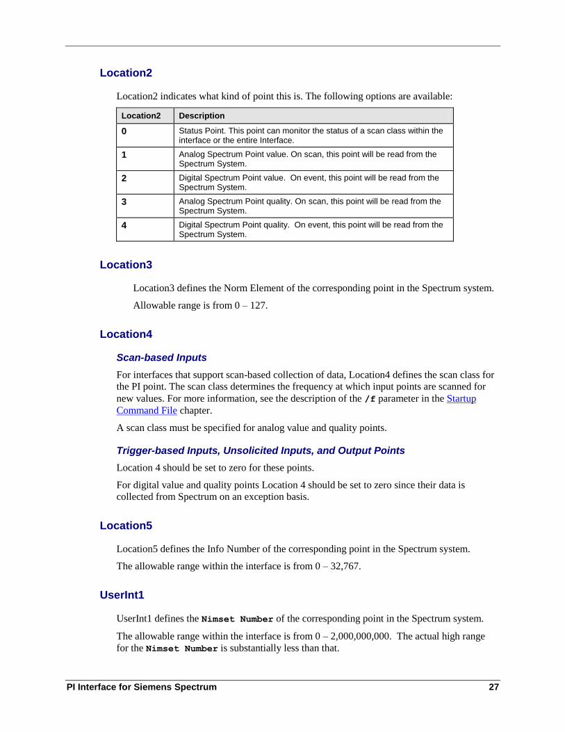
Location2
Location2 indicates what kind of point this is. The following options are available:
Location2 Description
0 Status Point. This point can monitor the status of a scan class within the interface or the entire Interface.
1 Analog Spectrum Point value. On scan, this point will be read from the Spectrum System.
2 Digital Spectrum Point value. On event, this point will be read from the Spectrum System.
3 Analog Spectrum Point quality. On scan, this point will be read from the Spectrum System.
4 Digital Spectrum Point quality. On event, this point will be read from the Spectrum System.
Location3
Location3 defines the Norm Element of the corresponding point in the Spectrum system.
Allowable range is from 0 – 127.
Location4
Scan-based Inputs
For interfaces that support scan-based collection of data, Location4 defines the scan class for
the PI point. The scan class determines the frequency at which input points are scanned for
new values. For more information, see the description of the /f parameter in the Startup
Command File chapter.
A scan class must be specified for analog value and quality points.
Trigger-based Inputs, Unsolicited Inputs, and Output Points
Location 4 should be set to zero for these points.
For digital value and quality points Location 4 should be set to zero since their data is
collected from Spectrum on an exception basis.
Location5
Location5 defines the Info Number of the corresponding point in the Spectrum system.
The allowable range within the interface is from 0 – 32,767.
UserInt1
UserInt1 defines the Nimset Number of the corresponding point in the Spectrum system.
The allowable range within the interface is from 0 – 2,000,000,000. The actual high range
for the Nimset Number is substantially less than that.
PI Point Configuration
28
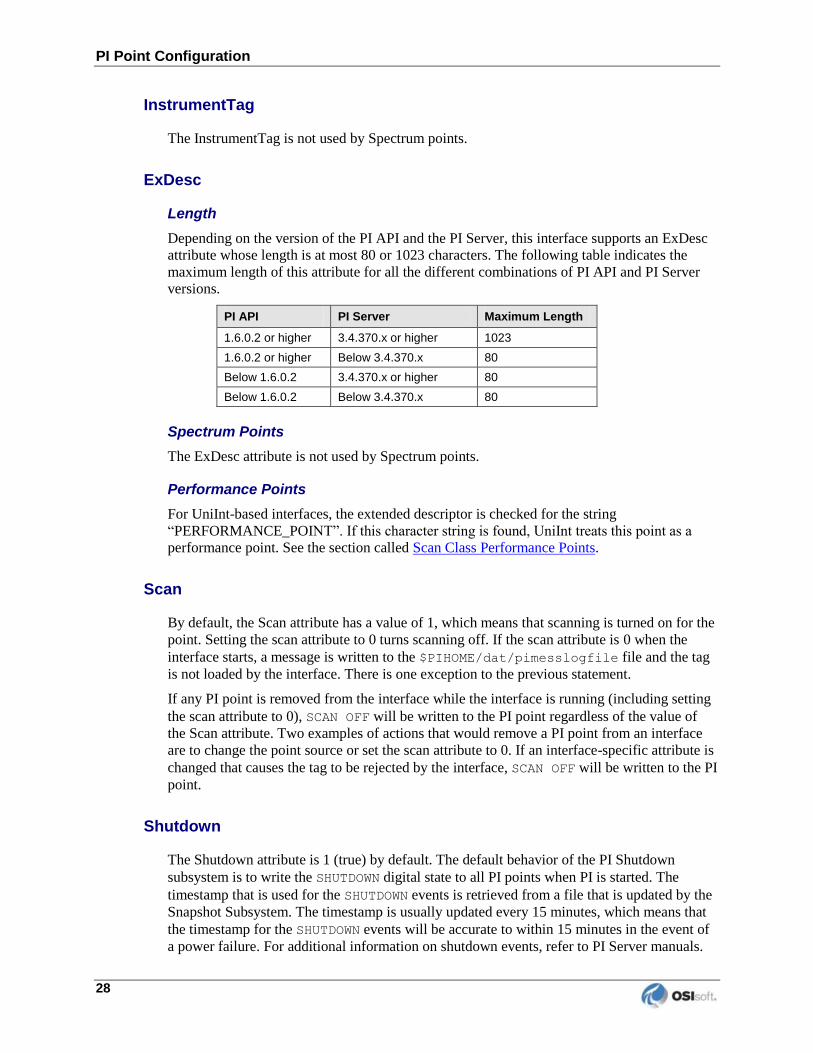
InstrumentTag
The InstrumentTag is not used by Spectrum points.
ExDesc
Length
Depending on the version of the PI API and the PI Server, this interface supports an ExDesc
attribute whose length is at most 80 or 1023 characters. The following table indicates the
maximum length of this attribute for all the different combinations of PI API and PI Server
versions.
PI API PI Server Maximum Length
1.6.0.2 or higher 3.4.370.x or higher 1023
1.6.0.2 or higher Below 3.4.370.x 80
Below 1.6.0.2 3.4.370.x or higher 80
Below 1.6.0.2 Below 3.4.370.x 80
Spectrum Points
The ExDesc attribute is not used by Spectrum points.
Performance Points
For UniInt-based interfaces, the extended descriptor is checked for the string
“PERFORMANCE_POINT”. If this character string is found, UniInt treats this point as a
performance point. See the section called Scan Class Performance Points.
Scan
By default, the Scan attribute has a value of 1, which means that scanning is turned on for the
point. Setting the scan attribute to 0 turns scanning off. If the scan attribute is 0 when the
interface starts, a message is written to the $PIHOME/dat/pimesslogfile file and the tag
is not loaded by the interface. There is one exception to the previous statement.
If any PI point is removed from the interface while the interface is running (including setting
the scan attribute to 0), SCAN OFF will be written to the PI point regardless of the value of
the Scan attribute. Two examples of actions that would remove a PI point from an interface
are to change the point source or set the scan attribute to 0. If an interface-specific attribute is
changed that causes the tag to be rejected by the interface, SCAN OFF will be written to the PI
point.
Shutdown
The Shutdown attribute is 1 (true) by default. The default behavior of the PI Shutdown
subsystem is to write the SHUTDOWN digital state to all PI points when PI is started. The
timestamp that is used for the SHUTDOWN events is retrieved from a file that is updated by the
Snapshot Subsystem. The timestamp is usually updated every 15 minutes, which means that
the timestamp for the SHUTDOWN events will be accurate to within 15 minutes in the event of
a power failure. For additional information on shutdown events, refer to PI Server manuals.
PI Interface for Siemens Spectrum 29
Note: The SHUTDOWN events that are written by the PI Shutdown subsystem are
independent of the SHUTDOWN events that are written by the interface when
the /stopstat=Shutdown command-line parameter is specified.
SHUTDOWN events can be disabled from being written to PI when PI is restarted by setting the
Shutdown attribute to 0 for each point. Alternatively, the default behavior of the PI Shutdown
Subsystem can be changed to write SHUTDOWN events only for PI points that have their
Shutdown attribute set to 0. To change the default behavior, edit the
\PI\dat\Shutdown.dat file, as discussed in PI Server manuals.
Bufserv
It is undesirable to write shutdown events when buffering is being used. Bufserv is a utility
program that provides the capability to store and forward events to a PI Server, allowing
continuous data collection when the PI Server is down for maintenance, upgrades, backups,
and unexpected failures. That is, when the PI Server is shutdown, Bufserv will continue to
collect data for the interface, making it undesirable to write SHUTDOWN events to the PI points
for this interface. Disabling Shutdown is recommended when sending data to a Highly
Available PI Server Collective. Refer to the Bufserv manual for additional information.

PI Interface for Siemens Spectrum 31
Chapter 8. Startup Command File
Command-line parameters can begin with a / or with a -. For example, the /ps=M and
-ps=M command-line parameters are equivalent.
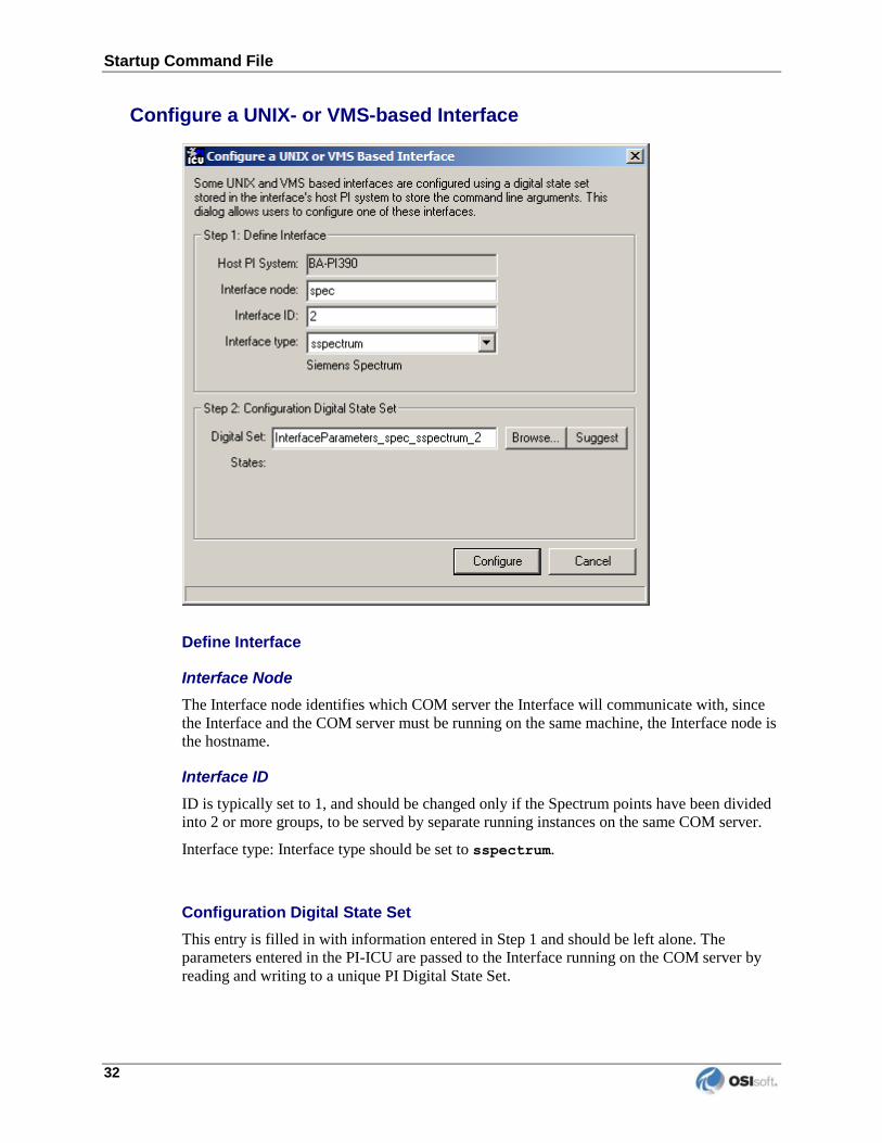
Configuring the Interface with PI ICU
Note: PI ICU requires PI 3.3 or greater.
The PI Interface Configuration Utility provides a graphical user interface for configuring
PI interfaces. The parameters are written by the ICU to a unique Digital State set that the
Interface then reads on startup. The name of the Digital State set is
InterfaceParameters_<API_Node_name>_sspectrum_#.
Note: If installing multiple PI-API installations, the number is the interface instance for that particular installation of the PI-API. e.g. For sspec_pi2_1, the name of the
Digital State set will be:
InterfaceParameters_<API_Node_name>_sspectrum_1.
The contents of this state set have each of the parameters written as separate entries.
When the Interface is started, once the connection to PI is made, this State set is read and
the Interface may begin sending data back to PI.
Under the Interface menu, select New Unix/VMS Interface to start configuring the first
instance of the Interface. In a hot failover environment, once this is done, select New
Unix/VMS Interface again to configure the second instance. Typically the two should
have almost identical set of parameters except the second instance will be identified as
running on a different Interface node. The spectrum control for PI-ICU has 7 sections.
Startup Command File
32
Configure a UNIX- or VMS-based Interface
Define Interface
Interface Node
The Interface node identifies which COM server the Interface will communicate with, since
the Interface and the COM server must be running on the same machine, the Interface node is
the hostname.
Interface ID
ID is typically set to 1, and should be changed only if the Spectrum points have been divided
into 2 or more groups, to be served by separate running instances on the same COM server.
Interface type: Interface type should be set to sspectrum.
Configuration Digital State Set
This entry is filled in with information entered in Step 1 and should be left alone. The
parameters entered in the PI-ICU are passed to the Interface running on the COM server by
reading and writing to a unique PI Digital State Set.
PI Interface for Siemens Spectrum 33
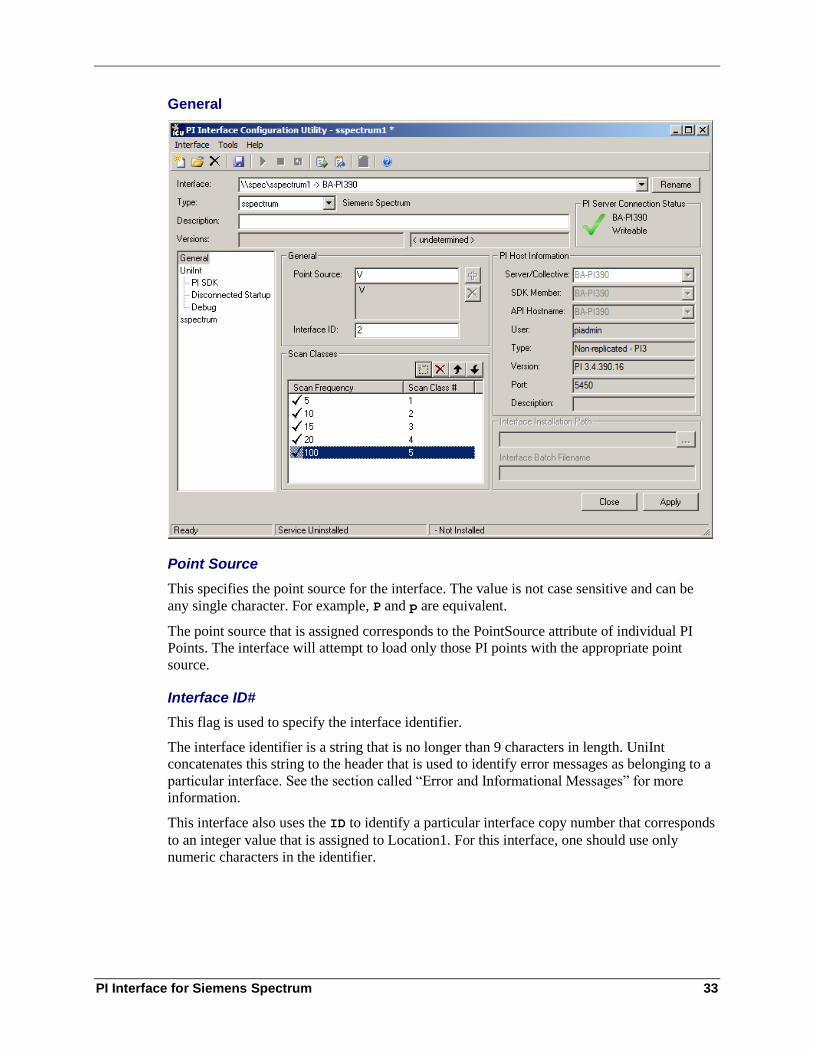
General
Point Source
This specifies the point source for the interface. The value is not case sensitive and can be
any single character. For example, P and p are equivalent.
The point source that is assigned corresponds to the PointSource attribute of individual PI
Points. The interface will attempt to load only those PI points with the appropriate point
source.
Interface ID#
This flag is used to specify the interface identifier.
The interface identifier is a string that is no longer than 9 characters in length. UniInt
concatenates this string to the header that is used to identify error messages as belonging to a
particular interface. See the section called “Error and Informational Messages” for more
information.
This interface also uses the ID to identify a particular interface copy number that corresponds
to an integer value that is assigned to Location1. For this interface, one should use only
numeric characters in the identifier.
Startup Command File
34
PI Host Information
Host
This is the name of the PI server this Interface will be communicating with. This should be
the same as specified in the piclient.ini file on the Interface node.
Scan Classes
Scan Class
Possible formats: SS or SS,SS or HH:MM:SS or HH:MM:SS,hh:mm:ss
The scan class attribute defines the time period between scans in terms of hours (HH), minutes
(MM), and seconds (SS). The scans can be scheduled to occur at discrete moments in time with
an optional time offset specified in terms of hours (hh), minutes (mm), and seconds (ss). If HH
and MM are omitted, then the time period that is specified is assumed to be in seconds.
Each instance defines a scan class for the interface. There is no limit to the number of scan
classes that can be defined. The first occurrence defines the first scan class of the interface,
the second occurrence defines the second scan class, and so on. PI Points are associated with
a particular scan class via the Location4 PI Point attribute. For example, all PI Points that
have Location4 set to 1 will receive input values at the frequency defined by the first scan
class. Similarly, all points that have Location4 set to 2 will receive input values at the
frequency specified by the second scan class, and so on.
Two scan classes are defined in the following example: 00:01:00,00:00:05 and 00:00:07
or, equivalently: 60,5 and 7
The first scan class has a scanning frequency of 1 minute with an offset of 5 seconds, and the
second scan class has a scanning frequency of 7 seconds. When an offset is specified, the
scans occur at discrete moments in time according to the formula:
scan times = (reference time) + n(frequency) + offset
where n is an integer and the reference time is midnight on the day that the interface was
started. In the above example, frequency is 60 seconds and offset is 5 seconds for the first
scan class. This means that if the interface was started at 05:06:06, the first scan would be at
05:06:10, the second scan would be at 05:07:10, and so on. Since no offset is specified for the
second scan class, the absolute scan times are undefined.
The definition of a scan class does not guarantee that the associated points will be scanned at
the given frequency. If the interface is under a large load, then some scans may occur late or
be skipped entirely. See the section called “Performance Point Configuration” for more
information on skipped or missed scans.
Wall Clock Scheduling
Scan classes that strictly adhere to wall clock scheduling are now possible. This feature is
available for interfaces that run on NT and/or UNIX. Previously, wall clock scheduling was
possible, but not across daylight savings time. For example, /f=24:00:00,08:00:00
corresponds to 1 scan a day starting at 8 AM. However, after a Daylight Savings Time
change, the scan would occur either at 7 AM or 9 AM, depending upon the direction of the
time shift. To schedule a scan once a day at 8 AM (even across daylight savings time), one
should use /f=24:00:00,00:08:00,L. The ,L at the end of the scan class tells UniInt to use the
new wall clock scheduling algorithm.New values for Analog Spectrum points are polled from
PI Interface for Siemens Spectrum 35
the Spectrum system at regular scanning frequencies. The Location4 attribute of the point
determines which scan class the point belongs to and the frequency in which it’s read.
For more information see the section below labeled “Scan Class Configuration.”
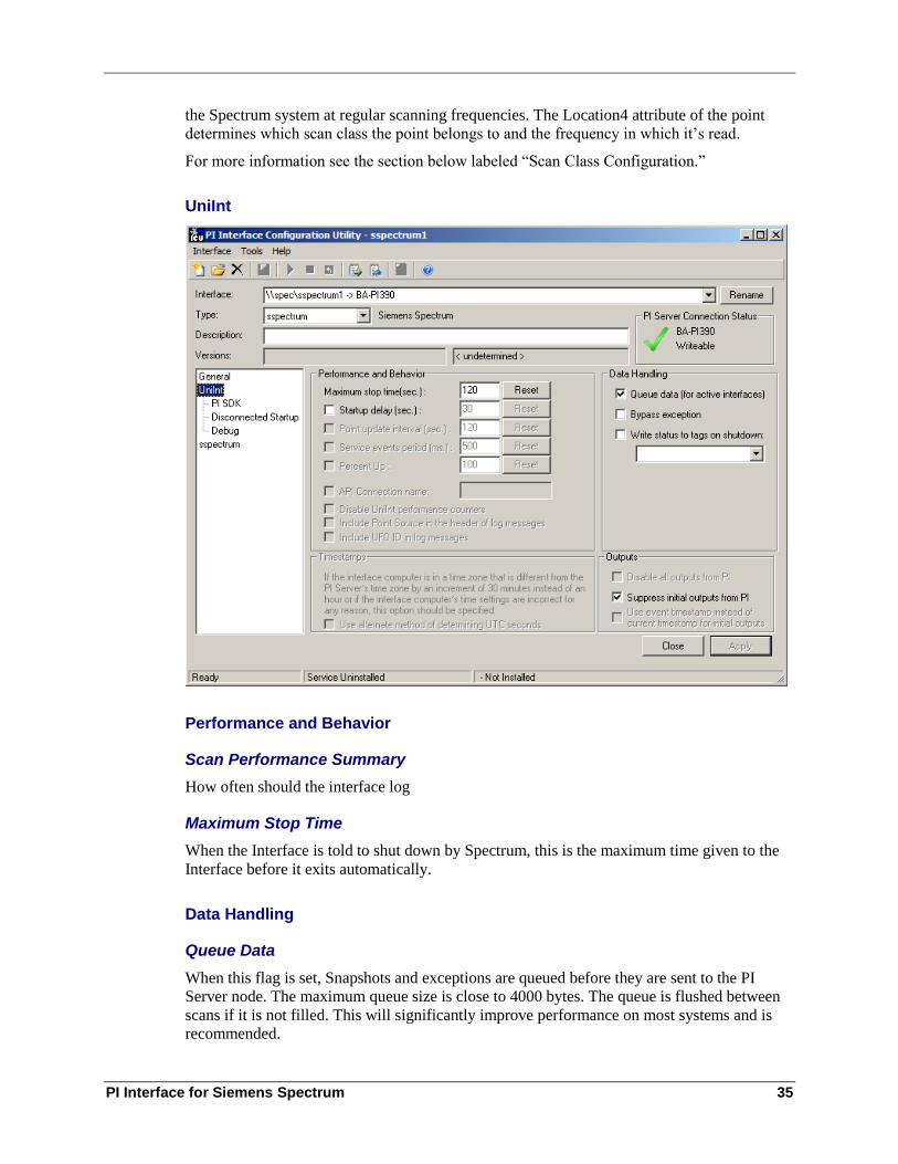
UniInt
Performance and Behavior
Scan Performance Summary
How often should the interface log
Maximum Stop Time
When the Interface is told to shut down by Spectrum, this is the maximum time given to the
Interface before it exits automatically.
Data Handling
Queue Data
When this flag is set, Snapshots and exceptions are queued before they are sent to the PI
Server node. The maximum queue size is close to 4000 bytes. The queue is flushed between
scans if it is not filled. This will significantly improve performance on most systems and is
recommended.
Startup Command File
36
Write Status to Tags on Shutdown
This should be specified if the Spectrum system contains only one COM server. The
interface will write INTF SHUT to its points if the interface shuts down.
This parameter should NOT be specified if the Spectrum system contains two COM servers
that are configured in a failover architecture, since the /pish flag should then be specified in
the next section.
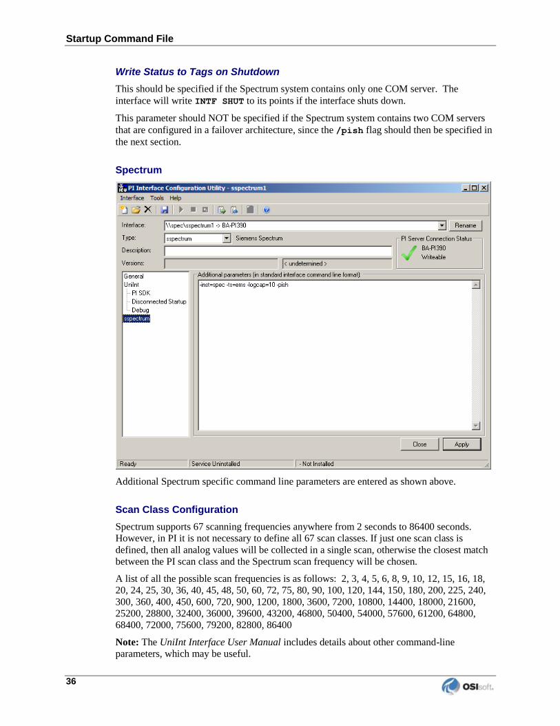
Spectrum
Additional Spectrum specific command line parameters are entered as shown above.
Scan Class Configuration
Spectrum supports 67 scanning frequencies anywhere from 2 seconds to 86400 seconds.
However, in PI it is not necessary to define all 67 scan classes. If just one scan class is
defined, then all analog values will be collected in a single scan, otherwise the closest match
between the PI scan class and the Spectrum scan frequency will be chosen.
A list of all the possible scan frequencies is as follows: 2, 3, 4, 5, 6, 8, 9, 10, 12, 15, 16, 18,
20, 24, 25, 30, 36, 40, 45, 48, 50, 60, 72, 75, 80, 90, 100, 120, 144, 150, 180, 200, 225, 240,
300, 360, 400, 450, 600, 720, 900, 1200, 1800, 3600, 7200, 10800, 14400, 18000, 21600,
25200, 28800, 32400, 36000, 39600, 43200, 46800, 50400, 54000, 57600, 61200, 64800,
68400, 72000, 75600, 79200, 82800, 86400
Note: The UniInt Interface User Manual includes details about other command-line
parameters, which may be useful.
PI Interface for Siemens Spectrum 37
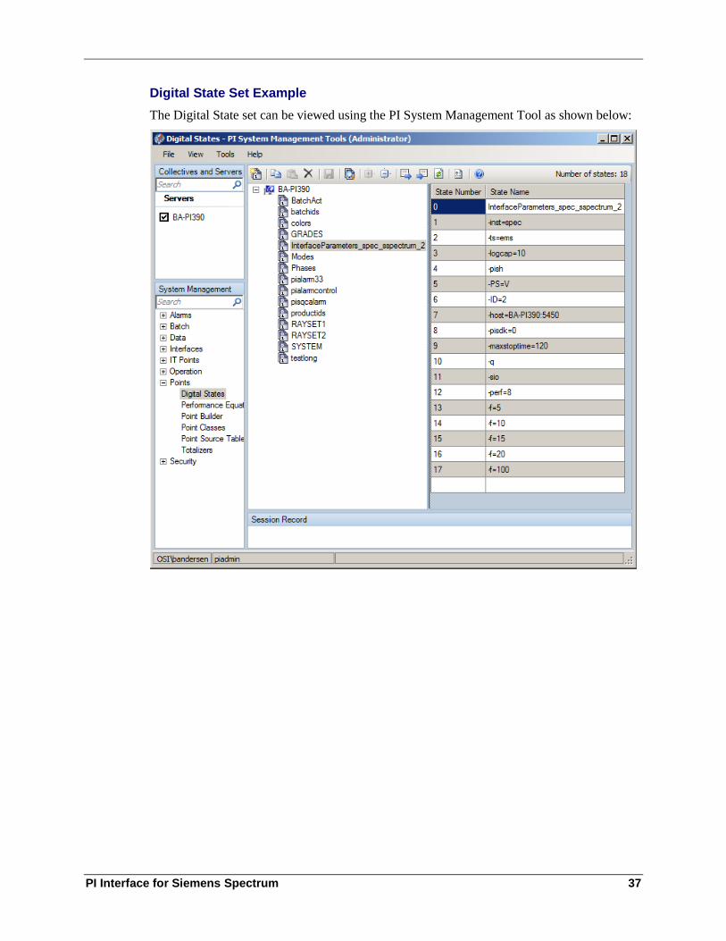
Digital State Set Example
The Digital State set can be viewed using the PI System Management Tool as shown below:
Startup Command File
38
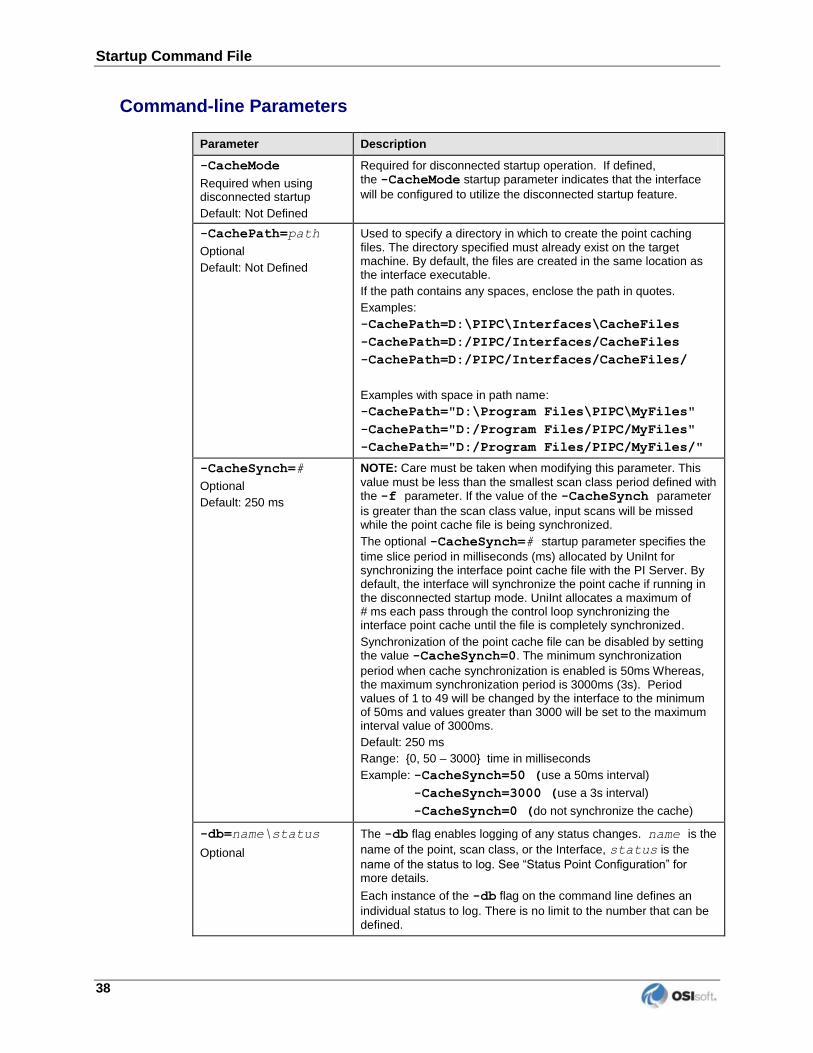
Command-line Parameters
Parameter Description
-CacheMode
Required when using disconnected startup
Default: Not Defined
Required for disconnected startup operation. If defined, the -CacheMode startup parameter indicates that the interface
will be configured to utilize the disconnected startup feature.
-CachePath=path
Optional
Default: Not Defined
Used to specify a directory in which to create the point caching files. The directory specified must already exist on the target machine. By default, the files are created in the same location as the interface executable.
If the path contains any spaces, enclose the path in quotes.
Examples:
-CachePath=D:\PIPC\Interfaces\CacheFiles
-CachePath=D:/PIPC/Interfaces/CacheFiles
-CachePath=D:/PIPC/Interfaces/CacheFiles/
Examples with space in path name:
-CachePath="D:\Program Files\PIPC\MyFiles"
-CachePath="D:/Program Files/PIPC/MyFiles"
-CachePath="D:/Program Files/PIPC/MyFiles/"
-CacheSynch=#
Optional
Default: 250 ms
NOTE: Care must be taken when modifying this parameter. This
value must be less than the smallest scan class period defined with the -f parameter. If the value of the -CacheSynch parameter
is greater than the scan class value, input scans will be missed while the point cache file is being synchronized.
The optional -CacheSynch=# startup parameter specifies the
time slice period in milliseconds (ms) allocated by UniInt for synchronizing the interface point cache file with the PI Server. By default, the interface will synchronize the point cache if running in the disconnected startup mode. UniInt allocates a maximum of # ms each pass through the control loop synchronizing the interface point cache until the file is completely synchronized.
Synchronization of the point cache file can be disabled by setting the value -CacheSynch=0. The minimum synchronization
period when cache synchronization is enabled is 50ms Whereas, the maximum synchronization period is 3000ms (3s). Period values of 1 to 49 will be changed by the interface to the minimum of 50ms and values greater than 3000 will be set to the maximum interval value of 3000ms.
Default: 250 ms
Range: {0, 50 – 3000} time in milliseconds
Example: -CacheSynch=50 (use a 50ms interval)
-CacheSynch=3000 (use a 3s interval)
-CacheSynch=0 (do not synchronize the cache)
-db=name\status
Optional
The -db flag enables logging of any status changes. name is the
name of the point, scan class, or the Interface, status is the
name of the status to log. See “Status Point Configuration” for more details.
Each instance of the -db flag on the command line defines an
individual status to log. There is no limit to the number that can be defined.
PI Interface for Siemens Spectrum 39
Parameter Description
-dor_info
Optional
The -dor_info flag defines the Info Element portion of the
DOR Spectrum digital.
-dor_nimset
Optional
The -dor_nimset flag defines the Nimset Element portion of
the Spectrum digital.
-dor_noel
Optional
The -dor_noel flag is part of a set of four flags that should be
set together (all starting with “dor_”) that provide a way for the interface to determine at runtime whether it is talking to the “Data of Record” system. This is done by periodically reading a specific Spectrum digital value (defined by Norm Element, Info, and Nimset), and comparing it with the specified Value). If the value matches, then the interface is talking to the system of record and data is sent to the PI server, otherwise data is not sent. The -dor_noel flag defines the Norm Element portion of this
Spectrum digital.
-dor_value
Optional
The -dor_value flag defines the Value of the Spectrum digital
which will determine whether it’s the DOR.
-dsa
Optional
This flag enables logging Spectrum API calls.
-ec=#
Optional
The first instance of the -ec parameter on the command-line is
used to specify a counter number, #, for an I/O Rate point. If the #
is not specified, then the default event counter is 1. Also, if the -ec
parameter is not specified at all, there is still a default event counter of 1 associated with the interface. If there is an I/O Rate point that is associated with an event counter of 1, every interface that is running without -ec=# explicitly defined will write to the
same I/O Rate point. Either explicitly define an event counter other than 1 for each instance of the interface or do not associate any I/O Rate points with event counter 1. Configuration of I/O Rate points is discussed in the section called I/O Rate Point.
-f=SS.##
or
-f=SS.##,ss.##
or
-f=HH:MM:SS.##
or
-f=HH:MM:SS.##,
hh:mm:ss.##
Required for reading scan-based inputs
The -f parameter defines the time period between scans in terms
of hours (HH), minutes (MM), seconds (SS) and sub-seconds (##).
The scans can be scheduled to occur at discrete moments in time
with an optional time offset specified in terms of hours (hh),
minutes (mm), seconds (ss), and sub-seconds (##). If HH and MM
are omitted, then the time period that is specified is assumed to be in seconds.
Each instance of the -f parameter on the command-line defines a
scan class for the interface. There is no limit to the number of scan classes that can be defined. The first occurrence of the -f
parameter on the command-line defines the first scan class of the interface; the second occurrence defines the second scan class, and so on. PI Points are associated with a particular scan class via the Location4 PI Point attribute. For example, all PI Points that have Location4 set to 1 will receive input values at the frequency defined by the first scan class. Similarly, all points that have Location4 set to 2 will receive input values at the frequency specified by the second scan class, and so on.
Two scan classes are defined in the following example:
-f=00:01:00,00:00:05 -f=00:00:07
or, equivalently:
-f=60,5 -f=7
Startup Command File
40
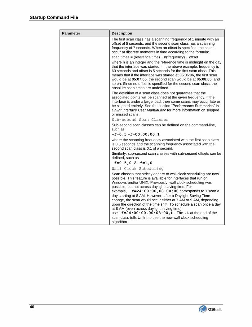
Parameter Description
The first scan class has a scanning frequency of 1 minute with an offset of 5 seconds, and the second scan class has a scanning frequency of 7 seconds. When an offset is specified, the scans occur at discrete moments in time according to the formula:
scan times = (reference time) + n(frequency) + offset
where n is an integer and the reference time is midnight on the day that the interface was started. In the above example, frequency is 60 seconds and offset is 5 seconds for the first scan class. This means that if the interface was started at 05:06:06, the first scan would be at 05:07:05, the second scan would be at 05:08:05, and
so on. Since no offset is specified for the second scan class, the absolute scan times are undefined.
The definition of a scan class does not guarantee that the associated points will be scanned at the given frequency. If the interface is under a large load, then some scans may occur late or be skipped entirely. See the section “Performance Summaries” in UniInt Interface User Manual.doc for more information on skipped or missed scans.
Sub-second Scan Classes
Sub-second scan classes can be defined on the command-line, such as
-f=0.5 -f=00:00:00.1
where the scanning frequency associated with the first scan class is 0.5 seconds and the scanning frequency associated with the second scan class is 0.1 of a second.
Similarly, sub-second scan classes with sub-second offsets can be defined, such as
-f=0.5,0.2 -f=1,0
Wall Clock Scheduling
Scan classes that strictly adhere to wall clock scheduling are now possible. This feature is available for interfaces that run on Windows and/or UNIX. Previously, wall clock scheduling was possible, but not across daylight saving time. For example, -f=24:00:00,08:00:00 corresponds to 1 scan a
day starting at 8 AM. However, after a Daylight Saving Time change, the scan would occur either at 7 AM or 9 AM, depending upon the direction of the time shift. To schedule a scan once a day at 8 AM (even across daylight saving time), use -f=24:00:00,00:08:00,L. The ,L at the end of the
scan class tells UniInt to use the new wall clock scheduling algorithm.
PI Interface for Siemens Spectrum 41
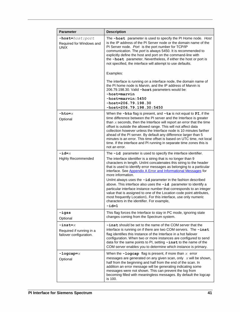
Parameter Description
-host=host:port
Required for Windows and UNIX
The -host parameter is used to specify the PI Home node. Host
is the IP address of the PI Server node or the domain name of the PI Server node. Port is the port number for TCP/IP communication. The port is always 5450. It is recommended to
explicitly define the host and port on the command-line with the -host parameter. Nevertheless, if either the host or port is
not specified, the interface will attempt to use defaults.
Examples: The interface is running on a interface node, the domain name of the PI home node is Marvin, and the IP address of Marvin is 206.79.198.30. Valid -host parameters would be:
-host=marvin
-host=marvin:5450
-host=206.79.198.30
-host=206.79.198.30:5450
-hto=x
Optional
When the -hto flag is present, and -ts is not equal to PI, if the
time difference between the PI server and the Interface is greater
than x seconds, then the Interface will report an error that the time
offset is outside the allowed range. This will not affect data collection however unless the Interface node is 10 minutes farther ahead of the PI server. By default any difference larger than 5 minutes is an error. This time offset is based on UTC time, not local time. If the interface and PI running in separate time zones this is not an error.
-id=x
Highly Recommended
The -id parameter is used to specify the interface identifier.
The interface identifier is a string that is no longer than 9 characters in length. UniInt concatenates this string to the header that is used to identify error messages as belonging to a particular interface. See Appendix A Error and Informational Messages for more information.
UniInt always uses the -id parameter in the fashion described
above. This interface also uses the -id parameter to identify a
particular interface instance number that corresponds to an integer value that is assigned to one of the Location code point attributes, most frequently Location1. For this interface, use only numeric characters in the identifier. For example,
-id=1
-igss
Optional
This flag forces the Interface to stay in PC mode, ignoring state changes coming from the Spectrum system.
-inst=x
Required if running in a failover configuration.
-inst should be set to the name of the COM server that the
interface is running on if there are two COM servers. The -inst
flag identifies this Instance of the Interface in a hot failover configuration. When two or more instances are configured to send data for the same points to PI, setting -inst to the name of the
COM server enables you to determine which instance is primary.
-logcap=x
Optional
When the -logcap flag is present, if more than x error
messages are generated on any given scan, only x will be shown,
half from the beginning and half from the end of the scan. In addition an error message will be generating indicating some messages were not shown. This can prevent the log from becoming filled with meaningless messages. By default the logcap is 100.
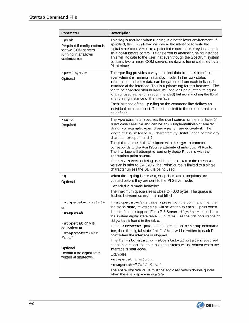
Startup Command File
42
Parameter Description
-pish
Required if configuration is for two COM servers running in a failover configuration
This flag is required when running in a hot failover environment. If specified, the -pish flag will cause the interface to write the
digital state INTF SHUT to a point if the current primary instance is shut down before control is transferred to another running instance. This will indicate to the user that even though the Spectrum system contains two or more COM servers, no data is being collected by a PI interface.
-pr=tagname
Optional
The -pr flag provides a way to collect data from this Interface
even when it is running in standby mode. In this way status information and other data can be gathered from each individual instance of the interface. This is a private tag for this instance. The tag to be collected should have its Location1 point attribute equal to an unused value (0 is recommended) but not matching the ID of any running instance of the interface.
Each instance of the -pr flag on the command line defines an
individual point to collect. There is no limit to the number that can be defined.
-ps=x
Required
The -ps parameter specifies the point source for the interface. X
is not case sensitive and can be any <single/multiple> character string. For example, -ps=P and -ps=p are equivalent. The
length of X is limited to 100 characters by UniInt. X can contain any
character except ‘*’ and ‘?’.
The point source that is assigned with the -ps parameter
corresponds to the PointSource attribute of individual PI Points. The interface will attempt to load only those PI points with the appropriate point source.
If the PI API version being used is prior to 1.6.x or the PI Server version is prior to 3.4.370.x, the PointSource is limited to a single character unless the SDK is being used.
-q
Optional
When the -q flag is present, Snapshots and exceptions are
queued before they are sent to the PI Server node.
Extended API mode behavior:
The maximum queue size is close to 4000 bytes. The queue is flushed between scans if it is not filled.
-stopstat=digstate
or
-stopstat
-stopstat only is
equivalent to
-stopstat="Intf
Shut"
Optional
Default = no digital state written at shutdown.
If -stopstat=digstate is present on the command line, then
the digital state, digstate, will be written to each PI point when
the interface is stopped. For a PI3 Server, digstate must be in
the system digital state table. . UniInt will use the first occurrence of
digstate found in the table.
If the -stopstat parameter is present on the startup command
line, then the digital state Intf Shut will be written to each PI
point when the interface is stopped.
If neither -stopstat nor -stopstat=digstate is specified
on the command line, then no digital states will be written when the interface is shut down.
Examples:
-stopstat=shutdown
-stopstat="Intf Shut"
The entire digstate value must be enclosed within double quotes when there is a space in digstate.

PI Interface for Siemens Spectrum 43
Parameter Description
-ts=EMS
or
-ts=PI
Optional
If -ts=EMS is present on the command line, then all points, both
analog and digital will be time stamped using the Spectrum EMS time, which is passed along with the data by Spectrum.
If -ts=PI is present on the command line, then all points, both
analog and digital will be time stamped using PI time.
The default, (i.e. no -ts option present on the command line) is to
time stamp data to that of Spectrum, with analog points being stamped with the time the scan occurred and digitals being stamped based on the time passed by Spectrum.


PI Interface for Siemens Spectrum 45
Chapter 9. Interface Node Clock
The correct time and time zone must be configured on the interface node. Also, the interface
node should be configured to automatically adjust for daylight saving time for locations that
use daylight saving time. The correct local settings should be used even if the interface node
runs in a different time zone than the PI Server node.

PI Interface for Siemens Spectrum 47
Chapter 10. Security
UNIX
The PI Firewall Database and the PI Proxy Database must be configured so that the interface
is allowed to write data to the PI Server. See “Modifying the Firewall Database” and
“Modifying the Proxy Database” in the PI Server manuals.
Note that the Trust Database, which is maintained by the Base Subsystem, replaces the Proxy
Database used prior to PI version 3.3. The Trust Database maintains all the functionality of
the proxy mechanism while being more secure.
See “Trust Login Security” in the chapter “Managing Security” of the PI Server System
Management Guide.
If the interface cannot write data to the PI Server because it has insufficient privileges,
a -10401 error will be reported in the $PIHOME/dat/pimesslogfile file. If the interface
cannot send data to a PI2 Server, it writes a -999 error. See the section Appendix A: Error and
Informational Messages for additional information on error messaging.
PI Server v3.3 and Higher
Security configuration using piconfig
For PI Server v3.3 and higher, the following example demonstrates how to edit the PI Trust
table:
C:\PI\adm> piconfig
@table pitrust
@mode create
@istr Trust,IPAddr,NetMask,PIUser
a_trust_name,192.168.100.11,255.255.255.255,piadmin
@quit
For the above,
Trust: An arbitrary name for the trust table entry; in the above example,
a_trust_name
IPAddr: the IP Address of the computer running the interface; in the above example,
192.168.100.11
NetMask: the network mask; 255.255.255.255 specifies an exact match with IPAddr
PIUser: the PI user the interface to be entrusted as; piadmin is usually an appropriate user
Security
48
Security Configuring using Trust Editor
The Trust Editor plug-in for PI System Management Tools 3.x may also be used to edit the PI
Trust table.
See the PI System Management chapter in the PI Server manual for more details on security
configuration.
PI Server v3.2
For PI Server v3.2, the following example demonstrates how to edit the PI Proxy table:
C:\PI\adm> piconfig
@table pi_gen,piproxy
@mode create
@istr host,proxyaccount
piapimachine,piadmin
@quit
In place of piapimachine, put the name of the interface node as it is seen by the PI Server.

PI Interface for Siemens Spectrum 49
Chapter 11. Starting / Stopping the Interface on UNIX
The PI-API processes must be started before the Interface can run. See the PI-API Installation
Instructions on how to set the API to run automatically when the server starts up.
Once the Interface is built, and installed, the Interface will start and stop as a standard
Spectrum program. This means that it will come up automatically as a Spectrum program,
respond to the Initial Softinit signal, and shut down when an Endprog signal is received.

PI Interface for Siemens Spectrum 51
Chapter 12. Buffering
Buffering refers to an interface node’s ability to temporarily store the data that interfaces
collect and to forward these data to the appropriate PI Servers. OSIsoft strongly recommends
that you enable buffering on your interface nodes. Otherwise, if the interface node stops
communicating with the PI Server, you lose the data that your interfaces collect.
On UNIX systems, the PI API Buffer Server (Bufserv) is the buffering system available.
If you have PI Servers that are part of a PI collective, Bufserv supports n-way buffering. N-
way buffering refers to the ability of a buffering application to send the same data to each of
the PI Servers in a PI collective.
How Buffering Works
A complete technical description of Bufserv is beyond the scope of this document. However,
the following paragraphs provide some insights on how buffering works.
When an interface node has buffering enabled, the Bufserv connects to the PI Server. It also
creates shared memory storage.
When an interface program makes a PI API function call that writes data to the PI Server (for
example, pisn_sendexceptionqx()), the PI API checks whether buffering is enabled. If it
is, these data writing functions do not send the interface data to the PI Server. Instead, they
write the data to the shared memory storage that the buffering application created.
Bufserv in turn
reads the data in shared memory, and
if a connection to the PI Server exists, sends the data to the PI Server; or
if there is no connection to the PI Server, continues to store the data in shared
memory (if shared memory storage is available) or writes the data to disk (if shared
memory storage is full).
When the buffering application re-establishes connection to the PI Server, it writes to the PI
Server the interface data contained in both shared memory storage and disk.
When Bufserv writes interface data to disk, it writes to a single file. The name of its buffering
file is APIBUF.DAT.
As a previous paragraph indicates, Bufserv creates shared memory storage at startup. These
memory buffers must be large enough to accommodate the data that an interface collects
during a single scan. Otherwise, the interface may fail to write all its collected data to the
memory buffers, resulting in data loss. The buffering configuration section of this chapter
provides guidelines for sizing these memory buffers.
Buffering
52
When buffering is enabled, it affects the entire interface node. That is, you do not have a
scenario whereby the buffering application buffers data for one interface running on an
interface node but not for another interface running on the same interface node.
Buffering and PI Server Security
After you enable buffering, it is the buffering application – and not the interface program –
that writes data to the PI Server. If the PI Server’s trust table contains a trust entry that
allows all applications on an interface node to write data, then the buffering application is
able write data to the PI Server.
However, if the PI Server contains an interface-specific PI Trust entry that allows a particular
interface program to write data, you must have a PI Trust entry specific to buffering. The
following are the appropriate entries for the Application Name field of a PI Trust entry:
Buffering Application Application Name field for PI Trust
PI API Buffer Server APIBE (if the PI API is using 4 character process names)
APIBUF (if the PI API is using 8 character process names)
To use a process name greater than 4 characters in length for a trust application name, use the
LONGAPPNAME=1 in the PIClient.ini file.
Configuring Buffering on an Interface Node
Buffering is enabled through the use of a configuration file, piclient.ini. Unless this file
is modified to explicitly enable buffering, the PI-API will not buffer data, sending data
directly to the home node.
There are no additional steps needed to install buffering after installing the PI-API. The
delivered PI-API library supports both buffered and un-buffered calls.
Note: When buffering is configured to be on, the bufserv process must be started
before other programs using the PI-API, so that these programs can access the shared buffering resources. Any program that makes a connection to a PI Server has this requirement even if it does not write to PI.
Configuration of buffering is achieved through entries in the piclient.ini file. The file is
found in the dat subdirectory of the PIHOME directory (typically c:\pipc\dat) under
Windows NT. On UNIX systems, the file is found in the dat subdirectory of the PIHOME
directory (e.g., /opt/piapi/dat). This file follows the conventions of Microsoft Windows
initialization files with sections, keywords within sections, and values for keywords. All
buffering settings are entered in a section called [APIBUFFER]. To modify settings, simply
edit the piclient.ini file in a text editor (Notepad on Windows, vi on UNIX) to the
desired values.
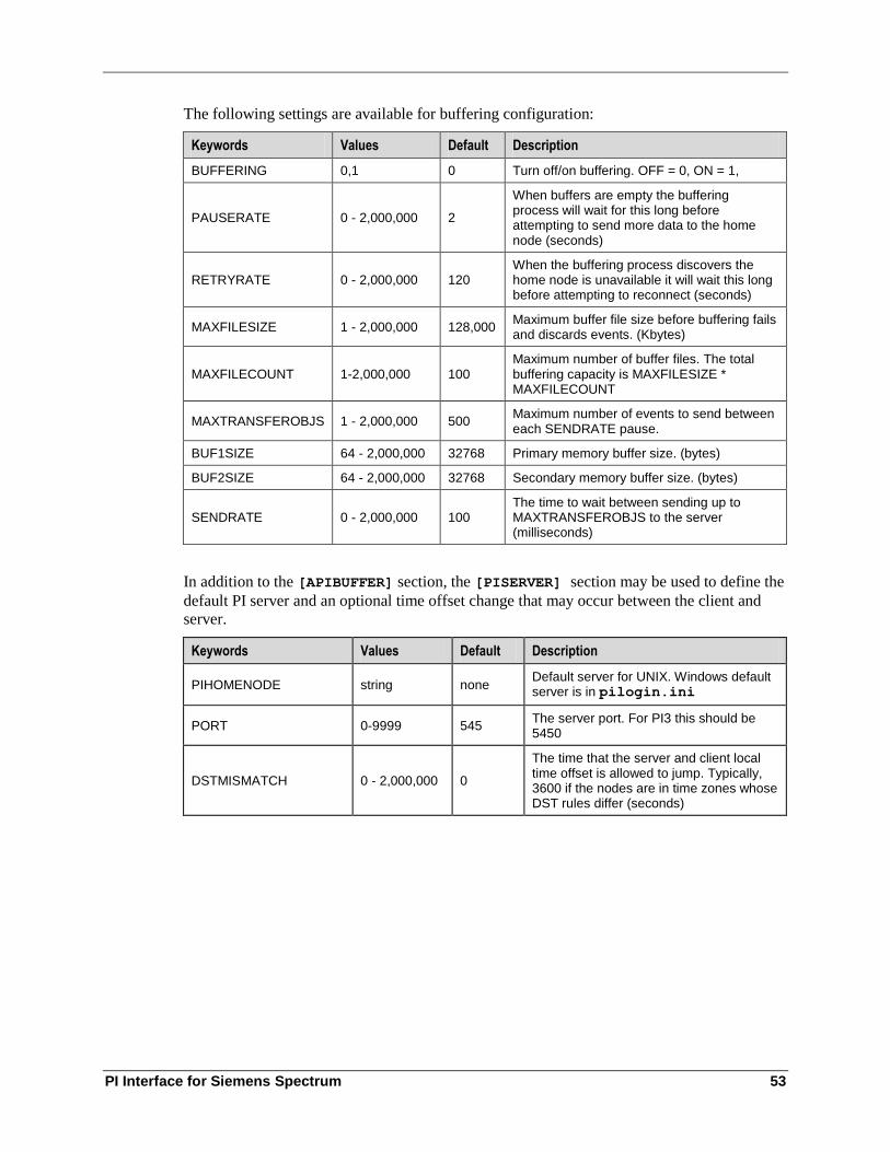
PI Interface for Siemens Spectrum 53
The following settings are available for buffering configuration:
Keywords Values Default Description
BUFFERING 0,1 0 Turn off/on buffering. OFF = 0, ON = 1,
PAUSERATE 0 - 2,000,000 2
When buffers are empty the buffering process will wait for this long before attempting to send more data to the home node (seconds)
RETRYRATE 0 - 2,000,000 120 When the buffering process discovers the home node is unavailable it will wait this long before attempting to reconnect (seconds)
MAXFILESIZE 1 - 2,000,000 128,000 Maximum buffer file size before buffering fails and discards events. (Kbytes)
MAXFILECOUNT 1-2,000,000 100 Maximum number of buffer files. The total buffering capacity is MAXFILESIZE * MAXFILECOUNT
MAXTRANSFEROBJS 1 - 2,000,000 500 Maximum number of events to send between each SENDRATE pause.
BUF1SIZE 64 - 2,000,000 32768 Primary memory buffer size. (bytes)
BUF2SIZE 64 - 2,000,000 32768 Secondary memory buffer size. (bytes)
SENDRATE 0 - 2,000,000 100 The time to wait between sending up to MAXTRANSFEROBJS to the server (milliseconds)
In addition to the [APIBUFFER] section, the [PISERVER] section may be used to define the
default PI server and an optional time offset change that may occur between the client and
server.
Keywords Values Default Description
PIHOMENODE string none Default server for UNIX. Windows default server is in pilogin.ini
PORT 0-9999 545 The server port. For PI3 this should be 5450
DSTMISMATCH 0 - 2,000,000 0
The time that the server and client local time offset is allowed to jump. Typically, 3600 if the nodes are in time zones whose DST rules differ (seconds)
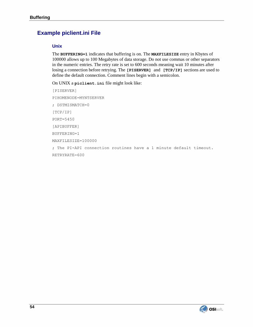
Buffering
54
Example piclient.ini File
Unix
The BUFFERING=1 indicates that buffering is on. The MAXFILESIZE entry in Kbytes of
100000 allows up to 100 Megabytes of data storage. Do not use commas or other separators
in the numeric entries. The retry rate is set to 600 seconds meaning wait 10 minutes after
losing a connection before retrying. The [PISERVER] and [TCP/IP] sections are used to
define the default connection. Comment lines begin with a semicolon.
On UNIX a piclient.ini file might look like:
[PISERVER]
PIHOMENODE=MYNTSERVER
; DSTMISMATCH=0
[TCP/IP]
PORT=5450
[APIBUFFER]
BUFFERING=1
MAXFILESIZE=100000
; The PI-API connection routines have a 1 minute default timeout.
RETRYRATE=600
PI Interface for Siemens Spectrum 55
Chapter 13. Interface Diagnostics Configuration
The PI Point Configuration chapter provides information on building PI points for collecting
data from the device. This chapter describes the configuration of points related to interface
diagnostics.
Configuring Performance Points on UNIX
Performance point configuration is the same on all operating system platforms. Performance
points are configured as follows.
1. Set the extended descriptor to:
PERFORMANCE_POINT
or to:
PERFORMANCE_POINT=interface_id
where interface_id corresponds to the identifier that is specified with the
/id parameter on the startup command-line of the interface. The character string
PERFORMANCE_POINT is case insensitive. The interface_id does not need to be
specified if there is only one copy of an interface that is associated with a particular
point source.
2. Set Location4 to correspond to the scan class whose performance is to be monitored.
For example, to monitor scan class 2, set Location4 to 2. See the /f parameter for a
description of scan classes.
3. Set the PointSource attribute to correspond to the /ps parameter on the startup
command-line of the interface.
4. Set the PointType attribute to float32.
Interface Diagnostics Configuration
56
Interface Health Monitoring Points
This interface does not support the Interface Health Monitoring Points.
I/O Rate Point
An I/O Rate point measures the rate at which the interface writes data to its input tags. The
value of an I/O Rate point represents a 10-minute average of the total number of values per
minute that the interface sends to the PI Server.
When the interface starts, it writes 0 to the I/O Rate point. After running for ten minutes, the
interface writes the I/O Rate value. The interface continues to write a value every 10 minutes.
When the interface stops, it writes 0.
Configuring I/O Rate Tags On UNIX
There are two configuration steps.
1. Configuring the PI Point on the PI Server
2. Configuration on the interface node
Configuring PI Point on the PI Server
Create an I/O Rate Tag with the following point attribute values.
Attribute Value
PointSource LAB
PointType float32
Compressing 0
ExcDev 0
Configuration on the Interface Node
For the following examples, assume that the name of the PI tag is SISpectrum001, and that
the name of the I/O Rate on the home node is SISpectrum001.
1. Edit/Create a file called iorates.dat in the $PIHOME/dat directory. PIHOME is an
environment variable that is set equal to the PI home directory name as discussed in
the PI API manual.
Add a line in the iorates.dat file of the form:
SISpectrum001, x
where SISpectrum001is the name of the I/O Rate Tag and x corresponds to the
first instance of the /ec=x parameter in the startup command file. X can be any
number between 1 and 34 or between 51 and 200, inclusive. However, it is best to
use an event counter, x, that is not equal to 1 because 1 is the default event counter
for UniInt-based interfaces.
PI Interface for Siemens Spectrum 57
To specify additional rate counters for additional copies of the interface, create
additional I/O Rate tags and additional entries in the iorates.dat file. The event
counter, /ec=x, should be unique for each copy of the interface.
2. Set the /ec=x parameter on the startup command file of the interface to match the
event counter in the iorates.dat file.
3. The I/O Rate shared memory server and the I/O Rate monitor program must be
stopped and started for the changes to take effect. The easiest way to do this is to run
the pistop and pistart command scripts with the following commands:
sh $PIHOME/bin/pistop
nohup sh $PIHOME/bin/pistart
Determine that the shared memory server and the I/O Rates Monitor are running with
the commands:
ps –ef | grep ioshmsrv
ps –ef | grep iorates
Interface Status Point Configuration
The Interface provides a wide variety of Status information which the User can monitor from
PI if they so choose. Almost any piece of information that can be gotten from the log file can
also be stored and read directly from PI by configuring one or more Status Points. Some
status information applies to the entire Interface, while more specific data pertaining to just
one Scan Class or Point can be viewed as well. The user may create any number of Status
Points. There are four Status points that we recommend that the user create to provide
extremely valuable information in monitoring their interface. These points are: Status,
WorldMonitor, Primary_Instance, and Time_offset. Ordinarily only the interface
running in ProcessControl will write to these tags, however by setting the /pr option on
the command line it is possible to monitor the status of one particular running Instance even
while it is running in Standby mode.
At the highest level, the status of the Interface itself will read “OK” only when all of the Scan
Classes and Individual points also read “OK.” This single digital value will indicate any
problem with the Interface.
But to get the most information about the running state of the Interface, the user can create a
point to store the history of the WorldMonitor. This status works more like an open channel
to the Interface - reporting any status changes to the scan classes, and the individual points.
Scan classes also provide a ChildMonitor that monitors itself and its points. To think about
how these statuses work, think of every message that appears in the
$PIHOME/dat/pimesslogfile file; this is the direct output of the WorldMonitor status
of the Interface.
Status Points are unsolicited, which means they don’t belong to any Scan Class and will
return a value only when a new status arrives. However, it sometimes can happen that a status
can change repeatedly before it is collected by PI. For example, when looking at the
WorldMonitor, this may change rapidly when a widespread problem is detected (such as a
problem with opening a particular relation or relations.) To avoid having a too many
messages queue up, you can decide to throw away status events once a set limit is reached.
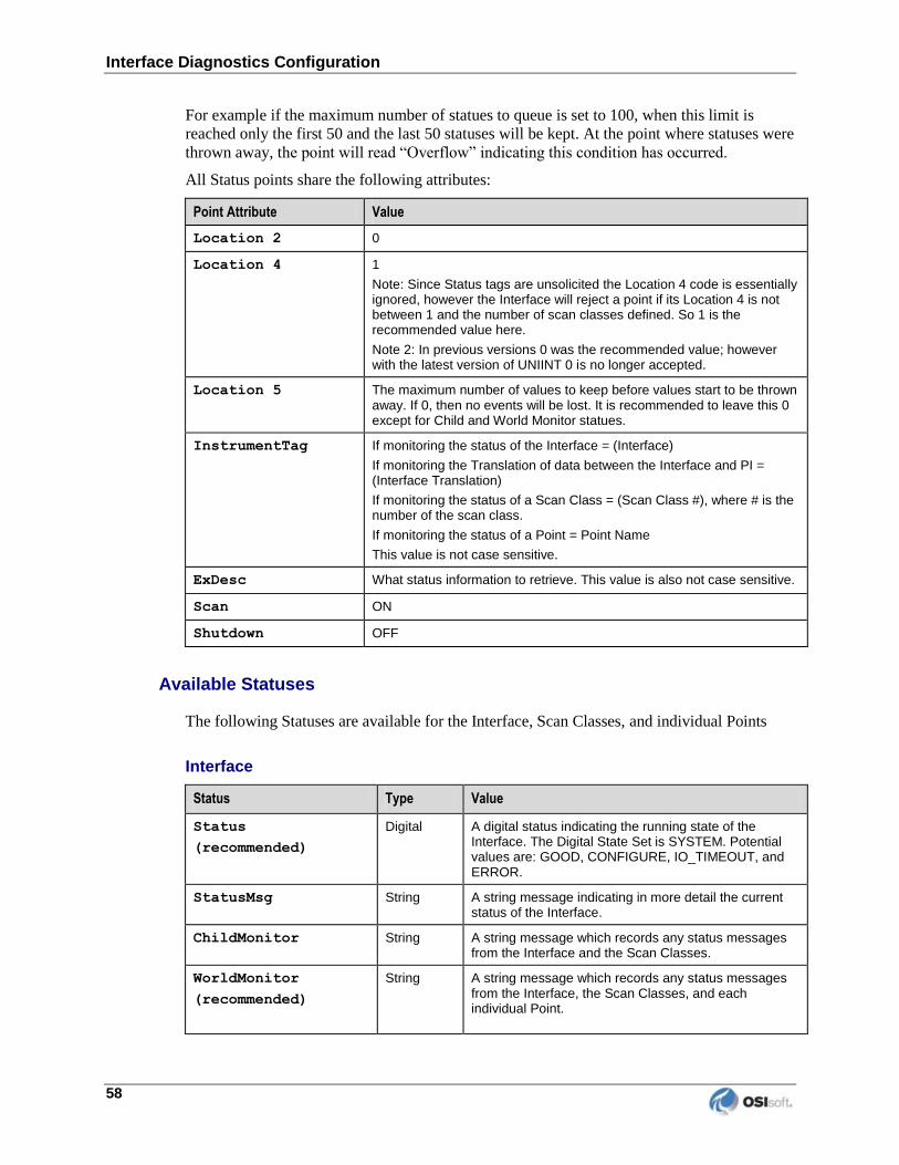
Interface Diagnostics Configuration
58
For example if the maximum number of statues to queue is set to 100, when this limit is
reached only the first 50 and the last 50 statuses will be kept. At the point where statuses were
thrown away, the point will read “Overflow” indicating this condition has occurred.
All Status points share the following attributes:
Point Attribute Value
Location 2 0
Location 4 1
Note: Since Status tags are unsolicited the Location 4 code is essentially ignored, however the Interface will reject a point if its Location 4 is not between 1 and the number of scan classes defined. So 1 is the recommended value here.
Note 2: In previous versions 0 was the recommended value; however with the latest version of UNIINT 0 is no longer accepted.
Location 5 The maximum number of values to keep before values start to be thrown away. If 0, then no events will be lost. It is recommended to leave this 0 except for Child and World Monitor statues.
InstrumentTag If monitoring the status of the Interface = (Interface)
If monitoring the Translation of data between the Interface and PI = (Interface Translation)
If monitoring the status of a Scan Class = (Scan Class #), where # is the number of the scan class.
If monitoring the status of a Point = Point Name
This value is not case sensitive.
ExDesc What status information to retrieve. This value is also not case sensitive.
Scan ON
Shutdown OFF
Available Statuses
The following Statuses are available for the Interface, Scan Classes, and individual Points
Interface
Status Type Value
Status
(recommended)
Digital A digital status indicating the running state of the Interface. The Digital State Set is SYSTEM. Potential values are: GOOD, CONFIGURE, IO_TIMEOUT, and ERROR.
StatusMsg String A string message indicating in more detail the current status of the Interface.
ChildMonitor String A string message which records any status messages from the Interface and the Scan Classes.
WorldMonitor
(recommended)
String A string message which records any status messages from the Interface, the Scan Classes, and each individual Point.
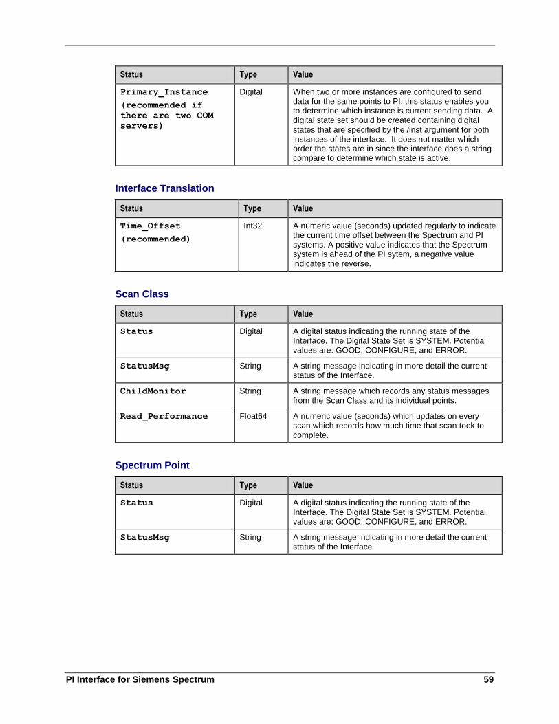
PI Interface for Siemens Spectrum 59
Status Type Value
Primary_Instance
(recommended if
there are two COM
servers)
Digital When two or more instances are configured to send data for the same points to PI, this status enables you to determine which instance is current sending data. A digital state set should be created containing digital states that are specified by the /inst argument for both instances of the interface. It does not matter which order the states are in since the interface does a string compare to determine which state is active.
Interface Translation
Status Type Value
Time_Offset
(recommended)
Int32 A numeric value (seconds) updated regularly to indicate the current time offset between the Spectrum and PI systems. A positive value indicates that the Spectrum system is ahead of the PI sytem, a negative value indicates the reverse.
Scan Class
Status Type Value
Status Digital A digital status indicating the running state of the Interface. The Digital State Set is SYSTEM. Potential values are: GOOD, CONFIGURE, and ERROR.
StatusMsg String A string message indicating in more detail the current status of the Interface.
ChildMonitor String A string message which records any status messages from the Scan Class and its individual points.
Read_Performance Float64 A numeric value (seconds) which updates on every scan which records how much time that scan took to complete.
Spectrum Point
Status Type Value
Status Digital A digital status indicating the running state of the Interface. The Digital State Set is SYSTEM. Potential values are: GOOD, CONFIGURE, and ERROR.
StatusMsg String A string message indicating in more detail the current status of the Interface.

PI Interface for Siemens Spectrum 61
Appendix A. Error and Informational Messages
A string NameID is pre-pended to error messages written to the message log. Name is a
non-configurable identifier that is no longer than 9 characters. ID is a configurable identifier
that is no longer than 9 characters and is specified using the /id parameter on the startup
command-line.
Message Logs
The location of the message log depends upon the platform on which the interface is running.
See the UniInt Interface User Manual for more information.
Messages are written to [PIHOME]\dat\ pimesslogfile at the following times.
When the interface starts many informational messages are written to the log. These
include the version of the interface, the version of UniInt, the command-line
parameters used, and the number of points.
As the interface loads points, messages are sent to the log if there are any problems
with the configuration of the points.
If the UniInt /dbUniInt parameter is found in the command-line, then various
informational messages are written to the log file.
Messages
Error Messages
Message Unable to Connect to default server.
Meaning The $PIHOME environment variable isn’t set or is set
incorrectly.
DEFAULTHOMENODE isn’t set or is set incorrectly in the
piclient.ini file.
Message PI to Interface Time Offset has exceeded # seconds = #
seconds, data loss occuring.
Meaning When the COM server is the Time Source and PI time falls
more than 10 minutes behind, data loss will occur.
Error and Informational Messages
62
Message PI to Interface Time Offset has exceeded maximum (#) = #
seconds
Meaning With /hto set, if the COM time drifts from PI time greater
than the specified number of seconds, this error is
reported.
Message PI to Interface Time Offset has jumped # seconds
Meaning If the time difference between COM and PI time jumps more
than 5 seconds, this error is reported.
Message Relation NOEL: #, INFO: # is invalid. Function <name>,
Status #
Meaning There was an error reading from this Spectrum relation.
Message NOEL is missing or invalid
INFO is missing or invalid
NIMSET is missing or invalid
Meaning Error message generated when a point is misconfigured.
Message Relation is missing or invalid
Meaning Error Message generated when the Spectrum relation a point
belongs to cannot be read.
Message Noel: #, Info #, Element # is missing or invalid.
Meaning Error Message generated when the Spectrum relation a point
belongs fails to contain this specific element.
PI Interface for Siemens Spectrum 63
Message Unable to obtain digital range for tag tagname
Meaning The first time the interface attempts to process a digital
point, it will query the valid range for the associated
digital state set and cache this information locally. This
message indicates that the query attempt failed. This could
be caused by a loss of connectivity with the PI Server or a
misconfigured PI tag.
Message Digital state value out of bounds for tagname at: XX, Low:
0, High: YY
Meaning If a digital point (tagname) is found to have a value (XX)
outside the range of the point’s associated digital state
set (0 to YY), this warning message will be reported. The
interface will still attempt to send the value to the PI
Server.
If the message is accompanied by a -10702 error (Istat
greater than span for digital set), then the data for the
associated point is being discarded (i.e. not being
archived).
Possible causes for a digital point having a value outside
the assigned range are that the Spectrum system is sending
an unexpected value or the point’s associated digital state
set is misconfigured and should be verified.
It is also possible to see this if using disconnected
startup and the cached point attributes on the interface
node are not current with the points on the PI Server.
This can be corrected by stopping the interface, deleting
the local disconnected startup caches, and then restarting
the interface. This will cause the caches to be recreated
with current PI point attributes.
Another option is to perform a non-consequential edit on
the affected PI points, which will force the update to
cascade to the interface node and disconnected startup
cache. This could be done by simply importing the affected
tags into PI DataLink and then exporting them, using the
“Edit” mode, but without making any changes to the tags.
This will clear the -10702 error, meaning data is no longer
being discarded. To clear the “out of bounds” warning
message, restart the interface.
Error and Informational Messages
64
Spectrum States
Message Spectrum State: NotStarted
Meaning The Interface has not yet attempted to connect to Spectrum.
Message Start
Meaning The Interface has started.
Message BeforeSoftInit
Meaning The Interface is about to connect for the first time to
Spectrum.
Message SoftInitFailed - Interface Exiting
Meaning The Interface has failed to connect to Spectrum.
Message BeforeWaitForSoftInit
Meaning The Interface is about to enter a waiting period where it
will receive a SoftInit signal from Spectrum.
Message IgnitionFailed - Interface Exiting
Meaning The Interface has failed to read any SoftInit signal from
Spectrum.
Message IgnitionSucceeded
Meaning The Interface has successfully received a SoftInit signal
from Spectrum.
Message ProcessControl
Meaning The Interface is the currently sending data to PI.
PI Interface for Siemens Spectrum 65
Message Standby
Meaning The Interface is running in a backup capacity in a Hot
Failover environment.
Message CheckSoftbusFailed - Interface Exiting
Meaning The Interface has encountered an error while reading from
the Softbus message queue.
Message EndProg - Interface Exiting
Meaning The Interface will shut down now after receiving an EndProg
signal from Spectrum.
System Errors and PI Errors
System errors are associated with positive error numbers. Errors related to PI are associated
with negative error numbers.
Error Descriptions on UNIX
On UNIX, descriptions of system and PI errors can be obtained with the pidiag utility:
UNIX: /PI/adm/pidiag –e error_number

PI Interface for Siemens Spectrum 67
Appendix B. Terminology
To understand this interface manual, you should be familiar with the terminology used in this
document.
Buffering
Buffering refers to an interface node’s ability to store temporarily the data that interfaces
collect and to forward these data to the appropriate PI Servers.
N-Way Buffering
If you have PI Servers that are part of a PI Collective, PIBufss supports n-way buffering.
N-way buffering refers to the ability of a buffering application to send the same data to each
of the PI Servers in a PI Collective. (Bufserv also supports n-way buffering to multiple PI
Servers however it does not guarantee identical archive records since point compressions
attributes could be different between PI Servers. With this in mind, OSIsoft recommends that
you run PIBufss instead.)
ICU
ICU refers to the PI Interface Configuration Utility. The ICU is the primary application that
you use to configure PI interface programs. You must install the ICU on the same computer
on which an interface runs. A single copy of the ICU manages all of the interfaces on a
particular computer.
You can configure an interface by editing a startup command file. However, OSIsoft
discourages this approach. Instead, OSIsoft strongly recommends that you use the ICU for
interface management tasks.
ICU Control
An ICU Control is a plug-in to the ICU. Whereas the ICU handles functionality common to
all interfaces, an ICU Control implements interface-specific behavior. Most PI interfaces
have an associated ICU Control.
Interface Node
An interface node is a computer on which
the PI API and/or PI SDK are installed, and
PI Server programs are not installed.
PI API
The PI API is a library of functions that allow applications to communicate and exchange
data with the PI Server. All PI interfaces use the PI API.
Terminology
68
PI Collective
A PI Collective is two or more replicated PI Servers that collect data concurrently.
Collectives are part of the High Availability environment. When the primary PI Server in a
collective becomes unavailable, a secondary collective member node seamlessly continues to
collect and provide data access to your PI clients.
PIHOME
PIHOME refers to the directory that is the common location for PI 32-bit client applications.
A typical PIHOME on a 32-bit operating system is C:\Program Files\PIPC.
A typical PIHOME on a 64-bit operating system is C:\Program Files (x86)\PIPC.
PI 32-bit interfaces reside in a subdirectory of the Interfaces directory under PIHOME.
For example, files for the 32-bit Modbus Ethernet Interface are in
[PIHOME]\PIPC\Interfaces\ModbusE.
This document uses [PIHOME] as an abbreviation for the complete PIHOME or PIHOME64
directory path. For example, ICU files in [PIHOME]\ICU.
PIHOME64
PIHOME64 is found only on a 64-bit operating system and refers to the directory that is the
common location for PI 64-bit client applications.
A typical PIHOME64 is C:\Program Files\PIPC.
PI 64-bit interfaces reside in a subdirectory of the Interfaces directory under PIHOME64.
For example, files for a 64-bit Modbus Ethernet Interface would be found in
C:\Program Files\PIPC\Interfaces\ModbusE.
This document uses [PIHOME] as an abbreviation for the complete PIHOME or PIHOME64
directory path. For example, ICU files in [PIHOME]\ICU.
PI Message Log
The PI message log is the file to which OSIsoft interfaces based on UniInt 4.5.0.x and later
write informational, debug and error messages. When a PI interface runs, it writes to the
local PI message log. This message file can only be viewed using the PIGetMsg utility. See
the UniInt Interface Message Logging.docx file for more information on how to access these
messages.
PI SDK
The PI SDK is a library of functions that allow applications to communicate and exchange
data with the PI Server. Some PI interfaces, in addition to using the PI API, require the use of
the PI SDK.
PI Server Node
A PI Server Node is a computer on which PI Server programs are installed. The PI Server
runs on the PI Server Node.

PI Interface for Siemens Spectrum 69
PI SMT
PI SMT refers to PI System Management Tools. PI SMT is the program that you use for
configuring PI Servers. A single copy of PI SMT manages multiple PI Servers. PI SMT runs
on either a PI Server Node or a interface node.
Pipc.log
The pipc.log file is the file to which OSIsoft applications write informational and error
messages. When a PI interface runs, it writes to the pipc.log file. The ICU allows easy
access to the pipc.log.
Point
The PI point is the basic building block for controlling data flow to and from the PI Server.
For a given timestamp, a PI point holds a single value.
A PI point does not necessarily correspond to a “point” on the foreign device. For example, a
single “point” on the foreign device can consist of a set point, a process value, an alarm limit,
and a discrete value. These four pieces of information require four separate PI points.
Service
A Service is a Windows program that runs without user interaction. A Service continues to
run after you have logged off from Windows. It has the ability to start up when the computer
itself starts up.
The ICU allows you to configure a PI interface to run as a Service.
Tag (Input Tag and Output Tag)
The tag attribute of a PI point is the name of the PI point. There is a one-to-one
correspondence between the name of a point and the point itself. Because of this relationship,
PI System documentation uses the terms “tag” and “point” interchangeably.
Interfaces read values from a device and write these values to an Input Tag. Interfaces use an
Output Tag to write a value to the device.


PI Interface for Siemens Spectrum 71
Appendix C. Technical Support and Resources
You can read complete information about technical support options, and access all of the
following resources at the OSIsoft Technical Support Web site:
http://techsupport.osisoft.com (http://techsupport.osisoft.com)
Before You Call or Write for Help
When you contact OSIsoft Technical Support, please provide:
Product name, version, and/or build numbers
Computer platform (CPU type, operating system, and version number)
The time that the difficulty started
The log file(s) at that time
Help Desk and Telephone Support
You can contact OSIsoft Technical Support 24 hours a day. Use the numbers in the table
below to find the most appropriate number for your area. Dialing any of these numbers will
route your call into our global support queue to be answered by engineers stationed around
the world.
Office Location Access Number Local Language Options
San Leandro, CA, USA 1 510 297 5828 English
Philadelphia, PA, USA 1 215 606 0705 English
Johnson City, TN, USA 1 423 610 3800 English
Montreal, QC, Canada 1 514 493 0663 English, French
Sao Paulo, Brazil 55 11 3053 5040 English, Portuguese
Frankfurt, Germany 49 6047 989 333 English, German
Manama, Bahrain 973 1758 4429 English, Arabic
Singapore 65 6391 1811
86 021 2327 8686
English, Mandarin
Mandarin
Perth, WA, Australia 61 8 9282 9220 English

Technical Support and Resources
72
Support may be provided in languages other than English in certain centers (listed above)
based on availability of attendants. If you select a local language option, we will make best
efforts to connect you with an available Technical Support Engineer (TSE) with that language
skill. If no local language TSE is available to assist you, you will be routed to the first
available attendant.
If all available TSEs are busy assisting other customers when you call, you will be prompted
to remain on the line to wait for the next available TSE or else leave a voicemail message. If
you choose to leave a message, you will not lose your place in the queue. Your voicemail
will be treated as a regular phone call and will be directed to the first TSE who becomes
available.
If you are calling about an ongoing case, be sure to reference your case number when you call
so we can connect you to the engineer currently assigned to your case. If that engineer is not
available, another engineer will attempt to assist you.
Search Support
From the OSIsoft Technical Support Web site, click Search Support.
Quickly and easily search the OSIsoft Technical Support Web site’s Support Solutions,
Documentation, and Support Bulletins using the advanced MS SharePoint search engine.
Email-based Technical Support
When contacting OSIsoft Technical Support by email, it is helpful to send the following
information:
Description of issue: Short description of issue, symptoms, informational or error
messages, history of issue
Log files: See the product documentation for information on obtaining logs pertinent
to the situation.
Online Technical Support
From the OSIsoft Technical Support Web site, click Contact us > My Support > My Calls.
Using OSIsoft’s Online Technical Support, you can:
Enter a new call directly into OSIsoft’s database (monitored 24 hours a day)
View or edit existing OSIsoft calls that you entered
View any of the calls entered by your organization or site, if enabled
See your licensed software and dates of your Service Reliance Program agreements
PI Interface for Siemens Spectrum 73
Remote Access
From the OSIsoft Technical Support Web site, click Contact Us > Remote Support Options.
OSIsoft Support Engineers may remotely access your server in order to provide hands-on
troubleshooting and assistance. See the Remote Access page for details on the various
methods you can use.
On-site Service
From the OSIsoft Technical Support Web site, click Contact Us > On-site Field Service Visit.
OSIsoft provides on-site service for a fee. Visit our On-site Field Service Visit page for more
information.
Knowledge Center
From the OSIsoft Technical Support Web site, click Knowledge Center.
The Knowledge Center provides a searchable library of documentation and technical data, as
well as a special collection of resources for system managers. For these options, click
Knowledge Center on the Technical Support Web site.
The Search feature allows you to search Support Solutions, Bulletins, Support Pages,
Known Issues, Enhancements, and Documentation (including user manuals, release
notes, and white papers).
System Manager Resources include tools and instructions that help you manage:
Archive sizing, backup scripts, daily health checks, daylight savings time
configuration, PI Server security, PI System sizing and configuration, PI trusts for
interface nodes, and more.
Upgrades
From the OSIsoft Technical Support Web site, click Contact Us > Obtaining Upgrades.
You are eligible to download or order any available version of a product for which you have
an active Service Reliance Program (SRP), formerly known as Tech Support Agreement
(TSA). To verify or change your SRP status, contact your Sales Representative or Technical
Support (http://techsupport.osisoft.com/) for assistance.
OSIsoft Virtual Campus (vCampus)
The OSIsoft Virtual Campus (vCampus) Web site offers a community-oriented program that
focuses on PI System development and integration. The Web site's annual online
subscriptions provide customers with software downloads, resources that include a personal
development PI System, online library, technical webinars, online training, and community-
oriented features such as blogs and discussion forums.
OSIsoft vCampus is intended to facilitate and encourage communication around PI
programming and integration between OSIsoft partners, customers and employees. See the

Technical Support and Resources
74
OSIsoft vCampus Web site, http://vCampus.osisoft.com (http://vCampus.osisoft.com) or
contact the OSIsoft vCampus team at [email protected] for more information.

PI Interface for Siemens Spectrum 75
Appendix D. Revision History
Date Author Comments
07-Dec-2001 CG Changed some ICU headings; skeleton version 1.11
13-Jun-2002 SMS First Draft
17-Jun-2002 SMS Round 1 of edits by JFZ and SMS
26-Aug-2002 SMS Minor modifications
19-Nov-2002 SMS Second Draft. With more details filled in.
23-Jan-2003 SMS Some updates
30-Jan-2003 JZ Major revision based on trip to Siemens in Minneapolis
07-Feb-2003 SMS More updates.
17-Feb-2003 SMS Yet more updates.
28-Feb-2003 SMS More options and info about status points. Also, program is now called sspectrum for Siemens Spectrum Interface.
13-Mar-2003 SMS Accepted Julie’s changes and made a few of my own.
25-Mar-2003 SMS Added section on the ICU control with screenshots
06-Jun-2003 SMS First released version of the Interface.
30-Jun-2003 SMS Changed the name of the Spectrum program from SSpectrumPI to sspec_pi because Spectrum only allows for 8 chars or less.
08-Jul-2003 SMS Cleaned up the document for version 1.0.2.1
03-Sep-2003 SMS Updated to reflec the multi-process design.
15-Sep-2003 SMS Updated version to 1.0.3.1 after fixes implemented on PJM trip.
06-Nov-2003 SMS Updated version to 1.0.3.3 after adding the /dsa flag and other minor fixes to aid debugging.
05-Dec-2003 SMS Updated version to 1.0.3.6 after putting in some significant performance enhancements
27-Feb-2004 SMS Updated to 1.0.3.7, added READ_PERFORMANCE status to Scan Classes, needed because Uniint Performance Points don’t know when not to write in a hot failover situation.
13-May-2004 SMS Updated to 1.0.4.3, resolved an issue where sometimes the Interface would die after losing its connection to PI. If the Interface stopped scanning for a minute due to a communication timeout, Spectrum would think the Interface was hung and kill the process.
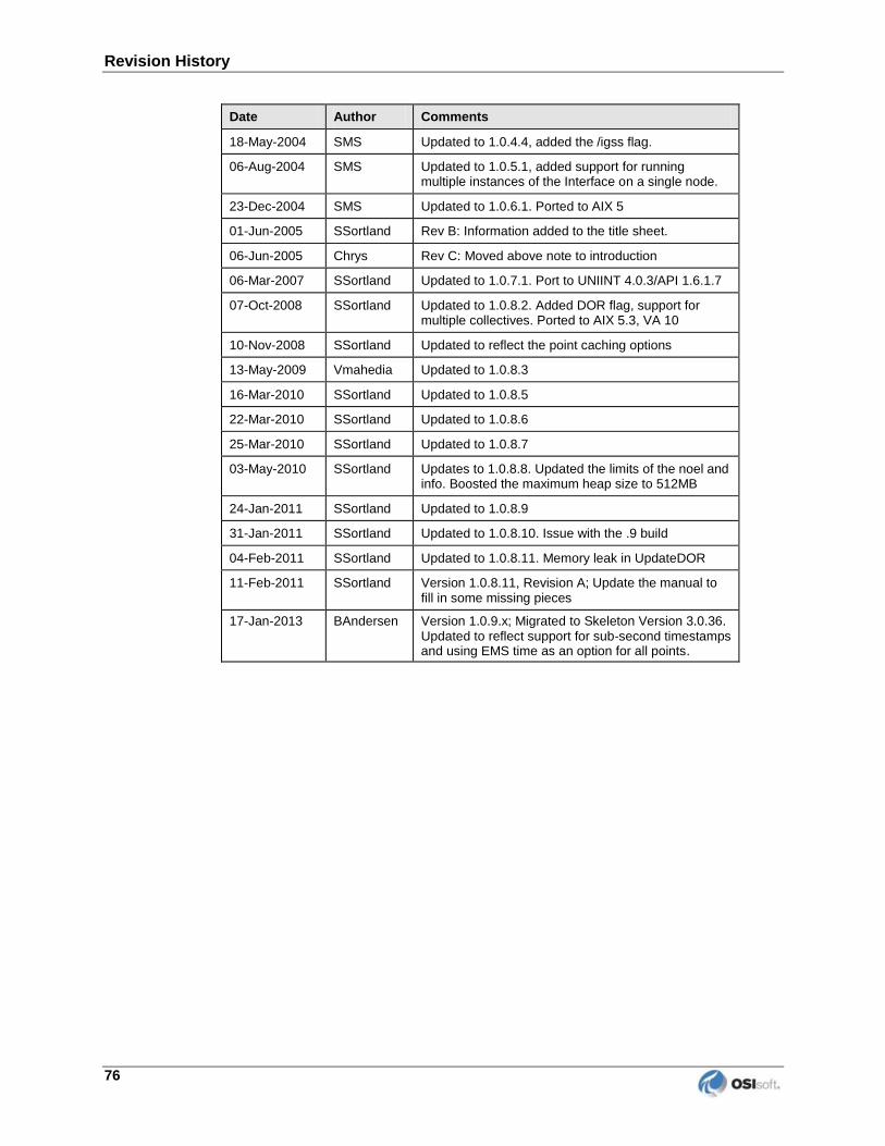
Revision History
76
Date Author Comments
18-May-2004 SMS Updated to 1.0.4.4, added the /igss flag.
06-Aug-2004 SMS Updated to 1.0.5.1, added support for running multiple instances of the Interface on a single node.
23-Dec-2004 SMS Updated to 1.0.6.1. Ported to AIX 5
01-Jun-2005 SSortland Rev B: Information added to the title sheet.
06-Jun-2005 Chrys Rev C: Moved above note to introduction
06-Mar-2007 SSortland Updated to 1.0.7.1. Port to UNIINT 4.0.3/API 1.6.1.7
07-Oct-2008 SSortland Updated to 1.0.8.2. Added DOR flag, support for multiple collectives. Ported to AIX 5.3, VA 10
10-Nov-2008 SSortland Updated to reflect the point caching options
13-May-2009 Vmahedia Updated to 1.0.8.3
16-Mar-2010 SSortland Updated to 1.0.8.5
22-Mar-2010 SSortland Updated to 1.0.8.6
25-Mar-2010 SSortland Updated to 1.0.8.7
03-May-2010 SSortland Updates to 1.0.8.8. Updated the limits of the noel and info. Boosted the maximum heap size to 512MB
24-Jan-2011 SSortland Updated to 1.0.8.9
31-Jan-2011 SSortland Updated to 1.0.8.10. Issue with the .9 build
04-Feb-2011 SSortland Updated to 1.0.8.11. Memory leak in UpdateDOR
11-Feb-2011 SSortland Version 1.0.8.11, Revision A; Update the manual to fill in some missing pieces
17-Jan-2013 BAndersen Version 1.0.9.x; Migrated to Skeleton Version 3.0.36. Updated to reflect support for sub-second timestamps and using EMS time as an option for all points.


![Field Instruments for Process Automationcnnindustrial.com/pdf/SIEMENS PI General Catalogue.pdf · 8 Siemens FI 01 · 2015 [1] [2] [3] Pressure Measurement SITRANS P Compact [1] For](https://img.pdfslide.us/doc/110x75/5bc8e85f09d3f272268becf4/field-instruments-for-process-aut-pi-general-cataloguepdf-8-siemens-fi-01-.jpg)