Embed Size (px)
Citation preview
PERMISSION TO PRINT RESEARCH COPIES GRANTED BY JOBE CONSULTING LLC 1
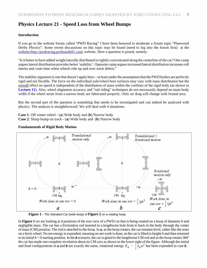
Figure 1 - The Standard Car (wide body) of Figure 2 on a rotating hoop.
Physics Lecture 21 - Speed Loss from Wheel Bumps
Introduction
If you go to the website forum called “PWD Racing” I have been honored to moderate a forum topic “PinewoodDerby Physics”. Some recent discussions on this topic may be found (need to log into the forum first) at thewebsite:http://pwdracing.proboards91.com/ website. Here a question is posed, namely:
“Is it better to have added weight laterally distributed or tightly concentrated along the centerline of the car? One campargues lateral distribution provides better ‘stability’. Opposite camp argues increased lateral distribution increases rollinertia and costs time when wheels ride up and over track debris.”
The stability argument is one that doesn’t apply here—at least under the assumption that the PWD bodies are perfectlyrigid and not flexible. The force on the individual axle/wheel bore surfaces may vary with mass distribution but theoverall effect on speed is independent of the distribution of mass within the confines of the rigid body (as shown inLecture 11). Also, wheel alignment accuracy and “rail riding” techniques do not necessarily depend on main bodywidth if the wheel struts from a narrow body are fabricated properly. Only air drag will change with frontal area.
But the second part of the question is something that needs to be investigated and can indeed be analyzed withphysics. The analysis is straightforward. We will deal with 4 situations:
Case 1: Off center wheel - (a) Wide body and (b) Narrow bodyCase 2: Sharp bump on track - (a) Wide body and (b) Narrow body
Fundamentals of Rigid Body Motion
In Figure 1 we are looking at 4 positions of the rear view of a PWD car that is being rotated on a hoop of diameter h andnegligible mass. The car has a frictionless rod inserted in a lengthwise hole front to back in the body through the centerof mass (CM) position. The rod is attached to the hoop. In a, as the hoop rotates, the car remains level, rather like the seatson a ferris wheel. No net energy is expended, meaning no net work is done, as the car is lifted to height h and then returnedto its initial h = 0 starting position. In the b scenario, the car is glued to the lengthwise CM rod and as the hoop rotates 360o
the car has made one complete revolution about its CM axis as shown in the lower right of the figure. Although the initialand final configurations in a and b are exactly the same, rotational energy has been expended in case b.ER �
1
2IB�
2
PERMISSION TO PRINT RESEARCH COPIES GRANTED BY JOBE CONSULTING LLC 2
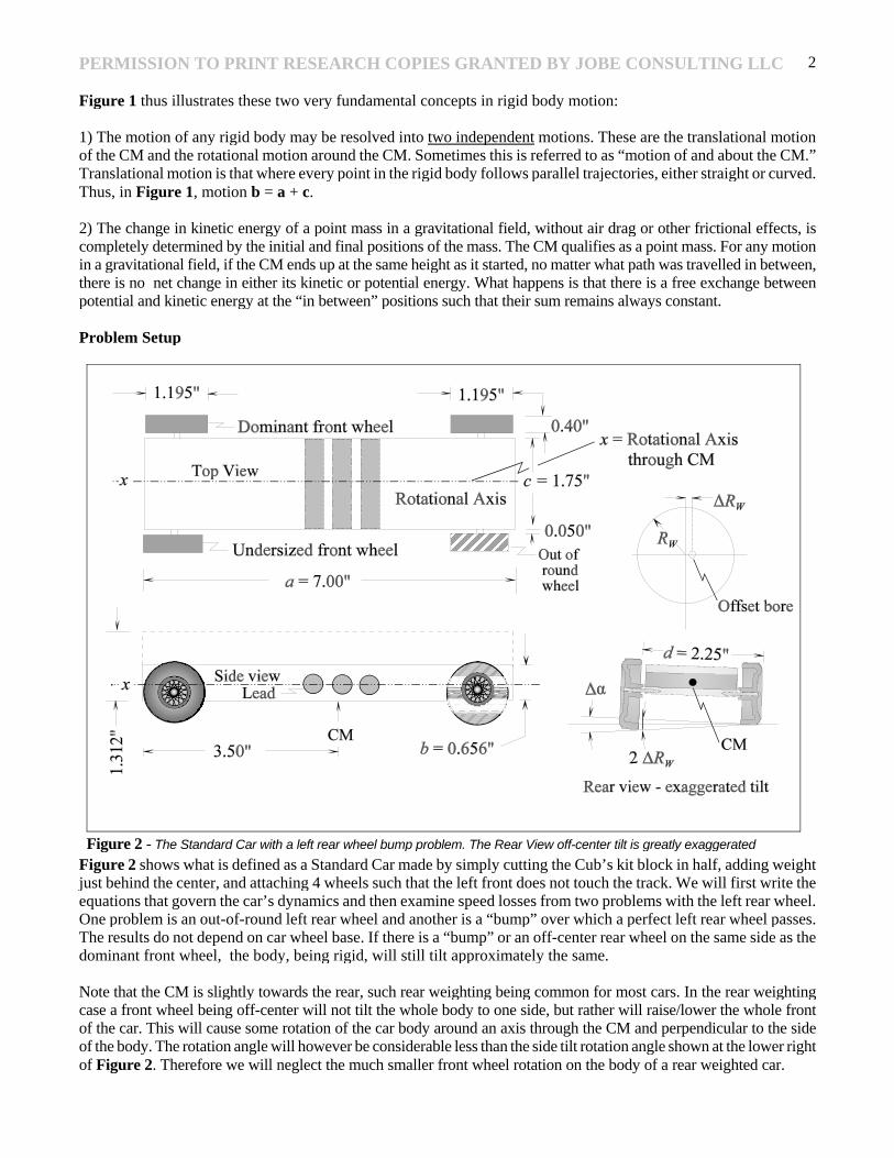
Figure 2 - The Standard Car with a left rear wheel bump problem. The Rear View off-center tilt is greatly exaggerated
Figure 1 thus illustrates these two very fundamental concepts in rigid body motion:
1) The motion of any rigid body may be resolved into two independent motions. These are the translational motionof the CM and the rotational motion around the CM. Sometimes this is referred to as “motion of and about the CM.”Translational motion is that where every point in the rigid body follows parallel trajectories, either straight or curved.Thus, in Figure 1, motion b = a + c.
2) The change in kinetic energy of a point mass in a gravitational field, without air drag or other frictional effects, iscompletely determined by the initial and final positions of the mass. The CM qualifies as a point mass. For any motionin a gravitational field, if the CM ends up at the same height as it started, no matter what path was travelled in between,there is no net change in either its kinetic or potential energy. What happens is that there is a free exchange betweenpotential and kinetic energy at the “in between” positions such that their sum remains always constant.
Problem Setup
Figure 2 shows what is defined as a Standard Car made by simply cutting the Cub’s kit block in half, adding weightjust behind the center, and attaching 4 wheels such that the left front does not touch the track. We will first write theequations that govern the car’s dynamics and then examine speed losses from two problems with the left rear wheel.One problem is an out-of-round left rear wheel and another is a “bump” over which a perfect left rear wheel passes.The results do not depend on car wheel base. If there is a “bump” or an off-center rear wheel on the same side as thedominant front wheel, the body, being rigid, will still tilt approximately the same.
Note that the CM is slightly towards the rear, such rear weighting being common for most cars. In the rear weightingcase a front wheel being off-center will not tilt the whole body to one side, but rather will raise/lower the whole frontof the car. This will cause some rotation of the car body around an axis through the CM and perpendicular to the sideof the body. The rotation angle will however be considerable less than the side tilt rotation angle shown at the lower rightof Figure 2. Therefore we will neglect the much smaller front wheel rotation on the body of a rear weighted car.
PERMISSION TO PRINT RESEARCH COPIES GRANTED BY JOBE CONSULTING LLC 3
EP � Mgh (1)
EK �
1
2Mv 2
(2)
ET � EP � EK� Mgy �
1
2Mv 2
� constant (3)
ET � EP� Mgh � constant (4)
ET � EK�1
2Mv 2
� constant (Note all these constants have the same value) (5)
1
2Mv 2
� Mgh (6)
v � 2gh (7)
ER �
1
2IB�
2(8)
� �
��
�t(9)
Energy Laws
The approach to the problem will use the conservation of energy laws. The total energy, due to a certain starting rampheight y = h of the center of mass of the car above the finish line level, is all potential and is given by
Here M is the mass of the car, g is the acceleration of gravity, and EP is the potential energy. After the start, thispotential energy is all converted into kinetic energy EK on the straight level run to the finish, thus at the finish linewhere y = 0 we have
Actually, one could look at it this way. Anywhere in a gravitational field, we have the total car energy ET as
So when v = 0 at the starting CM height y = h we have
And when we have the height y unchanging at a reference value y = 0 we have
Thus, since two quantities that equal the same quantity must equal each other, the energy at the start must equal theenergy at the finish (wheel/axle friction, air drag, and wheel moment of inertia are assumed negligible). Therefore
This rather simple equation is very useful for determining race car velocity.
All the above energy is translational (because we neglect the small wheel rotational energy). However, if a wheel isout-of-round, the body can be twisted around an axis parallel to the direction of travel. For example, in Figure 2wehave a wheel of radius RW wherein the bore is off center by a small amount �RW. In the lower right we see that thewheel can rotate the body by some angle � as the car rolls down the track. This rotational energy ER is given by
In (8), IB is the moment of inertia of the body around a longitudinal axis through its CM and � is the angular velocityof the rotation.
The approach here is to calculate (8) and use it to reduce the amount of energy (5) so that the overall energy remainsconstant. But as we can see from (6) and (7), this means a lower v. This will be calculated later.
First, we will look at the dynamics of the wheel bumps so we can deduce the angular velocity �. In (9) below, ��is the maximum angle change and �t is the time corresponding to that angle change
PERMISSION TO PRINT RESEARCH COPIES GRANTED BY JOBE CONSULTING LLC 4
�x �
�
2(2RW � �RW) (10)
�t �
�xv
�
�RW
v(11)
� �
��
�t�
2v�RW
d�x�
2v�RW
d�RW(12)
� �
2�RW 2gh
d�RW
(13)
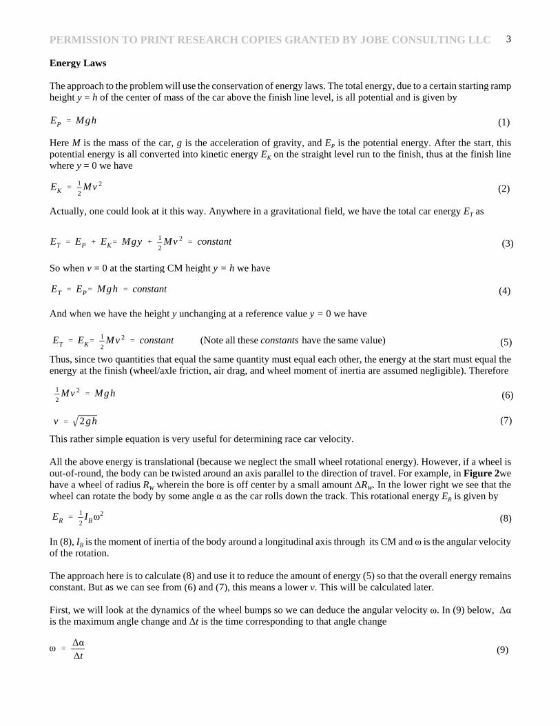
Figure 3 - The motion of a point off center on a rolling wheel describes a trochoid (red line).
Case 1(a) - Out-of -Round (off - Center) Wheel
Figure 3 shows a wheel rolling to the right at velocity v. The bore hole is offset an amount �RW. As the wheel rollsthe bore hole describes the trochoid curve shown in red. It is similar to the cycloid curve formed by a point on the rimof the rolling wheel but it is a much shallower curve. Here the �RW offset is exaggerated to 30% of the radius forclarity. We can approximate the red line at the left by the blue straight line over the distances shown. The red linecurvature does not change much at the very top of the trochoid so the blue line only extends over 1/4 rotation. As onecan see from the figure, the rolling distance (and the time �t ) is slightly longer when the wheel bore is raising thenear body side compared to when is dropping it below its level position. The total rolling distance when eitherincreasing or when decreasing the angle � is
However, even a large �RW could be like 0.010" and the wheel diameter 2 RW is about 1.20". So the effect on the ��we will consider will usually be less than 1%. Thus, we can neglect �RW in (10) and get for a rolling distance and timefor an � increase (or a decrease),
The angle change in � for this � t is � �, and is, in radian measure ( 2� radians = 360o), to a good approximation givenby its tangent, which is simply the “rise over run”. The run, as seen in Figure 1, is the distance d = 2.25" and the riseis of course 2�RW. So we have from (9)
From (7) we can substitute for v giving
The rotational energy from one “bump” is thus from (8)
PERMISSION TO PRINT RESEARCH COPIES GRANTED BY JOBE CONSULTING LLC 5
ER �
1
2IB�
2� IB gh
2�RW
d�RW
2
(14)
IB �
1
12m (b 2
� c 2) (15)
ER �
1
12m (b 2
� c 2)gh2�RW
d�RW
2
(16)
ER �
2N12
m (b 2� c 2)gh
2�RW
d�RW
2
(18)
N �
l2�RW
(17)
ER �
1
2Mv 2
2 � Mgh (19)
v2 � 2gh �
2ER
M(20)
t2 �
l
2gh �
2ER
M
(21)
t �
l
2ghwhere t is the time with no wheel bumping, i.e., ER � 0 (22)
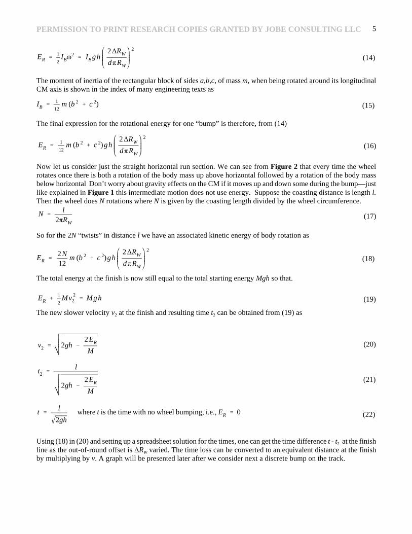
The moment of inertia of the rectangular block of sides a,b,c, of mass m, when being rotated around its longitudinalCM axis is shown in the index of many engineering texts as
The final expression for the rotational energy for one “bump” is therefore, from (14)
Now let us consider just the straight horizontal run section. We can see from Figure 2 that every time the wheelrotates once there is both a rotation of the body mass up above horizontal followed by a rotation of the body massbelow horizontal Don’t worry about gravity effects on the CM if it moves up and down some during the bump—justlike explained in Figure 1 this intermediate motion does not use energy. Suppose the coasting distance is length l.Then the wheel does N rotations where N is given by the coasting length divided by the wheel circumference.
So for the 2N “twists” in distance l we have an associated kinetic energy of body rotation as
The total energy at the finish is now still equal to the total starting energy Mgh so that.
The new slower velocity v2 at the finish and resulting time t2 can be obtained from (19) as
Using (18) in (20) and setting up a spreadsheet solution for the times, one can get the time difference t - t2 at the finishline as the out-of-round offset is �RW varied. The time loss can be converted to an equivalent distance at the finishby multiplying by v. A graph will be presented later after we consider next a discrete bump on the track.
PERMISSION TO PRINT RESEARCH COPIES GRANTED BY JOBE CONSULTING LLC 6
�x � 2 �RW (2RW � �RW ) (23)
� �
��
�t�
v�RW
d�x�
v�RW
2d �RW (2RW � �RW )(22)
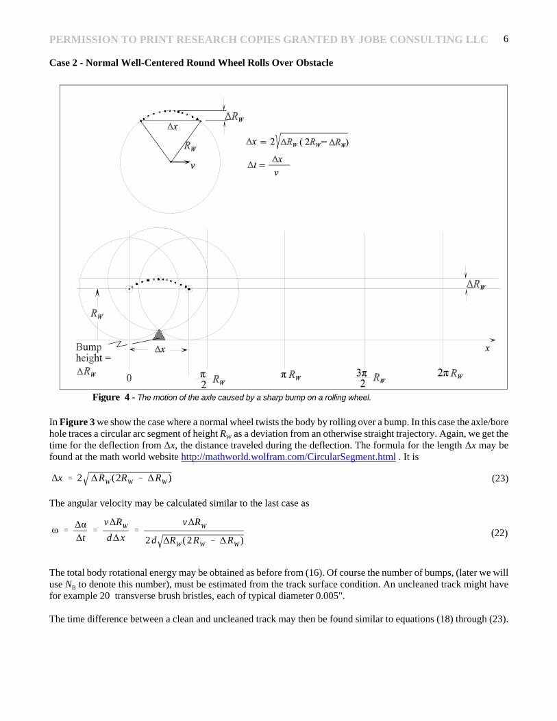
Figure 4 - The motion of the axle caused by a sharp bump on a rolling wheel.
Case 2 - Normal Well-Centered Round Wheel Rolls Over Obstacle
In Figure 3 we show the case where a normal wheel twists the body by rolling over a bump. In this case the axle/borehole traces a circular arc segment of height RW as a deviation from an otherwise straight trajectory. Again, we get thetime for the deflection from �x, the distance traveled during the deflection. The formula for the length �x may befound at the math world website http://mathworld.wolfram.com/CircularSegment.html . It is
The angular velocity may be calculated similar to the last case as
The total body rotational energy may be obtained as before from (16). Of course the number of bumps, (later we willuse NB to denote this number), must be estimated from the track surface condition. An uncleaned track might havefor example 20 transverse brush bristles, each of typical diameter 0.005".
The time difference between a clean and uncleaned track may then be found similar to equations (18) through (23).
PERMISSION TO PRINT RESEARCH COPIES GRANTED BY JOBE CONSULTING LLC 7
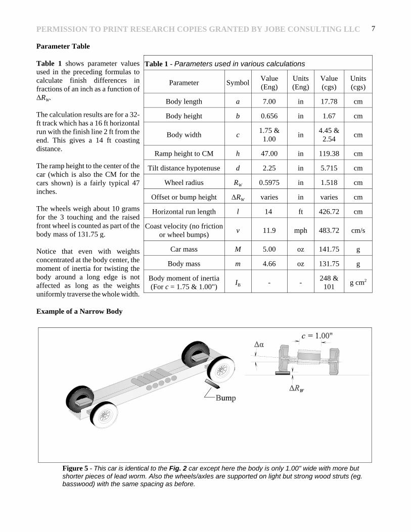
Table 1 - Parameters used in various calculations
Parameter SymbolValue(Eng)
Units(Eng)
Value(cgs)
Units(cgs)
Body length a 7.00 in 17.78 cm
Body height b 0.656 in 1.67 cm
Body width c1.75 &
1.00in
4.45 &2.54
cm
Ramp height to CM h 47.00 in 119.38 cm
Tilt distance hypotenuse d 2.25 in 5.715 cm
Wheel radius RW 0.5975 in 1.518 cm
Offset or bump height �RW varies in varies cm
Horizontal run length l 14 ft 426.72 cm
Coast velocity (no frictionor wheel bumps)
v 11.9 mph 483.72 cm/s
Car mass M 5.00 oz 141.75 g
Body mass m 4.66 oz 131.75 g
Body moment of inertia(For c = 1.75 & 1.00")
IB - -248 &
101g cm2
Figure 5 - This car is identical to the Fig. 2 car except here the body is only 1.00" wide with more butshorter pieces of lead worm. Also the wheels/axles are supported on light but strong wood struts (eg.basswood) with the same spacing as before.
Parameter Table
Table 1 shows parameter valuesused in the preceding formulas tocalculate finish differences infractions of an inch as a function of�RW.
The calculation results are for a 32-ft track which has a 16 ft horizontalrun with the finish line 2 ft from theend. This gives a 14 ft coastingdistance.
The ramp height to the center of thecar (which is also the CM for thecars shown) is a fairly typical 47inches.
The wheels weigh about 10 gramsfor the 3 touching and the raisedfront wheel is counted as part of thebody mass of 131.75 g.
Notice that even with weightsconcentrated at the body center, themoment of inertia for twisting thebody around a long edge is notaffected as long as the weightsuniformly traverse the whole width.
Example of a Narrow Body
PERMISSION TO PRINT RESEARCH COPIES GRANTED BY JOBE CONSULTING LLC 8
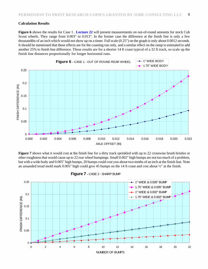
Figure 6 - CASE 1 - OUT OF ROUND REAR WHEEL
0
0.05
0.1
0.15
0.2
0.25
0.000 0.002 0.004 0.006 0.008 0.010 0.012 0.014 0.016 0.018 0.020 0.022
AXLE OFFSET (IN)
FIN
ISH
DIF
FE
RE
NC
E (
IN)
.
1" WIDE BODY
1.75" WIDE BODY
Figure 7 - CASE 2 - SHARP BUMP
0
0.05
0.1
0.15
0.2
0.25
0 2 4 6 8 10 12 14 16 18 20 22
NUMBER OF BUMPS
FIN
ISH
DIF
FER
EN
CE
(IN
) .
1" WIDE & 0.005" BUMP
1.75" WIDE & 0.005" BUMP
1" WIDE & 0.002" BUMP
1.75" WIDE & 0.002" BUMP
Calculation Results
Figure 6 shows the results for Case 1 . Lecture 22 will present measurements on out-of-round amounts for stock CubScout wheels. They range from 0.003" to 0.013". In the former case the difference at the finish line is only a fewthousandths of an inch which would not show up on a timer. Full scale (0.25") on the graph is only about 0.0012 seconds.It should be mentioned that these effects are for the coasting run only, and a similar effect on the ramp is estimated to addanother 25% to finish line difference. These results are for a shorter 14 ft coast typical of a 32 ft track, so scale up thefinish line distances proportionally for longer horizontal runs.
Figure 7 shows what it would cost at the finish line for a dirty track sprinkled with up to 22 crosswise brush bristles orother roughness that would cause up to 22 rear wheel bumpings. Small 0.002" high bumps are not too much of a problem,but with a wide body and 0.005" high bumps, 20 bumps could cost you about two-tenths of an inch at the finish line. Notean unsanded tread mold mark 0.005" high could give 45 bumps on the 14 ft coast and cost about ½" at the finish.