Embed Size (px)
Citation preview
PHYSICS 111 LABORATORY Experiment #3
Current, Voltage and Resistance in Series and Parallel Circuits
This experiment is designed to investigate the relationship between current and potential in simple series and parallel resistor circuits using ideas of conservation of energy and conservation of charge. In addition the effective resistance of the series and parallel circuits will be determined and compared to theoretical predictions. Ohm’s Law, the proportionality between voltage and current, is true for many things that conduct current but not for everything. Conductors, which do have
resistance, always yield the same
�
VI
ratio no matter what voltage you apply to it. Then it is possible
to say that
�
VI
= R is the resistance, because the ratio is always the same. In this experiment we will
also investigate the applicability of Ohm’s law to circuit elements.
To measure the electrical potential difference across an element in a circuit, a voltmeter is put across its terminals. In other words, the voltmeter is connected in parallel with the circuit element. The internal resistance of the voltmeter is huge compared to the resistance of the circuit element being measured and since elements in parallel have the same potential differences a small amount of current goes to the meter, enough for the meter to make a measurement. The remaining (larger amount) of current passes through the circuit element.
To measure the current flowing through a circuit element an ammeter must be inserted in series
with the element where the current must flow through the ammeter in order to be measured. The ammeter has a negligible resistance and thus does not affect the total circuit resistance. However, one should be careful to never insert the ammeter in parallel around the circuit element. In parallel the ammeter will have essentially the entire current pass through it blowing the fuse in the meter. Again, since elements in parallel have the same potential differences, the lower resistance element will get the greater share of the current. In this case it will be the ammeter. On a similar note, one should take care not to wire the voltmeter in series with the circuit element, not because you will hurt the meter, but because the resistance of the meter is so large in voltmeter setting that a negligible current will be drawn from the power supply.
The voltage source in this experiment is an electronic “power supply” whose output voltage can be varied from zero to about 10 volts. You will measure current and voltages with a digital “multimeter” or DMM, so called because this versatile measurement device can measure several electrical properties, including voltage, current and resistance.
1. Determining the resistance of a resistor • Choose 3 resistors and record their actual resistances using the DMM provided. The
resistors will simply plug into the DMM in the COM/Ω terminals and if you set the DMM to measure resistance, the resistance will be displayed.
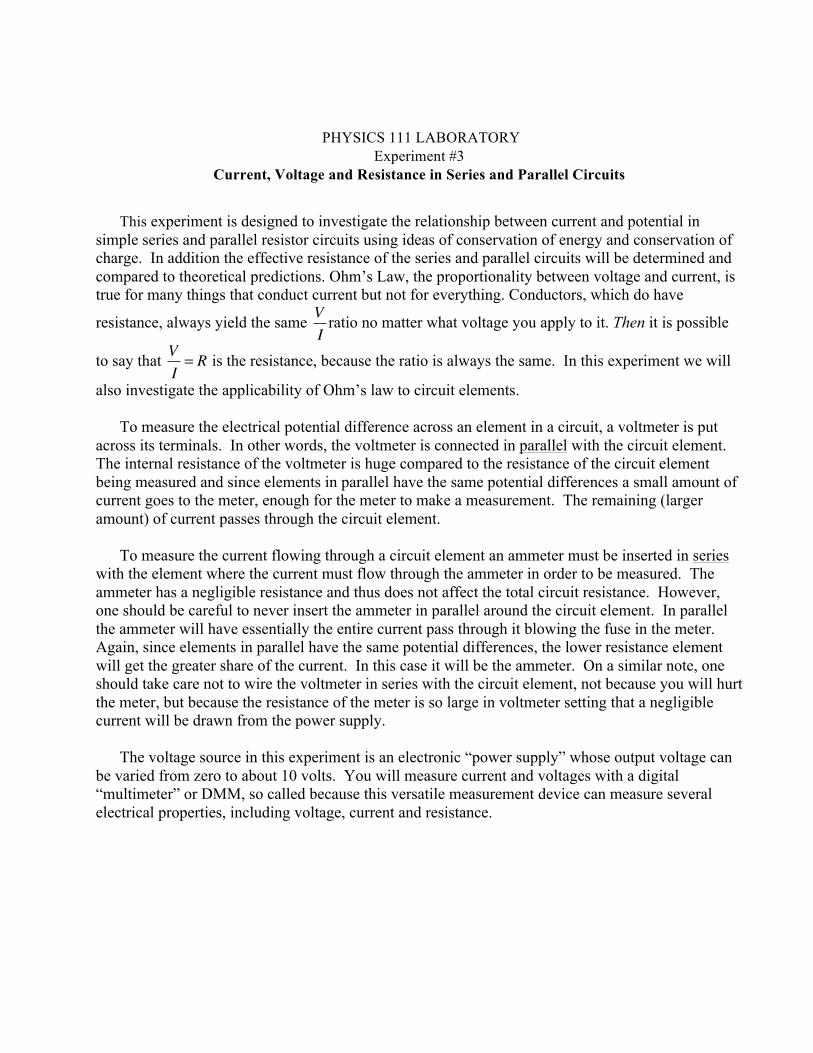
• For each resistor you have, wire it in a circuit as shown in Figure 1. • Select 10 potential differences and measure the corresponding potential differences
across the resistor and the current through the resistor as measured on each of the DMM’s.
• Plot the potential difference versus the current for each resistor you have on the same graph.
• If the data are linear, fit the data with a straight line and determine the experimental values of the resistance for each resistor.
• How do these values compare to the values you measured? • Does each of your resistors follow Ohm’s law?
Figure 1: Wiring diagram for a single resistor connected to a battery VB. The voltmeter is placed in parallel around the resistor R to measure the potential difference across the resistor VR while the ammeter A is placed in series to measure the current I that flows through the resistor.
2. Series Circuit
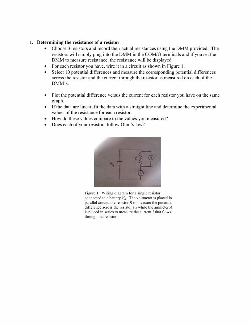
• Choose two resistors and wire the series circuit as shown in Figure 2. You will need 3DMM’s for this part of the experiment.
• Set a potential difference
�
VB = 2V and determine the current through each resistor at a point before
�
R1, between
�
R1 and
�
R2 , and after
�
R2 by using the DMM in ammeter mode. What can you conclude about the current flow through each resistor in a series circuit?
• Next for VB = 4V , 6V , 8V , and 10V , measure the corresponding current through the circuit for each of these potential differences. In addition measure the potential difference across each of these resistors.
• Make a plot of
�
VB , VR1, and VR2
versus Itotal on the same graph. • For a given value of the current, what can you conclude about the potential difference
across each resistor compared to the potential difference of the battery? • From your plot, experimentally what can you conclude about the effective circuit
resistance? • Does your result agree with theory?
Figure 2: Wiring diagram for two resistors wired in series and connected to a battery VB. Each voltmeter is placed in parallel around the resistor R to measure the potential difference across the resistor VR while the ammeter A is placed in series to measure the current I that flows through the resistor combination.
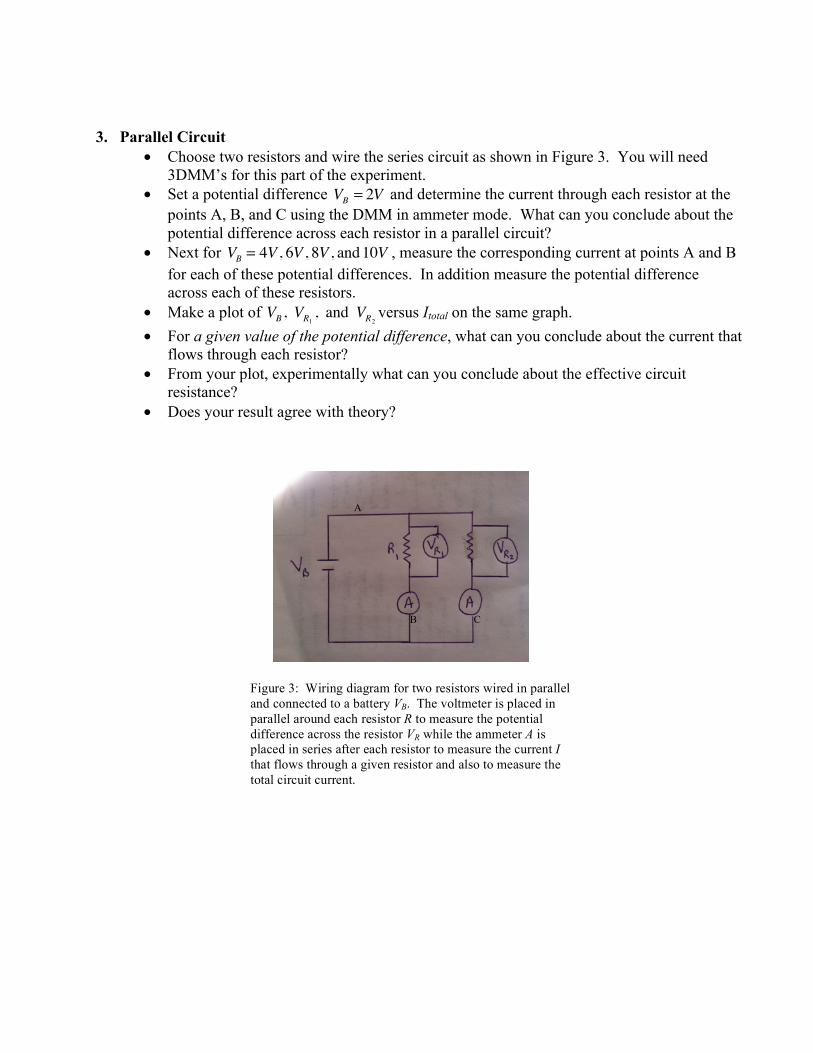
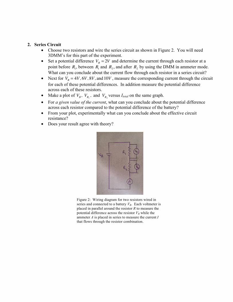
3. Parallel Circuit • Choose two resistors and wire the series circuit as shown in Figure 3. You will need
3DMM’s for this part of the experiment. • Set a potential difference
�
VB = 2V and determine the current through each resistor at the points A, B, and C using the DMM in ammeter mode. What can you conclude about the potential difference across each resistor in a parallel circuit?
• Next for VB = 4V , 6V , 8V , and 10V , measure the corresponding current at points A and B for each of these potential differences. In addition measure the potential difference across each of these resistors.
• Make a plot of
�
VB , VR1, and VR2
versus Itotal on the same graph. • For a given value of the potential difference, what can you conclude about the current that
flows through each resistor? • From your plot, experimentally what can you conclude about the effective circuit
resistance? • Does your result agree with theory?
Figure 3: Wiring diagram for two resistors wired in parallel and connected to a battery VB. The voltmeter is placed in parallel around each resistor R to measure the potential difference across the resistor VR while the ammeter A is placed in series after each resistor to measure the current I that flows through a given resistor and also to measure the total circuit current.
A
B C
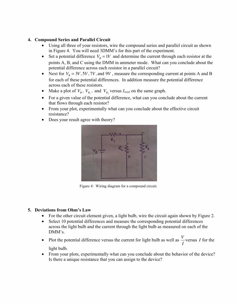
4. Compound Series and Parallel Circuit • Using all three of your resistors, wire the compound series and parallel circuit as shown
in Figure 4. You will need 3DMM’s for this part of the experiment. • Set a potential difference VB = 1V and determine the current through each resistor at the
points A, B, and C using the DMM in ammeter mode. What can you conclude about the potential difference across each resistor in a parallel circuit?
• Next for VB = 3V , 5V , 7V , and 9V , measure the corresponding current at points A and B for each of these potential differences. In addition measure the potential difference across each of these resistors.
• Make a plot of
�
VB , VR1, and VR2
versus Itotal on the same graph. • For a given value of the potential difference, what can you conclude about the current
that flows through each resistor? • From your plot, experimentally what can you conclude about the effective circuit
resistance? • Does your result agree with theory?
5. Deviations from Ohm’s Law • For the other circuit element given, a light bulb, wire the circuit again shown by Figure 2. • Select 10 potential differences and measure the corresponding potential differences
across the light bulb and the current through the light bulb as measured on each of the DMM’s.
• Plot the potential difference versus the current for light bulb as well as
�
VI
versus
�
I for the
light bulb. • From your plots, experimentally what can you conclude about the behavior of the device?
Is there a unique resistance that you can assign to the device?
Figure 4: Wiring diagram for a compound circuit.
A
B C