Embed Size (px)
Citation preview

Longitudinal and vertical focusing with a field gradient spiral inflector
A. H. Barnard ,* J. I. Broodryk, J. L. Conradie, J. G. de Villiers , J. P. Mira ,F. Nemulodi , and R. Thomae
iThemba Laboratory for Accelerator Based Sciences, Faure Road, Cape Town 7600, South Africa
(Received 12 October 2020; accepted 19 January 2021; published 5 February 2021)
Traditional spiral inflectors of the Belmont-Pabot type are commonly used for axial injection of externalion beams into cyclotrons. These inflectors are designed to control the trajectory of the central path,and do not actively focus the beam in the vertical and longitudinal directions. This can introduce effectssuch as a large vertical divergence and a debunching longitudinal spread, making it difficult to match theinjection line emittance to the cyclotron acceptance. In an attempt to overcome this, some recent inflectorshave started incorporating electrodes specially shaped to produce field gradients along the central path,thereby influencing the inflector optics. This method has shown some success, and at iThemba LABS aninflector was built exhibiting good vertical focusing. However, it performed poorly longitudinally, worsethan traditional spiral inflectors. In this article a generalized field gradient spiral inflector design ispresented, based on a mathematical description of all possible first-order field gradients along the centralpath. Such a design is numerically optimized to simultaneously focus longitudinally and vertically.Experimental studies of this design show a 60% improvement in overall current extracted from thecyclotron.
DOI: 10.1103/PhysRevAccelBeams.24.023501
I. INTRODUCTION
Introduced by Belmont and Pabot in 1966, traditionalspiral inflectors are used to inject external axial beams intothe midplane of a cyclotron. This is done by applying anelectric field perpendicular to the central beam path in thepresence of the main magnetic field, in such a way that thebeam travels in a spiraling motion and is eventually bentfrom its axial direction to the central acceleration plane [1].Unfortunately, spiral inflectors can defocus and spread
out the beam, so that it is poorly matched to the cyclotronacceptance [2]. The transverse and longitudinal 2D emit-tances are also not necessarily conserved anymore, due tothe complex coupling of motion in all directions. The full6D emittance is conserved, but this does not in general limitthe size of the projected 2D emittances [3].An example of this beam degradation is the large vertical
divergence typically found at the inflector exit, as shown inFig. 1, which has been observed to lead to beam loss in theinner part of the cyclotron. In the Solid Pole Cyclotron 2(SPC2) at iThemba LABS, numerical modeling of thevertical motion produced by the Belmont-Pabot inflector
shows a beam loss of 30%–40% even before reaching thefirst acceleration gap, due to vertical losses on a collimator.To address this problem of vertical defocusing, one
possible solution is to add a focusing element such as anelectric or magnetic quadrupole immediately downstreamof the inflector [4]. But this is often difficult to do, sincethere is very limited space available in the central regionand it also does not address the emittance blowup due to thecoupled motion inside the inflector. Another method is toincorporate the focusing into the inflector itself, by intro-ducing electric field gradients along the central trajectory.One such design, developed at Dubna [2], gives theelectrodes a V shape in the transverse plane, as shownin Fig. 2, and is similar in nature to the vertical focusingproduced in a spherical electrostatic bend. Another design,from Sumitomo Heavy Industries [5], uses angled electro-des in the transverse plane, as shown in Fig. 2, and alsomodifies the entrance and exit edge angles to generatequadrupoles in the fringe field region.Recently at iThemba LABS a new inflector was devel-
oped that also utilized angled electrodes and edge effects toobtain very good vertical focusing, resulting in an exper-imentally measured 100% improvement in the extractedcurrent from the cyclotron, whenever the buncher was notused [6]. However, this inflector also introduced anunwanted longitudinal spread, which greatly decreasedits time-dependent performance, so that the improvementin transmission dropped to around 20% when the buncherwas activated.
Published by the American Physical Society under the terms ofthe Creative Commons Attribution 4.0 International license.Further distribution of this work must maintain attribution tothe author(s) and the published article’s title, journal citation,and DOI.
PHYSICAL REVIEW ACCELERATORS AND BEAMS 24, 023501 (2021)Editors' Suggestion
2469-9888=21=24(2)=023501(9) 023501-1 Published by the American Physical Society

This focused our attention on the longitudinal influenceof inflectors, a topic that has received less attention in thepast. In spiral inflectors initial transverse displacements atthe inflector entrance can result in final longitudinaldisplacements: ðljxÞ; ðljx0Þ; ðljyÞ; ðljy0Þ ≠ 0. This hasthe effect of longitudinally elongating a bunch of particlesthat all arrive at the inflector at the same time, therebyproducing a debunching effect. This effect is very signifi-cant and TOSCA [7] models of the traditional spiralinflector used at iThemba LABS show a �39° rf phasespread when injected with a typical beam of 90π mmmradtransverse emittance and no momentum spread. This showsthat an inflector should ideally focus both longitudinallyand vertically at the same time.
II. THE SPC2 CYCLOTRONAND C-INFLECTOR
The work described in this article was performed on theSolid Pole Cyclotron 2 (SPC2), aK ¼ 11 injector cyclotronfor the main K ¼ 200 Separated Sector Cyclotron atiThemba LABS. SPC2 is capable of accelerating particlesalong three different orbit trajectories, and heavy ions areinjected into an eight turn orbit geometry using the spiralinflector called inflector-C [8]. For this orbit geometry an rfharmonic number h ¼ 6 is used. In order to distinguishbetween the different inflectors described here, the chrono-logical names C1, C2 and C3 are used. Inflector-C1 is theoriginal Belmont-Pabot design, inflector-C2 is a fieldgradient design producing very strong vertical focusing,
and inflector-C3 is a more general field gradient designcapable of simultaneous vertical and longitudinal focusing.The Belmont-Pabot design parameters for the centraltrajectory in these inflectors are shown in Table I.
III. COORDINATE SYSTEM
To aid in the description of the inflectors, an overview ofthe optical ður; hr; sÞ spiral inflector coordinate system isgiven here, as shown in Fig. 3 [9]. The location of thecentral path is indicated by x0ðsÞwhere s is the path length,and the direction of motion is given by the unit vectors ¼ x0
0 where the dash indicates differentiation with respectto the path length. At every point along the path a transverseður; hrÞ plane is located perpendicular to s, so that urpoints along the direction of the electric field, and hr isperpendicular to the field, so that ður; hr; sÞ forms aright-handed system. The location of a point in space isgiven by
xður; hr; sÞ ¼ x0ðsÞ þ ururðsÞ þ hrhrðsÞ: ð1Þ
The use of the “r” subscript is for historical reasons, todistinguish this rotated frame aligned with the electric fieldfrom an unrotated ðu; h; sÞ system where h is alwayshorizontal. During the design of the electrodes the rotatedreference frame is used since it provides an easier way ofdescribing the electric field and its gradients. On the otherhand, when calculating the transfer matrices the unrotatedframe is used, since it aligns with the horizontal and verticaldirections. In order to work properly with the coordinatesystem, it is useful to describe the motion of the ortho-normal ður; hr; sÞ frame by a rotation around a curvaturevector κðsÞ:
FIG. 2. Electrode cross sections in the transverse plane: TheDubna V shape (left) and the Sumitomo angled electrodes (right).
FIG. 1. A traditional spiral inflector (left) showing large verticaldivergence, and a field gradient spiral inflector (right) with muchimproved vertical behavior.
TABLE I. Belmont-Pabot parameters used by the C-inflectors.
Magnetic bending radius Rm 4.9 cmElectric bending radius A 6.0 cmTilt parameter k0 0.38
FIG. 3. Optical coordinate system around the central path (left).Electrode cross section of a Belmont-Pabot inflector in thetransverse ður; hrÞ plane (right).
A. H. BARNARD et al. PHYS. REV. ACCEL. BEAMS 24, 023501 (2021)
023501-2

u0r ¼ κshr − κhs ð2aÞ
h0r ¼ κus − κsur ð2bÞ
s0 ¼ κhur − κuhr: ð2cÞ
The basis vectors of the ður; hr; sÞ coordinate system areindicated by
b1 ¼∂x∂ur ¼ ur ð3aÞ
b2 ¼∂x∂hr ¼ hr ð3bÞ
b3 ¼∂x∂s ¼ sð1 − urκh þ hrκuÞ þ κsðurhr − hrurÞ: ð3cÞ
This shows that the basis vectors are not always orthogonal,except on the central trajectory itself. The dual basisvectors, indicated by bi, are defined according to
bi · bj ¼ δij ð4Þ
which means
b1 ¼ ur þhrκs
1 − urκh þ hrκus ð5aÞ
b2 ¼ hr −urκs
1 − urκh þ hrκus ð5bÞ
b3 ¼ 1
1 − urκh þ hrκus: ð5cÞ
All of these terms are known analytically for a traditionalBelmont-Pabot inflector.
IV. INFLECTOR WITH VERTICAL FOCUSING
The C2-inflector was developed at iThemba LABS for theexpress purpose of vertical focusing [6]. It used electrodesangled towards each other, similar to the Sumitomo design inFig. 2, as well as angled entrance and exit electrode edges, toproduce quadrupole fields of the type ∂Eur=∂hr, ∂Ehr=∂ur.The results of experimental testing of the C2-inflector
are shown in Fig. 4. With the buncher turned off, theinflector performed very well, roughly doubling theextracted current. With the buncher turned on, the beamis still injected very well, but the extraction sees a largedrop in performance.This decrease in performance is thought to be the result
of a large longitudinal spread introduced by C2, whichtranslates into a large energy spread during the accelerationprocess, resulting in a broad beam with poor extraction
efficiency. When C2 is injected with a very short bunch, ofnegligible longitudinal and momentum spread, comingfrom a typical beam of 90π mmmrad transverse emittance,TOSCA models show a severe �13 mm longitudinalspread (�90° rf phase) at the first acceleration gap. Thisdebunching effect is made worse by the high harmonicnumber (h ¼ 6) rf frequency used by SPC2, which reducesthe rf phase acceptance.Attempts at improving the longitudinal spread of a C2-
type design have proven unsuccessful. Extra degrees ofdesign freedom were required, and so it was necessary toconsider all possible field gradients in more detail.
V. FIRST ORDER OPTICS: ELECTRICFIELD GRADIENTS
The first order optics of a system can be determined byknowing the electric and magnetic fields on the centralpath, as well as their first order gradients. In a traditionalBelmont-Pabot inflector the magnetic gradient is assumedto be zero, and the electrodes are placed parallel to eachother, in order to keep the electric field as uniform aspossible. There are however several ways of intentionallycreating electric gradients by shaping the electrodes.For illustrative purposes the 3D curvature of the centraltrajectory can be neglected, and the electric field
100 200 300 400 500
Cyclotron radius (mm)
100
120
140
160
180
200
220
240
Tra
nsm
issi
on r
elat
ive
to C
1 (%
)
Injection Extraction
20Ne3+ Buncher On4He2+ Buncher On20Ne3+ Buncher On12C2+ Buncher On20Ne3+ Buncher Off12C2+ Buncher Off
FIG. 4. Experimental transmission through SPC2 when usingthe vertically focusing C2-inflector, as a percentage of thestandard C1-inflector transmission. Solid lines are with thebuncher and dotted lines are without the buncher.
LONGITUDINAL AND VERTICAL FOCUSING WITH … PHYS. REV. ACCEL. BEAMS 24, 023501 (2021)
023501-3
approximated as purely 2D in the transverse plane. Anormal quadrupole field can then be created by usinghyperbola-shaped electrodes, as shown on the left in Fig. 5:
∂Eur
∂hr −∂Ehr
∂ur ¼ 0: ð6Þ
Alternatively a skew quadrupole can be created by usingconcentric electrodes, as shown on the right in Fig. 5:
∂Eur
∂ur þ ∂Ehr
∂hr ¼ 0: ð7Þ
Fringe fields at the electrode edges affect the inflector inimportant ways. At the entrance and exit the fringe fieldhas large gradients, which can be harnessed to producequadrupoles along the beam path by reorienting theelectrode face. When the edge is cut at an angle to thebeam path in the ðhr; sÞ plane, as shown on the left inFig. 6, a normal quadrupole is produced in the fringe fieldregion. The edge can also be cut at an angle in the ður; sÞplane, shown on the right in Fig. 6. This produces fieldgradients, but it also violates the design condition of ϕ ¼ 0on the central path. This is however a situation that occursfrequently in actual inflectors, where the electrodes are
sometimes shortened to compensate for the fringe field’sbending of the central path.Fringe fields are also present along the sides of the
inflector, at the �hr edges, and these fields may producequadrupoles on the central path. This effect is exploited bywork at Dubna [10], where the positive and negativeelectrodes are kept parallel, but given different widths,producing skew quadrupoles on the central path. In thedesign of the C2 and C3 inflectors presented here, theelectrodes lie on equipotential surfaces, and the fringefields are regarded as unwanted side effects introduced bythe finite electrode width. These fringe quadrupoles can bereduced by using electrodes with a sufficiently large width-to-gap ratio.
VI. A MATHEMATICAL DESCRIPTION
In order to combine these methods of gradient creation, itis useful to try to find themost general format of the electricalpotential in the region close to the central path, and tocalculate the electric fields and field gradients from thispotential. Obtaining an analytic expression for the electricfields in thiswayhas been suggested in [11], but the approachhere is more general, in that the full tensor expression for theLaplacian is used. This is advisable for higher ordersolutions, since the curvilinear ður; hr; sÞ coordinate systemis not locally orthogonal, except on the central path. In such ageneral case the Laplacian becomes [12]:
∇2ϕ ¼ 1ffiffiffig
pXi
∂∂ui
� ffiffiffig
p Xj
∂ϕ∂uj g
ij
�¼ 0; ð8Þ
where u1, u2, u3 refer to the coordinate values ur; hr; srespectively. Thematrix gij is the inverse of themetricmatrixgij and g refers to the determinant of the metric matrix:
gij ¼ bi · bj ¼
264
1 0 −hrκs0 1 urκs
−hrκs urκs K
375; ð9Þ
where
K ¼ κ2sðu2r þ h2rÞ þ ð1 − urκh þ hrκuÞ2: ð10Þ
The complicated expression for the Laplacian reduces to asimpler form in the region close to the central path whereur; hr → 0. Representing all the first and higher order termsof ur and hr by Oður; hrÞ, we see
∂2ϕ
∂u2r þ∂2ϕ
∂h2r þ∂2ϕ
∂s2 þ κu∂ϕ∂hr − κh
∂ϕ∂ur ¼ Oður; hrÞ: ð11Þ
Note that by designϕ ¼ 0 on the central path, soϕ00 is first orhigher order in ur, hr and can also be grouped insideOður; hrÞ. Since we are only interested in the first order
FIG. 5. Creating normal quadrupole field gradients by usinghyperbolic electrodes (left), and creating skew quadrupole fieldgradients by using cylindrical electrodes (right). The left-handmethod is similar to the angled electrodes used by Sumitomo andby C2, while the right-hand method is similar to the V-shapedDubna design shown in Fig. 2.
FIG. 6. Creating transverse field gradients in the fringe fieldregion by cutting both electrodes in the ðhr; sÞ plane (left) and inthe ður; sÞ plane (right).
A. H. BARNARD et al. PHYS. REV. ACCEL. BEAMS 24, 023501 (2021)
023501-4
optics, which is determined by the first order electric fields, asecond order expression for ϕ can be substituted into thisequation. Keeping only the lowest order terms in ur, hr wethen obtain
∂2ϕ
∂u2r þ∂2ϕ
∂h2r þ s0 · E0 ¼ 0: ð12Þ
At a given s, this becomes the 2D Poisson equation in theður; hrÞplane,with a constant forcing term.Thepotential andthe electric field on the central path are known, giving thefollowing format as the most general expression for thepotential:
ϕ¼−urE0−Q1E0
u2r −h2r2
−Q2E0urhr−u2r2s0 ·E0; ð13Þ
whereE0 and s0 ·E0 are known functions of the central path,so that the quadrupole parameters Q1ðsÞ and Q2ðsÞ are theonly free terms, and can be selected by the inflector designer.TheQ1 term corresponds to the spherical electrodes in Fig. 5,and theQ2 terms correspond to the angled electrodes. Thesedefinitions of Q1 and Q2 have been selected so that atraditional Belmont-Pabot inflector with its parallel electro-des should have Q1 ¼ Q2 ¼ 0. Note that in our previouspublication [6] on the C2-inflector a single quadrupoleparameter QðsÞ was used to describe the angled electrodes,which corresponds to Q ¼ −Q2 in this work.A desired potential can then be physically obtained by
constructing the inflector electrodes so they lie on equi-potential surfaces. Since Eq. (13) only holds at small valuesof ur, hr it is not applicable to the electrode surfaces at theentrance and exit, and we limit its use to the interior of theinflector. Care should also be taken that Q1ðsÞ and Q2ðsÞvary smoothly, since their derivatives contribute to theOður; hrÞ terms, and thereby reduce the ður; hrÞ regionwithin which Oður; hrÞ may be neglected.The electric field is obtained from the gradient of the
potential:
E ¼ −∇ϕ ¼ −Xi
∂ϕ∂ui b
i: ð14Þ
When writing the electric field in component form,
E ¼ Euruþ Ehrhþ Ess; ð15Þ
it is found that the components are given, to first order in ur,hr, by
Eur ¼ E0 þ urðQ1E0 þ s0 ·E0Þ þ hrQ2E0 ð16aÞ
Ehr ¼ urQ2E0 − hrQ1E0 ð16bÞ
Es ¼ urE00 þ hrκsE0: ð16cÞ
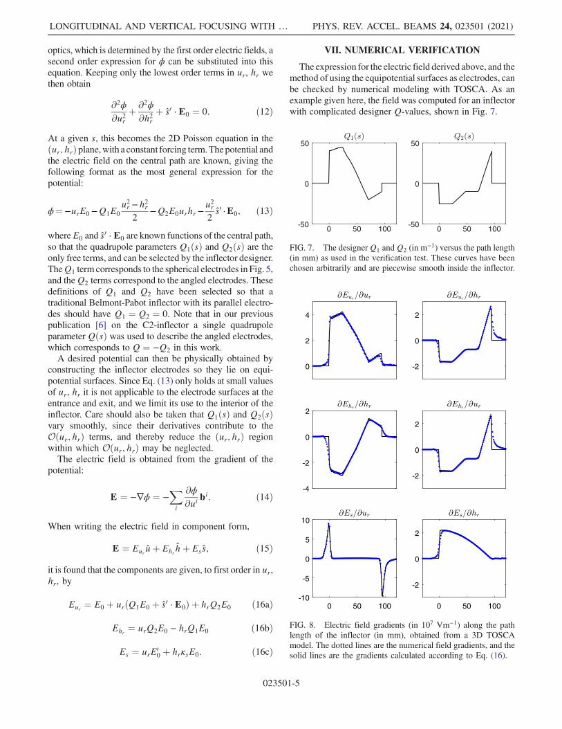
VII. NUMERICAL VERIFICATION
The expression for the electric field derived above, and themethod of using the equipotential surfaces as electrodes, canbe checked by numerical modeling with TOSCA. As anexample given here, the field was computed for an inflectorwith complicated designer Q-values, shown in Fig. 7.
0 50 100-50
0
50
0 50 100-50
0
50
FIG. 7. The designerQ1 andQ2 (in m−1) versus the path length(in mm) as used in the verification test. These curves have beenchosen arbitrarily and are piecewise smooth inside the inflector.
-2
0
2
0
2
4
-2
0
2
-4
-2
0
2
0 50 100
-2
0
2
0 50 100-10
-5
0
5
10
FIG. 8. Electric field gradients (in 107 Vm−1) along the pathlength of the inflector (in mm), obtained from a 3D TOSCAmodel. The dotted lines are the numerical field gradients, and thesolid lines are the gradients calculated according to Eq. (16).
LONGITUDINAL AND VERTICAL FOCUSING WITH … PHYS. REV. ACCEL. BEAMS 24, 023501 (2021)
023501-5

The field gradients are shown in Fig. 8, where thenumerical values from TOSCA are compared to the valuescalculated from Eq. (16), using the TOSCAvalue for E0ðsÞand the designer Q-values. There is good agreement, andthe only noticeable discrepancies are at the inflectorentrance and exit, where the Q-values make discontinuousjumps.In this test an electrode width of 20 mm and a nominal
electrode gap of 6 mm were used, which provides asufficient width-to-gap ratio for ignoring the fringe fieldsalong the �hr edges. Furthermore, the design does notcontain any entrance and exit edge angles (β ¼ γ ¼ 0 inFig. 6). When edge angles are included, or when the fringefields play a significant role, the electric field equation isfound to remain valid around the zero-potential line, butwith modified values of Q1 and Q2.
VIII. OPTIMIZATION PROCEDURE
The first order inflector optics is controlled by selectingappropriate field gradient parameters: Q1ðsÞ; Q2ðsÞ and theentrance and exit face angles β1 and β2. The dependence ofthe inflector’s transfer function on the field gradients [writethis as RðQ1; Q2; β1; β2Þ, where R is the transfer function]is computed numerically. This is performed by a MATLAB
program that makes use of a limited number of precalcu-lated 3D electric field solutions obtained with TOSCA, andscaling and extrapolating them linearly to obtain estimatesof the electric fields for various inflector geometries at runtime, as described in more detail in [6]. Ray tracing isemployed, starting at a point well upstream of the inflectorand ending at the first acceleration gap. The magnetic fieldis based on a TOSCAmodel of the full yoke geometry [13].The program is able to compute a transfer matrix by meansof ray tracing within a few seconds, whereas the fullTOSCA-based process would take at least an hour.To perform the optimization, Q1ðsÞ; Q2ðsÞ had to be
discretized, and they were represented by piecewise linearfunctions. As a shorthand notation, we write the end pointsof these piecewise functions with Qij ¼ QiðsjÞ wherej ¼ 1, 2, 3. A finer discretization can be used in futurework, but having three values per function is adequate forproducing a rough doublet or a triplet shape. The values ofthe gradient parameters were then selected by numericallyoptimizing the transfer matrix,
RðQ11; Q12; Q13; Q21; Q22; Q23; β1; β2Þ;
with respect to some scoring function corresponding to thedesired focusing qualities. Various different optimizationmethods were tried, but in the end a randomized samplingto find promising starting points was followed by a steepestdescent method to find the local optima. Each electrodesurface also had to be evaluated to make sure it had aminimum electrode gap, and did not have a shape that isvery difficult to construct.
IX. INFLECTOR WITH LONGITUDINAL ANDVERTICAL FOCUSING
Ideally the inflector should match the injection lineemittance to the accelerator acceptance. In the case ofthe SPC2 however, neither of these properties was knownwith great certainty. So instead of attempting to match theemittance to the acceptance, it was decided to aim for aninflector design which results in a beam with smallervertical emittance and a shorter longitudinal spread thanthe original C1 inflector. The input beam for this optimi-zation task was assumed to have a 3 mm × 30 mradelliptical transverse profile and a 0.5% momentum spread.From the simulations it was found that a design withvertical emittance 20% less than C1, and longitudinalspread 45% less than C1 was obtainable. If accurateinformation about the SPC2 acceptance had been availablethen a better informed design could perhaps have beenfound, but the aim here was mainly to demonstrate thecapability of simultaneous vertical and longitudinal focus-ing. The simulated 2D phase space profiles of all theinflectors are shown in Fig. 9 and Table II provides acomparison of their performance.The Q-values for the inflectors, as obtained from 3D
TOSCA models, are shown in Fig. 10. In accordance with
-10 0 10-100
0
100
u' (
mra
d)
C1
-2 0 2
-100
0
100
h' (
mra
d)
-10 0 10
-0.5
0
0.5
(%
)
-10 0 10
u (mm)
C2
-2 0 2
h (mm)
-10 0 10
-10 0 10
C3
-2 0 2
-10 0 10
FIG. 9. Phase-space plots of the beam at the first accelerationgap for inflectors C1 (left column), C2 (middle column) and C3(right column). The top row is vertical ðu; u0Þ space, the middlerow is horizontal ðh; h0Þ space and the bottom row is longitudinalðl; δÞ space. The C2-inflector has greatly improved verticalbehavior compared to the original C1 inflector, but a muchlarger longitudinal spread. The C3 inflector has moderatelyimproved vertical behavior compared to C1 as well as a smallerlongitudinal spread.
A. H. BARNARD et al. PHYS. REV. ACCEL. BEAMS 24, 023501 (2021)
023501-6

expectations both Q1 and Q2 are very small for thetraditional Belmont-Pabot inflector C1. The C2-inflectorhas been designed to have a large value of Q2, and this isobserved, especially near the entrance and exit, where βcontributes. The C3-design is the only inflector incorpo-rating both Q1 and Q2.During the design process of C3 it was found that
excessive Q2 had a detrimental effect on the longitudinalbehavior, and for this reason the entrance and exit angleswere set to zero, β1 ¼ β2 ¼ 0, while the required Q2 wasobtained by shaping only the internal part of the inflector. Itis however possible that a more optimal design exists,which includes the use of β1 and β2.The transfer matrices R of the inflectors are shown in
Tables III–V. The matrix R gives the transfer functionbetween ðu; u0; h; h0;l; δÞ1 as measured 9 cm upstream ofthe inflector, and ðu; u0; h; h0;l; δÞ2 at the first accelerationgap 6 cm downstream of the inflector. The unrotatedcoordinates ðu; h; sÞ are used here, since the final u iscompletely vertical, and h horizontal, making it easier tointerpret the results. The starting point of the computationwas chosen to be in a region where the magnetic field isnegligible. This means the rotational effect on the beam,due to the growing solenoidal magnetic field when enteringthe cyclotron pole gap, is fully included in R. This effectwas found to have a significant influence on the optics.The transfer matrices are symplectic, with small errors(maximum error is 0.03) when computing the symplecticcondition Ω ¼ RTΩR, indicating that the numerical
computations are reasonably accurate. The units ofðu; h;lÞ are in mm, and ðu0; h0; δÞ are in mrad. In otherwords, δ is in units of 0.1% (this is required for R to besymplectic).The magnitudes of the vertical terms, u2 and u02, are
described by the first two rows of R and mostly follow thesequence C1 > C3 > C2. This is especially the case forthose values corresponding to the influence of ðh; h0Þ1 onðu; u0Þ2, as well as for the dispersion termsR16 and R26. Thevalues corresponding to the influence of ðu; u0Þ1 on ðu; u0Þ2do not follow the same pattern, but are much smaller. Theresulting effect, as shown by the phase-space plots ofFig. 9, is that C2 has the best vertical performance,followed by C3 and then C1.The magnitudes of the longitudinal terms, l2 and δ2, are
described by the last two rows of R. The coupling betweenthe transverse ðu; u0; h; h0Þ1 space and the longitudinalposition l2 is represented by the terms R51, R52, R53
and R54. The general pattern observed in the magnitude ofthese terms is that C2 > C1 > C3. This is particularly truefor R51 where the C3 term is much smaller than the others,and the R53 term where C2 is much greater than the others.In this fashion the C3-inflector design is capable of limitingthe l2-spread due to the transverse-longitudinal coupling.The behavior in the longitudinal ðl; δÞ-subspace is
described by the 2 × 2 matrix in the bottom right-handcorner of R:
TABLE II. Beam parameters at the first acceleration gap ascalculated using TOSCA, based on a 3 mm × 30 mrad beam with0.5% momentum spread. The emittances are percentages of theincoming beam.
C1 C2 C3
Vertical emittance 145 105 120Vertical half width (mm) 8.9 2.9 7.0Horizontal emittance 145 130 120Horizontal half width (mm) 3.0 1.5 2.0Longitudinal half width (mm) 5.5 12.9 3.1rf phase spread (degrees) �39 �90 �22
0 50-50
0
50C1
0 50-100
0
100C2
0 50-50
0
50C3
FIG. 10. Plot of the numerically measured gradient parametersQ1 (dashed line) and Q2 (solid line) versus the path length (inmm) along the inflectors. Note that the C2 graph has a differentvertical scale.
TABLE III. Transfer matrix R of C1 (jRj ¼ 1.00).
−1.3078 −0.0216 −2.1882 −0.2905 0 −0.2462−10.951 −0.2732 −21.255 −3.2250 0 −1.99850.8273 0.0470 −0.3371 −0.0648 0 −0.0166−2.3343 0.9307 −3.7095 −1.0723 0 −1.59821.4403 0.0834 0.3830 0.1273 1 0.1793−0.0027 −0.0015 0.0276 0.0031 0 1.0016
TABLE IV. Transfer matrix R of C2 (jRj ¼ 1.02).
−0.3896 −0.1009 −0.4583 −0.0645 0 −0.08306.5872 −0.3761 −0.7189 −0.5261 0 −0.19570.0830 −0.0119 0.1719 0.0532 0 −0.10835.7389 1.4438 −28.173 −3.9187 0 −1.1680−1.1539 −0.1600 3.2106 −0.5152 1 0.0914−0.0105 −0.0019 0.0217 0.0020 0 1.0012
TABLE V. Transfer matrix R of C3 (jRj ¼ 1.00).
−0.2892 0.0156 −1.9882 −0.2617 0 −0.1862−2.0699 −0.2359 −11.574 −1.9768 0 −1.17930.4382 0.0123 −0.3062 −0.0456 0 −0.055511.271 2.3691 −6.1017 −1.2424 0 −1.60120.1208 −0.0490 −0.3455 0.0546 1 0.15610.0152 0.0034 −0.0162 −0.0017 0 0.9961
LONGITUDINAL AND VERTICAL FOCUSING WITH … PHYS. REV. ACCEL. BEAMS 24, 023501 (2021)
023501-7

�R55 R56
R65 R66
�¼
�1 R56
0 1
�: ð17Þ
This matrix is equivalent to a drift space where R56
represents the optical path length. The effect of R56 maytherefore be regarded as shifting the location of the focalpoint of the buncher, which will introduce an l2-spread atthe original focal point. This can however be compensatedfor by adjusting the focal length of the buncher (by tuningthe buncher voltage during cyclotron operation) so thatthe focal point remains at its original location, and nol2-spread is introduced by the inflector due to R56.To provide a general sense of the physical inflector
shapes, 3D images of their designs are shown in Fig. 11.
X. EXPERIMENTAL RESULTS
The C3 inflector was constructed out of copper using acomputer numerical control (CNC) mill, requiring 64 hoursof machining time, and it was tested in the SPC2 cyclotron.Experiments were conducted to determine the transmissionusing all three inflectors C1, C2 and C3, where the beamcurrent was measured throughout the cyclotron, and com-pared to the current on the Faraday cup immediatelyupstream of the cyclotron to obtain the transmission.The C2 and C3 transmission was then normalized as afraction of the C1 transmission, to obtain the relativetransmission which indicates how the new C2 and C3inflectors perform compared to the original C1. Theexperimental results without the buncher activated areshown in Fig. 12. It indicates a relative transmission ofabout 120% for C3 and about 200% for C2. This is mostlydue to the very good vertical injection of C2, but also showsthat C3 is a vertical improvement over the original inflector.The performance with a buncher is shown in Fig. 13. For
both C2 and C3 the relative transmission within thecyclotron is roughly 150%, but at the extraction thisimprovement largely disappears for C2 while it increasesfor C3. Activating the buncher decreases the relativetransmission of C2 (originally 200%), but increases thatof C3 (originally 120%). This can be explained by C2
having worse longitudinal performance than C1, while C3is an improvement on C1.The good longitudinal properties of C3 are supported by
Fig. 14, where the influence of the buncher is shown. Thetransmission through the cyclotron is plotted as a functionof the rf phase offset between the Dee voltage and thebuncher voltage. When the buncher is far away from itsoptimal phase, the transmission is about half of the no-buncher current, which is close to the expected theoreticalvalue for a first harmonic buncher. At the optimal phaseoffset, C2 produces an improvement in transmission of
FIG. 11. 3D models of the C-inflectors, as they were manu-factured: C1 (left), C2 (middle) and C3 (right). C1 has parallelelectrodes in the ður; hrÞ plane, C2 has straight nonparallel lines,and C3 has quadratic lines. For C2 the entrance and exit edges arenot perpendicular to the central path.
100 200 300 400 500
Cyclotron radius (mm)
100
120
140
160
180
200
220
240
Tra
nsm
issi
on r
elat
ive
to C
1 (%
)
Injection Extraction
C2 20Ne3+
C2 12C2+
C3 20Ne3+
C3 12C2+
FIG. 12. The transmission of C2 and C3, as a percentage of C1transmission, without a buncher. C2 performs very well, since itwas optimized for vertical focusing only, and C3 shows a smallimprovement.
100 200 300 400 500
Cyclotron radius (mm)
100
120
140
160
180
200
220
240
Tra
nsm
issi
on r
elat
ive
to C
1 (%
)
Injection Extraction
C2 20Ne3+
C2 4He2+
C2 20Ne3+
C2 12C2+
C3 20Ne3+
C3 12C2+
FIG. 13. The transmission of C2 and C3, as a percentage of C1transmission, with the buncher active. The relative transmissionof C3 increases when the buncher is activated, while that of C2reduces.
A. H. BARNARD et al. PHYS. REV. ACCEL. BEAMS 24, 023501 (2021)
023501-8

around 2.1 times compared to the no-buncher current, C1improves by 3.8 times, while C3 improves the transmissionby 4.8 times.Since only two sets of independent measurements have
been obtained with C3 so far (six sets for C2), these resultsshould be regarded as patterns, rather than exact numericalvalues. From the C2 experiments it is however clear that allthe measurements follow the overall pattern reasonably well.
XI. CONCLUSION
The work described here shows that the spiral inflectorelectrode can be shaped to simultaneously achieve betterlongitudinal and vertical focusing, thereby substantiallyimproving the spiral inflector performance. Along thecentral path the first order electric field gradients aredetermined by two parameters Q1ðsÞ and Q2ðsÞ, producingquadrupole and skew-quadrupole fields in the transverseplane. These quadrupole parameters dictate the shape of theelectrode surfaces and can be freely selected by theinflector designer to influence the optics.
[1] J. Belmont and J. Pabot, Study of axial injection for theGrenoble cyclotron, IEEE Trans. Nucl. Sci. 13, 191 (1966).
[2] B. Gikal, G. Gulbekian, and I. Ivanenko, Compensation ofthe beam vertical defocusing at the exit of U400 cyclotronspiral inflector, in Proceedings of 21st Russian Particle
Accelerators Conference (RuPAC 2008) (Joint Institute forNuclear Research, Dubna, 2008), https://accelconf.web.cern.ch/r08/papers/TUAPH12.pdf.
[3] K. L. Brown and R. Servranckx, Cross plane coupling andits effect on projected emittance, Part. Accel. 36, 121(1989), https://cds.cern.ch/record/200630/files/p121.pdf.
[4] I. Ivanenko, The methods of compensation of the beamvertical divergence at the exit of spiral inflector incyclotrons, in 21st International Conference on Cyclotronsand Their Applications (Cyclotrons’ 16), Zurich,Switzerland, 2016 (JACOW, Geneva, Switzerland),pp. 221–223.
[5] H. Tsutsui, Report No. JP5606793B2, 2010.[6] A. Barnard, J. Broodryk, J. Conradie, J. De Villiers, J.
Mira, F. Nemulodi, and R. Thomae, Vertical focusing witha field gradient spiral inflector, in Proceedings of the 22ndInternational Conference on Cyclotrons and their Appli-cations (Cyclotrons 19), Cape Town, South Africa, 2019(JACOW, Geneva, Switzerland, 2019), pp. 58–61.
[7] Opera-3D Suite version 17R1, TOSCA electromagneticFEA simulation software (2019).
[8] Z. Du Toit, J. Cornell, A. Müller, J. Delsink, P. Rohwer, W.Van Heerden, J. De Villiers, D. Fourie, S. Burger, P.Celliers et al., Commissioning of the injector cyclotron forpolarized and heavy ions at NAC, in Proceedings of the14th International Cyclotron Conference and TheirApplications (World Scientific Publishing, Singapore,1996), pp. 28–31, ISBN 981022625X, http://accelconf.web.cern.ch/c95/.
[9] L. W. Root, Design of an inflector for the TRIUMFcyclotron, M.Sc. Thesis, University of British Columbia,1972.
[10] V. Smirnov, Central region design in a compact cyclotron,Phys. Part. Nucl. Lett. 16, 34 (2019).
[11] M. Sekiguchi and Y. Shida, Orbit analysis of thespiral inflector for cyclotrons, Technical Report, TokyoUniversity, 1992.
[12] M. R. Spiegel, Schaum’s Outline of Theory and Problems ofVector Analysis and an Introduction to Tensor Analysis(SchaumPub.Co.,NewYork,1974), ISBN:9780070602281.
[13] J. De Villiers, J. Broodryk, J. Conradie, F. Nemulodi,R. Thomae, J. Yang, and T. Zhang, Numerical orbittracking in 3D through the injector cyclotron for heavyions at iThemba LABS, in 21st International Conferenceon Cyclotrons and Their Applications (Cyclotrons’ 16),Zurich, Switzerland (JACOW, Geneva, Switzerland, 2016),pp. 71–74.
-200 -150 -100 -50 0 50 100 150 200
Buncher phase offset (degrees)
0
1
2
3
4
5
Ext
ract
ed C
urr
ent
C1
C2
C3
FIG. 14. Buncher efficiency: the extracted current when thebuncher phase is varied, as a fraction of the no-buncher current.The phase has been normalized so that the buncher performanceis optimal at zero degrees.
LONGITUDINAL AND VERTICAL FOCUSING WITH … PHYS. REV. ACCEL. BEAMS 24, 023501 (2021)
023501-9