Embed Size (px)
Citation preview
Physical Mockups as Interface between Design and Construction: A North-American Example
Pietroforte, R. Department of Civil and Environmental Engineering, Worcester Polytechnic Institute
(email : [email protected]) Tombesi, P.
Faculty of Architecture, Building and Planning, The University of Melbourne (email: [email protected])
Abstract
The growing use of modern construction technologies with different tolerances and installation requirements in buildings has made the reliance on full size mockups essential for examining the various interfaces between design and construction. Over the past ten years, 3D/4D digital models have been introduced and developed to this end, and they are now seen by some as eliminating the need for physical mockups. In this study, based on the on-the-job experiences and project management records of the construction of one very significant building in North America, the authors argue that, notwithstanding the recognized capabilities of digital models, physical mockups are still needed for capturing and eliciting the tacit knowledge that characterizes many construction operations, and which cannot be visualized fully by the digital world. This is because some field conditions are very difficult to foresee and represent; as a consequence, construction workers may not achieve on the ground what seems achievable on design documents. Depending on situations, the process of constructing and successfully completing a mockup is still the essential locus where some (but not all) field conditions can be verified, the outcome of craft-based efforts can be observed and evaluated, and design intents and construction procedures modified accordingly. This argument is developed by illustrating the challenges experienced in the erection and testing of a full size mockup of Simmons Hall ― an architectural award-winning dormitory completed at the Massachusetts Institute of Technology in 2002 ― particularly in terms of constructability and functional requirements. By looking at the relationship between initial designers’ agendas and constructed solutions, and by considering the parameters informing specific project decisions, it will be argued that digital and physical models must be considered complementary tools in the realization of design intents.
Keywords: simulation, constructability, tolerances, coordination, communication
95
1. Introduction
The successful transformation of design intents into physical reality has always been a challenge for the parties involved in a construction project ─ clients, designers, contractors and construction workers. This is because the making of a building results from a process during which different types of knowledge are generated, visualized and communicated among many project participants. In a sequentially phased project, clients’ needs are interpreted and transformed into a set of coordinated working drawings by the architect and her consultants. The contractor then analyzes these documents and predicts their effect by developing a set of construction methods and sequences as well construction time schedules, before the start of site operations. Finally, construction workers deploy their manual capabilities in transforming design and construction plans into physical reality. A large proportion of the knowledge generated and communicated during design and pre-construction activities has an explicit nature (Polanyi 1962). Explicit knowledge can be articulated in symbolic or visual form, such as calculations, drawings and sketches, which can be communicated to and understood by receiving parties. Differently, the knowledge deployed by construction workers is of a tacit nature, in the sense that it cannot be easily visualized or communicated (Polanyi 1962); it can be observed and learned only in action. The challenge of predicting the intended construction outcome can be seen in masonry construction, the history of which is characterized by full-size models of building sections, erected to assess the quality of expected finishes and workmanship before actual construction (King 2001).
More recently, the visualization and communication of design and pre-construction activities have been greatly enhanced by the use of 3D and 4D digital models (Eastman et al 2008; Hartman and Fisher 2007). In addition, CAD\CAM based applications have promised to provide a seamless integration of the supply chain of building parts (Kolarevic 2003; Schodek et al 2005).
In this paper the authors argue that, the enhanced visualization and communication capabilities of digital modeling notwithstanding, the transformation of design into physical reality must still rely on the use of physical mockups.
Design activities are a continuum that extends well beyond the work carried out during the conventionally termed ‘design phase’ of a project. Much additional design is undertaken to realize design intents, when a contractor receives contractual plans and specifications, and develops the shop drawings accordingly. In this activity, which we label ‘design realization’, the interaction of project participants normally requires a different type of support: the construction of a physical model to solicit the additional knowledge needed for completing the design. This critical interface has not received enough attention in the specialized literature, particularly in the U.S.A., the construction practice of which is addressed in this paper. Past contributions, in fact, have focused mostly on the design (i.e., working drawings and specifications) of building parts and their manufacturing, devoting scant attention to their assembly at the construction site.
96
2. Knowledge and the building process
As stated in the opening section, the building process unfolds from expertise that manifests itself in two forms ─ explicit and tacit. According to Nonaka (1991), explicit knowledge can be easily expressed, captured, stored and reused. It can be transmitted as data and is found in books, guidelines and rules of thumb. Differently, tacit knowledge is “highly personal. It is hard to formalize and, therefore, difficult to communicate to others. Tacit knowledge is deeply rooted in action and in the individual’s commitment to a specific context” (Nonaka 1991). Technical or manual skill, intuition and insights are typical examples of tacit knowledge. In construction, for example, a master craftsman with years of experience cannot typically articulate the principles of his know-how as acquired through a period of apprenticeship, i.e., “by working on the job with someone knowledgeable, observing their methods, investing in the tools of that trade, absorbing that culture, practicing under their scrutiny” (Groák 1992). Explicit and tacit knowledge are complementary entities, in that they interact with each other in the creative activities of people. In this case, tacit knowledge is shared through personal interaction.
From this follows that the building process can be thought of as an information process in which the initial building representation is progressively enriched and completed through a process of accretion by bits and pieces that takes place during the, and by means of, interaction of project participants. In the design/engineering phase, this interaction is supported by visual tools such as drawings, sketches and models, which capture and communicate design and engineering content, and which are used to verify/refine this content eventually to reach consensus amongst different stakeholders (Straus and McGrath 1994). The design (architectural and engineering disciplines) and the following pre-construction (e.g., construction sequencing and time scheduling) activities are based mostly on explicit knowledge that is supposed to be predictive (Hartman and Fisher 2007). Design intents and construction plans, in other words, must be deemed to be constructable and feasible. In practice, such a prediction does not fully eliminate the uncertainty of the construction phase, as this is driven by the one-of-a-kind, contingent nature of production in construction. From this perspective, every project is unique. Past positive construction experience may or may not be repeated in future projects, subject to variables such as field conditions and work processes, and the capabilities of available construction workers. Thus, previously successful routines cannot be fully codified into predictive explicit knowledge. During construction, tradesmen generate and apply much tacit knowledge, particularly in joint problem-solving situations generated from the difficulty of fully controlling the actual construction process in advance. In this context, the human interaction of joint problem-solving is supported by another knowledge visualization tool: the physical reality of the building part under construction.
3. The design realization phase of the building process: the case of external facades
The design, engineering and construction of the external facade is one of the most intensive undertakings in a building project, particularly in the case of high-rise or bespoke projects.
97
Technological complexity and the need for integrated engineering capabilities are typical challenges. The facade, in fact, is made up of multiple materials as well as interdependent and often custom-made components, the combined performance of which must be carefully engineered and tested. Moreover, the system requires multiple design and engineering contributions as well as multiple trades for production and assembly ─ all characteristics that call for an extensive and sustained coordination effort. In this regard, the proper visualization of design and engineering content is of great importance for integrating distinct contributions successfully. And, since the overall time schedule of the building envelope is always on the critical path of a project, pre-construction activities are critical for the timely completion of the system.
A most important phase of the pre-construction process consists of the generation, review and approval of shop drawings. In this process, the intents of working drawings ─ i.e., what to build ─ are interpreted and transformed into discrete detailed descriptions of construction process and methods ─ i.e., how to build (DeLapp et al 2004). The importance of this additional design activity has been recognized by other U.S. studies and has been termed ‘design realization’ (Pietroforte 1995, 1997; DeLapp et al 2004). Shop drawings show instructions about the engineering of each component, its fabrication and assembly with other components, and finally the erection of these sub-assemblies. Their approval is the absolute condition for the subsequent fabrication, assembly and erection of the facade components. Shop drawings embody a type of knowledge (e.g., how the cladding is attached to the structure, how it is fabricated, assembled and erected) which is to be found mostly amongst specialty contractors and manufacturers, and rarely amongst architectural designers. Typically generated by multiple parties (e.g., cladding erectors and manufacturers), shop drawings undergo a lengthy review process that aims at verifying their compliance with the intents of the design documents, evaluating and negotiating the proposed engineering solutions, checking the dimensional accuracy and completeness of details, and coordinating the various descriptions of components in order to maintain the functional continuity and aesthetic character of the facade. 2D visualizations and related engineering calculations (these submittals also include material samples and product specifications) are reviewed by the general contractor, the architect of record, and her consultants ─ often geographically dispersed. Comments, corrections or requests for information/clarification are annotated next to details of a given drawing sheet. The lengthy duration of the review process (typically many months), the number of notes (often hundreds in a full set of shop drawings), and the reviews (typically 2 or 3), suggest that the use of paper drawings is not efficient for ensuring real time interaction among generators and reviewers. Only in job meetings does this type of interaction takes place, which then allows for negotiations, compromises and solutions to be reached. Furthermore, 2D drawings are often inadequate in their ability to visualize geometries, assemblies, and technology cum trade interfaces (Pietroforte 1997; Hartman and Fisher 2007). These shortcomings characteristically lead to the possibility of varying interpretations of design and construction intents. For example, 2D representations tend to be stratigraphic rather than volumetric, showing material for more than one level on the same planar space. Thus, as Boehmig (1990) has explained, they do not show the full information needed by the trades when installing the material on the field.
98
4. Digital representation in cladding design realization
Fortunately, in the last ten years, digital representation has become the standard representation medium in the architecture, engineering and construction (AEC) world. Electronic mark-up applications have facilitated the processing of comments and corrections. These capabilities, together with internet transmission, have considerably reduced the duration of the shop drawing process. More recently, 3D-modeling applications have enhanced design/engineering representation and the planning of construction. The use of digital modeling has been somehow spurred by recent development in architectural expression. The unconventional curtain walls and building facades realized by the office of Frank O. Gehry and Partners are a typical example. These walls are curved, sloped or zigzagged, and incorporate unusual combinations of materials. Since the nature of the curves is considered an integral part of the architectural design, the firm has been relying on the use of CATIA, software that constructs curves mathematically and maintains a high level of accuracy. This capability cannot be achieved by traditional CAD packages that approximate curves. Because of its ability to translate numerical instructions into shop tickets, the software defines lines and curves in ways that are usable by fabricators. In this case, enhancing the accuracy of geometries and dimensional fitting of assemblies facilitates the manufacturing of building parts.
In addition, by integrating information distributed over multiple 2D drawings, digital models have improved the coordination of both the interfaces amongst the several work packages that often make up a curtain wall, and the interfaces of the wall with other interacting building parts, i.e., structure, ceiling and partition systems. More recently, 4D-modeling, or time-lapsed series of 3D models, has been used to visualize the construction process and improve the sequencing and scheduling of construction activities. These include staging, the planning of handling, and storage of materials (Hartman and Fischer 2007). 4D-modeling represents a marked improvement on traditional scheduling techniques such as Gant charts and CPM diagrams, the abstract representation of which could create misunderstandings and omissions. This newest system, however, still remains essentially Taylorist and technocratic in its approach, for it envisions a work process (ideally) controlled by skilled workers in the various trades associated with the industry (Applebaum 1982). Possibly as a result, digital scheduling has not yet been able to solve the hurdle of accurately defining the duration of work activities in advance, particularly in the case of new architectural expressions that require non-traditional construction methods and procedures.
In conclusion, the superior visualization capabilities of digital modeling empower the interaction process amongst project participants with more knowledge-generation and communication opportunities than that based only on traditional 2D drawings and time scheduling diagrams. Better interaction increases the probability that design and engineering performance will be satisfactory, and field erection activities undertaken efficiently. However, the constructability of design intents and functional performance are still a prediction that must be verified. Its advancement notwithstanding, digital technology cannot yet capture some aspects of physical reality such as craft-based construction activities or the experience of the “real” object, nor can it simulate physical phenomena such as air or water flows, or the chemical compatibility of materials (Gonchar and Reina 2003). This is the purpose of the physical mockup.
99
5. The mockup as a verification of constructability
Mockup activities signal a shift in the type of visualization strategies used in generating and exchanging knowledge during design realization. A physical object, rather than a graphic or digital display, becomes the context of social and technical interaction during which tacit, rather than explicit, knowledge, is deployed to devise solutions to design and construction problems.
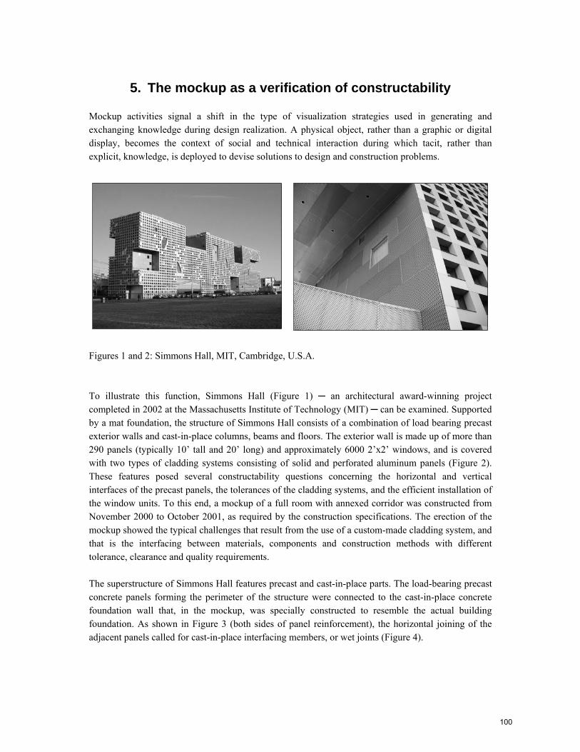
Figures 1 and 2: Simmons Hall, MIT, Cambridge, U.S.A.
To illustrate this function, Simmons Hall (Figure 1) ─ an architectural award-winning project completed in 2002 at the Massachusetts Institute of Technology (MIT) ─ can be examined. Supported by a mat foundation, the structure of Simmons Hall consists of a combination of load bearing precast exterior walls and cast-in-place columns, beams and floors. The exterior wall is made up of more than 290 panels (typically 10’ tall and 20’ long) and approximately 6000 2’x2’ windows, and is covered with two types of cladding systems consisting of solid and perforated aluminum panels (Figure 2). These features posed several constructability questions concerning the horizontal and vertical interfaces of the precast panels, the tolerances of the cladding systems, and the efficient installation of the window units. To this end, a mockup of a full room with annexed corridor was constructed from November 2000 to October 2001, as required by the construction specifications. The erection of the mockup showed the typical challenges that result from the use of a custom-made cladding system, and that is the interfacing between materials, components and construction methods with different tolerance, clearance and quality requirements.
The superstructure of Simmons Hall features precast and cast-in-place parts. The load-bearing precast concrete panels forming the perimeter of the structure were connected to the cast-in-place concrete foundation wall that, in the mockup, was specially constructed to resemble the actual building foundation. As shown in Figure 3 (both sides of panel reinforcement), the horizontal joining of the adjacent panels called for cast-in-place interfacing members, or wet joints (Figure 4).
100
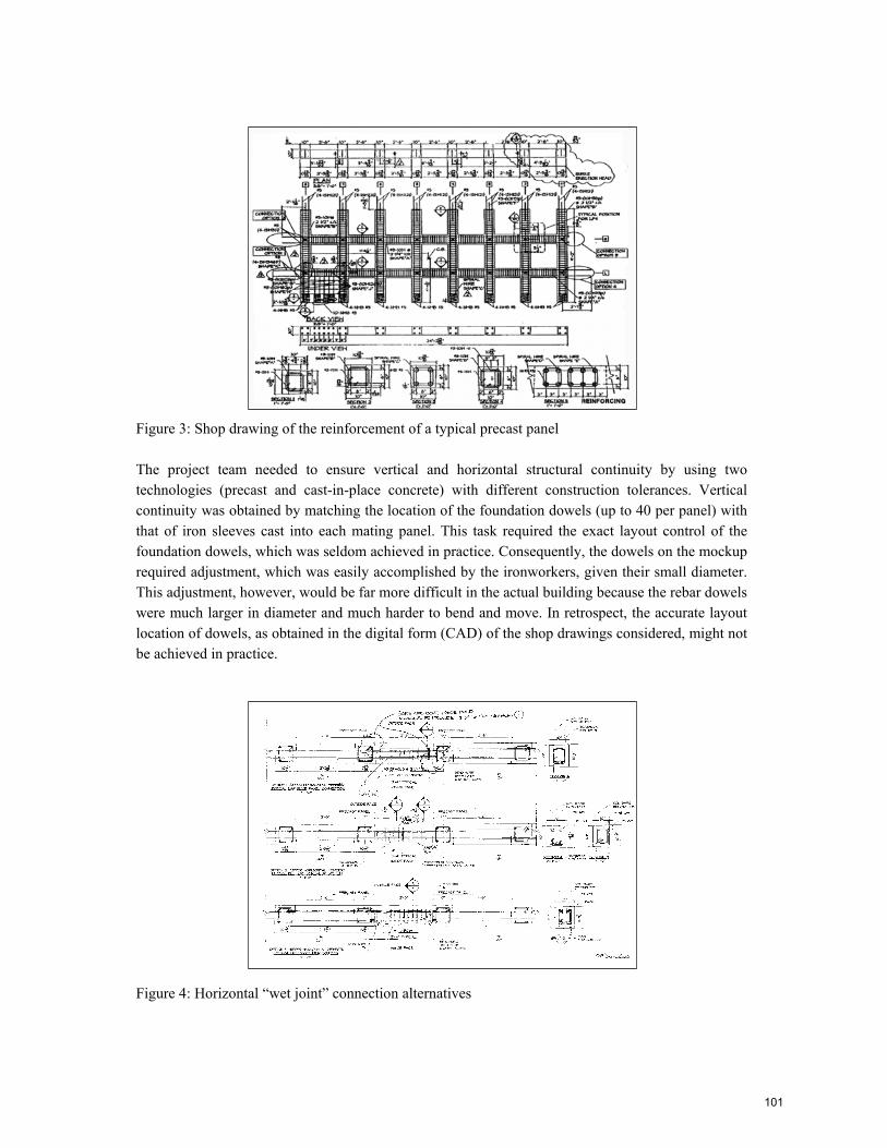
Figure 3: Shop drawing of the reinforcement of a typical precast panel
The project team needed to ensure vertical and horizontal structural continuity by using two technologies (precast and cast-in-place concrete) with different construction tolerances. Vertical continuity was obtained by matching the location of the foundation dowels (up to 40 per panel) with that of iron sleeves cast into each mating panel. This task required the exact layout control of the foundation dowels, which was seldom achieved in practice. Consequently, the dowels on the mockup required adjustment, which was easily accomplished by the ironworkers, given their small diameter. This adjustment, however, would be far more difficult in the actual building because the rebar dowels were much larger in diameter and much harder to bend and move. In retrospect, the accurate layout location of dowels, as obtained in the digital form (CAD) of the shop drawings considered, might not be achieved in practice.
Figure 4: Horizontal “wet joint” connection alternatives
101
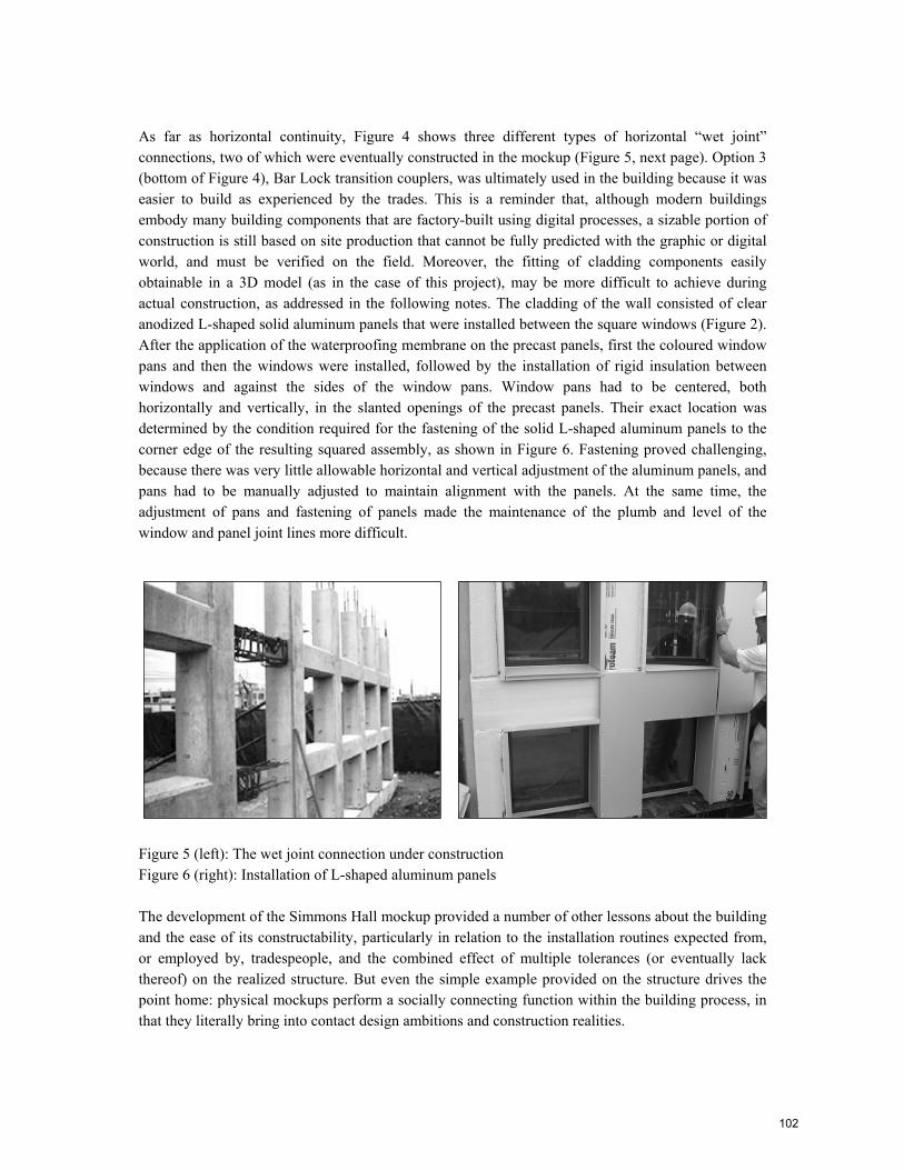
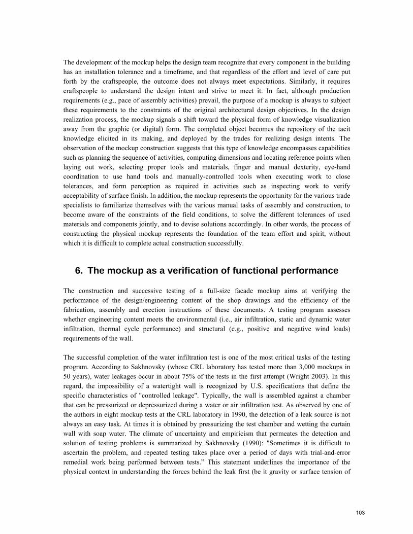
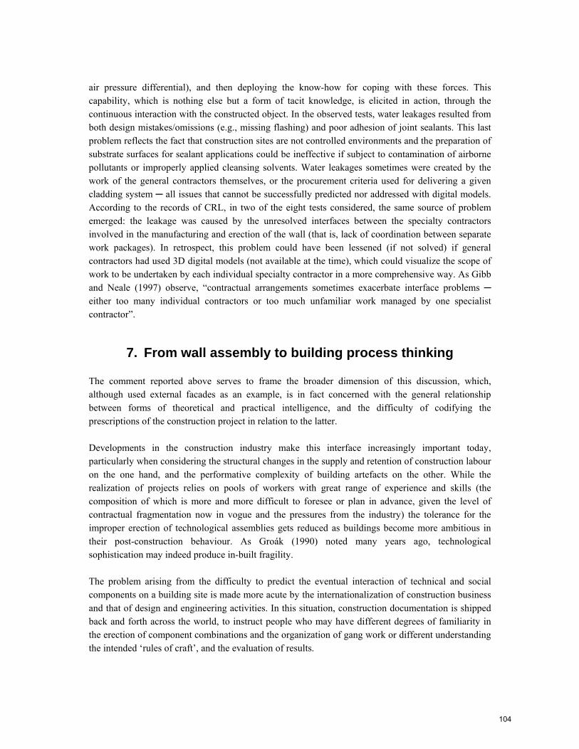
As far as horizontal continuity, Figure 4 shows three different types of horizontal “wet joint” connections, two of which were eventually constructed in the mockup (Figure 5, next page). Option 3 (bottom of Figure 4), Bar Lock transition couplers, was ultimately used in the building because it was easier to build as experienced by the trades. This is a reminder that, although modern buildings embody many building components that are factory-built using digital processes, a sizable portion of construction is still based on site production that cannot be fully predicted with the graphic or digital world, and must be verified on the field. Moreover, the fitting of cladding components easily obtainable in a 3D model (as in the case of this project), may be more difficult to achieve during actual construction, as addressed in the following notes. The cladding of the wall consisted of clear anodized L-shaped solid aluminum panels that were installed between the square windows (Figure 2). After the application of the waterproofing membrane on the precast panels, first the coloured window pans and then the windows were installed, followed by the installation of rigid insulation between windows and against the sides of the window pans. Window pans had to be centered, both horizontally and vertically, in the slanted openings of the precast panels. Their exact location was determined by the condition required for the fastening of the solid L-shaped aluminum panels to the corner edge of the resulting squared assembly, as shown in Figure 6. Fastening proved challenging, because there was very little allowable horizontal and vertical adjustment of the aluminum panels, and pans had to be manually adjusted to maintain alignment with the panels. At the same time, the adjustment of pans and fastening of panels made the maintenance of the plumb and level of the window and panel joint lines more difficult.
Figure 5 (left): The wet joint connection under construction Figure 6 (right): Installation of L-shaped aluminum panels
The development of the Simmons Hall mockup provided a number of other lessons about the building and the ease of its constructability, particularly in relation to the installation routines expected from, or employed by, tradespeople, and the combined effect of multiple tolerances (or eventually lack thereof) on the realized structure. But even the simple example provided on the structure drives the point home: physical mockups perform a socially connecting function within the building process, in that they literally bring into contact design ambitions and construction realities.
102
The development of the mockup helps the design team recognize that every component in the building has an installation tolerance and a timeframe, and that regardless of the effort and level of care put forth by the craftspeople, the outcome does not always meet expectations. Similarly, it requires craftspeople to understand the design intent and strive to meet it. In fact, although production requirements (e.g., pace of assembly activities) prevail, the purpose of a mockup is always to subject these requirements to the constraints of the original architectural design objectives. In the design realization process, the mockup signals a shift toward the physical form of knowledge visualization away from the graphic (or digital) form. The completed object becomes the repository of the tacit knowledge elicited in its making, and deployed by the trades for realizing design intents. The observation of the mockup construction suggests that this type of knowledge encompasses capabilities such as planning the sequence of activities, computing dimensions and locating reference points when laying out work, selecting proper tools and materials, finger and manual dexterity, eye-hand coordination to use hand tools and manually-controlled tools when executing work to close tolerances, and form perception as required in activities such as inspecting work to verify acceptability of surface finish. In addition, the mockup represents the opportunity for the various trade specialists to familiarize themselves with the various manual tasks of assembly and construction, to become aware of the constraints of the field conditions, to solve the different tolerances of used materials and components jointly, and to devise solutions accordingly. In other words, the process of constructing the physical mockup represents the foundation of the team effort and spirit, without which it is difficult to complete actual construction successfully.
6. The mockup as a verification of functional performance
The construction and successive testing of a full-size facade mockup aims at verifying the performance of the design/engineering content of the shop drawings and the efficiency of the fabrication, assembly and erection instructions of these documents. A testing program assesses whether engineering content meets the environmental (i.e., air infiltration, static and dynamic water infiltration, thermal cycle performance) and structural (e.g., positive and negative wind loads) requirements of the wall.
The successful completion of the water infiltration test is one of the most critical tasks of the testing program. According to Sakhnovsky (whose CRL laboratory has tested more than 3,000 mockups in 50 years), water leakages occur in about 75% of the tests in the first attempt (Wright 2003). In this regard, the impossibility of a watertight wall is recognized by U.S. specifications that define the specific characteristics of "controlled leakage". Typically, the wall is assembled against a chamber that can be pressurized or depressurized during a water or air infiltration test. As observed by one of the authors in eight mockup tests at the CRL laboratory in 1990, the detection of a leak source is not always an easy task. At times it is obtained by pressurizing the test chamber and wetting the curtain wall with soap water. The climate of uncertainty and empiricism that permeates the detection and solution of testing problems is summarized by Sakhnovsky (1990): "Sometimes it is difficult to ascertain the problem, and repeated testing takes place over a period of days with trial-and-error remedial work being performed between tests.” This statement underlines the importance of the physical context in understanding the forces behind the leak first (be it gravity or surface tension of
103
air pressure differential), and then deploying the know-how for coping with these forces. This capability, which is nothing else but a form of tacit knowledge, is elicited in action, through the continuous interaction with the constructed object. In the observed tests, water leakages resulted from both design mistakes/omissions (e.g., missing flashing) and poor adhesion of joint sealants. This last problem reflects the fact that construction sites are not controlled environments and the preparation of substrate surfaces for sealant applications could be ineffective if subject to contamination of airborne pollutants or improperly applied cleansing solvents. Water leakages sometimes were created by the work of the general contractors themselves, or the procurement criteria used for delivering a given cladding system ─ all issues that cannot be successfully predicted nor addressed with digital models. According to the records of CRL, in two of the eight tests considered, the same source of problem emerged: the leakage was caused by the unresolved interfaces between the specialty contractors involved in the manufacturing and erection of the wall (that is, lack of coordination between separate work packages). In retrospect, this problem could have been lessened (if not solved) if general contractors had used 3D digital models (not available at the time), which could visualize the scope of work to be undertaken by each individual specialty contractor in a more comprehensive way. As Gibb and Neale (1997) observe, “contractual arrangements sometimes exacerbate interface problems ─ either too many individual contractors or too much unfamiliar work managed by one specialist contractor”.
7. From wall assembly to building process thinking
The comment reported above serves to frame the broader dimension of this discussion, which, although used external facades as an example, is in fact concerned with the general relationship between forms of theoretical and practical intelligence, and the difficulty of codifying the prescriptions of the construction project in relation to the latter.
Developments in the construction industry make this interface increasingly important today, particularly when considering the structural changes in the supply and retention of construction labour on the one hand, and the performative complexity of building artefacts on the other. While the realization of projects relies on pools of workers with great range of experience and skills (the composition of which is more and more difficult to foresee or plan in advance, given the level of contractual fragmentation now in vogue and the pressures from the industry) the tolerance for the improper erection of technological assemblies gets reduced as buildings become more ambitious in their post-construction behaviour. As Groák (1990) noted many years ago, technological sophistication may indeed produce in-built fragility.
The problem arising from the difficulty to predict the eventual interaction of technical and social components on a building site is made more acute by the internationalization of construction business and that of design and engineering activities. In this situation, construction documentation is shipped back and forth across the world, to instruct people who may have different degrees of familiarity in the erection of component combinations and the organization of gang work or different understanding the intended ‘rules of craft’, and the evaluation of results.
104
Building Information Modeling (BIM) and CAD-CAM synergies are expected to dilute the risks of cultural dislocations or insufficient training by detecting the potential for physical clashes between building systems, and by simplifying manufacturing. Yet neither strategy seems to have, for the moment, what it takes to verify design decisions as they relate to site activity and localized craft: BIM visualizations offer 3D experiences of each part of the building object, but as constructed ─ after human intervention in a sense. CAD-CAM systems optimize a world of production that pre-dates the building site, at most indicating on-site handling patterns for the components and materials supplied.
8. Conclusions
To conclude, the transformation of design intents into physical reality has been presented in this paper as an information process in which the initial building description is progressively enriched through the interaction of project participants. Such an interaction is supported by knowledge visualization tools that assist in generating and communicating the evolving building representation. A critical phase of this transformation is represented by design realization, when the unitary architectural representation of the working drawings is transformed into a set of discrete descriptions for the fabrication, assembly and erection of main building parts (i.e., shop drawings), to be used during the construction phase. The design realization process builds upon the knowledge of the necessary means in the making of a building. This type of knowledge, as articulated in the discussion, has some tacit aspects that cannot be fully elicited with digital representation. Thus, the completion of design realization needs a different type of supporting tool, a physical mockup that compensates for the lack of contingent reality in digital modeling. Electronic technology, in fact, cannot capture or simulate the manual character of construction activities such as leveling, adjusting or finishing, the sensory experience of the spatial and physical object with its light, colour or texture, or even the coalition of skills assembled on site. Paradoxically, then, the more digital technology continues to support the design of new architectural forms, the more the physical reality and experience of mockups will be needed to verify the constructability and functionality of digital architecture, with its unproven translucency, colour and weightless plasticity. In this sense, digital and physical models should be considered as complementary tools in design realization. The former visualize the explicit contents of design and engineering knowledge while the latter physically realize such knowledge within the landscape of production determined by circumstances. The enhanced visualization capabilities of 3D models of course facilitate the construction of a physical model, but its ultimate testing is what, in the end, verifies their design and engineering intent.
References
Applebaum H A (1982) “Construction management: Traditional versus bureaucratic methods.” Anthropological Quarterly, 55 (4), 224-234.
Boehmig R L (1990) “Shop drawings: in need of respect.” Civil Engineering, March, 80-82.
105
DeLapp J, Ford D, Bryant J and Horlen J (2004) “Impacts of CAD on design realization.” Engineering, Construction and Architectural Management, 11(4), 284-291.
Eastman C, Teicholz P, Sacks R and Liston K (2008) BIM handbook: A guide for building information modeling for owners, managers, designers, engineers, and contractors. John Wiley & Sons, Hoboken, New Jersey.
Gibb A G F and Neale R H (1997) “Management of prefabrication for complex cladding: Case study.” Journal of Architectural Engineering, ASCE, 3 (2), 60-69.
Gonchar J and Reina P (2003) “Glass facades go beyond skin deep.” Engineering News-Record, February 10, 26-29.
Groák S (1990) “The decline of robust technologies in the building industry.” Building Research and Practice, 18(3), 162-168.
Groák S (1992) The idea of building. E&F Spon, London.
Hartman T and Fisher M (2007) “Supporting the constructability review with 3D/4D models.” Building Research and Information, 35 (1), 70-80.
King R (2001) Brunelleschi’s dome, Penguin Books, New York.
Kolarevic B (ed.) (2003) Architecture in the digital age: Design and manufacturing. Spon Press, New York.
Nonaka I (1991) “The knowledge-creating company.” Harvard Business Review, 69, 96-104.
Pietroforte R (1995) “Technological change of cladding systems: Implications for design and engineering arrangements.” Journal of Architectural Engineering, ASCE, 1 (3), 100-1007.
Pietroforte R (1997) “Shop drawing process of stone veneered cladding systems.” Journal of Architectural Engineering, ASCE, 3 (2), 70-79.
Polanyi M (1967) The tacit dimension. Routledge and Kegan Paul, London.
Sakhnosky A A (1990) Personal communication, 16 December 1990.
Schodek D, Bechthold M, Griggs K, Kao K M and Steinberg M (2005) Digital design and manufacturing. John Wiley & Sons, Hoboken, NJ.
Straus S G and McGrath J E (1994) “Does the medium matter? The interaction of task type and technology on group performance and member reactions.” Journal of Applied Psychology, 79 (1), 87-97.
106

Wright G (2003) “Four-sided compatibility: Curtain walls.” Building Design and Construction, June, 5-8.
107