Embed Size (px)
Citation preview

Physical Layer Signaling for the Next
Generation Mobile TV Standard
DVB-NGH
Author: José Mª Llorca Beltrán
Director: David Gómez Barquero
Tutor: Narcís Cardona Marcet
Start Date: 1/04/2010
Workplace: Mobile Communications Group of iTEAM

Physical Layer Signaling for the Next Generation Mobile TV Standard DVB-NGH 1
Objectives — This Master of Science degree thesis aims at investigating, studying and developing the new
physical layer for the new handled generation of terrestrial TV standard DVB-NGH. This new physical layer
is based on the DVB-T2 physical layer specification, but it introduces several advanced mechanisms to allow
the transmission of high definition TV services in mobile environments. The main objective of this thesis
work is focused on illustrating the benefits of the new physical layer when compared to T2 physical layer.
Methodology —A comparison study between the new standard and the previous DVB-T2 is carried out,
focusing on the adopted mechanisms and robustness enhancement techniques. Such study is performed by
simulating both DVB-T2 and DVB-NGH physical transmission chains in typical deployment scenarios.
Theoretical developments —The theoretical developments have been carried out following the
standardization process of DVB-NGH, where several proposals have been admitted and studied for
enhancing the NGH physical layer in different aspects, i.e. increasing the robustness, signaling capacity and
overhead reduction in comparison to the DVB-T2 physical layer.
Prototypes and lab tests — The DVB-T2 physical layer simulator has been developed according to the
standard and the DVB-NGH physical layer simulator has been programmed following the standardization
process, including all the approved proposals. Both simulators perform all the physical transmission chains
for DVB-T2 and DVB-NGH.
Results — The results shown in this work include performance curves, focusing on signaling robustness,
signaling capacity and overhead reduction. The DVB-NGH results have been compared to SAMSUNG‘s
(South Korea) in order to validate the robustness mechanisms in the standardization process of DVB-NGH.
The simulation results show a gain in robustness when adopting the DVB-NGH physical layer techniques
instead of DVB-T2. In addition, DVB-NGH improves signaling capacity and reduces the overhead.
Future work —The future work may be done by studying the effect of the signaling physical layer at
MIMO and SIMO environments. In addition, once the standardization process finalizes, another possible line
of investigation may be to study the most suitable configuration of L1 signaling for different mobile
transmission environments.
Publications — The contents and results of this thesis has been included in two technical reports on DVB-
NGH at the European R&D project ―ENGINES: Enabling Next GeneratIon NEtworks for broadcasting
Services‖:
Task Force TF1 ―System concept refinements for DVB-NGH‖- Technical Report TR 1.1
Intermediate Report on DVB-NGH Concept Studies. Section 3.1.2 L1 signaling robustness
improvement techniques, pp 36-48.
Task Force TF4 ―Hybrid access technologies‖ - Technical report TR4.1 Interim Report on
Hybrid Access Technologies. Section 4.5 L1 Signaling for the Hybrid Profile, pp 84-88.
2 Physical Layer Signaling for the Next Generation Mobile TV Standard DVB-NGH
Moreover, the enhancement studies of the physical layer signaling in DVB-T2 have been included in the
Implementation Guidelines of DVB-T2 in an updated version. This new version includes all the
developments since the Implementation Guidelines of DVB-T2 were published (i.e. T2-Lite). Our
contribution focused on the signaling path performance for different robustness types and modulations. The
study has been evaluated in different environments, SISO and SIMO, using the TU6 channel model with
Doppler frequency of 10 and 80 Hz.
ETSI TS 102 831 V1.3.1:―Digital Video Broadcasting (DVB); Implementation guidelines for a
second generation digital terrestrial television broadcasting system (DVB-T2)‖, section 14.7.
In addition, the contents and results of this thesis work, in conjunction with SAMSUNG contribution,
have been included in the signaling chapter of DVB-NGH standard:
"Handbook of Mobile Broadcasting", CRC Press. Second Edition.
Finally, a brief summary of DVB-NGH signaling has been included at ―Jornadas Telecom I+D 2011‖ paper:
―DVB-NGH, la Nueva Generación de Televisión Digital Móvil‖.
Abstract — The next generation mobile broadcasting standard DVB-NGH (Next Generation Handheld)
has enhanced the physical layer signaling of DVB-T2 (Second Generation Terrestrial) in several aspects:
higher signaling capacity, improved transmission robustness, reduced signaling overhead, and reduced peak-
to-average-power ratio (PAPR). The physical layer signaling of DVB-T2 and DVB-NGH is transmitted in
preamble OFDM symbols at the beginning of each frame. The preamble provides a means for fast signal
detection, enabling fast signal scanning, and it carries a limited amount of signaling data in a robust way that
allows accessing the physical layer pipes within the frame. This thesis provides an overview of the physical
layer signaling in DVB-NGH. Results are compared with DVB-T2.
Author: Llorca Beltrán, José María: [email protected]
Director: Gómez Barquero, David: [email protected]
Tutor: Cardona Marcet, Narcís: [email protected]
Valencia, 09-12-2011
Physical Layer Signaling for the Next Generation Mobile TV Standard DVB-NGH 3
Index
I. INTRODUCTION .............................................................................................................................. 5
I. 1 DIGITAL VIDEO BROADCASTING – NEW GENERATION HANDLED (DVB-NGH) .......................... 5
I. 2 MOTIVATION ................................................................................................................................ 5
II. AN OVERVIEW OF THE PHYSICAL LAYER SIGNALING IN DVB-T2 ........................... 6
III. IMPROVED PHYSICAL LAYER SIGNALING FOR DVB-NGH .......................................... 9
III.1. INCREASED SIGNALING CAPACITY IN DVB-NGH ......................................................................... 10
III.2. IMPROVED L1 SIGNALING ROBUSTNESS IN DVB-NGH ................................................................. 11
III.3. INCREASED L1 SIGNALING OVERHEAD REDUCTION IN DVB-NGH............................................... 17
III.4. REDUCED PAPR FOR L1 SIGNALING IN DVB-NGH ...................................................................... 21
IV. RESULTS AND DISCUSSIONS ................................................................................................ 22
IV.1. CAPACITY IMPROVEMENTS RESULTS ............................................................................................ 22
IV.2. ROBUSTNESS IMPROVEMENTS RESULTS ........................................................................................ 24
IV.3. OVERHEAD IMPROVEMENTS RESULTS ........................................................................................... 33
V. OPTIMIZATION OF THE PHYSICAL LAYER SIGNALING CONFIGURATION FOR THE
DATA PATH CONFIGURATION .................................................................................................... 36
VI. CONCLUSIONS .......................................................................................................................... 38
ACKNOWLEDGMENTS ....................................................................................................................... 39
REFERENCES ........................................................................................................................................ 39

4 Physical Layer Signaling for the Next Generation Mobile TV Standard DVB-NGH

Physical Layer Signaling for the Next Generation Mobile TV Standard DVB-NGH 5
I. INTRODUCTION
I. 1 Digital Video Broadcasting – New Generation Handled (DVB-NGH)
The DVB-NGH (Next Generation Handheld) standard is the mobile evolution of the European
standard Digital Terrestrial Television (DTT) for the second generation DVB-T2 (Terrestrial 2nd
generation). The DVB-T2 was submitted to ETSI in 2008, and will be taken into operative use
during 2010. This second generation system provides about 50% increase of physical layer capacity
compared to the previous standards. DVB-T2 is in its first stage targeting for fixed reception.
Providing the same or better capacity increase for portable, mobile and handheld broadcasts (DVB-
NGH), require new technical concepts.
For this reason, DVB-NGH has been thought to be the mobile broadcasting standard reference
worldwide, with better performance in terms of capacity and coverage to the existing mobile
technologies, such as, the first mobile DTV generation standard DVB-H (Handled), the hybrid
terrestrial-satellite mobile DTV standard DVB-SH (Satellite to Handhelds), or cell broadcast
standard MBMS (Multimedia Broadcast Multimedia Services).
One of the main advantages of DVB-NGH will be the possibility to transmit DVB-T2 and
DVB-NGH in the same multiplex (channel RF), reusing the existing network infrastructure without
the need to deploy on new dedicated networks. This can significantly reduce the investment needed
to start providing mobile services. NGH services would be transmitted in frames FEFs (Future
Extension Frames) within a DVB-T2 multiplex, illustrated on figure 1.
Thus, it would be possible to transmit high definition services or 3D TV for fixed terminals in
T2 frames and mobile services in a very robust transmission way in the NGH frames over FEF
frames [6].
Fig. 1. T2 Multiplex with NGH frames over FEFs frames.
I. 2 Motivation
DVB-NGH is based on DVB-T2 physical layer specification, but introduces several advanced
mechanisms and techniques that allow the transmission of high definition TV services. This thesis
aims to investigate study and develop the new physical layer for the new handled generation of
terrestrial TV standard. The main objective of this thesis is focus on how these mechanisms
enhance the new physical layer in compare to T2 physical layer.

6 Physical Layer Signaling for the Next Generation Mobile TV Standard DVB-NGH
This thesis provides an overview of the physical layer signaling in the new generation mobile
broadcasting DVB-NGH standard. The rest of the thesis is structured as follows. Section II briefly
reviews the physical layer signaling in DVB-T2. Section III describes the signaling capacity
improvements, focuses on the robustness enhancements, the signaling overhead, and finally the
PAPR improvement of the L1 transmission in DVB-NGH. Section IV deals with the performance
of the L1 signaling and the data path in DVB-NGH. Finally, the thesis is concluded with Section V.
II. AN OVERVIEW OF THE PHYSICAL LAYER SIGNALING IN DVB-T2
The physical layer signaling in the second generation digital terrestrial TV standard DVB-T2
(Second Generation Terrestrial) has two main functions. First of all, it provides a means for fast
signal detection, enabling fast signal scanning. Secondly, it provides the required information for
accessing the Layer-2 (L2) signaling and the services themselves. The purpose of the L2 signaling
is to associate the services with the physical layer pipes (PLPs) and with the network information.
As the physical layer signaling enables the reception of the actual data, it should naturally be more
robust against channel impairments than the data itself. Furthermore, in order to maximize the
system capacity, it should introduce as little overhead as possible.
The physical layer signaling of DVB-T2 is transmitted in preamble OFDM symbols at the
beginning of each frame, known as P1 and P2 symbol(s), see figure 2. The preamble carries a
limited amount of signaling data in a robust way. The frames begin with a preamble consisting of
one P1 symbol and one or several P2 symbols. The number of P2 symbols in the frame depends on
the FFT size of the transmission mode (e.g., two symbols for 8K FFT). The preamble is followed
by a configurable number of data symbols. The maximum length of a T2 frame is 250 ms.
Fig. 2. Physical layer signaling in DVB-T2 transmitted in preamble P1 and P2 OFDM symbols.
The physical layer signaling is structured in three different parts which are sequentially
received: the P1 signaling carried in the P1 symbol, and the L1 pre and L1 post Layer-1 (L1)
signaling carried in the P2 symbol(s). The P1 symbol is used in the initial scan for detecting the
presence of DVB-T2 signals on the current frequency. It carries some basic transmission

Physical Layer Signaling for the Next Generation Mobile TV Standard DVB-NGH 7
parameters, such as the frame type (e.g., T2, T2-Lite, or NGH), and it enables the reception of the
P2 symbol(s). The L1 signaling transmitted in the P2 symbol(s) is divided into two parts: L1 pre
and L1 post-signaling. The L1 pre-signaling provides information on the current super frame,
relating to the network topology, configuration and to the transmission protocols used within the
super frame (e.g., TS or GSE). The L1 pre enables the reception and decoding of the L1 post-
signaling, which contains the information needed for extracting and decoding the data PLPs from
the frames.
The physical layer signaling of DVB-T2 was designed such that it can always be made more
robust than the data path. The most robust transmission mode for the data is QPSK modulation
with code rate 1/2. The P1 symbol consists of a 1k OFDM symbol, which is DBPSK (Differential
Binary Phase Shift Keying) modulated in the frequency direction with a higher power than the data
OFDM symbols. The P1 carriers are boosted to normalize the power between the P1 and the data
OFDM symbols.
The L1 pre information is BPSK (Binary Phase Shift Keying) modulated and protected with a
code rate 1/5. The amount of L1 pre-signaling data is fixed and equal to 200 bits, and the size of the
LDPC codeword is 16200 bits (16K). Thus, the LPDC codeword needs to be shortened (i.e., the
codeword shall be padded with zeros following a shortening pattern in order to fulfill the LDPC
information codeword) and punctured (i.e., not all the generated parity bits are transmitted) to be
able to transmit this small amount of data. These two mechanisms decrease the outperformance of
the system.
The L1 post information is encoded with a 16K LDPC with a code rate 4/9. The amount of the
L1 post information in DVB-T2 depends on the transmission system parameters (mainly the
number of PLPs used in the system).
Fig. 3. Modulation and error coding for L1 signaling.
8 Physical Layer Signaling for the Next Generation Mobile TV Standard DVB-NGH
The T2 specification defines an optimized puncturing and shortening scheme with a variable
code rate depending on the size of the L1-post information. The effective code rate decreases as the
signaling information decreases (the minimum value is 1/4 and the maximum 4/9). This rate-
control compensates the performance degradation of LDPC decoding due to padding and
puncturing, and it ensures the preservation of the coverage area. The modulation order of the L1-
post is the only parameter of the signaling preamble that can be chosen by the broadcast network
operator. The possible schemes are: BPSK, QPSK, 16-QAM, and 64-QAM. It is recommended to
use one modulation order lower than the data (e.g., 64 QAM in case of 256QAM for data). This
way, it is possible to assure that the signaling is more robust than the data, and the signaling
overhead is minimized [1][2].
The transmission and detection of the preamble P1 symbol is very robust, and it can be correctly
received even at negative signal-to-noise ratios (SNR) under mobility conditions [4]. The
transmission of the rest of the physical layer signaling in the P2 symbol(s) can be configured
sufficiently robust in rather static reception conditions. However, in mobile reception conditions
the robustness of the L1 signaling may not be high enough due to the lack of time diversity. DVB-
T2 implements a flexible time interleaver at the physical layer in order to improve the robustness of
the signal against impulse noise and exploit the time diversity in mobile channels [4][5]. Since the
L1 signaling is only spread in one or few OFDM symbols, it can be less robust than the data in
mobile channels despite of having a lower modulation order. The L1 signaling can be optionally
transmitted in-band together with the data, such that it has the same robustness. However, the full
signaling from the preamble needs to be received at least when beginning the reception or changing
between services.
One possibility to increase the robustness of the L1 post-signaling is to further reduce the
modulation order, such that it can be received in all circumstances. This increases the signaling
overhead, and reduces the number of PLPs that can be used in the system. Moreover, this approach
is not valid for the most robust data transmission mode (QPSK 1/2), since the L1 pre cannot reduce
the modulation more than BPSK. Another possibility to increase the robustness of the L1 signaling
transmission and improve the time diversity consists of transmitting information in the preamble of
each frame about the current frame and the next frame. This is called repetition of L1 post-
signaling, and it increases the probability of correctly receiving the L1 signaling information after
receiving two frames at the expense of increased signaling overhead[2].
Physical Layer Signaling for the Next Generation Mobile TV Standard DVB-NGH 9
III. IMPROVED PHYSICAL LAYER SIGNALING FOR DVB-NGH
The next generation mobile broadcasting standard DVB-NGH (Next Generation Handheld) has
enhanced the physical layer signaling of DVB-T2 in four different aspects:
Improved transmission robustness.
Reduced signaling overhead.
Higher signaling capacity.
Reduced peak-to-average power ratio (PAPR).
DVB-NGH adopts for L1 signaling new mini 4K LDPC codes of size 4320 bits (4K). Although
4K LDPC codes have a worse performance than 16K LDPC codes, the reduced size of the 4K
LDPC codes is more suitable for the L1 signaling because reduces the amount of shortening and
puncturing. The adopted 4K LDPC codes have the same parity check matrix structure than the 16K
LDPC codes used for data protection. This allows for efficient implementations at the transmitter
and receiver side efficiently sharing the same logic. On the other hand, two mechanisms have been
adopted in DVB-NGH, known as Incremental Redundancy (IR) and Additional Parity (AP). With
the AP mechanism, the second frame contains the punctured bits not transmitted in the first frame.
In case there is need for more parity bits, the IR mechanism extends the original 4K LDPC code
into an 8K LDPC code.
The robustness improvement of the L1 signaling in DVB-NGH can be translated into a
reduction of the signaling overhead. But DVB-NGH has restructured the L1 signaling structure of
DVB-T2 in order to further reduce the signaling overhead. Instead of signaling the configuration of
each PLP (MODCODTI, modulation, code rate, and time interleaving configuration), PLPs are
associated in groups with the same settings, reducing the required L1 signaling information.
Furthermore, it is possible to split in several frames signaling parameters which are in practice
static, and which are transmitted in DVB-T2 in every frame.
DVB-NGH has also increased the signaling capacity of both P1 and P2 preamble symbols. In
DVB-T2, the preamble P1 symbol provides seven signaling bits. For the satellite profile of DVB-
NGH an additional preamble P1 (aP1) symbol has been introduced in order to increase the
signaling capacity of the P1 symbol. The P1 symbol signals the presence of the aP1 symbol. The
aP1 symbol is only transmitted for hybrid terrestrial-satellite DVB-NGH networks, such that it is
not transmitted if it is not needed. The aP1 symbol improves the detection performance of DVB-
NGH compared to DVB-T2 due to the presence of a second preamble P1 symbol. On the other
hand, in order to avoid limitations in the maximum number of PLPs that can be used in the system
due to signaling constraints, DVB-NGH has defined a new signaling L1 PLP for the L1-post

10 Physical Layer Signaling for the Next Generation Mobile TV Standard DVB-
NGH
information. The signaling L1 PLP is transmitted at the beginning of the frame and can be
transmitted outside the P2 symbols.
Finally, the last improvement of the physical layer signaling in DVB-NGH compared to DVB-
T2 is related to a reduction of the PAPR of the L1 signaling. In DVB-T2, the PAPR problem was
observed after the first receivers were manufactured. This problem is due to the lack of energy
dispersal scrambling for the L1 signaling data, normally with large number of PLPs result in peaks
in the time domain signal during the P2 symbols. Several improvements have been done to
overcome this situation, based on a combination of the PAPR reduction mechanism of DVB-T2
ACE (Active constellation Extension) and TR (Tone Reservation), and using reserved bits for
future use and additional bias balancing cells. DVB-NGH simply adopts a scrambling for the L1
signaling information based on the mechanism employed to scramble the data.
III.1. Increased Signaling Capacity in DVB-NGH
Introduction
This section describes two methods used to improve the capacity of L1 signaling in DVB-NGH
compared to DVB-T2. These two methods increase the P1 capacity with an additional P1symbol,
and the L1 signaling with the transmission of the signaling PLP.
In DVB-T2, the P1 symbol provides seven signaling bits that define some essential transmission
parameters. In contrast, these seven bits are not sufficient and additional bits are required in DVB-
NGH. The future NGH system includes a satellite component and additional P1 symbol is used to
distinguish between the terrestrial profile and the hybrid profile (Terrestrial and Satellite
component) and MIMO configurations.
In addition, the L1 capacity has been improved by transmitting the L1 post-signaling in a PLP
data, called signaling PLP, which can extend outside the P2 symbols. The signaling PLP concept
may be applied to a stand-alone NGH system and to a combined NGH/T2 system (FEF
integration).
Additional Preamble aP1 OFDM Symbol for the Satellite Component
In DVB-NGH, an Additional Preamble P1 (aP1) is needed to identify the Satellite Component. The
aP1 has the same structure and the same advantages than the P1 symbol. These advantages are the
robustness signal discovery against false detection and the resilience to CW interference.
The additional Preamble is designed for avoiding the interference with the P1 symbol by
scrambling with a different PRBS sequence and using a different K-offset value from the P1
symbol.

Physical Layer Signaling for the Next Generation Mobile TV Standard DVB-NGH 11
This new preamble provides 7 signaling bits in a new field, S3 field. With this new field the
new developments added in NGH are signaled, as MIMO configurations, satellite signal type and
satellite diversity. This additional Preamble is used only for the Satellite Profile. With this
information the receiver is able to receive the P2 symbols for the Terrestrial Profile or Hybrid
Profile. [17]
Layer 1 Signaling PLP
The L1 signaling PLP is one possible method to improve the capacity of L1 signaling compared to
DVB-T2. The L1 signaling PLP increases the capacity of L1 signaling by transmitting the L1 post-
signaling in a signaling PLP, which can extend outside the P2 symbols.
The general structure of the signaling is according to T2, i.e., the preamble consists of one P1
symbol and a fixed number of P2 symbols that carry L1 pre and L1 post-signaling data. The fixed
length L1 pre-signaling could be transmitted as in T2, i.e. using zig-zag mapping over the P2
symbols, with fixed modulation and coding scheme. In addition, the L1 post-signaling could be
transmitted in a signaling PLP at the beginning of the frame, and it should be composed of
configurable and dynamic parts with individual CRCs. Modulation for the NGH L1 post-signaling
should be a configurable parameter and signaled in NGH L1 pre-signaling [18][8] .
Fig. 4. Increasing signaling capacity by signaling PLP concept.
III.2. Improved L1 Signaling Robustness in DVB-NGH
Introduction
DVB-NGH adopts the same L1 signaling structure from DVB-T2, but introduces several
differences that enhance the L1 robustness and reduces the L1 overhead. For this reason, DVB-
NGH adopts for L1 signaling new 4K LDPC codes of size 4320 bits. The shrunk size of 4K LDPC
codes is more suitable for signaling, and considerably reduces the amount of shortening and
12 Physical Layer Signaling for the Next Generation Mobile TV Standard DVB-
NGH
puncturing that degrades the outperformance of L1 signaling. The properties of these new codes are
explained at 4K LPDC section.
L1 pre-signaling is always BPSK (Binary Phase Shift Keying) modulated and protected with the
most robust LDPC code rate 1/5. The amount of L1 pre-signaling data is 200 bits and the amount
of BCH redundancy is 60 bits (5 bits correction).
The L1 post information is protected with a variable code rate length 4K LDPC code
concatenated with the BCH code (60 bits). The effective code rate decreases as the signaling
information decreases (the minimum value is 1/4 and the maximum 1/2). This rate-control, as in
DVB-T2, compensates the performance degradation of LDPC decoding due to padding and
puncturing. The modulation schemes used with the L1-post signaling is a BPSK. The amount of the
L1-post information depends on the transmission system parameters, e.g. the amount of PLPs used
in the system.
Thus, the resulting two LDPC code words needs to be shortened and punctured to be able to
transmit this small amount of data using the given LDPC with the code rate used, respectively.
The shortening and puncturing methods degrades the L1 performance and are explained at
Additional Parity section.
As in DVB-T2, the coded signaling blocks are inserted to the carriers of the P2 symbols so that
L1 pre and L1 post data are evenly distributed over all P2 symbols of one NGH frame. The PLP
data is inserted to the carriers available in P2 symbols after the insertion of the L1 pre and L1 post-
signaling. The encoding process for L1 signaling is the same as it is illustrated at figure 3.
DVB-NGH improves L1 signaling robustness from DVB-T2 by adopting several mechanisms.
These mechanisms are divided in two groups: 1) mechanisms that enhance the L1 signaling
robustness by getting more time diversity in the signal, as Additional Parity and Incremental
Redundancy methods, and 2) The insertion of new LDPC codes, new 4K LDPC codes, that gets
better performance than 16K LDPC codes for signaling.
16K LDPC codes are used in DVB-T2 for L1 signaling with shortening and puncturing methods
in order to adapt the information to the code word. These methods degrade the outperformance of
L1 signaling and its robustness is considerable reduced. DVB-NGH 4k codes were introduced to
optimize the performance provided by the 16K codes used in DVB-T2, providing several
advantages. The abovementioned mechanisms that enhance the time diversity of signaling are
Incremental Redundancy (IR) and Additional Parity (AP).
The technique of AP consists of transmitting punctured LDPC parity bits on the previous NGH
frame and exploiting the time diversity of the mobile channel, resulting in an increase of the L1
signaling robustness but reducing the effective code rate. This new technique obtains a better
performance in comparison with just repeating the information in the frame (L1-repetition).
The main idea behind IR is to extend this new 4k LDPC codes with additional parity bits
(another 4k code word) to provide additional robustness when are required. IR uses special 8K

Physical Layer Signaling for the Next Generation Mobile TV Standard DVB-NGH 13
LDPC codes (8640 bits) for coding L1 signaling information bits. These codes have been created to
obtain the same parity bits as 4k LDPC codes, taken into account the first 4K parity bits.
Finally, and since the L1 pre and the configurable part of the L1 post are constant during each
super-frame, the receiver may also apply soft combining in these fields to increase the L1 pre/post
robustness.
4K LDPC Codes
The L1 signaling information of DVB-T2 does not generally fill one 16K LDPC code word. In
order to keep the code rate effectiveness, the LDPC code word needs to be shortened and
punctured, which degrades the performance. DVB-NGH adopts for L1 signaling new 4K LDPC
codes of size 4320 bits [12].
The shrunk size of 4K LDPC codes is more suitable for signaling, and considerably reduces the
amount of shortening and puncturing, see table 1. The code rates adopted for L1 pre and L1 post in
DVB-NGH are 1/5 and variable code rate, from 1/4 to 1/2 depending the information length,
respectively. Note that effective code rate of the 16K/4K LDPC code with 1/4 is 1/5, where the
effective code rate is defined as the information length over the encoder output length. Details of
how to shorten and puncture the LDPC code are described in Additional Parity mechanism.
L1
Signaling
LDPC
Codes
Code
Rate
Information
bits
Parity bits NGH L1
Signaling
Shortening
bits
Puncturing
bits
L1 Pre 4K 1/5 1080 3240 280 800 2120
16K 1/5 4000 12000 200 3200 11200
L1 Post 4K 1/2 2160 2160 640 1520 1520
16K 4/9 7200 9000 640 6560 8200
Table 1. 4K Codes vs 16K Codes
The 4K LDPC code have been created with identical structure of parity check matrix in order to
share the encoder and decoder efficiently. The information part is created by dividing the
information part in 72 bits-groups with Qldpc= 30 bits cyclic shift and the parity part has staircase
format. The number of the grouping factor (72 bits-groups) has been chosen because it is a divisor
of the number used for 16K DVB-T2 LDPC codes. Consequently, the 4K codes are 72-periodics.
The 4K LDPC codes enables lower coding rate and they achieve very close to 16K effective
overall code rates (after shortening and puncturing).
The benefits of this new 4K LDPC codes are less number of iterations, lower complexity and
higher efficiency at the handled decoder. The 4K needs lower number of iterations in compare of
16K to get a target FER of 10-2
(26 iterations less) [14]. This significant improvement is achieved
thanks to much less shortening and puncturing methods with the 4K codes. This smaller number of
less complex iterations converts into much less power consumption and fast convergence.
14 Physical Layer Signaling for the Next Generation Mobile TV Standard DVB-
NGH
However, in term of performance, the shorter 4K FEC is some tenths of dB lower than 16K
FEC codes. 16K LDPC codes provide a better performance for the same information length than
4K LDPC codes without padding and puncturing. The 4K codes do not bring an improvement in
performance.
Additional Parity (AP)
The technique of AP consists of transmitting punctured LDPC parity bits on the previous NGH
frame and exploiting the time diversity of the mobile channel, resulting in an increase of the L1
signaling robustness but reducing the effective code rate. This new technique obtains a better
performance in comparison with just repeating the information in the frame (L1 repetition) [15].
L1 post-signaling is coded by an inner BCH and 4K LDPC outer code. Shortening and
puncturing methods allow maintaining the global code rate according to the information length.
The key issue of AP is the puncturing method and how to use profits of this method.
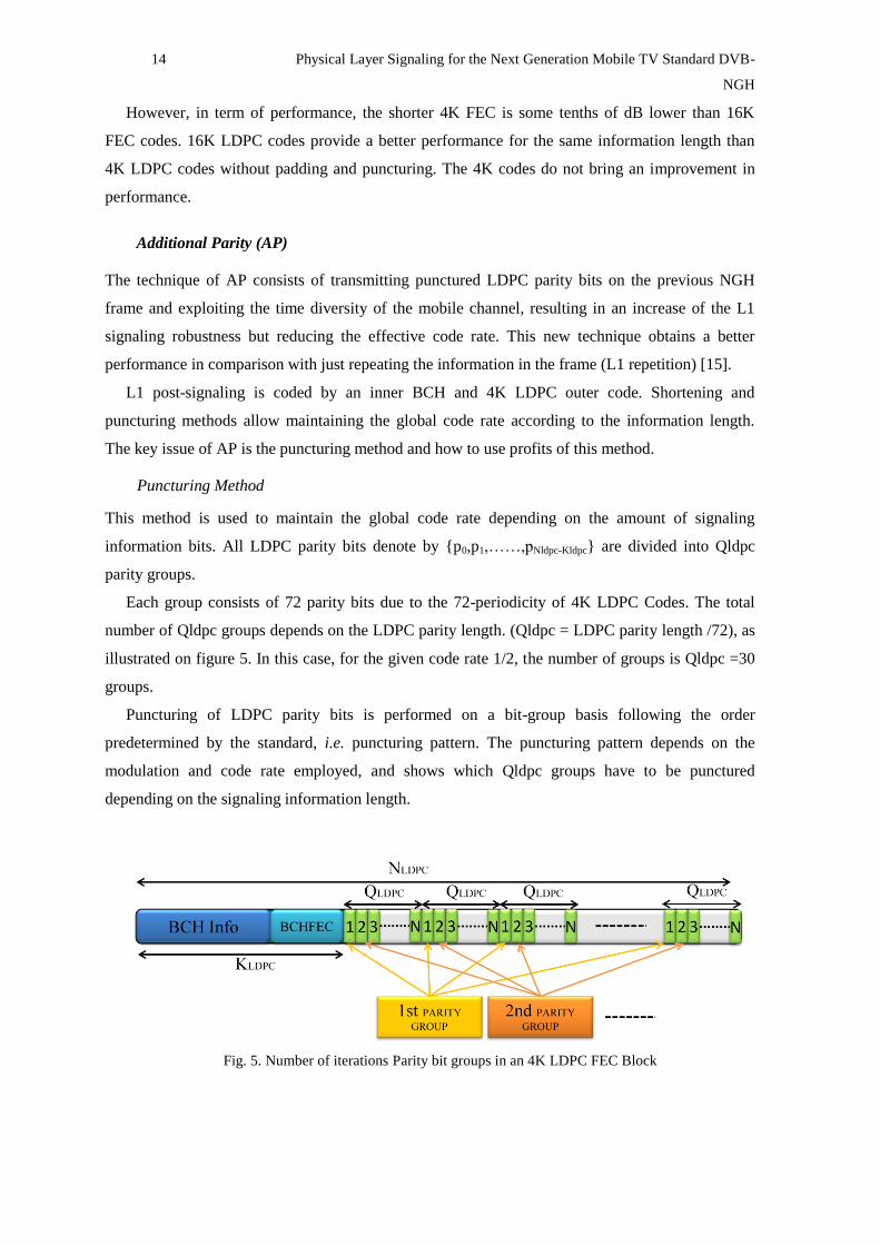
Puncturing Method
This method is used to maintain the global code rate depending on the amount of signaling
information bits. All LDPC parity bits denote by {p0,p1,……,pNldpc-Kldpc} are divided into Qldpc
parity groups.
Each group consists of 72 parity bits due to the 72-periodicity of 4K LDPC Codes. The total
number of Qldpc groups depends on the LDPC parity length. (Qldpc = LDPC parity length /72), as
illustrated on figure 5. In this case, for the given code rate 1/2, the number of groups is Qldpc =30
groups.
Puncturing of LDPC parity bits is performed on a bit-group basis following the order
predetermined by the standard, i.e. puncturing pattern. The puncturing pattern depends on the
modulation and code rate employed, and shows which Qldpc groups have to be punctured
depending on the signaling information length.
Fig. 5. Number of iterations Parity bit groups in an 4K LDPC FEC Block

Physical Layer Signaling for the Next Generation Mobile TV Standard DVB-NGH 15
AP Generation rule
AP extends the new 4k LDPC with additional parity bits to provide additional robustness. These
additional bits are some punctured bits that belong to the following frame. When AP is applied, the
new configuration of the code word results as shown in figure 6. The length of this additional part
is denoted as AP length, and it is obtained as function of three parameters K, AP_RATIO and the
length of the original parity bits corresponding to the L1_Post_block, where K is defined as 0.35
and the AP_RATIO can be {0,1,2,3,..}.
Fig. 6. The resulting LDPC code word with Additional Parity bits
When the AP mechanism is used, for a given frame the punctured bits are transmitted first.
Consequently, the parity is sent in two consecutives frames getting more time diversity. The
additional parity is sent in the previous frame and the basic FEC is sent with information at the
same time, as depicted in figure 7 where Info, B, LDPC FEC and AP, are the information fields,
BCH FEC bits, basic parity bits and additional parity bits, respectively.
Fig. 7. Additional Parity transmission method
Advantages
The main advantage of using AP is that the effective coding rate for L1 signaling can be reduced
without any LDPC matrix. The L1 signaling robustness has improved as a result of the increment
of the time diversity of the mobile channel. The following table shows the effective code rate
achieved for different configurations with parameter K=0,35.
Num
PLP K_sig
Parity
bits
AP (bits) Code Rate Achieved
AP
Ratio
{1}
AP
Ratio
{2}
AP
Ratio
{3}
AP
Ratio
{0}
AP
Ratio
{1}
AP
Ratio
{2}
AP
Ratio
{3}
1 642 1111 388 776 1164 0.3662 0.2999 0.2539 0.2201
Table 2. Additional Parity benefits
16 Physical Layer Signaling for the Next Generation Mobile TV Standard DVB-
NGH
Incremental Redundancy (IR)
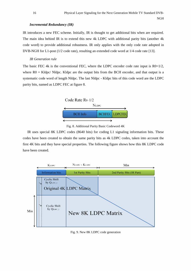
IR introduces a new FEC scheme. Initially, IR is thought to get additional bits when are required.
The main idea behind IR is to extend this new 4k LDPC with additional parity bits (another 4k
code word) to provide additional robustness. IR only applies with the only code rate adopted in
DVB-NGH for L1-post (1/2 code rate), resulting an extended code word at 1/4 code rate [13].
IR Generation rule
The basic FEC 4k is the conventional FEC, where the LDPC encoder code rate input is R0=1/2,
where R0 = Kldpc/ Nldpc. Kldpc are the output bits from the BCH encoder, and that output is a
systematic code word of length Nldpc. The last Nldpc - Kldpc bits of this code word are the LDPC
parity bits, named as LDPC FEC at figure 8.
Fig. 8. Additional Parity Basic Codeword 4K
IR uses special 8K LDPC codes (8640 bits) for coding L1 signaling information bits. These
codes have been created to obtain the same parity bits as 4k LDPC codes, taken into account the
first 4K bits and they have special properties. The following figure shows how this 8K LDPC code
have been created.
Fig. 9. New 8K LDPC code generation
Physical Layer Signaling for the Next Generation Mobile TV Standard DVB-NGH 17
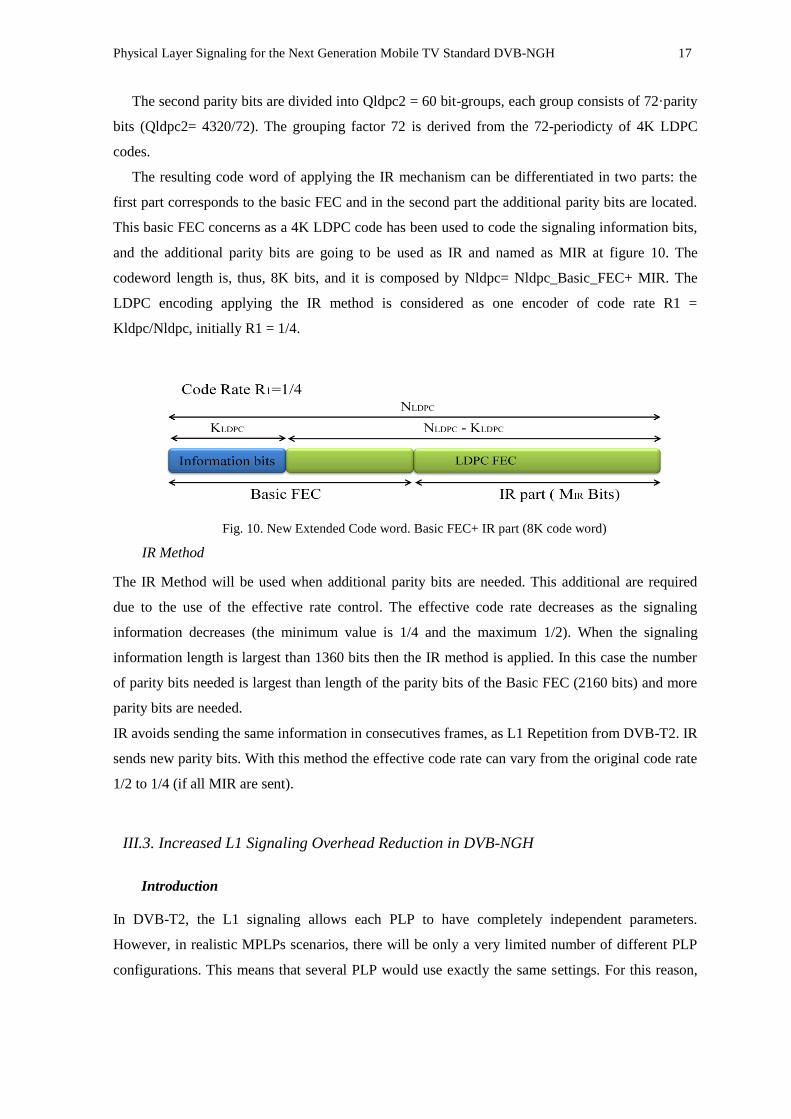
The second parity bits are divided into Qldpc2 = 60 bit-groups, each group consists of 72·parity
bits (Qldpc2= 4320/72). The grouping factor 72 is derived from the 72-periodicty of 4K LDPC
codes.
The resulting code word of applying the IR mechanism can be differentiated in two parts: the
first part corresponds to the basic FEC and in the second part the additional parity bits are located.
This basic FEC concerns as a 4K LDPC code has been used to code the signaling information bits,
and the additional parity bits are going to be used as IR and named as MIR at figure 10. The
codeword length is, thus, 8K bits, and it is composed by Nldpc= Nldpc_Basic_FEC+ MIR. The
LDPC encoding applying the IR method is considered as one encoder of code rate R1 =
Kldpc/Nldpc, initially R1 = 1/4.
Fig. 10. New Extended Code word. Basic FEC+ IR part (8K code word)
IR Method
The IR Method will be used when additional parity bits are needed. This additional are required
due to the use of the effective rate control. The effective code rate decreases as the signaling
information decreases (the minimum value is 1/4 and the maximum 1/2). When the signaling
information length is largest than 1360 bits then the IR method is applied. In this case the number
of parity bits needed is largest than length of the parity bits of the Basic FEC (2160 bits) and more
parity bits are needed.
IR avoids sending the same information in consecutives frames, as L1 Repetition from DVB-T2. IR
sends new parity bits. With this method the effective code rate can vary from the original code rate
1/2 to 1/4 (if all MIR are sent).
III.3. Increased L1 Signaling Overhead Reduction in DVB-NGH
Introduction
In DVB-T2, the L1 signaling allows each PLP to have completely independent parameters.
However, in realistic MPLPs scenarios, there will be only a very limited number of different PLP
configurations. This means that several PLP would use exactly the same settings. For this reason,
18 Physical Layer Signaling for the Next Generation Mobile TV Standard DVB-
NGH
DVB-NGH has changed the L1 signaling paradigm for multiple PLPs, associating PLPs with the
same features and reducing the signaling overhead of the L1 configurable field.
Moreover, all L1 signaling fields: L1 pre, L1 configurable, and L1 dynamic are transmitted in
every frame. The L1 pre signals the properties of the channel (e.g., guard interval, pilot pattern,
etc.), and enables the reception of the L1 configurable. The L1 configurable signals the
configuration of the PLPs (e.g., MODCOD, time interleaving settings, frequencies...). The L1
dynamic field signals where the data is placed over the T2 frame. The values of the L1 dynamic
can change frame by frame, but the L1 pre and L1 configurable may only change on a super frame
basis. But in practice, they only change when the multiplex of the RF channel is reconfigured,
which occurs rather seldom. For these reasons, DVB-NGH allows the transmission of the L1 Pre
and L1 configurable signaling fields to be split into several frames.
L1 Configurable Overhead Reduction
In DVB-T2, there is a PLP signaling loop in the L1 configurable field that defines all the features
of each PLP. The signaling information includes, among other things, the PLP identification
number, the modulation, code rate, and time interleaving configuration, and the PLP location inside
the frame and its length. In DVB-NGH, the PLP signaling loop in L1 configurable has been re-
structured in order to reduce the signaling overhead, associating PLPs with the same settings. The
PLP signaling loop is split into two different loops. The first loop defines the different PLP
configuration modes. Each PLP configuration mode is associated with a short code of six bits. The
second loop is a loop overall PLPs, and associates each PLP with a PLP mode. In this way, only six
signaling bits per PLP are required in the PLP loop, and only a very limited number of PLP
configurations are required inside the PLP configuration loop. The adopted solution allows for a
totally general case, with up to 255 unique PLP settings, but in typical scenarios with few
configurations of PLPs the required amount of signaling information is radically reduced [9].
In addition, another improvement has been done to reduce the L1 signaling overhead in DVB-
NGH. The L1 configurable signaling has further reduced by introducing flags to signal the
availability of some optional features which are not commonly used. The L1 configurable signaling
format for DVB-T2 is very generic, and supports a lot of features, such as auxiliary streams,
reserved fields (both inside and outside the PLP loop), possibility to send a PLP only in certain
frames, time-frequency slicing (TFS), more than one PLP group, time interleaving over 255
frames, etc [10].
The amount of required signaling information can be significant in some cases (e.g., 35
signaling bits are required for TFS, and 32 signaling bits are required for future used for signaling
auxiliary streams). However, in a particular use case probably only a few of these will be used, and
in this case the corresponding fields could be removed. In DVB-NGH, at the beginning of the L1
configurable field one bit flags are introduced for the following optional features: PLP type,

Physical Layer Signaling for the Next Generation Mobile TV Standard DVB-NGH 19
auxiliary streams, L1 configuration and mode periodic (TFS), PLP grouping, and 12bits reserved,
which indicate whether the feature is available or not [10].
It should be pointed out that the overhead reduction mechanisms adopted in DVB-NGH
described in this section do not affect the zapping time.
N-periodic Transmission of L1 Pre and L1 Configurable and Self-decodable L1-
Configurable
DVB-NGH proposes the transmission of L1 pre and L1 configurable can be split in n frames, due
to these two fields are only required for the initial channel scanning (L1 pre) and seldom change
during a super frame (L1 pre and L1 configurable). The split part of L1 pre and L1 configurable
will be at the same position but their lengths are reduced by a factor of n. A portion of these fields
of every frame will be sent and the contents of L1 pre and L1 configurable will be completed after
n frames. The spreading of quasi static signaling contents to several frames, improves the time
diversity, and reduces the signaling overhead by a factor n [7] [9] [11].
Fig. 11. L1 pre and L1 configurable fields spread by an n factor of 4
The selection of the parameter n is a trade-off between channel scanning time and signaling
overhead. Figure 11 is meant to clarify the concept of n-periodic transmission, and illustrates the
case when L1 pre and L1 configurable fields are spread by an n factor of 4.
However, the channel scanning time increases when the receiver is switched on for the very first
time. Joint encoding for L1 configurable and L1 dynamic degrades the L1 configurable robustness
since a single error makes all L1 configurable parts useless. N-periodic transmission increases the
initial acquisition delay by n factor. This is a major problem in case of TFS since the receiver will
not be able to know which the next frequency is.
To mitigate these disadvantages, instead of splitting the L1 configurable into n blocks based on
the basis of guaranteeing the same length of L1 configurable portions, the L1 configurable has to
be divided into fixed-length portions of self-decodable L1 configurable information (PLP
configuration lengths).

20 Physical Layer Signaling for the Next Generation Mobile TV Standard DVB-
NGH
Applying this fixed length of L1 configurable new advantages appear. No delay can be obtained
for the constant signaling information, which is desirable since signaling information cannot
tolerate any delay (TFS info, as number of sub-slicing and frequencies, and FEF info as FEF
interval and FEF size). The PLP delays are also controlled, so that PLPs which cannot tolerate any
delay can be sent with zero delay.
In the DVB-NGH L1 configurable signaling format each PLP are associated with a PLP
configuration. Then, with the L1_PLP_Config_Rep_Interval field indicates how frequently the
PLP is signaled in the L1 configurable.
Each frame will carry then the same amount of L1.configuration, getting a fixed frame data
capacity. As it is known the frequency of repetition of each PLP, the PLPs are sorted as a function
of their repetition interval, i.e. PLPs with lower repetition interval are transmitted first. For the
PLPs with the same repetition rate the PLP with the lower PLP_id is transmitted first. This sorting
allows the receiver to know in advance some PLPs that will be signaled in the following frames.
Fig. 12. Transmission mode of PLPs as a function of their repetition interval
The receiver starts decoding every portion of L1 configurable. Figure 13 shows the signaling of
the PLPs that are known before decoding.
Fig. 13. Reception example, assuming L1 configurable is decoded correctly in every frame
Using fixed portions of L1 configurable, the probability of correct detection increases every
time more information of L1 configurable is available. Zero delay is guaranteed for the constant
Physical Layer Signaling for the Next Generation Mobile TV Standard DVB-NGH 21
signaling (e.g. TFS info or FEF info) and it is provided a better trade-off between overhead
reduction and zapping delay, controllable on a PLP basis according to the PLP‘s corresponding
service requirement.
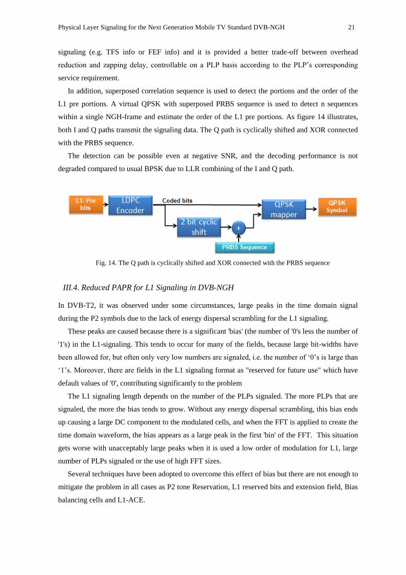
In addition, superposed correlation sequence is used to detect the portions and the order of the
L1 pre portions. A virtual QPSK with superposed PRBS sequence is used to detect n sequences
within a single NGH-frame and estimate the order of the L1 pre portions. As figure 14 illustrates,
both I and Q paths transmit the signaling data. The Q path is cyclically shifted and XOR connected
with the PRBS sequence.
The detection can be possible even at negative SNR, and the decoding performance is not
degraded compared to usual BPSK due to LLR combining of the I and Q path.
Fig. 14. The Q path is cyclically shifted and XOR connected with the PRBS sequence
III.4. Reduced PAPR for L1 Signaling in DVB-NGH
In DVB-T2, it was observed under some circumstances, large peaks in the time domain signal
during the P2 symbols due to the lack of energy dispersal scrambling for the L1 signaling.
These peaks are caused because there is a significant 'bias' (the number of '0's less the number of
'1's) in the L1-signaling. This tends to occur for many of the fields, because large bit-widths have
been allowed for, but often only very low numbers are signaled, i.e. the number of ‗0‘s is large than
‗1‘s. Moreover, there are fields in the L1 signaling format as "reserved for future use" which have
default values of '0', contributing significantly to the problem
The L1 signaling length depends on the number of the PLPs signaled. The more PLPs that are
signaled, the more the bias tends to grow. Without any energy dispersal scrambling, this bias ends
up causing a large DC component to the modulated cells, and when the FFT is applied to create the
time domain waveform, the bias appears as a large peak in the first 'bin' of the FFT. This situation
gets worse with unacceptably large peaks when it is used a low order of modulation for L1, large
number of PLPs signaled or the use of high FFT sizes.
Several techniques have been adopted to overcome this effect of bias but there are not enough to
mitigate the problem in all cases as P2 tone Reservation, L1 reserved bits and extension field, Bias
balancing cells and L1-ACE.

22 Physical Layer Signaling for the Next Generation Mobile TV Standard DVB-
NGH
Nevertheless, DVB-NGH simply adopts a scrambling for the L1 signaling information based on
the mechanism employed to scramble the data. The complete L1 signaling blocks shall be
randomized with a scrambling sequence. The scrambling sequence is generated by the feed-back
shift register, the polynomial for the pseudo random binary sequence (PRBS).
IV. RESULTS AND DISCUSSIONS
IV.1. Capacity Improvements Results
In this section the capacity improvements are studied and compared in both standards, DVB-T2
and DVB-NGH.
DVB-T2
The L1 signaling of DVB-T2 has a limited capacity. There is a maximum number of PLPs that can
be signaled (Num_PLP). The amount of signalling information depends on the number of the PLPs
used in the multiplex. In Appendix A, the different parameters of each field are shown.
As illustrated in Table 3, the L1 pre has a fixed number of bits, 200 bits, and the numbers of bits
of the configurable and dynamic fields of L1 post depend on the number of PLPs signaled. L1 post
configurable has a fixed number of bits, 136 bits, and variable number of bits depending of the PLP
signaled, 89·Num_PLP. In the same way, L1 post dynamic has a fixed number of bits, 79 bits, and
48·Num_PLP variable bits. With L1 repetition, the number of bits of L1 post dynamic will be
double, because there are two fields of L1 post dynamic. To conclude, a 32 bit error detection code
is applied to the entire L1-post.
L1 Pre
L1 Post
Configurable Dynamic CRC
Fixed Variable Fixed Variable
200 136 89·NumPLP 79 48·NumPLP 32
Table 3. L1 Signaling Capacity DVB-T2 (bits).
DVB-NGH
In DVB-NGH, the L1 signaling structure has been optimized and re-structured. The L1 pre has a
fixed number of bits, 280 bits, and the numbers of bits of the configurable and dynamic fields of L1
post depend on the number of PLPs signaled and the PLP configurations signaled. L1 post
configurable has a fixed number of bits, 144 bits, variable number of bits depending of the PLP
signaled and the PLP configurations, 39·Num_PLP and 61·PLP_CONFIG. In the same way, L1-
post dynamic has a fixed number of bits, 76 bits, and 46·Num_PLP variable bits. To conclude, a 32
bit error detection code is applied to the entire L1-post.
Physical Layer Signaling for the Next Generation Mobile TV Standard DVB-NGH 23
L1 Pre
L1 Post
Configurable Dynamic CRC
Fixed Variable PLP Configurations Fixed Variable
280 144 39·NumPLP 61·Num_PLPCONFIG 76 46·NumPLP 32
Table 4. L1 Signaling Capacity DVB-NGH (bits).
L1 signaling structure Comparison: DVB-T2 and DVB-NGH
In both cases, DVB-T2 and DVB-NGH, the number of OFDM symbols used to carry the L1
signaling depends on the FFT size used, the P2 symbols (NP2). The maximum numbers of PLPs are
limited with the available cell in the P2 symbols and the modulation used.
For a bandwidth of 8MHz the FFT used is an 8K (GI 1/4) and the number of P2 symbols for this
FFT mode is 2. In this case, the numbers of available data carries are 6817 for an OFDM symbol,
consequently, the numbers of available cells for signaling are 13634. The case under study is the
most robust way for L1 signaling in both cases (the modulation used is the BPSK).
In DVB-T2, the maximum number of signaled PLPs is determinate by the maximum number of
available cells (13634 cells). L1signaling without any type of robustness the maximum number of
signaled PLP is 34, and with L1 repetition the maximum number is 24 PLPs.
In DVB-NGH, the maximum number of signaled PLPs is determinate by the signaling
information length (KBCH =2100 information bits) and the PLP configurations signaled. The
numbers of maximum PLPs are 21, 20, 19 and 18, for 1, 2, 3 and 4 PLP configurations signaled.
The numbers of cells for L1 pre signaling are 1840 and 1700, for DVB-T2 and DVB-NGH,
respectively.
DVB-T2:
NUM_PLP K_post BCH_FEC Parity Bits Cells_L1_post Signaling Cells
1 384 168 1192 1576 3416
4 795 168 1685 2480 4320
8 1343 168 2343 3686 5526
16 2439 168 3657 6096 7936
24 3535 168 4973 8508 10348
32 4631 168 6287 10918 12758
34 4905 168 6617 11522 13362
DVB-T2 with L1 Repetition:
NUM_PLP K_post BCH_FEC Parity Bits Cells_L1_post Signaling Cells
1 511 168 1343 1854 3694
4 1066 168 2010 3076 4916
8 1806 168 2898 4704 6544
16 3286 168 4674 7960 9800
24 4766 168 6450 11216 13056
24 Physical Layer Signaling for the Next Generation Mobile TV Standard DVB-
NGH
DVB-NGH with 2 PLP Configurations
NUM_PLP K_post BCH_FEC Parity Cells_L1_post Signaling Cells
1 460 60 946 1466 3166
4 714 60 1289 2063 3763
8 1054 60 1748 2862 4562
16 1734 60 2666 4460 6160
20 2074 60 3125 5259 6959
DVB-NGH with 4 PLP Configurations
NUM_PLP K_post BCH_FEC Parity Cells_L1_post Signaling Cells
1 582 60 1111 1753 3453
4 836 60 1454 2350 4050
8 1176 60 1913 3149 4849
16 1856 60 2831 4747 6447
18 2026 60 3061 5147 6847
IV.2. Robustness Improvements Results
In this section results of simulations on the transmission of the physical layer signaling are
presented. The performance of P2 symbol(s) is studied, and later the analysis is extended to include
the L1 signaling robustness mechanisms in the P2 symbol(s) in both technologies, DVB-T2 and
DVB-NGH. The performance has been evaluated in two different channel conditions: AWGN
(Additive White Gaussian Noise) for fixed reception and TU6 (mobile 6-Tap Typical Urban) with
Doppler frequency of 10Hz and 80Hz for mobile reception.
P2 Symbols: Comparative of LDPC codes for L1 signaling
Number of Shortening / Puncturing bits
The shortening and puncturing methods affect the outperformance of L1 signaling. A high number
of shortening and puncturing bits degrade the outperformance. When the puncturing method is
applied, several bits are dropped depending on a Puncturing Pattern, but not all these dropped bits
have the same weight. There are bits more important than others. Consequently, when important
bit-groups are dropped and taking into account the channel transmission, the original information is
difficult to obtain in reception. For that reason, the less important bit-groups are dropped first.
The following table shows, for each LDPC code and depending on the code rate, the
information length for the 4K and 16K LDPC codes, respectively.
Physical Layer Signaling for the Next Generation Mobile TV Standard DVB-NGH 25
L1 Signaling LDPC Codes Code Rate Information bits Parity bits
L1 Pre 4K 1/5 1080 3240
16K 1/5 4000 12000
L1 Post 4K 1/2 2160 2160
16K 4/9 7200 9000
Table 5. 4K Codes vs 16K Codes
The L1 signaling length depends on the PLPs signaled and the L1 signaling format applied,
NGH or T2.The L1 signaling headers in NGH have been optimized and the shrunk size of 4K
LDPC codes is more suitable for signaling, and considerably, reduces the amount of shortening and
puncturing methods.
For a given number of PLP, 8 PLPS, the numbers of shortening/puncturing bits are 924/247 and
5689/6825, respectively. The following table can be observed the number of shortening /puncturing
bits for different numbers of PLP signaled. The number of PLP configurations signaled in NGH is
4.
L1
Signaling
LDPC
Codes
Code
Rate
Num
PLP
NGH L1
Signaling
BCH
FEC
Shortening
bits
Puncturing
bits
L1 Pre 4K 1/5 - 280 60 740 1880
L1 Post
4K 1/2 1 582 60 1518 1049
4K 1/2 4 836 60 1264 706
4K 1/2 8 1176 60 924 247
8K* 1/4 16 1856 60 244 3649*
8K* 1/4 18 2026 60 74 3419*
L1 Signaling LDPC
Codes
Code
Rate Num PLP
T2 L1
Signaling
BCH
FEC
Shortening
bits
Puncturing
bits
L1 Pre 16K 1/5 - 200 168 3632 10456
L1 Post
16K 4/9 1 384 168 6648 7976
16K 4/9 4 795 168 6237 7483
16K 4/9 8 1343 168 5689 6825
16K 4/9 16 2439 168 4593 5511
16K 4/9 24 3535 168 3497 4195
16K 4/9 32 4631 168 2401 2881
Table 6. 4K Codes vs 16K Codes
At the following points, the degradation of the 16K/4K LDPC codes depending on the number
of PLPs is compared and studied. The channel used for the study is the AWGN channel.
26 Physical Layer Signaling for the Next Generation Mobile TV Standard DVB-
NGH
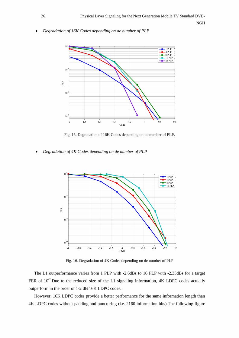
Degradation of 16K Codes depending on de number of PLP
Fig. 15. Degradation of 16K Codes depending on de number of PLP.
Degradation of 4K Codes depending on de number of PLP
Fig. 16. Degradation of 4K Codes depending on de number of PLP
The L1 outperformance varies from 1 PLP with -2.6dBs to 16 PLP with -2.35dBs for a target
FER of 10-2
.Due to the reduced size of the L1 signaling information, 4K LDPC codes actually
outperform in the order of 1-2 dB 16K LDPC codes.
However, 16K LDPC codes provide a better performance for the same information length than
4K LDPC codes without padding and puncturing (i.e. 2160 information bits).The following figure

Physical Layer Signaling for the Next Generation Mobile TV Standard DVB-NGH 27
shows the performance of 16K and 4K LDPC codes for 2160 information bits. Figure 17 shows a
better performance of 16K codes around ~0.7dB for this case.
Fig. 17. Performance16K / 4K LDPC Codes without Shortening/Puncturing methods (2160 bits)
Benefits of 4K LDPC codes
4K LDPC codes have a significant gain (1-2 dBs) and much less power consumption thanks to
significantly smaller number of shortening and puncturing. While the 16k LDPC code requires
more than 50 iterations to converse, the 4k LDPC code converse with only 25 even less complex
iterations (Figure 18). This significantly faster convergence speed is essential for serial coding
operation for signaling. Finally the reduced size of the L1 signaling information, 4K LDPC codes
actually outperform in the order of 1-2 dB 16K LDPC codes.
Fig. 18. Number of iterations 4K LDPC Codes Vs 16K LDPC Codes (Info = 680 bits, CNR=0dBs)
-3.3 -3.1 -2.9 -2.7 -2.5 -2.3 -2.1 -1.9 -1.7 -1.510
-4
10-3
10-2
10-1
100
CNR
FE
R
16K LDPC Code
4K LDPC Code
10 15 20 25 30 35 40 45 5010
-4
10-3
10-2
10-1
100
Number of Iterations
FE
R
4K LDPC
16K LDPC

28 Physical Layer Signaling for the Next Generation Mobile TV Standard DVB-
NGH
L1 Robustness Mechanisms
DVB-T2:
L1 repetition
The performance of L1 signaling is enhanced by the use of L1 signaling repetition mechanism. The
simulation results for the TU6 channel with Doppler frequency of 10 and 80 Hz for 8 PLPs are
present in the following figures. The modulation scheme used is the most robust modulation, the
BPSK. For TU6 the performance of the L1 signaling is way worse than for the static channels. The
weak performance is due to the lack of time diversity for L1 signaling as it is spread over only the
two P2 symbols in 8k case.
When using repetition, it is assumed that any time two subsequent preambles are not lost, the
reception of PLPs can continue without interruptions. This assumption is justified, because the L1-
post dynamic information that is repeated is the most important for the receiver to be correct as it
can change from T2 frame to T2 frame while the configurable information changes rather seldom
and thus does not necessarily need to be correctly received from every T2 frame.
The L1 repetition is represented at the figures with red color, and it can be observed when L1
repetition mechanism is used the outperformance gains of 2 and 3dB‘s for Doppler of 80 and 10Hz,
respectively.
Channel
TU6 (fd=10Hz) TU6 (fd=80Hz)
Robustness Type FER (10-2
) Gain(dB) FER (10-2
) Gain(dB)
L1 6.5 - 5.73 -
L1 Rep. T2 3.62 2.88 3.45 2.28
Table 7. Gain obtained with L1 Repetition
Fig. 19. L1 repetition mechanism in TU6 channel with fd=80Hz

Physical Layer Signaling for the Next Generation Mobile TV Standard DVB-NGH 29
Fig. 20. L1 repetition mechanism in TU6 channel with fd=10Hz
DVB-NGH:
DVB-NGH improves L1 signaling robustness from DVB-T2 by adopting several mechanisms.
These mechanisms enhance the L1 signaling robustness by getting more time diversity in the
signal, as Additional Parity and Incremental Redundancy methods. These new techniques obtain a
better performance in comparison with just repeating the information in the frame (L1-repetition).
Additional Parity
The main advantage of using AP is that the effective coding rate for L1 signalling can be reduced
without any LDPC matrix. The following table shows the effective code rate achieved for different
configurations with parameter K=0.35 (K_sig = K_post+BCH FEC).
Num
PLP K_sig
Parity
bits
AP (bits) Code Rate Achieved
AP
Ratio
{1}
AP
Ratio
{2}
AP
Ratio
{3}
AP
Ratio
{0}
AP
Ratio
{1}
AP
Ratio
{2}
AP
Ratio
{3}
1 642 1111 388 776 1164 0.3662 0.2999 0.2539 0.2201
4 896 1454 508 1016 1524 0.3813 0.3135 0.2662 0.2313
8 1236 1913 668 1336 2004 0.3925 0.3238 0.2756 0.2399
16 1916 2831 990 1980 2970 0.4036 0.3340 0.2848 0.2483
Table 8. Additional Parity benefits
The following table shows the gain achieved between the configuration without using the
Additional Parity mechanism and the different configurations of this mechanism with different
lengths AP1, AP2 and AP3, respectively for 8 PLP signalled with 4 PLP configurations.
Channel
TU6 (fd=10Hz) TU6 (fd=80Hz)
Additional
Parity
Configuration
FER (10-2
) Gain(dB) FER (10-2
) Gain(dB)
L1 - AP0 4.32 - 3.96 -
AP1 3.19 1.13 2.37 1.59
AP2 2.29 2.03 1.37 2.59
AP3 1.52 2.80 0.51 3.45
Table 9. Gain obtained with Additional Parity

30 Physical Layer Signaling for the Next Generation Mobile TV Standard DVB-
NGH
Fig. 21. Additional Parity mechanism with different length configurations {0,1,2,3} in Channel TU6 with
fd=80Hz
Fig. 22. Additional Parity mechanism with different length configurations {0,1,2,3} in Channel TU6 with
fd=10Hz
Incremental Redundancy
The Incremental Redundancy technique is used to extend this new 4k LDPC codes with additional
parity bits (another 4k code word) to provide additional robustness when are required. IR uses
special 8K LDPC codes (8640 bits) for coding L1 signaling information bits. These bits are used to
reduce the code rate from 1/2 to 1/4 (Code Rate Control technique), and especially, when
Additional Parity mechanism needs more parity bits than the punctured bits.
Physical Layer Signaling for the Next Generation Mobile TV Standard DVB-NGH 31
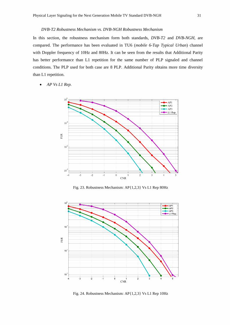
DVB-T2 Robustness Mechanism vs. DVB-NGH Robustness Mechanism
In this section, the robustness mechanism form both standards, DVB-T2 and DVB-NGH, are
compared. The performance has been evaluated in TU6 (mobile 6-Tap Typical Urban) channel
with Doppler frequency of 10Hz and 80Hz. It can be seen from the results that Additional Parity
has better performance than L1 repetition for the same number of PLP signaled and channel
conditions. The PLP used for both case are 8 PLP. Additional Parity obtains more time diversity
than L1 repetition.
AP Vs L1 Rep.
Fig. 23. Robustness Mechanism: AP{1,2,3} Vs L1 Rep 80Hz
Fig. 24. Robustness Mechanism: AP{1,2,3} Vs L1 Rep 10Hz
32 Physical Layer Signaling for the Next Generation Mobile TV Standard DVB-
NGH
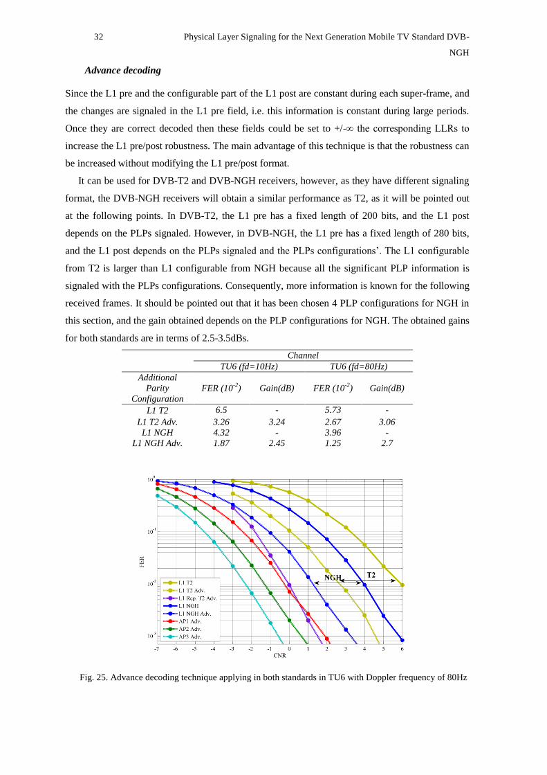
Advance decoding
Since the L1 pre and the configurable part of the L1 post are constant during each super-frame, and
the changes are signaled in the L1 pre field, i.e. this information is constant during large periods.
Once they are correct decoded then these fields could be set to +/-∞ the corresponding LLRs to
increase the L1 pre/post robustness. The main advantage of this technique is that the robustness can
be increased without modifying the L1 pre/post format.
It can be used for DVB-T2 and DVB-NGH receivers, however, as they have different signaling
format, the DVB-NGH receivers will obtain a similar performance as T2, as it will be pointed out
at the following points. In DVB-T2, the L1 pre has a fixed length of 200 bits, and the L1 post
depends on the PLPs signaled. However, in DVB-NGH, the L1 pre has a fixed length of 280 bits,
and the L1 post depends on the PLPs signaled and the PLPs configurations‘. The L1 configurable
from T2 is larger than L1 configurable from NGH because all the significant PLP information is
signaled with the PLPs configurations. Consequently, more information is known for the following
received frames. It should be pointed out that it has been chosen 4 PLP configurations for NGH in
this section, and the gain obtained depends on the PLP configurations for NGH. The obtained gains
for both standards are in terms of 2.5-3.5dBs.
Channel
TU6 (fd=10Hz) TU6 (fd=80Hz)
Additional
Parity
Configuration
FER (10-2
) Gain(dB) FER (10-2
) Gain(dB)
L1 T2 6.5 - 5.73 -
L1 T2 Adv. 3.26 3.24 2.67 3.06
L1 NGH 4.32 - 3.96 -
L1 NGH Adv. 1.87 2.45 1.25 2.7
Fig. 25. Advance decoding technique applying in both standards in TU6 with Doppler frequency of 80Hz
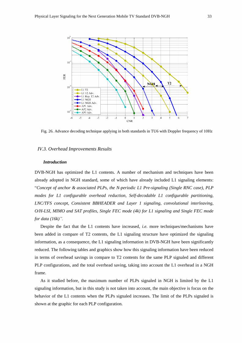
Physical Layer Signaling for the Next Generation Mobile TV Standard DVB-NGH 33
Fig. 26. Advance decoding technique applying in both standards in TU6 with Doppler frequency of 10Hz
IV.3. Overhead Improvements Results
Introduction
DVB-NGH has optimized the L1 contents. A number of mechanism and techniques have been
already adopted in NGH standard, some of which have already included L1 signaling elements:
―Concept of anchor & associated PLPs, the N-periodic L1 Pre-signaling (Single RNC case), PLP
modes for L1 configurable overhead reduction, Self-decodable L1 configurable partitioning,
LNC/TFS concept, Consistent BBHEADER and Layer 1 signaling, convolutional interleaving,
O/H-LSI, MIMO and SAT profiles, Single FEC mode (4k) for L1 signaling and Single FEC mode
for data (16k)”.
Despite the fact that the L1 contents have increased, i.e. more techniques/mechanisms have
been added in compare of T2 contents, the L1 signaling structure have optimized the signaling
information, as a consequence, the L1 signaling information in DVB-NGH have been significantly
reduced. The following tables and graphics show how this signaling information have been reduced
in terms of overhead savings in compare to T2 contents for the same PLP signaled and different
PLP configurations, and the total overhead saving, taking into account the L1 overhead in a NGH
frame.
As it studied before, the maximum number of PLPs signaled in NGH is limited by the L1
signaling information, but in this study is not taken into account, the main objective is focus on the
behavior of the L1 contents when the PLPs signaled increases. The limit of the PLPs signaled is
shown at the graphic for each PLP configuration.

34 Physical Layer Signaling for the Next Generation Mobile TV Standard DVB-
NGH
Signaling Reduction Comparison
2 PLP Configurations
Num PLP T2 NGH
K_Post L1_Config. L1_Dyn. K_Post L1_Config. L1_Dyn.
1 384 225 127 460 305 122
4 795 492 271 714 422 260
8 1343 848 463 1054 578 444
16 2439 1560 847 1734 890 812
24* 3535 2272 1231 2414* 1202* 1180*
32* 4631 2984 1615 3094* 1514* 1548*
Num PLP
Overhead Savings Total Overhead Savings
K_Post L1_Config. L1_Dyn. L1 Signaling Cells /
NGH Frame Cells
1 -1.6411% -2.6810% 0.3096% 0.2175%
4 1.7491% 2.3458% 0.6811% 0.2567%
8 6.2406% 9.0483% 1.1765% 0.3093%
16 15.2235% 22.4531% 2.1672% 0.4144%
24* 24.2064% 35.8579% 3.1579% 0.5195%
32* 33.1894% 49.2627% 4.1486% 0.6247%
4 PLP Configurations
Num PLP T2 NGH
K_Post L1_Config. L1_Dyn. K_Post L1_Config. L1_Dyn.
1 384 225 127 582 427 122
4 795 492 271 836 544 260
8 1343 848 463 1176 700 444
16 2439 1560 847 1856 1012 812
24 3535 2272 1231 2536* 1324* 1180*
32 4631 2984 1615 3216* 1636* 1548*
Num PLP
Overhead Savings Total Overhead Savings
K_Post L1_Config. L1_Dyn. L1 Signaling Cells /
NGH Frame Cells
1 -4.2755% -6.7694% 0.3096% 0.2364%
4 -0.8853% -1.7426% 0.6811% 0.2756%
8 3.6061% 4.9598% 1.1765% 0.3282%
16 12.5891% 18.3646% 2.1672% 0.4333%
24* 21.5720% 31.7694% 3.1579% 0.5384%
32* 30.5550% 45.1743% 4.1486% 0.6435%

Physical Layer Signaling for the Next Generation Mobile TV Standard DVB-NGH 35
Fig. 27. Signaling Contents Comparison for different number of PLPs
0 2 4 6 8 10 12 14 16 18 20 22 24 26 28 30 32 340
500
1000
1500
2000
2500
3000
3500
4000
4500
5000
Num PLP
Nu
m B
its
NGH 4PLP Config
NGH 2PLP Config.
T2

36 Physical Layer Signaling for the Next Generation Mobile TV Standard DVB-
NGH
V. OPTIMIZATION OF THE PHYSICAL LAYER SIGNALING CONFIGURATION FOR THE
DATA PATH CONFIGURATION
In this section, results of simulations on the transmission of the physical layer signaling and data
path are presented. First, the performance has been evaluated for the two different technologies.
The L1 signaling obtained results are comparable to the data path. For both standards, the data
paths have been designed with different types of robustness, the most robust type for data are
QPSK 1/2 and QPSK 1/3, respectively. The main point of this section is focus on seeing the
advantages and improvements of the L1 signaling make more robust the signaling than the data
path in mobile conditions, and on the other hand, checking the most suitable L1 configuration or
the possible configurations for the different channel conditions.
For the DVB-T2, for mobile channel conditions the data path is more robust than the signaling
path. In [3] the performance of the data path for different configurations of inter-frame interleaving
is illustrated for TU6 channel with Doppler of 80 and 10Hz. In this case, the CNR achieved at BB
FER 1% (dB) are 2.5 and 3, respectively.
According to the signaling results with the same simulations conditions, the CNR achieved at
FER 1% for L1 signaling (Fig 19 and 20) are 5.7 and 6.7., respectively. Consequently for TU-6, it
is observed that if QPSK modulation with code rate 1/2 is used for data, the L1 signaling
transmitted in the preambles cannot be configured to be 3 dB more robust than the data. In this
situation the signaling may introduce a bottleneck for the performance of the system.
The robustness mechanism (L1 repetition) makes more robust the signaling path, the CNR
achieved at FER 1% for L1 signaling with repetition (Fig 19 and 20) are 3.45 and 3.62,
respectively, but it is not robustness enough to overcome this situation. However, with the advance
decoding mechanism the L1 signaling overcome this adverse situation and makes the signaling
path more robust than the data path with L1 repetition. The CNR achieved without L1 repetition
applying advance decoding at FER 1% for L1 signaling are 2.5 and 3.2 for 80 and 10Hz,
respectively. Nevertheless if L1 repetition is applied with advance decoding the CNR achieved in
this situation at FER 1% are 0 and 0.5 for 80 and 10Hz, respectively.
Consequently, if advance decoding with L1 repetition are applied in DVB-T2, the signaling path
is more or less 2.5 dBs more robust than the data path. The gain achieved with all the robustness
methods have done the L1 signaling almost 6dBs more robust than the L1 signaling without any
type of robustness.
In DVB-NGH the most robust data path is created more robust than T2 data path, in this case
QPSK 1/3. At the following figure, it is shown the performance of code rates 1/3 and 2/5 in the
configuration of SISO and SIMO, with frame interval 5 and frame length 50 ms. The channel used
is the TU6 with a Doppler frequency of 80Hz. The CNR achieved at BB FER 1% (dB) for the
performance of the data path is 1.3dBs [2]
Physical Layer Signaling for the Next Generation Mobile TV Standard DVB-NGH 37
According to the NGH signaling results with the same simulations conditions, the CNR
achieved at FER 1% for L1 signaling (Fig 21) is 3.96dBs for 80Hz. The L1 signaling is further
more robust than T2 L1 signaling without any type of robustness mechanism.
NGH has created the Additional Parity mechanism joint with the Incremental Redundancy
mechanism to overcome adverse situation in mobile reception creating more time interleaving. The
gain obtained with these mechanisms depends on the configuration used. The gains achieved are
1.6, 2.6 and 3.45dBs for 1, 2, 3 AP configurations, respectively. The CNR achieved at FER 1% for
L1 signaling with AP/IR are 2.37, 1.37 and 0.51dBs for 1, 2, 3 AP configurations, respectively.
Moreover, the advance decoding makes the L1 signaling in NGH robust enough for this type of
mobile environment reception, getting a gain of 2.5-3dBs. In this case the CNR achieved at FER
1% for L1 signaling with AP/IR and Advance Decoding technique are 1.25, -0.84, -1.33 and -2.34
dBs for 0,1, 2, 3 AP configurations, respectively
Consequently, if advance decoding with AP/IR are applied in DVB-NGH, the signaling path are
0.05, 2.14, 2.63, 3.64dBs more robust than the data path depending on the AP configuration used.
The gain achieved with all the robustness methods have done the L1 signaling almost 6.5dBs more
robust.

38 Physical Layer Signaling for the Next Generation Mobile TV Standard DVB-
NGH
VI. CONCLUSIONS
In this thesis provides an overview of the physical layer signaling in the new generation mobile
broadcasting DVB-NGH standard. The thesis takes as a starter point the physical layer of DVB-T2
and, studies and compares all the advantages and improvements given by the new physical layer of
DVB-NGH for mobile conditions. Four different aspects have been studied and investigated: the
transmission robustness, the reduced signaling overhead, the increment in signaling capacity and
the reduced peak-to-average power ratio in DVB-NGH.
The L1 signaling structure has been optimized and re-structured. In DVB-T2, the maximum
number of signaled PLPs is determinate by the maximum number of available cells in the P2
symbol(s). In DVB-NGH, the maximum number of signaled PLPs is determinate by the signaling
information length (KBCH =2100 information bits) and the PLP configurations signaled for the new
4K LDPC codes.
Moreover, DVB-NGH has optimized the L1 contents. Despite the fact that the L1 contents have
increased in NGH, i.e. more techniques/mechanisms have been added in compare of T2 contents,
the L1 signaling structure have optimized the signaling information. Instead of signaling the
configuration of each PLP, PLPs are associated in groups with the same settings, reducing the
required L1 signaling information. Furthermore, it is possible to split in several frames signaling
parameters which are in practice static, and which are transmitted in DVB-T2 in every frame. As a
consequence, the L1 signaling information in DVB-NGH has been significantly reduced in terms of
25%.
Regarding to the robustness, the new mini 4K LDPC adopted and its reduce size is more
suitable for the L1 signaling because reduces the amount of shortening and puncturing. It has been
reduced in considerably, for 8 PLPs the numbers of shortening/puncturing bits are 924/247 and
5689/6825, respectively. Moreover 4K LDPC codes have a significant gain (1-2 dBs) and much
less power consumption thanks to significantly smaller number of shortening and puncturing.
Consequently less iterations are needed to converge, 25even less complex iterations than the 16K
LDPC.
The two mechanisms adopted, Incremental Redundancy and Additional Parity in DVB-NGH
has better outperformance than the L1 repetition mechanism of DVB-T2. The gain obtained with
AP/IR method is in terms of 2-3dBs more robust than L1 repetition. In addition, with the advance
decoding, it can be obtained a better outperformance, with gains of 3-4dB‘s depending on the PLP
configuration used. Consequently, joining the robustness mechanism and the advance decoding, it
can be obtained a gain of 6-7dB‘s in mobile conditions.

Physical Layer Signaling for the Next Generation Mobile TV Standard DVB-NGH 39
Finally, from the results and the performance evaluation, it can be said the signaling path could
be more robust than the data path with the most robust configuration in mobile transmissions. The
main point is focused on determine the more suitable L1 configuration to make more robust the L1
signaling than the data path for the channel conditions.
ACKNOWLEDGMENTS
This thesis has been developed under the European Celtic ENGINES (Enabling Next
Generation Networks for Broadcast Services) project, reference project in terms of digital
television. The ENGINES project forms a task force to develop the Next Generation Broadcasting
standards and their implementation for Fixed Portable, Mobile and Handheld reception. The project
works both on technical proposals for Digital Video Broadcasting project as well as on efficient
usage of the latest version of the standards. The project will also generate a PanLab framework for
a common lab and field infrastructure mainly for DVB but also for other standards.
Oh the other hand, I would like to thanks to David Gómez Barquero for his support at this thesis
development and his help since I came to the MCG and all may mates at the MCG, because they
are so good mates. I am very grateful to Narcís Cardona for giving me the possibility to take part of
his research group.
And finally, but not less important, I would like to give my sincere thanks to my family and my
girlfriend Carmen, because they have been made reality all I have achieved so far and the person I
am nowadays.
REFERENCES
[1] EN 302 755 V1.1.1, ―Frame structure channel coding and modulation for a second generation digital
terrestrial television broadcasting system (DVB-T2)‖, September 2009
[2] DVB Blue Book A133 ―Implementation guidelines for a second generation digital terrestrial television
broadcasting system (DVB-T2) (draft TR 102 831 V1.1.1) ―, February 2009
[3] D. Gómez-Barquero, D. Gozálvez and N. Cardona, “Time Diversity in Mobile DVB-T2 Systems,” IEEE
Trans. on Broadcasting, vol. 57, no. 7, pp. 617-628, 2011.
[4] T. Jokela, M. Tupala, and J. Paavola, “Analysis of Physical Layer Signaling Transmission in DVB-T2
Systems”, IEEE Trans. on Broadcasting, vol. 53, no. 3, pp. 410-417, 2010.
[5] T. Jokela and J. Paavola, “Robustness analysis of physical layer signaling transmission in DVB-T2,‖ in
Proc. IEEE Int. Symp. Broadband Multimedia Syst. Broadcast., May 2009.
[6] D. Gómez-Barquero, D.E. Vargas, P.F. Gómez, J.M. Llorca, C. Romero and N. Cardona, ―DVB-NGH,
la Nueva Generación de Televisión Digital Móvil‖, Jornadas Telecom I+D 2011.
[7] Jan Zöllne. “Continuous_N_periodic_L1_sul”, TM-NGH 795, DVB Forum.
[8] Jan Zöllne. “L1-Pre performance with NGH signaling PLP”, TM-NGH 866, DVB Forum.
40 Physical Layer Signaling for the Next Generation Mobile TV Standard DVB-
NGH
[9] Erik Stare. “Reduced overhead for L1-config and L1-dynamic” TM-NGH 843, DVB Forum.
[10] Ismael Gutiérrez. “L1 Signaling Optimization”, TM-NGH 875, DVB Forum.
[11] J. Zöellner, “Further Considerations on n-periodic Transmission of L1-pre and L1-config”, DVB Forum
17.05.2011
[12] , Hognsil Jeong. “Puncturing Patterns for 4k codes with AP/IR”, TM-NGH 1263, DVB Forum.
[13] Hognsil Jeong. “PF72 4k codes for L1 signaling”, TM-NGH 1159r1, DVB Forum.
[14] SAMSUNG. “4K LDPC Codes for DVB-NGH System”, TM-NGH 1159r1, DVB Forum.
[15] Ismael Gutiérrez. “L1 Signaling Robustness”, TM-NGH 884, DVB Forum.
[16] Alain Mourad ―L1 signalling - V1.0 ‖, TM-NGH1366, DVB Forum.
[17] Woo-Suk Ko. ―P1/aP1 preamble‖, TM-NGH1156, DVB Forum.
[18] C. Nokes, A. Morellos ―NGH T2 compatibility CfT response‖, TM-NGH075, DVB Forum