Embed Size (px)
Citation preview
A product of a PHYTEC Technology Holding company
phyBOARD®-Subra-i.MX 6
Application Guide
Document No.: L-794e_0
SBC Prod. No..: PB-00601-xxx
CB PCB No.: 1394.1 SOM PCB No.: 1362.2
Edition: February 2014

phyBOARD-Subra-i.MX 6 [PB-00601-xxx]
© PHYTEC Messtechnik GmbH 2014 L-794e_0
Copyrighted products are not explicitly indicated in this manual. The absence of the trademark (™, or ®) and copyright (©) symbols does not imply that a product is not protected. Additionally, registered patents and trademarks are similarly not expressly indicated in this manual. The information in this document has been carefully checked and is considered to be entirely reliable. However, PHYTEC Messtechnik GmbH assumes no responsibility for any inaccuracies. PHYTEC Messtechnik GmbH neither gives any guarantee nor accepts any liability whatsoever for consequential damages resulting from the use of this manual or its associated product. PHYTEC Messtechnik GmbH reserves the right to alter the information contained herein without prior notification and accepts no responsibility for any damages that might result. Additionally, PHYTEC Messtechnik GmbH offers no guarantee nor accepts any liability for damages arising from the improper usage or improper installation of the hardware or software. PHYTEC Messtechnik GmbH further reserves the right to alter the layout and/or design of the hardware without prior notification and accepts no liability for doing so. © Copyright 2014 PHYTEC Messtechnik GmbH, D-55129 Mainz. Rights - including those of translation, reprint, broadcast, photomechanical or similar reproduction and storage or processing in computer systems, in whole or in part - are reserved. No reproduction may occur without the express written consent from PHYTEC Messtechnik GmbH. EUROPE NORTH AMERICA
Address: PHYTEC Messtechnik GmbH Robert-Koch-Str. 39 D-55129 Mainz GERMANY
PHYTEC America LLC 203 Parfitt Way SW, Suite G100 Bainbridge Island, WA 98110 USA
Ordering Information:
+49 (6131) 9221-32 [email protected]
1 (800) 278-9913 [email protected]
Technical Support:
+49 (6131) 9221-31 [email protected]
1 (800) 278-9913 [email protected]
Fax: +49 (6131) 9221-33 1 (206) 780-9135
Web Site: http://www.phytec.de http://www.phytec.eu http://www.phytec.com
Preliminary Edition February 2014
Contents
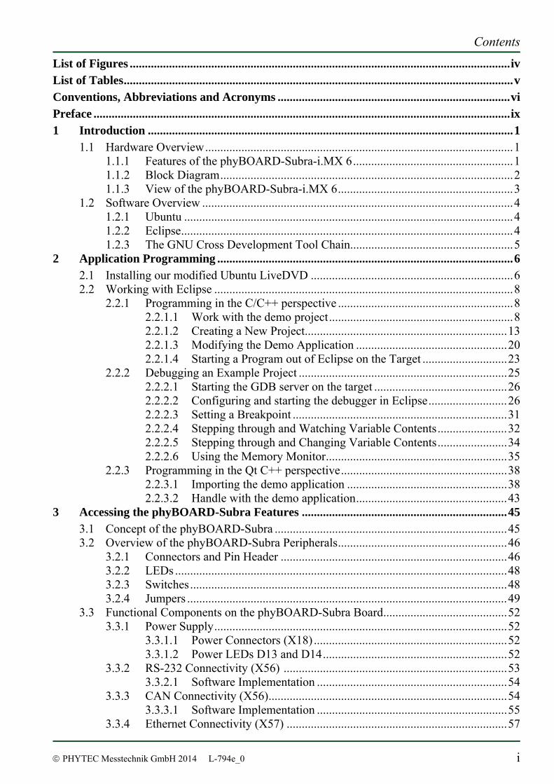
© PHYTEC Messtechnik GmbH 2014 L-794e_0 i
List of Figures ..............................................................................................................................iv List of Tables.................................................................................................................................v Conventions, Abbreviations and Acronyms .............................................................................vi Preface ..........................................................................................................................................ix 1 Introduction .........................................................................................................................1
1.1 Hardware Overview......................................................................................................1 1.1.1 Features of the phyBOARD-Subra-i.MX 6.....................................................1 1.1.2 Block Diagram.................................................................................................2 1.1.3 View of the phyBOARD-Subra-i.MX 6..........................................................3
1.2 Software Overview .......................................................................................................4 1.2.1 Ubuntu .............................................................................................................4 1.2.2 Eclipse..............................................................................................................4 1.2.3 The GNU Cross Development Tool Chain......................................................5
2 Application Programming ..................................................................................................6 2.1 Installing our modified Ubuntu LiveDVD ...................................................................6 2.2 Working with Eclipse ...................................................................................................8
2.2.1 Programming in the C/C++ perspective ..........................................................8 2.2.1.1 Work with the demo project.............................................................8 2.2.1.2 Creating a New Project...................................................................13 2.2.1.3 Modifying the Demo Application ..................................................20 2.2.1.4 Starting a Program out of Eclipse on the Target ............................23
2.2.2 Debugging an Example Project .....................................................................25 2.2.2.1 Starting the GDB server on the target ............................................26 2.2.2.2 Configuring and starting the debugger in Eclipse..........................26 2.2.2.3 Setting a Breakpoint .......................................................................31 2.2.2.4 Stepping through and Watching Variable Contents.......................32 2.2.2.5 Stepping through and Changing Variable Contents.......................34 2.2.2.6 Using the Memory Monitor............................................................35
2.2.3 Programming in the Qt C++ perspective.......................................................38 2.2.3.1 Importing the demo application .....................................................38 2.2.3.2 Handle with the demo application..................................................43
3 Accessing the phyBOARD-Subra Features ....................................................................45 3.1 Concept of the phyBOARD-Subra .............................................................................45 3.2 Overview of the phyBOARD-Subra Peripherals........................................................46
3.2.1 Connectors and Pin Header ...........................................................................46 3.2.2 LEDs ..............................................................................................................48 3.2.3 Switches.........................................................................................................48 3.2.4 Jumpers ..........................................................................................................49
3.3 Functional Components on the phyBOARD-Subra Board.........................................52 3.3.1 Power Supply.................................................................................................52
3.3.1.1 Power Connectors (X18) ................................................................52 3.3.1.2 Power LEDs D13 and D14.............................................................52
3.3.2 RS-232 Connectivity (X56) ..........................................................................53 3.3.2.1 Software Implementation ...............................................................54
3.3.3 CAN Connectivity (X56)...............................................................................54 3.3.3.1 Software Implementation ...............................................................55
3.3.4 Ethernet Connectivity (X57) .........................................................................57
phyBOARD-Subra-i.MX 6 [PB-00601-xxx]
ii © PHYTEC Messtechnik GmbH 2014 L-794e_0
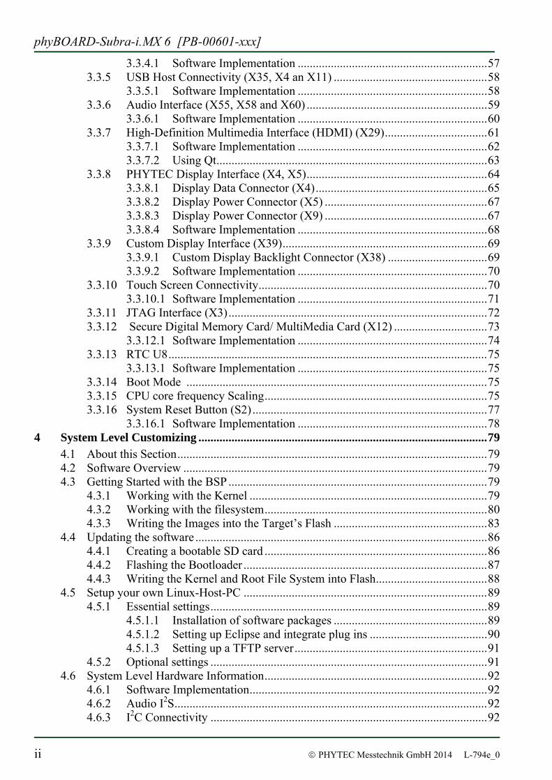
3.3.4.1 Software Implementation ...............................................................57 3.3.5 USB Host Connectivity (X35, X4 an X11) ...................................................58
3.3.5.1 Software Implementation ...............................................................58 3.3.6 Audio Interface (X55, X58 and X60) ............................................................59
3.3.6.1 Software Implementation ...............................................................60 3.3.7 High-Definition Multimedia Interface (HDMI) (X29)..................................61
3.3.7.1 Software Implementation ...............................................................62 3.3.7.2 Using Qt..........................................................................................63
3.3.8 PHYTEC Display Interface (X4, X5)............................................................64 3.3.8.1 Display Data Connector (X4).........................................................65 3.3.8.2 Display Power Connector (X5) ......................................................67 3.3.8.3 Display Power Connector (X9) ......................................................67 3.3.8.4 Software Implementation ...............................................................68
3.3.9 Custom Display Interface (X39)....................................................................69 3.3.9.1 Custom Display Backlight Connector (X38) .................................69 3.3.9.2 Software Implementation ...............................................................70
3.3.10 Touch Screen Connectivity............................................................................70 3.3.10.1 Software Implementation ...............................................................71
3.3.11 JTAG Interface (X3)......................................................................................72 3.3.12 Secure Digital Memory Card/ MultiMedia Card (X12) ...............................73
3.3.12.1 Software Implementation ...............................................................74 3.3.13 RTC U8..........................................................................................................75
3.3.13.1 Software Implementation ...............................................................75 3.3.14 Boot Mode ....................................................................................................75 3.3.15 CPU core frequency Scaling..........................................................................75 3.3.16 System Reset Button (S2) ..............................................................................77
3.3.16.1 Software Implementation ...............................................................78 4 System Level Customizing ................................................................................................79
4.1 About this Section.......................................................................................................79 4.2 Software Overview .....................................................................................................79 4.3 Getting Started with the BSP ......................................................................................79
4.3.1 Working with the Kernel ...............................................................................79 4.3.2 Working with the filesystem..........................................................................80 4.3.3 Writing the Images into the Target’s Flash ...................................................83
4.4 Updating the software .................................................................................................86 4.4.1 Creating a bootable SD card ..........................................................................86 4.4.2 Flashing the Bootloader .................................................................................87 4.4.3 Writing the Kernel and Root File System into Flash.....................................88
4.5 Setup your own Linux-Host-PC .................................................................................89 4.5.1 Essential settings............................................................................................89
4.5.1.1 Installation of software packages ...................................................89 4.5.1.2 Setting up Eclipse and integrate plug ins .......................................90 4.5.1.3 Setting up a TFTP server................................................................91
4.5.2 Optional settings ............................................................................................91 4.6 System Level Hardware Information..........................................................................92
4.6.1 Software Implementation...............................................................................92 4.6.2 Audio I2S........................................................................................................92 4.6.3 I2C Connectivity ............................................................................................92
Contents
© PHYTEC Messtechnik GmbH 2014 L-794e_0 iii
4.6.4 Expansion connector (X13) ...........................................................................93 4.6.4.1 Software Implementation SPI and I2C Connectivity......................94 4.6.4.2 Software Implementation UART Connectivity..............................95 4.6.4.3 Software Implementation SD card Connectivity ...........................95
5 Revision History.................................................................................................................96 Index ............................................................................................................................................97
phyBOARD-Subra-i.MX 6 [PB-00601-xxx]
iv © PHYTEC Messtechnik GmbH 2014 L-794e_0
List of Figures Figure 1: Block Diagram of the phyBOARD-Subra-i.MX 6.....................................................2
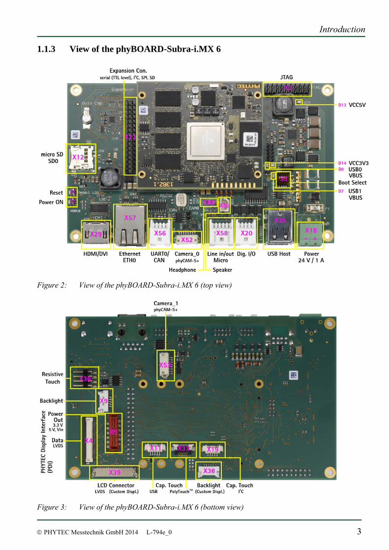
Figure 2: View of the phyBOARD-Subra-i.MX 6 (top view) ...................................................3
Figure 3: View of the phyBOARD-Subra-i.MX 6 (bottom view) .............................................3
Figure 4: Typical Jumper Numbering Scheme ........................................................................49
Figure 5: Power Supply Connectors.........................................................................................52
Figure 6: RS-232 Interface Connector X56 .............................................................................53
Figure 7: RS-232 Connector Signal Mapping..........................................................................53
Figure 8: Components supporting the CAN Interface .............................................................54
Figure 9: CAN Connector Signal Mapping..............................................................................55
Figure 10: Ethernet Interfaces at Connectors X57.....................................................................57
Figure 11: Components supporting the USB Interfaces ............................................................58
Figure 12: Audio Interfaces at Connectors X55, X58 and X60.................................................59
Figure 13: PHYTEC Display Interface Connectors X4, X5 and X9 ........................................64
Figure 14: Touch Screen Connectors X36 .................................................................................70
Figure 15: Touch Screen Connectors X11, X19, X33 ...............................................................71
Figure 16: PHYTEC Display Interface Connectors X4, X5 and X9 ........................................72
Figure 17: SD / MM Card interface at connector X11...............................................................73
The exact choosen boot mode in the processor is SYSBOOT[4:0] = 10011b : NAND, NANDI2C, MMC0, UART0 ....................................................................................75
Contents
© PHYTEC Messtechnik GmbH 2014 L-794e_0 v
List of Tables Table 1: Abbreviations and Acronyms used in this Manual...................................................vii Table 2: phyBOARD-Subra Connectors and Pin Headers .....................................................47
Table 3: phyBOARD-Subra LEDs Descriptions....................................................................48
Table 4: phyBOARD-Subra Push Buttons Descriptions ........................................................48
Table 5: phyBOARD-Subra Jumper Descriptions .................................................................50
Table 6: Pin Assignment of RS-232 Connector X56..............................................................53
Table 7: Pin Assignment of the CAN Interface at Connector X56 ........................................54
Table 8: HDMI/DVI Connector X40 Pinout ..........................................................................61
Table 9: Display Data Connector Signal Description.............................................................65
Table 10: Auxiliary Interfaces at PDI Data Connector X4.......................................................66
Table 11: PDI Power Connector X5 Signal Description ..........................................................67
Table 12: Display Power Connector X9 Signal Description ....................................................67
Table 13: Custom Display Connector Signal Description X39................................................69
Table 14: Custom Display Power Connector X38 Signal Description ....................................70
Table 15: Touch Screen Connectivity ......................................................................................70
Table 16: JTAG Connector X3.................................................................................................72
Table 17: I2C Connectivity .......................................................................................................92
Table 18: I2C Addresses in Use ................................................................................................93
Table 19: PHYTEC Expansion Connector X69 .......................................................................94
Table 20: I2C0 Addresses in Use ..............................................................................................95
phyBOARD-Subra-i.MX 6 [PB-00601-xxx]
vi © PHYTEC Messtechnik GmbH 2014 L-794e_0
Conventions, Abbreviations and Acronyms
This hardware manual describes the PB-00601-xxx Singe Board Computer (SBC) in the following referred to as phyBOARD-Subra-i.MX 6. The manual specifies the phyBOARD-Subra-i.MX 6's design and function. Precise specifications for the Freescale Semiconductor i.MX 6 microcontrollers can be found in the Freescale Semiconductor i.MX 6 Data Sheet and Technical Reference Manual. Conventions Technical conventions used in this manual are as follows: Signals that are preceded by an "n", "/", or “#”character (e.g.: nRD, /RD, or #RD), or
that have a dash on top of the signal name (e.g.: RD) are designated as active low signals. That is, their active state is when they are driven low, or are driving low.
A "0" indicates a logic zero or low-level signal, while a "1" represents a logic one or high-level signal.
The hex-numbers given for addresses of I2C devices always represent the 7 MSB of the address byte. The correct value of the LSB which depends on the desired command (read (1), or write (0)) must be added to get the complete address byte. E.g. given address in this manual 0x41 => complete address byte = 0x83 to read from the device and 0x82 to write to the device.
Typographical conventions used in this manual are as follows: Tables which describe jumper settings show the default position in bold, blue text. Text in blue italic indicates a hyperlink within, or external to the document. Click
these links to quickly jump to the applicable URL, part, chapter, table, or figure. Text in italic is used for file and directory names, program and command names,
command-line options, menu items, URLs, and other terms that correspond the terms on your desktop.
Text in bold is used in examples to show commands or other text that should be typed literally by the user.
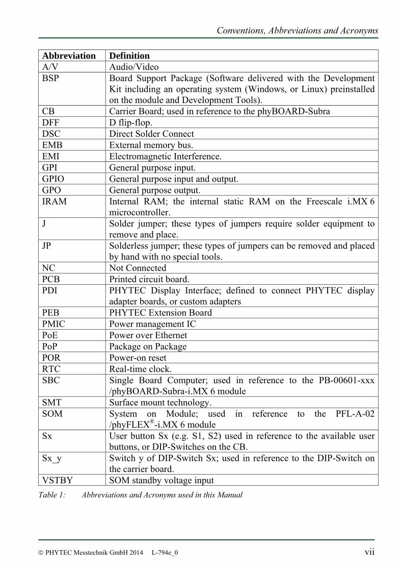
Abbreviations and Acronyms Many acronyms and abbreviations are used throughout this manual. Use the table below to navigate unfamiliar terms used in this document.
Conventions, Abbreviations and Acronyms
© PHYTEC Messtechnik GmbH 2014 L-794e_0 vii
Abbreviation Definition A/V Audio/Video BSP Board Support Package (Software delivered with the Development
Kit including an operating system (Windows, or Linux) preinstalled on the module and Development Tools).
CB Carrier Board; used in reference to the phyBOARD-Subra DFF D flip-flop. DSC Direct Solder Connect EMB External memory bus. EMI Electromagnetic Interference. GPI General purpose input. GPIO General purpose input and output. GPO General purpose output. IRAM Internal RAM; the internal static RAM on the Freescale i.MX 6
microcontroller. J Solder jumper; these types of jumpers require solder equipment to
remove and place. JP Solderless jumper; these types of jumpers can be removed and placed
by hand with no special tools. NC Not Connected PCB Printed circuit board. PDI PHYTEC Display Interface; defined to connect PHYTEC display
adapter boards, or custom adapters PEB PHYTEC Extension Board PMIC Power management IC PoE Power over Ethernet PoP Package on Package POR Power-on reset RTC Real-time clock. SBC Single Board Computer; used in reference to the PB-00601-xxx
/phyBOARD-Subra-i.MX 6 module SMT Surface mount technology. SOM System on Module; used in reference to the PFL-A-02
/phyFLEX®-i.MX 6 module Sx User button Sx (e.g. S1, S2) used in reference to the available user
buttons, or DIP-Switches on the CB. Sx_y Switch y of DIP-Switch Sx; used in reference to the DIP-Switch on
the carrier board. VSTBY SOM standby voltage input
Table 1: Abbreviations and Acronyms used in this Manual
phyBOARD-Subra-i.MX 6 [PB-00601-xxx]
viii © PHYTEC Messtechnik GmbH 2014 L-794e_0
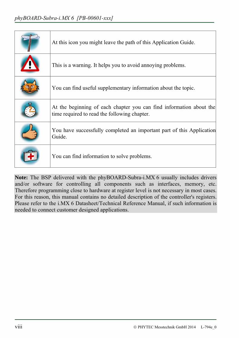
At this icon you might leave the path of this Application Guide.
This is a warning. It helps you to avoid annoying problems.
You can find useful supplementary information about the topic.
At the beginning of each chapter you can find information about the time required to read the following chapter.
You have successfully completed an important part of this Application Guide.
You can find information to solve problems.
Note: The BSP delivered with the phyBOARD-Subra-i.MX 6 usually includes drivers and/or software for controlling all components such as interfaces, memory, etc. Therefore programming close to hardware at register level is not necessary in most cases. For this reason, this manual contains no detailed description of the controller's registers. Please refer to the i.MX 6 Datasheet/Technical Reference Manual, if such information is needed to connect customer designed applications.

Preface
© PHYTEC Messtechnik GmbH 2014 L-794e_0 ix
Preface
As a member of PHYTEC's new phyBOARD® product family the phyBOARD-Subra-i.MX 6 is one of a series of PHYTEC System on Modules (SBCs) that offers various functions and configurations. PHYTEC supports a variety of 8-/16- and 32-bit controllers in two ways: (1) as the basis for Rapid Development Kits which serve as a reference and evaluation
platform (2) as insert-ready, fully functional phyBOARD® OEM modules, which can be
embedded directly into the user’s peripheral hardware design. Implementation of an OEM-able SBC subassembly as the "core" of your embedded design allows you to focus on hardware peripherals and firmware without expending resources to "re-invent" microcontroller circuitry. Furthermore, much of the value of the phyBOARD® SBC lies in its layout and test. PHYTEC's new phyBOARD® product family consists of a series of extremely compact embedded control engines featuring various processing performance classes. Production-ready Board Support Packages (BSPs) and Design Services for our hardware will further reduce your development time and risk and allow you to focus on your product expertise. Take advantage of PHYTEC products to shorten time-to-market, reduce development costs, and avoid substantial design issues and risks. With this new innovative full system solution you will be able to bring your new ideas to market in the most timely and cost-efficient manner. For more information go to: http://www.phytec.de/de/leistungen/entwicklungsunterstuetzung.html or www.phytec.eu/europe/oem-integration/evaluation-start-up.html

phyBOARD-Subra-i.MX 6 [PB-00601-xxx]
x © PHYTEC Messtechnik GmbH 2014 L-794e_0
Ordering Information
Ordering numbers: phyBOARD-Subra-i.MX 6 Development Kit: KPB-00601-xxx phyBOARD-Subra-i.MX 6 SBC: PB-00601-xxx In order to receive product specific information on changes and updates in the best way also in the future, we recommend to register at http://www.phytec.de/de/support/registrierung.html or http://www.phytec.eu/europe/support/registration.html For technical support and additional information concerning your product, please visit the support section of our web site which provides product specific information, such as errata sheets, application notes, FAQs, etc. http://www.phytec.de/de/support/faq/faq-phyBOARD-Subra-i.MX6.html or http://www.phytec.eu/europe/support/faq/ faq-phyBOARD-Subra-i.MX6.html
Declaration of Electro Magnetic Conformity of the PHYTEC phyBOARD-Subra-i.MX 6 PHYTEC Single Board Computers (henceforth products) are designed for installation in electrical appliances or as dedicated Evaluation Boards (i.e.: for use as a test and prototype platform for hardware/software development) in laboratory environments.
Caution: PHYTEC products lacking protective enclosures are subject to damage by ESD and, hence, may only be unpacked, handled or operated in environments in which sufficient precautionary measures have been taken in respect to ESD-dangers. It is also necessary that only appropriately trained personnel (such as electricians, technicians and engineers) handle and/or operate these products. Moreover, PHYTEC products should not be operated without protection circuitry if connections to the product's pin header rows are longer than 3 m. PHYTEC products fulfill the norms of the European Union’s Directive for Electro Magnetic Conformity only in accordance to the descriptions and rules of usage indicated in this hardware manual (particularly in respect to the pin header row connectors, power connector and serial interface to a host-PC). Implementation of PHYTEC products into target devices, as well as user modifications and extensions of PHYTEC products, is subject to renewed establishment of conformity to, and certification of, Electro Magnetic Directives. Users should ensure conformance following any modifications to the products as well as implementation of the products into target systems.

Preface
© PHYTEC Messtechnik GmbH 2014 L-794e_0 xi
Product Change Management and information in this manual on parts populated on the SOM / SBC
When buying a PHYTEC SOM / SBC, you will, in addition to our HW and SW offerings, receive a free obsolescence maintenance service for the HW we provide.
Our PCM (Product Change Management) Team of developers, is continuously processing, all incoming PCN's (Product Change Notifications) from vendors and distributors concerning parts which are being used in our products.
Possible impacts to the functionality of our products, due to changes of functionality or obsolesce of a certain part, are being evaluated in order to take the right masseurs in purchasing or within our HW/SW design.
Our general philosophy here is: We never discontinue a product as long as there is demand for it.
Therefore we have established a set of methods to fulfill our philosophy:
Avoiding strategies
• Avoid changes by evaluating long-livety of parts during design in phase. • Ensure availability of equivalent second source parts. • Stay in close contact with part vendors to be aware of roadmap strategies. Change management in case of functional changes
• Avoid impacts on product functionality by choosing equivalent replacement parts. • Avoid impacts on product functionality by compensating changes through HW
redesign or backward compatible SW maintenance. • Provide early change notifications concerning functional relevant changes of our
products. Change management in rare event of an obsolete and non replaceable part
• Ensure long term availability by stocking parts through last time buy management according to product forecasts.
• Offer long term frame contract to customers.
Therefore we refrain from providing detailed part specific information within this manual, which can be subject to continuous changes, due to part maintenance for our products.
In order to receive reliable, up to date and detailed information concerning parts used for our product, please contact our support team through the contact information given within this manual.

phyBOARD-Subra-i.MX 6 [PB-00601-xxx]
xii © PHYTEC Messtechnik GmbH 2014 L-794e_0
Introduction
© PHYTEC Messtechnik GmbH 2014 L-794e_0 1
1 Introduction
1.1 Hardware Overview
The phyBOARD-Subra for phyFLEX-i.MX 6 is a low-cost, feature-rich software development platform supporting the Freescale Semiconductor i.MX 6 microcontroller. Moreover, due to the numerous standard interfaces the phyBOARD-Subra-i.MX 6 can serve as bedrock for your application. At the core of the phyBOARD-Subra is the PFL-A-02 /phyFLEX®-i.MX 6 System On Module (SOM) containing the processor, DRAM, NAND Flash, power regulation, supervision, transceivers, and other core functions required to support the i.MX 6 processor. Surrounding the SOM is the PB-00601-xxx/phyBOARD-Subra carrier board, adding power input, buttons, connectors, signal breakout, and Ethernet connectivity amongst other things.
1.1.1 Features of the phyBOARD-Subra-i.MX 6
The phyBOARD-Subra-i.MX 6 supports the following features :
• PHYTEC’s phyFLEX-i.MX 6 Solo SOM
• Dimensions 150 mm x 90 mm
• Boot from NAND Flash, optional from MMC • Max. 1 GHz core clock frequency • Combicon connector for 12 V – 24 V power supply • RJ45 jack for 10/100/1000 Mbps Ethernet • Two USB Host interfaces brought out to USB2.0 Standard-A connectors • Micro-SD connector for Secure Digital / Multi Media Memory Card • CAN interface at 2×4 MicroClasp • Audiocodec with Stereo Line In, Line Out and Mic In at 2x5 MicroClasp plus mono
speaker at 2-pole Molex Spox • RS-232 transceiver supporting UART0 with data rates of up to 1 Mbps at 2x4
MicroClasp (same connector as for CAN) • Buttons for Reset and Wakeup • HDMI and display connectors • Two camera interfaces at Hirose connectors • Expansion connector for UART1, SD/MMC, SPI0 and I2C0. • Four GPIOs available at 2x4 MicroClasp (default wiring: 2x input, 2x output) • Backup battery supply for RTC with Goldcap (lasts approx. 7 days)Audiocodec with
Stereo Line In and Line Out (3×2 pin header 2.54 mm) and mono speaker (2-pole Molex)
phyBOARD-Subra-i.MX 6 [PB-00601-xxx]
2 © PHYTEC Messtechnik GmbH 2014 L-794e_0
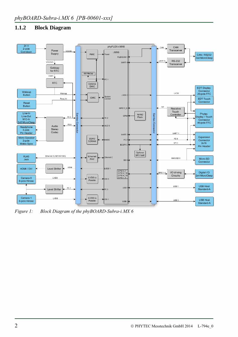
1.1.2 Block Diagram
Figure 1: Block Diagram of the phyBOARD-Subra-i.MX 6
Introduction
© PHYTEC Messtechnik GmbH 2014 L-794e_0 3
1.1.3 View of the phyBOARD-Subra-i.MX 6
Figure 2: View of the phyBOARD-Subra-i.MX 6 (top view)
Figure 3: View of the phyBOARD-Subra-i.MX 6 (bottom view)

phyBOARD-Subra-i.MX 6 [PB-00601-xxx]
4 © PHYTEC Messtechnik GmbH 2014 L-794e_0
1.2 Software Overview
1.2.1 Ubuntu
Ubuntu - which you can find on the phyBOARD-Subra-i.MX 6 Kit-DVD - is a free and open source operating system based on Debian Linux. Basically it is designed for desktop use. Web statistics suggest that Ubuntu is one of the most popular operating systems in the Linux desktop environment. The Ubuntu release which we deliver is 12.04.3 and was released on 15. February 2013. Ubuntu 12.04 code name "Precise Pangolin" is designated as a Long Term Support (LTS) release and the first stable release was on 26 April 2012. LTS means that it will be supported and updated for five years. Our Ubuntu version comes with Unity as desktop environment, dpkg as package management system, the update method is based on APT (Advanced Packaging Tool) and the user space uses GNU. 1.2.2 Eclipse
The Eclipse platform is a powerful integrated development environment (IDE). Eclipse is only a framework for developer tools instead it uses external plug-ins. The pre-installed Eclipse version on our Ubuntu LiveDVD supports C/C++ and Qt directly. This Application Guide shows you how to make use of the CDT, a set of plug-ins for C/C++ development in conjunction with the GCC C/C++ tool chain. The CDT (C/C++ Development Tooling) is an open source project (licensed under the Common Public License) implemented purely in Java as a set of plug-ins for the Eclipse SDK platform. These plug-ins add a C/C++ perspective to the Eclipse Workbench that can now support C/C++ development with a number of views and wizards, along with advanced editing and debugging support. Due to its complexity, the CDT is broken down into several components, which take the form of separate plug-ins. Each component operates as an autonomous project, with its own set of committers, bug categories, and mailing lists. However, all plug-ins are required for the CDT to work properly. Here is a list of the plug-ins/components:
• Primary CDT plug-in is the “framework” for the CDT plug-ins.
• CDT Feature Eclipse is the CDT Feature Component.
• CDT Core provides Core Model, CDOM, and Core Components.
• CDT UI is the Core UI, views, editors, and wizards.
• CDT Launch provides the launch mechanism for external tools such as the compiler and debugger.
Introduction
© PHYTEC Messtechnik GmbH 2014 L-794e_0 5
• CDT Debug Core provides debugging functions.
• CDT Debug UI provides the user interface for the CDT debugging editors, views, and wizards.
• CDT Debug MI is the application connector for MI-compatible debuggers.
1.2.3 The GNU Cross Development Tool Chain
Cross development in general refers to the overall software development process that produces a single application or a complete system running on a platform that is different from the development platform. This is an important concept when the target system doesn’t have a native set of compilation tools, or when the host system is faster and has greater resources. The platform where the actual development takes place is called the host platform. The platform where the final application is tested and run is called the target platform. In this Quick Start we are using an x86-based Linux as the host platform. As the target platform we are using the ARM®Cortex™-A8 architecture on the phyBOARD-Subra-i.MX 6 SBC. Building a program for a CPU architecture different from the one used on the machine where the compilation is done is accomplished using a cross compiler tool chain and cross-compiled libraries. In this Application Guide we are using the GNU C/C++ cross development tool chain.
phyBOARD-Subra-i.MX 6 [PB-00601-xxx]
6 © PHYTEC Messtechnik GmbH 2014 L-794e_0
2 Application Programming
During this chapter you will learn how to build your own C/C++ and Qt applications for the target with the help of Eclipse. We establish that you have first played through our Quickstart Guide.
As all changes on the example projects will be lost if you proceed using the live environment we recommend to install our modified Ubuntu LiveDVD. If you only want to make your own fast experience with our phyBOARD-Subra-i.MX 6-Kit you can go on with section 2.2 “Working with Eclipse”.
To ensure successful introduction to the development with the phyBOARD-Subra-i.MX 6 we strongly recommend continuing with the modified Ubuntu, either in a live environment, or completely installed on your PC as described in the next section. Nontheless; if you want to use your already existing environment we explain how to modify your system to get the same experience like our LiveDVD in the System Guide in section “Setup your own host PC”.
2.1 Installing our modified Ubuntu LiveDVD
As described above, this step is not needed to successfully finish this chapter but for more in-depth development it is better to install our LiveDVD on your computer or into a virtual machine. If another operating system is installed on your computer, you should first make a backup of your important files. Before we can start, make sure that your computer is set to boot from DVD before it boots from a hard disk drive. Insert the Linux-phyBOARD-Subra-i.MX 6-Kit-DVD into your DVD drive. Start or restart your computer. Your system finds a bootable DVD and starts from it.
After a while a language screen appears.
Application Programming
© PHYTEC Messtechnik GmbH 2014 L-794e_0 7
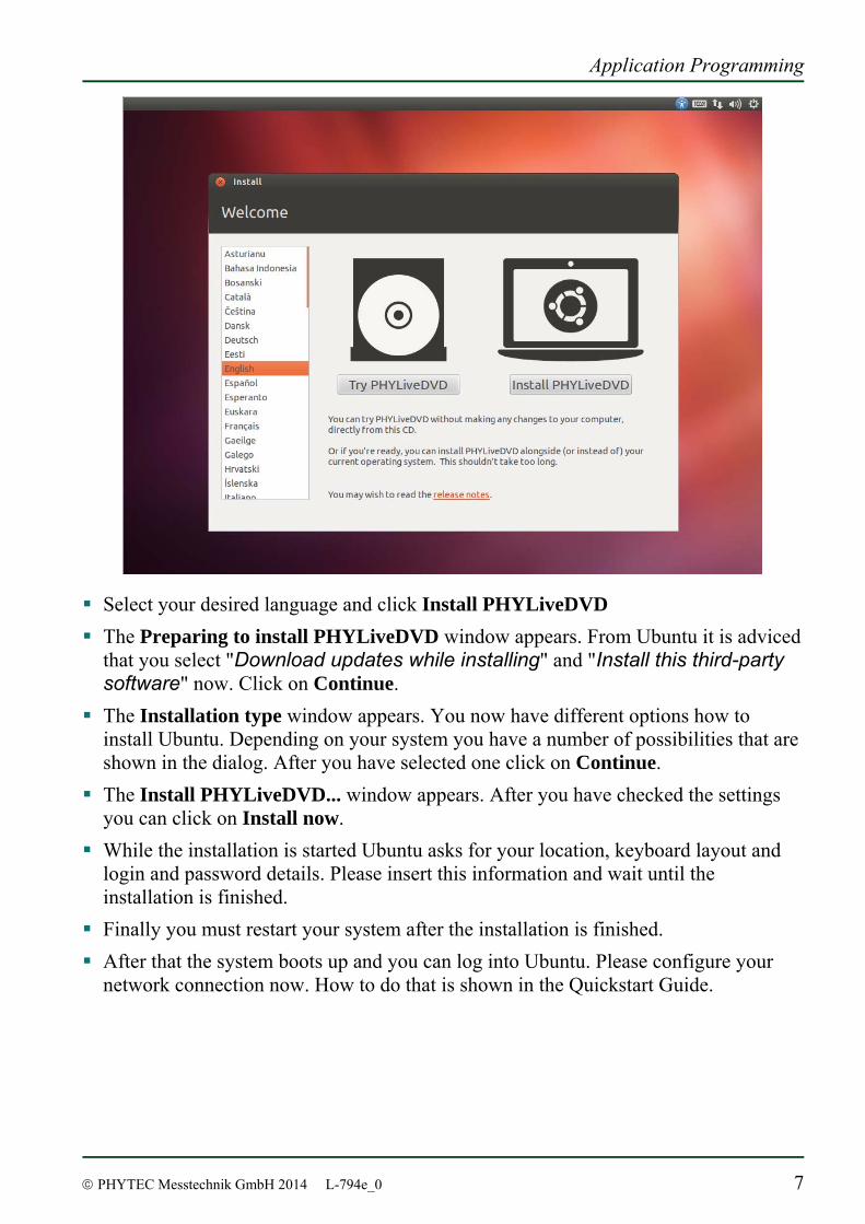
Select your desired language and click Install PHYLiveDVD The Preparing to install PHYLiveDVD window appears. From Ubuntu it is adviced
that you select "Download updates while installing" and "Install this third-party software" now. Click on Continue.
The Installation type window appears. You now have different options how to install Ubuntu. Depending on your system you have a number of possibilities that are shown in the dialog. After you have selected one click on Continue.
The Install PHYLiveDVD... window appears. After you have checked the settings you can click on Install now.
While the installation is started Ubuntu asks for your location, keyboard layout and login and password details. Please insert this information and wait until the installation is finished.
Finally you must restart your system after the installation is finished. After that the system boots up and you can log into Ubuntu. Please configure your
network connection now. How to do that is shown in the Quickstart Guide.
phyBOARD-Subra-i.MX 6 [PB-00601-xxx]
8 © PHYTEC Messtechnik GmbH 2014 L-794e_0
2.2 Working with Eclipse
Now we start developing our own applications with the help of Eclipse. First we take a look on the C programming language before we go on with programming a QT project. At the end of this chapter we explain how to execute your written programs automatically when booting the target. 2.2.1 Programming in the C/C++ perspective
We are starting with the C/C++ workbench. Therefore you will import an existing Eclipse project into your workspace. The imported example project will be compiled with the cross compiler. After compiling the project, you will copy and execute the newly created program on the target. 2.2.1.1 Work with the demo project
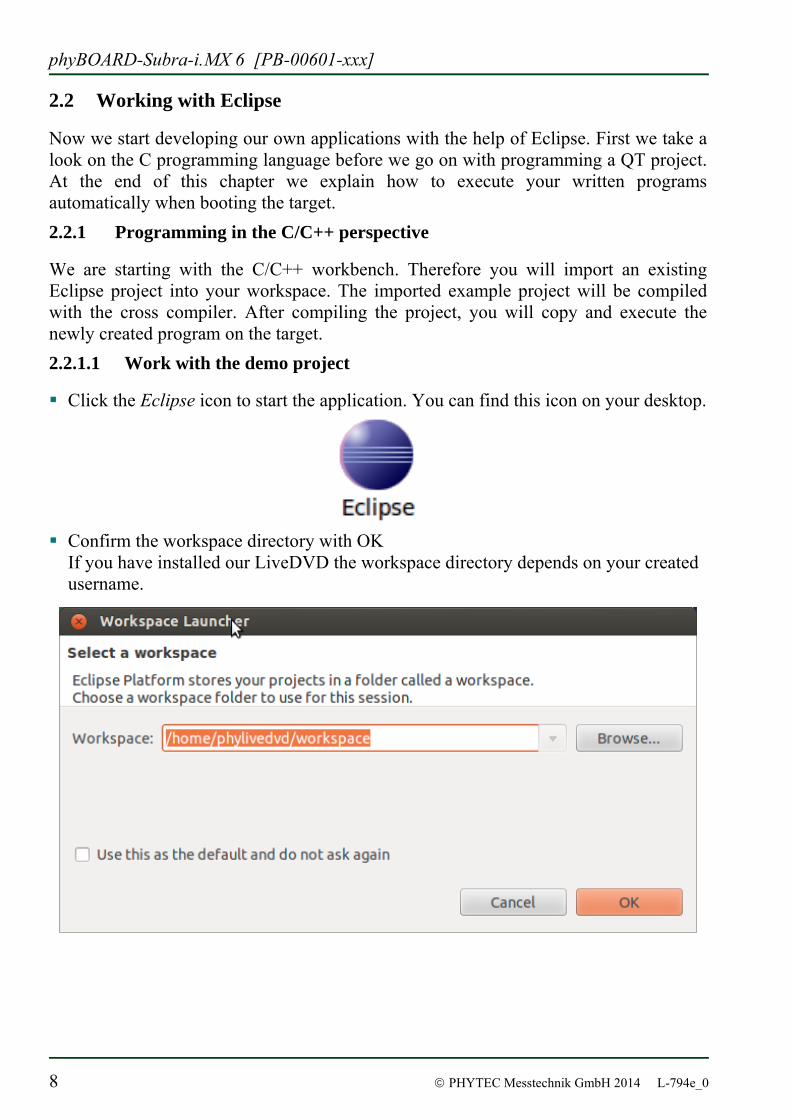
Click the Eclipse icon to start the application. You can find this icon on your desktop.
Confirm the workspace directory with OK If you have installed our LiveDVD the workspace directory depends on your created username.
Application Programming
© PHYTEC Messtechnik GmbH 2014 L-794e_0 9
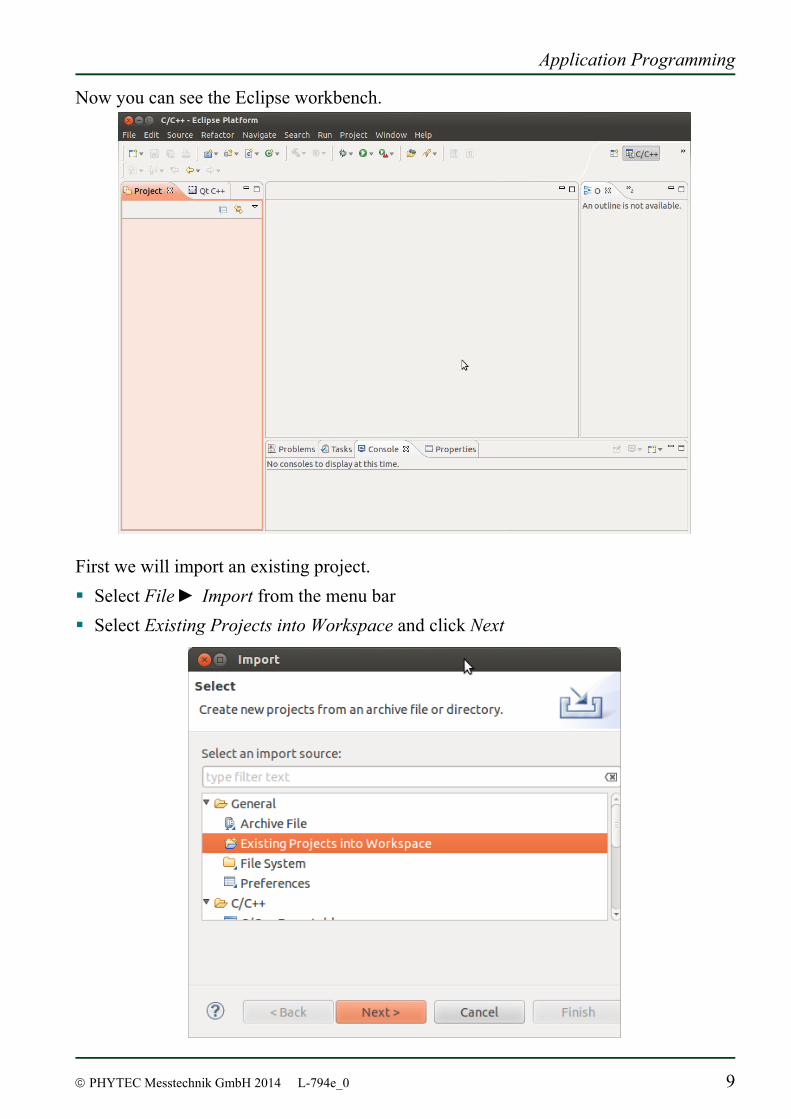
Now you can see the Eclipse workbench.
First we will import an existing project. Select File ► Import from the menu bar Select Existing Projects into Workspace and click Next
phyBOARD-Subra-i.MX 6 [PB-00601-xxx]
10 © PHYTEC Messtechnik GmbH 2014 L-794e_0
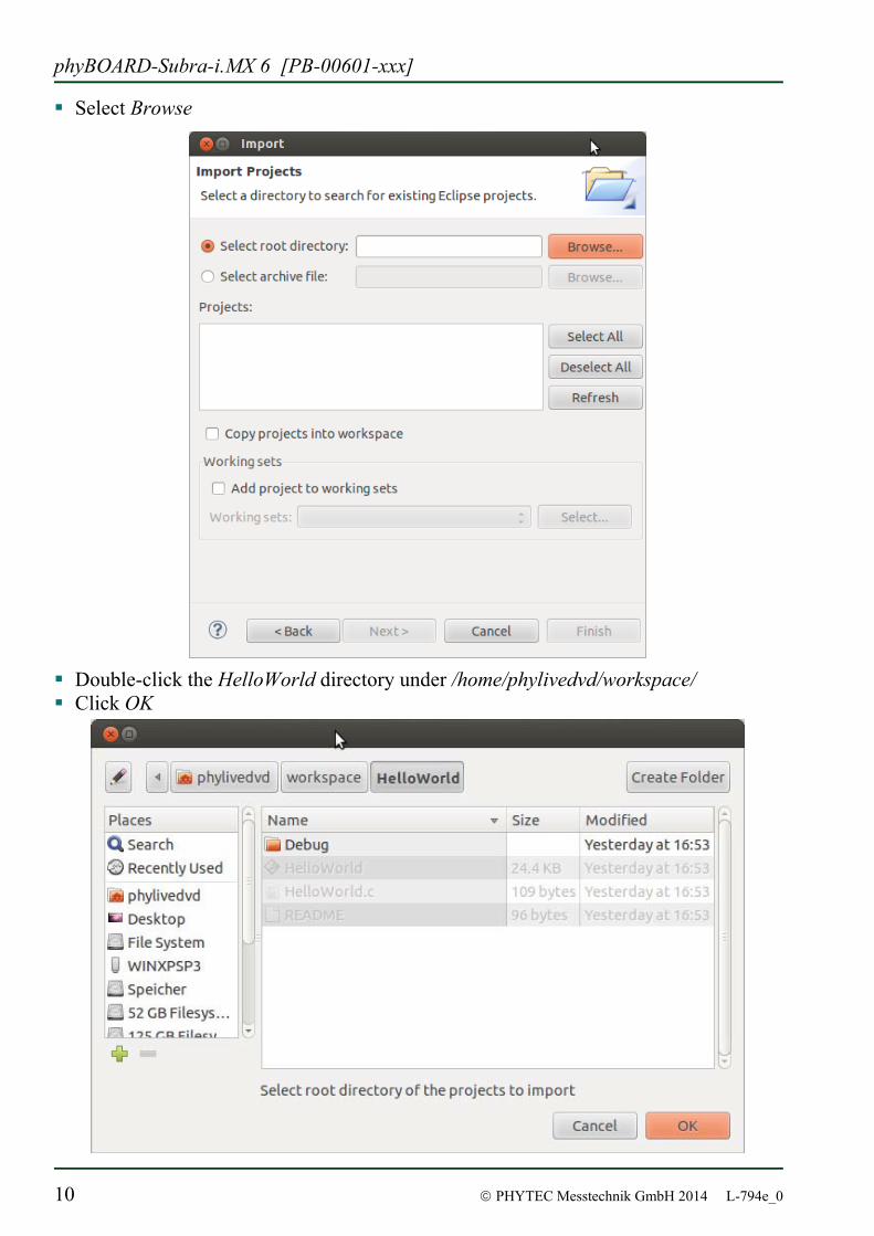
Select Browse
Double-click the HelloWorld directory under /home/phylivedvd/workspace/ Click OK
Application Programming
© PHYTEC Messtechnik GmbH 2014 L-794e_0 11
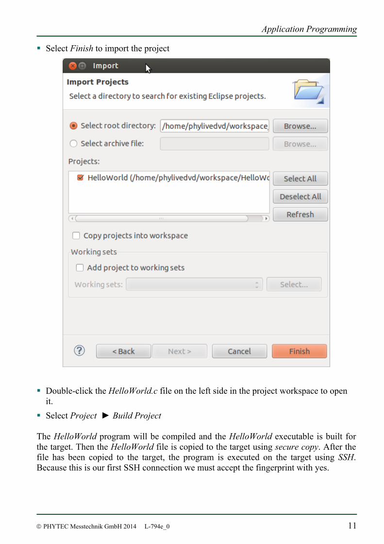
Select Finish to import the project
Double-click the HelloWorld.c file on the left side in the project workspace to open
it. Select Project ► Build Project
The HelloWorld program will be compiled and the HelloWorld executable is built for the target. Then the HelloWorld file is copied to the target using secure copy. After the file has been copied to the target, the program is executed on the target using SSH. Because this is our first SSH connection we must accept the fingerprint with yes.
phyBOARD-Subra-i.MX 6 [PB-00601-xxx]
12 © PHYTEC Messtechnik GmbH 2014 L-794e_0
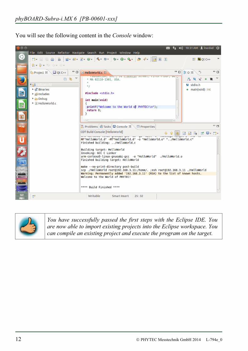
You will see the following content in the Console window:
You have successfully passed the first steps with the Eclipse IDE. You are now able to import existing projects into the Eclipse workspace. You can compile an existing project and execute the program on the target.
Application Programming
© PHYTEC Messtechnik GmbH 2014 L-794e_0 13
2.2.1.2 Creating a New Project
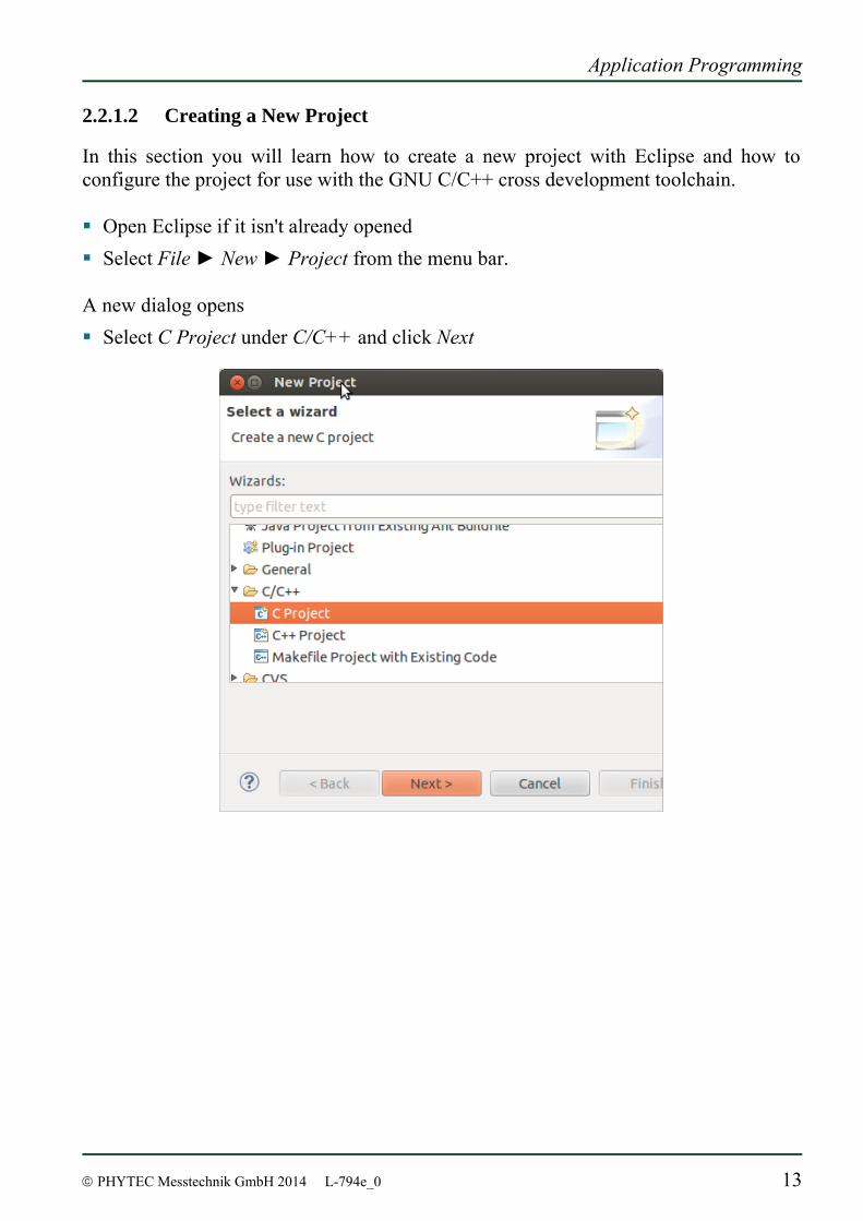
In this section you will learn how to create a new project with Eclipse and how to configure the project for use with the GNU C/C++ cross development toolchain. Open Eclipse if it isn't already opened Select File ► New ► Project from the menu bar.
A new dialog opens Select C Project under C/C++ and click Next
phyBOARD-Subra-i.MX 6 [PB-00601-xxx]
14 © PHYTEC Messtechnik GmbH 2014 L-794e_0
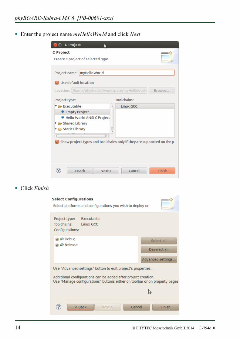
Enter the project name myHelloWorld and click Next
Click Finish
Application Programming
© PHYTEC Messtechnik GmbH 2014 L-794e_0 15
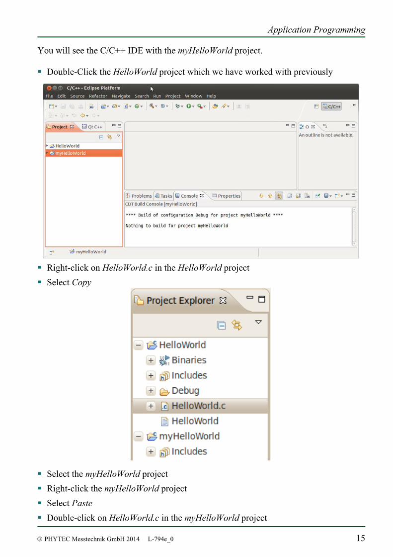
You will see the C/C++ IDE with the myHelloWorld project. Double-Click the HelloWorld project which we have worked with previously
Right-click on HelloWorld.c in the HelloWorld project Select Copy
Select the myHelloWorld project Right-click the myHelloWorld project Select Paste Double-click on HelloWorld.c in the myHelloWorld project
phyBOARD-Subra-i.MX 6 [PB-00601-xxx]
16 © PHYTEC Messtechnik GmbH 2014 L-794e_0
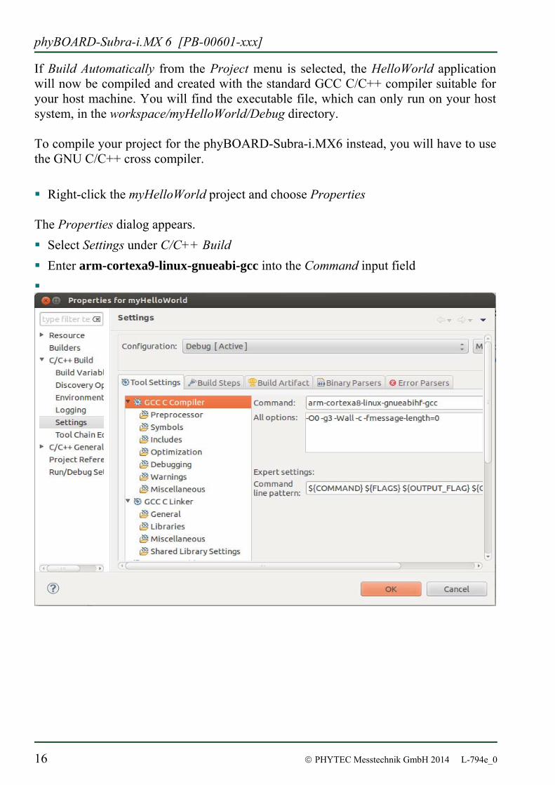
If Build Automatically from the Project menu is selected, the HelloWorld application will now be compiled and created with the standard GCC C/C++ compiler suitable for your host machine. You will find the executable file, which can only run on your host system, in the workspace/myHelloWorld/Debug directory. To compile your project for the phyBOARD-Subra-i.MX6 instead, you will have to use the GNU C/C++ cross compiler. Right-click the myHelloWorld project and choose Properties
The Properties dialog appears. Select Settings under C/C++ Build Enter arm-cortexa9-linux-gnueabi-gcc into the Command input field
Application Programming
© PHYTEC Messtechnik GmbH 2014 L-794e_0 17
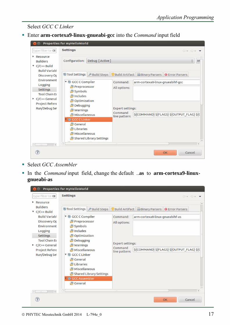
Select GCC C Linker Enter arm-cortexa9-linux-gnueabi-gcc into the Command input field
Select GCC Assembler In the Command input field, change the default ..as to arm-cortexa9-linux-
gnueabi-as
phyBOARD-Subra-i.MX 6 [PB-00601-xxx]
18 © PHYTEC Messtechnik GmbH 2014 L-794e_0
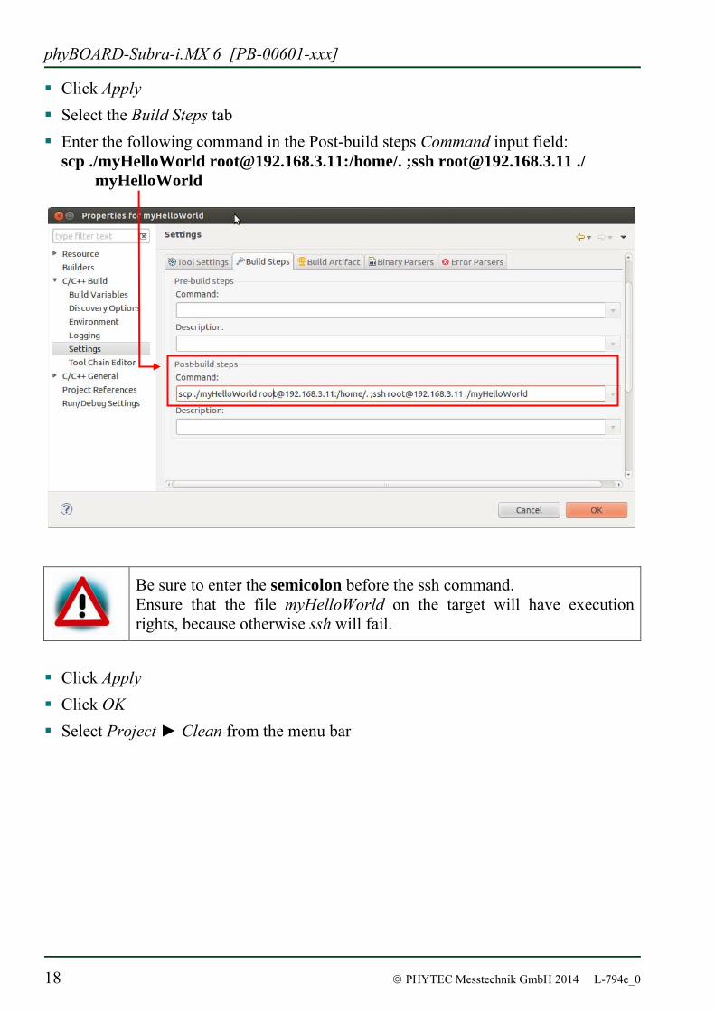
Click Apply Select the Build Steps tab Enter the following command in the Post-build steps Command input field:
scp ./myHelloWorld [email protected]:/home/. ;ssh [email protected] ./ myHelloWorld
Be sure to enter the semicolon before the ssh command. Ensure that the file myHelloWorld on the target will have execution rights, because otherwise ssh will fail.
Click Apply Click OK Select Project ► Clean from the menu bar
Application Programming
© PHYTEC Messtechnik GmbH 2014 L-794e_0 19
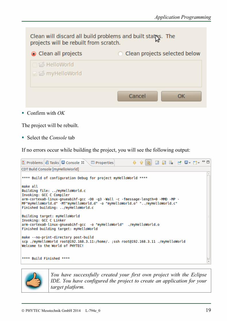
Confirm with OK The project will be rebuilt. Select the Console tab
If no errors occur while building the project, you will see the following output:
You have successfully created your first own project with the Eclipse IDE. You have configured the project to create an application for your target platform.
phyBOARD-Subra-i.MX 6 [PB-00601-xxx]
20 © PHYTEC Messtechnik GmbH 2014 L-794e_0
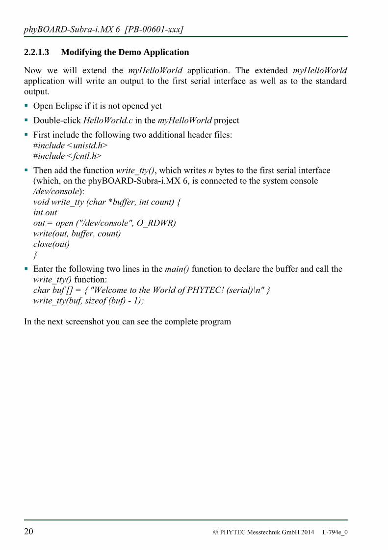
2.2.1.3 Modifying the Demo Application
Now we will extend the myHelloWorld application. The extended myHelloWorld application will write an output to the first serial interface as well as to the standard output. Open Eclipse if it is not opened yet Double-click HelloWorld.c in the myHelloWorld project First include the following two additional header files:
#include <unistd.h> #include <fcntl.h>
Then add the function write_tty(), which writes n bytes to the first serial interface (which, on the phyBOARD-Subra-i.MX 6, is connected to the system console /dev/console): void write_tty (char *buffer, int count) { int out out = open ("/dev/console", O_RDWR) write(out, buffer, count) close(out) }
Enter the following two lines in the main() function to declare the buffer and call the write_tty() function: char buf [] = { "Welcome to the World of PHYTEC! (serial)\n" } write_tty(buf, sizeof (buf) - 1);
In the next screenshot you can see the complete program
Application Programming
© PHYTEC Messtechnik GmbH 2014 L-794e_0 21
Save your program after changing the code
The application will be compiled, built, copied to the target and executed. Click the Microcom icon on the desktop
phyBOARD-Subra-i.MX 6 [PB-00601-xxx]
22 © PHYTEC Messtechnik GmbH 2014 L-794e_0
If you are not logged in, enter root and press Enter Type ./myHelloWorld to start the application You will see the following output:
Welcome to the World of PHYTEC! (serial) Welcome to the World of PHYTEC!
Close Microcom When you start the application via an SSH session, you only see one output line. When you execute the program with Microcom, you see both output lines.
The first line is a direct output on the serial interface. You can not see this line in a SSH session, because you are connected over a TCP/IP connection to the target. With Microcom, however, you have direct access to the serial interface, so you can also see the line that is written to the serial console.
In this section you have changed an existing application. You also learned how to access the serial interface. First you called the function open() on the device /dev/console. The return value of this function was a file descriptor. With the file descriptor you called the function write() to send n bytes to the device /dev/console. After that, the file descriptor was closed with the function close().
This procedure is in principle quite typical for Linux, because Linux treats everything like a file.
Application Programming
© PHYTEC Messtechnik GmbH 2014 L-794e_0 23
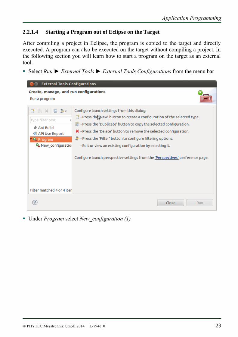
2.2.1.4 Starting a Program out of Eclipse on the Target
After compiling a project in Eclipse, the program is copied to the target and directly executed. A program can also be executed on the target without compiling a project. In the following section you will learn how to start a program on the target as an external tool. Select Run ► External Tools ► External Tools Configurations from the menu bar
Under Program select New_configuration (1)
phyBOARD-Subra-i.MX 6 [PB-00601-xxx]
24 © PHYTEC Messtechnik GmbH 2014 L-794e_0
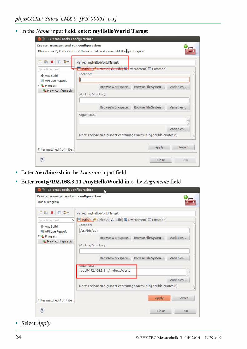
In the Name input field, enter: myHelloWorld Target
Enter /usr/bin/ssh in the Location input field Enter [email protected] ./myHelloWorld into the Arguments field
Select Apply
Application Programming
© PHYTEC Messtechnik GmbH 2014 L-794e_0 25
Select Run If you want to execute the program the next time, you can use the Run External Programs button from the menu bar.
You have successfully created your own Eclipse project and you learned how to execute a program on the target.
2.2.2 Debugging an Example Project
In this chapter you will learn using the GNU debugger GDB on the host for remote debugging in conjunction with the GDB server on the target. GDB is the symbolic debugger of the GNU project and is arguably the most important debugging tool for any Linux system. First you will start the GDB server on the target. Then you will configure the Eclipse platform and start the GNU debugger out of Eclipse using the Debug view. The CDT extends the standard Eclipse Debug view with functions for debugging C/C++ code. The Debug view allows you to manage the debugging and running of a program in the workbench. Using the Debug view you will be able to set breakpoints/watchpoints in the code and trace variables and registers. The Debug view displays the stack frame for the threads of each target you are debugging. Each thread in your program appears as a node in the tree, and the Debug view displays the process for each target you are running. The GDB client is running on the host and is used to control the GDB server on the target, which in turn controls the application running on the target. GDB client and GDB server can communicate over a TCP/IP network connection as well as via a serial interface. In this Application Guide we will only describe debugging via TCP/IP.
phyBOARD-Subra-i.MX 6 [PB-00601-xxx]
26 © PHYTEC Messtechnik GmbH 2014 L-794e_0
2.2.2.1 Starting the GDB server on the target
In this passage you will learn how to start the GDB server on the target. The GDB server will be used to start and control the myHelloWorld program. To debug a program with GDB, the program needs extended debugging symbols. These have been already added while building the program.
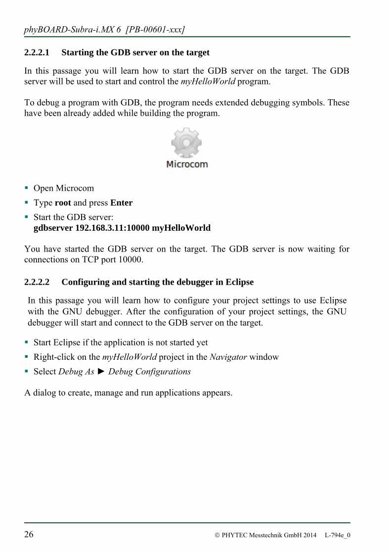
Open Microcom Type root and press Enter Start the GDB server:
gdbserver 192.168.3.11:10000 myHelloWorld
You have started the GDB server on the target. The GDB server is now waiting for connections on TCP port 10000.
2.2.2.2 Configuring and starting the debugger in Eclipse
In this passage you will learn how to configure your project settings to use Eclipse with the GNU debugger. After the configuration of your project settings, the GNU debugger will start and connect to the GDB server on the target.
Start Eclipse if the application is not started yet Right-click on the myHelloWorld project in the Navigator window Select Debug As ► Debug Configurations
A dialog to create, manage and run applications appears.
Application Programming
© PHYTEC Messtechnik GmbH 2014 L-794e_0 27
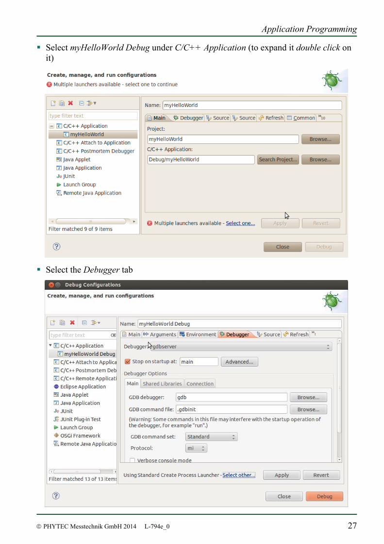
Select myHelloWorld Debug under C/C++ Application (to expand it double click on it)
Select the Debugger tab
phyBOARD-Subra-i.MX 6 [PB-00601-xxx]
28 © PHYTEC Messtechnik GmbH 2014 L-794e_0
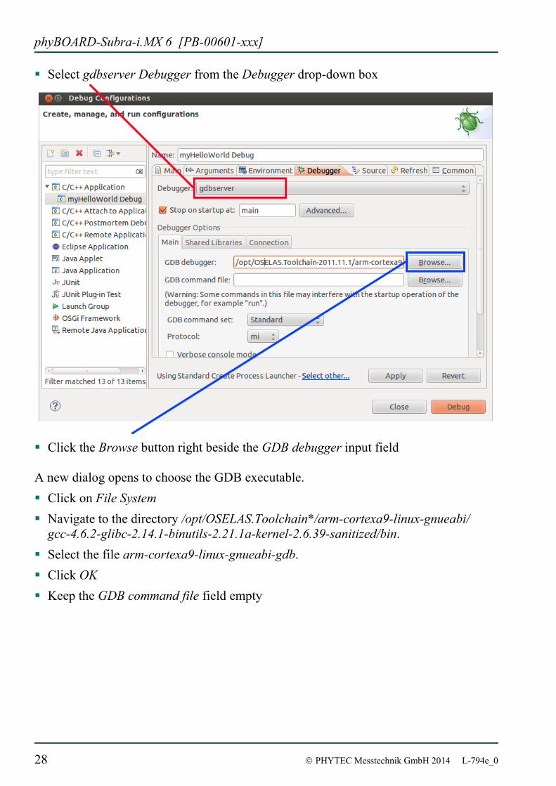
Select gdbserver Debugger from the Debugger drop-down box
Click the Browse button right beside the GDB debugger input field A new dialog opens to choose the GDB executable. Click on File System Navigate to the directory /opt/OSELAS.Toolchain*/arm-cortexa9-linux-gnueabi/
gcc-4.6.2-glibc-2.14.1-binutils-2.21.1a-kernel-2.6.39-sanitized/bin. Select the file arm-cortexa9-linux-gnueabi-gdb. Click OK Keep the GDB command file field empty
Application Programming
© PHYTEC Messtechnik GmbH 2014 L-794e_0 29
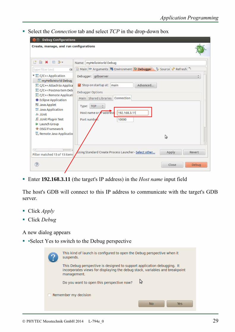
Select the Connection tab and select TCP in the drop-down box
Enter 192.168.3.11 (the target's IP address) in the Host name input field The host's GDB will connect to this IP address to communicate with the target's GDB server. Click Apply Click Debug
A new dialog appears •Select Yes to switch to the Debug perspective
phyBOARD-Subra-i.MX 6 [PB-00601-xxx]
30 © PHYTEC Messtechnik GmbH 2014 L-794e_0
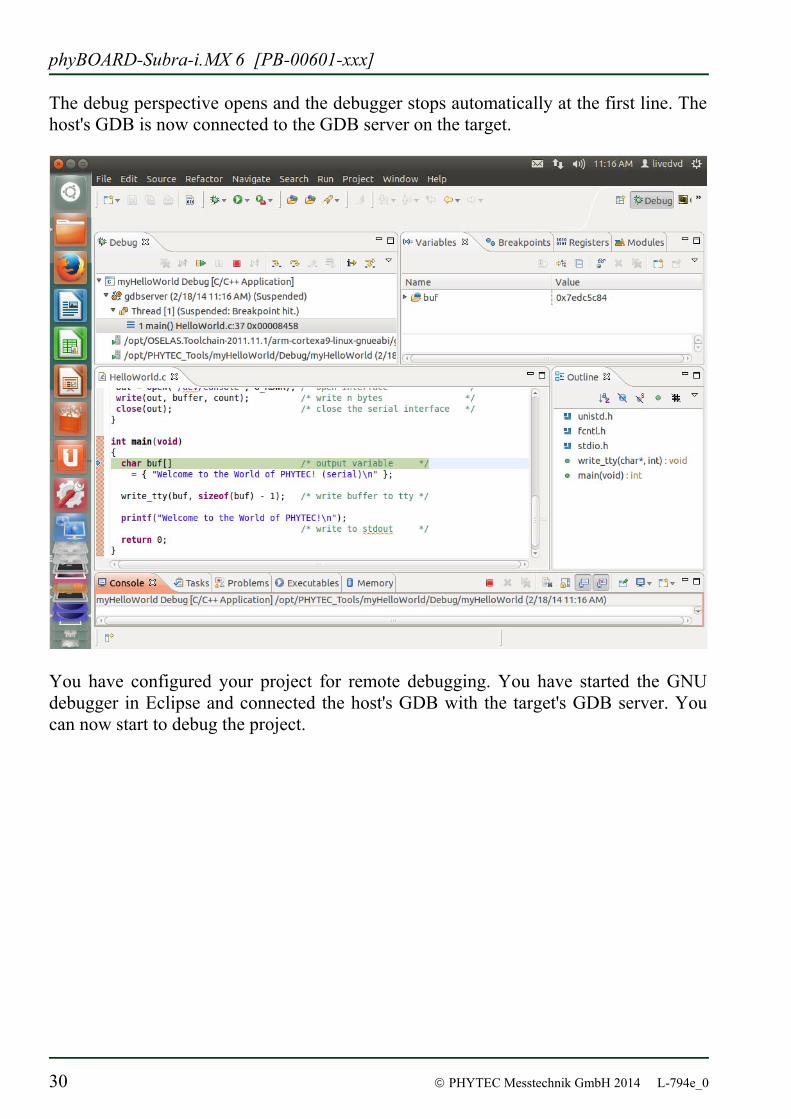
The debug perspective opens and the debugger stops automatically at the first line. The host's GDB is now connected to the GDB server on the target.
You have configured your project for remote debugging. You have started the GNU debugger in Eclipse and connected the host's GDB with the target's GDB server. You can now start to debug the project.
Application Programming
© PHYTEC Messtechnik GmbH 2014 L-794e_0 31
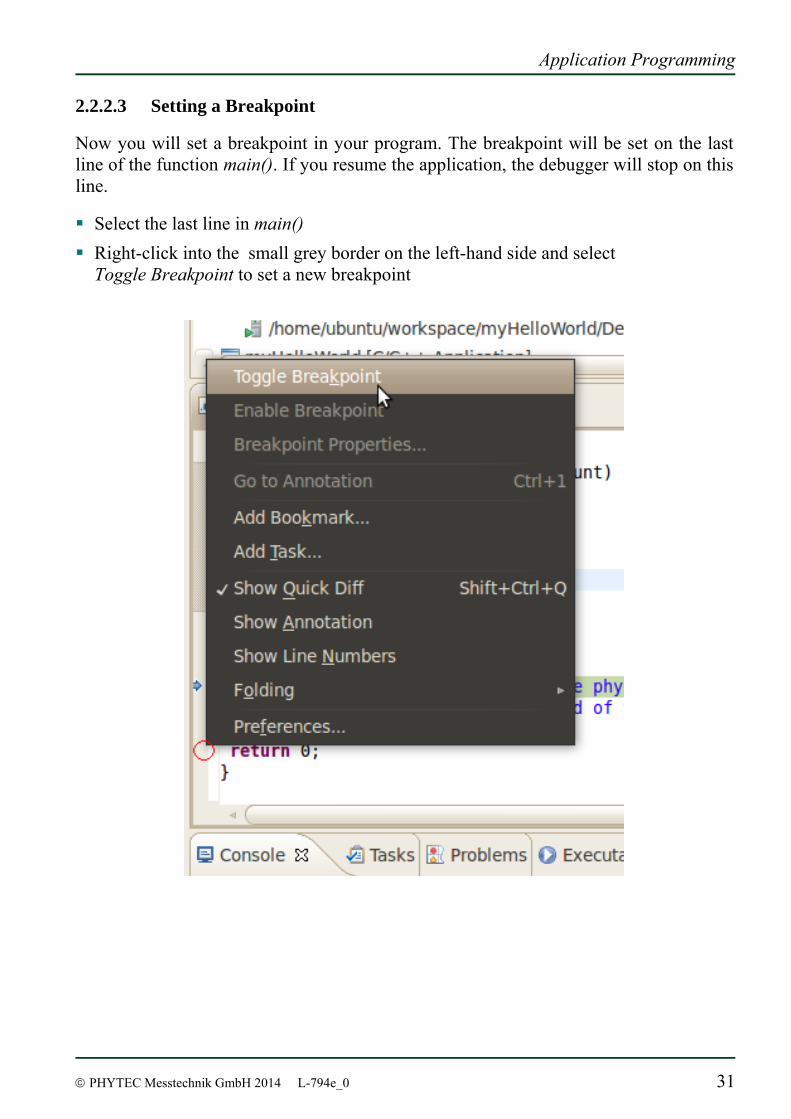
2.2.2.3 Setting a Breakpoint
Now you will set a breakpoint in your program. The breakpoint will be set on the last line of the function main(). If you resume the application, the debugger will stop on this line. Select the last line in main() Right-click into the small grey border on the left-hand side and select
Toggle Breakpoint to set a new breakpoint
phyBOARD-Subra-i.MX 6 [PB-00601-xxx]
32 © PHYTEC Messtechnik GmbH 2014 L-794e_0
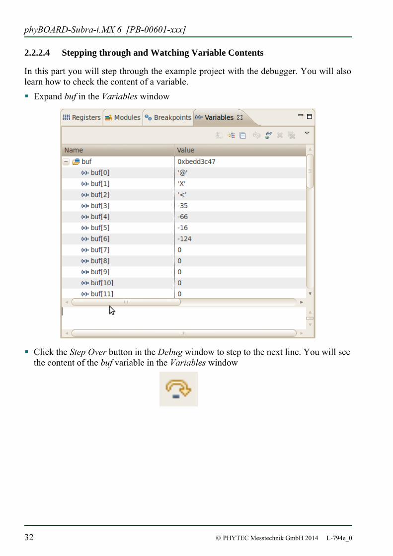
2.2.2.4 Stepping through and Watching Variable Contents
In this part you will step through the example project with the debugger. You will also learn how to check the content of a variable. Expand buf in the Variables window
Click the Step Over button in the Debug window to step to the next line. You will see the content of the buf variable in the Variables window
Application Programming
© PHYTEC Messtechnik GmbH 2014 L-794e_0 33
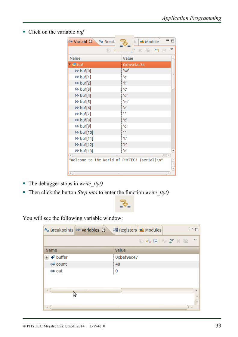
Click on the variable buf
The debugger stops in write_tty() Then click the button Step into to enter the function write_tty()
You will see the following variable window:
phyBOARD-Subra-i.MX 6 [PB-00601-xxx]
34 © PHYTEC Messtechnik GmbH 2014 L-794e_0
Click on the variable buffer You will probably see a different address on the buffer pointer. Remember what address is shown in your case; you will need this address later.
2.2.2.5 Stepping through and Changing Variable Contents
In this section you will change the value of a variable. At the end of this part you will see the effect of this change.
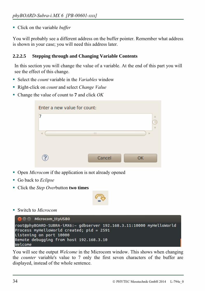
Select the count variable in the Variables window Right-click on count and select Change Value Change the value of count to 7 and click OK
Open Microcom if the application is not already opened Go back to Eclipse Click the Step Overbutton two times
Switch to Microcom
You will see the output Welcome in the Microcom window. This shows when changing the counter variable's value to 7 only the first seven characters of the buffer are displayed, instead of the whole sentence.
Application Programming
© PHYTEC Messtechnik GmbH 2014 L-794e_0 35
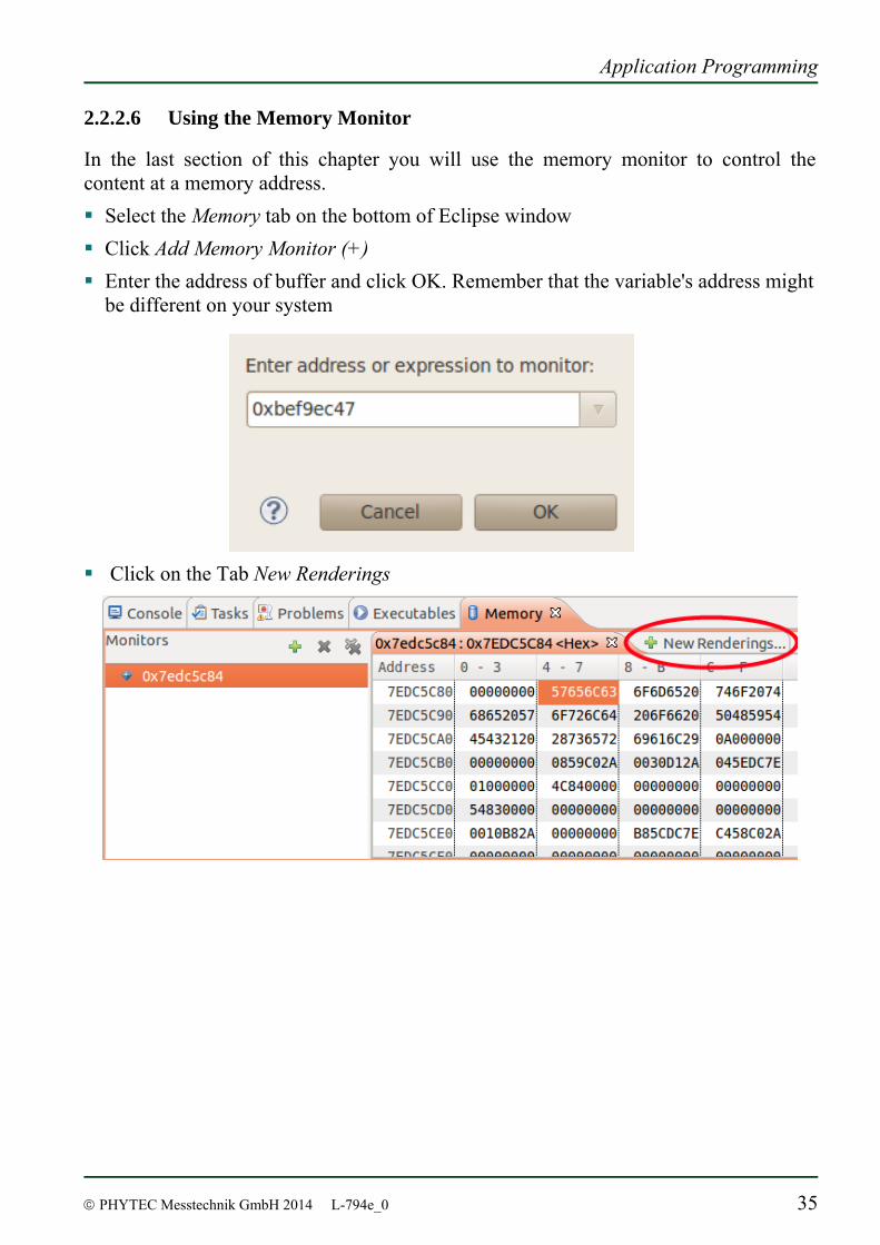
2.2.2.6 Using the Memory Monitor
In the last section of this chapter you will use the memory monitor to control the content at a memory address. Select the Memory tab on the bottom of Eclipse window Click Add Memory Monitor (+) Enter the address of buffer and click OK. Remember that the variable's address might
be different on your system
Click on the Tab New Renderings
phyBOARD-Subra-i.MX 6 [PB-00601-xxx]
36 © PHYTEC Messtechnik GmbH 2014 L-794e_0
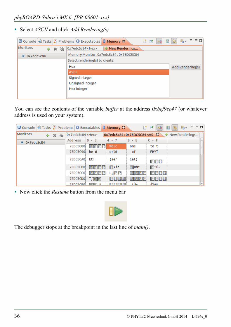
Select ASCII and click Add Rendering(s)
You can see the contents of the variable buffer at the address 0xbef9ec47 (or whatever address is used on your system).
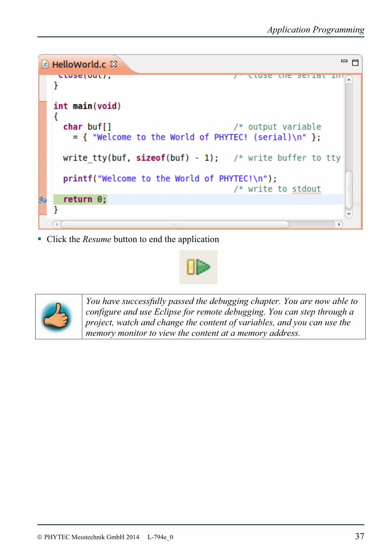
Now click the Resume button from the menu bar
The debugger stops at the breakpoint in the last line of main().
Application Programming
© PHYTEC Messtechnik GmbH 2014 L-794e_0 37
Click the Resume button to end the application
You have successfully passed the debugging chapter. You are now able to configure and use Eclipse for remote debugging. You can step through a project, watch and change the content of variables, and you can use the memory monitor to view the content at a memory address.
phyBOARD-Subra-i.MX 6 [PB-00601-xxx]
38 © PHYTEC Messtechnik GmbH 2014 L-794e_0
2.2.3 Programming in the Qt C++ perspective
In this section our attention goes to the Qt framework, which gives us tools to develop graphical user interfaces. With the help of an example project we will give you a short introduction of how to work with Qt.
2.2.3.1 Importing the demo application
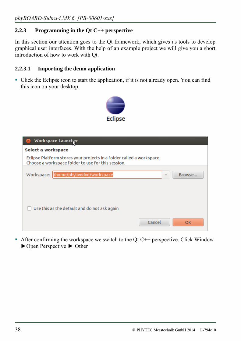
Click the Eclipse icon to start the application, if it is not already open. You can find this icon on your desktop.
After confirming the workspace we switch to the Qt C++ perspective. Click Window ►Open Perspective ► Other
Application Programming
© PHYTEC Messtechnik GmbH 2014 L-794e_0 39
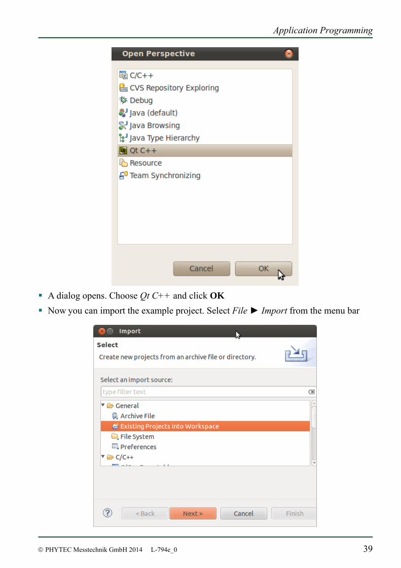
A dialog opens. Choose Qt C++ and click OK Now you can import the example project. Select File ► Import from the menu bar
phyBOARD-Subra-i.MX 6 [PB-00601-xxx]
40 © PHYTEC Messtechnik GmbH 2014 L-794e_0
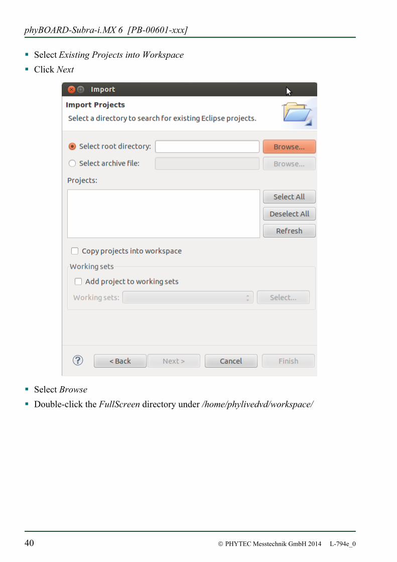
Select Existing Projects into Workspace Click Next
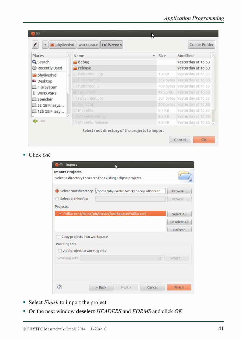
Select Browse Double-click the FullScreen directory under /home/phylivedvd/workspace/
Application Programming
© PHYTEC Messtechnik GmbH 2014 L-794e_0 41
Click OK
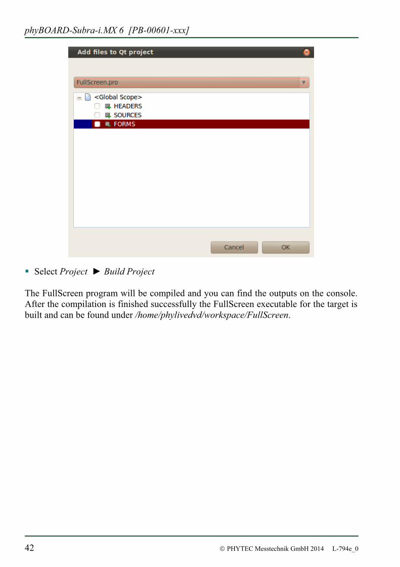
Select Finish to import the project On the next window deselect HEADERS and FORMS and click OK
phyBOARD-Subra-i.MX 6 [PB-00601-xxx]
42 © PHYTEC Messtechnik GmbH 2014 L-794e_0
Select Project ► Build Project The FullScreen program will be compiled and you can find the outputs on the console. After the compilation is finished successfully the FullScreen executable for the target is built and can be found under /home/phylivedvd/workspace/FullScreen.
Application Programming
© PHYTEC Messtechnik GmbH 2014 L-794e_0 43
2.2.3.2 Handle with the demo application
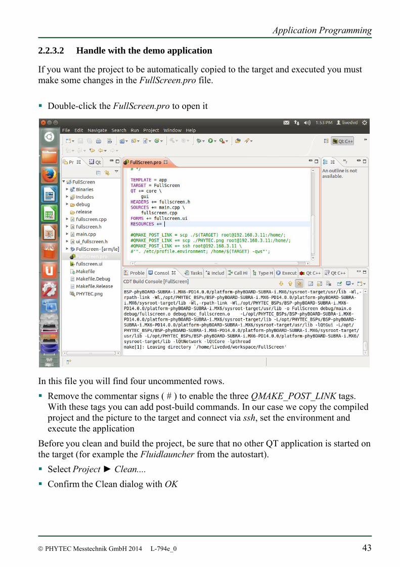
If you want the project to be automatically copied to the target and executed you must make some changes in the FullScreen.pro file. Double-click the FullScreen.pro to open it
In this file you will find four uncommented rows. Remove the commentar signs ( # ) to enable the three QMAKE_POST_LINK tags.
With these tags you can add post-build commands. In our case we copy the compiled project and the picture to the target and connect via ssh, set the environment and execute the application
Before you clean and build the project, be sure that no other QT application is started on the target (for example the Fluidlauncher from the autostart). Select Project ► Clean.... Confirm the Clean dialog with OK
phyBOARD-Subra-i.MX 6 [PB-00601-xxx]
44 © PHYTEC Messtechnik GmbH 2014 L-794e_0
After the FullScreen program is compiled the QMAKE_POST_LINK is called. The FullScreen file is copied to the target using secure copy and executed using SSH. At the connected display on the target the project is started and you can change between windowed and fullscreen mode by clicking the button. By touching/pressing the X you can close the program.
You have successfully imported and built a Qt project in Eclipse. You havve also learned to run your application on the target.
Knowing how to work with Eclipse and how to develop and execute an application on the phyBOARD-Subra-i.MX 6, you are now ready prepared to start your project. The following section will give you detailed information on the different features and interfaces of the phyBOARD-Subra and how to use them within your application. If your project is more complex, or if you crave more information about working with the BSP, continue with chapter Fehler! Verweisquelle konnte nicht gefunden werden.. Chapter Fehler! Verweisquelle konnte nicht gefunden werden.ff inlcude step by step instructions on how to modify and download the BSP using PTXdist. They also include system level information on the phyBOARD-Subra-i.MX 6.
Accessing the phyBOARD-Subra Features
© PHYTEC Messtechnik GmbH 2014 L-794e_0 45
3 Accessing the phyBOARD-Subra Features
PHYTEC phyBOARD-Subra is fully equipped with all mechanical and electrical components necessary for the speedy and secure start-up and subsequent communication to and programming of applicable PHYTEC System on Module (SOM) modules. phyBOARD-Subra Boards are designed for evaluation, testing and prototyping of PHYTEC System on Module in laboratory environments prior to their use in customer designed applications.
3.1 Concept of the phyBOARD-Subra
The phyBOARD-Subra provides a flexible development platform enabling quick and easy start-up and subsequent programming of its soldered phyFLEX-i.MX 6 System on Module. The carrier board design allows easy connection of additional extension boards featuring various functions that support fast and convenient prototyping and software evaluation. The carrier board is compatible with phyFLEX-i.MX 6 only. This modular development platform concept includes the following components: • the phyFLEX-i.MX 6 module populated by default with the i.MX 6 processor and
all applicable SOM circuitry such as DDR SDRAM, Flash, PHYs, and transceivers to name a few.
• the phyBOARD-Subra which offers all essential components and connectors for
start-up including: A power socket which enables connection to an external power adapter, interface connectors such as USB, Ethernet and microSDHC card slot allowing for use of the SOM's interfaces with standard cable.
The following sections contain specific information relevant to the operation of the phyFLEX-i.MX 6 mounted on the phyBOARD-Subra Carrier Board.
phyBOARD-Subra-i.MX 6 [PB-00601-xxx]
46 © PHYTEC Messtechnik GmbH 2014 L-794e_0
3.2 Overview of the phyBOARD-Subra Peripherals
The phyBOARD-Subra is depicted in Figure 2. It features many different interfaces and is equipped with the components as listed in Fehler! Verweisquelle konnte nicht gefunden werden., Table 3, and Table 4. For a more detailed description of each peripheral refer to the appropriate chapter listed in the applicable table. Figure 2 highlights the location of each peripheral for easy identification.
3.2.1 Connectors and Pin Header
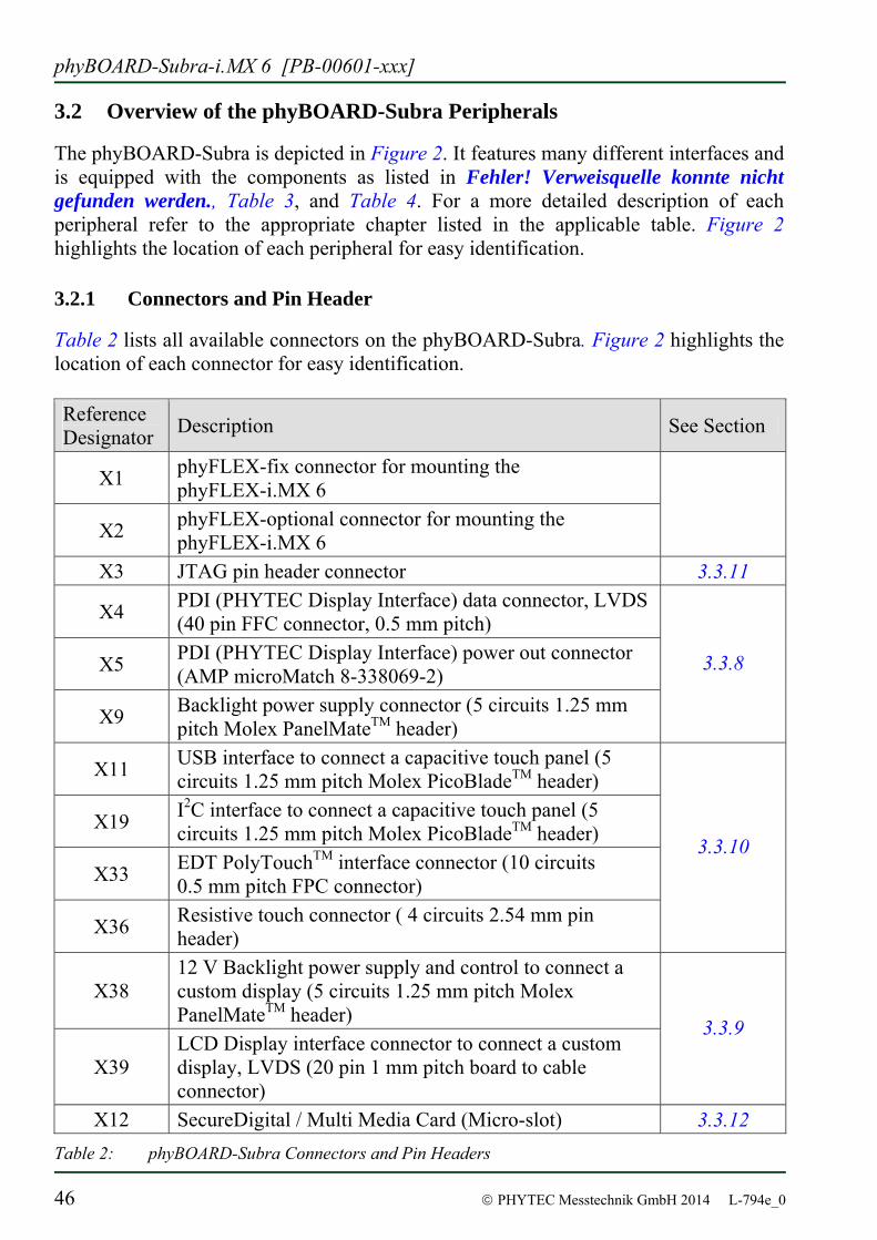
Table 2 lists all available connectors on the phyBOARD-Subra. Figure 2 highlights the location of each connector for easy identification. Reference Designator Description See Section
X1 phyFLEX-fix connector for mounting the phyFLEX-i.MX 6
X2 phyFLEX-optional connector for mounting the phyFLEX-i.MX 6
X3 JTAG pin header connector 3.3.11
X4 PDI (PHYTEC Display Interface) data connector, LVDS (40 pin FFC connector, 0.5 mm pitch)
X5 PDI (PHYTEC Display Interface) power out connector (AMP microMatch 8-338069-2)
X9 Backlight power supply connector (5 circuits 1.25 mm pitch Molex PanelMateTM header)
3.3.8
X11 USB interface to connect a capacitive touch panel (5 circuits 1.25 mm pitch Molex PicoBladeTM header)
X19 I2C interface to connect a capacitive touch panel (5 circuits 1.25 mm pitch Molex PicoBladeTM header)
X33 EDT PolyTouchTM interface connector (10 circuits 0.5 mm pitch FPC connector)
X36 Resistive touch connector ( 4 circuits 2.54 mm pin header)
3.3.10
X38 12 V Backlight power supply and control to connect a custom display (5 circuits 1.25 mm pitch Molex PanelMateTM header)
X39 LCD Display interface connector to connect a custom display, LVDS (20 pin 1 mm pitch board to cable connector)
3.3.9
X12 SecureDigital / Multi Media Card (Micro-slot) 3.3.12 Table 2: phyBOARD-Subra Connectors and Pin Headers
Accessing the phyBOARD-Subra Features
© PHYTEC Messtechnik GmbH 2014 L-794e_0 47
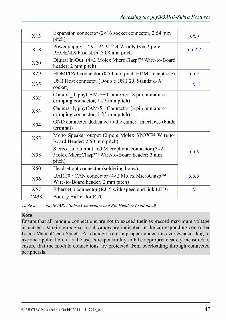
X13 Expansion connector (2×16 socket connector, 2.54 mm pitch) 4.6.4
X18 Power supply 12 V - 24 V / 24 W only (via 2-pole PHOENIX base strip; 5.08 mm pitch) 3.3.1.1
X20 Digital In/Out (4×2 Molex MicroClasp™ Wire-to-Board header; 2 mm pitch)
X29 HDMI/DVI connector (0.50 mm pitch HDMI receptacle) 3.3.7
X35 USB Host connector (Double USB 2.0 Standard-A socket) 0
X52 Camera_0, phyCAM-S+ Connector (8 pin miniature crimping connector, 1.25 mm pitch)
X53 Camera_1, phyCAM-S+ Connector (8 pin miniature crimping connector, 1.25 mm pitch)
X54 GND connector dedicated to the camera interfaces (blade terminal)
X55 Mono Speaker output (2-pole Molex SPOX™ Wire-to-Board Header; 2.50 mm pitch)
X58 Stereo Line In/Out and Microphone connector (5×2 Molex MicroClasp™ Wire-to-Board header; 2 mm pitch)
X60 Headset out connector (soldering holes)
3.3.6
X56 UART0 / CAN connector (4×2 Molex MicroClasp™ Wire-to-Board header; 2 mm pitch)
3.3.3
X57 Ethernet 0 connector (RJ45 with speed and link LED) 0 C438 Battery Buffer for RTC
Table 2: phyBOARD-Subra Connectors and Pin Headers (continued)
Note: Ensure that all module connections are not to exceed their expressed maximum voltage or current. Maximum signal input values are indicated in the corresponding controller User's Manual/Data Sheets. As damage from improper connections varies according to use and application, it is the user‘s responsibility to take appropriate safety measures to ensure that the module connections are protected from overloading through connected peripherals.
phyBOARD-Subra-i.MX 6 [PB-00601-xxx]
48 © PHYTEC Messtechnik GmbH 2014 L-794e_0
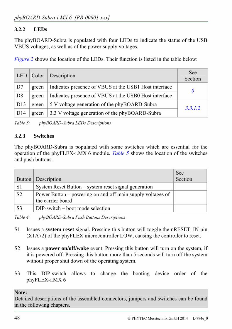
3.2.2 LEDs
The phyBOARD-Subra is populated with four LEDs to indicate the status of the USB VBUS voltages, as well as of the power supply voltages. Figure 2 shows the location of the LEDs. Their function is listed in the table below:
LED Color Description See Section
D7 green Indicates presence of VBUS at the USB1 Host interface D8 green Indicates presence of VBUS at the USB0 Host interface
0
D13 green 5 V voltage generation of the phyBOARD-Subra D14 green 3.3 V voltage generation of the phyBOARD-Subra
3.3.1.2
Table 3: phyBOARD-Subra LEDs Descriptions
3.2.3 Switches
The phyBOARD-Subra is populated with some switches which are essential for the operation of the phyFLEX-i.MX 6 module. Table 5 shows the location of the switches and push buttons.
Button Description See Section
S1 System Reset Button – system reset signal generation S2 Power Button – powering on and off main supply voltages of
the carrier board
S3 DIP-switch – boot mode selection Table 4: phyBOARD-Subra Push Buttons Descriptions S1 Issues a system reset signal. Pressing this button will toggle the nRESET_IN pin
(X1A72) of the phyFLEX microcontroller LOW, causing the controller to reset. S2 Issues a power on/off/wake event. Pressing this button will turn on the system, if
it is powered off. Pressing this button more than 5 seconds will turn off the system without proper shut down of the operating system.
S3 This DIP-switch allows to change the booting device order of the
phyFLEX-i.MX 6 Note: Detailed descriptions of the assembled connectors, jumpers and switches can be found in the following chapters.
Accessing the phyBOARD-Subra Features
© PHYTEC Messtechnik GmbH 2014 L-794e_0 49
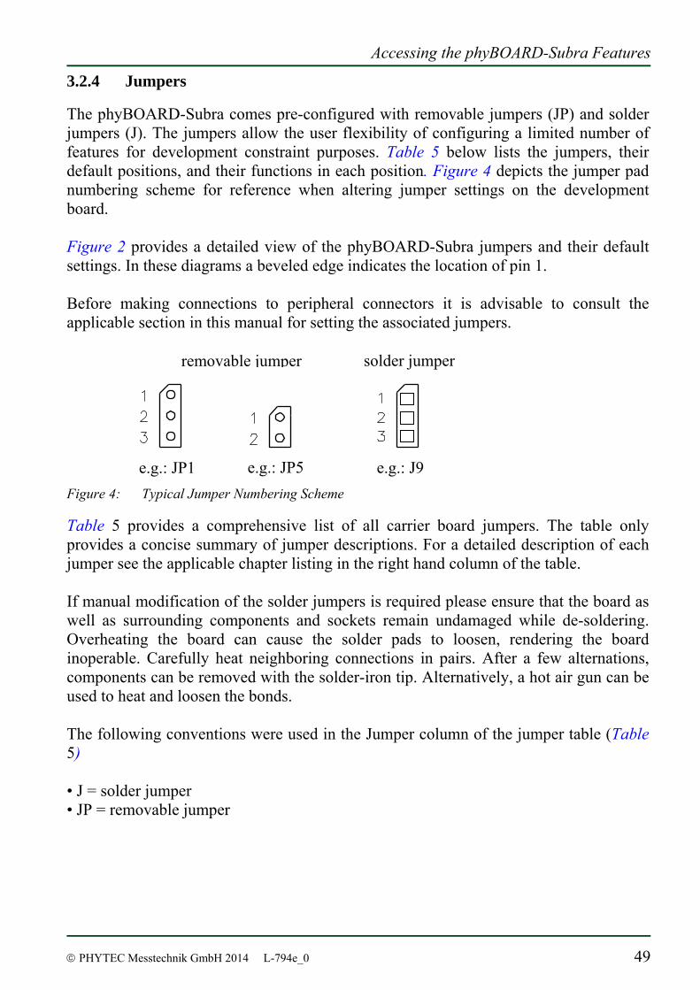
3.2.4 Jumpers
The phyBOARD-Subra comes pre-configured with removable jumpers (JP) and solder jumpers (J). The jumpers allow the user flexibility of configuring a limited number of features for development constraint purposes. Table 5 below lists the jumpers, their default positions, and their functions in each position. Figure 4 depicts the jumper pad numbering scheme for reference when altering jumper settings on the development board. Figure 2 provides a detailed view of the phyBOARD-Subra jumpers and their default settings. In these diagrams a beveled edge indicates the location of pin 1. Before making connections to peripheral connectors it is advisable to consult the applicable section in this manual for setting the associated jumpers.
Figure 4: Typical Jumper Numbering Scheme
Table 5 provides a comprehensive list of all carrier board jumpers. The table only provides a concise summary of jumper descriptions. For a detailed description of each jumper see the applicable chapter listing in the right hand column of the table. If manual modification of the solder jumpers is required please ensure that the board as well as surrounding components and sockets remain undamaged while de-soldering. Overheating the board can cause the solder pads to loosen, rendering the board inoperable. Carefully heat neighboring connections in pairs. After a few alternations, components can be removed with the solder-iron tip. Alternatively, a hot air gun can be used to heat and loosen the bonds. The following conventions were used in the Jumper column of the jumper table (Table 5) • J = solder jumper • JP = removable jumper
e.g.: J9e.g.: JP1 e.g.: JP5
solder jumperremovable jumper
phyBOARD-Subra-i.MX 6 [PB-00601-xxx]
50 © PHYTEC Messtechnik GmbH 2014 L-794e_0
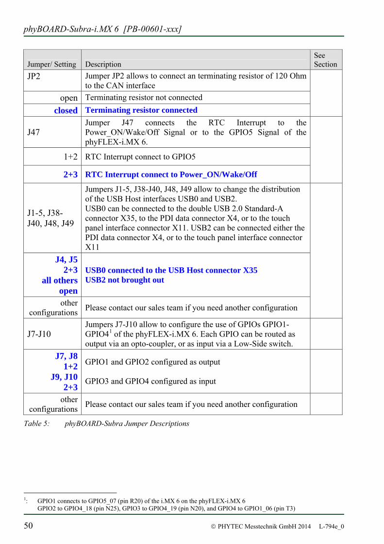
Jumper/ Setting Description See Section
JP2 Jumper JP2 allows to connect an terminating resistor of 120 Ohm to the CAN interface
open Terminating resistor not connected closed Terminating resistor connected
J47 Jumper J47 connects the RTC Interrupt to the Power_ON/Wake/Off Signal or to the GPIO5 Signal of the phyFLEX-i.MX 6.
1+2 RTC Interrupt connect to GPIO5
2+3 RTC Interrupt connect to Power_ON/Wake/Off
J1-5, J38-J40, J48, J49
Jumpers J1-5, J38-J40, J48, J49 allow to change the distribution of the USB Host interfaces USB0 and USB2. USB0 can be connected to the double USB 2.0 Standard-A connector X35, to the PDI data connector X4, or to the touch panel interface connector X11. USB2 can be connected either the PDI data connector X4, or to the touch panel interface connector X11
J4, J5 2+3
all others open
USB0 connected to the USB Host connector X35 USB2 not brought out
other configurations Please contact our sales team if you need another configuration
J7-J10 Jumpers J7-J10 allow to configure the use of GPIOs GPIO1-GPIO41 of the phyFLEX-i.MX 6. Each GPIO can be routed as output via an opto-coupler, or as input via a Low-Side switch.
J7, J8 1+2
J9, J10 2+3
GPIO1 and GPIO2 configured as output GPIO3 and GPIO4 configured as input
other configurations Please contact our sales team if you need another configuration
Table 5: phyBOARD-Subra Jumper Descriptions
1: GPIO1 connects to GPIO5_07 (pin R20) of the i.MX 6 on the phyFLEX-i.MX 6
GPIO2 to GPIO4_18 (pin N25), GPIO3 to GPIO4_19 (pin N20), and GPIO4 to GPIO1_06 (pin T3)
Accessing the phyBOARD-Subra Features
© PHYTEC Messtechnik GmbH 2014 L-794e_0 51
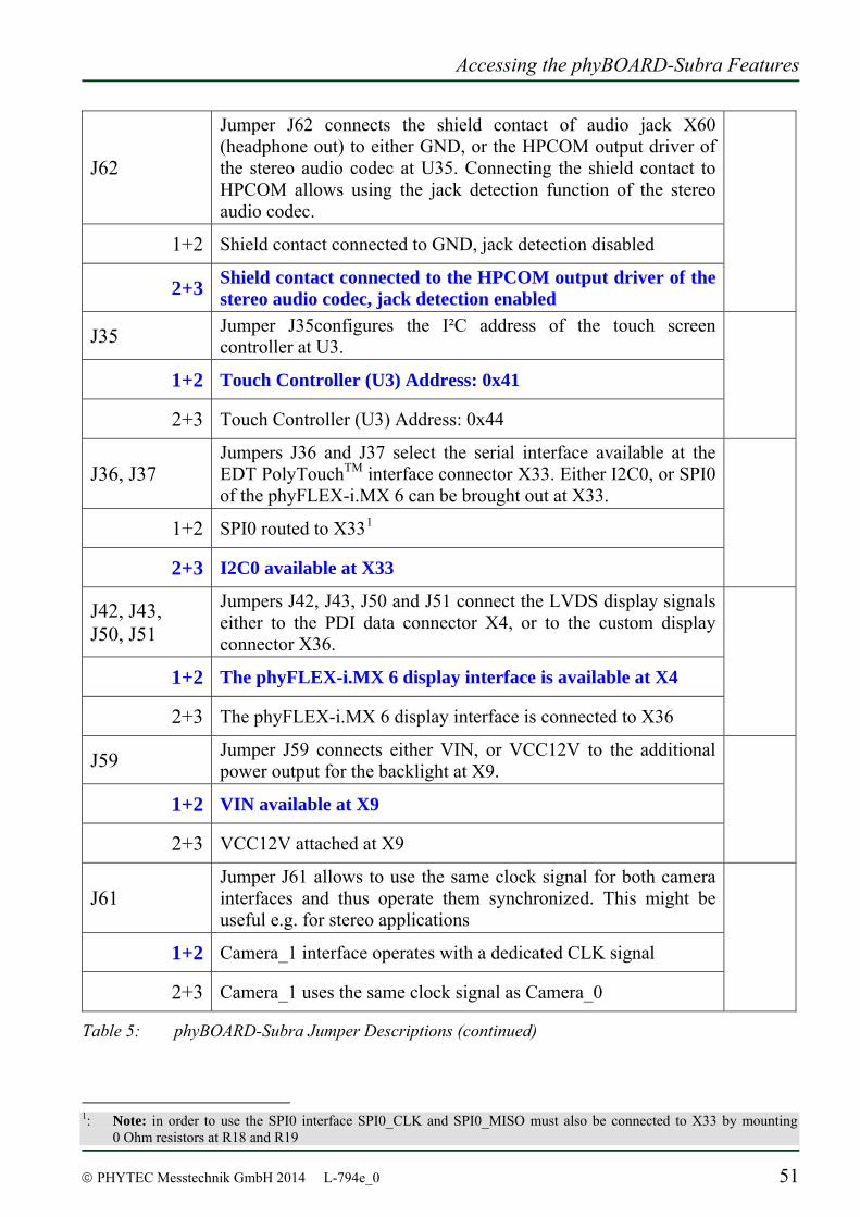
J62
Jumper J62 connects the shield contact of audio jack X60 (headphone out) to either GND, or the HPCOM output driver of the stereo audio codec at U35. Connecting the shield contact to HPCOM allows using the jack detection function of the stereo audio codec.
1+2 Shield contact connected to GND, jack detection disabled
2+3 Shield contact connected to the HPCOM output driver of the stereo audio codec, jack detection enabled
J35 Jumper J35configures the I²C address of the touch screen controller at U3.
1+2 Touch Controller (U3) Address: 0x41
2+3 Touch Controller (U3) Address: 0x44
J36, J37 Jumpers J36 and J37 select the serial interface available at the EDT PolyTouchTM interface connector X33. Either I2C0, or SPI0 of the phyFLEX-i.MX 6 can be brought out at X33.
1+2 SPI0 routed to X331
2+3 I2C0 available at X33
J42, J43, J50, J51
Jumpers J42, J43, J50 and J51 connect the LVDS display signals either to the PDI data connector X4, or to the custom display connector X36.
1+2 The phyFLEX-i.MX 6 display interface is available at X4
2+3 The phyFLEX-i.MX 6 display interface is connected to X36
J59 Jumper J59 connects either VIN, or VCC12V to the additional power output for the backlight at X9.
1+2 VIN available at X9
2+3 VCC12V attached at X9
J61 Jumper J61 allows to use the same clock signal for both camera interfaces and thus operate them synchronized. This might be useful e.g. for stereo applications
1+2 Camera_1 interface operates with a dedicated CLK signal
2+3 Camera_1 uses the same clock signal as Camera_0
Table 5: phyBOARD-Subra Jumper Descriptions (continued)
1: Note: in order to use the SPI0 interface SPI0_CLK and SPI0_MISO must also be connected to X33 by mounting
0 Ohm resistors at R18 and R19

phyBOARD-Subra-i.MX 6 [PB-00601-xxx]
52 © PHYTEC Messtechnik GmbH 2014 L-794e_0
3.3 Functional Components on the phyBOARD-Subra Board
This section describes the functional components of the phyBOARD-Subra. Each subsection details a particular connector/interface and associated jumpers for configuring that interface.
3.3.1 Power Supply
Caution: Do not change modules or jumper settings while the phyBOARD-Subra is supplied with power!
3.3.1.1 Power Connectors (X18)
Connector X18 is the primary input power supply connector of the phyBOARD-Subra. X18 is a 2-pole PHOENIX base strip 5.08 mm connector suitable for a single supply voltage of up to 24 V / 1 A. The required current load capacity for all power supply solutions depends on the specific configuration of the phyFLEX mounted on the phyBOARD-Subra the particular interfaces enabled while executing software as well as whether an optional expansion board is connected to the carrier board. A 24 V adapter with a minimum supply of 1 A is recommended.
Figure 5: Power Supply Connectors
3.3.1.2 Power LEDs D13 and D14
The green LEDs D13 and D14 (see Figure 2) indicate the presence of the 3.3 V (D14) and 5 V (D13) supply voltage generated from input voltage.
PHOENIX base strip
Accessing the phyBOARD-Subra Features
© PHYTEC Messtechnik GmbH 2014 L-794e_0 53
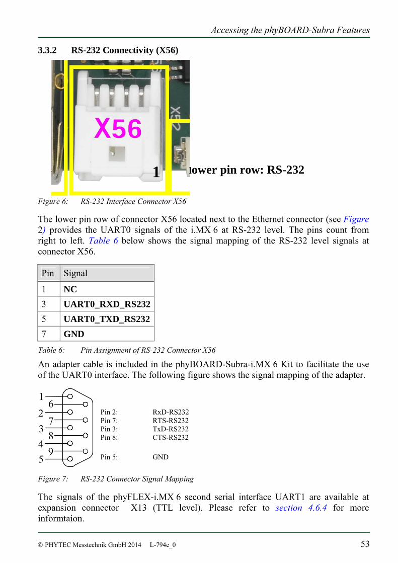
3.3.2 RS-232 Connectivity (X56)
Figure 6: RS-232 Interface Connector X56 The lower pin row of connector X56 located next to the Ethernet connector (see Figure 2) provides the UART0 signals of the i.MX 6 at RS-232 level. The pins count from right to left. Table 6 below shows the signal mapping of the RS-232 level signals at connector X56.
Pin Signal
1 NC 3 UART0_RXD_RS232 5 UART0_TXD_RS232 7 GND
Table 6: Pin Assignment of RS-232 Connector X56
An adapter cable is included in the phyBOARD-Subra-i.MX 6 Kit to facilitate the use of the UART0 interface. The following figure shows the signal mapping of the adapter.
Pin 2: RxD-RS232 Pin 7: RTS-RS232 Pin 3: TxD-RS232 Pin 8: CTS-RS232 Pin 5: GND
Figure 7: RS-232 Connector Signal Mapping
The signals of the phyFLEX-i.MX 6 second serial interface UART1 are available at expansion connector X13 (TTL level). Please refer to section 4.6.4 for more informtaion.
1 2 3 4
7 6
5
8 9
lower pin row: RS-232 1
phyBOARD-Subra-i.MX 6 [PB-00601-xxx]
54 © PHYTEC Messtechnik GmbH 2014 L-794e_0
3.3.2.1 Software Implementation
In order to use UART0 at connector 56 /dev/ttymxc3 has been implemented within the BSP. It acts as the standard console. It’s mainly used for debugging and control of software updates.
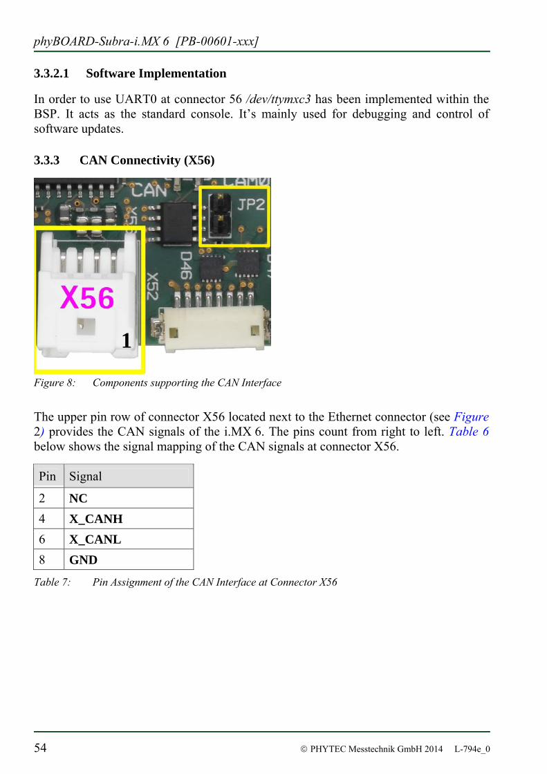
3.3.3 CAN Connectivity (X56)
Figure 8: Components supporting the CAN Interface
The upper pin row of connector X56 located next to the Ethernet connector (see Figure 2) provides the CAN signals of the i.MX 6. The pins count from right to left. Table 6 below shows the signal mapping of the CAN signals at connector X56.
Pin Signal
2 NC 4 X_CANH 6 X_CANL 8 GND
Table 7: Pin Assignment of the CAN Interface at Connector X56
1
Accessing the phyBOARD-Subra Features
© PHYTEC Messtechnik GmbH 2014 L-794e_0 55
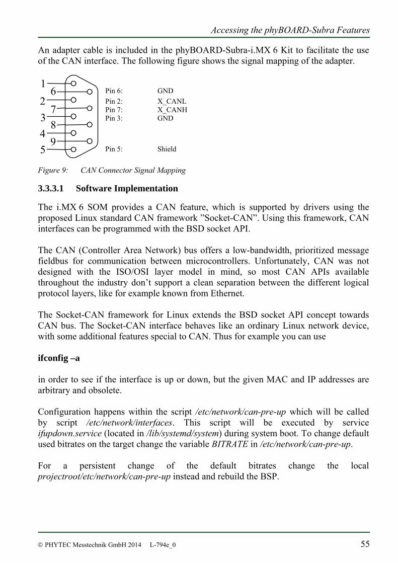
An adapter cable is included in the phyBOARD-Subra-i.MX 6 Kit to facilitate the use of the CAN interface. The following figure shows the signal mapping of the adapter.
Pin 6: GND Pin 2: X_CANL Pin 7: X_CANH Pin 3: GND Pin 5: Shield
Figure 9: CAN Connector Signal Mapping
3.3.3.1 Software Implementation
The i.MX 6 SOM provides a CAN feature, which is supported by drivers using the proposed Linux standard CAN framework ”Socket-CAN”. Using this framework, CAN interfaces can be programmed with the BSD socket API. The CAN (Controller Area Network) bus offers a low-bandwidth, prioritized message fieldbus for communication between microcontrollers. Unfortunately, CAN was not designed with the ISO/OSI layer model in mind, so most CAN APIs available throughout the industry don’t support a clean separation between the different logical protocol layers, like for example known from Ethernet. The Socket-CAN framework for Linux extends the BSD socket API concept towards CAN bus. The Socket-CAN interface behaves like an ordinary Linux network device, with some additional features special to CAN. Thus for example you can use ifconfig –a in order to see if the interface is up or down, but the given MAC and IP addresses are arbitrary and obsolete. Configuration happens within the script /etc/network/can-pre-up which will be called by script /etc/network/interfaces. This script will be executed by service ifupdown.service (located in /lib/systemd/system) during system boot. To change default used bitrates on the target change the variable BITRATE in /etc/network/can-pre-up. For a persistent change of the default bitrates change the local projectroot/etc/network/can-pre-up instead and rebuild the BSP.
1 2 3 4
7 6
5
8 9
phyBOARD-Subra-i.MX 6 [PB-00601-xxx]
56 © PHYTEC Messtechnik GmbH 2014 L-794e_0
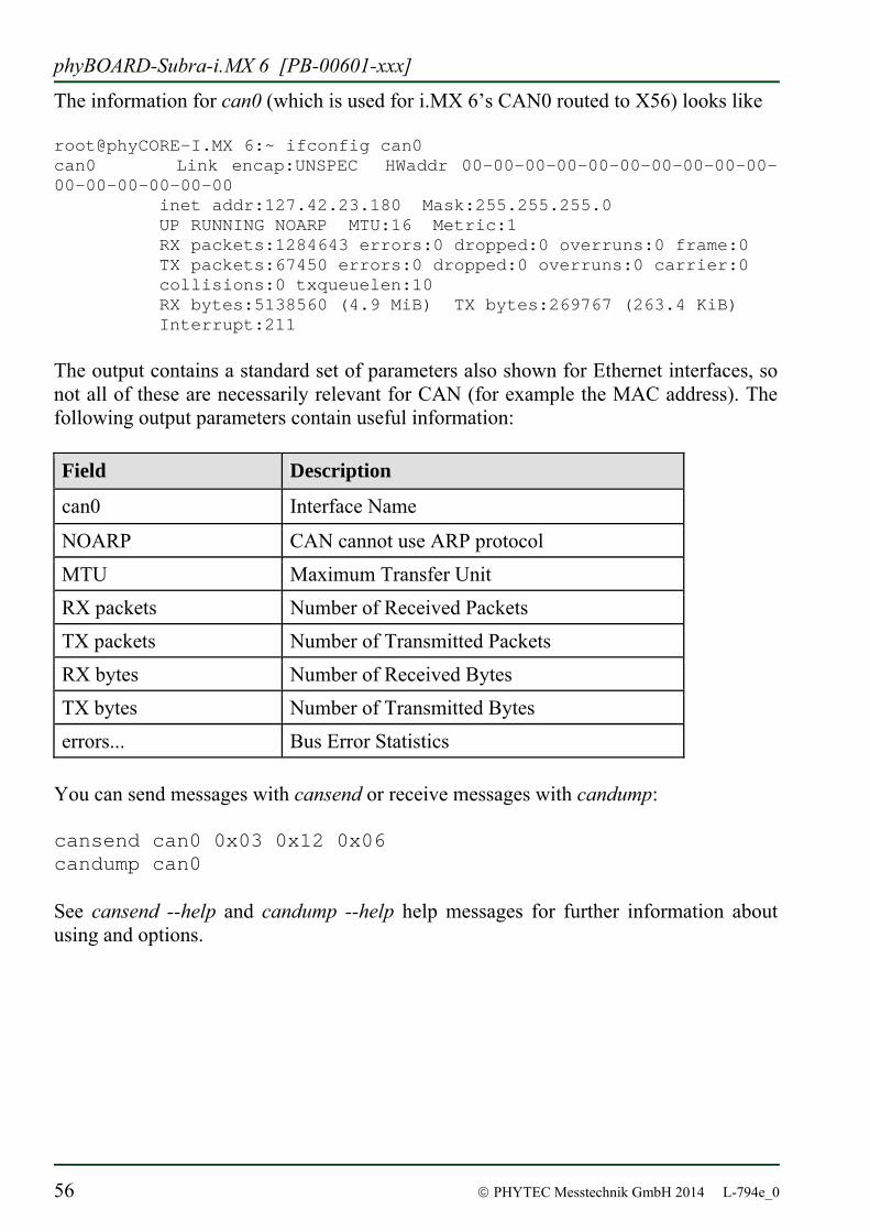
The information for can0 (which is used for i.MX 6’s CAN0 routed to X56) looks like [email protected] 6:~ ifconfig can0 can0 Link encap:UNSPEC HWaddr 00-00-00-00-00-00-00-00-00-00-00-00-00-00-00-00 inet addr:127.42.23.180 Mask:255.255.255.0 UP RUNNING NOARP MTU:16 Metric:1 RX packets:1284643 errors:0 dropped:0 overruns:0 frame:0 TX packets:67450 errors:0 dropped:0 overruns:0 carrier:0 collisions:0 txqueuelen:10 RX bytes:5138560 (4.9 MiB) TX bytes:269767 (263.4 KiB) Interrupt:211 The output contains a standard set of parameters also shown for Ethernet interfaces, so not all of these are necessarily relevant for CAN (for example the MAC address). The following output parameters contain useful information: Field Description
can0 Interface Name
NOARP CAN cannot use ARP protocol MTU Maximum Transfer Unit RX packets Number of Received Packets TX packets Number of Transmitted Packets RX bytes Number of Received Bytes TX bytes Number of Transmitted Bytes errors... Bus Error Statistics
You can send messages with cansend or receive messages with candump: cansend can0 0x03 0x12 0x06 candump can0 See cansend --help and candump --help help messages for further information about using and options.
Accessing the phyBOARD-Subra Features
© PHYTEC Messtechnik GmbH 2014 L-794e_0 57
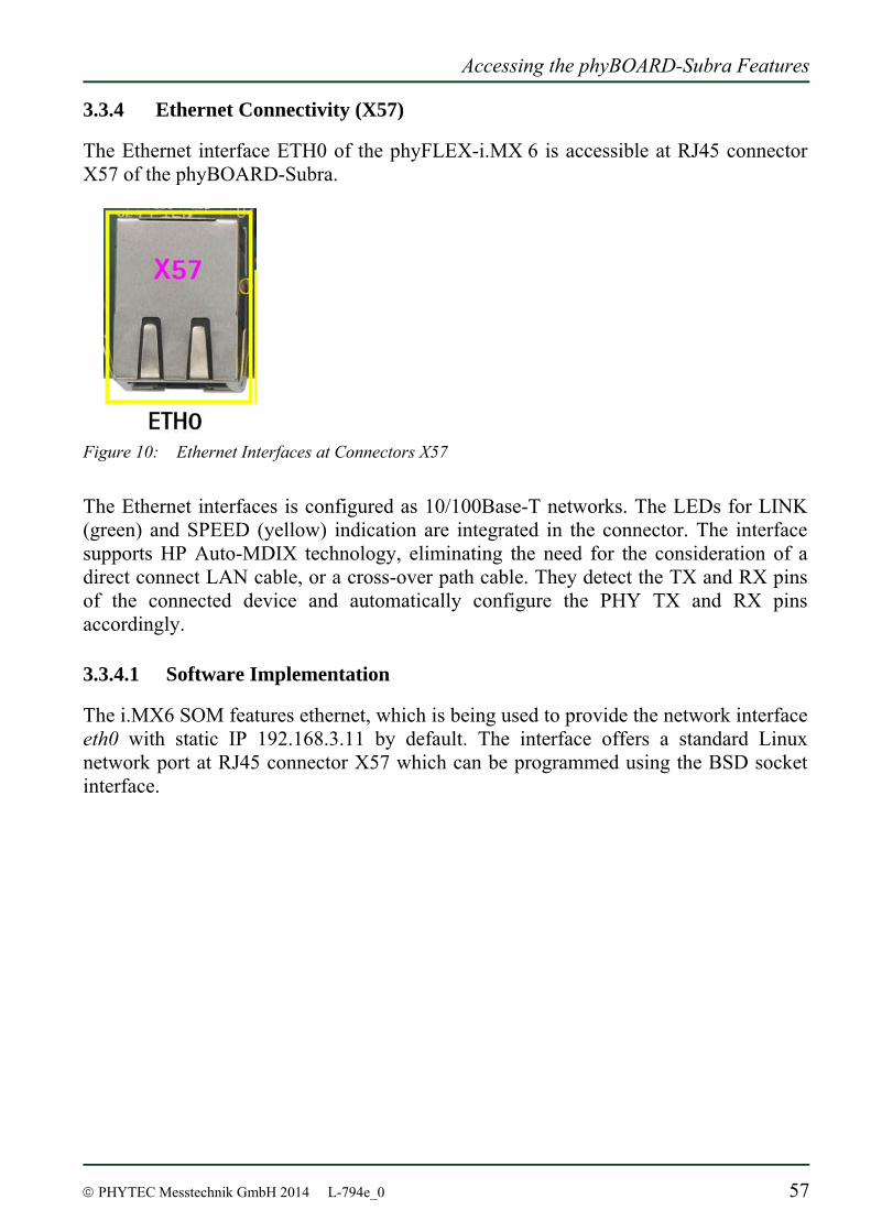
3.3.4 Ethernet Connectivity (X57)
The Ethernet interface ETH0 of the phyFLEX-i.MX 6 is accessible at RJ45 connector X57 of the phyBOARD-Subra.
Figure 10: Ethernet Interfaces at Connectors X57
The Ethernet interfaces is configured as 10/100Base-T networks. The LEDs for LINK (green) and SPEED (yellow) indication are integrated in the connector. The interface supports HP Auto-MDIX technology, eliminating the need for the consideration of a direct connect LAN cable, or a cross-over path cable. They detect the TX and RX pins of the connected device and automatically configure the PHY TX and RX pins accordingly.
3.3.4.1 Software Implementation
The i.MX6 SOM features ethernet, which is being used to provide the network interface eth0 with static IP 192.168.3.11 by default. The interface offers a standard Linux network port at RJ45 connector X57 which can be programmed using the BSD socket interface.
phyBOARD-Subra-i.MX 6 [PB-00601-xxx]
58 © PHYTEC Messtechnik GmbH 2014 L-794e_0
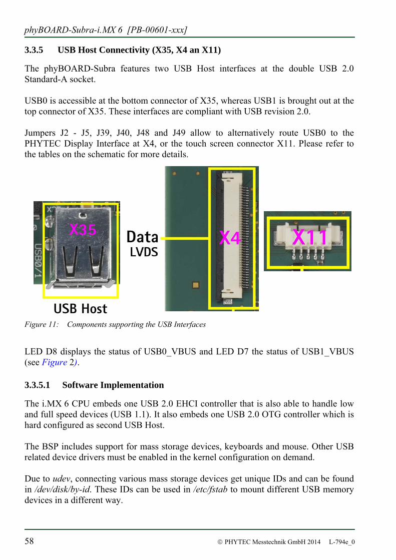
3.3.5 USB Host Connectivity (X35, X4 an X11)
The phyBOARD-Subra features two USB Host interfaces at the double USB 2.0 Standard-A socket. USB0 is accessible at the bottom connector of X35, whereas USB1 is brought out at the top connector of X35. These interfaces are compliant with USB revision 2.0. Jumpers J2 - J5, J39, J40, J48 and J49 allow to alternatively route USB0 to the PHYTEC Display Interface at X4, or the touch screen connector X11. Please refer to the tables on the schematic for more details.
Figure 11: Components supporting the USB Interfaces
LED D8 displays the status of USB0_VBUS and LED D7 the status of USB1_VBUS (see Figure 2).
3.3.5.1 Software Implementation
The i.MX 6 CPU embeds one USB 2.0 EHCI controller that is also able to handle low and full speed devices (USB 1.1). It also embeds one USB 2.0 OTG controller which is hard configured as second USB Host. The BSP includes support for mass storage devices, keyboards and mouse. Other USB related device drivers must be enabled in the kernel configuration on demand. Due to udev, connecting various mass storage devices get unique IDs and can be found in /dev/disk/by-id. These IDs can be used in /etc/fstab to mount different USB memory devices in a different way.
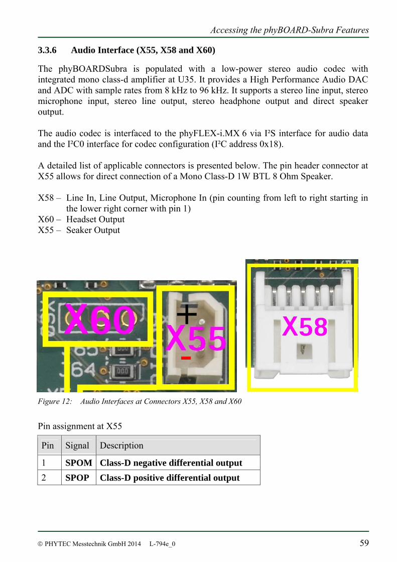
Accessing the phyBOARD-Subra Features
© PHYTEC Messtechnik GmbH 2014 L-794e_0 59
3.3.6 Audio Interface (X55, X58 and X60)
The phyBOARDSubra is populated with a low-power stereo audio codec with integrated mono class-d amplifier at U35. It provides a High Performance Audio DAC and ADC with sample rates from 8 kHz to 96 kHz. It supports a stereo line input, stereo microphone input, stereo line output, stereo headphone output and direct speaker output. The audio codec is interfaced to the phyFLEX-i.MX 6 via I²S interface for audio data and the I²C0 interface for codec configuration (I²C address 0x18). A detailed list of applicable connectors is presented below. The pin header connector at X55 allows for direct connection of a Mono Class-D 1W BTL 8 Ohm Speaker. X58 – Line In, Line Output, Microphone In (pin counting from left to right starting in
the lower right corner with pin 1) X60 – Headset Output X55 – Seaker Output
Figure 12: Audio Interfaces at Connectors X55, X58 and X60
Pin assignment at X55
Pin Signal Description
1 SPOM Class-D negative differential output 2 SPOP Class-D positive differential output
phyBOARD-Subra-i.MX 6 [PB-00601-xxx]
60 © PHYTEC Messtechnik GmbH 2014 L-794e_0
Pin assignment at X58
Pin Signal Pin Signal
1 Shield 2 AGND 3 LINE_IN_R 4 LINE_IN_L 5 LINE_OUT_R 6 LINE_OUT_L AGND 8 AGND 9 MIC_IN_R 10 MIC_IN_L
Pin assignment at X60
Pin Signal
1 HEAD_PHONE_L 2 HEAD_PHONE_R 3 HEAD_PHONE_COM
Please refer to the audio codec’s reference manual for additional information regarding the special interface specification.
3.3.6.1 Software Implementation
Audio support on the module is done via the I2S interface and controlled via I2C. On the phyBOARD-Subra the audio codec's registers can be accessed via the I2C0 interface at address 0x18 (7-bit MSB addressing). As of the printing of this manual the BSP delivered with the phyBOARD-Subra-i.MX 6 does not support the audio interfaces. Please visit the PHYTEC website for a road map of the BSP.
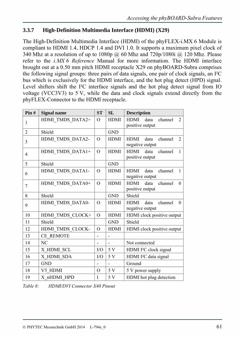
Accessing the phyBOARD-Subra Features
© PHYTEC Messtechnik GmbH 2014 L-794e_0 61
3.3.7 High-Definition Multimedia Interface (HDMI) (X29)
The High-Definition Multimedia Interface (HDMI) of the phyFLEX-i.MX 6 Module is compliant to HDMI 1.4, HDCP 1.4 and DVI 1.0. It supports a maximum pixel clock of 340 Mhz at a resolution of up to 1080p @ 60 Mhz and 720p/1080i @ 120 Mhz. Please refer to the i.MX 6 Reference Manual for more information. The HDMI interface brought out at a 0.50 mm pitch HDMI receptacle X29 on phyBOARD-Subra comprises the following signal groups: three pairs of data signals, one pair of clock signals, an I²C bus which is exclusively for the HDMI interface, and the hot plug detect (HPD) signal. Level shifters shift the I²C interface signals and the hot plug detect signal from IO voltage (VCC3V3) to 5 V, while the data and clock signals extend directly from the phyFLEX-Connector to the HDMI receptacle. Pin # Signal name ST SL Description
1 HDMI_TMDS_DATA2+ O HDMI HDMI data channel 2 positive output
2 Shield GND
3 HDMI_TMDS_DATA2- O HDMI HDMI data channel 2 negative output
4 HDMI_TMDS_DATA1+ O HDMI HDMI data channel 1 positive output
5 Shield GND
6 HDMI_TMDS_DATA1- O HDMI HDMI data channel 1 negative output
7 HDMI_TMDS_DATA0+ O HDMI HDMI data channel 0 positive output
8 Shield GND Shield
9 HDMI_TMDS_DATA0- O HDMI HDMI data channel 0 negative output
10 HDMI_TMDS_CLOCK+ O HDMI HDMI clock positive output 11 Shield GND Shield 12 HDMI_TMDS_CLOCK- O HDMI HDMI clock positive output 13 CE_REMOTE - - 14 NC - - Not connected 15 X_HDMI_SCL I/O 5 V HDMI I²C clock signal 16 X_HDMI_SDA I/O 5 V HDMI I²C data signal 17 GND - - Ground 18 V5_HDMI O 5 V 5 V power supply 19 X_nHDMI_HPD I 5 V HDMI hot plug detection
Table 8: HDMI/DVI Connector X40 Pinout
phyBOARD-Subra-i.MX 6 [PB-00601-xxx]
62 © PHYTEC Messtechnik GmbH 2014 L-794e_0
3.3.7.1 Software Implementation
This driver gains access to the display via device node /dev/fb0 for HDMI which is default. A simple test of the framebuffer feature can then be run with: fbtest This will show various pictures on the display. You can check your framebuffer resolution with the command fbset
fbset cannot be used to change display resolution or colour depth. Depending on the framebuffer device different kernel command line are mostly needed to do this.
Setting the resolution will be done within Barebox’s environment. Therefore within script /env/video/display you will find the lines #HDMI Resolution hdmi_res=1280x1024M@60 You’ll also find the lines # Set prim out put (hdmi/ldb) prim_out=hdmi In case that you want to select the display connector instead of the HDMI connector as /dev/fb0, just modify to prim_out=ldb
Because the i.MX6 on the module is a SOLO (i.e. single core version), it cannot access HDMI and display connector at the same time.
Accessing the phyBOARD-Subra Features
© PHYTEC Messtechnik GmbH 2014 L-794e_0 63
3.3.7.2 Using Qt
Nokia’s Qtopia is very commonly used for embedded systems and it’s supported by this BSP. Please visit http://qt.nokia.com in order to get all the documentation that are available about this powerful cross-platform GUI toolkit. Within the BSP come some demos that show what is possible with Qt version 4.7.4. They’re located in /usr/bin/qt4-demos. In order to try them you need to connect an USB mouse or USB keyboard to the board. Start demos with commands like: cd /usr/bin/qt4-demos spreadsheet/spreadsheet -qws Each of the Qt applications shows a standardized little green Qt-icon at its upper left side that offers standard window functions like minimize, maximize and close. Demo fluidlauncher will be started automatically after booting.
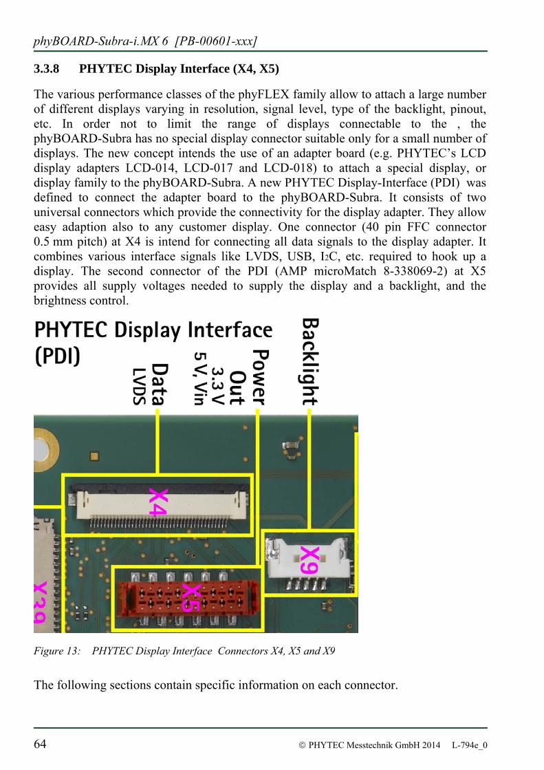
phyBOARD-Subra-i.MX 6 [PB-00601-xxx]
64 © PHYTEC Messtechnik GmbH 2014 L-794e_0
3.3.8 PHYTEC Display Interface (X4, X5)
The various performance classes of the phyFLEX family allow to attach a large number of different displays varying in resolution, signal level, type of the backlight, pinout, etc. In order not to limit the range of displays connectable to the , the phyBOARD-Subra has no special display connector suitable only for a small number of displays. The new concept intends the use of an adapter board (e.g. PHYTEC’s LCD display adapters LCD-014, LCD-017 and LCD-018) to attach a special display, or display family to the phyBOARD-Subra. A new PHYTEC Display-Interface (PDI) was defined to connect the adapter board to the phyBOARD-Subra. It consists of two universal connectors which provide the connectivity for the display adapter. They allow easy adaption also to any customer display. One connector (40 pin FFC connector 0.5 mm pitch) at X4 is intend for connecting all data signals to the display adapter. It combines various interface signals like LVDS, USB, I2C, etc. required to hook up a display. The second connector of the PDI (AMP microMatch 8-338069-2) at X5 provides all supply voltages needed to supply the display and a backlight, and the brightness control.
Figure 13: PHYTEC Display Interface Connectors X4, X5 and X9
The following sections contain specific information on each connector.
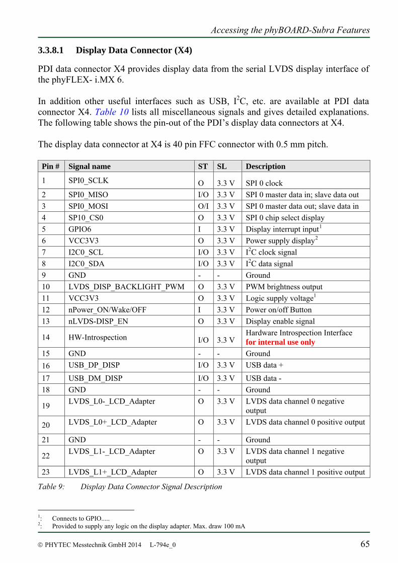
Accessing the phyBOARD-Subra Features
© PHYTEC Messtechnik GmbH 2014 L-794e_0 65
3.3.8.1 Display Data Connector (X4)
PDI data connector X4 provides display data from the serial LVDS display interface of the phyFLEX- i.MX 6. In addition other useful interfaces such as USB, I2C, etc. are available at PDI data connector X4. Table 10 lists all miscellaneous signals and gives detailed explanations. The following table shows the pin-out of the PDI’s display data connectors at X4. The display data connector at X4 is 40 pin FFC connector with 0.5 mm pitch. Pin # Signal name ST SL Description
1 SPI0_SCLK O 3.3 V SPI 0 clock 2 SPI0_MISO I/O 3.3 V SPI 0 master data in; slave data out 3 SPI0_MOSI O/I 3.3 V SPI 0 master data out; slave data in 4 SP10_CS0 O 3.3 V SPI 0 chip select display 5 GPIO6 I 3.3 V Display interrupt input1 6 VCC3V3 O 3.3 V Power supply display2 7 I2C0_SCL I/O 3.3 V I2C clock signal 8 I2C0_SDA I/O 3.3 V I2C data signal 9 GND - - Ground 10 LVDS_DISP_BACKLIGHT_PWM O 3.3 V PWM brightness output 11 VCC3V3 O 3.3 V Logic supply voltage1 12 nPower_ON/Wake/OFF I 3.3 V Power on/off Button 13 nLVDS-DISP_EN O 3.3 V Display enable signal
14 HW-Introspection I/O 3.3 V Hardware Introspection Interface for internal use only
15 GND - - Ground 16 USB_DP_DISP I/O 3.3 V USB data +
17 USB_DM_DISP I/O 3.3 V USB data - 18 GND - - Ground
19 LVDS_L0-_LCD_Adapter O 3.3 V LVDS data channel 0 negative output
20 LVDS_L0+_LCD_Adapter O 3.3 V LVDS data channel 0 positive output
21 GND - - Ground
22 LVDS_L1-_LCD_Adapter O 3.3 V LVDS data channel 1 negative output
23 LVDS_L1+_LCD_Adapter O 3.3 V LVDS data channel 1 positive output
Table 9: Display Data Connector Signal Description
1: Connects to GPIO..... 2: Provided to supply any logic on the display adapter. Max. draw 100 mA
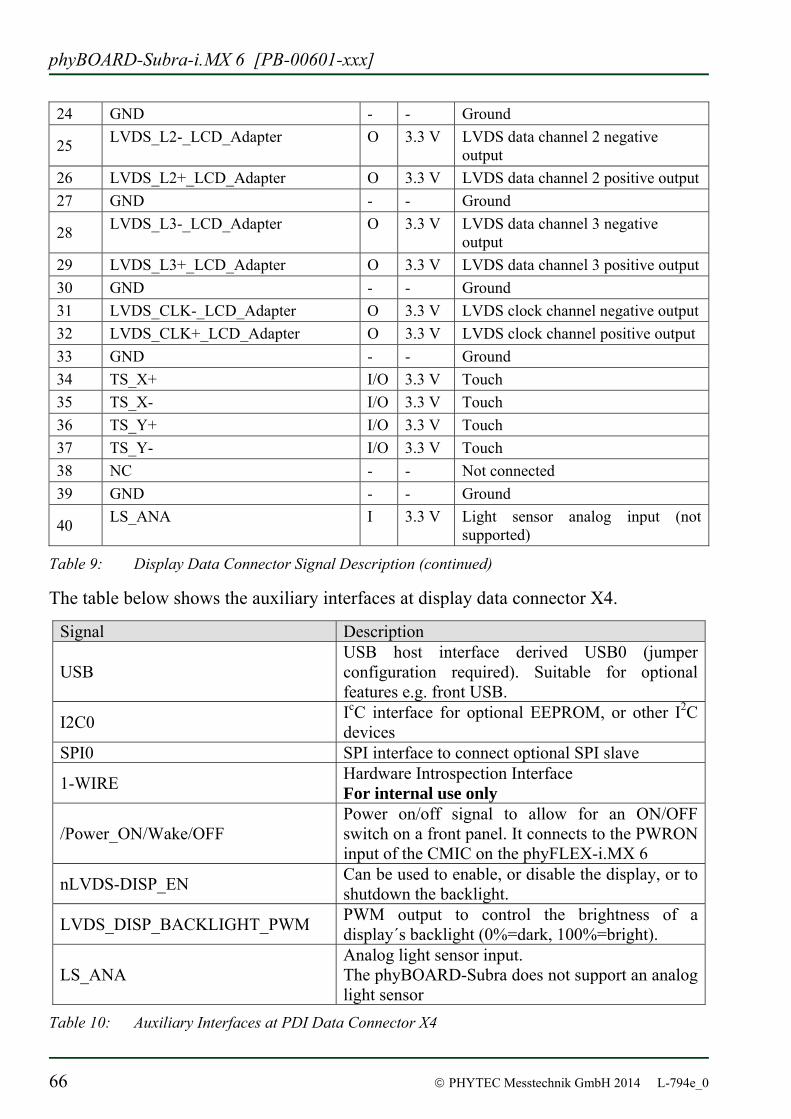
phyBOARD-Subra-i.MX 6 [PB-00601-xxx]
66 © PHYTEC Messtechnik GmbH 2014 L-794e_0
24 GND - - Ground
25 LVDS_L2-_LCD_Adapter O 3.3 V LVDS data channel 2 negative output
26 LVDS_L2+_LCD_Adapter O 3.3 V LVDS data channel 2 positive output 27 GND - - Ground
28 LVDS_L3-_LCD_Adapter O 3.3 V LVDS data channel 3 negative output
29 LVDS_L3+_LCD_Adapter O 3.3 V LVDS data channel 3 positive output 30 GND - - Ground 31 LVDS_CLK-_LCD_Adapter O 3.3 V LVDS clock channel negative output 32 LVDS_CLK+_LCD_Adapter O 3.3 V LVDS clock channel positive output 33 GND - - Ground 34 TS_X+ I/O 3.3 V Touch 35 TS_X- I/O 3.3 V Touch 36 TS_Y+ I/O 3.3 V Touch 37 TS_Y- I/O 3.3 V Touch 38 NC - - Not connected 39 GND - - Ground
40 LS_ANA I 3.3 V Light sensor analog input (not supported)
Table 9: Display Data Connector Signal Description (continued)
The table below shows the auxiliary interfaces at display data connector X4.
Signal Description
USB USB host interface derived USB0 (jumper configuration required). Suitable for optional features e.g. front USB.
I2C0 IcC interface for optional EEPROM, or other I2C devices
SPI0 SPI interface to connect optional SPI slave
1-WIRE Hardware Introspection Interface For internal use only
/Power_ON/Wake/OFF Power on/off signal to allow for an ON/OFF switch on a front panel. It connects to the PWRON input of the CMIC on the phyFLEX-i.MX 6
nLVDS-DISP_EN Can be used to enable, or disable the display, or to shutdown the backlight.
LVDS_DISP_BACKLIGHT_PWM PWM output to control the brightness of a display´s backlight (0%=dark, 100%=bright).
LS_ANA Analog light sensor input. The phyBOARD-Subra does not support an analog light sensor
Table 10: Auxiliary Interfaces at PDI Data Connector X4
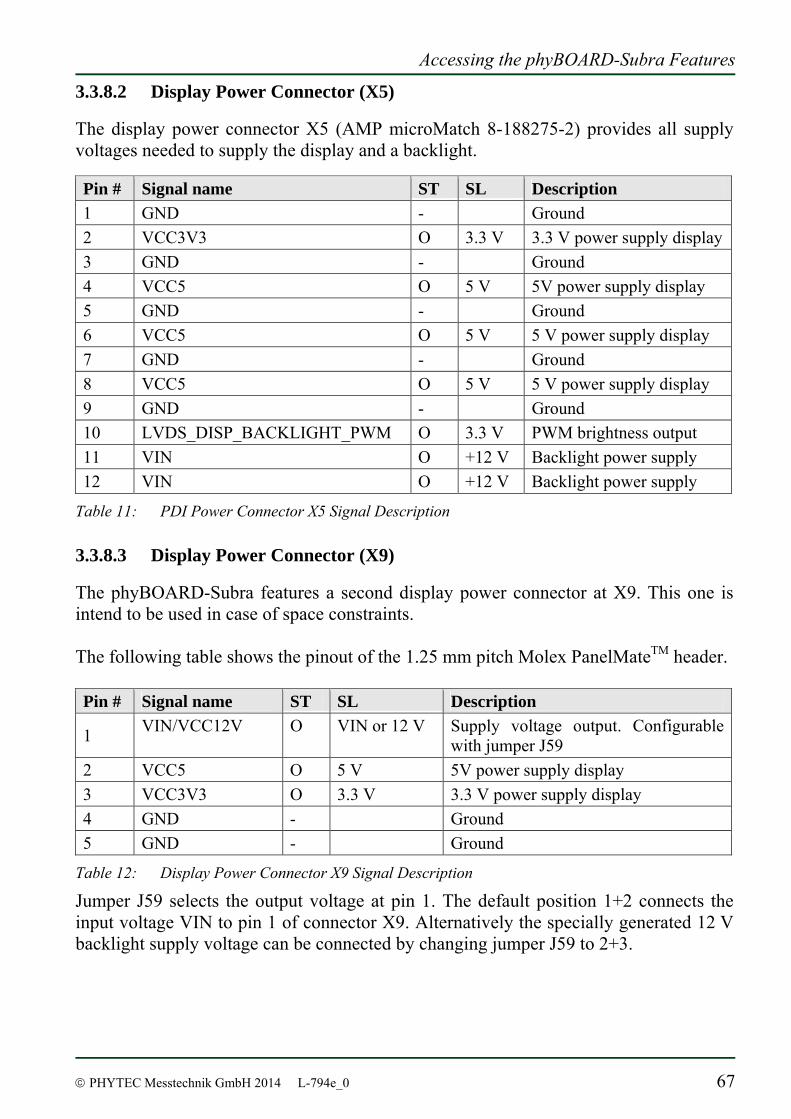
Accessing the phyBOARD-Subra Features
© PHYTEC Messtechnik GmbH 2014 L-794e_0 67
3.3.8.2 Display Power Connector (X5)
The display power connector X5 (AMP microMatch 8-188275-2) provides all supply voltages needed to supply the display and a backlight. Pin # Signal name ST SL Description 1 GND - Ground 2 VCC3V3 O 3.3 V 3.3 V power supply display 3 GND - Ground 4 VCC5 O 5 V 5V power supply display 5 GND - Ground 6 VCC5 O 5 V 5 V power supply display 7 GND - Ground 8 VCC5 O 5 V 5 V power supply display 9 GND - Ground 10 LVDS_DISP_BACKLIGHT_PWM O 3.3 V PWM brightness output 11 VIN O +12 V Backlight power supply 12 VIN O +12 V Backlight power supply
Table 11: PDI Power Connector X5 Signal Description
3.3.8.3 Display Power Connector (X9)
The phyBOARD-Subra features a second display power connector at X9. This one is intend to be used in case of space constraints. The following table shows the pinout of the 1.25 mm pitch Molex PanelMateTM header. Pin # Signal name ST SL Description
1 VIN/VCC12V O VIN or 12 V Supply voltage output. Configurable with jumper J59
2 VCC5 O 5 V 5V power supply display 3 VCC3V3 O 3.3 V 3.3 V power supply display 4 GND - Ground 5 GND - Ground
Table 12: Display Power Connector X9 Signal Description
Jumper J59 selects the output voltage at pin 1. The default position 1+2 connects the input voltage VIN to pin 1 of connector X9. Alternatively the specially generated 12 V backlight supply voltage can be connected by changing jumper J59 to 2+3.
phyBOARD-Subra-i.MX 6 [PB-00601-xxx]
68 © PHYTEC Messtechnik GmbH 2014 L-794e_0
3.3.8.4 Software Implementation
Because default setting for this BSP is to use the HDMI connector, using the display connector affords a modification within Barebox’s environment. Therefore within script /env/video/display you’ll find the lines: # Set prim out put (hdmi/ldb) prim_out=hdmi Please modify to: prim_out=ldb Within this script you’ll also find the possibility to select which display is attached. The BSP is already prepared for use with the PrimeView displays PD050VL1 (640x480), PD035VL1 (640x480), PD104SLF (800x600), PM070WL4 (800x480) and for the ETM0700G0DH6 (800x480). Simply modify comments of these lines: #Displays #display=Primeview-PD050VL1 #display=Primeview-PD035VL1 #display=Primeview-PD104SLF #display=Primeview-PM070WL4 display=ETM0700G0DH6 For further information about using a display see chapters 3.3.5.1 and 3.3.5.2.
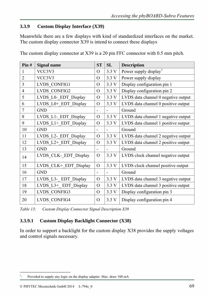
Accessing the phyBOARD-Subra Features
© PHYTEC Messtechnik GmbH 2014 L-794e_0 69
3.3.9 Custom Display Interface (X39)
Meanwhile there are a few displays with kind of standardized interfaces on the market. The custom display connector X39 is intend to connect these displays The custom display connector at X39 is a 20 pin FFC connector with 0.5 mm pitch. Pin # Signal name ST SL Description 1 VCC3V3 O 3.3 V Power supply display1 2 VCC3V3 O 3.3 V Power supply display 3 LVDS_CONFIG1 O 3.3 V Display configuration pin 1 4 LVDS_CONFIG2 O 3.3 V Display configuration pin 2 5 LVDS_L0-_EDT_Display O 3.3 V LVDS data channel 0 negative output 6 LVDS_L0+_EDT_Display O 3.3 V LVDS data channel 0 positive output 7 GND - - Ground 8 LVDS_L1-_EDT_Display O 3.3 V LVDS data channel 1 negative output 9 LVDS_L1+_EDT_Display O 3.3 V LVDS data channel 1 positive output 10 GND - - Ground 11 LVDS_L2-_EDT_Display O 3.3 V LVDS data channel 2 negative output 12 LVDS_L2+_EDT_Display O 3.3 V LVDS data channel 2 positive output 13 GND - - Ground
14 LVDS_CLK-_EDT_Display O 3.3 V LVDS clock channel negative output
15 LVDS_CLK+_EDT_Display O 3.3 V LVDS clock channel positive output 16 GND - - Ground 17 LVDS_L3-_ EDT_Display O 3.3 V LVDS data channel 3 negative output 18 LVDS_L3+_ EDT_Display O 3.3 V LVDS data channel 3 positive output 19 LVDS_CONFIG3 O 3.3 V Display configuration pin 3
20 LVDS_CONFIG4 O 3.3 V Display configuration pin 4
Table 13: Custom Display Connector Signal Description X39
3.3.9.1 Custom Display Backlight Connector (X38)
In order to support a backlight for the custom display X38 provides the supply voltages and control signals necessary.
1: Provided to supply any logic on the display adapter. Max. draw 100 mA
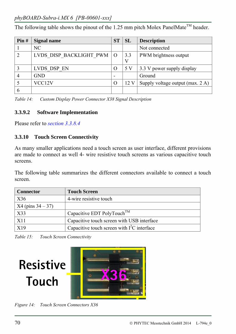
phyBOARD-Subra-i.MX 6 [PB-00601-xxx]
70 © PHYTEC Messtechnik GmbH 2014 L-794e_0
The following table shows the pinout of the 1.25 mm pitch Molex PanelMateTM header. Pin # Signal name ST SL Description 1 NC Not connected 2 LVDS_DISP_BACKLIGHT_PWM O 3.3
V PWM brightness output
3 LVDS_DSP_EN O 5 V 3.3 V power supply display 4 GND - Ground 5 VCC12V O 12 V Supply voltage output (max. 2 A) 6
Table 14: Custom Display Power Connector X38 Signal Description
3.3.9.2 Software Implementation
Please refer to section 3.3.8.4
3.3.10 Touch Screen Connectivity
As many smaller applications need a touch screen as user interface, different provisions are made to connect as well 4- wire resistive touch screens as various capacitive touch screens. The following table summarizes the different connectors available to connect a touch screen. Connector Touch Screen X36 4-wire resistive touch X4 (pins 34 – 37) X33 Capacitive EDT PolyTouchTM X11 Capacitive touch screen with USB interface X19 Capacitive touch screen with I2C interface
Table 15: Touch Screen Connectivity
Figure 14: Touch Screen Connectors X36
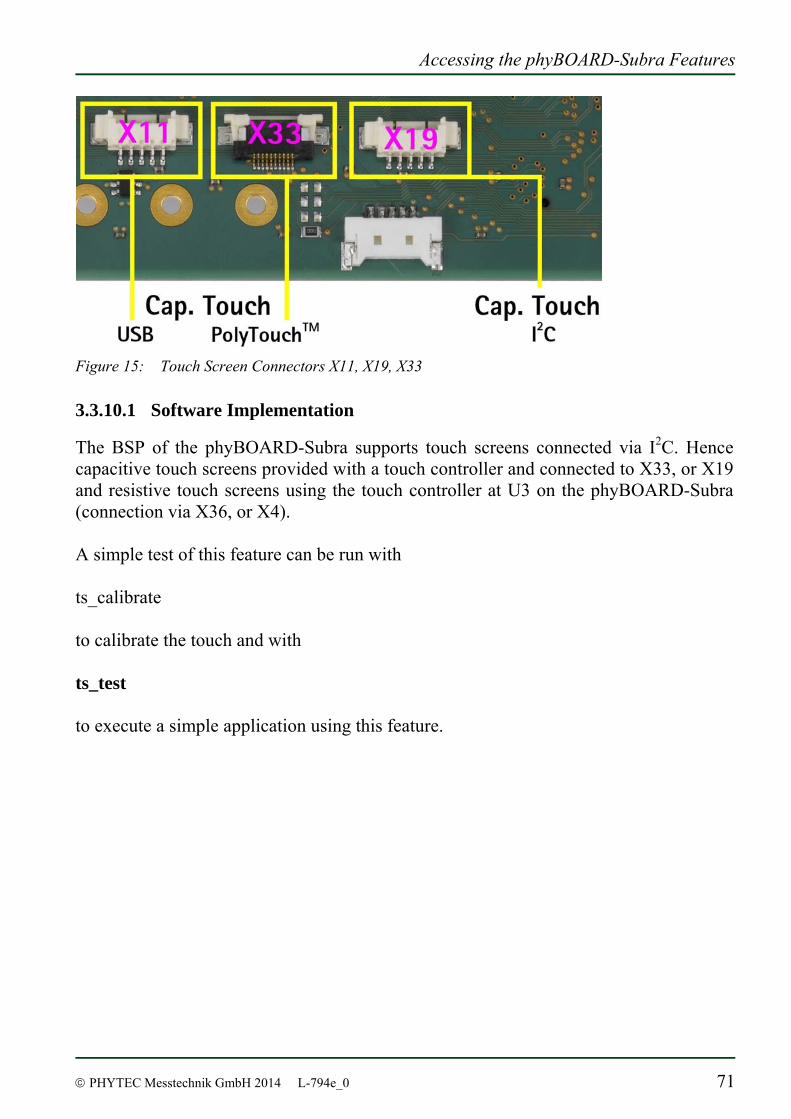
Accessing the phyBOARD-Subra Features
© PHYTEC Messtechnik GmbH 2014 L-794e_0 71
Figure 15: Touch Screen Connectors X11, X19, X33
3.3.10.1 Software Implementation
The BSP of the phyBOARD-Subra supports touch screens connected via I2C. Hence capacitive touch screens provided with a touch controller and connected to X33, or X19 and resistive touch screens using the touch controller at U3 on the phyBOARD-Subra (connection via X36, or X4). A simple test of this feature can be run with ts_calibrate to calibrate the touch and with ts_test to execute a simple application using this feature.
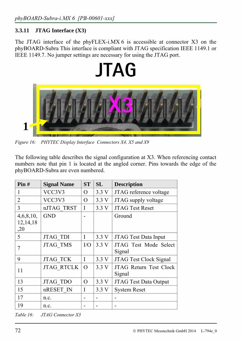
phyBOARD-Subra-i.MX 6 [PB-00601-xxx]
72 © PHYTEC Messtechnik GmbH 2014 L-794e_0
3.3.11 JTAG Interface (X3)
The JTAG interface of the phyFLEX-i.MX 6 is accessible at connector X3 on the phyBOARD-Subra This interface is compliant with JTAG specification IEEE 1149.1 or IEEE 1149.7. No jumper settings are necessary for using the JTAG port.
Figure 16: PHYTEC Display Interface Connectors X4, X5 and X9
The following table describes the signal configuration at X3. When referencing contact numbers note that pin 1 is located at the angled corner. Pins towards the edge of the phyBOARD-Subra are even numbered. Pin # Signal Name ST SL Description 1 VCC3V3 O 3.3 V JTAG reference voltage 2 VCC3V3 O 3.3 V JTAG supply voltage 3 nJTAG_TRST I 3.3 V JTAG Test Reset 4,6,8,10,12,14,18,20
GND - Ground
5 JTAG_TDI I 3.3 V JTAG Test Data Input
7 JTAG_TMS I/O 3.3 V JTAG Test Mode Select Signal
9 JTAG_TCK I 3.3 V JTAG Test Clock Signal
11 JTAG_RTCLK O 3.3 V JTAG Return Test Clock Signal
13 JTAG_TDO O 3.3 V JTAG Test Data Output 15 nRESET_IN I 3.3 V System Reset 17 n.c. - - - 19 n.c. - - -
Table 16: JTAG Connector X3
1
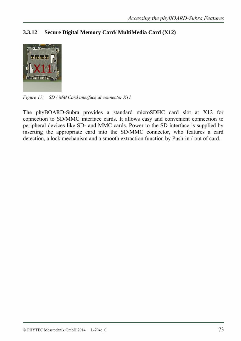
Accessing the phyBOARD-Subra Features
© PHYTEC Messtechnik GmbH 2014 L-794e_0 73
3.3.12 Secure Digital Memory Card/ MultiMedia Card (X12)
Figure 17: SD / MM Card interface at connector X11
The phyBOARD-Subra provides a standard microSDHC card slot at X12 for connection to SD/MMC interface cards. It allows easy and convenient connection to peripheral devices like SD- and MMC cards. Power to the SD interface is supplied by inserting the appropriate card into the SD/MMC connector, who features a card detection, a lock mechanism and a smooth extraction function by Push-in /-out of card.
phyBOARD-Subra-i.MX 6 [PB-00601-xxx]
74 © PHYTEC Messtechnik GmbH 2014 L-794e_0
3.3.12.1 Software Implementation
The phyBOARD-Subra supports a slot for Micro Secure Digital Cards and Micro Multi Media Cards to be used as general purpose blockdevices. These devices can be used in the same way as any other blockdevice.
These kind of devices are hot pluggable, so you must pay attention not to unplug the device while it’s still mounted. This may result in data loss.
After inserting an MMC/SD card, the kernel will generate new device nodes in /dev. The full device can be reached via its /dev/mmcblk0 device node, MMC/SD card partitions will occur in the following way: /dev/mmcblk0p<Y> <Y> counts as the partition number starting from 1 to the max count of partitions on this device.
These partition device nodes will only occur if the card contains a valid partition table (”hard disk” like handling). If it does not contain one, the whole device can be used for a filesystem (”floppy” like handling). In this case /dev/mmcblk0 must be used for formatting and mounting.
The partitions can be formatted with any kind of filesystem and also handled in a standard manner, e.g. the mount and umount command work as expected.
The cards are always mounted as being writable. Setting of write-protection of MMC/SD cards is not recognized.
In general the i.MX 6 processor on the phyFLEX-i.MX 6 can boot from an SD card. Please refer to section 4.4.
The phyBOARD-Subra-i.MX6 is configured for booting from NAND only! In order to be able to boot from SD card, you need to close solder jumpers R4 and R5!
Accessing the phyBOARD-Subra Features
© PHYTEC Messtechnik GmbH 2014 L-794e_0 75
3.3.13 RTC U8
The phyBOARD-Subra is equipped with an RTC RV-4162-C7 at U8. The RTC interrupt can be connected to either ... A Gold Cap 3.3.13.1 Software Implementation
The RTC on the phyBOARD-Subra can be accessed as /dev/rtc1. It also has the entry /sys/class/rtc/rtc1 in the sysfs file system, where you can read for example the name. Date and time can be manipulated with the hwclock tool, using the -w (systohc) and -s (hctosys) options. For more information about this tool refer to the manpage of hwclock. To set the date first use date (see man date on the PC) and then run hwclock -w -u to store the new date into the RTC. The internal RTC of the i.MX6 can be accessed as /dev/rtc2, but please note that it is not very precisely. /dev/rtc0 would be the internal RTC of the PMIC, but it is non-functional.
3.3.14 Boot Mode
The pyhBOARD-Subra has a defined boot sequence:
1. NAND 2. SD/MMC
The exact choosen boot mode in the processor is SYSBOOT[4:0] = 10011b : NAND, NANDI2C, MMC0, UART0
3.3.15 CPU core frequency Scaling The phyCORE-i.MX 6 supports dvfs (dynamic voltage and frequency scaling). Four different frequencies are supported. Type: cat /sys/devices/system/cpu/cpu0/cpufreq/scaling_available_frequencies and you’ll get them all listed. In case you have an AM3354 or AM3359 with a maximum of 800MHz these are: 300000 600000 720000 800000

phyBOARD-Subra-i.MX 6 [PB-00601-xxx]
76 © PHYTEC Messtechnik GmbH 2014 L-794e_0
The voltages are scaled according to the setup of the frequencies. You can decrease the maximum frequency (e.g. to 720000) echo 720000 > /sys/devices/system/cpu/cpu0/cpufreq/scaling_max_freq
or increase the minium frequency (e.g. to 600000) echo 600000 > /sys/devices/system/cpu/cpu0/cpufreq/scaling_min_freq
Asking for the current frequency will be done with: cat /sys/devices/system/cpu/cpu0/cpufreq/scaling_cur_freq
So called governors are selecting one of this frequencies in accordance to their goals, automatically. Available governors are: performance Always selects the highest possible CPU core frequency. powersave Always selects the lowest possible CPU core frequency. ondemand Switches between possible CPU core frequencies in reference to the current system load. When the system load increases above a specific limit it increases the CPU core frequency immediately. This is the default governor when the system starts up. userspace Allows the user or userspace program running as root to set a specific frequency (e.g. to 600000): echo 600000 > /sys/devices/system/cpu/cpu0/cpufreq/scaling_setspeed
So when you type cat /sys/devices/system/cpu/cpu0/cpufreq/scaling_available_governors
you’ll get the result: userspace powersave ondemand performance
In order to ask for the current governor, type cat /sys/devices/system/cpu/cpu0/cpufreq/scaling_governor
and you’ll normally get: ondemand
Switching over to another governor (e.g. userspace) will be done with:

Accessing the phyBOARD-Subra Features
© PHYTEC Messtechnik GmbH 2014 L-794e_0 77
echo userspace > /sys/devices/system/cpu/cpu0/cpufreq/scaling_governor
For more detailed information about the govenors refer to the linux kernel documentation in: Documentation/cpu-freq/governors.txt.
3.3.16 System Reset Button (S2)
The phyBOARD-Subra is equipped with a system reset button at S2. Pressing this button will toggle the X_nRESET_IN pin (X64A11) of the phyCORE SOM low, causing the module to reset. Additionally, a reset is generated on nRESET_OUT to reset peripherals.
phyBOARD-Subra-i.MX 6 [PB-00601-xxx]
78 © PHYTEC Messtechnik GmbH 2014 L-794e_0
3.3.16.1 Software Implementation
See chapter 3.3.9.1.
System Level Customizing
© PHYTEC Messtechnik GmbH 2014 L-794e_0 79
4 System Level Customizing
4.1 About this Section
This Section addresses advanced developers who want to configure, build and install a new kernel and file system, design custom expansion boards, or display adapters. It includes the following information: Step by step instructions on how to configure, build and install a new kernel and file
system using the LiveDVD An explanation on how to set up PTXdist and the BSP on your Linux Host PC A description how to update the Bootloader and how to write the Kernel and Root
File System into the Flash from within your own Linux system Detailed information on the different interfaces and features of the
phyBOARD-Subra at a system level
4.2 Software Overview
In chapter 2 you have learned how to work with Eclipse. The following section shows you how to work with PTXdist. PTXdist is a GPL licensed tool for userlands, started by Pengutronix a close partner of PHYTEC. It is mainly a development environment to build your own embedded linux system. PTXdist creates a complete runable operating system with the root filesystem and all it’s applications. After building the BSP on your host PC you can download it to and execute it on the target.
4.3 Getting Started with the BSP
In this chapter you will go through some software topics. First you will configure and compile your own kernel and root file system. With the help of PTXdist you can add additional features, or disable them if they are not needed. After compiling the new images, you will learn how to write the newly created kernel and root file system into target’s flash memory and how to start from. 4.3.1 Working with the Kernel
In this part you will learn how to configure and build a new Linux kernel and a root file system. Then you will configure the kernel and the root file system with the help of PTXdist, a tool to build the Board Support Package and to create your own image. After the configuration you will create your own image.
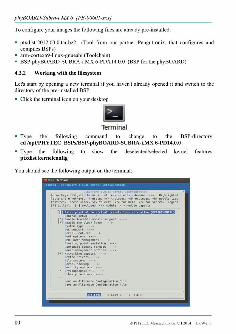
phyBOARD-Subra-i.MX 6 [PB-00601-xxx]
80 © PHYTEC Messtechnik GmbH 2014 L-794e_0
To configure your images the following files are already pre-installed: ptxdist-2012.03.0.tar.bz2 (Tool from our partner Pengutronix, that configures and
compiles BSPs) arm-cortexa9-linux-gnueabi (Toolchain) BSP-phyBOARD-SUBRA-i.MX 6-PDX14.0.0 (BSP for the phyBOARD)
4.3.2 Working with the filesystem
Let's start by opening a new terminal if you haven't already opened it and switch to the directory of the pre-installed BSP: Click the terminal icon on your desktop
Type the following command to change to the BSP-directory: cd /opt/PHYTEC_BSPs/BSP-phyBOARD-SUBRA-i.MX 6-PD14.0.0
Type the following to show the deselected/selected kernel features: ptxdist kernelconfig
You should see the following output on the terminal:
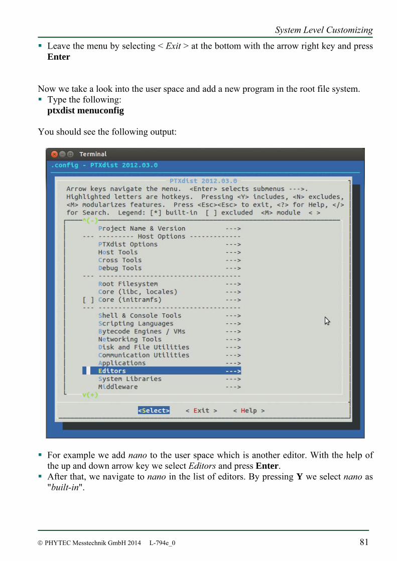
System Level Customizing
© PHYTEC Messtechnik GmbH 2014 L-794e_0 81
Leave the menu by selecting < Exit > at the bottom with the arrow right key and press Enter
Now we take a look into the user space and add a new program in the root file system. Type the following:
ptxdist menuconfig You should see the following output:
For example we add nano to the user space which is another editor. With the help of
the up and down arrow key we select Editors and press Enter. After that, we navigate to nano in the list of editors. By pressing Y we select nano as
"built-in".
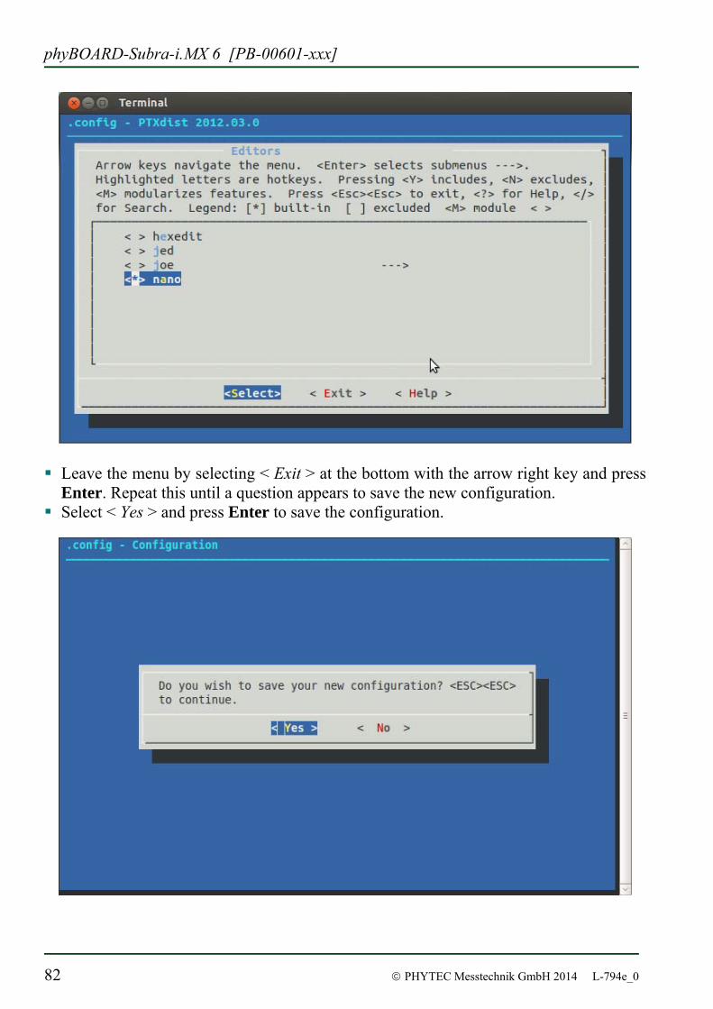
phyBOARD-Subra-i.MX 6 [PB-00601-xxx]
82 © PHYTEC Messtechnik GmbH 2014 L-794e_0
Leave the menu by selecting < Exit > at the bottom with the arrow right key and press
Enter. Repeat this until a question appears to save the new configuration. Select < Yes > and press Enter to save the configuration.
System Level Customizing
© PHYTEC Messtechnik GmbH 2014 L-794e_0 83
Now we can start building the configured BSP. Type :ptxdist go in the terminal window
After it is finished you can finally create the root file system by calling: ptxdist images
You will find the kernel named linuximage and the root file system named root.ubifs in the directory platform- phyBOARD-SUBRA-i.MX 6 /images/.
4.3.3 Writing the Images into the Target’s Flash
In this section you will find a description on how to write the newly created images into the phyBOARD-Subra-i.MX 6’s flash memory. Before the images can be written into the flash, the target will have to download them from a TFTP server which is already pre-installed in our LiveDVD. This will be done from the command line of the boot loader. The images will be copied into the target’s RAM. Then you will have to erase the part of the flash to which you want to copy the images. Finally the images are written from the RAM to the flash. In the default configuration you will find four partitions on the target: The first partition contains the boot loader, the second is used to store the boot loader settings, the third partition stores the Linux kernel, and the fourth contains the root file system.
You should never erase the Barebox partition. If this partition is erased, you won't be able to start your target anymore. In such a case refer to chapter 4.4 “Updating the software”.
Versions of Barebox and Linux kernel must match. Therefore the following steps should only be done using the hardware that was shipped together with the DVD and thus already contains the same version of the BSP.
First open a new terminal window if it is not opened yet. Then change to the directory
/opt/PHYTEC_BSPs/BSP-phyBOARD-SUBRA-i.MX6-PD*
Copy the new images to the /tftpboot directory and exit: cd platform-phyBOARD-Subra-i.MX 6/images sudo cp linuximage /tftpboot sudo cp root.ubifs /tftpboot exit
Open Microcom and press the RESET button on the target. You will see the output "Hit any key to stop autoboot".
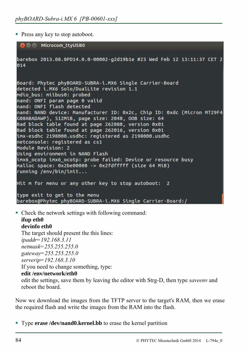
phyBOARD-Subra-i.MX 6 [PB-00601-xxx]
84 © PHYTEC Messtechnik GmbH 2014 L-794e_0
Press any key to stop autoboot.
Check the network settings with following command: ifup eth0 devinfo eth0 The target should present the this lines: ipaddr=192.168.3.11 netmask=255.255.255.0 gateway=255.255.255.0 serverip=192.168.3.10 If you need to change something, type: edit /env/network/eth0 edit the settings, save them by leaving the editor with Strg-D, then type saveenv and reboot the board.
Now we download the images from the TFTP server to the target's RAM, then we erase the required flash and write the images from the RAM into the flash. Type erase /dev/nand0.kernel.bb to erase the kernel partition
System Level Customizing
© PHYTEC Messtechnik GmbH 2014 L-794e_0 85
Type cp /mnt/tftp/linuximage /dev/nand0.kernel.bb to download the kernel using TFTP and write it into the target's flash. The copy process can take up to several minutes
Now we flash the root filesystem type: ubiformat -y /dev/nand0.root ubiattach /dev/nand0.root ubimkvol /dev/ubi0 root 0 cp /mnt/tftp/root.ubifs /dev/ubi0.root
Type boot to boot the phyBOARD-Subra-i.MX 6 with the new kernel and root file system
After the target has successfully finished booting, type root to log in Now we can test our new editor nano by trying to open a file with it nano /etc/profile.environment Close nano by pressing CTRL+X Close Microcom when nano is closed
Troubleshooting: If any problem occurs after writing the kernel or the root file system into the flash memory, you can restore the original kernel (linuximage) and root file system (root.ubifs) from the /tftpboot directory.
In this section you learned how to download images from a tftp server into the RAM of the target. The images have been written from RAM to flash and finally the target was started with the new images.
All files are also downloadable from our ftp server or you can find them on our Linux-phyBOARD-Subra-i.MX 6-Kit-DVD under /PHYTEC/BSP/. If you want other versions check our ftp server too: ftp://ftp.phytec.de/pub/Products/
phyBOARD-Subra-i.MX 6 [PB-00601-xxx]
86 © PHYTEC Messtechnik GmbH 2014 L-794e_0
4.4 Updating the software
If you found a newer BSP on our ftp server ftp://ftp.phytec.de/pub/Products and want to flash it, this chapter shows how to do. Also in case that your phyBOARD-Subra-i.MX 6 doesn’t start anymore because you damaged its software during the previous chapter, you’re right here, too. In the latter case you’ll find all needed original images on the DVD under /PHYTEC/BSP.
The phyBOARD-Subra-i.MX 6 is configured to boot only from NAND!In order to be able to boot from SD card, switches S3_1 and S3_2 of the Boot Selection Switch S3 must be ON. If S3 is not available on your board you need to close solder jumpers R4 and R5!
4.4.1 Creating a bootable SD card
In case that your phyBOARD-Subra-i.MX 6 doesn’t start anymore due to a damaged bootloader, you need to boot from an SD card. This SD card must be formatted in a special way, because the i.MX 6 doesn’t know anything about file systems. Instead the expected location of the bootloader within a reserved 8 MB space at the beginning of the SD card is hard coded. Type ls /dev on your Ubuntu PC Insert an SD card into the card reader slot of your Ubuntu PC. Type ls /dev again. You should now see one more /dev/sd<x> device and at least one
additional /dev/sd<x><n> device. For each newly appeared /dev/sd<x><n> device type umount /dev/sd<x><n> Type sudo fdisk /dev/sd<x>. Be very careful that you type the right letter for <x>!
You are able to destroy the content of your whole hard disk or of any other attached mass storage device in case that you typed the wrong letter at this point!
Type u and ENTER in order to use sectors as scale unit of all further specifications Type p and ENTER for getting SD card’s parameter Look for the sector size. It should be 512 bytes. Then calculate the amount of sectors
needed for 8 MB space: 8192 * (1024 / sectorsize). Also calculate the amount of sectors needed for 256 MB space: 262144 * (1024 / sectorsize)
Type d and ENTER for deleting the first partition of the SD card. If there are more partitions, please delete them also
Use the first 256 MB of the SD card for creating a new first partition. Reserve 8 MB space at its' beginning. Thus type n ENTER p ENTER 1 ENTER. You will now get a default value presented for the first sector. Add the calculated amount of sectors necessary for 8 MB space to it and type in the result followed by ENTER. Finally subtract 1 from the amount of sectors necessary for 256 MB space and type in the result followed by ENTER
System Level Customizing
© PHYTEC Messtechnik GmbH 2014 L-794e_0 87
Use the remaining space of the SD card for creating a new second partition. Type n ENTER p ENTER 2 ENTER. Now type in the amount of sectors needed for 256 MB space followed by ENTER. Finally accept the default value for the last sector by just typing ENTER again
Declare the first partition as FAT by typing t ENTER 1 ENTER c ENTER Save your work and leave fdisk by typing w and ENTER Type sudo mkfs.vfat /dev/sd<x>1 Type sudo mkfs.ext3 /dev/sd<x>2 Type sync
The card is now ready for writing a Barebox image to the reserved 8 MB space. Type sudo dd if=./barebox-phytec-pbab05s-512mb.img of=/dev/sd<x> bs=512 skip=2
seek=2 Type sync
Copy the images of Barebox, Linux kernel (linuximage) and rootfs (root.ubifs) to the first partition of the SD card. Extract the archive of the rootfs to the second partition: Type sudo tar -xvzf ./root.tgz -C /media/<path_of_SD_card> Type sync
The SD card should now allow you to boot up to the Linux prompt again.
4.4.2 Flashing the Bootloader
Use bootable SD card in order to boot into Barebox.
The phyBOARD-Subra-i.MX 6 is configured to boot only from NAND!In order to be able to boot from SD card, switches S3_1 and S3_2 of the Boot Selection Switch S3 must be ON. If S3 is not available on your board you need to close solder jumpers R4 and R5!
Type barebox_update -t nand /mnt/mmc/barebox-phytec-pbab05s-512mb.img
phyBOARD-Subra-i.MX 6 [PB-00601-xxx]
88 © PHYTEC Messtechnik GmbH 2014 L-794e_0
Alternatively you could use bootable SD card in order to boot into Linux. Then copy Barebox’s image from your PC into the rootfs of your module for example by using an ftp-connection. After that flash the image into the NAND by typing: kobs-ng init --chip_0_device_path=/dev/mtd0 -v -w barebox-image In case you use a module with an SPI NOR (not included by default), you need to write to /dev/mtd4 instead to /dev/mtd0.
4.4.3 Writing the Kernel and Root File System into Flash
Use a bootable SD card in order to boot into Barebox. Flash the Linux kernel by typing
erase /dev/nand0.kernel.bb cp /mnt/mmc/linuximage /dev/nand0.kernel.bb
Write root file system into flash by typing
ubiformat /dev/nand0.root ubiattach /dev/nand0.root ubimkvol /dev/ubi0 root 0 cp /mnt/mmc/root.ubifs /dev/ubi0.root
Troubleshooting: In some rare cases it might be that using these UBI commands will not lead to a working root file system. Then it should help to replace root.ubifs by root.ubi on your SD card and use the following commands: erase /dev/nand0.root.bb cp /mnt/mmc/root.ubi /dev/nand0.root.bb But note that normally you should not flash Linux’s root file system into NAND by this way! Ubifs keeps erase counters within the NAND in order to be able to balance write cycles equally over all NAND sectors. So if there is already an ubifs on your module and you want to replace it by a new one, using erase and cp will also erase these erase counters, and this “brute way” should be avoided.
System Level Customizing
© PHYTEC Messtechnik GmbH 2014 L-794e_0 89
4.5 Setup your own Linux-Host-PC
This chapter is for developers who want to use their own existing environment and not our modified Ubuntu version. It is not needed if you have already installed our modified Ubuntu version as explained in the Application Guide. We give an overview in this chapter of the modifications which we made to the Ubuntu version on the phyBOARD-Subra-i.MX 6 LiveDVD in comparison to the original Ubuntu. In the following we distinguish between optional and essential modifications. So you can see faster which changes are important to execute this Application Guide in case you don't want to use our modified Ubuntu version. You can find a step-by-step instruction of the essential changes in order to modify your own distribution.
We can't guarantee that the presented changes are compatible to other distributions or versions. If you want to use another distribution, it might take a lot of individual initiative. We do not support other distributions. You should be sure about what you do.
4.5.1 Essential settings
In the following you see a short instruction of the important settings which are essential to guarantee the execution of the examples in this Application Guide. 4.5.1.1 Installation of software packages
At first various software packages required must be installed using the package manager APT. To gain a better understanding of the packages required they are installed separately according to their function: 1. Packages which are needed for compiling and building the Board Support Package:
sudo apt-get -y install libncurses-dev gawk flex bison texinfo gettext 2. Packages for developoment
sudo apt-get -y install vim eclipse 3. Packeges to set up the TFTP server:
sudo apt-get -y install tftpd-hpa During installation it can happen that some programs ask for a license agreement. Just go through the steps. The first preparations are completed. In the next sections you will proceed with the installation of Eclipse and the set up of the TFTP server.
phyBOARD-Subra-i.MX 6 [PB-00601-xxx]
90 © PHYTEC Messtechnik GmbH 2014 L-794e_0
4.5.1.2 Setting up Eclipse and integrate plug ins
The instructions in this chapter show how to setup Eclipse and integrate the plug ins for QT and C/C++. Thereby you can assign own programs, written in Eclipse, to the target. First you must create a workspace folder, in which you can save your Eclipse projects.
In the example this is done in your /home/ folder: mkdir /home/$USER/workspace
Thereafter you can open Eclipse and insert the path to the created workspace in the pop-up window: eclipse
Eclipse is started and now we click at Help in the menu bar Install new Software. Thereupon a window was opened and in the text field "Work with" we enter the
following address: http://download.eclipse.org/tools/cdt/releases/indigo and click on Add.
After a while the software which we can integrate appears in the area with a scrollbar. We check "CDT Main Features" and click on Next.
Now the system shows us an overview of the installation details, which we skip with a click on Next.
At last the system shows us the licensing agreement, which we accept and after we have clicked on Finish it begins to install the required software.
The CDT plug in is installed. We close Eclipse and go on with the QT integration. For the QT integration you must use an external package from the Nokia website.
This package is already available on our DVD under /PHYTEC/Applications. Unpack the compressed archive in the /usr/lib folder: cd /usr/lib tar xzf ...PHYTEC/Applications/qt-eclipse-integration-linux.x86-1.6.1.tar.gz
After that start Eclipse with the option clean, which cleans any cached data: eclipse --clean
Eclipse is started and now you must include two path variables: In the menu bar click on Window ► Preferences ► QT and enter the following QT specific information Name: QT ► Bin Path: /opt/PHYTEC_BSPs/BSP-phyBOARD-SUBRA-i.MX6-PD14.0.0/platform-phyBOARD-SUBRA-i.MX6/sysroot-cross/bin ► Include Path: /opt/PHYTEC_BSPs/BSP-phyBOARD-SUBRA-i.MX6-PD14.0.0/platform-phyBOARD-SUBRA-i.MX6/sysroot-target/usr/include
Finally close Eclipse and start it again with the clean option.
Congratulations! You have successfully integrated two new plugins in Eclipse and now you can start programming in C/C++ and QT in an Eclipse environment. In the next sub-section you will find a short introduction on how to setup a TFTP server.
System Level Customizing
© PHYTEC Messtechnik GmbH 2014 L-794e_0 91
4.5.1.3 Setting up a TFTP server
In the chapter "Installation of software packages" you have installed the required packages to set up a TFTP server. Now we must change some short settings.
First change the file /etc/default/tftp-hpa as follows: TFTP_USERNAME="tftp" TFTP_DIRECTORY="/tftpboot" TFTP_ADDRESS="0.0.0.0:69" TFTP_OPTIONS="--secure"
Then create a folder called /tftpboot. The TFTP server will access this folder later. mkdir /tftpboot
At last we must set the right permissions: chmod 777 /tftpboot
You have successfully set up the TFT server. In the future the phyBOARD-Subra-i.MX 6 can access to the /tftpboot/ folder to load the images.
4.5.2 Optional settings
In the following we show the optional settings. These settings are not needed for a successful operation of this Application Guide. They only simplify the handling and the look of the system. For this reason we show the modifications without big explanation. Installation of vim, the improved vi editor. Creation of desktop-icons for faster and easier start of required programs. History-search-backward and history-search-forward in /etc/inputrc is activated.
This allows you to search through your history with the entered string. Also there are some scripts that will be executed at the first start after the
installation. These scripts ensure that the right permissions are set for the created user.
Congratulations! You have successfully configured your Ubuntu to work with.
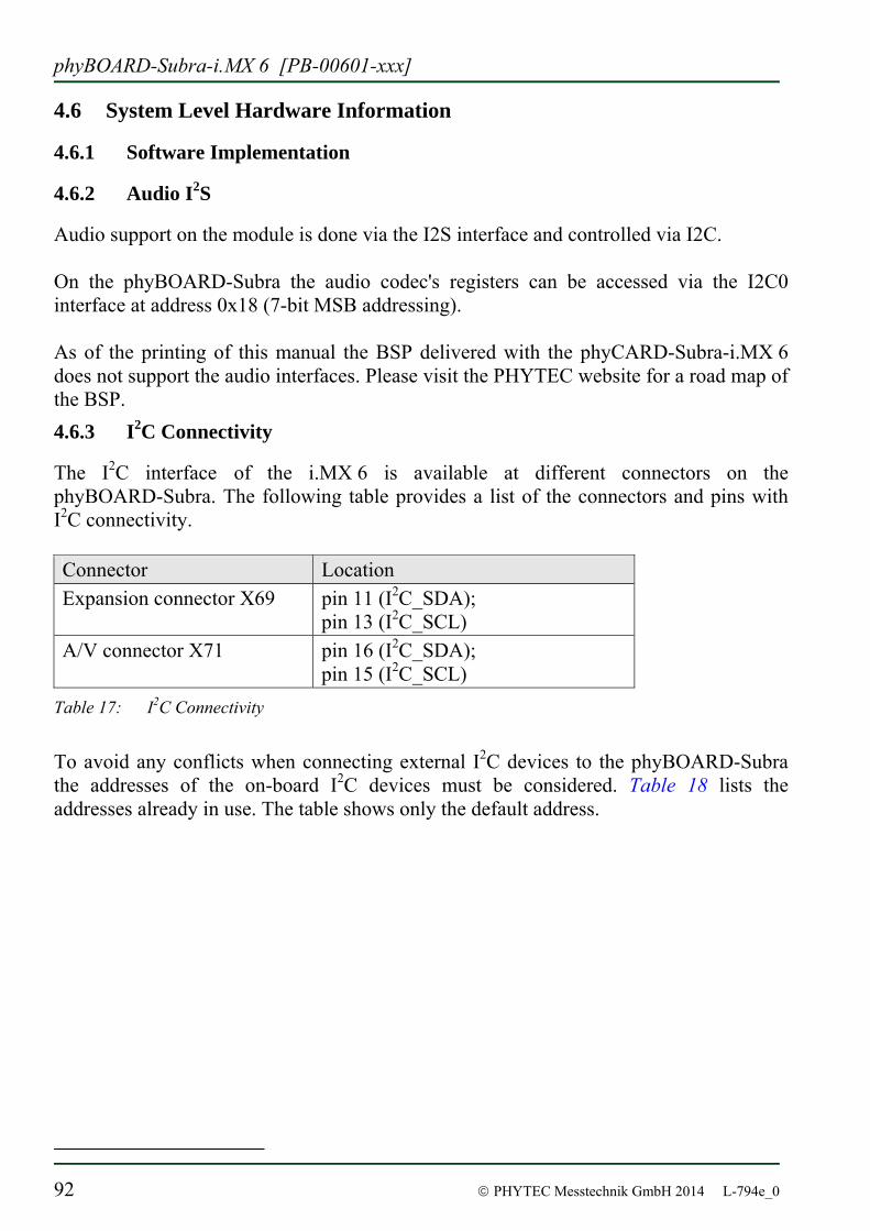
phyBOARD-Subra-i.MX 6 [PB-00601-xxx]
92 © PHYTEC Messtechnik GmbH 2014 L-794e_0
4.6 System Level Hardware Information
4.6.1 Software Implementation
4.6.2 Audio I2S
Audio support on the module is done via the I2S interface and controlled via I2C. On the phyBOARD-Subra the audio codec's registers can be accessed via the I2C0 interface at address 0x18 (7-bit MSB addressing). As of the printing of this manual the BSP delivered with the phyCARD-Subra-i.MX 6 does not support the audio interfaces. Please visit the PHYTEC website for a road map of the BSP. 4.6.3 I2C Connectivity
The I2C interface of the i.MX 6 is available at different connectors on the phyBOARD-Subra. The following table provides a list of the connectors and pins with I2C connectivity. Connector Location Expansion connector X69 pin 11 (I2C_SDA);
pin 13 (I2C_SCL) A/V connector X71 pin 16 (I2C_SDA);
pin 15 (I2C_SCL) Table 17: I2C Connectivity
To avoid any conflicts when connecting external I2C devices to the phyBOARD-Subra the addresses of the on-board I2C devices must be considered. Table 18 lists the addresses already in use. The table shows only the default address.
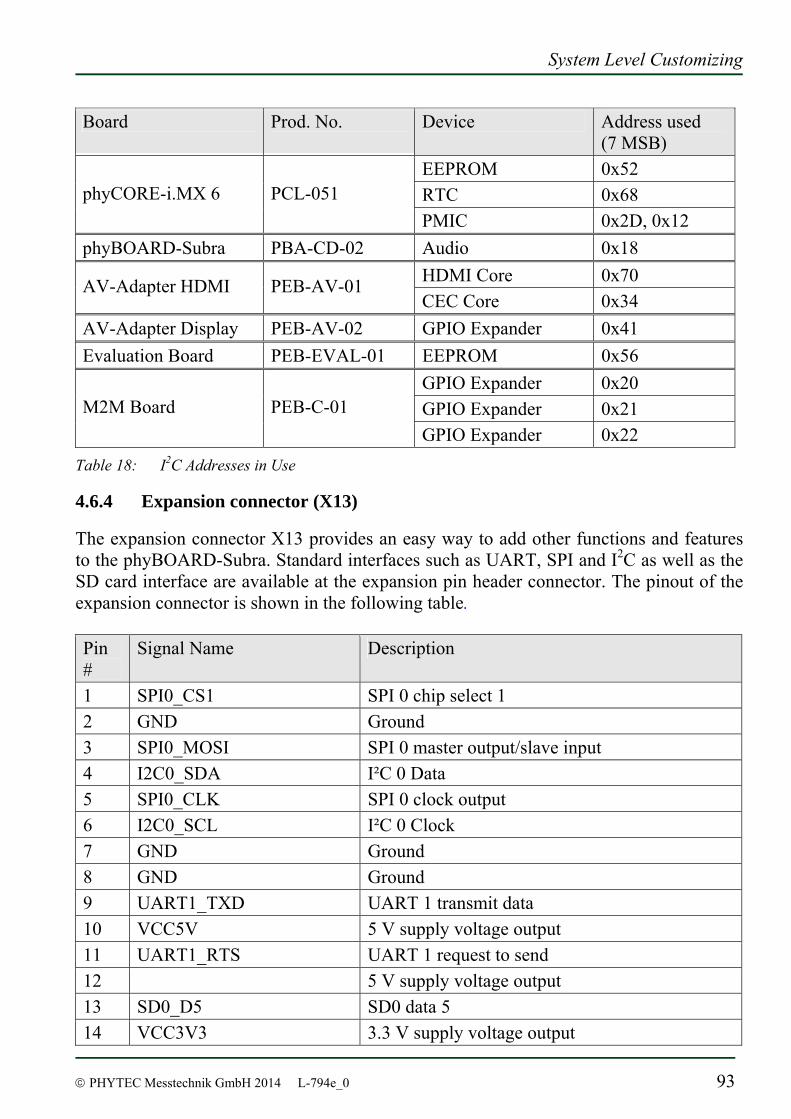
System Level Customizing
© PHYTEC Messtechnik GmbH 2014 L-794e_0 93
Board Prod. No. Device Address used (7 MSB)
EEPROM 0x52 RTC 0x68 phyCORE-i.MX 6 PCL-051 PMIC 0x2D, 0x12
phyBOARD-Subra PBA-CD-02 Audio 0x18 HDMI Core 0x70 AV-Adapter HDMI PEB-AV-01 CEC Core 0x34
AV-Adapter Display PEB-AV-02 GPIO Expander 0x41 Evaluation Board PEB-EVAL-01 EEPROM 0x56
GPIO Expander 0x20 GPIO Expander 0x21 M2M Board PEB-C-01 GPIO Expander 0x22
Table 18: I2C Addresses in Use
4.6.4 Expansion connector (X13)
The expansion connector X13 provides an easy way to add other functions and features to the phyBOARD-Subra. Standard interfaces such as UART, SPI and I2C as well as the SD card interface are available at the expansion pin header connector. The pinout of the expansion connector is shown in the following table. Pin #
Signal Name Description
1 SPI0_CS1 SPI 0 chip select 1 2 GND Ground 3 SPI0_MOSI SPI 0 master output/slave input 4 I2C0_SDA I²C 0 Data 5 SPI0_CLK SPI 0 clock output 6 I2C0_SCL I²C 0 Clock 7 GND Ground 8 GND Ground 9 UART1_TXD UART 1 transmit data 10 VCC5V 5 V supply voltage output 11 UART1_RTS UART 1 request to send 12 5 V supply voltage output 13 SD0_D5 SD0 data 5 14 VCC3V3 3.3 V supply voltage output
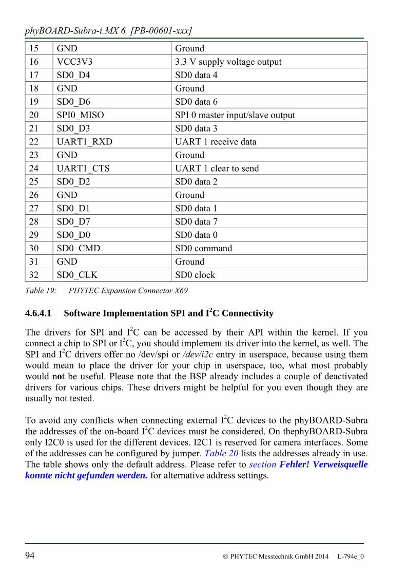
phyBOARD-Subra-i.MX 6 [PB-00601-xxx]
94 © PHYTEC Messtechnik GmbH 2014 L-794e_0
15 GND Ground 16 VCC3V3 3.3 V supply voltage output 17 SD0_D4 SD0 data 4 18 GND Ground 19 SD0_D6 SD0 data 6 20 SPI0_MISO SPI 0 master input/slave output 21 SD0_D3 SD0 data 3 22 UART1_RXD UART 1 receive data 23 GND Ground 24 UART1_CTS UART 1 clear to send 25 SD0_D2 SD0 data 2 26 GND Ground 27 SD0_D1 SD0 data 1 28 SD0_D7 SD0 data 7 29 SD0_D0 SD0 data 0 30 SD0_CMD SD0 command 31 GND Ground 32 SD0_CLK SD0 clock
Table 19: PHYTEC Expansion Connector X69
4.6.4.1 Software Implementation SPI and I2C Connectivity
The drivers for SPI and I2C can be accessed by their API within the kernel. If you connect a chip to SPI or I2C, you should implement its driver into the kernel, as well. The SPI and I2C drivers offer no /dev/spi or /dev/i2c entry in userspace, because using them would mean to place the driver for your chip in userspace, too, what most probably would not be useful. Please note that the BSP already includes a couple of deactivated drivers for various chips. These drivers might be helpful for you even though they are usually not tested. To avoid any conflicts when connecting external I2C devices to the phyBOARD-Subra the addresses of the on-board I2C devices must be considered. On thephyBOARD-Subra only I2C0 is used for the different devices. I2C1 is reserved for camera interfaces. Some of the addresses can be configured by jumper. Table 20 lists the addresses already in use. The table shows only the default address. Please refer to section Fehler! Verweisquelle konnte nicht gefunden werden. for alternative address settings.
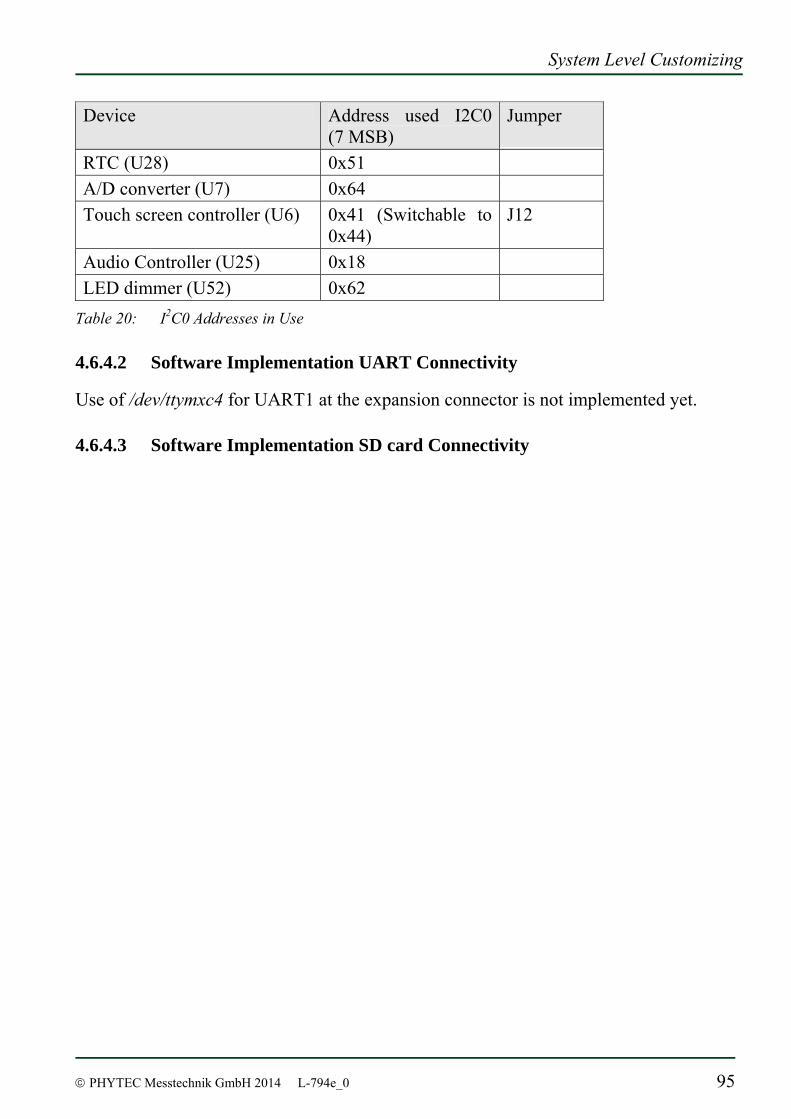
System Level Customizing
© PHYTEC Messtechnik GmbH 2014 L-794e_0 95
Device Address used I2C0 (7 MSB)
Jumper
RTC (U28) 0x51 A/D converter (U7) 0x64 Touch screen controller (U6) 0x41 (Switchable to
0x44) J12
Audio Controller (U25) 0x18 LED dimmer (U52) 0x62
Table 20: I2C0 Addresses in Use
4.6.4.2 Software Implementation UART Connectivity
Use of /dev/ttymxc4 for UART1 at the expansion connector is not implemented yet.
4.6.4.3 Software Implementation SD card Connectivity
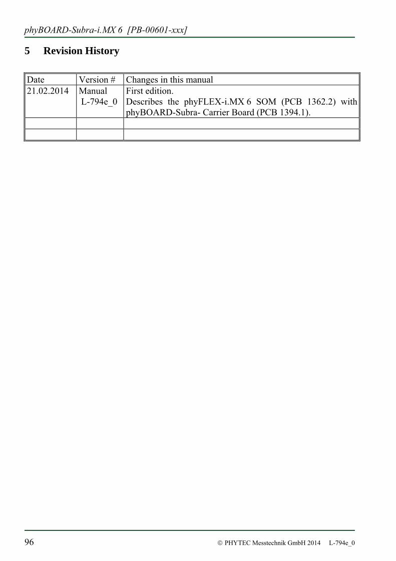
phyBOARD-Subra-i.MX 6 [PB-00601-xxx]
96 © PHYTEC Messtechnik GmbH 2014 L-794e_0
5 Revision History
Date Version # Changes in this manual 21.02.2014 Manual
L-794e_0
First edition. Describes the phyFLEX-i.MX 6 SOM (PCB 1362.2) with phyBOARD-Subra- Carrier Board (PCB 1394.1).
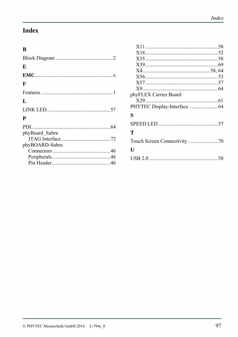
Index
© PHYTEC Messtechnik GmbH 2014 L-794e_0 97
Index
B Block Diagram ............................................2
E EMC............................................................x
F Features .......................................................1
L LINK LED.................................................57
P PDI.............................................................64 phyBoard_Subra
JTAG Interface......................................72 phyBOARD-Subra
Connectors ............................................46 Peripherals.............................................46 Pin Header.............................................46
X11........................................................58 X18........................................................52 X35........................................................58 X39........................................................69 X4....................................................58, 64 X56........................................................53 X57........................................................57 X9..........................................................64
phyFLEX Carrier Board X29........................................................61
PHYTEC Display-Interface ......................64
S SPEED LED..............................................57
T Touch Screen Connectivity .......................70
U USB 2.0 .....................................................58

phyBOARD-Subra-i.MX 6 [PB-00601-xxx]
98 © PHYTEC Messtechnik GmbH 2014 L-794e_0

Suggestions for Improvement
© PHYTEC MesstechnikGmbH 2013 L-792e_0
Document: phyBOARD-Subra-i.MX 6 Document number: L-794e_0, February 2013 How would you improve this manual? Did you find any mistakes in this manual? page Submitted by: Customer number: Name: Company: Address: Return to: PHYTEC Messtechnik GmbH Postfach 100403 D-55135 Mainz, Germany Fax : +49 (6131) 9221-33

Published by
© PHYTEC Messtechnik GmbH 2014 Ordering No. L-794e_0
Printed in Germany

101


![phyCORE -TC399 Hardware Manual - Phytec 2015...phyCORE ®-TC399[KSP-0200-0.A0] iv PHYTEC Messtechnik GmbH 2018 L-853e.A0 Conventions, Abbreviations and Acronyms This hardware manual](https://img.pdfslide.us/doc/110x75/5eca146a461a334655520675/phycore-tc399-hardware-manual-phytec-2015-phycore-tc399ksp-0200-0a0.jpg)