Embed Size (px)
Citation preview
1
Photopia™ for SOLIDWORKS® Tutorial 3 – PODT Lens Design
OVERVIEW
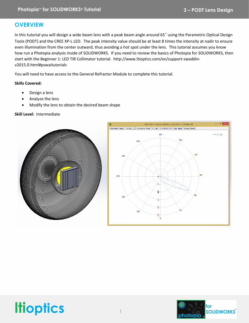
In this tutorial you will design a wide beam lens with a peak beam angle around 65° using the Parametric Optical Design
Tools (PODT) and the CREE XP-L LED. The peak intensity value should be at least 8 times the intensity at nadir to ensure
even illumination from the center outward, thus avoiding a hot spot under the lens. This tutorial assumes you know
how run a Photopia analysis inside of SOLIDWORKS. If you need to review the basics of Photopia for SOLIDWORKS, then
start with the Beginner 1: LED TIR Collimator tutorial. http://www.ltioptics.com/en/support-swaddin-
v2015.0.html#pswaitutorials
You will need to have access to the General Refractor Module to complete this tutorial.
Skills Covered:
Design a lens
Analyze the lens
Modify the lens to obtain the desired beam shape
Skill Level: Intermediate
2
Photopia™ for SOLIDWORKS® Tutorial 3 – PODT Lens Design
1. Start a New Part
Start SOLIDWORKS and click File > New and choose a Part. Set the units for the part to be MMGS.
2. Start a Sketch and Define Constraints
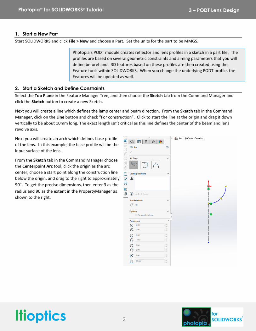
Select the Top Plane in the Feature Manager Tree, and then choose the Sketch tab from the Command Manager and
click the Sketch button to create a new Sketch.
Next you will create a line which defines the lamp center and beam direction. From the Sketch tab in the Command
Manager, click on the Line button and check “For construction”. Click to start the line at the origin and drag it down
vertically to be about 10mm long. The exact length isn’t critical as this line defines the center of the beam and lens
revolve axis.
Next you will create an arch which defines base profile
of the lens. In this example, the base profile will be the
input surface of the lens.
From the Sketch tab in the Command Manager choose
the Centerpoint Arc tool, click the origin as the arc
center, choose a start point along the construction line
below the origin, and drag to the right to approximately
90°. To get the precise dimensions, then enter 3 as the
radius and 90 as the extent in the PropertyManager as
shown to the right.
Photopia’s PODT module creates reflector and lens profiles in a sketch in a part file. The
profiles are based on several geometric constraints and aiming parameters that you will
define beforehand. 3D features based on these profiles are then created using the
Feature tools within SOLIDWORKS. When you change the underlying PODT profile, the
Features will be updated as well.
3
Photopia™ for SOLIDWORKS® Tutorial 3 – PODT Lens Design
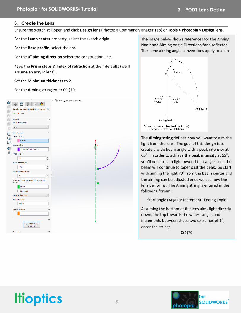
3. Create the Lens
Ensure the sketch still open and click Design lens (Photopia CommandManager Tab) or Tools > Photopia > Design lens.
For the Lamp center property, select the sketch origin.
For the Base profile, select the arc.
For the 0° aiming direction select the construction line.
Keep the Prism steps & Index of refraction at their defaults (we’ll
assume an acrylic lens).
Set the Minimum thickness to 2.
For the Aiming string enter 0(1)70
The image below shows references for the Aiming
Nadir and Aiming Angle Directions for a reflector.
The same aiming angle conventions apply to a lens.
The Aiming string defines how you want to aim the
light from the lens. The goal of this design is to
create a wide beam angle with a peak intensity at
65°. In order to achieve the peak intensity at 65°,
you’ll need to aim light beyond that angle since the
beam will continue to taper past the peak. So start
with aiming the light 70° from the beam center and
the aiming can be adjusted once we see how the
lens performs. The Aiming string is entered in the
following format:
Start angle (Angular Increment) Ending angle
Assuming the bottom of the lens aims light directly
down, the top towards the widest angle, and
increments between those two extremes of 1°,
enter the string:
0(1)70
4
Photopia™ for SOLIDWORKS® Tutorial 3 – PODT Lens Design
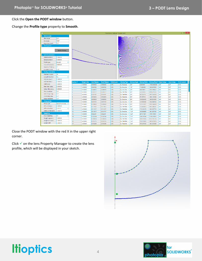
Click the Open the PODT window button.
Change the Profile type property to Smooth.
Close the PODT window with the red X in the upper right
corner.
Click on the lens Property Manager to create the lens
profile, which will be displayed in your sketch.
5
Photopia™ for SOLIDWORKS® Tutorial 3 – PODT Lens Design
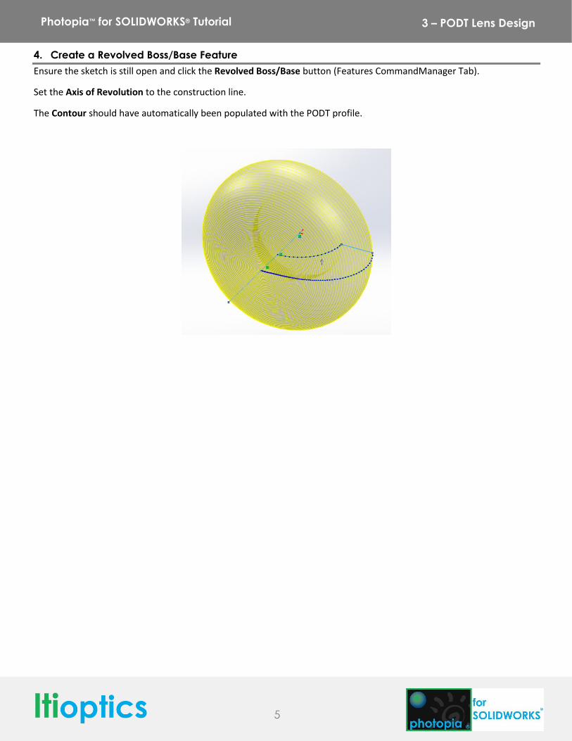
4. Create a Revolved Boss/Base Feature
Ensure the sketch is still open and click the Revolved Boss/Base button (Features CommandManager Tab).
Set the Axis of Revolution to the construction line.
The Contour should have automatically been populated with the PODT profile.
6
Photopia™ for SOLIDWORKS® Tutorial 3 – PODT Lens Design
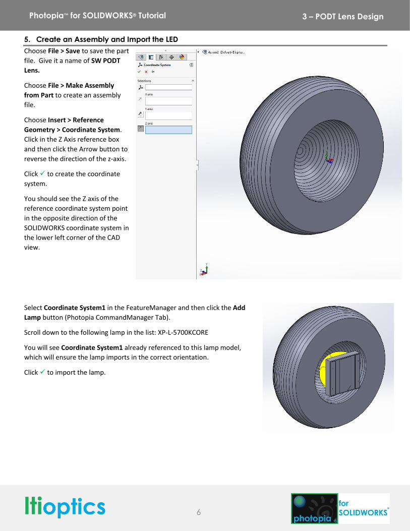
5. Create an Assembly and Import the LED
Choose File > Save to save the part
file. Give it a name of SW PODT
Lens.
Choose File > Make Assembly
from Part to create an assembly
file.
Choose Insert > Reference
Geometry > Coordinate System.
Click in the Z Axis reference box
and then click the Arrow button to
reverse the direction of the z-axis.
Click to create the coordinate
system.
You should see the Z axis of the
reference coordinate system point
in the opposite direction of the
SOLIDWORKS coordinate system in
the lower left corner of the CAD
view.
Select Coordinate System1 in the FeatureManager and then click the Add
Lamp button (Photopia CommandManager Tab).
Scroll down to the following lamp in the list: XP-L-5700KCORE
You will see Coordinate System1 already referenced to this lamp model,
which will ensure the lamp imports in the correct orientation.
Click to import the lamp.
7
Photopia™ for SOLIDWORKS® Tutorial 3 – PODT Lens Design
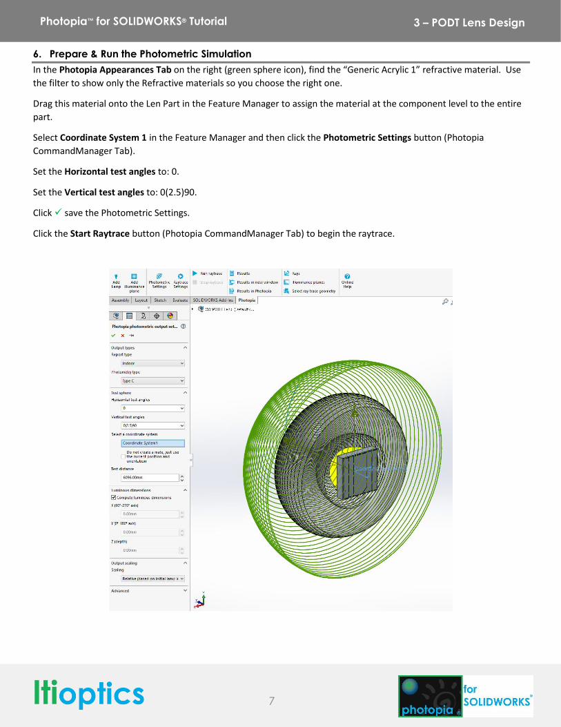
6. Prepare & Run the Photometric Simulation
In the Photopia Appearances Tab on the right (green sphere icon), find the “Generic Acrylic 1” refractive material. Use
the filter to show only the Refractive materials so you choose the right one.
Drag this material onto the Len Part in the Feature Manager to assign the material at the component level to the entire
part.
Select Coordinate System 1 in the Feature Manager and then click the Photometric Settings button (Photopia
CommandManager Tab).
Set the Horizontal test angles to: 0.
Set the Vertical test angles to: 0(2.5)90.
Click save the Photometric Settings.
Click the Start Raytrace button (Photopia CommandManager Tab) to begin the raytrace.
8
Photopia™ for SOLIDWORKS® Tutorial 3 – PODT Lens Design
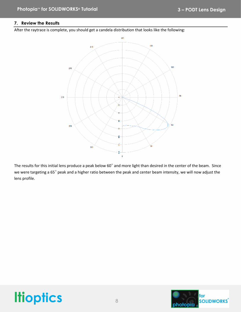
7. Review the Results
After the raytrace is complete, you should get a candela distribution that looks like the following:
The results for this initial lens produce a peak below 60° and more light than desired in the center of the beam. Since
we were targeting a 65° peak and a higher ratio between the peak and center beam intensity, we will now adjust the
lens profile.
9
Photopia™ for SOLIDWORKS® Tutorial 3 – PODT Lens Design
8. Modifying the Lens
Right click on the SW PODT Lens in the Feature Manager and select Edit Part from the flyout menu.
Select the Revolve1 feature and then click the Design lens button (Photopia CommandManager Tab).
Under Reload Lens, click the drop down list and choose the
last item in the list. This will associate your initial lens
parameters with the revolved boss/base feature.
Click the Open PODT window button.
Set the Number of Prism Steps to 100. This will create a
smoother lens profile.
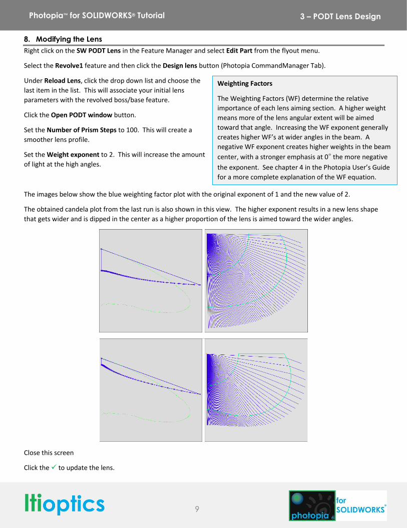
Set the Weight exponent to 2. This will increase the amount
of light at the high angles.
The images below show the blue weighting factor plot with the original exponent of 1 and the new value of 2.
The obtained candela plot from the last run is also shown in this view. The higher exponent results in a new lens shape
that gets wider and is dipped in the center as a higher proportion of the lens is aimed toward the wider angles.
Close this screen
Click the to update the lens.
Weighting Factors
The Weighting Factors (WF) determine the relative
importance of each lens aiming section. A higher weight
means more of the lens angular extent will be aimed
toward that angle. Increasing the WF exponent generally
creates higher WF’s at wider angles in the beam. A
negative WF exponent creates higher weights in the beam
center, with a stronger emphasis at 0° the more negative
the exponent. See chapter 4 in the Photopia User’s Guide
for a more complete explanation of the WF equation.
10
Photopia™ for SOLIDWORKS® Tutorial 3 – PODT Lens Design
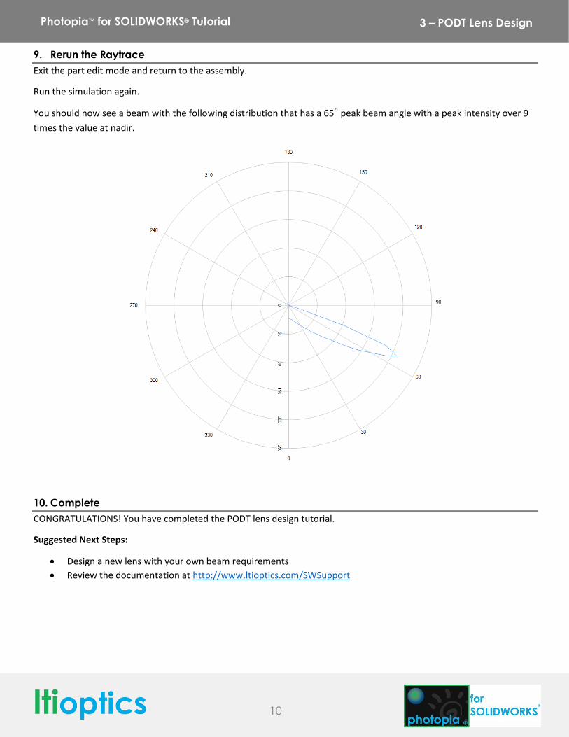
9. Rerun the Raytrace
Exit the part edit mode and return to the assembly.
Run the simulation again.
You should now see a beam with the following distribution that has a 65° peak beam angle with a peak intensity over 9
times the value at nadir.
10. Complete
CONGRATULATIONS! You have completed the PODT lens design tutorial.
Suggested Next Steps:
Design a new lens with your own beam requirements
Review the documentation at http://www.ltioptics.com/SWSupport