Embed Size (px)
Citation preview
Photonic Integration and UsageGuidelines Manual
D-18228
by
George Lutes
with assistance from
Meirong Tu
1999NASA Electronics Packaging Program (NEPP)
September 27, 1999
i
Contents
1. Introduction ii
2. Photonic Systems with Potential Space Applications 1
3. Fiber Optic Reference Signal Distribution and Cable StabilizerImplemented in SRTM 9
4. Safe Use of the UTP Fiber Optic Transmitter to be Used on SRTM 10
5. Radiation Darkening of the SRTM Optical Fiber 18
6. Development of Fiber Optic Cable Assemblies for Space Applications 20
7. A Comparison of Gore-Tex 0.190” Diameter Coaxial Cable to Fiber Optic Cable 22
8. New Low Profile Connectors (MT-RJ, LC, VF-45) 29
9. Some Typical Fiber Optic Connector Parameters 32
10. Photonic Components 34
11. Photonic Component and System Manufacturers 41
12. References 58
ii
1.0 Introduction
Photonic technology is developing in much the same way that semiconductor technology developed. Thefirst electronic semiconductor devices that came to market were discrete devices that had to be assembledinto functions and systems by connecting them together with wire and solder. As the material andfabrication technologies became more sophisticated the manufacturers began to combine functions onto asingle substrate. The interconnections were fabricated right on the board with the devices. These werecalled integrated circuits.
The first electrical integrated circuits were digital functions because they were easier to fabricate. Thencame analog functions such as the operational amplifier. For many years digital circuits and analogcircuits were not fabricated in the same integrated circuit. This was because of difficulties involved indoing so. Eventually those difficulties were overcome and combined analog and digital integrated circuitswere produced.
Over the years integrated electronic circuits have become increasingly sophisticated and device counts ona single substrate have approached a million devices.
Photonic technology is still, for the most part, in the discrete device stage of development. A few simpleintegrated optical circuits (IOCs) have been developed but the level of sophistication is in its infancy.Most of today’s photonic assemblies and systems are still assembled from discrete photonic devices whichare connected together with optical fibers or free-space light beams.
The technology for making reliable connections between discrete photonic devices is still often unreliableand almost always labor intensive and therefore costly. This has limited the use of photonic system toapplications where the benefits were so overriding that the cost is of no consequence. This has left manyapplications begging for the benefits of photonics but held back by the cost.
There is a tendency for industry to neglect the current problems with interconnections between discretephotonic devices in its quest for IOCs which will eventually mitigate these problems by making theseconnections on the chip level. To neglect today’s problems while waiting for the development of IOCswould not be wise for the photonics industry for it will delay the infusion of photonic technology intosystems such as synthetic aperture radar which can be greatly improved by its use now.
As the problems with interconnects between discrete photonic components are resolved the reliability willimprove and the price will come down. This will entice more manufacturers to take advantage of thebenefits of photonic technology and incorporate it into their systems. This will lead to more competitionwhich will in turn increase the demand for more sophisticated photonic assemblies with reducedquantities of discrete devices and more IOCs.
Eventually IOCs will become as sophisticated as their electronic counterparts are today. Many reliabilityissues will surface as they are developed.
The reliability issues of discrete photonic devices must be addressed now because NASA projects needphotonic systems they can use now. They cannot wait for IOCs to be developed before taking advantage ofphotonic technology. The benefits are too great. At the same time we must begin to plan for resolving thereliability issues related to IOCs as they move out of the laboratory.
This manual will point out some of the advantages of using photonic technology. It will give someexamples of photonic systems that have potential space applications. It will explain why these systemswork well when implemented in photonics and why the performance cannot be duplicated whenimplemented in copper based radio frequency systems. There is a description of one of these systems that
iii
was implemented in the Shuttle Radar Topographic Mapper (SRTM). There is an analysis on the safety ofthe laser transmitter used on SRTM.
There is a section on fiber optic cables and connectors. It includes the analysis showing why no shieldingin additional to the jacket would be needed on optical fiber used in SRTM. There is an overview of fiberoptic connector and cable assemblies and a comparison of fiber optic cable versus the best availablecoaxial cable that was small enough to fit in the SRTM mast. The newly introduced low profile fiber opticconnectors are described and some typical performance data is given on traditional fiber optic connectors.
Finally there is a list of some of the better known photonic parts and device manufacturers with theiraddresses and phone numbers and a list of some of the components they manufacture. The manual endswith a list of references related to implementation of photonic systems.
1
2.0 Photonic Systems with Potential Space Applications
The block diagrams shown in this section are a few examples of analog photonic systems that havepotential for space applications.
The cable stabilizer and reference signal distribution system is used on SRTM. It could not have beenimplemented in a metallic transmission line and achieved the stability that was achieved with the photonicsystem using optical fiber.
2
ISOLATOROPTICAL
LASER
OPTICAL
SPLITTE
OPTICAL
RECEIVER
OPTICALOUTPUT
FREQUENCYREFERENCEINPUT
RF
TORECEIVERS
RF
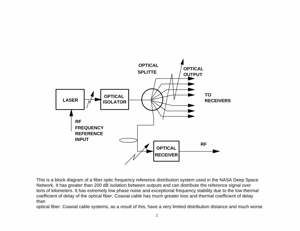
This is a block diagram of a fiber optic frequency reference distribution system used in the NASA Deep SpaceNetwork. It has greater than 200 dB isolation between outputs and can distribute the reference signal overtens of kilometers. It has extremely low phase noise and exceptional frequency stability due to the low thermalcoefficient of delay of the optical fiber. Coaxial cable has much greater loss and thermal coefficient of delaythanoptical fiber. Coaxial cable systems, as a result of this, have a very limited distribution distance and much worsefrequency stability than a fiber optic distribution system.
3
LASEROPTICAL
MODULATOR
OPTICALCOUPLE
R
PHOTO-DETECTO
R
SIGNALOUTPU
T
SIGNAL
INPUTDIGITAL
CONTROL
0
1 2 4 8
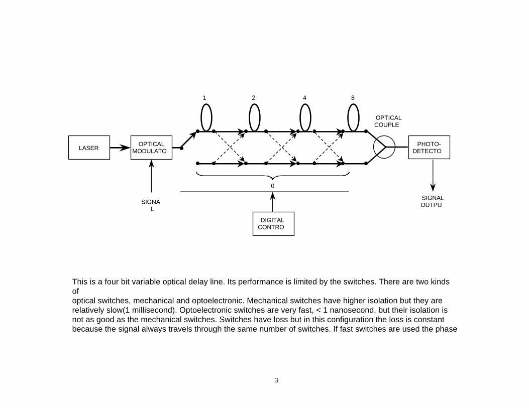
This is a four bit variable optical delay line. Its performance is limited by the switches. There are two kindsofoptical switches, mechanical and optoelectronic. Mechanical switches have higher isolation but they arerelatively slow(1 millisecond). Optoelectronic switches are very fast, < 1 nanosecond, but their isolation isnot as good as the mechanical switches. Switches have loss but in this configuration the loss is constantbecause the signal always travels through the same number of switches. If fast switches are used the phaseof an analog signal can be rotated thereby generating an offset frequency or a chirp if desired.
4
LASEROPTICAL
MODULATOR
PHOTO-DETECTO
R
OPTICALCIRCULATO
R
FILTE
RFMIXER
PHOTO-DETECTO
R
FARADAYROTATING
1/2MIRROR
FREQUENCY
REFERENCE
VARIABLEFIBEROPTIC
DELAY LINE
OPTICAL FIBERTO BE
STABILIZED
OUTPUT
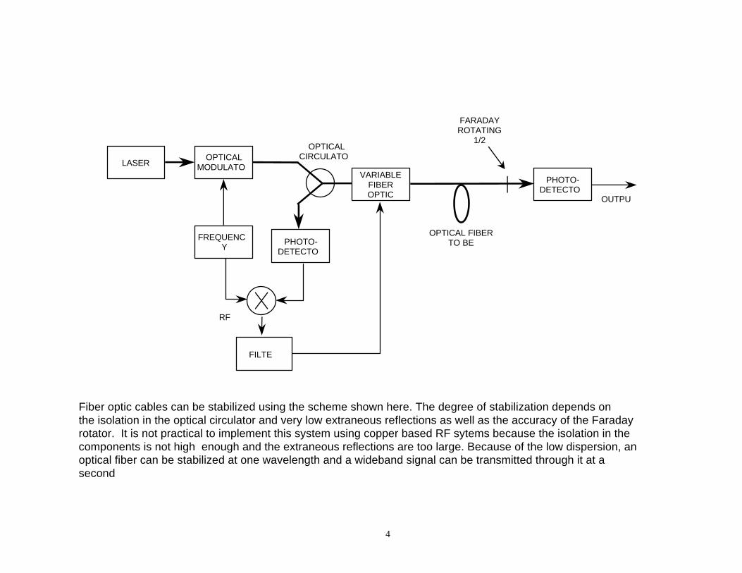
Fiber optic cables can be stabilized using the scheme shown here. The degree of stabilization depends onthe isolation in the optical circulator and very low extraneous reflections as well as the accuracy of the Faradayrotator. It is not practical to implement this system using copper based RF sytems because the isolation in thecomponents is not high enough and the extraneous reflections are too large. Because of the low dispersion, anoptical fiber can be stabilized at one wavelength and a wideband signal can be transmitted through it at asecondwavelength.
5
-16
-17
-15
-14
-13
-12
-181 10 100 1,000 10,000 100,000
TAU (seconds)
SIG
MA
10
10
10
10
10
10
10
STABILIZED
UNSTABILIZED
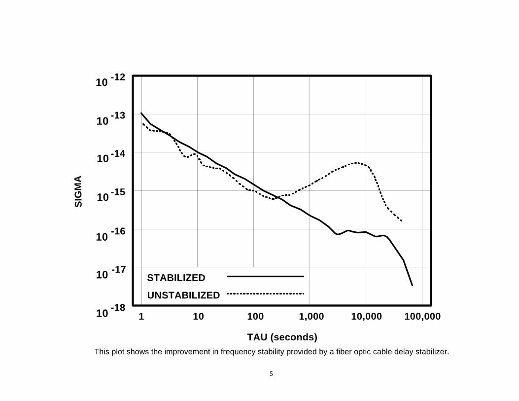
This plot shows the improvement in frequency stability provided by a fiber optic cable delay stabilizer.
6
LASER OPTICALMODULATO
R
RFFILTE
R
PHOTO-DETECTO
R
RFAMPLIFIE
R
MODULATEDOPTICALCARRIEROUTPUT
OPTICALCOUPLE
R
FIBEROPTIC
DELAY LINE
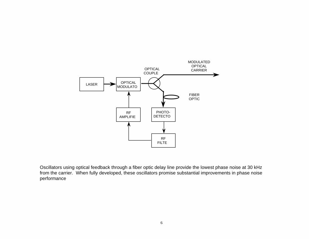
Oscillators using optical feedback through a fiber optic delay line provide the lowest phase noise at 30 kHzfrom the carrier. When fully developed, these oscillators promise substantial improvements in phase noiseperformanceof precision radar systems.
7
LASEROPTICAL
MODULATOR
PHOTO-DETECTO
R
RFSWEEP
GENERATOR
SIGNALPROCESSO
ROUTPU
T
MAGNITU
DISTANCE
SENSOR
REFERENCEMIRROR
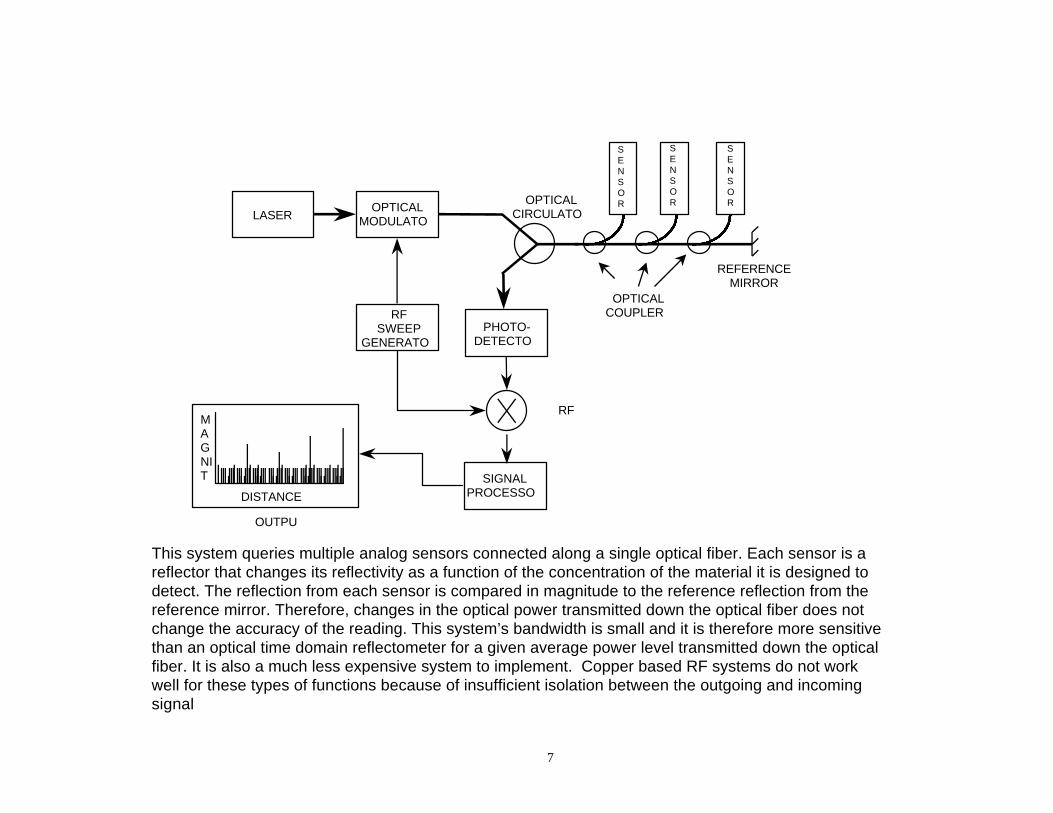
This system queries multiple analog sensors connected along a single optical fiber. Each sensor is areflector that changes its reflectivity as a function of the concentration of the material it is designed todetect. The reflection from each sensor is compared in magnitude to the reference reflection from thereference mirror. Therefore, changes in the optical power transmitted down the optical fiber does notchange the accuracy of the reading. This system’s bandwidth is small and it is therefore more sensitivethan an optical time domain reflectometer for a given average power level transmitted down the opticalfiber. It is also a much less expensive system to implement. Copper based RF systems do not workwell for these types of functions because of insufficient isolation between the outgoing and incomingsignalpaths and excessive extraneous reflections.
OPTICALCIRCULATO
R
OPTICALCOUPLER
S
RFMIXER
SENSOR
SENSOR
8
LASEROPTICAL
MODULATOR
PHOTO-DETECTO
R
RF SWEEPGENERATO
R
OPTICALCIRCULATO
R
FILTE
OPTICALDELAYLINE
RFMIXER
REFERENCEOSCILLATO
R
OUTPUT
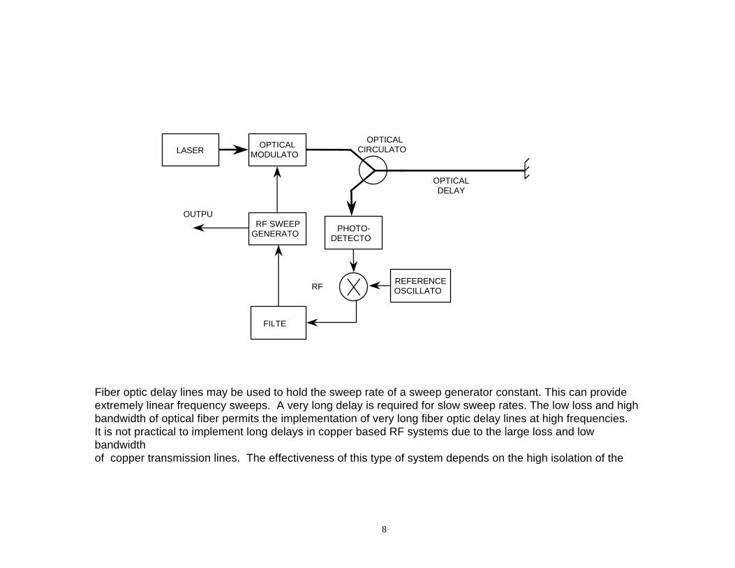
Fiber optic delay lines may be used to hold the sweep rate of a sweep generator constant. This can provideextremely linear frequency sweeps. A very long delay is required for slow sweep rates. The low loss and highbandwidth of optical fiber permits the implementation of very long fiber optic delay lines at high frequencies.It is not practical to implement long delays in copper based RF systems due to the large loss and lowbandwidthof copper transmission lines. The effectiveness of this type of system depends on the high isolation of theoptical circulator which is many orders of magnitude greater than the isolation of an RF circulator.
9
3.0 Fiber Optic Reference Signal Distribution and Cable Stabilizer Implementedin SRTM
3.1 Introduction
The Shuttle Radar Topography Mission (SRTM) will use radar interferometry to map 80% of the earth’ssurface in 3D in 11 days (Ref. 1,2). In radar interferometry, two radar images are taken from slightlydifferent locations. Differences between these images allow for the calculation of surface elevation, orchange. To get two radar images taken from different locations the SRTM hardware consists of onetransmit/receive antenna array in the shuttle payload bay and a receive only antenna array attached to theend of a mast extended 60 meters out from the shuttle. The accuracy of the produced maps partly dependson accurate knowledge of delay variations between the two paths of received signals.
3.2 Problem
The problem is that the temperature of the mast and outboard electronics varies as the shuttle flies in andout of the earth’s shadow during each orbit. Since cable delay varies with temperature, this results inexcessive delay variations in the coaxial cables and outboard electronics that would reduce mappingaccuracy. A solution would be to inject a known phase into the inboard and outboard electronics tocalibrate out the system phase vs. temperature fluctuations. But any cable that would carry this referencesignal along the mast would be affected too. Therefore a self-compensating reference distribution to theoutboard had to be designed in order to meet the system requirements.
When in orbit the mast cables will change temperature semi-sinusoidally by as much as 12 degrees Cpeak-to-peak with a 90 minute orbital period. The average temperature of the cables will be between -10o
C and –60o C. Using coaxial cables with the very lowest thermal coefficient of delay (TCD) available stillleaves us with a thermal coefficient of delay of up to 40 ppm/oC. In our temperature range the delaychange without compensation could be as high as 5 ps. This is equal to 100 degrees of phase at thereference signal frequency of 5.3 GHz. The maximum allowable phase change allocated to the down-linkcoaxial cable by the system designers is 3 degrees.
3.3 Solution
Two approaches to this problem were considered. The first approach was to actively stabilize the delay ofthe cable through which the received echo signals traveled from the end of the mast back to the shuttlebay. The second approach was to inject a reference tone which would accompany the ground echo signalsand be used to later extract the phase of the ground echo signals using computer signal processing of themission data.
The first approach was abandoned for several reasons. Active delay compensation doesn’t work well in acoaxial cable system because of large reflections and low isolation in the system components. Even thoughdelay compensation works very well for fiber optic links, the designers didn’t want to risk the use of newtechnology to carry the received radar signals from the end of the mast back to the shuttle bay. Loss of thislink would scrub the mission.
The designers chose to use the second approach. Should the fiber optic link fail, a backup reference tonewill be injected, uncompensated into the mast cables, traveling up the mast, then injected back down themast now to accompany the ground echo signal. The reference tone phase will be assumed to vary by thesame amount in the up-mast cable as in the identical down-mast cables and its phase contribution will beextracted accordingly.
10
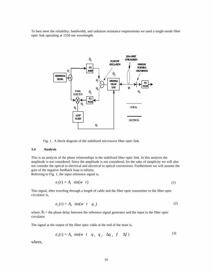
To best meet the reliability, bandwidth, and radiation resistance requirements we used a single-mode fiberoptic link operating at 1550 nm wavelength.
Fig. 1. A block diagram of the stabilized microwave fiber optic link.
3.4 Analysis
This is an analysis of the phase relationships in the stabilized fiber optic link. In this analysis theamplitude is not considered. Since the amplitude is not considered, for the sake of simplicity we will alsonot consider the optical to electrical and electrical to optical conversions. Furthermore we will assume thegain of the negative feedback loop is infinity.Referring to Fig. 1, the input reference signal is,
(1)
This signal, after traveling through a length of cable and the fiber optic transmitter to the fiber opticcirculator is,
(2)
where, θ1 = the phase delay between the reference signal generator and the input to the fiber opticcirculator.
The signal at the output of the fiber optic cable at the end of the mast is,
(3)
where,
FOXMTR
FORCVR
FORCVR
FARADAYROTATING
HALF MIRROR
FO 3 PORTCIRCULATOR
100m MAST OPTICALFIBER
φφ
REFERENCESIGNAL
VARIABLEDELAYLINE
LOOPFILTER
e1
θ1
θ2
θ3
e2
e3
e4
e5e6
e7
OPTICAL
ELECTRICAL
PHASEDETECTOR
e t A t1 1( ) sin( )= ⋅ ⋅ω
e t A t2 2 1( ) sin( )= ⋅ ⋅ +ω θ
e t A t3 3 1 2 2( ) sin( )= ⋅ ⋅ + + + + +ω θ θ θ φ φ∆ ∆
11
θ2 = the delay through the variable fiber optic delay line,
∆θ2 = the delay change in the variable fiber optic delay line,
φ = the nominal delay of the optical fiber in the mast, and
∆φ = the change in delay of the optical fiber in the mast.
The reflected signal at the return port of the fiber optic circulator is,
(4)
The reflected signal at the input of the phase detector is,
(5)
where, θ3 = the phase delay from the reflected port of the circulator through the fiber optic receiver to thephase detector.
The output of the phase detector is the product of (1) and (5),
or,
After low pass filtering (6) we get the loop error signal,
(7)
It can be shown that there are values for θ2 that result in (7) being equal to zero. The loop will force θ2 to
one of these values thereby forcing (7) to equal zero. Thereafter, assuming θ1 and θ3 are constant, for any
change in ∆φ the loop will force ∆θ2 to change by an equal amount in the opposite direction to keep (7)
equal to zero. In other words (∆θ2) will be forced to equal (-∆φ).
The result of this is made clear if we substitute (-∆φ) for (∆θ2) in (3),
(8)
It can be seen that variations in the delay of the optical fiber, ∆φ, fall out and the phase of the outputsignal is constant relative to the phase of e1, the reference signal.
e t A t4 4 1 2 22 2( ) sin[ ( ) ( )]= ⋅ ⋅ + + ⋅ + + ⋅ +ω θ θ θ φ φ∆ ∆
e t A t5 5 1 2 2 32 2( ) sin[ ( ) ( ) ]= ⋅ ⋅ + + ⋅ + + ⋅ + +ω θ θ θ φ φ θ∆ ∆
e t e t e t6 1 5( ) ( ) ( )= ⋅
e t A
t6 6 1 2 2 3
1 2 2 3
2 2
2 2 2
( ) {cos[ ( ) ( ) ]
cos[ ( ) ( ) ]}
= ⋅ + ⋅ + + ⋅ + + +⋅ ⋅ + + ⋅ + + ⋅ + +
θ θ θ φ φ θω θ θ θ φ φ θ
∆ ∆∆ ∆
e t A7 7 1 2 2 32 2( ) cos[ ( ) ( ) ]= ⋅ + ⋅ + + ⋅ + +θ θ θ φ φ θ∆ ∆
e A t3 8 1 2( ) sin[ ( )]∆ ∆ ∆φ ω θ θ φ φ φ= ⋅ ⋅ + + + + −
(6)
12
3.5 Control Loop Design
We used a thermally controlled spool of optical fiber as a variable delay line. Its design is described in thenext section. The relatively long, 180 second, time constant of this complex variable delay complicated theloop design. This delay provided the first pole in the design. Another zero and another pole were addedusing active electronics. We simulated the response of the loop using SPICE. The control loop designachieved the required acquisition range, tracking range and stability and its simulated performance wasverified by extensive testing.
To test the loop’s characteristics, we used a network analyzer to measure the phase difference between itsinput and output. We placed the long mast fiber in an oven and varied its temperature to simulate orbitalvariations expected in the mission. Because air provides undesired thermal paths that change the timeconstant of the optical fiber spool, we placed the fiber spool in a vacuum chamber during testing toachieve the in situ thermal response.
A real time data acquisition system collected network analyzer phase and amplitude measurements foranalysis.
3.6 Photonic Hardware Description
The unique feature of this stabilized fiber optic link is the hardware used to implement it. To ourknowledge it is the first use of a 1550 nm single-mode fiber optic system and the first microwave fiberoptic system used in a space application. The hardware was, for the most part, commercial-off-the-shelf(COTS). However, it was carefully chosen and modified as needed to operate reliably in the spaceenvironment to which it would be exposed. An operating wavelength of 1550 nm was used because thelaser was considered to be more reliable and the optical fiber has lower ionizing radiation inducedattenuation at this wavelength.
Uniphase Telecommunications Products (UTP) Transmission Systems Division fabricated the stabilizedmicrowave fiber optic link under contract with JPL. This included all of the components shown in theblock diagram (Fig. 1) with the exception of the reference signal generator. The fiber optic transmittermodule is a slightly modified version of their COTS Small Integrated Transmitter Unit (SITU).
The SITU consists of a 1550 nm high power single-mode CW laser followed by a Mach-Zehnder
modulator. The optical output power of the SITU is ≥ 5 dBm and the bandwidth is 1-18 GHz. The relative
intensity noise (RIN) is ≤ -150 dB/Hz and Vπ is ≤ 7 volts at 2 GHz. The non-operating temperature rangeis –55oC to +85oC and its operating temperature is 0oC to +60oC (Ref. 3). The entire stabilized fiber opticsystem must meet its specifications when the SITU is subjected to any 10oC peak-to-peak temperaturevariation within the temperature range of +5oC to +45oC.
The 3 port circulator is a COTS device fabricated by E-Tek Dynamics. Its specified wavelength is 1550
nm ± 20 nm. Its insertion loss from 0oC to 60oC is < 1.3 dB over its entire wavelength range. Its
minimum peak isolation is 45 dB. The optical return loss is ≤ -50 dB.
The FRHM is a modified COTS device fabricated by E-Tek Dynamics. It was modified from a full mirrorto a half mirror to allow half of the light to pass through into another optical fiber on the backside of themirror. Its center wavelength is 1550 nm with a spectral width of 30 nm.
13
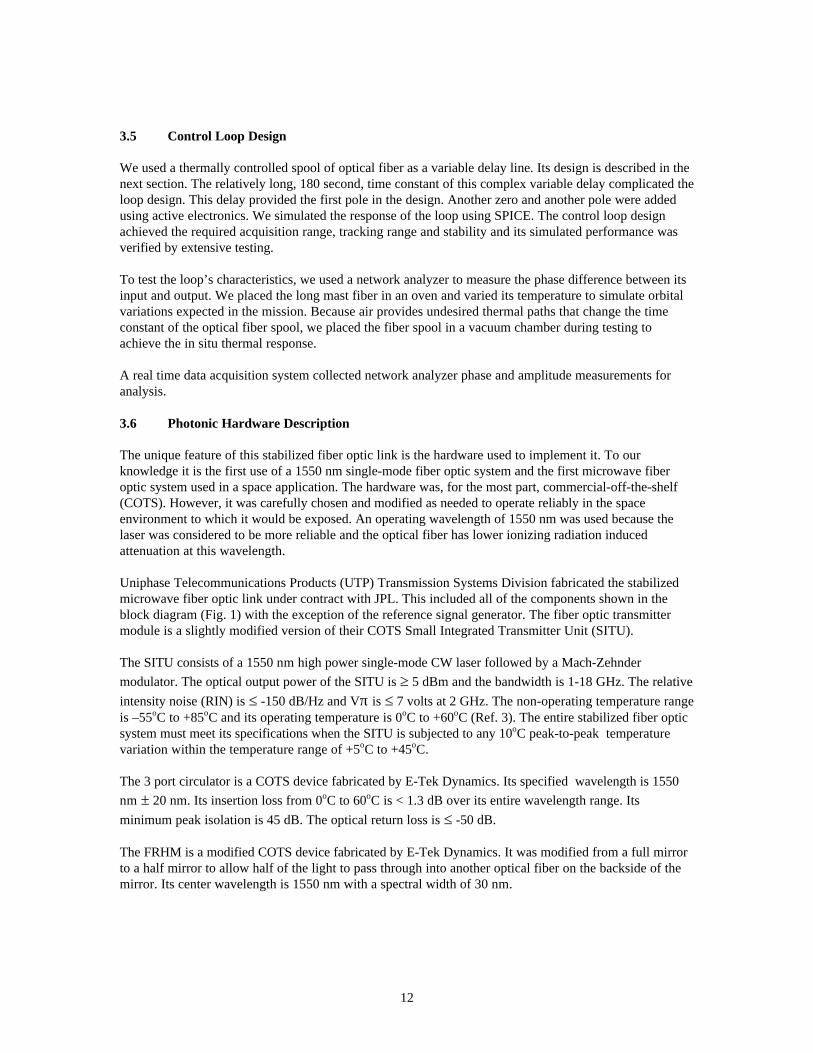
The following table contains typical tests applied to devices fabricated by E-Tek Dynamics (Ref. 4).
Temperature Cycling -40oC to +80oCfor 14 days;rate 1oC/min; dwell 1 hour at the extremes
High temperature bake 80oC for 2,000 hoursVibration 3 axis 20 g’s at 20 ~2,000 HzShock 3 axes, 100 g’s, 11msMax. Tensile Strength 10 N force for 10 seconds
Table 1. Typical tests applied to components by E-Tek Dynamics
The fiber optic photodetector is a COTS device fabricated by Lasertron and is incorporated into the fiberoptic receiver unit fabricated by UTP. Its has a 1,000 ohm output resistor and a bandwidth of 0.01 to 12GHz when loaded with 50 ohms. The spectral range is 1100 nm to 1650 nm. The responsivity is 0.8 A/W
at 1300 nm and the optical return loss is ≥ 40 dB. The operating temperature range is –40oC to +85oC.This device is tested to Bellcore Technical Advisory TA-TSY-000983 at minimum (Ref. 5).
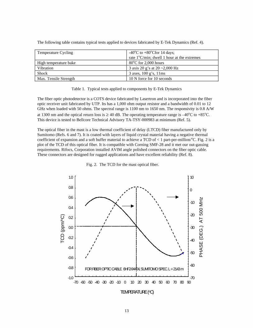
The optical fiber in the mast is a low thermal coefficient of delay (LTCD) fiber manufactured only bySumitomo (Refs. 6 and 7). It is coated with layers of liquid crystal material having a negative thermalcoefficient of expansion and a soft buffer material to achieve a TCD of < 1 part-per-million/oC. Fig. 2 is aplot of the TCD of this optical fiber. It is compatible with Corning SMF-28 and it met our out-gassingrequirements. Rifocs, Corporation installed AVIM angle polished connectors on the fiber optic cable.These connectors are designed for rugged applications and have excellent reliability (Ref. 8).
Fig. 2. The TCD for the mast optical fiber.
-1.0
-0.8
-0.6
-0.4
-0.2
0.0
0.2
0.4
0.6
0.8
1.0
-70 -60 -50 -40 -30 -20 -10 0 10 20 30 40 50 60 70 80 90
TEMPERATURE (oC)
TC
D (
ppm
/o C)
-70
-60
-50
-40
-30
-20
-10
0
10
PH
AS
E (
DE
G.)
AT
500
MH
z
FOR FIBER OPTIC CABLE 6HF2-94404, SUMITOMO SPEC. L = 2143 m
14
The variable delay line is a thermally controlled winding of optical fiber. It consists of a thin walledaluminum cylinder which has approximately 260 meters of optical fiber bonded to its outer surface andresistive foil heaters on the inside wall. The base of the aluminum cylinder is heat sunk to the chassis ofthe fiber optic transmitter module through a fiber glass washer which provides a calibrated thermalresistance. The chassis is bolted to the cooling plate in the spacecraft. The optical fiber is standard single-mode communications fiber manufactured by Spectran.
Thermal expansion or contraction of the aluminum cylinder and optical fiber, and thermally inducedchange in the index of refraction of the optical fiber all contribute to the delay change through the opticalfiber when it is heated or cooled. The phase delay change versus temperature is 59o/oC.
3.7 Tests and Results
The fiber optic cable assemblies were tested many times for connector reliability and TCD over atemperature range as wide as –60oC to +85oC. Some cable tests were run in conjunction with testing otherparts of the system. In these cases the temperature range was typically from room temperature down to –
50oC and then cycled sinusoidally ± 8oC around 50oC. In addition to these tests the flight cables were
cycled sinusoidally ± 10oC around –25oC for two weeks.
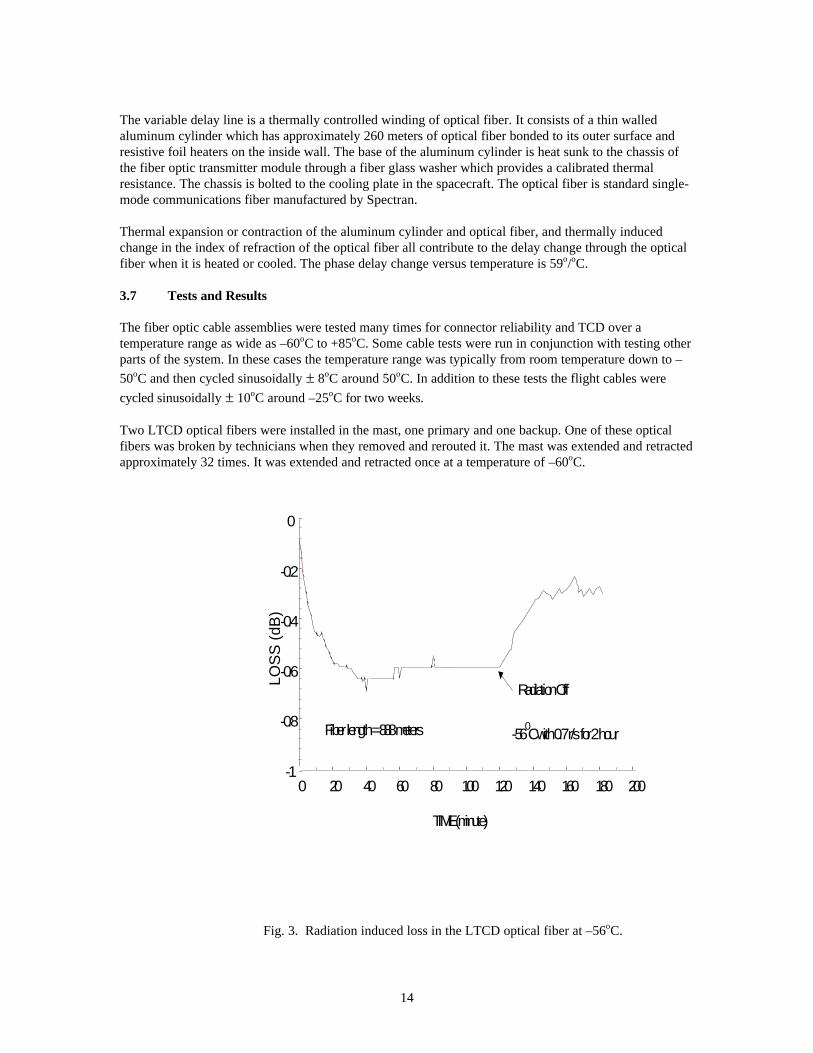
Two LTCD optical fibers were installed in the mast, one primary and one backup. One of these opticalfibers was broken by technicians when they removed and rerouted it. The mast was extended and retractedapproximately 32 times. It was extended and retracted once at a temperature of –60oC.
Fig. 3. Radiation induced loss in the LTCD optical fiber at –56oC.
-56 0C with 0.7 r/s for 2 hour
Radiation Off
-1
-0.8
-0.6
-0.4
-0.2
0
0 20 40 60 80 100 120 140 160 180 200
TIME (minute)
LOS
S (
dB)
Fiber length = 888 meters
15
With the exception of the mast fiber that was broken in the rerouting incident, there were no cable orconnector failures. One LTCD optical fiber was subjected to ionizing radiation at –60oC. A plot of thisdata is shown in Fig. 3.
For the thermal vacuum test we placed the fiber optic transmitter, receiver, and optical fibers all in thesame vacuum test chamber. Each of these three system components was subjected to a different
temperature range. The transmitter was subjected to a sinusoidal temperature variation of ± 10oC over theaverage temperature range from 5oC to 45oC. The receiver was subjected to a sinusoidal temperature
variation of ± 10oC over the average temperature range from -40oC to +15oC. The optical fiber wassubjected to sinusoidal temperature variation of 12oC over the average temperature range from –10oC to –60oC.
The stabilized fiber optic link locked up properly and met its 3o phase stability specification over the entirerange of test temperatures.
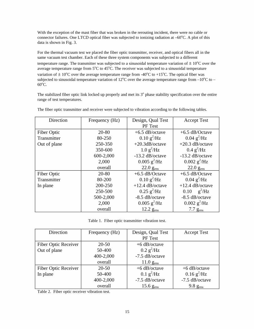
The fiber optic transmitter and receiver were subjected to vibration according to the following tables.
Direction Frequency (Hz) Design, Qual TestPF Test
Accept Test
Fiber OpticTransmitterOut of plane
20-8080-250
250-350350-600
600-2,0002,000overall
+6.5 dB/octave0.10 g2/Hz
+20.3dB/octave1.0 g2/Hz
-13.2 dB/octave0.005 g2/Hz
22.0 grms
+6.5 dB/Octave0.04 g2/Hz
+20.3 dB/octave0.4 g2/Hz
-13.2 dB/octave0.002 g2/Hz
22.0 grms
Fiber OpticTransmitterIn plane
20-8080-200
200-250250-500
500-2,0002,000overall
+6.5 dB/Octave0.10 g2/Hz
+12.4 dB/octave0.25 g2/Hz
-8.5 dB/octave0.005 g2/Hz
12.2 grms
+6.5 dB/Octave0.04 g2/Hz
+12.4 dB/octave0.10 g2/Hz
-8.5 dB/octave0.002 g2/Hz
7.7 grms
Table 1. Fiber optic transmitter vibration test.
Direction Frequency (Hz) Design, Qual TestPF Test
Accept Test
Fiber Optic ReceiverOut of plane
20-5050-400
400-2,000overall
+6 dB/octave0.2 g2/Hz
-7.5 dB/octave11.0 grms
Fiber Optic ReceiverIn plane
20-5050-400
400-2,000overall
+6 dB/octave0.1 g2/Hz
-7.5 dB/octave15.6 grms
+6 dB/octave0.16 g2/Hz
-7.5 dB/octave9.8 grms
Table 2. Fiber optic receiver vibration test.
16
3.8 Conclusion
The SRTM project had a unique problem with the systems stability that was best resolved with amicrowave fiber optic link. A suitable fiber optic link was designed and implemented using primarilyCOTS hardware with minor modifications where needed to improve reliability. To our knowledge this isthe first 1550 nm single-mode fiber optic link to be implemented for use in space.We extensively tested the stabilized fiber optic link over the entire worst case range of potentialenvironmental conditions including temperature, vacuum, and vibration. It met all of its specificationsand worked flawlessly without a single failure in any part.This work has shown that complex photonic systems implemented with carefully chosen and minimallymodified COTS devices can meet the reliability requirements of some space applications.
3.9 Acknowledgements:
The authors would like to thank Dr. X. S. Yao, for his helpful inputs, Dr. Boris Lurie, for his help withthe control loop analysis, Mimi Paller and Louise Veilleux for their support of this effort, Edward Caro,for his support and for giving us the benefit of his vast experience, Brad Finamore, for his expertise inautomating the test system and running tests, and the entire SRTM team for their help which was alwaysthere when we needed it. We also thank Dr. Lute Maleki for his guidance throughout the course of thiswork.
The research described in this paper was performed at the Jet Propulsion Laboratory, California Instituteof Technology, under a contract with the National Aeronautics and Space Administration.
Reference herein to any specific commercial product, process, or service by trade name, trademark,manufacturer, or otherwise, does not constitute or imply its endorsement by the United States Governmentor the Jet Propulsion Laboratory, California Institute of Technology.
3.10 References:
1. George Lutes, Dalia McWatters, and Meirong Tu, “A 60 Meter Delay Stabilized MicrowaveFiber Optic Link for 5.3 GHz Reference Signal Distribution on the Shuttle,” Radar TopographicMapper
2. Seeing Earth’s Surface in 3D,http://southport.jpl.nasa.gov/html/projects/srtm-what.html
3. Specification sheet for the SITU, Uniphase Telecommunications Products, Inc., Transmission SystemsDivision, 500 Horizon Drive, Chalfont, PA 18914.
4. Specification sheet for the Faraday mirror, E-Tek Dynamics, 1885 Lundy Ave., San Jose, CA 95131
5. Product Guide, Lasertron, Inc., 37 North Ave., Burlington, MA01803
6. Y. Shuto, F. Yamamoto, and Y. Takeuchi, “High-Temperature Stability of Optical Transmission Properties Attained by Liquid-Crystal Polymer Jacket,” J. Lightwave Tech., vol.LT-4, No. 6, June 1986.
7. Lutes, G., and W. Diener, "Thermal Coefficient of Delay for Various Coaxial and Fiber-Optic Cables,"TDA PR 42-99, July-Sept. 1989, pp. 43-59, Nov. 15, 1989.
17
8. Specification sheet, RIFOCS Corp., 1340 Flynn Road , Camarillo, California 93012
18
4.0 Safe use of the UTP Fiber Optic Transmitter to be used on SRTM
The UTP fiber optic system is operated as a Class 1 system being completely enclosed during operationaccording to ANSI Standard Z136.2. However, the Service Group classification, which provides for safetyduring service when connectors are disconnected by service personnel, is Class 3a.
Although the UTP fiber optic transmitter contains an enclosed Class 3b laser its output passes through aMach-Zehnder modulator before it is accessible outside of the module which contains it. The module isnot serviceable in the field and should never be opened except at the manufacturers facilities. The light outof the modulator is only accessible through a single-mode optical fiber which passes through the wall ofthe module to the outside world and is terminated with a standard single-mode fiber optic connector.
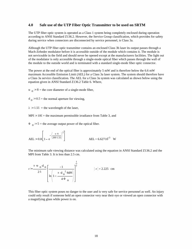
The power at the end of the optical fiber is approximately 5 mW and is therefore below the 6.6 mWmaximum Accessible Emission Limit (AEL) for a Class 3a laser system. The system should therefore havea Class 3a service classification. The AEL for a Class 3a system was calculated as shown below using theequation given in ANSI Standard Z136.2 Table 6. Where,
ω o 8 = the core diameter of a single-mode fiber,
d o 0.5 = the normal aperture for viewing,
λ 1.55 = the wavelength of the laser,
MPI 100 = the maximum permissible irradiance from Table 3, and
Φ o 5 = the average output power of the optical fiber.
AEL 0.8 1 e
π 9.
200 1.55.
2
. AEL 6.62710 3.= W
The minimum safe viewing distance was calculated using the equation in ANSI Standard Z136.2 and theMPI from Table 3. It is less than 2.5 cm.
rπ ω o
. d o.
2 λ.1
ln 1π d o
2. MPI.
4 Φ o.
1
2.
r 2.225= cm
This fiber optic system poses no danger to the user and is very safe for service personnel as well. An injurycould only result if someone held an open connector very near their eye or viewed an open connector witha magnifying glass while power is on.
19
5.0 Radiation Darkening of the SRTM Optical Fiber
Reference: IOM #CEB-514-E-96-14 from C. Barnes to G. Lutes 2/19/96
After further consultation and study I have concluded that no additional shielding is needed on the optical fiberin the SRTM boom. The fiber we have decided to use is a special low thermal coefficient of delay fiber,SFH2-97409A, manufactured by Sumitomo Electric Industries, Ltd. The coating on this fiber provides morethan the suggested equivalent of 1 mil of aluminum shielding for the fiber.
The following is a history of the radiation shielding concern and an explanation of our conclusion that noadditional shielding is needed.
Dr. Charles Barnes, who is an internationally known expert on radiation effects on optical fiber andother photonic parts, works here at JPL in Section 5070. In February 1996 we asked him to perform astudy on radiation effects on the proposed photonic equipment for SRTM. This included the degree ofdarkening of the SRTM fiber.
Michael Cherng, an expert on the space radiation environment, provided Charles with an estimate ofthe total radiation dose that would be expected in the SRTM environment. This estimate assumed theequivalent of 1 mil of aluminum shielding around the fiber. The 1 mil of aluminum shielding is used asa baseline because it eliminates most of the low energy radiation and leaves only the more predictablehigh energy radiation.
Using Michael’s estimate of the total radiation dose Charles concluded that the only potentiallysignificant radiation effect for the SRTM fiber optic link is the possibility of radiation inducedattenuation in the 60 m long single-mode optical fiber. Our choice of a 1550 nm wavelength systemreduces the radiation effects for all of the link components including the fiber.
By analogy with previous work in the literature on single-mode fibers Charles estimated,conservatively, that the radiation induced darkening would not exceed 0.54 dBo (optical) over the life ofthe SRTM mission. This is equivalent to 1.08 dBe for the RF signal.
The assumption of the equivalent of 1 mil of aluminum shielding brought up concerns about how wewould achieve that. Adding 1 mil of aluminum shield would pose several problems for the designersand implementers of the boom, such as the additional weight and the methodology for installing it. Thisprompted further study of the need for additional shielding.
Our conclusion that no additional shielding will be needed on the fiber is based on,
a radiation test to verify the conclusions of the study, and
analysis of the radiation shielding provided by the coating on the optical fiber.
We exposed an 880 meter long sample of the optical fiber to 5 krads of radiation which is twice theequivalent to the total dose the fiber would see during the SRTM mission. During the test the fiber wasmaintained at -56 degrees C, the lowest temperature the fiber is expected to see during the mission.This was done to simulate the worst case condition since radiation darkening increases as thetemperature decreases.
20
During the test the optical fiber darkened by 0.6 dBo. Since the test fiber is 8.8 times longer than theactual fiber used on the SRTM boom the attenuation of the test fiber is divided by 8.8 which gives anattenuation of only 0.07 dBo or 0.14 dBe over the duration of the mission.
The radiation source in the JPL radiation test facility emits only high energy radiation. Therefore, thetest only verified the conclusions of the study but did not resolve the question of shielding needed toreduce low energy radiation.
I had further discussions with Michael Cherng who verified that if the product of density times thicknesswas equal to that of aluminum the shielding provided by other materials would be nearly the same. Ithen went to the manufacturer of the optical fiber to get the density and thickness of the coating materialon the fiber. I was also able to get an average density for the fiber coating by weighing the fiber,measuring its volume, and subtracting the weight and volume of the bare fiber which I already knew. Idid this just to verify the information the vendor gave me.
The result is as follows.
One mil is 25.5 microns and the density of aluminum is 2713 kg/m3 so the product of the thickness andthe density is 69,182. The fiber coating consists of three layers, a layer of silicone next to the fiber, alayer of liquid crystal material, and finally a color coat of UV cured polymer. The density of thesilicone and color coat are the same at 1,100 kg/m3 and their total thickness is 127.5 microns so theproduct of the thickness and density for these layers is 140,250. Finally the density of the liquid crystalmaterial is 1,400 kg/m3 and its thickness is 310 microns the product of the thickness and density for thislayer is 434,000.
To obtain the shielding margin add the products of the coating layers to get 574,250 and then divide bythe product of 1 mil of aluminum which is 69,182 to get a margin of 8.3 times. In other words thecoating on the fiber is equivalent to approximately 8.3 mils of aluminum.
In conclusion we see no need for additional shielding on the fiber.
Reference: Interoffice Memo #335.10-97-013
Date: 10/23/97To: Brian Harrington Sect.: 352From: George Lutes Sect.: 335
21
6.0 DEVELOPMENT OF FIBER OPTIC CABLE ASSEMBLIES FOR SPACEAPPLICATIONS
6.1 Introduction
Fiber optic cable and connector manufacturers are working with a consortium of NASA and privateindustry partners to develop a family of reliable fiber optic cable assemblies for space applications. Thispaper explains some of the problems they are addressing. We start by breaking fiber optic cable assembliesinto four major categories and discussing the problems or potential problems of each category. Some ofthe materials issues are discussed with pros and cons. Finally, we make recommendations for cableassemblies which are available now and discuss future trends.
6.2 Basics
There are two main categories of fiber optic cable assemblies, using terms coined by John Kolasinski atGoddard,
Pull-proof, and
Non-pull-proof.
There are also two main categories of cable construction,
tight buffered, and
loose tube.
There are, therefore, four possible main categories of fiber optic cable assemblies,
pull-proof with tight buffered cable, (PPT)
pull proof with loose tube cable, (PPL)
non-pull-proof with tight buffered cable (NPPT), and
non-pull-proof with loose tube cable (NPPL).
Most cable assemblies use springs within the connectors to hold the ends of the fibers together undertension.
If two non-pull-proof cable assemblies are mated together in a feedthrough and you pull on one or both ofthe cables the spring(s) will be compressed and the mating ends of the fibers will be separated.
In pull-proof cable assemblies strength members in the cable are attached to the connector body such thatthe tension from pulling on the cable is applied to the connector body and to the feedthrough by way of theconnector nut. Non of the tension is applied to the fiber or to the ferrule which holds it so the fibers arenot separated.
When pull-proof cable assemblies are mated the springs are compressed and the fibers are pushed backinto the cable for about 1 mm.
In loose tube fiber optic cable the fiber is contained in a tube which is many times the diameter of thefiber. This decouples the fiber from the other parts of the cable such as the strength members, and jacket.
22
In this paper all other cable constructions will be lumped into the tight buffer category which will includecables with widely differing degrees of fiber movement relative to the other cable parts.
6.3 Problems
If a tight buffered cable is subjected to large temperature variations the cable will expand or shrink. Sincethe other cable materials have a different thermal coefficient of expansion than the fiber, the fiber will beplaced in tension or compression depending on whether the cable has expanded or shrunk. This causesstress on the fiber which can result in excess fiber loss and variations in the amplitude of the opticalsignal. This problem is worse for cables in which the fiber is tightly coupled to the other parts of the cable.The performance of some tight buffered cable over a wide temperature range can be quite good when thefiber is loosely coupled to the other parts of the cable.
The performance of loose tube cable is very good over a wide temperature range because the fiber is veryloosely coupled to the other cable parts. However, in a loose tube cable assembly care must be taken toinsure that the cable parts other than the fiber never get longer than the fiber due to thermal expansion ortension. If this happens the fiber will be stressed and could break.
In NPPT and NPPL cable assemblies tension will result in inadequate mating pressure or separation at thefiber interface. Tension can result from improper routing of the cable, or inadequately constrained cableduring vibration. The result of this can vary from amplitude variations on the optical signal to a completeloss of signal.
If the construction of the cable in a PPT cable assembly is such that the fiber cannot be pushed into thecable by about 1 mm the fiber will bend within the connector body. In this case the fiber could bend sosharply that the attenuation would increase appreciably or it could break. In a PPL cable assembly this isnot a problem because the fiber is free to move in the tube.
The PPL cable assembly is the most rugged of the four categories. Cable strength members are attached tothe connector body so that tension on the cable is transferred to the feedthrough and not to the fiber.Therefore, when the cable is pulled the fiber interfaces are not separated. The fiber is free to be pushedinto the cable upon mating and the fiber is isolated from stress induced by temperature variations,vibration, and cable flexure. However, care must be taken to ensure that there is enough excess fiber in thecable to allow for thermal expansion of the other cable parts.
6.4 Materials and Processes
The materials used in manufacturing commercial fiber and its buffer are generally suitable for spaceapplications. However, the materials used in manufacturing the other cable parts in commercial cable aregenerally not suitable for space applications. Fortunately, several cable manufacturers have the materialtechnology and processes to fabricate suitable cable.
One of the best jacketing material is expanded Teflon. It remains flexible at extremely low temperatures, itis strong, and it is relatively inert and free from outgassing.
23
7.0 A Comparison of Gore-Tex 0.190” Diameter Coaxial Cable to Fiber OpticCable
7.1 Introduction
A cable is needed for SRTM to transmit microwave signals over the length of a 60 meter boom. Thisboom is folded up and stowed in an enclosure during launch. Once in orbit the boom is expanded to itsfull length. This folding and unfurling requires the cable to be very flexible and of small diameter. Aprevious study identified Gore-Tex 0.190” diameter cable to be one of the best coaxial cables for such anapplication. However, the performance of this cable falls short of some of the requirements of SRTM.
Fiber optic cable was identified as a potential alternative to coaxial cable for this application. This studywas initiated to compare the two types of cable to enable engineering to make an informed decision aboutwhat type of cable is to be used.
7.2 Assumptions
Because the design of SRTM is still changing some assumptions were made for the sake of expediency.It is assumed that the cable will not be unfurled in a straight line so it will be longer than the boom. Forthe sake of this study it is assumed that the cable will be 100 meters long. It is also assumed that a cablelarger in diameter than the Gore-Tex 0.190” diameter cable would not be practical from a mechanicalstandpoint.
7.3 Comparison
Since the Gore-Tex cable was determined to be one of the best for this application it is compared to atypical fiber optic cable. Five plots showing the performance of the Gore-Tex 0.190” coaxial cable wereused from the Gore catalog. The performance of a typical fiber optic cable was superimposed on the Goreplots.
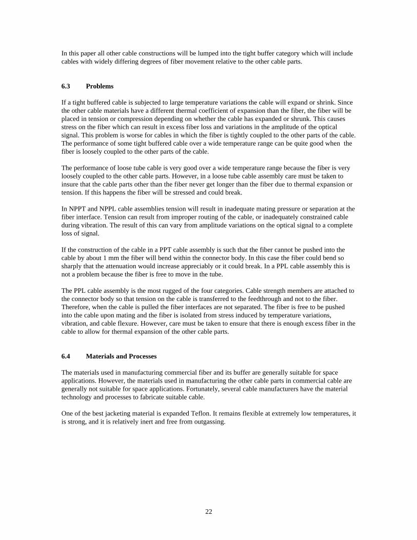
In Fig. 1 the insertion loss change vs temperature is plotted. The loss in a typical fiber optic cable is 0.05dB/km over the temperature range of +85 oC to -60 oC.
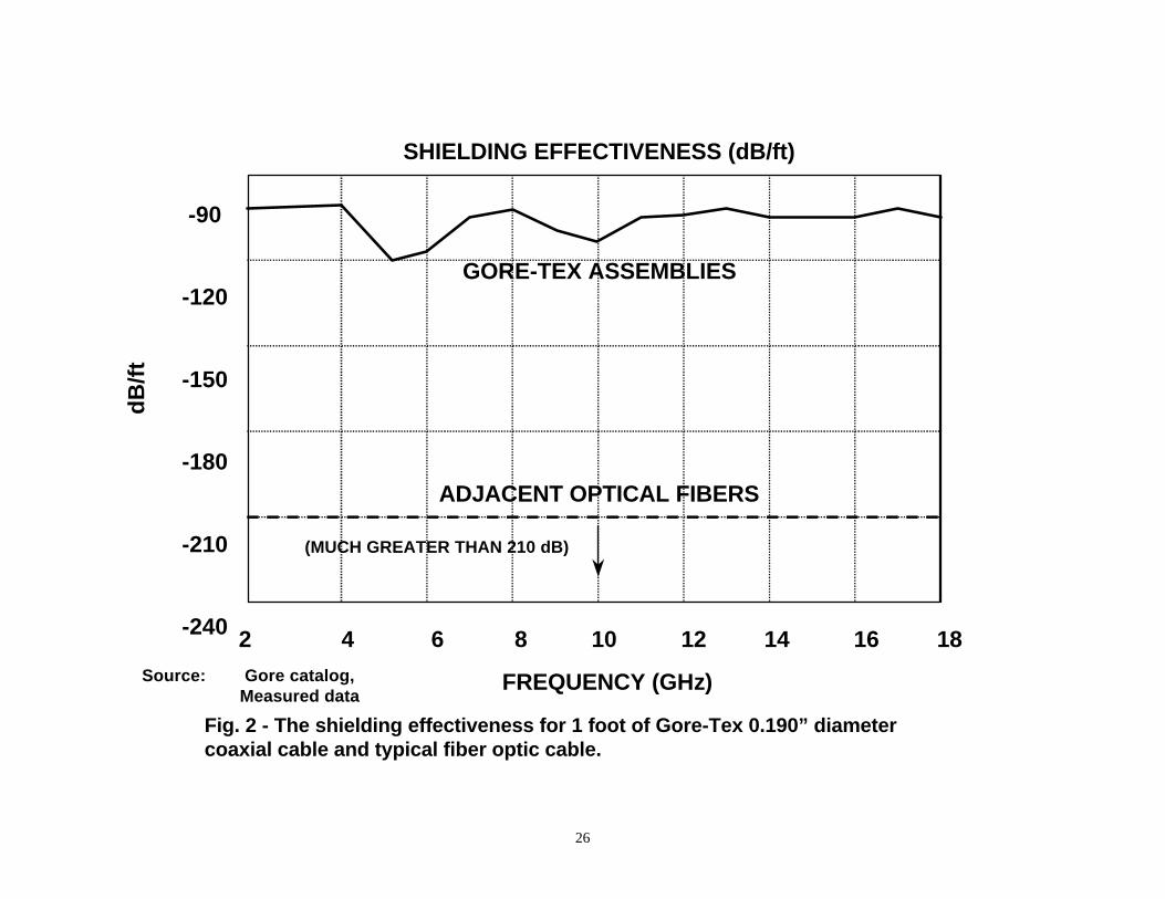
In Fig. 2 the shielding effectiveness of the cables are plotted. Fiber optic cable has virtually no pickup orradiation of EMI of RFI.
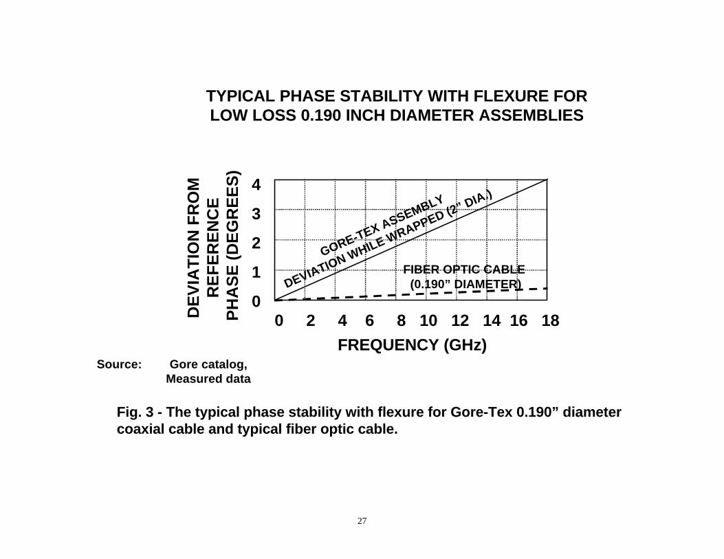
In Fig. 3 the delay change vs flexure is plotted. Delay change vs flexure for a transmission line is afunction of its diameter. The diameter of a single-mode optical fiber is normally 125 microns so itssusceptibility to delay change with flexure is much less than that of a coaxial cable with a much largerdiameter.
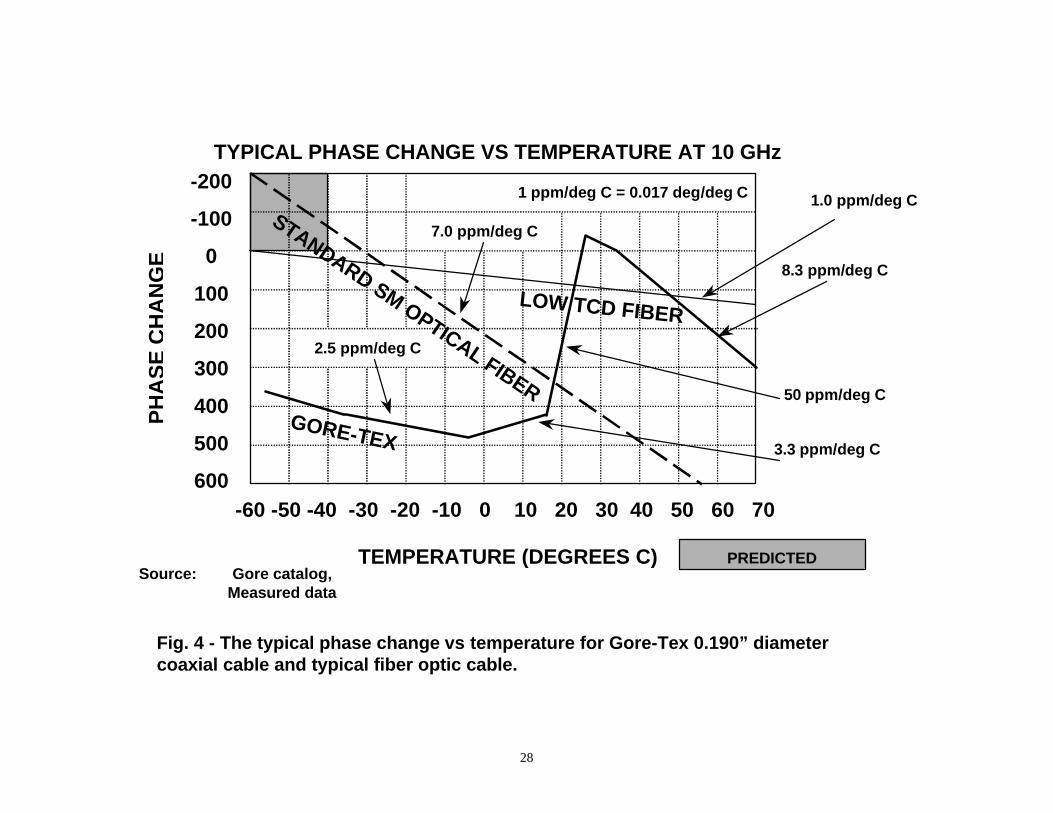
In Fig. 4 the phase change vs temperature is plotted. The delay change vs temperature in a properlyconstructed fiber optic cable is very predictable and constant.2 to 3 times better than a typical fiber optic cable. At higher temperatures it is as much as 7 times worsethan the fiber optic cable.
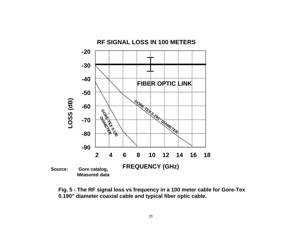
In Fig. 5 the RF loss vs frequency is plotted for a 100 meter length of cable. The loss of both 0.190”diameter and 0.290” diameter Gore-Tex coaxial cable is given to demonstrate the reduction in loss for alarger diameter coaxial cable. The loss of the fiber optic cable includes the conversion loss of the fiberoptic transmitter and receiver which is constant and is between 25 and 35 dB (as shown by the error bar).
From -60 oC to +15 oC the Gore-Tex cable is
24
The equivalent RF loss in the fiber optic cable itself is 0.08 dB in a 100 meter cable and is virtuallyconstant through this frequency range.
Another important factor for space applications is the weight of the cable. A ruggedized 0.190” diameterfiber optic cable containing two fibers weighs 5.9 kgs per 1000 feet. A Gore-Tex 0.190” diameter coaxialcable weighs 16 kgs per 1000 feet and a Gore-Tex 0.290” diameter coaxial cable weighs 36 kgs per 1000feet. The smaller Gore-Tex cable weighs 2.7 times as much as the fiber optic cable and the larger Gore-Tex cable weighs 6.1 times as much as the fiber optic cable.
An additional consideration is that active delay compensation schemes work much better in optical fiberthan they do in coaxial cables. This is because the return loss is 30 dB higher in optical fibers and opticalcomponents and the isolation of optical components such as couplers, which are required in acompensation system, is more than 70 dB higher.
7.4 Predicted Phase Variations
The cable temperature variation with time, shown in Fig. 6, was calculated by Ray Garcia for hot and coldenvironmental conditions. For about the first 30 hours in orbit the average temperature of the cable coolsdown exponentially from 300o K to as low as 242.5o K. Superimposed on this long term temperaturechange is a sinusoidal 5o K peak-to-peak variation with the frequency of the orbital period of about 1.48hours. After about 30 hours in orbit the long term temperature variation reaches steady state leaving onlythe sinusoidal 5o K peak-to-peak variation with the orbital period.
Based on this information the calculated delay variations are given in Appendix 1.
7.5 Conclusion
Fiber optic cable is obviously superior to coaxial cable in terms of change in insertion loss vs temperature,shielding effectiveness, delay change vs cable flexure, and weight. Over the temperature range from -60o
C to +15o
fiber optic cable. At higher temperatures the fiber optic cable’s thermal coefficient of delay is as much as 7times lower than the coaxial cable. The signal loss in fiber optic cable is lower than the loss in Gore-Tex0.190” diameter coaxial cable at frequencies above about 1 GHz and at 8 GHz it is as much as 60 dBlower. The Gore-Tex 0.290” diameter coaxial cable’s loss becomes larger than the loss in fiber optic cableat about 3 GHz and at 8 GHz it has as much as 30 dB higher loss.
A system study would most likely find that the weight and power consumption of a fiber optic systemwould be lower. A coaxial system would require that 20 to 50 dB more signal power would have to beapplied to the input to equal the signal level at the output of a fiber optic system.
C Gore-Tex coaxial cable has a thermal coefficient of delay which is as much as 3 times lower than
25
10
5
0
-5
-10
-15
-20
-25TY
PIC
AL
CH
AN
GE
(P
ER
CE
NT
)
-60O -40O -20O 0O 20O 40O 60O 80O
TEMPERATURE OC
TYPICAL INSERTION LOSS CHANGE VS TEMPERATURE
GORE-TEX ASSEMBLY
FIBER OPTIC CABLE ASSEMBLY
SOURCE: GORE CATALOGCORNING DATA SHEET
Fig. 1 - The change in insertion loss vs temperature for 0.190” diameter Gore-Tex coaxial cable and typical fiber optic cable.
26
-90
-120
-150
-180
-210
-240 2 4 6 8 10 12 14 16 18
SHIELDING EFFECTIVENESS (dB/ft)d
B/f
t
FREQUENCY (GHz)
ADJACENT OPTICAL FIBERS
GORE-TEX ASSEMBLIES
(MUCH GREATER THAN 210 dB)
Source: Gore catalog,Measured data
Fig. 2 - The shielding effectiveness for 1 foot of Gore-Tex 0.190” diameter coaxial cable and typical fiber optic cable.
27
4
3
2
1
00 2 4 6 8 10 12 14 16 18
FREQUENCY (GHz)
DE
VIA
TIO
N F
RO
M
RE
FE
RE
NC
E
PH
AS
E (
DE
GR
EE
S)
GORE-TEX ASSEMBLY
DEVIATION WHILE WRAPPED (2” DIA.)
TYPICAL PHASE STABILITY WITH FLEXURE FORLOW LOSS 0.190 INCH DIAMETER ASSEMBLIES
FIBER OPTIC CABLE (0.190” DIAMETER)
Source: Gore catalog,Measured data
Fig. 3 - The typical phase stability with flexure for Gore-Tex 0.190” diametercoaxial cable and typical fiber optic cable.
28
-200
-100
0
100
200
300
400
500
600-60 -50 -40 -30 -20 -10 0 10 20 30 40 50 60 70
PH
AS
E C
HA
NG
E (
PA
RT
S P
ER
MIL
LIO
N)
TEMPERATURE (DEGREES C)
TYPICAL PHASE CHANGE VS TEMPERATURE AT 10 GHz
8.3 ppm/deg C
50 ppm/deg C
3.3 ppm/deg C
2.5 ppm/deg C
GORE-TEX
STANDARD SM OPTICAL FIBER
7.0 ppm/deg C
PREDICTED
1 ppm/deg C = 0.017 deg/deg C
Source: Gore catalog,Measured data
Fig. 4 - The typical phase change vs temperature for Gore-Tex 0.190” diameter coaxial cable and typical fiber optic cable.
1.0 ppm/deg C
LOW TCD FIBER
PH
AS
E C
HA
NG
E
29
-20
-30
-40
-50
-60
-70
-80
-902 4 6 8 10 12 14 16 18
FREQUENCY (GHz)
LO
SS
(d
B)
RF SIGNAL LOSS IN 100 METERS
GO
RE-TEX 0.190
DIA
METER
FIBER OPTIC LINK
Source: Gore catalog,Measured data
Fig. 5 - The RF signal loss vs frequency in a 100 meter cable for Gore-Tex 0.190” diameter coaxial cable and typical fiber optic cable.
GORE-TEX 0.290” DIAMETER
30
8.0 New Low Profile Connectors (MT-RJ, LC, VF-45)
Just as it has been for many years in the electronics industry, integration has become the buzzword ofphotonic companies. The demand for bandwidth has fueled the need for smaller, more integrated, andpower efficient photonic system building blocks.
In 1998 six companies agreed to develop and manufacture small form factor transceivers and connectors.The connectors would be approximately half the size of the industry standard SC connector. Since nostandard for the connector receptacle was designated in the agreement, the companies developed severalcompeting designs. These designs include MT-RJ, LC, and VF-45 connectors.
Each company designed their connector to have what they conceived to be the proper tradeoffs betweenperformance, cost, reliability, and ease of use. They each hoped that their connector would be the one thatmost appealed to the end users. The marketplace will decide which design will dominate and whether ornot multiple designs will survive.
The MT-RJ has the form factor of the familiar RJ-45 wire connector used by the phone company for manyyears. This form factor is familiar to the installers of equipment and the manufacturers hope this will be afactor in making their connector popular.
A consortium designed the MT-RJ connector. The consortium members were AMP, Siecor, USConec, andFujikura. There were five design objectives:
Capitalize on proven technology,
An optical replacement for the RJ-45 phone jack,
Installer friendly,
Easily integrated with small form factor transceivers being developed by other consortiummembers, and
To be multisourced with broad industry support.
The resulting connector is duplex and is about the same size as a single fiber SC connector.
The size of SC and ST connectors limits the fiber port density to about half that of copper interfaces. Thenew MT-RJ connector would result in fiber port areas with density equal to that of copper interfaces.
The designers started with the Mini-MPO connector from AMP which uses the MT-style ferrule fromNTT. This approach would give high performance but the existing push-pull mechanism complicatedidentification of the correct orientation of the connector for installers. The latch was redesigned to operateexactly like the latch on the RJ-45.
Prior fiber optic connectors required a mating adapter to mate two plug connectors. The mating adapteraligns the ends of the two fibers to be mated. It is usually a precision sleeve that guides the connectorferrules as they are slid together and holds them in place once mated.
The MT-RJ connector contains a pre-polished fiber stub. The fiber in the cable slides into the back of theconnector and butts up against the pre-polished fiber stub which is wetted with a matching gel. Thisprovides a controlled end face finish. The fiber is held into the connector body mechanically. Thetermination procedure is simple and fast and does not require the use of epoxy or polishing.
31
Typical insertion loss for this connector is about 0.3 dB.
One of the most desirable features of this design is that the same cutouts can be used that are used for thecommon RJ-45 copper connector used by the phone companies today. This eliminates changes to themodule package which would otherwise require redesign and additional expense.
LC Connectors
Bell Laboratories engineers designed the LC connector for single and multi-mode applications. It uses a1.25 mm round ceramic ferrule. The current standard ferrule diameter used in SC, ST and otherconnectors is 2.5 mm. An adapter is available to allow equipment with a 2.5 mm diameter ferrule tointerface with the smaller ferrule.
The LC connector uses features of the RJ-45 copper connector. This provides verification that the properpolarity is maintained and there is an audible click when fully inserted. Adhesive is used to secure thefiber and assuring low loss. Installation is similar to SC and ST connectors but the time required is 40%shorter.
The dual LC connector uses two individual connectors held loosely together. This minimizes stressbecause they have some freedom of movement to compensate for relaxed tolerances. This serves tominimize losses.
The average loss of an LC connector is 0.1 dB for both single-mode and multimode connectors. For fieldinstallations the average loss is 0.2 dB. This is better than most other common connectors. The low losssupports more connectors in series for a given system loss budget.
Lucent, Methode Electronics, Molex, and Sumitomo manufacture transceivers that are compatible withthe LC connector.
The following standards recognize the LC connector:
TIA568A for areas outside of work station outlets,
ATM Forum specifications for 155 and 622 Mb/s systems,
IEEE 1394B S800 to 3200Mb/s systems, and
ISO 11801 International Cabling Standard.
VF-45 Connector
Engineers at 3M designed the VF-45 connector to give good performance at minimum cost. This designeliminates the costly ferrule used in other connectors and uses V-groove technology in its place. Theconnector is adhesive free and has a minimum number of components. Its installed cost is only about one-seventh of the cost of the industry benchmark duplex SC connector.
The VF-45 connector consists of 10 low cost injection-molded parts which are pre-assembled so that theinstaller only has to deal with 4 pieces. In contrast to this, the SC connector consists of 40 or moreprecision parts made of costly materials and using different manufacturing processes.
The socket uses a mechanical housing that clamps the fibers into the V-grooves. The plug housing clampsthe fiber so that it sticks out from the clamp and slides into the V-grooves when mated. The fibers areforced into the V-grooves at an angle so the pressure holds them in the groove and small differences in the
32
longitudinal alignment are compensated for by a change in bend radius. The loss in this connectordepends on the precision of the optical fibers being mated.
Both the plug and the socket of the VF-45 connector have integral dust covers that slide out of the waywhen the connectors are mated. When the connectors eventually have to be cleaned it can be done withoutdisassembling it. Because of greatly reduced dust and the unique construction of these connectors the lossas a function of the number of insertions is flat, even for as many as 1200 to 1500 insertions.
The design of the VF-45 connector only allows it to be inserted in the proper position so there is no risk ofthe connection being reversed. The connection is made parallel to the wall so it does not protrude and riskbeing broken off if accidentally brushed.
The VF-45 connector meets the requirements of the ISO 11801 and TIA-568A premise cabling standardsas well as the corresponding component standards (ISO/IEC, TIA/EIA). It is meant to be used onmultimode optical fiber but is being tested for compatibility with single-mode fiber.
The termination time is only two minutes per socket (two fibers) with a >98% yield. This is compared to10 or 15 minutes for more traditional connectors like the dual SC.
33
9.0 Some Typical Fiber Optic Connector Parameters
ST Connectors Multimode Loss: µ = 0.4 dB, = 0.2 dB
Fiber: 62.5/125 fiber, 0.29 numerical aperture Fiber OD, nominal: 125 µm Cable OD, nominal: 2.4 and 3.0 mm Loss Repeat: <0.2 dB per 1000 reconnects Axial Load, minimum: 35 pounds (15.9 kg)
Temperature Stability (-40°C to 75°C): ±0.2-dB maximum change Materials: Tip - Ceramic Cap - Brass, Ni plated Body - Brass, Ni plated Installation Time: One - 18 minutes Twelve - 8 minutes, average
ST Connectors SinglemodeCeramic Tip
Loss: µ = 0.35 dB, = 0.20 dB Return Loss: -42 dB average; -35 dB worst case
8.3/125 µm fiber, 0.29 numerical apertureFiber OD, nominal: 125 µm
Cable OD, nominal: 2.4 and 3.0 mm Loss Repeat: <0.2 dB per 200 reconnects Axial Load, minimum: 35 pounds (15.9 kg) Temperature Stability (-40°C to 75°C): ±0.2 dB, average change Materials: Tip - Ceramic Cap - Brass, Ni plated Body - Brass, Ni plated Installation Time: One - 18 minutes Twelve - 8 minutes, average
SC Connectors (Singlemode) Insertion Loss µ, (dB) 0.2, 0.1Return Loss (Max) -40 dB
Fiber OD, nominal 125 µm Cable OD, nominal, 3.0 mm cable, 0.9 mm buffer Loss repeatability (200 insertions) <0.2 dB Axial Load, nominal 30 lbs. Temp. Stability (-40°C to 85°C) ±0.3 dB Material Tip, Zirconia Body, Polysulfone Mount Time One, 18 minutes
34
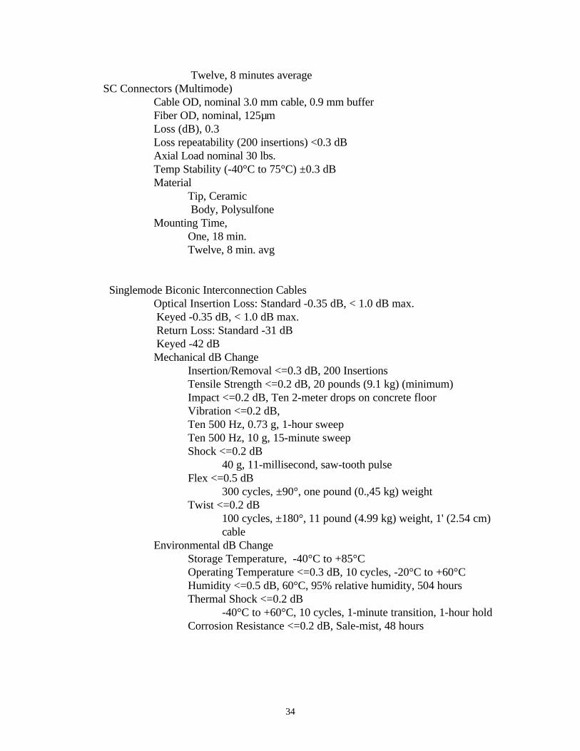
Twelve, 8 minutes average SC Connectors (Multimode)
Cable OD, nominal 3.0 mm cable, 0.9 mm buffer Fiber OD, nominal, 125µm Loss (dB), 0.3 Loss repeatability (200 insertions) <0.3 dB Axial Load nominal 30 lbs. Temp Stability (-40°C to 75°C) ±0.3 dB Material Tip, Ceramic Body, Polysulfone
Mounting Time,One, 18 min.Twelve, 8 min. avg
Singlemode Biconic Interconnection CablesOptical Insertion Loss: Standard -0.35 dB, < 1.0 dB max.
Keyed -0.35 dB, < 1.0 dB max. Return Loss: Standard -31 dB Keyed -42 dB Mechanical dB Change
Insertion/Removal <=0.3 dB, 200 Insertions Tensile Strength <=0.2 dB, 20 pounds (9.1 kg) (minimum) Impact <=0.2 dB, Ten 2-meter drops on concrete floor Vibration <=0.2 dB,
Ten 500 Hz, 0.73 g, 1-hour sweepTen 500 Hz, 10 g, 15-minute sweep
Shock <=0.2 dB 40 g, 11-millisecond, saw-tooth pulse Flex <=0.5 dB 300 cycles, ±90°, one pound (0.,45 kg) weight Twist <=0.2 dB
100 cycles, ±180°, 11 pound (4.99 kg) weight, 1' (2.54 cm)cable
Environmental dB Change Storage Temperature, -40°C to +85°C
Operating Temperature <=0.3 dB, 10 cycles, -20°C to +60°C Humidity <=0.5 dB, 60°C, 95% relative humidity, 504 hours Thermal Shock <=0.2 dB -40°C to +60°C, 10 cycles, 1-minute transition, 1-hour hold Corrosion Resistance <=0.2 dB, Sale-mist, 48 hours
35
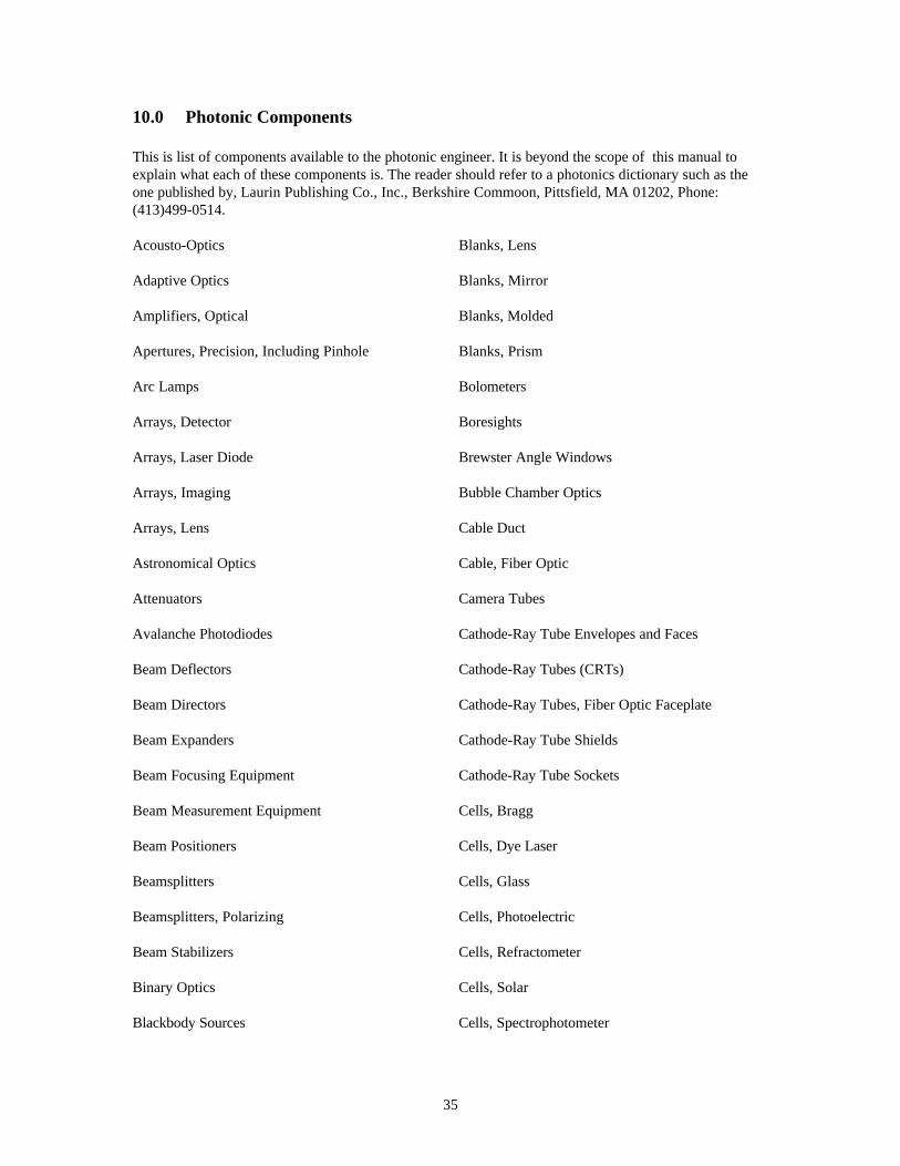
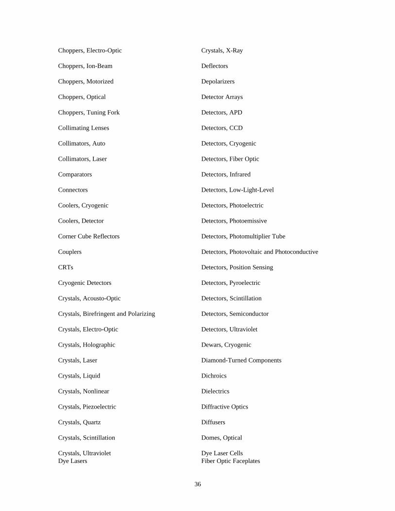
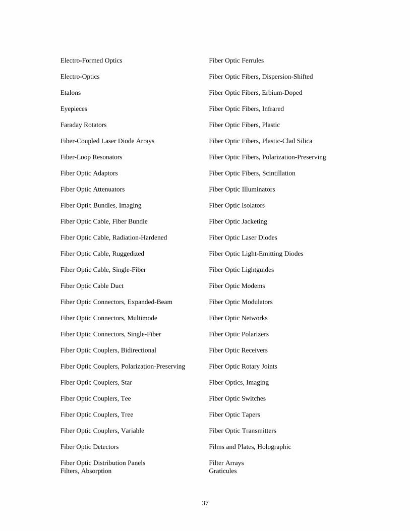
10.0 Photonic Components
This is list of components available to the photonic engineer. It is beyond the scope of this manual toexplain what each of these components is. The reader should refer to a photonics dictionary such as theone published by, Laurin Publishing Co., Inc., Berkshire Commoon, Pittsfield, MA 01202, Phone:(413)499-0514.
Acousto-Optics
Adaptive Optics
Amplifiers, Optical
Apertures, Precision, Including Pinhole
Arc Lamps
Arrays, Detector
Arrays, Laser Diode
Arrays, Imaging
Arrays, Lens
Astronomical Optics
Attenuators
Avalanche Photodiodes
Beam Deflectors
Beam Directors
Beam Expanders
Beam Focusing Equipment
Beam Measurement Equipment
Beam Positioners
Beamsplitters
Beamsplitters, Polarizing
Beam Stabilizers
Binary Optics
Blackbody Sources
Blanks, Lens
Blanks, Mirror
Blanks, Molded
Blanks, Prism
Bolometers
Boresights
Brewster Angle Windows
Bubble Chamber Optics
Cable Duct
Cable, Fiber Optic
Camera Tubes
Cathode-Ray Tube Envelopes and Faces
Cathode-Ray Tubes (CRTs)
Cathode-Ray Tubes, Fiber Optic Faceplate
Cathode-Ray Tube Shields
Cathode-Ray Tube Sockets
Cells, Bragg
Cells, Dye Laser
Cells, Glass
Cells, Photoelectric
Cells, Refractometer
Cells, Solar
Cells, Spectrophotometer
36
Choppers, Electro-Optic
Choppers, Ion-Beam
Choppers, Motorized
Choppers, Optical
Choppers, Tuning Fork
Collimating Lenses
Collimators, Auto
Collimators, Laser
Comparators
Connectors
Coolers, Cryogenic
Coolers, Detector
Corner Cube Reflectors
Couplers
CRTs
Cryogenic Detectors
Crystals, Acousto-Optic
Crystals, Birefringent and Polarizing
Crystals, Electro-Optic
Crystals, Holographic
Crystals, Laser
Crystals, Liquid
Crystals, Nonlinear
Crystals, Piezoelectric
Crystals, Quartz
Crystals, Scintillation
Crystals, UltravioletDye Lasers
Crystals, X-Ray
Deflectors
Depolarizers
Detector Arrays
Detectors, APD
Detectors, CCD
Detectors, Cryogenic
Detectors, Fiber Optic
Detectors, Infrared
Detectors, Low-Light-Level
Detectors, Photoelectric
Detectors, Photoemissive
Detectors, Photomultiplier Tube
Detectors, Photovoltaic and Photoconductive
Detectors, Position Sensing
Detectors, Pyroelectric
Detectors, Scintillation
Detectors, Semiconductor
Detectors, Ultraviolet
Dewars, Cryogenic
Diamond-Turned Components
Dichroics
Dielectrics
Diffractive Optics
Diffusers
Domes, Optical
Dye Laser CellsFiber Optic Faceplates
37
Electro-Formed Optics
Electro-Optics
Etalons
Eyepieces
Faraday Rotators
Fiber-Coupled Laser Diode Arrays
Fiber-Loop Resonators
Fiber Optic Adaptors
Fiber Optic Attenuators
Fiber Optic Bundles, Imaging
Fiber Optic Cable, Fiber Bundle
Fiber Optic Cable, Radiation-Hardened
Fiber Optic Cable, Ruggedized
Fiber Optic Cable, Single-Fiber
Fiber Optic Cable Duct
Fiber Optic Connectors, Expanded-Beam
Fiber Optic Connectors, Multimode
Fiber Optic Connectors, Single-Fiber
Fiber Optic Couplers, Bidirectional
Fiber Optic Couplers, Polarization-Preserving
Fiber Optic Couplers, Star
Fiber Optic Couplers, Tee
Fiber Optic Couplers, Tree
Fiber Optic Couplers, Variable
Fiber Optic Detectors
Fiber Optic Distribution PanelsFilters, Absorption
Fiber Optic Ferrules
Fiber Optic Fibers, Dispersion-Shifted
Fiber Optic Fibers, Erbium-Doped
Fiber Optic Fibers, Infrared
Fiber Optic Fibers, Plastic
Fiber Optic Fibers, Plastic-Clad Silica
Fiber Optic Fibers, Polarization-Preserving
Fiber Optic Fibers, Scintillation
Fiber Optic Illuminators
Fiber Optic Isolators
Fiber Optic Jacketing
Fiber Optic Laser Diodes
Fiber Optic Light-Emitting Diodes
Fiber Optic Lightguides
Fiber Optic Modems
Fiber Optic Modulators
Fiber Optic Networks
Fiber Optic Polarizers
Fiber Optic Receivers
Fiber Optic Rotary Joints
Fiber Optics, Imaging
Fiber Optic Switches
Fiber Optic Tapers
Fiber Optic Transmitters
Films and Plates, Holographic
Filter ArraysGraticules
38
Filters, Acousto-Optic
Filters, Birefringent
Filters, Broadband
Filters, Colored Glass
Filters, Contrast Enhancement
Filters, Dichroic
Filters, Diffractive
Filters, Holographic
Filters, Interference
Filters, Laser Line
Filters, Laser Protective
Filters, Neutral Density
Filters, Photographic
Filters, Pinhole
Filters, Plastic
Filters, Polarizing
Filters, Rejection Band
Filters, Spatial
Filters, Tunable
Filters, Wedge
Filters, X-Ray
Flats, Optical
Fourier Optics
Fresnel Optics
Glass-To-Metal Seals
Glass TubingLaser Q-Switches
Laser Rods
Gratings, Blazed
Gratings, Diffraction
Gratings, Echelon
Gratings, Holographic
Gratings, Laser
Gratings, Radial
Gratings, Replica
Gratings, Ronchi
Halogen Light Sources
Holograms
Holographic Films and Plates
Holographic Filters
Holographic Gratings
Illuminators
Image Sensors, Area
Image Sensors, Linear
Imaging Arrays
Infrared Sources
Interferometer Accessories
Irises
Kerr Cells
Laser Diode Arrays
Laser Diode Collimating Lenses
Laser Diode Modules
Laser Diodes
Laser ModelockersLenses, Plastic
Lenses, Precision Glass Balls
39
Laser-to-Fiber Couplers
LEDs
Lens Arrays
Lens Blanks
Lenses, Achromatic
Lenses, Anamorphic
Lenses, Aspheric
Lenses, Catadioptric
Lenses, Complex
Lenses, Condenser
Lenses, Conical
Lenses, Cylindrical
Lenses, Diamond-Turned
Lenses, Diffraction-Limited
Lenses, Diffractive
Lenses, Eyepieces
Lenses, Fourier
Lenses, Fresnel
Lenses, GRIN
Lenses, Laser
Lenses, Laser Diode Collimating
Lenses, Microscope
Lenses, Miniature
Lenses, Molded
Lenses, MonochromaticLight Sources, Miniature
Light Sources, Plasma Discharge
Lenses, Prismatic
Lenses, Projection
Lenses, Radiation Resistant
Lenses, Relay
Lenses, Sapphire
Lenses, Simple
Lenses, Spheric
Lenses, Telephoto
Lenses, Telescope
Lenses, Wide Angle
Lenses, Zoom, Variable Focal Length
Light-Emitting Diodes, Infrared
Light-Emitting Diodes, Visible
Light Shields
Light Sources, Calibrated
Light Sources, Coherent
Light Sources, Fluorescent
Light Sources, Glow Discharge
Light Sources, Halogen
Light Sources, Hollow Cathode
Light Sources, Incandescent
Light Sources, Infrared
Light Sources, Krypton
Light Sources, Laser Diode
Light Sources, MercuryMirrors, Spherical
Mirrors, Ultraviolet
40
Light Sources, Stroboscopic
Light Sources, Tungsten
Light Sources, Ultraviolet
Light Sources, VUV
Light Sources, Xenon
Liquid Crystal Light Valves
Magneto-Optics
Metal Optics
Micro-Optics
Microscope Eyepieces
Microscope Objectives
Mirror Blanks
Mirrors, Aspheric
Mirrors, Astronomical
Mirrors, Beamsplitting
Mirrors, Cold
Mirrors, Concave and Convex, Spherical
Mirrors, Diamond-Turned
Mirrors, Fabry-Perot Etalon
Mirrors, Flat
Mirrors, Laser
Mirrors, Metal
Mirrors, Partial
Mirrors, Pellicle
Mirrors, PolygonalPhototransistors
Pinholes
Plastic Fibers
Mirrors, X-Ray
Modelockers, Laser
Modulators, Acousto-Optic
Modulators, Electro-Optic
Modulators, Fiber Optic
Modulators, Magneto-Optic
Modulators, Mechanical
Modulators, Photoelastic
Modulators, Spatial Light
Mounts, Laser
Mounts, Optical
Mounts, Sidereal
Mounts, Telescope
Mounts, Tripods
Mounts, Vibration-Isolated
Optical Couplers
Optical Delay Lines
Optical Fibers
Optical Isolators
Optical Mounts
Optoisolators
Partial Reflectors
Pellicles, Optical
Photodetectors
PhotodiodesSensor Cards
Shutters, Laser
Shutters, Manual
41
Plastic Optics
Pockels Cells
Polarizers, Fiber Optic
Polarizers, Infrared
Polarizers, Visible
Polarizing Beamsplitters
Polarizing Prisms
Prism Blanks
Prism Couplers
Prisms, Nonpolarizing
Q-Switches
Reflectors, Corner Cube
Reflectors, Partial
Reticles
Retroreflectors
Rotary Joints
Rotators, Faraday
Rulings, Precision Scale
Rulings, Ronchi (See Gratings)
Screens, Front Projection
Screens, Lenticular
Screens, Projection Television
Screens, Rear Projection
Screens, Translucent
Shutters, Optical
Sidereal Mounts
Tubing, Glass
Wave Plates
Wave Plates, Infrared
Wedges, Optical
Windows, Brewster Angle
Windows, Diamond
Windows, Infrared
Windows, Sapphire
YAG
YLF
42
11.0 Photonic Component and System Manufacturers
This is a list of the better known photonic manufacturers with addresses and phone numbers and some ofthe parts they manufacture. It should provide a starting place for searching for a particular photonic part.
43
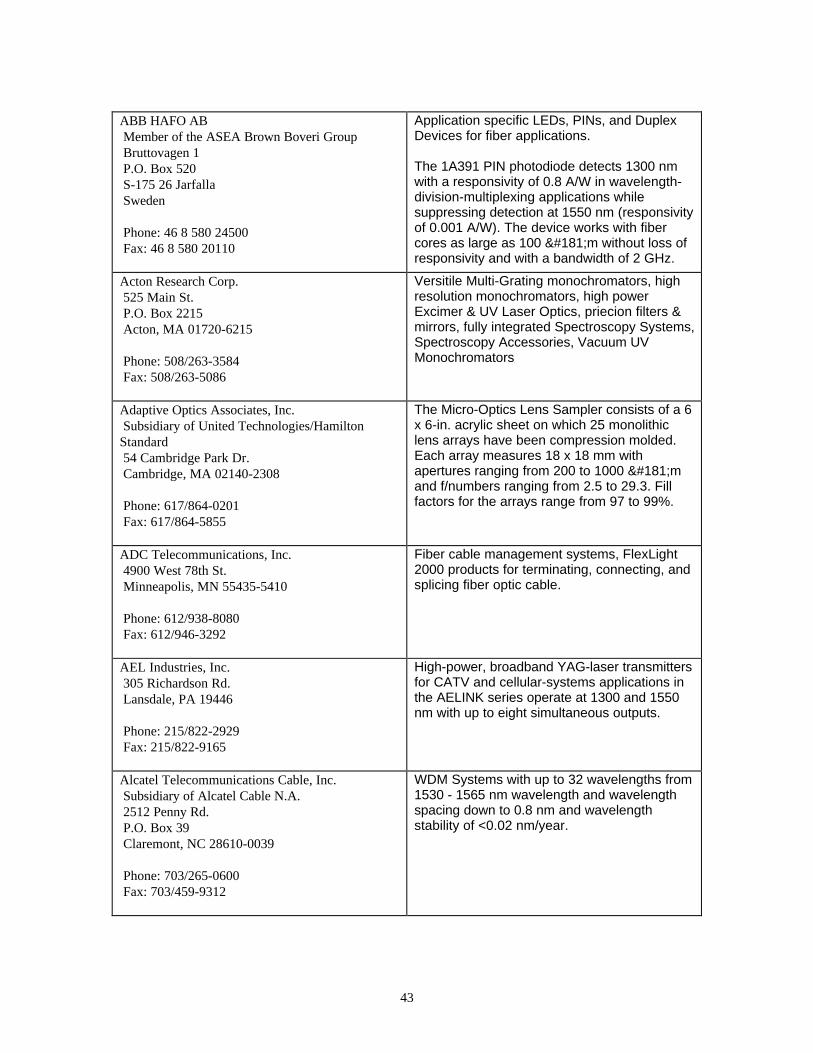
ABB HAFO AB Member of the ASEA Brown Boveri Group Bruttovagen 1 P.O. Box 520 S-175 26 Jarfalla Sweden
Phone: 46 8 580 24500 Fax: 46 8 580 20110
Application specific LEDs, PINs, and DuplexDevices for fiber applications.
The 1A391 PIN photodiode detects 1300 nmwith a responsivity of 0.8 A/W in wavelength-division-multiplexing applications whilesuppressing detection at 1550 nm (responsivityof 0.001 A/W). The device works with fibercores as large as 100 µm without loss ofresponsivity and with a bandwidth of 2 GHz.
Acton Research Corp. 525 Main St. P.O. Box 2215 Acton, MA 01720-6215
Phone: 508/263-3584 Fax: 508/263-5086
Versitile Multi-Grating monochromators, highresolution monochromators, high powerExcimer & UV Laser Optics, priecion filters &mirrors, fully integrated Spectroscopy Systems,Spectroscopy Accessories, Vacuum UVMonochromators
Adaptive Optics Associates, Inc. Subsidiary of United Technologies/HamiltonStandard 54 Cambridge Park Dr. Cambridge, MA 02140-2308
Phone: 617/864-0201 Fax: 617/864-5855
The Micro-Optics Lens Sampler consists of a 6x 6-in. acrylic sheet on which 25 monolithiclens arrays have been compression molded.Each array measures 18 x 18 mm withapertures ranging from 200 to 1000 µmand f/numbers ranging from 2.5 to 29.3. Fillfactors for the arrays range from 97 to 99%.
ADC Telecommunications, Inc. 4900 West 78th St. Minneapolis, MN 55435-5410
Phone: 612/938-8080 Fax: 612/946-3292
Fiber cable management systems, FlexLight2000 products for terminating, connecting, andsplicing fiber optic cable.
AEL Industries, Inc. 305 Richardson Rd. Lansdale, PA 19446
Phone: 215/822-2929 Fax: 215/822-9165
High-power, broadband YAG-laser transmittersfor CATV and cellular-systems applications inthe AELINK series operate at 1300 and 1550nm with up to eight simultaneous outputs.
Alcatel Telecommunications Cable, Inc. Subsidiary of Alcatel Cable N.A. 2512 Penny Rd. P.O. Box 39 Claremont, NC 28610-0039
Phone: 703/265-0600 Fax: 703/459-9312
WDM Systems with up to 32 wavelengths from1530 - 1565 nm wavelength and wavelengthspacing down to 0.8 nm and wavelengthstability of <0.02 nm/year.
44
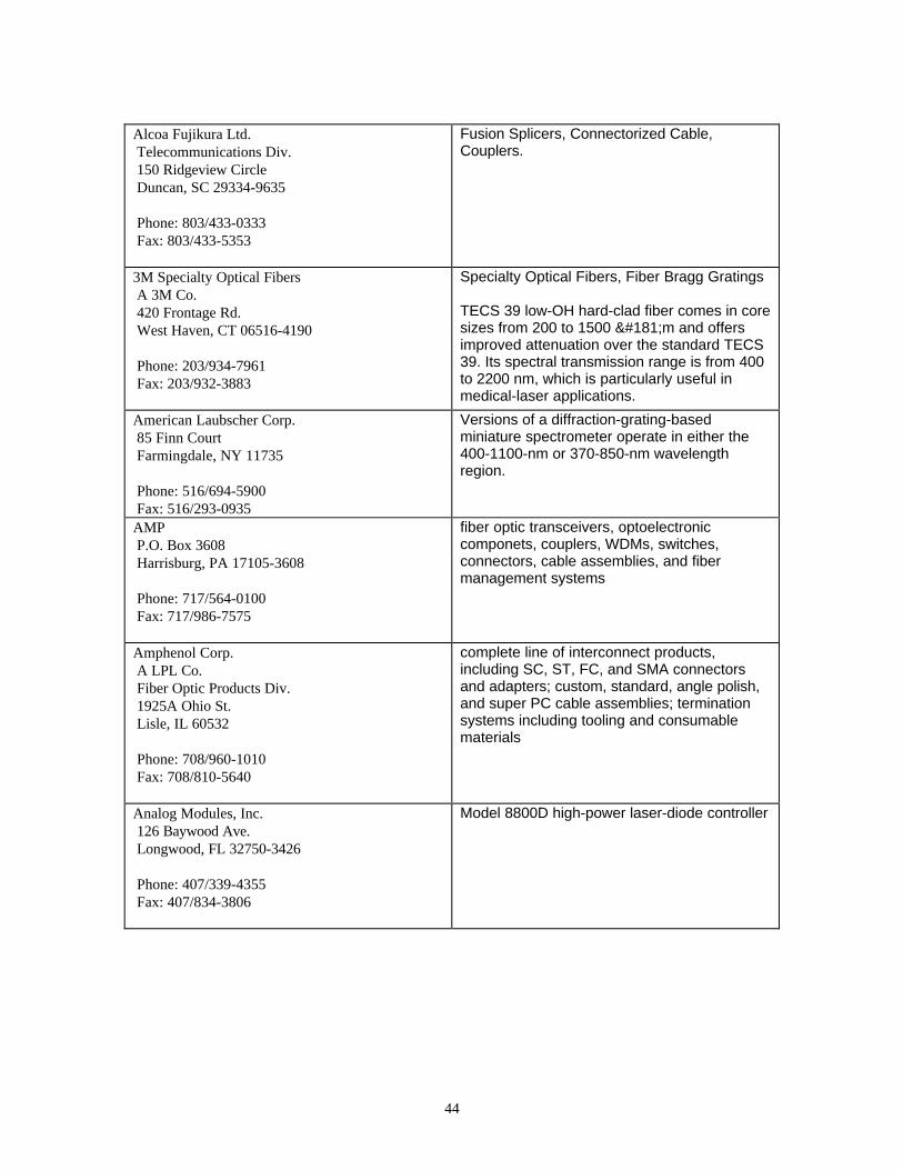
Alcoa Fujikura Ltd. Telecommunications Div. 150 Ridgeview Circle Duncan, SC 29334-9635
Phone: 803/433-0333 Fax: 803/433-5353
Fusion Splicers, Connectorized Cable,Couplers.
3M Specialty Optical Fibers A 3M Co. 420 Frontage Rd. West Haven, CT 06516-4190
Phone: 203/934-7961 Fax: 203/932-3883
Specialty Optical Fibers, Fiber Bragg Gratings
TECS 39 low-OH hard-clad fiber comes in coresizes from 200 to 1500 µm and offersimproved attenuation over the standard TECS39. Its spectral transmission range is from 400to 2200 nm, which is particularly useful inmedical-laser applications.
American Laubscher Corp. 85 Finn Court Farmingdale, NY 11735
Phone: 516/694-5900 Fax: 516/293-0935
Versions of a diffraction-grating-basedminiature spectrometer operate in either the400-1100-nm or 370-850-nm wavelengthregion.
AMP P.O. Box 3608 Harrisburg, PA 17105-3608
Phone: 717/564-0100 Fax: 717/986-7575
fiber optic transceivers, optoelectroniccomponets, couplers, WDMs, switches,connectors, cable assemblies, and fibermanagement systems
Amphenol Corp. A LPL Co. Fiber Optic Products Div. 1925A Ohio St. Lisle, IL 60532
Phone: 708/960-1010 Fax: 708/810-5640
complete line of interconnect products,including SC, ST, FC, and SMA connectorsand adapters; custom, standard, angle polish,and super PC cable assemblies; terminationsystems including tooling and consumablematerials
Analog Modules, Inc. 126 Baywood Ave. Longwood, FL 32750-3426
Phone: 407/339-4355 Fax: 407/834-3806
Model 8800D high-power laser-diode controller
45
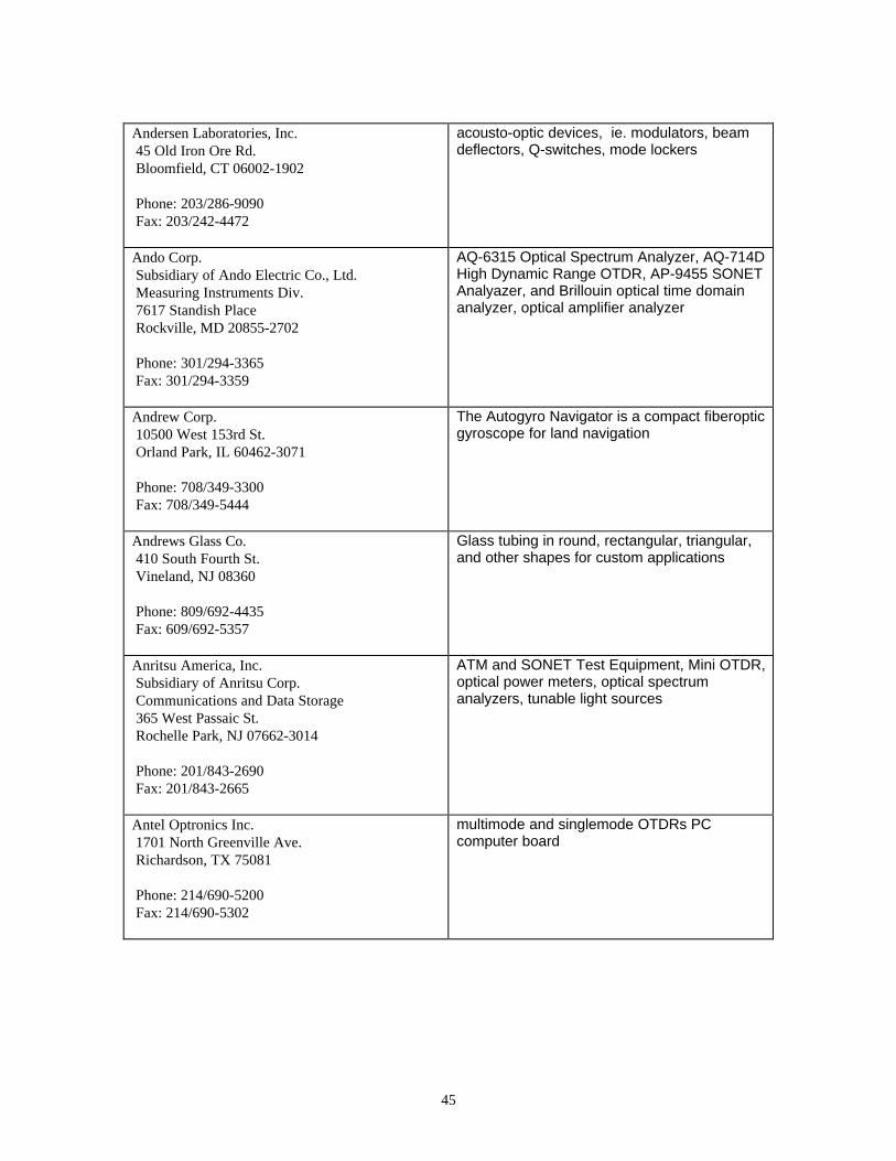
Andersen Laboratories, Inc. 45 Old Iron Ore Rd. Bloomfield, CT 06002-1902
Phone: 203/286-9090 Fax: 203/242-4472
acousto-optic devices, ie. modulators, beamdeflectors, Q-switches, mode lockers
Ando Corp. Subsidiary of Ando Electric Co., Ltd. Measuring Instruments Div. 7617 Standish Place Rockville, MD 20855-2702
Phone: 301/294-3365 Fax: 301/294-3359
AQ-6315 Optical Spectrum Analyzer, AQ-714DHigh Dynamic Range OTDR, AP-9455 SONETAnalyazer, and Brillouin optical time domainanalyzer, optical amplifier analyzer
Andrew Corp. 10500 West 153rd St. Orland Park, IL 60462-3071
Phone: 708/349-3300 Fax: 708/349-5444
The Autogyro Navigator is a compact fiberopticgyroscope for land navigation
Andrews Glass Co. 410 South Fourth St. Vineland, NJ 08360
Phone: 809/692-4435 Fax: 609/692-5357
Glass tubing in round, rectangular, triangular,and other shapes for custom applications
Anritsu America, Inc. Subsidiary of Anritsu Corp. Communications and Data Storage 365 West Passaic St. Rochelle Park, NJ 07662-3014
Phone: 201/843-2690 Fax: 201/843-2665
ATM and SONET Test Equipment, Mini OTDR,optical power meters, optical spectrumanalyzers, tunable light sources
Antel Optronics Inc. 1701 North Greenville Ave. Richardson, TX 75081
Phone: 214/690-5200 Fax: 214/690-5302
multimode and singlemode OTDRs PCcomputer board
46
AOFR Americas, Inc. A BHP Co. 800 East Campbell Rd., Ste. 108 Richardson, TX 75081
Phone: 214/644-1394 Fax: 214/480-9278
single-mode and multimode optical couplers
wavelength division multiplexers
AOTF Technology, Inc. 540-6 Weddell Dr. Sunnyvale, CA 94089
Phone: 408/734-5435 Fax: 408/734-0514
acouto-optic devices, sub-systems, andsystems
Applied Laser Systems 2160 NW Vine St. Grants Pass, OR 97526
Phone: 503/479-0484 Fax: 503/476-5105
Clarity Lenses provide miniature, anamorphic,and astigmatic correcting lenses for visiblediode lasers to produce a round Gaussianbeam.
Applied Optronics Corp. 111 Corporate Blvd., Bldg. J South Plainfield, NJ 07080
Phone: 908/753-6300 Fax: 908/753-4041
Fiber-coupled visible laser diodes provide achoice of two photosensitizer wavelengths forresearch in photodynamic therapy and otherapplications.
AstroCam Ltd. Innovation Centre, Milton Rd. Cambridge Science Pk Cambridge CB4 4GS England
Phone: 44 1223 420705 Fax: 44 1223 423021
Back-illuminated CCDs, highly sensitive in blueand UV
AT&T Microelectronics Subsidiary of AT&T Dept. 500404000 555 Union Blvd. Allentown, PA 18103-1229
Phone: 800/372-2447
fiber optic communications equipment,including couplers, connectors, cables, and testequipment
47
Atramet Inc. 222 Sherwood Ave. Farmingdale, NY 11735-1718
Phone: 516/694-9000 Fax: 516/694-9177
Russian-made Ti:sapphire rods are available indiameters ranging from 3 to 8 mm and inlengths up to 150 mm.
Augat Photon Subsidiary of Augat, Inc. 7725 Lougheed Hgwy. Burnaby, B.C. V5A 4V8 Canada
Phone: 604/420-8733 Fax: 604/420-9606
Fiber optic connectors, adaptors, cableassemblies, and fiber optic distributioinenclosures
Big Sky Laser Technologies, Inc. P.O. Box 8100 Bozeman, MT 59715-2001
Phone: 406/586-0131
Supplier of compact, rugged solid-state lasers andsubassemblies.
Brimrose Corp. of America 5020 Campbell Blvd. Baltimore, MD 21236
Phone: 410/931-7200 Fax: 410/931-7206
custom acousto-optic tunable filters (AOTF),acousto-optic modulators and scanners, RFdriver, mercury manganese telluride-infrareddetectors
Broadband Communications Products, Inc. 305 East Dr., Ste. A Melbourne, FL 32904
Phone: 407/984-3671 Fax: 407/728-0487
High speed analog and digital fiber optic links
Burleigh Instruments, Inc. Burleigh Park P.O. Box E Fishers, NY 14453-0755
Phone: 716/924-9355 Fax: 716/924-9072
The WA-1500 Wavemeter uses provenMichelson interferometer-based technology.
Inchworm Nanopositioning Systems,Nanometer resolution
48
Deutsch Ltd. Subsidiary of Deutsch Corp. Birches Ind. Estate East Grinstead, West Sussex RH19 1RW England
Phone: 44 1342 410033 Fax: 44 1342 410005
FAST HRL OPTOCLIP connector, expandedbeam, CONIX simplex and duplex
custom and standard SC, ST, FC, SMA, FSD,and ESCON connectors
CASIX P.O. Box 1103 Fuzhou, Fujian 350014 China
Phone: 86 591 366 6957 Fax: 86 591 362 1248
acousto-optic materials
Centronic Inc. E-O Div. 2088 Anchor Court Newbury Park, CA 91320
Phone: 805/499-5902 Fax: 805/499-7770
The BPW-34FR silicon photodiode
The OSD100-5TBNC silicon photodiode offersenhanced spectral response at bluewavelengths
Corning Incorporated Opto-Electronics Group MP-RO-02 Corning, NY 14831
Phone: Fax: 607/974-7522
Polarcor polarizers, 40 dB contrast ratio,temperatures up to 400 degrees C, 99 %transmittance, acceptance angles in excess of30 degrees,
Crystal Technology, Inc. A Siemens Co. 1040 East Meadow Circle Palo Alto, CA 94303
Phone: 415/856-7911 Fax: 415/858-0944
acousto-optic crystals and components,electro-optics, nonlinear optics, integratedoptics,
AO deflectors, modulators, and Q-switches:EO Q-switches, IO modulators and switches,fabricated crystals of lithium niobate, lithiumtantalate, TeO(2), KTP and BBO
CVI Laser Corp. 200 Dorado Place SE P.O. Box 11308 Albuquerque, NM 87192
Phone: 505/296-9541 Fax: 505/298-9908
Optical coatings, laser optics, optical mounts,waveplates (zero order, mulriple order, dualwavelength, single order mica, ahromatic,rotary mounts)
49
Deutsch Ltd. Subsidiary of Deutsch Corp. Birches Ind. Estate East Grinstead, West Sussex RH19 1RW England
Phone: 44 1342 410033 Fax: 44 1342 410005
Conix Duplexers permit bi-directionaltransmission over a fiber.
Diamond USA Inc. 119 Russell St. Littleton, MA 01460
Phone: 508/952-0164 Fax: 508/952-0166
Precision fiber optic connectors.
Diamonex, Inc. 7150 Windsor Dr. Allentown, PA 18106-9328
Phone: 610/366-7100 Fax: 610/366-7111
Diamond heat sinks with thermal conductivityof more than 1300 W/mK
DiCon Fiberoptics, Inc. 1331 Eighth St. Berkeley, CA 94710
Phone: 510/528-0427 Fax: 510/528-1519
Switches, WDMs, Bandpass Filters, (fixed andtuneable)
E-TEK Dynamics, Inc. 1885 Lundy Ave., #103 P.O. Box 611120 San Jose, CA 95131
Phone: 408/432-6300 Fax: 408/432-8550
fiber opotic isolators, couplers, WDMs,electrooptic modulators, tuneable lasersources, laser diode test system
Eastman Kodak Co. Commercial and Government Systems 1447 St. Paul St. Rochester, NY 14653-7006
Phone: 716/253-6685 Fax: 716/253-6988
high performance 1024 X 1024 pixel, full framecharge coupled device image sensor
50
Edmund Scientific Co. 101 East Gloucester Pike Barrington, NJ 08007
Phone: 609/547-3488 Fax: 609/573-6295
Optics ie. Lenses, prisms, etc.
EG&G Ltd. Subsidiary of EG&G, Inc. EG&G Fiber Optics Div. Mulberry Business Park Sorbus House Wokingham, Berks RG11 2GY England
Phone: 44 734 773003 Fax: 44 734 773493
complete range of pulsed and CW high powerlaser diodes, together with silicon and InGaAsp-i-n and APD detectors
Electrophysics Corp. 373 Route 46, Bldg. E Fairfield, NJ 07004-2442
Phone: 201/882-0211 Fax: 201/882-0997
Infrared viewers 0.7 to 1.3 um +.
EPITAXX Optoelectronic Devices, Inc. Subsidiary of Nippon Sheet Glass Co., Ltd. 7 Graphics Dr. West Trenton, NJ 08628
Phone: 609/538-1800 Fax: 609/538-1684
The ETXXXXGR-TE series features 100-, 500-and 1000 um InGaAs graded photodiode
The ETXXXXGR-TE series features 100-, 500-and 1000 um InGaAs graded photodiode
Epoxy Technology, Inc. 14 Fortune Dr. Billerica, MA 01821
Phone: 508/667-3805 (Inside MA) 800/227-2201 (Outside MA) 800/227-2201
Fax: 508/663-9782
Epoxies and polymers for optics and fiberoptics including fiber optic pigtailing, protectivecoatings, recladding PCS optical fibers, pottingand casting components
Evaporated Coatings, Inc. 2365 Maryland Rd. Willow Grove, PA 19090
Phone: 215/659-3080 Fax: 215/659-1275
custom manufacturer of thin vacuum depositedthin films for fiber optic components, glass,metal, and plastic substrates. coatings includeoptical filters, mirrors, beamsplitters, anti-reflection, and index matching designs.
51
EXFO Electro-Optical Engineering, Inc. 465 Godin Ave. Vanier, P.Q. G1M 3G7 Canada
Phone: 418/683-0211 (Inside P.Q.) 800/663-EXFO
Fax: 418/683-2170
Fiber optic test equipment.
Fermionics Corp. 4555 Runway St. Simi Valley, CA 93063
Phone: 805/582-0155 Fax: 805/582-1623
InGaAs linear array chip
Fiber Instrument Sales, Inc. 161 Clear Rd. Oriskany, NY 13424
Phone: 315/736-2206 (Outside NY) 800/445-2901
Fax: 315/736-2285
Patchcord Attenuator
Power Meter
A full line of fiber optic products.
FJW Optical Systems, Inc. 629 South Vermont St. Palatine, IL 60067
Phone: 708/358-2500 Fax: 708/358-2533
Find-R-Scope IR viewer
Fotec, Inc. 151 Mystic Ave. Medford, MA 02155-4615
Phone: 617/396-6155 Fax: 617/396-6395
FO tracer is a visible light source used to testfiberoptic cables for continuity
GEC Advanced Optical Products Subsidiary of GEC Marconi Research Centre West Hanning Field Rd. Great Baddow Chelmsford, Essex CM2 8HN England
Phone: 44 1245 473331 Fax: 44 1245 475244
Photoreceiver for broadband analog linksoperates at 1.3 and 1.55 um.
52
Gould Electronics Inc. Fiber Optics Div. 1121 Benfield Blvd. Millersville, MD 21108-2540
Phone: 410/987-5600 Fax: 410/987-1201
Fiberoptic planar waveguide splitters areavailable with split counts from two to 32.
Hamamatsu Corp. Subsidiary of Photonic Management Corp. 360 Foothill Rd. P.O. Box 6910 Bridgewater, NJ 08807-6910
Phone: 908/231-0960 (Outside NJ) 800/524-0504
Fax: 908/231-1218
microchannel-plate photomultiplier tube
Hewlett-Packard Co. Microwave Technology Div. Lightwave Operation 1400 Fountaingrove Pkwy. 1USF Santa Rosa, CA 95403 Phone: 800/452-4844 Fax: 707/577-5221
Fiber optic components for SONET, HPPI, andFDDI.
ILX Lightwave Corp. 31950 East Frontage Rd. P.O. Box 6310 Bozeman, MT 59771-6310 Phone: 406/586-1244 (Inside MT) 800/459-9459 (Outside MT) 800/459-9459 Fax: 406/586-9405
laser-diode drivers
Innovative Fibers 11 Larcher P.O. Box 84148 Gatineau, P.Q. J8P 7R8 Canada Phone: 819/663-4795 Fax: 819/663-4973
Bragg gratiing experts
Selective Filters for WDM, Optical Sensors,Amplifier Noise Reduction, and In-fiber lasers.
Integrated Optical Components Ltd. 3 Waterside Park Eastways Witham, Essex CM8 3YQ England
Phone: 44 1376 502110 Fax: 44 1376 502125
LiNbO integrated optics ie. modulators with lowdrive voltage,
53
Janos Technology, Inc. Route 35 HCR #33, Box 25 Townshend, VT 05353-7702
Phone: 802/365-7714 Fax: 802/365-4596
For applications that require nonimagingenergy collection, integrated packages that usecompound parabolic concentrators areavailable.
JDS Fitel Inc. 570 West Hunt Club Rd. Nepean, On. K2G 5W8 Canada
Phone: 613/727-1303 Fax: 613/727-8284
high-power diode-laser modules
Kyocera Industrial Ceramics Corp. Subsidiary of Kyocera International, Inc. Electro-Optics Div. 100 Randolph Rd. Somerset, NJ 08875-6700
Phone: 908/560-3666 Fax: 908/627-9594
ceramic ferrules, split sleeves, tubes, SC, FC,and D4 connectors, adapters, recepticles,optical couplers, WDM, WIC, isolators,LiNbO3, aspherical lens, saphire ball lens,lenses and optical fiber, hermetic lasaerpackages, heat sinks, and laser submounts
Laser Armor Tech Corp. Member of the Cook Group Inc. 10575 Roselle St. San Diego, CA 92121
Phone: 619/453-0670 Fax: 619/453-2638
Form metal tubes around optical fibers.
Laser Diode, Inc. Member of the Morgan Crucible Group plc 4 Olsen Ave. Edison, NJ 08820
Phone: 908/549-9001 Fax: 908/906-1559
lasers, LEDs, super radiant diode emmitters,pin detectors, high sensitivity pinfet receivers,RF and video links
Lasertron 37 North Ave. Burlington, MA 01803-3305
Phone: 617/272-6462Fax: 617/273-2694
Microwave fiber optic transmitters and receivers.
54
Lucent Technologies555 Union Blvd. Rm. 21Q133BA, Dept. P83Allentown, PA 18103Phone: 800-372-24447FAX: 610-712-4106
Lasers with built-in modulators. Model 266Aelectroabsorption modulated isolated lasermodule has 2.5 Gbits/sec data rate over eachof 8 wavelengths.
Optical fiber.
Model 1720 erbium doped fiber amplifier(EDFA) for analog applications.
DFB MQW lasers for analog applications.Micracor, Inc. 43 Nagog Park Acton, MA 01720
Phone: 508/263-1080 Fax: 508/263-1448
miniature diode pumped solid state lasers,analog microwave links to 20 GHz, tuneablelaser source
NEC Electronics Inc. Subsidiary of NEC Corp. 475 Ellis St. P.O. Box 7241 Mountain View, CA 94039-7241
Phone: 415/965-6000 Fax: 800/729-9288
Fiber optic equipment
New Focus, Inc. 2630 Walsh Ave. Santa Clara, CA 95051-0905
Phone: 408/980-8088 Fax: 408/980-8883
wavelength meter, modulators, etc.
Newport Corporation 1791 Deere Ave. P.O. Box 19607 Irvine, CA 92714
Phone: 714/863-3144 (Inside CA) 800/222-6440 (Outside CA) 800/222-6440
Fax: 714/253-1680
Laser-diode instrumentation is availableincluding laser temperature controllers, laser-diode drivers, and temperature-controlledmounts.
Laser welders.
Norland Products Inc. 695 Joyce Kilmer Ave. P.O. Box 7145 North Brunswick, NJ 08902-0145
Phone: 908/545-7828 Fax: 908/545-9542
bare fiber inspection interferometers,connector installation kits, optical adhesive(UV cured)
55
Northern Telecom, Inc. Optoelectronics Div. 8601 Six Forks Rd., Ste. 410 Raleigh, NC 27615
Phone: 919/846-4946 Fax: 919/846-4948
EDFAs, 980 nm pumps, Mini DIL (laser), pinpreamp, tranceivers, MQW DFB Lasers, LCM155-64 Laser/modulator w IIIV modulator(absorption modulators)
NSG America, Inc. Subsidiary of Nippon Sheet Glass Co., Ltd. 28 World's Fair Dr. Somerset, NJ 08873-1346
Phone: 908/469-9650 Fax: 908/469-9654
GRIN microlenses, lens arrays, 1 X N fibercouplers,
Optics for Research, Inc. P.O. Box 82 Caldwell, NJ 07006
Phone: 201/228-4480 Fax: 201/228-0915
Tunable Ho:YAG and Th:YAG isolatorsoperate in the 2.0-2.1 um range.
Oriel Instruments 250 Long Beach Blvd. P.O. Box 872 Stratford, CT 06497-0872
Phone: 203/377-8282 Fax: 203/378-2457
Compact diode lasers designed for OEMapplications are available in models withvarious output powers and beam sizes atwavelengths of 635, 670, 675, 785, and 830nm. The lasers
Ortel Corp. 2015 West Chestnut St. Alhambra, CA 91803-1542
Phone: 818/281-3636 Fax: 818/281-8231
linear fiber optic products for CATV andultrahigh stability analog systems, Fabry-Perotand DFB lasers, laser transmitters, PINphotodiodes, fiber optic receivers,
OZ Optics Ltd. West Carleton Industrial Park 219 Westbrook Rd. Carp, On. K0A 1L0 Canada
Phone: 613/831-0981 (Inside On.) 800/361-5415 (Outside On.) 800/361-5415
Fax: 613/836-5089
Flanged bulkhead receptacles are designed tohold NTT-FC or AT&T-ST-style fiberconnectors in place.
56
PD-LD, Inc. 209 Wall St. Princeton, NJ 08540
Phone: 609/924-7979 Fax: 609/924-7366
VAC is a variable attenuator and connector inone unit for single or multimode applications.
Pirelli Cables North America Communications Div. 700 Industrial Dr. Lexington, SC 29072-3799
Phone: 803/951-4800 Fax: 803/957-4628
fiber optic cables, erbium doped fiberamplifiers, Lithium niobate intensitymodulators,
Polytec GmbH Polytec-Platz 5-7 P.O. Box 161 D-76333 Waldbronn Germany
Phone: 49 7243 604 100 Fax: 49 7243 69944
monolithic flexure stages are piezoelectricallydriven
Qualop Systems Corp. 931 Benecia Ave. Sunnyvale, CA 94086
Phone: 408/739-8300 Fax: 408/245-9872
Optical Isolators -
Queensgate Instruments Ltd. Queensgate House Waterside Park Bracknell, Berks RG12 1RB England
Phone: 44 1344 484111 Fax: 44 1344 484115
miniature tuneable Fabry-Perot filters withunmatched thermal, mechanical, andwavelength stability.
Rifocs Corp. 833 Flynn Rd. Camarillo, CA 93010
Phone: 805/389-9800 Fax: 805/389-9808
high precision, low return loss fiber opticconnectors, super PC, APC, DIN, Diamond,Avionics, cable assemblies, terminationservices,
57
Rolyn Optics Co. 706 Arrowgrand Circle Covina, CA 91722-2199
Phone: 800/716-0071 Fax: 818/915-1379
reflective objectives are coated and assembledto customer order
Santec USA Corp. Subsidiary of Santec Corp. Highway 35 and Union Ave. Holmdel Corp. Plaza Holmdel, NJ 07733
Phone: 908/739-5505 Fax: 908/739-5506
optical tuneable filters with polarizatiionindependence, continuous tuning, low insertionloss, portable wavelength meter, incoherentwavelength tuneable light source, laser sensinghead.
Schott Fiber Optics Inc. Member of the Schott Group 122 Charlton St. Southbridge, MA 01550-1960
Phone: 508/765-9744 (Inside MA) 800/343-6120 (Outside MA) 800/343-6120
Fax: 508/764-6273
Fabrication capabilities: cutting, drilling,grinding, edging commercial and precisionpolishing, precision machining, fusedcomponents, sagged blanks
Services: glass research and development,product development assistance, contractmelting of your glass, test melting, fullmeasurement and cerification capability.
SDL, Inc. 80 Rose Orchard Way San Jose, CA 95134-1356
Phone: 408/943-9411 Fax: 408/943-1070
laser diode provides CW power, a diffraction-limited beam, and near-infrared wavelengthtunability
Seiko Instruments U.S.A., Inc. Subsidiary of Seiko Instruments Inc. Electronic Components Div. Fiber Optics Group 2990 West Lomita Blvd. Torrance, CA 90505
Phone: 310/517-8113 Fax: 310/517-7792
a full line of precisioin single-mode andmultimode connector products, cableassemblies, high yield polishers, andattneuators. Connectors include FC, D4, ST,and Mini-BNC.
Siecor Corp. P.O. Box 489 Hickory, NC 28603-0489
Phone: 704/327-5000 Fax: 704/327-5973
field installable connectors, interconnectpanels, splicers, test equipment, cable andpatch cords, high density frame and opticalsplice enclosures
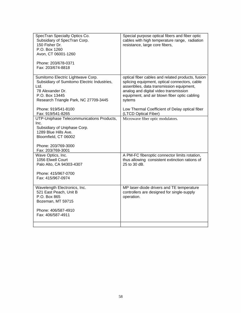
58
SpecTran Specialty Optics Co. Subsidiary of SpecTran Corp. 150 Fisher Dr. P.O. Box 1260 Avon, CT 06001-1260
Phone: 203/678-0371 Fax: 203/674-8818
Special purpose optical fibers and fiber opticcables with high temperature range, radiationresistance, large core fibers,
Sumitomo Electric Lightwave Corp. Subsidiary of Sumitomo Electric Industries,Ltd. 78 Alexander Dr. P.O. Box 13445 Research Triangle Park, NC 27709-3445
Phone: 919/541-8100 Fax: 919/541-8265
optical fiber cables and related products, fusionsplicing equipment, optical connectors, cableassenblies, data transmission equipment,analog and digital video transmissionequipment, and air blown fiber optic cablingsytems
Low Thermal Coefficient of Delay optical fiber(LTCD Optical Fiber)
UTP-Uniphase Telecommunications Products,Inc. Subsidiary of Uniphase Corp. 1289 Blue Hills Ave. Bloomfield, CT 06002
Phone: 203/769-3000 Fax: 203/769-3001
Microwave fiber optic modulators.
Wave Optics, Inc. 1056 Elwell Court Palo Alto, CA 94303-4307
Phone: 415/967-0700 Fax: 415/967-0974
A PM-FC fiberoptic connector limits rotation,thus allowing consistent extinction rations of25 to 30 dB.
Wavelength Electronics, Inc. 521 East Peach, Unit B P.O. Box 865 Bozeman, MT 59715
Phone: 406/587-4910 Fax: 406/587-4911
MP laser-diode drivers and TE temperaturecontrollers are designed for single-supplyoperation.
59
12.0 References
The following documents can be read from the 1996 Photonics CD-ROM published by LaurinPublications Co., Inc., Berkshire Common, Pittsfield, MA 01202 Phone: (413)499-0514. This is a greatsource for the photonic industry. Every engineer should have a copy.
Thermoelectric Coolers: Selecting the Right Cooling Systems for Laser Diodes and DetectorsJanet McDaniel,Marlow Industries, Inc.
Gradient Index Optics: An Old Technology, Gradient Index Lenses, Finds New ApplicationsLeland G. Atkinson and Douglas S. Kindred, Gradient Lens Corp.
Binary Optics: A Valuable Part of the Designer's Tool KitAlan Kathman and Eric Johnson, Teledyne Brown Engineering
Excimer, UV and VUV Laser Optics: Criteria to Consider When Choosing Components for an ExcimerSystem
Glen P. Callahan and Michael A. Case, Acton Research Corp.
Diffractive Optics: Taking the Approximation Out of Diffractive Optics DesignW. Kröninger and H.-G. Heckmann, Optische Werke G. Rodenstock, Precision Optics Div.
Adaptive Optics: Wavefront Sensing Branches OutLawrence E. Schmutz, Adaptive Optics Associates, Inc.
Bandpass Filter Design: Using Less Expensive Technology Without Sacrificing PerformancePaul D. Stupik, Ph.D., OCA/Optical Corporation of America
Beamsplitters: What a Designer Should Look for When Choosing a BeamsplitterMelles Griot, Catalog Div.
Polarization: Making Polarization Work in Your ApplicationGreg Kopp and Laura A. Pagano, Meadowlark Optics, Inc.
Mirrors: Reflecting on Materials for Substrates and CoatingsMelles Griot, Optics Div.
Mirrors: Applications in Imaging, Astronomy, Microscopes and Telephoto SystemsOptical Coating Laboratory, Inc. (OCLI)
Diffraction Gratings: Selection of Size and Type for Different Applications
60
Richardson Grating Laboratory, Spectronic Instruments, Inc.
Optical Components: Optical Objective Systems: A Schematic GuideWarren J. Smith, Kaiser Electro-Optics Inc.
Prisms Frequently Used in Optical SystemsBruce H. Walker, Walker Associates
Primary Lens Aberrations: Seven Ways a Lens Can Blur the Light It's Supposed to Focus-- Bruce H. Walker, Walker Associates
Simple Lens ApproximationsBruce H. Walker, Walker Associates
Common Lens Formulae-- Walker Associates
Filter Glass TransmissionSchott Glass Technologies Inc.
Filters: Neutral DensityG.J. Neville, Newark Scientific Inc.
Acousto-Optic Scanning Devices: CharacteristicsIsomet Corp. and Brimrose Corp. of America
Limiting Resolution NomogramJuan Rayces Consulting, Inc.
Fiber Amplifiers: Co-Doped Erbium: Ytterbium Fiber Amplifiers Enable New Applications-- Dennis L. Werth, ATx Telecom Systems, Inc.
Connectors: New Geometries and Materials Create New Generation of Connectors-- Gregory J. Sellers and S. Sriram, FORSS, Inc.
Fiber Optic Cable Selection: Factors to Consider When Choosing Fiber Optic Cables for Your System-- Giovanni P. Tomasi, BICC Brand-Rex Co.
Fiber Reliability: Large Flaws: The Culprit in Fiber Reliability-- Suresh T. Gulati, Corning Incorporated
Fibers/Medical Lasers: Three Silica-Core Fibers Rise to Top in Medical Laser Uses-- Brian P. McCann, 3M Specialty Optical Fibers
ATM: Asynchronous Transfer Mode -- Bandwidth for the Future-- Jim Lane, Telco Systems , Inc.
61
Sensors: A Comparative Evaluation of the Types and Applications of Various Sensors-- Vikram Bhatia, Kent A. Murphy, Marten J. de Vries and Millika B. Sen, Virginia Polytechnic Instituteand State University, Fiber and Electro-Optics Research Center
Sensors: Two Ways of Sensing with Fibers for Two Kinds of Applications-- David A. Krohn, 3M Specialty Optical Fibers
Fiber Optic Testing: Assessing Fiber Optics Systems and Their Major Components-- James E. Hayes, Fotec, Inc.
Transmission Conversion: dB to %Siecor Corp.
Coating Materials Technology: Selecting Materials and Deposition Techniques for Optical Coating-- CERAC, inc. (Technical assistance by Pellicori Optical Consulting )
Metals for Optical Applications
Optical Thin-Film Materials
Thin Films: The Advantages and Drawbacks of Physical Vapor Deposition Technologies-- Rolf Hora, Balzers Ltd.
Optical Design Software: Computer Software for Optical Coatings-- Philip Baumeister, Sholem Consultants
Coatings for First-Surface Mirrors-- Ferson Optics, Inc.
Ion-Beam Sputtering: Bringing Precise Control to Coatings Using Ion-Beam Sputtering-- Arthur T. Howe, Amoco Technology Co.; and Dennis D. Phillips, Optical Spectrum Technology
Antireflection Coatings for the Ultraviolet, Visible and Near-IR-- Balzers
BBAR* or MgF2 Coatings on Various Glasses: ReflectivityTropel
Focal Plane Arrays: Better, Smaller IR Imagers for New Applications-- J.T. Wimmers and D.S. Smith, Cincinnati Electronics Corp.
Infrared Detection Equipment: Parameters Used in Design-- Santa Barbara Research Center
Infrared Detectors: Expanded Applications Prompt Developments in Technology-- Konrad J. Stahl, AEG Aktiengesellschaft, Opto- and Vacuumelectronics Div.
Sensor Technology: Recent Advances in the 3- to 5-mm Band Overcoming Some Old Drawbacks-- Amber
Infrared Filters: Glossary, Equations, Parameters
62
-- Optical Coating Laboratory, Inc. (OCLI)
IR Fibers: New Designs, Methods Provide New Applications for IR FibersChristopher C. Gregory, Galileo Electro-Optics Corp.
Excimer Lasers: Once a Scientific Tool the Excimer Now Fills Many Roles-- Rainer Pätzel and Heinrich Endert, Lambda Physik GmbH, Göttingen, Germany
Ion Lasers: The Ion Laser, a Truly Enabling Technology-- Jeff Cannon and Stephen Lee, Coherent Inc., Laser Group
Gas Lasers: Reports of Gas Lasers' Demise Have Been Greatly Exaggerated-- KateLeggett
Tunable Diode Lasers: Cavity Design Considerations for Tunable Diode Lasers-- Dr. Timothy Day, New Focus, Inc.
Diode Lasers: Better Diode Lasers Will Expand Applications in Many Key Areas-- Bernard Masterson and Jeffrey Webb, Melles Griot, Electro-Optics Div.
Visible Laser Diodes: The Expanding Role of VLDs into the Burgeoning Commercial World-- David Martin, Toshiba America Electronic Components, Inc.
VCSELs: VCSELs Are Revolutionizing Optical Communications-- Greg R. Olbright, Vixel Corp.
Semiconductor Laser Diodes: Fundamental Issues in Their Use for a Growing Number of Applications-- David L. Begley, Ball Corp., Aerospace Systems Div.
Optical Parametric Oscillators: The Modern OPO Takes Its Place as a Reliable Research Tool-- Michael B. Radunsky, Ph.D., Continuum
Medical Lasers: Taking the Confusion Out of Matching Medical Lasers-- J. Michael Yarborough, Coherent Inc., Tucson Research Center
Industrial Lasers: Making the Right Decision in Choosing an Industrial Laser-- Thomas R. Kugler and Gary Hermann, Lumonics Corp., Industrial Products Div.
Ti:Sapphire Tuning: Tuning the Continuous-Wave Ti:Sapphire Laser-- Peter F. Moulton, Schwartz Electro-Optics, Inc.,
Beam Steering: Laser Marking Steers a New Course in Manufacturing-- Richard L. Stevenson, Excel/Control Laser, Inc.
Laser Beam Diagnostics: Boosting Efficiency with Feedback on Beam Diagnostics-- Roger Rypma, Coherent, Inc., Instruments Div.
Safe Handling of Excimer Laser Gases: Precautions That Prevent Accidents in the Use of CompressedLaser Gases-- Al Dietz and Elaine Bradford, Spectra Gases, Inc.
Laser-Induced Damage Testing: Using High-Energy Exposure to Gage Optical Components
63
-- Steven C. Seitel, Big Sky Laser Technologies, Inc.
Materials Processing Laser Capabilities-- Convergent Energy
Properties of Nd3+ Laser Host MaterialsBall Corp., Aerospace and Communications
Tungsten Halogen: An Economical, Reliable Choice for Illuminating Vision Applications-- Michael Muehlemann, Illumination Technologies, Inc.
Solar Spectral Irradiance-- Oriel Instruments
Short Arc Lamps: Fundamental Characteristics of High-Intensity Point Sources-- ORC Lighting Products, Div. of Benson Eyecare Corporation
High-Power Light Sources: Design, Material, Power Conditioning Are Key in Choosing a Source-- Gary G. Albach, Vortek Industries Ltd.
Standard CIE Illuminants-- Walker Associates
High-Brightness Materials: Advances in LED Performance Open New Markets for the TechnologyFrank M. Steranka and Mark Hodapp, Hewlett- Packard Co.
Global Optimization: A Powerful Lens Design Tool for the Optical Engineer-- Thomas G. Kuper and Thomas I. Harris, Optical Research Associates
Optical Design Software: Hard- and Software Considerations for Designing with a Computer-- Douglas C. Sinclair, Sinclair Optics, Inc.
Optical Component Specifications: Avoiding Pitfalls in Setting Tolerances for Optical Components-- Warren J. Smith, Kaiser Electro-Optics Inc.
Cost of Manufacturing vs. Tolerances-- Plummer Precision Optics and Walker Associates
Gaussian and Newtonian Thin Lens Formulae-- Walker Associates
Surface Tolerances: Ensuring an Optical Element's Compatibility with Its System-- Bruce H. Walker, Walker Associates
Designing Plastic Optics: New Applications Emerging for Optical Glass Substitutes-- Claude Tribastone, Chuck Teyssier and William Peck, OPKOR Inc.
Laser Scanning System Design: Choosing Elements to Fit the Nature of an Application-- Glenn E. Stutz, Lincoln Laser Co.
Single-Point Diamond Machining:Diamond Machining: Cost-Effective Route to Precision Optics
64
-- Rank Pneumo, Inc.
Optical Machining: Controlling the Variables with a Well-Designed ToolBob Roberts, R. Howard Strasbaugh, Inc.
Beryllium Mirrors: Production Techniques Drop Costs without Altering High Reflectivity-- Thomas B. Parsonage, Brush Wellman, Inc., Beryllium/Mining Div.; and Peter N. Richard, HardricLaboratories, Inc.
Optical Materials: Properties and Applications-- William L. Truett, Janos Technology, Inc.
Transmission Ranges for Some Materials-- Janos Technology, Inc.
Optical Materials: Transmission and Refractive Index-- Janos Technology, Inc.
Optical Glasses-- Bruce H. Walker, Walker Associates
Maps of Optical Glasses-- Walker Associates
Coefficients of Expansion and Densities of Optical Materials-- Walker Associates
Fused Silica: Optical Properties-- Dynasil Corporation
Refractive Indices of Glasses at Laser WavelengthsSchott Glass Technologies Inc.

65


![Novel Design for Photonic Crystal Ring Resonators Based ...jopn.miau.ac.ir/article_3046_01eb01affabdaa909e9328069782f311.pdf · employing photonic crystals [4]. In recent years, photonic](https://img.pdfslide.us/doc/110x75/5e7ed386707cf3599e6c8522/novel-design-for-photonic-crystal-ring-resonators-based-jopnmiauacirarticle304601eb01affabd.jpg)