Embed Size (px)
Citation preview

Phosphogypsum disposal in Greece
V. Koukouliou
EMRAS 2006
Greek Atomic Energy Commission

•The fertilizer industry is in operation since 1965
•Location: north Greece, by the sea
•According to Greek legislation for waste disposal, each industry has to submit to the local authorities an environmental study that has to include:
detailed description of the geological and hydrological situation at the disposal site
proposed measures to prevent pollution
• GAEC has to give an expert opinion on the radioactivity issues
Existing situation

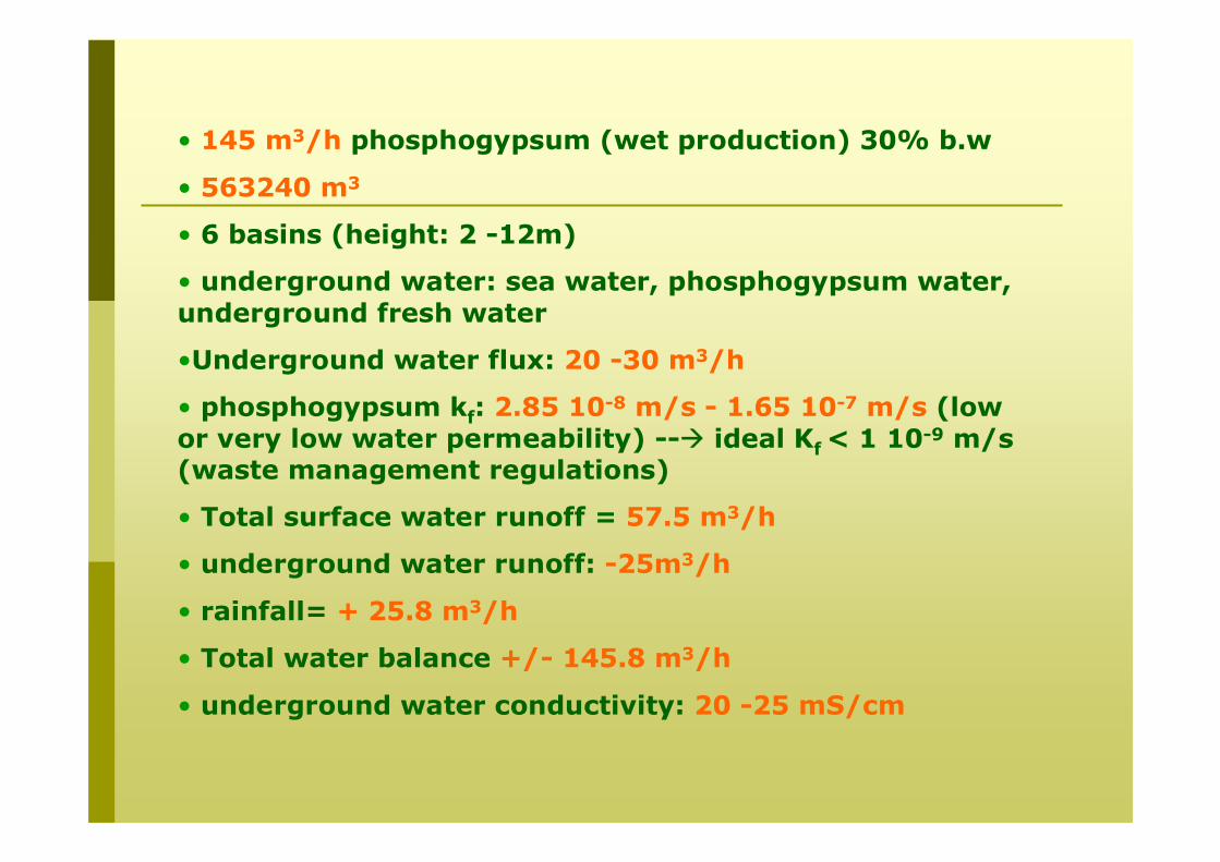
• 145 m3/h phosphogypsum (wet production) 30% b.w
• 563240 m3
• 6 basins (height: 2 -12m)
• underground water: sea water, phosphogypsum water, underground fresh water
•Underground water flux: 20 -30 m3/h
• phosphogypsum kf: 2.85 10-8 m/s - 1.65 10-7 m/s (low or very low water permeability) -- ideal Kf < 1 10-9 m/s (waste management regulations)
• Total surface water runoff = 57.5 m3/h
• underground water runoff: -25m3/h
• rainfall= + 25.8 m3/h
• Total water balance +/- 145.8 m3/h
• underground water conductivity: 20 -25 mS/cm

lake
sea
Draining channel
Phosphogypsum dyke
Clay dykePump for surface water
Existing situation
(563.240m2)
Inactive site

Environmental data

5
1
2-3
4
6
North: clay layer at 3.5m from east – 5.5-6.0 m center, water: 0.8-2.4m underground runoff of the pg drainage to N
West: clay layer at 2, water: 0.8-2m (sub pressure)- no underground runoff
sand, gravel phosphogypsum sand, gravel, pg clay c, s, g clay, mud c,s
1.2
2
3.5
6
0.5
2.5
3.5
6
7
Kf=8 10-5 m/s
Kf=9 10-8 m/s
East: clay layer at 4.5m NE, water: 2.1-2.9m, lack of clay layer underground runoff of the pg drainage to S
South: sand up to 7m, water: 2-5 m underground runoff of the pg drainage the sea
1
3
4
4.8
0.2
2.2
5.2
6.5
N
N
E
W

Distribution of piezoelectric level of the underground water
Flow direction

pH distribution for the unsaturated soil layer
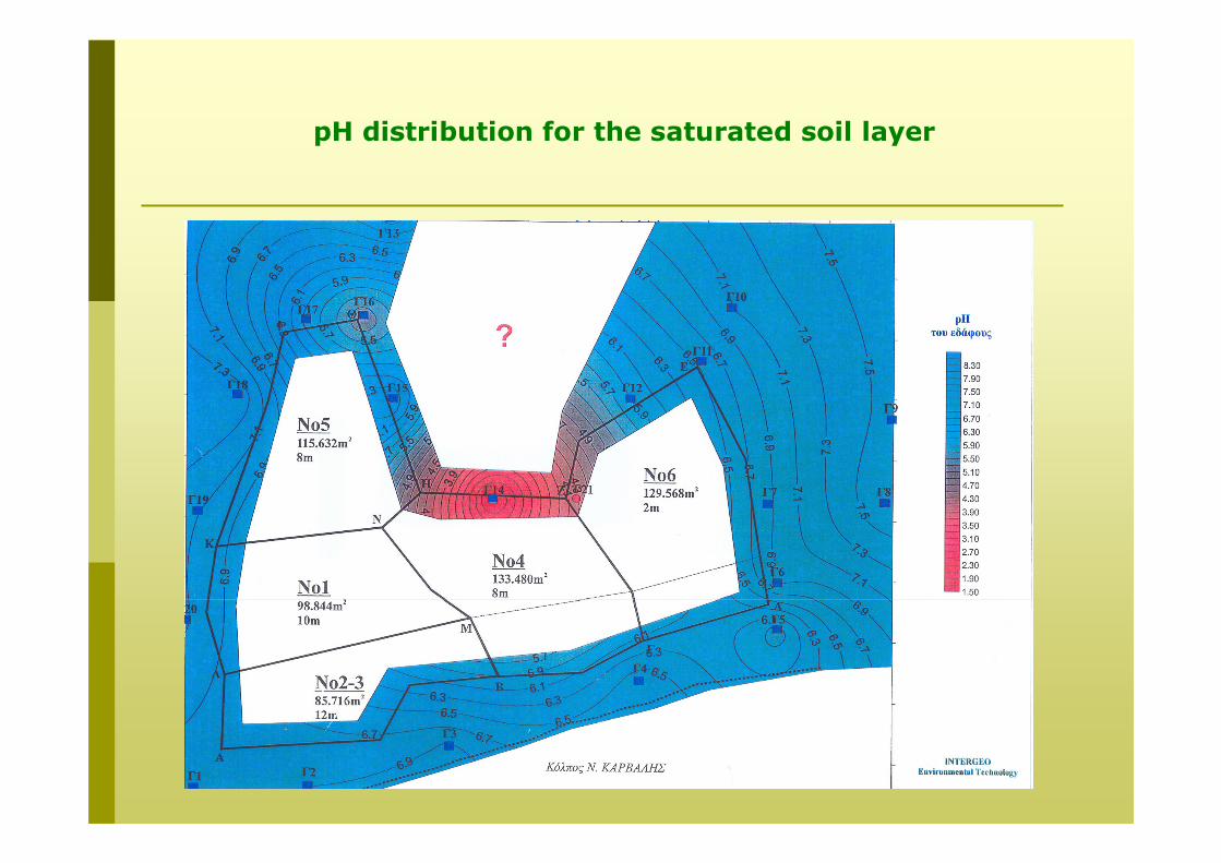
pH distribution for the saturated soil layer

Underground water: pH distribution
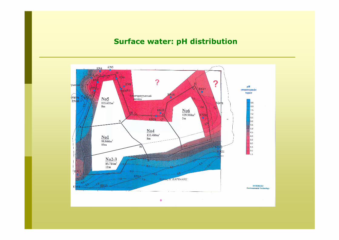
Surface water: pH distribution

Water balance
Phosphogypsum water
Rainfall Evaporation
phosphogypaum
Surface runoff
Underground water outflowUnderground water
inflow
Water loss due to suspension
freeze

Conclusions
• The underground water pH is significantly low (min= 1.93), specially at the north.
• The low pH values are correlated with increased SO4 & P2O5concentrations.
• The underground water pollution is mainly due to underground phosphogypsum drainage water runoffs (10-20 m3/h), mainly at north, east and south:
• lower to the east
• the clay layer presents a significant incline to E-NE
• at the N, E & S site existence of water permeable layers at the underground water level.

• Construction of new perimetric drainage channels with maximum depth of 2m. The water will be collected and guided with a special pump at the existing draining channel and then back to the phosphoric production unit.
• The proposed system satisfactory solves the surface water drainage problem, but it does not take into account the underground waterrunoff (<2m)
• The underground clay layer is not consistent. Moreover, it has a grade and it some areas it disappears, so the vertical discharge is favored
• At the south site (sea), phospogypsum is no longer disposed, but measures must be taken in order to avoid sea pollution due to underground water runoff (according to the geological characterization, there is a water permeable sand layer at the south).
• At the west site, the existing channel, the very low permeable layer (clay), the non- existence of a leakage point (based on piezoelectric measurements) and the direction (west to east) of the underground water flow, prevent the surface and underground runoff.
Proposed measures

• The main problem is the underground runoffs specially at the north and east site.
Proposed solutions:
moderatemoderateModerate-low
moderateMinimum3
LowModerateVery bigModerateBig2
ModerateMinorBigModerateVery big1
Operation cost
MaintenanceInstallationCost
EfficiencyDifficultiesOption
1. Construction of a deep channel down to clay layer
2. injection of special insulating material
3. Hydraulic retention of underground drainage

lake
sea
Draining channel
Phosphogypsumdyke
Clay dykePump for surface water
Proposed draining channel
Proposed well
Proposed measures
Inactive site
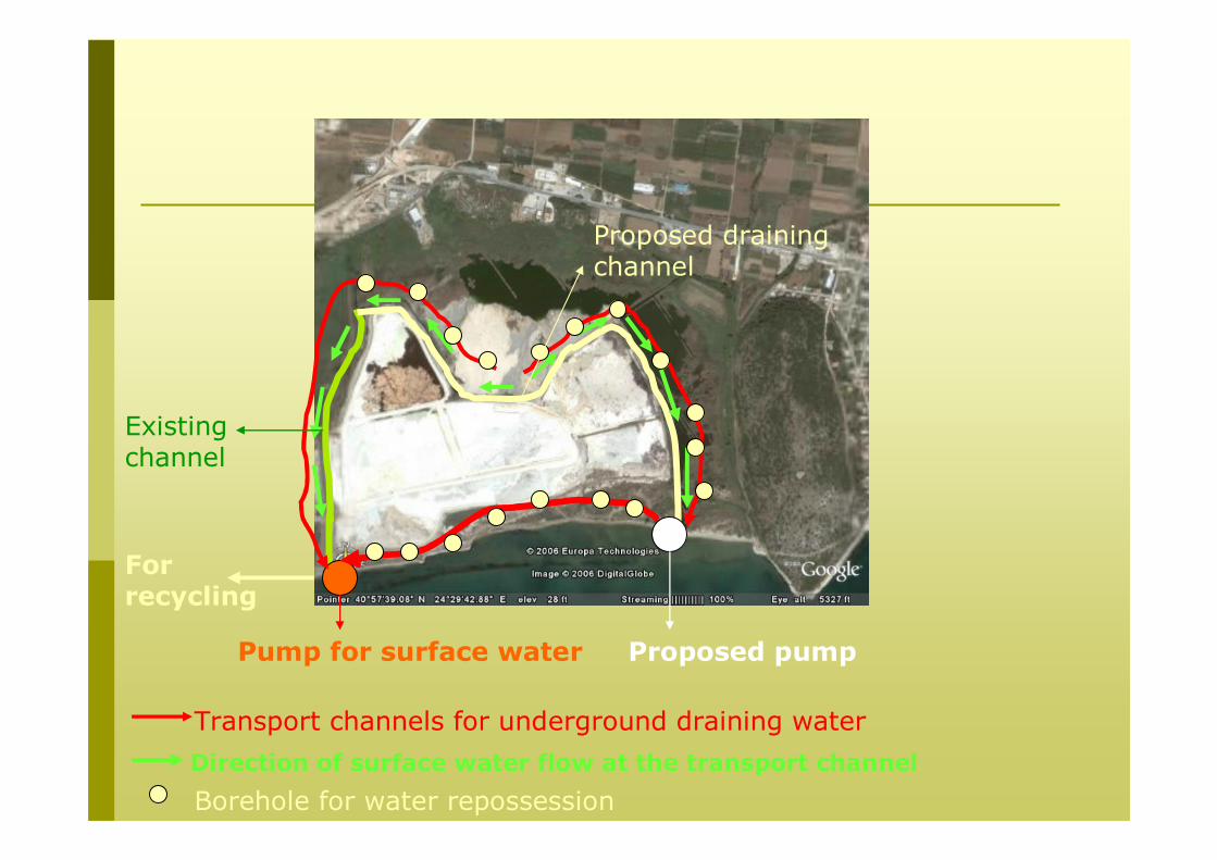
Pump for surface water Proposed pump
Direction of surface water flow at the transport channel
Transport channels for underground draining water
For recycling
Borehole for water repossession
Proposed draining channel
Existing channel

phopshogypsum
Underground water
Clay layer
Concentrated pg Soil
Borehole for water repossession
Pg dyke, H: 2m W: 5m
Peripheral drainage dyke
Proposed system

QUESTION to GAEC:
Are the proposed measures suitable also for the radionuclides?

Measurements performed:
• phosphogypsum (gamma spectroscopy)
• underground and surface water (U-238 & Ra-226 with a-spectroscopy)
• leaching experiments

sd
Mean
Min – max
Bq/kg
2821311218134
1551432138381
4 – 7303 –58111 – 48512 –84118 –598
K-40Th-228Pb-210U-238Ra-226
Phosphogypsum samples

U-238, Ra-226 Surface water
250 mBq/l1057 mBq/l
147mBq/l55mBq/l
29mBq/l
430mBq/l
2183mBq/l136mBq/l
1037mBq/l70 mBq/l 22 mBq/l
176 mBq/l
250 mBq/l15mBq/l
26 mBq/l15 mBq/l
67 mBq/l18 mBq/l
1352 mBq/l18 mBq/l

Underground water U-238, Ra-226
870 mBq/l
Typical values:
U: 3 – 65mBq/l
Ra: 4 – 1500mBq/l(spas)
5000 mBq/l5000 mBq/l
7000 mBq/l600 mBq/l
910 mBq/l5400 mBq/l
297 mBq/l115 mBq/l
400 mBq/l19 mBq/l
121 mBq/l97 mBq/l
250 mBq/l6 mBq/l
245 mBq/l516 mBq/l
280 mBq/l1203 mBq/l

7000 mBq/l U-238
600 mBq/l Ra-226
N
sand, gravel phosphogypsum sand, gravel, pg clay c, s, g clay, mud c,s
5000 mBq/l U-238
5000 mBq/l Ra-226