Embed Size (px)
Citation preview

PHILIPP Power Box System
Installation Instruction
VB
3-V-
002-
en -
01/1
6

PHILIPP Power Box System
2 © 2016 PHILIPP GmbH, 63741 Aschaffenburg • Technical changes and errors reserved • January 2016
Transport and mounting systems for prefabricated building
Technical department Our staff will be pleased to support your planning phase with suggestions for the
installation and use of our transport and mounting systems for precast concrete construction.
Special designs Customized to your particular needs.
Practical tests on site We ensure that our concepts are tailored precisely to your requirements.
Inspection reports For documentation purposes and your safety.
On-site service Our engineers will be pleased to instruct your technicians and production per-
sonnel at your plant, to advise on the installation of precast concrete parts and to assist you in the optimisation of your production processes.
High safety level when using our products Closecooperationwithfederalmaterialstestinginstitutes(MTIs),andofficialap-
provals for the use of our products and solutions whenever necessary.
Software solutions The latest design software, animated videos and CAD libraries can always be
found under www.philipp-gruppe.de.
Engineering contact Phone: +49 (0) 6021 / 40 27-318
Fax: +49 (0) 6021 / 40 27-340 E-mail: [email protected]
Sales contact Phone: +49 (0) 6021 / 40 27-300
Fax: +49 (0) 6021 / 40 27-340 E-mail: [email protected]

3© 2016 PHILIPP GmbH, 63741 Aschaffenburg • Technical changes and errors reserved • January 2016
System components .............................................................. Page 4
Application ............................................................................. Page 5
Design and construction ........................................................ Page 6
Reinforcement ....................................................................... Page 7
Design example .................................................................... Page 8
Installation ............................................................................. Page 9
Preparation ............................................................................ Page 9
Mounting ............................................................................... Page 10
PHILIPP Grouting mortar ....................................................... Page 11
Software / CAD ..................................................................... Page 13
General notes ........................................................................ Page 14
Content
VRd,II
VRd,┴
VRd,II
VRd,┴

PHILIPP Power Box System
4 © 2016 PHILIPP GmbH, 63741 Aschaffenburg • Technical changes and errors reserved • January 2016
The Power Box System is optimally harmonised and consists of: ThegalvanisedPowerBoxincludingahigh-capacity,flexiblesteelwireropeandaplasticcover High-strength,free-flowinggroutingmortar(Picture3)
System components and dimensionsThe Power Box System is used for the connection of precast concrete units where a transfer of high loads and a proof for it is required. It is able to transfer shear forces parallel and right-angled to the wall safely into the concrete unit (see page 3).Its simple installation by means of a timber board ensures a practice-oriented application.
Table 1: Dimensions of the Power BoxRef.-No. Dimensions
[mm]PU Weight
SL B H L L1 [pcs.] [kg/PU]54PB120 120 80 25 220 190 100 42.0
Picture 1
L
B
H
SL
L1
Advantages at a glance: Flexible connecting elements No complicated “rebend” required High bearing capacity Shear forces right-angled and parallel to the joint possible Simple design due to shear force data per Power Box Cost-optimized due to stackable transport packaging Optimal utilization because of variable number of Power Boxes per joint Box cover recyclable Stable box cover also suitable for hot bonding Weatherproof box cover Approved by DIBt (Deutsches Institut für Bautechnik, Germany, www.dibt.de)
Picture 2 Picture 3
L
System components

5© 2016 PHILIPP GmbH, 63741 Aschaffenburg • Technical changes and errors reserved • January 2016
Range of applications and examplesThe Power Box System can be used for almost all connec-tions of reinforced precast concrete wall elements. Primar-ily, it transfers static shear loads parallel or right-angled to the wall. Tensile forces in the joint (along the wall) have to be excluded or taken by appropriate static or constructive measures.
Geometry of precast unitsThe reinforced concrete elements must have a minimum thickness of 14 cm. If shear forces right-angled to the joint have to be transferred the wall thickness must be increased to 18 cm. In general, a maximum joint height of 3.5 m is allowed.
Higher joints are possible if the subsequent grout-ing of the joint is made step-by-step in sections of 3.5 m with a grouting hose.
Application
The Power Box System can be used if it is proofed for par-ticular applications that the control of the crack width in the jointisfulfilledaccordingtoEN1992,table18,orthecorro-sion protection is ensured by other measures.
Picture 6
Picture 7
Picture 5
Picture 4
30
90m
in. 3
0m
in. 3
0
min
.140
Stirrup Ø8/250,anchoring length acc. to EC 2
B500A Ø10
20 20
20
B500A Ø12≥50
B500A Ø12
B500A Ø12
Picture 8
20
B500A Ø12
80
25 40

PHILIPP Power Box System
6 © 2016 PHILIPP GmbH, 63741 Aschaffenburg • Technical changes and errors reserved • January 2016
The reinforced precast concrete units to be connected must correspond to EC 2. Furthermore, the precast units have to be made of normal weight concrete with a strength class of at least C30/37 according to EN 206. The structural engi-neer is responsible to design the elements and to prove the joint connection according to the German national technical approval (Z-21 8-1840).
Values for the design shear resistance parallel to the wall (VRd,II) as well as right-angled to the wall (VRd,┴) are as fol-lows:
Reduction factor = 1/3 + 0.025 × (40 – VEd,II)VRd,┴ = Reduction factor × Tabular value
Table 2: Design shear resistance parallel and right-angled to the joint (wall level)Wall thickness
h Design shear resistance
C30/37 C35/45 C40/50 C45/55VRd,II VRd,┴ VRd,II VRd,┴ VRd,II VRd,┴ VRd,II VRd,┴
[cm] [kN/Box] [kN/m] [kN/Box] [kN/m] [kN/Box] [kN/m] [kN/Box] [kN/m] 14
40.0
6.2
40.0
7.1
40.0
7.6
40.0
8.1 16 8.9 10.1 10.9 11.6
18 11.9 13.5 14.5 15.420 15.0 17.1 18.4 19.622 18.4 21.0 22.5 24.024 22.0 25.0 26.9 28.6
Design shear resistance VRd,┴ for wall thicknesses < 18 cm only possible if joint or element length > 100 cm.
The percentage of the shear force right angled to the joint is given in diagram 1 or calculated as follows:
With VEd,II ≤ 13 kN/Box it is possible to take VRd,┴ given in table 2 with 100 % for the design! With VEd,II > 13 kN/Box VRd,┴ must be multiplied with the following reduction factor:
Diagram 1: Interaction of shear forces right-angled and parallel to the joint
Design and construction
If there are shear forces right-angled to the joint, a tensile force must be considered, which is one and a half times of the transferred shear force. This tensile force can be transferred via appropriate reinforcement, e.g. arranged as aringbeam,orotherconstructivemeasures(e.g.fixedcol-umn, friction forces).If both shear forces occur an interaction is necessary, then the shear force right-angled to the joint (VRd,┴) can only be considered partly. For this VRd,┴ must be multiplied with a design factor. Diagram 1 shows the interaction between the shear forces parallel and right-angled to the joint.
Fire protectionIn addition to the actual approval the joint construction is alsocertifiedbytheUniversityofKaiserslautern,Germany,for the fire protection class F180 (with a minimum wall thickness of 15 cm) on the basis of EC 2 and EC 3.
AconstructionwiththePowerBoxdoesnottransferfirenorsmoke before the 180th minute. Also inadmissible tempera-ture increases above the initial temperature at the beginning do not occur so that the structural stability is guaranteed.
VR
d,II
[kN
/Pow
er B
ox]
VRd,┴ [% value from table 2]

7© 2016 PHILIPP GmbH, 63741 Aschaffenburg • Technical changes and errors reserved • January 2016
By means of a timber board the Power Box is installed. The minimum distance between the Power Boxes of 12 cm and to the edge of 15 cm must not be exceeded (Picture 9).In the range of the Power Boxes the precast elements must
This requirement is fulfillede.g.byamesh reinforcementType R257A (equivalent: 2.57 cm²/m).
The end anchorage of the connecting loops must be aligned right-angled to the Power Box in the precast element. For a vertical installation in the mould the alignment of the wire loops in the precast unit should be ensured by tying those to the reinforcement.
Alternatively, the stirrups can be replaced by a comparable mesh reinforcement (Picture 10).
be provided with a minimum reinforcement. This reinforce-ment shall be stirrups Ø8 for each wire loop and longitudinal reinforcement 2 × Ø10 (Picture 9, alternatively Picture 10).
Reinforcement
Picture 9 Picture 10
220
min. 150
220 max.3750
170
170
A bending of the end anchorage by the reinforce-ment is not allowed.
Picture 11
Longitudinal reinf. Ø10
Stirrup Ø8
Mesh capR257A
Longitudinal reinf. Ø10
170
min. 120
220
min. 120
min. 150
220
min. 150
220 max.3750
min. 120
220
min. 120
min. 150

PHILIPP Power Box System
8 © 2016 PHILIPP GmbH, 63741 Aschaffenburg • Technical changes and errors reserved • January 2016
Example wall supportIn this example the support reactions of a panel are transferred via the Power Box System. Not only the dead weight of the panel but also the weight of the beam and the ceiling boards as well as variable loads are taken into consideration.
Actions to the joint: Weight of the panel: 2.5 m × 4.0 m × 0.18 m × 25 kN/m3 = 45 kN Weight of ceiling boards and beam: 120 kN Significantvariableforce:30kN Buildingheight≤10m,windzone1,innerland,accordingtoEC1
Herewith the final design value is calculated (shear force parallel to the joint): VEd,II = (1.35 × (45 kN + 120 kN) + 1.5 × 30 kN) / 2 = 133.9 kN for each jointVEd,II = 133.9 kN / 2.5m = 53,6 kN/m for each joint
Shear force right-angled to the joint caused by wind:VEd,┴ = 1.5 × (0,8 kN/m2 × 0.5 × 2.5 m × 4.0 m) / 2 = 3 kN/m for each jointChosen concrete strength: C30/37Chosen number Power Box pairs: n = 4
As a result the resistance forces (right-angled and parallel) are: Shear force parallel: VRd,II = 40 kN × 4 boxes / 2.5 m = 64 kN/m (forces for each box: VEd,II / 4 = 133.9 kN / 4 = 33.5 kN/box)Shear force right-angled: VRd,┴ = 11.9 kN/m (value from table 2)If both forces occur at the same time an interaction (Diagram 1) must be considered:Reduction factor = 1/3 + 0.025 × (40 kN – 33.5 kN) = 0.50
The reduced shear force right-angled to the joint can be set to 50 % red. VRd,┴=0.50×11.9kN/m=5.95kN/m≥3.0kN/m=VEd,┴
This calculation shows that not only the dead weight of the panel but also high forces of beam constructions and wind loads at the same time can be transferred by the Power Box system.
Design example
Picture 12
Picture 12a
Picture 12b
VRd,┴
vRd,II
VRd,┴
vRd,II
2.5 m
4.0 m0.18 m
9© 2016 PHILIPP GmbH, 63741 Aschaffenburg • Technical changes and errors reserved • January 2016
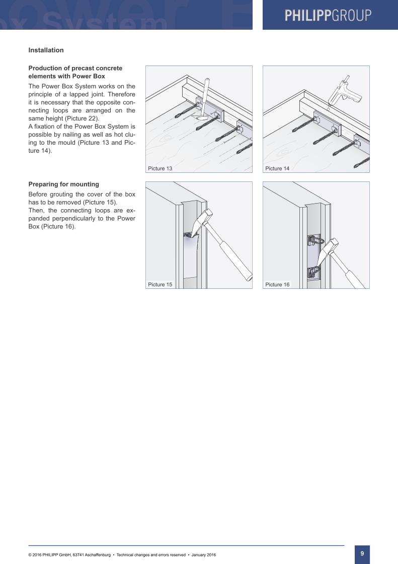
Production of precast concrete elements with Power BoxThe Power Box System works on the principle of a lapped joint. Therefore it is necessary that the opposite con-necting loops are arranged on the same height (Picture 22). AfixationofthePowerBoxSystemispossible by nailing as well as hot clu-ing to the mould (Picture 13 and Pic-ture 14).
Installation
Preparing for mountingBefore grouting the cover of the box has to be removed (Picture 15). Then, the connecting loops are ex-panded perpendicularly to the Power Box (Picture 16).
Picture 13 Picture 14
Picture 15 Picture 16

PHILIPP Power Box System
10 © 2016 PHILIPP GmbH, 63741 Aschaffenburg • Technical changes and errors reserved • January 2016
Mounting and groutingIf the Power Boxes are installed cor-rectly the loops overlap horizontally with nominal 90 mm as shown in pic-ture 17. Ideally, in vertical direction there is no distance between the loops from both sides (Picture 19).Nevertheless, the approval for the Power Box System already considers horizontal and vertical tolerances. The maximum tolerances for all cases are shown in picture 20 to 22.Prior sealing the joint a reinforcement bar (Ø12 mm) shall be positioned along the entire length of the joint through the overlapping loops. Make sure when using an expanding wa-terstop tape that it does not affect the grouting cross section or reduces the required concrete cover for the Power Box System. The appropriate installation should be inspected visually. After this the joint issealedonbothsidesandfilledwithgrouting mortar. The use of a grouting hose with a filling hopper eases thisprocesssignificantly.Itisrecommend-ed tofill the joint insections inorderto reduce the pressure of the grouting mortar.The grouting mortar should be mixed, filled in and compacted according tothe processing instructions given on page 11.
Mounting
20
B500A Ø12 90
B500A Ø12
10
100B500A Ø12
40
70B500A Ø12
B500A Ø12
max. 20
Picture 17 Picture 18
≥50
Picture 21 Picture 22
Picture 19 Picture 20

11© 2016 PHILIPP GmbH, 63741 Aschaffenburg • Technical changes and errors reserved • January 2016
PHILIPP Grouting mortar
Grouting with PHILIPP Grouting mortarThe grouting mortar is a joint mortar for the approved Power Box System. It is a ready-to-use dry mixture on a cement base for grouting of precast concrete units. Furthermore, it is shrinkage-free,hasahighearlyandfinal strengthandgoodflowability.
Pre-treatmentThe surface must be clean of oils, greases etc. and cement slurry at the surface shall be removed. Each time a seal formwork should be used. In order to improve the adhesion the joint surface shall be pre-wetted thoroughly.
PropertiesThe grouting mortar is free of chlorides. It has a good adhe-sion to steel and concrete and shows no signs of separation of the components. Furthermore it has a good pumpability and resistance to frost deicing salt. The grouting mortar is produced in consistently high quality and is easy to pro-cess.Duetoitsflowableconsistencythemortarisself-lev-ellingandfillsoutallaccessibleventinghollowspaces.
Mixing and groutingApproximately 2/3 of the mixing water is put into the mixer first,thenthegroutingmortarisstirredincompletely.After-wards the remaining water is used to adjust the consistency. Mixing time is 4-6 minutes, depending on the type of mixing. Finally, the joint is sealed at both sides (if this has not been donebefore)beforeitisfilledwithgroutingmortar.Theuseofagroutinghosewithafillinghoppereasestheprocesssignificantly.Itisrecommendedtofillthejointinsectionsinorder to reduce the pressure of the grouting mortar. Make sure when using an expanding waterstop tape that it does not affect the grouting cross section or reduces the required concrete cover for the Power Box System.
Processing temperatureDIN 1045-2 and DIN EN 206-1 must be taken into consider-ation when working with the grouting mortar. These stand-ards set a processing temperature to a minimum of +5°C.
Post-treatmentIt should be prevented that the mortar dries up to fast for at least three days after the grouting. Appropriate measures are covering with plastic sheets, application of wet tissues or watering.
During grouting, make sure that the air can dis-appear. A careful vibrating can avoid trapped air. The processing time is approximately 60 minutes at 20°C.
Picture 25
Picture 23
3.0 litres
4-6 minutes
Picture 24

PHILIPP Power Box System
12 © 2016 PHILIPP GmbH, 63741 Aschaffenburg • Technical changes and errors reserved • January 2016
Software / CAD
Calculation toolIn order to design connections with the PHILIPP Power Box System you can find a calculation tool on our website (www.philipp-group.de) - a free software without any registration.
Part libraryTime saving during the planning process and support for modelling complicate solutions is getting more and more important andthePHILIPPCADlibraryhelpstoworkefficientonthatmatter.
More than 1,200 PHILIPP products are available as 3D model.
Universal CAD library with many export formats suitable for all CAD systems (e.g. IFC, DWG)
Free offer for all people involved in precast building
Time saving in the design process because of ready-made models and views
Simply structured catalogue Further product details are provid-
ed (e.g. weight, dimensions, mate-rial and instructions)
13© 2016 PHILIPP GmbH, 63741 Aschaffenburg • Technical changes and errors reserved • January 2016
General notes
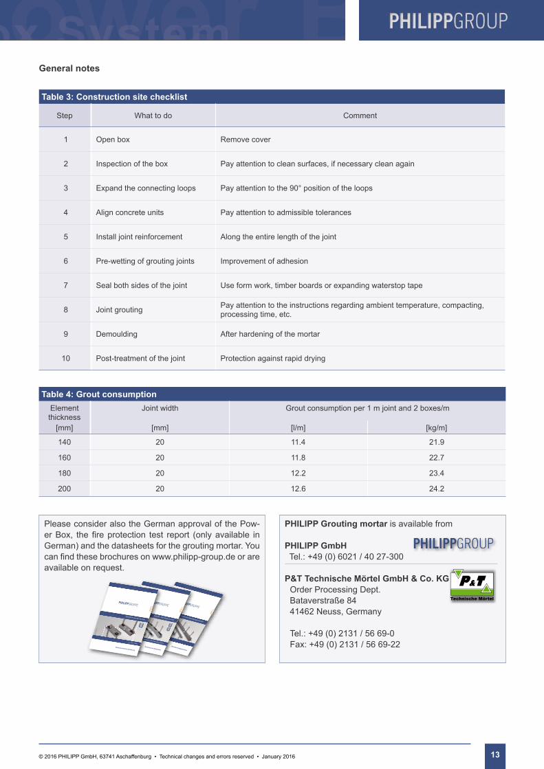
Table 4: Grout consumptionElement thickness
Joint width Grout consumption per 1 m joint and 2 boxes/m
[mm] [mm] [l/m] [kg/m]
140 20 11.4 21.9
160 20 11.8 22.7
180 20 12.2 23.4
200 20 12.6 24.2
Table 3: Construction site checklist
Step What to do Comment
1 Open box Remove cover
2 Inspection of the box Pay attention to clean surfaces, if necessary clean again
3 Expand the connecting loops Pay attention to the 90° position of the loops
4 Align concrete units Pay attention to admissible tolerances
5 Install joint reinforcement Along the entire length of the joint
6 Pre-wetting of grouting joints Improvement of adhesion
7 Seal both sides of the joint Use form work, timber boards or expanding waterstop tape
8 Joint grouting Pay attention to the instructions regarding ambient temperature, compacting, processing time, etc.
9 Demoulding After hardening of the mortar
10 Post-treatment of the joint Protection against rapid drying
Please consider also the German approval of the Pow-erBox, thefireprotection test report (onlyavailable inGerman) and the datasheets for the grouting mortar. You canfindthesebrochuresonwww.philipp-group.deorareavailable on request.
PHILIPP Grouting mortar is available from
PHILIPP GmbHTel.: +49 (0) 6021 / 40 27-300
P&T Technische Mörtel GmbH & Co. KG Order Processing Dept. Bataverstraße 84 41462 Neuss, Germany
Tel.: +49 (0) 2131 / 56 69-0 Fax: +49 (0) 2131 / 56 69-22
PHILIPP Verbindungsschienen und Verbindungsschlaufen
Brandschutzgutachten
VB3-
VG-0
01-d
e - 1
0/12
VB3-
V-00
8-de
- 06
/14
- 1/1
500
PHILIPP - P&T Vergussmörtel
Technisches Datenblatt
für das Power Duo- und Power Box System
PHILIPP Power Box System
Bauaufsichtliche Zulassung
Z - 21.8 - 1840
VB3-
VZ-0
02-d
e-D
E - 0
5/17

PHILIPP Power Box System
14 © 2016 PHILIPP GmbH, 63741 Aschaffenburg • Technical changes and errors reserved • January 2016
Notes:

15© 2016 PHILIPP GmbH, 63741 Aschaffenburg • Technical changes and errors reserved • January 2016
Notes:

For more information visit our website: www.philipp-group.de
Sustainablesolutions
Our customers trust us to deliver. We do everything in our power to reward their faith and we start each day intending to do better than the last. We provide strength and stability in an ever-changing world.
Welcome to the PHILIPP Group
PHILIPP GmbHLilienthalstrasse 7-9D-63741 AschaffenburgPhone: +49 (0) 6021/40 27-0Fax: +49 (0) 6021/40 [email protected]
PHILIPP GmbHRoßlauer Strasse 70D-06869 Coswig/AnhaltPhone: +49 (0) 34903/6 94-0Fax: +49 (0) 34903/6 [email protected]
PHILIPP GmbHSperberweg 37D-41468 NeussPhone: +49 (0) 2131/59 18-0Fax: +49 (0) 2131/59 [email protected]
PHILIPP Vertriebs GmbHLeogangerstraße 21A-5760 Saalfelden / SalzburgPhone + 43 (0) 6582 / 7 04 01Fax + 43 (0) 6582 / 7 04 01 [email protected]
01/1
6