Embed Size (px)
Citation preview
Rev by: BMA 6/23/2017
PHILADELPHIA GAS WORKS
SPECIFICATION FOR INSTALLING
PRIVATELY OWNED
UNDERGROUND NATURAL GAS HOUSE PIPING
FOR
HOUSING PROJECTS, CONDOMINIUMS, APARTMENTS, INDUSTRIAL SITES OR SIMILAR
COMPLEXES
June, 2017
PGW UNDERGROUND HOUSE PIPING MANUAL
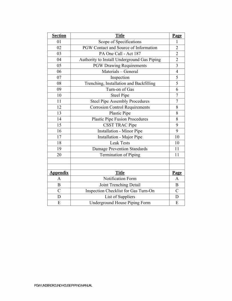
Section Title Page
01 Scope of Specifications 1 02 PGW Contact and Source of Information 2 03 PA One Call - Act 187 2 04 Authority to Install Underground Gas Piping 2 05 PGW Drawing Requirements 3 06 Materials – General 4 07 Inspection 5 08 Trenching, Installation and Backfilling 5 09 Turn-on of Gas 6 10 Steel Pipe 7 11 Steel Pipe Assembly Procedures 7 12 Corrosion Control Requirements 8 13 Plastic Pipe 8 14 Plastic Pipe Fusion Procedures 8 15 CSST TRAC Pipe 9 16 Installation - Minor Pipe 9 17 Installation - Major Pipe 10 18 Leak Tests 10 19 Damage Prevention Standards 11 20 Termination of Piping 11
Appendix Title Page A Notification Form A B Joint Trenching Detail B C Inspection Checklist for Gas Turn-On C D List of Suppliers D E Underground House Piping Form E
P a g e | 1
PGW UNDERGROUND HOUSE PIPING MANUAL
Specifications for Installing Private Underground Gas Piping for
Housing Projects, Condominiums, Apartments, or Similar Complexes NOTE: These specifications are subject to change without notice. Consult with the
Operations Department of the Philadelphia Gas Works (PGW) before starting any installation. All references to statutes, rules or regulations are current as of the date of publication, but remain the responsibility of the Owner/Contractor, with respect to modification or other changes in laws or regulations. PGW makes no warranties or certification expressed or implied with respect to the methods or procedures contained herein.
Section 01. Scope of Specifications
1. Federal Regulations consider the Owner/Contractor as an Operator of a gas piping system. The Operator must be in accordance with the Code of Federal Regulations (PHMSA “Part 192”). All other applicable Federal, State, and local building, piping and fire codes as relevant to natural gas piping apply.
a) PGW requires that the Owner of the underground gas piping system to fill out the Notification Form, see “APPENDIX A – Notification Form”, and return a signed copy for PGW records.
2. Specifications for piping within a building must be in accordance with latest addition of the International Fuel Gas Code, “NFPA 54/ANSI Z223.1” and the PGW “Piping Specifications for Fuel Lines and Equipment Installation”
3. These specifications apply to privately-owned and installed underground gas piping systems supplied through and downstream of a PGW meter. These installations can include but are not limited to:
a) Minor Pipe Installations
(i) Diameter ≤ 2” and Length < 100 ft.
(ii) Individual Separate buildings
(iii) Garages
(iv) Pool Heaters
b) Major Pipe Installations
(i) Diameter > 2”or Length ≥ 100 ft.
(ii) Housing Projects or PHA sites
(iii) Apartments or Condominiums
(iv) Universities or College campuses
(v) Industrial campuses or complexes
4. PGW will not connect or approve for connection, any underground gas piping system to PGW’s Distribution system unless all the specifications and procedures
P a g e | 2
PGW UNDERGROUND HOUSE PIPING MANUAL
set forth in the manual are followed and all inspection and testing deemed necessary by PGW is completed satisfactorily.
a) PGW is not permitted to connect the piping within the buildings to the underground piping system until the leak tests have been completed and approved by PGW.
5. All post-construction engineering review, inspection services, testing services, corrosion control validation and documentation services will be billed to the Owner at PGW’s current hourly rate until completion of the job.
6. The Operator must immediately notify PGW of any changes before or during installation of Gas facilities
Section 02. PGW Contact and Source of Information
1. All matters related to underground gas piping shall be referred to the Planning Section of the Distribution Department of PGW at 800 W. Montgomery Avenue, Philadelphia, PA 19122. Communication should be made through the Marketing Department first to gather information on the load being added.
a) Contact Planning Section; Monica Lyv, Sr. Staff Engineer: [email protected] or at: 215.684-6116
2. Proper application for increased consumption.
a) E-mail the Residential & Commercial Sales Staff at: [email protected], or call the hotline at: 215.684.6730
Section 03. PA One Call - Act 187
1. Owners/Contractors must comply with PA One Call - Act 187.
2. To place a dig or design notification in Pennsylvania
a) call 8-1-1 or 1-800-242-1776 (outside PA)
Section 04. Authority to Install Underground Gas Piping
1. PGW does not maintain the customer’s piping downstream of PGW’s meter. For the customer responsibilities, see “APPENDIX A – Notification Form”.
2. PGW does not have permitting authority. Accordingly, any review of piping by PGW does not act as any authorization to install underground gas piping in City Streets, dedicated or undedicated, or property dedicated to public use.
3. Design work or gas pipe sizing should not be done before consulting with PGW to confirm and determine the availability and/or the ability to supply adequate upstream pressure or capacity within the Philadelphia Gas distribution system.
P a g e | 3
PGW UNDERGROUND HOUSE PIPING MANUAL
Section 05. PGW Drawing Requirements
1. Owner/Contractor shall not install underground piping without first submitting one set of Pipe Drawings to the Operations Department Planning Section. PGW requires two (2) weeks to review the project scope and specifications.
2. Each Major Pipe drawing should adhere to the following:
a) Drawings must be on a minimum size sheet of 11x17
b) Dimensioning for all features in proper scale (English)
c) Legends identifying features and symbols
d) Detailed site vicinity map
3. Each Major Pipe drawing Pipeline detail must include the following
a) Operating Pressure
b) Diameter of the pipe
c) Material
d) Length of each piping between fittings
e) Show the location of branches, offsets, valves and other significant fittings.
f) Any other important points where there is a change of size, material, direction and depth should be shown on the drawings.
4. Each submitted Major Pipe drawing shall include the surrounding environment:
a) Property boundary
b) Public and Private streets
c) Public utility easements
d) Building footprints
e) Driveways
f) Walls (retaining, landscape, etc.)
g) Curbs & gutters, Public sidewalks and contours
h) Substructures - water, sewer, storm drains and any other utilities available (future and existing)
5. Each Minor Pipe drawing should adhere to the following:
a) Drawings must be on a minimum size sheet of 11x17
b) Dimensioning for all features in proper scale (English)
6. Each Minor Pipe drawing detail must include the following
a) Operating Pressure
b) Diameter of the Pipe
P a g e | 4
PGW UNDERGROUND HOUSE PIPING MANUAL
c) Material
d) Location of buildings , sidewalks, easements and any other structures that could impact the installation and maintenance of the pipeline
7. Underground systems that operate at a pressure equal to or less than 5 PSIG may be constructed of approved steel, plastic pipe, or CSST Black Underground Tubing.
8. All systems requesting to carry natural gas at a pressure greater than 5 PSIG shall be welded steel pipe and will be reviewed and approved for the higher delivery pressure by PGW on an individual basis.
9. The Owner/Contractor may request, in writing, an exception to the welded steel pipe requirement for underground systems with an operating pressure greater than 5 PSIG. The use of plastic pipe or mechanical couplings on these systems will be granted based on but not limited to:
a) Type of installation
b) Location of installation
c) Proximity of surrounding structures
d) “Wall to Wall” paving
e) Future construction activity in the area
10. Owner/Contractor should not install underground piping without having received approval for installation from PGW’s Operations Department. A signed copy of the Owner/Contractor’s drawings or an e-mail from the Operations Planning Department with PGW’s approval will be returned to the Owner/Contractor
a) For approval, PGW requires 5 working days for Minor installations and 14 working days for Major installations from date submitted to PGW Planning Department
11. If the drawings are not approved, PGW will inform the Owner/Contractor the requirements needed to gain PGW’s approval.
12. A copy of the approved drawings should be kept on the jobsite and made available to PGW inspectors or engineers during the installation of the project.
Section 06. Materials – General
1. The Contractor must receive PGW’s written permission prior to installation to use any materials. The Contractor shall not assume prior approval of materials used will guarantee future approval to use the same materials.
2. Owner/Contractors must follow the manufacturer's procedures for installation and joining their products and joining other materials to their products.
3. References to specific products shall not be construed as an endorsement for that material or derogatory to other competitive products.
4. For material purchase, see “APPENDIX D – List of Suppliers”.
P a g e | 5
PGW UNDERGROUND HOUSE PIPING MANUAL
Section 07. Inspection
1. Inspection of pipe must be approved before Backfilling Procedure begins
2. Once approved, the Owner/Contractor shall notify the Operations Department not less than 5 (five) working days before starting the installation. PGW can make either a continuous or intermittent inspection during the installation.
a) Contact Planning Section, Area Engineer
3. PGW does not guarantee or certify the present or future soundness of the piping system or proper piping design or sizing.
4. Problems discovered by PGW’s inspection shall be corrected to the satisfaction of PGW. PGW will not energize a system unless all problems are corrected.
Section 08. Trenching, Installation and Backfilling
1. The location of the pipe, in respect to building, curbs, sidewalks, and other underground structures, should be carefully chosen so that future maintenance work will be expedited. All pipe locations should be clearly shown on the drawings required.
2. The depth of minor installations shall be 2’ to the top of the pipe wherever possible. In no case shall the depth be less than 1’6”.
3. The depth of major installations shall be between 2’6” and 3’6” to top of pipe, but this 2’6” minimum is permissible only provided the requirements for grading and depth of piping entering buildings have been fully met.
4. When a gas pipe parallels other underground structures, a clear horizontal distance of at least 12” between the two structures shall be maintained, unless otherwise approved by PGW.
5. When gas piping crosses over or under other underground structures, a clear vertical distance of at least 6” shall be maintained.
6. If a common trench will be used all trenching and installation must be in accordance with PGW Manuals “Common Trenching Manual - General Design Requirements”
7. All trenches must be level and free of debris at the time gas lines are to be installed.
8. The trench bottom in suitable earth shall be excavated and graded so that the pipe will be supported for its entire length on undisturbed ditch bottom. Blocking shall not be used. A 6” sand base must be installed in the trench prior to installation.
9. All pipes shall be internally cleaned and blown clear prior to installation. Pipe shall be inspected for deformations. Damaged pipe shall be removed.
10. Pipe shall not be dragged.
11. Installed pipe and appurtenances shall be made watertight at the end of each day, and at all times when the Owner/Contractor is not actively working on that pipe.
P a g e | 6
PGW UNDERGROUND HOUSE PIPING MANUAL
12. All joint trenches will be backfilled with sand to be a minimum of 6” of cover over all gas main and service pipe in normal soil and a minimum of 12” in rocky soil.
13. When tamping, the backfill shall be placed in layer according to applicable regulations, but in no case exceeding 12” in depth.
14. A yellow caution gas line tape must be installed about 1’ prior to the top of trench. This will alert a future excavator of the gas line below.
Section 09. Turn-on of Gas
1. Underground piping system must fulfill the requirements of “Section 18 – Leak Tests” and be approved by PGW
2. PGW reserves the right to be the sole authority to introduce gas into the underground piping system or be present when the Owner/Contractor energizes the underground piping system.
3. After review of the Underground System Drawings, PGW will make the recommendation whether the system can be energized by the Contractor or requires PGW to complete the Turn-On.
P a g e | 7
PGW UNDERGROUND HOUSE PIPING MANUAL
Section 10. Steel Pipe
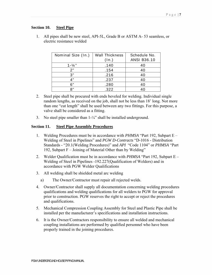
1. All pipes shall be new steel, API-5L, Grade B or ASTM A- 53 seamless, or electric resistance welded
Nominal Size (In.) Wall Thickness (In.)
Schedule No. ANSI B36.10
1-¼” .140 40 2” .154 40 3” .216 40 4” .237 40 6” .280 40 8” .322 40
2. Steel pipe shall be procured with ends beveled for welding. Individual single random lengths, as received on the job, shall not be less than 18’ long. Not more than one “cut length” shall be used between any two fittings. For this purpose, a valve shall be considered as a fitting.
3. No steel pipe smaller than 1-¼” shall be installed underground.
Section 11. Steel Pipe Assembly Procedures
1. Welding Procedures must be in accordance with PHMSA “Part 192, Subpart E – Welding of Steel in Pipelines” and PGW D-Contracts “D-1016 - Distribution Standards - “20.1(Welding Procedures)” and API “Code 1104” or PHMSA “Part 192, Subpart F – Joining of Material Other than by Welding”
2. Welder Qualification must be in accordance with PHMSA “Part 192, Subpart E – Welding of Steel in Pipelines -192.227(Qualification of Welders) and in accordance with PGW Welder Qualifications
3. All welding shall be shielded metal arc welding
a) The Owner/Contractor must repair all rejected welds.
4. Owner/Contractor shall supply all documentation concerning welding procedures qualifications and welding qualifications for all welders to PGW for approval prior to construction. PGW reserves the right to accept or reject the procedures and qualifications.
5. Mechanical Compression Coupling Assembly for Steel and Plastic Pipe shall be installed per the manufacturer’s specifications and installation instructions.
6. It is the Owner/Contractors responsibility to ensure all welded and mechanical coupling installations are performed by qualified personnel who have been properly trained in the joining procedures.
P a g e | 8
PGW UNDERGROUND HOUSE PIPING MANUAL
Section 12. Corrosion Control Requirements
1. Corrosion Control must be in accordance with PHMSA “Part 192 – Subpart I – Requirements for Corrosion Control” and PGW D-Contracts “D-1015 - General Specifications – Appendix A(Corrosion Control)”
2. Pipe Coating must be in accordance with PHMSA “Part 192, Subpart I – Requirements for Corrosion Control – 192.461(Coating)”
3. Cathodic Protection must be in accordance with PHMSA “Part 192, Subpart I – Requirements for Corrosion Control – 192.463(Cathodic Protection)”
4. Corrosion Control Devices must be installed as per manufactures instructions
Section 13. Plastic Pipe
1. Plastic pipe must be ASTM D2513 Polyethylene (PE), PE 2406.
2. Plastic pipe shall be procured as follows: All CTS pipe in coiled rolls, 1-¼” IPS pipe in 500’ coils or 40’ lengths, 2” IPS pipe in 500’ coils or 40’ lengths, 3”, 4”, 6” and 8” IPS pipe in 40’ lengths.
3. PGW reserves the right to approve and reject any plastic pipe manufacturer that PGW feels does not meet the requirements set forth above. It is the Owner/Contractors responsibility to gain PGW’s approval prior to ordering pipe and or any fittings.
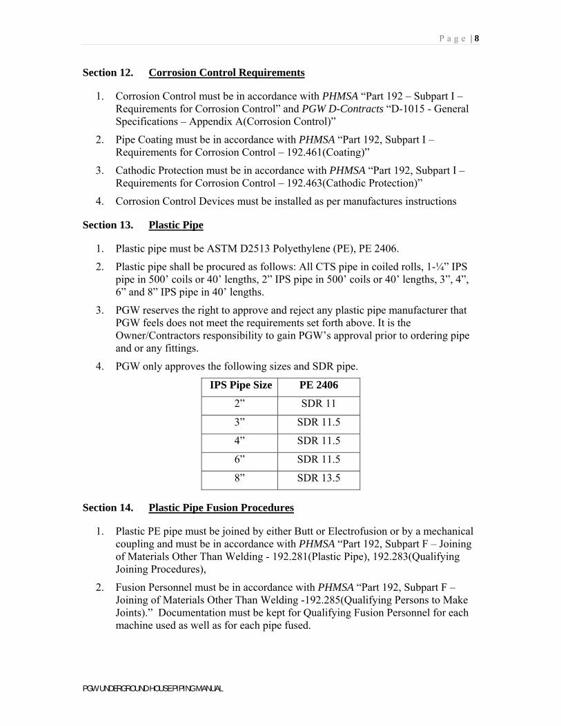
4. PGW only approves the following sizes and SDR pipe.
IPS Pipe Size PE 2406
2” SDR 11
3” SDR 11.5
4” SDR 11.5
6” SDR 11.5
8” SDR 13.5
Section 14. Plastic Pipe Fusion Procedures
1. Plastic PE pipe must be joined by either Butt or Electrofusion or by a mechanical coupling and must be in accordance with PHMSA “Part 192, Subpart F – Joining of Materials Other Than Welding - 192.281(Plastic Pipe), 192.283(Qualifying Joining Procedures),
2. Fusion Personnel must be in accordance with PHMSA “Part 192, Subpart F – Joining of Materials Other Than Welding -192.285(Qualifying Persons to Make Joints).” Documentation must be kept for Qualifying Fusion Personnel for each machine used as well as for each pipe fused.
P a g e | 9
PGW UNDERGROUND HOUSE PIPING MANUAL
a) All documentation must be submitted to PGW and PGW reserves the right to approve/reject qualification documentation. If rejected, the contractor is required to come to PGW to make qualified fusion per PGW fusion procedures. Fusion training cost will be billed to the contractor.
3. Inspection of joints must be in accordance with PHMSA “Part 192, Subpart F – Joining of Materials Other Than Welding - 192.287(Inspection of Joints)”.
a) A visual inspection shall be made of every fusion joint. Any joint of questionable appearance shall be cut out and redone. PGW reserves the right of final acceptance.
b) Owner/Contractor shall only use proper pipe fusion equipment to perform fusion. Contractor shall have all equipment documentation on hand for PGW review including pressures, hold times, and heating times.
Section 15. CSST TracPipe
1. No owner/contractor should install underground CSST without first submitting one (1) set of drawings for PGW Drawing Requirements; see “Section 05 – PGW Drawing Requirements.” The drawings will be reviewed by the Distribution Planning Section along with Field Service Section of PGW
2. Installation of Underground CSST
a) The installation of underground CSST must follow manufacturer’s installation procedures. Manufacturer’s manual must be on site for inspection.
b) After all underground CSST is installed in the trench and ready for inspection, the owner/contractor must contact PGW to schedule an inspection of CSST along with a 3 psig pressure test. The trench shall remain open until all piping is inspected and tested.
c) If the pressure test passes, the owner/contractor can continue with the backfill.
3. Backfilling of trench must be in accordance with “Section 8 - Trenching, Installation and Backfilling of the Underground System”
4. For further information and inquiries,
a) Contact Planning Section, Area Engineer
Section 16. Installation - Minor Pipe
1. Diameter ≤ 2” and Length < 100 ft.
2. All Minor Pipe must have Corrosion Control and in accordance with “Section 12 - Corrosion Control Requirements”
3. In accordance with PGW D-Contracts “D-1016 - Distribution Standards - 10.0-12.5 (All Minor Pipe Specifications)
P a g e | 10
PGW UNDERGROUND HOUSE PIPING MANUAL
Section 17. Installation - Major Pipe
1. Diameter > 2”or Length ≥ 100 ft.
2. Installation of Major Pipe must be in accordance with PGW D-Contracts “D-1016 - Distribution Standards - 13.3(3” & Larger Service Risers) and “Section 8 - Trenching, Installation, and Backfilling”.
3. All Major Pipe must have Corrosion Control and in accordance with “Section 12 - Corrosion Control Requirements”
Section 18. Leak Tests
1. Leak Procedures must be in accordance with PHMSA “Part 192, Subpart M – Maintenance – 192.723 (Leakage Surveys and Procedures)” and “APPENDIX E – Underground House Piping Form”
a) PGW must be notified by the Contractor three (3) days before a Pressure Test so that PGW can schedule a PGW inspector to witness the test.
b) The time-pressure test shall be performed after the entire underground system is complete in every detail.
2. Plastic and Steel pipe shall be tested with air 90 PSIG on the piping system, the Contractor shall, in the presence of PGW, test with soapsuds every joint, fitting, weld, fusion, and valve, as well as any other part which PGW may designate.
3. The Owner/Contractor shall properly retain or block exposed pipe ends.
4. All main valves and service valve shall be in the open position for the duration of each of these tests.
5. Any defective material discovered by these tests shall be removed and good material substituted.
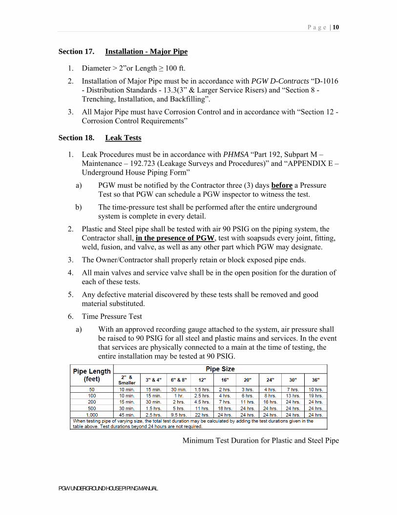
6. Time Pressure Test
a) With an approved recording gauge attached to the system, air pressure shall be raised to 90 PSIG for all steel and plastic mains and services. In the event that services are physically connected to a main at the time of testing, the entire installation may be tested at 90 PSIG.
Minimum Test Duration for Plastic and Steel Pipe
P a g e | 11
PGW UNDERGROUND HOUSE PIPING MANUAL
b) The time pressure test shall be considered as passed when a constant pressure of 90 PSIG has been plotted on the recording gauge chart for a period satisfactory to PGW but not to exceed 24 hours.
c) If at any time there is a drop in pressure indicating a leak, the test shall be disconnected until the Owner/Contractor locates and corrects the cause of the leak. The time pressure test shall then be repeated until a constant pressure reading is recorded for a time satisfactory to PGW.
d) All valves shall be operated after the final time pressure test and then left in the closed position.
7. Leaks located on any welds or fusion made by the Owner/Contractor shall be repaired to the satisfaction of PGW. Leaks located on material found to be defective shall also be repaired by the Owner/Contractor.
Section 19. Damage Prevention Standards
1. Damage Prevention must be in accordance with PGW D-Contracts “D-1016 - Distribution Standards - 53.0(Damage Prevention Instruction), 53.1(Caution Tape Installation), 53.2(Tracer Wire Installation)
Section 20. Termination of Piping
1. In accordance with PGW D-Contracts “D-1016 - Distribution Standards - 13.3(3” & Larger Service Heads)
2. No gas piping (meter, riser, etc.) can be placed within a 36” horizontal measurement from:
a) An electric meter or electrical equipment (air cond compressor unit, etc.)
b) Combustion air or fresh air intakes.
c) Any ignition source.
3. Meters cannot be placed under a carport roof, awning or an overhang larger than a standard eave.
4. Meters may be installed under operable windows only when no other options exist and is approved by PGW.
5. PGW will not approve Underground Under Building piping
6. Outside Risers or Meter Sets
a) Meters and piping must be protected from damage by vehicles by 4” diameter bollards per PGW D-Contracts “D-1016 - Distribution Standards – 53.0(Damage Prevention Instruction)”
P a g e | A
PGW UNDERGROUND HOUSE PIPING MANUAL
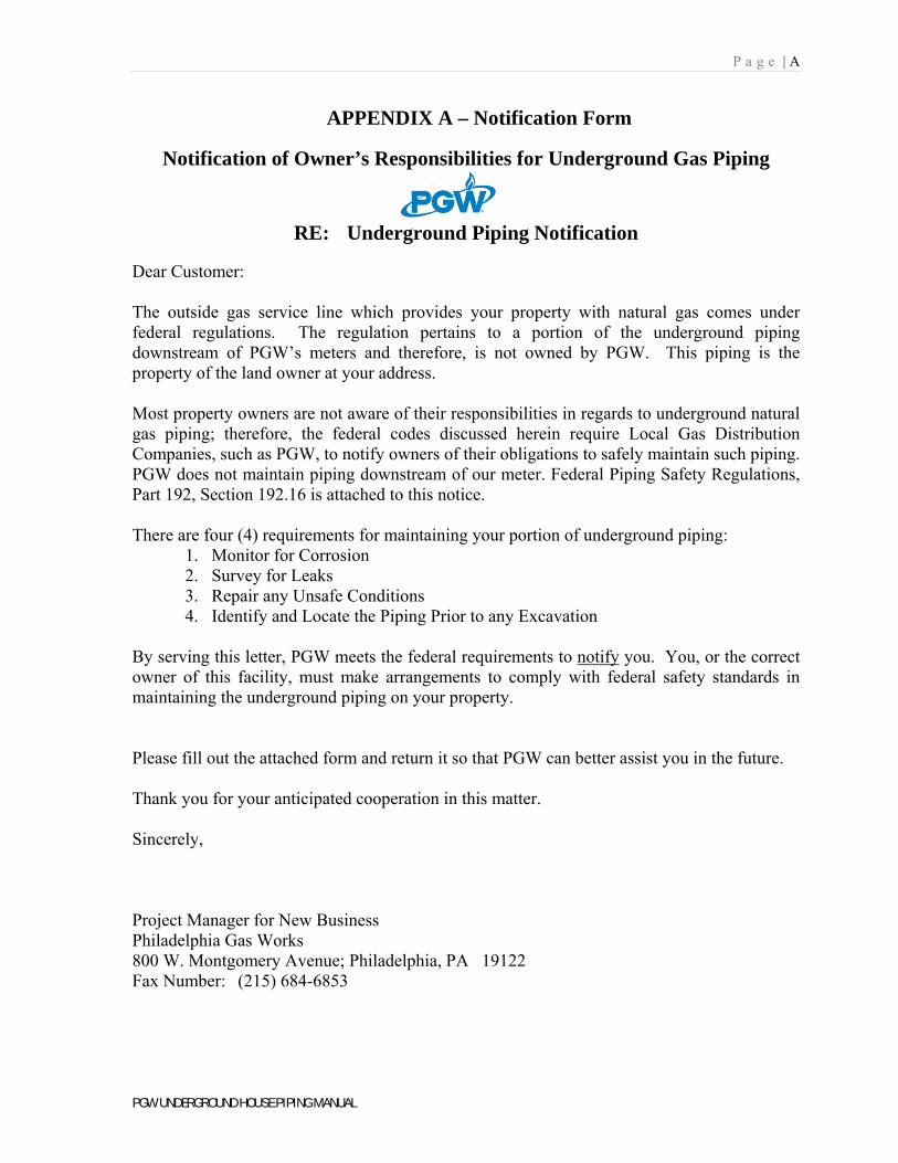
APPENDIX A – Notification Form
Notification of Owner’s Responsibilities for Underground Gas Piping
RE: Underground Piping Notification
Dear Customer: The outside gas service line which provides your property with natural gas comes under federal regulations. The regulation pertains to a portion of the underground piping downstream of PGW’s meters and therefore, is not owned by PGW. This piping is the property of the land owner at your address. Most property owners are not aware of their responsibilities in regards to underground natural gas piping; therefore, the federal codes discussed herein require Local Gas Distribution Companies, such as PGW, to notify owners of their obligations to safely maintain such piping. PGW does not maintain piping downstream of our meter. Federal Piping Safety Regulations, Part 192, Section 192.16 is attached to this notice. There are four (4) requirements for maintaining your portion of underground piping:
1. Monitor for Corrosion 2. Survey for Leaks 3. Repair any Unsafe Conditions 4. Identify and Locate the Piping Prior to any Excavation
By serving this letter, PGW meets the federal requirements to notify you. You, or the correct owner of this facility, must make arrangements to comply with federal safety standards in maintaining the underground piping on your property. Please fill out the attached form and return it so that PGW can better assist you in the future. Thank you for your anticipated cooperation in this matter. Sincerely,
Project Manager for New Business Philadelphia Gas Works 800 W. Montgomery Avenue; Philadelphia, PA 19122 Fax Number: (215) 684-6853
P a g e | A
PGW UNDERGROUND HOUSE PIPING MANUAL
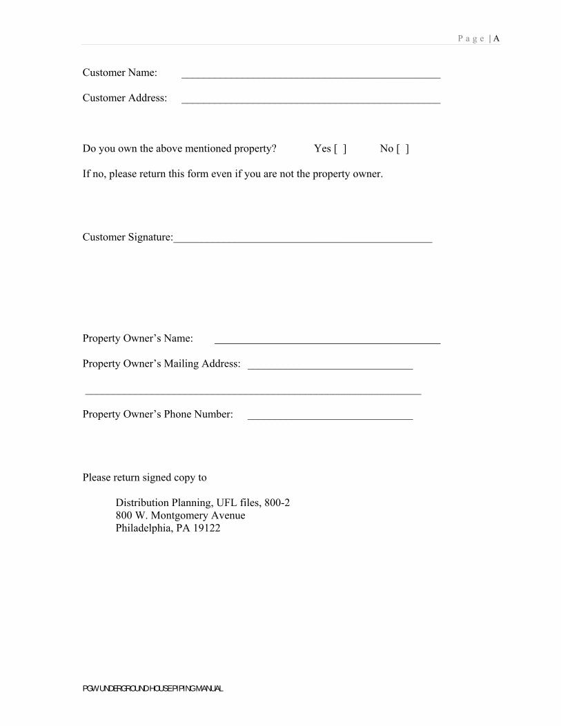
Customer Name: _______________________________________________ Customer Address: _______________________________________________ Do you own the above mentioned property? Yes [ ] No [ ] If no, please return this form even if you are not the property owner. Customer Signature:_______________________________________________
Property Owner’s Name: _________________________________________ Property Owner’s Mailing Address: ______________________________ _____________________________________________________________ Property Owner’s Phone Number: ______________________________ Please return signed copy to Distribution Planning, UFL files, 800-2 800 W. Montgomery Avenue Philadelphia, PA 19122
P a g e | B
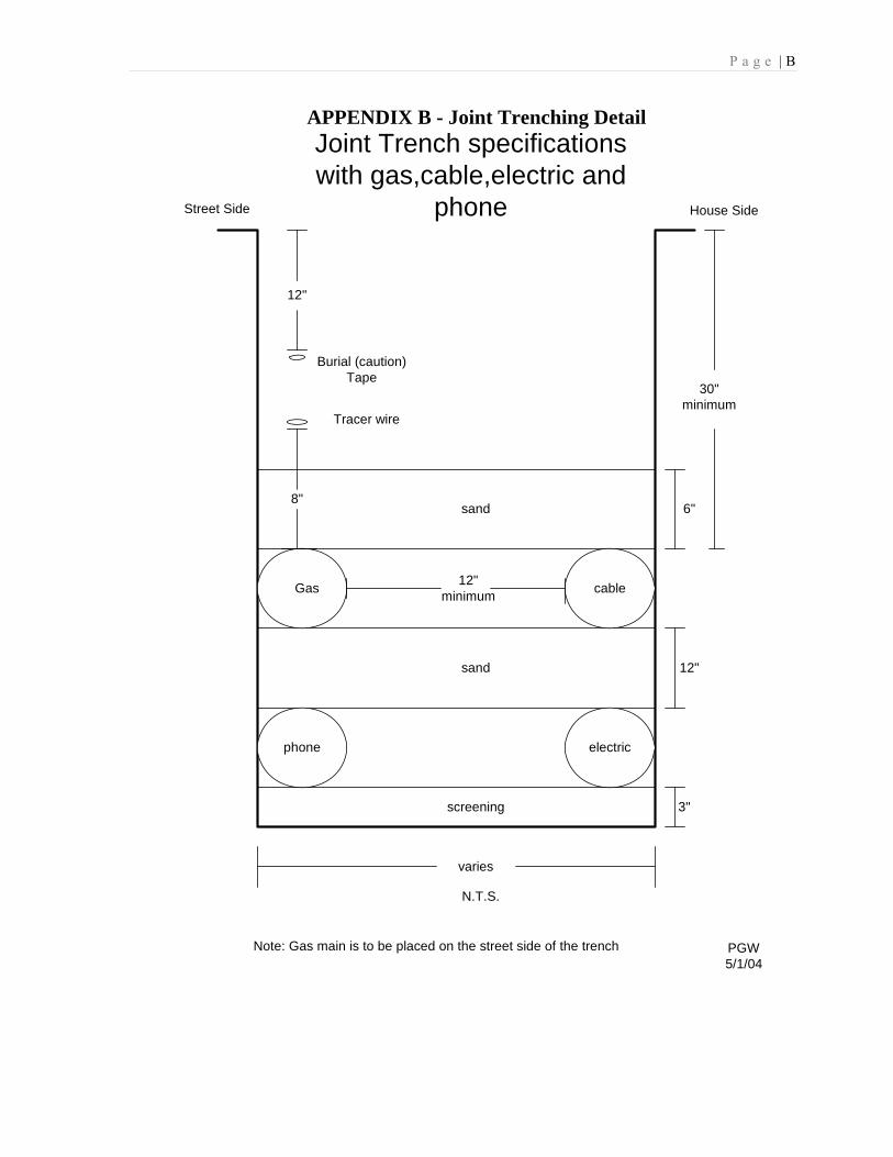
APPENDIX B - Joint Trenching Detail
Gas cable
phone electric
screening
sand
varies
N.T.S.
3"
12"
Joint Trench specificationswith gas,cable,electric and
phone
Note: Gas main is to be placed on the street side of the trench
sand 6"
PGW5/1/04
30"minimum
12"minimum
12"
Burial (caution)Tape
Tracer wire
8"
House SideStreet Side
P a g e | C
PGW UNDERGROUND HOUSE PIPING MANUAL
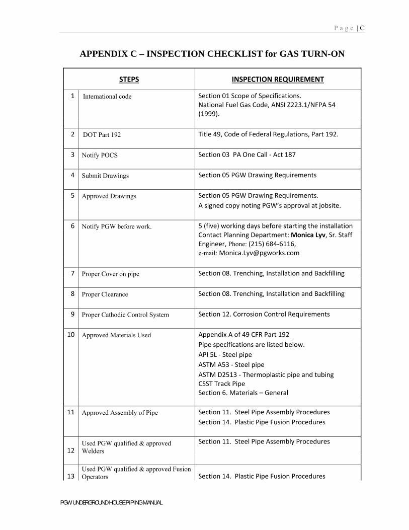
APPENDIX C – INSPECTION CHECKLIST for GAS TURN-ON
STEPS INSPECTION REQUIREMENT
1 International code Section 01 Scope of Specifications.
National Fuel Gas Code, ANSI Z223.1/NFPA 54 (1999).
2 DOT Part 192 Title 49, Code of Federal Regulations, Part 192.
3 Notify POCS Section 03 PA One Call ‐ Act 187
4 Submit Drawings Section 05 PGW Drawing Requirements
5 Approved Drawings Section 05 PGW Drawing Requirements.
A signed copy noting PGW’s approval at jobsite.
6 Notify PGW before work. 5 (five) working days before starting the installation
Contact Planning Department: Monica Lyv, Sr. Staff Engineer, Phone: (215) 684‐6116, e-mail: [email protected]
7 Proper Cover on pipe Section 08. Trenching, Installation and Backfilling
8 Proper Clearance Section 08. Trenching, Installation and Backfilling
9 Proper Cathodic Control System Section 12. Corrosion Control Requirements
10 Approved Materials Used Appendix A of 49 CFR Part 192
Pipe specifications are listed below.
API 5L ‐ Steel pipe
ASTM A53 ‐ Steel pipe
ASTM D2513 ‐ Thermoplastic pipe and tubing
CSST Track Pipe Section 6. Materials – General
11 Approved Assembly of Pipe Section 11. Steel Pipe Assembly Procedures
Section 14. Plastic Pipe Fusion Procedures
12 Used PGW qualified & approved Welders
Section 11. Steel Pipe Assembly Procedures
13 Used PGW qualified & approved Fusion Operators Section 14. Plastic Pipe Fusion Procedures
P a g e | C
PGW UNDERGROUND HOUSE PIPING MANUAL
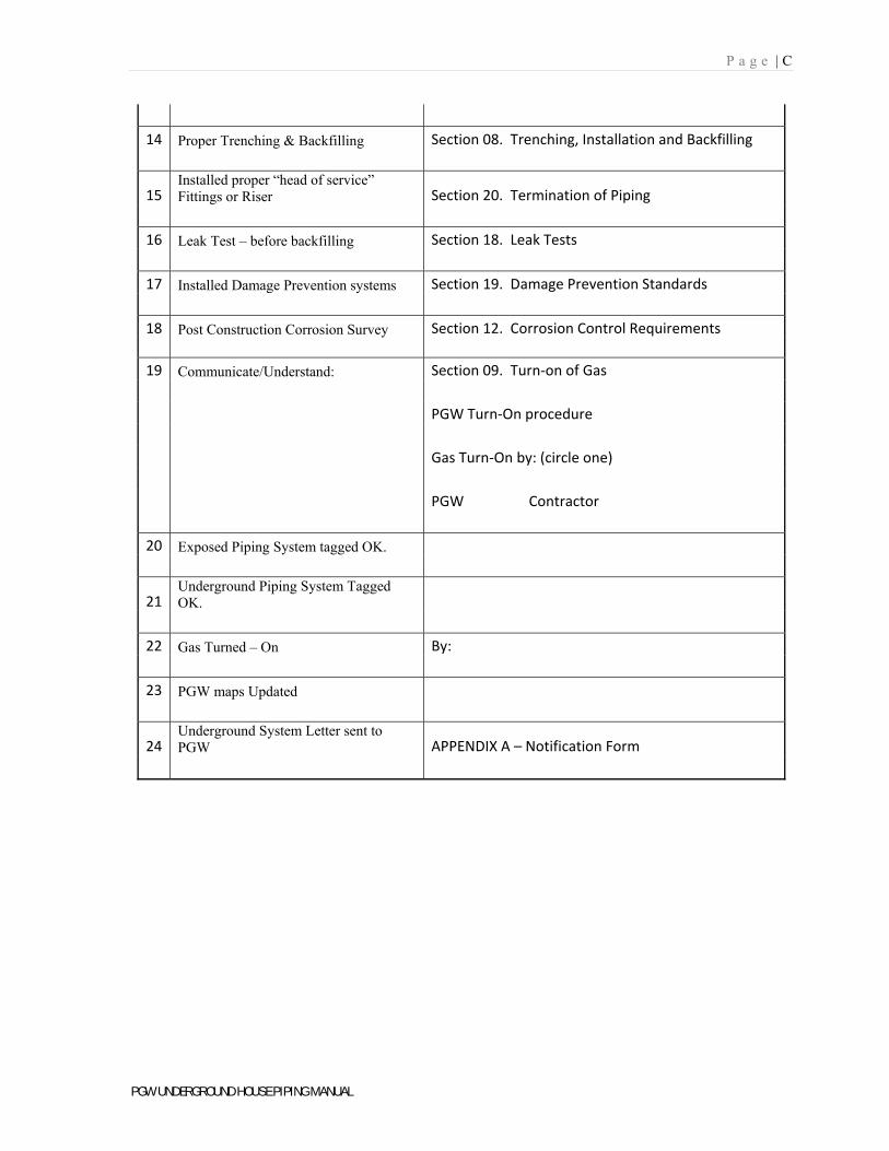
14 Proper Trenching & Backfilling Section 08. Trenching, Installation and Backfilling
15 Installed proper “head of service” Fittings or Riser Section 20. Termination of Piping
16 Leak Test – before backfilling Section 18. Leak Tests
17 Installed Damage Prevention systems Section 19. Damage Prevention Standards
18 Post Construction Corrosion Survey Section 12. Corrosion Control Requirements
19 Communicate/Understand: Section 09. Turn‐on of Gas
PGW Turn‐On procedure
Gas Turn‐On by: (circle one)
PGW Contractor
20 Exposed Piping System tagged OK.
21 Underground Piping System Tagged OK.
22 Gas Turned – On By:
23 PGW maps Updated
24 Underground System Letter sent to PGW APPENDIX A – Notification Form
P a g e | D
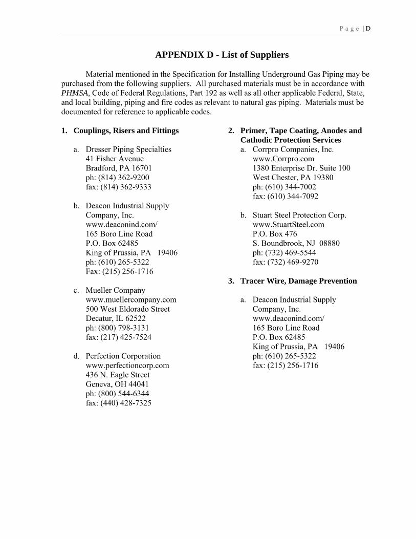
APPENDIX D - List of Suppliers Material mentioned in the Specification for Installing Underground Gas Piping may be
purchased from the following suppliers. All purchased materials must be in accordance with PHMSA, Code of Federal Regulations, Part 192 as well as all other applicable Federal, State, and local building, piping and fire codes as relevant to natural gas piping. Materials must be documented for reference to applicable codes. 1. Couplings, Risers and Fittings
a. Dresser Piping Specialties 41 Fisher Avenue Bradford, PA 16701 ph: (814) 362-9200 fax: (814) 362-9333
b. Deacon Industrial Supply
Company, Inc. www.deaconind.com/ 165 Boro Line Road P.O. Box 62485 King of Prussia, PA 19406 ph: (610) 265-5322 Fax: (215) 256-1716
c. Mueller Company
www.muellercompany.com 500 West Eldorado Street Decatur, IL 62522 ph: (800) 798-3131 fax: (217) 425-7524
d. Perfection Corporation
www.perfectioncorp.com 436 N. Eagle Street Geneva, OH 44041 ph: (800) 544-6344 fax: (440) 428-7325
2. Primer, Tape Coating, Anodes and Cathodic Protection Services a. Corrpro Companies, Inc. www.Corrpro.com 1380 Enterprise Dr. Suite 100 West Chester, PA 19380 ph: (610) 344-7002 fax: (610) 344-7092 b. Stuart Steel Protection Corp. www.StuartSteel.com P.O. Box 476 S. Boundbrook, NJ 08880 ph: (732) 469-5544
fax: (732) 469-9270
3. Tracer Wire, Damage Prevention
a. Deacon Industrial Supply Company, Inc. www.deaconind.com/ 165 Boro Line Road P.O. Box 62485 King of Prussia, PA 19406 ph: (610) 265-5322 fax: (215) 256-1716
P a g e | E
PGW UNDERGROUND HOUSE PIPING MANUAL
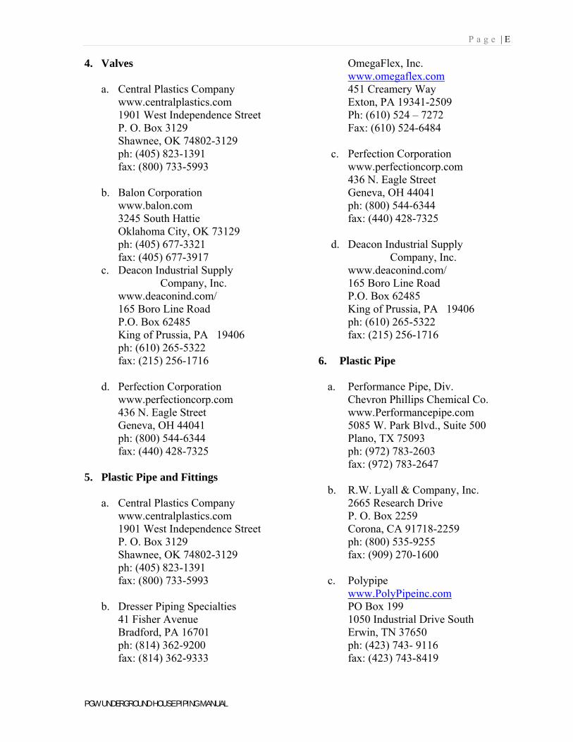
4. Valves
a. Central Plastics Company www.centralplastics.com 1901 West Independence Street P. O. Box 3129 Shawnee, OK 74802-3129 ph: (405) 823-1391 fax: (800) 733-5993
b. Balon Corporation www.balon.com 3245 South Hattie Oklahoma City, OK 73129 ph: (405) 677-3321 fax: (405) 677-3917
c. Deacon Industrial Supply Company, Inc.
www.deaconind.com/ 165 Boro Line Road P.O. Box 62485 King of Prussia, PA 19406 ph: (610) 265-5322 fax: (215) 256-1716
d. Perfection Corporation www.perfectioncorp.com 436 N. Eagle Street Geneva, OH 44041 ph: (800) 544-6344 fax: (440) 428-7325
5. Plastic Pipe and Fittings
a. Central Plastics Company
www.centralplastics.com 1901 West Independence Street P. O. Box 3129 Shawnee, OK 74802-3129 ph: (405) 823-1391 fax: (800) 733-5993
b. Dresser Piping Specialties 41 Fisher Avenue Bradford, PA 16701 ph: (814) 362-9200 fax: (814) 362-9333
OmegaFlex, Inc. www.omegaflex.com 451 Creamery Way Exton, PA 19341-2509 Ph: (610) 524 – 7272 Fax: (610) 524-6484
c. Perfection Corporation
www.perfectioncorp.com 436 N. Eagle Street Geneva, OH 44041 ph: (800) 544-6344 fax: (440) 428-7325
d. Deacon Industrial Supply
Company, Inc. www.deaconind.com/ 165 Boro Line Road P.O. Box 62485 King of Prussia, PA 19406 ph: (610) 265-5322 fax: (215) 256-1716
6. Plastic Pipe
a. Performance Pipe, Div.
Chevron Phillips Chemical Co. www.Performancepipe.com 5085 W. Park Blvd., Suite 500 Plano, TX 75093 ph: (972) 783-2603 fax: (972) 783-2647
b. R.W. Lyall & Company, Inc. 2665 Research Drive P. O. Box 2259 Corona, CA 91718-2259 ph: (800) 535-9255 fax: (909) 270-1600
c. Polypipe
www.PolyPipeinc.com PO Box 199 1050 Industrial Drive South Erwin, TN 37650 ph: (423) 743- 9116 fax: (423) 743-8419
P a g e | E
PGW UNDERGROUND HOUSE PIPING MANUAL
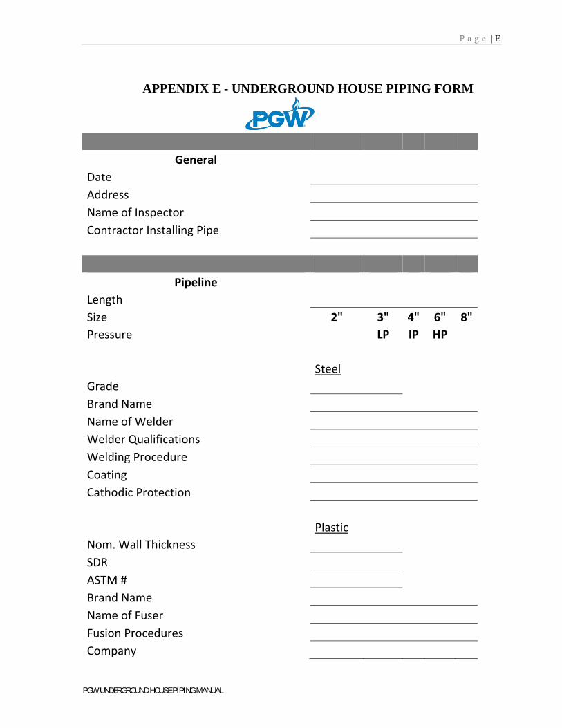
APPENDIX E - UNDERGROUND HOUSE PIPING FORM
General
Date
Address
Name of Inspector
Contractor Installing Pipe
Pipeline
Length
Size 2" 3" 4" 6" 8"
Pressure LP IP HP
Steel
Grade
Brand Name
Name of Welder
Welder Qualifications
Welding Procedure
Coating
Cathodic Protection
Plastic
Nom. Wall Thickness
SDR
ASTM #
Brand Name
Name of Fuser
Fusion Procedures
Company
P a g e | E
PGW UNDERGROUND HOUSE PIPING MANUAL
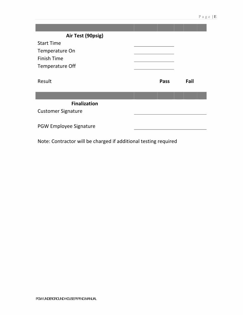
Air Test (90psig)
Start Time
Temperature On
Finish Time
Temperature Off
Result Pass Fail
Finalization
Customer Signature
PGW Employee Signature
Note: Contractor will be charged if additional testing required