Embed Size (px)
Citation preview
APAE - I15 y!&mmll AEC Reseiuch and Development Report UG$1, Replctors - Power [Speck1 Distribution]
PL-3 phase I task 3 R a D report
ALCO PRODUCTS, INC. NUCLEAR POWER ENGINEERING DEPARTMENT
DISCLAIMER
This report was prepared as an account of work sponsored by an agency of the United States Government. Neither the United States Government nor any agency Thereof, nor any of their employees, makes any warranty, express or implied, or assumes any legal liability or responsibility for the accuracy, completeness, or usefulness of any information, apparatus, product, or process disclosed, or represents that its use would not infringe privately owned rights. Reference herein to any specific commercial product, process, or service by trade name, trademark, manufacturer, or otherwise does not necessarily constitute or imply its endorsement, recommendation, or favoring by the United States Government or any agency thereof. The views and opinions of authors expressed herein do not necessarily state or reflect those of the United States Government or any agency thereof.

DISCLAIMER
Portions of this document may be illegible in electronic image products. Images are produced from the best available original document.
APAE-115 Volume 3 AEC 'Research and Development Report . . .
UC-81, Reactors, -Power (Special is t rhut ion)
PL-3 PHASE I TASK 3 R & D REPORT
G. E. Humphries, Project Engineer, PL-3
Issued: March 12, 1962
Contract No. AT(30-1)-2900 with U. S. Atomic Energy Commission
New York Operating Office
ALCO PRODUCTS, INC.. Nuclear Power Engineering Department
Pos t Office Box 414 Schenectady 1, N, Y.
AEC LEGAL NOTICE
This report was prepared as an account of Government sponsored work. Neither the United' States, nor the Commission, nor any person acting on be- half of the Commission:
A. Makes any warranty or representation; expressed o r implied, with respect to the accuracy, completeness, o r usefulness of the infor- mation contained in th is report, o r that the use of any information, ap- paratus, method, o r process disclosed in this report may not infringe .privately owned rights: o r
B. Assumes any liabilities with respect to the use of, o r for damages resulting from the use of any information, apparatus, method, o r process disclosed in this report.
As used in the above, "person acting on behalf of the Commission" includes any employee .or contractor of the Commission, or employee of such contractor, ,to the extent that such employee or contractor of the Commission, -o r employee of such contractor prepares, disseminates, o r provides access to, any information pursuant to :h i s employment o r contract with the Commission, o r his employment with such contractor.
ALCO LEGAL NOTICE
This report was prepared by Alco Products, Incorporated in the course of work under, - or in connection with, Contract No. AT(30-I) -2900, issued by U. S. Atomic Energy Commission, NYOO; and subject only to the rights of the. United States, under the provisions of this contract, Alco. Products,' Incorporated makes no warranty or representation, ex- p re s s o r implied, and shall have no liability with respect to this report or any of its contents o r with respect to the use thereof o r with respect to whether any such use will infringe the rights of others.
DISTRIBUTION
External Copies
1 - 2 New York Operations Office . . . . . . . . . . U. S Atomic Energy Commission :. . . . .
c/o Alco Products, Inc. . . . . . : , .
1 -Nott Street ..
Schenectady 5, New:York. . . . . '
Attention: Resident 'Engineer,' PL-3 . . . .
3 - 4 New York Operations Office . . . . U. So Atomic Energy Commission 376 Hudson Street New York 14, New York
Attention: Project Engineer, PL-3 , '
. . . Reactor Division' - , . .
. . . 5 - 9 U. S. Atomic Energy Commission Washington 25, D. C.
.- . . .
Attention: Chief, Water Systems Branch . . . .
(Army Reactors) Division of Reactor Development
. Mail Station F-311
10 U. S. Atomic Energy Commission Washington 25, D. C. . . . .
. .
Attention: Chief, Water Reactors Branch, . . . . . . -
Civilian Power . x .. . Division of Reactor Development Mai1.Statio.n F-311 - *
. .
U. S. Atomic Energy Commission Chief, New York Patent Group Brookhaven National Laboratory Upton, New York
Attention: - Harmon Potter . , . . .
iii
DISTRIBUTION (CONT'D)
External Copies
.12 U. S. Atomic Energy Commission Olfice'of the General Counsel Washington 25, D. C.
Attention: Mr. Roland Aqderson
13 U. S. Atomic Energy Commission Idaho Operations Office P. 0. Box 2108 Idaho Falls, Idaho
Attention: Director,. Divisiod .of ~ i l i t a r y Reactors
1'4 U. S. Atomic Energy omm mission Reports and Statistics Branch Division of Reactor Development Washington 25, D. C.
15 - 19 Bureau of Yards and Docks Navy Department
. . Washington 25, D. C. . .
Attention: Director, ~ u c l e a r Power Division Code E-300
20 Office of the Chief of Engineers . .
Department of the Army Building T-7 Washington 25, ,D. C.
Attention: , Chief, Projects Branch Nuclear Power 'Division :
Nuclear power' Field office U. S. Army Engineer Reactors Gro'up Fort. Belvoir, Virginia . ,
Attention: Chief, Nuclear Power Field Office
External I Copies
22 Sundance Air Force Radar Station P.O. Box 80 . . '
Sundance, Wyoming -. : .'
~ Attention: AEC Representative,, PM-1 # . : . ..,
23. . Nuclear Power Field Office . : . . " _ . , ..
U. S. Army Engineer Reactors Group For t Belvoir, Virginia . . . . . . .
. . . . . . , ...
Attention: 0. I. C. SM-1 _ .
. I _ .
24 Chief, U.S. Army Reactors Group For t Greeley, Alaska APO 733 Seattle, Washington . .
. : - . . . ' . .
Attention: 0. I. C. SM-1A ,: ..-
. . . . . . . .
25 Commanding Office U. S. Army Polar Research and Development Center:,. For t Belvoir, Virginia
. .
Attention: Nuclear power Officer ,. . . . . , . . . . . . . , . . . .
... 26
. . Commander . . .
Air' Force Special Weapons Center (AFSWC) ' . . . .
Albuqerque, New Mexico
Attention: SWVP . . , . . . . . . . . . . . . . . ,
27. - 29 . Office of Technical Information Extension . ' . . . P.O. B0x.62 . .
Oak Ridge, Tennessee . . . . .
30 Union Carbide Nuclear. Corporation . - . , ,
Oak Ridge National Laboratory Y-12 Building,9704-1 . .
. . . . . . . . . . P. 0. Box "Y" . .
. . . . . . c . . .
. . . . Oak Ridge, Tennessee
. . , . . . . . . . . . . . . . . , . .
Attention: Mr. L. D. Schaffer . . . . . . . ' .% . .
v
Externa l Copies
31 Di rec to r - I
U. S. Army Cold Regions -
R e s e a r c h and Engineering Labora tor ies P. 0. Box 282 Hanover, Ne-w Hampshire
. . .
Attention: Dr . R. W. Gerde l
Advanced Technology I,ahnra toriee . Division of American-Standard 369 Whisman Road Mountain View, Cal i fornia
Attention: Di rec tor , Resea rch and Development
Aeroject Genera l Nucleonics Mil i tary Products Division Bux 77 San Ramon, California
t
Attention: ' -Manager . . .
The Babcock & Wilcox Company Atomic Energy Division 1201 Kemper S t r e e t P.O. Box 1260 Ly nchburg, Virginia
. .
Attention: Manager
Combustion Engineering, Inc. Nuclear Division P r o s p e c t Hill Road Windsor, Connecticut
Attention: M r . J. B. Anderson .
Genera l Atomic Division of Genera l Dynamics P. 0. Box 608 San Diego 12 , California
Attention: Ass i s tan t Laboratory Di rec to r
., .. . . . .,I - .. .. %. . .
. .. . . ', ;. Exte rna l . . . : i . . i ' : , . . . . . . . ? Copies . , . .. . .
37 G e n e r a l E l e c t r i c C o m p a n y . '
Atomic Power Equipment 2151 South First S t r e e t San J o s e 12, Cal i fornia
Attention: Manager , Engineering .. .
. . Lockheed-Georgia Company . . .. r
Lockheed Nuclear Produc ts Mar ie t ta , Georgia ,. . . . .:
Attention: D i r ec to r , ~ u c l e a r ' Labora tor ies : . ..
b
The Mar t in Company , .
P. 0. Box 5042 . ., ~ i d d l e River , Maryland . . .
.- . . . .. , .
Attention: AEC Cont rac t Document Custodian ."
United Nuclear Corporat ion . . ...
Developnlent Division . . .
5 New S t r e e t White P la ins , N. Y. . .
. . _ Attention: L ib ra ry Custodian . . .
. , . ., .
Westinghouse E lec t r i c Corporat ion Atomic Power Depar tment P.O. Box 355 P i t t sburgh 3 0, Pennsylvania
Attention: D i r ec to r of P r o j e c t s
In te rnuc lear Company 7 North Brentwood Blvd. Clayton 5, Mis sou r i
Attention: M r . 0. J. E l g e r t
In te rna l Copies
DISTRIBUTION (CONT' D) -
Jackson- and orel land. Company Park-Square Bldg; . .
Boston 16, Massachuse t t s
Attention: M r . Harold Vann
. . .
W. D. .-Leggett K. Kasschau J. G. Gal lagher J., F. Haitles G. E . -Humphries N. F. Taylor , .
J. H. Mackin D, G. Ot t J. W. Niest l ie W. R. P e a r c e E. R. Schmidt P. E. Bobe W. 0. Enright R. E. Wil l iams E. L. Cofrances R. M. Ryan H. N. Rober t s
61 - 75 NPED File
ABSTRACT
This r e p o r t s u m m a r i z e s the r e s u l t s of r e s e a r c h and development t a sks per formed during. Phas.e I of this contract .and presen ts : recommendations f o r future .development-.work.: Work is r e p o r t e d in the areas;of plant assembly and -reloeation', ' .housings and footings, 'waste-.heat dissipation, instrumentation, refueling. s y s t ems , waste. d isposal , shielding, c o r e nuc lea r t he rma l and hydraulic s tudies; gaseous waste process ing (BWR), and c r i t i ca l exper iments on a 5 x 5 a r r a y of Type 3 fuel e lements .

T H I S PAGE
W A S INTENTIONALLY
L E F T BLANK
TAB.LE O F CONTENTS
. . P a g e
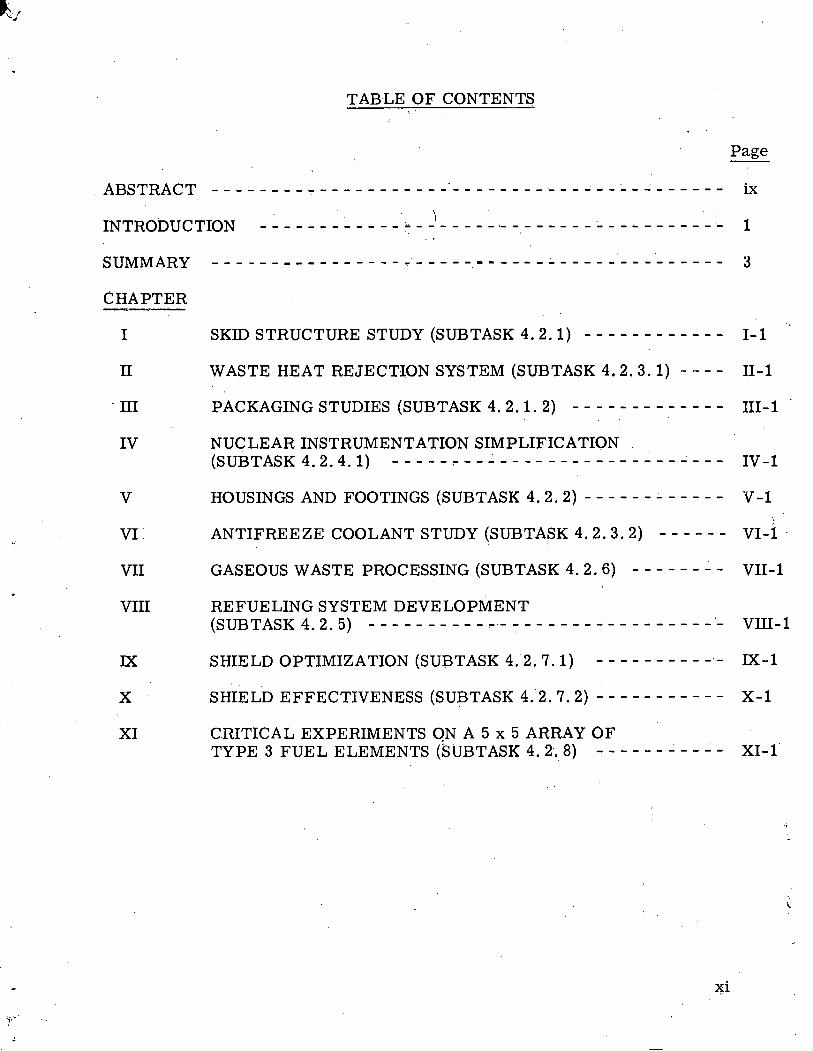
CHAPTER - I SKID STRUCTURE STUDY (SUBTASK 4.2. I ) - - - - - - - - - - - - 1- 1
n WASTE HEAT REJECTION SYSTEM (SUBTASK 4.2 .3 . 1 ) - - - - 11-1
v
VI' :
VII
VIII
PACKAGING STUDIES (SUBTASK 4 .2 .1 .2 ) - - - - - - - - - - - - - . .
111-1 :
NUCLEAR INSTRUMENTATION SIMPLIFICATION (SUBTASK 4 .2 .4 .1 ) -----:-- 1- - - - - - - - - - - - - - - - - - - Iv-1
HOUSINGS AND FOOTINGS (SUBTASK 4 .2 .2 ) - - - - - - - - - - - - V-1
ANTIFREEZE COOLANT STUDY (SUBTASK 4 .2 .3 .2 ) - - - - - - VI-1 .
GASEOUS WASTE PROCESSING (SUBTASK 4 .2 .6 ) - - - - - - - - VII- 1
REFUELING SYSTEM DEVELOPMENT (SUBTASK 4 .2 .5 ) - - - - - - - - - - - - - - - - - - - - - - - - - - - - - - VIII- 1
M - 1 SHIELD OPTIMIZATION (SUBTASK 4 . 2 . 7 . 1 ) - - - - - - - - - - -
SHIELD EFFECTIVENESS (SUBTASK 4 .2 .7 .2 ) - - - - - - - - - - - X-1
XI CRITICAL EXPERIMENTS ON A 5 x 5 ARRAY O F T Y P E 3 F U E L ELEMENTS (SUBTASK 4 .2 .8 ) - - - - - - - - - - - XI-1

T H I S PAGE
W A S INTENTIONALLY
LEFT BLANK
LIST O F F.IGURES
Page Figure Ti t le - Skid Package Using Fabr i c Mater ial Over Light Fr arne
Skid Package Using Panel Mater ial Over Light F r a m e
Approximate Decay After S c r a m
Operating Ranges of Nuclear Instrumentation Including Effect of Gamma Flux
Byrd Station Snow Densification Date f rom 1960 Surface
Comparison of Shipping Weights and Volumes of Spread Footing Members V-25
V-26
V-27
V-28
VIII- 6
VIII- 7
VIII- 8
Building Superstructure Design Cr i t e r i a
Building Superstructure Insulation Study
Typical Cam Locked Joint v - 5
VIII - 1
VIII - 2 . .
VIII-3
VIII - 4
Refueling Concept Using Trans fe r F la sk
Spent Fuel Chute Concept
Shielding Requirements for Shipping'the Reference Core
Shipping C a s k Shield Reduction fo r a partial Reference Core VIII- 9
VIII- 5
M-1
M-2
XI-1
Attenuation Curves f o r Reference C o r e
Gamma Dose Rate Vs. Distance F r o m Centerline of Core
Lead Thickness Vs. P r i m a r y ghield ~ a d i ' u s I
Positioning of a 5 x 5 A r r a y of Type I11 Elements: 5 Control Rod Core for PL-3 Mockup
Four Rod Cr i t ica l Bank Position Vs. Grams B-10 in a 5 x 5 ~ r r a y of Type 3 Elements
xii i 1
Figure Ti t le
XI-3 Five Rod Cr i t ica l Bank Pos'ition -Vs. Grams B-10 in a 5 x 5 Ar ray of Type 3 E lemen t s
XI-4 Four Rod' Bank Worth :Vs.. Cr i t ica l Bank Posit ion in a '
5 x 5 Ar ray of Type 3 Elements
Page " :
xr-16
XI-5 Five Rod Bank Worth Vs. F ive Rod Bank posi t ion in a 5'x 5 Ar ray of Type 3 Elements . . . XI-18
. .
XI-6. Rod A Worth Vs, Rod A Posit ion in a 5 x 5 A r r a y of Type.3 Elements XI -1 9.
XI-7 Average Core Tempera ture Vs. the Posit ion of ~ o d ' ~ in a 5 x 5 A r r a y of Type 3 Elements XI-20
I xiv
LIST OF TABLES
Table , - Title
' 1-1 Limits of Low Temperature Application of Construction Materials
Ti 1-2 Limits of Low Temperature. Application of Metals
i 111-1 Summary of Environmental Conditions Expected During ~ r a n s ~ o r t a t i o n of PL-3 ' ~ o d u l e s
, 111-2 Comparison of Packaging for Existing Plants
111-3 Estimated Package Weights in Pounds for 'Panel Materials
. .
.:VI - 1 Coolant Properties _ .:.. . , . . .
VIII - 1 : PL-3 Shipping Cask Data Sheet
1 . IX-1 Reactor Configurations and Conditions of Operation
1 XI-1 5 Rod Bank Calibration
XI-2 4 Rod Bank Calibration
XI-3 Calibration of Rod A
; XI-4" Temperature Coefficient Measurements
XI- 5 Temperature Coefficient Measurements
XI-6 ' Reflector Worth Measurements
XI-7 Reflector Worth Measurements
XI-8 Stuck Rod Measurements
' XI-9 Stuck Rod Measurements, No B-10
,XI-10 Reactivity Difference
Page
1-9
111- 6
v1-3
VIII- 5
M - 2
XI -'5
XI- 6
x1-$7
XI- 8
XI- 9
. . . . . INTRODUCTION. . . . . .
I . ..
Under Task 3 of Phase I of Contract AT(30-1)-2900, Alco Products performed studies to develop improvements to present portable nuclear power plant designs, directed specifically toward fulfilling the rigid environmental, schedule and logistic requirements involved in installation and operation of the PL-3 plant at Byrd Station, Antartica. These studies consisted of design and development areas universally applicable to BWR and PWR plants and some specific to one of the plant concepts.
The universal development areas were plant assembly and relocation, housings and footings ,, waste heat dissipation, instrumentation, . refueling systems, waste dispos'al and shielding. Individual development areas involved core nuclear thermal and hydraulic studies for each type of plant and gaseaou waste processing for the BWR concept. In -addition a critical experiment was performed on a 5 x 5 a r ray of plate type, Type 3 fuel e1ement.s.
,. : -. ,
This. report summarizes the results of these tasks and presents recom- mendations for continued development work during phase I1 of this contract.
Some of.the major results of this development effort are: .:. . p
. . .
1. Skid and module weight and size have been optimized to meet the r e - quirement of a i r transportability for the entire plant. ..
. . 2. A reliable waste heat rejection system has been developed to meet :: ... . the extreme climatic' conditions.
3. Packaging techniques have been optimized to give maximum protection consistent with weight and cost:
4. Studies 'of various. housing and footing designs and construction materials have resulted in reduction in weight, cost and erection time.
5. Gaseous waste processing studies have produced several suitable methods for handling radioactive gases for BWR and PWR plants.
6. Refueling system development effort has resulted in a simplified fuel handling technique requiring fewer and lighter spent fuel shipping casks.
7. Shielding studies have identified combinations of shielding nlaterials and configurations resulting in an overall reduction of shielding weight. .
Advanced shielding codes applicable to PL-3 have been identified and will be used during the final design.
- A resume of the recommendations fornew o r continued development work under fo ask ,4 of Phase I1 follows::
. . . . . . . . . . . . . . ,. .. . .
1. Study ,. analysis and verification testing of-s hielding- conf igurations .
should be.-continued.-in-Phase.11 in order to-further optimize.the shield- ing arrangement, reduce weight and decrease erection time.
. . . . . . . . . . . . . . . - . . . . . . , . . . . . . . . . .
. . ...
2. Critical mock'up experiments and-analysis s-hould be performed to . .
provide. detaikd..power .distributions, .,control rod calibrations, . . .
temperature coefficient and defect, reflector and material worths:. '' . . . - . . . . . . _ .
3, Zero power experiments and analysis will be performed on the two as-fabricated cores to .determine stuck rod positions, core loading procedures, critical bank positions and calibrations ..
., . . .
4. A full scale flow test w i l l be performed to determine or i f ices izes , channel flow rates and velocities, and to measure pressure drops.
5. Gas,eous waste disposal development should be continued to develop a method of working over the spent fuel pit and reactor shield tank while handling ruptured fuel emitting fiission product'gases.
6. A se r ies of.packaging materials tests should be conducted to'determine the most suitable material for this service.
. .
7. Reactor vessel. material samples should be prepared. for irradiation surveillance, tests in the PL-3 reactor.
SUMMARY
The research and.development studies accomplished during Task 3. of . .
Phase , I . a re briefly summarized below., .Further details' a r e inc1ud;ed in the respective chapters of this report, and in'separate topical reports.
. . . .
I Skid Structure Study - (Subtask 4.2.1) . . . .
This study was-undertaken to determine the most suitable material and design of skid structure for -PL-3 application. The study concluded that T-1 steel (U. S. Steel Corporation) was best suited for this application, from a stand- point of weight, strength at low temperature, and cost. For maximum module package weight of 20,000 lb, a maximum skid length of 20 f t was determined to be optimum.
I1 Waste Heat Rejection System (Subtask 4.2.3.1)
Because plant waste heat must be ultimately dissipated to a i r , this study was performed to determine the most reliable and compact system. The study concludes that an indirect cycle, glycol - coupled condenser and air blast cooler is best suited for this application.
I11 Packaging Studies (Subtask 4.2.1.2)
A study of packaging techniques.was undertaken to determine the most suitable method of packaging PL-3 equipment and modules to assure maximum consistent with weight, cost, and environmental conditions. The study con- cludes that two methods of packaging appear suitable:'
1. Synthetic fabric covering over a light metal frame. . " .
. .
2. Stiff panel covering over a light wooden frame.
The report recommends that a program of material . . tests be performed during Phase 111.
. . .
,IV Nuclear Instrumentation Simplification (Subtask 4.2.4.1)
The objective was tosimplify nuclear instrumentation by eliminating one o r more channels'of instrumentation. . The study concludes that it .& feasible to. ' ' .
simplify this.-instrumentation but to do-so; -an extensive researc.h andtest program would' be required.: Because of schedule considerations,' this could not be accomplished under the PL-3 program. It is recommended, that a research and test program be carried out to benefit future projects under a separate R & D. '
contract.
- . . . . ' SUMMARY. (CONT' D)
V Housings and Footings (Subtask'4.2'. 2) . - . .
Jackson and. Moreland, -1nc; under -subcontract t o .Alto Products per formed prel iminary-design s tudies during -Phase I cover ing analysis of housings and. . . .
footings', . foundati0.n leveling and tunnel.' cooling. The ana-lyses investigated avail - able. ma te r i a l s and 'methods, and ' resul ted in the following pre l iminary recom-: mendations :
... > . .
1. St re s sed sk in wood panels a r e p r e f e r r e d f o r building construction. .
Meta-1 siding and plas t ic faced s t r e s s e d sk in panels offer a l ternat ive choices ,
. . .
2. Posi t ive vapor barriers should be installed at the in te r ior su r f ace of wal ls and ceiling.
3. Jo in t s between building panels should b e gasketed tongue and groove joints.
4. The minimum panel thickness should be 4 in. based on insulation requi rements .
5. Foundation leveling .sho.uld be accomplished by ,el ,ectrically ppe:r,ated s c r e w jacks u n d e r the p r i m a r y buildings and conventional building jacks under the secondary buildings.
6. Ai'r wel ls should be used:for tunnel cooling't'o maintain tunneilii . , . '. . . , ternperatuies at -80'~. -
Continuing work a t Jackson & Moreland, Inc. is concerned with f inal design and procuremerlt of mate ia l s f o r buildings, foot.ings and tunnel cooling.
VI Antifreeze C:ooIant' Study (Subtask 4 .2 .3 .2)
1 This study consisted of a l i t e r a tu re s e a r c h and manufacturer su rvey to find . a possible subst i tute ant i f reeze solution fo'r the ethylene-glycol present ly being
considered f o r the PL-3 heat re ject ion sys tem. The study disclosed s e v e r a l solutions which offer improved stabil i ty in medium and high radiation s e r v i c e s u c h as might be encountered in a BWR plant, but offer l i t t le o r no advantage in a PWR plant. The s tudy recommends ' continued investigation of radiation effects on glycol solution during Phase 11.
VII Gaseous Waste P roces s ing (Subtask 4.2.6)
The s t r ingent res t r ic t ion on release of radioactivity in the Antarct ic requi red development of a re l iab le gaseous was te process ing s y s t e m 'for the PL-3 plant. During this t ask a s y s t e m was- developed to cpntinuously p roces s the BWR plant concept was te g a s e s during no rma l and a b n o r p a l operation. A method of collecting
SUMMARY. (.CONT'.D)
and containing radioactive waste gases during refueling 'operations h a s a l s o developed for the PWR condept; This study .ind'icates that additional develop- ment work should be carried out during Phase I1 to optimize and verify results of thi.s task.
. . ? '
. ..
',' VIII Refueling Sys tem Development (Subtask 4.2.5) . . . .
- ' This. task was undertaken to simplify fuel handling, minimize weight'and , decrease refueling time. A study and evaluation of existing refueling. systems . ,
-kas conducted which resulted i n the following conclusions : .. .
1. For PWR plants the fuel transfer' chute arrangement is recommended. . .
2. For BWR plants the fuel transfer flask arrangement is recommended. . .
. 3. Fo r both plants, it is recommended that spent fuel be stored in the fuel shipping casks located in the peripheral shield tanks.
IX Shield Optimization (Subtask 4.2.7.1)
The objective was to develop shielding concepts which would produce safe and reliable shielding with minimum shipping weight and maximum ease of con- struction a t the site. The studies pursued thus f a r indicate that less shielding weight is involved in . a lead-water shield than in a steel-water shield. Further- more, a range of shield configurations which calculations indicate a r e adequate, have been determined. It is recommended that continuing effort in the a r ea of shield optimization studies (Subtask 4.2.7.1) and experimental evaluation of shielding effectiveness, (Subtask 4.2.7.2) be performed as part of ,Primary Shielding Studies under Task 4 of Phase 11. It is also recommended that shield verification testing be performed under Task 12 of Phase 11.
X Shielding Effectiveness- (Subtask 4.2.7.2)
The objective was to evaluate available data and generate new data for evaluation of the effectiveness of various shielding materials and various material- combinations, for utilization in the P,L-3 .shield design. A survey of shielding codes has been made to determine the best codes available for shielding calculations. A .survey of facilities .capable of performing shielding experiments was completed and the most desirable facility, based on PL-3 requirements, selected. Continuing effort in this a rea is recommended, as noted' above.
SUMMARY (CONT'D)
XI Critical Experiments on .a 5 x 5 Array. of Type 3 . . . ' . Fuel .Elements (Subtask 4. 2. 8) -
A 5 x 5 core containing Type 3 (SM-2) fuel elements was investigated dur- ing Task, 1 of Phase I in an effort to develop a core of minimum weight, . size and cunlplexity. Unfortunately, experimental nuclear data available on a core this size was limited, in adwtion severe limitations were impos ed.on extrapolation of data obtained from .measurements performed on larger size cores. Thus, . limited critical mock-up experiments were performed on a 5 x 5 array of Type 3 fuel elements. These experiments indicate that the 5 x 5 arrangement would be:. adequate for the PL-3 plant, but this arrangement was dropped from further con- sideration due to i ts present status of development and the tight PL-3 schedule. It is recommended that development work be continued on this core for possible application in future reactor designs, under a separate development contract.

. .
CHAPTER I SKID STRUCTURE STUDY (SUBTASK 4.2.1)
A. Treiss . .
. > . .
1 . 0 STATEMENT AND DISCUSSION OF TASK
During initial installation and subsequent relocations of the plant, it is essential that individual modules can be handled safely, rapidly and efficiently with a minimum of construction equipment. Accomplishing these objectives and anticipating severe conditions of climate and terrain will require careful attention to skid design details. The requirement that provision be made for plant re- location to another Antarctic, site after a period of operation introduces additional considerations in the design, Skid designs will be standardized to the greatest extent possible, especially forlifting, tiedown and handling devices o r attach- ments.
2 .0 OBJECTIVES O F TASK . - $ .
The objectives of this study a re to evaluate skid structure designs, cost and materials and to make recommendations for minimizing the weight of the skid structures for the PL-3 nuclear power plant.
3 . 0 -- DESCRIPTION OF WORK
The guidelines imposed by .the AVC on the design and construction of the PL-3 nuclear power plant, destined fo; installation at Byrd Station, Antarctica, place heavy emphasis on selecting skid designs and materials which minimize the .weight of the structure, thus establishing weight savings which can be applied to module equipment.
Preliminary investigations evaluated:
1. Existing skid structure.
2. Design guidelines. , . .
3. Lightweight construction mate~i .a ls and cryogenic applications.
4. Cost and weight relationships of various materials. , ..
Existing Skid S t ruc tu re s
Skid s t r u c t u r e s used for previously constructed portable nuclear power piants ..may b e classified. as e i the r pallet-type o r t r u s s type. Each type' of skid s t r u c t u r e has its advantages and disadvantages.
. . .
The t tuss - type skid s t r u c t u r e is charac te r ized by a rela t ively light pla t - f o r m to which t r u s s e s are fastened to provide neces sa ry s t rength during ship- ment . The t r u s s e s a l s o provide an easy means of attaching covering ma te r i a l , but this design is heavier than the o the r s considered. Originally, the design was intended to s a v e weight; the t r u s s e s w e r e to be used f o r suppor t of piping, wir ing and equipment. It h a s been found imprac t ica l t o use t r u s s e s f o r equip- m e n t suppor t because they hinder equipment operat ion and maintenance. T r u s s - type sk ids cannot be moved or handled without the t r u s s in place. Compress ion stresses are developed in s t r u c t u r a l m e m b e r s under dynamic loading conditions and location and at tachment of lifting and tie-down devices becomes a complex problem.- Even with the shal lower main beams allowed by the t russ- type skid, the cos t of construction is significantly higher than f o r o the r skid designs.
The pallet-type skid is charac te r ized by a rela t ively heavy plat form s t r u c t u r e using deep s ide beams to oMain the s t rength required' f o r dynamic load- ing conditions. The skid is easier and less cost ly to cons t ruc t and provides ample room f o r attachment of lifti'ng. and tie-down devices. Pro tec t ive covering may be eas i ly applied o v e r a light conduit f r a m e fastened t o the main skid beams.
Skid designs investigated were :
PM-1 PM-2 PL-1 PL-2 PM-2A PM-4A Advanced Unattended Power P lan t
' ~ a r f i n Company Mar t in Company Combustion Engineering Conibus tion Engineering Alco Alco
, . .
Alco
The skid designs could b e readi ly c lass i f ied as t russ- type (typical of P L - 2 & PM-1) o r pallet-type (typical of PM-2A).
3.2 Design Guidelines
~ PL-3 skid design guidelines have been defined as follows :
~ 1. Sub-surface plant installat ion in cut-and-cover tunnels.
2. Tranporta t ion in pre-assembled modules by C-130 a i r c r a f t operat ing under Antarct ic conditions.
3, The volume and weight of the skid and equipment should be a t a minimum (see below).
4. Design life of 20 years.
5. Field welds shall be minimized and limited to seal welds.
6. Shippings requirements.
.Modules - To facilitate handling, shipping erection and inter- a * --- connection, each assembled module shall have a rigid base.
b. -Module Statistics - The normal, maximum, allowable package shall be equal to o r less than 8' x 8' x 30" and weigh.'20,.00 lbs o r less. No module shall be larger than 8' 6" x 8' 6" x 30' o r weigh; in excess of 30,000 lbs . It may be allowable to have one package to the latter dimensions and weights. A C-130A airplane can take a 'cargo load of 25000 lbs; a C-130B, 35000 lbs. However, fuel load and structual load factors in Antarctic conditions impose limits on aircraft capacity.
c. Thrust Loadings - The magnitudes of permissible thrust loadings a r e tabulated as follows:
8 G - Forward (emergency landing)
8 G - Aft (flight)
3 G - Vertical (flight)
1. 5 G - Lateral (flight
9 G - Maximum (vector sum foward, vertical and lateral loading)
d. Packaging - Packaging shall be constructed to withstand handling, shipping ind storage in transit and a t the site. Duration of on-site storage is one year. Heating during transportation and storage should be avoided.
Materials - Materials selected should minimize the danger ,of - e. -.-- brittle fracture under all environmental conditions to be encountered. :
7. Environmental data is as follows:
~ a x i m u m temperature for plant design ' .
Minimum temperature, Antarctic conditions Static (storage) Dynamic (transport)
I 3.3. Lightweight Construction Mater,ials . .
3.3.1 Materials Investigated . "
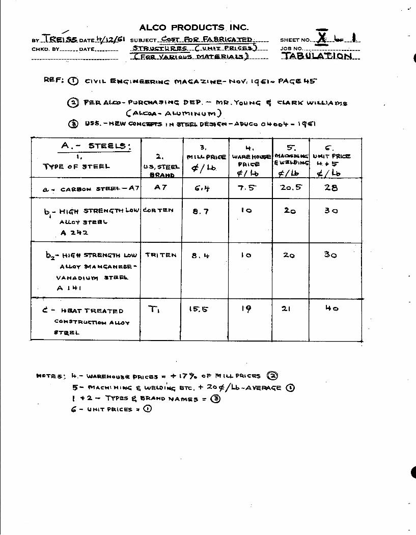
The steels investigated for possible PL-3 application included:
Designation Company
Structural carbon
Structural high strength-low alloy
A7
Cor-ten
Tri-Ten
U. S.. Steel
U.S. Steel
Heat-treated construction alloy T-1 U.S. Steel
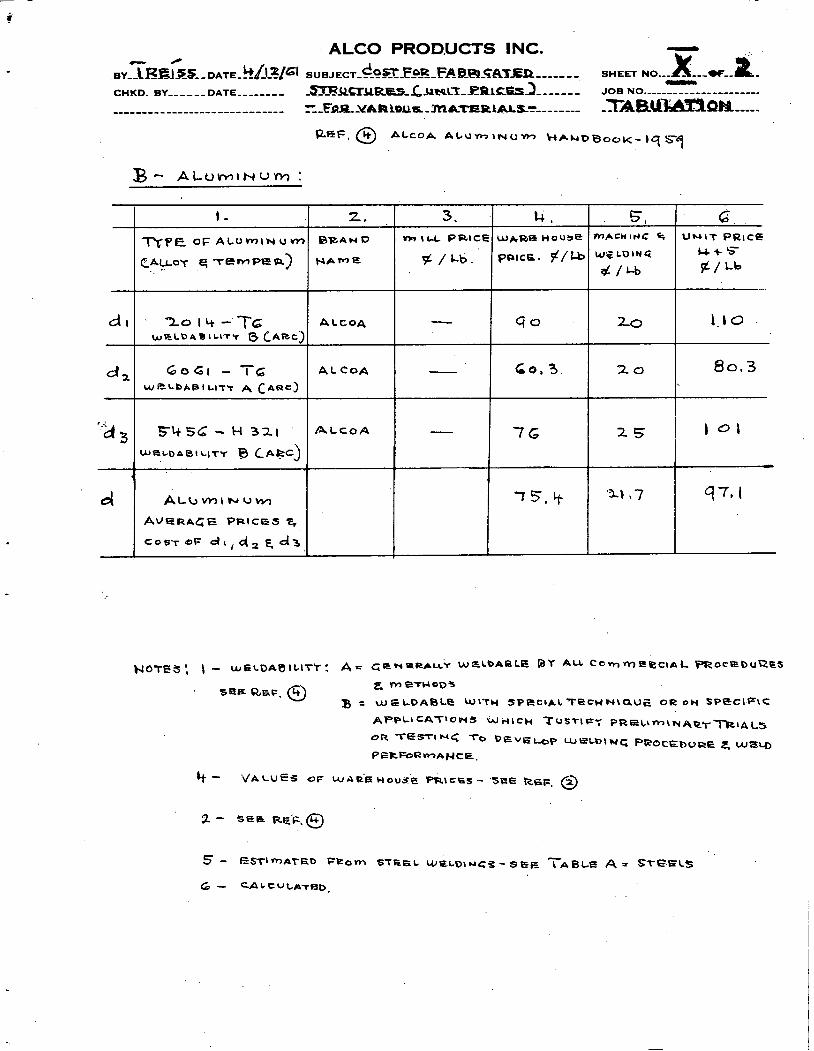
The aluminum alloys investigated for possible PL-3 application were:
Designation - Company
Alcoa Alcoa Alcoa
3.3. 2 Materials Characteristics
A cryogenic process utilizes low temperature to produce a physical change in a liquid, gas o r solid. However, as the process temperature. lowers, the problem of selecting process equipment materials for low temperature applica- tions-becomes more complex. This applies also to materials which w i l l be used for equipment, components and structures in low temperature environments.
While PL-3 will not operate in a low temperatureenvironment, i t will not be possible to install the plant modules a t once in a heated environment, and the plant will not be heated . during transportation o r storage. Thus, plant materials must be chosen that can withstand temperatures as low as - 4 0 ' ~ (dynamic) and - 9 0 ' ~ (static) without danger of brittle fracture.
Low temperatures improve some physical properties of metals. Yield, tensile and f atigure strengths all increase with decreasing temperature. How- ever, with the exceptions of iron, zinc and manganese, ductility and impact strength decrease. Many materials, including most ferrous metals, lose tough- ness and the ability to behave in a ductile manner as temperatures are lowered.
Thus, low temperatures- create -conditions favorable to the propagation of brittle fracture;.. which can resu1.t in the catastraphic: failure of complex engineering structures and equipment.
.. . . .
. . Usually, construction metals will -not fail without stretching, - sagging, bulging or . other warnings of imminent plastic failure.. However, under certain conditions, metalswhich are,ordinarily ductile may suddenly. fail a t very low s t r e s s levels .without evidence of prior plastic deformation. ' These metals fail .in a completely brittle mannelr, and this type of failure is generally manifested a t -low temperatures. To overcome the brittle failure problem, structures and equipment a r e designed to minimize s t r e s s concentrations and to utilize materials that have proven toughness based on tests and service condtions.
Toughness is the ability of a material to deform plastically under conditions of high s t r e s s concentration. This property is the prime requisite of materials specified for low temperature application. A tough material will res i s t the initiation of a crack a t points of s t r e s s concentration, and will res i s t the propoga- tion of a crack should one be initiated under abnormally high s t r e s s concentrations.
The tendency toward brittle behavior is further aggravated by notch effects (weld inclusions,' nicks, scratches, changes of sections, geometric design inter- ruptions and thelike), which localize and concentrate s t resses and res t r ic t the ability of the material to yield plastically. Ductility is also impaired to a high degree by strain induced by the effects of cold. working.
Since decreasing temperature is one of the major factors affecting toughness, the notch 'toughness: of a material is most conveniently measured by lowering the temperature of notched test specimens to a point where behavior changes from predominantly ductile to predominantly brittle. The point a t which this behavior change takes place, which varies with test conditions and cr i ter ia employed, is generally expressed in terms of a transition temperature;
Of the various tests which have been devised to measure toughness, the Charpy impact test is the most widely used fo r materials (especially steels) intended for low temperature service. In the C.harpy tests, the criterion of toughness is frequently an arbitrarily selected value of energy abso~pt ion in breaking the specimen, such a s 1 5 foot pounds a t a designated service temperature using either a V-notch o r a keyhole notch. While a foot-pound impact energy . '
value is used in specification, the investigator can also employ a selected per- centage of fracture appearance such as 50 percent shear , o r a desigqated value of lateral contraction or expansion, in a fractured specimen. In evaluating this transition from ductile to brittle behavior, i t must be understood that-no one transition temperature exists for any material except under a particular s e t of conditions and one criterion of brittleness.
The difficulty. with any of these tests lies in.attempting to apply the. results i n t e r m s of expected service behavior in full-size ~st ructures :~ Whi-le these. tests reflect the-behavior of smal l specimans; they should. not be construed as pro- viding..data .which can d-etermine the service- performance'of an actual structure, where design-, fabrications-, - residual and applied s t resses and other factors can influence -behavior. Such tests a r e considered useful, however, a s a basis for-comparing the toughness of different metals and for evaluating the effect of metallurgical variations in the same material oii .its tbughness .'.': '.... , - ' . . . . . ,
It is generally acknowledged that a s tee1 demonstrating good notch toughness ( a low transition temperature) in a Charpy impact test will probably exhibit good behavior in actual service a t o r above that temperature. That is, it will possess greater toughness than a material with a higher transition temperature. Con- sequently steels with low transition temperatures a r e preferred for services involving service s t r e s s concentration, shock loading, low temperatures o r com- binations of these conditions.
Material Selection
It is important to select materials that stand up to shocks and vibrations. Generally, a minimum Charpy value of S.5'foot-pounds (keyhole notch) is called for a t the operating temperature. Fo r severe shock loading, a value of 20 foot-pounds or above i.s repoinrnended.
Temperature Range o°F to -20°F
Some forms of carbon steel can be used up to -50°F for static conditions,, but for vibration and light shock services, the maximum limit is -20°F (dynamic conditions).
Temperature Range - 2 0 ' ~ to - 5 0 ' ~
Generally, carbon steqls become hard, brittle and prone to brittle fracture below - 2 0 O ~ , although killed'carbon steels can be used for 8 G shock service '' .
In most steelmaking processe.s, ,carbon combines with oxygen to produce gases. If the oxygen is n o t . . removed before o r during solidification, gases a r e entrapped in the ingot. When this steel is used a t temperatures below -20°F, the gas pockets can be focal points for brittle failure. A so-called killed steel has a small amount of aluminum added to scavenge the oxygen before casting. While the resulting metal is relatively homogeneous,. the temperature limit of -50°F should be raised if there is a possibility of vibration o r shock loading.
High strength, low carbon alloy steels can be used to -30°F. The so-called super high strength steels (heat treated, low carbon alloy) can be used up to -50°F in dynamic conditions, because they exhibit a minimum value of .I 5 foot-pounds'in a Charpy keyhole test at this temperature.
Temperature ,.,.-.- Range - 5 0 ' ~ to -1 5 0 ' ~
While this temperature range eliminates. all carbon steels, ferritic. alloy steels with .3 -1/2,percent nickel-content can be used: This type of steel possesses good ductility and impact.strength (-20-25 foot-pounds Charpy value a t -265OF'), making it suitable fo r static o r dynamic applications.
- . . . . . . - . . . .
Temperature Range -15b°F to. 3 2 0 ' ~ . . . . I . . . . .
1. Stainless steel (particularly Type 304)
2. Brass and copper.
.. 3. Aluminum.
4. Low carbon 9 percent. nickel steel.
Aluminum
Until the advent of high strength aluminum alloy, aluminum was used sparingly in cryogenic applications. Fo r pressure vessels, for instance, low strength aluminum is about 1/3 as strong as stainless steel and about P/3 as heavy, while costs a re the same on a weight basis.
The new, high strength aluminum alloys, used in conjunction with new welding techniques, will have a sound future in cryogenic applications, Fo r structural application in low temperatures, these high strength aluminums
-possess an unusual ability to maintain ductility and resistance to shock loading. Their tensile and yield strengths actually improve as temperatures decrease. However, a comparigon of the aluminum alloys with the high strength, low alloy steels and the super high strength, heat treated alloy steels for low temperature applicatipns up to - 5 0 ' ~ shows that the lower strength of aluminum, and the resulting increase in the amount of metal required, more than doubled the cost of a given structure.
3.3. 5 Welding.
Low temperature applications often involve complex welding problems. Dissolved gases .in welds must be minimized by ys.ing low-hydrogen, coated electrodes :. . . Submerged' materials with austenitic electodes will usually .result in a brittle fusion zone structure. Type 310 electrodes wil1,alleviate this con- dition somewhat, and weld annealing is recommended for grain 'refinement. , .
The problem of joining aluminum to other metals has received much attention. Welding techniques available: include:
. .
1. Copper-plated aluminum to stainless steel. . . 2. Tinned aluminum to stainless' steel; .
3. ' Aluminum to copper to stainless steel. .. .
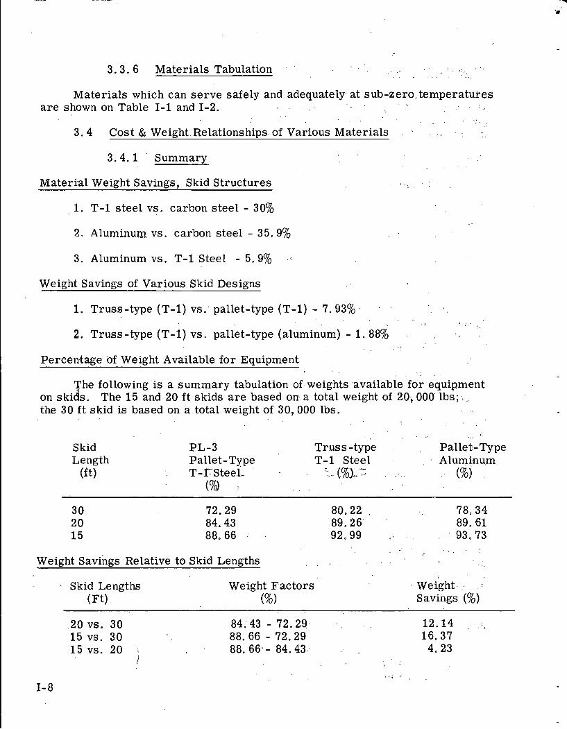
3.3.6 Materials Tabulation , '. . . . :. . . . ,. . . . . . . . - .. ,
Materials which can serve safely and adequately. a t sub-zero,. tempe,ratures a r e shown on Table 1-1 and 1-2. '4 . .~
. . . . . . ' . . -
3 .4 Cost & Weight. Relationships of Various Materials . .. . . , . , ...
3.4.1 ' Summarv
Material Weight Savings, Skid Structures . ! . , . . . .
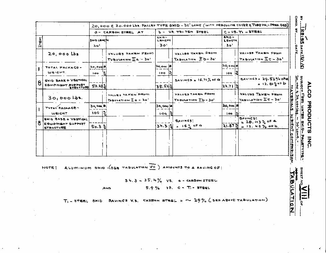
1. T-1 steel vs. carbon steel - 30%
2 , Aluminum vs. carbon steel - 35.9%
3. Aluminumvs. T-1 Steel - 5.9% .-.
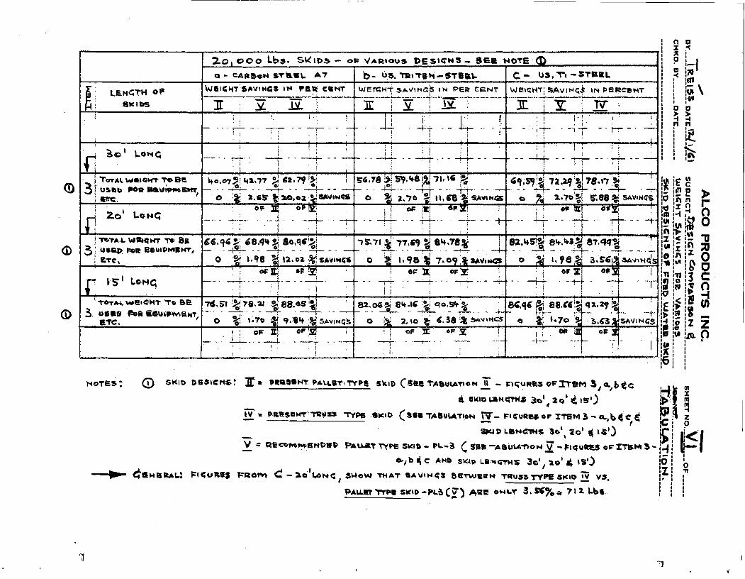
Weiaht Savings of Various Skid Desians
1. Truss-type (T-1) vs: pallet-type (T-1) - 7.,93% . . . . . . .. . . . . I . . . ,
2. Truss-type (T-1) vs. pallet-type (.aluminum) - 1. 88% . . .
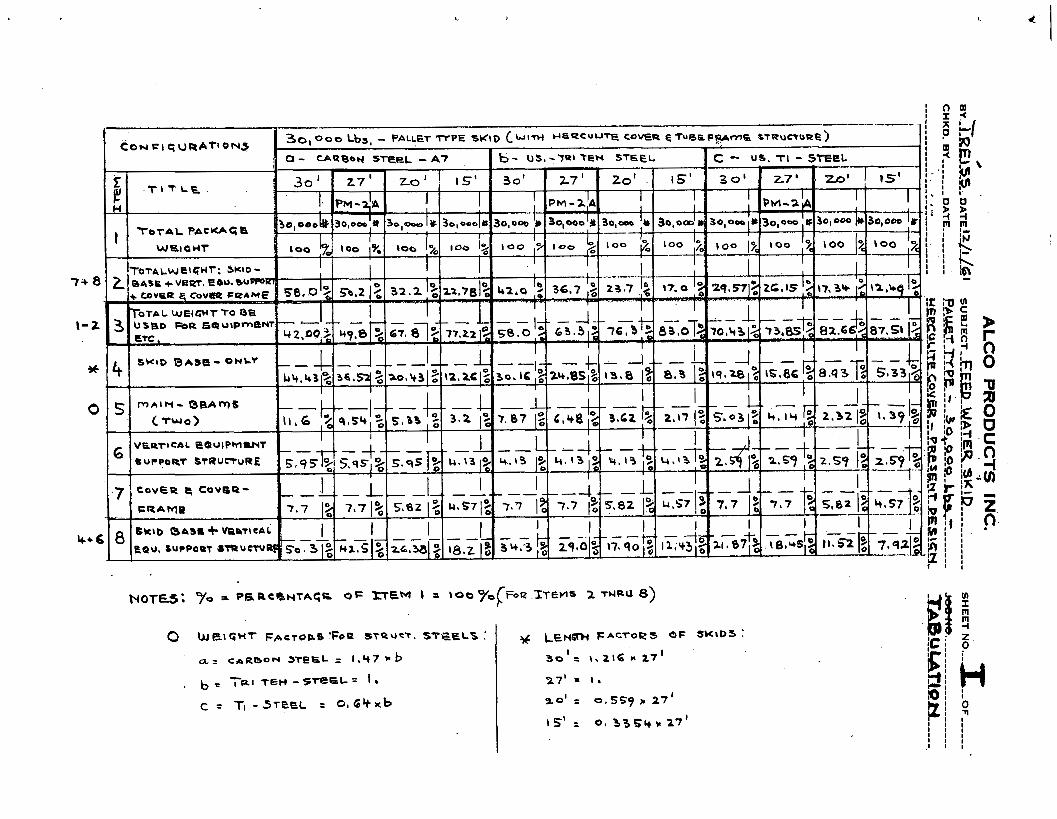
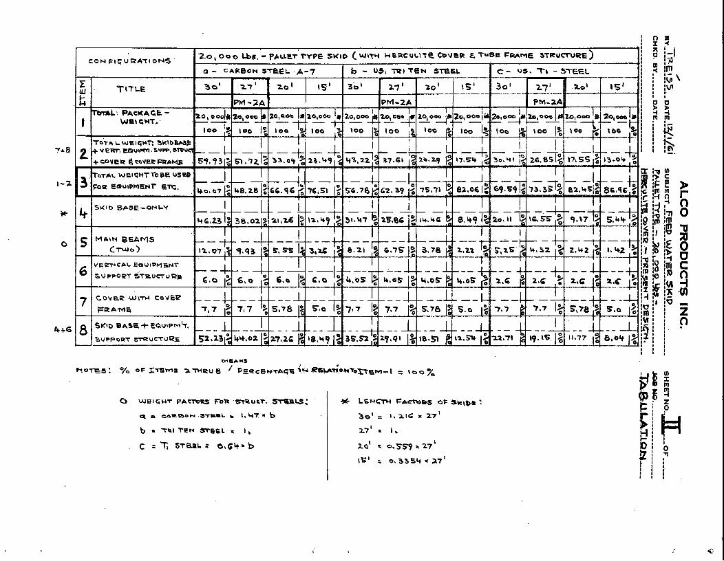
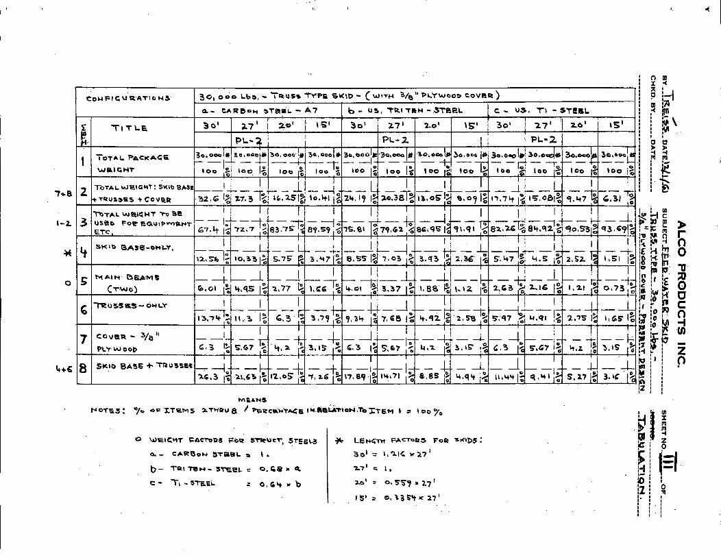
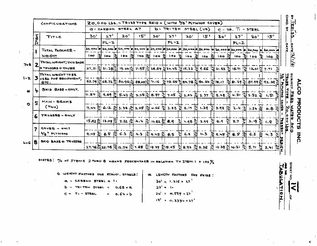
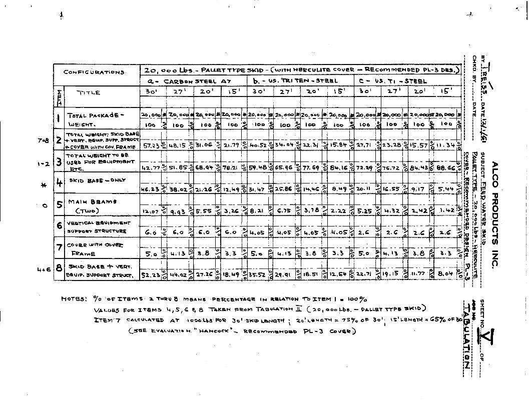
Percentage of Weight Available for Equipment . .
The following is a summary tabulation of. weights .available for equipment on skids. The 15 and 20 ft skids a r e based on: a total weight of 20,000 lbs;.: .: the 30 f t skid is based on a total weight of 30,000 lbs. . ,
. .. ., . Skid PL-3 Truss -type Pallet- Type Length Pallet-Type T-1 Steel ' . . . A1umi.nu.m
(it) - . T-.rsteel- : . . . . . . . . . (%i (%) : . .
. . . %
Weight savings Relative to Skid Lengths . . . . . . ..
, Skid Lengths Weight Factors Weight. .. .
(Ft) (%I Savings (%)
.20 VS. 30 84.43 - 72.29. 12.14 . :.,
15 VS. 30 88.66 - 72.29 16.37 15 VS. 20 88. 66.- 84.43..- 4.23
,i . .
. . : . . . I- 8
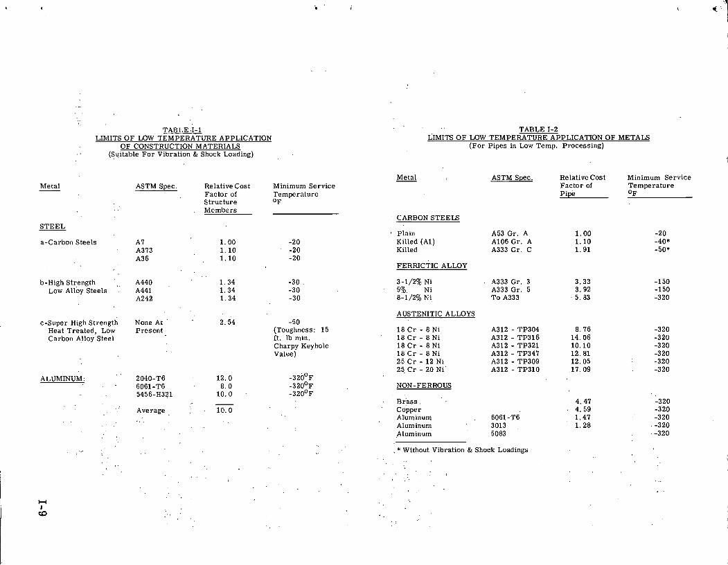
TABLE 1-1 LIMITS O F LOW 'TEMPERATURE APPLICATION
O F CONSTRUCTION MATERIALS (Suitable F o r Vibration & Shock Loading)
Metal ASTM Spec. Relative Cost Minimum Serv ice - Factor of Tempera ture S t ruc ture "F M e m b e r s
S T E E L
a-Carbon S tee ls A7 1 . 0 0 -20 A373 1 . 1 0 -20 A36 1 . 1 0 -20
. . A440 b-High Strength ,, 1 . 3 4 -30 .
Low Alloy Steels . A441 1 . 3 4 -30 A242 1 . 3 4 -30
c-Super High Strength None At ' 2:54 -50 Heat Trea ted , Low P r e s e n t (Toughness: 1 5 Carbon Alloy S tee l i t . lb min.
Charpy Keyhole Value)
ALUMINUM:
- . ' Average 10 .0
TABLE 1-2 LIMITS O F LOW TEMPERATURE APPLICATION O F METALS
( F o r P ipes in Low Temp. Processing)
Metal ASTM Spec. Relative Cos t hlinimum Serv ice F a c t o r of Tempera ture P ipe O F
CARBON STEELS
o Plain Killed (Al) Killed
FERRICTIC ALLOY
3-1/2% Ni 5 . Ni 8-1/2% Ni,
A USTENITIC ALLOYS
NON-FERROUS
A53 Gr . A A106 Gr . A A333 G r . C
A333 Gr. 3 A333 G r . 5 T o A333
B r a s s . ' ' Copper
Aruminurn . 6061-T6 Aluminum 3013 Aluminum 5083
. * Without Vibration & Shock Loadings
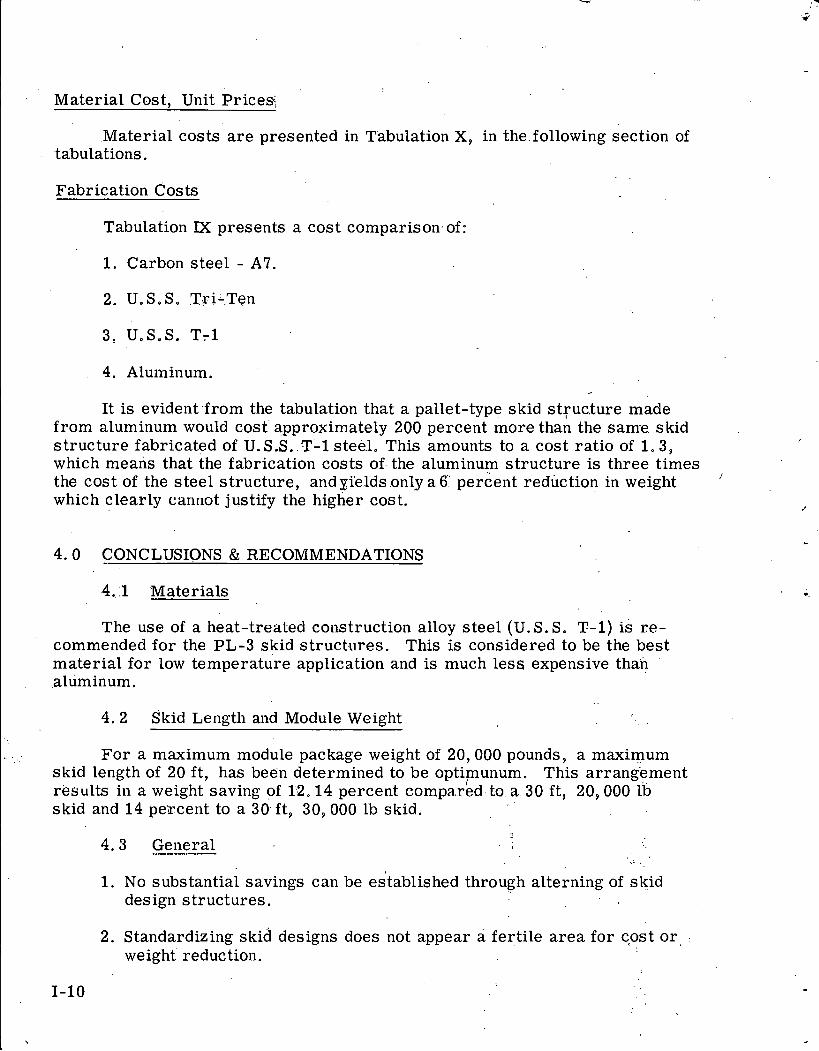
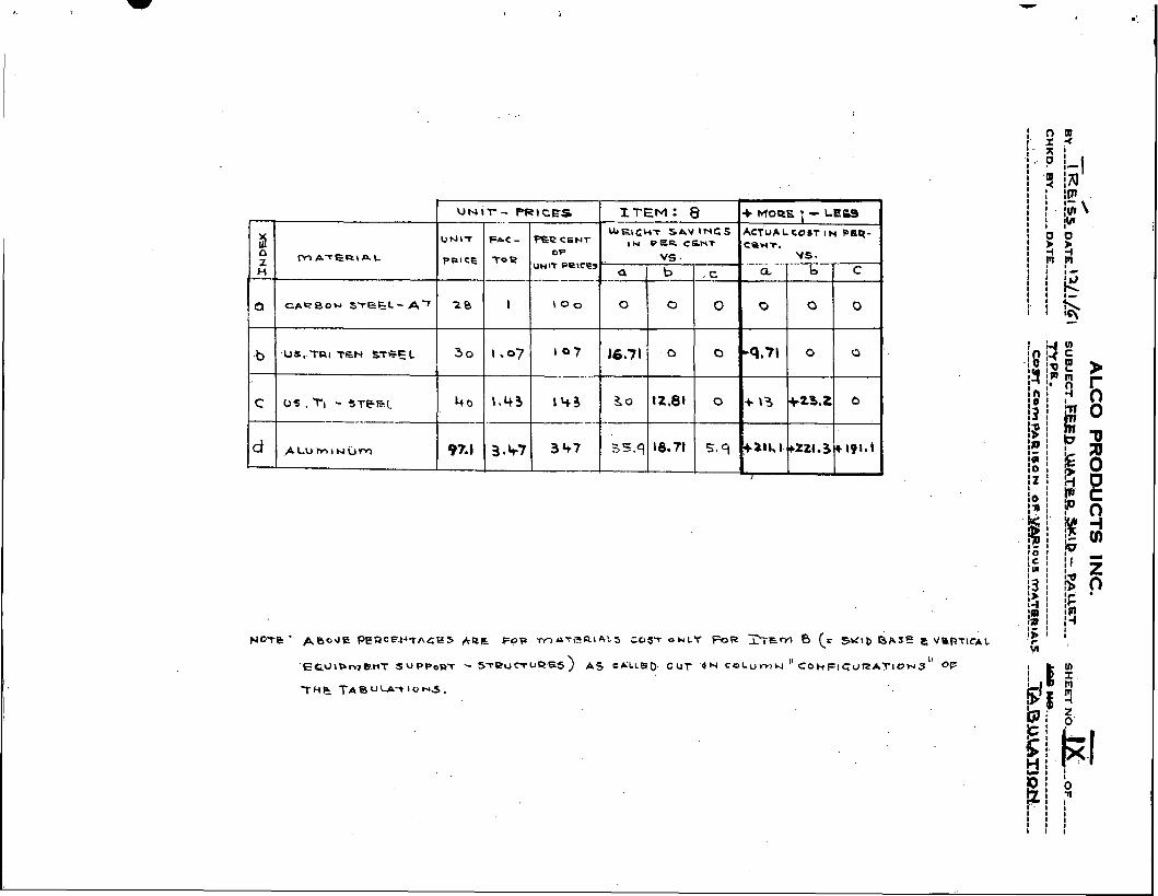
Material Cost. Unit Priceg%
Material costs a r e presented in Tabulation X, in the.following section of tabulations.
Fabrication Costs
Tabulation M presents a cost comparison~of:
1. Carbon steel - A7.
2. U,S. So T?i-.Ten
4. Aluminum.
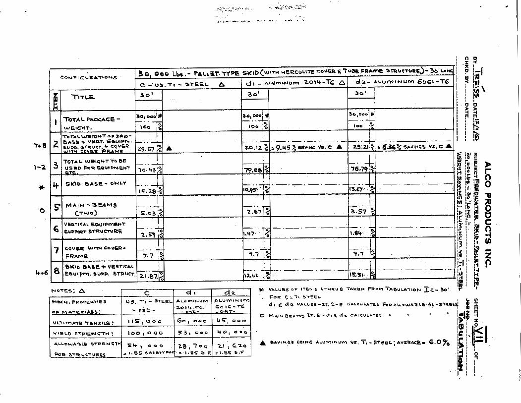
It is evident from the tabulation that a pallet-type skid struc.ture made from aluminum would cost approximately 200 percent more than the same skid structure fabricated of U. S.S.. T-1 ste&l. This amounts to a cost ratio of 1.3, which means that the fabrication costs of- the aluminum structure is three times the cost of the steel structure, and yields only a 6 pe,rcent reduction in weight /
which clearly canriot justify the higher cost.
4.0 CONCLUSIONS & RECOMMENDATIONS
4.. 1 'Materials ..
The use of a heat-treated col~struction alloy steel (U.S.S. T-1) is re- commended for the PL-3 skid structures. This is considered to be the best material for low temperature application and is much lesq expensive than aluminum.
4.2 Skid Length and Module Weight . .
For a maximum module package weight of 20,000 pounds, a maximum skid length of 20 ft, has been determined to be optimunum. This arrangement results in a weight saving of 1:,22. 14 percent compared. to. a. 30 ft, 20,000 ib skid and 14 pe'rcent to a 30. ft, 30,000 lb skid.
4.3 General ---- I
1. No substantial savings can be established through alterning of skid design structures.
2. Standardizing skid designs does not appear a fer,tile a rea for cost o r , : weight reduction.
1-10
3 , A weight reduction of sk ids can be affected only by using high ,:;. s t r eng th steels or light weight ma te r i a l s (.aluminum).
4. A f u r t h e r c o s t and weight sav ing can be affected by consolidating equip- men t functions and eliminating skids .
. . . . . . .
5 . 0 WORK IN PROGRESS .%." -
1. Design r u l e s f o r skid b a s e s .
. I 2. Handling r u l e s . . . . , .
. . . . 3. Study of tiedown devices and r u l e s for placement . . , , . ." .
. .
Work in p r o g r e s s is about 50 percgnt cornp1,ete and wili be .completed . .
as ' a p a r t of the f inal plant design activit ies. . .
------
I 30, ooo Lbs, - PALLET ITPE S K ~ D C b ~ n t H E = C u U t E COVER E Tussppnma trnumuas) Cow PI ~ U R A T ' O N S I C - U S . T I -STEEL
0 bJEl F A C T O ~ ~ !FOR S'?PUcT. STEELS : a= ~ ~ R B O N 3TEEiL = 1.47 * b -
, b 8 PI TEH - S-Pb ': 1 .
c = T, -STEEL : o16rtxb
0 w e ~ c u r ~ ~ o m a f FOR .5poue~. s%n&s: * LEN- FA-- OF s)(\@. :
E CAPBON .STCIL r 11-47. * b 3-' = 1 . ;LIG x 27'
b r TPl T B N S l h S L E I , 17' . 1.
. c = T S T U L : 8 , G l t h b SO' a 0 . 5 ~ ~ h 2 7 '
is1 = o, 3354 r 27'
I
C ~ U F I C U ' U A T I O US 30 ' ooo L ~ B . - TRUSS TYPE SY\D - ( WITH 3/8" PLYWOOD covert) I - .
Q - CARBON ~ T ~ P L - A 7 ( b - US, TRI TBH - STBEL I c - us. TI - sreaL I
I
T I T L E 39' 27' i 20' 1. \.St 30' 27' 20' \S1 i 30' 27' '
26' ' i - PL-2 PL- 2
I
I ' TOTAL PACKAGE - -i--- WRIGHT -
I I 2 T O T I L W E ~ G * T : S ~ ~ ~ B U E
+ r Q U S 3 6 S + COVeR 1 I
~ T A L W@\tHT TO --- E T C ,
-
I I I I i I j I 1 - IO. 1 I
5 MAIN. BEAMS - + i - 1 - 1 , - -d-- -+-- I - - I - I In 0 j:
CT.WO) 6.01 ,; b . 9 ~ 1; 2.77 4 1.C~s~a13/ 3\37 i 2 - ~ . ~ ~ ,.ll k-2!'3 ,f: 2.16 12 1 . ~ 1 2 - 0 . 7 $
n u s s e ; ~ - d w c * 6 --
7 C O V E R - 3/e''
PLYWOOD I
I
8 S K I 0 BASE -b TRDSSBI, 4 - - 26.3 ,t 1
T~TALWIIGHT:' SKID base
EX ,
PL -2 P L - z c PL- 2 lolQ-b or !C 26, oao.!! 2o, o=aJ 20. almOk !,, a1-.4 zqow L -- - - - - - - -- -- -- -- - -
\ O O 5 a 16 100 1% , l o g 1% I00 '2 \oo 8.;
I I I I I I
1M : V A L U E S OF l r e l r ~ s r-rusu a TAKBN Faam TPBULPITION SC- sol r
. F o e c r TI STEEL
dm d l vburs-xr . 1 - s c r L c u u m . F.. buewrare:lr - S V R ~ ~ { , t 0 M * I N R ~ & ~ ~ m. 5 - d l f. d a C A ~ . C U L & ? ~ ~ 11
I , t I
.---- -- - --- .- ' 20, ooo 6 3 o l 0 0 0 L ~ ~ . . P A L L ~ T - T Y P E . ~ . W O - ~ ~ ' , L O N G ( W I T ~ HERCULITC COVE~?:~.DBEFR.-%.DES:
a - C ~ P B O W S T E ~ L ~7 . . b - US. TRI TEN s t e e ~ C - US. TI - STB-EL ---..- - .... -... I 6k10- 'bklb -
L I N G T Y LENGTY
30' 1 . S O 1 30'
2.0, 0 0 0 Lbs I 1 V ~ L U R J T A U O W F E o W vALl1e6 T A Y P h F P O m
--,-. - . f T U B U C A ~ I O N I&.- . - . 301 . . TABULATIOH . . xb- 301 . d TLBULATION xc - 30' .-
I TOTAL P A C K A G E - 20 ,00 *$ ~ , O O O # 20,000 i t ----- -1 ---- - - - - - - w e ~ c w r . loo % I00 %
- 2 . . . . . . - . -
~ r i b B P S E L ~ ~ t a w = ~ ~ ----- , S A V I N G ~ ~ l6,71;3baFQ - - - - - S A v \ H G S a 2 9 , 5 2 ° / o ~ k 12, 8 1 % 0 ~ b
22.71 2 : I
1 ,v*.LU=S T A K E N ' F ~ O ~ vIt.ue3 T A K R ~ FROM . VALUES Tnlcsrr R R O ~
3 0 ~ 0 0 0 Cba. . j T A ~ U L A T ~ O W I a - 30 I r r s u r r t o w T b - 3;' . . I ' ~ a ~ u u - r b o w X C - 30 ' - -
30, ooc IY ao,o=la - ---- ..- .---, -. 1 ----- roe % WCIGHT 100 3 ; . .. . -
6 K \ b r B A S ' E + y a ~ r i ~ , , . 1 : I I SAVINGS:
S h v r w G s : 8' ~ ~ u t b w a n r sup~cq.r ----7-- '-. = 28. b 3 Oc, O F a .-A .,- -. * -!
BTR UcTu- 50,s .% 3h.3 % = 16:: o F 0 ,%IW% = 1 2 , ~ ( 3 % a ~ b . ,
I
I !
I I i ., . -
w o y ~ : c q ~ , , ~ , ~ , ~ ~ s w l 0 -(SCR r a D u L h r \ o w 2.) A m o U Y T S t.0 A SAIJ.lYG O F :
u ~ i r - PRICES r
ITEM : 8 + MoR.61 ; - LE69 3
~ 6 l G H T S P V I N G S ACTUALCOST IN p ~ q - * -PC=Nr IN P 6 B - c S r i ~ c e H ~ .
M A t E R \ A C O F VS . . .- . . . . . . .... vs. PwcE pelce,
H --. . a .- -.-. - .---- b .c a ---.-6 c '
0 C A R B O W S T E K L - A ~ 2 8 1 \ o o 0 0 0 0 0 0
.b .us,.rn~ TGN STBE L 3 0 1-07 167 16,7l . o 0 7 0 0
c U S , TI - 3TFEl h o 1 - 4 3 1 4 3 3 0 tt.81 0 + \ 3 +23.2 b --..-- .- ..
d . A L u ~ ~ N . u M 97.1 7 3 47 35.9 16.71 5. q F Z t L b.'+Z~1.3+191~1
I A
M ALCO PRODUCTS, INC. 0 /
~~.-TR~ISS- DATE.~?$W-CI su BJ ECT--&~--%E-FA,BRCGAEI~~ ----- SHEET ~b..-X'--ib~ ---k- - CHKD.BY ------_ DATE .-------- .-~R-u~-sL~---c-K~~x-P_&L~w;+~ ---- JOBNO ..--------------- ----
ALCO PROD,UCTS INC. - w @
~Y--LREJs_L, DATE-!?L~-P[~I SUBJ E C T - & ? ~ P - O ! - F A ~ P ~ - C A T ~ ----- - -, SHEET NO.-- - CHKD. BY ------ DATE -------, -~YCTURW-LY'PPLZ-LRLC~~ - - - - JOB N O .---------,,-,-,-,,-,. ---,------------------------- ~ ~ - € . . X A ~ ~ L Q U S ~ - ~ & T B E ~ ~ L U S ~ -------- - y A a w Q M ,,,,-
(t - V A L U E S OF w H O U S ~ FVUCPS - SEE RGF. @
5, mAcHlrJC 4
W G L O L n G
o ! / *
10
3-0
dl
d z
Qa <
d
G UWIT P R l c e
u + s $ / Lb
1 1 0
8 0 , 3
2.
@-AH D
w.rpme
ALCOA
A L C O A
A L c o A
I - R P E OF ALuvnrN u rn
~ A L L O ~ ~;-rernpes~]
2014-TG u ~ E L D a 8 1 ~ t t . r CARC]
- 6 0 6 1 - 1 6
W E C B A B ~ L I T ~ A CAR^)
S b S 6 - H 321
~ ~ ~ n a t c l r v B C A ~ C )
A ~ t , v n \ ) . r u v ~
AVERAGE PRICES E,
COST aF d t , d 2 6 d3
3. rrr ~ L L PRICE
$ / L b .
- -
- I
k , WAFLE H O U ~ ~
Q P I C C . $/Lb
ci 0
G o , 3
7 G
7 5 , 't-
2 5
ex\ ,-7
) 0 1
q7.1

-
-
- -7
WA
STE
HE
AT
ION
SYS

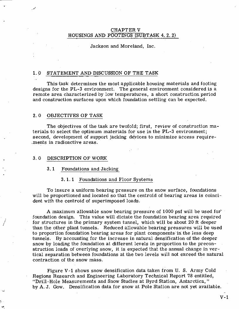
CHAPTER V HOUSINGS AND FOOTINGS (SUBTASK 4.2.2)
Jackson and Moreland, Inc.
1.0 STATEMENT AND DISCUSSION OF THE TASK . ,
This tas'k determines the most applicable housing materials and footing designs for the PL-3 environment. The general environment considered is a remote a r ea characterized by low temperatures, a short construction period and construction surfaces upon which foundation settling can be expected.
2 .0 OBJECTIVES OF TASK
The objectives of the task a r e twofold; first, review of construction ma- ter ia ls to select the optimum materials for use in the PL-3 environment; second, development of support jacking d6;vices to minimize access require-
..merits in radioactive areas.
3 . 0 DESCRIPTION OF WORK
3 .1 Foundations and Jacking
3 .1 .1 Foundations and Floor Svstems
To insure a uniform bearing pressure on .the snow surface, foundati.ons will be proportioned and located s o that the centroid of bearing a reas is coinci- dent with the centroid of superimposed loads.
A maximum allowable snow bearing pressure of 1000 psf will be used for' foundation design. This value will dictate the foundation bearing a rea required for structures in the primary system tunnel, which will be about 20 f t deeper than the other plant tunnels. Reduced allowable bearing pressures will be used to proportion foundation bearing a reas for plant components.:in. the less deep tunnels, By accounting for the increase in natural densification of the deeper snow by loading the foundation a t different levels in proportion to the precon- struction loads of-'overlying snow, it is expected that the annual change in ver- tical separation between foundations at the two levels will not exceed the natural contraction of the snow mass.
Figure V-1 shows snow densification data taken from U. S. Army Cold Regions Research and Engineering Laboratory Technical Report 78 entitled, "Drill-Hole Measurements and Snow Studies at Byrd Station, Antarctica, " by A. J. Gow. Densification data for snow at Pole Station a r e not yet available.
With the passage of time, it is probable that the floor of the tunnel c ross section will change from a level to a crowned surface in which the outer edges will be depressed from their original elevation relative to the building floor, and the centerline will be raised. Where practicable, foundations will be lo- cated near the quarter points of the tunnel width where the change in relative elevation is minimal.
T o allow f ree circulation of tunnel air under the buildings o r other po- tential heat sources and in accordance with contract requirements, flbor sys- tems will be--elevated to maintain a minimum clearance of 2 ft-6 in. between the tunnel floor snow surface and the lowest point on buildings or drain pipes. Foundations and jacking equipment will utilize this under floor space.
Where metal beams o r t russes a r e used t o elevate the buildings and distribute loads t o the foundation bearing surface, wood, o r other insulating material, bearingiblocks and sills will be used as required to break any di- rect path which might conduct heat to the snow bearing surface. . .
Wood-framed, stressed-skin plywood panels will be used t o form. the foundation bearing surfaces. In addition to ease of erection and the advantage of providing a bearing surface with desirable heat transfer properties, the comparison of shipping weights and volumes of spread footing members shown in Fig. V-2 indicates a weight saving in favor of stressed-skin panels over cellular steel panels o r wood planking. The bottom 'of panels will be located a t least 6 in. below the tunnel floor snow surface s o as to bear on snow un- disturbed by construction traffic, and to provide further insurance against heat transmission to the snow bearing surface.
Wood, aluminum and steel a 1 have a place in an economical design of the foundations and buildings. The modulus of elasticity and the tensile strength of each of these materials increases at low temperatures. Many steels, how- ever, exhibit a tendency to brittle behavior as the temperature is decreased. The following tabulation lists some readily available materials which a r e &it- . able for structural purposes in cold climates. Minimum Charpy V-notch . longi- tudinal impact test values and test temperatures a r e listed for the steels. Those steels which can absorb not less than 15-ft lb of energy when subjected to a longitudinal Charpy V-notch impact tes t a t a temperature of - 9 0 ° ~ o r colder a r e considered acceptable for use in snow tunnels at Byrd Station.
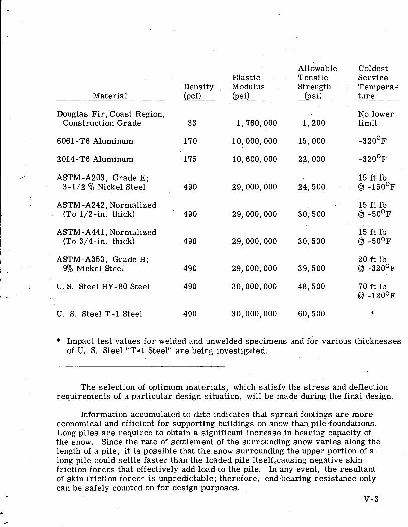
Material
Douglas Fir, Coast Region, Construction Grade
6061 -T6 Aluminum
2014-T6 Aluminum
,.., ASTM-A203, Grade E; 3-1/2 % Nickel Steel
ASTM-A242, Normalized .. (To.l/2-in. thick)
Elastic Density , Modulus Tpcf) (psi)
Allowable Tensile Strength ' ..
(psi)
Coldest Service Tempera- ture.
No lower limit
ASTM-A441, Normalized 15 ft lb (To 3/4-in. thick) 4 90 29,000,000 30,500 @ -50°F
ASTM-A353, Grade B; 20 f t Ib . . 9% Nickel Steel 490 29,000,000 39,500 @ - 3 2 0 ' ~
1 U. S. Steel HY-80 Steel 490 30,000,000 48,500 70 ft lb I/ L- @I -120°F I
U. S. Steel T-1 Steel 490 30,000,000 60,500 *
* Impact test values for welded and unwelded specimens and for various thicknesses of U. S. Steel "T--1 Steel" a r e being investigated.
The selection of optimum materials, which satisfy the s t r e s s and deflection requirements of a particular design situation, will be made during the final design.
Information accumulated to date indicates that 'spread footings a r e more economical and efficient for supporting buildings on snow than. pile foundations. Long piles a r e required to obtain a significant: increase in bearing capacity of the snow. Since the r,ate of settlement of the surrounding snow varies along the length of a pile, it is possible that the. snow surrounding the upper portion of a long pile could settle faster than the loaded pile itself,causing negative skin friction .forces that effectively add load to the pile. In any event, the resultant of skin friction force:. i s unpredictable; therefore,. end -bearing resistance only can be safely counted on for design purposes.
v - 3
The reactor building will be suspended at all times f rom. jacks located under the buildihg;; To facilitate the remote control of .jacking and level measurement required, only 4 jacks will be.used. The building .dimensions a r e consistent with the use of i ts framing as a stiff box t russ to deliver the building and primary equipment loads t o the foundations. By taking advantage of the stiffness of the building superstructure, the height of the building floor from the tunnel floor will be less than would be required otherwise. - A lined pit, stiffened to res i s t the side pressure of the snow and sur.charge loads, will be provided at each .
jack screw rod. Pyramidal cribs o r t russes will be used to deliver the jack loads to the snow bearing panels.
The secondary and service buildings will be of light construction, and will ordinarily be supported directly by their foundations. Jacking stations along thedzngth of the b u i h n g s will be used as required for local leveling, o r to ra i se the entire building, until shims or cribbing members a r e inserted to bear the load. To avoid buckl'ing.of the building walls o r other damage from the settlement of foundations, a continuous .fauss of triangular cross section will be provided along each side of the building t o deliver loads to the snow bearing panels. Floor framing members will cantilever beyond the top chord of the t russ on each side.
3 .1 .2 Level Measurement
Means of detecting changes in level due to settlement of the snow founda- tion a r e required. There a r e two problems: One, t o detect the small settle- ments of the buildings themselves and, two, to detect uneven settlement of in- dividual foundations under the primary building which might afiect the opera- tion of the jacks.
For detecting changes in. building level, no system offers greater relia- bility o r simplicity than a liquid-filled manometer, provided that a satisfactory fluid suitable for the operating temperature range can be found.
Other systems were bonsidered, but all suffer either from complexity o r from inability to establish a suitable reference level. Lacking such a reference, any mechanical system would have to depend on angular displace- ment, such as measuring the angle between a building member and a reference pendulum. Due to the lengths of the buildings involved, such angles a r e too small to measure accurately, Another possible system consists of a collimated light source on a gimbal-mounted platform, aimed at distant: photocells. This would be complex, and it would be difficult to collimate a light beam well enough to provide sufficient accuracy. Also, neither of these methods is suitable to measure the relative movement between the primary and secondary buildings, since the presence of the snow wall precludes either a line of sight o r a rigid mechanical connection between the buildings.
In a search for manometer fluids, pentane, which is used in thermometers for very low temperatures, and the silicones were investigated first. The best
available silicone, Dow Corning 330 Fluid, while pourable below - l O o O ~ , has too high a viscosity to be suitable as a measuring fluid. Pentane has excellent vis- cosity characteristics, but it is highly inflammable and has a flash point of ap- proximately -400F, making i t hazardous to handle.
A survey of some 9000 organic compounds listed in the Handbook of Chemistry and Physics resulted in the selection of ten which had suitable melt- ing and boiling points. Methanol is one of these, and would be usable. It is inflammable, but not too dangerous. Most of the others a r e not readily avail- able. One of the most promising is tetraethyl tin, b ~ t the total commercial production to datei's 400 grams (less'than one pint) and this is for sa le at $100, a prohibitive price. However, this mi.ght be reduced i f a larger quantity were to be made, and this material is still a possibility.
Humble Oil Company has stated that either kerosene o r Varsol, a petroleum- based solvent, would remain mobile at these temperatures,. but would contain some particles of waxy materials. Both arevolatile but, like methanol, not too hazardous. Another fluid which Humble suggests is a commercially available product known as C8-Oxi-Pelargonate.
The most promising fluid s o far is a fluorochemical liquid produced by Minnesota Mining and Manufacturing Company and designated F6-75. It is inert, stable, non-toxic, and has a pour point as low as -150'~. Its viscosity at - 8 0 ' ~ is 6. 5 centistokes. This is the lowest temperature for which viscosity data is available, and the viscos'ity at lower temperatures must be checked. However, this value indicates that i t s viscosity should be satisfactory, In gamma radiation tests , this material experienced a 22 percent increase in viscosity after 1 x 10⁸ roentgens, indicating very adequate radiation resistance for this application.
To minimize temperature effects, the system should be entirely outside the buildings. For the system piping, ei.ther aluminum or copper would be suitable, and.the system could be standard pipe or thin walled tubing. The choice depends primarily on the possibility of accidental damage and can be .made only when the final layout is more definite.
For the secondary buildings, direct visual reading is planned, using flat glass, reflex-type gages for safety and to increase readability.
For the primary building, remote reading is necessary. Buoyancy dis- placer level indicators and magnetic types having moving parts and a r e unde- sirable where they a r e inaccessible for maintenance. The magnetic types would be difficult to arrange for remote, continuous indication. Liquid con- duction probes and ultrasonic probes a r e limited to on-off type readings. The capacitance-type level indicator, made by Robertshaw-Fulton, and others, will provide remote, continuous indication and appears most suitable for this service. Although some of the fluids being considered, pentane, for instance, have very low dielectric constants, Robertshaw assures us that': the instrument can operate with. these values.
v - 5
This instrument, as presently manufactured, has a bridge detector and oscillator circuit which would have to be located in the inaccessible area.- This unit contains an electron tube and its reliability for this service is questionable. However, a revised model is being developed using solid state components which should be satisfactory. We a r e presently investigating the guaranteed attention- f ree operating life of this unit. The remaining cornPonerds of this instrument can be remotely located s o that accessibility is no problem.
- A single remote indicator, with a selector switch to select the point being
read and simultaneously light an indicating light on a panel diagram showing the point, is presently planned. This is considered to be the simplest system to read and miiriimiz:eS'the-c haqce-oT e r r o r in reading. The system would have five reading points; one at each corner of the reactor building and one, for reference, at a . point on one of the secondary buildings.
As an operating convenience and to avoid spillage when filling the system, use of a supply tank and one or more pumps is being considered s o that fluid could be added to, o r removed from,'?€hesystem without handling. By using a small displacement.pump, such as a metering type plunger pump, this would allow precise adjustment of the fluid to a reference level before readings.
Should radiation damage t o the fluid be a matter of concern, this system would also allow the primary building system to be kept empty, and to be filled only when a reading was to be taken.
For detecting uneven settlement of individual primary building foundations, only the angle must be determined. The jack system is planned to tolerate up to 5 degrees misalignment. Theref ore, a pendulum type instrument is practical. It is planned only to indicate whether the 5 degree limit has been reached. '
Since the available standard instruments of this type a r e apparently all designed for use in servosystems in. moving vehicles and therefore incorporate costly features not necessary for this application, we have designed a pendulum type instrument which will close a contact when the 5-degree l ~ m i ~ h a s been reached in any direction. The contact would light an indicating light, probably through a sensitive relay, in order to reduce the current through the contacts.
3. 1 . 3 Jacking
For the secondary buildings where the foundations a r e accessible, a system using ordinary building jacks and foundation shims is adequate and nothing more complicated is justified.
For the remote jacking of the primary building, the jacking mechanism must be simple, reliable, and self locking. These requirements eliminate hydraulic o r air - jacking systems, because they depend on maintaining f)uid pressure to support the load. The Texas Tower jacking system was investigated but it also depends on maintaining fluid pressure.
The above requirements a r e met by screw jacks. One possibility is the bench stand used for operation of sluice gates, built by Rodney Hunt Machine Company, and others. These a r e available as catalog items up to 60-ton capacity, and as semi-custom designs in larger capacities. They a r e suitable for power operation with various types of motors; for example, we customarily install them to be driven by portable air motors. However, for remote electric opera- tion, it would be necessary to provide additional gear reduction in the motor to obtain a suitable operating speed and to provide limit switches to prevent overtravel. For these reasons, Rodney Hunt Company feels that a valve opera- to r specifically designed for motor operation would be more suitable than the bench stand.
Electric motor operation appears most desirable. Mechanical linkage would obviously be most reliable,but .is impractical due to the plant layout. .
Air motors a r e subject to freezing of the air lines, making them unreliable in this service. Hydraulic motors would be practi tal if a suitable hydraulic ,
fluid can be found. Several manufacturers have been asked for opinions on this, but have not replied as yet. However, a hydraulic system would. be. ex- . .
.: pensive and it is doubtful that it would be any more reliable than electric..m.~tors. . .
For electric motor operation, a suitable unit is the Limitorque SMA-4X valve operator, manufactured by Philadelphia Gear Works, which will provide 200,000 lbs thrust with a travel ra te of 1/4-in per minute. These units a r e designed to operate large gate valves having a threaded stem which. is raised o r lowered by operation of a nut within the operator. For this application, the operator would be mounted on the foundation and the valve stem would be r e - placed by a jack screw which would support the building.
These operators a r e supplied with geared limit switches which can.be se t to limit the total travel, and torque switches which can be used a s a back-up protection to cut the power if the jack is overloaded. These operators can be .supplied with Beacon 325 lubricant, which is recommended. for service at -65OE' and has performed satisfactorily at - 1 0 0 ° ~ , and Dow Corning 33 silicone grease, with a usable range to - l O O ° F o r below, is also being investigated.
With a five-foot range on the jack, we prefer to hang the building load from the jack. This places the screw in tension and avoids subjecting it to column action.
Because of the possibility of uneven settlement, it i s necessary to pro- vide flexibility s o that tilting of the support will not bend the jack screw. Various means of accomplishing this have been considered, including cable snubbers to transfer load t o the high side of the foundation, and a system using a drum hoist and cable support in place of the screw jack. While both a r e feasible, the first suffers from complexity and the second from instability.
. . . .
, .
The solution which is, at present, most attractive is to mount the jack on a spherical Lubrite bearing with a system of guides, also with Lubrite bearings t o hold the jack in adjustment.
Lubrite, a product of Merriman Brothers Company of Boston, is extensively used in bridge construction for machinery bases an,, for other high-pressure bear- ing applications. It consists of a bronze bearing surface containing holes into which lubricant is forced at high pressure. While performance tests a t - 1 1 0 ° ~ have not been conducted, it is in use successfully in Alaska, and its charac- terist ics a r e such that low temperature operation is expected to offer no difficulty.
It is proposed to operate the motors by momentary pushbuttons, which must be held continuously while operating. A single se t of pushbuttons would be used, with a selector switch to connect the buttons to any one jack and, a t the same time, indicate on the panel diagram which jack was operable. This would compel the operator to make a jack selection before operating and lessen the chance of operat- ing the wrong jack. These, together with the slow operating speed of 1/4-in. per minute, should avoid misoperation. As an additional safeguard, the system could be interlocked. Probably the best way to accomplish this would be with a "super- visor's key" on the selector switch, thus insuring that a qualified person is always aware of operation.
3. 2 Building. Su~e r s t ruc tu re -
3 .2 .1 Purpose and Scope
This study was made to develop concepts and evaluations which will, in fhal design, aid to producing building superstructures best suited to house the com-' ponents of Nuclear Power Plant PL-3 as installed in snow tunnels a t Byrd Station on the continent of Antarctica.
Three major tasks were pekformed in arriving at concepts to be incorporated in the final superstructure design.
1. Data Collection
A survey was made of all sources of information which were known o r thought.to be of value. The objective was to benefit from the experiences of others in this type of work; to obtain cost, performance, and avail- ability data on various possible construction materials, and to solicit new ideas which might be used. A secondary objective was to develop a l is t of f i rms that might desire [t'o bid on the final design.
2. Data Evaluation
Conditions to be satisfied by the building superstructures were studied and, in the light of data collected, a basis for final design was estab- lished.
3. Analysis of Building Components ,
All components of the superstructures were studied and compared. Definite recommendations were made, where possible, and later evaluations were indicatedior components where the selection will depend on final design details o r on bid prices.
3. 2. 2 Data Collection
Three methods of attacking the data collection phase of the work were used: research, personal contact and solicitation by mail.
Research consisted of a review of all available published materials and drawings believed to be pertinent to the subject.
Personal visits were made to the following governmental agencies : \
1. U. S. Navy, Department of Yards and Docks, ' ~ r l i n ~ t o n , Virginia. . . . '
2. U. S. Army, Engineer Research and Development Laboratories, Fort Belvoir, Virginia. I
3. U. S. Army, Polar Research and Development Center, Fort Belvoir, Virginia. . .
4. Cold Regions Research Laboratories, Hanover , New Hampshire.
At each of these installations, conferences were held with individuals who had first-hand and up-to-date knowledge of the problems involved in the type of construction contemplated. Considerable excellent data and advice were received. Since such information is as authoritative as may be obtained, acceptance of de- signs based thereon should be expedited.
In. addition, industrial f i rms and trade associations were canvassed for data and ideas. This was done by mail. A document entitled "Project PL-3 - Building Study" was prepared, describing the conditions 'and considerations governing the PL -3 building installation and requesting any information o r suggestions which might be helpful. This was mailed to over sixty organizations. Included in this number, were f i rms and agencies thought capable of supplying information in the following categories : prefabricated, panelized buildihggxf wood, steel and plastics, insulation of various types, gasket materials and inshated doors.
The results of this solicitation were extremely helpful. Many answers were received and, although a few of these indicated that they could not be of help, the majority sent valuable information and suggestions. In .addition to written 'replies, several f i rms sent repres.entatives t o make personal contacts. In general, it is believed. that the sampling was . large . enough to obtain a good knowledge of materials to be considered, and information was also gathered regarding the capabilities of various potential vendors.
.v - 9
3. 2. 3 Data Evaluation , .
Based on the requirements for the project, as contained in "Technical Pro- visions, Portable Nuclear Power Plant, Byrd Station, Antarctica (PL-3)" of the New York Operations Office of the U. S. Atomic Energy Commission and data obtained as described above, various factors in regard to the project were studied. The objective was to evaluate the factors to obtain knowledge of their relative importance. Although the development of such "yardsticks" is an integral part of every building design, the unique conditions here imposed make such work of more than ordinary importance. The following paragraphs discuss these factors and the conclusions reached:
3 .2 .3 .1 Design Loadings
Since the buildings a r e in snow tunnels, they will be protected f rom the wind and snow loads normally associated with buildings above ground. The only external .loads to which they will be subjected will probably be the weight of a man on.the roof and possibly a loading due to differential air pressure caused by tunnel o r building ventilation systems. This differential pressure cannot amount to much more than 1" of water o r about 5 psf.
Since the building shells will also support a certain amount of heating, ventilating, and lighting equipment, a light loading on the ceiling should be adequate for the bulk of the area. Any heavier loading t o account for fan units o r other equipment would appear to unduly penalize the over-all design.
In addition, some measure of lateral resistance should be designed into the structure. Theoretically, a structure designed only for vertical o r balanced horizontal loads could fail as soon as any unbalanced load were applied. The structure must therefore be designed to provide assurance of stability against accidental lateral forces such as those produced by eccentric connections, temperature differentials o r the leaning of heavy items against the wall. The only force of nature that might act in a lateral direction inside the tunnels would be seismic, The maximum force normally considered in this repsect is about 0 .1 times the weight of the components in a reas of medium earthquake intensity. With the light weight of the structures considered, this would amount t o a very small loading. However, the Pacific Coast Uniform Building Code uses a mini- mum of 5 psf unbalanced lateral loading for bearing walls. It is recommended that an unbalanced 5 psf loading be applied to PL-3 buildings as a lateral load to compensate for accidental lateral forces and to provide reasonable lateral rigidity to the buildings.
The above-described loadings a r e summarized on the sheet titled, "Design Criteriat1 (see Fig. V-3), and a r e to be applied t o all building shells; however, i t should not be construed that such lqadings a r e the maximum to be encountered. Heavier items to be supported by the superstructure shall receive special con- sideration. Structural components shail be designed for the dead loads and all
reasonably possible combinations of live and equipment loads which will most severely load the member, o r portion thereof, under consideration.
Crane loadings for the reactor building crane shall be in accordance with the current AISC Specific4tion for the Design, Fabrication and Erection of Structural Steel for ~ui ldingk.
Wind loadings for items protruding above the snow surface will be taken at 30 psf of projected area.
3 . 2 . 3. 2 Structural Design
Allowable s t resses for various materials of construction shall be as recom- mended by the many applicable recognized authorities.
Provided the characteristics of the materials permit, al lowable~stresses for conditions of loading in which differential air pressure loadings or the 5 psf lateral loading a r e used may be increased one-third over the allowable s t resses otherwise permitted for dead and live loadings.
Deflections of beams or panels acting as beams shall be limited to 1/240 of the span and horizontal deflection of structures shall be limited to 1/200 of the height.
Design procedures shall be in accordance with recommendations of recog- nized authorities for the material o r type of construction used. :
Reliance on fixity a t floor level to ass is t in the stability of the superstructure " should be avoided. If used, details shall be s o designed and computations submitted
to ensure that such fixity shall be developed and that additional erection time will be minimized.
3. 2. 3 . 3 Equipment Handling (Maintenance and Repair)
Except for the metal-framed buildings (i. e. , reactor and cooler buildings), i t does not appear warranted to design the buil'ding superstructures to support monorails, bridge cranes or lifting lugs capable of supporting the heavy items of equipment which must be removed at more or less infrequent intervals for maintenance and repair. Longitudinal bridge cranes o r monoraiks provided .to handle such items would require a complete framing system which, in addition to the extra cost involved, would increase space requirements, transportation problems, and erection requirements. Fixed transverse monorails o r lifting lugs would .require less framing but the same objections would f3'nSU.r.e. .'Th,e use of a light, portable A-frame supported monorail capable of being erected and moved to the location needed, and disassembled after use, is recommended. On this basis, an& except for the special framed buildings, such loads need not be considered in the superstructure design.
_ . . 3. 2. 3. 4 Movability
The design conditions state that the plant shall be capable of being moved to another location. Because of this, details should provide for the use of suitable bolts.or other types of fasteners wlii-chA.can be removed and reused. The use of nails, welding, o r rivets should be avoided for all field connections.
3. 2. 3. 5 Snow Tunnel Excavation
The construction of the snow tunnels in which the plant will be installedis an integral part of the work. In order to compare different constructions which might vary in. dimension and, therefore, require greater o r l esse r amounts of tunnel building, some yardsticks were necessary. Without a quantitative knowledge of the effort: required to construct the tunnels, such studies would be indefinite.
Figures a r e available from a portion of the work at Camp Century. This work was expressed in equipment hours and manhours. For the purposes of comparison, dollar figures were more or less arbitrari ly estimated and costs per cubic yard computed. The unit costs estimated were 939 per cubic yard for the deep tunnels and 62$ per cubic yard for the normal depth tunnels. It appears that the entire plant a r ea could be lowered one foot for a cost of about $400.
Although such figures should be applied to comparisons involving major changes in building dimensions o r layout, the unit costs a r e s o small as to have a negligible effect in minor dimensional changes. For example, excavation costs need not be considered in comparing wall thickness costs.
3. 2 . 3 . 6 Fire Resistance
Resistance to f ire, as given hour ratings in most building codes, it not applicable to the PL-3 construction. .Such ratings a r e concerned with confining the f i re to a particular area. With the light wall construction contemplated, such ratings, if applicable, would be very low. For example, untreated stressed-skin wood panels have been rated at 20 minutes. There is no reason t o believe that metal sliding types of panels would have a noticeably better rating, because they a r e of'light construction .and would be framed with wood for cold-region construc- tion. Furthermore, such confinement of f i re insofar as exterior walls and roof a r e [email protected] would not result in spread of f i re to other structures. . .
Fire is, of course, a considerable hazard in these structur;ks and should be guarded against. A fire-protect* system will be provided. brom the building materials1 standpoint, the two principal factors a r e combustibility and the ability to retain structural strength with exposure to heat. The ma- ter ia ls normally used for insulated panel construction a r e not ideal in regard to these properties.
- , .
Only metal, of the materials considered suitable in other respects, is incombustible. The other materials, i. e. , wood, plywood, molded Fibergd.&s,
Fiberglass batts and the insulating foams, a r e combustible to a greater o r l esse r . degree. Most of these materials may be treated to render them less combustible.
In regard to ability to maintain its strength under exposure to heat, wood would probably ra te the highest of the materials listed. Wood will retain a con- siderable portion of its strength until actually consumed. Steel, for example, loses strength very rapidly above temperatures in excess of 800'~.
Wood is the principal cold regions' construction material and is utilized in all of the types of panels considered. I11 metal siding type panels, i t is used as framing largely because of i ts insulating properties. Although metal siding panels, using transite studs, have been fabricated, there appears to be little enthusiasm for this construction and i ts cost-, weight, and high conductivity make i t unaesirable for the PL-3 Project. Wood may be made virtually noncombustible with pressure impregnation treatment; however, there is some question about the deleterious .effect that such impregnations would, have on.the glue bond in :str&s.sed-skin panel construction.. .. At the time. of this writing, this question
. .. had-not-. been resolved.
Various types of fire-resistant finishes have been used with wood and con- siderable success has been reported with.intumescent paints, which foam when exposed to heat, to act as an insulator to protect the wood. Similarly finishes and/or fabrication procedures have been developed for Fiberglass laminates, . .
which have fire-resistant properties.
One important consideration relative to the use of plywood faces is that, being an insulator, plywood tends to protect the insulation behind to a better extent than would metal siding.
Of particular interest in connection with flammability is the possible emission of toxic gases from both polyurethane and polystyrene foams. In this regard, special inquiry was made to manufacturers of both of these products. The answers in both cases were s imilar ; that is, the toxic gas given off was the same with these products as with other organic compounds; namely, carbon monoxide.
Without attempting to minimize the importance of resistance to fire, it should be remembered that an adequate fire-protection system is a part of the installation and that the hazards a r e not extreme. If the optimum construction involves combustible materials, they should be treated to be f i re resistant. It is not recommended that complete incombustibility be required a t the expense of insulation o r structural considerations.
3.2.3.7 Wall and Roof Penetrations
Locations for the passage of piping, ducts o r electric lines through the shells of the buildings must be designed with considerable ca re to minimize heat losses. The major concern is to keep moisture vapor out of the insulation and
to avoid "holidays" in the.insulation which will produce 'cold spots with resultant icing.
Pipes subject to freezing must be enclosed in an insulated encasement. Since such enclosures normally run from one.building to another, they may be considered as extensions to the building, and vapor seals and insulation.may be virtually continuous from the building through the enclosure. Other than consideration necessary to provide for expansion and settlement, such pene- trations should offer little problem. It is recommended that particular effort be made to utilize such enclosures to the maximum extent for all services. In regard to the junction of such enclosures with the buildings, the principal problem will be due to the possibility of expansion and differential settlement. In order to avoid damage t o the building wall, it might be appropriate to rigidly attach the first section (4 ft o r so) to the building. Expansion joints could then be installed in the small enclosure as desired. It may be desirable to make such pipe enclosures large enough to permit personnel to walk through them for building and piping maintenance.
1n.locations other than as described above, penetrations might be flanged and gasketed to the vapor barr ier , Where penetrations a r e subject to movement, they shouldbe equipped with expansion joints on either side of the wall, if possible. In cases where the penetrations cannot be tightly fitted the vapor bar r ie r should be carried through from the inside face of the wall t o i ts outer face to protect
. <
contiguous insulation from moisture saturation.
Because of their high thermal conductivity, metal penetrations should be avoided where i t is practical to do so. In some cases, wood o r plastic having a lower conductivity may be effectively substituted. If it is necessary to extend metal through the wall, the possibility of wrapping with insulation for a distance outside the wall to avoid interior frost spots should be considered.
Considerable ca re and workmanship is desirable at penetrations. However, it is not particularly difficult to perform this work under normal fabricating shop conditions. The proper performance of such work in the field will be difficult. For this reason, all penetrations should be carefully planned and located prior to the fabrication of the building panels.
3. 2. 3. 8 Materials
The following structural,materials a r e considered suitable for the environ- mental conditions :
Wood Plywood T-1 Steel and Nickel Alloy Steels Molded Fiberglass Aluminum Polystyrene Foam ) Polyurethane Foam) as structural elements
Materials other than. these, if suggested in bid -proposals, should, be ac- companied by definite proof of satisfactory performance at the low temperatures contemplated. ,
The foam materials listed above have been used as core materials in sandwich panels. They are , however, .subject to creep and should not be de- pended upon for panels subject to long t e rm o r permanent s t ress . , Such ma-. ter ia ls in supported panels subject only to occasional loads, such as the d i f - ferential air pressures considered, should be satisfactory structurally.
The use of ordinary carbon structural steels (A7 and A36) is not con- sidered suitable because of their brittle characteristics at low temperatures.
3. 2. 3. 9 Fabrication
Cost and quality a r e the two major factors to be considered in discussing fabrication.
The designer will, of course, realize that easier fabrication will. result in lower 'costs and govern his work accordingly. The fabricator, however.j has a much more intimate knowledge of the costs inv'olved. It is recommendedthat the fabricator be urged to submit, as part of his proposal, any suggestions o r . designs which would reduce the cost of the work or , make i t more suitable.
The inaccessibility of the construction s i te means that no compromise with.the quality of the work can be made. Construction in Antarctica .virtually
., prohibits the replaciiment of defective items. .Needed replacements could delay :.the project for an entire year.
Prefabricated building units, being generally of enclosed construction, cannot be fully inspected af ter completion. Past experience with such work has revealed that deficiencies in workmanship usually occur in locations not visible in the finished product. Poorly fitted joints and improperly installed insulation a r e the most common defects. The only effective means of quality control is inspection by a qualified individual throughout all phases of the work The presence of such a person in the fabrication shop is recommended.
As with any type of prefabricated construction, the prime requisite is fit. Even minor field revision at the remote s i te will be difficult because of the work- ing conditions and inexperience of the erection personnel. While fabrication in suitable jigs under adequate inspection may insure uniformity of product and work- manship, the only s u r e way to insure proper fit and detailing is by pre-erection. It is recommended that all buildings be pre-erected and piece marked in the fabricator 's plant. In this connection, it may be desirable to mount mechanical and electrical equipment supports on the building components. Such work might save considerable time in the field.
3.2.3.10 Packaging
At'various stages enroute to the construction site, components will be freighted by truck rail, ship and air, and will be subject to the handling and storage associated with each. In addition, they may be stored for greater o r l esse r periods of t ime in weather conditions ranging from tropical to Antarctic. Proper packaging must be provided to give reasonable protection to the items involved. Because of the relatively low cost, on a cubage basis, of the materials of the superstructure, .crating costs for such items can be of considerable significance. For example, packaging costs for components of materials and configuration which need only be-banded, will not be the same as for those which require weather-proofed closed crating. Component design should recognize this cost and bid comparison should be based on costs of materials adequately crat6d.
The cost of freighting the superstructure components to the site will amount to an appreciable portion of the cost and should be considered in design. The fact that transportation (from the port of embarkation) will be by the Government does not eliminate consideration of transportation expense from relative evaluations. However, since military ca r r i e r s will be used over difficult and hazardous routes for which freight rates a r e not established, the process of evaluation is somewhat conjectural. As a preliminary approach to this problem, established freight ra tes for commercial ca r r i e r s for similar distances may be used.
For ship cargo transport, ra tes for an equivalent distance a r e approximately $50.00 for 2000 pounds o r measurement ton (40 CF) whichever is the greater . Sincekthe density of the superstructure components will amount to about 10 lb per cu f t , the cubage would govern and would cost $1.25 per cubic foot. For air freight in the continental United States, rates for 800 miles a r e approximately $300 per ton. At 10 lb per cu f t , this would amount to about $1. 50 per cubic foot. The sum of these figures is $3. 75 per cubic foot, which would be '31$ per square foot for each inch thickness of wall o r roof.
A recent publication of the National Research Council of Canada, indicated costs of $1,000 per ton for air freight in northern Canada. If this price was ap- plicable, the over-all cost would amount to $6.25 per cubic foot o r to 52$ per square foot for each inch of thickness.
For preliminary evaluation purposes, the assumption was made that freight costs from the port of embarkation to the construction s i te would amount to about $4.50 per cubic foot o r 38$ per board foot.
3. 2.3.. 12 Erection
The short (60 days at Pole Station) construction season will allow a very short t ime for the erection of the building superstructures considering allowances for tunnel construction and foundation installation. Because of this, components should
be designed to be erected in the shortest possible time; Factors influencing the speed of ere.ction a r e number of pieces, s ize of pieces, ease of erection and ease of making connections. ..
Designs requiring a large number of small pieces a r e not desirable, not only from the standpoint of additional t ime of assembly, but also because small par ts a r e subject to being lost o r mislaid.
Insofar as major components a r e concerned, size, number of pieces, and ease of erection a r e interrelated. Items that a r e s o large o r heavy as to require the use of mechanical equipment for transporting and erecting should be avoided because of the limited space within the tunnels. The gain made in the'ereclion of larger components would be more than offset by the difficulty in maintaining working space for such equipment. If the use of equipment is eliminated, the s ize of components must be such that they can be carried and put in place by the erection personnel. This indicates a practical maximum weight of about 250 lb for two men, o r about 400 lb for four men to handle. Units markedly different in weight from these ranges will result in slower erection times. Very small
, . i tems will require too much t ime consumed in making connections. Very heavy - 0 , , i tems, if hand-carried, will require a large number of men with resulting loss , - of efficiency.
The work of making up the panel joints with the light panelized construction contemplated will consume a major part of the erection time. If difficulties in fitting panels ar ise , the entire erection crew might be held up. Care should be exercised in panel joint detailing to avoid close tolerances which might make field fits difficult.
Metal building f rames will probably be required for the reactor building. For buildings of such relatively small size, i t does not appear feasible to provide motorized hoisting equipment for erection. Steel design should contemplate that erection will be done with hancl-operated tackle and rigging. In this regard, it should be noted that such items as chain hoists will be provided as part of the plant maintenance equipment and that such equipment should be utilized to the maximum extent for erection purposes to avoid expense and extra shipping weight.
Except for plant equipment, possibly the largest single weight to be lifted in. place will be the bridge for the :r,eactor building crane. Frame design should provide for a means of hoisting this in place. A' roof beam with a lifting eye strong enough to allow this equipment to be lifted by a chain hoist is recommended. The chain hoist would become part of the maintenance equipment but should be sized to perform this erection function.
3.2.3.13 Insulation
The main function of the walls and roof of the buildings, from the insulation standpoint, is to bar the passage of heat from the inside of the building to the
snow'tunnels. The tunnels provide the necessary protection fr'om wind andsnow. Therefore it may be considered that the principal.function of...the building .shell. is to provide support for the insulation. - With this thought in mind, it would de- feat the purpose of the design to compromise. the insulation in favor of the buigd- ing panel thickness.
The aim of the design is t o achieve the best performance consistent with .the lowest cost.
Insulations may be classified as mass type or reflective type. The mass type is the common one and is composed of various bulk materials either loose o r in boards o r batts. The reflective insulation consists of sheets of bright metal o r foil placed perpendicular to the heat flow and s 9 p a r a t e d . b ~ air spaces.
The mass types of insulation a r e materials of low conductivity and a r e of such bulk and texture that convection currents a r e reduced. These insulations receive radiant energy into their interstices and rely on their low conduktivity to slow down the passage of heat.
The reflective types of insulation reflect the bulk of the radiant heat and rely on air spaces to reduce conduction. Convection is controlled by limiting the s ize of the a i r spaces.
Moisture irlcreases the thermal conductivity of insulation. There appears to be little information, however, on the amount of such increase. It is generally agreed that saturated insulations a r e useless.
Moisture can get into insulation in various ways. It may be installed wet. The insulation itself may have a natural moisture content which would remain unless dried out. It may be caused by leakage during open storage. It may be carried in by moist air leakage through the wall. And lastly it may be caused by vapor pressure differential.
Vapor pressure differential is the most serious source of moisture infil- tration for the PL-3 buildings si-nce it will'be working for the entire life of the structure. This differential is primarily due to the difference in inside-outside temperatures and humidities. There is a continuous drive of vapor from the warm, moist inner air to the cold outer air. With a 70-degree inside tempera- tu re at 35 percent humiqity, and a minus 20-degree outside temperature :at 2 percent humidity, a preksure of approximately 20 psf is exerted to drive water vapor' thkqugh the walls. Even in impermeable insulations, joints and cracks afford aecess for vapor travel.
In a more temperature climate, insulation may have some chance of drying out during periods of above-freezing temperatures i f properly ventilated and thus enjoy some measure of rejuvenation. This does not appear likely in the continuously sub-freezing temperatures of the snow tunnels.
If moisture can be prevented from entering the wallj the difficu1ti.e~ des- cribedabove.can be eliminated. In order to approach this, it is recommended that considerable ca re be exercised during the fabrication and shipping phases to ensure that the insulation arr ives at the si te i.n.a dry condition.. Of more importance, it is further recommended that a vapor barr ier be incorporated into the building design. The vapor barr ier should aim at completely sealing the air and vapor in the interior of the building from the insultation,. and should be at least equal in impermeability to the standards suggested in,Publication 759 of the National Academy of Sciences - National Research Council.
Moisture affects various insulations in different ways.
1. Permeable, hygroscopic insulations, such as corkboard, a r e susceptible to thermal and physical dete:ri.oration due to moisture. Hygroscopic materials absorb moisture into their cell s tructure where it increases thermal conductivity, thereby reducing its insulation capabilities. If i t is in the freezing gone, as it will be in- this project, the retained moisture may turn to i.ce and s o cause physical damage.
<J . I . . 2. Permeable, nonhygroscopic insulations, such as Fiberglass, have not ," suffered serious physical damage due to moisture since moisture is
not absorbed into the cell structure. Ice may form in the insulatibn, but will not normally exert excessive pressures. Moisture will in- crease the thermal conductivity of these materials.
. - 3. Impermeable, nonhygroscopic insulations, such as cellular glass,
_. , a r e little affected by moisture. Moisture will not enter.the insula- '
- . , ..i . :. tion proper; however, ice formation has been observed in joints be-:
tween. layers and on the surface of the insulation.
4. Nonhygroscopi.~ insulations of foamed plastic o r elastomeric materials, such as polystyrene and polyurethane, ,may o r may not be completely impermeable. It has been sta.ted that they can be made so; however, those considered were permeable to a small degree. 'If moishke does permeate the insul.ation, its thermal efficiency will be reduced. De- terioration of the i.nsulation due to moisture. is 'not believed to occur. 111 the event of ice forn~ation, it is d~ubt lu l that serious damage would result since the compressible nature of these materials would not be donducive to the build-up of excessive pressures.
5. Reflective insulations a r e usually made of aluminum or stainless steel; moisture does not normally affect these metals. These materials com- bine their high reflectivity with air spaces. Condensation and ice can form in these spaces. Tests have indicated that moisture condensation o r ice formation occur on only one surface of an enclosed reflective air space, still leaving one effective surface. It has been found that
. . if the ice formation reduces the air space to l ess than one-half inch. in walls, o r one and five-eighths inches in horizontal spaces with d0v.h- ward heat flow, that there is significant increase in heat conduction.
The foregoing emphasizes the importance of a vapor barr ier . Experience has proven, however, that some moisture leaks in with even the most carefully constructed barr iers . Because of this, and because of the continuously freezing conditions at PL-3, it appears that the more impermeable insulations on the reflective type would provide the best performance.
In regard to the most economical insulation, the considerations involved here a r e somewhat different than is normally encountered. The:fisual procedure in an evaluation of insulations is to make comparisons based on tl;k fuel costs to heat the structure insulated. In this project, however, we a r e housing power plant equipment which will have certain heat losses utilized for building heating. In this insulation study it would be incorrect to apply heating fuel costs to the relative evaluations.
The tunnel temperatures a r e limited to a 1 0 ' ~ r i s e and tunnel cooling must be provided. In order to cool the tunnels, sufficient cold air must be pumped. The cost of pumping is proportional to the heat leakage through the building panels and should be considered in evaluating insulation costs.
A preliminary insulation study was made which was aimed at determining the economics of various amounts and kinds of insulation. The procedure used was to compare the total annual costs of various thicknesses of building panels. The annual cost was taken as the sum of the fan power cost and the amortized wall panel costs. The power cost, was based on Camp Century experience and was the cost of the fuel required to produce the power for the tunnel cooling blowers. The amortized wall panel costs reflected freight exp,ense and wall panel costs as affected by various thicknesses of insulation. Comparisons were thus made using a low cost insulation with medium conductivity value (Fiberglass, K = .27, cost $. 08 bfm), and a high cost, high performance insu- lation (urethane, K = . 16, cost $. 20 bfm).
The study yielded two preliminary conclusions : first the high performance insulation was more economical despbte its hi.gher price and second, the'optimum thickness of panel was slightly more than four inches (see Fig. V-4).
3. 2. 4 Analysis of Building Components
In order to reduce the foregoing, and other considerations t o a concept of the finished structure, the major building components were studied item by item. Six components were s o considered: framing, wall and roof panels, vapor barr iers , panbl joints, exterior doors, and insulation. All reasonable possi- bilities for each component were compared and evaluated.
3 .3 Preliminary Design
A rough. preliminary design was made for the purpose of determining the approximate panel thicknesses required, from a structural standpoint. Although
. .
CHAPTER I1 WASTE HEAT REJECTION SYSTEM (SUBTASK 4.2.3.1)
. .
C. J. Thurnau
1.. 0 STATEMENT AND DISCUSSION OF TASK
Waste heat from the plant must be dissipated ultimately to the a i r . About 95 percent of 'the heat to be removed is from the latent heat of 'vaporization of the turbine exhaust steam. The remaining 5 percent of waste heat is from cooling devices such as shield tanks, spent fuel tank and lubr oil coolers. About 10 to I 5 percent of the gross electrical output must be used to power the-fans and pumps of the waste heat removal apparatus.
2.0 OBJECTIVES OF TASK
The main objective of the task was to select the optimum heat rejection system for PL-3 nuclear power plant. A parallel effort with this task was development work concerning the use of manufacturerst heat transfer surfaces that are new o r st i l l under development for a single skid design. The use of these new surfaces was to produce increased heat transfer efficiency with a resultant decrease in the number of required modules.
3'. 0 , DESCRIPTION OF WORK . .
To select the optimum heat rejection system for PL-3, evaluations of various direct and indirect cycle heat rejection systems were made, descriptions of the systems a re given in APAE Memo-308*.
'dn addition to evaluation work on heat rejection systems, analysis was made of the various systems, based on manufacturer's standard surfaces, and including heat transfer rate, fluid pressure drop, a i r pressure drop, heat rejected, a i r velocity, fluid velocity and freeze-up problems. Developed system parameters were submitted to manufacturers along with requests for proposals based on multiple skid and single skid heat rejection systems.
- --
* Thurnau, C. J. , "Evaluation of Heat Rejection Systems for PL-3, " Alco Products, Inc. , APAE Memo-308, March, 1962.
4.0 CONCLUSIONS \
. .
APAE Memo-308 recommends .-use of an indirect cycle glycol coupled condenser and a i r blast cooler for the PL-3 heat rejection system. This system was chosen because of its inherent reliability and freedom Erom freeze-up problems.
At this time, negative answers have been received concerning the single skid design and positive answers concerning the multiple skid design.. The actual proposed units are expected to be received shortly and will contain firm equip- ment and price data.

-- I.: I -:-
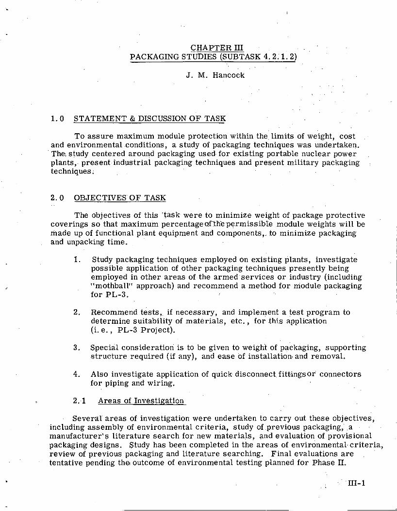
CHAPTER I11 PACKAGING STUDIES (SUBTASK 4.2.1.2) --
. .
J. M. Hancock
1 .0 STATEMENT & DISCUSSION OF TASK
To assure maximum module protection within the, limits of weight, cost . .
and environmental conditions, a study of packaging techniques was undertaken. The; study centered around packaging used. for existing portable nuclear power ,
plants,. present industrial packaging techniques and present military packaging ..
techniques;
2 .0 OBJECTIVES' OF TASK
The objectives of this 'task were to minimize weight of package protective coverings s o that maximum percentageof:tEe permissible .mod.ule weights will be made up of functional plant equipment and components,- to minimize packaging and unpacking time. . ,
1. Study packaging techniques employed on existing plants, investigate possible application of other packaging techniques presently being employed in other areas of the armed services o r industry (including lfmothballll approach) and recommend a method for module packaging for PL-3.
2. Recommend tests, if necessary, and implement a test program to determine suitability of materials, etc. , for this application (i. e. , PL-3 Project).
3. Special consideration is to be given to weight of pakkaging, supporting structure required (if any), and ease of installation. and removal.
4. Also investigate application of quick disconnect. fitti.ngs o r connectors for piping and wiring.
2 ..I Areas of Investigation
Several' a reas of. investigation were undertaken to carry out these objectives, ' including assembly of environmental criteria, study of .previous packaging, . a . . .
manufacturer's li terature search for new materials, and evaluation of provisional packaging designs. Study has been completed in the areas of environmental. cri teria, review of previous packaging and literature searching. Final evaluations a r e . '
tentative pending the outcome of environmental testing planned for Phase 11.
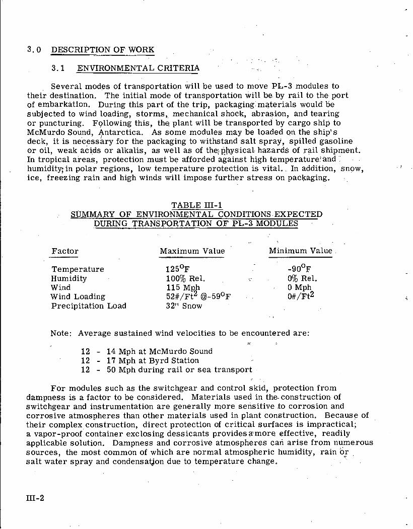
3.0 DESCRIPTION OF WORK "
3.1 ENVIRONMENTAL CRITERIA
Several modes of transportation wi l l be used to move PL-3 modules to their destination. The initial mode of transportation will be by ra i l to the port of embarkation. During this part of the trip, packaging materials would be subjected to wind loading, s torms, mechanical shock, abrasion, and tearing o r puncturing. Following this, the plant will be transported by cargo ship to McMurdo Sound, Antarctica. A s some modules may be loaded on the ship's deck, i t is necessary for the packaging to withstand sa l t spray, spilled gasoline o r oil, weak acids o r alkalis, as well a s of the,; physical hazards of rail shipment. In tropical areas , protection must be afforded against high temperaturecand humidity; in polar regions, low temperature protection is vital. .. In addition, snow, ice, freezing rain and high winds will impose further s t r e s s on packaging.
TABLE 111-1 .. SUMMARY OF ENVIRONMENTAL CONDITIONS. EXPECTED
DURING TRANSPORTATION OE" PL-3 MODULES .
Factor Maximum Value Minimum Value
Temperature 1 2 5 ' ~ - 9 0 ' ~ Humidity 100% Rel. -- 0% Rel. Wind 115 Mph 0 Mph Wind Loading 52#/Ft2 @I-5g°F o # / F ~ ~ Precipitation Load 32" Snow
Note: Average sustained wind velocities to be encountered a re : /
12 - 14 Mph at McMurdo Sound 1 2 - 17 Mph a t Byrd Station 12 - 50 Mph during ra i l o r s ea transport
-
For modules such as the switchgear and control skid, protection from dampness is a factor to be considered. Materials used in theconstruction of switchgear and instrumentation a r e generally more sensitive .to corrosion and corrosive atmospheres than other materials used in plant construction. Because of their complex construction, direct protection of critical surfaces is impractical; a vapor-proof container exclosing dessicants provides amore effective, readily applicable solution. Dampness and corrosive atmospheres can ar ise from numerous sources, the most common of which a r e normal atmospheric humidity, rain or sa l t water spray and condensat$on due to temperature change.
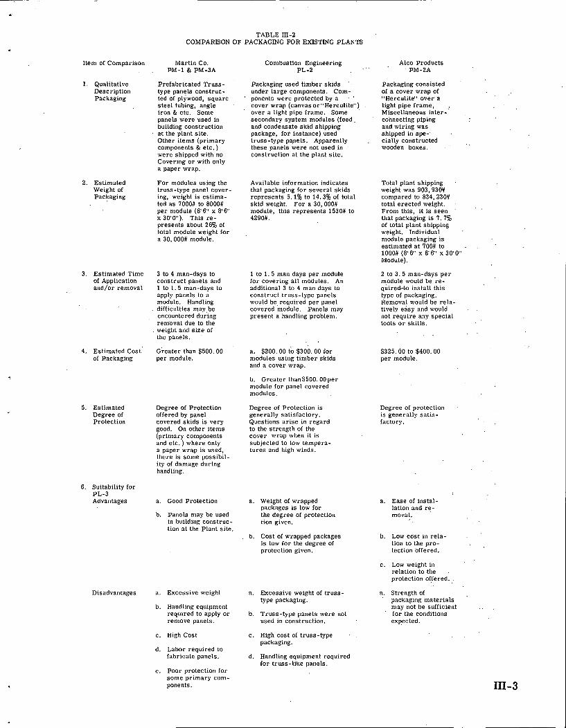
TABLE III-2 COMPARISON OF PACKAGING FOR EXISTING PLANTS
Item of Comparison Martin Co. , PM-1 & PM-3A
Combustion Engineering PL-2
Alco Products PM-2A
1. Qualitative Description Packaging
Prefabricated Truss- type panels construc- ted of plywood, squarc steel tubing, angle iron & etc. Some panels were used in building construction at the plant site. Other items (primary components & etc .) were shipped with no Covering or with only a paper wrap.
Packaging used timber skids '
under large components. Com- poncnts wcrc protcctcd by a '
cover wrap (canvas or"Hercu1ite") over a light pipe frame. Some secondary system modules (feed. and condensate skid shipping package, for instance) used truss-type panels. Apparently . these panels were not used in '
construction at the plant site.
Packaging consisted of a cover wrap of "Hcrculite" over a light pipe frame, . Miscellaneous inter- connecting piping and wiring was shipped in spe- cially constructed wooden boxes.
2. Estimated Weight of Packaging
For modules using the truss-type panel cover- ing, weight is estima- ted as 7000# to 8000# per module (8'6" x 8 ' 6 x 3 0 ' 0 ) . This re- presents about 26% of total module weight for a 30.000# module.
Available information indicates Total plant shipping that packaging for several skids weight was 903,930# represents 5.1% to 14.3% of total compared to 834,230# skid weight. For a 30,000# total erected weight. module, this represents 1530# to From this, it is seen '
4290#. that packaging is 7.7% of total plant shipping weight. Individual module packaging is estimated at 700# to . 1000# (8'6" x 8'6" x 30'0" Module).
3. Estimated Time of Application and/or removal
3 to 4 man-days to construct panels and 1 to 1 . 5 man-days to apply panels to a module. Handling
. difficulties may,be encountered during removal due to the weight and size 01 the panels.
1 to 1 . 5 man days per module for covering all modules. An additional 3 to 4 man days to construct truss-type panels would be required per panel covered module. Panels may present a handling problem.
2 to 3 .5 man-days per module would be re- quired-to install this type of packaging. Remova! would be rela- tively easy and would . . not require any special tools o r skills.
Greater than $500.00 a. $200.00 to $300.00 for per module. modules using timber skids
and a cover wrap.
$325.00 to $400.00 per module.
4. Estimated Cost of Packaging
b. Greater than$500.00per module for panel covered modules.
5. Estimated Degree of Protection
Degree of Protection offered by panel covered skids is very good. On other items (primary components and etc. ) where only a paper wrap is used, 111el.r is sollle yossibil- ity of damage during handling.
Degree of Protection is generally satisfactory. Questions ar ise in regard to the strength of the cover wrap when it is subjected to low tempera- tures and high winds.
Degree of protection is generally satis- factory.
6. Suitability for PL-3 Advantages a. Ease of instal-
lation and re- moval.
a. Good Protection a. Weight of wrapped packages is low for the degree of protection tion givcn.
b. Panels may be used in building construc- tion at the Plant site.
b. Cost of wrapped packages i s low for the degree of protection given.
b. Low cost in rela- . '
tion to the pro- tection offered.
c. Low weight in relation to the protection offered.
a. Strength of packaging materials may not be sufficient . . for the conditions expected.
Disadvantages a. Excessive weight a. Excessive weight of truss- type packaging.
b. Handling equipment required to apply or remove panels.
b. Truss-type panels were not used in construction.
c. High Cost c. High cost of truss-type packaging.
d. Labor required to fabricate panels. d. Handling equipment required
for truss-like panels. e. Poor protection for
some primary com- ponents.
I
Upon a r r i v a l at McMurdo Sound, the plant modules wil l b e s to red unprotected, except f o r t he i r packaging, f o r a period of six months t o one year . During th i s -
t ime , they wil l be subjected to low t empera tu re s , high winds; abras ion -and tear ing , and snow loads up to -25 pounds p e r s q u a r e foot. After this period of s to rage , the modules wil l be t ranported by air to the installat ion site at Byrd Station. The probable t h rea t s t o packaging during th i s phase of the t r i p are expected to be no a-
m o r e s e r i o u s than those encountered during previous p a r t s of the t r ip .
', . 3. r2 :: ""::Previous':Packaging Schemes
Packaging s c h e m e s and ma te r i a l s used f o r PL-1, PL-2, PM-1 and PM-BA and PM-3A w e r e evaluated f o r applicability t o PL-3 packaging requirements . Table 111-2 gives r e su l t s of this study and indicates per t inent cha rac t e r i s t i c s of var ious packago typos.
- . . . 3. 3..'.""~ManUfac.tur,ersS!. Liter.ature. Sea rch . . . ;i:;.
To obtain information on ma te r i a l s t h a t might be applicable to packaging of PL-3 modules, manufacturers ' l i t e r a tu re was reviewed. ~ a n u f a c t u r e r s w e r e con- tacted to obtain specif ic .data and recommendat ions f o r the i r mater ia l s . A p a r t i a l l i s t of the manufac turers f r o m whom information was obtained, includes:
Ace P las t ic Company Albano Honeycomb Division B a r c o Manufacturing Company Calumet and Hecla,. Inc. Dow Corning Corp. D r e s s e r Industr ies , Inc, E. I. DuPont De Nemours and Company The Duetsch Company Hansen Manufacturing Company Herculi te Pro tec t ivc Fab r i c s , Inc. Hexcel Products , Inc. . ~ o p p e r s Company, Inc. Met-L-Wood' Corporation Minnesota Mining and Manufacturing Company North Amer ican Avaiatidn, Inc. Pe rma l i , Inc. Raybes tos -Manhattan; Inc . Reeves .Bro thers , 1nc. Southern Elec t r ic , Inc. Spraylat Corporat ion Weyerhauser T imber Company Wheeling Corrugat ing Company
Data.obtained from these companies have shown that many suitable materials a r e available for use in packaging.
. . .
3.4 Military Packaging
Military packaging techniques examined utilized complete coutour following materials, the covering compounds applied by spraying, brushing, flow-coating, o r dipping, The compounds give satisfactory protection against most expected hazards, Special handling may be required in some cases because the materials a r e susceptible to abrasion damage from tie-down ropes. Coatings a r e generally applied in several layers; a t the destination, the covering is stripped o r peeled off. The coatings a r e soft and flexible over a normal range of temperatures (freezing to 125OF), but may be brittle and hard to peel a t very low temperatures (below -50'~). Solvents a r e used to remove some of these compounds, but this type of removal is tedious and messy. These compounds provide absolute vapor protection as long as the integrity of the cover is maintained; however, their lack of reusability makes them impractical for PL-3 application.
3 .5 Proposed Package Designs
Initially, seven package designs were cokidered. They made use of soft, flexible materials over a light f rame, stiff panels, and sprayed o r flow-coated materials. Fig. 111-1 illustrates some of the details associated with a package constructed of light flexible materials over a light frame. The frame may be constructed of 3/4-in. pipe o r conduit, o r from 1 -in. x 1;in.i. x 114 in.. aluminum llTfl or channel. Flexible synthetic materials a r e made by several manufacturers, including Herculite Protective Fabrics, Minnesota Mining and Manufacturing Co., Reeves Brother, Inc. and E. I. DuPont de Nemours and Co. The various'fabrics combine nylon o r glass cloth with polyvinylchloride, neoprene, "Hypalon" * o r one of several fluorocarbon resins to obtain strength, flexibility and water resistance.
Because of their varying composition, .the faQrics have different physical characteristics. Generally, vinyl-Coated nylon fabrics lose flexibility a t temperatures above the PL-3 design minimum (-40°F as compared with -90°F). Varying the vinyl compound to attain low te'mperature flexibility sacrifices .
desirable high temperature characteristics. The material may lose abrasion resistance o r become .soft and tacky.
A fabric made of nylon cloth coated with Hypalon on one side and neoprene on the other maintains flexibility to temperatures as low as -50°F. Neoprene surfacing on both sides extends low temperature flexibility to -67OF.
* E. I. DuPont de Nemours and Co. registered TM
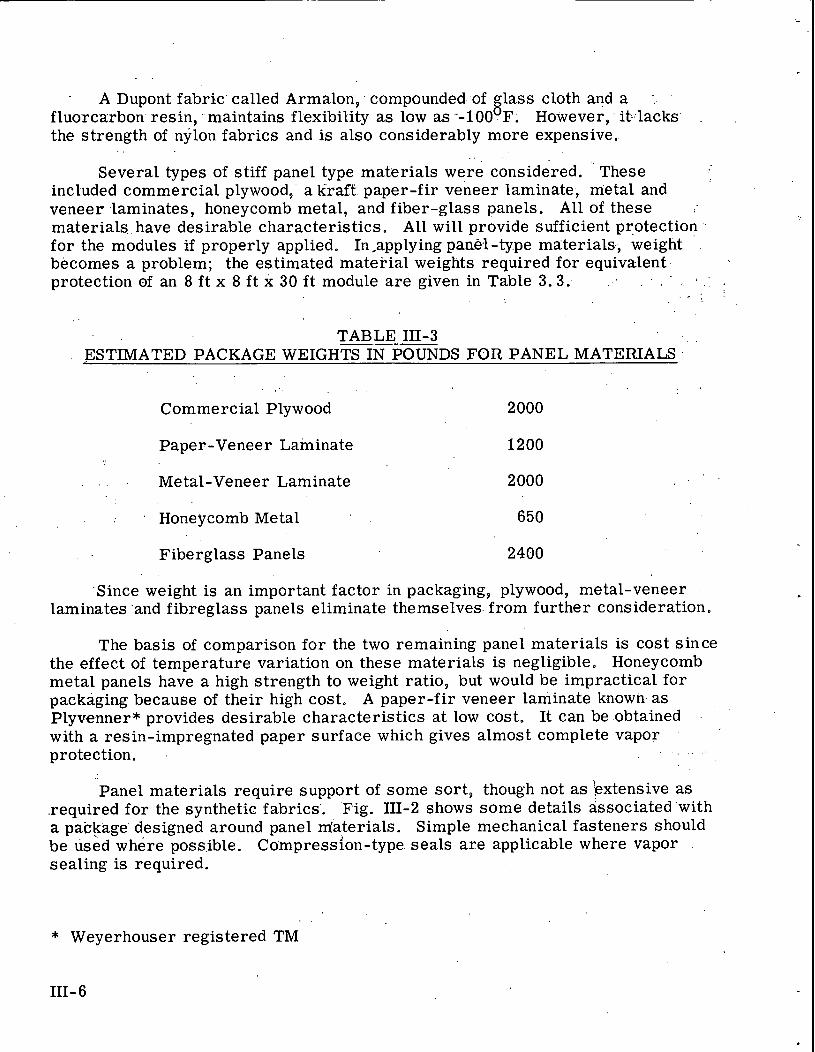
- A Dupont fabric' called Armalon, . comp.ounded of lass cloth and a . 8 fluorc.arbon. resin, maintains flexibility as low as --1.00 Fo However,. it-:lacks' .
the strength of nylon fabrics and is also considerably more expensive. . .
. .
Several types of stiff panel type materials were considered. ' These included commercial plywood, a kraft paper-fir veneer laminate, metal and veneer laminates, honeycomb metal, and fiber-glass panels. All of these materials have desirable characteristics. A l l will provide sufficient protection . for the modules if properly applied. In,applying panel-type materials,, weight . . becomes a problem; the estimated material weights required for equivalent protection. of an 8 ft x 8 ft x 30 f t module a r e given in Table 3.3. . . ._ . .
' , . '
TABLE 111-3 . .
ESTIMATED PACKAGE WEIGHTSINPXNDS FOR PANEL MATERIALS
. , , . . . Commercial Plywood 2000
Paper-Veneer Laminate 1200
. . Metal-Veneer Laminate 2000
Honeycomb Metal
Fiberglass Panels 2400
.Since weight is an important factor in packaging, plywood, metal-veneer laminates 'and fibreglass panels eliminate themselves. from further consideration.
The basis of comparison for the two remaining panel materials is cost since the effect of temperature variation on these materials is negligible. Honeycomb metal panels have a high strength to weight ratio, but would be impractical for packaging because of their high cost. A paper-fir veneer laminate k.nown a s Plyvenner.* provides desirable characteristics a t low cost. It can be .obtained .
with a resin-impregnated paper surf ace which gives almost complete vapor protection. . , .
Panel materials require support of some sort , though not a s 'extensive a s required for the synthetic fabrics'. Fig. 111-2 shows some details associatedwith a package designed around panel m'aterials. Simple mechanical fasteners should. be used where possible. Compression-type. seals a r e applicable where vapor .
sealing is required.
* Weyerhouser registered TM
111- 6
Spray o r flow coatings a r e available from several manufacturers. These materials.were to be app'lied over wire screen o r expanded metal grating tied to.supports around the package. When it became obvious that the material would not . f i l l the-'-interstices, the idea of applying the material directly to skid-mounted components was considered. Because of the complexity of some skids, this idea was considered impractical. Compounds intended to be strippable under normal conditions would be difficult, if not impossible,; to remove from complex shapes under .adverse conditions. Preparation of components and surfaces would be a time-consuming process, because screw heads, joints and other complex shapes must be filled with caulking compound o r covered with masking tape prior to . .
applying the spray compound. At normal temperatures ( 3 2 O ~ to 125OF), the compounds retain their'..: integrity and physical characteristics and can be easily pulled from covered surfaces. In a Polar environment, these coatings would .
become brittle and virtually unstrippable.
The last factor considered for the various initial package designs is reusability. For maximum reusability, packaging material should be applied so that removal is non-destructive. .-To meet this criteria, panel-type covering, simple mechanical fasteners, compression seals, prefabricated packaging supports and interchangeable package assemblies represent optimum packaging materials. Storage facilities within the snow tunnels o r in a separate building should be provided. Materials to be avoided are'sticky-.or gummy adhesives, materials that deteriorate with; time, one-time pac.kaging materials, . non-standard packaging units and packaging materials that require special handling equipment, al l of which may hinder reusability.
3. 6 Selected Package Designs
Two package designs have been considered worthy of further investigation and evaluation. The f i rs t of the two packages (see Fig. 3 . 1 ) utilizes a soft, synthetic fabric covering over a light frame. Several fabrics with similar physical characteristics a r e available. The advantages which led to the retention of this packaging scheme include ease of application and removal, reusability, light weight and low cost in proportion to strength, and adaptability to techniques of pre-fabrication. Disadvantages center around unknowns in regard to extreme low temperature behavior of the materials.
The second package (see Fig. 3.2) utilizes a stiff panel covering over a light frame. The panel covering considered is a laminate of resin-impregnated kraft paper and Douglas fir veneer marketed under the tradename of Plyveneer. * The-advantages of a package utilizing this material include reusability, ease of application and removal, relatively low weight and high strength in proporation to cost, retention of strength a low temperatures and adaptability to techniques of pre-fabrication. Disadvantages lie in the difficulty of obtaining a completely
* Weyerhauser registered TM
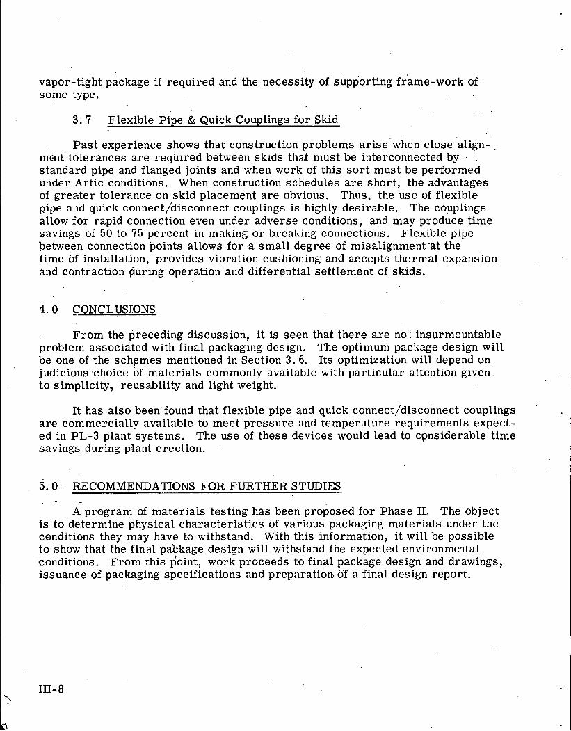
vapor-tight package if required and the necessity of supporting frame-work of some type,
3 , 7 Flexible Pipe & Quick Couplings for Skid
Pas t experience shows that construction problems a r i se when close align- ment tolerances a re required between skids that must be interconnected by . standard pipe and flanged joints and when work of this s o r t must be performed under Artic conditions. When construction schedules a r e short, the advantages of greater tolerance on skid placement a r e obvious. Thus, the usc of flexible pipe and quick connect/disconnect couplings is highly desirable. The couplings allow for rapid connection even under adverse conditions, and may produce time savings of 50 to 75 percent in making o r breaking connections. Flexible pipe between connection points allows for a small degree of misalignment-at the time of ins tallatipn, provides vibration cus hionlng and accepts thermal expans ion and contraction during operation and differential settlement of skids.
CONCLUSIONS
From the preceding discussion, i t is seen that there a r e no': insurmountable problem associated with final packaging design. The optimum package design will be one of the schemes mentioned in Section 3.6. Its optimization will depend on judicious .choice of materials commonly available with particular attention given to simplicity, reus ability and light weight.
It has also been found that flexible pipe and quick connect/disconnect couplings a r e commercially available to meet pressure and temperature requirements expect- ed in PL-3 plant systems. The use of these devices would lead to cpnsiderable time savings during plant erection.
5.0 - RECOMMENDATIONS FOR FURTHER STUDIES -
A program of materials testing has been proposed for Phase 11. The object is to determine physical characteristics of various packaging materials under the conditions they may. have to withstand. With this information, it will be possible to show that the final pakkage design will withstand the expected environmental conditions. From this $oint, work proceeds to final package design and drawings, issuance of packaging specifications and preparation,.of.-a final design report.
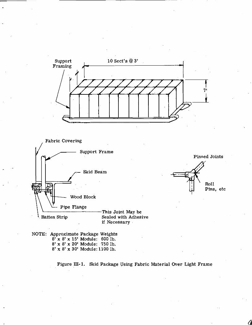
Support Framing
Fabric - Covering / r r , .
Support 'Frame
Wood Block
\ Pipe Flange This Joint May be
.\. Batten Strip Sealed with' Adhesive if Necessary
NOTE: Approximate Package Weights 8' x 8' x 15' Module: 600 1b. 8' x 8' x 20' Module: 750 lb. 8' x 8' x 30' Module: 1100 lb.
Pinned Joints +mil Pins , etc
Figure III- 1. Skid Package Using Fabric Material Over Light Frame
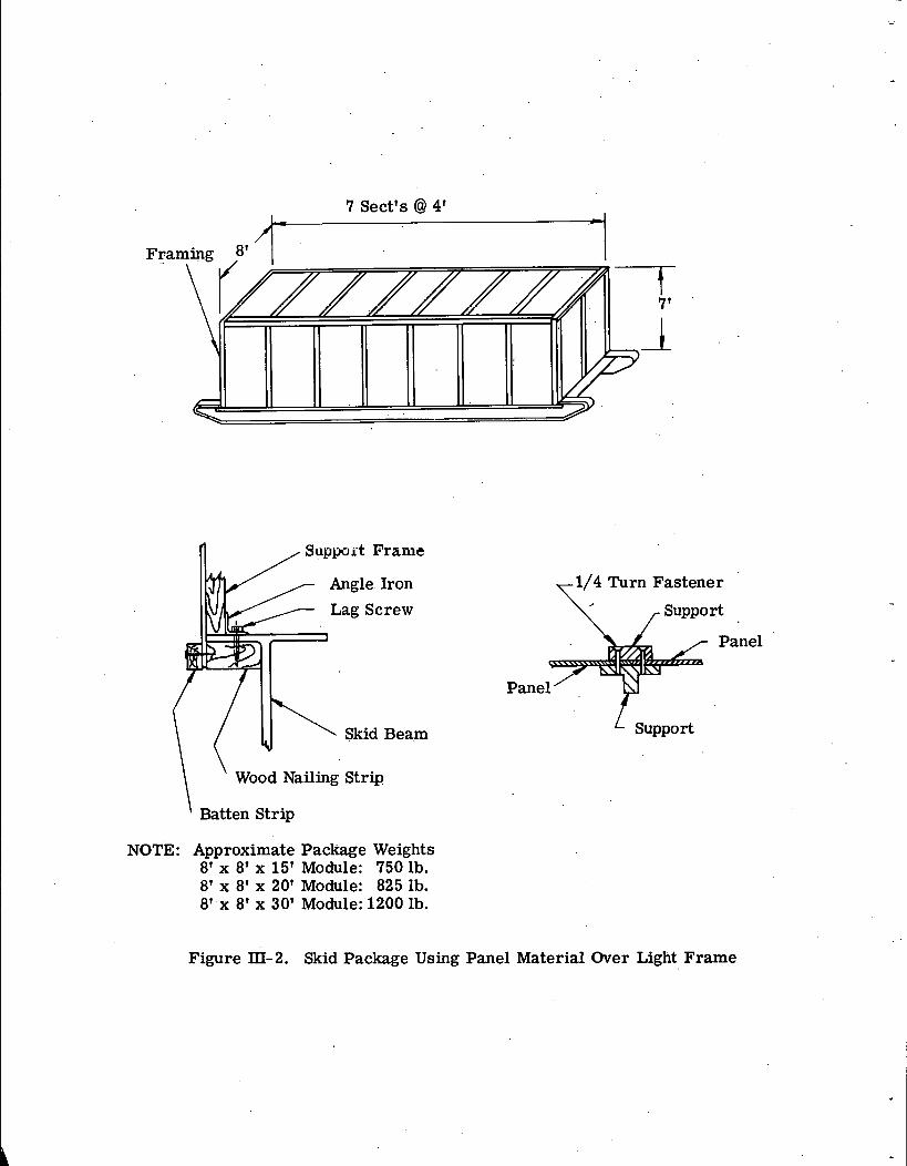
7 Sect's @ 4'
n Support Frainc /
1/4 Turn Fastener
Panel
1 suppo*
\ ' Wood Nailing Strip
' Batten Strip
NOTE: Approximate Package Weights 8' x 8' x 15' Module: 750 1b. 8' x 8' x 20' Module: 825 lb. 8'.x 8' x 30' Module: 1200 lb.
Figure III-2. Skid Package Using Panel Material Over Light Frame

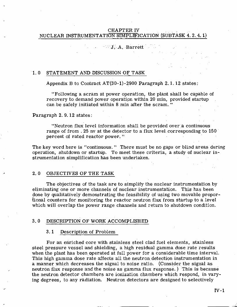
CHAPTER IV NUCLEAR INSTRUMENTATION SIMPLFICATION (SUBTASK 4.2.4.1)
1 . 0 STATEMENT AND DISCUSSION OF TASK
Appendix B to Contract AT(30-1)-2900 Paragraph 2.. 1.12 states :
"Following a sc ram at power operation, the plant shall be capable of recovery to demand power operation within 20 min, provided startup can.be safely initiated within 8 min after the scram. "
Paragraph 2. 9.12 states :
"Neutron flux level information shall be provided over'.a continuous. range of from .25 nv a t the detector to a flux leve1,corresponding to ,150 percent of rated reactor power. l1
The key word here is llcontinuous. l 1 There must be no gaps o r blind a reas during operation, shutdown o r startup. To meet these cri teria, a study of nuclear in- strumentation simplification has been undertaken.
2 .0 OBJECTIVES OF THE TASK
The objectives of the task a r e to simplify the nuclear instrumentation by eliminating one or more channels of nuclear instrumentation. This has been done by qualitatively demonstrating the feasibility of using two movable propor- tional counters for monitoring the reactor neutron flux from startup to a level which will overlap the power range channels and return to shutdown condition.
3.0 DESCRIPTION OF WORK ACCOMPLISHED
3 .1 Description of Problem
For an enriched core with stainless steel clad fuel elements, stainless steel pressure vessel and shielding, a high residual gamma dose ra te results when the plant has been operated at full power for a considerable t ime interval. This high gamma dose ra te affects all the neutron detection instrumentation in a manner which decreases the signal to noise ratio. (Consider the signal as neutron flux response and the noise as gamma flux response. ) This is because the neutron detector chambers a r e ionization chambers which respond, in vary- ing degrees, to any radiation. Neutron detectors a r e designed to selectively
respond to neutron radiation, but in the presence of high gamma fields, the response to gamma radiation is appreciable.
The effect;.: of gamma radiation on chamber response is shown in the accompany- ing Fig. IV-1. Representative chambers have been chosen from the "Neutron De- tector Handbook, l1 published by Bettis Atomic Power Laboratory. Neutron.flux range and gamma dose ra te operating limits for signal to noise ratio of 10 to 1 and 1 to 1 a r e shown. These a r e usually considered the operating limits for accept- able and unacceptable response.
Thermal neutron. density and gamma dose ra te at the B F counter position, 9 as a function of time after a s c r a q at SM-1 is shown in AP No e-128, * Fig. 1. Data have been extracted from this curve and plotted on Fig. N-1 to show the approximate decay curve followed after a scram. The time marks on this curve correspond to t ime after scram. It can be seen in Fig. N-1 that following a sc ram there is a period of t ime during which neither the intermediate range nor the source range can operate. This situation can be bettered somewhat by in- creasing the percent of compensation to a value near 99 percent. The .curves drawn a r e for 95 percent compensation, which is considered normal operation. Higher values of percent compensation require very stable voltage power supply, especially at the low neutron signal levels encountered at the bottom of the inter- mediate range.
There is the possibility of effecting a recovery to demand power within 20 min following a sc ram if the neutron flux does not go below the compensated ionization chamber range before the 8 min have eIapsed. The experience at SM-1 indicates this can be accomplished. The procedure followed at SM-1 is rather sensitive, (though acceptable) and a more precise scheme for accomplish- ing the startul?;' after sc ram is desirable.
3. 2 Possible Solutions
There a r e two methbds of solving the problems mentioned. One is to pro- vide shielding which diminishes the gamma dose rate; theother is to provide two movable proportional counter channels and move theic chambers out of the high gamma field while remaining within readable neutron flux limits. The first method follows the conventional approach to neutron flux indication and is dis- cussed in the preliminary design reports.
The other method, t o provide two movable proportional counter channels to indicate neutron flux over the entire operating range, is not entirely new but .
is not known to have been applied to power reactor instrumentation as yet. One of several possible reasons for this is unknown technical difficulties. Because of this, a literature survey should be made to ascertain that the tes ts described
* Page, E. , "Gamma Dose and Neutron Levels for Short Times After Shutdown .. at BF3 Counter Positions, l1 Alco Products, Inc. , AP ~ o t e - 1 2 8 , February, 1959.
here have not already been performed at some other facility and the results found unsatisfactory. The balance of this report describes a test program and gives ex- pected results assuming that the work has not been done elsi6where.
3 .3 Descr i~ t ion of Test Program
The test program consists of two complete individual channels of neutron detection. Both channels a r e exactly similar insofar as equipment is concerned. The channels will operate in the count range, (or source range) the most sensi- tive range for neutron detection. Continuous monitoring .of neutron flux over the complete range of approximately 12 or 13 decades will be accomplished by moving the detector further away from the core as flux increases. This motion would be effected in the shield tank adjacent to and above the reactor on a line with the core.
The tes t setup consists of a reactor of the swimming pool research type capable of producing a thermal neutron flux of the order of 1013 nv. Two neutron detector chamber wells would be installed on a line with the reactor core. A lift mechanism would be provided above the wells. The chamber assembly and at- tached cables would be lowered into the well and the cabling connectedto the remainder of the neutron detection channel consisting of the amplifying and computing electronics necessary for readout o r indication. This electronic circuitry is separate from the facility instrumentation to allow the operatton of the reactor by the facility personnel using the normal facility instrumekation.
Several neutron flux plots through a light water moderator have been cal- culated in- APAE Memo-247. * The results of these calculations show an average
..of about one decade of thermal neutron flux attenuation for five inches of water. Thus, 12 or 13 decades of neutron- flux can be covered with approximately 5 o r 6 f t of travel.
The tests consist of alternately changing the position of two proportional counters. At the bottom of the range, both counters a r e full in. As the power is increased to about half the range of both counters, one of them is moved s o it indicates.a low count rate again. The power is increased further while both channels indicate until the top of the as yet unmoved counter is reached and it is then moved to a position which obtains counts equal to the previously moved chamber. This position is recorded and both chambers a r e in equal neutron flux: position. Then the sequence is continued. The test procedures which follow and Fig. IV-2 illustrate the operation further. The test, procedure assumes the installation has been completed and all calibrations have been 'completed.
, .
* Crouch, A. N. , "SM-2 Primary shield Survey, l 1 ALCO Products, Inc. , APAE Memo-247, February, 1960.
3 . 4 . Test Procedure . t . .. . ..
1.. Both tubes full in. Source inserted and count ra te a t least 2 cpsi :
2. Withdraw safety rods, i f any - observe new core multiplication on both channels'- each channel may not read the same. Par t of the develop- ment program will require placing the wells in such a position that ap- proximately equal count rates will result in corresponding ppsitions.
3. Increase flux by 3 decades by withdrawing rods obser;ing the usual safety precautions. This should result in a count ra te of approximately 2000. cps: '
4. Withdraw Chamber 2 to a height which results in a count rate of 20 ~ p s ... Record this movement. It should be approximately 15 inches. This corresponds t o position. 2 on Fig. IV-2.
5. Proceed up in flux ra te for 2 more decades. The chamber which was not moved, Chamber 1, should be nearly saturated ((2 (x:.&o5;, cps)l. L The chamber which was' moved, Chamber 2, should read approximately 2000 :icps,.. (Still Position 2. )
6. Move chamber 1 up until a count rate of 20 cps is achieved (should required about 25 in. of movement). This corresponds to Position 4. Positions 3 and 5 a r e for recording purposes only.
7. Increase flux until Chamber 2 reads 2 x lo5 cps - chamber 1 approxi- mately 2000 cps. (Still Position 4. )
8. Move Chamber 2 until the count ra te is 20 cps.
9. Increase flux until Chamber 2 reads 2000 cps and . Chamber 1 approxi- mately 2 x 10⁵ cps. Continue process until approximately 12 o r 13 decades of neutron flux has been traversed (Position 7 o r more).
The value of inches stated and shown in Fig. 2 assumes 5 in. of travel for one decade of thermal neutron flux, and is subject to further checks including the results of this test.
3 . 4 Problem Areas
There a r e several problem areas associated with.this scheme which can be identified at this time. These problems a r e concerned with the neutron flux difference between the test setup and actual power reactor installation, cable flexing and noise problems, system reliabiritji, . and human e r r o r susceptibility. The following describes procedures which will be used.to .investigate these problems.
3. 4 . 1 Neutron Flux Investigation
1. Select the test reactor.
2. Obtain unperturbed flux plots and gamma dose ra tes vs distance from core by means of wire o r foil t raverse.
3. Compare (2) with calculated values for PL-3 reactor and pressure vessel design.
4. Examine feasibility and necessity of mocking up a portion of the proposed pressure vessel and shielding.
5. Obtain equipment necessary for the instrument channels, such as the de- tector well, detector lift mechanism, cables, electronic equipment, etc. , and install in the test facility.
6.. Calibrate instrumentation against foil t raverses. New foil t raverses may be necessary if the test equipment installation causes serious deformation .of the flux plots found in (2).
3 . 4 . 2 Flexing Cable Problem
1. Make impedance tes ts and pulse reproduction tes ts on the cable before installation, during movement with the lift mechanism, and after in- stallation.
2. Record neutron flux while moving the chambers up and down in the well by using the lift mechanism.
3. Make cycled flexing tes ts on the cable.
4. Investigate the possibility of converting. long cable runs-to-kucrent instead . ,
of voltage systems. This can be done by investigating new concepts in detector types and electronic circuitry.
3. 4 . 3 System ~ e l i a b i l i t y 'and Human Error Susceptibility
1. Obtain completely proven mil spec equipment o r be reasonably su re of its availability during the. plant construction.
~ 2. 'Perform equipment component tes ts and calibrations a t vendors shop and at test facility.
3. Require cycling tests of a fatiguing nature such as temperature, humidity, supply voltage changes, etc. before installation in.th-e plant. . '
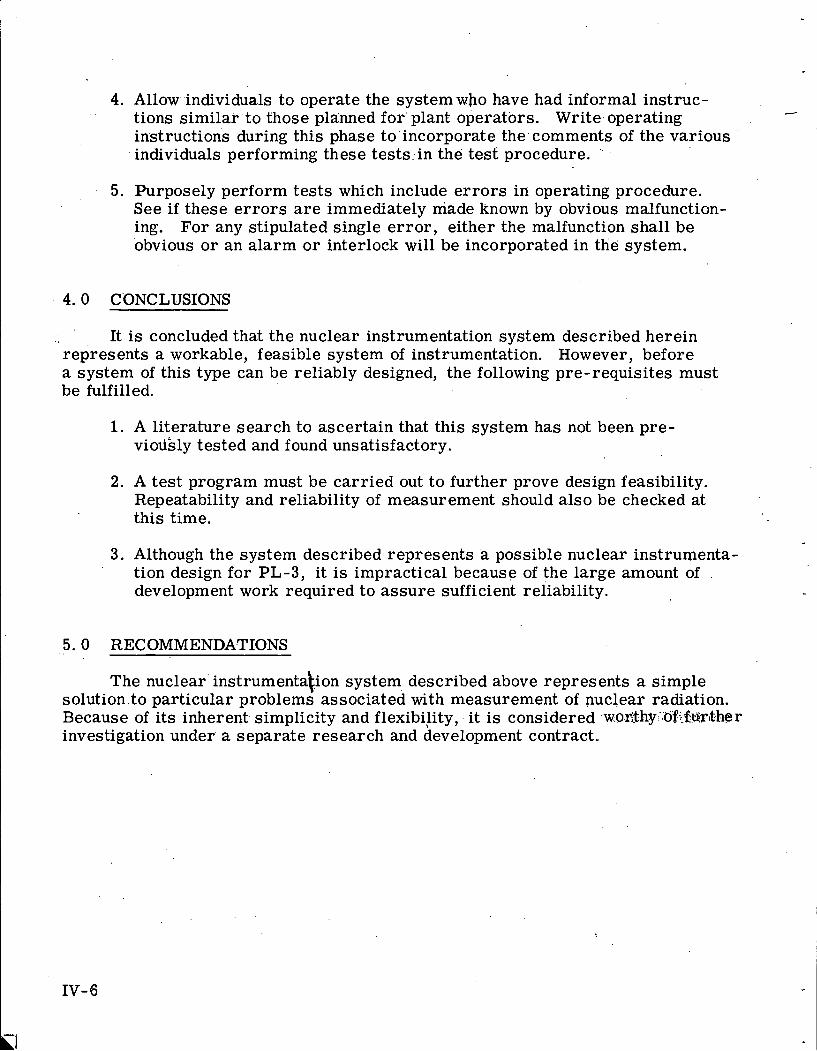
4. Allow individuals to operate the systemwho have had informal instruc- tions similar ' to. those planned for' plant operators. Write. operating +
instructions during this phase to'incorporate the.comments of the various '
individuals performing these tests:in the test procedure. ',
5. Purposely perform tes ts which include e r r o r s in operating procedure. See i f these e r r o r s a r e immediately made known by obvious malfunction- ing. For any stipulated single e r ro r , either the malfunction shall be obvious or an a larm o r interlock will be incorporated in the system.
4. 0 C'ONCLUSIONS
It is concluded that the nuclear instrumentation system described herein represents a workable, feasible system of instrumentation. However, before a system of this type can be reliably designed, the following pre-requisites must be fulfilled.
1. A l i terature search to ascertain that this system has not been pre- viodsly tested and found unsatisfactory.
2. A tes t program must be carried out to further prove design feasibility. Repeatability and reliability of measurement should also be checked at this time.
3. Although the system described represents a possible nuclear instrumenta- tion design for PL-3, it is impractical because of the large amount of development work required to assure sufficient reliability.
The nuclear' instrumentation system described above represents a simple solution to particular problems associated with measurement of nuclear radiation. Because of its inherent simplicity and flexibility,. i t is considered -w.o2$hy:;6fiedftt.her investigation under a separate research and development contract.
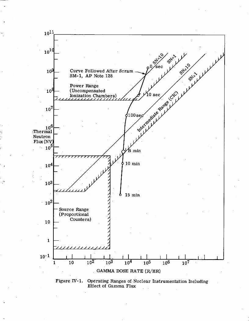
. GAMMA DOSE RATE (R/HR)
Figure IV-1. Operating Ranges of.Nuclear Instrumentation Including Effect of Gamma Flux
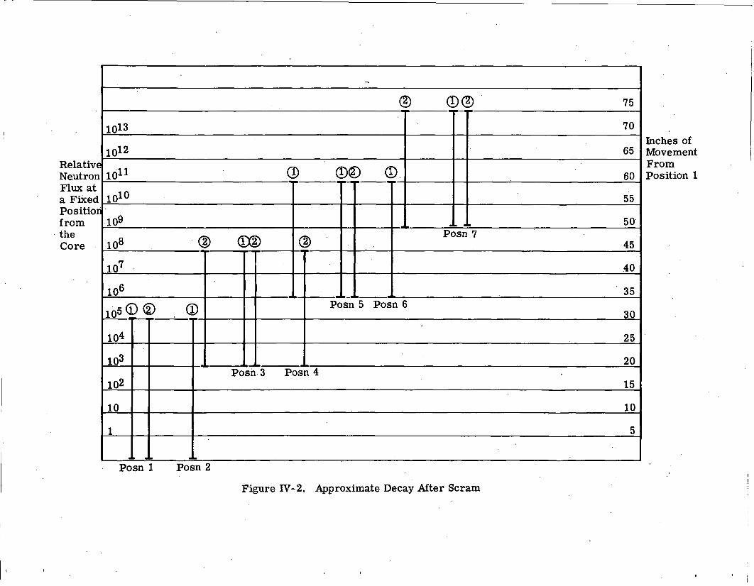
Inches of Movement From Position 1
Figure W- 2. Approximate Decay After Scram

V-9 V- 20
wall panels could have been somewhat thinner than four inches, a four.inch.pane1 wa-s used because of insulation requirements. The tri'al design indicates that .a four-inch wall panel a n d a six-inch roof panel a r e adequate to support the struc- tural design. loadings without auxiliary framing.
4 . 0 CONCLUSIONS
At the present time, the following conclusions have been reached regarding the building superstructures :
1. All buildings, except the reactor and Cooler buildings, shall be frame- less structures consisting of moment resisting roof and wall panels as- sembled as rigid f rame bents.
2. The reactor and cooler buildings must be metal-framed structures because of the heavy loads and special considerations involved.
3. Stressed skin wood panels appear to be the optimum construction, but because of cost uncertainties, metal siding panels o r plastic- faced s t ressed skin panels might qualify. Recommended procedure- would be to prepare bidding drawings based ons t ressed , skin'wood panels, but allow bidders to submit alternative designs to match the s t ressed skin panel cost and performance and'fulfill all specified requirements.
4. Vapor bar r ie r s of impervious material and resistant to ripping .and abrasion should be installed at the interior surface of the walls or ceiling. Closure between panels should be effected with pressure ... sensitive tape protected with gasketed battens.. A positive electrical ground connection between metal surfacing materials, if used, will be required.
5. Joints between panels should be of the tongue-and-groove type (unless panels a r e to be removed) with compressible gaskets and held'together with cam locks, exterior locks or longitudinal through bolts which do not pierce the vapor bar r ie r (see Fig. V-5).
6. Large doors for equipment erection access a r e not warranted. Re-. movable panels should be used.
7. Exterior doors should swing out, be gasketed and be equipped with gasket defrosters and quick-acting hardware.
8. Exterior doors should be heat trapped with a vestibule and-swinging inner doors .-
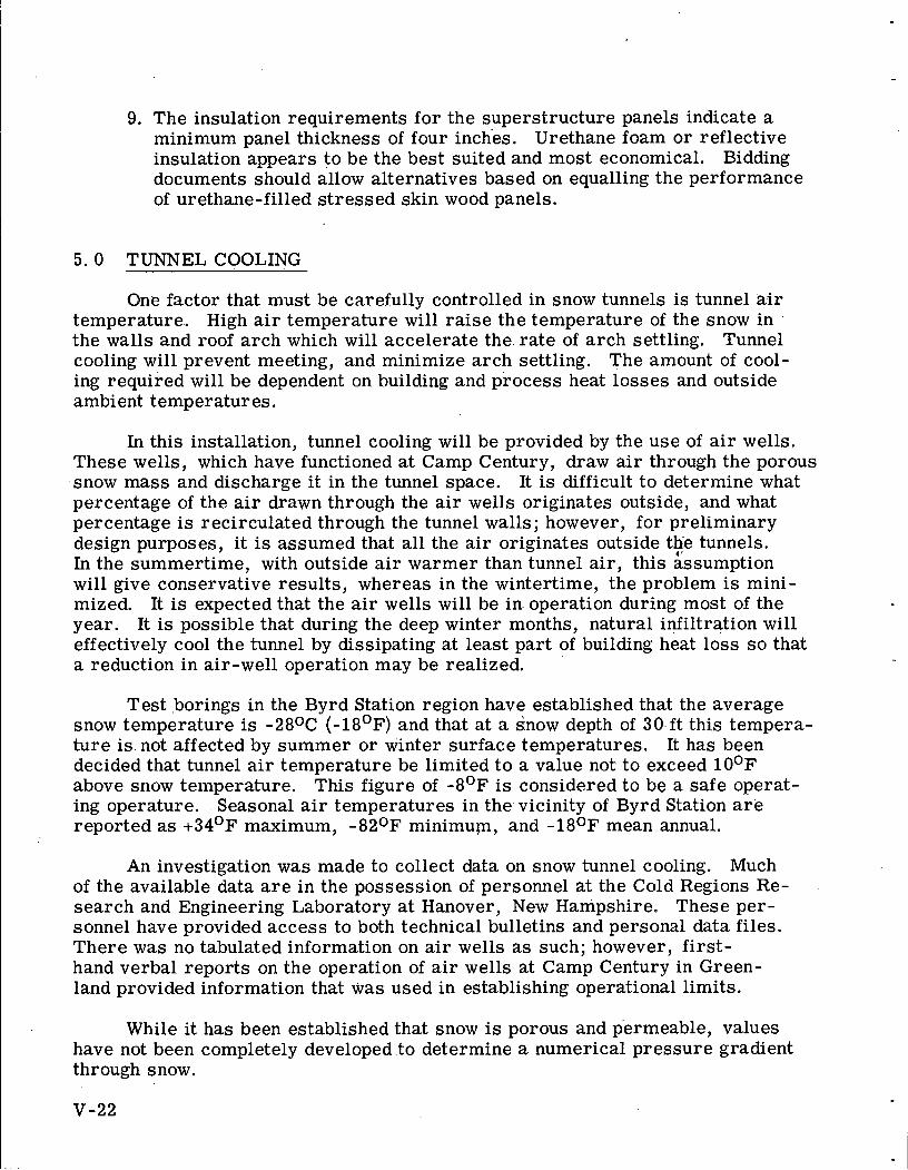
9. The insulation requirements for the superstructure panels indicate a minimum panel thickness of four inches. Urethane foam or reflective insulation appears to be the best suited and most economical. Bidding documents should allow alternatives based on equalling the performance of urethane-filled s t ressed skin wood panels.
5 .0 TUNNEL COOLING
One factor that must be carefully controlled in snow tunnels is tunnel air temperature. High air temperature will ra ise the temperature of the snow in the walls and roof arch which will accelerate the rate of arch settling. Tunnel cooling will prevent meeting, and minimize arch settling. The amount of cool- ing required will be dependent on building and process heat losses and outside ambient temperatures.
In this installation, tunnel cooling will be provided by the use of air wells. These wells, which have functioned at Camp Century, draw air through the porous snow mass and discharge i t in the tunnel space. It is difficult to determine what percentage of the air drawn through the air wells originates outside, and what percentage is recirculated through the tunnel walls; however, for preliminary design purposes, it is assumed that all the air originates outside th'e tunnels. In the summertime, with outside air warmer than tunnel air, this &sumption will give conservative results, whereas in the wintertime, the problem is mini- mized. It is expected that the air wells will be in operation during most of the year. It is possible that during the deep winter months, natural infiltration will effectively cool the tunnel by dissipating a t least part of building heat loss s o that a reduction in air-well operation may be realized.
Test .borings in the Byrd Station region have established that the average snow temperature is -28OC (-18'~) and that at a snow depth of 30.ft this tempera- ture is. not affected by summer or winter surface temperatures. It has been decided that tunnel a i r temperature be limited t o a value not. to exceed ~ O O F
above snow temperature. This figure of I OF is considered to be a sa fe operat- ing operature. Seasonal air temperatures in the- vicinity of Byrd Station a r e reported as + 3 4 O ~ maximum, -820F minimup, and -18OF mean annual.
An investigation was made to collect data on snow tunnel cooling. Much of the available data a r e in the possession of personnel at the Cold Regions Re- search and Engineering Laboratory at Hanover, New Hampshire. These per- sonnel have provided access to both technical bulletins and personal data files. There was no tabulated information on air wells a s such; however, first- hand verbal reports on the operation of air wells at Camp Century in Green- land provided information that was used in establishing operational limits.
While it has been established that snow is porous and permeable, values have not been completely developed to determine a numerical pressure gradient through snow.
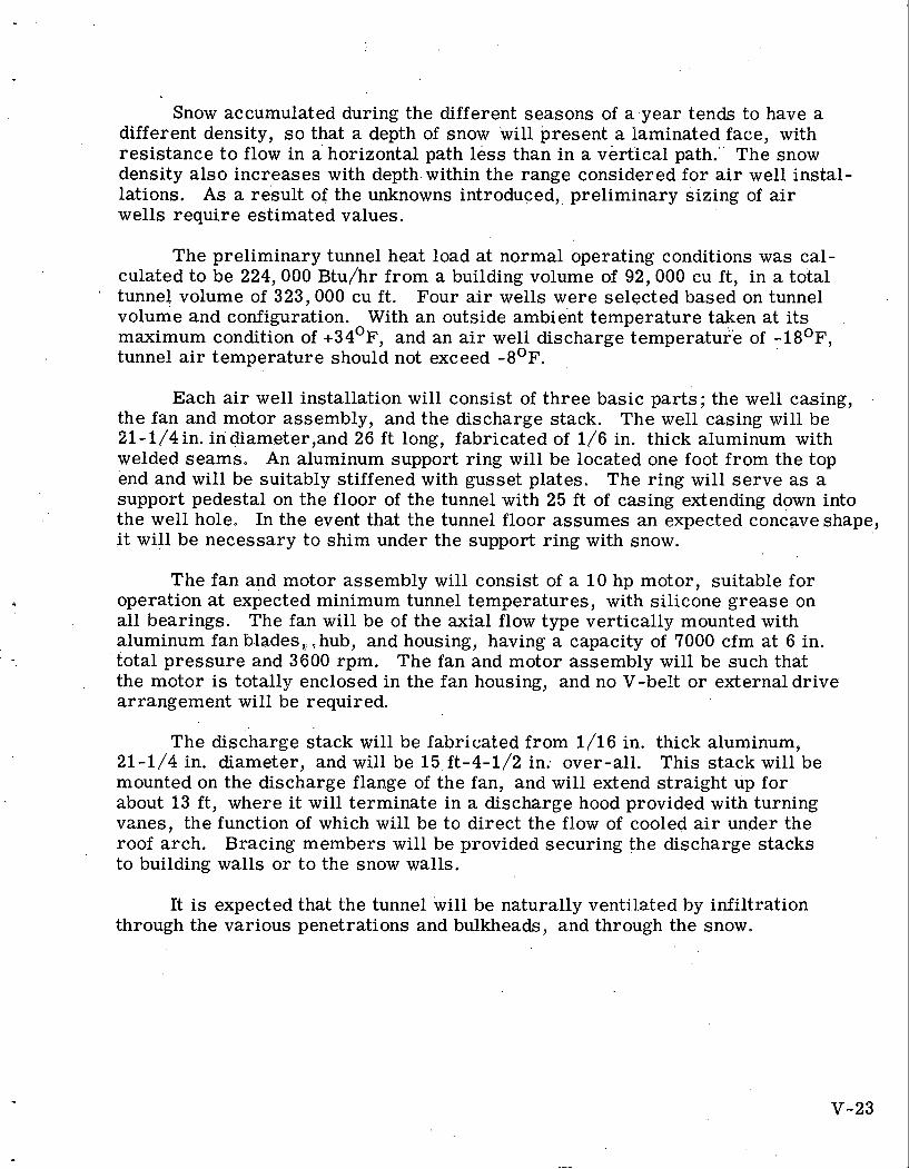
Snow accumulated during the different seasons of a , y e a r tends to have a different density, s o that a depth of snow will present a laminated face, with resistance t o flow in a horizontal path less than in a vertical path." The snow density a lso increases with depth. within the range considered for a i r well instal- lations. As a result of the unknowns introduced,, preliminary sizing of air wells require estimated values.
The preliminary tunnel heat load a t normal operating conditions was cal- culated to be 224,000 Btu/hr from a building volume of 92,000 cu f t , in a total
a tunnel volume of 323,000 cu f t . Four air wells were selected based on tunnel volume and configuration. With an outside ambient temperature taken a t i t s maximum condition of +34OF, and an air well discharge temperature of - 1 8 O ~ , tunnel air temperature should not exceed -8 '~ .
Each air well installation will consist of three basic parts; the well casing, the fan and motor assembly, and the discharge stack. The well casing will be 21-1/4 in. in diam.eter,and 26 ft long, fabricated of 1/6 in. thick aluminum with welded seams. An aluminum support ring will be located one foot from the top end and will be suitably stiffened with gusset plates. The ring will se rve as a support pedestal on the floor of the tunnel with 25 ft of casing extending down into the well hole. In the event that the tunnel floor assumes an expected concaveshape, it will be necessary to shim under the support ring with snow.
The fan and motor assembly will consist of a 10 hp motor, suitable for operation a t expected minimum tunnel temperatures, with silicone grease on all bearings. The fan will be of the axial flow type vertically mounted with aluminum fan blades, ,hub, and housing, having a capacity of 7000 cfm at 6 in. total pressure and 3600 rpm. The fan and motor assembly will be such that the motor is totally enclosed in the fan housing, and no V-belt o r external drive arrangement will be required.
The discharge stack will be fabricated from 1/16 in. thick aluminum, 21-1/4 in. diameter, and will be 15, ft-4-1/2 in; over-all. This stack will be mounted on the discharge flange of the fan, and will extend straight up for about 13 f t , where i t will terminate in a discharge hood provided with turning vanes, the function of which will be to direct the flow of cooled air under the roof arch. Bracing members will be provided securing the discharge stacks to building walls o r to the snow walls.
It is expected that the tunnel will be naturally ventil.ated by infiltration through the various penetrations and bulkheads, and through the snow.
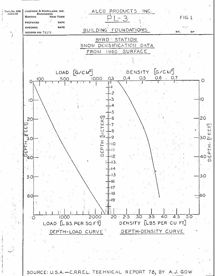
I 'j
" DATE
ALCC P,RODVCTS .INC. \ . -- -. - - .
FIG. 1
B Y R D ' - STATION i
S N 0 V . J DL14 S 1FICATIOI;I DATA FROI\;I i 9 6 0 S U R F A C E
! CHECKED ' . DATE \ \.:;..
RECORD NO. 7353 B U,I L D I NG' F o u N DATI ON^ SH. O F '
. .
DEP'TH-LOAD C U R V E ' D EPTH-DEI~JSIT'Y C'U R V E . .
. .
. ! ', W
. . . . .
I
SOURCE: U.S.A.-C.R.R.E.L. TECHbI ICAL R EPOHT 78, BY A. J. GOMf
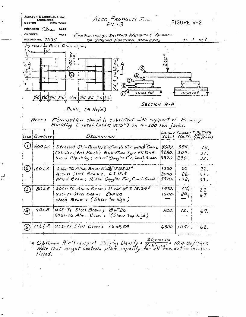
F'IGURE V-2
& ~ T P : F6unds-l.rbn shocvr; i s cobs;d-Fcnenf wt'fh suppor-f o f Pt,i':n.r-
B0/'/d/hq ( To.ta/. Load & ffji.rgtc) on 4 - 100 To/, .iacks, Y
.................................... ..................
1 ' .
-'-' ------. 3' 8OL.F G O & / - T 6 A/um. fic,irn : &" 'x~/~ ' ' * r@ 1 8 . 3 ~ ~ 2 2. L(sSiT/ Sfeel G e a m : d j ~ i 2 0 6 7. ~ o ~ d B e a m : ( S h e a r !too :/rthh )
.. * '36 0,+fi,31 ,,! /);c * f i . ~ - , , , ~~~ ' f ,.; :? ,'! ,$rl.ibJ D~~~ ;$ : ,
x p x 20' .. ~0ih f h d w c G h t cbrat,-o/s P / $ X ~ cdl7dc;f f o r a// /.bu,,da / J ~ J ~ r,ri...!;,:,: /Y //>Ted.
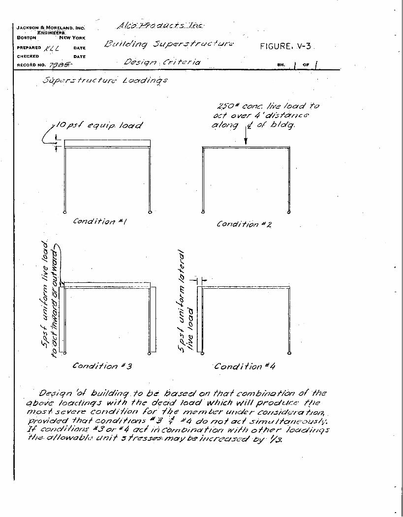
, ... .. . .
~ ~ ~ A C K B O . N . ~ ~ ~ , O R E ~ A N D ; E,m,HPGhia: i ~ e : ../:kb:.;uia CI'UC. ts /.n.c:-. BOSTON N m YORK
PREPARED ,(/L/ L DATE .&7~/i/~/,i7g ~ ( P C T S J7u c ;)UCC' FIGURE, .V-3 CHECKED ' DATE
RECOAD NO. m,9.6- - b'es/+fl , &) fcr id ' .. . , 8 n: oc
Depiqn 'ot bui/dinq. to b C based on /,ha+ ~umb/j/B t/&n of t l 7 e
' ~ b o k /oarJ/rq.s wi th thc dead load w/~/ch wi// prod~Acc f(le IT? 0s -/! 5 c vere C O ~ , dl' 7//b/1 /br /b a mer7, A6r u, >u/e 1- C O , ~ J , ~ ~ , . , Q dI0/7, prov.d/ed fhaf cond/'f/cws #3 7 &4 do no+ o c f s i m c ~ / f c r / , e : - c . ~ u s / I ; . j , ~ ; !4 r&~d i / io~~. r d 3 4 OC/ id CD,,, b ; ~ ~ j f / 7 o f ~ P T i ~ ~ d i / / ~ s t/ id s//owab/c wni f s ~~cs .sc . ( may & j/2crC3a3L-d by yJ /j: '
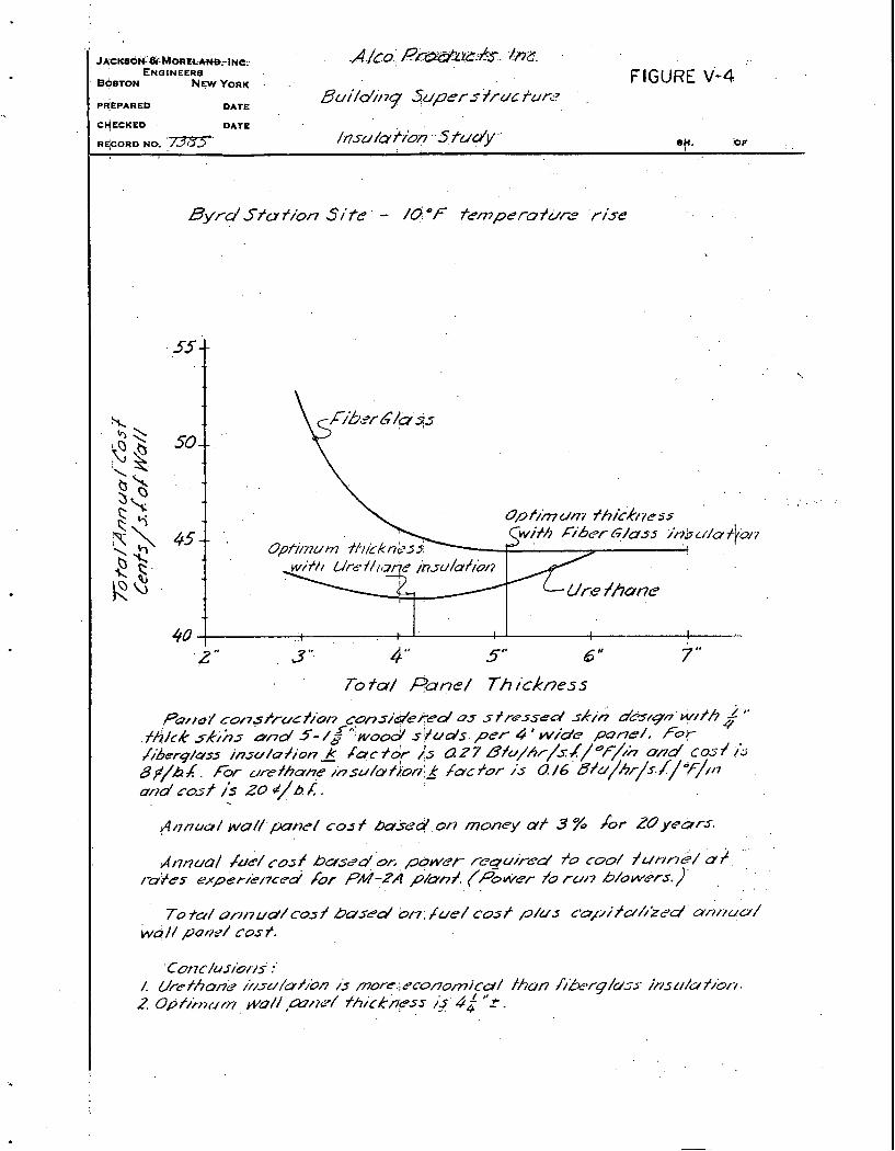
. / c . . p ' ~ 2 . JAcK~o~&&&~NIOREC-AW,-IN~;. . . ' ENGINEERS
BC$STON NWYORK . - . FIGURE V-4 P"PARED DATE
Bui/d/i 7~ Juper s ?rut fur27 ' .
Byrd J to f ion S /' te ' -. /d O F temperu f u e ' r ise . .
PQHE/ con~/ru~f ibn considered 0.s s /ra>sed skjh dlqn w//h & '' .ffi/ck &;As md 5 - / g 5 w o & s!+uds.per 4'wide pone/, f o ~
/iBer4/o5s jnsu/ofion_* & c t O r jS a 2 7 8 f ~ / h / / ~ j / ~ - / / n ~ n d C O S ~ ?'> B$/hk. Fw u r e i h o ~ /hsu/o/loni_*i /c/or i s 0 / 6 ' ~ f 0 / h r / s / / ~ ~ / / , ~ u/~d ros f i s 20 cc/b. A. . ~ 8 onw/ w o / / . p ~ ~ e / cos + b03cd or) money at 3 % /or ZOyebrs
i i I Anna/ be/ rosf busLsd & p g ~ c r r i u i r e d h coo/ /ur j /-~e/ a?. .'
m?es exper/e/7c~d /or PM? pbnj. . (POW . jo r u / 7 b/owc+rs.)'
To to/ or//-/ ud/ cos f b~sea ' 017; /ue/ C O ~ J . ~ / U J capif &//id' O~/?L(O/
w4/ / poflf / COS t.
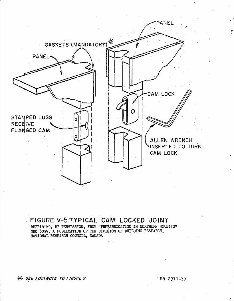
FIGURE V-5 T Y P I C A L C 4 M LOCKED J O I N T REPRINTED, BY PERMISSION, FROM ffBREpABRICATION I N NORTmRN HOUSING'I NRO 6059, A PUBLICATION OF THE D ~ I S I O N OF BUILDING RESEARCH, NATIONAL RESEARCH COUNCIL, CANADA
%. SEE FOOTNOTE TO FIGURE 9

CHAPTER VI ANTIFREEZE COOLANT STUDY (SUBTASK 4.2.3; 2)
C, R. Bergen .
1.0 STATEMENT AND DISCUSSION OF TASK
The PL-3 condenser and .,;uxiliarjks were anticipated to reiuire heat re- moval through air blast coolers to the atmosphere. . A suitable coolant for 'this purpose had to meet requirements of low temperature operation and radiation stability. Therefore, studies were initiated to evaluate the various coolants available, giving consideration to the special. requirements of both. BWR and PWR systems. . This subject is covered in more detail in.AP Note-407. *
2.0 OBJECTIVE OF TASK 3 .
: i . 1 The objective of the task is to investigate substitute antkfreeze coolant fluids for ethylene- glycol.
3.0 DESCRIPTION OF .WORK ACCOMPLISHED
For guidance in coolant selection, the properties listed in Table VI-'1 were chosen as a basis for comparison. The investigation of coolants centered on a study of manufacturersP literature. Of thirty coolants initially investigated, only nine had sufficient merit for further consideration. T ~ b i e VI-1 lists the properties of th&se coolalits.
Low temperature limitations were considered of primary importance. Only those. materials which had freezing points below- 6 5 O ~ were consi,dered, since this temperature can readily be met by 60 percent.aqueous ethylene glycol. (used as reference material).
The most stable of the materials, with respect to radiation, were mono- isopropyl biphenyl and silicate ester. These two materials tolerate more than ten times the radiation of the other materials. The other coolants exhibit the usual radiation resistance of organic compounds ( 1 o8 R gamma).
* Bergen, C. R., "Antifreeze Coolants; A Review of Manufacturersv Literature, I '
Alco Products, Inc. , . AP Note - 407.
VI- 1
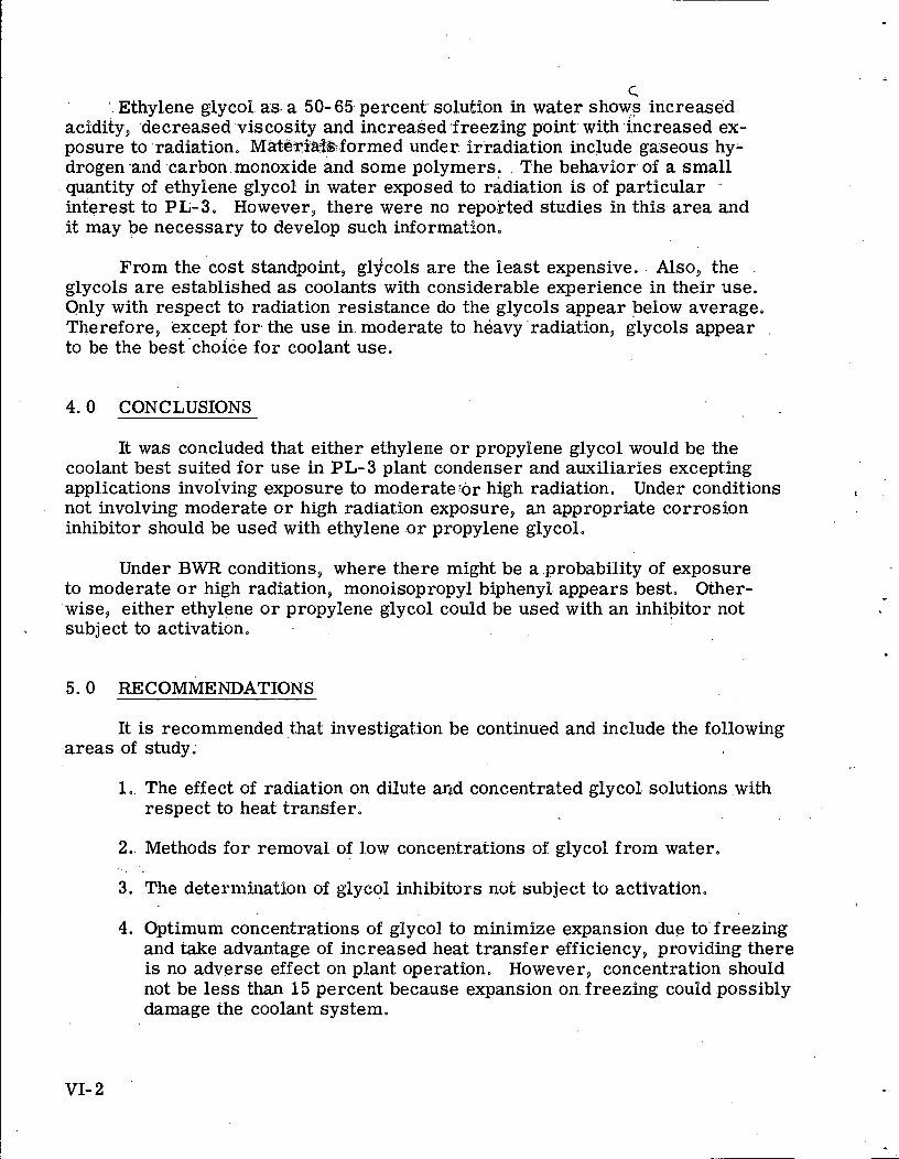
c; Ethylene glycol as a 50-65 percent solution in water shows increased
acidity, decreased viscosity and increased freezing point with increased ex- posure to radiation. MaterihlBformed under irradiation include gaseous hy- drogen-and carbon monoxide and some polymers. The behavior of a small quantity of ethylene glycol in water exposed to radiation is of particular interest to PL-3. However, there were no reported studies in this area and it may be necessary to develop such information.
From the cost standpoint, gljcols a re the least expensive. . Also, the .
glycols a r e established a s coolants with considerable experience in their use. Only with ,respect to radiation resistance do the glycols appear below average, Therefore, except for. the use in. moderate to heavy radiation, glycols appear to be the best'chofce for coolant use.
4.0 CONCLUSIONS
It was concluded that either ethylene o r propylene glycol wou1.d be the coolant best suited for use in PL-3 plant condenser and auxiliaries excepting applications involving exposure to moderateSor high radiation. Under conditions a
not involving moderate o r high radiation exposure, an appropriate corrosion inhibitor should be used with ethylene o r propylene glycol.
Under BWR conditions, where there might be a .probability of exposure to moderate o r high radiation, monoisopropyl biphenyl. appears best. Other- 'wise, either ethylene o r propylene glycol could be used with an inhibitor not subject to activation.
5.0 RECOMMENDATIONS
It is recommended ,that I'nvesti.gation be continued and include the following .areas of study;
1.. The effect of radiation on dilute and concentrated glycol. solutions with respect to heat transfer.
2.. Methods for removal of low concentrations of glycol from water, . .
3. The deternlination of glycol inhibi%oss nut subject to activation.
4. Optimum concentrations of glycol to minimize expansion due to'freezing and take advantage of increased heat transfer efficiency, providing there is no adverse effect on plant operation. However, concentration should not be less than 15 percent because expansion on freezing could possibly damage the coolant system.

TABLE VI- 1 COOLANT PROPERTIES
60% aqueous
propylene glycol
60% coolanol aqueous 68% 3 5 ethylene aqueous (silicate glycol methanol ester)
FC-75 perfluoro
cyclic ether -
monoiso- propyl- biphenyl
SF-96 (5) silicone
fluid
SF-81 silicone
fluid dibutyl- amine
not avail
47.6
not avail
not avail
not avail
not avail
- 80
125
(6')
?
(7')
57C
1 .9
Property
Density (#/cu ft) 68.2 not avail 58.2 not avail
67.4 57. 8 57.1 "
0.0208 not avail 0.0310
0.0037 0.00109 0.00625
60.9
0.0906
0.0305
0.36
0.087
-120
. 600
nontoxic
1 0 8 ~
good
$4.17
very low
Viscosity (#/ft sec) not avail
Heat capacity (B~u/#'F) (To0) 0.815 0. 75 0. 6 0.45
~ h e r m a l Cond. (Btu/ft OF hr) (70°) 0.202 0.206 not avail 0.068
~ e l t i n g P t (OF) - 80 - 65 - 100 - 120
Flash P t of pure Mat'l (OF) 225 240 ,167 370
0.247
not avail
- 80
(3')
prob low
1 0 9 ~
good (4')
$9.35
low
Toxicity edible low (5') nontoxic low
(1')
montoxic
1 0 ' ~ Radiation Resistance (2') 1 0 8 ~ not avail (1')
Corrosivity (7') (7') (7') good good
$2.00
0.5
good
$4.95
.Vapor pressure (mm/Hg) (700) 15 14 69 0. 02 very low
9 17 ' (1') Resists 10 R radiation o r 2. 5 x 10 to 1018 nvt thermal and fast neutrons. (2') Probably equivalent to ethylene glycol in radiation resistance. (.3') Nonflammable (boils a t 214OF). (4') Activated alumina absorber plug required to remove corrosive impurities (5') Max level in a i r ; 200 ppm. (6') Max level in a i r ; 10 ppm. (7') Good with inhibitor.

r GA
SE
OU
S W
AS
TE
P
RO
CE
SS
ING
CHAPTER VII GASEOUS WASTE PROCESSING (SUBTASK 4.2.6)
J.H. Noble, E. E. Duke
1 .0 STATEMENT AND DISCUSSION OF THE TASK
Air in active concentration in the Antarctic that would adversely affect scientific studies must be avoided. The direct and indirect boiling water reactors and the pressurized water reactor concepts have been investigated for gaseous waste handling to obtain tolerance levels. A complete report of this work is covered in APAE Memo-313. * Areas common to the various concepts a r e not discussed, as they do not enter into a comparison study. The major differences present a r e the handling of active gases released to o r held in the primary system coolant. The gases which could be present, their possible release from the sys- tem, and the necessary processing requirements have been reviewed in detail. Sufficient information has been presented to enable a reader to analyze the methods required to remove gaseous activity present in other size and type pres- surized and boiling water reactors.
2.0 OBJECTIVES OF THE TASK 4.
The object of this task was to determine methods of gaseous waste con- tainment, dilution, o r dispersion to arr ive a t tolerance levels from the three proposed typ,es of 'PL-3 nuclear reactors.
3.0 DESCRIPTION OF WORK.ACCOMPLISHED
Each plant was analyzed in turn to provide an understanding of how radio- active gas release affects the operation of a particular plant concept. All possi- ble gases present in the cores contemplated were compiled. The gases present were divided into two segments: (1) the lower atomic weight products produced primarily by induced reactions and radiolytic decomposition and (2) the heavy fission product gases. The quantity, volume, and activity of these gases both in the core and released to the system were calculated. Based upon these data, proposed gas handling plants consisting of cycling adsorber, continuous adsorp- tion, and containment systems were discussed.
* ~ o b l e , J. H , and Duke, E . E. , "Comparison, of Gaseous Waste Handling Systems for PL-3", Alco Products, Inc. , . APAE Memo-313,. March, 1962.
VII- 1 .
4.0 CONCLUSIONS REACHED . . . . . . . . . i . .
. .
It has been determined. that the pressurized water concept was most easily adaptable to waste gas handling; the indirec.t 'boiling system was. sf mpler in design and operation than the various direct boiling water reactor waste gas .schemes. However,. specific. designs for gas handling in a1.l three plants a re feasible.
Under normal operation, all gases from a.DBWR can be emitted from the processing equipment after an 80 day xenon hold-up to meet limits of 4 x:10-14
c/cc. However, Kr85 will be released under these conditions at 2.7 x lo-lq,, c/cc. withKr85 release above limit under normal operation it is required to
provide complete hold-up of this isotope o r raise the discharge level for KI-85, .
However, further development work could indicate that 'without complete hold-up, Kr85 is within the prescribed -specification Ximj.ts.
During defective operation,. a separation of ~r~~ and the hold-up of all other gases for a period of 423 days will permit. continuous operation.
5.0 RECOMMENDATIONS
A research and development program will be required to accurately predict gaseous break-through times to design an activated bed for long periods of opera- tion. Accurate design information of adsorption beds is unavailable; a program similar to that cited by Dr. Lo Silverman should be initiated to remody this de- ficiency. *
Other disposal methods such as clathrate and liquid stripping should be investigated for future application, In.addi.ti.on, the perfection'of an accurate system for measuring.very low ].eve1 activity is necessary. .
It should also' be noted that tbe equipment required to meet effluent activity at 4 x 10-14 . c/cc could be materially reduced if design criteria was that of R. C. G. (1 x 10⁻¹⁰ c/cc) for a mixed reactor gas with guaranteed iodine- 129 retention,
6.0 CONTIPJUING WORK
Work is continuing to provide a complete gaseous waste collection and disposal system fo r the PL-3 plant.
* Silverman, Lo. and Krusen, Go C., "Evaluation of Proposed .Krypto'n-xenon .Adsorption System for PL-2 Reactor, " Harvard:School of Public Health, January 15, 1962.
VII- 2
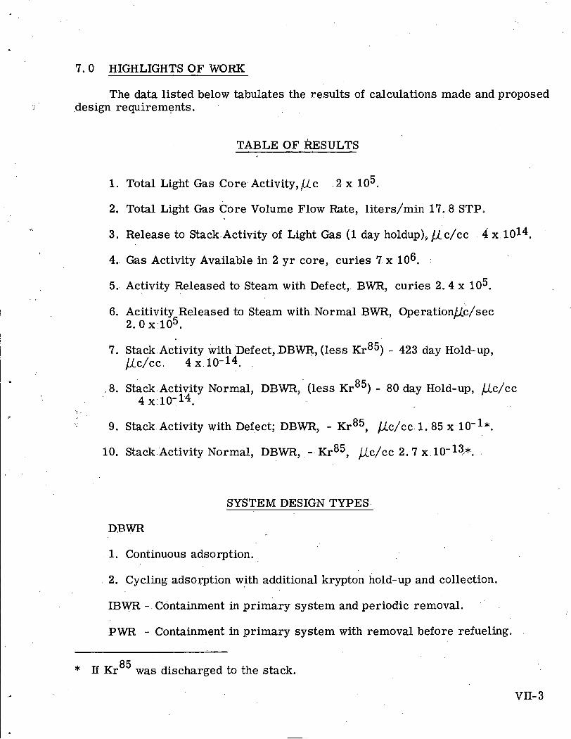
7.0 HIGHLIGHTS OF WORK
The data listed below tabulates the results of calculations made and proposed .design requirements. . .
TABLE OF RESULTS
1. Total Light Gas Core Activity, 11- c 2 x lo3.
2. Total Light Gas Core Volume Flow Rate, liters/min 17.8 STP.
3. Release to Stack.Activity of Light Gas (1 day holdup), /,(.c/cc 4 x 10¹⁴.
4.. Gas Activity Available in 2 y r core, curies 7 x lo6. :
5. Activity Released to Steam with Defect, BWR, curies 2.4 x lo3.
6. Acitivity Released to Steam with. Normal BWR, ~ ~ e r a t i o n ~ i / s e c 2. o ~ ~ 1 0 5 .
7. Stack. Activity with Defect,.DBWR, (less ~ r ~ ~ ) - 423 day Hold-up, PC/CC. 4 x 10-14.
.8. ~ t a c k . ~ c t i v i t ~ Normal, DBWR, (less ~ r ~ ~ ) - 80 dayHold-up, bc/cc 4 ~.10-1,4.
1 .
I - 9. Stack. Activity with Defect; DBWR, - ~ r ~ ~ , l c / c c . 1. 85 x:10-l*.
10. Stack.Activity Normal, DBWR, - ~ r ~ ~ , @/cc 2.7 x .
SYSTEM DESIGN TYPES
DRWR
1. Continuous adsorption.
2. Cycling adsorption with additional krypton hold-up and collection.
IBWR - Containment in primary system and periodic removal.
PWR - Containment in primary system with removal before refueling.
* If ~r~~ was discharged to the stack.
VII- 3

CHAPTER VIII REFUELING SYSTEM DEVELOPMENT (SUBSTASK 4 . 2 . 5 )
G, C. Hauenstein
1.0 STATEMENT AND DISCUSSION OF THE TASK
The PL-3 reactor must be refueled.at regular scheduled intervals through- out the anticipated life of the plant. . The refueling system to be used in this plant must function properly under adverse climatic conditions and refueling time should be kept to a minimum. The remote plant location necessitates that weights be kept as low as possible without sacrificing reliability o r .safety. In order to reduce maintenance, the design of components should s t ress simpl$city without loss of structural integrity.
Spent fuel elements will be shipped by an. air, sea and land route in lead shielded casks from the plant site to reprocessing stations in the U. S. . Air ship- ment of the casks imposes severe limitations on both their size and weight; The optimum shipping cask design is one.in which the total weight of the fuel casks is a minimum. To optimize for a .minimum total weight of fuel casks involves de- termining the shielding requirements and the effects on weight of cooling time and number of elements per cask.
: 2.0 OBJECTIVE OF THE TASK
The object of this task is the study and evaluation of existing refueling systems in order that an optimum arrangement can be evolve? for the PL-3 reactor. ,
'Preliminary shield optimization studies of the spent fuel shipping casks were made with. the following guidelines in mind:
1. The total weight of .spent fuel casks is to be kept to a mini.mum.
2. Casks shall conform to Idaho Chemical Processing.Plant shipping cask requirements.
3. The number of casks shall be adequate to load two complete cores at one time.
4. Casks and fuel shall be protected to prevent damage by an ambient temperature of - 1 0 0 ~ ~ .
VIII- 1
5. Cask will .be designed to proposed .AEC rule f 0, part. 7 2 , . "grotection against radiation in the shipment of irradiated . . fuel elements. l1
6. PL-3 shipping requirements.
3,O DESCRIPTION OF WORK ACCOMPLISHED . .
A literature search of published articEes, including some patents, pertinent .*
to existing refueling and shipping arrangements was conducted. . A study was also made of existing and proposed Alco nuclear reactor plants. To supplement this information, a trip was made to the M. I. To research reactor a t Cambridge,, Massachusetts for a visual study of the refueling system used on their D20 reactor. All information collected was factored into the BWR and PWR concepts to arrive at an optimum design for each basic system. . .Tee work on fuel transfer system development is presented in. APAE Memo-310. * The transfer systems investigated and evaluated a re as follows:
1. Fuel. transfer by flask 2. Fuel transfer by chute 3, Fuel transfer by carriage
Fuel transfer by carriage was ruled out of contention on the grounds of cost, difficulty of maintenance .and complexity. Fuel transfer by flask was considered the most practical method for fuel transfer with the Boiling Water Reactor con- cepts since reactor vessel penetrations posed problems and added to hazard po- tential. Fuel transfer by.spent fuel chute was considered the most practical. ap- proach to spent fuel transfer on the Pressurized Water Reactor concepts, based - on economy, ease of maintenance and reliability determined by past usage. . A typical system utilizing the transfer cask is depicted in Fig. VIU- 1 and a spent fuel chute arrangement .is shown in Fig. VIU-2. A conceptual design of the fuel transfer flask is presented in Dwg. AEL-731. Moaifications will be .made to the systems and components s o that they meet final design requirements.
Three different approaches to fuel storage during cooldown were investi- . .
gated for PL-3 application. These methods are:
1. Fuel. storage in spent fuel. tank. 2. Fuel storage in casks in peripheral shield t d s 3. Fuel storage on skids at remote locati.on
* :Hauen~tein,.. Go C. 9 Pomeroy, Do Lo , "Spent Fuel Transfer Storage and Shipping Study for the PL- 3 Reactor, " Alco Products, Inc.', . APAE Memo- 310, to be issued.
The metnod of remote storage in a small shield tank mounted on a skid - . . was eliminated because cost, maintenance and hazard potential were. excessive. Storage in the shipping casks in the peripheral shield tanks is advantageous be- .
cause the cask supplies the shielding, thereby greatly reducing the plant ship- , -.
ping .weight. The spent fuel tank.would require! approximately 186,000 pounds of shielding in addition to that required for the shipping casks and the entire. reactor plant would probably be lost if this ta&,wereruptured while elements were stored in it,
Shipping casks were investigated on the basi.s of total gross weight per .-
cask and fraction of core contained. Efforts were made to optimize shipping .
casks for each of the four cores proposed. A conceptual design of a shipping cask (Dwg. AEL-735) was made, based on one of these cores.
Shield requirements for four cores were established as part of phase I. The cores considered were (1) P W - 7 x 7 Type 2, (2) PWR - 5 x 5 Type 3, (3) BWR - High enrichment plate type and (4) BWR - Low-enrichment kod type.*
- The shield requirements for sides of the shipping casks were determined by an IBM-650 computer program, These programs considered full cores
, with infinite operating history followed by a ten day decay period. Hand ad- justments were made to the computer output in order to determine side shield
I requirements for partial cores operated for 2 y r with a variety of decay times. Shield requirements for the -shipping cask ends for the selected core were de- termined by a hand calculated model. APAE Memo-310 gives a complete dis- cussion of the calculations and results,
8 - Figure Vm-3 shows the lead shield required to reduce the dose from .a full PWR - 7 x 7 Type 2 core (the reference core) shipping cask to 10 mr/hr at one meter. This curve may be used in determining an optimum shipping time; For example, by delaying shipment from 10 days to 30 days, almost 1 in. of lead may be saved; by waiting f rom30 days to 90 days, about 2 in. of lead may be saved, however, waiting from 90 days to one year will, save less than 1/2 inch.
Figure VIn-4 shows the lead thickness reduction for partial, reference core shipment. . An. .examination of the curve shows that even a large reduction in the number of fuel elements shipped results in only a small. lead thickness reduction. This i.s partially due to the self shielding value of the fuel.. Fuel. elements in the inner rows of the cask a re shielded by the elements in the outer row.
Figure VIII-5 is the dose attenuati.on curve of the side shield at 10 days for each full core. Also shown b. Fig. VUI-6 is the attenuation' curve &%er 2500 h r shutdown for the top and bottom of 15 reference core elements operated for 2 yr. It may be observed that the shielding required for the top and bottom of
. the shipping cask is approximately, 2 in, less than that required for the sides.
Previous reports discussing shielding requirements for shipping.the reference type fuel elements have shown that the lead requirement for the top and bottom' of the shield cask.are. more than o r equal to the sides.
The disparity is due to use of two different models for calculating shield-' ing requirements for the end and side. The ROC code calculation for the side shielding is extremely conservative for the following reasons:
1. The code effectively uses a single energy group for calculation. .
2. The average energy is assumed to be 2 Mev; well above the true ef- , . ... . . -
fective average energy.
3. The analytical model used with ROC code is based upon conservative FI,SSII mptinn a.
4 . 0 CONCLUSIONS
The optimum design of fuel transfer system for the pressurized' water reactor.(PWR) is a fuel'transfer chute arrangement penetrating the vapor con- tainer wall. Vapor containment integrity will bemaintained by use of a seal plug in.the chute. Transfer handling of the core elements will be by hand tools adapted to the final design of the fuel elements and absorbers. This selection of a system was based on previous experience, simplicity of design, e i s e of maintenance and 'relatively low cost.
The optimum design of fuel transfer system for the boiling water reactor .
:(BWR).is one in which the fuel is transferred by shielded flask. The flask-is positioned over the element to be removed by indexing.a vessel shie1d:cover insert, Although more costly, the transfer flask is considered .more desirable, than methods which would require reactor vessel penetration with inherent . . hazard potential.
The optimum fuel storage arrangement is the system utilizing the shipping .
casks in the peripheral storage tanks. The weight saving and relative safety of this arrangement outweighs the minor problem of refined .cask .cooling.
Optimum shipping cask arrangements for the four cores 'studied a re pre- sented .in Table VIII- 1.
The minimum weight shield which woul.d.meet the shipping requirements . .
could be evaluated by judicious experi.mentation, However, the analysis thus farperformed has been sufficient to evaluate the optimum shipping cask size and.decay time before shipment. . An .estimated 15 to 20 percent. shield weight savings might result from the experimentation; however, the present budget al- lows only refinement of the shielding calculations on analytical basis..
vm- 4
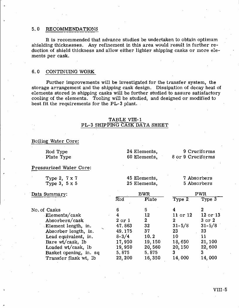
5.0 RECOMMENDATIONS
It is recommended that advance studies be undertaken to obtain optimum shielding thicknesses. Any refinement in this area would result in further. re- duction of shield thickness and allow either lighter shipping casks o r more ele- ments per cask.
6.0 CONTINUING WORK
. . . Further improvements will be investigated for the transfer system, the
storage arrangement and the shipping cask design. Dissipation of decay heat of elements stored in shipping casks will be further studied to assure satisfactory cooling of the elements. Tooling will be studied, and designed o r modified to
. , best fit the requirements for the PL-3 plant.
TABLE VIIZ- 1 PL-3 SHIPPING CASK DATA SHEET
Boiling Water Core:
Rod Type Plate Type
24: Elements, 9 Cruciforms 60 Elements,, ' 8 o r 9 Cruciforms
Pressurized Water Core:
Type.2, 7 x 7 Type 3, 5 x 5
Data Summarv:
No. of Casks : ~lements/cask Absorbers/cask
, Element length, in. Absorber length, in.
\
Lead equivalent, in. Bare wticask, lb Loaded wt/cask, lb Basket opening, in. s q Transfer flask wt, . lb
45 Elements, 7 Absorbers 25 Elements, 5 Absorbers
BWR PWR Rod Plate Type 2. Type 3
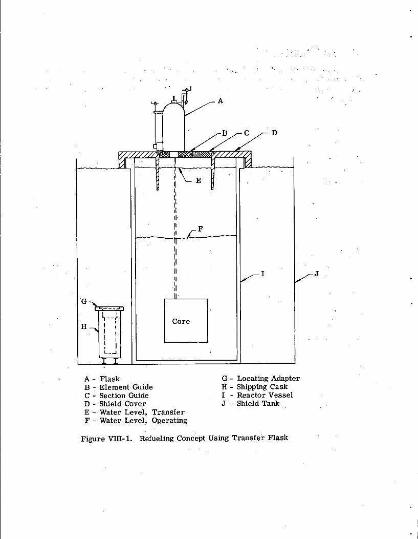
A - Flask G - Locating Adapter B - Element Guide H - Shipping Cask C - Section Guide I - Reactor Vessel D - Shield Cover J - Shield Tank E - Water- Level, Transfer F - Water Level, Operating
Figure VIII- 1. Refueling concept Using Transfer Flask
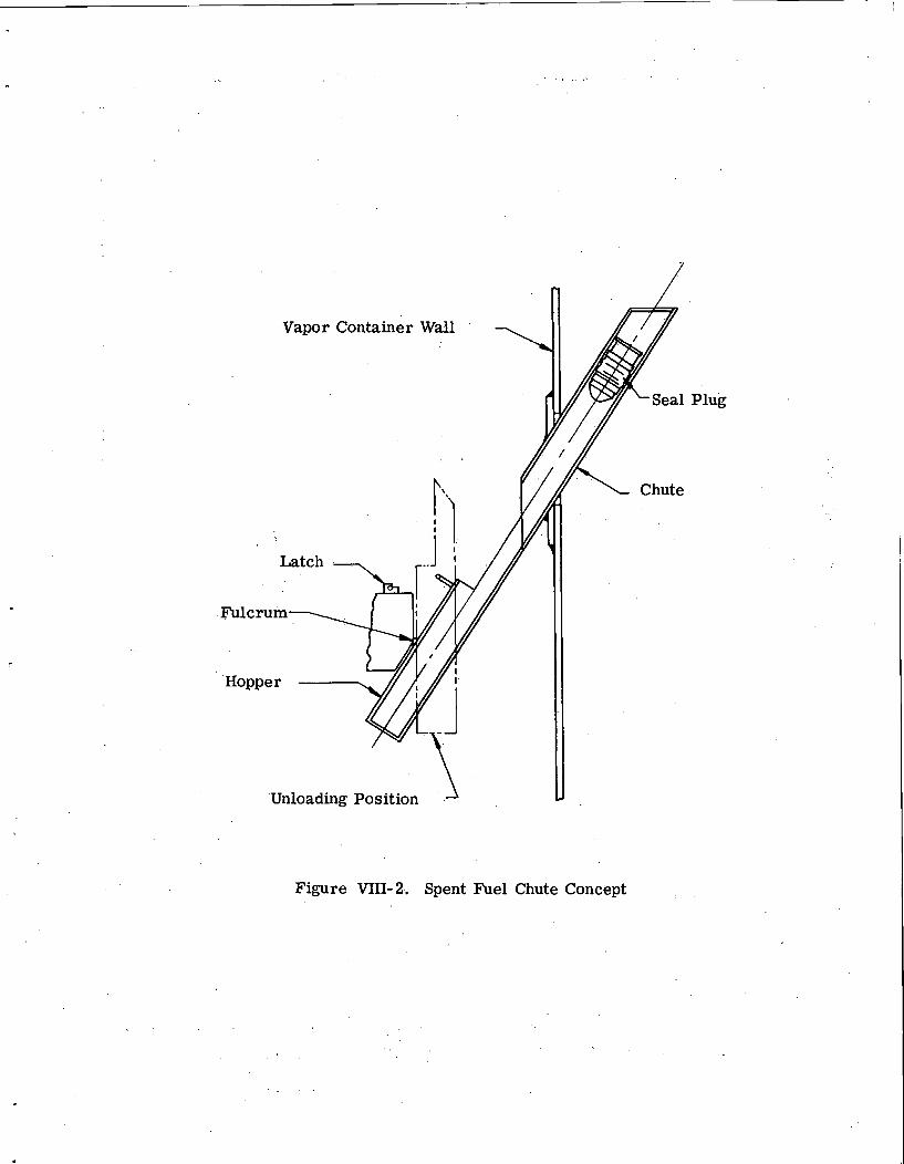
Vapor Container Wall . 1 I I
'Unloading Positioh u
Plug
Figure VnI-2.. Spent Fuel Chute Concept
LEAD REQUIREMENTS FOR ~ O . M R / H R DOSE AT 1 METER - CM
Figure Vm-3. Shielding Requirements for Shipping the Reference Core
Figure 'VIII-4. . Shipping Cask Shield Reduction for Partial ' . Reference Core :
LEAD THICKNESS - CM
Fig.ii-e VIII- 5. Attenuation Curves f o r Reference Core

CHAPTER IX SH-PELD 0P.TIMIZATION (SUBTASK 4.2.7.1)
J. F, Scoles .
1.0 STATEMENT AND DISCUSSION OF TASK
Two basic reactor types were studied in the work involving shield optimi- zation, the boiling water type (BWR) and the pressurized water type (PWR). Among these, geometrical configurations were varied a s well as were dense shielding. materials such a s lead and iron.
It was assumed in these studies that the dense shielding material. was immersed in water. Since basic criteria were minimum weight and shutdown -: dose, it was placed as close as possib1.e to the reactor pressure vessel. Also, the configuration was required to be consistent with .mechanical design and thermal requirements. here fore, three cores were considered:* the highly enriched BWR, .the 5 x 5 core with Type 3 elements, and the 7.'x 7 core with Type 2 elements, the reference core,
.2.O OBJECTIVES OF THE TASK
The radiation level at the surface of the primary shield is restricted to 100 mr/hr at 2 hr after shutdown. The neutron flux at one mile from the PL-3 is restricted to 1 neutron per meter2 per minute. Restrictions a re also im- posed on radiation levels during reactor operation in the plant and camp areas, thus limiting the a i r scatter dose. An outside shield radius of about 7. 5 ft is dictated by the neutron limit. Operating dose limitations du not appear a% this time to be limiting criteria. The basic remaining objective is the shutdown dose rate.
Since minimum shipping weight, ease of construction and reliability a re required, a study of material combinations .which will perform the required shielding is required. This dictated a.parametric'shield optimization study. .
3.0 DESCRIPTION OF WORK ACCOMPLISHED
The calculational method used to obtain required dose rates for the shield- ing study was a machine code for.primary shielding written at. Alco Products and
* ' Humphries, G. E. (Proj, Eng. ), "PL-3 Concept Selection, " Alco Products, Inc. ,. AP Note-408, January 31, 1962. . I
.known as the ROC Code. * The code obtains dose rates for both operating and shutdown reactor conditions. . It differentiates .between.the .dose 'contributed by- the core:as. a source .and that contribution consia~ring neutron r e a c t h s . in. the. materials of the shield a s a source, the shield here being defined as that. portion' of the configuration exterior to the core. Basic input information consists of -
material and .geometrical data as.well as normalized two-group neutron flux values. Output consists of dose rates due to five different source energy groups.
Shielding materials investigated were lead, iron and water. '. The thickness of lead was varied from 0 to 4 in., the iron investigated varied from one 2 in. ring to four 2 in. rings with a 1 in. water annulus between.,each ring.
The reference configuration was taken as one with a 7 x 7; Type 2 PWR employing a stainless steel pressure vessel of 40 in. ID.
A detailed description of all configurations studied will soon be published, .but a table of configurations and reactor conditions is given here in summaryform.
TABLE IX- 1 REACTOR CONFIGURATIONS AND CONDITIONS OF OPERATION
Reactor Pressure Vessel Gamma Operating Type Core Material Shielding Conditions
BWR High .enriched Clad carbon steel 01' Pb shutdown/ 59. 5" ID I. 5" Pb Shutdown
, . 41' Pb Shutdown
PWR 5 x .5 Type 3 Clad carbon steel 0" Pb Shutdown .3'7 steel reflector 1. 5" Pb Shutdown
4l l Shutdown
PWR 7 x 7 Type 2 Clad carbon steel 1,12511 wall 0.25" stainless clad 51. 5" ID
P - i 7 x 7 Type 2 Clad carbon steel
. . P W ' 7 x 7 Type 2 Stainless steel 2. 5" wall 40'"
Shutdown Shutdown Shutdown Ope rating Operating Operating
Shutdown Shutdown Shutdown
Shutdown .
Operating
/ All. shutdown runs made 0.1 day after operation.
* .Rosen, S.S., Oby, P. V., Caton, R. L o , "Preliminary Shield Calculations on the IBM-650 (ROC Codes), l1 Alco Products, Inc. ,. APAE Memo-143, October, 1958.
IX- 2
Neutron flux distributions were normalized to t rue flux values for each reactor. From the neutron distribution, it was possible to obtain flux values thru the shield region to be used as par t of the input to obtain gamma doses due to neutron interactions in the shield materials.
4.0 CONCLUSIONS
Conclusi.ons a r e presented here in the form of two typical piots, Figure IX-1 shows the gamma dose 'rate from the core centerline for the reference con- figuration, Figure IX-2 shows the thickness of lead as a function of shield radius both to meet the neutron flux limit and the gammalshutdown dose rate limit.
5.0 CONTINUING WORK
The development item proposed for continuation of this effort, Pr imary Shielding Development Studies will complete this effort and includes also experi-
:. :. &.. ;<;- ,::; :, :'
mental evaluation of the performance of the primary shielding for configurations .;- ,-.. . , .:7J:::c.~,;.., near those indicated optimum in this study. . ,.;. . . .
IX- 3
DISTANCE FROM CORE CENTERLINE - CM
Figure M-1. Gamma Dose Rate Vs. Distance from Centerline of Core
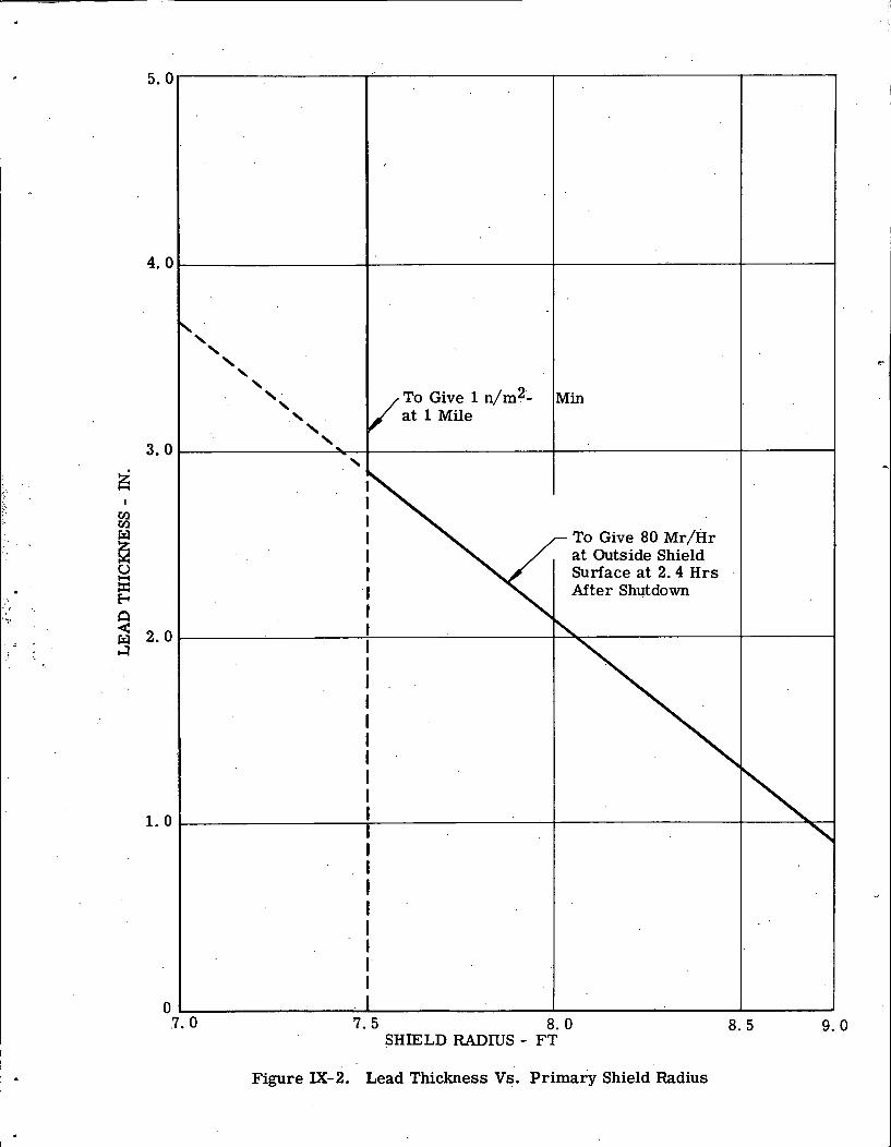
Figure IX-2. Lead Thickness Vs. Primary Shield Radius

CHAPTER X SH-IELDING EFFECTIVENESS (SUBTASK 4.2.7.2) ,
. . Minimum. shipping weight consistent with ease of construction and safety
have dictated that the primary shield be of optimum design. Water is available on-site and need not be shipped in. This suggests its extensive use for shielding. The neutron leakage from the' shield and to a radius of one. mile is also limited.
This optimization problem may be approached by utilization of advanced shielding codes and experimental data. The shielding codes will provide analytical evaluation of the shi.elding. Experimental data available o r specially performed will provide empirical evaluation of the shielding configurations.
2.0 OBJECTIVES OFTASK
Early objectives of this effort were to perform literature surveys to . :.: gather information available on shielding experiments and shielding codes .
which. might be of use in the PL-3 shield design effort. It soon became 'ev.ident that more experimental data a re needed than a re now available. This leads to an additional objective, that of identifying facilities which could provide addi- tional needed. experimentation.
3'. 0 DESCRIPTION OF 'WORK ACCOMPLISHED
A literature survey of colnputer codes was made from published lists, . . Nuclear Science Abstracts and unpublished material. Information sought. for
each code of potential interest included code identification, computer and pro- . .
gramming system, nature of the problem solved, method of soluti.on, restric- - .
tions on.the cooe, options available, machine running time, references, author.(s) and issuing,facility, This information will be published in a. topical report to be .issued shortly. *
* Scoles, J. F., et al, "Studies of Shi.eldi.ng Optimization and..Effectiveness for.PL-3, " Alco Products, Tnc. ,. .APAE Memo-315, .to be issued,
The search for experimental shielding data revealed the following of interest to the PL-3.
ORNL-2518* summarizes-all of the pure water data.for the BSR. These data were taken along an axis from .one face of the BSR in its.poo1. . No inter- vening materials were between the reactor and detectors. Measurements were made to 175 cm from the reactor face for fast neutrons, 765 cm for gamma radiation, and 460 cm for thermal neutrons. The. lack of independance. between gamma radiation and thermal neutrons is evidenced in.these curves. Near. the reactor, captures of thermal neutrons and accompanying production of .2.2 Mev gamma radiation .contributes significantly to the gamma dose (0 to 50 cm). . At' large distances form the reactor, practically all of the thermal neutron flux is due to photoneutron production (beyond 180 cm).
NARF- 55- 85T describes the lead shadow shield experiment performed by Convair. ** In the experiment, lead slah;~ up to 9 in. in thickness were placed between the GTR and detector locations along an axis perpendicular to the reactor face. Fast neutrons and gamma dose measurements were taken to as far a s 175 cm from the reactor face in one configuration with many measurements to 125 cm. No thermal neutron measurements were reported.
Similar:measurements were made. at the BSR with lead slabs in water. . . However, these a r e reported in classified documents, access to which is not
permitted under the contract.
In all of these configurations,. an aluminum structure reactor in an open pool with only lead slabs is used. Since the PL-3 will have a stainless steel structure core,, stainless steel pressure vessel (and perhaps stainless steel thermal shielding), steel shield tank .walls, steel jacketing on the lead shielding,. and high neutron cross 'section vessel insulation, the experimental data available cannot be .expected to provide the empirical shield evaluation needed. With this in mind,. a n effort was made to identify a facility which could mock-up the reactor leakage incident- upoil the shielding and test the. effectiveness of several shield configurations near that to be used on the PL-3.
A literature survey was conducted to locate suitable research reactor facilities with the capabilities to perform an experimental shielding effectiveness program. This survey included university research reactor facilities, AEC- owned-facilities, other government owned and privately operated facilities, and privately owned.and operated facilities. . Out of 35 facilities tabulated during the search, 12 were eliminated because of ilrsufficient reactor power ratings (below 100 kw (t)). The remaining.23 facilities were mailed a letter of inquiry in an
.- . -.
* "~ttenuation in Water of Radiation from the Bulkshielding Reactor, " I Oak: Ridge National Laboratory, ORNL- 251 8, undated. I
I I ** Harris, J. W. , "An Investigation of Shadow Shielding in Water, " Convair, I
NARF- 55- 85T, 1956.
attempt to gather additional information about these facilities and their cap- abilities. . The replies were tabulated with respect to pertinent information: availability and presently scheduled experimentation, adequacy of reactor power .level, equipment available for use during the experimental program, manpower capability and background in similar types of .slab shielding experi- ments and manpower available to perform an experimental program for the PL- 3 shielding effectiveness study. Based on this tabulation, the uniFersity facilities were eliminated because of lack of manpower and, to some extent, .
lack of equipment required to perform the experiment adequa;tely. The pri- vately owned and operated facilities did not lend themselves to a slab shielding experiment. The AEC-owned facilities, in general, had prior experimental commitments and were not available for use for this program; other govern- ment-owned and privately operated facilities, with the exception of General ~ynamics /For t Worth, were not equipped to perform the slab shielding ex- periments proposed for the PL-3. . As a carryover from the ANP program, General Dynamics/Fort Worth had available a slab shielding facility(outside .ASTR Tank Facility), an adequate -number. and size of lead, steel and borated .material slabs for the experimental program, more than adequate dosimetry equipment and a shielding staff with an average of approximately 6 years9 ex- perience per engineer in experimental and theoretical shield design experience. After a visit by two Alco engineers to personally evaluate this facility and the firms capabilities, the decision to select it was made. This selection was
' justified on the basis of available equipment, slabs and capabilities. -.
4.0 CONCLUSIONS REACHED
Sophisticated machine codes a re available for the IBM-7090 and should be obtained for use in PL-3 shielding design analysis. Two such codes a re the G. E. Flexible Monte Carlo Code and the General Dynamics Shield Penetration Code.
No experimental shielding data a r e available sufficiently near the PL-3 corifiguration to permit it to be used as experimental verification,. . An experi- ment is needed if the shield activation (for shutdown dose) and shield neutron capture reactions (for operating gamma dose) a re to be adequately evaluated,
5.0 CONTINUING WORK
As a part of the engineering effort toward shield design, it is planned to .make.operational and use one o r more advanced shielding codes for. PL-3 design analysis.
As a part of the. primary shielding development studies proposed for PL-3 Phase 11 development effort, a comprehensive slab shielding experiment is planned.

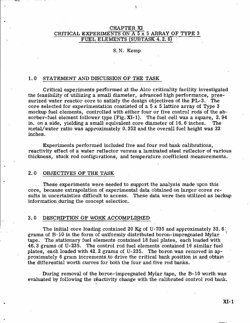
CHAPTER XI CRITICAL. EXPERIMENTS ON A 5 x 5 ARRAY OF TYPE 3
FUEL ELEMENTS (SUBTASK 4.2.8)
S. N. Kemp
1.0 STATEMENT AND DISCUSSION OF THE TASK
Critical experiments .pex;formed at the. Alco criticality facility investigated the feasibility 'of utilizing a small diameter, advanced high performance, pres- surized water reactor core to satisfy the design objectives of thePL-3. The core selected for experimentation consisted of' a 5 x 5 lattice array of Type 3 mockup fuel elements, controlled with .either four o r five control rods of the ab- sorber-fuel element follower type (Fig. XI- 1). The fuel cell was a square, 2.94 in. on a side, yielding a small equivalent core diameter of 16.6 inches. The metal/water ratio was approximately 0.352 and the overall fuel height was 22 inches.
Experiments performed included five and four rod bank calibrations, reactivity effect of a water reflector versus a laminated steel reflector of various thickness, stuck rod configurations, and temperature coefficient measurements.
L
2.0 OBJECTIVES OF THE TASK
These experiments were needed to support the analysis made upon this core, because extrapolation of experimental data obtained on larger' cores re- sults in uncertainties difficult to access. These data were then utilized as backup information during the concept selection.
3.0 DESCRIPTION OF WORK ACCOMPLISHED
The initial core loading contained 20 Kg .of U- 235 and approximately .33. 6 \:,- grams of R- 10 in the form of uniformly distributed boron-impregnated .Mylar . " tape. The stationary fuel elements contained 18 fuel plates, each loaded with 46,3 grams of U-235. The control rod fuel elements contained 16 similar fuel plates, each loaded with 42.2 grams of U-235. The boron was removed in ap- proximately 6 gram incremerats,to drive the critical bank position in and obtain the differential worth curves for both the four and five rod banks.
. During removal of the boron-impregnated .Mylar tape, the B- 10 worth was evaluated by following the &activity change with the calibrated control rod bank.
Immersion heaters and a mixer were used in the reactor tank to increase the moderator temperature from room temperature (680F) to 115O~. The change in reactivity associated with the change in temperature was determined by the change in critical position of calibrated control rod A.
The relative worth of three solid stainless steel.reflectors approximately 1/2, 1, and 2. 5 in. thick with an essentially infinite water reflector were evaluat- ed by observing the change in reactivity for the four and five rod configurations on a calibrated control rod bank.
-Since all four.rod bank measurements were made with the central control rod fully.withdrawn, 'and there exists a difference in U-235 loading between a stationary e-lement and a control rod element. The difference in reactivity was m-easured.for a central stationary .element and the central rod element. The four rod critical.bank position was established with the center control rod fully with- drawn and.a four rod'critical bank position was again establishe+with a stationary element substituted for the Central control rod. The difference in reactivity'at- tributed to the two different calibrated bank positions determined the reactivity difference. '
Stuck rod configurations were evaluated for both the four and five rodded cores. These were made., in order to determine whether these cores would meet the stuck rod criteria set forth for the PL-3.
4.0 CONCLUSIONS REACHED a
~ a s e d on the results of this experimental program, the following con- clusions can be drawn.
1. The cold, clean, critical bank positions and Kex with no burnable poison in the core for the four and five control rod combinations were 4.00 in. / and 4.75 in. , and 26.3 dollars and 26.4 dollars, respectively. Calcula- tions based upon the experimental data indicated an expected core life of approximately 15 MWYR, adequate for the PL-3 design criteria.
2. In the five control rod configuration, with the 9.5 grams of B-10 loading, all control rods exhibited a reversal of worth; i. e. , the rod a t or near
. . the fully withdrawn position had a positive worth over the upper 3 in. of ' travel during insertion, when the remaining four rods were banked. How- -
, . ever, in the.same core with the four rod configuration, there was no' worth reversal indicated.
3. The following relative worths were determined. for three solid stainless -steel.reflectors when comwred to an infinite water reflector: f f 10, 8 cents for a 2. 6 in. thickness; -1 26.0 cents for a f ,'O in. thickness; - 183.2 cents for a 0. 5 in. thickness, This indicates a gain of approxi- mately I. 11 dollars in reactivity if a steel reflector of greater than 2. 5 in. in thickness is used in conjunction with this core,
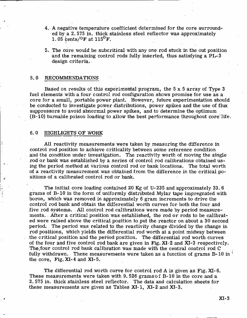
4. A negative temperature coefficient determined for the core surround- ed by a 2.575 in. thick stainless steel reflector was approximately 1.05 kents/oF' at 115'~.
5. The core would ,be subcritical with any one rod stuck.in the out position and the remaining control rods fully inserted, thus satisfying a .PL-.3 design criteria..
I 5.0 RECOMMENDATIONS
Based on results of this experimental program, the 5 x . 5 array of Type 3 fuel elements with a four control rod configuration shows promise for use as a core for a small, portable power plant. However, future experimentation should be conducted to investigate power .distributions, power spikes and the use of flux suppressors to avoid abnormal power spikes, and to determine the optimum (B-,lo) burnable poison loading to allow the best performance throughout core:'life.
6.0 HIGHLIGHTS OF WORK
All reactivity measurements were taken by measuring the difference in control rod position to achieve criticality between some reference condition and the condition under investigation. The reactivity worth of moving the single rod o r bank was established by a ser ies of control rod calibrations obtained us- ing the period method at various control rod o r bank locations. The total worth of a reactivity measurement was obtained from the difference in the critical po- sitions of a calibrated control rod or bank.
The initial core loading contained 20 Kg of U-235 and approximately 33.6 grams of B-10 in the form of uniformly distributed Mylar tape impregnated with boron, which was removed in approximately 6 gram increments to drive the control rod bank and obtain the differential worth curves for both the four and five rod systems, All control rod calibrations were made by period measure- ments. After a critical position was established, the rod o r rods to be calibrat- ed were raised above the critical position to put the reactor on about a 30 second period. The period was related to the reactivity change divided by the change in rod positions, which yields the differential rod worth at a point midway between the critical position and the period position, The differential rod worth curves of the four and five control rod bank are given in Fig. XI-2 and %I-3 respectively. The.four control rod bank calibration was made with the central control rod C fully withdrawn. These measurements were taken as a function of grams B- 10 in ' the core, Fig. XI- 4 and XI- 5.
The differential rod worth curve for control rod .A is given as Fig. XI- 6. These measurements were taken with 9,526 gramso f B- 10 in the core and a 2. 575 in. thick stainless steel reflector. The data'and calculation sheets for these measurements a re given as Tables XI-1, XI-2 and-.XI-3.
XI- 3
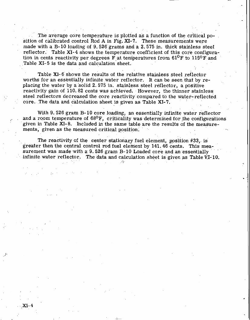
.. . . .
' The average core temperature is plotted as a function of the critical po- sition.of calibrated control ' ~ o d A in Fig. XI-7. These measurements weTe made with a B- 10 loading of 9.526'grams and a 2.575 in. 'thick stainless steel reflector. Table X'I-4 shows the temperature coefficient of this core configura-. .
tion in cents reactivity per degrees Fiat ten&eratures from 61'~. to 1150F and ' ,. .Table XI- 5 is the data .and calculation sheet.
Table XI- 6s'hows the results of the relative stainless steel reflector . .
worths for an esskntially infinite water reflector. It can be seen 'that by re- placing the water by a 'solid 2. 575 in. .stainless steel reflector, a positive reactivity gainof 1-10. 82 cents was achieved. However, the thinner stainless steel..reflectors decreased the core reactivity'.compared to the water-reflected . .
.' core. The daka and calculation sheet.is given as Table XI-7. - . .
With 9.526 gram B-10 core loading, an essentially infinite water reflector I- . and a room temperature of 68O~, criticality was determined for the .configurations
given in Table XI-8. Included in the same table a r e the results of the measure- . . ments; given as the measured c r i t i d p,ositioni , . ' .. . -.,
The reactivity of the center stationary fuel element, p-osition # 3 3 , is' greater then the central control rod fuel element by 141.46 cents. r his mea-
. . . surement was made !with a: 9.526 gram B- 10 Loaded core and an 'essentially
.. . . .infinite:water reflector. The data and cakulation sheet is: given as Table V,I- 10. < . ,
. . . . ' I . . .
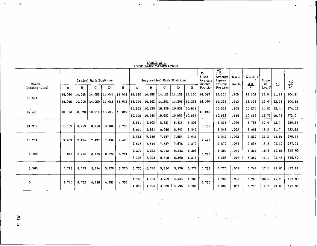
Boron- Loading (gms)
Critical Bank Positions
TABLE XI- 1 5 ROD BANK CALIBRATION
I I x2 I I I I I
Supercritical Bank Positions Critical critical X2-Xi A X of AP A P ,, A B C D E Position Position 7 LogN
14.150 14.159 14.153 14.158 14.160 14.047 14.156 .lo9 14.102 37.0 11.37 104.31
x1 5 Rod Average
5 Rod Average Super-
A X = % = Xl+ Slope
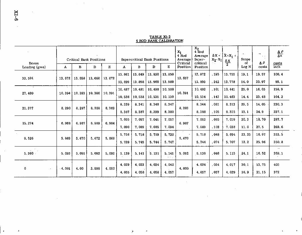
TABLE XI- 2 4 ROD BANK CALIBRATION
.-
hP cents
19.57
23.97
16.05
23.48
14.05
24.9
18.70
27.5
16.97
25.96
16.52
13.75
21.15
x 2 4 Eod Average Su2er- critical Pcasition
12.872
12.899
1-1.492
10.534
8.344
8.388
7.052
7.089
5.118
5.744
5.138
4.034
- A P AX
inch
100.4
99.1
158.9
164.2
230.3
237.1
287.7
269.6
353.5
350.8
359.1
405
372
X1 4 Rod Average Critical Position
13.657
10.391
8.283
6.987
- 5.670
5.092
Boron Loading (gms)
33.584
27.480
21.377
15.274
9.526
5.360
AX =
X2-Xi
. I 9 5
.242
. l o 1
. I43
.061
. I05
.065
. lo2
.048
.074
.046
.034
.057 4.057 0
A
13.672
10.394
8.290
6.988
5.669
5.093
X=x1 + AX - 2
13.755
13.778
10.441
10.463
8.313
8.335
7.019
7.038
5.694
5.707
5.115
4.017
A
13.861
13.899
10.487
10.538
8.339
6.387
7.055
7.090
5.716
5.739
5.139
4.029
- Scope
of Log N
19.1
14.0
25.0
14.4
29.5
13.1
20.3
11.0
23.25
12.2
24.1
30.1
4.029
Critical Bank
B
13.658
10.393
8.287
6.987
5.670
5.091
16.9
Supercritical
B
13.849
13.898
10.481
10.538
8.341
8.387
7.057
7.089
5.718
5.745
5.141
4.033 4.001
4.055
Positions
D
13.668
10.386
8.288
6.989
5.672
5.092
Bank
D
13.850
13.900
10.498
10.531
8.348
8.399
7.041
7.085
5.719
5.744
5.131
4.034 4.00
E
13. 672
10.391
8.269
6.984
5.666
5.092
4.058
Positions
E
13.850
13.900
10.500
10.530
8.347
8.380
7.057
7.094
5.720
5.747
5.141
4.040 3.999
4.058 4.000
4.057
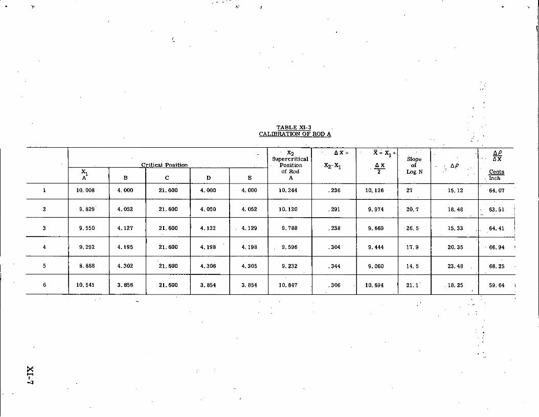
TABLE XI- 3 CALIBRATION O F ROD A
1
2
3
4
5
10.008
9.829
9.550
9.292
8.888
x 2 Supercritical
Pos i t~on of Rod
A
10.244
10.120
9.788
9.596
9.232
1 lo. 541 10.847
B
4.000
4.052
4.127
4.195
4.302
a x =
x2-xl
.236
.291
.238
. 3 04
.344
3.856 .306
Critical Position
C
21.600
21.600
21.600
21.600
21.600
x = x l +
A X - 2
10.126
9.974
9.669
9.444
9.060
21.600 10.694
D
4.000
4.050
4.122
4.198
4.306
Slope of
Log N
27
20.7
26. 5
17.9
14. 5
E
4.000
4.052
4.129
4.198
4.305
3.854 18.25 3.854 59.64 I
AP
15.12
18.48
15.33
20.35
23.48
- AP A X
Cents . Inch
64.07
63.51 1 I I
64.41 1
66.94 I
68.25
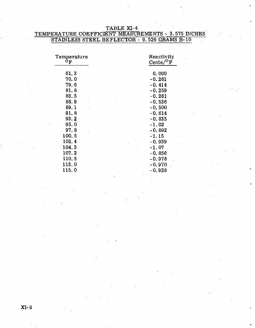
TABLE XI- 4 TEMPERATURE COEFFICENT' MEASUREMENTS - .2.575 INCHES '
.STAINLESS STEEL REFLECTOR - 9.526 GRAMS'B-10 . '
Temperature OF
Reactivity ,
c e n t s / O ~
XI- 8
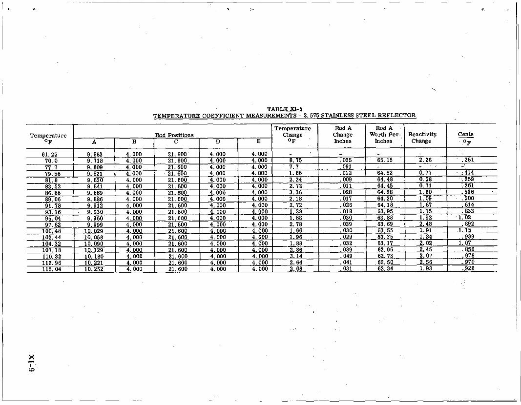
TABLE XI- 5 TEMPERATURE COEFFICIENT MEASUREMENTS - 2 .575 STAINLESS STEEL REFLECTOR
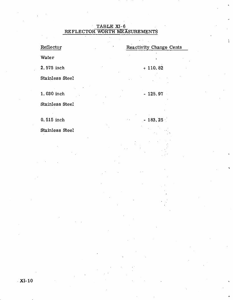
' TABLE XI-6 REFLECTOR WORTH MEASUREMENTS
Reflector ~ i a c t i i i t ~ Change Cents
Water
2. 575 inch
Stainless Steel
1.030 inch
Stainless Steel
0.515 inch
Stainless Steel
XI- 10
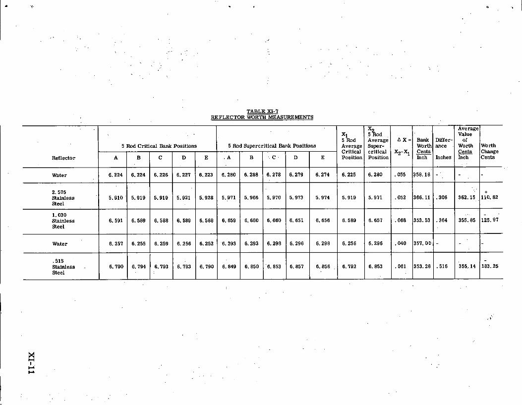
TABLE XI-7 REFLECTOR WORTH MEASUREMENTS
Average Value
of Worth Cents Inch
362.15
355.85
355.14
Reflector
Water
2.575 Stainless Steel
1.030 Stainless Steel
Water
.515 Stainless Steel
Worth Change Cents
+ 110.82
125.97
183.25
X 5 b d Average Super- critical Position
6.280
5.971
6.657
6.296
6.853
A X =
X2-XI
.055
.052
.068
.040
.061
5 Rod Critical Bank Positions
A
6.224
5.910
6.591
6.257
6.790
Bank Worth Cents Inch
358.18
366.11
353.53
357.00
353.28
Xi 5 Rod Average Critical Position
6.225
5.919
6.589
6.256
6.792
5 Rod Supercritical Bank Positions Differ- ance
Inches
-
.306
.364
-
.516
B
6.224
5.919
6.589
6.255
6.794
E
6.274
5.974
6.656
6.298
6.856
. A
6.280
5.971
6.659
6.293
6.849
C
6.226
5.919
6.588
6.259
6.793
B
6.288
5.966
6.660
6.293
6.850
D
6.227
5.921
6.589
6.256
6.793
E
6.223
5.928
6.588
6.252
6.790
C
6.278
5.970
6.660
6.298
6.853
D
6.279
5.973
6.651
6.296
6.857
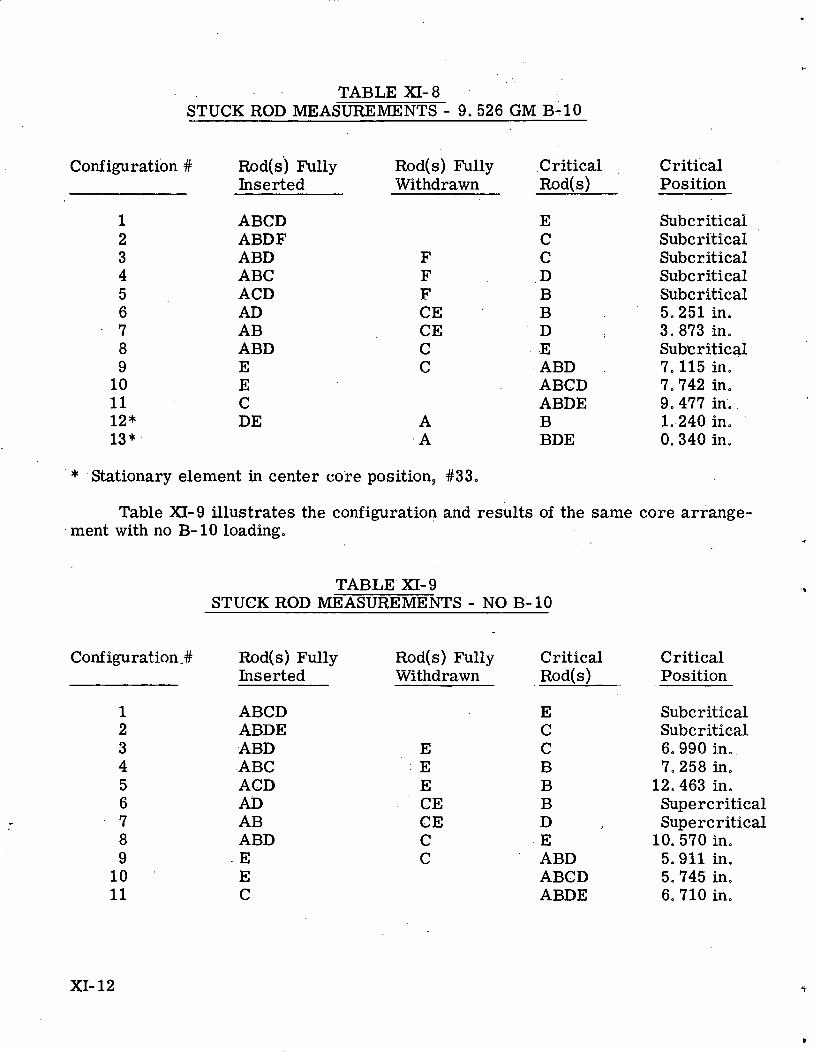
. .
TABLE XI- 8 STUCK ROD MEASUREMENTS - 9.526 GM B-10
Configuration .# ~ o d ( s ) Fully Rod(s) Fully Cri t ica l . Critical Inserted Withdrawn Rod(s) Position
ABCD ABDF ABD ABC ACD AD AB ABD E E C DE
E C C D B B D .E ABD ABCD ABDE B BDE
Subcritical Subcritical Subcritical Subcritical Subcritical 5.251 in. 3.873 in. Subcritical 7. 115 in. 7.742 in, 9.477 in. 1.-240 in. 0.340 in.
* 'Stationary element in center core position, #33.
Table XI-9 illustrates the configuration and results of the same core arrange- ment with no B-10 loading.
TABLE' XI- 9 STUCK ROD MEASUREMENTS - NO B- 10
Configuration. # Rod(s) Fully Rod(s) Fully Critical Critical Inserted Withdrawn R o ~ ( s ) Position
ABCD ABDE ABD ABC ACD AD AB ABD E E C
E C C B B B D E ABD ABCD ABDE
Subcritical Subcritical 6.990 in. 7.258 in.
12.463 in. Supercritical Supercritical
10. 570 in. 5.911 in. 5.745 in. 6. 710 in.
XI- 12
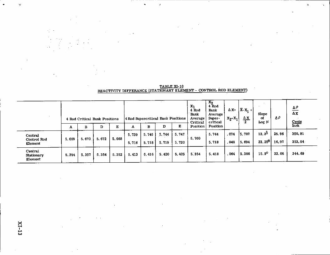
TABLE XI- 1 0 REACTMTY DIFFERANCE (STATIONARY ELEMENT - CONTROL ROD ELEMENT)
4 Rod Critical Bank Positions
Central Control Rod Element
Central Stationary Element
x 1 4 Rod.
'Bank Average
- Critical Position
4 Rod Supercritical Bank Positions
Bank Average Slope AX Super- X2-X1 critical - 2 - Cents Position Inch A
5.669
5.354
E
5.747
5.720
5.425
A
5.739
5.716
5.413
B
5 . 6 7 0 ,
5 .357
B
5.745
5.718'
5.416
D
5 .744
5.719
5.420
D
5.672
5.354
E
5.668
5.352

. . ' Source' .. .
. . . .
Plate Orientation.
Figure XI-1. Positioning.of a 5 x 5 Array of Type III Elements; . . 5'Control Rod Core for PL-3 Mock-up.
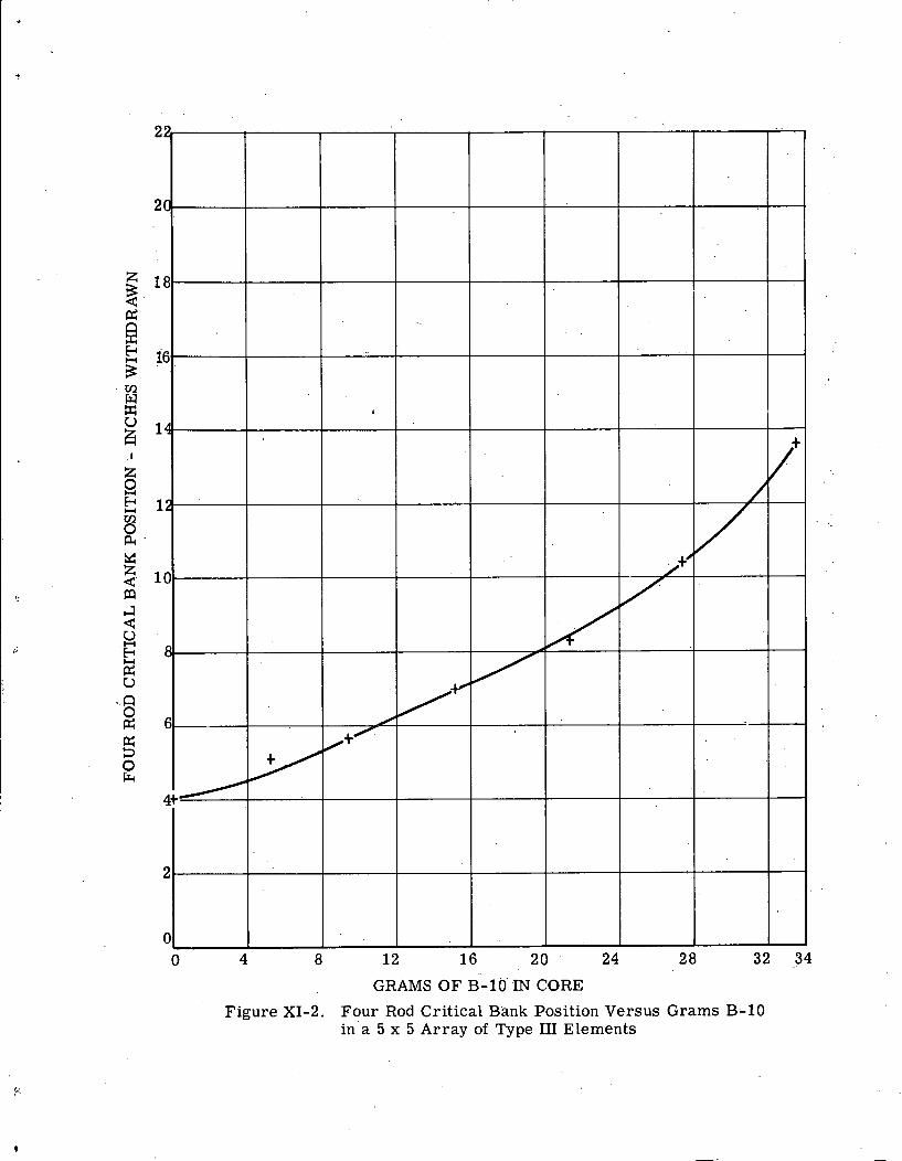
GRAMS OF B-10' 'IN CORE
Figure XI-2. Four Rod Critical Bank Position Versus Grams B-10 in a 5 x 5 Array of Type 111 Elements
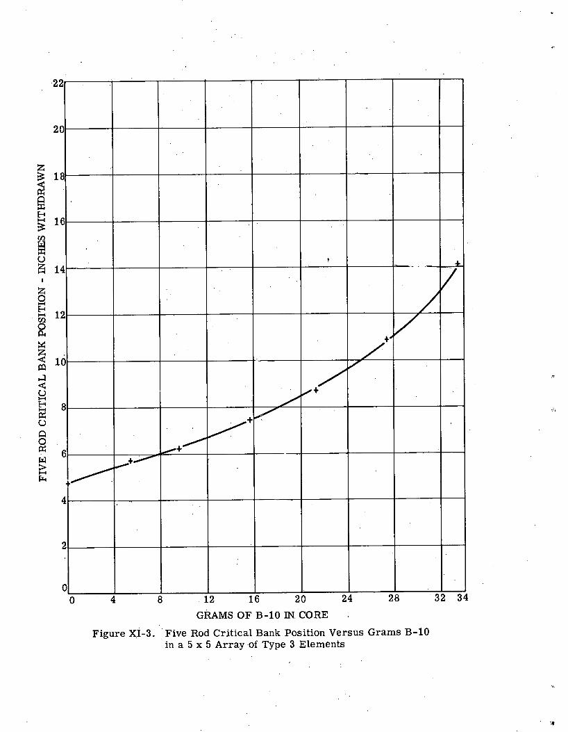
GRAMS OFB-10IN.CORE ' ,
Figure XI-3. Five Rod Critical Bank Position Versus Grams B-10 in a 5 x 5 Array of Type 3 Elements
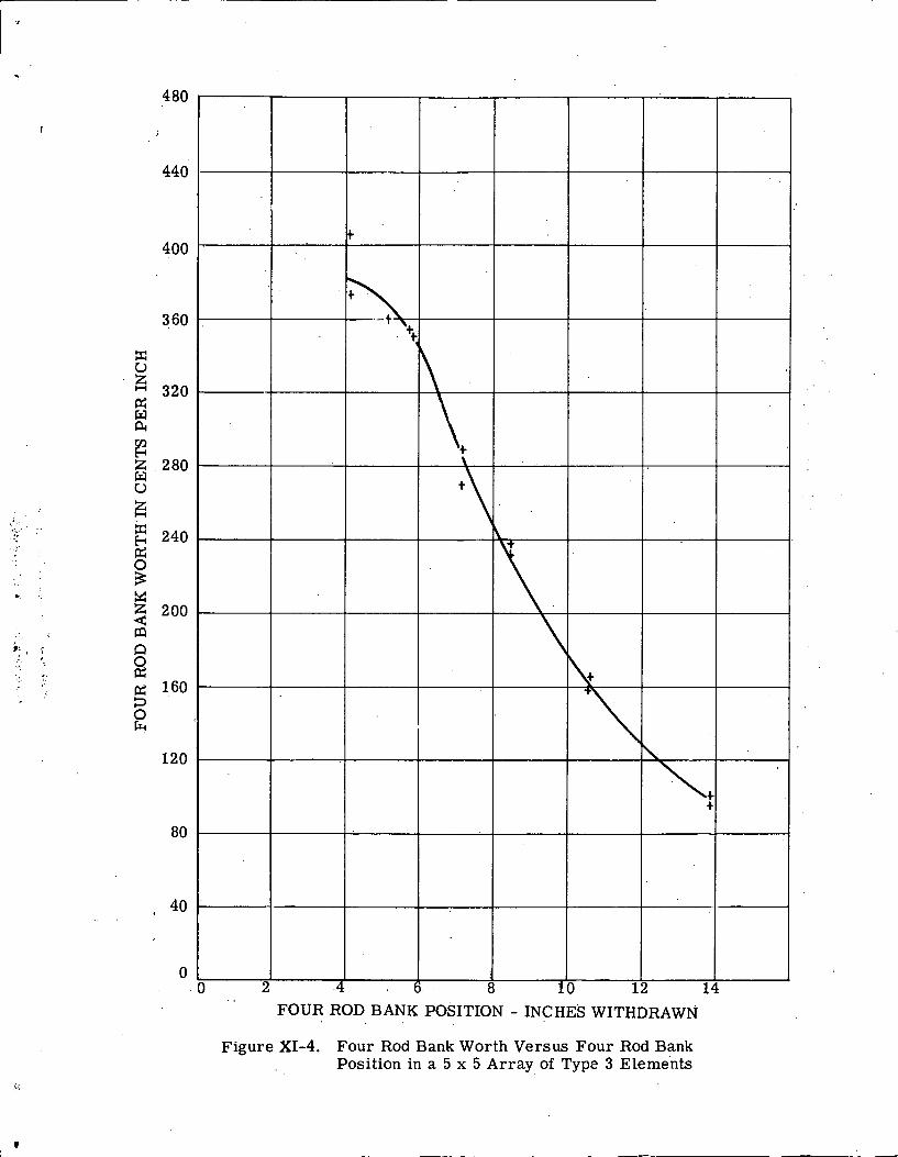
. . FOUR ROD BANK POSITION - INCHES WITHDRAWN
F i g u r e XI-4. F o u r Rod Bank Wor th V e r s u s F o u r Rod Bank Posi t ion in a 5 x 5 A r r a y of Type 3 Elements
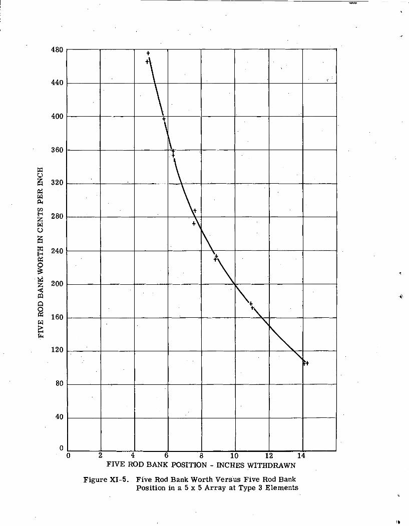
FIVE ROD BANK POSITION - INCHES WITHDRAWN
Figure XI-5. Five Rod Bank Worth Versus Five Rod Bank Position in a 5 x 5 Array at Type 3 Elements
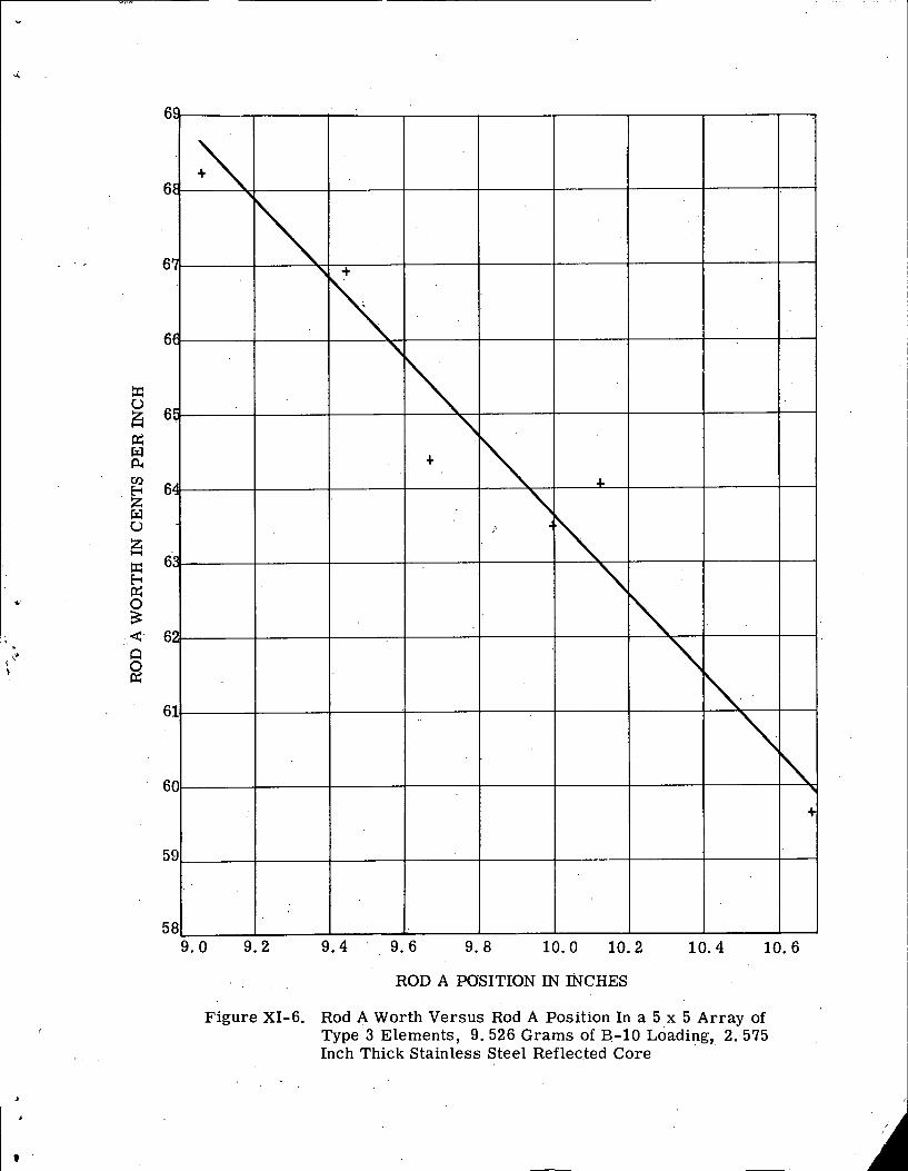
ROD A POSITION IN ~ C H E S
Figure XI-6. Rod A Worth Versus Rod A Position In a 5 x 5 Array of Type 3 Elements, 9.526 Grams of B-10 ~ o a d i n g , 2.- 575 Inch Thick Stainless Steel Reflected Core
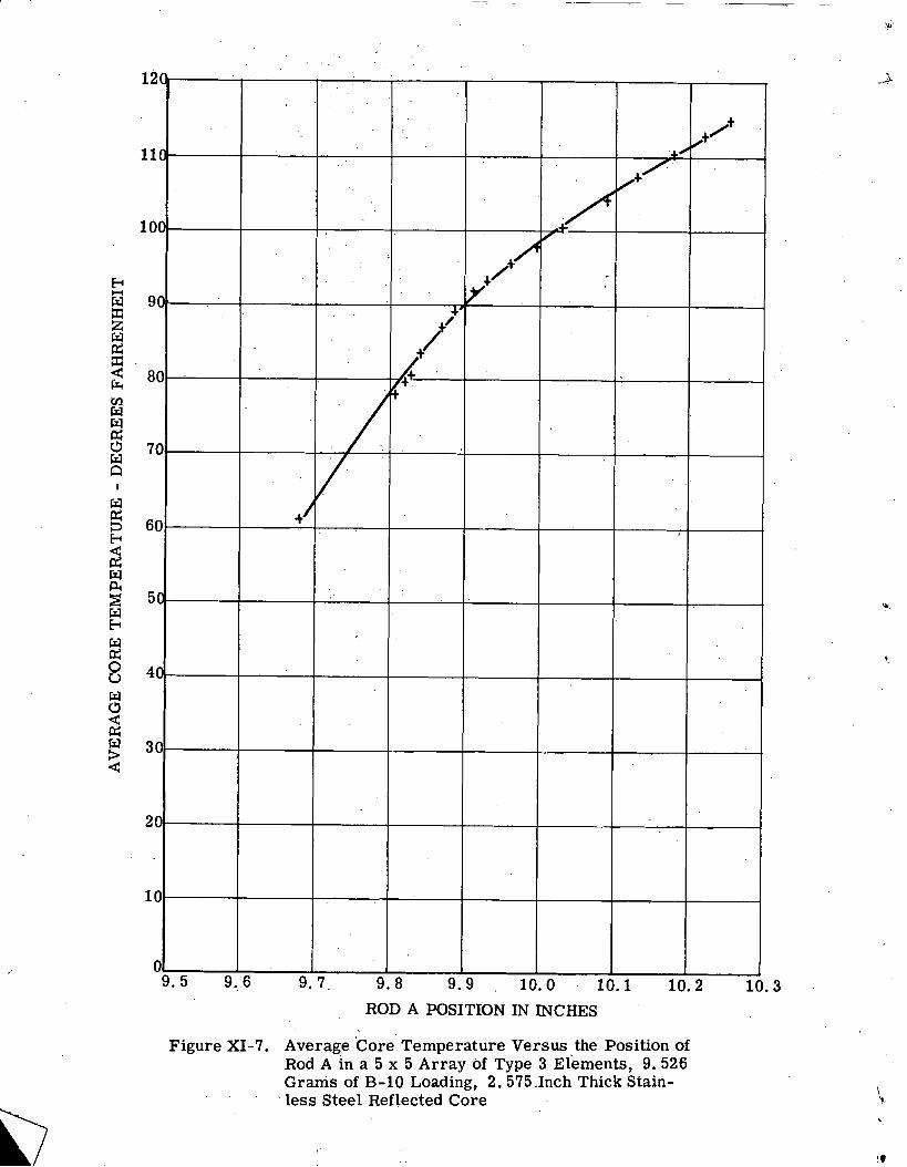
ROD A POSITION IN INCHES
Figure XI-7. Average 'Core Temperature Versus the Position of Rod A in a 5 x 5 Array of Type 3 ~ l e m e n t s , 9 .526 Grams of B-10 Loading, 2 .575 .Inch Thick Stain-
' l e s s Steel Reflected Core