Embed Size (px)
Citation preview

Phase aberration correction by correlationin digital holographic adaptive optics
Changgeng Liu, Xiao Yu, and Myung K. Kim*Digital Holography and Microscopy Laboratory, Department of Physics University of South Florida, Tampa, Florida 33620, USA
*Corresponding author: [email protected]
Received 25 January 2013; revised 27 March 2013; accepted 27 March 2013;posted 27 March 2013 (Doc. ID 184105); published 19 April 2013
We present a phase aberration correction method based on the correlation between the complex full-fieldand guide-star holograms in the context of digital holographic adaptive optics (DHAO). Removal of aglobal quadratic phase term before the correlation operation plays an important role in the correction.Correlation operation can remove the phase aberration at the entrance pupil plane and automaticallyrefocus the corrected optical field. Except for the assumption that most aberrations lie at or close to theentrance pupil, the presentedmethod does not impose any other constraints on the optical systems. Thus,it greatly enhances the flexibility of the optical design for DHAO systems in vision science and micros-copy. Theoretical studies show that the previously proposed Fourier transformDHAO (FTDHAO) is just aspecial case of this general correction method, where the global quadratic phase term and a defocus termdisappear. Hence, this correction method realizes the generalization of FTDHAO into arbitrary DHAOsystems. The effectiveness and robustness of this method are demonstrated by simulations and experi-ments. © 2013 Optical Society of AmericaOCIS codes: (090.1995) Digital holography; (010.1080) Active or adaptive optics; (170.4460)
Ophthalmic optics and devices; (170.0180) Microscopy.http://dx.doi.org/10.1364/AO.52.002940
1. Introduction
Adaptive optics (AO) was initially presented to elimi-nate or alleviate the image distortion due to theatmospheric turbulence in astronomy [1]. Nowadays,AO has become necessary for most of major ground-based telescopes [2,3]. Similar to the ground-basedtelescopes, the human eye also suffers from manymonochromatic aberrations. In 1994, the Shack–Hartmann wavefront sensor used in astronomywas first adopted to measure the ocular aberrationsof the human eyes by Bille’s group [4]. The first AOsystem for vision science was assembled by Lianget al. in 1997 [5]. Using this system, the retinal im-ages at the cellular scale were obtained. Since thattime, AO in vision science has seen rapid growth withmore and more systems being developed [6–11]. AO
has also demonstrated success in microscopy [12].The aberrations induced by variations of refractiveindex through the sample can be reduced throughthe AO system [13]. A typical AO system includesseveral critical hardware pieces: deformable mirror,lenslet array, and a second CCD camera in additionto the camera for imaging. A novel AO system wasrecently proposed to replace these hardware compo-nents with numerical processing for wavefront meas-urement and compensation of aberration through theprinciples of digital holography [14–19].
In the original digital holographic adaptive optics(DHAO) system, the CCD was put in the image planeof the pupil [14]. Although we can obtain a directmeasurement of the wavefront at the pupil, the imag-ing lens other than the eye lens will introduce spheri-cal curvature that has to be removed by additionalmatching lens in the reference beam. Also, the correctguide-star hologram is difficult to obtain. To get afocused image, numerical propagation is necessary.
1559-128X/13/122940-10$15.00/0© 2013 Optical Society of America
2940 APPLIED OPTICS / Vol. 52, No. 12 / 20 April 2013
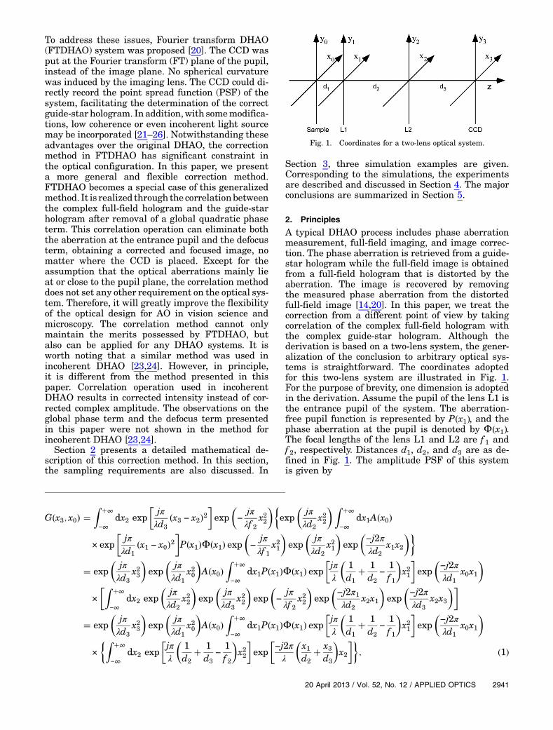
To address these issues, Fourier transform DHAO(FTDHAO) system was proposed [20]. The CCD wasput at the Fourier transform (FT) plane of the pupil,instead of the image plane. No spherical curvaturewas induced by the imaging lens. The CCD could di-rectly record the point spread function (PSF) of thesystem, facilitating the determination of the correctguide-star hologram. In addition,with somemodifica-tions, low coherence or even incoherent light sourcemay be incorporated [21–26]. Notwithstanding theseadvantages over the original DHAO, the correctionmethod in FTDHAO has significant constraint inthe optical configuration. In this paper, we presenta more general and flexible correction method.FTDHAO becomes a special case of this generalizedmethod. It is realized through the correlationbetweenthe complex full-field hologram and the guide-starhologram after removal of a global quadratic phaseterm. This correlation operation can eliminate boththe aberration at the entrance pupil and the defocusterm, obtaining a corrected and focused image, nomatter where the CCD is placed. Except for theassumption that the optical aberrations mainly lieat or close to the pupil plane, the correlation methoddoes not set any other requirement on the optical sys-tem. Therefore, it will greatly improve the flexibilityof the optical design for AO in vision science andmicroscopy. The correlation method cannot onlymaintain the merits possessed by FTDHAO, butalso can be applied for any DHAO systems. It isworth noting that a similar method was used inincoherent DHAO [23,24]. However, in principle,it is different from the method presented in thispaper. Correlation operation used in incoherentDHAO results in corrected intensity instead of cor-rected complex amplitude. The observations on theglobal phase term and the defocus term presentedin this paper were not shown in the method forincoherent DHAO [23,24].
Section 2 presents a detailed mathematical de-scription of this correction method. In this section,the sampling requirements are also discussed. In
Section 3, three simulation examples are given.Corresponding to the simulations, the experimentsare described and discussed in Section 4. The majorconclusions are summarized in Section 5.
2. Principles
A typical DHAO process includes phase aberrationmeasurement, full-field imaging, and image correc-tion. The phase aberration is retrieved from a guide-star hologram while the full-field image is obtainedfrom a full-field hologram that is distorted by theaberration. The image is recovered by removingthe measured phase aberration from the distortedfull-field image [14,20]. In this paper, we treat thecorrection from a different point of view by takingcorrelation of the complex full-field hologram withthe complex guide-star hologram. Although thederivation is based on a two-lens system, the gener-alization of the conclusion to arbitrary optical sys-tems is straightforward. The coordinates adoptedfor this two-lens system are illustrated in Fig. 1.For the purpose of brevity, one dimension is adoptedin the derivation. Assume the pupil of the lens L1 isthe entrance pupil of the system. The aberration-free pupil function is represented by P�x1�, and thephase aberration at the pupil is denoted by Φ�x1�.The focal lengths of the lens L1 and L2 are f 1 andf 2, respectively. Distances d1, d2, and d3 are as de-fined in Fig. 1. The amplitude PSF of this systemis given by
G�x3; x0� �Z �∞
−∞dx2 exp
�jπλd3
�x3 − x2�2�exp
�−
jπλf 2
x22
��exp
�jπλd2
x22
�Z �∞
−∞dx1A�x0�
× exp�jπλd1
�x1 − x0�2�P�x1�Φ�x1� exp
�−
jπλf 1
x21
�exp
�jπλd2
x21
�exp
�−j2πλd2
x1x2
��
� exp�jπλd3
x23
�exp
�jπλd1
x20
�A�x0�
Z �∞
−∞dx1P�x1�Φ�x1� exp
�jπλ
�1d1
� 1d2
−1f 1
�x21
�exp
�−j2πλd1
x0x1
�
×�Z �∞
−∞dx2 exp
�jπλd2
x22
�exp
�jπλd3
x22
�exp
�−
jπλf 2
x22
�exp
�−j2π1λd2
x2x1
�exp
�−j2πλd3
x2x3
��
� exp�jπλd3
x23
�exp
�jπλd1
x20
�A�x0�
Z �∞
−∞dx1P�x1�Φ�x1� exp
�jπλ
�1d1
� 1d2
−1f 1
�x21
�exp
�−j2πλd1
x0x1
�
×�Z �∞
−∞dx2 exp
�jπλ
�1d2
� 1d3
−1f 2
�x22
�exp
�−j2πλ
�x1d2
� x3d3
�x2
��; (1)
Fig. 1. Coordinates for a two-lens optical system.
20 April 2013 / Vol. 52, No. 12 / APPLIED OPTICS 2941

where a prefactor is dropped. A�x0� is the strength ofthe point source at x0 of the sample plane, and λ is thewavelength of the illumination. To simplify Eq. (1),we define β and γ as
β � 11d1� 1
d2− 1
f 1
and γ � 11d2� 1
d3− 1
f 2
: (2)
Then, Eq. (1) can be rewritten as
G�x3; x0� � exp�jπλd3
x23
�exp
�jπλd1
x20
�A�x0�
×Z �∞
−∞dx1P�x1�Φ�x1� exp
�jπλβ
x21
�
× exp�−j2πλd1
x0x1
�
×�Z �∞
−∞dx2 exp
�jπλγ
x22
�
× exp�−j2πλ
�x1d2
� x3d3
�x2
��
� exp�jπλ
�1d3
−γ
d23
�x23
�exp
�jπλd1
x20
�A�x0�
×Z �∞
−∞dx1P�x1�Φ�x1� exp
�jπλ
�1β−
γ
d22
�x21
�
× exp�−j2π
�γx3
λd2d3� x0
λd1
�x1
�: (3)
To further simplify Eq. (3), we define the generalpupil function as
P1�x1� � P�x1�Φ�x1�Φd�x1�; (4)
where
Φd�x1� � exp�jπλ
�1β−
γ
d22
�x21
�; (5)
which is the defocus term of the system. The defocusterm becomes unity if the CCD is at image plane ofthe sample. Now, Eq. (1) can be simplified as
G�x3; x0� � exp�jπλ
�1d3
−γ
d23
�x23
�
× exp�jπλd1
x20
�A�x0�T
�γd1
d2d3x3 � x0
�; (6)
where
T�γd1
d2d3x3 � x0
�� FTfP1�x1�gj
f x� 1λd1
�γd1d2d3
x3�x0
�; (7)
where FT denotes Fourier transform. The complexamplitude of the optical field of an extended objectat the CCD plane is obtained by superposition ofthe amplitude PSF of all the source points, whichis given by
O�x3� � Φq�x3�Z �∞
−∞dx0
× exp�jπλd1
�x20��A�x0�T
�γd1
d2d3x3 � x0
�; (8)
where Φq�x3� is given by
Φq�x3� � exp�jπλ
�1d3
−γ
d23
�x23
�: (9)
This quadratic phase term appears outside the inte-grals in Eqs. (6) and (8). It plays a crucial role in theimage correction, as will be validated in the followingtwo sections. From the guide-star hologram, we canobtain the amplitude PSF given by Eq. (6). RemovingΦq�x3� from the amplitude PSF and setting thesource point at origin, we can obtain a modified am-plitude PSF, as follows:
G1�x3� � A0T�γd1
d2d3x3
�: (10)
Similarly, a modified field of the extended object canbe obtained from the full-field hologram and numeri-cal removal of the quadratic phase term Φq�x3�, asfollows:
O1�x3��Z �∞
−∞dx0 exp
�jπλd1
�x20��A�x0�T
�γd1
d2d3x3�x0
�:
(11)
Correlating this modified field with the modifiedamplitude PSF given by Eq. (10), we have
O1⊗G1�x3��A0
Z �∞
−∞
Z �∞
−∞dαdx0 ×exp
�jπλd1
�x20��A�x0�
×T�γd1
d2d3x3�x0�
γd1
d2d3α
�T�
�γd1
d2d3α
�
�d2d3A0
γd1
Z �∞
−∞
Z �∞
−∞dαdx0
×exp�jπλd1
�x20��A�x0�
×T�γd1
d2d3x3�x0�α
�T��α�; (12)
where⊗ denotes correlation. According to the defini-tion in Eq. (7), we have
2942 APPLIED OPTICS / Vol. 52, No. 12 / 20 April 2013

T�x0 �
γd1
d2d3x3 � α
�
�Z �∞
−∞dηP1�η� exp
�−j2πλd1
η
�x0 �
γd1
d2d3x3 � α
��(13)
and
T��α� �Z �∞
−∞dxP�
1�x� exp�j2πλd1
αx�: (14)
Plugging Eqs. (13) and (14) into Eq. (12), the corre-lation operation results in
O1 ⊗ G1�x3� �d2d3A0
γd1
Z �∞
−∞
Z �∞
−∞dαdx0 exp
�jπλd1
�x20��A�x0�
×�Z �∞
−∞dηP1�η�exp
�−j2πλd1
η
�x0 �
γd1
d2d3x3 � α
��Z �∞
−∞dxP�
1�x� exp�j2πλd1
αx��
� d2d3A0
γd1
Z �∞
−∞dx0 exp
�jπλd1
�x20��A�x0�
×Z �∞
−∞
Z �∞
−∞dxdηP�
1�x�P1�η�exp�−j2πλd1
η
�x0 �
γd1
d2d3x3
���Z �∞
−∞dα exp
�j2πλd1
�x − η�α��
� λd2d3A0
γ
Z �∞
−∞dx0 exp
�jπλd1
x20
�A�x0�
Z �∞
−∞
Z �∞
−∞dxdηP�
1�x�P1�η�exp�−j2πλd1
η
�x0 �
γd1
d2d3x3
��δ�x − η�
� λd2d3A0
γ
Z �∞
−∞dx0 exp
�jπλd1
x20
�A�x0�
Z �∞
−∞dxP�
1�x�P1�x�exp�−j2πλd1
x�x0 �
γd1
d2d3x3
��
� λd2d3A0
γ
Z �∞
−∞dx0 exp
�jπλd1
x20
�A�x0�
Z �∞
−∞dxP�x�exp
�−j2πλd1
x�x0 �
γd1
d2d3x3
��; (15)
From Eq. (15), the correlation operation removesboth the aberration term Φ�x1� and the defocus termΦd�x1�, obtaining a corrected and focused image nomatter where the CCD is put. The magnification ofthis corrected image is given by −�d2d3�∕γd1.Although our derivation is based on a two-lens sys-tem, the conclusion thus rendered can be generalizedto any optical system. The difference lies in the spe-cific expressions for the defocus term Φd�x1� and theglobal quadratic phase term Φq�x3�. According to theconvolution theorem, Eq. (15) can be implemented by
O1 ⊗ G1�x3� � IFTfFTfO1�x3�gFT�fG1�x3�gg; (16)
where IFT denotes the inverse Fourier transform.O�x3� and G�x3� can be obtained through off-axisholography [14–19]. Eliminating the quadratic phaseterm Φq�x3� from O�x3� and G�x3�, we can get O1�x3�and G1�x3�. To achieve the fields O1�x3� and G1�x3�correctly, the sampling requirements have to betaken into account. Taking FT of the amplitudePSF of the source point at origin, we have
FTfG�x3;0�g�A0FT�exp
�jπλ
�1d3
−γ
d23
�x23
�T�γd1
d2d3x3
��
�A0FT�exp
�jπλ
�1d3
−γ
d23
��λd2d3
γ
�2f 2x
��
×⊙FTfFTfP1�x1�g�f x�g
� A0γ
d2
−jλ�d3−γ�
p
×exp�
−jπγ2
λ�d3−γ�d22
x21
�⊙P1�−x1�; (17)
where ⊙ denotes the convolution operation and f x isthe spatial frequency in the horizontal direction,
f x �γ
λd2d3x3: (18)
Expanding Eq. (17), it becomes the spectrum of a fi-nite chirp function. The width of this spectrum canestimated as that of the general pupil function[17,27,28]. Because the sampling requirement forthe one-dimensional case is different from that forthe two-dimensional case, let us now consider thetwo-dimensional case. If the CCD has M ×N squarepixels with side length Δx3, then the sampling spac-ings of the spatial frequency along the horizontal andvertical dimensions are given by
Δf x � Δf y �γ
λd2d3Δx3: (19)
Then the sampling spacings on two dimensions atthe pupil plane are given by [18,19]
20 April 2013 / Vol. 52, No. 12 / APPLIED OPTICS 2943

Δx1 � λd2d3
NγΔx3and Δy1 � λd2d3
MγΔx3: (20)
Assume the diameter of a round pupil is D that isestimated as the width of the image order of the holo-gram, and the width of zero-order of the hologramis twice that of the image order. To recover the opti-cal field at the pupil plane, the pupil size D has tosatisfy [29]
D ≤2
pλd2d3
4γΔx3: (21)
Finally, it is worth mentioning that a special case ofthe correlation method is FTDHAO, where d2 and d3are equal to f 2 [20]. Then Eq. (21) evolves into theexpression for the sampling requirement inFTDHAO.
3. Simulations
In the simulations, the focal lengths, f 1 and f 2, of thelens L1 and L2 are set to be 25 and 200 mm, respec-tively. We set d1, the distance between the sampleand the lens L1, to be 25 mm. The group 4 elements2–5 of USAF1951 resolution target are used to sim-ulate the amplitude of the sample, as shown byFig. 2(a). The field of view is 780 μm × 780 μm. Thepixel pitch is 3.9 μm. A random phase noise ranging
from −π to π simulates the phase distribution of thesample, as illustrated by Fig. 2(b). All the phaseprofiles throughout this paper are displayed inblue-white-red color map that corresponds to �−π; π�.The wavelength of the laser beam is set to be0.633 μm. We present three simulation samples, cor-responding to three different combinations of d2 andd3. In the first case, d2 is set to be 200 mm and d3 tobe 150 mm. Then γ is calculated as 150 mm, accord-ing to Eq. (2), and Φq becomes unity. The CCD is putat a defocus plane of the sample. The defocus termΦd is given by Eq. (5). The simulation results arepresented in Fig. 2. Figure 2(c) is the undistortedbut defocused field at the CCD plane when no aber-ration is added at the pupil plane. The samplingspacing of the spatial frequency in either directionis 0.031 line pairs/mm. For the purpose of compari-son, we propagate it to the image plane. The undis-torted focused image is shown in Fig. 2(d). Figure 2(e)shows the simulated phase aberration Φ addedat the pupil plane, which is given by two sixth-order Zernike polynomials 4π�Z2
6 � Z46� � 4π�15r6
−20r4 � 6r2��cos�2θ� � sin�2θ��. From the full-fieldhologram, we can retrieve the field at the CCD planethat is distorted by this added phase aberrationΦ, asshown in Fig. 2(f). Propagating this distorted field tothe focal plane, we can obtain the focused but de-graded image, as shown by Fig. 2(g). Taking FT ofthe distorted field shown by Fig. 2(f) results in the
Fig. 2. Simulation example where the defocus term Φd exists and the global quadratic phase term Φq is unity. (a),(b) Simulated am-plitude and phase. The phase maps are represented by blue-white-red color map that corresponds to �−π; π�. (c) Optical field at the CCDplane without aberrator in place. (d) Focused image of (c). (e) Simulated phase aberrationΦ. (f) Full-field aberrated hologram at the CCDplane. (g) Focused image of (f). (h) Full-field phase profile at the pupil with aberration. (i) Guide-star hologram, i.e., the amplitude PSF ofthe system. (j) General pupil function that is the FT of (i). (k) Corrected field at the pupil. (l) Corrected image from (k).
2944 APPLIED OPTICS / Vol. 52, No. 12 / 20 April 2013

distorted field at the pupil, which contains both theadded aberration Φ and the defocus term Φd, asshown in Fig. 2(h). The spatial sampling spacing ofthis distorted field is 21 μm. From the guide-starhologram, the amplitude PSF of the system is ob-tained, which is shown in Fig. 2(i). The general pupilfunction that is the FTof the amplitude PSF is shownin Fig. 2(j). The root mean square (RMS) measure-ment error of the phase of the general pupil functionis 0.97 rad that corresponding to about 0.15 wave-lengths. Subtracting Fig. 2(j) from Fig. 2(h), we canget the corrected field at the pupil, which is givenby Fig. 2(k). As described by Eq. (16), the correctedimage can be obtained by taking IFT of Fig. 2(k),which is shown in Fig. 2(l). Compared to the defo-cused and distorted field in Fig. 2(f), the correlationoperation eliminates the aberration and meanwhileautomatically focuses the corrected field.
In the second case, d2 is set to be 300 mm and d3 tobe 200 mm. The defocus term Φd becomes unity,which signifies the CCD is at the image plane ofthe sample. However, in this scheme, the globalquadratic phase term Φq is not unity, which is givenby Eq. (9). The simulation results are shown in Fig. 3.The baseline image, without aberration in place, isshown in Fig. 3(a). Figure 3(b) shows the image dis-torted by the aberration Φ illustrated in Fig. 2(e).Figure 3(c) shows the affected field at the pupil.The amplitude PSF of this system is shown inFig. 3(d). The measured aberration at the pupil isgiven by Fig. 3(e). The RMS measurement error ofthe phase of the general pupil function is 0.91 radthat corresponding to about 0.14 wavelengths.Figure 3(f) illustrates the corrected image that showsremarkable improvement in resolution and quality,compared to the distorted image in Fig. 3(b). In thiscase, removal of the quadratic phase term Φq beforethe correlation operation is found to be of significance
in the correction. The effect of this term on the cor-rected image is shown in Fig. 4. Figure 4(a) shows themeasured aberration at the pupil when Φq is noteliminated before the correlation operation, andFig. 4(c) illustrates the corresponding corrected im-age, which is much degraded compared to Fig. 3(f),that is obtained with Φq removed. If Φq is partiallyremoved, the recovered image becomes better, com-pared to that with Φq untreated. Figure 4(b) showsthe measured aberration at the pupil when Φq is
Fig. 3. Simulation example where Φq exists while Φd is unity. (a) Undistorted optical field at CCD plane. (b) Distorted field at the CCDplane. (c) Distorted field at the pupil. (d) Amplitude PSF of the system. (e) General pupil function. (f) Corrected image.
Fig. 4. Demonstration of the effect of Φq on the corrected image.(a) Measured aberration at the pupil when Φq is not eliminated.(b) Measured aberration at the pupil when Φq is partially elimi-nated. (c) Image corrected by (a). (d) Image corrected by (b).
20 April 2013 / Vol. 52, No. 12 / APPLIED OPTICS 2945

partially eliminated, and Fig. 4(d) shows thecorresponding corrected image.
The third simulation sample demonstrates a gen-eral case where bothΦq andΦd exist. In this case, weset d2 to be 300 mm and d3 to be 150 mm. The sim-ulation results are shown in Fig. 5. Figure 5(a) showsthe distorted full field at the CCD plane that is de-focused and distorted. Note that the quadratic phaseterm Φq has been eliminated. The focused but dis-torted image is shown in Fig. 5(b). The distorted fieldat the pupil is given by Fig. 5(c), which includes theadded aberrationΦ and defocus termΦd. The ampli-tude PSF of this system is shown in Fig. 5(d). Again,the quadratic phase term Φq has been eliminated.
Fig. 5. Simulation example where both Φq and Φd exist. (a) Distorted optical field at the CCD plane. (b) Distorted image. (c) Distortedfield at the pupil. (d) Amplitude PSF of the system. (e) General pupil function. (f) Corrected image.
Fig. 6. Schematic diagram of the experimental apparatus. S,sample; L1–L3, lens; A, aberrator; BS1-4, beam splitters.
Fig. 7. Experimental example where the defocus termΦd exists while the global quadratic phase termΦq is unity. (a) Hologram withoutaberration. (b) Amplitude at the CCD plane. (c) Undistorted field at the pupil. (d) Undistorted image. (e) Distorted hologram. (f) Distortedfield at the CCD plane. (g) Distorted field at the pupil. (h) Distorted image. (i) Guide-star hologram. (j) Amplitude PSF of the system.(k) General pupil function. (l) Corrected image.
2946 APPLIED OPTICS / Vol. 52, No. 12 / 20 April 2013

The FT of this amplitude PSF is given by Fig. 5(e)that includes Φ and Φd. The RMS measurementerror of the phase map represented by Fig. 5(e) is0.88 rad that corresponding to about 0.14 wave-lengths. Removing Fig. 5(e) from Fig. 5(c) and takingIFT, we can get the corrected image shown inFig. 5(f). The resolution is completely recoveredand the defocus is eliminated.
4. Experimental Results and Discussions
The schematic diagram of the experimental setup isillustrated in Fig. 6. The focal length f 1 of the lens L1is 25 mm. S represents the sample plane that is atthe back focal plane of eye lens E. Hence, d1 equals25 mm. The phase aberrator A is close to the pupil ofthe lens L1. The focal length f 2 of L2 is 200 mm. TheCCD has 1024 × 768 pixels with the pixel pitch6.45 μm. In our experiments, He–Ne laser is usedas light source. The sample under test is a positiveUSAF 1951 resolution target with a piece of Teflontape tightly attached behind. The specular reflectionis blocked by the pupil whose size is set to be 5 mm indiameter, and the CCD receives the diffuse scatteredlight from the Teflon tape. A piece of clear brokenglass serves as the phase aberrator. The Lens L3is inserted for full-field illumination. Correspondingto the three simulation cases, we present three exper-imental examples by choosing different values of d2and d3. In the first example, we set d2 to be 200 mmand d3 to be 150 mm, which indicates the CCD is at adefocus plane of the sample. The defocus term Φd iscalculated by Eq. (5). According to Eq. (9), the quad-ratic phase term Φq becomes unity. A set of imagedata is shown in Fig. 7. The field of view on the sam-ple plane is 594 μm× 445 μm. The full-field holo-gram, without the aberrator in place, is shown inFig. 7(a). By the holographic process, the complex op-tical field at the CCD plane can be achieved, which isshown in Fig. 7(b) [15–19]. The sampling spacing ofthe spatial frequency at the CCD plane is 0.037 linepairs/mm in either direction, according to Eq. (19).Taking FT of this field, the full optical field at the
pupil is obtained, as shown in Fig. 7(c). Accordingto Eq. (20), the spatial sampling spacings alongthe horizontal and vertical directions are 27 and35 μm, respectively. For the purpose of comparison,we propagate this defocused field at the CCD planeillustrated by Fig. 7(b) to the image plane, and obtainthe undistorted focused image shown in Fig. 7(d),serving as a baseline. The distorted full-field holo-gram is shown in Fig. 7(e), from which we can getthe distorted and defocused field at the CCD plane,as shown in Fig. 7(f). The distorted full field at thepupil is shown in Fig. 7(g), which contains the addedaberration and the defocus term. Figure 7(h) is thedistorted image. The guide-star hologram is shownin Fig. 7(i), from which we obtain the amplitudePSF of the system that is illustrated by Fig. 7(j).Figure 7(k) shows the general pupil function. Sub-tracting Fig. 7(k) from Fig. 7(g), we get the corrected
Fig. 8. Experimental example whereΦq exists whileΦd takes unity. (a) Undistorted image. (b) Distorted image. (c) Distorted full field atthe pupil. (d) Amplitude PSF of the system. (e) Measured aberration. (f) Corrected image.
Fig. 9. Experimental demonstration of the effect ofΦq on the cor-rected image. (a) Measured aberration at the pupil whenΦq is noteliminated. (b) Measured aberration at the pupil when Φq is par-tially eliminated. (c) Image corrected by (a). (d) Image correctedby (b).
20 April 2013 / Vol. 52, No. 12 / APPLIED OPTICS 2947

field at the pupil. As described by Eq. (16), the cor-rected image can be obtained by taking IFT of thiscorrected field, which is shown in Fig. 7(l). Comparedto the defocused and distorted field in Fig. 7(f), thecorrelation operation eliminates both the aberrationand the defocus term.
In the second example, we set d2 to be 150 mm andd3 to be 200 mm, which indicates the CCD is at theimage plane of the sample. The defocus term Φd dis-appears while the quadratic phase term Φq exists.Figure 8(a) shows the baseline image. The distortedimage is illustrated by Fig. 8(b). Figure 8(c) showsthe distorted full field at the pupil. The amplitudePSF of the system is illustrated by Fig. 8(d).Figure 8(e) is the measured aberration at the pupil.The recovered image is shown in Fig. 8(f). The reso-lution and contrast are almost completely recovered.Note that the quadratic phase term Φq has to be re-moved before the correlation operation. The effect ofthis term on the corrected image is also demon-strated in this example, shown in Fig. 9. Figure 9(a)shows the measured aberration at the pupil whenΦqis not eliminated before the correlation operation,and Fig. 9(c) shows corresponding corrected image,which is rather blurred compared to Fig. 8(f). WhenΦq is partially removed, the recovered image be-comes better. Figure 9(b) shows the measured aber-ration at the pupil when Φq is partially eliminatedand Fig. 9(d) shows the corresponding correctedimage.
For the third experimental sample, d2 is 150 mmand d3 250 mm. This is a general case where bothΦqand Φd exist. The results are shown in Fig. 10.Figure 10(a) shows the distorted field at the CCDplane that is defocused and distorted. Note that thequadratic phase term Φq has been eliminated. Thefocused but distorted image is shown in Fig. 10(b).The distorted full field at the pupil is given byFig. 10(c). The amplitude PSF of this system is illus-trated by Fig. 10(d). Its FT is shown in Fig. 10(e).Subtracting Fig. 10(e) from Fig. 10(c) and takingIFT, we can get the corrected image that is shown
in Fig. 10(f). The resolution is completely recoveredand the defocus is eliminated.
5. Conclusions
In summary, a novel correction method is proposedfor the DHAO system. It is realized through the cor-relation between the complex full-field hologram andcomplex guide-star hologram. By this method, boththe aberration at the pupil and the defocus of the sys-tem can be removed, which means it is not necessaryto further propagate the corrected full field to the im-age plane, wherever the CCD is. It is worth notingthat if the global phase term Φq does exist, it has tobe removed before the correlation operation. Other-wise, the aberrations cannot be correctly compen-sated for. Although our derivation is based on atwo-lens system, the conclusion can be generalizedto any optical system, if the optical aberrations ofthe system mainly lie at or close to the pupil plane.It generalizes the FTDHAO into arbitrary DHAOsystems and provides us a guidance to design newexperimental schemes for applications in AO in oph-thalmology and microscopy. The measurement errorof the phase aberration is due mainly to the deviationof the guide-star spot from the ideal point source. Thesize of the incident beam at the pupil in the first pas-sage for the guide-star hologram is usually set to beabout 2 mm in diameter to minimize the effect of theaberration and generate a sharp guide star. Fromsimulations and experiments, this error does existbut is not severe. Also, coherent noise seems inevi-table if laser is used as the light source. This canbe addressed by use of low coherent light source[21,22,25].
Research reported in this paper was supported bythe National Eye Institute of the National Institutesof Health under Award No. R21EY021876. The con-tent is solely the responsibility of the authors anddoes not necessarily represent the official views ofthe National Institutes of Health.
Fig. 10. Experimental example where both Φq and Φd exist. (a) Distorted optical field at CCD plane. (b) Distorted image. (c) Distortedfield at the pupil. (d) Amplitude PSF of the system. (e) Phase map of the FT of (d). (f) Corrected image.
2948 APPLIED OPTICS / Vol. 52, No. 12 / 20 April 2013

References1. H. W. Babcock, “The possibility of compensating astronomical
seeing,” Publ. Astron. Soc. Pac. 65, 229–236 (1953).2. M. A. van Dam, D. Le Mignant, and B. A. Macintosh, “Perfor-
mance of the Keck observatory adaptive optics system,” Appl.Opt. 43, 5458–5467 (2004).
3. M. Hart, “Recent advances in astronomical adaptive optics,”Appl. Opt. 49, D17–D29 (2010).
4. J. Liang, B. Grimm, S. Goelz, and J. Bille, “Objective measure-ment of wave aberrations of the human eye with the use of aHartmann-Shack wave-front sensor,” J. Opt. Soc. Am. A 11,1949–1957 (1994).
5. J. Liang, D. R. Williams, and D. Miller, “Supernormal visionand high-resolution retinal imaging through adaptive optics,”J. Opt. Soc. Am. A 14, 2884–2892 (1997).
6. A. Roorda, F. Romero-Borja, W. J. Donnelly III, H. Queener,T. J. Herbert, and M. C. W. Campbell, “Adaptive optics scan-ning laser ophthalmoscopy,” Opt. Express 10, 405–412 (2002).
7. K. M. Hampson, “Adaptive optics and vision,” J. Mod. Opt. 55,3425–3467 (2008).
8. I. Iglesias, R. Ragazzoni, Y. Julien, and P. Artal, “Extendedsource pyramid wave-front sensor for the human eye,” Opt.Express 10, 419–428 (2002).
9. N. Doble, G. Yoon, L. Chen, P. Bierden, B. Singer, S. Olivier,and D. R. Williams, “Use of a microelectromechanicalmirror for adaptive optics in the human eye,” Opt. Lett. 27,1537–1539 (2002).
10. S. R. Chamot, C. Dainty, and S. Esposito, “Adaptive optics forophthalmic applications using a pyramid wavefront sensor,”Opt. Express 14, 518–526 (2006).
11. Q. Mu, Z. Cao, D. Li, and L. Xuan, “Liquid crystal based adap-tive optics system to compensate both low and high orderaberrations in a model eye,” Opt. Express 15, 1946–1953(2007).
12. M. J. Booth, D. Debarre, and A. Jesacher, “Adaptive optics forbiomedical microscopy,” Opt. Photonics News 23, 22–29(2012).
13. M. J. Booth, “Adaptive optics in microscopy,” Phil. Trans. R.Soc. A 365, 2829–2843 (2007).
14. C. Liu and M. K. Kim, “Digital holographic adaptive optics forocular imaging: proof of principle,” Opt. Lett. 36, 2710–2712(2011).
15. U. Schnars and W. Jüptner, “Direct recording of holograms bya CCD target and numerical reconstruction,” Appl. Opt. 33,179–181 (1994).
16. E. Cuche, P. Marquet, and C. Depeursinge, “Digital hologra-phy for quantitative phase-contrast imaging,” Opt. Lett. 24,291–293 (1999).
17. C. Liu, D. Wang, and Y. Zhang, “Comparison and verificationof numerical reconstruction methods in digital holography,”Opt. Eng. 48, 1058021 (2009).
18. M. K. Kim, “Principles and techniques of digital holographicmicroscopy,” SPIE Rev. 1, 018005 (2010).
19. M. K. Kim, Digital Holographic Microscopy: Principles, Tech-niques, and Applications (Springer, 2011), pp. 55–93.
20. C. Liu, X. Yu, and M. K. Kim, “Fourier transform digitalholographic adaptive optics imaging system,” Appl. Opt. 51,8449–8454 (2012).
21. F. Dubois, L. Joannes, and J. C. Legros, “Improved three-dimensional imaging with digital holography microscopewith a source of partial spatial coherence,” Appl. Opt. 38,7085–7094 (1999).
22. G. Pedrini and H. J. Tiziani, “Short-coherence digital micros-copy by use of lensless holographic imaging system,” Appl.Opt. 41, 4489–4496 (2002).
23. M. K. Kim, “Adaptive optics by incoherent digital holography,”Opt. Lett. 37, 2694–2696 (2012).
24. M. K. Kim, “Incoherent digital holographic adaptive optics,”Appl. Opt. 52, A117–A130 (2013).
25. F. Dubois and C. Yourassowsky, “Full off-axis red-green-bluedigital holographic microscope with LED illumination,” Opt.Lett. 37, 2190–2192 (2012).
26. R. Kelner and J. Rosen, “Spatially incoherent single channeldigital Fourier holography,” Opt. Lett. 37, 3723–3725 (2012).
27. J. Goodman, Introduction to Fourier Optics, 3rd ed. (Roberts &Company, 2005), pp. 105–107.
28. L. Onural, “Some mathematical properties of the uniformlysampled quadratic phase function and associated issuesin digital Fresnel diffraction simulation,” Opt. Eng. 43,2557–2563 (2004).
29. N. Pavillon, C. S. Seelamantula, J. Kühn, M. Unser, and C.Depeursinge, “Suppression of the zero-order term in off-axisdigital holography through nonlinear filtering,” Appl. Opt.48, H186–H195 (2009).
20 April 2013 / Vol. 52, No. 12 / APPLIED OPTICS 2949