Embed Size (px)
Citation preview
DENNIS V. WALTER JR. | CONSTRUCTION MANAGEMENT
PHASE 2 NEW BUILDING,JOHN TYLER COMMUNITY
COLLEGE Midlothian, VA
FINAL REPORT
Thesis Advisor: Jim Faust
4/7/2010
Image courtesy of Burt Hill
[Special thanks to the Gilbane Project Team, Burt Hill, and John Tyler Community College]
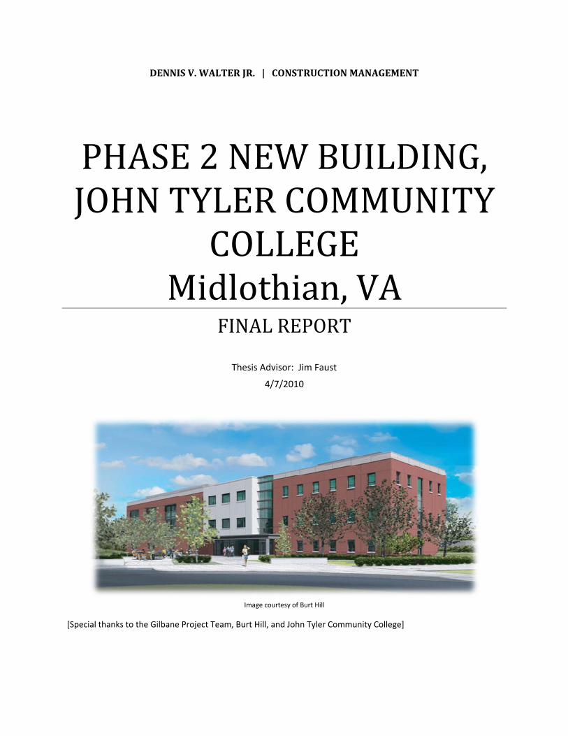
Phase 2 New Building John Tyler Community College, Midlothian Campus
Midlothian, VA
Dennis V. Walter Jr. | Construction Management special thanks to Burt Hill and Gilbane for photos and data
e-Portfolio: http://www.engr.psu.edu/ae/thesis/portfolios/2010/dxw5004/index.html
Owner:
Virginia Community College Systems
CM:
Gilbane
Architect:
Burt Hill
Civil Engineer:
Burgess and Niple
Structural Engineers:
Stroud Pence
MEP Engineers:
H.CYU Engineers
Telecommunications/Audio-Visual/Acoustics Engineers:
Shen Milsom Wilke
Cost Estimating Consultant:
Construction Consultants, Inc.
PROJECT TEAM: Function: Mixed Use Academic Building
Size: 61,000 SF
Height: 3 Stories
Construction Dates: May 2008 – October 2009
Delivery Method: CM @ Risk w/ GMP Contract
LEED® :Pursuing LEED® Silver Certification
PROJECT OVERVIEW:
• (4) 12,500 CFM AHU’s serving Laboratory, Library, Classroom, and others on North End
• (1) 3,750 CFM AHU serving Office/Admin area on South End
• (4) 80 Ton Modular Chillers
• (1) 675 GPM Cooling Tower
• (2) 170 GPM Multi-Zoned Gas Fired Hot Water Storage Heaters
• (2) 1,200 MBH Hydronic Boilers constructed adjacent to Chilled Water Plant
MECHANICAL SYSTEM:
• 968.2 kW Total Connected Load
• 842.3 kW Total Demand Load
• (1) 150 kW Generator
• 277 V Majority of Lighting System
ELECTRICAL SYSTEM:
• Green roof to filter and absorb rainwater, and reduce heat island effect while insulating the building.
• Modular chillers in the mechanical room eliminates the use of oil for the primary cooling equipment in the building
• Recycled content used in building materials such as drywall, fly ash in the concrete, and carpeting
• Natural daylighting sources reduce electrical consumption
• Energy efficient glass and motorized sunshades control solar heat gain, and allow solar shading
• Thermostats in every office to maximize occupants thermal comfort and control
SUSTAINABLE FEATURES:
The exterior of the building is a combination of brick, precast concrete accents, metal panels, aluminum windows and an aluminum framed curtain wall complementing existing buildings on the Midlothian Campus. The layout of the building is designed to accommodate the science department, a library, student lounge, bookstore, and multipurpose room. Science labs on the third floor are the driving force for the building shape. The second floor is the primary entrance of the building from the north, and houses the library. The first floor has an entry on the south to accommodate the newly added south parking lot and contains the bookstore, multipurpose room and the student lounge.
ARCHITECTURE:
STRUCTURAL SYSTEM: Foundation: Reinforced concrete shallow spread footings, Below grade perimeter cantilevered concrete foundation walls, 4” ground floor slab-on-grade
Framing: Elevated slabs (4” lightweight 4000psi concrete over 1 1/2” x 20 gauge VLR composite deck) and roof deck (4” normal weight 4000psi concrete over 1 1/2” x 22 gauge type B composite deck) supported by typical W16 floor beams and W10 columns.
Façade: Masonry veneer backed up by metal stud and curtain wall glazing, CMU (stair and elevator towers), precast concrete and metal paneling w/ steel stud
3
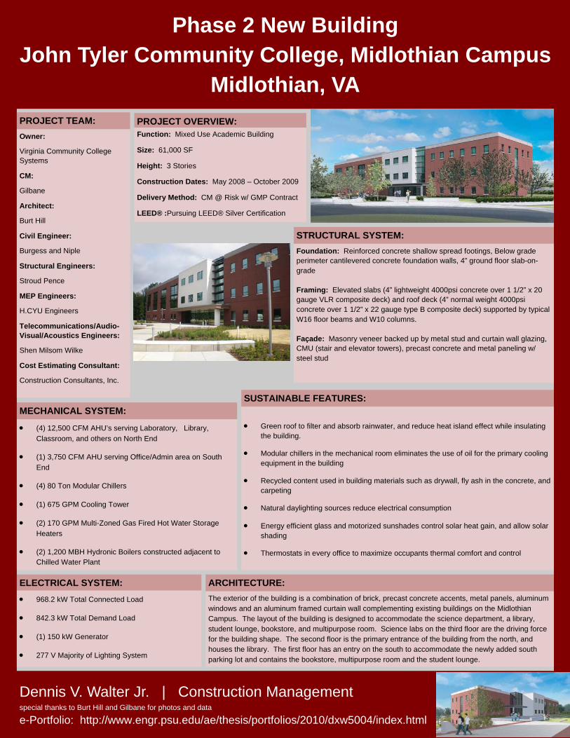
Contents Acknowledgements ....................................................................................................................................... 5
Executive Summary ....................................................................................................................................... 6
Project Overview ........................................................................................................................................... 7
Client & Building Information ................................................................................................................... 7
Project Delivery System ............................................................................................................................ 8
Project Team ............................................................................................................................................. 9
Project Schedule Summary ..................................................................................................................... 10
Detailed Project Schedule ....................................................................................................................... 10
Project Location ...................................................................................................................................... 11
Building Systems Summary ......................................................................................................................... 13
Introduction to Analyses ............................................................................................................................. 18
Constructability Challenges: ................................................................................................................... 18
Analysis I – Brick Facade: ............................................................................................................................ 20
Problem Statement ................................................................................................................................. 20
Background ............................................................................................................................................. 20
Research Method .................................................................................................................................... 21
Goal ......................................................................................................................................................... 21
Analysis ................................................................................................................................................... 21
Quality Control Issues ............................................................................................................................. 27
Schedule .................................................................................................................................................. 27
Cost ......................................................................................................................................................... 29
Conclusions and Recommendations ....................................................................................................... 30
Analysis II – Roofing System: ....................................................................................................................... 31
Problem Statement ................................................................................................................................. 31
Background ............................................................................................................................................. 31
Research Method .................................................................................................................................... 31
Goal ......................................................................................................................................................... 32
Master of Architectural Engineering Requirements ............................................................................... 32
Analysis ................................................................................................................................................... 32
Schedule .................................................................................................................................................. 36
Cost ......................................................................................................................................................... 37
4
Conclusions and Recommendations ....................................................................................................... 37
Analysis III – Electrical System: ................................................................................................................... 39
Problem Statement ................................................................................................................................. 39
Background ............................................................................................................................................. 39
Research Method .................................................................................................................................... 39
Goal ......................................................................................................................................................... 40
Analysis ................................................................................................................................................... 40
Quality Control Issues ............................................................................................................................. 43
Best Practices .......................................................................................................................................... 43
Conclusions and Recommendations ....................................................................................................... 44
Summary and Conclusions .......................................................................................................................... 45
References .................................................................................................................................................. 47
Appendix A: Project Schedule Summary ..................................................................................................... 49
Appendix B: Detailed Project Schedule ...................................................................................................... 51
Appendix C: Precast Panel Takeoffs ............................................................................................................ 57
Appendix D: Panel Sizes Summary .............................................................................................................. 61
Appendix E: Detailed Project Schedule – Alternative Exterior Façade ....................................................... 63
Appendix F: Detailed Exterior Façade Systems Cost Comparison .............................................................. 69
Appendix G: TPO “Cool” Roof Thermal Properties ..................................................................................... 71
Appendix H: Detailed Roofing Systems Cost Comparison .......................................................................... 73
5
Acknowledgements I would like to thank the following people for their assistance in allowing this thesis to be completed on the Phase 2 New Science Building at the John Tyler Community College Midlothian Campus:
John Tyler Community College:
Leigh LaClair
William Taylor
Gilbane Building Company:
Drew Micco
Nick Ivey
Brett Thompson
Burt Hill:
Damon Sheppard
Capital Masonry:
Wayne Young
International Roofing:
Gary Morrison
Construction Management Thesis Consultant:
Jim Faust
ISEC, Inc.
Matthew Hiestand
Jason Hunter
Penn State AE Faculty & Colleagues
Family and Friends
6
Executive Summary This final thesis report is a result of several analysis conducted over the course of the Spring 2010 semester‐long Architectural Engineering capstone project. The subject of analysis is the Phase 2 New Building at the John Tyler Community College’s Midlothian Campus in Midlothian, VA just outside Richmond. The Phase 2 New Building is the campuses’ most recent and headline project under the Virginia Community College System. This building is part of a new green initiative taken on by the John Tyler Community College and is the first project to be LEED® rated for the Virginia Community College System.
This final report contains three analyses that investigate areas of specific quality and constructability issues associated with this project. The first analysis investigates a high‐quality alternative exterior façade taking the place of a hand‐laid masonry brick wall and the cost and schedule benefits that occur. The second analysis looks into an alternative roofing system to determine whether a more cost‐effective and high‐quality system can replace the green roof system and inverted roof membrane assembly while comparing the quality and LEED® benefits of each. The third analysis incorporates research into building transformers and the steps in properly and sizing a safely operating transformer.
It has been determined that, through the first analysis, an alternative architectural precast panel system in lieu of the hand‐laid masonry brick wall can provide similar aesthetic quality based on the proper selection of thin brick cast into the concrete panels. Also, it compares similarly in costs, resulting in a $15,883 reduction in upfront expenditure. Additionally, the building enclosure schedule can be reduced by 16 days and site congestion can be minimized.
The second analysis, dealing with an alternative roofing system, determined that a single‐ply thermoplastic TPO “cool” roofing system can offer unique benefits to the owner, but may not stack up in comparison with the originally designed green roof and IRMA systems in terms of energy efficiency and potential LEED® credits. While the single‐ply TPO “cool” roof investigated in this analysis is estimated to save $269,300 in upfront costs, the system does not offer the same long‐term energy efficiency benefits as the green roof, resulting in an estimated 37% increase in summer heat gains and 65% increase in winter heat loss through the compared roof systems. Also, the green roof potentially offers 4 to 10 additional LEED® credits beyond what the alternative “cool” roofing system could.
Finally, the third analysis dealt with research into the buildings electrical system transformer. This analysis is mainly research into the building transformer and the process for properly sizing the transformer device to safely handle the predicted building loads. This process involves communication between both the electrical design engineer and the engineer with the electrical power company providing the equipment. Through research, quality issues and best practices were determined for the design, installation and maintenance of the building transformer.
7
Project Overview
Client & Building Information The 61,000‐square‐foot building is the first project in the Virginia Community College System to be registered under the Leadership in Energy and Environmental Design (LEED®) Green Building Rating System. To become LEED® certified, a project must earn credits in key areas that promote human and environmental health, including sustainable site design, water savings, energy efficiency, materials selection, and indoor environmental quality.
The new building, which houses science laboratories, classrooms, an expanded library, a multi‐purpose room, and additional commons space for faculty and students, was built to help the College continue to meet rapidly increasing demand for classes at the College. John Tyler Community College’s Midlothian Campus, built in 2000, grew so quickly that the campus reached full capacity in 2005. In 2006, the Virginia General Assembly approved construction of the much‐needed second academic building. Master plans for the Midlothian Campus eventually call for a bell tower, amphitheatre and possibly sports fields.
The Virginia Community College System had agreed on an original $18.5 million guaranteed maximum price (GMP) contract that was within their budget, and contained an allowance for owner’s contingency that would cover possible changes. In previous Midlothian Campus projects, the Virginia Community College System and the John Tyler Community College were not satisfied with the existing structures built; one of the existing buildings had ended in a legal case against a previous contractor due to leaky building enclosures and also had excessive and bothersome mechanical equipment noise and vibrations. The expected quality of this new building is a water tight enclosure, reduced mechanical noises and vibrations and a project that meets LEED® requirements. There safety requirements by the owner were keeping the students, faculty and public safe during construction, and Gilbane’s extensive safety plan was adopted for this project to add additional safety measures.
Since this building is an educational facility on a college campus, there was a requirement set by the owner that substantial completion be prior to the start of a new fall semester. The sequencing of the building had to be planned in order to fulfill the occupancy requirement of a one month owner move‐in prior to the new semester. In order for Gilbane to construct a building that the owner is satisfied with, they must produce a quality building with fully a functional, watertight exterior façade, achieve a LEED® rated status, have very minimal mechanical equipment noises and vibrations, and perform within their budgeted plans.
8
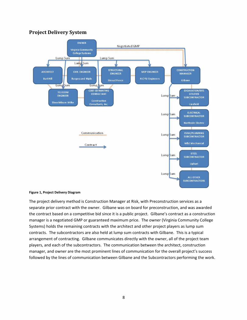
Project Delivery System
Figure 1, Project Delivery Diagram
The project delivery method is Construction Manager at Risk, with Preconstruction services as a separate prior contract with the owner. Gilbane was on board for preconstruction, and was awarded the contract based on a competitive bid since it is a public project. Gilbane’s contract as a construction manager is a negotiated GMP or guaranteed maximum price. The owner (Virginia Community College Systems) holds the remaining contracts with the architect and other project players as lump sum contracts. The subcontractors are also held at lump sum contracts with Gilbane. This is a typical arrangement of contracting. Gilbane communicates directly with the owner, all of the project team players, and each of the subcontractors. The communication between the architect, construction manager, and owner are the most prominent lines of communication for the overall project’s success followed by the lines of communication between Gilbane and the Subcontractors performing the work.
9
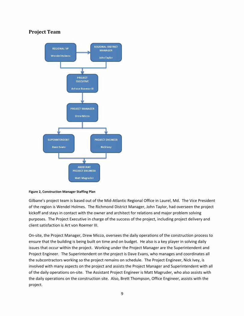
Project Team
Figure 2, Construction Manager Staffing Plan
Gilbane’s project team is based out of the Mid‐Atlantic Regional Office in Laurel, Md. The Vice President of the region is Wendel Holmes. The Richmond District Manager, John Taylor, had overseen the project kickoff and stays in contact with the owner and architect for relations and major problem solving purposes. The Project Executive in charge of the success of the project, including project delivery and client satisfaction is Art von Roemer III.
On‐site, the Project Manager, Drew Micco, oversees the daily operations of the construction process to ensure that the building is being built on time and on budget. He also is a key player in solving daily issues that occur within the project. Working under the Project Manager are the Superintendent and Project Engineer. The Superintendent on the project is Dave Evans, who manages and coordinates all the subcontractors working so the project remains on schedule. The Project Engineer, Nick Ivey, is involved with many aspects on the project and assists the Project Manager and Superintendent with all of the daily operations on‐site. The Assistant Project Engineer is Matt Magruder, who also assists with the daily operations on the construction site. Also, Brett Thompson, Office Engineer, assists with the project.
10
Project Schedule Summary (Actual schedule evaluation is based on a detailed schedule provided by Gilbane. The dates have been slightly altered and simplified for the convenience of this report.)
The design for the Phase 2 New Building at John Tyler Community College began late in 2007 through 2008. Gilbane was brought on board early during the design phase to assist with preconstruction services. The preconstruction activities included assisting the A/E and Owner during the design to keep the building within budget. Gilbane provided the estimating and constructability reviews and value analysis. After a design was finished, the project was put out to bid to multiple trade contractors in bid packages and Gilbane was awarded the contract for construction manager. Construction began shortly after with the Notice to Proceed issued early in 2008. The final completion and handover of the Phase 2 New Building was set for October 30, 2009.
See Appendix A: Project Schedule Summary.
Detailed Project Schedule (Actual schedule evaluation is based on a detailed schedule provided by Gilbane. The dates have been slightly altered and simplified for the convenience of this report.)
Construction sequencing is broken up by floors and areas of the building. After site clearing and excavation, work on the foundation and superstructure began. This is including all piers, footings, grade beams, below grade foundation walls, and slab on grade. MEP work begins rough‐in and placement after excavation is completed and continues through the majority of the construction phase. Once the foundation activities were wrapping up, the structural steel and CMU walls began. Steel was able to be fabricated and delivered while the substructure was still being put into place to allow for a smooth transition of work. The masonry and curtain wall façade followed until the building was fully enclosed by the envelope and roofing system. The building skin was broken into sections based on column lines and exterior wall systems. Then, interior trades could begin installations starting with the ground level and working up to floor 3. Once the project was wrapping up with furnishings, equipment and was fully enclosed, the testing, balancing, and commissioning of the building systems could take place. The building had to be substantially complete to provide the owner with a month of move‐in activities before the first day of classes on August 24, 2009.
Please see Appendix B: Original Detailed Project Schedule.
11
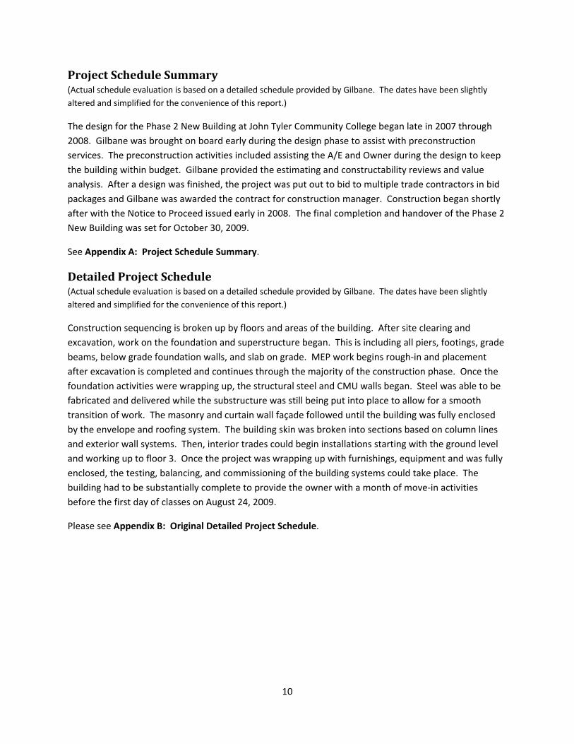
Project Location The 117.2 acre site is located west of Charter Colony Parkway within the Midlothian Campus of John Tyler Community College in Chesterfield County, Midlothian, Virginia.
Figure 3, Site Location; Image extracted from ADC Street Map Book, Chesterfield County, Virginia.
The site includes several existing campus buildings and two small tennis courts directly to the north of the building location. The tennis courts will be relocated before construction begins, while the surrounding existing buildings remain open. The relocation of utilities is minimal for this project, because of the presence of existing campus buildings.
Because of the topography of the site and access to existing buildings, the Phase 2 New Building will have entrances to the south on the first floor and to the north on the second floor. The existing plaza connecting the two existing buildings to the east will remain, but will be extended to the west to provide access to the new building.
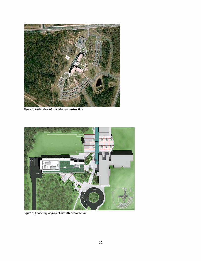
Only the central portion of the site was developed prior to construction. The campus property was occupied by three buildings connected by nearby access roads, parking lots, and lawn areas. Other parts of the site are heavily wooded and undeveloped. The southwest edge of the site is bordered by a wide power line right‐of‐way. The north and eastern property boundaries are Woolridge Road and Charter Colony Parkway, respectively.
12
Figure 4, Aerial view of site prior to construction
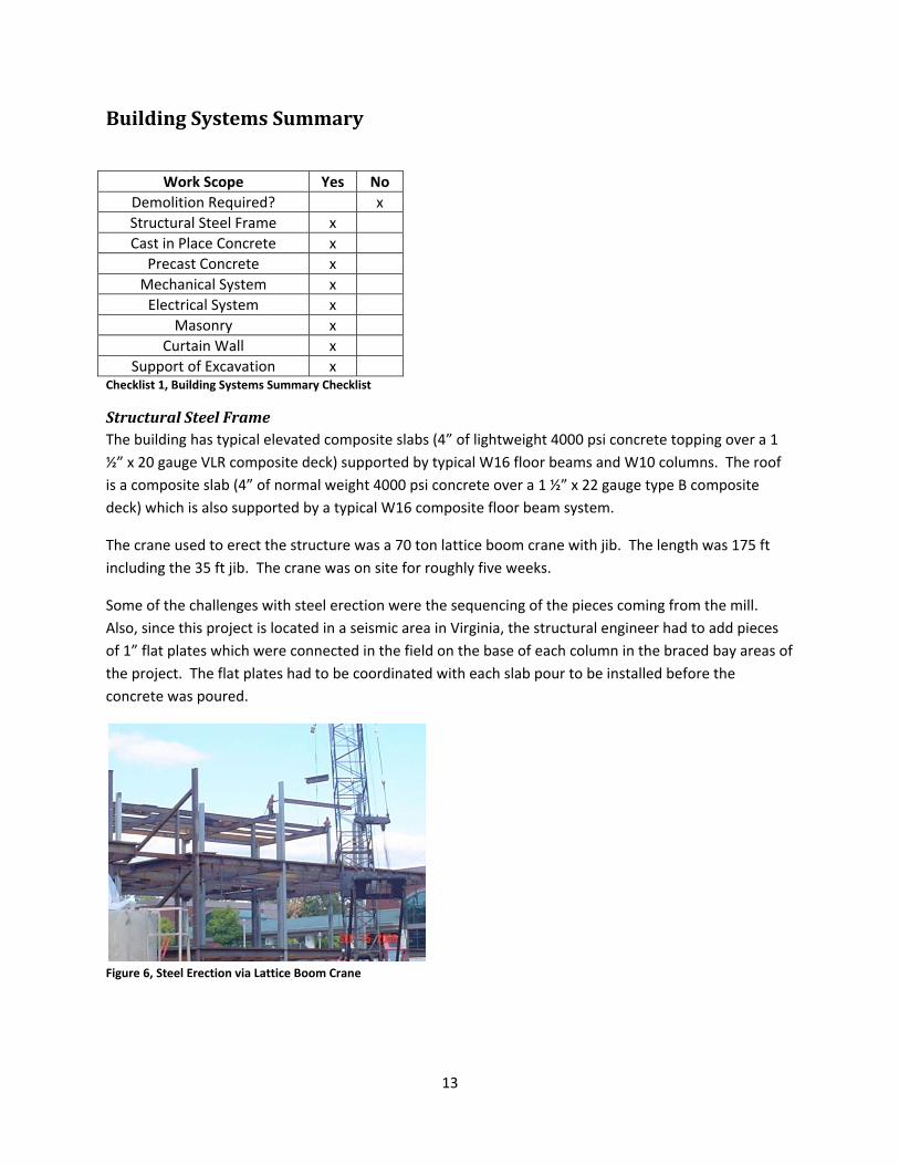
Figure 5, Rendering of project site after completion
13
Building Systems Summary
Work Scope Yes No Demolition Required? x Structural Steel Frame x Cast in Place Concrete x
Precast Concrete x Mechanical System x Electrical System x
Masonry x Curtain Wall x
Support of Excavation x Checklist 1, Building Systems Summary Checklist
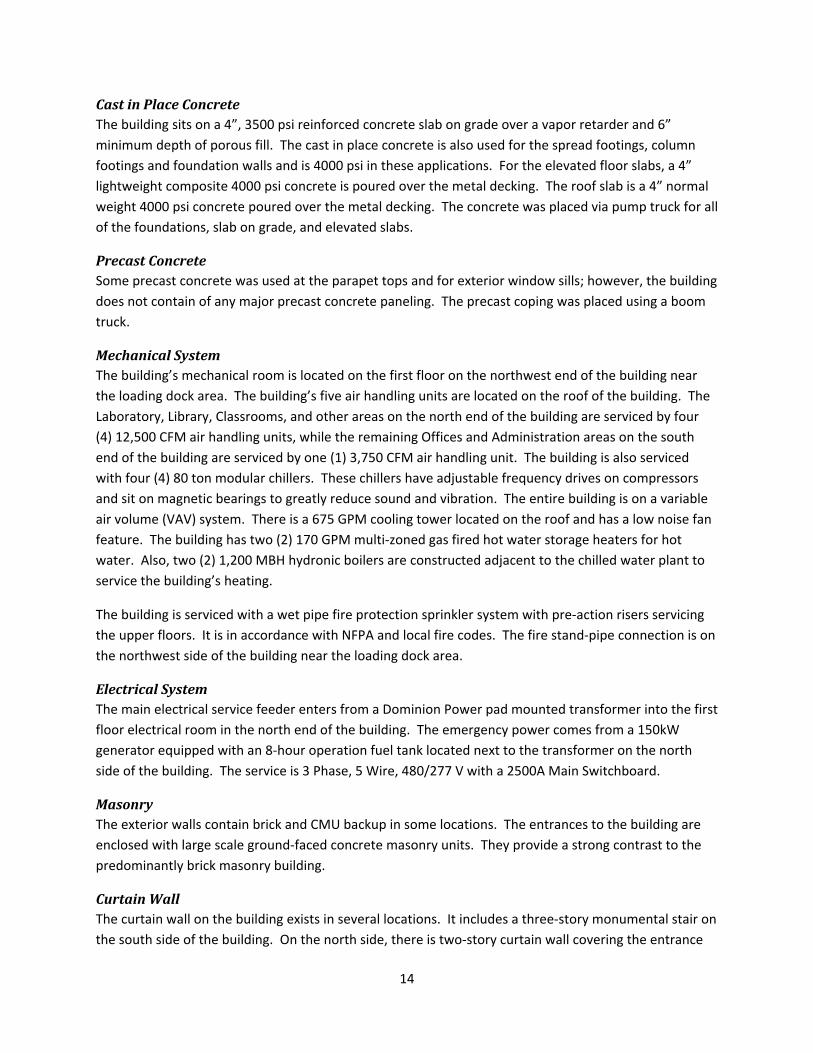
Structural Steel Frame The building has typical elevated composite slabs (4” of lightweight 4000 psi concrete topping over a 1 ½” x 20 gauge VLR composite deck) supported by typical W16 floor beams and W10 columns. The roof is a composite slab (4” of normal weight 4000 psi concrete over a 1 ½” x 22 gauge type B composite deck) which is also supported by a typical W16 composite floor beam system.
The crane used to erect the structure was a 70 ton lattice boom crane with jib. The length was 175 ft including the 35 ft jib. The crane was on site for roughly five weeks.
Some of the challenges with steel erection were the sequencing of the pieces coming from the mill. Also, since this project is located in a seismic area in Virginia, the structural engineer had to add pieces of 1” flat plates which were connected in the field on the base of each column in the braced bay areas of the project. The flat plates had to be coordinated with each slab pour to be installed before the concrete was poured.
Figure 6, Steel Erection via Lattice Boom Crane
14
Cast in Place Concrete The building sits on a 4”, 3500 psi reinforced concrete slab on grade over a vapor retarder and 6” minimum depth of porous fill. The cast in place concrete is also used for the spread footings, column footings and foundation walls and is 4000 psi in these applications. For the elevated floor slabs, a 4” lightweight composite 4000 psi concrete is poured over the metal decking. The roof slab is a 4” normal weight 4000 psi concrete poured over the metal decking. The concrete was placed via pump truck for all of the foundations, slab on grade, and elevated slabs.
Precast Concrete Some precast concrete was used at the parapet tops and for exterior window sills; however, the building does not contain of any major precast concrete paneling. The precast coping was placed using a boom truck.
Mechanical System The building’s mechanical room is located on the first floor on the northwest end of the building near the loading dock area. The building’s five air handling units are located on the roof of the building. The Laboratory, Library, Classrooms, and other areas on the north end of the building are serviced by four (4) 12,500 CFM air handling units, while the remaining Offices and Administration areas on the south end of the building are serviced by one (1) 3,750 CFM air handling unit. The building is also serviced with four (4) 80 ton modular chillers. These chillers have adjustable frequency drives on compressors and sit on magnetic bearings to greatly reduce sound and vibration. The entire building is on a variable air volume (VAV) system. There is a 675 GPM cooling tower located on the roof and has a low noise fan feature. The building has two (2) 170 GPM multi‐zoned gas fired hot water storage heaters for hot water. Also, two (2) 1,200 MBH hydronic boilers are constructed adjacent to the chilled water plant to service the building’s heating.
The building is serviced with a wet pipe fire protection sprinkler system with pre‐action risers servicing the upper floors. It is in accordance with NFPA and local fire codes. The fire stand‐pipe connection is on the northwest side of the building near the loading dock area.
Electrical System The main electrical service feeder enters from a Dominion Power pad mounted transformer into the first floor electrical room in the north end of the building. The emergency power comes from a 150kW generator equipped with an 8‐hour operation fuel tank located next to the transformer on the north side of the building. The service is 3 Phase, 5 Wire, 480/277 V with a 2500A Main Switchboard.
Masonry The exterior walls contain brick and CMU backup in some locations. The entrances to the building are enclosed with large scale ground‐faced concrete masonry units. They provide a strong contrast to the predominantly brick masonry building.
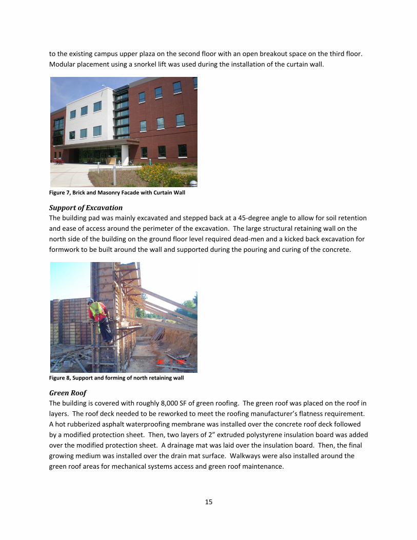
Curtain Wall The curtain wall on the building exists in several locations. It includes a three‐story monumental stair on the south side of the building. On the north side, there is two‐story curtain wall covering the entrance
15
to the existing campus upper plaza on the second floor with an open breakout space on the third floor. Modular placement using a snorkel lift was used during the installation of the curtain wall.
Figure 7, Brick and Masonry Facade with Curtain Wall
Support of Excavation The building pad was mainly excavated and stepped back at a 45‐degree angle to allow for soil retention and ease of access around the perimeter of the excavation. The large structural retaining wall on the north side of the building on the ground floor level required dead‐men and a kicked back excavation for formwork to be built around the wall and supported during the pouring and curing of the concrete.
Figure 8, Support and forming of north retaining wall
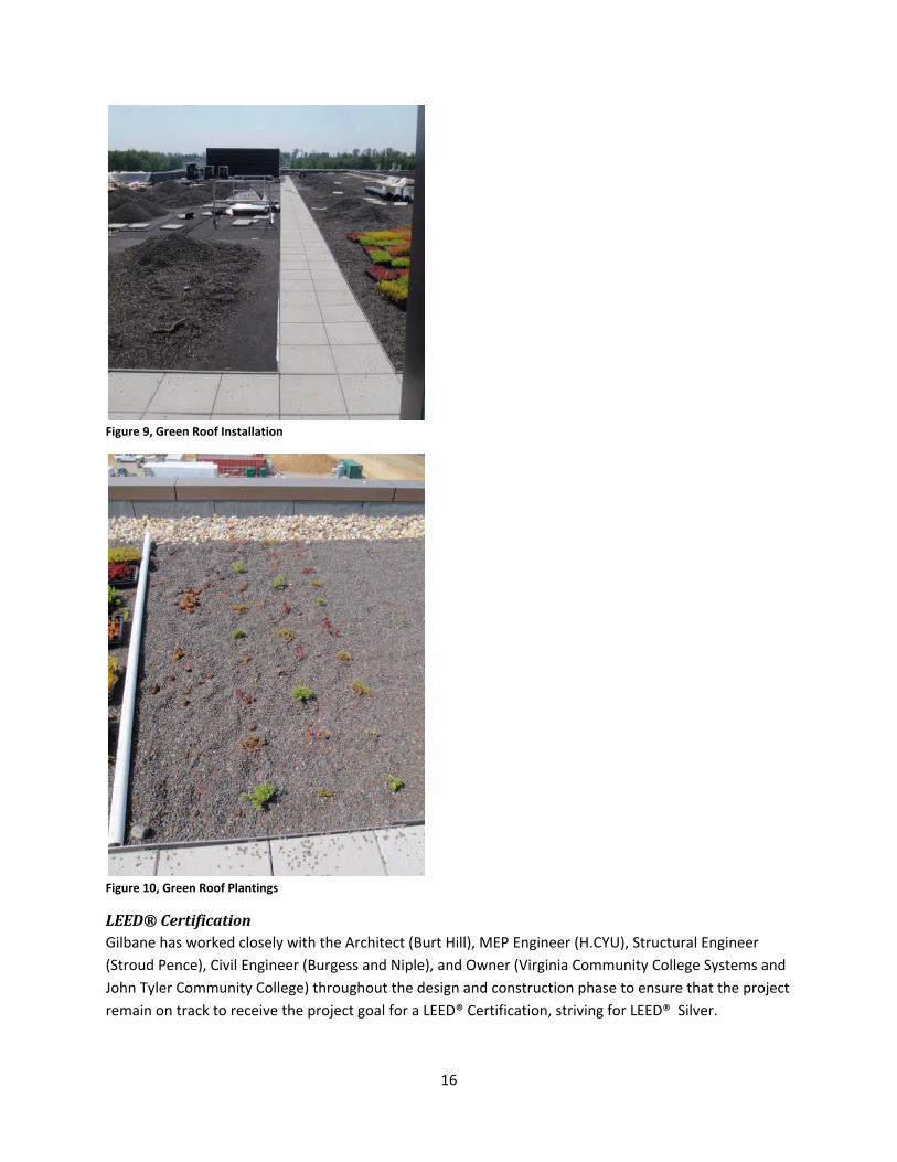
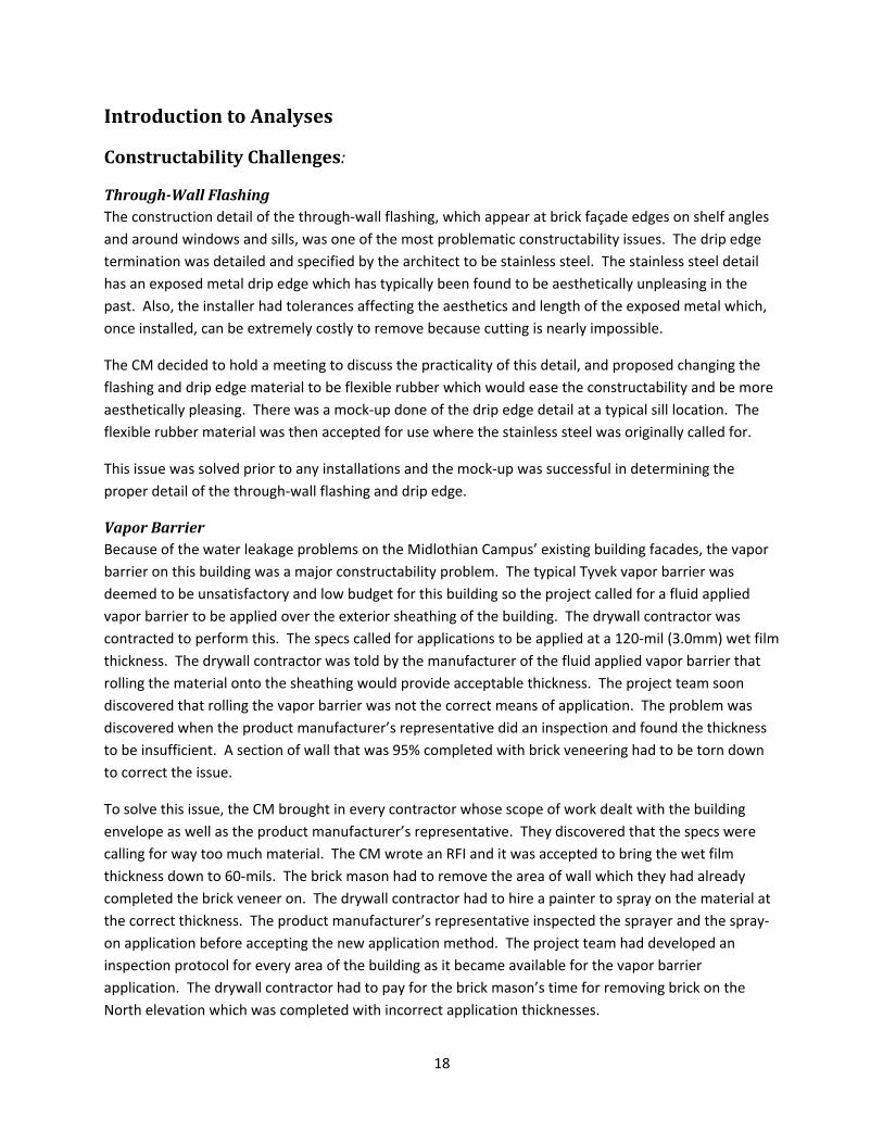
Green Roof The building is covered with roughly 8,000 SF of green roofing. The green roof was placed on the roof in layers. The roof deck needed to be reworked to meet the roofing manufacturer’s flatness requirement. A hot rubberized asphalt waterproofing membrane was installed over the concrete roof deck followed by a modified protection sheet. Then, two layers of 2” extruded polystyrene insulation board was added over the modified protection sheet. A drainage mat was laid over the insulation board. Then, the final growing medium was installed over the drain mat surface. Walkways were also installed around the green roof areas for mechanical systems access and green roof maintenance.
16
Figure 9, Green Roof Installation
Figure 10, Green Roof Plantings
LEED® Certification Gilbane has worked closely with the Architect (Burt Hill), MEP Engineer (H.CYU), Structural Engineer (Stroud Pence), Civil Engineer (Burgess and Niple), and Owner (Virginia Community College Systems and John Tyler Community College) throughout the design and construction phase to ensure that the project remain on track to receive the project goal for a LEED® Certification, striving for LEED® Silver.

17
The project is currently on track to receive a LEED® Certified rating. The project has potential to reach the Silver rating. A Silver rating is achievable if several of the possible additional points are achievable. The building is currently under review for the possible additional points, and a LEED® checklist and plan has been in place since the project’s beginning by Gilbane. The building is pending review of credits for Energy & Atmosphere, Materials & Resources, Indoor Environmental Quality, and Innovation & Design. The building may also receive an additional point after one year of operation when the contracted enhanced commissioning agent performs commissioning review of the building systems.
18
Introduction to Analyses
Constructability Challenges:
ThroughWall Flashing The construction detail of the through‐wall flashing, which appear at brick façade edges on shelf angles and around windows and sills, was one of the most problematic constructability issues. The drip edge termination was detailed and specified by the architect to be stainless steel. The stainless steel detail has an exposed metal drip edge which has typically been found to be aesthetically unpleasing in the past. Also, the installer had tolerances affecting the aesthetics and length of the exposed metal which, once installed, can be extremely costly to remove because cutting is nearly impossible.
The CM decided to hold a meeting to discuss the practicality of this detail, and proposed changing the flashing and drip edge material to be flexible rubber which would ease the constructability and be more aesthetically pleasing. There was a mock‐up done of the drip edge detail at a typical sill location. The flexible rubber material was then accepted for use where the stainless steel was originally called for.
This issue was solved prior to any installations and the mock‐up was successful in determining the proper detail of the through‐wall flashing and drip edge.
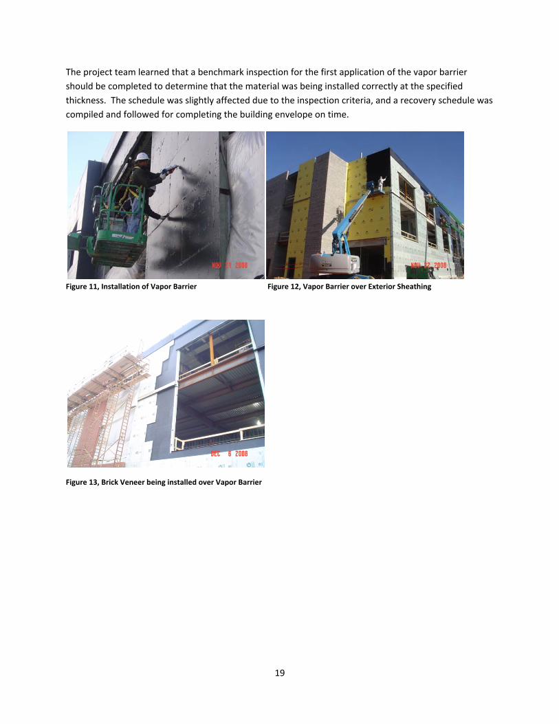
Vapor Barrier Because of the water leakage problems on the Midlothian Campus’ existing building facades, the vapor barrier on this building was a major constructability problem. The typical Tyvek vapor barrier was deemed to be unsatisfactory and low budget for this building so the project called for a fluid applied vapor barrier to be applied over the exterior sheathing of the building. The drywall contractor was contracted to perform this. The specs called for applications to be applied at a 120‐mil (3.0mm) wet film thickness. The drywall contractor was told by the manufacturer of the fluid applied vapor barrier that rolling the material onto the sheathing would provide acceptable thickness. The project team soon discovered that rolling the vapor barrier was not the correct means of application. The problem was discovered when the product manufacturer’s representative did an inspection and found the thickness to be insufficient. A section of wall that was 95% completed with brick veneering had to be torn down to correct the issue.
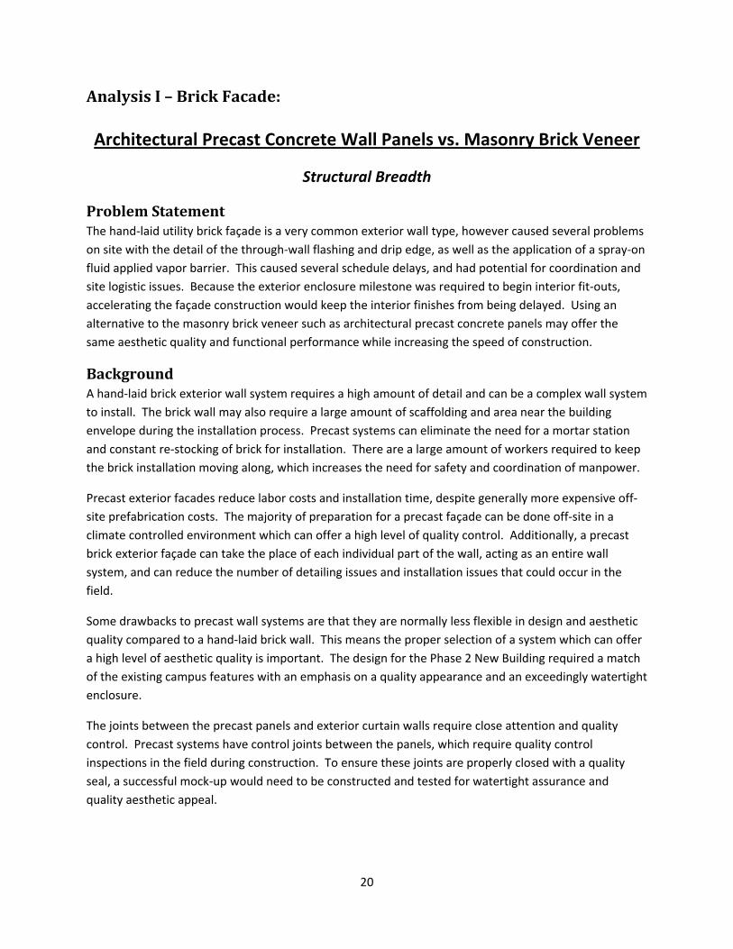
To solve this issue, the CM brought in every contractor whose scope of work dealt with the building envelope as well as the product manufacturer’s representative. They discovered that the specs were calling for way too much material. The CM wrote an RFI and it was accepted to bring the wet film thickness down to 60‐mils. The brick mason had to remove the area of wall which they had already completed the brick veneer on. The drywall contractor had to hire a painter to spray on the material at the correct thickness. The product manufacturer’s representative inspected the sprayer and the spray‐on application before accepting the new application method. The project team had developed an inspection protocol for every area of the building as it became available for the vapor barrier application. The drywall contractor had to pay for the brick mason’s time for removing brick on the North elevation which was completed with incorrect application thicknesses.
19
The project team learned that a benchmark inspection for the first application of the vapor barrier should be completed to determine that the material was being installed correctly at the specified thickness. The schedule was slightly affected due to the inspection criteria, and a recovery schedule was compiled and followed for completing the building envelope on time.
Figure 11, Installation of Vapor Barrier Figure 12, Vapor Barrier over Exterior Sheathing
Figure 13, Brick Veneer being installed over Vapor Barrier
20
Analysis I – Brick Facade:
Architectural Precast Concrete Wall Panels vs. Masonry Brick Veneer
Structural Breadth
Problem Statement The hand‐laid utility brick façade is a very common exterior wall type, however caused several problems on site with the detail of the through‐wall flashing and drip edge, as well as the application of a spray‐on fluid applied vapor barrier. This caused several schedule delays, and had potential for coordination and site logistic issues. Because the exterior enclosure milestone was required to begin interior fit‐outs, accelerating the façade construction would keep the interior finishes from being delayed. Using an alternative to the masonry brick veneer such as architectural precast concrete panels may offer the same aesthetic quality and functional performance while increasing the speed of construction.
Background A hand‐laid brick exterior wall system requires a high amount of detail and can be a complex wall system to install. The brick wall may also require a large amount of scaffolding and area near the building envelope during the installation process. Precast systems can eliminate the need for a mortar station and constant re‐stocking of brick for installation. There are a large amount of workers required to keep the brick installation moving along, which increases the need for safety and coordination of manpower.
Precast exterior facades reduce labor costs and installation time, despite generally more expensive off‐site prefabrication costs. The majority of preparation for a precast façade can be done off‐site in a climate controlled environment which can offer a high level of quality control. Additionally, a precast brick exterior façade can take the place of each individual part of the wall, acting as an entire wall system, and can reduce the number of detailing issues and installation issues that could occur in the field.
Some drawbacks to precast wall systems are that they are normally less flexible in design and aesthetic quality compared to a hand‐laid brick wall. This means the proper selection of a system which can offer a high level of aesthetic quality is important. The design for the Phase 2 New Building required a match of the existing campus features with an emphasis on a quality appearance and an exceedingly watertight enclosure.
The joints between the precast panels and exterior curtain walls require close attention and quality control. Precast systems have control joints between the panels, which require quality control inspections in the field during construction. To ensure these joints are properly closed with a quality seal, a successful mock‐up would need to be constructed and tested for watertight assurance and quality aesthetic appeal.
21
Additionally, the precast wall panels will change the load to the structure which means checking the existing structure is important, and re‐sizing the members might be necessary. The detail of connections to the exterior beams will need to be designed.
Research Method Research began with gaining a better understanding of different precast brick wall systems available. This is conducted by studying literature and case studies of different systems. Once the appropriate system has been chosen for use and panel sizes are determined, structural calculations will be completed to determine if the precast system is a feasible option, or if the structure would need to be re‐sized due to an increased load. A detail of the typical connection at exterior beams will also be determined.
Cost and schedule implications will be determined based on the unit cost of the precast system and erection times. Finally, quality control issues of the selected precast system will be discussed to determine if the precast system can offer similar or better quality than the traditional hand‐laid exterior brick wall system.
Goal The goal of this analysis will be to select an appropriate architectural precast wall system which can offer similar aesthetic quality and watertight functional quality as a hand laid exterior brick wall system. The structural implications will be determined through structural calculations of the load applied to the exterior composite beams connected to the precast panels. This analysis will also determine the resulting cost and schedule implications.
Analysis To begin the analysis, research had been conducted into appropriate architectural precast wall systems. It was important to select a system that can reduce the number of through wall flashing detailing issues and installation issues that could occur in the field. Because the project called for a fluid applied vapor barrier applied over the exterior sheathing of the building which caused schedule delays, it was also important to select a system that eliminated the need of a fluid applied vapor barrier and exterior sheathing. The following criteria were used for the selection of an appropriate system:
• High Quality appearance
• High weatherproof performance
• Cost‐Effective
• Reduced construction schedule
• Proximity of factory to project site
After considering the above criteria in selecting the appropriate system, the following product was selected for use in this analysis.
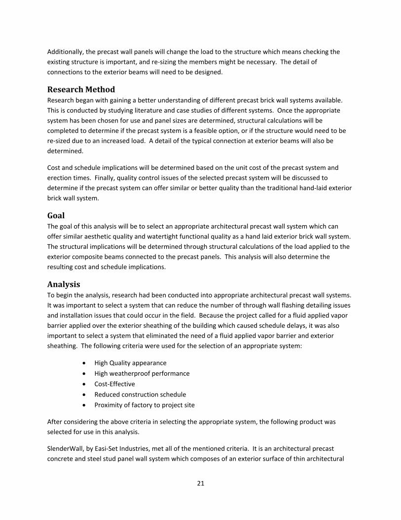
SlenderWall, by Easi‐Set Industries, met all of the mentioned criteria. It is an architectural precast concrete and steel stud panel wall system which composes of an exterior surface of thin architectural
22
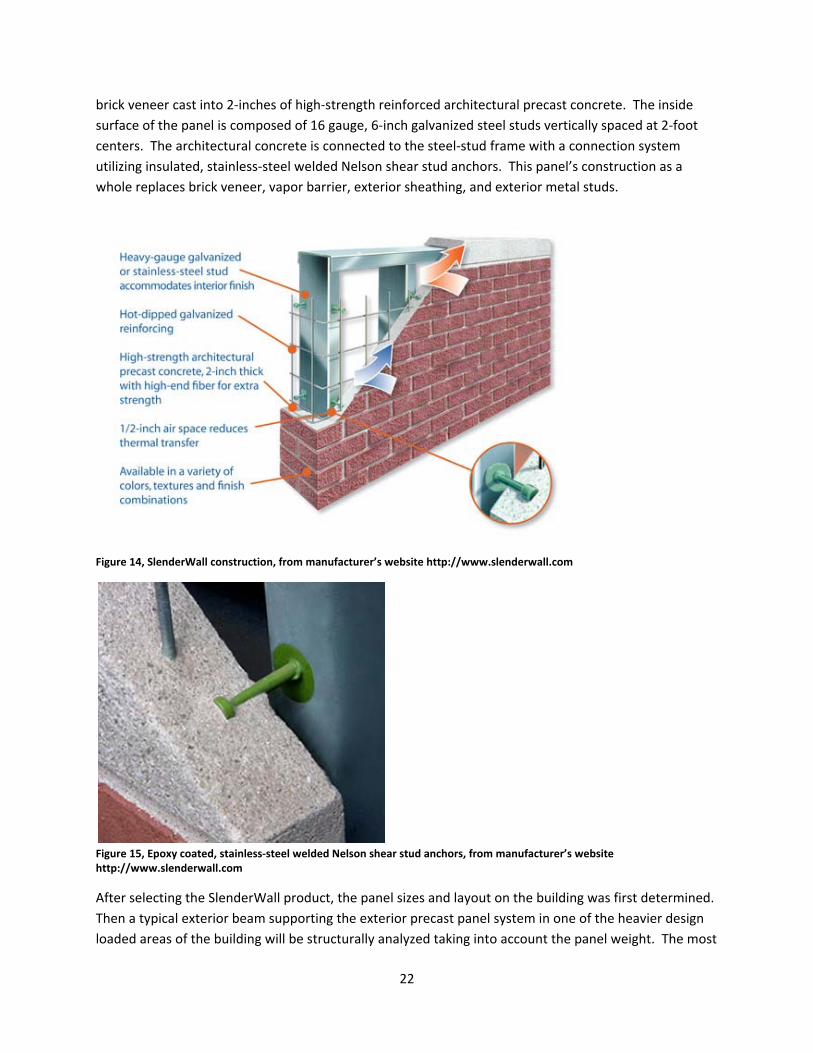
brick veneer cast into 2‐inches of high‐strength reinforced architectural precast concrete. The inside surface of the panel is composed of 16 gauge, 6‐inch galvanized steel studs vertically spaced at 2‐foot centers. The architectural concrete is connected to the steel‐stud frame with a connection system utilizing insulated, stainless‐steel welded Nelson shear stud anchors. This panel’s construction as a whole replaces brick veneer, vapor barrier, exterior sheathing, and exterior metal studs.
Figure 14, SlenderWall construction, from manufacturer’s website http://www.slenderwall.com
Figure 15, Epoxy coated, stainless‐steel welded Nelson shear stud anchors, from manufacturer’s website http://www.slenderwall.com
After selecting the SlenderWall product, the panel sizes and layout on the building was first determined. Then a typical exterior beam supporting the exterior precast panel system in one of the heavier design loaded areas of the building will be structurally analyzed taking into account the panel weight. The most
23
panel load per lineal foot occurs on the third level beams because the second floor story height of 16‐feet is the largest; making the second floor panels supported by the third floor beams the heaviest load by the panels.
Determining Panel Sizes In consultation with the manufacturer of the SlenderWall panel system, and the use of Autodesk Revit, panel sizes and orientations were determined. The orientation of horizontal panels hung from the spandrel beam of the floor above has been determined to best suit the Phase 2 New building. It is recommended that panel sizes be constructed as large as possible, due to costs being on a fixed “per piece basis”. According to the manufacturer, the most economically sized panels are generally 10‐feet by 35‐feet. Additional shipping fees generally occur when panels larger than 13‐feet by 40‐feet are being delivered due to delivery truck size restrictions. It is not recommended by the manufacturer to exceed 13‐feet by 40‐feet panels. Because story heights on the Phase 2 New building are over 13‐feet (1st and 3rd story height is 14‐feet, 2nd story height is 16‐feet), the limiting length of the panels will be 13‐feet wide in the horizontal direction.
See Appendix C: Precast Panel Takeoffs.
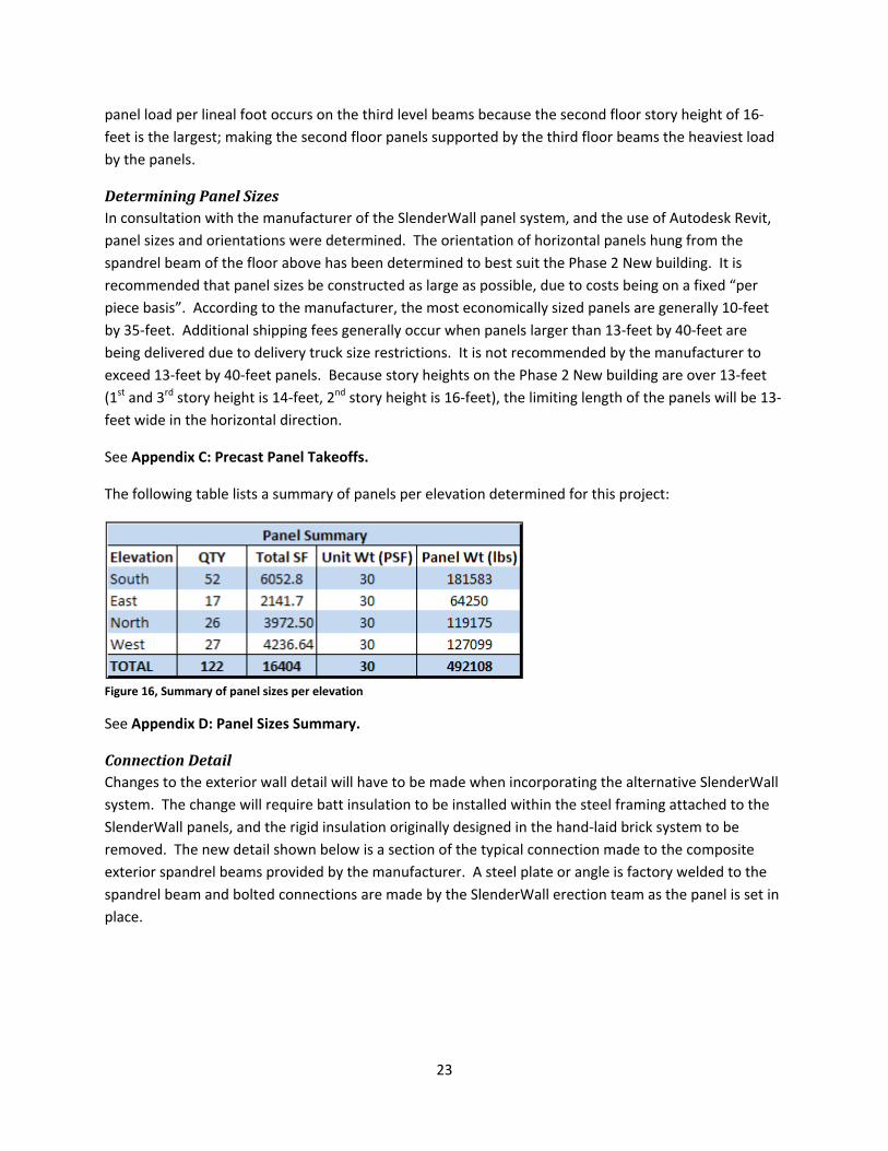
The following table lists a summary of panels per elevation determined for this project:
Figure 16, Summary of panel sizes per elevation
See Appendix D: Panel Sizes Summary.
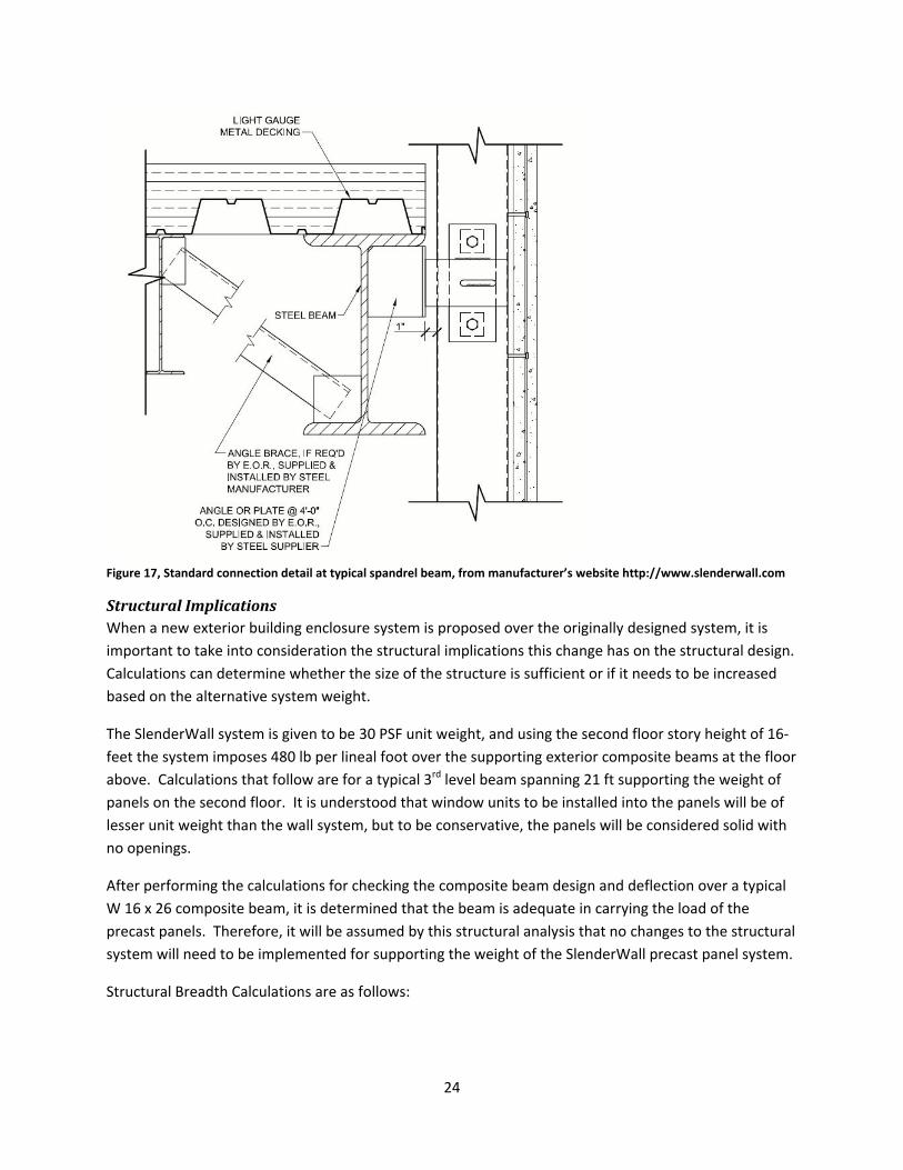
Connection Detail Changes to the exterior wall detail will have to be made when incorporating the alternative SlenderWall system. The change will require batt insulation to be installed within the steel framing attached to the SlenderWall panels, and the rigid insulation originally designed in the hand‐laid brick system to be removed. The new detail shown below is a section of the typical connection made to the composite exterior spandrel beams provided by the manufacturer. A steel plate or angle is factory welded to the spandrel beam and bolted connections are made by the SlenderWall erection team as the panel is set in place.
24
Figure 17, Standard connection detail at typical spandrel beam, from manufacturer’s website http://www.slenderwall.com
Structural Implications When a new exterior building enclosure system is proposed over the originally designed system, it is important to take into consideration the structural implications this change has on the structural design. Calculations can determine whether the size of the structure is sufficient or if it needs to be increased based on the alternative system weight.
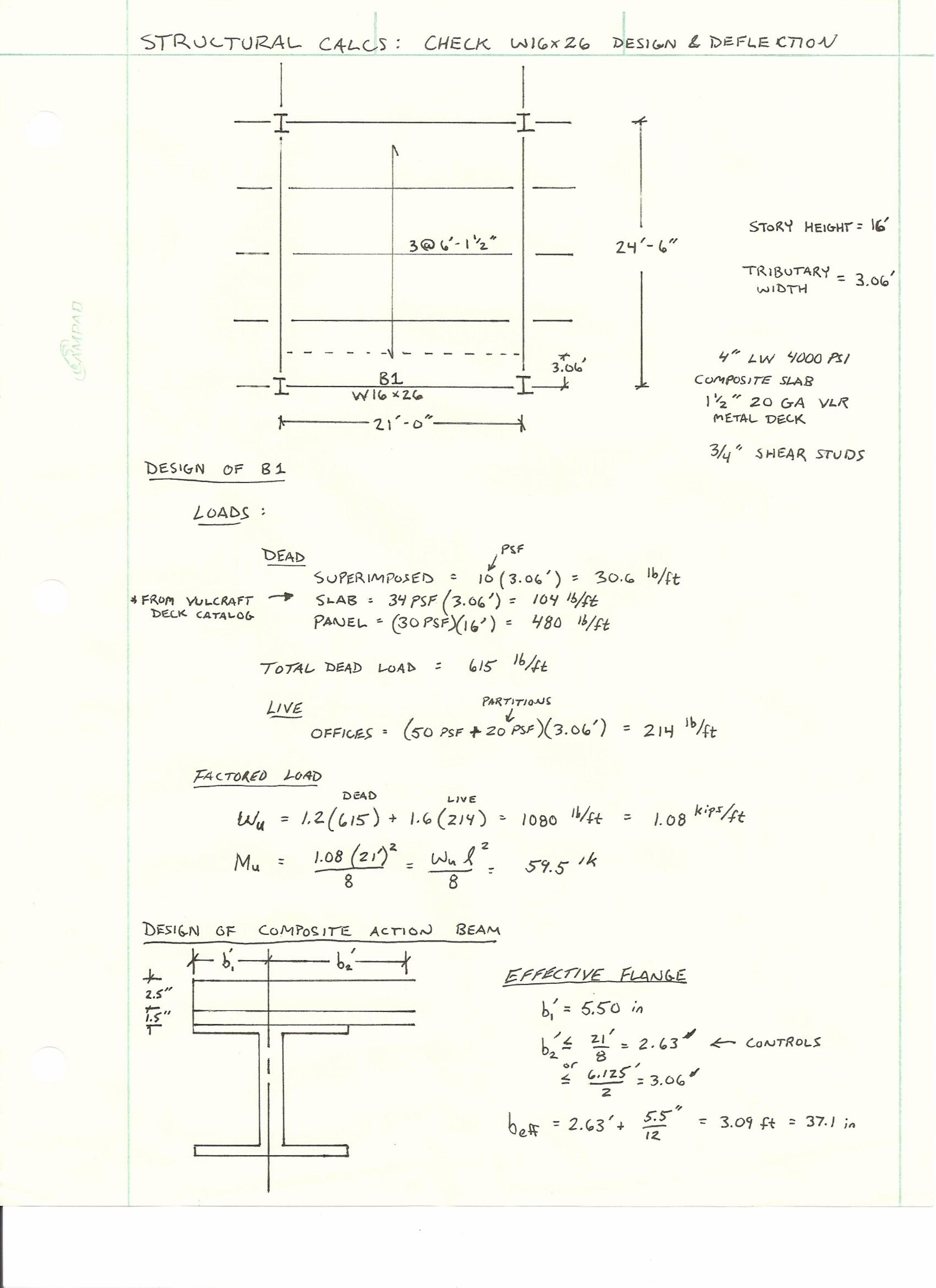
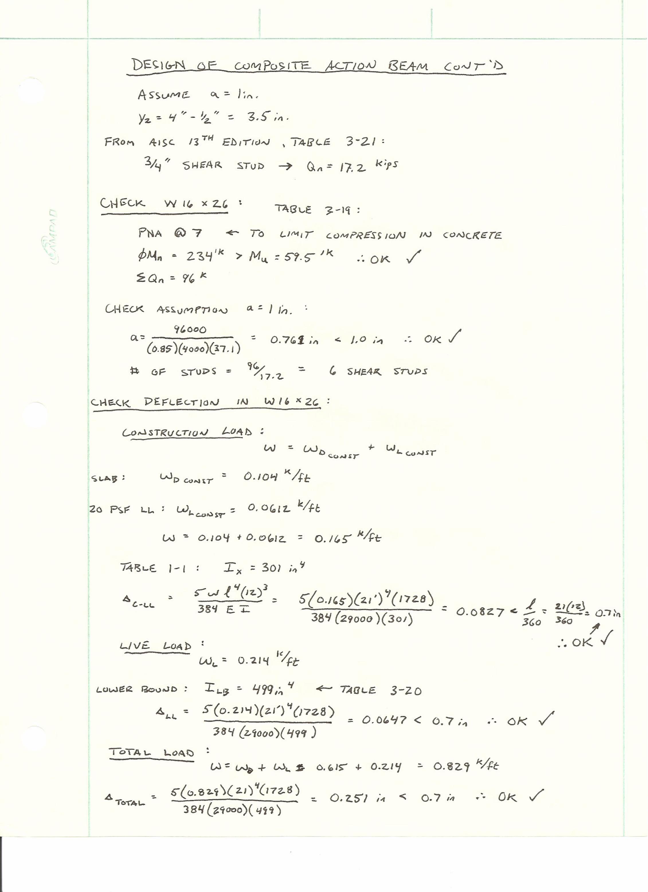
The SlenderWall system is given to be 30 PSF unit weight, and using the second floor story height of 16‐feet the system imposes 480 lb per lineal foot over the supporting exterior composite beams at the floor above. Calculations that follow are for a typical 3rd level beam spanning 21 ft supporting the weight of panels on the second floor. It is understood that window units to be installed into the panels will be of lesser unit weight than the wall system, but to be conservative, the panels will be considered solid with no openings.
After performing the calculations for checking the composite beam design and deflection over a typical W 16 x 26 composite beam, it is determined that the beam is adequate in carrying the load of the precast panels. Therefore, it will be assumed by this structural analysis that no changes to the structural system will need to be implemented for supporting the weight of the SlenderWall precast panel system.
Structural Breadth Calculations are as follows:
27
Quality Control Issues Because the previous buildings on the John Tyler Midlothian Campus had extreme weathering and waterproofing issues, as well as problems with the drip edge details and fluid applied vapor barrier, quality control of the exterior wall system is very important to look at. When choosing the proper precast exterior wall system to replace the hand laid utility brick, functional and aesthetic quality is a top priority in this case.
Traditional hand laid systems offer traditional and proven quality in construction, however the Slender Wall Architectural Precast Concrete and Steel Stud Building Panel offers Second Nature Architectural Precast Concrete Brick. This precast concrete brick is Class “A” and is approved by historical societies and architects for use of high profile architectural projects. The benefit to this system is there are no leaking brick joints, because the brick is cast into the precast concrete section. Slender Wall manufacturers work closely with architects, owners and designers to develop custom samples and designs to meet the proper quality requirements of the project. Successful mock‐ups are made prior to installing the panels, and this is done to the architect’s requirements before accepting the final design of the system.
The Slender Wall system also provides a 100% thermal‐break/air barrier. The 2‐inch of concrete facing is secured to the steel framing by epoxy‐coated stainless‐steel Nelson anchors. This provides the concrete with response to thermal gradients independently because a ½ inch air space is left between the precast concrete and the stud frame. This provides a reduction in thermal transfer which could provide additional reduction in heating and cooling costs.
Joints and reveals are areas of big concern for leakage and infiltration of moisture between the panels. The SlenderWall is designed with a ¾‐inch joint between panels and reveals can vary in size according to the design needs. The joint between panels can be finished with ¾‐inch backer rod covered by a ½‐inch layer of caulking to provide a watertight seal. A close quality‐control inspection of these joints would need to occur during the construction of the panels in order to guarantee a high quality seal is maintained.
Schedule The original exterior building enclosure schedule had duration of 79 days. The hand‐laid system required exterior studs, exterior sheathing, and the fluid applied vapor barrier to be installed before the masonry contractor could begin setting the hand‐laid brick. Additionally, the original building skin schedule required the exterior skin to be installed while the 2nd floor composite slab was being poured and steel framing was still being completed. This causes site congestion and logistical issues when planning material deliveries and unloading.
When incorporating the SlenderWall system into the building skin schedule, durations were obtained from the SlenderWall manufacturer. Panels are typically installed using the precast contractor’s crane, which means the precast panels can be erected without major crane interruptions. The manufacturer of SlenderWall estimates an average of 19 minutes from truck to setting and installing per panel. Also,
28
items such as exterior studs, sheathing, and vapor barrier could be eliminated from the schedule because the SlenderWall already contains these items.
Based on the panel layout and sizes determined in this analysis and utilizing the durations and adding additional time for finishing the joints and caulking, a new schedule for the building enclosure was created. The same erection pattern as the original schedule was incorporated when planning the new schedule, which starts on the western end of the North elevation and moving counter‐clockwise around the building.
See Appendix E: Detailed Project Schedule –Alternative Exterior Façade.
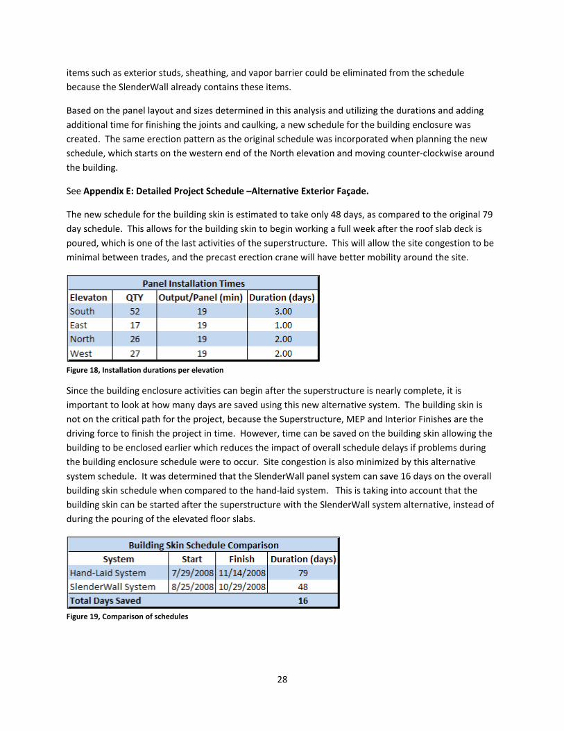
The new schedule for the building skin is estimated to take only 48 days, as compared to the original 79 day schedule. This allows for the building skin to begin working a full week after the roof slab deck is poured, which is one of the last activities of the superstructure. This will allow the site congestion to be minimal between trades, and the precast erection crane will have better mobility around the site.
Figure 18, Installation durations per elevation
Since the building enclosure activities can begin after the superstructure is nearly complete, it is important to look at how many days are saved using this new alternative system. The building skin is not on the critical path for the project, because the Superstructure, MEP and Interior Finishes are the driving force to finish the project in time. However, time can be saved on the building skin allowing the building to be enclosed earlier which reduces the impact of overall schedule delays if problems during the building enclosure schedule were to occur. Site congestion is also minimized by this alternative system schedule. It was determined that the SlenderWall panel system can save 16 days on the overall building skin schedule when compared to the hand‐laid system. This is taking into account that the building skin can be started after the superstructure with the SlenderWall system alternative, instead of during the pouring of the elevated floor slabs.
Figure 19, Comparison of schedules
29
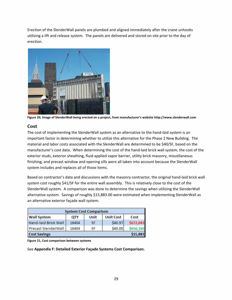
Erection of the SlenderWall panels are plumbed and aligned immediately after the crane unhooks utilizing a lift and release system. The panels are delivered and stored on site prior to the day of erection.
Figure 20, Image of SlenderWall being erected on a project, from manufacturer’s website http://www.slenderwall.com
Cost The cost of implementing the SlenderWall system as an alternative to the hand‐laid system is an important factor in determining whether to utilize this alternative for the Phase 2 New Building. The material and labor costs associated with the SlenderWall are determined to be $40/SF, based on the manufacturer’s cost data. When determining the cost of the hand‐laid brick wall system, the cost of the exterior studs, exterior sheathing, fluid applied vapor barrier, utility brick masonry, miscellaneous finishing, and precast window and opening sills were all taken into account because the SlenderWall system includes and replaces all of those items.
Based on contractor’s data and discussions with the masonry contractor, the original hand‐laid brick wall system cost roughly $41/SF for the entire wall assembly. This is relatively close to the cost of the SlenderWall system. A comparison was done to determine the savings when utilizing the SlenderWall alternative system. Savings of roughly $15,883.00 were estimated when implementing SlenderWall as an alternative exterior façade wall system.
Figure 21, Cost comparison between systems
See Appendix F: Detailed Exterior Façade Systems Cost Comparison.

30
Conclusions and Recommendations Based on the information presented in this technical analysis, it has been determined that implementing the alternative SlenderWall architectural precast concrete and steel stud panel wall system in lieu of the hand laid brick system would be a beneficial change to the exterior façade. The SlenderWall system allows the building skin schedule to be reduced by 16 days and begin after the superstructure is completed. When compared to the original schedule with the hand laid brick, which starts while the second floor slab is still being poured, the alternative SlenderWall system will greatly decrease site congestion during the superstructure phase. Also, the decision to use the SlenderWall system has been determined to reduce upfront costs by $15,883 when compared to using hand‐laid brick.
The quality of the SlenderWall precast system would be the other determining factor in the decision to implement this alternative system to the hand‐laid brick. While SlenderWall can offer high quality architectural precast brick to match the aesthetic requirements of the architect, it would still be viewed by some to have a “precast” look to the finished product due to joints between panels. However, a successful mock‐up of the system can be completed before installation, and closely monitored installation and quality control checks on the finishing of the joints can assure a quality finish. Additionally, the SlenderWall system would offer an exterior enclosure with no leaking brick joints, where the hand laid brick system may have imperfections in the mortar seal between individual bricks.
The decision to implement the alternative exterior façade system would ultimately be up to John Tyler Community College. Depending on the acceptance of quality and aesthetic appeal, the SlenderWall system will provide a 16 day reduction in building skin installation while minimizing site congestion during the superstructure phase and offer an estimated $15,883 in upfront cost savings.
31
Analysis II – Roofing System:
TPO “Cool” Roof vs. Green Roof System
M.A.E. Requirements
Problem Statement The roof system installed on the Phase 2 New Building consists of 19,600 SF of an inverted roof membrane assembly (IRMA) ballasted roof system, with 8,300 square feet of the IRMA covered with an extensive green roof system. An alternative system could be selected with similar thermal properties. There are less expensive roofing alternatives that can potentially provide similar requirements for LEED® and can result in upfront cost savings. The different systems available include a wide variety of green roof systems and also lighter “cool” white roof membranes.
Background Green roofing systems such as the one installed on the Phase 2 New Building provide many potential benefits in terms of energy and conservation. They provide a substantial amount of storm water runoff control by absorbing the rainwater in the soils for the plantings. They reduce the heat‐island effect contributed by buildings with dark roofing membranes. They create a wildlife habitat and improve the aesthetic environment. Also, they add potential energy saving benefits through the reduction of heat transfer through the roof of the building.
There are many alternative and inexpensive roofing systems on the market that can provide excellent thermal insulation and can reduce energy costs as well as minimize impacts on the environment. An alternative roofing system such as a single‐ply membrane “cool” roofing system can potentially offer similar requirements for LEED® than that of a green roof.
Thermoplastic single‐ply roofing membranes are one of the fastest growing roofing systems that offer performance and installation advantages over green roof systems. They can offer a high heat‐reflective and energy efficient roofing surface, and provide exceptional resistance to ultraviolet, ozone and chemical exposure. They can offer a reduction in operational costs and upfront costs because they consist of inexpensive materials and can be installed very quickly compared to a green roof system.
Research Method Research into the available alternative roofing systems and products will provide a background of roofing knowledge. Consulting the roofing contractor for the Phase 2 New Building to acquire insight and opinion on the best alternative roofing system will help determine what type of system would work best for this project.
Comparing product information and overall quality will be important for choosing the best product. Once a product is chosen as the alternative roofing system, the configuration of this product will be determined to match the suggested R‐value of the green roof system. The cost and schedule implications will be analyzed, and a comparison will help determine which system is more economical.
32
Also, research of the quality issues and comparing between the green roof systems installed and the alternative system will be completed.
Goal The goal of this analysis will be to determine the impacts associated with removing the designed roof system and utilizing a fully adhered single ply TPO “cool” roof membrane system. The focus of study will be the difference in quality, construction costs, and the LEED® requirements that must be met in order to receive credit for the roof.
Master of Architectural Engineering Requirements In order to satisfy the M.A.E. research requirements, knowledge learned within graduate level courses are incorporated into this analysis of an alternative roofing system. Knowledge and information gained from AE 542: Building Enclosure Science and Design, which focuses on developing an understanding of the nature, importance, functions, and performance of the building envelope, is shown through calculations and comparison of the thermal properties and heat transfer through the roofing systems. Methods learned for determining the R‐value of a system composed of various components and the heat transfer through the system are completed within this analysis.
Additionally, knowledge from AE 597D: Sustainable Building Methods, focusing on strategies and technologies for green building and sustainable construction and understanding how to minimize impacts of buildings on the environment, will help determine appropriate system materials and LEED® implications within this analysis of alternative roofing systems. Comparing the potential LEED® credits of the analyzed roofing systems will be performed within this analysis.
Analysis After research into various roofing systems and discussions with the roofing contractor for the Phase 2 New Building Project, it has been determined that the best alternative system for incorporation in this analysis is a light colored or white thermoplastic (TPO) singly ply membrane system fully adhered to the composite concrete roof slab. When comparing the systems, it is important to note that energy costs and differences in reductions will not be compared due to limited time and availability, but are important factors when considering these systems.
The green roof system installed on the Phase 2 New Building is estimated to provide an R‐30 thermal insulation value, but usually green roof systems actually provide a much greater value. Therefore, it is important to design the alternative TPO “cool” roof system to provide a very similar thermal performance value. Also, in areas which are not covered by green roof, a ballasted IRMA roof system was installed over the hot rubberized asphalt waterproofing membrane. It will be important to remove the hot rubberized asphalt membrane when considering the alternative TPO “cool” roof system. With this in mind, the next step is to configure the roofing construction to provide similar thermal properties as the green roof.
33
Thermal Properties Since the green roof system that was installed on the Phase 2 New Building had an expected R‐value of R‐30, it is important that the design of the alternative roofing system utilizing a single‐ply TPO system can provide similar thermal performance. To determine the R‐value, a spreadsheet tool was used to configure the proper thickness of materials in order to achieve R‐30. The design temperatures for determining the R‐Value and heat transfer through the roof were taken from Richmond, VA temperatures.
See Appendix G: TPO “Cool” Roof Thermal Properties.
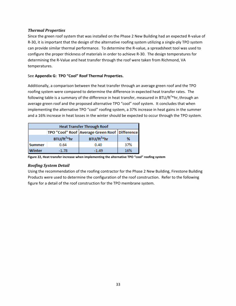
Additionally, a comparison between the heat transfer through an average green roof and the TPO roofing system were compared to determine the difference in expected heat transfer rates. The following table is a summary of the difference in heat transfer, measured in BTU/ft2*hr, through an average green roof and the proposed alternative TPO “cool” roof system. It concludes that when implementing the alternative TPO “cool” roofing system, a 37% increase in heat gains in the summer and a 16% increase in heat losses in the winter should be expected to occur through the TPO system.
Figure 22, Heat transfer increase when implementing the alternative TPO “cool” roofing system
Roofing System Detail Using the recommendation of the roofing contractor for the Phase 2 New Building, Firestone Building Products were used to determine the configuration of the roof construction. Refer to the following figure for a detail of the roof construction for the TPO membrane system.
34
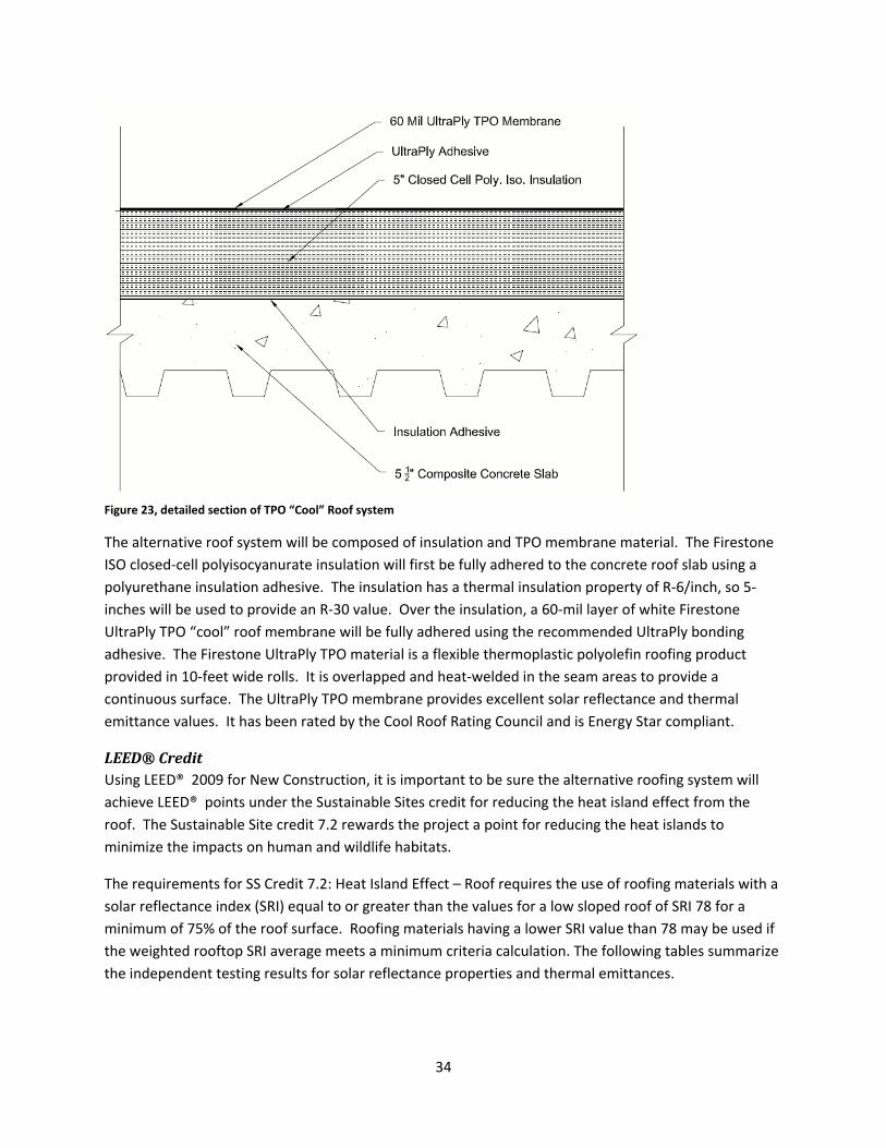
Figure 23, detailed section of TPO “Cool” Roof system
The alternative roof system will be composed of insulation and TPO membrane material. The Firestone ISO closed‐cell polyisocyanurate insulation will first be fully adhered to the concrete roof slab using a polyurethane insulation adhesive. The insulation has a thermal insulation property of R‐6/inch, so 5‐inches will be used to provide an R‐30 value. Over the insulation, a 60‐mil layer of white Firestone UltraPly TPO “cool” roof membrane will be fully adhered using the recommended UltraPly bonding adhesive. The Firestone UltraPly TPO material is a flexible thermoplastic polyolefin roofing product provided in 10‐feet wide rolls. It is overlapped and heat‐welded in the seam areas to provide a continuous surface. The UltraPly TPO membrane provides excellent solar reflectance and thermal emittance values. It has been rated by the Cool Roof Rating Council and is Energy Star compliant.
LEED® Credit Using LEED® 2009 for New Construction, it is important to be sure the alternative roofing system will achieve LEED® points under the Sustainable Sites credit for reducing the heat island effect from the roof. The Sustainable Site credit 7.2 rewards the project a point for reducing the heat islands to minimize the impacts on human and wildlife habitats.
The requirements for SS Credit 7.2: Heat Island Effect – Roof requires the use of roofing materials with a solar reflectance index (SRI) equal to or greater than the values for a low sloped roof of SRI 78 for a minimum of 75% of the roof surface. Roofing materials having a lower SRI value than 78 may be used if the weighted rooftop SRI average meets a minimum criteria calculation. The following tables summarize the independent testing results for solar reflectance properties and thermal emittances.
35
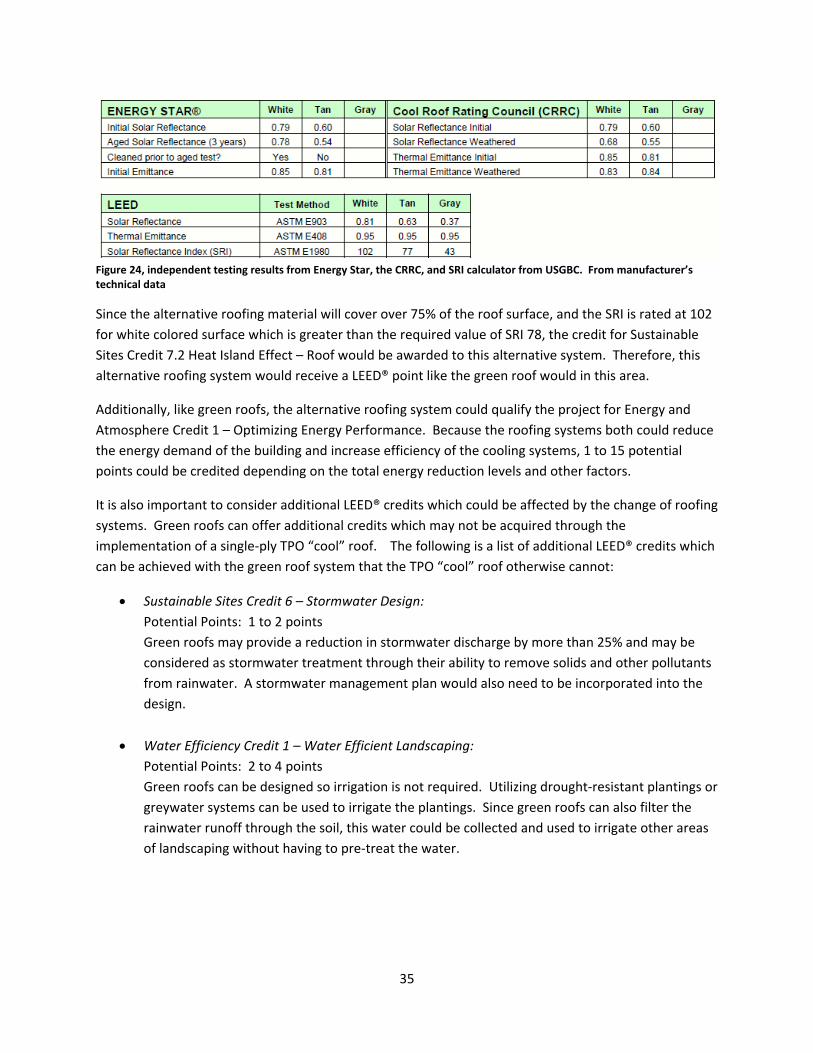
Figure 24, independent testing results from Energy Star, the CRRC, and SRI calculator from USGBC. From manufacturer’s technical data
Since the alternative roofing material will cover over 75% of the roof surface, and the SRI is rated at 102 for white colored surface which is greater than the required value of SRI 78, the credit for Sustainable Sites Credit 7.2 Heat Island Effect – Roof would be awarded to this alternative system. Therefore, this alternative roofing system would receive a LEED® point like the green roof would in this area.
Additionally, like green roofs, the alternative roofing system could qualify the project for Energy and Atmosphere Credit 1 – Optimizing Energy Performance. Because the roofing systems both could reduce the energy demand of the building and increase efficiency of the cooling systems, 1 to 15 potential points could be credited depending on the total energy reduction levels and other factors.
It is also important to consider additional LEED® credits which could be affected by the change of roofing systems. Green roofs can offer additional credits which may not be acquired through the implementation of a single‐ply TPO “cool” roof. The following is a list of additional LEED® credits which can be achieved with the green roof system that the TPO “cool” roof otherwise cannot:
• Sustainable Sites Credit 6 – Stormwater Design: Potential Points: 1 to 2 points Green roofs may provide a reduction in stormwater discharge by more than 25% and may be considered as stormwater treatment through their ability to remove solids and other pollutants from rainwater. A stormwater management plan would also need to be incorporated into the design.
• Water Efficiency Credit 1 – Water Efficient Landscaping: Potential Points: 2 to 4 points Green roofs can be designed so irrigation is not required. Utilizing drought‐resistant plantings or greywater systems can be used to irrigate the plantings. Since green roofs can also filter the rainwater runoff through the soil, this water could be collected and used to irrigate other areas of landscaping without having to pre‐treat the water.
36
• Innovation and Design Process Potential Points: 1 point Green roofs may qualify for an additional point in this area by improving the workplace environment or by creating an educational laboratory. This depends on the intended uses of the green roof system by the owner.
Quality Issues There are specific measures that must be taken so the roofing surface is not damaged when it comes to protecting the roofing surfaces after they are installed for mechanical equipment and other MEP work to be installed on the roof without damaging the membrane surfaces. The quality control of the membrane seal and quality construction checks would typically occur during and immediately after the installation to assure that other trades would not be at fault for damages and poor construction. Typically, plywood protection is installed to protect roof surfaces so that other trades can work. Once the project is wrapping up, the plywood protection is removed from protected surfaces. The green roof plantings typically don’t occur until after the MEP trades are done working on the roof, late in the project. For quality of the “cool” white surface to be guaranteed, the surface is usually washed and cleaned to be sure that dirt, debris, or any other materials are not taking away from its reflective properties.
Schedule The original roofing schedule included several activities and mobilizations. The roof membrane was installed in 23 days. The green roof and paver system around the green roof required an additional 10 days to install the growing medium and planting the sedums. This had to be done later in the schedule, which meant an additional mobilization had to occur for the roofing contractor. The original designed roofing membrane consisted of hot rubberized asphalt over the roof deck, with a ballasted IRMA roofing membrane installed over the waterproof membrane. The green roof was also installed over the hot rubberized asphalt waterproofing membrane. A large amount of growing medium and sedum plantings had to be delivered and stored on site prior to the installation.
When incorporating the single‐ply white TPO “cool” roof membrane system into the schedule, durations were obtained from discussions with the roofing contractor. The alternative roofing membrane was determined to be able to be installed in the same 23 days as the original roofing membrane. Schedule items such as installing the growing medium for the green roof, installing the pavers around the edge of the green roof, and planting the sedums could eliminated from the schedule. Based on this reduction, the re‐mobilization for installing the green roofing system could be eliminated saving roughly 10 days of installation time.
It is important to note some difficulties and challenges with scheduling and planning the installation of the two roofing systems being analyzed. Mobilization and staging areas are important for green roof systems, because large quantities of soil or growing media must be delivered to site and stored prior to the installation of the plantings. Additionally, coordination issues arise when laying out the plantings that are ready to be transferred from the ground to the roof. Having the proper space is crucial for planning the installation of the green roof. There are many mobilizations that must occur to get all of
37
the proper components on site and moved to the roof in time for installations. Also, for the installation of the single‐ply TPO “cool” roof system, the roofing contractor typically prefers to have a clear working space on the roof. The TPO system components would be installed all within one mobilization, and can all be delivered to the roof for storage until the installation occurs. This creates less staging area on the ground and site congestion is minimized.
Cost The upfront cost of implementing the single‐ply TPO “cool” roof system as an alternative to the original roof membrane and green roof will be a factor in determining whether to utilize this alternative for the Phase 2 New Building. The material and labor costs associated with the TPO roofing system are determined to be $8.00/SF, based on the roofing contractor’s estimate.
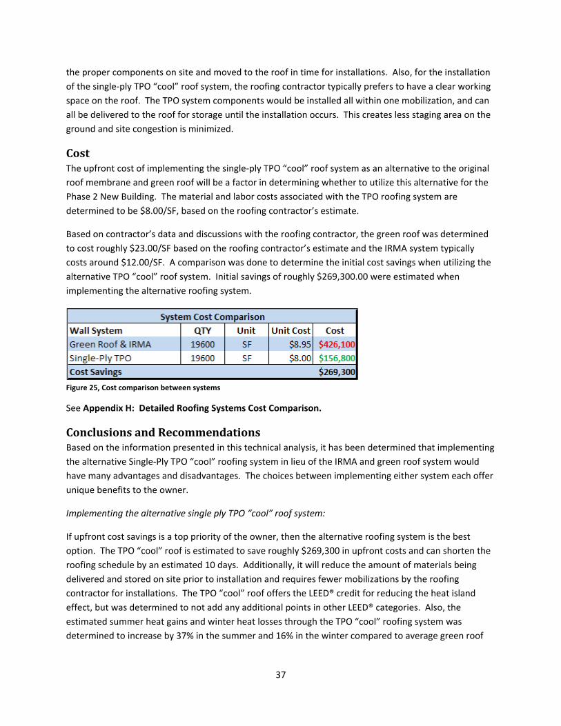
Based on contractor’s data and discussions with the roofing contractor, the green roof was determined to cost roughly $23.00/SF based on the roofing contractor’s estimate and the IRMA system typically costs around $12.00/SF. A comparison was done to determine the initial cost savings when utilizing the alternative TPO “cool” roof system. Initial savings of roughly $269,300.00 were estimated when implementing the alternative roofing system.
Figure 25, Cost comparison between systems
See Appendix H: Detailed Roofing Systems Cost Comparison.
Conclusions and Recommendations Based on the information presented in this technical analysis, it has been determined that implementing the alternative Single‐Ply TPO “cool” roofing system in lieu of the IRMA and green roof system would have many advantages and disadvantages. The choices between implementing either system each offer unique benefits to the owner.
Implementing the alternative single ply TPO “cool” roof system:
If upfront cost savings is a top priority of the owner, then the alternative roofing system is the best option. The TPO “cool” roof is estimated to save roughly $269,300 in upfront costs and can shorten the roofing schedule by an estimated 10 days. Additionally, it will reduce the amount of materials being delivered and stored on site prior to installation and requires fewer mobilizations by the roofing contractor for installations. The TPO “cool” roof offers the LEED® credit for reducing the heat island effect, but was determined to not add any additional points in other LEED® categories. Also, the estimated summer heat gains and winter heat losses through the TPO “cool” roofing system was determined to increase by 37% in the summer and 16% in the winter compared to average green roof

38
thermal properties. This means that additional heating and cooling loads will be needed resulting in increased energy costs.
Implementing the original design of an IRMA and green roof system:
Since the Phase 2 New Building is striving for a LEED® certification level of Silver, it will be important for the owner to choose the green roof system to help achieve this goal. Despite the TPO “cool” roofing system saving $269,300 and shortening the roofing system schedule by an estimated 10 days, the green roof and IRMA system can be considered a much better option for energy efficiency in reducing heat gain and heat losses and adding additional LEED® credits. The green roof system may potentially add an estimated 4 to 10 additional LEED® credits over the TPO “cool” roof, and positively attracts a better public image in being “green” and environmentally friendly by having a green roof.
39
Analysis III – Electrical System:
Electrical System ‐ Building Transformer Sizing
Electrical Breadth
Problem Statement The 300 kVA Transformer specified by the utility company suffered a Phase “A” power loss. This caused severe damage to the building automation system only weeks before occupancy. Many of the contacts for the variable‐frequency drives (VFD’s) were fried. This caused several schedule delays prior to the Phase 2 New Building’s first day of occupancy. The removal of the phase protection implies that communication was lost in verifying the building service load and transformer sizing. The power company had to change the 300kVA transformer out for a 750kVA transformer and an insurance claim was filed by the CM. Focusing on the method of sizing the building’s electrical transformer based on the building’s expected power load with quality control of the electrical system design in mind might provide some industry “best practices” that can be used in the future.
Background The electrical system that is designed for a building must be designed with safety, reliability, and efficiency in mind. The quality control that must be done during the design process is very important for delivering a building system that not only meets standards, but performs to expectations. The electrical system and its components can be assured to be reliable, safe, and efficient through the use of quality control during the design. The incorporation of a high level quality control strategy for the electrical system as it relates to the tie with the electric grid will reduce the risk of component failure and can ensure an improved quality design.
However, electrical systems can be very complex and takes a high level of understanding and experience to properly design a very successful system. The quality control associated with electrical systems and the components, as they relate to the grid tie‐in, is an area that may not be well known. This level of quality control may prove to be difficult to guarantee on large complex projects, and the strategy for incorporating this level of QC into the design could be complicated.
Research Method Research began by collecting information from various publications and industry standards dealing with the quality control and electrical system design. This provides a solid basis of information dealing with the measures and strategies for quality control and electrical design. Consulting electrical engineers within the industry is also important to gain their perspective on these issues. Once several “best practices” can be determined and quality control issues are well defined, calculations for sizing for the building transformer can be completed with the electrical grid and building load in mind.
40
Goal Through research and calculations, the building transformer can be sized for the Phase 2 New Building based on the expected building loads. Also, research will determine many quality control issues and provide some industry “best practices” during the design, installation, and maintenance of the electrical system in buildings.
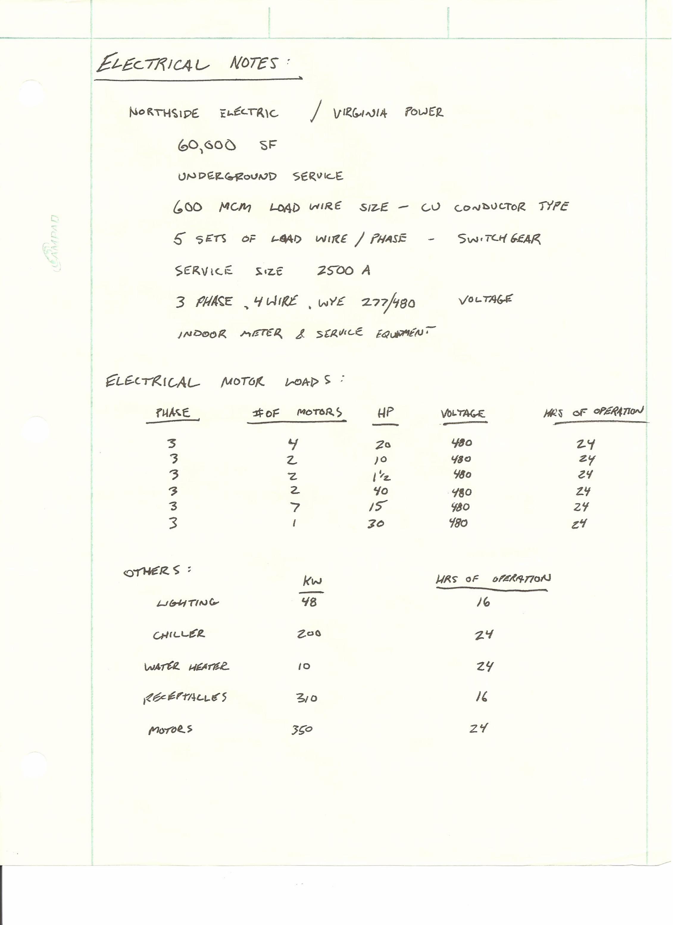
Analysis To begin analysis, it is important to understand building transformers. A building transformer changes the alternating current (AC) of incoming service voltage to AC of another voltage. They are typically used to step down an incoming 4160‐V service to a 480‐V distribution within a building. A smaller transformer within the building is then used to step down the 480‐V to 120‐V for use on the receptacle circuits. In this analysis, the main building transformer will be sized for stepping down the incoming service feed assumed to be a typical 4160‐V to the primary distribution 480‐V within the building.
After research, it has been determined that standard data should be collected to begin sizing a transformer. It is important to first determine the electrical load, voltage required by load, and if the load is designed to operate on three phase power. Second, it is important to determine the supply voltage or amps. The frequency of the line supply and electrical load must be checked to be the same. A three phase transformer is selected which is designed to operate at the same primary input and supply voltage as the secondary output. The engineer would then need to use calculations to determine the kVA rating based on the known voltage and ampere required. Once the known kVA rating is established, it is important to select a three phase transformer with a standard kVA capacity of equal to or greater than that needed to operate the building loads.
The Phase 2 New Building utilizes a 750 kVA transformer. It has been determined that in buildings with transformer capacities over 300 kVA, it is good practice to complete calculations to compare the operating costs of various types. Assuming normal operating cycles and loading, two transformers were compared. The first transformer, a dry type 750kVA transformer designed for an 80°C (144°F) rise in temperature, and the second for a 150°C (270°F) rise in temperature. Based on a $0.07/kWh energy cost, the lower energy waste of the more expensive 80°C unit will repay the first‐cost in about 4 years. Using a 30‐year life, with 8% fixed capital costs, and a 3% annual cost escalation, the life‐cycle costs of the 80°C unit is roughly $10,000.00 less than that of the 150°C unit.
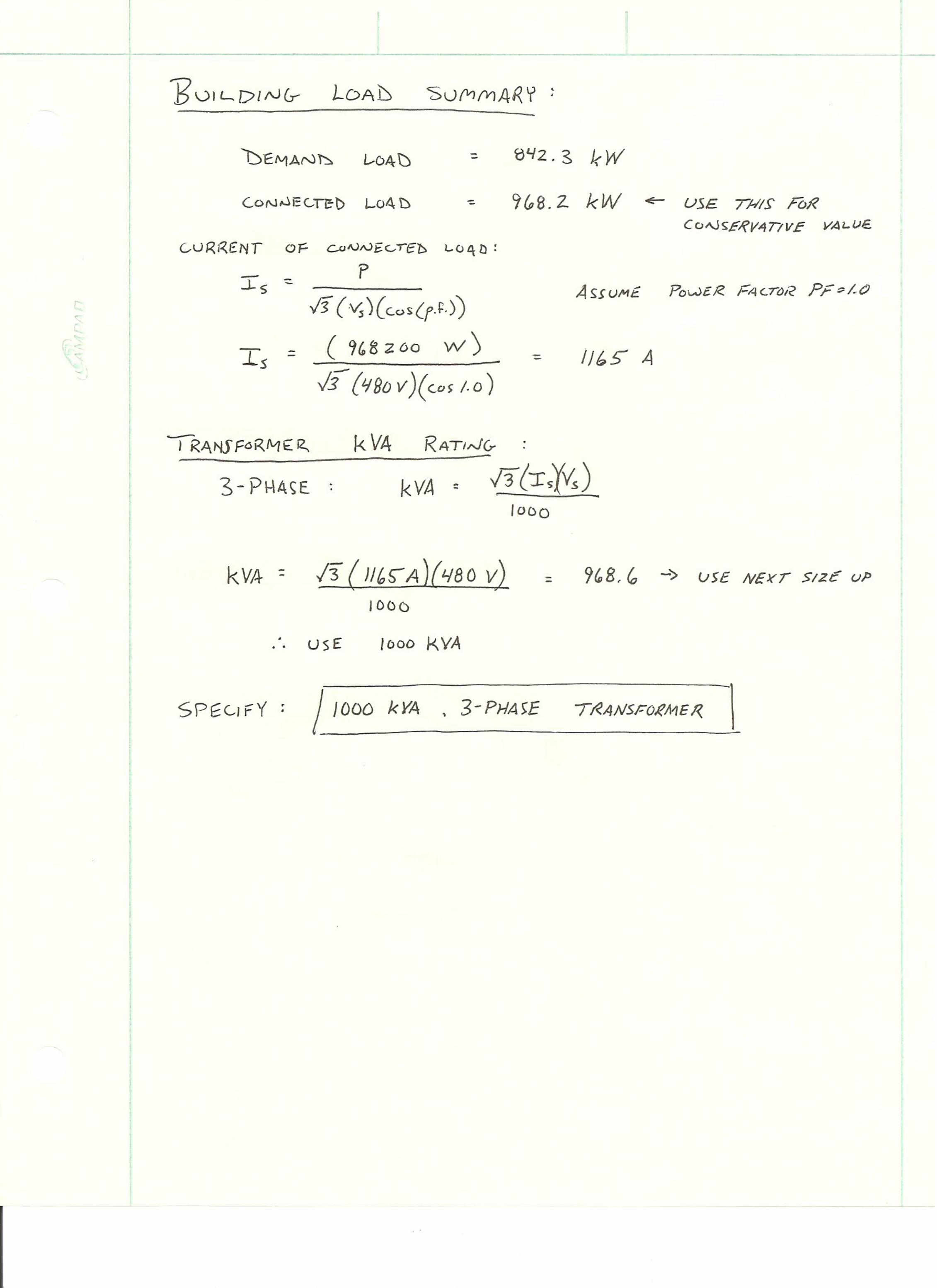
Through the collection of building load estimates and summarizing the electrical load of the building, an electrical calculation could be performed to determine the size of a building transformer to step down the incoming electrical service feed for the Phase 2 New Building. Calculations determined that a 3‐phase exterior building transformer should be expected to be sized at 1000 kVA rating. This differs from the transformer that was installed, but could attribute to sizing factors applied by the utility provider that was not accounted for.
Electrical Breadth Calculations are as follows:
43
Quality Control Issues An outdoor transformer, which is what the Phase 2 New Building requires, offers many advantages over indoor space transformers. The advantages include no building space used and reduced noise within the building. Also, they are generally lower in cost and have an easier maintenance and replacement value because it is located outdoors. However, costs can increase if long voltage runs are required, or if the transformer is exposed to direct sunlight, which increases the temperature and decreases its rating.
After research, it has been determined that standard data should be collected to begin sizing a transformer. It is important to first determine the electrical load, voltage required by load, and if the load is designed to operate on three phase power. Second, it is important to determine the supply voltage or amps. The frequency of the line supply and electrical load must be checked to be the same. A three phase transformer is selected which is designed to operate at the same primary input and supply voltage as the secondary output. The engineer would then need to use calculations to determine the kVA rating based on the known voltage and ampere required. Once the known kVA rating is established, it is important to select a three phase transformer with a standard kVA capacity of equal to or greater than that needed to operate the building loads.
The utility design engineer will normally calculate the anticipated loads for the building using the National Electric Code (NEC). The designer will have to take into account all estimated loads for motors, lighting, receptacles, any purchased equipment by the client, unknown load factors, and load growth factors. With all of these factors in mind, the distribution system becomes oversized. The electrical designer will contact the utility company to determine the location of the transformer and their recommended size based on these anticipated loads.
Coordination of the selection of the transformer and other electrical system devices are becoming very important issues. If the electrical system design engineer and utility company are not on the same page with building load anticipation, then the transformer is typically provided at an incorrect size. This can cause problems with other components in the electrical system and failures can occur.
Best Practices After research, it has been determined that several challenges are faced when dealing with electrical system and building transformers. The life span of the electrical equipment has become an important issue. It is important to make sure that transformers that are installed remain operable and in service for as long as possible. This can mean continuous operation over the lifespan of buildings at full loading. There are a large percentage of installed transformers that stay in service for more than 25 years and the health of these are generally unknown unless regular maintenance occurs and log sheets are kept for the specific piece of equipment.
There are many issues that occur in the insulation of the transformers. Many of the transformer faults that occur are caused by temperature and moisture infiltrating the insulation and cause performance to decline. A healthy transformer means regular maintenance programs need to be adopted to periodically test the performance and maintain the originally designed performance levels.
44
When regular maintenance does occur on a transformer or any other electrical system component, it is important that regular load profiles, locations, and design history is logged. Power factor, percent moisture, and dissolved gas analysis (DGA) are three important measures that should be checked when performing maintenance on a transformer.
The following is a list of tests that should occur on transformers during maintenance or installation testing:
• DGA/Oil Screen
• Power Factors and Capacitance
• Turns Ratio (TTR)
• Leakage Reactance
• Winding Resistance
• Dielectric Frequency Response
• IR
Conclusions and Recommendations Based on the research and information presented in this analysis, quality issues and best practices in terms of building transformers have been determined. Also, calculations have determined that a 1000‐kVA transformer would be appropriate for this project. This differs from the 750 kVA size installed at the Phase 2 New Building, but can be attributed to factors in down‐sizing the transformer size that is typically performed by the electrical power company.
Research has determined that there are important steps and processes that must occur between the electrical design engineer and the power company to properly size the building transfer to eliminate any problems with component failures or incorrect sizing. Additionally, there are many quality control issues associated with controlling the selection of the transformer based on anticipated building loads, supply voltages and frequency. Also, best practices have been determined which can be implemented during the installation checks and maintenance checks of the transformer. Since transformers remain in place for long lifetimes, it is important that they can be expected to perform at their designed performance levels and do not suffer and lost efficiency.
45
Summary and Conclusions Through the completion of the analyses within this thesis report, ways in which the building exterior façade and roofing system can be changed adding to or offering similar quality as the original design were investigated. Additionally, research into sizing the building’s electrical transformer and the quality control issues associated with building transformers was investigated. If the analysis of this report were implemented for the Phase 2 New Building at the John Tyler Community College’s Midlothian Campus, the owner would be provided with unique benefits guaranteeing added quality to the project.
The first analysis investigated the use and implementation of an alternative exterior façade system in place of the hand‐laid brick wall system. This analysis investigated a product known as SlenderWall which is an architectural precast concrete and steel stud panel wall system comprised of an exterior surface of thin architectural brick veneer cast into 2‐inches of high‐strength reinforced architectural precast concrete. The inside of the panel is composed of 16‐gauge, 6‐inch galvanized steel studs vertically spaced at 2‐foot centers. This panel’s construction enables the brick veneer, vapor barrier, exterior sheathing, and exterior metal studs to be removed from the scope of the project.
By replacing the land laid brick veneer system with the SlenderWall precast panel system, the project does not lose the aesthetic quality of the exterior façade if the appropriate architectural brick is selected. Also, $15,883 of upfront cost savings was determined. The SlenderWall system also provides a 16‐day reduction in building skin installation time while minimizing site congestion during the superstructure phase.
The second analysis focused on changing the roofing system to an alternative single‐ply thermoplastic TPO “cool” roof in lieu of the IRMA and green roof system installed. The analysis investigated a roofing contractor’s recommended roofing system produced by Firestone Building Products. The alternative system consisted of 5‐inches of closed‐cell polyisocyanurate insulation fully adhered to the concrete deck providing an R‐30 insulation property. The 60‐mil white UltraPly TPO membrane is then fully adhered to the insulation, providing a continuous waterproofing membrane with exceptional reflective properties.
If the priority of the owner is mainly upfront cost savings, the TPO “cool” roofing system offers an estimated upfront cost savings of $269,300. Additionally, the amount of materials delivered to and stored on site is greatly reduced offering reduced site congestion and reduces the roofing schedule by 10 days. However, the alternative “cool” roofing system would result in an estimated heat transfer increase of 37% summer heat gain and 16% winter heat loss.
Utilizing the green roof and IRMA roofing system instead of the alternative would be a much better option for energy efficiency and adds additional LEED® credits that are not achievable through the alternative “cool” roof. Despite the increase in upfront costs, the green roof system over the IRMA roof has the potential to add 4 to 10 additional LEED® credits, depending on the use and design, as well as creating a “green” public image by incorporating a green roof system.
46
Finally, the third analysis included the research and calculations involved in properly sizing a building transformer based on anticipated building loads. The research and information presented in the analysis determined quality issues and best practices in building transformers. Through calculations, it was determined that a 3‐phase 1000 kVA transformer would be a safe, suitable size for the Phase 2 New Building. This differed from the 750 kVA transformer installed, but can contribute to possible factors in down‐sizing the transformer by the electric power company, which has became normal in the industry. Additionally, there are many quality control issues associated with controlling the selection of the transformer based on anticipated building loads, supply voltages and frequency. Also, best practices have been determined which can be implemented during the installation checks and maintenance checks of the transformer. Since transformers remain in place for long lifetimes, it is important that they can be expected to perform at their designed performance levels and do not suffer and lost efficiency.
Overall, the quality of the project can be increased when incorporating the three analysis topics into the design and construction of the Phase 2 New Building at the John Tyler Community College’s Midlothian Campus. The incorporation and close attention to the alternative systems and the quality control issues presented in each analysis have the potential to decrease cost, add quality, and lighten the schedule and reduce impacts of delays and site congestion.
47
References AISC. Steel Construction Manual. Thirteenth ed. United States of America: American Institute of Steel
Construction, 2005. Print.
"Architectural Precast Concrete." Mid‐Atlantic Precast Association (MAPA). Web. 01 Feb. 2010. <http://www.mapaprecast.org/precast‐arch.asp>.
ASCE. Minimum Design Loads for Buildings and Other Structures. Reston, Va: American Society of Civil Engineers/Structural Engineering Institute, 2006. Print.
"Building Envelope Design Guide ‐ Masonry Wall Systems | Whole Building Design Guide." WBDG ‐ The Whole Building Design Guide. Web. 01 Feb. 2010. <http://www.wbdg.org/design/env_wall_masonry.php>.
"Building Envelope Design Guide ‐ Precast Concrete Wall Systems | Whole Building Design Guide." WBDG ‐ The Whole Building Design Guide. Web. 01 Feb. 2010. <http://www.wbdg.org/design/env_wall_precast_concrete.php>.
"Building Envelope Design Guide ‐ Roofing Systems | Whole Building Design Guide." WBDG ‐ The Whole Building Design Guide. Web. 01 Mar. 2010. <http://www.wbdg.org/design/env_roofing.php>.
"Extensive Green Roofs | Whole Building Design Guide." WBDG ‐ The Whole Building Design Guide. Web. 01 Mar. 2010. <http://www.wbdg.org/resources/greenroofs.php?r=env_roofing>.
Geschwindner, Louis F. Unified Design of Steel Structures. Hoboken, New Jersey: J. Wiley & Sons, 2008. Print.
Hughes, S. David. Electrical Systems in Buildings. Boston: Delmar Pub., 1988. Print.
Kibert, Charles J. Sustainable Construction: Green Building Design and Delivery. Second ed. Hoboken, N.J.: John Wiley & Sons, 2008. Print.
Micco, Drew. "Project Discussion." Telephone interview. 4 Feb. 2010.
Mistrick, Richard G. "Transformer Sizing." 29 Mar. 2010. E‐mail.
Morrison, Gary. Project Manager "Roofing." Telephone interview. 22 Mar. 2010.
Nucor Coroporation. Vulcraft Steel Roof & Floor Deck Catalog. 2008. Web. <http://www.vulcraft.com/catalogs.htm>.
Sheppard, Damon. "Project Design and Quality." Telephone interview. 17 Feb. 2010.
SlenderWall Architectural Precast Concrete and Steel Stud Building Panels. Web. 01 Feb. 2010. <http://www.slenderwall.com/index.shtml>.
48
Stein, Benjamin, John S. Reynolds, Walter T. Grondzik, and Alison G. Kwok. Mechanical and Electrical Equipment for Buildings. Tenth ed. Hoboken, N.J.: Wiley, 2006. Print.
"UltraPly TPO Roofing Systems." Firestone Building Products. Web. 01 Mar. 2010. <http://www.firestonebpco.com/roofing/tpo/ultraplytpo/>.
U.S. Green Building Council. LEED® 2009 for New Construction and Major Renovations. Print.
Young, Wayne. "Masonry Construction." Telephone interview. 15 Feb. 2010.

49
Appendix A: Project Schedule Summary
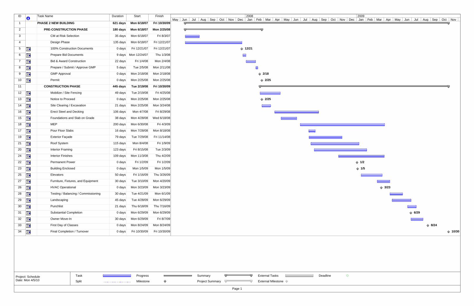
ID Task Name Duration Start Finish
1 PHASE 2 NEW BUILDING 621 days Mon 6/18/07 Fri 10/30/09
2 PRE-CONSTRUCTION PHASE 180 days Mon 6/18/07 Mon 2/25/08
3 CM at Risk Selection 35 days Mon 6/18/07 Fri 8/3/07
4 Design Phase 135 days Mon 6/18/07 Fri 12/21/07
5 100% Construction Documents 0 days Fri 12/21/07 Fri 12/21/07
6 Prepare Bid Documents 9 days Mon 12/24/07 Thu 1/3/08
7 Bid & Award Construction 22 days Fri 1/4/08 Mon 2/4/08
8 Prepare / Submit / Approve GMP 5 days Tue 2/5/08 Mon 2/11/08
9 GMP Approval 0 days Mon 2/18/08 Mon 2/18/08
10 Permit 0 days Mon 2/25/08 Mon 2/25/08
11 CONSTRUCTION PHASE 445 days Tue 2/19/08 Fri 10/30/09
12 Mobilize / Site Fencing 49 days Tue 2/19/08 Fri 4/25/08
13 Notice to Proceed 0 days Mon 2/25/08 Mon 2/25/08
14 Site Clearing / Excavation 21 days Mon 2/25/08 Mon 3/24/08
16 Erect Steel and Decking 106 days Mon 4/7/08 Fri 8/29/08
15 Foundations and Slab on Grade 38 days Mon 4/28/08 Wed 6/18/08
18 MEP 200 days Mon 6/30/08 Fri 4/3/09
17 Pour Floor Slabs 16 days Mon 7/28/08 Mon 8/18/08
19 Exterior Façade 79 days Tue 7/29/08 Fri 11/14/08
21 Roof System 115 days Mon 8/4/08 Fri 1/9/09
20 Interior Framing 123 days Fri 8/15/08 Tue 2/3/09
24 Interior Finishes 109 days Mon 11/3/08 Thu 4/2/09
22 Permanent Power 0 days Fri 1/2/09 Fri 1/2/09
23 Building Enclosed 0 days Mon 1/5/09 Mon 1/5/09
25 Elevators 50 days Fri 1/16/09 Thu 3/26/09
27 Furniture, Fixtures, and Equipment 30 days Tue 3/10/09 Mon 4/20/09
26 HVAC Operational 0 days Mon 3/23/09 Mon 3/23/09
28 Testing / Balancing / Commissioning 30 days Tue 4/21/09 Mon 6/1/09
29 Landscaping 45 days Tue 4/28/09 Mon 6/29/09
30 Punchlist 21 days Thu 6/18/09 Thu 7/16/09
31 Substantial Completion 0 days Mon 6/29/09 Mon 6/29/09
32 Owner Move-In 30 days Mon 6/29/09 Fri 8/7/09
33 First Day of Classes 0 days Mon 8/24/09 Mon 8/24/09
34 Final Completion / Turnover 0 days Fri 10/30/09 Fri 10/30/09
12/21
2/18
2/25
2/25
1/2
1/5
3/23
6/29
8/24
10/30
May Jun Jul Aug Sep Oct Nov Dec Jan Feb Mar Apr May Jun Jul Aug Sep Oct Nov Dec Jan Feb Mar Apr May Jun Jul Aug Sep Oct Nov2008 2009
Task
Split
Progress
Milestone
Summary
Project Summary
External Tasks
External Milestone
Deadline
Page 1
Project: ScheduleDate: Mon 4/5/10

51
Appendix B: Detailed Project Schedule
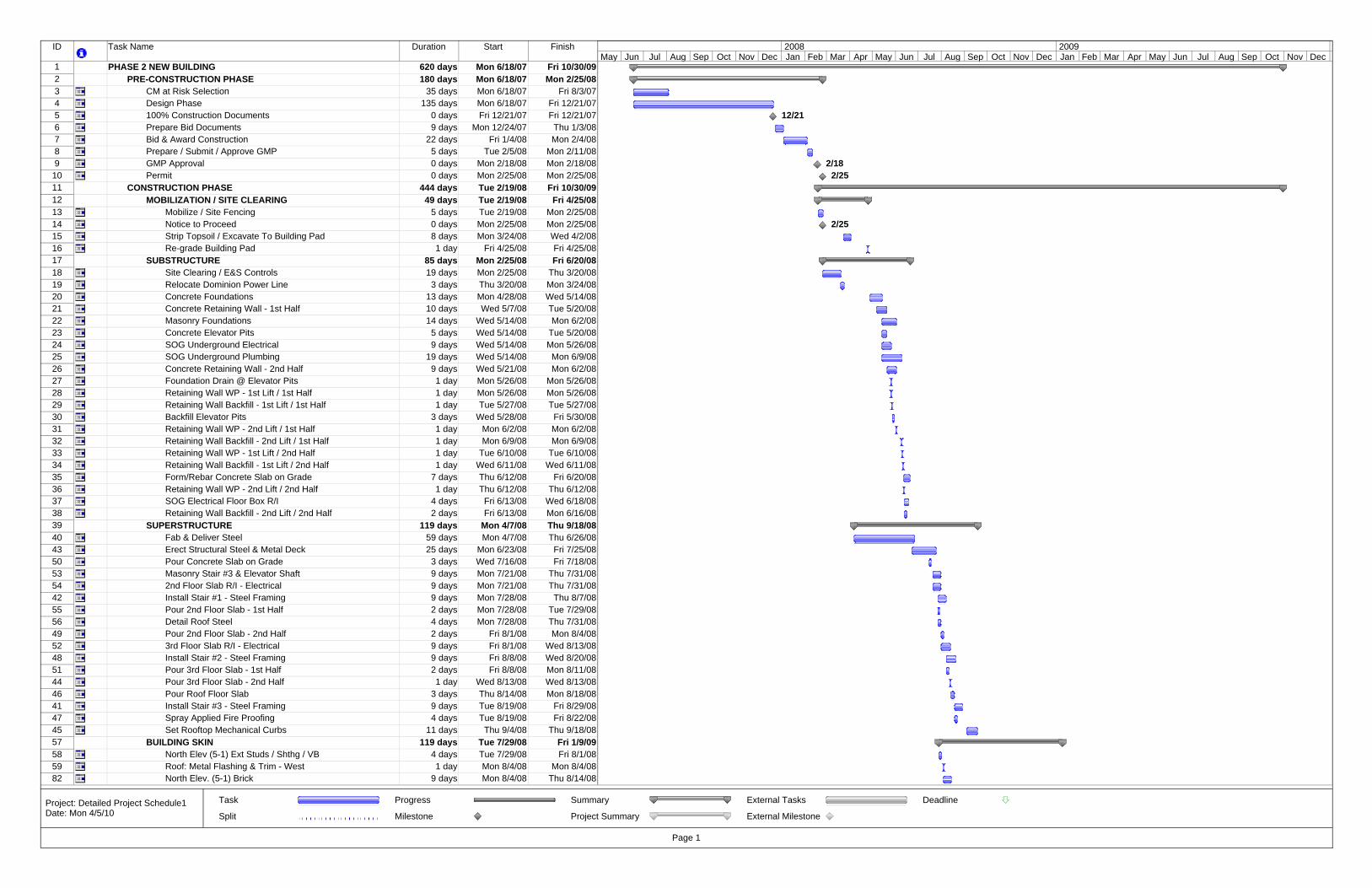
ID Task Name Duration Start Finish
1 PHASE 2 NEW BUILDING 620 days Mon 6/18/07 Fri 10/30/092 PRE-CONSTRUCTION PHASE 180 days Mon 6/18/07 Mon 2/25/083 CM at Risk Selection 35 days Mon 6/18/07 Fri 8/3/074 Design Phase 135 days Mon 6/18/07 Fri 12/21/075 100% Construction Documents 0 days Fri 12/21/07 Fri 12/21/076 Prepare Bid Documents 9 days Mon 12/24/07 Thu 1/3/087 Bid & Award Construction 22 days Fri 1/4/08 Mon 2/4/088 Prepare / Submit / Approve GMP 5 days Tue 2/5/08 Mon 2/11/089 GMP Approval 0 days Mon 2/18/08 Mon 2/18/08
10 Permit 0 days Mon 2/25/08 Mon 2/25/0811 CONSTRUCTION PHASE 444 days Tue 2/19/08 Fri 10/30/0912 MOBILIZATION / SITE CLEARING 49 days Tue 2/19/08 Fri 4/25/0813 Mobilize / Site Fencing 5 days Tue 2/19/08 Mon 2/25/0814 Notice to Proceed 0 days Mon 2/25/08 Mon 2/25/0815 Strip Topsoil / Excavate To Building Pad 8 days Mon 3/24/08 Wed 4/2/0816 Re-grade Building Pad 1 day Fri 4/25/08 Fri 4/25/0817 SUBSTRUCTURE 85 days Mon 2/25/08 Fri 6/20/0818 Site Clearing / E&S Controls 19 days Mon 2/25/08 Thu 3/20/0819 Relocate Dominion Power Line 3 days Thu 3/20/08 Mon 3/24/0820 Concrete Foundations 13 days Mon 4/28/08 Wed 5/14/0821 Concrete Retaining Wall - 1st Half 10 days Wed 5/7/08 Tue 5/20/0822 Masonry Foundations 14 days Wed 5/14/08 Mon 6/2/0823 Concrete Elevator Pits 5 days Wed 5/14/08 Tue 5/20/0824 SOG Underground Electrical 9 days Wed 5/14/08 Mon 5/26/0825 SOG Underground Plumbing 19 days Wed 5/14/08 Mon 6/9/0826 Concrete Retaining Wall - 2nd Half 9 days Wed 5/21/08 Mon 6/2/0827 Foundation Drain @ Elevator Pits 1 day Mon 5/26/08 Mon 5/26/0828 Retaining Wall WP - 1st Lift / 1st Half 1 day Mon 5/26/08 Mon 5/26/0829 Retaining Wall Backfill - 1st Lift / 1st Half 1 day Tue 5/27/08 Tue 5/27/0830 Backfill Elevator Pits 3 days Wed 5/28/08 Fri 5/30/0831 Retaining Wall WP - 2nd Lift / 1st Half 1 day Mon 6/2/08 Mon 6/2/0832 Retaining Wall Backfill - 2nd Lift / 1st Half 1 day Mon 6/9/08 Mon 6/9/0833 Retaining Wall WP - 1st Lift / 2nd Half 1 day Tue 6/10/08 Tue 6/10/0834 Retaining Wall Backfill - 1st Lift / 2nd Half 1 day Wed 6/11/08 Wed 6/11/0835 Form/Rebar Concrete Slab on Grade 7 days Thu 6/12/08 Fri 6/20/0836 Retaining Wall WP - 2nd Lift / 2nd Half 1 day Thu 6/12/08 Thu 6/12/0837 SOG Electrical Floor Box R/I 4 days Fri 6/13/08 Wed 6/18/0838 Retaining Wall Backfill - 2nd Lift / 2nd Half 2 days Fri 6/13/08 Mon 6/16/0839 SUPERSTRUCTURE 119 days Mon 4/7/08 Thu 9/18/0840 Fab & Deliver Steel 59 days Mon 4/7/08 Thu 6/26/0843 Erect Structural Steel & Metal Deck 25 days Mon 6/23/08 Fri 7/25/0850 Pour Concrete Slab on Grade 3 days Wed 7/16/08 Fri 7/18/0853 Masonry Stair #3 & Elevator Shaft 9 days Mon 7/21/08 Thu 7/31/0854 2nd Floor Slab R/I - Electrical 9 days Mon 7/21/08 Thu 7/31/0842 Install Stair #1 - Steel Framing 9 days Mon 7/28/08 Thu 8/7/0855 Pour 2nd Floor Slab - 1st Half 2 days Mon 7/28/08 Tue 7/29/0856 Detail Roof Steel 4 days Mon 7/28/08 Thu 7/31/0849 Pour 2nd Floor Slab - 2nd Half 2 days Fri 8/1/08 Mon 8/4/0852 3rd Floor Slab R/I - Electrical 9 days Fri 8/1/08 Wed 8/13/0848 Install Stair #2 - Steel Framing 9 days Fri 8/8/08 Wed 8/20/0851 Pour 3rd Floor Slab - 1st Half 2 days Fri 8/8/08 Mon 8/11/0844 Pour 3rd Floor Slab - 2nd Half 1 day Wed 8/13/08 Wed 8/13/0846 Pour Roof Floor Slab 3 days Thu 8/14/08 Mon 8/18/0841 Install Stair #3 - Steel Framing 9 days Tue 8/19/08 Fri 8/29/0847 Spray Applied Fire Proofing 4 days Tue 8/19/08 Fri 8/22/0845 Set Rooftop Mechanical Curbs 11 days Thu 9/4/08 Thu 9/18/0857 BUILDING SKIN 119 days Tue 7/29/08 Fri 1/9/0958 North Elev (5-1) Ext Studs / Shthg / VB 4 days Tue 7/29/08 Fri 8/1/0859 Roof: Metal Flashing & Trim - West 1 day Mon 8/4/08 Mon 8/4/0882 North Elev. (5-1) Brick 9 days Mon 8/4/08 Thu 8/14/08
12/21
2/182/25
2/25
May Jun Jul Aug Sep Oct Nov Dec Jan Feb Mar Apr May Jun Jul Aug Sep Oct Nov Dec Jan Feb Mar Apr May Jun Jul Aug Sep Oct Nov Dec2008 2009
Task
Split
Progress
Milestone
Summary
Project Summary
External Tasks
External Milestone
Deadline
Page 1
Project: Detailed Project Schedule1Date: Mon 4/5/10
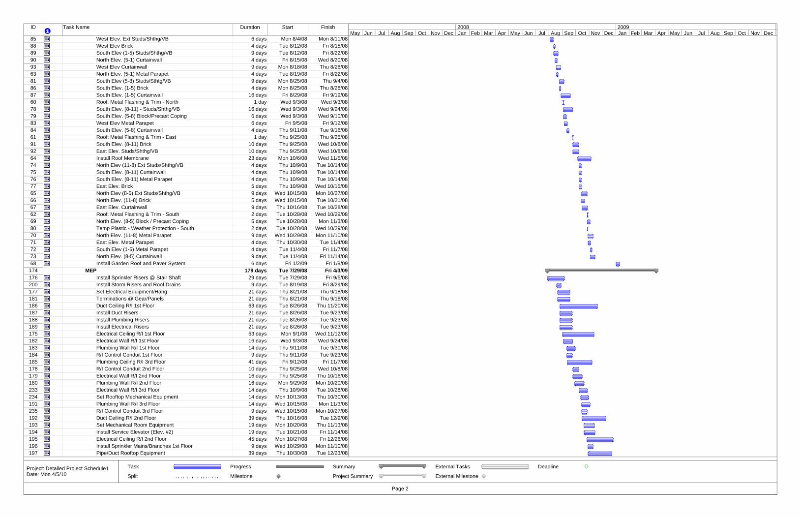
ID Task Name Duration Start Finish
85 West Elev. Ext Studs/Shthg/VB 6 days Mon 8/4/08 Mon 8/11/0888 West Elev Brick 4 days Tue 8/12/08 Fri 8/15/0889 South Elev (1-5) Studs/Shthg/VB 9 days Tue 8/12/08 Fri 8/22/0890 North Elev. (5-1) Curtainwall 4 days Fri 8/15/08 Wed 8/20/0893 West Elev Curtainwall 9 days Mon 8/18/08 Thu 8/28/0863 North Elev. (5-1) Metal Parapet 4 days Tue 8/19/08 Fri 8/22/0881 South Elev (5-8) Studs/Sthtg/VB 9 days Mon 8/25/08 Thu 9/4/0886 South Elev. (1-5) Brick 4 days Mon 8/25/08 Thu 8/28/0887 South Elev. (1-5) Curtainwall 16 days Fri 8/29/08 Fri 9/19/0860 Roof: Metal Flashing & Trim - North 1 day Wed 9/3/08 Wed 9/3/0878 South Elev. (8-11) - Studs/Shthg/VB 16 days Wed 9/3/08 Wed 9/24/0879 South Elev. (5-8) Block/Precast Coping 6 days Wed 9/3/08 Wed 9/10/0883 West Elev Metal Parapet 6 days Fri 9/5/08 Fri 9/12/0884 South Elev. (5-8) Curtainwall 4 days Thu 9/11/08 Tue 9/16/0861 Roof: Metal Flashing & Trim - East 1 day Thu 9/25/08 Thu 9/25/0891 South Elev. (8-11) Brick 10 days Thu 9/25/08 Wed 10/8/0892 East Elev. Studs/Shthg/VB 10 days Thu 9/25/08 Wed 10/8/0864 Install Roof Membrane 23 days Mon 10/6/08 Wed 11/5/0874 North Elev (11-8) Ext Studs/Shthg/VB 4 days Thu 10/9/08 Tue 10/14/0875 South Elev. (8-11) Curtainwall 4 days Thu 10/9/08 Tue 10/14/0876 South Elev. (8-11) Metal Parapet 4 days Thu 10/9/08 Tue 10/14/0877 East Elev. Brick 5 days Thu 10/9/08 Wed 10/15/0865 North Elev (8-5) Ext Studs/Shthg/VB 9 days Wed 10/15/08 Mon 10/27/0866 North Elev. (11-8) Brick 5 days Wed 10/15/08 Tue 10/21/0867 East Elev. Curtainwall 9 days Thu 10/16/08 Tue 10/28/0862 Roof: Metal Flashing & Trim - South 2 days Tue 10/28/08 Wed 10/29/0869 North Elev. (8-5) Block / Precast Coping 5 days Tue 10/28/08 Mon 11/3/0880 Temp Plastic - Weather Protection - South 2 days Tue 10/28/08 Wed 10/29/0870 North Elev. (11-8) Metal Parapet 9 days Wed 10/29/08 Mon 11/10/0871 East Elev. Metal Parapet 4 days Thu 10/30/08 Tue 11/4/0872 South Elev (1-5) Metal Parapet 4 days Tue 11/4/08 Fri 11/7/0873 North Elev. (8-5) Curtainwall 9 days Tue 11/4/08 Fri 11/14/0868 Install Garden Roof and Paver System 6 days Fri 1/2/09 Fri 1/9/09
174 MEP 179 days Tue 7/29/08 Fri 4/3/09176 Install Sprinkler Risers @ Stair Shaft 29 days Tue 7/29/08 Fri 9/5/08200 Install Storm Risers and Roof Drains 9 days Tue 8/19/08 Fri 8/29/08177 Set Electrical Equipment/Hang 21 days Thu 8/21/08 Thu 9/18/08181 Terminations @ Gear/Panels 21 days Thu 8/21/08 Thu 9/18/08186 Duct Ceiling R/I 1st Floor 63 days Tue 8/26/08 Thu 11/20/08187 Install Duct Risers 21 days Tue 8/26/08 Tue 9/23/08188 Install Plumbing Risers 21 days Tue 8/26/08 Tue 9/23/08189 Install Electrical Risers 21 days Tue 8/26/08 Tue 9/23/08175 Electrical Ceiling R/I 1st Floor 53 days Mon 9/1/08 Wed 11/12/08182 Electrical Wall R/I 1st Floor 16 days Wed 9/3/08 Wed 9/24/08183 Plumbing Wall R/I 1st Floor 14 days Thu 9/11/08 Tue 9/30/08184 R/I Control Conduit 1st Floor 9 days Thu 9/11/08 Tue 9/23/08185 Plumbing Ceiling R/I 3rd Floor 41 days Fri 9/12/08 Fri 11/7/08178 R/I Control Conduit 2nd Floor 10 days Thu 9/25/08 Wed 10/8/08179 Electrical Wall R/I 2nd Floor 16 days Thu 9/25/08 Thu 10/16/08180 Plumbing Wall R/I 2nd Floor 16 days Mon 9/29/08 Mon 10/20/08233 Electrical Wall R/I 3rd Floor 14 days Thu 10/9/08 Tue 10/28/08234 Set Rooftop Mechanical Equipment 14 days Mon 10/13/08 Thu 10/30/08191 Plumbing Wall R/I 3rd Floor 14 days Wed 10/15/08 Mon 11/3/08235 R/I Control Conduit 3rd Floor 9 days Wed 10/15/08 Mon 10/27/08192 Duct Ceiling R/I 2nd Floor 39 days Thu 10/16/08 Tue 12/9/08193 Set Mechanical Room Equipment 19 days Mon 10/20/08 Thu 11/13/08194 Install Service Elevator (Elev. #2) 19 days Tue 10/21/08 Fri 11/14/08195 Electrical Ceiling R/I 2nd Floor 45 days Mon 10/27/08 Fri 12/26/08196 Install Sprinkler Mains/Branches 1st Floor 9 days Wed 10/29/08 Mon 11/10/08197 Pipe/Duct Rooftop Equipment 39 days Thu 10/30/08 Tue 12/23/08
May Jun Jul Aug Sep Oct Nov Dec Jan Feb Mar Apr May Jun Jul Aug Sep Oct Nov Dec Jan Feb Mar Apr May Jun Jul Aug Sep Oct Nov Dec2008 2009
Task
Split
Progress
Milestone
Summary
Project Summary
External Tasks
External Milestone
Deadline
Page 2
Project: Detailed Project Schedule1Date: Mon 4/5/10
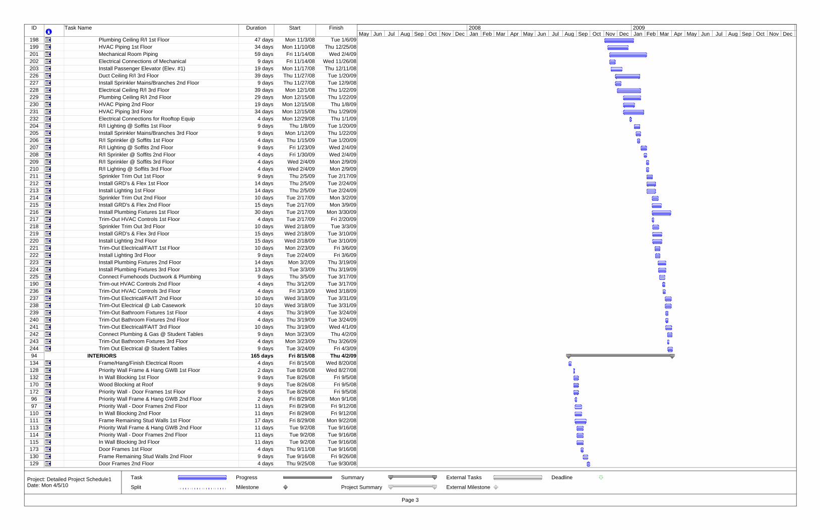
ID Task Name Duration Start Finish
198 Plumbing Ceiling R/I 1st Floor 47 days Mon 11/3/08 Tue 1/6/09199 HVAC Piping 1st Floor 34 days Mon 11/10/08 Thu 12/25/08201 Mechanical Room Piping 59 days Fri 11/14/08 Wed 2/4/09202 Electrical Connections of Mechanical 9 days Fri 11/14/08 Wed 11/26/08203 Install Passenger Elevator (Elev. #1) 19 days Mon 11/17/08 Thu 12/11/08226 Duct Ceiling R/I 3rd Floor 39 days Thu 11/27/08 Tue 1/20/09227 Install Sprinkler Mains/Branches 2nd Floor 9 days Thu 11/27/08 Tue 12/9/08228 Electrical Ceiling R/I 3rd Floor 39 days Mon 12/1/08 Thu 1/22/09229 Plumbing Ceiling R/I 2nd Floor 29 days Mon 12/15/08 Thu 1/22/09230 HVAC Piping 2nd Floor 19 days Mon 12/15/08 Thu 1/8/09231 HVAC Piping 3rd Floor 34 days Mon 12/15/08 Thu 1/29/09232 Electrical Connections for Rooftop Equip 4 days Mon 12/29/08 Thu 1/1/09204 R/I Lighting @ Soffits 1st Floor 9 days Thu 1/8/09 Tue 1/20/09205 Install Sprinkler Mains/Branches 3rd Floor 9 days Mon 1/12/09 Thu 1/22/09206 R/I Sprinkler @ Soffits 1st Floor 4 days Thu 1/15/09 Tue 1/20/09207 R/I Lighting @ Soffits 2nd Floor 9 days Fri 1/23/09 Wed 2/4/09208 R/I Sprinkler @ Soffits 2nd Floor 4 days Fri 1/30/09 Wed 2/4/09209 R/I Sprinkler @ Soffits 3rd Floor 4 days Wed 2/4/09 Mon 2/9/09210 R/I Lighting @ Soffits 3rd Floor 4 days Wed 2/4/09 Mon 2/9/09211 Sprinkler Trim Out 1st Floor 9 days Thu 2/5/09 Tue 2/17/09212 Install GRD's & Flex 1st Floor 14 days Thu 2/5/09 Tue 2/24/09213 Install Lighting 1st Floor 14 days Thu 2/5/09 Tue 2/24/09214 Sprinkler Trim Out 2nd Floor 10 days Tue 2/17/09 Mon 3/2/09215 Install GRD's & Flex 2nd Floor 15 days Tue 2/17/09 Mon 3/9/09216 Install Plumbing Fixtures 1st Floor 30 days Tue 2/17/09 Mon 3/30/09217 Trim-Out HVAC Controls 1st Floor 4 days Tue 2/17/09 Fri 2/20/09218 Sprinkler Trim Out 3rd Floor 10 days Wed 2/18/09 Tue 3/3/09219 Install GRD's & Flex 3rd Floor 15 days Wed 2/18/09 Tue 3/10/09220 Install Lighting 2nd Floor 15 days Wed 2/18/09 Tue 3/10/09221 Trim-Out Electrical/FA/IT 1st Floor 10 days Mon 2/23/09 Fri 3/6/09222 Install Lighting 3rd Floor 9 days Tue 2/24/09 Fri 3/6/09223 Install Plumbing Fixtures 2nd Floor 14 days Mon 3/2/09 Thu 3/19/09224 Install Plumbing Fixtures 3rd Floor 13 days Tue 3/3/09 Thu 3/19/09225 Connect Fumehoods Ductwork & Plumbing 9 days Thu 3/5/09 Tue 3/17/09190 Trim-out HVAC Controls 2nd Floor 4 days Thu 3/12/09 Tue 3/17/09236 Trim-Out HVAC Controls 3rd Floor 4 days Fri 3/13/09 Wed 3/18/09237 Trim-Out Electrical/FA/IT 2nd Floor 10 days Wed 3/18/09 Tue 3/31/09238 Trim-Out Electrical @ Lab Casework 10 days Wed 3/18/09 Tue 3/31/09239 Trim-Out Bathroom Fixtures 1st Floor 4 days Thu 3/19/09 Tue 3/24/09240 Trim-Out Bathroom Fixtures 2nd Floor 4 days Thu 3/19/09 Tue 3/24/09241 Trim-Out Electrical/FA/IT 3rd Floor 10 days Thu 3/19/09 Wed 4/1/09242 Connect Plumbing & Gas @ Student Tables 9 days Mon 3/23/09 Thu 4/2/09243 Trim-Out Bathroom Fixtures 3rd Floor 4 days Mon 3/23/09 Thu 3/26/09244 Trim Out Electrical @ Student Tables 9 days Tue 3/24/09 Fri 4/3/0994 INTERIORS 165 days Fri 8/15/08 Thu 4/2/09
134 Frame/Hang/Finish Electrical Room 4 days Fri 8/15/08 Wed 8/20/08128 Priority Wall Frame & Hang GWB 1st Floor 2 days Tue 8/26/08 Wed 8/27/08132 In Wall Blocking 1st Floor 9 days Tue 8/26/08 Fri 9/5/08170 Wood Blocking at Roof 9 days Tue 8/26/08 Fri 9/5/08172 Priority Wall - Door Frames 1st Floor 9 days Tue 8/26/08 Fri 9/5/0896 Priority Wall Frame & Hang GWB 2nd Floor 2 days Fri 8/29/08 Mon 9/1/0897 Priority Wall - Door Frames 2nd Floor 11 days Fri 8/29/08 Fri 9/12/08
110 In Wall Blocking 2nd Floor 11 days Fri 8/29/08 Fri 9/12/08111 Frame Remaining Stud Walls 1st Floor 17 days Fri 8/29/08 Mon 9/22/08113 Priority Wall Frame & Hang GWB 2nd Floor 11 days Tue 9/2/08 Tue 9/16/08114 Priority Wall - Door Frames 2nd Floor 11 days Tue 9/2/08 Tue 9/16/08115 In Wall Blocking 3rd Floor 11 days Tue 9/2/08 Tue 9/16/08173 Door Frames 1st Floor 4 days Thu 9/11/08 Tue 9/16/08130 Frame Remaining Stud Walls 2nd Floor 9 days Tue 9/16/08 Fri 9/26/08129 Door Frames 2nd Floor 4 days Thu 9/25/08 Tue 9/30/08
May Jun Jul Aug Sep Oct Nov Dec Jan Feb Mar Apr May Jun Jul Aug Sep Oct Nov Dec Jan Feb Mar Apr May Jun Jul Aug Sep Oct Nov Dec2008 2009
Task
Split
Progress
Milestone
Summary
Project Summary
External Tasks
External Milestone
Deadline
Page 3
Project: Detailed Project Schedule1Date: Mon 4/5/10
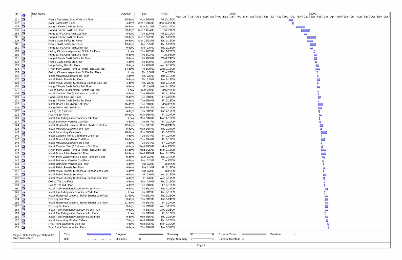
ID Task Name Duration Start Finish
131 Frame Remaining Stud Walls 3rd Floor 15 days Mon 9/29/08 Fri 10/17/08137 Door Frames 3rd Floor 4 days Wed 10/15/08 Mon 10/20/08135 Hang & Finish GWB 1st Floor 29 days Mon 11/3/08 Thu 12/11/08136 Hang & Finish GWB 2nd Floor 29 days Mon 11/24/08 Thu 1/1/09158 Prime & First Coat Paint 1st Floor 9 days Tue 12/9/08 Fri 12/19/0898 Hang & Finish GWB 3rd Floor 29 days Mon 12/22/08 Thu 1/29/09109 Frame GWB Soffits 1st Floor 19 days Mon 12/22/08 Thu 1/15/0999 Frame GWB Soffits 2nd Floor 19 days Mon 1/5/09 Thu 1/29/09161 Prime & First Coat Paint 2nd Floor 9 days Mon 1/5/09 Thu 1/15/09100 Ceiling Close-In Inspection - Soffits 1st Floor 1 day Thu 1/22/09 Thu 1/22/09160 Prime & First Coat Paint 3rd Floor 9 days Thu 1/22/09 Tue 2/3/09101 Hang & Finish GWB Soffits 1st Floor 9 days Fri 1/23/09 Wed 2/4/09102 Frame GWB Soffits 3rd Floor 4 days Thu 1/29/09 Tue 2/3/09103 Hang Ceiling Grid 1st Floor 9 days Fri 1/30/09 Wed 2/11/09104 Finish Paint Walls/ Prime & Finish Paint 1st Floor 14 days Fri 1/30/09 Wed 2/18/09105 Ceiling Close-In Inspection - Soffits 2nd Floor 1 day Thu 2/5/09 Thu 2/5/09106 Install Millwork/Casework 1st Floor 4 days Thu 2/5/09 Tue 2/10/09107 Install Fabric Panels 1st Floor 9 days Thu 2/5/09 Tue 2/17/09108 Install Visual Display Surfaces & Signage 1st Floor 4 days Thu 2/5/09 Tue 2/10/09120 Hang & Finish GWB Soffits 2nd Floor 9 days Fri 2/6/09 Wed 2/18/09171 Ceiling Close-In Inspection - Soffits 3rd Floor 1 day Mon 2/9/09 Mon 2/9/09116 Install Ceramic Tile @ Bathrooms 1st Floor 4 days Tue 2/10/09 Fri 2/13/09119 Hang Ceiling Grid 2nd Floor 9 days Tue 2/10/09 Fri 2/20/09121 Hang & Finish GWB Soffits 3rd Floor 4 days Tue 2/10/09 Fri 2/13/09157 Install Doors & Hardware 1st Floor 15 days Tue 2/10/09 Mon 3/2/09118 Hang Ceiling Grid 3rd Floor 10 days Wed 2/11/09 Tue 2/24/09112 Ceiling Tile 1st Floor 4 days Thu 2/12/09 Tue 2/17/09122 Flooring 1st Floor 10 days Mon 2/16/09 Fri 2/27/09123 Install Fire Extinguisher Cabinets 1st Floor 1 day Mon 2/16/09 Mon 2/16/09117 Install Bathroom Vanities 1st Floor 4 days Tue 2/17/09 Fri 2/20/09124 Install Horizontal Louvers / Roller Shades 1st Floor 12 days Tue 2/17/09 Wed 3/4/09125 Install Millwork/Casework 2nd Floor 5 days Wed 2/18/09 Tue 2/24/09149 Install Laboratory Casework 20 days Mon 2/23/09 Fri 3/20/09146 Install Ceramic Tile @ Bathrooms 2nd Floor 4 days Tue 2/24/09 Fri 2/27/09147 Install Doors & Hardware 2nd Floor 14 days Tue 2/24/09 Fri 3/13/09148 Install Millwork/Casework 3rd Floor 4 days Tue 2/24/09 Fri 2/27/09143 Install Ceramic Tile @ Bathrooms 3rd Floor 4 days Wed 2/25/09 Mon 3/2/09144 Finish Paint Walls/ Prime & Finish Paint 2nd Floor 14 days Wed 2/25/09 Mon 3/16/09145 Install Doors & Hardware 3rd Floor 14 days Wed 2/25/09 Mon 3/16/09138 Finish Paint Walls/Prime & Finish Paint 3rd Floor 9 days Mon 3/2/09 Thu 3/12/09142 Install Bathroom Vanities 2nd Floor 4 days Mon 3/2/09 Thu 3/5/09139 Install Bathroom Vanities 3rd Floor 4 days Tue 3/3/09 Fri 3/6/09140 Install Fabric Panels 2nd Floor 9 days Tue 3/3/09 Fri 3/13/09141 Install Visual Display Surfaces & Signage 2nd Floor 4 days Tue 3/3/09 Fri 3/6/09151 Install Fabric Panels 3rd Floor 9 days Fri 3/6/09 Wed 3/18/09152 Install Visual Display Surfaces & Signage 3rd Floor 4 days Fri 3/6/09 Wed 3/11/09150 Ceiling Tile 2nd Floor 4 days Mon 3/9/09 Thu 3/12/09153 Ceiling Tile 3rd Floor 4 days Tue 3/10/09 Fri 3/13/0995 Install Toilet Partitions/Accessories 1st Floor 9 days Thu 3/12/09 Tue 3/24/09
126 Install Fire Extinguisher Cabinets 2nd Floor 1 day Thu 3/12/09 Thu 3/12/09127 Install Horizontal Louvers / Roller Shades 2nd Floor 11 days Thu 3/12/09 Thu 3/26/09154 Flooring 2nd Floor 9 days Thu 3/12/09 Tue 3/24/09155 Install Horizontal Louvers / Roller Shades 3rd Floor 11 days Fri 3/13/09 Fri 3/27/09167 Flooring 3rd Floor 9 days Fri 3/13/09 Wed 3/25/09168 Install Toilet Partitions/Accessories 2nd Floor 9 days Fri 3/13/09 Wed 3/25/09169 Install Fire Extinguisher Cabinets 3rd Floor 1 day Fri 3/13/09 Fri 3/13/09156 Install Toilet Partitions/Accessories 3rd Floor 9 days Mon 3/16/09 Thu 3/26/09162 Install Laboratory Student Tables 7 days Wed 3/18/09 Thu 3/26/09133 Final Paint Bathrooms 1st Floor 4 days Wed 3/25/09 Mon 3/30/09159 Final Paint Bathrooms 2nd Floor 4 days Thu 3/26/09 Tue 3/31/09
May Jun Jul Aug Sep Oct Nov Dec Jan Feb Mar Apr May Jun Jul Aug Sep Oct Nov Dec Jan Feb Mar Apr May Jun Jul Aug Sep Oct Nov Dec2008 2009
Task
Split
Progress
Milestone
Summary
Project Summary
External Tasks
External Milestone
Deadline
Page 4
Project: Detailed Project Schedule1Date: Mon 4/5/10
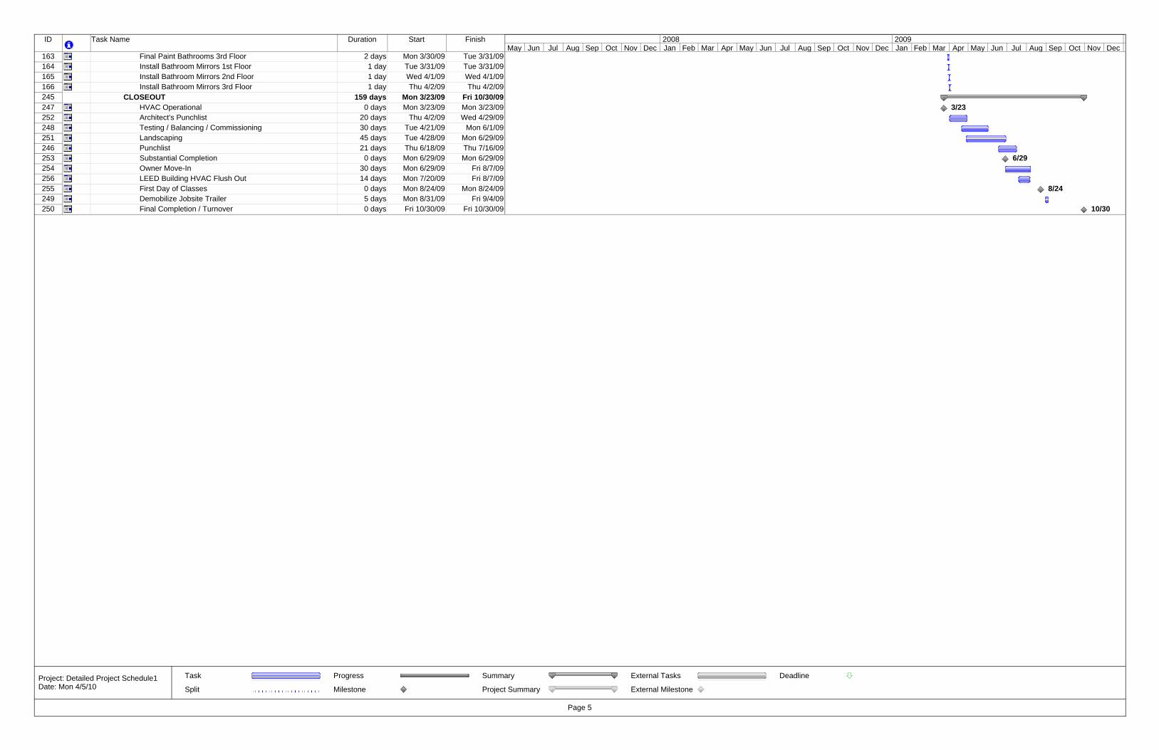
ID Task Name Duration Start Finish
163 Final Paint Bathrooms 3rd Floor 2 days Mon 3/30/09 Tue 3/31/09164 Install Bathroom Mirrors 1st Floor 1 day Tue 3/31/09 Tue 3/31/09165 Install Bathroom Mirrors 2nd Floor 1 day Wed 4/1/09 Wed 4/1/09166 Install Bathroom Mirrors 3rd Floor 1 day Thu 4/2/09 Thu 4/2/09245 CLOSEOUT 159 days Mon 3/23/09 Fri 10/30/09247 HVAC Operational 0 days Mon 3/23/09 Mon 3/23/09252 Architect's Punchlist 20 days Thu 4/2/09 Wed 4/29/09248 Testing / Balancing / Commissioning 30 days Tue 4/21/09 Mon 6/1/09251 Landscaping 45 days Tue 4/28/09 Mon 6/29/09246 Punchlist 21 days Thu 6/18/09 Thu 7/16/09253 Substantial Completion 0 days Mon 6/29/09 Mon 6/29/09254 Owner Move-In 30 days Mon 6/29/09 Fri 8/7/09256 LEED Building HVAC Flush Out 14 days Mon 7/20/09 Fri 8/7/09255 First Day of Classes 0 days Mon 8/24/09 Mon 8/24/09249 Demobilize Jobsite Trailer 5 days Mon 8/31/09 Fri 9/4/09250 Final Completion / Turnover 0 days Fri 10/30/09 Fri 10/30/09
3/23
6/29
8/24
10/30
May Jun Jul Aug Sep Oct Nov Dec Jan Feb Mar Apr May Jun Jul Aug Sep Oct Nov Dec Jan Feb Mar Apr May Jun Jul Aug Sep Oct Nov Dec2008 2009
Task
Split
Progress
Milestone
Summary
Project Summary
External Tasks
External Milestone
Deadline
Page 5
Project: Detailed Project Schedule1Date: Mon 4/5/10

57
Appendix C: Precast Panel Takeoffs
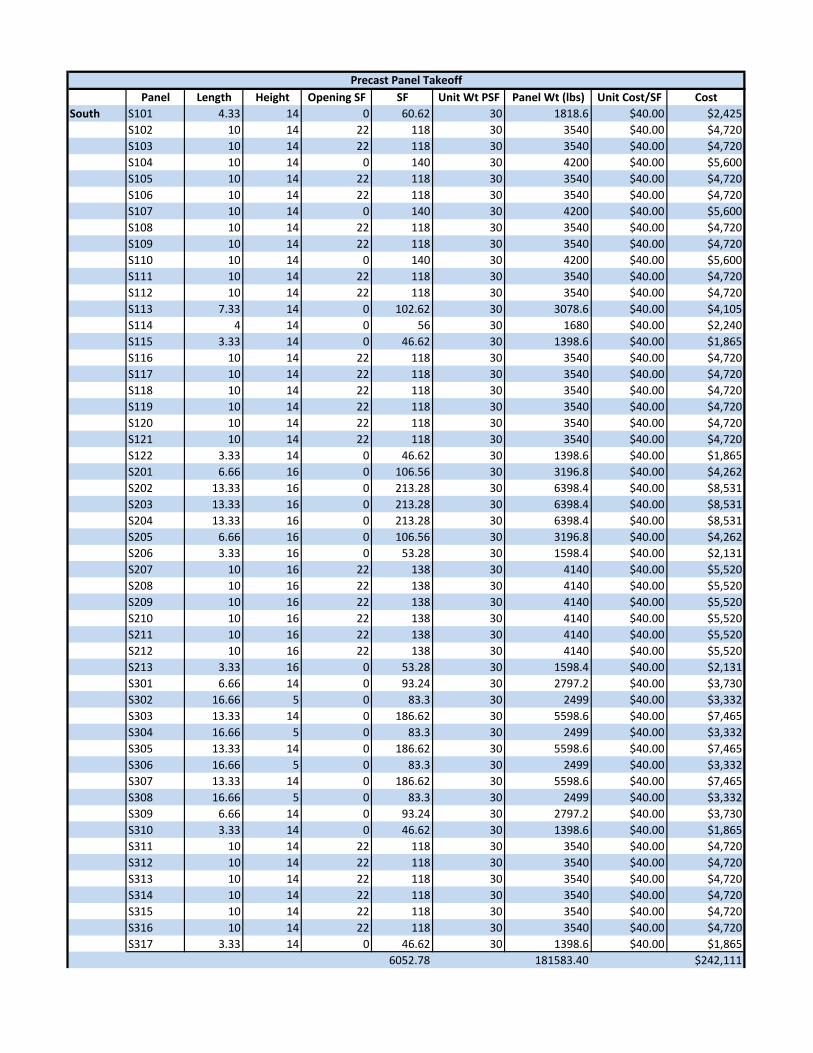
Panel Length Height Opening SF SF Unit Wt PSF Panel Wt (lbs) Unit Cost/SF CostSouth S101 4.33 14 0 60.62 30 1818.6 $40.00 $2,425
S102 10 14 22 118 30 3540 $40.00 $4,720S103 10 14 22 118 30 3540 $40.00 $4,720S104 10 14 0 140 30 4200 $40.00 $5,600S105 10 14 22 118 30 3540 $40.00 $4,720S106 10 14 22 118 30 3540 $40.00 $4,720S107 10 14 0 140 30 4200 $40.00 $5,600S108 10 14 22 118 30 3540 $40.00 $4,720S109 10 14 22 118 30 3540 $40.00 $4,720S110 10 14 0 140 30 4200 $40.00 $5,600S111 10 14 22 118 30 3540 $40.00 $4,720S112 10 14 22 118 30 3540 $40.00 $4,720S113 7.33 14 0 102.62 30 3078.6 $40.00 $4,105S114 4 14 0 56 30 1680 $40.00 $2,240S115 3.33 14 0 46.62 30 1398.6 $40.00 $1,865S116 10 14 22 118 30 3540 $40.00 $4,720S117 10 14 22 118 30 3540 $40.00 $4,720S118 10 14 22 118 30 3540 $40.00 $4,720S119 10 14 22 118 30 3540 $40.00 $4,720S120 10 14 22 118 30 3540 $40.00 $4,720S121 10 14 22 118 30 3540 $40.00 $4,720S122 3.33 14 0 46.62 30 1398.6 $40.00 $1,865S201 6.66 16 0 106.56 30 3196.8 $40.00 $4,262S202 13.33 16 0 213.28 30 6398.4 $40.00 $8,531S203 13.33 16 0 213.28 30 6398.4 $40.00 $8,531S204 13.33 16 0 213.28 30 6398.4 $40.00 $8,531S205 6.66 16 0 106.56 30 3196.8 $40.00 $4,262S206 3.33 16 0 53.28 30 1598.4 $40.00 $2,131S207 10 16 22 138 30 4140 $40.00 $5,520S208 10 16 22 138 30 4140 $40.00 $5,520S209 10 16 22 138 30 4140 $40.00 $5,520S210 10 16 22 138 30 4140 $40.00 $5,520S211 10 16 22 138 30 4140 $40.00 $5,520S212 10 16 22 138 30 4140 $40.00 $5,520S213 3.33 16 0 53.28 30 1598.4 $40.00 $2,131S301 6.66 14 0 93.24 30 2797.2 $40.00 $3,730S302 16.66 5 0 83.3 30 2499 $40.00 $3,332S303 13.33 14 0 186.62 30 5598.6 $40.00 $7,465S304 16.66 5 0 83.3 30 2499 $40.00 $3,332S305 13.33 14 0 186.62 30 5598.6 $40.00 $7,465S306 16.66 5 0 83.3 30 2499 $40.00 $3,332S307 13.33 14 0 186.62 30 5598.6 $40.00 $7,465S308 16.66 5 0 83.3 30 2499 $40.00 $3,332S309 6.66 14 0 93.24 30 2797.2 $40.00 $3,730S310 3.33 14 0 46.62 30 1398.6 $40.00 $1,865S311 10 14 22 118 30 3540 $40.00 $4,720S312 10 14 22 118 30 3540 $40.00 $4,720S313 10 14 22 118 30 3540 $40.00 $4,720S314 10 14 22 118 30 3540 $40.00 $4,720S315 10 14 22 118 30 3540 $40.00 $4,720S316 10 14 22 118 30 3540 $40.00 $4,720S317 3.33 14 0 46.62 30 1398.6 $40.00 $1,865
6052.78 181583.40 $242,111
Precast Panel Takeoff
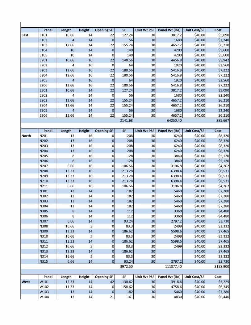
Panel Length Height Opening SF SF Unit Wt PSF Panel Wt (lbs) Unit Cost/SF CostEast E101 10.66 14 22 127.24 30 3817.2 $40.00 $5,090
E102 4 14 0 56 30 1680 $40.00 $2,240E103 12.66 14 22 155.24 30 4657.2 $40.00 $6,210E104 10 14 0 140 30 4200 $40.00 $5,600E105 10 14 0 140 30 4200 $40.00 $5,600E201 10.66 16 22 148.56 30 4456.8 $40.00 $5,942E202 4 16 0 64 30 1920 $40.00 $2,560E203 12.66 16 22 180.56 30 5416.8 $40.00 $7,222E204 12.66 16 22 180.56 30 5416.8 $40.00 $7,222E205 4 16 0 64 30 1920 $40.00 $2,560E206 12.66 16 22 180.56 30 5416.8 $40.00 $7,222E301 10.66 14 22 127.24 30 3817.2 $40.00 $5,090E302 4 14 0 56 30 1680 $40.00 $2,240E303 12.66 14 22 155.24 30 4657.2 $40.00 $6,210E304 12.66 14 22 155.24 30 4657.2 $40.00 $6,210E305 4 14 0 56 30 1680 $40.00 $2,240E306 12.66 14 22 155.24 30 4657.2 $40.00 $6,210
2141.68 64250.40 $85,667
Panel Length Height Opening SF SF Unit Wt PSF Panel Wt (lbs) Unit Cost/SF CostNorth N201 13 16 0 208 30 6240 $40.00 $8,320
N202 13 16 0 208 30 6240 $40.00 $8,320N203 13 16 0 208 30 6240 $40.00 $8,320N204 13 16 0 208 30 6240 $40.00 $8,320N205 8 16 0 128 30 3840 $40.00 $5,120N206 8 16 0 128 30 3840 $40.00 $5,120N207 6.66 16 0 106.56 30 3196.8 $40.00 $4,262N208 13.33 16 0 213.28 30 6398.4 $40.00 $8,531N209 13.33 16 0 213.28 30 6398.4 $40.00 $8,531N210 13.33 16 0 213.28 30 6398.4 $40.00 $8,531N211 6.66 16 0 106.56 30 3196.8 $40.00 $4,262N301 13 14 0 182 30 5460 $40.00 $7,280N302 13 14 0 182 30 5460 $40.00 $7,280N303 13 14 0 182 30 5460 $40.00 $7,280N304 13 14 0 182 30 5460 $40.00 $7,280N305 8 14 0 112 30 3360 $40.00 $4,480N306 8 14 0 112 30 3360 $40.00 $4,480N307 6.66 14 0 93.24 30 2797.2 $40.00 $3,730N308 16.66 5 0 83.3 30 2499 $40.00 $3,332N309 13.33 14 0 186.62 30 5598.6 $40.00 $7,465N310 16.66 5 0 83.3 30 2499 $40.00 $3,332N311 13.33 14 0 186.62 30 5598.6 $40.00 $7,465N312 16.66 5 0 83.3 30 2499 $40.00 $3,332N313 13.33 14 0 186.62 30 $40.00 $7,465N314 16.66 5 0 83.3 30 $40.00 $3,332N315 6.66 14 0 93.24 30 2797.2 $40.00 $3,730
3972.50 111077.40 $158,900
Panel Length Height Opening SF SF Unit Wt PSF Panel Wt (lbs) Unit Cost/SF CostWest W101 12.33 14 42 130.62 30 3918.6 $40.00 $5,225
W102 11.33 14 0 158.62 30 4758.6 $40.00 $6,345W103 13 14 0 182 30 5460 $40.00 $7,280W104 13 14 21 161 30 4830 $40.00 $6,440
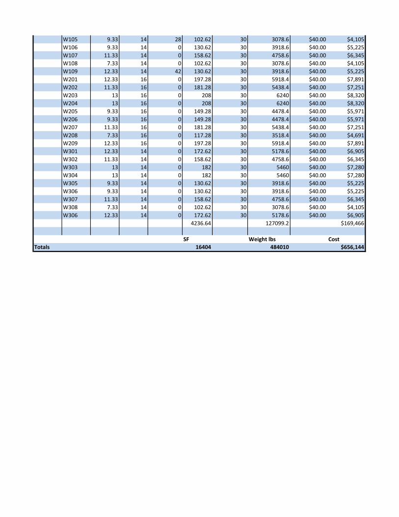
W105 9.33 14 28 102.62 30 3078.6 $40.00 $4,105W106 9.33 14 0 130.62 30 3918.6 $40.00 $5,225W107 11.33 14 0 158.62 30 4758.6 $40.00 $6,345W108 7.33 14 0 102.62 30 3078.6 $40.00 $4,105W109 12.33 14 42 130.62 30 3918.6 $40.00 $5,225W201 12.33 16 0 197.28 30 5918.4 $40.00 $7,891W202 11.33 16 0 181.28 30 5438.4 $40.00 $7,251W203 13 16 0 208 30 6240 $40.00 $8,320W204 13 16 0 208 30 6240 $40.00 $8,320W205 9.33 16 0 149.28 30 4478.4 $40.00 $5,971W206 9.33 16 0 149.28 30 4478.4 $40.00 $5,971W207 11.33 16 0 181.28 30 5438.4 $40.00 $7,251W208 7.33 16 0 117.28 30 3518.4 $40.00 $4,691W209 12.33 16 0 197.28 30 5918.4 $40.00 $7,891W301 12.33 14 0 172.62 30 5178.6 $40.00 $6,905W302 11.33 14 0 158.62 30 4758.6 $40.00 $6,345W303 13 14 0 182 30 5460 $40.00 $7,280W304 13 14 0 182 30 5460 $40.00 $7,280W305 9.33 14 0 130.62 30 3918.6 $40.00 $5,225W306 9.33 14 0 130.62 30 3918.6 $40.00 $5,225W307 11.33 14 0 158.62 30 4758.6 $40.00 $6,345W308 7.33 14 0 102.62 30 3078.6 $40.00 $4,105W306 12.33 14 0 172.62 30 5178.6 $40.00 $6,905
4236.64 127099.2 $169,466
SF Weight lbs CostTotals 16404 484010 $656,144

61
Appendix D: Panel Sizes Summary
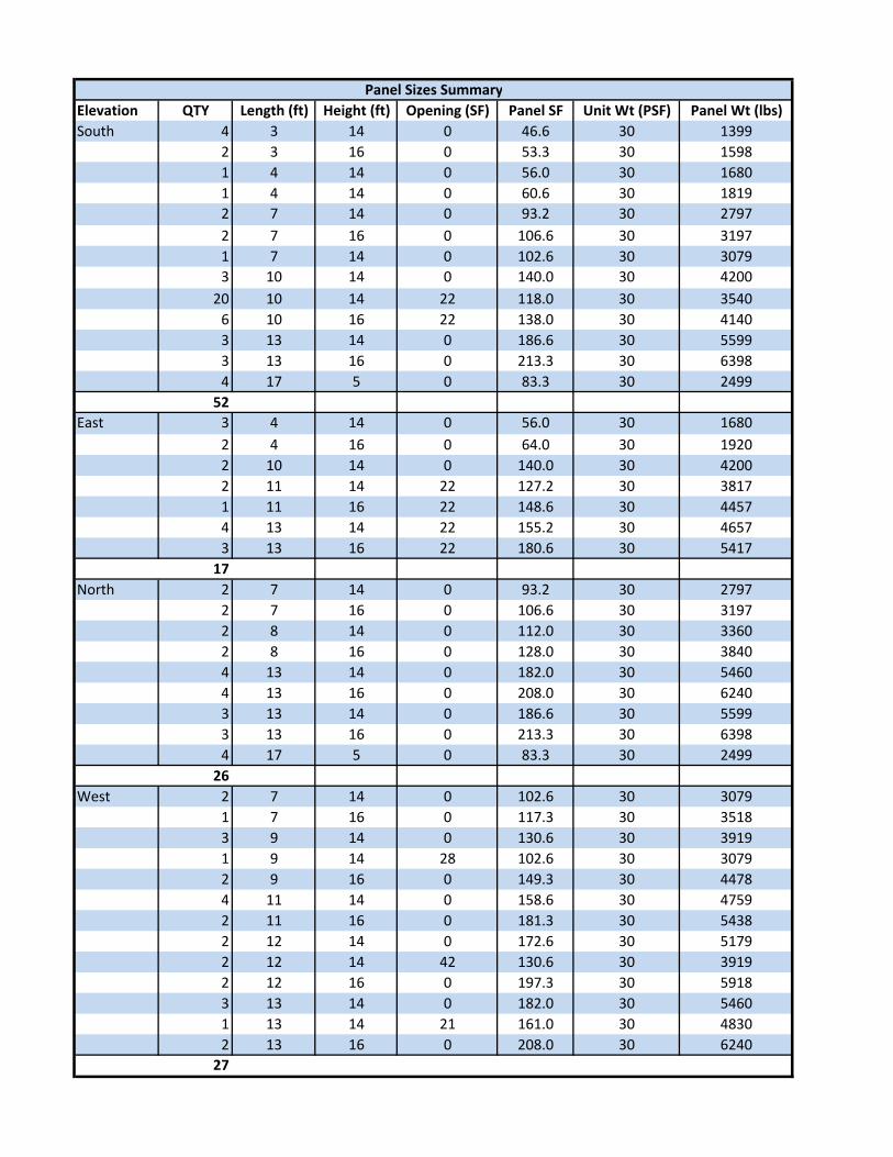
Elevation QTY Length (ft) Height (ft) Opening (SF) Panel SF Unit Wt (PSF) Panel Wt (lbs)South 4 3 14 0 46.6 30 1399
2 3 16 0 53.3 30 15981 4 14 0 56.0 30 16801 4 14 0 60.6 30 18192 7 14 0 93.2 30 27972 7 16 0 106.6 30 31971 7 14 0 102.6 30 30793 10 14 0 140.0 30 4200
20 10 14 22 118.0 30 35406 10 16 22 138.0 30 41403 13 14 0 186.6 30 55993 13 16 0 213.3 30 63984 17 5 0 83.3 30 2499
52East 3 4 14 0 56.0 30 1680
2 4 16 0 64.0 30 19202 10 14 0 140.0 30 42002 11 14 22 127.2 30 38171 11 16 22 148.6 30 44574 13 14 22 155.2 30 46573 13 16 22 180.6 30 5417
17North 2 7 14 0 93.2 30 2797
2 7 16 0 106.6 30 31972 8 14 0 112.0 30 33602 8 16 0 128.0 30 38404 13 14 0 182.0 30 54604 13 16 0 208.0 30 62403 13 14 0 186.6 30 55993 13 16 0 213.3 30 63984 17 5 0 83.3 30 2499
26West 2 7 14 0 102.6 30 3079
1 7 16 0 117.3 30 35183 9 14 0 130.6 30 39191 9 14 28 102.6 30 30792 9 16 0 149.3 30 44784 11 14 0 158.6 30 47592 11 16 0 181.3 30 54382 12 14 0 172.6 30 51792 12 14 42 130.6 30 39192 12 16 0 197.3 30 59183 13 14 0 182.0 30 54601 13 14 21 161.0 30 48302 13 16 0 208.0 30 6240
27
Panel Sizes Summary

63
Appendix E: Detailed Project Schedule – Alternative Exterior Façade
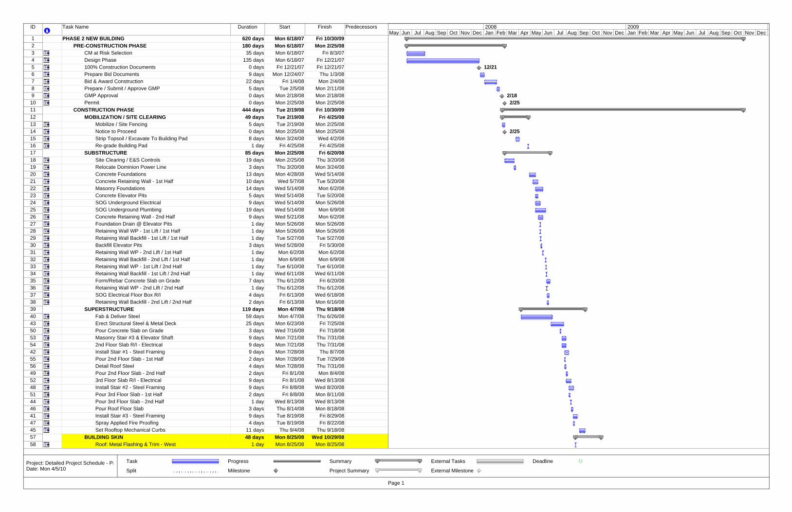
ID Task Name Duration Start Finish Predecessors
1 PHASE 2 NEW BUILDING 620 days Mon 6/18/07 Fri 10/30/092 PRE-CONSTRUCTION PHASE 180 days Mon 6/18/07 Mon 2/25/083 CM at Risk Selection 35 days Mon 6/18/07 Fri 8/3/074 Design Phase 135 days Mon 6/18/07 Fri 12/21/075 100% Construction Documents 0 days Fri 12/21/07 Fri 12/21/076 Prepare Bid Documents 9 days Mon 12/24/07 Thu 1/3/087 Bid & Award Construction 22 days Fri 1/4/08 Mon 2/4/088 Prepare / Submit / Approve GMP 5 days Tue 2/5/08 Mon 2/11/089 GMP Approval 0 days Mon 2/18/08 Mon 2/18/08
10 Permit 0 days Mon 2/25/08 Mon 2/25/0811 CONSTRUCTION PHASE 444 days Tue 2/19/08 Fri 10/30/0912 MOBILIZATION / SITE CLEARING 49 days Tue 2/19/08 Fri 4/25/0813 Mobilize / Site Fencing 5 days Tue 2/19/08 Mon 2/25/0814 Notice to Proceed 0 days Mon 2/25/08 Mon 2/25/0815 Strip Topsoil / Excavate To Building Pad 8 days Mon 3/24/08 Wed 4/2/0816 Re-grade Building Pad 1 day Fri 4/25/08 Fri 4/25/0817 SUBSTRUCTURE 85 days Mon 2/25/08 Fri 6/20/0818 Site Clearing / E&S Controls 19 days Mon 2/25/08 Thu 3/20/0819 Relocate Dominion Power Line 3 days Thu 3/20/08 Mon 3/24/0820 Concrete Foundations 13 days Mon 4/28/08 Wed 5/14/0821 Concrete Retaining Wall - 1st Half 10 days Wed 5/7/08 Tue 5/20/0822 Masonry Foundations 14 days Wed 5/14/08 Mon 6/2/0823 Concrete Elevator Pits 5 days Wed 5/14/08 Tue 5/20/0824 SOG Underground Electrical 9 days Wed 5/14/08 Mon 5/26/0825 SOG Underground Plumbing 19 days Wed 5/14/08 Mon 6/9/0826 Concrete Retaining Wall - 2nd Half 9 days Wed 5/21/08 Mon 6/2/0827 Foundation Drain @ Elevator Pits 1 day Mon 5/26/08 Mon 5/26/0828 Retaining Wall WP - 1st Lift / 1st Half 1 day Mon 5/26/08 Mon 5/26/0829 Retaining Wall Backfill - 1st Lift / 1st Half 1 day Tue 5/27/08 Tue 5/27/0830 Backfill Elevator Pits 3 days Wed 5/28/08 Fri 5/30/0831 Retaining Wall WP - 2nd Lift / 1st Half 1 day Mon 6/2/08 Mon 6/2/0832 Retaining Wall Backfill - 2nd Lift / 1st Half 1 day Mon 6/9/08 Mon 6/9/0833 Retaining Wall WP - 1st Lift / 2nd Half 1 day Tue 6/10/08 Tue 6/10/0834 Retaining Wall Backfill - 1st Lift / 2nd Half 1 day Wed 6/11/08 Wed 6/11/0835 Form/Rebar Concrete Slab on Grade 7 days Thu 6/12/08 Fri 6/20/0836 Retaining Wall WP - 2nd Lift / 2nd Half 1 day Thu 6/12/08 Thu 6/12/0837 SOG Electrical Floor Box R/I 4 days Fri 6/13/08 Wed 6/18/0838 Retaining Wall Backfill - 2nd Lift / 2nd Half 2 days Fri 6/13/08 Mon 6/16/0839 SUPERSTRUCTURE 119 days Mon 4/7/08 Thu 9/18/0840 Fab & Deliver Steel 59 days Mon 4/7/08 Thu 6/26/0843 Erect Structural Steel & Metal Deck 25 days Mon 6/23/08 Fri 7/25/0850 Pour Concrete Slab on Grade 3 days Wed 7/16/08 Fri 7/18/0853 Masonry Stair #3 & Elevator Shaft 9 days Mon 7/21/08 Thu 7/31/0854 2nd Floor Slab R/I - Electrical 9 days Mon 7/21/08 Thu 7/31/0842 Install Stair #1 - Steel Framing 9 days Mon 7/28/08 Thu 8/7/0855 Pour 2nd Floor Slab - 1st Half 2 days Mon 7/28/08 Tue 7/29/0856 Detail Roof Steel 4 days Mon 7/28/08 Thu 7/31/0849 Pour 2nd Floor Slab - 2nd Half 2 days Fri 8/1/08 Mon 8/4/0852 3rd Floor Slab R/I - Electrical 9 days Fri 8/1/08 Wed 8/13/0848 Install Stair #2 - Steel Framing 9 days Fri 8/8/08 Wed 8/20/0851 Pour 3rd Floor Slab - 1st Half 2 days Fri 8/8/08 Mon 8/11/0844 Pour 3rd Floor Slab - 2nd Half 1 day Wed 8/13/08 Wed 8/13/0846 Pour Roof Floor Slab 3 days Thu 8/14/08 Mon 8/18/0841 Install Stair #3 - Steel Framing 9 days Tue 8/19/08 Fri 8/29/0847 Spray Applied Fire Proofing 4 days Tue 8/19/08 Fri 8/22/0845 Set Rooftop Mechanical Curbs 11 days Thu 9/4/08 Thu 9/18/0857 BUILDING SKIN 48 days Mon 8/25/08 Wed 10/29/0858 Roof: Metal Flashing & Trim - West 1 day Mon 8/25/08 Mon 8/25/08
12/21
2/182/25
2/25
May Jun Jul Aug Sep Oct Nov Dec Jan Feb Mar Apr May Jun Jul Aug Sep Oct Nov Dec Jan Feb Mar Apr May Jun Jul Aug Sep Oct Nov Dec2008 2009
Task
Split
Progress
Milestone
Summary
Project Summary
External Tasks
External Milestone
Deadline
Page 1
Project: Detailed Project Schedule - PrDate: Mon 4/5/10
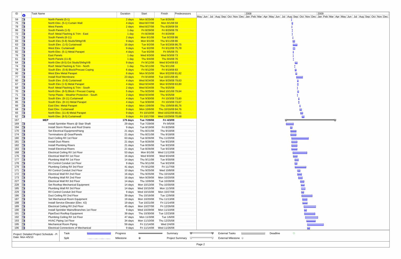
ID Task Name Duration Start Finish Predecessors
59 North Panels (5-1) 2 days Mon 8/25/08 Tue 8/26/0875 North Elev. (5-1) Curtain Wall 4 days Wed 8/27/08 Mon 9/1/08 5978 West Panels 2 days Wed 8/27/08 Thu 8/28/08 5986 South Panels (1-5) 1 day Fri 8/29/08 Fri 8/29/08 7872 Roof: Metal Flashing & Trim - East 1 day Fri 8/29/08 Fri 8/29/0873 South Panels (8-11) 2 days Mon 9/1/08 Tue 9/2/08 8683 South Elev (5-8) Studs/Sthtg/VB 9 days Mon 9/1/08 Thu 9/11/08 8663 South Elev. (1-5) Curtainwall 16 days Tue 9/2/08 Tue 9/23/08 86,7581 West Elev. Curtainwall 9 days Tue 9/2/08 Fri 9/12/08 75,7882 North Elev. (5-1) Metal Parapet 4 days Tue 9/2/08 Fri 9/5/08 7576 East Panels 1 day Wed 9/3/08 Wed 9/3/08 7361 North Panels (11-8) 1 day Thu 9/4/08 Thu 9/4/08 7664 North Elev (8-5) Ext Studs/Shthg/VB 9 days Fri 9/12/08 Wed 9/24/08 8374 Roof: Metal Flashing & Trim - North 1 day Thu 9/11/08 Thu 9/11/0879 South Elev. (5-8) Block/Precast Coping 6 days Fri 9/12/08 Fri 9/19/08 8380 West Elev Metal Parapet 6 days Mon 9/15/08 Mon 9/22/08 81,8277 Install Roof Membrane 23 days Fri 9/19/08 Tue 10/21/08 4560 South Elev. (5-8) Curtainwall 4 days Wed 9/24/08 Mon 9/29/08 79,6367 South Elev (1-5) Metal Parapet 4 days Wed 9/24/08 Mon 9/29/08 63,8069 Roof: Metal Flashing & Trim - South 2 days Wed 9/24/08 Thu 9/25/0870 North Elev. (8-5) Block / Precast Coping 5 days Thu 9/25/08 Wed 10/1/08 79,6471 Temp Plastic - Weather Protection - South 2 days Wed 9/24/08 Thu 9/25/0884 South Elev. (8-11) Curtainwall 4 days Tue 9/30/08 Fri 10/3/08 73,6085 South Elev. (8-11) Metal Parapet 4 days Tue 9/30/08 Fri 10/3/08 73,6766 East Elev. Metal Parapet 4 days Mon 10/6/08 Thu 10/9/08 85,7668 East Elev. Curtainwall 9 days Mon 10/6/08 Thu 10/16/08 84,7665 North Elev. (11-8) Metal Parapet 9 days Fri 10/10/08 Wed 10/22/08 66,6162 North Elev. (8-5) Curtainwall 9 days Fri 10/17/08 Wed 10/29/08 70,68
167 MEP 179 days Tue 7/29/08 Fri 4/3/09169 Install Sprinkler Risers @ Stair Shaft 29 days Tue 7/29/08 Fri 9/5/08194 Install Storm Risers and Roof Drains 9 days Tue 8/19/08 Fri 8/29/08170 Set Electrical Equipment/Hang 21 days Thu 8/21/08 Thu 9/18/08174 Terminations @ Gear/Panels 21 days Thu 8/21/08 Thu 9/18/08180 Duct Ceiling R/I 1st Floor 63 days Tue 8/26/08 Thu 11/20/08181 Install Duct Risers 21 days Tue 8/26/08 Tue 9/23/08182 Install Plumbing Risers 21 days Tue 8/26/08 Tue 9/23/08183 Install Electrical Risers 21 days Tue 8/26/08 Tue 9/23/08168 Electrical Ceiling R/I 1st Floor 53 days Mon 9/1/08 Wed 11/12/08176 Electrical Wall R/I 1st Floor 16 days Wed 9/3/08 Wed 9/24/08177 Plumbing Wall R/I 1st Floor 14 days Thu 9/11/08 Tue 9/30/08178 R/I Control Conduit 1st Floor 9 days Thu 9/11/08 Tue 9/23/08179 Plumbing Ceiling R/I 3rd Floor 41 days Fri 9/12/08 Fri 11/7/08171 R/I Control Conduit 2nd Floor 10 days Thu 9/25/08 Wed 10/8/08172 Electrical Wall R/I 2nd Floor 16 days Thu 9/25/08 Thu 10/16/08173 Plumbing Wall R/I 2nd Floor 16 days Mon 9/29/08 Mon 10/20/08227 Electrical Wall R/I 3rd Floor 14 days Thu 10/9/08 Tue 10/28/08228 Set Rooftop Mechanical Equipment 14 days Mon 10/13/08 Thu 10/30/08185 Plumbing Wall R/I 3rd Floor 14 days Wed 10/15/08 Mon 11/3/08229 R/I Control Conduit 3rd Floor 9 days Wed 10/15/08 Mon 10/27/08186 Duct Ceiling R/I 2nd Floor 39 days Thu 10/16/08 Tue 12/9/08187 Set Mechanical Room Equipment 19 days Mon 10/20/08 Thu 11/13/08188 Install Service Elevator (Elev. #2) 19 days Tue 10/21/08 Fri 11/14/08189 Electrical Ceiling R/I 2nd Floor 45 days Mon 10/27/08 Fri 12/26/08190 Install Sprinkler Mains/Branches 1st Floor 9 days Wed 10/29/08 Mon 11/10/08191 Pipe/Duct Rooftop Equipment 39 days Thu 10/30/08 Tue 12/23/08192 Plumbing Ceiling R/I 1st Floor 47 days Mon 11/3/08 Tue 1/6/09193 HVAC Piping 1st Floor 34 days Mon 11/10/08 Thu 12/25/08195 Mechanical Room Piping 59 days Fri 11/14/08 Wed 2/4/09196 Electrical Connections of Mechanical 9 days Fri 11/14/08 Wed 11/26/08
May Jun Jul Aug Sep Oct Nov Dec Jan Feb Mar Apr May Jun Jul Aug Sep Oct Nov Dec Jan Feb Mar Apr May Jun Jul Aug Sep Oct Nov Dec2008 2009
Task
Split
Progress
Milestone
Summary
Project Summary
External Tasks
External Milestone
Deadline
Page 2
Project: Detailed Project Schedule - PrDate: Mon 4/5/10
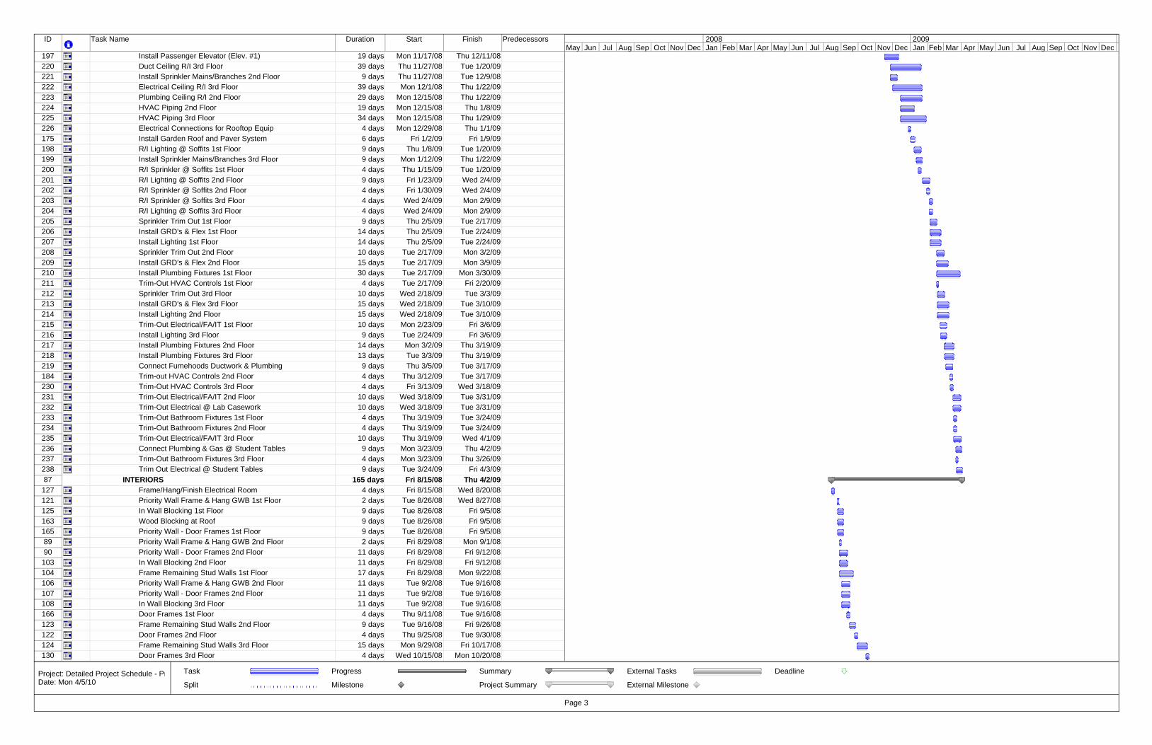
ID Task Name Duration Start Finish Predecessors
197 Install Passenger Elevator (Elev. #1) 19 days Mon 11/17/08 Thu 12/11/08220 Duct Ceiling R/I 3rd Floor 39 days Thu 11/27/08 Tue 1/20/09221 Install Sprinkler Mains/Branches 2nd Floor 9 days Thu 11/27/08 Tue 12/9/08222 Electrical Ceiling R/I 3rd Floor 39 days Mon 12/1/08 Thu 1/22/09223 Plumbing Ceiling R/I 2nd Floor 29 days Mon 12/15/08 Thu 1/22/09224 HVAC Piping 2nd Floor 19 days Mon 12/15/08 Thu 1/8/09225 HVAC Piping 3rd Floor 34 days Mon 12/15/08 Thu 1/29/09226 Electrical Connections for Rooftop Equip 4 days Mon 12/29/08 Thu 1/1/09175 Install Garden Roof and Paver System 6 days Fri 1/2/09 Fri 1/9/09198 R/I Lighting @ Soffits 1st Floor 9 days Thu 1/8/09 Tue 1/20/09199 Install Sprinkler Mains/Branches 3rd Floor 9 days Mon 1/12/09 Thu 1/22/09200 R/I Sprinkler @ Soffits 1st Floor 4 days Thu 1/15/09 Tue 1/20/09201 R/I Lighting @ Soffits 2nd Floor 9 days Fri 1/23/09 Wed 2/4/09202 R/I Sprinkler @ Soffits 2nd Floor 4 days Fri 1/30/09 Wed 2/4/09203 R/I Sprinkler @ Soffits 3rd Floor 4 days Wed 2/4/09 Mon 2/9/09204 R/I Lighting @ Soffits 3rd Floor 4 days Wed 2/4/09 Mon 2/9/09205 Sprinkler Trim Out 1st Floor 9 days Thu 2/5/09 Tue 2/17/09206 Install GRD's & Flex 1st Floor 14 days Thu 2/5/09 Tue 2/24/09207 Install Lighting 1st Floor 14 days Thu 2/5/09 Tue 2/24/09208 Sprinkler Trim Out 2nd Floor 10 days Tue 2/17/09 Mon 3/2/09209 Install GRD's & Flex 2nd Floor 15 days Tue 2/17/09 Mon 3/9/09210 Install Plumbing Fixtures 1st Floor 30 days Tue 2/17/09 Mon 3/30/09211 Trim-Out HVAC Controls 1st Floor 4 days Tue 2/17/09 Fri 2/20/09212 Sprinkler Trim Out 3rd Floor 10 days Wed 2/18/09 Tue 3/3/09213 Install GRD's & Flex 3rd Floor 15 days Wed 2/18/09 Tue 3/10/09214 Install Lighting 2nd Floor 15 days Wed 2/18/09 Tue 3/10/09215 Trim-Out Electrical/FA/IT 1st Floor 10 days Mon 2/23/09 Fri 3/6/09216 Install Lighting 3rd Floor 9 days Tue 2/24/09 Fri 3/6/09217 Install Plumbing Fixtures 2nd Floor 14 days Mon 3/2/09 Thu 3/19/09218 Install Plumbing Fixtures 3rd Floor 13 days Tue 3/3/09 Thu 3/19/09219 Connect Fumehoods Ductwork & Plumbing 9 days Thu 3/5/09 Tue 3/17/09184 Trim-out HVAC Controls 2nd Floor 4 days Thu 3/12/09 Tue 3/17/09230 Trim-Out HVAC Controls 3rd Floor 4 days Fri 3/13/09 Wed 3/18/09231 Trim-Out Electrical/FA/IT 2nd Floor 10 days Wed 3/18/09 Tue 3/31/09232 Trim-Out Electrical @ Lab Casework 10 days Wed 3/18/09 Tue 3/31/09233 Trim-Out Bathroom Fixtures 1st Floor 4 days Thu 3/19/09 Tue 3/24/09234 Trim-Out Bathroom Fixtures 2nd Floor 4 days Thu 3/19/09 Tue 3/24/09235 Trim-Out Electrical/FA/IT 3rd Floor 10 days Thu 3/19/09 Wed 4/1/09236 Connect Plumbing & Gas @ Student Tables 9 days Mon 3/23/09 Thu 4/2/09237 Trim-Out Bathroom Fixtures 3rd Floor 4 days Mon 3/23/09 Thu 3/26/09238 Trim Out Electrical @ Student Tables 9 days Tue 3/24/09 Fri 4/3/0987 INTERIORS 165 days Fri 8/15/08 Thu 4/2/09
127 Frame/Hang/Finish Electrical Room 4 days Fri 8/15/08 Wed 8/20/08121 Priority Wall Frame & Hang GWB 1st Floor 2 days Tue 8/26/08 Wed 8/27/08125 In Wall Blocking 1st Floor 9 days Tue 8/26/08 Fri 9/5/08163 Wood Blocking at Roof 9 days Tue 8/26/08 Fri 9/5/08165 Priority Wall - Door Frames 1st Floor 9 days Tue 8/26/08 Fri 9/5/0889 Priority Wall Frame & Hang GWB 2nd Floor 2 days Fri 8/29/08 Mon 9/1/0890 Priority Wall - Door Frames 2nd Floor 11 days Fri 8/29/08 Fri 9/12/08
103 In Wall Blocking 2nd Floor 11 days Fri 8/29/08 Fri 9/12/08104 Frame Remaining Stud Walls 1st Floor 17 days Fri 8/29/08 Mon 9/22/08106 Priority Wall Frame & Hang GWB 2nd Floor 11 days Tue 9/2/08 Tue 9/16/08107 Priority Wall - Door Frames 2nd Floor 11 days Tue 9/2/08 Tue 9/16/08108 In Wall Blocking 3rd Floor 11 days Tue 9/2/08 Tue 9/16/08166 Door Frames 1st Floor 4 days Thu 9/11/08 Tue 9/16/08123 Frame Remaining Stud Walls 2nd Floor 9 days Tue 9/16/08 Fri 9/26/08122 Door Frames 2nd Floor 4 days Thu 9/25/08 Tue 9/30/08124 Frame Remaining Stud Walls 3rd Floor 15 days Mon 9/29/08 Fri 10/17/08130 Door Frames 3rd Floor 4 days Wed 10/15/08 Mon 10/20/08
May Jun Jul Aug Sep Oct Nov Dec Jan Feb Mar Apr May Jun Jul Aug Sep Oct Nov Dec Jan Feb Mar Apr May Jun Jul Aug Sep Oct Nov Dec2008 2009
Task
Split
Progress
Milestone
Summary
Project Summary
External Tasks
External Milestone
Deadline
Page 3
Project: Detailed Project Schedule - PrDate: Mon 4/5/10
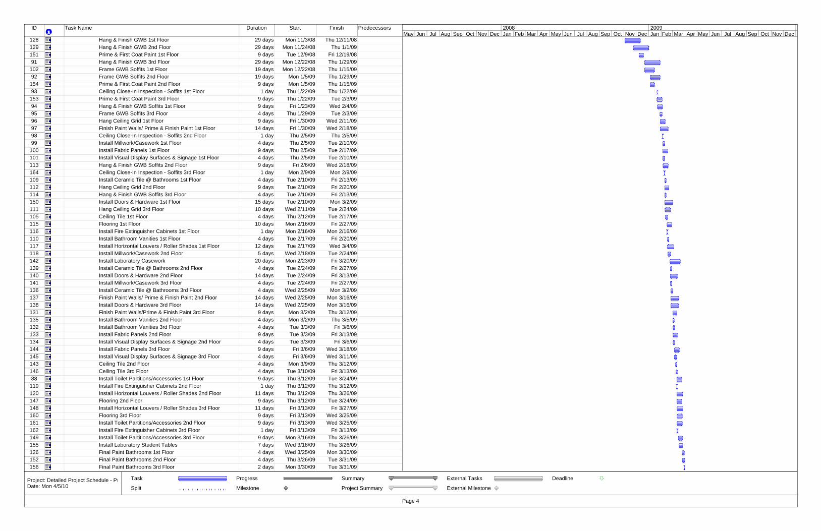
ID Task Name Duration Start Finish Predecessors
128 Hang & Finish GWB 1st Floor 29 days Mon 11/3/08 Thu 12/11/08129 Hang & Finish GWB 2nd Floor 29 days Mon 11/24/08 Thu 1/1/09151 Prime & First Coat Paint 1st Floor 9 days Tue 12/9/08 Fri 12/19/0891 Hang & Finish GWB 3rd Floor 29 days Mon 12/22/08 Thu 1/29/09
102 Frame GWB Soffits 1st Floor 19 days Mon 12/22/08 Thu 1/15/0992 Frame GWB Soffits 2nd Floor 19 days Mon 1/5/09 Thu 1/29/09
154 Prime & First Coat Paint 2nd Floor 9 days Mon 1/5/09 Thu 1/15/0993 Ceiling Close-In Inspection - Soffits 1st Floor 1 day Thu 1/22/09 Thu 1/22/09
153 Prime & First Coat Paint 3rd Floor 9 days Thu 1/22/09 Tue 2/3/0994 Hang & Finish GWB Soffits 1st Floor 9 days Fri 1/23/09 Wed 2/4/0995 Frame GWB Soffits 3rd Floor 4 days Thu 1/29/09 Tue 2/3/0996 Hang Ceiling Grid 1st Floor 9 days Fri 1/30/09 Wed 2/11/0997 Finish Paint Walls/ Prime & Finish Paint 1st Floor 14 days Fri 1/30/09 Wed 2/18/0998 Ceiling Close-In Inspection - Soffits 2nd Floor 1 day Thu 2/5/09 Thu 2/5/0999 Install Millwork/Casework 1st Floor 4 days Thu 2/5/09 Tue 2/10/09
100 Install Fabric Panels 1st Floor 9 days Thu 2/5/09 Tue 2/17/09101 Install Visual Display Surfaces & Signage 1st Floor 4 days Thu 2/5/09 Tue 2/10/09113 Hang & Finish GWB Soffits 2nd Floor 9 days Fri 2/6/09 Wed 2/18/09164 Ceiling Close-In Inspection - Soffits 3rd Floor 1 day Mon 2/9/09 Mon 2/9/09109 Install Ceramic Tile @ Bathrooms 1st Floor 4 days Tue 2/10/09 Fri 2/13/09112 Hang Ceiling Grid 2nd Floor 9 days Tue 2/10/09 Fri 2/20/09114 Hang & Finish GWB Soffits 3rd Floor 4 days Tue 2/10/09 Fri 2/13/09150 Install Doors & Hardware 1st Floor 15 days Tue 2/10/09 Mon 3/2/09111 Hang Ceiling Grid 3rd Floor 10 days Wed 2/11/09 Tue 2/24/09105 Ceiling Tile 1st Floor 4 days Thu 2/12/09 Tue 2/17/09115 Flooring 1st Floor 10 days Mon 2/16/09 Fri 2/27/09116 Install Fire Extinguisher Cabinets 1st Floor 1 day Mon 2/16/09 Mon 2/16/09110 Install Bathroom Vanities 1st Floor 4 days Tue 2/17/09 Fri 2/20/09117 Install Horizontal Louvers / Roller Shades 1st Floor 12 days Tue 2/17/09 Wed 3/4/09118 Install Millwork/Casework 2nd Floor 5 days Wed 2/18/09 Tue 2/24/09142 Install Laboratory Casework 20 days Mon 2/23/09 Fri 3/20/09139 Install Ceramic Tile @ Bathrooms 2nd Floor 4 days Tue 2/24/09 Fri 2/27/09140 Install Doors & Hardware 2nd Floor 14 days Tue 2/24/09 Fri 3/13/09141 Install Millwork/Casework 3rd Floor 4 days Tue 2/24/09 Fri 2/27/09136 Install Ceramic Tile @ Bathrooms 3rd Floor 4 days Wed 2/25/09 Mon 3/2/09137 Finish Paint Walls/ Prime & Finish Paint 2nd Floor 14 days Wed 2/25/09 Mon 3/16/09138 Install Doors & Hardware 3rd Floor 14 days Wed 2/25/09 Mon 3/16/09131 Finish Paint Walls/Prime & Finish Paint 3rd Floor 9 days Mon 3/2/09 Thu 3/12/09135 Install Bathroom Vanities 2nd Floor 4 days Mon 3/2/09 Thu 3/5/09132 Install Bathroom Vanities 3rd Floor 4 days Tue 3/3/09 Fri 3/6/09133 Install Fabric Panels 2nd Floor 9 days Tue 3/3/09 Fri 3/13/09134 Install Visual Display Surfaces & Signage 2nd Floor 4 days Tue 3/3/09 Fri 3/6/09144 Install Fabric Panels 3rd Floor 9 days Fri 3/6/09 Wed 3/18/09145 Install Visual Display Surfaces & Signage 3rd Floor 4 days Fri 3/6/09 Wed 3/11/09143 Ceiling Tile 2nd Floor 4 days Mon 3/9/09 Thu 3/12/09146 Ceiling Tile 3rd Floor 4 days Tue 3/10/09 Fri 3/13/0988 Install Toilet Partitions/Accessories 1st Floor 9 days Thu 3/12/09 Tue 3/24/09
119 Install Fire Extinguisher Cabinets 2nd Floor 1 day Thu 3/12/09 Thu 3/12/09120 Install Horizontal Louvers / Roller Shades 2nd Floor 11 days Thu 3/12/09 Thu 3/26/09147 Flooring 2nd Floor 9 days Thu 3/12/09 Tue 3/24/09148 Install Horizontal Louvers / Roller Shades 3rd Floor 11 days Fri 3/13/09 Fri 3/27/09160 Flooring 3rd Floor 9 days Fri 3/13/09 Wed 3/25/09161 Install Toilet Partitions/Accessories 2nd Floor 9 days Fri 3/13/09 Wed 3/25/09162 Install Fire Extinguisher Cabinets 3rd Floor 1 day Fri 3/13/09 Fri 3/13/09149 Install Toilet Partitions/Accessories 3rd Floor 9 days Mon 3/16/09 Thu 3/26/09155 Install Laboratory Student Tables 7 days Wed 3/18/09 Thu 3/26/09126 Final Paint Bathrooms 1st Floor 4 days Wed 3/25/09 Mon 3/30/09152 Final Paint Bathrooms 2nd Floor 4 days Thu 3/26/09 Tue 3/31/09156 Final Paint Bathrooms 3rd Floor 2 days Mon 3/30/09 Tue 3/31/09
May Jun Jul Aug Sep Oct Nov Dec Jan Feb Mar Apr May Jun Jul Aug Sep Oct Nov Dec Jan Feb Mar Apr May Jun Jul Aug Sep Oct Nov Dec2008 2009
Task
Split
Progress
Milestone
Summary
Project Summary
External Tasks
External Milestone
Deadline
Page 4
Project: Detailed Project Schedule - PrDate: Mon 4/5/10
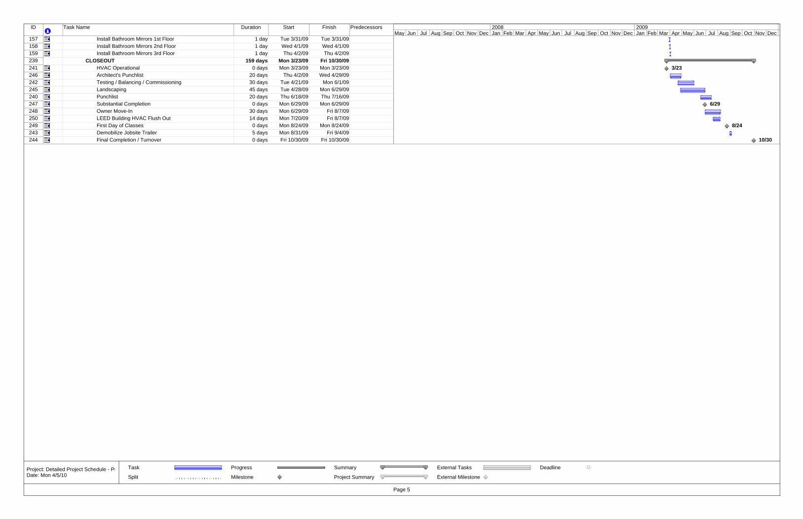
ID Task Name Duration Start Finish Predecessors
157 Install Bathroom Mirrors 1st Floor 1 day Tue 3/31/09 Tue 3/31/09158 Install Bathroom Mirrors 2nd Floor 1 day Wed 4/1/09 Wed 4/1/09159 Install Bathroom Mirrors 3rd Floor 1 day Thu 4/2/09 Thu 4/2/09239 CLOSEOUT 159 days Mon 3/23/09 Fri 10/30/09241 HVAC Operational 0 days Mon 3/23/09 Mon 3/23/09246 Architect's Punchlist 20 days Thu 4/2/09 Wed 4/29/09242 Testing / Balancing / Commissioning 30 days Tue 4/21/09 Mon 6/1/09245 Landscaping 45 days Tue 4/28/09 Mon 6/29/09240 Punchlist 20 days Thu 6/18/09 Thu 7/16/09247 Substantial Completion 0 days Mon 6/29/09 Mon 6/29/09248 Owner Move-In 30 days Mon 6/29/09 Fri 8/7/09250 LEED Building HVAC Flush Out 14 days Mon 7/20/09 Fri 8/7/09249 First Day of Classes 0 days Mon 8/24/09 Mon 8/24/09243 Demobilize Jobsite Trailer 5 days Mon 8/31/09 Fri 9/4/09244 Final Completion / Turnover 0 days Fri 10/30/09 Fri 10/30/09
3/23
6/29
8/24
10/30
May Jun Jul Aug Sep Oct Nov Dec Jan Feb Mar Apr May Jun Jul Aug Sep Oct Nov Dec Jan Feb Mar Apr May Jun Jul Aug Sep Oct Nov Dec2008 2009
Task
Split
Progress
Milestone
Summary
Project Summary
External Tasks
External Milestone
Deadline
Page 5
Project: Detailed Project Schedule - PrDate: Mon 4/5/10

69
Appendix F: Detailed Exterior Façade Systems Cost Comparison
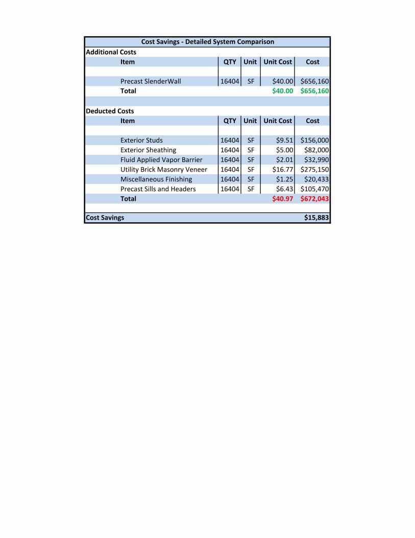
Additional CostsItem QTY Unit Unit Cost Cost
Precast SlenderWall 16404 SF $40.00 $656,160Total $40.00 $656,160
Deducted CostsItem QTY Unit Unit Cost Cost
Exterior Studs 16404 SF $9.51 $156,000Exterior Sheathing 16404 SF $5.00 $82,000Fluid Applied Vapor Barrier 16404 SF $2.01 $32,990Utility Brick Masonry Veneer 16404 SF $16.77 $275,150Miscellaneous Finishing 16404 SF $1.25 $20,433Precast Sills and Headers 16404 SF $6.43 $105,470Total $40.97 $672,043
Cost Savings $15,883
Cost Savings ‐ Detailed System Comparison

71
Appendix G: TPO “Cool” Roof Thermal Properties
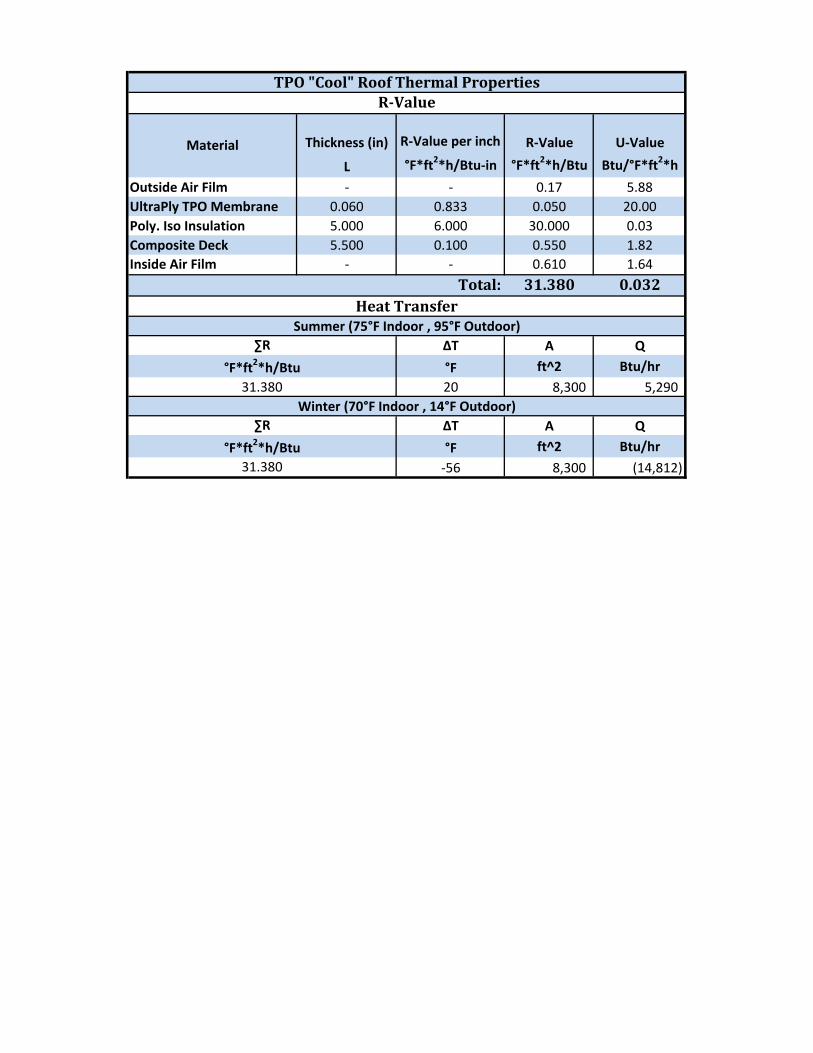
Thickness (in) R‐Value per inch R‐Value U‐Value
L °F*ft2*h/Btu‐in °F*ft2*h/Btu Btu/°F*ft2*h
Outside Air Film ‐ ‐ 0.17 5.88UltraPly TPO Membrane 0.060 0.833 0.050 20.00Poly. Iso Insulation 5.000 6.000 30.000 0.03Composite Deck 5.500 0.100 0.550 1.82Inside Air Film ‐ ‐ 0.610 1.64
31.380 0.032
ΔT A Q
°F ft^2 Btu/hr20 8,300 5,290
ΔT A Q
°F ft^2 Btu/hr
‐56 8,300 (14,812) 31.380°F*ft2*h/Btu
∑R
31.380°F*ft2*h/Btu
Winter (70°F Indoor , 14°F Outdoor)
∑R
TPO "Cool" Roof Thermal Properties
Total:
RValue
Heat TransferSummer (75°F Indoor , 95°F Outdoor)
Material

73
Appendix H: Detailed Roofing Systems Cost Comparison
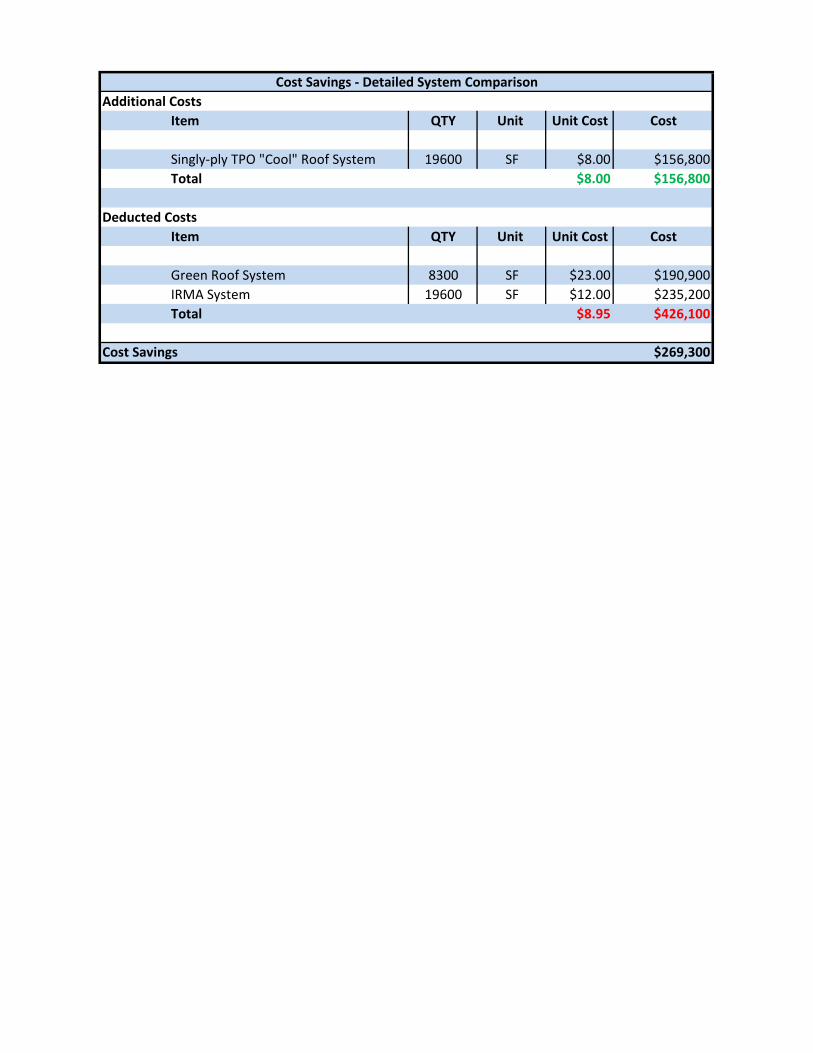
Additional CostsItem QTY Unit Unit Cost Cost
Singly‐ply TPO "Cool" Roof System 19600 SF $8.00 $156,800Total $8.00 $156,800
Deducted CostsItem QTY Unit Unit Cost Cost
Green Roof System 8300 SF $23.00 $190,900IRMA System 19600 SF $12.00 $235,200Total $8.95 $426,100
Cost Savings $269,300
Cost Savings ‐ Detailed System Comparison