Embed Size (px)
Citation preview
“pH CONTROL IN A BIOREACTOR”
USING DAQ 6009
Project report submitted in fulfillment of the requirements
For the award of the degree of
BACHELOR OF TECHNOLOGY
IN
ELECTRICAL AND ELECTRONICS ENGINEERING
BY
S.KAMAL VISWANATH (07241A0206)
M.CHIRANJEEVI (07241A0231)
M.RAMESH (07241A0245)
K.SHRAVAN (07241A0247)
Under the guidance of
Sri.E.VENKATESHWARULU
Department of EEE
Department of Electrical and Electronics Engineering
Gokaraju Rangaraju Institute of Engineering & Technology
(Affiliated to Jawaharlal Nehru Technological University)
Hyderabad
2007 - 2011

GOKARAJU RANGARAJU INSTITUTE OF ENGINEERING AND
TECHNOLOGY
Hyderabad, Andhra Pradesh.
DEPARTMENT OF ELECTRICAL & ELECTRONICS ENGINEERING
This is to certify that the project report entitled “pH CONTROL IN A
BIOREACTOR” that is being submitted by KAMAL VISWANATH, CHIRANJEEVI,
RAMESH, SHRAVAN, in partial fulfillment for the award of the Degree of Bachelor of
Technology in Electrical and Electronics Engineering to the Jawaharlal Nehru
Technological University is a record of bonafide work carried out by them under my
guidance and supervision. The results embodied in this project report have not been
submitted to any other University or Institute for the award of any Graduation degree.
Head of Department Project Coordinator Internal Guide
Prof.P.M.SHARMA Prof. S.N.Saxena Sri. E.Venkateshwarulu
Professor & HOD Professor Assistant Professor
EEE, GRIET EEE, GRIET EEE, GRIET

ACKNOWLEDGMENT
This is to place on record my appreciation and deep gratitude to the persons without
whose support this project would never seen the light of day.
I wish to express my propound sense of gratitude to Sri. P. S. Raju, Director,
G.R.I.E.T for his guidance, encouragement, and for all facilities to complete this project.
I have immense pleasure in expressing my thanks and deep sense of gratitude to my
guide Sri.E.Venkateshwarulu, Assistant Professor, Department of Electrical and
Electronics Engineering, G.R.I.E.T for his guidance throughout this project.
I also express my sincere thanks to Sri.P.M.Sarma, Head of the Department,
G.R.I.E.T and for extending their help.
I express my gratitude to Mr. S.N. Saxena, Professor, Department of Electrical and
Electronics Engineering, Coordinator, Project Review Committee, G.R.I.E.T for his
valuable recommendations and for accepting this project report.
Finally I express my sincere gratitude to Sri. M. Chakravarthy , Associate Professor,
Department of Electrical and Electronics Engineering, G.R.I.E.T and all the members of
faculty and my friends who contributed their valuable advice and helped to complete the
project successfully.
S. Kamal Viswanath (07241A206)
M. Chiranjeevi (07241A0231)
M. Ramesh (07241A0245)
K.Sharavan (07241A0247)
ABSTARCT
The aim of developing this project is to
automate the control of the pH of solution in a bioreactor. A bioreactor is a
vessel in which is carried out a chemical process which involves organisms or
biochemically active substances derived from such organisms. Under optimum
conditions the microorganisms or cells will reproduce at an astounding rate. So
the conditions like temperature, pH value, oxygen rate are to be maintained. The
main idea of the project is to amplify the voltage that is generated by the pH
sensor and send this voltage to a controlling component. This component is to
be selected such that two limits an upper and a lower limit can be set to it, by
which any change in the amplifier voltage beyond the limits an output signal is
to be generated by the control circuit. This signal will control the pH by adding
pH solutions to it. This project is practical and highly feasible in economic point
of view, and has an advantage of controlling the pH value in a wide range. This
project is an automated, reliable and adaptable way of controlling the pH value
in a bioreactor.
CONTENTS

Abstract II List of figures V List of Tables VI
Chapter 1. Introduction 1
1.1 Bioreactor 1 1.2 pH 3 1.3 pH sensor 4 1.4 Operational Amplifiers 7 1.5 DAQ 10
Chapter 2. Block Diagram 13
Chapter 3. Circuit Diagram 14
Chapter 4. System Simulation Results 15 Chapter 5. Hardware Description 17 5.1 Hardware Circuit 18
Chapter 6. Software Description 19
6.1 Multisim 19 6.1.1 Use of Multisim in this project 19
6.2 LabVIEW 21 6.2.1 Use of LabVIEW in this project 22 6.2.2 Interfacing with DAQ 22
Chapter 7. Outputs Observed 24
Chapter 8. Conclusion and Scope for future work 29
8.1 Conclusion 29

8.2 Scope for future work 29
References 30 Appendix A 31 Appendix B 32 Appendix C 37
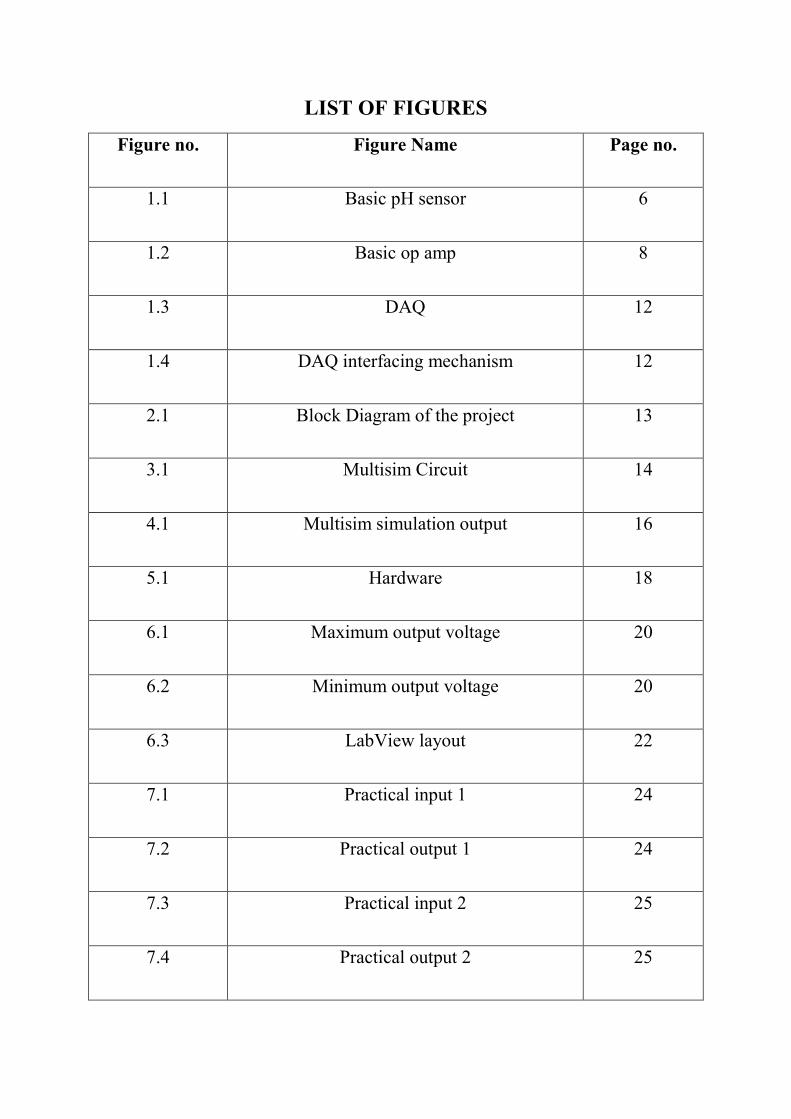
LIST OF FIGURES
Figure no. Figure Name Page no.
1.1 Basic pH sensor 6
1.2 Basic op amp 8
1.3 DAQ 12
1.4 DAQ interfacing mechanism 12
2.1 Block Diagram of the project 13
3.1 Multisim Circuit 14
4.1 Multisim simulation output 16
5.1 Hardware 18
6.1 Maximum output voltage 20
6.2 Minimum output voltage 20
6.3 LabView layout 22
7.1 Practical input 1 24
7.2 Practical output 1 24
7.3 Practical input 2 25
7.4 Practical output 2 25

7.5 Below the limit output 26
7.6 Within the limit output 26
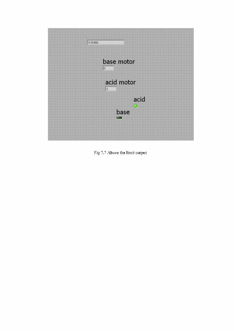
7.7 Above the limit output 27
List of tables
Table no. Table name Page no.
4.1 System simulation results table 15
7.1 Practical results table 28

CHAPTER-1
INTRODUCTION
pH control is the one of the most important aspect that is to be maintained in a bioreactor. This is achieved by a set of equipments and circuits. The main blocks of this project are:
• pH sensing device • Amplification circuit • Controlling device
By combining all these blocks the output is achieved which is to control the pH value in a bioreactor. The working of a project is better understood if explained in parts.
1.1 BIOREACTOR:
A bioreactor is a vessel in which is carried out a chemical process which involves organisms or biochemically active substances derived from such organisms. Bioreactors are commonly cylindrical, ranging in size from some liter to cube meters, and are often made of stainless steel. Bioreactor design is quite a complex engineering task. Under optimum conditions the microorganisms or cells will reproduce at an astounding rate. The vessel's environmental conditions like gas (i.e., air, oxygen, nitrogen, carbon dioxide) flow rates, temperature, pH and dissolved oxygen levels, and agitation speed need to be closely monitored and controlled. One bioreactor manufacturer, Bradley-James Corporation, uses vessels, sensors, controllers, and a control system, digitally networked together for their bioreactor system.
Cell culture bioreactors are categorized into two types: 1. those that are used for cultivation of anchorage dependent cells (e.g. primary cultures derived from normal tissues and diploid cell lines. 2. Those that are used for the cultivation of suspended mammalian cells (e.g. cell lines derived from cancerous tissues and tumors, transformed diploid cell lines, hybridomas). In some cases the bioreactor may be modified to grow both anchorage dependent and suspended cells. Ideally any cell culture bioreactor must maintain a sterile culture of cells in medium conditions which maximize cell growth and productivity.
Fouling can harm the overall sterility and efficiency of the bioreactor, especially the heat exchangers. To avoid it the bioreactor must be easily cleanable and must be as smooth as possible (therefore the round shape). The pH value of the substance is to be maintained constant.
Heat exchange is needed to maintain the bioprocess at a constant temperature. Biological fermentation is a major source of heat; therefore in most cases bioreactors need water

refrigeration. They can be refrigerated with an external jacket or, for very large vessels, with internal coils. Optimal oxygen transfer is perhaps the most difficult task to accomplish. Oxygen is poorly soluble in water -and even less in fermentation broths- and is relatively scarce in air (20.8%). Oxygen transfer is usually helped by agitation that is also needed to mix nutrients and to keep the fermentation homogeneous. There is however limits to the speed of agitation, due both to high power consumption (that's proportional to the cube of the speed) and the damage to organisms due to excessive tip speed. Bioreactor treatment may be performed using microorganisms growing in suspension in the fluid or attached on a solid growth support medium. In suspended growth systems, such as fluidized beds or sequencing batch reactors, contaminated groundwater is circulated in an aeration basin where a microbial population aerobically degrades organic matter and produces carbon dioxide, water, and biomass. The biomass is settled out in a clarifier, then either recycled back to the aeration basin or disposed of as sludge. In attached growth systems, such as up flow fixed film bioreactors, rotating biological contactors (RBCs), and trickling filters, microorganisms are grown as a biofilm on a solid growth support matrix and water contaminants are degraded as they diffuse into the biofilm. Support media include solids that have a large surface area for bacterial attachment.
Moisture content is the single most important factor that promotes the accelerated decomposition. The bioreactor technology relies on maintaining optimal moisture content near field capacity (approximately 35 to 65%) and adds liquids when it is necessary to maintain that percentage. The moisture content, combined with the biological action of naturally occurring microbes decomposes the waste. The microbes can be either aerobic or anaerobic. A side effect of the bioreactor is that it produces landfill gas (LFG) such as methane in an anaerobic unit at an earlier stage in the landfill’s life and at an overall much higher rate of generation than traditional landfills.
Bioreactors have a wide range of applications in various fields like
• Medicine: The immobilized enzyme reactors are one of the most recent achievements in the field of medicine.
• Environment : Water purification plants, sewage plant bioreactors, land filling bioreactors has bought a major change in the recycle of the waste in the environment Other than these advantages bioreactors find a wide range of applications in industries, research and food processing plants.

1.2 pH:
pH is a measure of the acidity or basicity of an aqueous solution. Pure water is said to be neutral, with a pH close to 7.0 at 25 °C (77 °F). Solutions with a pH less than 7 are said to be acidic and solutions with a pH greater than 7 are basic or alkaline. pH measurements are important in medicine, biology, food science, environmental science, oceanography, civil engineering and many other applications. In a solution pH approximates but is not equal to p[H], the negative logarithm (base 10) of the molar concentration of dissolved hydronium ions (H3O+); a low pH indicates a high concentration of hydronium ions, while a high pH indicates a low concentration. This negative of the logarithm matches the number of places behind the decimal point, so, for example, 0.1 molar hydrochloric acid should be near pH 1 and 0.0001 molar HCl should be near pH 4 (the base 10 logarithms of 0.1 and 0.0001 being −1, and −4, respectively). Pure (de-ionized) water is neutral, and can be considered either a very weak acid or a very weak base (center of the 0 to 14 pH scale), giving it a pH of 7 (at 25 °C (77 °F)), or 0.0000001 M H+. For an aqueous solution to have a higher pH, a base must be dissolved in it, which binds away many of these rare hydrogen ions. Hydrogen ions in water can be written simply as H+ or as hydronium (H3O+) or higher species (e.g., H9O4
+) to account for solvation, but all describe the same entity. Most of the Earth's freshwater surface bodies are slightly acidic due to the abundance and absorption of carbon dioxide; in fact, for millennia in the past, most fresh water bodies have long existed at a slightly acidic pH level.
However, pH is not precisely p[H], but takes into account an activity factor. This represents the tendency of hydrogen ions to interact with other components of the solution, which affects among other things the electrical potential read using a pH meter. As a result, pH can be affected by the ionic strength of a solution – for example, the pH of a 0.05 M potassium hydrogen phthalate solution can vary by as much as 0.5 pH units as a function of added potassium chloride, even though the added salt is neither acidic nor basic.
Hydrogen ion activity coefficients cannot be measured directly by any thermodynamically sound method, so they are based on theoretical calculations. Therefore, the pH scale is defined in practice as traceable to a set of standard solutions whose pH is established by international agreement.
It is unknown what the exact definition of 'p' in pH is. A common definition often used in schools is "percentage". However some references suggest the p stands for “Power”, others refer to the German word “Potenz” (meaning power in German), still others refer to “potential”. Jens Norby published a paper in 2000 arguing that p is a constant and stands for “negative logarithm”; H then stands for Hydrogen. According to the Carlsberg Foundation pH stands for "power of hydrogen". Other suggestions that have surfaced over the years are that the p stands for puissance (also meaning power, but, then, the Carlsberg Laboratory was French-speaking) or that pH stands for the Latin terms pondus Hydrogenii or potentia hydrogenii. It is also suggested that Sorensen used the letters p and q (commonly paired letters in mathematics) simply to label the test solution (p) and the reference solution (q).
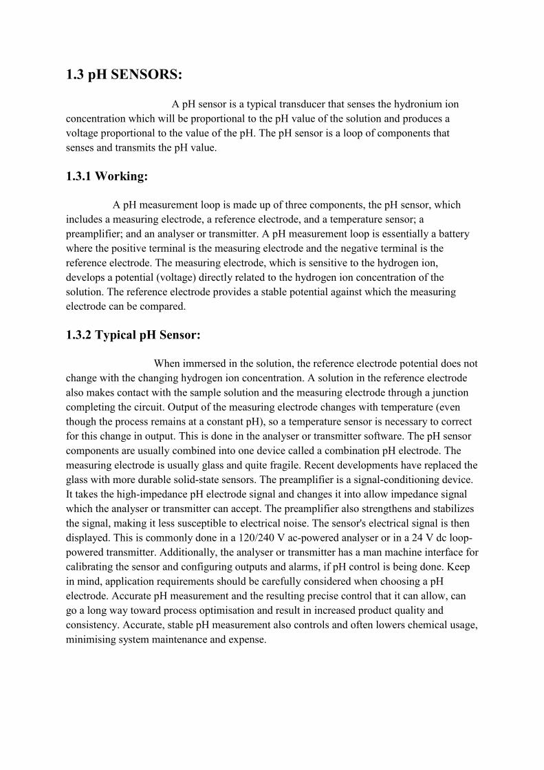
1.3 pH SENSORS:
A pH sensor is a typical transducer that senses the hydronium ion concentration which will be proportional to the pH value of the solution and produces a voltage proportional to the value of the pH. The pH sensor is a loop of components that senses and transmits the pH value.
1.3.1 Working:
A pH measurement loop is made up of three components, the pH sensor, which includes a measuring electrode, a reference electrode, and a temperature sensor; a preamplifier; and an analyser or transmitter. A pH measurement loop is essentially a battery where the positive terminal is the measuring electrode and the negative terminal is the reference electrode. The measuring electrode, which is sensitive to the hydrogen ion, develops a potential (voltage) directly related to the hydrogen ion concentration of the solution. The reference electrode provides a stable potential against which the measuring electrode can be compared.
1.3.2 Typical pH Sensor:
When immersed in the solution, the reference electrode potential does not change with the changing hydrogen ion concentration. A solution in the reference electrode also makes contact with the sample solution and the measuring electrode through a junction completing the circuit. Output of the measuring electrode changes with temperature (even though the process remains at a constant pH), so a temperature sensor is necessary to correct for this change in output. This is done in the analyser or transmitter software. The pH sensor components are usually combined into one device called a combination pH electrode. The measuring electrode is usually glass and quite fragile. Recent developments have replaced the glass with more durable solid-state sensors. The preamplifier is a signal-conditioning device. It takes the high-impedance pH electrode signal and changes it into allow impedance signal which the analyser or transmitter can accept. The preamplifier also strengthens and stabilizes the signal, making it less susceptible to electrical noise. The sensor's electrical signal is then displayed. This is commonly done in a 120/240 V ac-powered analyser or in a 24 V dc loop-powered transmitter. Additionally, the analyser or transmitter has a man machine interface for calibrating the sensor and configuring outputs and alarms, if pH control is being done. Keep in mind, application requirements should be carefully considered when choosing a pH electrode. Accurate pH measurement and the resulting precise control that it can allow, can go a long way toward process optimisation and result in increased product quality and consistency. Accurate, stable pH measurement also controls and often lowers chemical usage, minimising system maintenance and expense.

1.3.3 Keeping the System Up and Running: A system's pH electrodes require periodic maintenance to clean and calibrate them. The length of time between cleaning and calibration depends on process conditions and the user's accuracy and stability expectations. Overtime, electrical properties of the measuring and reference electrode change. Calibration in known-value pH solutions called buffers will correct for some of these changes. Cleaning of the measuring sensor and reference junction will also help. However, just as batteries have a limited life, a pH electrode's lifetime is also finite. Even in the "friendliest" environments, pH electrodes have to be replaced eventually.
1.3.4 Calibration and Use:
For very precise work the pH meter should be calibrated before each measurement. For normal use calibration should be performed at the beginning of each day. The reason for this is that the glass electrode does not give a reproducible e.m.f. over longer periods of time. Calibration should be performed with at least two standard buffer solutions that span the range of pH values to be measured. For general purposes buffers at pH 4 and pH 10 are acceptable. The pH meter has one control (calibrate) to set the meter reading equal to the value of the first standard buffer and a second control (slope) which is used to adjust the meter reading to the value of the second buffer. A third control allows the temperature to be set. Standard buffer sachets, which can be obtained from a variety of suppliers, usually state how the buffer value changes with temperature. The calibration process correlates the voltage produced by the probe (approximately 0.06 volts per pH unit) with the pH scale. After each single measurement, the probe is rinsed with distilled water or deionized water to remove any traces of the solution being measured, blotted with a clean tissue to absorb any remaining water which could dilute the sample and thus alter the reading, and then quickly immersed in another solution.

1.3.5 Types of pH Meters
A simple pH meter pH meters range from simple and inexpensive pen-like devices to complex and expensive laboratory instruments with computer interfaces and several inputs for indicatoreraturevariation in pH caused by temperature. Specialty meters and probes are available for use in special applications, harsh environments, etc.around 1936 by Radiometer in Denmark and byStates. While Beckman was an assistant professor of chemistry at theTechnology, he was asked to devise a quick and accurate method for measuring the acidity of lemon juice for the California Fruit Growers Exchangehelped him to launch the Beckman Instruments company (nowthe Beckman pH meter was designated anrecognition of its significance as the first commercially successful electronic pH meter.
Types of pH Meters:
A simple pH meter pH meters range from simple and inexpensive like devices to complex and expensive laboratory instruments with computer interfaces
and several inputs for indicatorerature measurements be entered to adjust for the slight variation in pH caused by temperature. Specialty meters and probes are available for use in special applications, harsh environments, etc. The first commercial pH meters were built
in Denmark and by Arnold Orville Beckman in the United States. While Beckman was an assistant professor of chemistry at the California Institute of
, he was asked to devise a quick and accurate method for measuring the acidity California Fruit Growers Exchange (Sunkist). Beckman's invention
Beckman Instruments company (now Beckman Coulterthe Beckman pH meter was designated an ACS National Historical Chemical Landmarkrecognition of its significance as the first commercially successful electronic pH meter.
A simple pH meter pH meters range from simple and inexpensive like devices to complex and expensive laboratory instruments with computer interfaces
measurements be entered to adjust for the slight variation in pH caused by temperature. Specialty meters and probes are available for use in
The first commercial pH meters were built in the United
California Institute of , he was asked to devise a quick and accurate method for measuring the acidity
). Beckman's invention Beckman Coulter). In 2004
ACS National Historical Chemical Landmark in recognition of its significance as the first commercially successful electronic pH meter.[2]
1.4 OPERATIONAL AMPLIFIERS (OPAMPS):
coupled high-gain electronic voltageended output. An op-amp produces an output voltage that is typically hundreds of thousands times larger than the voltage differenceare important building blocks for a wide range of electronic circuits. They had their origins in analog computers where they were used in many linear, nondependent circuits. Their popularity in circuit design largely stems from the fact the characteristics of the final elements (such as theirlittle dependence on temperature changesOp-amps are among the most widely used electronic devices today, being used in a vast array of consumer, industrial, and scientific devices. Many standard IC opcents in moderate production volume; however some integrated or hybrid operational amplifiers with special performance specifications may cost over $100 US in small quantities. Op-amps may be packaged as components, or used as elements of more complex integrated circuits. The op-amp is one type ofdifferential amplifier include thetwo outputs), the instrumentation amplifieramplifier (similar to the instrumentation amplifier, but with tolerance to commonvoltages that would destroy an ordinary opbuilt from one or more op-amps and a resistive feedback network).
1.4.1Operation:
The amplifier's differential inputs consist of aideally the op-amp amplifies only the difference in voltage between the the differential input voltage. The output voltage of the op
where is the voltage at the nonterminal and AOL is the open-loopabsence of a feedback loop from the output to the inputvery large—10,000 or more for integrated circuit op
difference between and is called saturation of the amplifier. The magnitude ofmanufacturing process, and so it is impractical to use an operational amplifier as a standalone differential amplifier. If predictable operation is desired,applying a portion of the output voltage to the inverting input. The greatly reduces the gain of the amplifier. If negative feedback gain and other parameters become determined more by the feedback network than by the opamp itself. If the feedback network is made of components with relatively constant, stable values, the unpredictability and inconstancy o
IONAL AMPLIFIERS (OPAMPS):
An operational amplifier ("op-amp") is aelectronic voltage amplifier with a differential input and, usually, a single
amp produces an output voltage that is typically hundreds of thousands difference between its input terminals. Operational amplifiers
ilding blocks for a wide range of electronic circuits. They had their origins where they were used in many linear, non-linear and frequency
uits. Their popularity in circuit design largely stems from the fact the characteristics of the final elements (such as their gain) are set by external components with little dependence on temperature changes and manufacturing variations in the op
amps are among the most widely used electronic devices today, being used in a vast array of consumer, industrial, and scientific devices. Many standard IC op-amps cost only a few
uction volume; however some integrated or hybrid operational amplifiers with special performance specifications may cost over $100 US in small
amps may be packaged as components, or used as elements of more complex amp is one type of differential amplifier. Other types of
differential amplifier include the fully differential amplifier (similar to the opinstrumentation amplifier (usually built from three op-amps), the
(similar to the instrumentation amplifier, but with tolerance to commonvoltages that would destroy an ordinary op-amp), and negative feedback amplifier
amps and a resistive feedback network).
The amplifier's differential inputs consist of a input and aamp amplifies only the difference in voltage between the two, which is called
. The output voltage of the op-amp is given by the equation,
is the voltage at the non-inverting terminal, is the voltage at the inverting loop gain of the amplifier. (The term "open-loop" refers to the
op from the output to the input). The magnitude offor integrated circuit op-amps—and therefore even a quite small
drives the amplifier output nearly to the supply voltage. This of the amplifier. The magnitude of AOL is not well controlled by the
manufacturing process, and so it is impractical to use an operational amplifier as a stand. If predictable operation is desired, negative feedback
applying a portion of the output voltage to the inverting input. The closed loopgreatly reduces the gain of the amplifier. If negative feedback is used, the circuit's overall gain and other parameters become determined more by the feedback network than by the opamp itself. If the feedback network is made of components with relatively constant, stable values, the unpredictability and inconstancy of the op-amp's parameters do not seriously
amp") is a DC-with a differential input and, usually, a single-
amp produces an output voltage that is typically hundreds of thousands Operational amplifiers
ilding blocks for a wide range of electronic circuits. They had their origins linear and frequency-
uits. Their popularity in circuit design largely stems from the fact the ) are set by external components with
and manufacturing variations in the op-amp itself. amps are among the most widely used electronic devices today, being used in a vast array
amps cost only a few uction volume; however some integrated or hybrid operational
amplifiers with special performance specifications may cost over $100 US in small amps may be packaged as components, or used as elements of more complex
. Other types of (similar to the op-amp, but with
amps), the isolation (similar to the instrumentation amplifier, but with tolerance to common-mode
negative feedback amplifier (usually
input and a input, and two, which is called
amp is given by the equation,
is the voltage at the inverting loop" refers to the
The magnitude of AOL is typically and therefore even a quite small
drives the amplifier output nearly to the supply voltage. This is not well controlled by the
manufacturing process, and so it is impractical to use an operational amplifier as a stand-negative feedback is used, by
closed loop feedback is used, the circuit's overall
gain and other parameters become determined more by the feedback network than by the op-amp itself. If the feedback network is made of components with relatively constant, stable
amp's parameters do not seriously

affect the circuit's performance.switch or comparator. Positive feedback may be used to introduce
1.4.2Ideal and Real Op-Amps
An ideal op-amp is usually considered to have the following properties, and they are considered to hold for all input voltages:
§ Infinite open-loop gain (when doing theoretical analysis, aloop gain AOL goes to infinity).
§ Infinite voltage range available at the output (
the output are limited by the supply voltagesare called rails.
§ Infinite bandwidth (i.e., the frequency magnitude response is considered to be flat everywhere with zero phase shift
§ Infinite input impedance (so, in the diagram, to ).
§ Zero input current (i.e., there is assumed to be no§ Zero input offset voltage (i.e., when the input terminals are shorted so that
output is a virtual ground or§ Infinite slew rate (i.e., the rate
bandwidth (full output voltage and current available at all frequencies).§ Zero output impedance (i.e.,
current). § Zero noise. § Infinite Common-mode rejection ratio§ Infinite Power supply rejection ratio
These ideals can be summarized by the two "golden rules":
I. The output attempts to do whatever is necessary to make the voltage between the inputs zero.II. The inputs draw no current.
affect the circuit's performance. If no negative feedback is used, the op-amp functions as a Positive feedback may be used to introduce hysteresis
Amps:
amp is usually considered to have the following properties, and they are considered to hold for all input voltages:
(when doing theoretical analysis, a limit may be taken as open goes to infinity).
Infinite voltage range available at the output (vout) (in practice the voltages available from
the output are limited by the supply voltages and ). The power supply sources
(i.e., the frequency magnitude response is considered to be flat phase shift).
(so, in the diagram, , and zero current flows from
Zero input current (i.e., there is assumed to be no leakage or bias current into the device).(i.e., when the input terminals are shorted so thator vout = 0).
(i.e., the rate of change of the output voltage is unbounded) and power bandwidth (full output voltage and current available at all frequencies).
(i.e., Rout = 0, so that output voltage does not vary with output
mode rejection ratio (CMRR). Power supply rejection ratio for both power supply rails.
These ideals can be summarized by the two "golden rules":
I. The output attempts to do whatever is necessary to make the voltage between the inputs zero. II. The inputs draw no current.
amp functions as a hysteresis or oscillation.
amp is usually considered to have the following properties, and they are
may be taken as open
practice the voltages available from
). The power supply sources
(i.e., the frequency magnitude response is considered to be flat
, and zero current flows from
current into the device). (i.e., when the input terminals are shorted so that , the
of change of the output voltage is unbounded) and power bandwidth (full output voltage and current available at all frequencies).
not vary with output
I. The output attempts to do whatever is necessary to make the voltage difference

The first rule only applies in the usual case where the op-amp is used in a closed-loop design (negative feedback, where there is a signal path of some sort feeding back from the output to the inverting input). These rules are commonly used as a good first approximation for analyzing or designing op-amp circuits.
In practice, none of these ideals can be perfectly realized, and various shortcomings and compromises have to be accepted. Depending on the parameters of interest, a real op-amp may be modeled to take account of some of the non-infinite or non-zero parameters using equivalent resistors and capacitors in the op-amp model. The designer can then include the effects of these undesirable, but real, effects into the overall performance of the final circuit. Some parameters may turn out to have negligible effect on the final design while others represent actual limitations of the final performance, that must be evaluated.
Op-amps may be classified by their construction:
§ discrete (built from individual transistors or tubes/valves) § IC (fabricated in an Integrated circuit) - most common § hybrid
An integrated circuit or monolithic integrated circuit (also referred to as IC, chip and microchip) is an electronic circuit manufactured by diffusion of trace elements into the surface of a thin substrate of semiconductor material.
Integrated circuits are used in almost all electronic equipment in use today and have revolutionized the world of electronics. Computers, cellular phones and other digital appliances are now inextricable parts of the structure of modern societies, made possible by the low cost of production of integrated circuits.
We also use one such IC LM324 for amplification of the pH sensor signal. LM324 is a Low Power Quad Operational Amplifier.
1.5 DAQ (DATA ACQUISITION):
Data acquisition is the process of sampling signals that measure real world physical
conditions and converting the resulting samples into digital numeric values that can be
manipulated by a computer. Data acquisition systems (abbreviated with the
acronym DAS or DAQ) typically convert analog waveforms into digital values for
processing. The components of data acquisition systems include:
§ Sensors that convert physical parameters to electrical signals.
§ Signal conditioning circuitry to convert sensor signals into a form that can be converted to digital values.
§ Analog-to-digital converters, which convert conditioned sensor signals to digital values.
Data acquisition applications are controlled by software programs developed using various
general purpose programming languages such as C, Fortran, Java, Lisp, Pascal.COMEDI is
an open source API (application program Interface) used by applications to access and
control the data acquisition hardware. Using COMEDI allows the same programs to run on
different operating systems, like Linux and Windows.
Specialized software tools used for building large-scale data acquisition systems
include EPICS. Graphical programming environments include ladder logic, Visual
C++, Visual Basic,MATLAB and LabVIEW.
1.5.1 Source
Data acquisition begins with the physical phenomenon or physical property to be measured.
Examples of this include temperature, light intensity, gas pressure, fluid flow, and force.
Regardless of the type of physical property to be measured, the physical state that is to be
measured must first be transformed into a unified form that can be sampled by a data
acquisition system. The task of performing such transformations falls on devices
called sensors.
A sensor, which is a type of transducer, is a device that converts a physical property into a
corresponding electrical signal (e.g., a voltage or current) or, in many cases, into a
corresponding electrical characteristic (e.g., resistance or capacitance) that can easily be
converted to electrical signal.
The ability of a data acquisition system to measure differing properties depends on having
sensors that are suited to detect the various properties to be measured. There are specific
sensors for many different applications. DAQ systems also employ various signal
conditioning techniques to adequately modify various different electrical signals into voltage
that can then be digitized using an Analog-to-digital converter (ADC).

1.5.2 Signals
Signals may be digital (also called logic signals sometimes) or analog depending on the
transducer used.
Signal conditioning may be necessary if the signal from the transducer is not suitable for the
DAQ hardware being used. The signal may need to be amplified, filtered or demodulated.
Various other examples of signal conditioning might be bridge completion, providing current
or voltage excitation to the sensor, isolation, linearization. For transmission purposes, single
ended analog signals, which are more susceptible to noise can be converted to differential
signals. Once digitized, the signal can be encoded to reduce and correct transmission errors.
1.5.3 DAQ Hardware
DAQ hardware is what usually interfaces between the signal and a PC. It could be in the form
of modules that can be connected to the computer's ports (parallel, serial, USB, etc.) or cards
connected to slots (S-100 bus, AppleBus, ISA, MCA, PCI, PCI-E, etc.) in the mother board.
Usually the space on the back of a PCI card is too small for all the connections needed, so an
external breakout box is required. The cable between this box and the PC can be expensive
due to the many wires, and the required shielding.
DAQ cards often contain multiple components (multiplexer, ADC, DAC, TTL-IO, high
speed timers, RAM). These are accessible via a bus by a microcontroller, which can run small
programs. A controller is more flexible than a hard wired logic, yet cheaper than a CPU so
that it is permissible to block it with simple polling loops. For example: Waiting for a trigger,
starting the ADC, looking up the time, waiting for the ADC to finish, move value to RAM,
switch multiplexer, get TTL input, let DAC proceed with voltage ramp. Many times
reconfigurable logic is used to achieve high speed for specific tasks and digital signal
processors are used after the data has been acquired to obtain some results. The fixed
connection with the PC allows for comfortable compilation and debugging. Using an external
housing a modular design with slots in a bus can grow with the needs of the user.
Not all DAQ hardware has to run permanently connected to a PC, for example intelligent
stand-alone loggers and oscilloscopes, which can be operated from a PC, yet they can operate
completely independent of the PC.

1.5.4 DAQ Software
DAQ software is needed in order for the DAQ hardware to work with a PC. The device driver
performs low-level register writes and reads on the hardware, while exposing a standard API
for developing user applications. A standard API such as C
applications to run on different operating systems, e.g. a user application that runs on
Windows will also run on Linux and BSD.
DAQ software is needed in order for the DAQ hardware to work with a PC. The device driver
level register writes and reads on the hardware, while exposing a standard API
for developing user applications. A standard API such as COMEDI allows the same user
applications to run on different operating systems, e.g. a user application that runs on
Windows will also run on Linux and BSD.
DAQ software is needed in order for the DAQ hardware to work with a PC. The device driver
level register writes and reads on the hardware, while exposing a standard API
OMEDI allows the same user
applications to run on different operating systems, e.g. a user application that runs on

CHAPTER 2
BLOCK DIAGRAM

CIRCUIT DIAGRAM
This circuit is constructed using the virtual circuit simulation software multisim v 10.0.
CHAPTER 3
CIRCUIT DIAGRAM
This circuit is constructed using the virtual circuit simulation software multisim v 10.0.
This circuit is constructed using the virtual circuit simulation software multisim v 10.0.
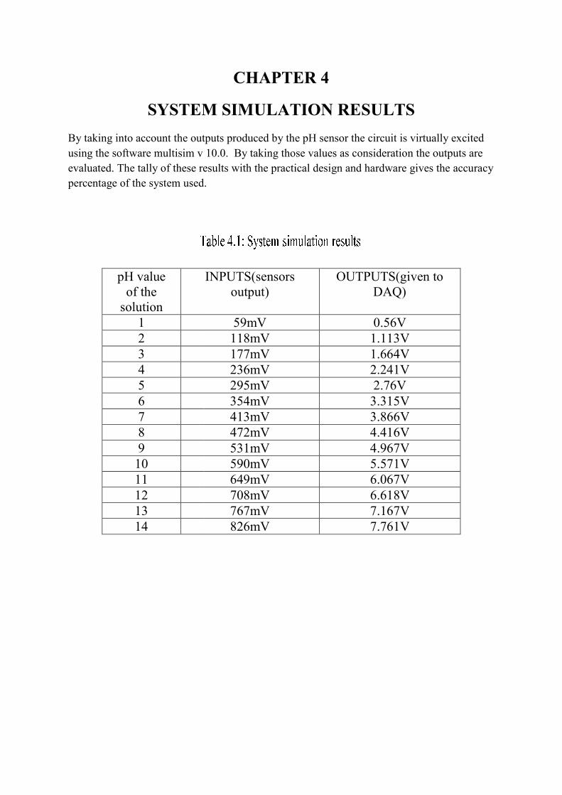
SYSTEM SIMULATION RESULTS
By taking into account the outputs produced by the pH sensor the circuit is virtually excited using the software multisim v 10.0. By taking those values as consideration the outputs are evaluated. The tally of these results with the practical design and hardware gives the accuracy percentage of the system used.
pH value of the
solution 1 2 3 4 5 6 7 8 9
10 11 12 13 14
CHAPTER 4
SYSTEM SIMULATION RESULTS
By taking into account the outputs produced by the pH sensor the circuit is virtually excited v 10.0. By taking those values as consideration the outputs are
evaluated. The tally of these results with the practical design and hardware gives the accuracy percentage of the system used.
INPUTS(sensors output)
OUTPUTS(giDAQ)
59mV 0.56V 118mV 1.113V177mV 1.664V236mV 2.241V295mV 2.76V 354mV 3.315V413mV 3.866V472mV 4.416V531mV 4.967V590mV 5.571V649mV 6.067V708mV 6.618V767mV 7.167V826mV 7.761V
SYSTEM SIMULATION RESULTS
By taking into account the outputs produced by the pH sensor the circuit is virtually excited v 10.0. By taking those values as consideration the outputs are
evaluated. The tally of these results with the practical design and hardware gives the accuracy
OUTPUTS(given to
1.113V 1.664V 2.241V
3.315V 3.866V 4.416V 4.967V 5.571V 6.067V 6.618V 7.167V 7.761V

The change of the voltage at the output terminal i.e. 1 changes with the gain of the amplifier. The gain of the amplifier is varied by varying the voltage given to the terminals Vcc+ i.e. pin 4 and GND pin 11.
change of the voltage at the output terminal i.e. 1 changes with the gain of the amplifier. The gain of the amplifier is varied by varying the voltage given to the terminals Vcc+ i.e.
change of the voltage at the output terminal i.e. 1 changes with the gain of the amplifier. The gain of the amplifier is varied by varying the voltage given to the terminals Vcc+ i.e.

CHAPTER 5
HARDWARE DESCRIPTION
The components are connected on a Printed
Circuit Board in the non inverting mode to the operational amplifier as shown in the circuit
diagram. The functioning of the non inverting amplifier is simple. The basic circuit for the
non-inverting operational amplifier is relatively straightforward. In this circuit the signal is
applied to the non-inverting input of the op-amp. However the feedback is taken from the
output of the op-amp via a resistor to the inverting input of the operational amplifier where
another resistor is taken to ground. It is the value of these two resistors that govern the gain of
the operational amplifier circuit. The amplification of the circuit is explained mathematically
as
So according to the circuit every input voltage that is given to the circuit is multiplied by
The supply to the op amp is taken from a 12V, 1.5A DC adapter. The
working of the circuit can be explained by the sequence of changes that occur to the
components of the circuit. Initially the pH probe is dipped in to the solution and the output
terminal of it is connected to the input terminal 3 of the IC LM324 which gets excited when
the supply is given to the terminal 4 and terminal 11 of it. Once the IC is energized it
multipies the input voltage as per the given feedback and grounding resistance of it as per the
equation stated above. The pH sensor and the amplifier circuit gets connected and the mV
generated by the pH sensor is taken by the IC and the output is read at terminal 1 of the IC.
This is given as input to the DAQ card that is used, the range of control of pH that has
transformed itself into volts is set by programming the DAQ by setting the limits using the
software LABVIEW. The output of the DAQ card is connected to the motors that drive the
acid container and base container. Once the output of the amplifier circuit is beyond the
voltage limit (which indeed is the pH limit) in either way the corresponding motor will start
running. Say if the pH limits set are 3.5 V and 5 V i.e. from 6 pH to 9 pH, then if the
amplifier output voltage exceeds 5
so the acid motor is given supply and the pH value gets reduced. The opposite happens if the
voltage generated by the amplifier is less than 3.5 V. Thus the control of pH of the solution is
automated whenever it misses its range of control. The hardware designed even as it looks
simple does an important job of controlling the pH of a solution.
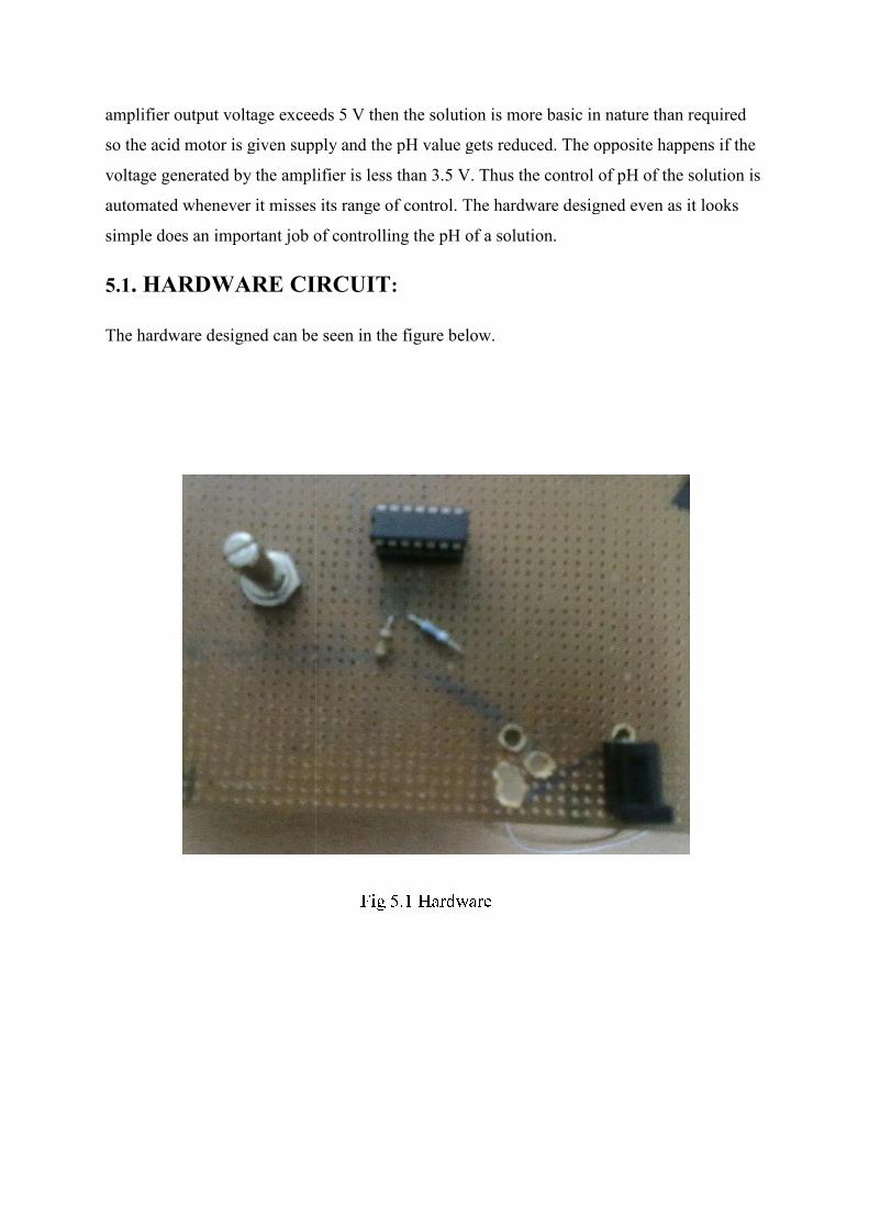
5.1. HARDWARE CIRCUIT
The hardware designed can be seen in the figure below.
amplifier output voltage exceeds 5 V then the solution is more basic in nature than required
so the acid motor is given supply and the pH value gets reduced. The opposite happens if the
voltage generated by the amplifier is less than 3.5 V. Thus the control of pH of the solution is
ed whenever it misses its range of control. The hardware designed even as it looks
simple does an important job of controlling the pH of a solution.
. HARDWARE CIRCUIT:
The hardware designed can be seen in the figure below.
V then the solution is more basic in nature than required
so the acid motor is given supply and the pH value gets reduced. The opposite happens if the
voltage generated by the amplifier is less than 3.5 V. Thus the control of pH of the solution is
ed whenever it misses its range of control. The hardware designed even as it looks
CHAPTER 6
SOFTWARE DESCRIPTIONS
The softwares used for the circuit eventually help the user the validity and control of the
circuit. The softwares used for the project are
• MULTISIM
• LABVIEW
6.1. MULTISIM:
Multisim is one such software that helps the user For dete • Generate mathematical models of electronic components. • Test performance without actually building the circuit . • Calculating parameters of non-linear devices. • To test the validity of the circuit. Most of the components that are available in the electronic market today are available in the updating versions of multisim. These updated versions consists almost all the components that came into existence into the market after its previous version. Using this software in testing of circuits help us from the burden of practical building up of circuits.
6.1.2 Use of Multisim in the Project:
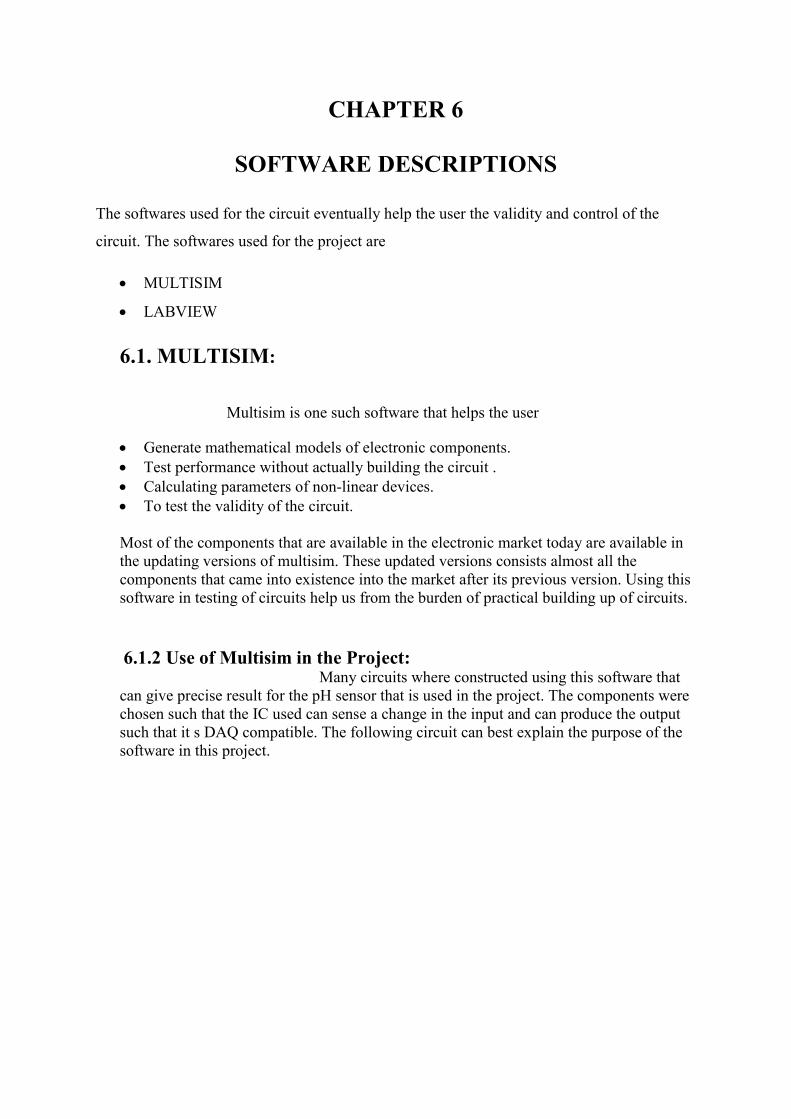
Many circuits where constructed using this software that can give precise result for the pH sensor that is used in the project. The components were chosen such that the IC used can sense a change in the input and can produce the output such that it s DAQ compatible. The following circuit can best explain the purpose of the software in this project.
Calculating parameters of non-linear devices
The maximum permissible voltage that a DAQ can take is 10V s
maximum voltage that is to be given to the circuit to 8V.
The maximum permissible voltage that a DAQ can take is 10V so the circuit limits the
maximum voltage that is to be given to the circuit to 8V.
o the circuit limits the

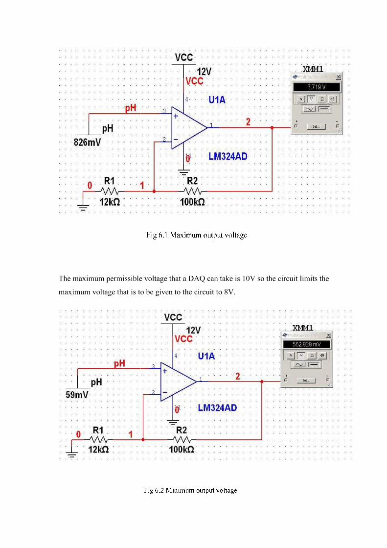
The minimum change in the voltage that a DAQ can sense is 135mV the initial output that
the amplifier circuit gives is almost thrice the minimum sensible voltage.
The purpose of the software in the project played a major role in deciding the components
that are to be used for the project.
6.2. LabVIEW:
LabVIEW is the software that is used for graphical programming of a system. LabVIEW (short for Laboratory Virtual Instrumentation Engineering Workbench) is a platform and development environment for avisual programming language from National Instruments. The purpose of such programming is automating the usage of processing and measuring equipment in any laboratory setup.
LabVIEW ties the creation of user interfaces (called front panels) into the development cycle. LabVIEW programs/subroutines are called virtual instruments (VIs). Each VI has three components: a block diagram, a front panel and a connector panel. The last is used to represent the VI in the block diagrams of other, calling VIs. Controls and indicators on the front panel allow an operator to input data into or extract data from a running virtual instrument. However, the front panel can also serve as a programmatic interface. Thus a virtual instrument can either be run as a program, with the front panel serving as a user interface, or, when dropped as a node onto the block diagram, the front panel defines the inputs and outputs for the given node through the connector pane. This implies each VI can be easily tested before being embedded as a subroutine into a larger program.
The graphical approach also allows non-programmers to build programs by dragging and dropping virtual representations of lab equipment with which they are already familiar. The LabVIEW programming environment, with the included examples and the documentation, makes it simple to create small applications. This is a benefit on one side, but there is also a certain danger of underestimating the expertise needed for good quality "G" programming. For complex algorithms or large-scale code, it is important that the programmer possess an extensive knowledge of the special LabVIEW syntax and the topology of its memory management. The most advanced LabVIEW development systems offer the possibility of building stand-alone applications. Furthermore, it is possible to create distributed applications, which communicate by a client/server scheme, and are therefore easier to implement due to the inherently parallel nature of G-code.
The other benefits of LabVIEW are stated below
• Interfacing
• Code compilation
• Recoding
• Code re-use

6.2.1 Use of LabVIEW in the Project:
The use of LabVIEW in this project is explained below:
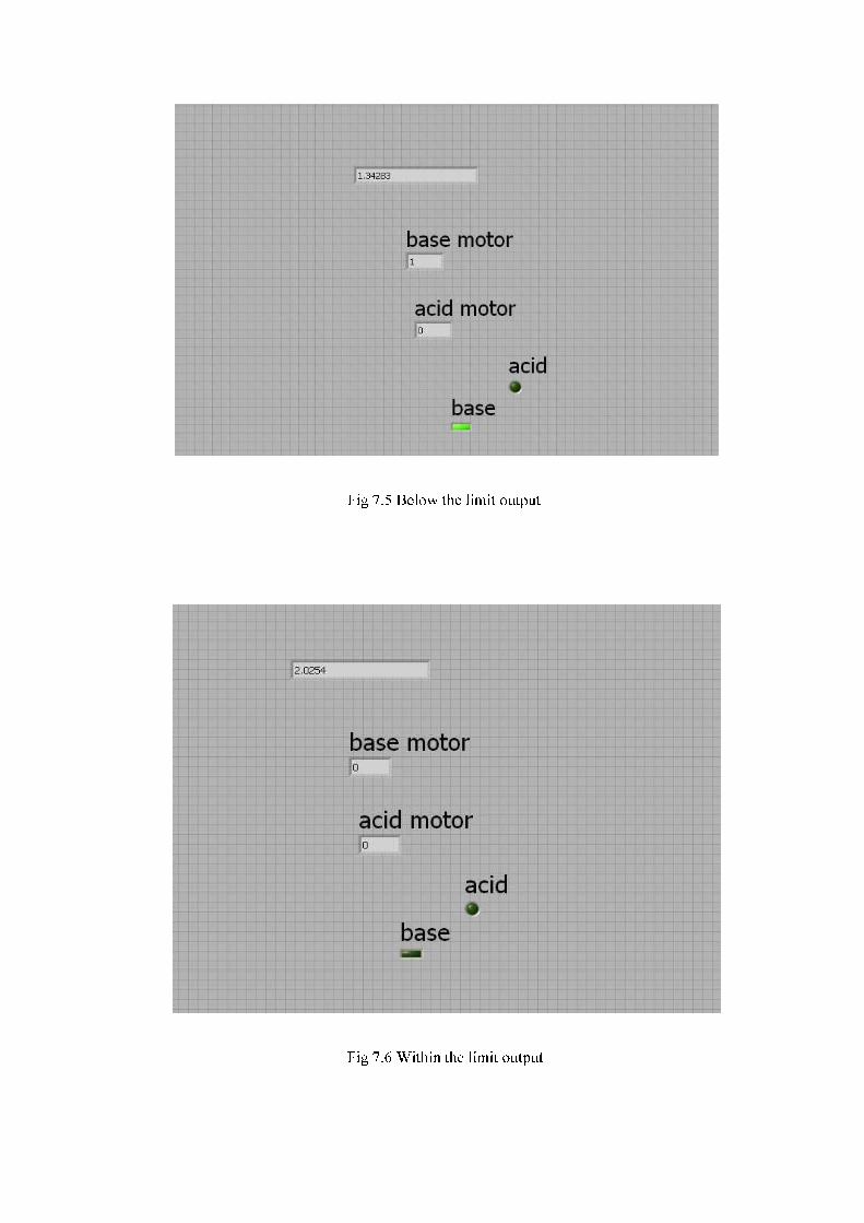
As we see from the figure above the output that is produced by the amplifier circuit is
given to the DAQ which is represented as DAQ assistant. This output is given to an adder
that increases the value as for the voltage can represent the pH on the compute
voltage is given to two controllers which set limits the outputs that are produced by the
controller if exceed the limit the corresponding LED glows.
6.2.2 Interfacing With DAQ
The sequence of programming a DAQ is well unders
steps.
a) First the output of the circuit is to be connected to the analog terminals of
the DAQ as per the terminology given on DAQ.
b) Connect the DAQ to the PC with the USB connector given. See if the light of the
DAQ is blinking.
n the Project:
The use of LabVIEW in this project is explained below:
As we see from the figure above the output that is produced by the amplifier circuit is
given to the DAQ which is represented as DAQ assistant. This output is given to an adder
that increases the value as for the voltage can represent the pH on the compute
voltage is given to two controllers which set limits the outputs that are produced by the
controller if exceed the limit the corresponding LED glows.
With DAQ:
The sequence of programming a DAQ is well understood if explained in
First the output of the circuit is to be connected to the analog terminals of
the DAQ as per the terminology given on DAQ.
Connect the DAQ to the PC with the USB connector given. See if the light of the
As we see from the figure above the output that is produced by the amplifier circuit is
given to the DAQ which is represented as DAQ assistant. This output is given to an adder
that increases the value as for the voltage can represent the pH on the computer. This
voltage is given to two controllers which set limits the outputs that are produced by the
tood if explained in
First the output of the circuit is to be connected to the analog terminals of
Connect the DAQ to the PC with the USB connector given. See if the light of the

c) Open the LabVIEW software and go to the subroutine called DAQ that is to be
installed before starting of the project.
d) Follow the user interface window that gets displayed. This is highly user friendly.
e) We need to receive the output which is in the form of voltage so click on the
corresponding icon buttons displayed.
f) Now the DAQ terminals are displayed and the terminal to which the input is given
is to be selected.
g) Now drop in the component “DAQ assistant” from where the voltages generated
by the amplifier circuit can be viewed.
h) Further the output that is obtained from the “DAQ assistant” can be programmed
graphically as per the requirement.

OUTPUTS OBSERVED
CHAPTER 7
OUTPUTS OBSERVED

Practical voltage outputs are noted after interfacing the DAQ with the circuit
pH of the
solution
pH sensor
output
1 59mV
2 118mV
3 177mV
4 236mV
5 295mV
6 354mV
7 413mV
8 472mV
9 531mV
10 590mV
11 649mV
12 708mV
13 767mV
14 826mV
Practical voltage outputs are noted after interfacing the DAQ with the circuit
pH sensor
output
Amplifier
output
Acid motor
LED
59mV 539mV OFF
118mV 1.065V OFF
177mV 1.61V OFF
236mV 2.15V OFF
295mV 2.59V OFF
354mV 3.13V OFF
413mV 3.65V OFF
472mV 4.25V ON
531mV 4.70V ON
590mV 5.92V ON
649mV 5.89V ON
708mV 6.42V ON
767mV 6.98V ON
826mV 7.64V ON
Practical voltage outputs are noted after interfacing the DAQ with the circuit
Base motor
LED
ON
ON
ON
OFF
OFF
OFF
OFF
OFF
OFF
OFF
OFF
OFF
OFF
OFF

CHAPTER 8
CONCLUSION AND SCOPE FOR FUTURE WORK
8.1 CONCLUSION:
The input voltage to the amplifier circuit is given from a pH sensor that
generated a voltage in the order of mV for the change in pH that occurs in the solution.
This voltage is amplified by the amplifier circuit to range where the output of the
amplifier circuit is adaptable by the DAQ card that is being used.
The requirements of the range of control of pH is to be observed and
the programming in the labview is to be executed by keeping in to view the circuit output
production chart.
The pH value can be easily controlled between varied ranges of values
just by changing the limits used in the software to program the DAQ. This project is practical
and highly feasible in economic point of view, and has an advantage of controlling the pH
value in a wide range. This project is an automated, reliable and adaptable way of controlling
the pH value in a bioreactor.
8.2 SCOPE FOR FUTURE DEVELOPMENTS:
This pH control can be adapted in industries where
the cleaning and drying of machine parts in the acids exist. Further for making this adaptive
for factories the control part of the project can be made cheaper by using a pair of
comparators that set the limits of control instead of using a DAQ. This amendment in the
circuit will minimize the cost of pH control and efficiency of the circuit also remains
satisfactory.

REFERENCES
BOOKS:
• Op Amp Applications Handbook, Analog Devices, Inc., edited by Walt Jorg.
• LabVIEW™ for Data Acquisition,By: Bruce Mihura, Publisher: Prentice Hall
• pH Sensors and Meters for Laboratory and Process Applications, By John Turner
WEBSITES:
• http://www.sensorland.com/HowPage037.html
• http://en.wikipedia.org/wiki/Data_acquisition
• http://www.national.com/mpf/LM/LM324.html#Overview
• http://www.alldatasheet.com/
• http://www.electronics-tutorials.ws/opamp/opamp_3.html

APPENDIX – A
LIST OF COMPONENTS
Type of the component Name of the component No.of components
Integrated Circuit LM324 1
Resistors 12KΩ, 100KΩ 1
Adapter 230VAC to 12V, 1.5A
DC
1
DAQ 6009 1
pH sensor DpH500 1
Programming software
with a compatible
computer
LabVIEW v 7.0.2 1
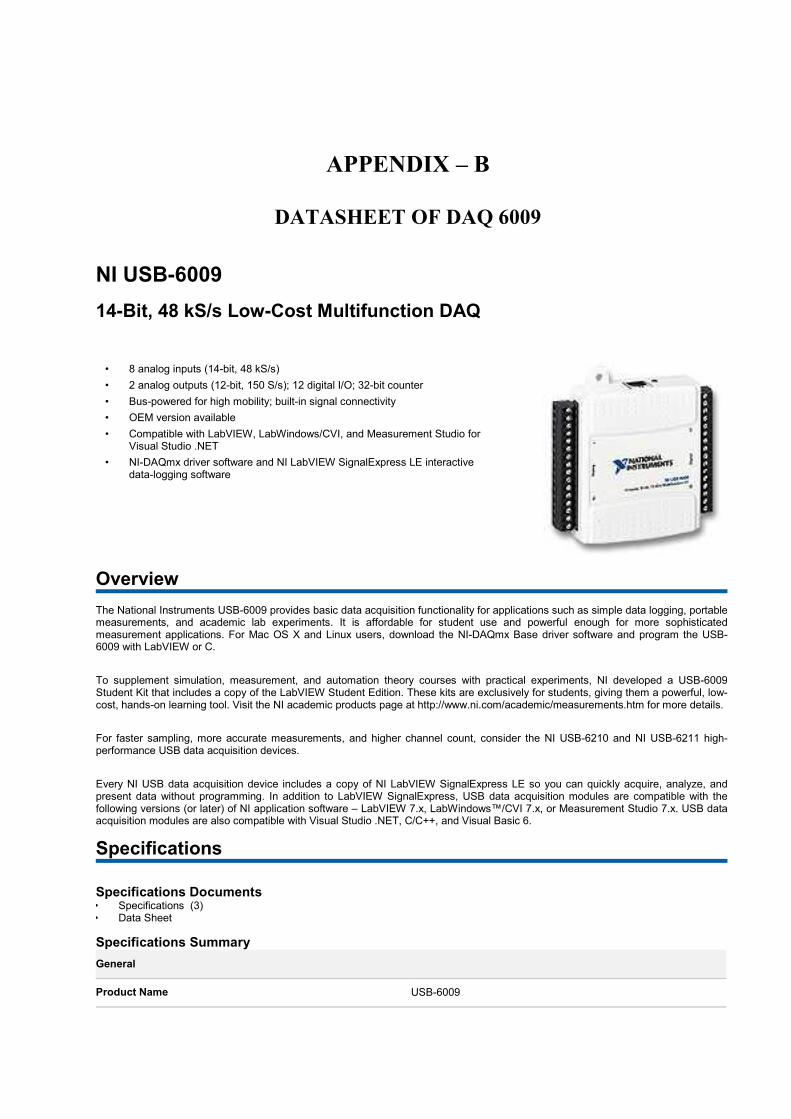
APPENDIX – B
DATASHEET OF DAQ 6009
NI USB-6009
14-Bit, 48 kS/s Low-Cost Multifunction DAQ
• 8 analog inputs (14-bit, 48 kS/s)
• 2 analog outputs (12-bit, 150 S/s); 12 digital I/O; 32-bit counter
• Bus-powered for high mobility; built-in signal connectivity
• OEM version available
• Compatible with LabVIEW, LabWindows/CVI, and Measurement Studio for Visual Studio .NET
• NI-DAQmx driver software and NI LabVIEW SignalExpress LE interactive data-logging software
Overview
The National Instruments USB-6009 provides basic data acquisition functionality for applications such as simple data logging, portable measurements, and academic lab experiments. It is affordable for student use and powerful enough for more sophisticated measurement applications. For Mac OS X and Linux users, download the NI-DAQmx Base driver software and program the USB-6009 with LabVIEW or C.
To supplement simulation, measurement, and automation theory courses with practical experiments, NI developed a USB-6009 Student Kit that includes a copy of the LabVIEW Student Edition. These kits are exclusively for students, giving them a powerful, low-cost, hands-on learning tool. Visit the NI academic products page at http://www.ni.com/academic/measurements.htm for more details.
For faster sampling, more accurate measurements, and higher channel count, consider the NI USB-6210 and NI USB-6211 high-performance USB data acquisition devices.
Every NI USB data acquisition device includes a copy of NI LabVIEW SignalExpress LE so you can quickly acquire, analyze, and present data without programming. In addition to LabVIEW SignalExpress, USB data acquisition modules are compatible with the following versions (or later) of NI application software – LabVIEW 7.x, LabWindows™/CVI 7.x, or Measurement Studio 7.x. USB data acquisition modules are also compatible with Visual Studio .NET, C/C++, and Visual Basic 6.
Specifications
Specifications Documents • Specifications (3) • Data Sheet
Specifications Summary
General
Product Name USB-6009

Product Family Multifunction Data Acquisition
Form Factor USB
Part Number 779026-01
Operating System/Target Windows , Linux , Mac OS , Pocket PC
DAQ Product Family B Series
Measurement Type Voltage
RoHS Compliant Yes
Analog Input
Channels 8 , 4
Single-Ended Channels 8
Differential Channels 4
Resolution 14 bits
Sample Rate 48 kS/s
Throughput 48 kS/s
Max Voltage 10 V
Maximum Voltage Range -10 V , 10 V
Maximum Voltage Range Accuracy 138 mV
Minimum Voltage Range -1 V , 1 V
Minimum Voltage Range Accuracy 37.5 mV
Number of Ranges 8
Simultaneous Sampling No
On-Board Memory 512 B
Analog Output
Channels 2
Resolution 12 bits
Max Voltage 5 V
Maximum Voltage Range 0 V , 5 V
Maximum Voltage Range Accuracy 7 mV
Minimum Voltage Range 0 V , 5 V
Minimum Voltage Range Accuracy 7 mV
Update Rate 150 S/s
Current Drive Single 5 mA

Current Drive All 10 mA
Digital I/O
Bidirectional Channels 12
Input-Only Channels 0
Output-Only Channels 0
Number of Channels 12 , 0 , 0
Timing Software
Logic Levels TTL
Input Current Flow Sinking , Sourcing
Output Current Flow Sinking , Sourcing
Programmable Input Filters No
Supports Programmable Power-Up States? No
Current Drive Single 8.5 mA
Current Drive All 102 mA
Watchdog Timer No
Supports Handshaking I/O? No
Supports Pattern I/O? No
Maximum Input Range 0 V , 5 V
Maximum Output Range 0 V , 5 V
Counter/Timers
Counters 1
Buffered Operations No
Debouncing/Glitch Removal No
GPS Synchronization No
Maximum Range 0 V , 5 V
Max Source Frequency 5 MHz
Minimum Input Pulse Width 100 ns
Pulse Generation No
Resolution 32 bits
Timebase Stability 50 ppm
Logic Levels TTL
Physical Specifications

Length 8.51 cm
Width 8.18 cm
Height 2.31 cm
I/O Connector Screw terminals
Timing/Triggering/Synchronization
Triggering Digital
Synchronization Bus (RTSI) No
Pricing
Are you looking for order or quoting information? Select the country where you will use the product so that we can provide accurate pricing, availability and purchasing information.
NI USB-6009 Complete Package Each NI USB-6009 requires:
NI USB-6009 Software
Roll over icons above to learn why you need each item in the package.
NI USB-6009 and Accessories Select Your Country
NI USB-6009 - 779026-01 For price, Select Your Country
Optional Accessories Hide
USB 6008/09 Accessory Kit - 779371-01
For price, Select Your Country
USB 6000 Series Prototyping Accessory - 779511-01
For price, Select Your Country
Software Select Your Country Note : You should only purchase this device without software if you already own compatible application software.
NI LabVIEW SignalExpress - 779037-35 For price, Select Your Country
You need software to interface with your hardware and to collect, analyze, present, and store your measurements. This board is compatible with a variety of programming languages, including LabVIEW, C/C++, Visual Basic, and .NET. LabVIEW provides the easiest integration with all of your NI hardware and is recommended to maximize your hardware investment. Please select the country where you will use the product(s) so that we can provide you with accurate pricing, availability, and purchasing information

Services
Extended Warranties
National Instruments designs and manufactures all products to minimize failures, however unexpected failures can still occur. Extended warranties provide a fixed economical price at the time of system purchase, covering any repair costs for up to three years. In addition, they offer the following benefits: • Significant cost savings compared to individual repair incidents • Fault location, diagnostics, and repair by NI any time the system product fails • All parts and labor costs covered as well as any adjustments needed to restore the hardware to manufacturing specifications For more information about your warranty options: • Learn More About Warranty Services [http://www.ni.com/services/warranty.htm] • Talk to an Expert About Extended Warranties [javascript:openCallMeWindowCTA(document.referrer,%20’US’)] • View Warranty Repair Policies [http://www.ni.com/services/warranty_repair_policies.htm]
Calibration
NI recognizes the need to maintain properly calibrated devices for high-accuracy measurements. NI provides manual calibration procedures, services to recalibrate your products, and automated calibration software to calibrate many NI measurement products. • Learn More About Calibration Services [http://www.ni.com/services/calibration.htm]
Training
NI training is the fastest, most certain route to productivity with NI tools and successful application development. • Learn More About NI Training and Certification [http://www.ni.com/training/] • Find a Course Near You and View Schedules [http://sine.ni.com/apps/utf8/nisv.custed]
Repair Services
Return your registered product under warranty at no additional labor and parts cost. NI offers fault location, diagnostics, and repair any time the system fails as well as any adjustments needed to restore the hardware to manufacturing specifications. • Learn More About Repair Services [http://www.ni.com/services/warranty.htm] • Contact NI to obtain a Return Material Authorization (RMA) form and shipping instructions.
[http://sine.ni.com/apps/utf8/nicc.call_me] • View your RMA support request status online. [http://www.ni.com/support/servicereq/] • Register your product [http://www.ni.com/register] .
Technical Support
ni.com/support [http://www.ni.com/support/]
Resources
Additional Product Information • Manuals (4) • Dimensional Drawings (2) • Product Certifications
Related Information • NI USB Data Acquisition for OEM • Download NI Data Acquisition Drivers • NI LabVIEW SignalExpress Interactive Data-Logging Software

APPENDIX – C
DATASHEET OF IC LM324


![A Practical Approach To pH Control: Observations …A Practical Approach to pH Control Brice Poston 9/1/13 4:50 PM Formatted... [1] A Practical Approach To pH Control: Observations](https://img.pdfslide.us/doc/110x75/5f07ac7f7e708231d41e2a68/a-practical-approach-to-ph-control-observations-a-practical-approach-to-ph-control.jpg)