Embed Size (px)
Citation preview
PH 212 07-31-2015
Physics 212 Exam-3
Solution NAME: _____________________________________
Write down your name also on the back of the package of sheets you turn in.
SIGNATURE and ID: ___________________________ Return this hard copy exam together with your other answer sheets. There are four questions, which are worth 110 points.
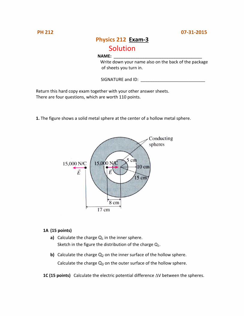
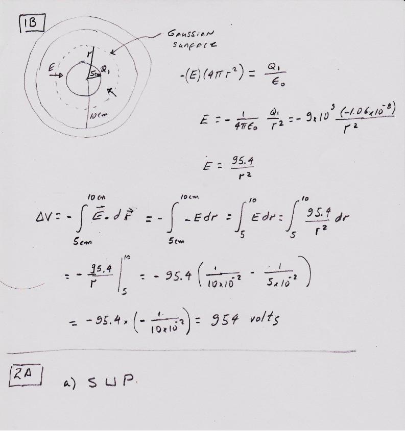
1. The figure shows a solid metal sphere at the center of a hollow metal sphere.
P
1A (15 points)
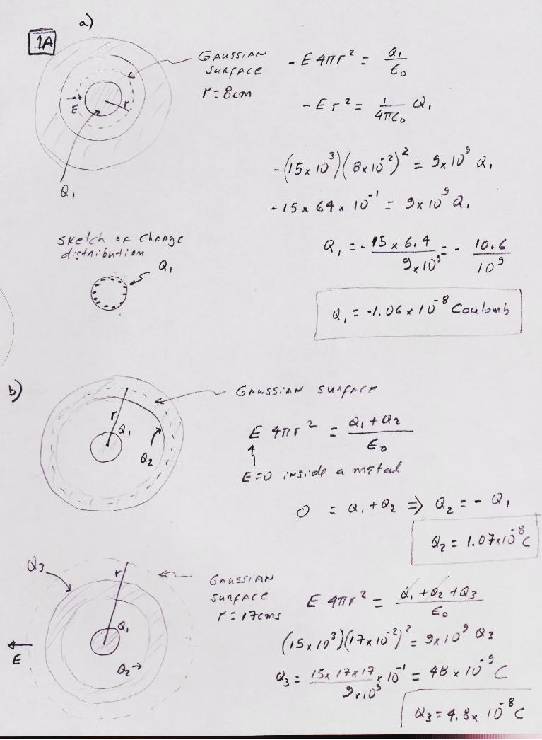
a) Calculate the charge Q1 in the inner sphere.
Sketch in the figure the distribution of the charge Q1.
b) Calculate the charge Q2 on the inner surface of the hollow sphere.
Calculate the charge Q3 on the outer surface of the hollow sphere.
1C (15 points) Calculate the electric potential difference V between the spheres.
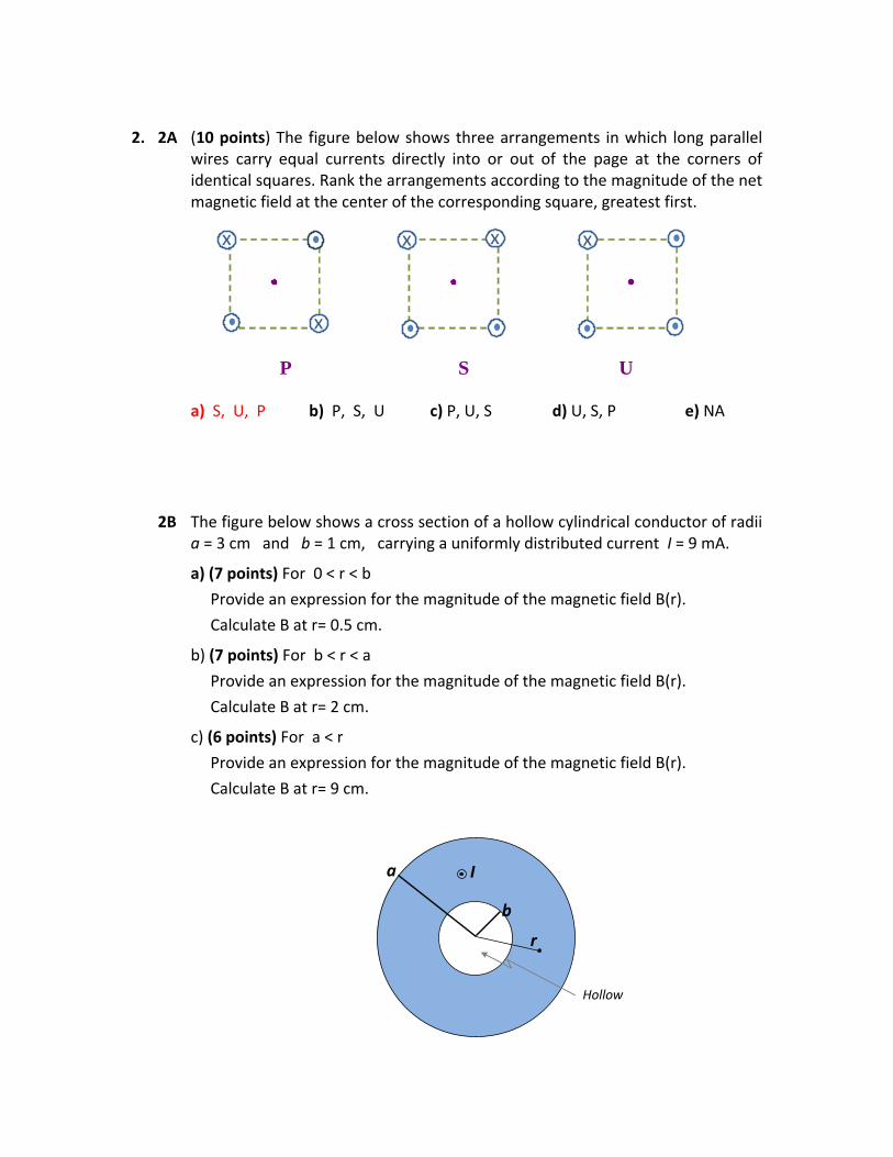
2. 2A (10 points) The figure below shows three arrangements in which long parallel
wires carry equal currents directly into or out of the page at the corners of identical squares. Rank the arrangements according to the magnitude of the net magnetic field at the center of the corresponding square, greatest first.
P S U
x
x
x
x
x
a) S, U, P b) P, S, U c) P, U, S d) U, S, P e) NA
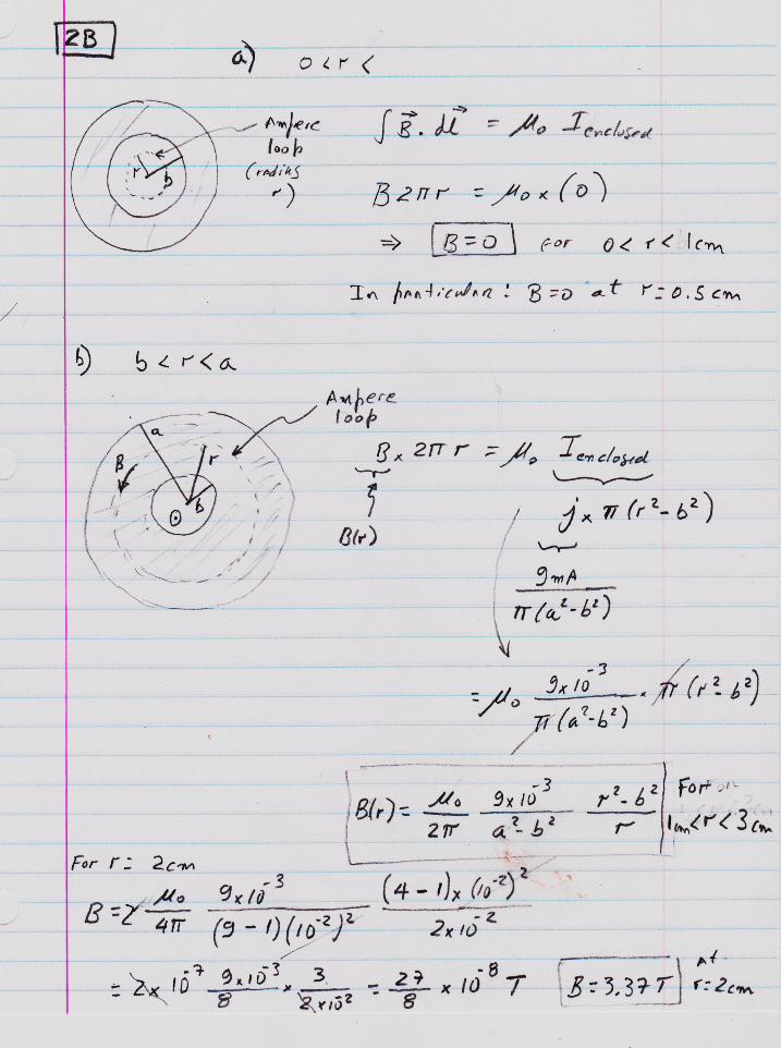
2B The figure below shows a cross section of a hollow cylindrical conductor of radii a = 3 cm and b = 1 cm, carrying a uniformly distributed current I = 9 mA.
a) (7 points) For 0 < r < b
Provide an expression for the magnitude of the magnetic field B(r).
Calculate B at r= 0.5 cm.
b) (7 points) For b < r < a
Provide an expression for the magnitude of the magnetic field B(r).
Calculate B at r= 2 cm.
c) (6 points) For a < r
Provide an expression for the magnitude of the magnetic field B(r).
Calculate B at r= 9 cm.
b
a
Q1= - 3 C
Hollow
r
I
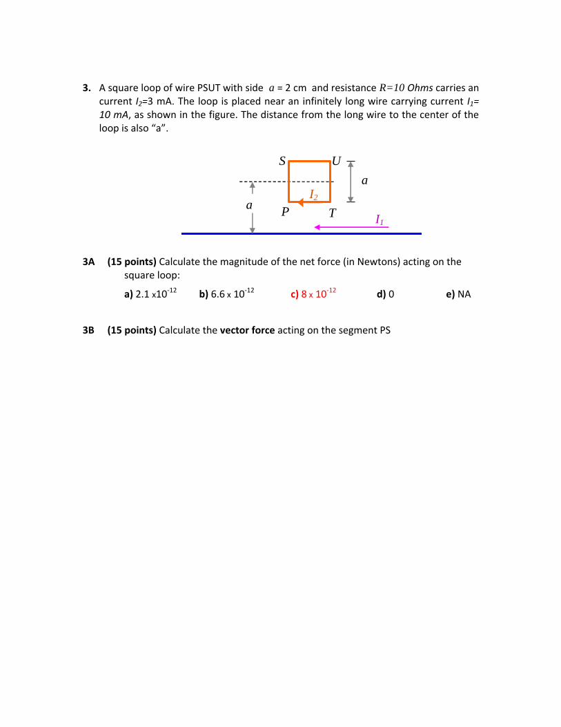
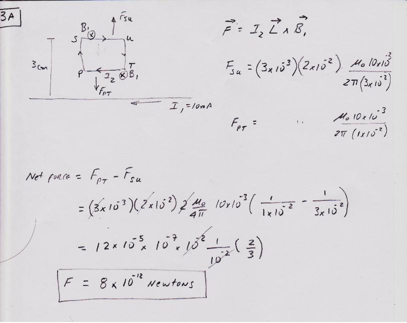
3. A square loop of wire PSUT with side a = 2 cm and resistance R=10 Ohms carries an current I2=3 mA. The loop is placed near an infinitely long wire carrying current I1= 10 mA, as shown in the figure. The distance from the long wire to the center of the loop is also “a”.
a
a
I1
I2
P
S U
T
3A (15 points) Calculate the magnitude of the net force (in Newtons) acting on the square loop:
a) 2.1 x10⁻¹² b) 6.6 x 10⁻¹² c) 8 x 10-12 d) 0 e) NA
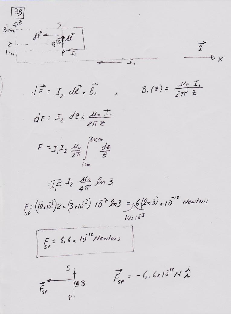
3B (15 points) Calculate the vector force acting on the segment PS

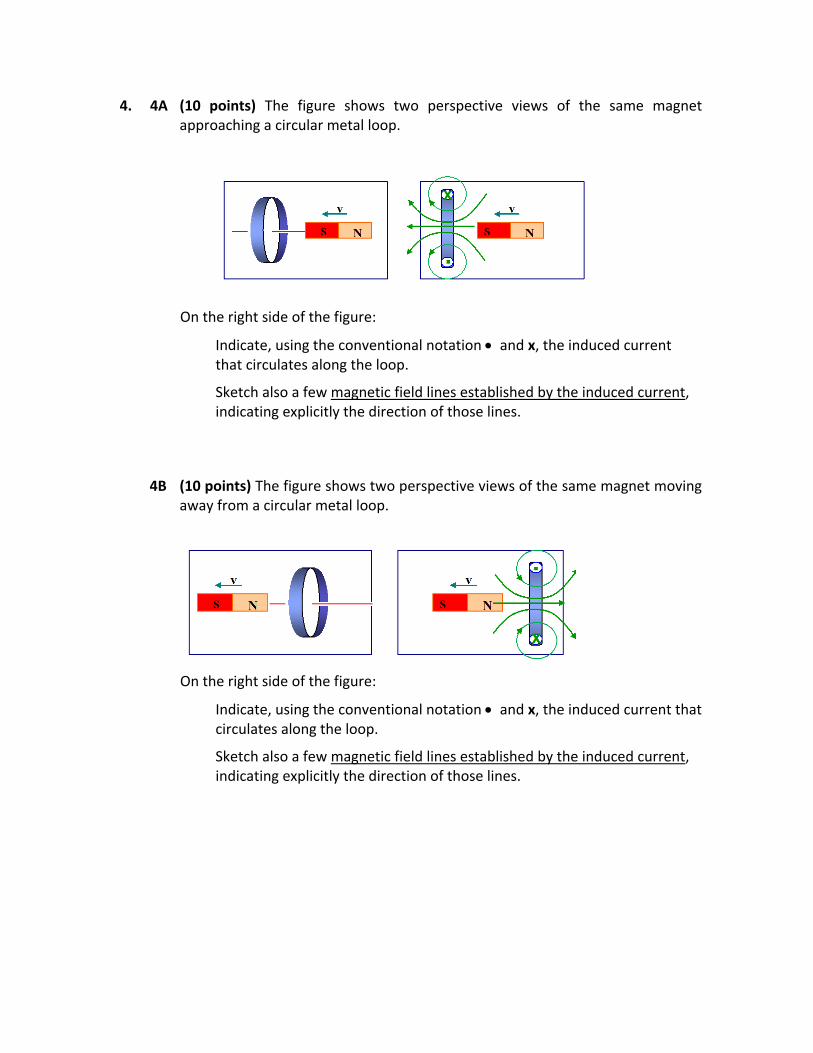
4. 4A (10 points) The figure shows two perspective views of the same magnet approaching a circular metal loop.
On the right side of the figure:
Indicate, using the conventional notation and x, the induced current that circulates along the loop.
Sketch also a few magnetic field lines established by the induced current, indicating explicitly the direction of those lines.
4B (10 points) The figure shows two perspective views of the same magnet moving away from a circular metal loop.
On the right side of the figure:
Indicate, using the conventional notation and x, the induced current that circulates along the loop.
Sketch also a few magnetic field lines established by the induced current, indicating explicitly the direction of those lines.
Some helpful formulas:
nano
mm = 10-3 m
Centripetal force = m v2/ r
mass of electron: 9.109 x 10⁻³¹ kg 2
212
0Nm
C1085.8
1 eV = 1.602 x 10⁻¹⁹ J o = 4 10-7 Tm/A = 1.2 x 10⁻⁶ Tm/A
Coulomb's Law: ur
qqF
2
12
04
1
, where
2
29
0 C
Nm1099.8
4
1
2
212
0Nm
C1085.8
Electric field, along the z-axis, due to a charge Q distributed uniformly along a thin ring of radius
R.:
kR
QE ˆ
4
12/322
0
z
z
Electric field established by an infinite and uniformly charged sheet: E = /2o
Gauss' Law
= S
sdE
= q /o, where q is the net charge inside the Gaussian surface.
Potential energy difference
UB - UA ≡ Wext (A
extF B)
Work done by the external force to take the particle from A to B at constant speed
Definition of the Electric Potential 0
)()( 0
q
rWrV
qext
Electric potential difference 0
)(0
q
BAWVV
qext
AB
0q
AB UU
Potential difference sdEVVB
AAB
Electric potential due to a point charge q:
r
qV
04
1
Relationship between E and V: Ex = - dV/dx
About capacitance
Q = C V
For a parallel-plate capacitor C = Ao /d
U = CV2 / 2 = Q2 / 2 C
Capacitors connected in parallel Cequiv = C1 + C2 + C3
Capacitors connected in series 1/Cequiv = (1/C1) + (1/C2) +(1/C3)
sincossin dCosd
MAGNETISM
BF
vq
F = force, q = charge, v = velocity, B = magnetic field
1 Tesla = 104 gauss
rvB
x4 3
0
r
q
Magnetic field produced by a charge q that moves with velocity v
o = 4 x 10⁻⁷ Tm/A = 1.2 x 10⁻⁶ Tm/A
rB
x d4 3
0 lr
Id
Magnetic field produced by a small segment dl carrying a current I.
= L i = Magnetic flux, L = inductance, i = current
Inductive reactance XL = L
B
0 I
4
1
R Magnetic field at the center of a semi-circle of radius "R"
B 0 I
4 R Magnetic field at the center of an arc of angle f (in radians) and radius
"R".
B 0 I
2 r Magnetic field produced by a infinitely long wire at a distance "r" from it.
BlF
x I Force on a current I due to an external magnetic field B
.
F
L 0
IaI b
2 d Force per unit length between two parallel long wires, carrying currents Ia
and Ib respectively, separated by a distance "d"
Faraday's Law t
,
where = Magnetic flux and = electromotive force
Definition of the magnetic dipole moment of a loop of area A, carrying a current I: = I A n
where A = area, I current, n = unit vector perpendicular to the loop