Embed Size (px)
Citation preview

PGRemoteForP338 User’s Guide Supplement – Doc. Rev. 1.5 -- 6/14/13
- Page i -
PGRemoteForP338 User’s Guide Supplement

PGRemoteForP338 User’s Guide Supplement – Doc. Rev. 1.5 -- 6/14/13
- Page ii -
Table of Contents1 Overview ..................................................................................................................... 1
1.1 Introduction....................................................................................................... 1
1.2 Summary of New Features............................................................................... 1
1.3 Terminology....................................................................................................... 3
2 P338 Probe Description ............................................................................................. 4
2.1 PG Inputs........................................................................................................... 4
2.2 MIPI Link Outputs ........................................................................................... 5
2.3 Other P338 I/O .................................................................................................. 5
3 Setup & Installation................................................................................................... 7
3.1 Install PGAppDotNet........................................................................................ 7
3.2 Install PGRemoteForP338 ............................................................................... 7
3.3 Setup PG Module(s).......................................................................................... 8 3.3.1 Dual-PG setup............................................................................................. 8 3.3.2 Single PG setup........................................................................................... 8
3.4 Setup P338 Probe .............................................................................................. 9
3.5 Power-On PG Modules and P338.................................................................... 9
3.6 Launch PGAppDotNet and connect to PG module(s) ................................... 9
3.7 Launch PGRemoteForP338 and connect to PGAppDotNet ....................... 10
4 Using PGRemoteForP338 ....................................................................................... 11
4.1 Overview .......................................................................................................... 11
4.2 GUI Changes and Improvements .................................................................. 11 4.2.1 Main Window ........................................................................................... 11
4.2.1.1 Test Pattern Support.............................................................................. 12 4.2.1.2 Support for Additional Source Image File Formats.............................. 14 4.2.1.3 Image Viewing Dialog.......................................................................... 14 4.2.1.4 Automatic Image Scaling...................................................................... 14 4.2.1.5 Hierarchical PktType Selection ............................................................ 14 4.2.1.6 Component Command Naming in Macros ........................................... 15 4.2.1.7 New Command Button Pages ............................................................... 15 4.2.1.8 Command Button Tooltips.................................................................... 15 4.2.1.9 Expanded Status Display ...................................................................... 15 4.2.1.10 PG Memory Usage Indication .......................................................... 16 4.2.1.11 Expanded DUT Response Viewing .................................................. 16
4.2.2 PG Configuration Dialog .......................................................................... 17 4.2.3 Timing Dialog........................................................................................... 19 4.2.4 Video Decimation/Expansion Dialog ....................................................... 20
4.2.4.1 Algorithm Description .......................................................................... 21

Moving Pixel Company PGRemoteForP338 Supplement – Doc. Rev. 1.5 -- 6/14/13
- Page ii -
4.2.4.2 Specifying the Source Image Size: ....................................................... 22 4.2.4.3 Specifying the Duplication Factors:...................................................... 22 4.2.4.4 Supported Video Formats ..................................................................... 22 4.2.4.5 Raw Mode Behavior: ............................................................................ 23 4.2.4.6 Examples:.............................................................................................. 23
4.2.5 Trigger Control Dialog ............................................................................. 23 4.2.5.1 Configuring for Auto-Frame Advance.................................................. 24 4.2.5.2 Configuring for Manual-Frame Advance ............................................. 25 4.2.5.3 Sending Trigger Pulses ......................................................................... 25 4.2.5.4 Troubleshooting Frame Advance Modes.............................................. 25
4.2.6 GUI Options Dialog.................................................................................. 26 4.2.7 Firmware Update Dialog........................................................................... 26 4.2.8 Color Dialog.............................................................................................. 28 4.2.9 Menus........................................................................................................ 28 4.2.10 RPC........................................................................................................... 30
4.3 PGRemoteForP338 Operation....................................................................... 33 4.3.1 Setting the P338 Operating Configuration................................................ 33 4.3.2 Setting the Dual-Interface Mode for Video .............................................. 34 4.3.3 Setting Video Timing Parameters............................................................. 35 4.3.4 WriteMemory Configuration .................................................................... 35 4.3.5 Specifying Image Filenames..................................................................... 36 4.3.6 Sending Non-video Commands ................................................................ 37 4.3.7 Command Insertion................................................................................... 37

Moving Pixel Company PGRemoteForP338 Supplement – Doc. Rev. 1.5 -- 6/14/13
- Page iii -
Table of FiguresFigure 1 – P338 Rear Panel ................................................................................................ 4 Figure 2 – P338 Front Panel ............................................................................................... 5 Figure 3 – GPIO Connector ................................................................................................ 6 Figure 4 – Main Window.................................................................................................. 12 Figure 5 – Test Pattern Syntax Dialog.............................................................................. 13 Figure 6 – DUT Response Dialog..................................................................................... 17 Figure 7 – PG Configuration Dialog................................................................................. 18 Figure 8 – Frame Timing Dialog ...................................................................................... 19 Figure 9 – Video Decimation/Expansion Dialog.............................................................. 21 Figure 10 – Trigger Control Dialog .................................................................................. 24 Figure 11 – GUI Options Dialog ...................................................................................... 26 Figure 12 – USB Connection Dialog ................................................................................ 27 Figure 13 – Firmware Update Dialog ............................................................................... 27 Figure 14 – Color Dialog .................................................................................................. 28

Moving Pixel Company PGRemoteForP338 Supplement – Doc. Rev. 1.5 -- 6/14/13
Contacting The Moving Pixel Company Phone +1.503.626.9663 US Pacific Time Zone Fax +1.503.626.9653 US Pacific Time Zone Address The Moving Pixel Company 4905 SW Griffith Drive, Suite 106 Beaverton, Oregon 97005 USA Email [email protected] Web site http://www.movingpixel.com Documentation

Moving Pixel Company PGRemoteForP338 Supplement – Doc. Rev. 1.5 -- 6/14/13
- Page 1 -
1 Overview
1.1 Introduction The P338 probe is the newest MIPI DPhy probe made by the Moving Pixel Company. It is the third-generation probe, based on its predecessors, the P331 and P332 probes. It has 8 data lanes and two clock lane outputs, grouped as two 4-lane DPhy links. When both links are active in dual-interface modes, the P338 can be viewed as two synchronized P332 probes operating at up to 1.6 Gbps per lane. The main purpose of the P338 probe is to provide synchronized video output on its two DPhy links. Frame timing is identical between the two links, but with each link having different source frame data. Options include acquiring source frame data from separate BMP files, or the left/right half or the even/odd pixels from a single BMP file. On the other hand, both links do not always need to be active, and in single-interface modes, the P338 behaves almost identically to one P332 probe. A couple significant improvements in the P338 versus the P332 are that the firmware is updatable in the field and up to 4 KB of DUT response data can be acquired. The purpose of this document is to describe the operation of the P338 probe in conjunction with the new MIPI application software: PGRemoteForP338. As the name implies, this software is a newer, enhanced version of PGRemote that can operate with the P338. Initially, PGRemoteForP338 is intended for exclusive operation with the P338 though, eventually, it is intended to be backward compatible with the P331 and P332 probes as well. Note that this document is a supplement to the PGRemote User’s Manual, which describes PGRemote and P331/P332 operation. It does not contain a complete description of the PGRemoteForP338 application, only its enhancements and differences in operation using the P338.
1.2 Summary of New Features The following summarizes the new features of the P338 probe and PGRemoteForP338 software: P338 Hardware: Provides two synchronous MIPI DPhy links (interfaces), each with 4 data lanes and a clock
lane Can operate with either interface individually in single-interface mode, with behavior and
features nearly identical to the P332 Can operate using both interfaces in dual-interface modes where the interfaces are exactly
synchronized. - Half-rate dual-interface mode: one PG and maximum bit rate of 800 Mbps - Full-rate dual-interface mode: two PGs and a maximum bit rate of 1600 Mbps

Moving Pixel Company PGRemoteForP338 Supplement – Doc. Rev. 1.5 -- 6/14/13
- Page 2 -
Provides option for real-time decimated image expansion to achieve significant image compression during video mode, drastically improving long image sequence download time and PG memory usage.
Provides 4 KB receive buffer for DUT response capture of LP packets Supports MIPI stream and software control over TrigOut signal, including programmable
pulse width. Probe firmware can be updated in the field using USB connection Faster reconfiguration time
PGRemoteForP338: Dual-interface mode support:
- Synchronous video mode output - Dual-interface video construction modes:
Clone: same image out both interfaces Dual-image: different image out each interface Even/odd pixel: every other pixel out each interface Left/right image: left-half and right-half of image out each interface
- x2 and /2 horizontal scaling for easy switching between single and dual interface modes
- Expanded status display per interface Improved Image Support:
- Automatic resizing of input images (in software) to fit display or camera dimensions - Support for additional source image file formats (jpg, png, tiff, gif). - Basic test pattern generation via naming syntax (syntax dialog provided) - Option to preview image files in the GUI
Video Mode Decimation/Expansion Function: - Source image is decimated (subsampled) by integer factors in software and expanded
on-the-fly in the P338. - High compression factor results in much faster download time and greater maximum
frame size or frame sequence count (at the expense of image quality) Extensive TrigOut Control:
- New command (Assert Probe Trig) allows setting/toggling/pulsing TrigOut signal during macro.
- GUI supports pulsing TrigOut with button press. Can be used as manual frame advance signal in video mode.
- Alternatively, auto-frame advance can be enabled for TrigOut during video mode. User sets the frame period for advance.
Improved DUT Response Capture: - Supports capturing/viewing/saving up to 4 KB of DUT response data for each lane 0 - Supports queueing multiple read responses during macros or video-mode - Supports inserting read commands during video-mode
Expanded Command Button Capabilities: - Command buttons organized on 4 tab pages with 30 buttons each. - Buttons can be assigned tooltips.
Dialog Enhancements: - Hierarchical PktType selection

Moving Pixel Company PGRemoteForP338 Supplement – Doc. Rev. 1.5 -- 6/14/13
- Page 3 -
- New firmware update dialog - New color selection dialog for user customizable colors - PG Event Threshold control (for input events) - PG memory usage (in percent) in indicated in status pane - A GUI Option dialog is provided to suppress common warning messages
Extended RPC command syntax to support multiple interfaces.
1.3 Terminology Interface The P338 is considered to have two interfaces, where an interface is analogous to the functionality of one P332 probe. Thus, an interface consists of two input connectors from the PG, internal processing elements, and one 4-lane DPhy link including a clock. The two interfaces are termed as the bottom (master) interface and the top (slave) interface. Descriptively, bottom and top refer to the physical locations of the MIPI DPhy SMA-connector outputs. Active Interface Depending on the mode setting in PGRemote, one or both interfaces can be made active. With a couple exceptions, all active interfaces transmit data on their DPhy links in response to PGRemote commands that send MIPI data.. As described later in this document, BTA signaling and commands inserted during video mode are only sent out one interface, even if both interfaces are active. Note that when an interface is not active, it is quiescent in the LP11 state. Single-PG Configuration When only one PG module is connected to the P338, the probe is said to be in a single-PG configuration. Dual-PG Configuration When two PG modules, merged to form a 2x-wide logical PG via a Hydra cable, are connected to the P338, the probe is said to be in a dual-PG configuration. Single-Interface Mode When only one interface is active (top or bottom), the probe is said to be in a single-interface mode. Dual-Interface Mode When both interfaces are active, the probe is said to be in a dual-interface mode. Several dual-interface modes exists, each pertaining to how video is output on the two links (i.e. Clone, Dual Image, Even/Odd Pixel, Left/Right Image).

Moving Pixel Company PGRemoteForP338 Supplement – Doc. Rev. 1.5 -- 6/14/13
- Page 4 -
2 P338 Probe Description The P338 architecture is similar to the P332, but with expanded input and output connections. Its I/O can be divided into three categories: PG Inputs, MIPI Link Outputs, and Other I/O. The following sections describe these categories in more detail.
2.1 PG Inputs The P338 probe can operate in dual-PG and single-PG configurations. Dual-PG is the standard configuration, which requires two PGs merged to form a 2x-wide logical PG via a Hydra cable. This configuration allows up to a 1.6 Mbps HS frequency. Single-PG operation can also be used, allowing up to a 800 Mbps HS frequency when both interfaces are active. Full-rate (up to 1.6 Mbps) frequencies can still be used when one interface is active. To be clear, both the top and bottom interfaces can be active, even in a single-PG configuration (just at half-rate). Conversely, either of the single-interface modes can be used, even in a dual-PG configuration. Figure 1 shows the rear-panel of the P338. PG input is received via four input connectors labeled “PG1, Conn A”, “PG1, Conn C”, “PG2, Conn A” and “PG2, Conn C”. All four PG inputs always must be connected to a PG module for correct operation of the probe, though there are two possible topologies depending on whether configuring for single-PG or dual-PG operation.
Figure 1 – P338 Rear Panel The labels on the probe are appropriate for dual-PG configuration, indicating the necessary connection that should be made to that source input. Thus, the connections should be made as follows:
Connector labeled “PG1, Conn A’ should be connected to PG1, Conn A. Connector labeled “PG1, Conn C’ should be connected to PG1, Conn C. Connector labeled “PG2, Conn A” should be connected to PG2, Conn A. Connector labeled “PG2, Conn C” should be connected to PG2, Conn C.

Moving Pixel Company PGRemoteForP338 Supplement – Doc. Rev. 1.5 -- 6/14/13
- Page 5 -
Note that PG1 is identified as the master PG module in the dual-PG configurations (i.e. it is the module that sources control signals in the Hydra cable). Alternate connections used when in a single-PG configuration are as follows:
Connector labeled “PG1, Conn A’ should be connected to PG1, Conn A. Connector labeled “PG1, Conn C’ should be connected to PG1, Conn C. Connector labeled “PG2, Conn A” should be connected to PG1, Conn B. Connector labeled “PG2, Conn C” should be connected to PG1, Conn D.
2.2 MIPI Link Outputs Figure 2 shows the front panel of the P338. Two rows of 10 SMA output connectors represent the top and bottom MIPI DPhy links, representing 4 data lanes and a clock for each interface. In single-interface modes, one link -- top or bottom -- will be active and will behave near-identically to a P332 probe (the non-active link will be held in LP11, including its clock lane). In dual-interface modes, both links – top and bottom – will be active. Both links will be synchronous, both in terms of clock timing and protocol state. That is, when one link is transmitting a HS or LP packet, so is the other. Similarly, SOT and EOT transitions on both links are synchronous.
Figure 2 – P338 Front Panel
2.3 Other P338 I/O Other I/O controls on the front panel are:
Trig Out – SMA carrying a trigger out signal (not yet implemented) Clk Out – SMA carrying a clock out signal (not yet implemented) Ref Clk In – SMA to use as a clock in signal (not yet implemented) “Y” LED – yellow LED; blinks during power-on (reserved for future use) “R” LED – red LED: blinks during power-on (reserved for future use)

Moving Pixel Company PGRemoteForP338 Supplement – Doc. Rev. 1.5 -- 6/14/13
- Page 6 -
“G” LED – green LED: blinks during PG input activity; solid-on otherwise Other I/O controls on the read panel are:
DC adapter input LED Indicator that power has been applied USB 2.0 “B” connector, used for updating probe firmware General-purpose I/O connector
Note that the USB connector does not need to be connected for normal operation. It is only needed for firmware update, described later in this document. Figure 3 shows the GPIO connector, similar to the rear-panel connector of the P331/P332 probe, but with some additional GPIO, power, and ground pins. Its signals are:
Evt1 – pulses high when a command is inserted into vertical blanking during video mode
Evt2 – asserts high when any of the four LP contention states are detected GPO0 – reserved general-purpose output GPO1 – reserved general-purpose output GPI0 – reserved general-purpose input GPI1 – reserved general-purpose input Clock Out – clock connection from P338 to the master PG module
The Clock Out signal, as with the P331/P332, must be connected for correct operation. Generally, this connection is made using the two differential wires from the P300 lead-set to the +Clock and –Clock terminals (pins 3 and 4). In the case of a dual-PG configuration, the P300 Inputs probe must be connected to the master PG module (P1).
Figure 3 – GPIO Connector

Moving Pixel Company PGRemoteForP338 Supplement – Doc. Rev. 1.5 -- 6/14/13
- Page 7 -
3 Setup & Installation This document assumes general familiarity with the PG and PGAppDotNet as well as legacy PGRemote operation. If necessary, please refer to the PG Users Manual and PGRemote Users Manual for more information. This section contains abbreviated instructions for installation expressly for P338 operation. For full details for installation and configuration steps common to P331/P332 usage, please refer to the PGRemote Users Manual. Setup Steps:
1. Install PGAppDotNet 2. Install PGRemoteForP338 3. Setup PG module(s) 4. Setup P338 probe 5. Power-on PG module(s) and P338 6. Launch PGAppDotNet and connect to PG module(s) 7. Launch PGRemoteForP338 and connect to PGAppDotNet
The following sections describe these steps in more detail.
3.1 Install PGAppDotNet The P338 requires installation of PGAppDotNet version 2.0.031 or later. If necessary, please follow the installation steps described in the PGRemote Users Manual. If the application is already installed, you can use the menu option "Help->About PGApp" to see the current version. Note that the previous version needs to be uninstalled before installing a newer version. If you plan to operate your P338 probe in dual-PG mode, you will need a new TMPCLicense.txt file. In addition to the standard CSI or DSI license, this additional license is called “DUALIF” (for dual-interface). This license file must be copied to the PGAppDotNet application directory, usually either:
c:\Program Files\TMPC\PGAppDotNet\PGAppDotNet). or c:\Program Files (x86)\TMPC\PGAppDotNet\PGAppDotNet). (64-bit OS)
3.2 Install PGRemoteForP338 Unpack the latest installation zip file for the PGRemoteForP338 application and run the setup.exe. Navigate the instruction screens that follow. As with PGRemote, the software is generally installed on the same computer as PGAppDotNet (but it is not required as long as both computers are connected via a LAN). The PGRemote application is installed by default in the directory:

Moving Pixel Company PGRemoteForP338 Supplement – Doc. Rev. 1.5 -- 6/14/13
- Page 8 -
c:\Program Files\TMPC\PGRemoteForP338 or c:\Program Files (x86)\TMPC\PGRemoteForP338 (64-bit OS)
Note that both PGRemote and PGRemoteForP338 can be installed on the same computer, though only one should be active at a time.
3.3 Setup PG Module(s) The procedure for setting up the P338 probe depends on whether one or two PG modules are used to source data. Two linked PG modules are required to use the probe in dual-interface mode (i.e. both MIPI links) at full-rate (1.6 Gbps). Only one PG module is required to use the probe all other modes, including dual-interface mode at half-rate (800 Mbps) and single-interface mode at full-rate, where commands and video are sent to one MIPI link or the other but not both.
3.3.1 Dual-PG setup If two PG modules are to be used, they must first be physically connected with a Hydra cable provided by the Moving Pixel Company, connected to the P338, and configured as a merged PG. To do this:
1. Choose one PG3A module to be the master and the other PG3A module to be the slave. In this document, the master module may also be referred to as PG1 or P1 and the slave as PG2 or P2.
2. Power off the modules. 3. Connect the Hydra cable to the modules:
a. Connect the single-connector end of the Hydra cable to the Hydra Out port of the master.
b. Connect one of the multiple-connector ends of the Hydra cable to the Hydra In port of the master.
c. Connect another of the multiple-connector ends of the Hydra cable to the Hydra In port of the slave.
4. Connect the PG modules to the P338: a. Connector labeled “PG1, Conn A’ should be connected to PG1, Conn A. b. Connector labeled “PG1, Conn C’ should be connected to PG1, Conn C. c. Connector labeled “PG2, Conn A” should be connected to PG2, Conn A. d. Connector labeled “PG2, Conn C” should be connected to PG2, Conn C.
5. Connect the P300 Inputs probe to the master PG module. This probe receives the Clock Out signal from the P338 and, optionally, an event signal from the DUT to be used for triggering.
6. Connect both master and slave to the host via USB (use USB hub if necessary).
3.3.2 Single PG setup If only one PG module is to be used, do the following:
1. Power off the module. 2. Connect the PG modules to the P338:
a. Connector labeled “PG1, Conn A’ should be connected to PG1, Conn A.

Moving Pixel Company PGRemoteForP338 Supplement – Doc. Rev. 1.5 -- 6/14/13
- Page 9 -
b. Connector labeled “PG1, Conn C’ should be connected to PG1, Conn C. c. Connector labeled “PG2, Conn A” should be connected to PG1, Conn B. d. Connector labeled “PG2, Conn C” should be connected to PG1, Conn D.
3. Connect the P300 Inputs probe to the master PG module. This probe receives the Clock Out signal from the P338 and, optionally, an event signal from the DUT to be used for triggering.
4. Connect the PG to the host via USB.
3.4 Setup P338 Probe To set up the P338 probe:
Connect the DUT to the P338 via the DPhy SMA connectors. For single-interface configurations, either the bottom or top links can be used (they are functionally interchangeable).
Connect the PG modules to the input connectors on the P338 as described in the previous section.
Connect the Clock Out signal (see Figure 3) from the P338 to the P300 Inputs Probe (+Clock/-Clock signals) as described in Section 2.3.
3.5 Power-On PG Modules and P338 Connect the power adaptor to the P338 and then power on both PG modules. Note that the P338 will NOT power up unless the “PG1, Conn A” connector is connected to a powered-up PG3A. This is so that the unit will power down when the PG3A powers down. When the P338 powers up, its Yellow and Red LEDs will alternately blink for a couple seconds then the Green LED should light.
3.6 Launch PGAppDotNet and connect to PG module(s) Start PGAppDotNet for the first time with the following steps:
1. Launch the PGAppDotNet application 2. The first time PGAppDotNet is run, the Connect Dialog will automatically open.
Otherwise, select File->Choose PG… to open the Connect Dialog. 3. Choose the appropriate serial number for the master module. For dual-PG
configurations, also choose the appropriate serial number for the slave module. 4. Click OK 5. If File->Choose PG was used to open the Connect Dialog, you will be asked if it
is okay to discard the current setup and data. Click Yes. 6. If successful, the System window should show a graphic with either one (Single-
PG configuration) or two Pattern Generator modules (Dual-PG configuration). The PG3A LCD displays will read “P1” for the master and “P2” for the slave.
Note that subsequent launches of PGAppDotNet will remember the last PG module configuration and will try to reconnect automatically.

Moving Pixel Company PGRemoteForP338 Supplement – Doc. Rev. 1.5 -- 6/14/13
- Page 10 -
3.7 Launch PGRemoteForP338 and connect to PGAppDotNet Lastly, you can now start PGRemoteForP338. As with PGRemote, you can then use the Connect->PG Connect… menu option to connect to PGAppDotNet. See the PGRemote User’s Manual for more details, but generally you can leave the PG Host blank and simply click the Connect button. If connection is successful, PGRemoteForP338 detects whether the P338 probe is present and, if so, initializes it.

Moving Pixel Company PGRemoteForP338 Supplement – Doc. Rev. 1.5 -- 6/14/13
- Page 11 -
4 Using PGRemoteForP338
4.1 Overview PGRemoteForP338 is an extension of its predecessor PGRemote that supports the P338 probe. They are separate applications and can be installed on the same computer, though it is a good idea to only run one at a time to avoid confusion. While the two programs do not share application settings, PGRemoteForP338 can load configuration files saved from PGRemote. Additionally, RPC script files and the PGRemoteRPCClient.DLL interface remain common to the two applications, though some new RPC commands and extensions to existing commands apply only to the P338 and are recognized only by PGRemoteForP338. Please note that PGRemoteForP338 is not backward compatible with the P331 and P332 and it is unlikely that it will do so in the future.
4.2 GUI Changes and Improvements While the PGRemoteForP338 is very similar to PGRemote, there have been extensions and improvements. This section summarizes changes to the GUI by dialog and core concepts and usage are described further in the following sections.
4.2.1 Main Window The main window of PGRemoteForP338 has several new features:
Test pattern support Support for additional source image file formats (jpg, png, tiff, gif) Image viewing dialog Automatic scaling of input images to fit the output frame dimensions. Hierarchical PktType selection Improved component command naming in macros Additional button pages and button tooltips Expanded status display per interface Expanded DUT viewing support Status pane indicates PG memory usage (in percent)
Figure 4 shows the main window display, showing the hierarchical PktType menu, button pages, and new status pane format. The following sections describe these features in more detail.
Moving Pixel Company PGRemoteForP338 Supplement – Doc. Rev. 1.5 -- 6/14/13
- Page 12 -
Figure 4 – Main Window
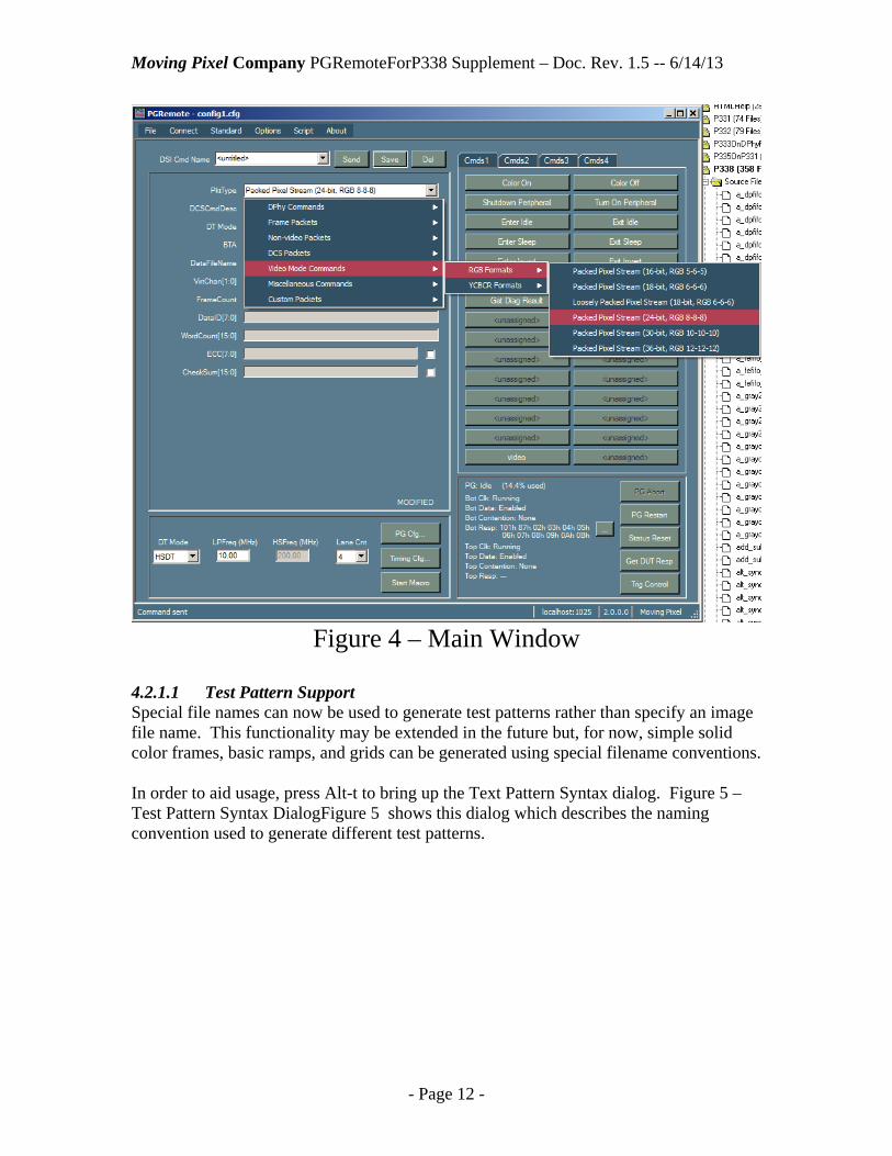
4.2.1.1 Test Pattern Support Special file names can now be used to generate test patterns rather than specify an image file name. This functionality may be extended in the future but, for now, simple solid color frames, basic ramps, and grids can be generated using special filename conventions. In order to aid usage, press Alt-t to bring up the Text Pattern Syntax dialog. Figure 5 – Test Pattern Syntax DialogFigure 5 shows this dialog which describes the naming convention used to generate different test patterns.
Moving Pixel Company PGRemoteForP338 Supplement – Doc. Rev. 1.5 -- 6/14/13
- Page 13 -
Figure 5 – Test Pattern Syntax Dialog A single, solid color frame is generated with the syntax:
SOLID_<R>_<G>_<B>. For example, to generate a full-frame consisting of the single color with red = 100, green = 150, and blue = 200 (8-bit values), enter “solid_100_150_200” as the filename of the video mode or WriteMemory command. A horizontal, vertical, or diagonal ramp can be generated with the syntax:
RAMP_<hvmask>_<rgbmask>. The <hvmask> value, if present, can be 1 (vertical), 2 (horizontal) or 3 (diagonal). The <rgbmask> value, if present, specifies which color planes are active. For example, RAMP_3_4 specifies a diagonal ramp in red-only and RAMP_2_3 specifies a horizontal ramp in both green and blue. A monochrome grid pattern can be generated with the syntax:
GRID_<on_cnt>_<off_cnt>_<solid_line_cnt> _<var_line_cnt> The grid pattern consists of two types of lines: solid lines and variable lines. Variable lines are defined by the user with <on_cnt> and <off_cnt>, basically defining the repeating pattern of “on” pixels followed by “off” pixels. Then the test pattern is formed by a repeating pattern of solid lines for <solid_line_cnt> followed by variable lines for <var_line_cnt>. For example, <on_cnt> = 1 and <off cnt> = 9 defines a variable line that has a single white pixel every 10 pixels. If <solid_line_cnt> = 1 and <var_line_cnt> = 9, then the naming syntax is GRID_1_9_1_9 and the pattern formed is a grid with single line thickness with 10 x 10 squares. GRID_5_15_5_15 defines a grid with 5-pixel line thickness with 20 x 20 squares.

Moving Pixel Company PGRemoteForP338 Supplement – Doc. Rev. 1.5 -- 6/14/13
- Page 14 -
4.2.1.2 Support for Additional Source Image File Formats Now, in addition, to bmp file formats, jpg, png, tiff, and gif files may be used as source image files. With JPEG support, it is easy to use images from video files (AVI, DivX, MPEG, MOV, WMV, MP4, etc) using various third-party extraction tools that are available. One recommended shareware tool is Advanced X Video Converter (http://www.aoamedia.com/videoconverter.htm). This tool is inexpensive and very straightforward to use and image files extracted using this tool adhere to the required naming format for PGRemote images.
4.2.1.3 Image Viewing Dialog An image viewer has been added for the user to view image files used in video and DSI WriteMemory commands. The viewer can be invoked by pressing Alt-i, causing the image file (if present) of the current command to be displayed in a separate image window. Note that this also applies if the filename is the name of a test-pattern, which is a convenient way to see that the pattern name syntax is correct. If the image size is large, it is re-scaled to a reasonable viewing size. Press Return or click OK to close the image window.
4.2.1.4 Automatic Image Scaling Images specified for video and WriteMemory commands are now automatically resized when the command is sent if they do not match the current Timing dimensions. Image resizing is performed using high-quality filtering and interpolation. Previously, an error was thrown if the image size did not match the user-specified timing dimensions.
4.2.1.5 Hierarchical PktType Selection To better organize the many PktType options, the PktType combo-box has been modified to drop down a hierarchical menu. Top-level PktType categories for CSI are:
DPhy Commands Frame Packets Generic Short Packets Non-video Packets Video Mode Commands Miscellaneous Commands Custom Packets
Top-level PktType categories for DSI are:
DPhy Commands Frame Packets Non-video Packets DCS Packets Video Mode Commands Miscellaneous Commands Custom Packets

Moving Pixel Company PGRemoteForP338 Supplement – Doc. Rev. 1.5 -- 6/14/13
- Page 15 -
4.2.1.6 Component Command Naming in Macros When component commands are inserted into macros, if they haven’t been named (i.e. their name is <untitled>) the PktType or DCSPktType is used as the name in the macro. This provides a better self-documenting macros than those with a list of <untitled> commands in them.
4.2.1.7 New Command Button Pages The number of buttons has been increased four-fold, with the addition of four tabbed pages for command buttons. Each page contains 30 command buttons, allowing for expanded command access and command grouping. Simply click on one of the four tab page titles (Cmds1, Cmds2, Cmds3, or Cmds4) to activate the page. New entries into command button context menu (right-click on button) allow for removing assignments to all the command buttons on a page or all buttons on all pages.
4.2.1.8 Command Button Tooltips In addition, command button tooltips can be individually added by the user. Simply, right-click on an assigned command button and select “Set Button Tooltip”. A dialog opens that allows the user to type in tooltip text to associate with the button. The tooltip pops up whenever the mouse is paused over the command button.
4.2.1.9 Expanded Status Display The status display in the lower corner of the main window has been expanded to provide information about the activity of both interfaces. In particular, the following status is provided:
PG State: indicates whether the PG is running or idle. Bot Clk: indicates whether the bottom interface clock is running, stopped, in
ULPS, or is in “Forced LP11” (implying the interface is not active, i.e. in a single-interface mode).
Bot Data: indicates whether the bottom interface data lanes are enabled, in ULPS, or are in “Forced LP11”.
Bot Contention: indicates whether any contention was detected on the bottom interface lane 0.
Bot Resp: indicates the first bytes of DUT response data received on the top interface (retrieved when the PG stops or when the Get DUT Resp button is pressed).
Top Clk: indicates whether the top interface clock is running, stopped, in ULPS, or is in “Forced LP11”
Top Data: indicates whether the top interface data lanes are enabled, in ULPS, or are in “Forced LP11”.
Top Contention: indicates whether any contention was detected on the top interface lane 0.
Top Resp: indicates the first bytes of DUT response data received on the top interface (retrieved when the PG stops or when the Get DUT Resp button is pressed).

Moving Pixel Company PGRemoteForP338 Supplement – Doc. Rev. 1.5 -- 6/14/13
- Page 16 -
4.2.1.10 PG Memory Usage Indication In the status pane, as part of the PG status indication, PG memory usage (in percent) is indicated for the last sent command. One use of this indication is to help determine how many frames can be supported given the current timing configuration (i.e. send a single frame, see how much PG memory is used, then compute the maximum number of frames that will fit).
4.2.1.11 Expanded DUT Response Viewing The following summarizes features and behavior of DUT response acquisition on the P338:
The DUT response buffer on the P338 is 4 Kbytes. When the 4 Kbyte limit is reached during an acquisition, no further data is stored. Multiple read responses can be acquired while looping on a read command, when
sending a macro with multiple read commands, or when multiple reads are inserted during video mode.
Response data is automatically read from the probe and displayed once the PG stops. Thus, response data is not normally available while a command is looping.
However, the “Get DUT Resp” button in the status pane of the main window (or the GET_DUT_RESPONSE or SAVE_DUT_RESPONSE RPC calls) will retrieve and display acquired DUT response data while the PG is running.
To clear the DUT response data from the status display, click on the Status Reset button (this also resets the contention detection state).
For example, if a macro is sent containing 4 read commands, the response data from each will be queued and retrieved after the macro is sent and the PG stops. If the PG loops on the macro, the buffer will fill up with repeated responses, again retrieved only when the PG is stopped (via PGAbort). As with the P331/P332, the first two bytes of each DUT response should always be 01h 87h. The first byte contains only two bits, which represent the escape mode entry sequence. The second byte represents the LPDT escape command itself. As these codes occur whenever a read response is sent by the DUT, they can be used to help parse the response data in the case of multiple reads. PGRemote has been improved to display all acquired bytes of the DUT response for each interface. As in previous versions, only the first 12 bytes of the response are displayed in the status area of the main window. Next to these bytes, there is now a small button with “…”. Clicking this button brings up the DUT Response dialog which shows the entire response in a scrollable textbox. Figure 6 shows an example display of DUT response data. This dialog provides a Save button to save the response data as text to a file. Note that an RPC command is available for automating this process: SAVE_DUT_RESPONSE. It has three arguments: a filename, appendFlag and commentString. The appendFlag determines whether the response is appended to an existing file or a new file is created. An example RPC command might look like:

Moving Pixel Company PGRemoteForP338 Supplement – Doc. Rev. 1.5 -- 6/14/13
- Page 17 -
# SAVE_DUT_RESPONSE “c:\MIPI\responses\DUTResp1.txt” 0 “Response1”
Figure 6 – DUT Response Dialog
4.2.2 PG Configuration Dialog The PG Configuration dialog (see Figure 7) has the following modifications:
The Probe Type combo-box is used to indicate whether the user intends to use a P338 or a P331/P332. This selection is confirmed when PGRemoteForP338 connects to PGAppDotNet and communicates with the PG about what probes are connected.
A second combo-box labeled “P338 Config” is provided for the user to select what operation interface to use. These modes are explained in more detail later, but the selection is among dual-interface modes (half-rate and full-rate), single-interface modes (active top or bottom), and new single-8 interface modes (half-rate and full-rate).
Voltage and delay controls are provided for all lanes from both the top and bottom interfaces.
A new PG Event threshold control is provided to allow the user to set the threshold voltage for input events using the P300 probe (range -2.0 to 2.5 volts). Previously, this value was hard-coded to 1.5 V.
Two new controls (“Bot Link Dly” and “Top Link Dly”) allow user-adjustment of a global delay setting for each interface (requires P338 firmware version 1.9). Normal operation should have these delays at 0, but adjustments of up to 188 HS

Moving Pixel Company PGRemoteForP338 Supplement – Doc. Rev. 1.5 -- 6/14/13
- Page 18 -
byte clocks (converted to ns) are supported for each interface. The value is quantized to byte clock increments and thus the exact available settings and range are dependent on the HS clock frequency.
Using the “Insert Cmd Link(s)” control, the user can specify which interfaces receive an inserted command (during video or via a CMD_INSERTION_POINT command in a macro). Options are “Bottom”, “Top”, or “Both”.
Figure 7 – PG Configuration Dialog
Moving Pixel Company PGRemoteForP338 Supplement – Doc. Rev. 1.5 -- 6/14/13
- Page 19 -
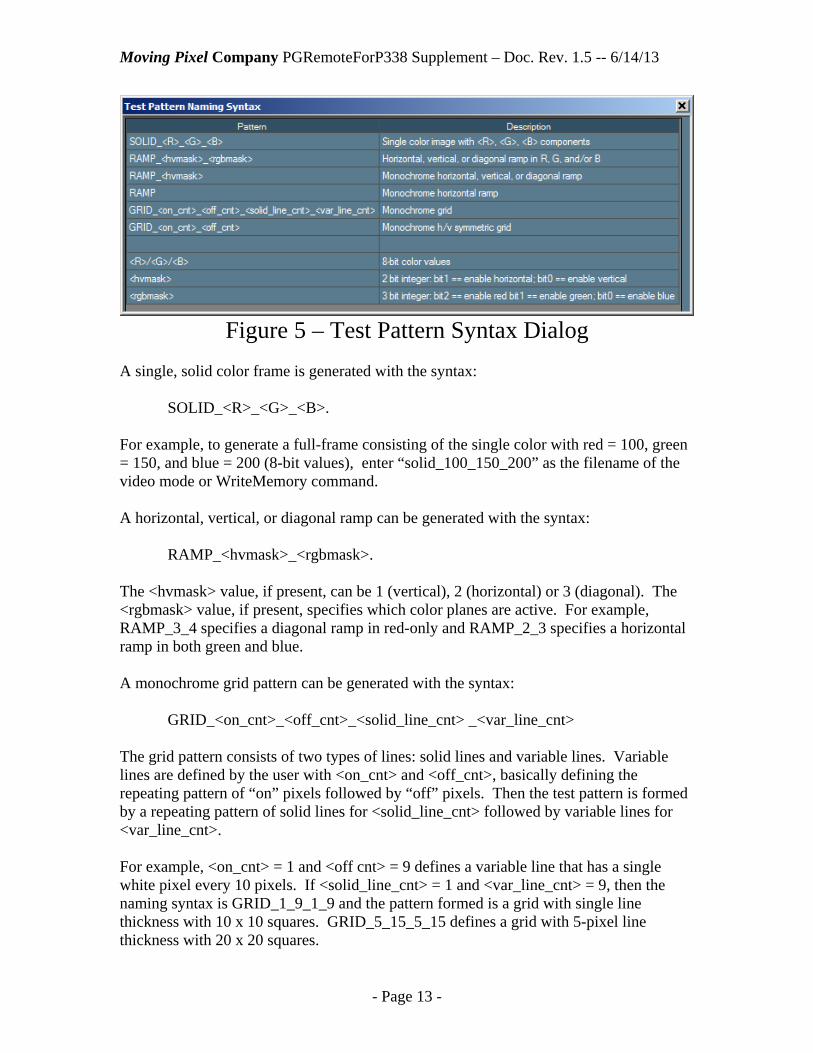
4.2.3 Timing Dialog The Timing dialog has a few modifications (see Figure 8):
A new combo-box control labeled “Dual-Interface Mode” is provided. The control is enabled only when a dual-interface mode has been selected in the PG Configuration dialog. When active, the control indicates how the user wants to transmit video frames with respect to each interface (including video data sent via DSI WriteMemory commands). These modes are discussed further later in this document, but there are four modes: clone image, dual image, even/odd pixel, and left/right image.
Figure 8 – Frame Timing Dialog

Moving Pixel Company PGRemoteForP338 Supplement – Doc. Rev. 1.5 -- 6/14/13
- Page 20 -
Two additional buttons are provided labeled “x2” and “/2” (next “Horizontal Scale”). These buttons are to make switching between the dual-interface modes easier, scaling all horizontal image dimensions (HSync, HBPorch, HFPorch, HActive, and HTotal) by 2 or ½ respectively. See later discussion.
A new checkbox “Allow Blanking Adjustment” allows the application to adjust blanking segments slightly to avoid most alignment errors that might occur when building the frame. These errors are specific to requirements of the PG not the MIPI standards. This checkbox is enabled when the standard is set to DSI and “Enable New Video Mode” is checked.
A new checkbox “Overlap (pix)” and an associated textbox are enabled when in the “Left/Right Image”, dual-interface mode, when the standard is set to DSI, and “Enable New Video Mode” is selected. When checked, the overlap setting causes additional duplicated pixels to be output each interface. On the bottom interface which sends the left half of the image, the first X pixels of the right-half image are sent at the end of the active line. On the top interface, which sends the right half of the image, the last X pixels of the left-half image are sent at the beginning of the active line (where X is the overlap setting).
A new checkbox “Enable Video Decimation/Expansion” and a button to bring up the Video Decimation/Expansion dialog is provided. Please see the next section for a description of this dialog and mode of operation.
4.2.4 Video Decimation/Expansion Dialog This dialog (shown in Figure 9) is brought up via a button in the Frame Timing dialog when video decimation/expansion is enabled. It configures the parameters for video decimation in PGRemoteForP338, allowing real-time expansion of video frames during CSI and DSI video modes in the P338 probe.

Moving Pixel Company PGRemoteForP338 Supplement – Doc. Rev. 1.5 -- 6/14/13
- Page 21 -
Figure 9 – Video Decimation/Expansion Dialog This capability allows significant savings in PG memory usage and download time for large video images and/or long video sequences. As a result, when using this mode, the maximum frame size and/or maximum video sequence length is greatly increased. Of course, image quality is correspondingly reduced, but often image quality is not the overriding concern when testing devices. One additional advantage when using this mode is that pixel data is packed more efficiently in PG memory. This makes memory usage for active pixel data independent of the number of lanes. As a result, for example, a single lane image can pack six times as much pixel data into the same amount of PG memory! Even using 4 lanes, the efficiency is still 1.5 times normal.
4.2.4.1 Algorithm Description Video decimation is the use of fewer source pixels than pixels in the final MIPI video frame output. Source pixels are duplicated in the probe by factors determined by the settings in this dialog. These are the steps taken to build the PG program for video mode when video decimation/expansion mode is enabled:
Moving Pixel Company PGRemoteForP338 Supplement – Doc. Rev. 1.5 -- 6/14/13
- Page 22 -
1. Image file is imported into source image buffer. 2. Source image is resized, if requested, according to settings. 3. Source image data is used to build video mode program. 4. If source image is larger than the image data needed, only upper-left corner of
image is used as necessary. Then, when the PG is running, the P338 probe expands incoming video data, replicating each pixel by DupX and each line by DupY to create the final output image(s). There are two major aspects to video decimation: the size of the source image and the duplication factors in horizontal and vertical dimensions. In this discussion, the source image may not necessarily have the same dimensions as the input image (i.e. the dimensions of the image in the input file), depending on whether it is rescaled or not on input.
4.2.4.2 Specifying the Source Image Size: To specify the source image size to use, there are three options:
1. Check “Inherit from image file” and leave “Rescale input image” unchecked. In this case, the source image size will be the same as the input image size.
2. Check “Inherit from image file” and check “Rescale input image”. In this case, the input image will be resized to SrcX by SrcY pixels on input.
3. Check “Compute from duplication factors (and dst image size). In this case, the output frame timing settings (HActive and VActive) and the duplication factors (DupX and DupY) will determine the source frame size. In particular, the source image size will be (HActive / DupX) by (VActive / DupY).
4.2.4.3 Specifying the Duplication Factors: To specify the duplication factors in horizontal (X) and vertical (Y) directions, there are two options:
1. Check “Auto-compute duplication factors” (available if “Inherit from image file” is checked). If this option is checked, then the duplication factors will be determined from the source and output image sizes. That is:
DupX = HActive / source_image_width DupY = VActive / source_image_height.
2. Enter integer factors into DupX and DupY text boxes. There are some restrictions on DupX and DupY, depending on the pixel format and video mode. Minimally, DupX must be even, though it must be multiple of 4 if a dual-image mode is used. DupY is only restricted in CSI RAW modes, where it must then be even. Note that when the source_image_width and source_image_height do not divide evenly into the output image, the remainder edges are padded with black.
4.2.4.4 Supported Video Formats The pixel formats that are supported by video decimation are:

Moving Pixel Company PGRemoteForP338 Supplement – Doc. Rev. 1.5 -- 6/14/13
- Page 23 -
Any 16-bit RGB formats for CSI/DSI Any 24-bit RGB formats for CSI/DSI RAW8 and RAW10 Bayer formats for CSI
Also, while DSI video mode normally can support timing configurations where pairs of lines end on a byte boundary, video decimation requires that single lines end on a byte boundary.
4.2.4.5 Raw Mode Behavior: The RAW formats require additional processing to ensure color-plane coherency when pixels and lines are replicated. Because the color planes are sub-sampled, single pixels or single lines cannot be replicated. Instead pixel-pairs and line-pairs must be replicated to maintain color coherency. For this process to be successful, the two green pixels in each pixel-quad must be made the same. Thus, the source image is processed to replace each green pixel with the average of it and its quad companion green pixel. One other processing note is that in the RAW10 format, the 2 lsbs of each pixel are set to zero. This has the advantage of another 20% compression savings for active pixel data, but this is mainly for implementation reasons.
4.2.4.6 Examples: Consider a 1280 x 720 display and a 320 x 240 input image file using a single-image mode and the RGB888 format. Example 1: “Inherit from image file” is checked and DupX = 4 and DupY = 5.
In this case, the input image is not resized and each pixel of each source line is replicated 4 times to fill an output line. Only 144 lines of the input image are used, each replicated 5 times to fill the output image.
Example 2: “Inherit from image file” and “Auto-compute duplication factors” are
both checked. In this case, DupX and DupY will be computed to be 4 and 3 respectively. The input image is not resized and, because the source image dimensions divide evenly into the output image dimensions, all of the source image is used.
Example 3: “Compute from duplication factors (and dst image size)” and
“Rescale input image” is checked and DupX = 2 and DupY = 2. In this case, the input image is resized to 640 x 360. Then each source image pixel and each source line is replicated twice, using all of the source image data. Note that if “Rescale input image” was not checked, an error would be thrown because the source image does not have enough data.
4.2.5 Trigger Control Dialog The new Trigger Control dialog (see Figure 10) can be opened by clicking the “Trig Control” button in the bottom-right of the main GUI window.

Moving Pixel Company PGRemoteForP338 Supplement – Doc. Rev. 1.5 -- 6/14/13
- Page 24 -
Figure 10 – Trigger Control Dialog
This dialog allows configuration for the auto-frame advance feature of the P338 probe, setting the trigger pulse width, and sending an immediate trigger pulse. These functions are described below. Note that for connectivity convenience, the TrigOut signal is duplicated and send out the GPO0 pins on the rear-connector. In particular, the GPO0 signal allows direct connection to the P300 Inputs probe of the P300 using the flying-leadset provided. This signal can then be used as the external event signal for triggering the sending of commands and/or advancing frames in video mode.
4.2.5.1 Configuring for Auto-Frame Advance The auto-frame advance feature of the P338 allows the TrigOut to control frame advance during video mode. In this case, the period of TrigOut pulses is set by the Frame Advance Cnt setting. So, for example, a Frame Advance Cnt of 10 causes each frame in the video sequence to be replicated 10 times. Effectively, this setting is a speed control for video sequence playback To use the auto-frame advance feature, do the following:
1. Connect the GPO0 or TrigOut signal to the Event0 input of the P300 Inputs probe to the PG (see Figure 3 for the location of GPO0 on the rear panel of the P338). (note that the black wire is the active wire in the twisted pair for Event0 on the P300 leadset).
2. Check “Enable auto-frame advance using probe trigger”. When this option is checked, the option “Run PG on external event” is implicitly assumed to be true during the sending of video (i.e. the user does not need to set this option manually). In addition, the initial event to start video playback is automatically sent to the PG when the video command is sent.
3. Set “Frame Advance Cnt” to the desired frame period 4. Send the video mode command of choice in continuous mode using a
FrameCount greater than one.

Moving Pixel Company PGRemoteForP338 Supplement – Doc. Rev. 1.5 -- 6/14/13
- Page 25 -
Once video is running, the video sequence will play and loop at the speed setting set by Frame Advance Cnt. Note that this setting can be adjusted in real-time while video is playing to change the apparent rate of video playback. Note this feature can be used with any video-mode format in both CSI and DSI. One restriction to this mode is that the maximum frame count in the video sequence is 63 frames.
4.2.5.2 Configuring for Manual-Frame Advance Another way to use the TrigOut signal to control video playback is by manually clicking on the Trig button. In this case, step (1) above should still be performed, connecting GPO0 or TrigOut to the Event0 input. However, “Enable auto-frame advance using probe trigger” should be unchecked and the option “Run PG on external event” should be checked in the Options menu. Then, once video is sent, click the Trig button to initially play and loop on the first frame. Subsequent clicks on the Trig button will cause a manual advance to the next frame in the video sequence.
4.2.5.3 Sending Trigger Pulses Independent of frame-advance modes, a trigger pulse can be sent by clicking on the Trig button. This can occur at any time the application is connected to a PG connect to a P338 probe (i.e. whether the PG is running or not). The pulse width can be set by setting the Trig Pulse Duration (max 80 ms). In addition, the TrigOut signal can be controlled during playback via the “Assert Probe Trig” command (in the Miscellaneous Commands PktType group). This command has a single integer Trig Cmd argument representing how the Trigger signal should be set. Select from the following argument settings: TRIG_CMD_LOW 0 Sets TrigOut and GPO0 to a low voltage TRIG_CMD_HIGH 1 Sets TrigOut and GPO0 to a high voltage TRIG_CMD_TOGGLE 2 Toggles the current state of TrigOut and GPO0. TRIG_CMD_PULSE 3 Pulses TrigOut and GPO0 for the duration specified in
Trig PulseDuration. Note that pulses can have either polarity (high-low-high or low-high-low), depending on the current state of the TrigOut signal when the command is sent.
Most useful is to embed these commands in a macro to control TrigOut timing during the macro.
4.2.5.4 Troubleshooting Frame Advance Modes If video data does not appear on the MIPI link(s) when sending a video command in one of the Frame Advance modes, it is likely that the PG is waiting on the initial event to start playing. This will be indicated in the status window with the first line reading: “PG: Waiting on Evt 1”1 In this case, check the connection of the P300 Inputs probe and its
1 Evt 1 is the name that the PG gives the event pattern used by the program. In the PG, Evt 1 is defined as a rising edge on the Event0 line.

Moving Pixel Company PGRemoteForP338 Supplement – Doc. Rev. 1.5 -- 6/14/13
- Page 26 -
connection to the Event0 signal. Also, check that the event threshold is set appropriately in the PG Configuration dialog (it defaults to 1.5 V).
4.2.6 GUI Options Dialog The GUI Options dialog is brought up via the “Set GUI Options” item in the Options menu (see Figure 11). The dialog provides the user with options to suppress warnings displayed by the application. In particular, the user can suppress warnings about discarding the current macro or command, when the PG is to be stopped to reconfigure or send a new command, and when the LP frequency is quantized to a different value when the HS frequency is changed.
Figure 11 – GUI Options Dialog
4.2.7 Firmware Update Dialog Unlike its predecessors (P331/P332), the firmware of the P338 can be updated in the field. This is done using the “Update P338 Firmware…” option of the Connect menu. The first step to updating the P338 firmware is to connect a USB cable from your computer to the USB port of the P338. This connection is only necessary during firmware update and is not needed during normal operation. Once the USB cable is connected and the P338 is powered on, selecting the “Update P338 Firmware…” option brings up a connection dialog as shown in Figure 12.

Moving Pixel Company PGRemoteForP338 Supplement – Doc. Rev. 1.5 -- 6/14/13
- Page 27 -
Figure 12 – USB Connection Dialog The connection dialog is a generic dialog for connecting to several Moving Pixel Company instruments, including the PG, DPhy Preprocessor, and the P338 probe. Ensure the Device Type selected is “P338 Probe” and select the serial number of the probe to update. If desired, click the Scan button to update the Serial # list with devices that were connected/powered on since the dialog was opened. When the P338 device to update is selected, click on the OK button. Next the Firmware Update dialog is displayed as shown in Figure 13. Some functions of this dialog are for Moving Pixel Company use only and are protected by a password. The only controls the user generally needs to be concerned with are the Firmware Filename and the Program button. Click on the Browse button associated with the firmware filename to select the .rbx firmware filename that you received from The Moving Pixel Company. Then press the Program button to start programming. Programming takes about 3 minutes during which the status bar will update the progress. When programming is complete, click on the Close button. The new firmware will not take effect until the power of the P338 is cycled. This can be done without shutting down PGRemoteForP338 or PGAppDotNet as long as, after power-cycling, you reconnect to PGAppDotNet using the Connect->PG Connect menu option. This reconnects to and reinitializes the P338.
Figure 13 – Firmware Update Dialog

Moving Pixel Company PGRemoteForP338 Supplement – Doc. Rev. 1.5 -- 6/14/13
- Page 28 -
4.2.8 Color Dialog The color options dialog allows the user to adjust colors for use in the application. This dialog is experimental and some colors are not very useful to change. However, changing the Button background and the Form background can have pleasing effects. To bring up the Color Options Dialog, select “Set Colors…” in the Options menu. To change a color, first select the color type option, for example in Figure 14, the “Form BG” (form background) is selected. Then left-click and drag in the color square, adjust the color sliders, or type in color values to set the color. The color rectangles to the left of the option buttons show the currently assigned color. Clicking on a rectangle makes the selected color the current color, i.e. fills in the color settings. This way, control colors can easily be copied to other controls. As colors are selected, the main window colors change to reflect the new settings. When finished, click OK to keep the new colors, Cancel to discard the new colors, or Defaults to restore the colors to the application defaults.
Figure 14 – Color Dialog
4.2.9 Enhanced Command Insertion Command insertion has been enhanced in PGRemoteForP338:
1. Commands with their BTA field set can now be inserted. 2. Commands can be directed to be inserted on top, bottom, or both interfaces
simultaneously using the “Insert Cmd Link(s)” control in the PG Configuration dialog.

Moving Pixel Company PGRemoteForP338 Supplement – Doc. Rev. 1.5 -- 6/14/13
- Page 29 -
3. Insertion behavior can be set by the user with the “Discard data during cmd insertion” menu option.
When a command with its BTA field is inserted into both links, the probe will give up the bus and wait on both interfaces after sending. If the BTA timeout occurs before either link has seen a return BTA sequence, both links abort and both links continue as if a response had been seen. Otherwise, if a response is seen on a link, the state of the alternate link is checked. If it did not receive a BTA acknowledge sequence, then the alternate link aborts and both links continue. Finally, if the alternate link did receive a proper BTA acknowledge sequence, both links continue to wait until the alternate link receives a return BTA sequence or the BTA timeout occurs. The “Discard data during cmd insertion” gives the user more control over the behavior of the probe during command insertion. Prior to PGRemoteForP338 version 3.0, commands that are inserted into the output stream actually overwrite existing LP11 data in the stream. Thus, during video, sync timing is preserved, assuming the insertion finishes before the next sync packet (which is enforced). If “Discard data during cmd insertion” is set, this behavior is preserved. However, if this option is not set, the command is truly inserted into the stream, delaying the program until the command has been inserted. During video, this would delay the subsequent HSync Start (DSI) or Line Start (CSI), lengthening the vertical blanking line. For commands with their BTA field set, this behavior also applies to the BTA waiting time while the DUT owns the bus. Note that if “Discard data during cmd insertion” is set and the DUT response time is longer than a vertical blanking line, this can cause errors in the video stream (i.e. a corrupted or non-existent HSync Start or HS blanking packet).
4.2.10 Menus The menus in PGRemoteForP338 are mostly unchanged from PGRemote. Items in the Options menu have been reordered somewhat. Also, new menu selections have been added:
Options->Set Colors… -- brings up the Color Dialog Options->GUI Options… -- brings upt the GUI Options dialog Connect->Update P338 Firmware… -- brings up the Firmware dialog Options->Discard Data During Command Insertion – new option to set the
behavior of the instrument during command insertion. About->Help P338 Supplement… -- brings up this document in Help form About->Help RPC… -- brings up the PGRemoteRPC document in Help form,
now separate from the PGRemote Users Guide.

Moving Pixel Company PGRemoteForP338 Supplement – Doc. Rev. 1.5 -- 6/14/13
- Page 30 -
Two options are disabled for the P338: “Use external clock as 10 MHz reference clock on P331/P332” and “Configure For Dual-Synchronized Video” as the probe does not support these functions.
4.2.11 RPC Several extensions to RPC have been implemented for PGRemoteForP338. This section describes new commands and commands that have been modified. The PGRemoteUsersManual also provides additional details.
4.2.11.1 New RPC Commands
4.2.11.1.1 SET_P338_CONFIG This command sets the operating configuration of the P338, which is configured in the GUI in the PG Configuration dialog. Its single argument is one of the following:
- FULL_RATE_DUAL_INTERFACE = 0 - HALF_RATE_DUAL_INTERFACE = 1 - FULL_RATE_BOTTOM_INTERFACE = 2 - FULL_RATE_TOP_INTERFACE = 3 - FULL_RATE_SINGLE8_INTERFACE = 4 - HALF_RATE_SINGL8_INTERFACE = 5
4.2.11.1.2 SET_PROBE_TYPE This command sets the probe type, which is also configured in the GUI in the PG Configuration dialog. Its single argument is one of the following:
- PT_P331 = 15 - PT_P332 = 17 (same effect as PT_P331) - PT_P338 = 18
4.2.11.1.3 SET_TIMING_DUAL_INTERFACE_MODE This command sets the dual-interface mode, which is configured in the GUI in the Timing Configuration dialog. Its single argument is one of the following:
- DI_CLONE_INTERFACE = 0 - DI_DUAL_IMAGE = 1 - DI_LEFT_RIGHT_IMAGE = 2 - DI_EVEN_ODD_PIXEL = 3
4.2.11.1.4 ASSERT_PROBE_TRIG This command sets the state of the TrigOut (and GPO0) signal of the P338 when it is sent as a MIPI command (i.e. use as the PktType for SEND_MIPI_CMD). It can be embedded in a macro to synchronize TrigOut signaling to MIPI traffic. Its single argument is one of the following:
- TRIG_CMD_LOW = 0 - TRIG_CMD_HIGH = 1 - TRIG_CMD_TOGGLE = 2 - TRIG_CMD_PULSE = 3

Moving Pixel Company PGRemoteForP338 Supplement – Doc. Rev. 1.5 -- 6/14/13
- Page 31 -
4.2.11.1.5 FORCE_PROBE_TRIG This command sets the state of the TrigOut signal of the P338 immediately, regardless of whether the PG is running or not (e.g. it can be sent during continuous video modes or looping commands). It uses the same arguments definition as ASSERT_PROBE_TRIG.
4.2.11.1.6 SET_PROBE_TRIG_DURATION This command sets the duration of the trigger pulse when ASSERT_PROBE_TRIG or FORCE_PROBE_TRIG is sent with the TRIG_CMD_PULSE argument. The single argument is sent as a floating point value in seconds, where 80 ms is the maximum duration.
4.2.11.1.7 ENABLE_AUTO_FRAME_ADVANCE This command enables or disables auto-frame advance mode using the TrigOut signal. Its integer argument should be 0 (disable) or 1 (enable).
4.2.11.1.8 SET_AUTO_FRAME_ADVANCE_COUNT This command sets the frame period between TrigOut pulses when auto-frame advance mode is enabled.
4.2.11.1.9 SET_LINK_DELAY This command sets the global link delay associated with the top or bottom interface. It takes two arguments: the first is an integer argument for the interface to set the delay (0 == bottom, 1 == top) and the second is a floating point argument representing the delay in seconds.
4.2.11.1.10 SET_DUAL_LINK_INSERT_IFACE This command sets the interface(s) that are used for command insertion (during video or at a CMD_INSERTION_POINT in a macro). The single integer argument indicates the interface: (0 == bottom, 1 == top, 2 == both).
4.2.11.1.11 LOAD_CONFIG This command loads a previously saved configuration file. Its single string argument is the configuration file name. Example: # LOAD_CONFIG “TestConfig.cfg”
4.2.11.1.12 SAVE_CONFIG This command saves the current command and button configuration to a file. Its single string argument is the configuration file name. Example: # SAVE_CONFIG “TestConfig.cfg”
4.2.11.1.13 ASSIGN_BUTTON This command assigns a command and tooltip text to a button. It requires four arguments. The first two are integers and represent the button page number (0-3) and the button number on the page (0-29) to use for the assignment. The second two arguments are strings, with representing the command name to assign to the button and the tooltip text to associate with the button respectively.

Moving Pixel Company PGRemoteForP338 Supplement – Doc. Rev. 1.5 -- 6/14/13
- Page 32 -
Use an empty string (“”) for the command argument to unassign the button. The value of -1 can be used with the integer arguments to indicate all pages, or all buttons on a page (useful for group unassignment). Example: # ASSIGN_BUTTON 1 2 “TestCmd” “This is the tooltip for TestCmd”
4.2.11.1.14 ADD_MIPI_CMD This command allows a command to be defined as a named command in the GUI. It has the same arguments as the SEND_MIPI_CMD with one additional argument preceding all other command arguments. This is a string argument containing the name of the command to define. Note that any existing command with the same name is automatically deleted first. Note that when used within a macro definition, ADD_MIPI_CMD provides a way to name the component command being compiled into the macro (see ADD_MACRO below). Example: # ADD_MIPI_CMD “TestCmd” LP_DELAY 0 0 DT_LP 0 100 1 2 “” NULL
4.2.11.1.15 ADD_MACRO This command allows a macro to be defined as a named command in the GUI. It is used as the last command in a macro definition instead of the SEND_MACRO command. Its single argument is the name of the macro to define. Note that any existing command with the same name is automatically deleted first. Example: # START_MACRO # ADD_MIPI_CMD “Cmd1” … # ADD_MIPI_CMD “Cmd2” … … # ADD_MACRO “TestMacro”
4.2.11.1.16 DELETE_CMD This command deletes a named command in the GUI. Its single argument is the name of the command to delete. Example: # DELETE_CMD “TestCmd”
4.2.11.1.17 DELETE_ALL_CMDS This command deletes all named commands in the GUI. It has no arguments. Example: # DELETE_ALL_CMDS

Moving Pixel Company PGRemoteForP338 Supplement – Doc. Rev. 1.5 -- 6/14/13
- Page 33 -
4.2.11.1.18 WRITE_CURRENT_STATE This command writes the current state as RPC commands to the given script filename. It the file already exists, it is overwritten. Its single argument is the name of the script file to write the current state. Example: # WRITE_CURRENT_STATE “c:/mipi/currentstate.txt”
4.2.11.2 Enhanced RPC Commands The following RPC commands now have an optional single integer argument which indicates the interface to apply the command to.
GET_LP_CONTENTION RESET_LP_CONTENTION GET_DUT_RESPONSE
Use either 0 for the bottom interface or 1 for the top interface. If the argument is not present, 0 is assumed. Similarly, the SAVE_DUT_RESPONSE command has an optional fourth integer argument, which indicates the interface to apply the command to. Use either 0 for the bottom interface or 1 for the top interface. If the argument is not present, 0 is assumed. Finally, the IS_LANE_CLK_RUNNING command semantics should be treated as returning whether the active interface(s) have their lane clock running or not. In any dual-interface mode, both interface clocks will be in the same state.
4.3 PGRemoteForP338 Operation This section describes how PGRemoteForP338 operation and corresponding P338 behavior.
4.3.1 Setting the P338 Operating Configuration When using PGRemoteForP338 for the first time, the first new step that should be taken is to set the P338 Operating configuration. The P338 has six operating configurations:
Full-rate, Dual-interface – both output MIPI links are active and can output at bit rates up to 1.6 Gbps per lane. All commands are sent out with identical timing, on both interfaces. This includes all parameters that affect MIPI packets such as LaneCnt, DTMode, LPFreq, HSFreq, DPhy timing, frame timing, and any option settings. This configuration requires two merged PG modules.
Half-rate, Dual-interface – similar to the full-rate, dual-interface configuration except that only one PG is used and the maximum bit rate is 800 Mbps per lane.
Full-rate, Bottom-interface – only the bottom MIPI link is active and can output at bit rates up to 1.6 Gbps per lane. Essentially, the P338 in this configuration acts

Moving Pixel Company PGRemoteForP338 Supplement – Doc. Rev. 1.5 -- 6/14/13
- Page 34 -
like a P332 probe connected to the bottom interface. Note that only one PG is required but this configuration will also work if two PGs are connected.
Full-rate, Top-interface -- only the top interface is active and can output at bit rates up to 1.6 Gbps per lane. Essentially, the P338 in this configuration acts like a P332 probe connected to the top interface. Note that only one PG is required but this configuration will also work if two PGs are connected.
Full-rate, Single-8 Interface – both output MIPI links are active but operate as a single, (up to) 8-lane, 1.6 Gbps per lane interface. In this mode, the lane count setting can range from 1-8, where lanes 0-3 are output on the bottom link and lanes 4-7 are output on the top link (note that lane mapping is not supported in this mode). This configuration requires two-merged PG modules.
Half-rate, Single-8 Interface -- similar to the full-rate, single-8 interface configuration except that only one PG is used and the maximum bit rate is 800 Mbps per lane.
In either of the dual-interface configurations, video-mode packets and DSI WriteMemory commands may different image data between interfaces depending on the Dual-Interface Mode setting (Timing Configuration dialog). These modes are described further in the next section. To set the operating configuration in the GUI, go to the PG Configuration dialog (PG Cfg… button in the main window), set the Probe Type to P338 and select the desired configuration in the P338 Config combo-box. Once the OK button is clicked in the dialog, the probe is reconfigured according to all the configuration settings. In particular, one of the steps taken when changing the operating configuration of the P338 is shutting down the clocks on both interfaces if they are active. Thus, after reconfiguration, all lanes of both links will be in LP11. Only once an initial command is sent, will the clock lane(s) re-enter HS mode (depending on the command and according to the same rules as for the P331/P332).
4.3.2 Setting the Dual-Interface Mode for Video When sending video, either through video mode commands or DSI WriteMemory commands, the dual-interface mode setting determines how video image data is mapped to the active interfaces.2 There are four dual-interface modes:
Clone Image – Frame Timing parameters describe the video frame format for one interface. Identical image data is sent out each interface.
Dual Image – Frame Timing parameters describe the video frame format for one interface. A special filename convention is used to import two image files, where
2 Normally, Frame Timing parameters are not applicable to WriteMemory commands, but an exception is made here. The dual-interface mode setting is the used for WriteMemory commands in addition to video mode commands.

Moving Pixel Company PGRemoteForP338 Supplement – Doc. Rev. 1.5 -- 6/14/13
- Page 35 -
one image file is output on the top interface and one image is output on the bottom interface.
Left/Right Image – Frame Timing parameters describe a combined video frame format for both interfaces. The bottom interface sends the left half of the image data and the top interface sends the right half of the image data.
Even/Odd Pixel -- Frame Timing parameters describe a combined video frame format for both interfaces. The bottom interface sends even pixels of the image data and the top interface sends odd pixels of the image data. The first pixel of each line is considered to be an even pixel (pixel 0).
As a point of terminology, the Left/Right Image and Even/Odd Pixel modes are named “split-image” modes to distinguish them from Clone Image and Dual Image modes. To configure the dual-interface mode, open the Timing Configuration dialog (Timing Cfg.. button in the main window) and select the desired option in the Dual-Interface Mode ComboBox at the bottom of the dialog. Note that this control will not be enabled unless the P338 configuration mode is set to one of the dual-interface modes (see previous section).
4.3.3 Setting Video Timing Parameters Specifying the horizontal blanking for images in the Timing Configuration dialog depends on the P338 operating configuration and dual-image mode. In non-split-image modes (i.e. not Left/Right Image or Even/Odd Pixel), horizontal timing should specify the display or camera timing, exactly as with P331/P332 operation. On the other hand, in split-image modes, horizontal timing should refer to the timing for a single DUT display or camera, which will have all of its blanking settings as 2x what each interface sees. Another way of saying it is that horizontal blanking settings are divided by 2 to determine the timing for each interface. As a result, all horizontal timing settings must be even. To aid the user in switching between split-image and non-split-image modes, two buttons are provided in the Timing Configuration dialog (labeled x2 and /2) that scale the horizontal timings as indicated. Note that if “Overlap” is enabled in “Left/Right Image”, dual-interface mode using the DSI standard, each interface will have an additional number of pixels appended/prepended to lines based on the Overlap setting. For example, if HActive is set to 1200 and Overlap is enabled and set to 4, each interface will have an active line of 604 pixels.
4.3.4 WriteMemory Configuration The DSI WriteMemoryStart and WriteMemoryContinue commands support dual-interface video modes. Thus, be aware that the dual-interface mode setting in the Timing Configuration is relevant to WriteMemory commands. The WriteLen parameter in split-image modes must specify the combined number of data bytes to be written to both interfaces. A restriction in this case is that the WriteLen

Moving Pixel Company PGRemoteForP338 Supplement – Doc. Rev. 1.5 -- 6/14/13
- Page 36 -
parameter used by the application must be a multiple of the video line length. This is so partitions can be made an integral number of lines and then split according to the mode. To do this, the partition length given by the user in the WriteMemory Configuration dialog will be quantized (rounded) to a multiple of the line length. One complexity for PGRemote in sending a WriteMemory command is that the source data file can optionally be a binary data file (instead of a BMP file). In a dual-interface mode, a WriteMemory command is assumed to be sending image data and a binary data file has no corresponding line length information for parsing the file. Thus, the user must provide this information for correct partitioning of data between interfaces. In the WriteMemory Configuration dialog (Options->Configure WriteMemory… menu) there is a new control labeled “Binary Image File Line Length”. This specifies the number of pixels in a line of the binary file.. As with video mode horizontal timing, in split-image modes, the Binary Image File Line Length setting should represent the line width of the aggregate display. Note that the BMP Decode format is used to determine the pixel size of the binary input file.
4.3.5 Specifying Image Filenames Video-mode commands and WriteMemory commands are given an image filename as a parameter to the command. For video-mode commands, there already exists a special naming convention to allow for multiple frames in a sequence to be output. This naming convention has been extended for video-mode and defined for WriteMemory commands to support dual-interface, dual-image mode. Specifically, filenames used in dual-image mode require that the file names, not including extension, end in “A” or “B” (e.g. “ImageA.bmp” and “ImageB.bmp”). The “A” filename is specified in the command and the “B” filename is implicitly used. The “A” image is sent out the bottom interface and the “B” image is sent out the top interface. For video-mode sequences, the protocol already exists to use an incrementing number at the end of files (e.g. “Image1.bmp”, “Image2.bmp”, “Image3.bmp”). For the dual-interface, dual-image mode, filenames should have “A” or “B” following the incrementing number (e.g. “Image1A.bmp”, “Image1B.bmp”, “Image2A.bmp”, “Image2B.bmp”, etc.). Finally, to allow for compatibility with non dual-image modes, the “A” and “B” dual-image sequences can still be used in these modes. For example, sending the following command when in the single-interface mode using the top interface only (i.e. P338 Config = “FULL-RATE TOP”): PktType = “Packed Pixel Stream (24-bit RGB 888) DataFileName = “Image1A.bmp” FrameCount = 3

Moving Pixel Company PGRemoteForP338 Supplement – Doc. Rev. 1.5 -- 6/14/13
- Page 37 -
the images sent out the top interface would be “Image1A.bmp”, “Image2A.bmp” and “Image3A.bmp”. Similarly, if the DataFileName were set to “Image1B.bmp”, the images sent out the top interface would be be “Image1B.bmp”, “Image2B.bmp” and “Image3B.bmp”. Note that, as described in section 4.2.1.1, filenames can also specify a test pattern rather than a file. If a test pattern is used in dual-image mode, the same image will be sent to each interface.
4.3.6 Sending Non-video Commands When operating in single-interface configurations, sending a non-video command or macro with the P338 behaves exactly as with the P331/P332. The command will be sent out the top or bottom interface according to the current configuration as the alternate interface is held in LP11. When operating in dual-interface configurations, sending a non-video command causes the command to be sent out both interfaces simultaneously. For read commands (or any command with BTA true), the following behavior is observed:
Both interfaces tri-state and acquire response data until a return BTA is observed. Each interface independently acknowledges a return BTA on its link then holds its
link in LP11 until the other link is ready to continue. If a link has not received a return BTA before the BTA timeout expires, it aborts
the read, driving LP11 on the link. Then both links continue with the MIPI program.
If a link has not received any bits before the other link has completed its read, it aborts its read and drives LP11 on the link. Then both links continue with the MIPI program.
In summary, read commands and BTA sequences go out both links in dual-interface mode. If both links respond, the data from each link is acquired. If only one link responds, the data is acquired from that link and the alternate link aborts. If neither link receives a response before the BTA timeout, both links abort. Please see section 4.2.1.10 for further details about DUT read response behavior.
4.3.7 Command Insertion The P338 supports command insertion during video mode similar to the P331/P332 probes. However, a few enhancements have been made:
1. When running in a dual-interface mode, the user can select which interface(s) (top, bottom, or both) to use for command insertion. This is achieved using a control labeled “Insert Cmd Link(s)” in the PG Configuration Dialog (enabled only when a dual-interface mode is enabled). Note that this setting also applies when using a “Cmd Insertion Point” in a macro.
Moving Pixel Company PGRemoteForP338 Supplement – Doc. Rev. 1.5 -- 6/14/13
- Page 38 -
2. The user can now insert read commands during video (or when using a “Cmd Insertion Point”). Note that video timing is suspended for the time that the DUT owns the bus. Thus, the video line time of the vertical blanking line containing the inserted command is extended.
As described previously in section 4.2.1.11, each interface captures and aggregates response data from the DUT following read commands. During looping video (or other command), acquired data is not immediately visible to the user until the command exits. To view response data while a command is still running, use the “Get DUT Resp” button in the status pane of the main window. This button will become enabled if there is any response data to be uploaded from the probe.