Embed Size (px)
Citation preview

LCD PROJECTOR
MODEL
PG-A20X
OPERATION MANUAL
Intro
du
ction
Co
nn
ection
s and
Setu
pB
asic Op
eration
Easy to
Use F
un
ction
sA
pp
end
ix
PG-A20X_E_PDF_Hyo1.p65 03.4.23, 9:53 AM1
IMPORTANTFor your assistance in reporting the loss or theft of yourProjector, please record the Serial Number located onthe bottom of the projector and retain this information.Before recycling the packaging, please be sure thatyou have checked the contents of the carton thoroughlyagainst the list of “Supplied accessories” on page 14.
Model No.: PG-A20X
Serial No.:
This equipment complies with the requirements of Directives 89/336/EEC and 73/23/EEC as amended by 93/68/EEC.
Dieses Gerät entspricht den Anforderungen der EG-Richtlinien 89/336/EWG und 73/23/EWG mit Änderung 93/68/EWG.
Ce matériel répond aux exigences contenues dans les directives 89/336/CEE et 73/23/CEE modifiées par ladirective 93/68/CEE.
Dit apparaat voldoet aan de eisen van de richtlijnen 89/336/EEG en 73/23/EEG, gewijzigd door 93/68/EEG.
Dette udstyr overholder kravene i direktiv nr. 89/336/EEC og 73/23/EEC med tillæg nr. 93/68/EEC.
Quest’ apparecchio è conforme ai requisiti delle direttive 89/336/EEC e 73/23/EEC, come emendata dalladirettiva 93/68/EEC.
Este equipamento obedece às exigências das directivas 89/336/CEE e 73/23/CEE, na sua versão corrigidapela directiva 93/68/CEE.
Este aparato satisface las exigencias de las Directivas 89/336/CEE y 73/23/CEE, modificadas por medio de la93/68/CEE.
Denna utrustning uppfyller kraven enligt riktlinjerna 89/336/EEC och 73/23/EEC så som kompletteras av 93/68/EEC.
Dette produktet oppfyller betingelsene i direktivene 89/336/EEC og 73/23/EEC i endringen 93/68/EEC.
Tämä laite täyttää direktiivien 89/336/EEC ja 73/23/EEC vaatimukset, joita on muutettu direktiivillä 93/68/EEC.
PG-A20X_E_PDF_Pii_iv.p65 03.4.23, 9:54 AM1

SPECIAL NOTE FOR USERS IN THE U.K.The mains lead of this product is fitted with a non-rewireable (moulded) plug incorporating a 5A fuse. Shouldthe fuse need to be replaced, a BSI or ASTA approved BS 1362 fuse marked or and of the same rating asabove, which is also indicated on the pin face of the plug, must be used.Always refit the fuse cover after replacing the fuse. Never use the plug without the fuse cover fitted.In the unlikely event of the socket outlet in your home not being compatible with the plug supplied, cut off themains plug and fit an appropriate type.
DANGER:The fuse from the cut-off plug should be removed and the cut-off plug destroyed immediately and disposed ofin a safe manner.Under no circumstances should the cut-off plug be inserted elsewhere into a 5A socket outlet, as a seriouselectric shock may occur.To fit an appropriate plug to the mains lead, follow the instructions below:
IMPORTANT:The wires in the mains lead are coloured in accordance with the following code:
Blue: NeutralBrown: Live
As the colours of the wires in the mains lead of this product may not correspond with the coloured markingsidentifying the terminals in your plug, proceed as follows:• The wire which is coloured blue must be connected to the plug terminal which is marked N or coloured black.• The wire which is coloured brown must be connected to the plug terminal which is marked L or coloured red.Ensure that neither the brown nor the blue wire is connected to the earth terminal in your three-pin plug.Before replacing the plug cover make sure that:• If the new fitted plug contains a fuse, its value is the same as that removed from the cut-off plug.• The cord grip is clamped over the sheath of the mains lead, and not simply over the lead wires.IF YOU HAVE ANY DOUBT, CONSULT A QUALIFIED ELECTRICIAN.
PG-A20X_E_PDF_Pii_iv.p65 03.4.23, 9:54 AM2
The supplied CD-ROM contains operation instructions in English, German, French, Swedish, Spanish, Italian,Dutch, Portuguese, Chinese (Traditional Chinese and Simplified Chinese) and Korean. Carefully read throughthe operation instructions before operating the projector.
Die mitgelieferte CD-ROM enthält Bedienungsanleitungen in Englisch, Deutsch, Französisch, Schwedisch, Spanisch,Italienisch, Niederländisch, Portugiesisch, Chinesisch (Traditionelles Chinesisch und einfaches Chinesisch) undKoreanisch. Bitte lesen Sie die Bedienungsanleitung vor der Verwendung des Projektors sorgfältig durch.
Le CD-ROM fourni contient les instructions de fonctionnement en anglais, allemand, français, suédois,espagnol, italien, néerlandais, portugais, chinois (chinois traditionnel et chinois simplifié) et coréen. Veuillez lireattentivement ces instructions avant de faire fonctionner le projecteur.
Den medföljande CD-ROM-skivan innehåller bruksanvisningar på engelska, tyska, franska, svenska, spanska,italienska, holländska, portugisiska, kinesiska (traditionell kinesiska och förenklad kinesiska) och koreanska. Läsnoga igenom bruksanvisningen innan projektorn tas i bruk.
El CD-ROM suministrado contiene instrucciones de operación en inglés, alemán, francés, sueco, español,italiano, holandés, portugués, chino (chino tradicional y chino simplificado) y coreano. Lea cuidadosamente lasinstrucciones de operación antes de utilizar el proyector.
Il CD-ROM in dotazione contiene istruzioni per l’uso in inglese, tedesco, francese, svedese, spagnolo, italiano,olandese, portoghese, cinese (cinese tradizionale e cinese semplificato) e coreano. Leggere attentamente leistruzioni per l’uso prima di usare il proiettore.
De meegeleverde CD-ROM bevat handleidingen in het Engels, Duits, Frans, Zweeds, Spaans, Italiaans,Nederlands, Portugees, Chinees (Traditioneel Chinees en Vereenvoudigd Chinees) en Koreaans. Lees dehandleiding zorgvuldig door voor u de projector in gebruik neemt.
O CD-ROM fornecido contém instruções de operação em Inglês, Alemão, Francês, Sueco, Espanhol, Italiano,Holandês, Português, Chinês, (Chinês Tradicional e Chinês Simplificado) e Coreano. Leia cuidadosamentetodas as instruções de operação antes de operar o projetor.
PG-A20X_E_PDF_Pii_iv.p65 03.4.23, 9:54 AM3

Intro
du
ction
-1
Before using the projector, please read this operation manual carefully.
There are two important reasons for prompt warranty registration of your new SHARP Projector, usingthe REGISTRATION CARD packed with the projector.
1. WARRANTYThis is to assure that you immediately receive the full benefit of the parts, service and laborwarranty applicable to your purchase.
2. CONSUMER PRODUCT SAFETY ACTTo ensure that you will promptly receive any safety notification of inspection, modification, orrecall that SHARP may be required to give under the 1972 Consumer Product Safety Act, PLEASEREAD CAREFULLY THE IMPORTANT “LIMITED WARRANTY” CLAUSE.
WARNING: High brightness light source. Do not stare into the beam of light, or view directly. Be especiallycareful that children do not stare directly into the beam of light.
WARNING: To reduce the risk of fire or electric shock, do not expose this product torain or moisture.
WARNING: FCC Regulations state that any unauthorized changes or modifications to this equipment notexpressly approved by the manufacturer could void the user’s authority to operate this equip-ment.
CAUTION: TO REDUCE THE RISK OF ELECTRIC SHOCK,DO NOT REMOVE COVER.
NO USER-SERVICEABLE PARTS EXCEPT LAMP UNIT.REFER SERVICING TO QUALIFIED SERVICE
PERSONNEL.
The lightning flash with arrowhead symbol,within an equilateral triangle, is intended toalert the user to the presence of uninsulated“dangerous voltage” within the product’senclosure that may be of sufficient magnitudeto constitute a risk or electric shock topersons.
The exclamation point within a triangle isintended to alert the user to the presence ofimportant operating and maintenance(servicing) instructions in the literatureaccompanying the product.
Introduction ENGLISH
CAUTIONRISK OF ELECTRIC SHOCK.DO NOT REMOVE SCREWSEXCEPT SPECIFIED USER
SERVICE SCREW.
INFORMATIONThis equipment has been tested and found to comply with the limits for a Class A digital device,pursuant to Part 15 of the FCC Rules. These limits are designed to provide reasonable protectionagainst harmful interference when the equipment is operated in a commercial environment. Thisequipment generates, uses, and can radiate radio frequency energy and, if not installed and used inaccordance with the operation manual, may cause harmful interference to radio communications.Operation of this equipment in a residential area is likely to cause harmful interference, in which casethe user will be required to correct the interference at his own expense.
See bottom of projector.
The enclosed computer cable must be used with the device. The cable is provided to ensure that the devicecomplies with FCC Class A verification.
U.S.A. ONLY
U.S.A. ONLY
U.S.A. ONLY
U.S.A. ONLY
WARNING:This is a Class A product. In a domestic environment this product may cause radio interference inwhich case the user may be required to take adequate measures.
PG-A20X_E_PDF_P01_03.p65 03.4.23, 9:54 AM1

-2
WARNING:The cooling fan in this projector continues to run for about 90 seconds after the projector enters the standby mode.During normal operation, when putting the projector into the standby mode always use the STANDBY button on theprojector or on the remote control. Ensure the cooling fan has stopped before disconnecting the power cord.DURING NORMAL OPERATION, NEVER TURN THE PROJECTOR OFF BY DISCONNECTING THE POWER CORD.FAILURE TO OBSERVE THIS WILL RESULT IN PREMATURE LAMP FAILURE.
Caution Concerning Lamp ReplacementSee “Replacing the Lamp” on page 57.
PRODUCT DISPOSALThis projector utilizes tin-lead solder, and a pressurized lamp containing a small amount of mercury. Disposal ofthese materials may be regulated due to environmental considerations. For disposal or recycling information,please contact your local authorities or, if you are located in the United States of America, the Electronic IndustriesAlliance: www.eiae.org .
PRECAUTIONS A OBSERVER LORSDU REMPLACEMENT DE LA LAMPE.
DEBRANCHER LE CORDON D’ALIMENTATION AVANT DE RETIRERLA VIS. L’INTERIEUR DU BOITIER ETANT EXTREMEMENT CHAUD,ATTENDRE 1 HEURE AVANT DE PROCEDER AU REMPLACEMENTDE LA LAMPE. NE REMPLACER QUE PAR UNE LAMPE SHARP DETYPE BQC-PGA20X//1.RAYONS ULTRAVIOLETS : PEUVENT ENDOMMAGER LES YEUX.ETEINDRE LA LAMPE AVANT DE PROCEDER A L’ENTRETIEN.LAMPE A HAUTE PRESSION : RISQUE D’EXPLOSION. DANGERPOTENTIEL DE PARTICULES DE VERRE EN CAS D’ECLATEMENTDE LA LAMPE. A MANIPULER AVEC PRECAUTION, SE REPORTERAU MODE D’EMPLOI.
BEFORE REMOVING THE SCREW, DISCONNECT POWER CORD.HOT SURFACE INSIDE. ALLOW 1 HOUR TO COOL BEFOREREPLACING THE LAMP. REPLACE WITH SAME SHARP LAMP UNITTYPE BQC-PGA20X//1 ONLY.UV RADIATION : CAN CAUSE EYE DAMAGE. TURN OFF LAMPBEFORE SERVICING.HIGH PRESSURE LAMP : RISK OF EXPLOSION. POTENTIALHAZARD OF GLASS PARTICLES IF LAMP HAS RUPTURED.HANDLE WITH CARE. SEE OPERATION MANUAL.
LAMP REPLACEMENT CAUTION
When Attaching the “QUICK GUIDE” Label
“QUICK GUIDE” Label
Attaching the “QUICK GUIDE” Label (supplied) on theprojector will help you check the setup procedure. Whenyou attach the “QUICK GUIDE” Label on the projector,be sure to align the label bottom and the upper part ofthe “Notevision” logo on the top cabinet of the projectoras shown in the drawing on the right. Do not attach the“QUICK GUIDE” Label anywhere else.
This SHARP projector uses an LCD (Liquid Crystal Display) panel. This very sophisticated panel contains 786,432pixels (× RGB) TFTs (Thin Film Transistors). As with any high technology electronic equipment such as largescreen TVs, video systems and video cameras, there are certain acceptable tolerances that the equipment mustconform to.This unit has some inactive pixels within acceptable tolerances which may result in inactive dots on the picturescreen. This will not affect the picture quality or the life expectancy of the unit.
PG-A20X_E_PDF_P01_03.p65 03.4.23, 9:54 AM2
Intro
du
ction
-3
Outstanding Features
1. Light and Compact Design• A4 / letter size projector weighing only 2.9 kg / 6.4 lbs can be easily
transported from room to room or location to location.
2. Comfortable Operation, Classroom and Meeting Room Friendly• Low fan noise and front directed exhaust outlet insure minimal distur-
bance to your audience seated adjacent to the projector.• Short throw lens allows for image size of 100" at just 3.3 meters
(10' 10").
3. Simply and Easy Operation• Color-coded connections allows for hassle-free set-up.• Frequently used buttons, lens placement are positioned for easy
operation.
4. High Brightness Despite Compact Size• Use of 180 W SHP lamp achieves excellent color uniformity and high
brightness.• The Eco mode function reduces noise levels and power consumption
while also extending lamp life.
5. Wide Input Signal Compatibility• Video systems compatible (NTSC3.58, PAL, SECAM,
PAL-N, PAL-M, PAL-60 and NTSC4.43)• HD input compatible (1080I, 720P and 480P)• Computer input compatible (VGA, SVGA, XGA, SXGA and SXGA+)
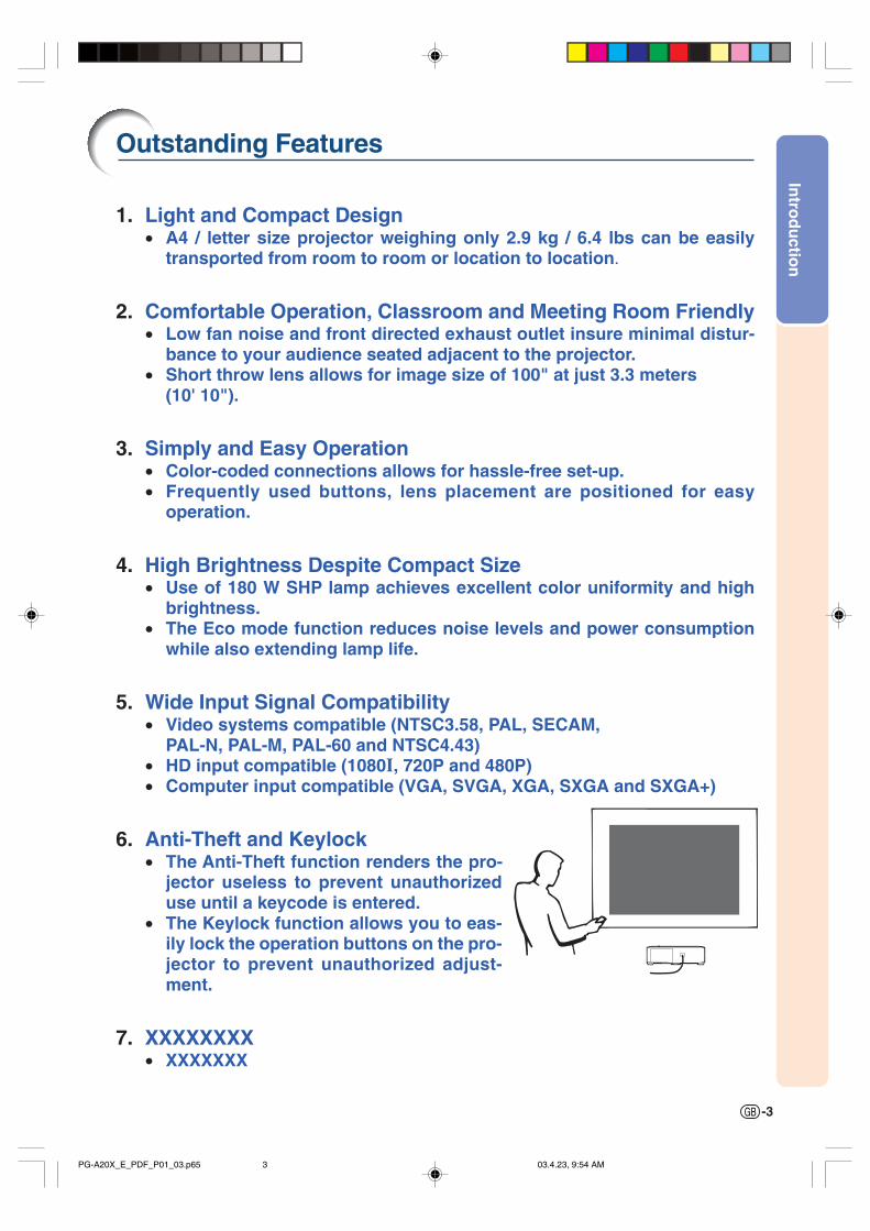
6. Anti-Theft and Keylock• The Anti-Theft function renders the pro-
jector useless to prevent unauthorizeduse until a keycode is entered.
• The Keylock function allows you to eas-ily lock the operation buttons on the pro-jector to prevent unauthorized adjust-ment.
7. XXXXXXXX• XXXXXXX
PG-A20X_E_PDF_P01_03.p65 03.4.23, 9:54 AM3
-4
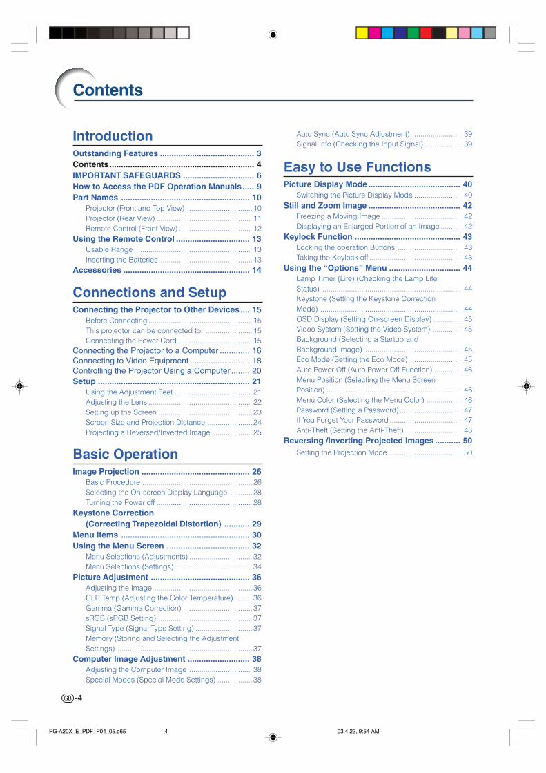
Contents
Auto Sync (Auto Sync Adjustment) ........................ 39Signal Info (Checking the Input Signal) ................... 39
Easy to Use FunctionsPicture Display Mode ........................................ 40
Switching the Picture Display Mode ........................40Still and Zoom Image ........................................ 42
Freezing a Moving Image ....................................... 42Displaying an Enlarged Portion of an Image ...........42
Keylock Function .............................................. 43Locking the operation Buttons ................................43Taking the Keylock off ..............................................43
Using the “Options” Menu ............................... 44Lamp Timer (Life) (Checking the Lamp LifeStatus) .................................................................... 44Keystone (Setting the Keystone CorrectionMode) ......................................................................44OSD Display (Setting On-screen Display) ...............45Video System (Setting the Video System) ...............45Background (Selecting a Startup andBackground Image) ................................................ 45Eco Mode (Setting the Eco Mode) ..........................45Auto Power Off (Auto Power Off Function) ............. 46Menu Position (Selecting the Menu ScreenPosition) .................................................................. 46Menu Color (Selecting the Menu Color) ................. 46Password (Setting a Password) .............................. 47If You Forget Your Password ................................... 47Anti-Theft (Setting the Anti-Theft) ............................48
Reversing /Inverting Projected Images ........... 50Setting the Projection Mode ................................... 50
IntroductionOutstanding Features ......................................... 3Contents ............................................................... 4IMPORTANT SAFEGUARDS ............................... 6How to Access the PDF Operation Manuals ..... 9Part Names ........................................................ 10
Projector (Front and Top View) ................................ 10Projector (Rear View) .............................................. 11Remote Control (Front View) ................................... 12
Using the Remote Control ................................ 13Usable Range ......................................................... 13Inserting the Batteries .............................................13
Accessories ....................................................... 14
Connections and SetupConnecting the Projector to Other Devices.... 15
Before Connecting .................................................. 15This projector can be connected to: ....................... 15Connecting the Power Cord ................................... 15
Connecting the Projector to a Computer ............. 16Connecting to Video Equipment .......................... 18Controlling the Projector Using a Computer ........ 20Setup .................................................................. 21
Using the Adjustment Feet ..................................... 21Adjusting the Lens .................................................. 22Setting up the Screen ..............................................23Screen Size and Projection Distance ......................24Projecting a Reversed/Inverted Image ................... 25
Basic OperationImage Projection ............................................... 26
Basic Procedure ......................................................26Selecting the On-screen Display Language ...........28Turning the Power off .............................................. 28
Keystone Correction(Correcting Trapezoidal Distortion) ........... 29
Menu Items ........................................................ 30Using the Menu Screen .................................... 32
Menu Selections (Adjustments) .............................. 32Menu Selections (Settings) ..................................... 34
Picture Adjustment ........................................... 36Adjusting the Image ................................................36CLR Temp (Adjusting the Color Temperature) ........ 36Gamma (Gamma Correction) .................................. 37sRGB (sRGB Setting) ..............................................37Signal Type (Signal Type Setting) ............................37Memory (Storing and Selecting the AdjustmentSettings) ..................................................................37
Computer Image Adjustment ........................... 38Adjusting the Computer Image .............................. 38Special Modes (Special Mode Settings) ................. 38
PG-A20X_E_PDF_P04_05.p65 03.4.23, 9:54 AM4

Intro
du
ction
-5
AppendixCarrying the Projector ...................................... 51
How to Use the Carrying Case ................................ 51
Maintenance ...................................................... 52Replacing the Air Filter ..................................... 53
Cleaning and Replacing the Air Filter ..................... 53
Maintenance Indicators .................................... 55Regarding the Lamp ......................................... 57
Lamp ...................................................................... 57Caution Concerning the Lamp ................................ 57Replacing the Lamp ................................................57Removing and Installing the Lamp Unit ................. 58Resetting the Lamp Timer .......................................59
Connecting Pin Assignments .......................... 60RS-232C Specifications and
Command Settings ...................................... 61Computer Compatibility Chart ......................... 62Troubleshooting ................................................ 63For SHARP Assistance ..................................... 65Specifications .................................................... 66Dimensions ........................................................ 67Glossary ............................................................. 68Index ................................................................... 69
PG-A20X_E_PDF_P04_05.p65 03.4.23, 9:54 AM5
-6
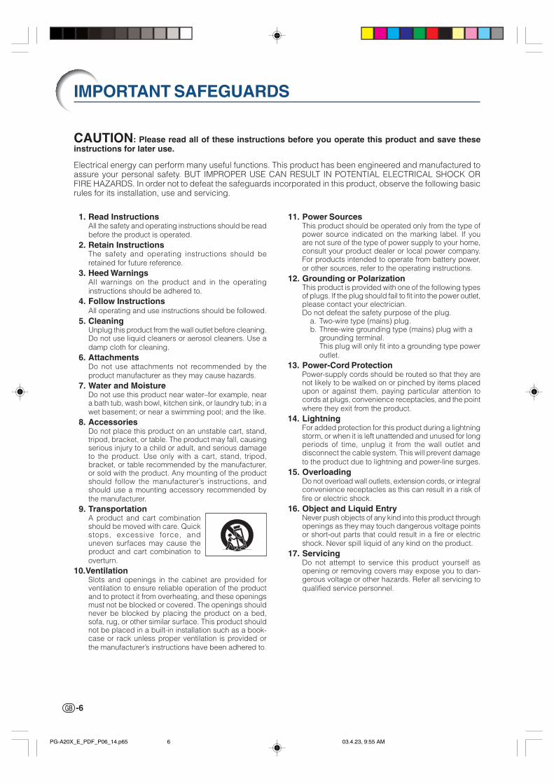
1. Read InstructionsAll the safety and operating instructions should be readbefore the product is operated.
2. Retain InstructionsThe safety and operating instructions should beretained for future reference.
3. Heed WarningsAll warnings on the product and in the operatinginstructions should be adhered to.
4. Follow InstructionsAll operating and use instructions should be followed.
5. CleaningUnplug this product from the wall outlet before cleaning.Do not use liquid cleaners or aerosol cleaners. Use adamp cloth for cleaning.
6. AttachmentsDo not use attachments not recommended by theproduct manufacturer as they may cause hazards.
7. Water and MoistureDo not use this product near water–for example, neara bath tub, wash bowl, kitchen sink, or laundry tub; in awet basement; or near a swimming pool; and the like.
8. AccessoriesDo not place this product on an unstable cart, stand,tripod, bracket, or table. The product may fall, causingserious injury to a child or adult, and serious damageto the product. Use only with a cart, stand, tripod,bracket, or table recommended by the manufacturer,or sold with the product. Any mounting of the productshould follow the manufacturer’s instructions, andshould use a mounting accessory recommended bythe manufacturer.
9. TransportationA product and cart combinationshould be moved with care. Quickstops, excessive force, anduneven surfaces may cause theproduct and cart combination tooverturn.
10.VentilationSlots and openings in the cabinet are provided forventilation to ensure reliable operation of the productand to protect it from overheating, and these openingsmust not be blocked or covered. The openings shouldnever be blocked by placing the product on a bed,sofa, rug, or other similar surface. This product shouldnot be placed in a built-in installation such as a book-case or rack unless proper ventilation is provided orthe manufacturer’s instructions have been adhered to.
IMPORTANT SAFEGUARDS
11. Power SourcesThis product should be operated only from the type ofpower source indicated on the marking label. If youare not sure of the type of power supply to your home,consult your product dealer or local power company.For products intended to operate from battery power,or other sources, refer to the operating instructions.
12. Grounding or PolarizationThis product is provided with one of the following typesof plugs. If the plug should fail to fit into the power outlet,please contact your electrician.Do not defeat the safety purpose of the plug.
a. Two-wire type (mains) plug.b. Three-wire grounding type (mains) plug with a
grounding terminal.This plug will only fit into a grounding type poweroutlet.
13. Power-Cord ProtectionPower-supply cords should be routed so that they arenot likely to be walked on or pinched by items placedupon or against them, paying particular attention tocords at plugs, convenience receptacles, and the pointwhere they exit from the product.
14. LightningFor added protection for this product during a lightningstorm, or when it is left unattended and unused for longperiods of time, unplug it from the wall outlet anddisconnect the cable system. This will prevent damageto the product due to lightning and power-line surges.
15. OverloadingDo not overload wall outlets, extension cords, or integralconvenience receptacles as this can result in a risk offire or electric shock.
16. Object and Liquid EntryNever push objects of any kind into this product throughopenings as they may touch dangerous voltage pointsor short-out parts that could result in a fire or electricshock. Never spill liquid of any kind on the product.
17. ServicingDo not attempt to service this product yourself asopening or removing covers may expose you to dan-gerous voltage or other hazards. Refer all servicing toqualified service personnel.
CAUTION: Please read all of these instructions before you operate this product and save theseinstructions for later use.
Electrical energy can perform many useful functions. This product has been engineered and manufactured toassure your personal safety. BUT IMPROPER USE CAN RESULT IN POTENTIAL ELECTRICAL SHOCK ORFIRE HAZARDS. In order not to defeat the safeguards incorporated in this product, observe the following basicrules for its installation, use and servicing.
PG-A20X_E_PDF_P06_14.p65 03.4.23, 9:55 AM6

Intro
du
ction
-7
18. Damage Requiring ServiceUnplug this product from the wall outlet and referservicing to qualified service personnel under thefollowing conditions:
a. When the power-supply cord or plug is damaged.b. If liquid has been spilled, or objects have fallen
into the product.c. If the product has been exposed to rain or water.d. If the product does not operate normally by
following the operating instructions. Adjust onlythose controls that are covered by the operatinginstructions, as an improper adjustment of othercontrols may result in damage and will oftenrequire extensive work by a qualified technicianto restore the product to normal operation.
e. If the product has been dropped or damaged inany way.
f. When the product exhibits a distinct change inperformance, this indicates a need for service.
• Microsoft and Windows are registered trademarks of Microsoft Corporation in the United States and/orother countries.
• PC/AT is a registered trademark of International Business Machines Corporation in the United States.• Adobe Acrobat is a trademark of Adobe Systems Incorporated.• Macintosh is a registered trademark of Apple Computer, Inc. in the United States and/or other countries.• All other company or product names are trademarks or registered trademarks of their respective compa-
nies.
19. Replacement PartsWhen replacement parts are required, be sure theservice technician has used replacement partsspecified by the manufacturer or have the samecharacteristics as the original part. Unauthorizedsubstitutions may result in fire, electric shock, or otherhazards.
20. Safety CheckUpon completion of any service or repairs to thisproduct, ask the service technician to perform safetychecks to determine that the product is in properoperating condition.
21. Wall or Ceiling MountingThis product should be mounted to a wall or ceilingonly as recommended by the manufacturer.
22. HeatThis product should be situated away from heat sourcessuch as radiators, heat registers, stoves, or otherproducts (including amplifiers) that produce heat.
PG-A20X_E_PDF_P06_14.p65 03.4.23, 9:55 AM7

-8
IMPORTANT SAFEGUARDS
Be sure to read the following safeguards when setting upyour projector.
Caution concerning the lamp unit Potential hazard of glass particles if
lamp ruptures. In case of lamp rupture,contact your nearest Sharp AuthorizedProjector Dealer or Service Center fora replacement.See “Replacing the Lamp” on page 57.
Caution concerning the setup of the projector For minimal servicing and to maintain high image qual-
ity, SHARP recommends that this projector be installedin an area free from humidity, dust and cigarette smoke.When the projector is subjected to these environments,the lens must be cleaned more often. As long as theprojector is regularly cleaned, use in these environ-ments will not reduce the overall operation life of theunit. Internal cleaning should only be performed by aSharp Authorized Projector Dealer or Service Center.
Do not set up the projector in places exposed todirect sunlight or bright light. Position the screen so that it is not in direct sunlight or
room light. Light falling directly on the screen washesout the colors, making viewing difficult. Close the cur-tains and dim the lights when setting up the screen in asunny or bright room.
The projector may be safely tilted to a maximumangle of 12 degrees. Placement should be within ±12 degrees of horizontal.
Do not subject the projector to hard impact and/or vibration. Take care with the lens so as not to hit or damage the
surface of the lens.
Rest your eyes occasionally. Continuously watching the screen for long hours will
cause eye strain. Be sure to occasionally rest your eyes.
Avoid locations with extremes of temperature. The operating temperature of the projector is from 41°F
to 95°F (+5°C to +35°C). The storage temperature of the projector is from
–4°F to 140°F (–20°C to +60°C).
Do not block the exhaust and intake vents. Allow at least 7 7/8 inches (20 cm) of space between
the exhaust vent and the nearest wall or obstruction.
Be sure that the intake vent and the exhaust vent arenot obstructed.
If the cooling fan becomes obstructed, a protection cir-cuit will automatically put the projector into the standbymode. This does not indicate a malfunction. Removethe projector power cord from the wall outlet and waitat least 10 minutes. Place the projector where the intakeand exhaust vents are not blocked, plug the power cordback in and turn on the projector. This will return theprojector to the normal operating condition.
Caution regarding transportation of the projec-tor When transporting the projector, be sure not to subject
it to hard impact and/or vibration, as this can result indamage. Take extra care with the lens. Before movingthe projector, be sure to unplug the power cord fromthe wall outlet, and disconnect any other cables con-nected to it.
Other connected equipment When connecting a computer or other audio-visual
equipment to the projector, make the connections AF-TER unplugging the power cord of the projector fromthe AC outlet and turning off the equipment to be con-nected.
Please read the operation manuals of the projector andthe equipment to be connected for instructions on howto make the connections.
Using the projector in other countries The power supply voltage and the shape of the plug
may vary depending on the region or country you areusing the projector in. When using the projector over-seas, be sure to use an appropriate power cord for thecountry you are in.
Temperature monitor function If the projector starts to overheat
due to setup problems or block-age of the air vents, “ ” and“ ” will illuminate in the lower left corner of thepicture. If the temperature continues to rise, the lampwill turn off, the temperature warning indicator on theprojector will blink, and after a 90-second cooling-offperiod the projector will enter the standby mode. Referto “Maintenance Indicators” on page 55 for details.
Info
• The cooling fan regulates the internal temperature, andits performance is automatically controlled. The soundof the fan may change during projector operation dueto changes in the fan speed. This does not indicatemalfunction.
• Do not unplug the power cord during projection or cool-ing fan operation. This can cause damage due to risein internal temperature, as the cooling fan also stops.
BQC-PGA20X//1
PG-A20X_E_PDF_P06_14.p65 03.4.23, 9:55 AM8
Intro
du
ction
-9
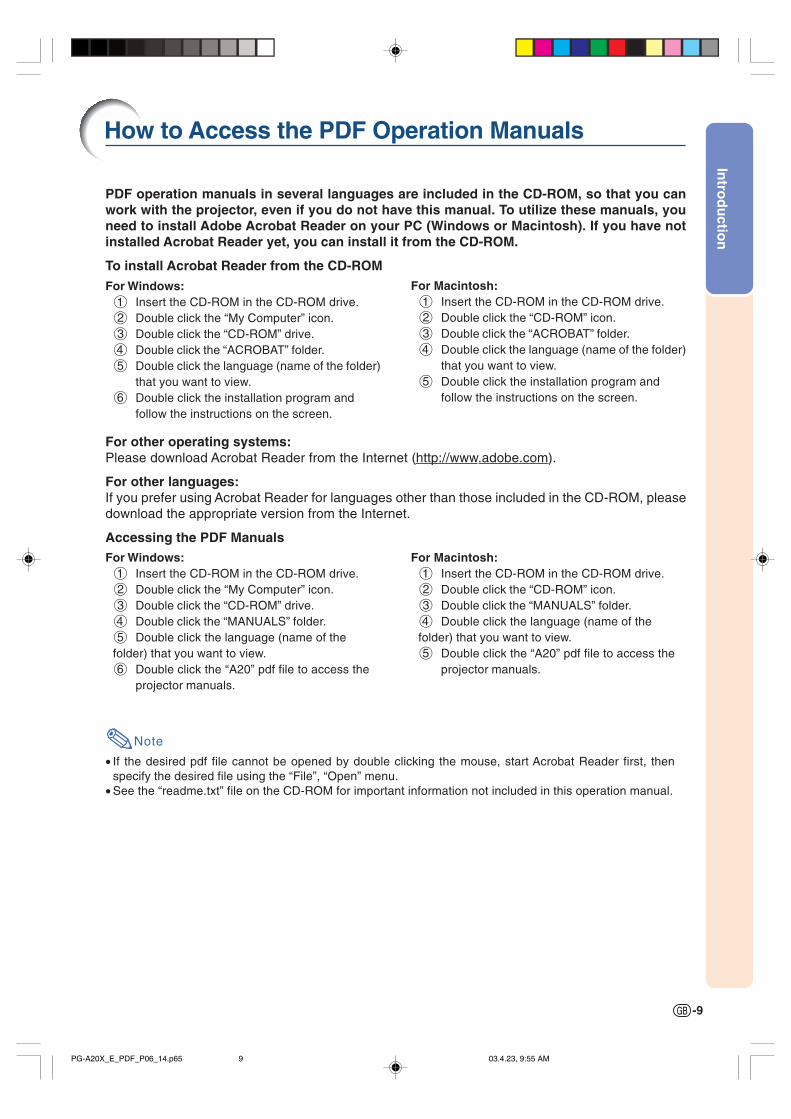
PDF operation manuals in several languages are included in the CD-ROM, so that you canwork with the projector, even if you do not have this manual. To utilize these manuals, youneed to install Adobe Acrobat Reader on your PC (Windows or Macintosh). If you have notinstalled Acrobat Reader yet, you can install it from the CD-ROM.
To install Acrobat Reader from the CD-ROM
For Windows:1 Insert the CD-ROM in the CD-ROM drive.2 Double click the “My Computer” icon.3 Double click the “CD-ROM” drive.4 Double click the “ACROBAT” folder.5 Double click the language (name of the folder)
that you want to view.6 Double click the installation program and
follow the instructions on the screen.
For Macintosh:1 Insert the CD-ROM in the CD-ROM drive.2 Double click the “CD-ROM” icon.3 Double click the “ACROBAT” folder.4 Double click the language (name of the folder)
that you want to view.5 Double click the installation program and
follow the instructions on the screen.
For other operating systems:Please download Acrobat Reader from the Internet (http://www.adobe.com).
For other languages:If you prefer using Acrobat Reader for languages other than those included in the CD-ROM, pleasedownload the appropriate version from the Internet.
Accessing the PDF ManualsFor Windows:1 Insert the CD-ROM in the CD-ROM drive.2 Double click the “My Computer” icon.3 Double click the “CD-ROM” drive.4 Double click the “MANUALS” folder.5 Double click the language (name of thefolder) that you want to view.6 Double click the “A20” pdf file to access the
projector manuals.
Note
• If the desired pdf file cannot be opened by double clicking the mouse, start Acrobat Reader first, thenspecify the desired file using the “File”, “Open” menu.
• See the “readme.txt” file on the CD-ROM for important information not included in this operation manual.
For Macintosh:1 Insert the CD-ROM in the CD-ROM drive.2 Double click the “CD-ROM” icon.3 Double click the “MANUALS” folder.4 Double click the language (name of thefolder) that you want to view.5 Double click the “A20” pdf file to access the
projector manuals.
How to Access the PDF Operation Manuals
PG-A20X_E_PDF_P06_14.p65 03.4.23, 9:55 AM9
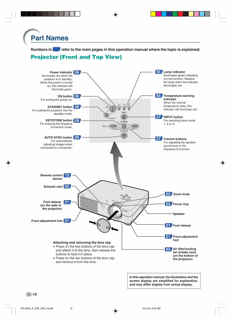
-10
26
26 55
55
2729
39 27
13
52
21
21
ON buttonFor turning the power on.
28STANDBY buttonFor putting the projector into the
standby mode.
Power indicatorIlluminates red when the
projector is in standby. When the power is turned
on, this indicator will illuminate green.
Lamp indicatorIlluminates green indicating normal function. Replace the lamp when the indicator illuminates red.
Temperature warning indicatorWhen the internal temperature rises, this indicator will illuminate red.
Remote controlsensor
53
INPUT buttonFor switching input mode 1, 2 or 3.
KEYSTONE buttonFor entering the Keystone
Correction mode.
AUTO SYNC buttonFor automatically
adjusting images when connected to a computer.
Volume buttonsFor adjusting the speaker sound level or the Keystone Correction.
22 Zoom knob
22 Focus ring
Speaker
21 Foot release
21 Front adjustmentfoot
Front adjustment foot
Air filter/cooling fan (Intake vent) (on the bottom of the projector)
Exhaust vent
Foot release (on the side of
the projector)
Numbers in refer to the main pages in this operation manual where the topic is explained.
Projector (Front and Top View)
Part Names
Attaching and removing the lens cap• Press on the two buttons of the lens cap
and attach it to the lens, then release thebuttons to lock it in place.
• Press on the two buttons of the lens capand remove it from the lens.
In this operation manual, the illustration and thescreen display are simplified for explanation,and may differ slightly from actual display.
PG-A20X_E_PDF_P06_14.p65 03.4.23, 9:55 AM10
Intro
du
ction
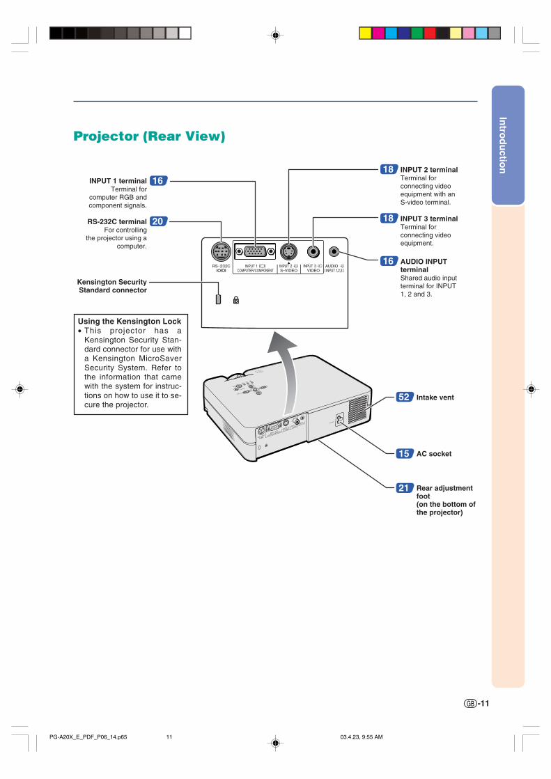
-11
15
52
AC socket
21 Rear adjustment foot(on the bottom of the projector)
Intake vent
16
Kensington Security Standard connector
INPUT 1 terminalTerminal for
computer RGB and component signals.
20RS-232C terminalFor controlling
the projector using a computer.
16 AUDIO INPUT terminalShared audio input terminal for INPUT 1, 2 and 3.
18 INPUT 2 terminalTerminal for connecting video equipment with an S-video terminal.
18 INPUT 3 terminalTerminal for connecting video equipment.
Projector (Rear View)
Using the Kensington Lock• This projector has a
Kensington Security Stan-dard connector for use witha Kensington MicroSaverSecurity System. Refer tothe information that camewith the system for instruc-tions on how to use it to se-cure the projector.
PG-A20X_E_PDF_P06_14.p65 03.4.23, 9:55 AM11

-12
Part Names
Numbers in refer to the main pages in this operation manual where the topic is explained.
Remote Control (Front View)
28STANDBY buttonFor putting the projector into the
standby mode.32 MENU button
For displaying adjustment and setting screens.
ON buttonFor turning the power on.
32 Adjustment buttons(', ", \, |)For selecting menu items.
29KEYSTONE buttonFor entering the Keystone
Correction mode.
29UNDO buttonFor undoing an operation or
returning to the previous display.
FORWARD/BACK buttonsSame function as the [Page Down] and [Page Up] keys on a computer keyboard when using the optional
Remote Receiver (AN-MR1EL).
27
39
42ENLARGE (Enlarge/Reduce) buttons
For enlarging or reducing part of the image.
AUTO SYNC buttonFor automatically adjusting images
when connected to a computer.
Volume buttonsFor adjusting the speaker sound level.
INPUT buttonsFor switching to the respective
input modes.
42
27
FREEZE buttonFor freezing images.
RESIZE buttonFor switching the screen size (NORMAL, BORDER, etc).
AV MUTE buttonFor temporarily displaying the black screen and turning off the sound.
40
27
26
35 ENTER buttonFor setting items selected or adjusted on the menu.
PG-A20X_E_PDF_P06_14.p65 03.4.23, 9:55 AM12

Intro
du
ction
-13
Using the Remote Control
Inserting the BatteriesThe batteries (two R-6 batteries (“AA” size, UM/SUM-3, HP-7 or similar)) are supplied in thepackage.
1 Press the mark on the coverand slide it in the direction of thearrow.
2 Insert the batteries.• Insert the batteries making sure the po-
larities correctly match the and marks inside the battery compartment.
3 Attach the cover and slide it un-til it clicks into place.
Incorrect use of the batteries may cause them to leak or explode. Please follow the precautions below.
Caution• Insert the batteries making sure the polarities correctly match the and marks inside the battery compart-
ment.• Batteries of different types have different properties, therefore do not mix batteries of different types.• Do not mix new and old batteries.
This may shorten the life of new batteries or may cause old batteries to leak.• Remove the batteries from the remote control once they have run out, as leaving them in can cause them to leak.
Battery fluid from leaked batteries is harmful to skin, therefore be sure to first wipe them and then remove themusing a cloth.
• The batteries included with this projector may run down in a short period, depending on how they are kept. Besure to replace them as soon as possible with new batteries.
• Remove the batteries from the remote control if you will not be using the remote control for a long time.
Usable Range The remote control can be used to control
the projector within the ranges shown inthe illustration.
Note• The signal from the remote control can be re-
flected off a screen for easy operation. How-ever, the effective distance of the signal maydiffer depending on the screen material.
When using the remote control:• Be sure not to drop, expose to moisture or high
temperature.• The remote control may malfunction under a
fluorescent lamp. In this case, move the pro-jector away from the fluorescent lamp.
23' (7 m)30°
30°
45°
Remote control
Remote control sensor
Remotecontrolsignaltransmitters
PG-A20X_E_PDF_P06_14.p65 03.4.23, 9:55 AM13
-14
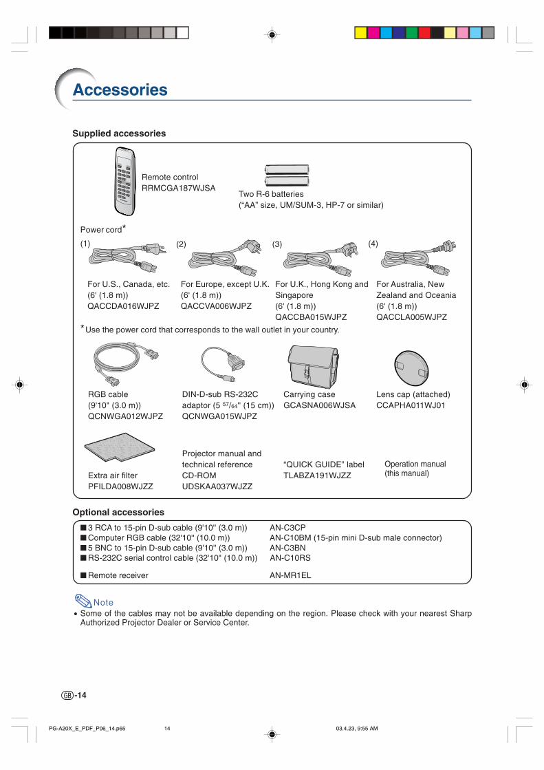
Accessories
Remote controlRRMCGA187WJSA
Two R-6 batteries(“AA” size, UM/SUM-3, HP-7 or similar)
Power cord*
For U.S., Canada, etc.(6' (1.8 m))QACCDA016WJPZ
For Europe, except U.K.(6' (1.8 m))QACCVA006WJPZ
*Use the power cord that corresponds to the wall outlet in your country.
3 RCA to 15-pin D-sub cable (9'10'' (3.0 m)) AN-C3CP Computer RGB cable (32'10'' (10.0 m)) AN-C10BM (15-pin mini D-sub male connector) 5 BNC to 15-pin D-sub cable (9'10'' (3.0 m)) AN-C3BN RS-232C serial control cable (32'10" (10.0 m)) AN-C10RS
Remote receiver AN-MR1EL
Note• Some of the cables may not be available depending on the region. Please check with your nearest Sharp
Authorized Projector Dealer or Service Center.
Projector manual andtechnical referenceCD-ROMUDSKAA037WJZZ
(1) (2) (3) (4)
Extra air filterPFILDA008WJZZ
Lens cap (attached)CCAPHA011WJ01
Supplied accessories
Optional accessories
RGB cable(9'10" (3.0 m))QCNWGA012WJPZ
DIN-D-sub RS-232Cadaptor (5 57/64'' (15 cm))QCNWGA015WJPZ
For U.K., Hong Kong andSingapore(6' (1.8 m))QACCBA015WJPZ
For Australia, NewZealand and Oceania(6' (1.8 m))QACCLA005WJPZ
Carrying caseGCASNA006WJSA
“QUICK GUIDE” labelTLABZA191WJZZ
Operation manual(this manual)
PG-A20X_E_PDF_P06_14.p65 03.4.23, 9:55 AM14
Co
nn
ection
s and
Setu
p
-15
Connecting the Projector to Other Devices
Before Connecting
Note
• Before connecting, be sure to unplug the power cord of the projector from the AC outlet and turn off thedevices to be connected. After making all connections, turn on the projector and then the other devices.When connecting a computer, be sure that it is the last device to be turned on after all the connections aremade.
• Be sure to read the operation manuals of the devices to be connected before making connections.
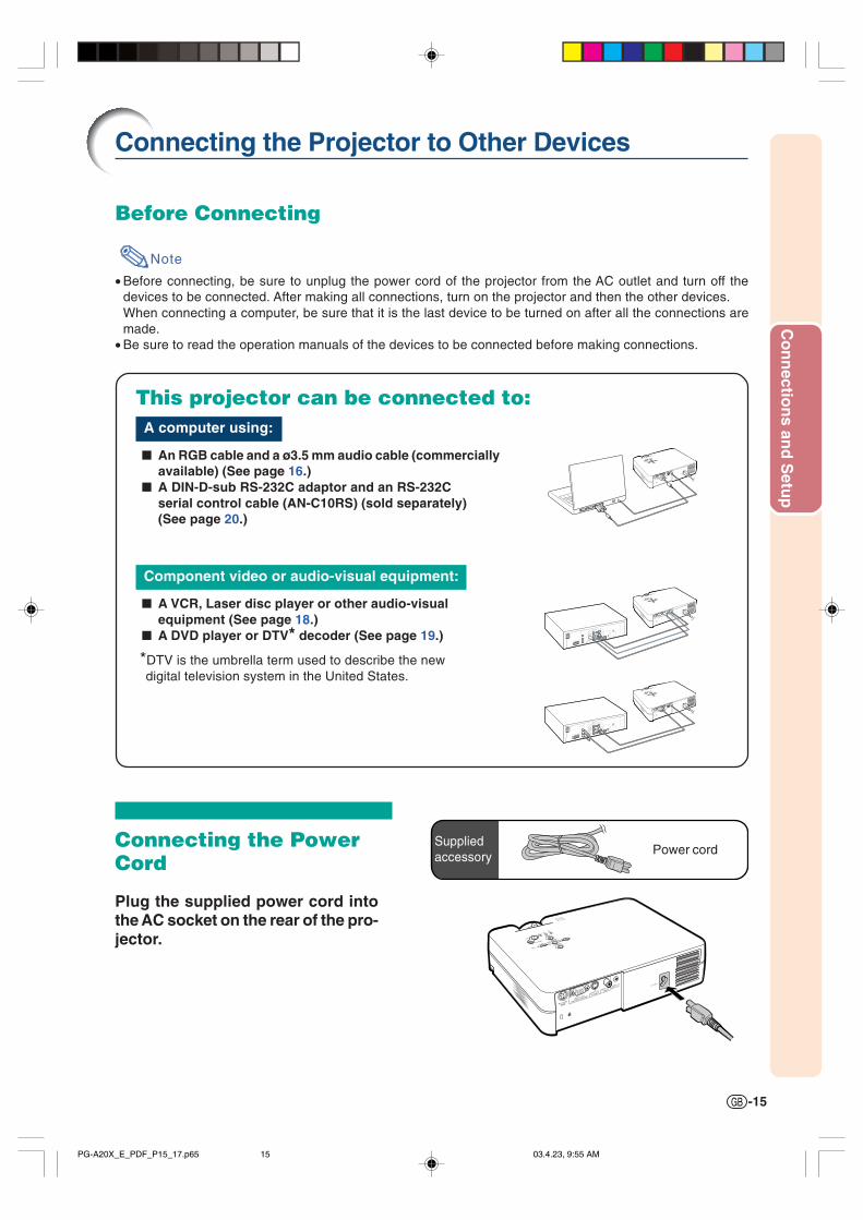
This projector can be connected to:A computer using:
An RGB cable and a ø3.5 mm audio cable (commerciallyavailable) (See page 16.)
A DIN-D-sub RS-232C adaptor and an RS-232Cserial control cable (AN-C10RS) (sold separately)(See page 20.)
Component video or audio-visual equipment:
A VCR, Laser disc player or other audio-visualequipment (See page 18.)
A DVD player or DTV* decoder (See page 19.)
*DTV is the umbrella term used to describe the newdigital television system in the United States.
Connecting the PowerCord
Plug the supplied power cord intothe AC socket on the rear of the pro-jector.
Power cordSuppliedaccessory
PG-A20X_E_PDF_P15_17.p65 03.4.23, 9:55 AM15
-16
Connecting the Projector to a Computer
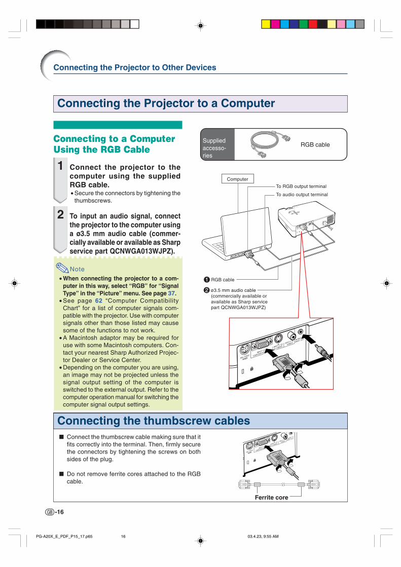
Connecting the thumbscrew cables Connect the thumbscrew cable making sure that it
fits correctly into the terminal. Then, firmly securethe connectors by tightening the screws on bothsides of the plug.
Do not remove ferrite cores attached to the RGBcable.
Ferrite core
Connecting to a ComputerUsing the RGB Cable
1 Connect the projector to thecomputer using the suppliedRGB cable.• Secure the connectors by tightening the
thumbscrews.
2 To input an audio signal, connectthe projector to the computer usinga ø3.5 mm audio cable (commer-cially available or available as Sharpservice part QCNWGA013WJPZ).
Note• When connecting the projector to a com-
puter in this way, select “RGB” for “SignalType” in the “Picture” menu. See page 37.
• See page 62 “Computer CompatibilityChart” for a list of computer signals com-patible with the projector. Use with computersignals other than those listed may causesome of the functions to not work.
• A Macintosh adaptor may be required foruse with some Macintosh computers. Con-tact your nearest Sharp Authorized Projec-tor Dealer or Service Center.
• Depending on the computer you are using,an image may not be projected unless thesignal output setting of the computer isswitched to the external output. Refer to thecomputer operation manual for switching thecomputer signal output settings.
Suppliedaccesso-ries
Connecting the Projector to Other Devices
RGB cable
Computer
2ø3.5 mm audio cable(commercially available oravailable as Sharp servicepart QCNWGA013WJPZ)
1RGB cable
To RGB output terminal
To audio output terminal
PG-A20X_E_PDF_P15_17.p65 03.4.23, 9:55 AM16

Co
nn
ection
s and
Setu
p
-17
“Plug and Play” function (when connecting to a 15-pin terminal) This projector is compatible with VESA-standard DDC 1/DDC 2B. The projector and a VESA DDC
compatible computer will communicate their setting requirements, allowing for quick and easy setup. Before using the “Plug and Play” function, be sure to turn on the projector first and the connected
computer last.
Note
• The DDC “Plug and Play” function of this projector operates only when used in conjunction with a VESADDC compatible computer.
PG-A20X_E_PDF_P15_17.p65 03.4.23, 9:55 AM17

-18
Connecting to Video Equipment
Connecting the Projector to Other Devices
Connecting to VideoEquipment Using anS-video, a CompositeVideo or an Audio CableUsing an S-video, video, or audio cable, a VCR,laser disc player or other audio-visual equipmentcan be connected to INPUT 2, INPUT 3 and AU-DIO input terminals.
1 Connect the projector to thevideo equipment using an S-video cable or a composite videocable (both commercially avail-able).
2 Connect the projector to thevideo equipment using a ø3.5mm minijack to RCA audio cable(commercially available).
Note
• The INPUT 2 (S-VIDEO) terminal uses avideo signal system in which the picture isseparated into color and luminance signalsto realize a higher-quality image. To view ahigher-quality image, use a commerciallyavailable S-video cable to connect the IN-PUT 2 terminal on the projector and the S-video output terminal on the video equip-ment.
• A ø3.5 mm minijack to RCA audio cable(commercially available) is required for au-dio input.
To S-video output terminal
To video output terminal
To audio output terminal
VCR or other audio-visual equipment
1S-video cable(commercially available)
1Composite video cable(commercially available)
2ø3.5 mm minijack to RCA audio cable(commercially available)
PG-A20X_E_PDF_P18_20.p65 03.4.23, 9:56 AM18
Co
nn
ection
s and
Setu
p
-19
Optionalcable
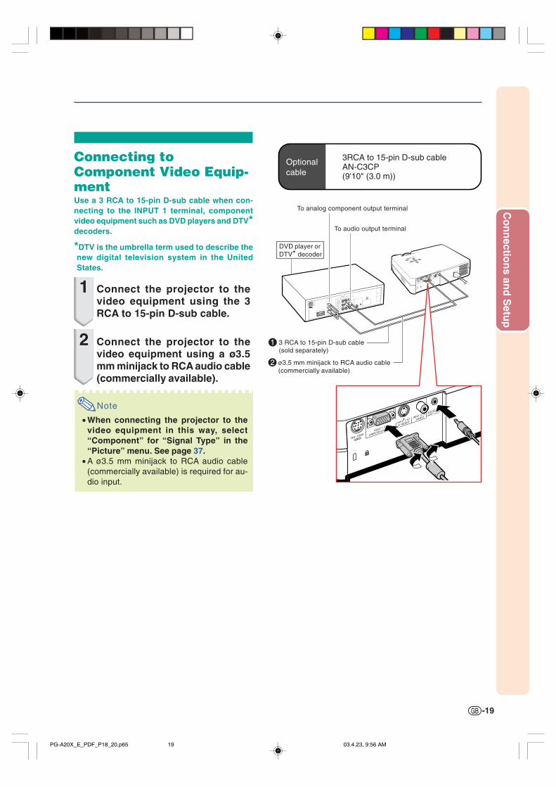
3RCA to 15-pin D-sub cableAN-C3CP(9'10" (3.0 m))
To analog component output terminal
To audio output terminal
DVD player orDTV* decoder
Connecting toComponent Video Equip-mentUse a 3 RCA to 15-pin D-sub cable when con-necting to the INPUT 1 terminal, componentvideo equipment such as DVD players and DTV*decoders.
*DTV is the umbrella term used to describe thenew digital television system in the UnitedStates.
1 Connect the projector to thevideo equipment using the 3RCA to 15-pin D-sub cable.
2 Connect the projector to thevideo equipment using a ø3.5mm minijack to RCA audio cable(commercially available).
Note
• When connecting the projector to thevideo equipment in this way, select“Component” for “Signal Type” in the“Picture” menu. See page 37.
• A ø3.5 mm minijack to RCA audio cable(commercially available) is required for au-dio input.
1 3 RCA to 15-pin D-sub cable(sold separately)
2ø3.5 mm minijack to RCA audio cable(commercially available)
PG-A20X_E_PDF_P18_20.p65 03.4.23, 9:56 AM19

-20
Connecting to aComputer Using a DIN-D-sub RS-232C Adaptorand an RS-232C SerialControl CableWhen the RS-232C terminal on the projector isconnected to a computer with a DIN-D-sub RS-232C adaptor and an RS-232C serial controlcable (cross type, sold separately), the computercan be used to control the projector and checkthe status of the projector. See page 61 for de-tails.
1 Connect the supplied DIN-D-subRS-232C adaptor to an RS-232Cserial control cable (sold sepa-rately).
2 Use the above cables to connectthe projector and the computer.
Note
• Do not connect or disconnect an RS-232Cserial control cable to or from the computerwhile it is on. This may damage your com-puter.
• The RS-232C function may not operate ifyour computer terminal is not correctly setup. Refer to the operation manual of thecomputer for details.
• See page 60 for connection of an RS-232Cserial control cable.
Optionalcable
RS-232C serial control cableAN-C10RS(32'10" (10.0 m))
To RS-232C terminal
DIN-D-subRS-232C adaptor
Suppliedaccessory
Computer
RS-232C serialcontrol cable(sold separately)
DIN-D-subRS-232Cadaptor
Controlling the Projector Using a Computer
Connecting the Projector to Other Devices
PG-A20X_E_PDF_P18_20.p65 03.4.23, 9:56 AM20

Co
nn
ection
s and
Setu
p
-21
Setup
Using the AdjustmentFeetThe height of the projector can be adjusted us-ing the adjustment feet at the front and rear ofthe projector when the surface the projector isplaced on is uneven or when the screen isslanted.The projection of the image can be made higherby adjusting the projector when it is in a lowerplace than the screen.
1 While pressing the foot releaseson both sides, lift the projectorto adjust its height and then re-move your fingers from the footreleases.
2 Rotate the adjustment feet at thefront of the projector for fineadjustment.• You can adjust the projection by using
the rear adjustment foot on the bottomof the projector when the projector is po-sitioned at the higher place than thescreen.
Note
• The Keystone Correction will be automaticallyperformed when the projector is tilted. If youwant to adjust the Keystone Correctionmanually, see page 29. (For details on set-ting of the Keystone Correction, see page 44.)
• When returning the projector to its originalposition, hold the projector firmly, press thefoot releases and then gently lower it.
• The projector is adjustable up to approxi-mately 12 degrees at the front and 3 degreesat the back from the standard position.
Info
• Do not press the foot releases when the ad-justment feet are extended without firmlyholding the projector.
• Do not hold the lens when lifting or lower-ing the projector.
• When lowering the projector, be careful notto get your fingers caught in the area betweenthe adjustment foot and the projector.
Front adjustment feet
Rear adjustment foot(on the bottom)
Foot release(on the other side ofthe projector as well)
PG-A20X_E_PDF_P21_25.p65 03.4.23, 9:56 AM21
-22
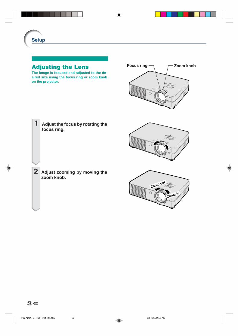
Adjusting the LensThe image is focused and adjusted to the de-sired size using the focus ring or zoom knobon the projector.
1 Adjust the focus by rotating thefocus ring.
2 Adjust zooming by moving thezoom knob.
Setup
Zoom in
Zoom out
Focus ring Zoom knob
PG-A20X_E_PDF_P21_25.p65 03.4.23, 9:56 AM22

Co
nn
ection
s and
Setu
p
-23
90°
90°
Example of standard setup
Setting up the ScreenPosition the projector perpendicular to the screen with all feet flat and level to achieve an optimal image.
Note
• The projector lens should be centered in the middle of the screen. If the horizontal line passing through thelens center is not perpendicular to the screen, the image will be distorted, making viewing difficult.
• For an optimal image, position the screen so that it is not in direct sunlight or room light. Light falling directlyon the screen washes out the colors, making viewing difficult. Close the curtains and dim the lights whensetting up the screen in a sunny or bright room.
• A polarizing screen cannot be used with this projector.
Standard Setup (Front Projection) Place the projector at the required distance from
the screen according to the desired picture size.(See page 24.)
Side View
Top View
• The distance from the screen to the projectormay vary depending on the size of the screen.
P.24
• The default setting can be used, when placing theprojector in front of the screen. If the projected im-age is reversed or inverted, readjust the setting to“Front” in the “PRJ Mode” menu. P.50
• Place the projector so that an imaginary horizontalline that passes through the center of the lens isperpendicular to the screen.
Audience
PG-A20X_E_PDF_P21_25.p65 03.4.23, 9:56 AM23
-24
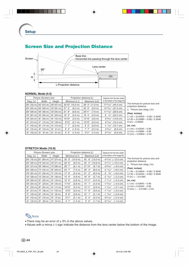
STRETCH Mode (16:9)Picture (Screen) size Projection distance [L] Distance from the lens center
Diag. [χ] Width Height Minimum [L1] Maximum [L2] to the bottom of the image [H]
300" (762 cm) 261" (664 cm) 147" (374 cm) 35' 9" (10.9 m) 42' 8" (13.0 m) –4 47/64" (–12.0 cm)
250" (635 cm) 218" (553 cm) 123" (311 cm) 29' 6" (9.0 m) 35' 5" (10.8 m) –3 15/16" (–10.0 cm)
225" (572 cm) 196" (498 cm) 110" (280 cm) 26' 7" (8.1 m) 31'10" (9.7 m) –3 35/64" (–9.0 cm)
200" (508 cm) 174" (443 cm) 98" (249 cm) 23' 7" (7.2 m) 28' 3" (8.6 m) –3 5/32" (–8.0 cm)
150" (381 cm) 131" (332 cm) 74" (187 cm) 17' 9" (5.4 m) 21' 2" (6.5 m) –2 3/8" (–6.0 cm)
133" (338 cm) 116" (294 cm) 65" (166 cm) 15' 9" (4.8 m) 18' 9" (5.7 m) –2 3/32" (–5.3 cm)
106" (269 cm) 92" (235 cm) 52" (132 cm) 12' 6" (3.8 m) 14' 11" (4.5 m) –1 11/16" (–4.3 cm)
100" (254 cm) 87" (221cm) 49" (125 cm) 11'10" (3.6 m) 14' 1" (4.3 m) –1 37/64" (–4.0 cm)
92" (234 cm) 80" (204 cm) 45" (115 cm) 10'10" (3.3 m) 12' 11" (3.9 m) –1 15/32" (–3.7 cm)
84" (213 cm) 73" (186 cm) 41" (105 cm) 9'10" (3.0 m) 11' 9" (3.6 m) –1 11/32" (–3.4 cm)
72" (183 cm) 63" (159 cm) 35" (90 cm) 8' 6" (2.6 m) 10' 1" (3.1 m) –1 9/64" (–2.9 cm)
60" (152 cm) 52" (133 cm) 29" (75 cm) 6'11" (2.1 m) 8' 4" (2.5 m) –0 61/64" (–2.4 cm)
40" (102 cm) 35" (89 cm) 20" (50 cm) 4' 7" (1.4 m) 5' 6" (1.7 m) –0 41/64" (–1.6 cm)
Note
• There may be an error of ± 3% in the above values.• Values with a minus (–) sign indicate the distance from the lens center below the bottom of the image.
The formula for picture size andprojection distanceχ: Picture size (diag.) (in)
[Feet, inches]L1 (ft) = (0.0334χ – 0.06) / 0.3048L2 (ft) = (0.0398χ – 0.06) / 0.3048H (in) = 0.0583χ
[m, cm]L1 (m) = 0.0334χ – 0.06L2 (m) = 0.0398χ – 0.06H (cm) = 0.0583χ × 2.54
The formula for picture size andprojection distanceχ: Picture size (diag.) (in)
[Feet, inches]L1 (ft) = (0.0364χ – 0.06) / 0.3048L2 (ft) = (0.0434χ – 0.06) / 0.3048H (in) = – 0.0158χ
[m, cm]L1 (m) = 0.0364χ – 0.06L2 (m) = 0.0434χ – 0.06H (cm) = – 0.0158χ × 2.54
NORMAL Mode (4:3)Picture (Screen) size Projection distance [L] Distance from the lens center
Diag. [χ] Width Height Minimum [L1] Maximum [L2] to the bottom of the image [H]
300" (762 cm) 240" (610 cm) 180" (457 cm) 32'10" (10.0 m) 39' 0" (11.9 m) 17 31/64" (44.4 cm)
250" (635 cm) 200" (508 cm) 150" (381 cm) 27' 3" (8.3 m) 32' 6" (9.9 m) 14 37/64" (37.0 cm)
200" (508 cm) 160" (406 cm) 120" (305 cm) 21' 8" (6.6 m) 25'11" (7.9 m) 11 21/32" (29.6 cm)
150" (381 cm) 120" (305 cm) 90" (229 cm) 16' 5" (5.0 m) 19' 4" (5.9 m) 8 3/4" (22.2 cm)
100" (254 cm) 80" (203 cm) 60" (152 cm) 10'10" (3.3 m) 12'10" (3.9 m) 5 53/64" (14.8 cm)
84" (213 cm) 67" (170 cm) 50" (128 cm) 8'10" (2.7 m) 10'10" (3.3 m) 4 57/64" (12.4 cm)
72" (183 cm) 58" (147 cm) 43" (110 cm) 7' 7" (2.3 m) 9' 2" (2.8 m) 4 7/32" (10.7 cm)
60" (152 cm) 48" (122 cm) 36" (91 cm) 6' 3" (1.9 m) 7' 7" (2.3 m) 3 33/64" (8.9 cm)
40" (102 cm) 32" (81 cm) 24" (61 cm) 4' 3" (1.3 m) 4'11" (1.5 m) 2 21/64" (5.9 cm)
Setup
H
Screen
L:Projection distance
Lens center
Base line:Horizontal line passing through the lens center
Screen Size and Projection Distance
PG-A20X_E_PDF_P21_25.p65 03.4.23, 9:56 AM24

Co
nn
ection
s and
Setu
p
-25
When using the default setting.On-screen Display
The image is reversed.
When using the default setting.On-screen Display
The image is inverted.
Projecting a Reversed/Inverted Image
Projection from behind the Screen Place a translucent screen between the projector and the
audience. Reverse the image by setting “Rear” in the “PRJ Mode” menu.
See page 50 for use of this function.
Projection Using a Mirror Place a mirror (normal flat type) in front of the lens.
Info
• When using a mirror, be sure to carefully position both theprojector and the mirror so the light does not shine into theeyes of the audience.
Ceiling-mount Setup It is recommended that you use the optional Sharp ceiling-
mount bracket for this installation.Before mounting the projector, contact your nearest SharpAuthorized Projector Dealer or Service Center to obtain therecommended ceiling-mount bracket (sold separately).• AN-PGCM95 ceiling-mount bracket, its AN-EP101B
extension tube and AN-JT299 universal bracket, adaptorfor non-level ceiling installation (for U.S.A.).
• BB-A10T ceiling adaptor, its BB-NVHOLDER280, BB-NVHOLDER550, BB-NVHOLDER900 ceiling mountsystems (for GERMANY).
• AN-A10T ceiling-mount bracket, its AN-TK201 and AN-TK202 extension tubes (for countries other than the U.S.A.and GERMANY).
Be sure to adjust the position of theprojector to match the distance (H)from the lens center position (see page24) to the lower edge of the image,when mounting the projector on theceiling.
Invert the image by setting“Ceiling+Front” in the“PRJ Mode” menu. Seepage 50 for use of thisfunction.
PG-A20X_E_PDF_P21_25.p65 03.4.23, 9:56 AM25

-26
Image Projection
Basic ProcedureConnect the required external equipment to the pro-jector before carrying out the following procedures.
Info• The language preset at the factory is English.
If you want to change the on-screen display toanother language, reset the language accord-ing to the procedure on page 28.
1 Plug the power cord into the walloutlet.• The power indicator illuminates red, and
the projector enters standby mode.
2 Press on the projector or on the remote control.
• The power indicator illuminates green.After the lamp indicator illuminates, theprojector is ready to start operation.
Note• The lamp indicator i l luminates,
indicating the status of the lamp.Green: The lamp is ready.Blinking in green: The lamp is warming
up or shutting down.Red: The lamp should be replaced.
• If the projector is put into the standbymode and immediately turned onagain, the lamp indicator may takesome time to illuminate.
• When controlling the projector usingRS-232C commands from a com-puter, wait for at least 30 seconds af-ter the power has been turned on, andthen transmit the commands.
• When “Anti-Theft” (see page 48) is set,the keycode input box will appear. Enterthe keycode.
Note• When entering the keycode, press the
buttons previously set on the projec-tor or the remote control.
• For details about the Anti-Theft func-tion, refer to “Anti-Theft (Setting theAnti-Theft)” on page 48.
Keycode input box
Volumebuttons
STANDBYbutton
ON button
Powerindicator
Lampindicator
INPUTbutton
INPUT buttons
Volumebuttons
ON button
AV MUTE button
PG-A20X_E_PDF_P26_31.p65 03.4.23, 9:57 AM26
Basic O
peratio
n
-27
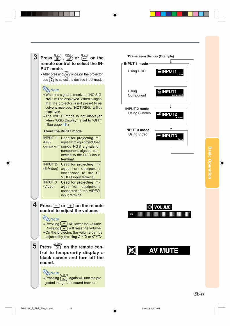
3 Press , or on theremote control to select the IN-PUT mode.• After pressing once on the projector,
use to select the desired input mode.
Note• When no signal is received, “NO SIG-
NAL” will be displayed. When a signalthat the projector is not preset to re-ceive is received, “NOT REG.” will bedisplayed.
• The INPUT mode is not displayedwhen “OSD Display” is set to “OFF”.(See page 45.)
About the INPUT mode
4 Press or on the remotecontrol to adjust the volume.
Note• Pressing will lower the volume.
Pressing will raise the volume.• On the projector, the volume can be
adjusted by pressing or .
5 Press on the remote con-trol to temporarily display ablack screen and turn off thesound.
Note• Pressing again will turn the pro-
jected image and sound back on.
"On-screen Display (Example)
Using RGB
UsingComponent
INPUT 1 mode
INPUT 3 mode Using Video
INPUT 2 mode Using S-Video
Used for projecting im-ages from equipment thatsends RGB signals orcomponent signals con-nected to the RGB inputterminal.
Used for projecting im-ages from equipmentconnected to the S-VIDEO input terminal.
Used for projecting im-ages from equipmentconnected to the VIDEOinput terminal.
INPUT 1(RGB/Component)
INPUT 2(S-Video)
INPUT 3(Video)
PG-A20X_E_PDF_P26_31.p65 03.4.23, 9:57 AM27

-28
Image Projection
Selecting the On-screenDisplay LanguageThe on-screen display language of the projector can beset to English, German, Spanish, Dutch, French, Ital-ian, Swedish, Portuguese, Chinese, Korean or Japanese.
1 Press on the remote control.• The “Picture” menu will be displayed.
2 Press \ or | to select the “Lan-guage” menu icon.• The “Language” menu will be displayed.
3 Press ' or " to select the desiredlanguage, and then press
.
4 Press .• The desired language will be set as the
on-screen display.
Turning the Power off
1 Press STANDBY on the projector orSTANDBY
on the remote control, thenpress that button again while theconfirmation message is dis-played, to put the projector intothe standby mode.
Note
• If you accidentally pressed STANDBY orSTANDBY
and do not want to put the projectorinto the standby mode, wait until the con-firmation message disappears.
• The projector cannot be operatedwhile a message “Shutting Down.Please Wait.” is displayed.
2 Unplug the power cord from the ACoutlet after the cooling fan stops.
Info
• Do not unplug the power cord during pro-jection or cooling fan operation. This cancause damage due to rise in internal tem-perature, as the cooling fan also stops.
', ", \, |buttons
ENTERbutton
STANDBYbutton
MENU button
“Language” menu icon
PG-A20X_E_PDF_P26_31.p65 03.4.23, 9:57 AM28
Basic O
peratio
n
-29
Keystone Correction (Correcting Trapezoidal Distortion)
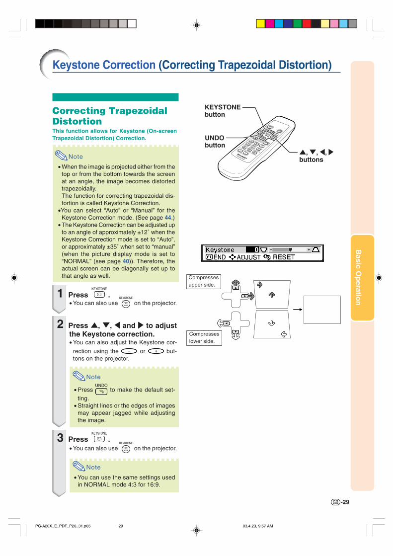
Correcting TrapezoidalDistortionThis function allows for Keystone (On-screenTrapezoidal Distortion) Correction.
Note
• When the image is projected either from thetop or from the bottom towards the screenat an angle, the image becomes distortedtrapezoidally.The function for correcting trapezoidal dis-tortion is called Keystone Correction.
•You can select “Auto” or “Manual” for theKeystone Correction mode. (See page 44.)
• The Keystone Correction can be adjusted upto an angle of approximately ±12˚ when theKeystone Correction mode is set to “Auto”,or approximately ±35˚ when set to “manual”(when the picture display mode is set to“NORMAL” (see page 40)). Therefore, theactual screen can be diagonally set up tothat angle as well.
1 Press .• You can also use on the projector.
2 Press ', ", \ and | to adjustthe Keystone correction.• You can also adjust the Keystone cor-
rection using the or but-tons on the projector.
Note
• Press to make the default set-ting.
• Straight lines or the edges of imagesmay appear jagged while adjustingthe image.
3 Press .• You can also use on the projector.
Note
• You can use the same settings usedin NORMAL mode 4:3 for 16:9.
Compressesupper side.
Compresseslower side.
', ", \, |buttons
UNDObutton
KEYSTONEbutton
PG-A20X_E_PDF_P26_31.p65 03.4.23, 9:57 AM29

-30
Menu Items
This list shows the items that can be set in the projector.
INPUT 1 Mode
Note
• In the “Picture” menu of INPUT 1, “Color”, “Tint” and “Sharp” are only displayed when “Signal Type” is setto “Component” or set to “Auto” and the input signal is recognized as a component signal.
• In the “Picture” menu of INPUT 1, “sRGB” is only displayed when “Signal Type” is set to “RGB” or set to“Auto” and the input signal is recognized as an RGB signal.
+30−30
+30−30
+30−30
+30−30
+30−30
+30−30
+30−30
Main menu Sub menu Main menu Sub menu
Contrast
Bright
Color
Tint
Sharp
Red
Blue
Reset
sRGB [ON/OFF]
CLR Temp
Gamma
Signal Type
Memory
AutoRGBComponent
5500 K6500 K7500 K8500 K9300 K10500 K
StandardPresentationCinemaGame
Memory 1Memory OFF
Memory 5
Picture
Page 36
+15−15
+30−30
+30−30
+30−30
Fine Sync
Page 38Clock
Phase
H-Pos
V-Pos
Reset
Special Modes
Auto Sync
Signal Info
Options
Page 44
OSD Display [ON/OFF]
Keystone
Background
Eco Mode [Eco/Standard]
SharpBlueNone
AutoManual
Auto Power Off [ON/OFF]
Menu Position
Password
Anti-Theft
CenterUpper RightLower RightUpper LeftLower Left
Old PasswordNew PasswordReconfirm
Menu Color[Opaque/Translucent]
Old CodeNew CodeReconfirm
Language
Page 28
Page 50
Lamp Timer (Life)
PRJ Mode FrontCeiling+FrontRearCeiling+Rear
EnglishDeutschEspañolNederlandsFrançaisItalianoSvenskaPortuguês
PG-A20X_E_PDF_P26_31.p65 03.4.23, 9:57 AM30

Basic O
peratio
n
-31
INPUT 2 / 3 Mode
Main menu
+30−30
+30−30
+30−30
+30−30
+30−30
+30−30
+30−30
Main menu Sub menu
Contrast
Bright
Color
Tint
Sharp
Red
Blue
Reset
CLR Temp
Gamma
Memory
5500 K6500 K7500 K8500 K9300 K10500 K
StandardPresentationCinemaGame
Memory 1Memory OFF
AutoManual
Memory 5
Picture
Page 36
Options
Page 44
OSD Display [ON/OFF]
Keystone
Background
Eco Mode [Eco/Standard]
SharpBlueNone
Auto Power Off [ON/OFF]
Menu Position
Password
Anti-Theft
CenterUpper RightLower RightUpper LeftLower Left
Old PasswordNew PasswordReconfirm
Menu Color[Opaque/Translucent]
Old CodeNew CodeReconfirm
Lamp Timer (Life)
Video System
Language
Page 28
Page 50
PRJ Mode FrontCeiling+Front RearCeiling+Rear
AutoPALNTSC3.58SECAMNTSC4.43PAL-MPAL-NPAL-60
EnglishDeutschEspañolNederlandsFrançaisItalianoSvenskaPortuguês
PG-A20X_E_PDF_P26_31.p65 03.4.23, 9:57 AM31
-32
The menu screens allow you to adjust the image and various projector settings.You can operate the menus from the remote control using the following procedure.
Using the Menu Screen
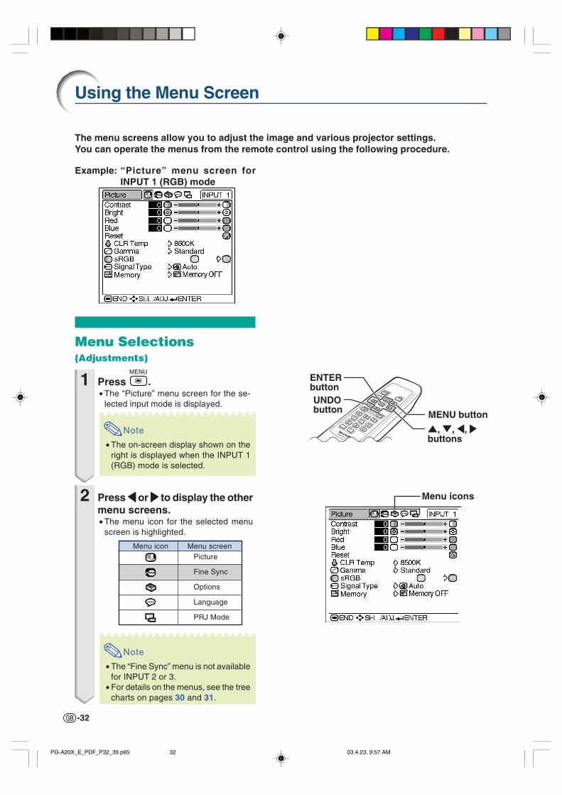
Example: “Picture” menu screen forINPUT 1 (RGB) mode
Menu Selections(Adjustments)
1 Press .• The “Picture” menu screen for the se-
lected input mode is displayed.
Note
• The on-screen display shown on theright is displayed when the INPUT 1(RGB) mode is selected.
2 Press \\\\\ or ||||| to display the othermenu screens.• The menu icon for the selected menu
screen is highlighted.
Note
• The “Fine Sync” menu is not availablefor INPUT 2 or 3.
• For details on the menus, see the treecharts on pages 30 and 31.
Menu icons
Menu icon Menu screenPicture
Fine Sync
Options
Language
PRJ Mode
', ", \, |buttons
UNDObutton
ENTERbutton
MENU button
PG-A20X_E_PDF_P32_39.p65 03.4.23, 9:57 AM32

Basic O
peratio
n
-33
3 Press ''''' or """"" to select the itemyou want to adjust.• The selected item is highlighted.
Note
• To display a single adjustment item,
press after selecting the item.
Only the selected adjustment item willbe displayed.Then if you press ' or ", the follow-ing item (“Red” after “Bright”) will bedisplayed.
• Press to return to the previous
screen.
4 Press \\\\\ or ||||| to adjust the itemselected.• The adjustment is stored.
5 Press .• The menu screen will disappear.
PG-A20X_E_PDF_P32_39.p65 03.4.23, 9:57 AM33

-34
Menu Selections(Settings)
1 Press .• The “Picture” menu screen for the se-
lected input mode is displayed.
Note
• The on-screen display shown on theright is displayed when INPUT 1 (RGB)mode is selected.
2 Press \\\\\ or ||||| to display the othermenu screens.• The menu icon for the selected menu
screen is highlighted.
Note
• The “Fine Sync” menu is not availablefor INPUT 2 or 3.
• For details on the menus, see the treecharts on pages 30 and 31.
Using the Menu Screen
Menu icon Menu screenPicture
Fine Sync
Options
Language
PRJ Mode
Menu icons
', ", \, |buttons
UNDObutton
ENTERbutton
MENU button
PG-A20X_E_PDF_P32_39.p65 03.4.23, 9:57 AM34
Basic O
peratio
n
-35
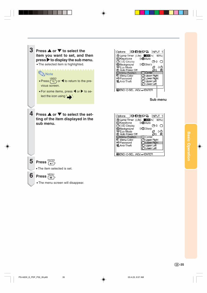
Sub menu
3 Press ''''' or """"" to select theitem you want to set, and thenpress ||||| to display the sub menu.• The selected item is highlighted.
Note
• Press or \ to return to the pre-
vious screen.
• For some items, press \ or | to se-
lect the icon using “ ”.
4 Press ''''' or """"" to select the set-ting of the item displayed in thesub menu.
5 Press .
• The item selected is set.
6 Press .
• The menu screen will disappear.
PG-A20X_E_PDF_P32_39.p65 03.4.23, 9:57 AM35
-36
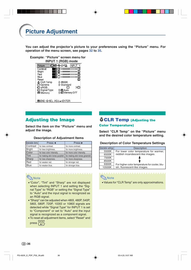
You can adjust the projector’s picture to your preferences using the “Picture” menu. Foroperation of the menu screen, see pages 32 to 35.
CLR Temp (Adjusting the
Color Temperature)
Select “CLR Temp” on the “Picture” menuand the desired color temperature setting.
Description of Color Temperature Settings
Adjusting the ImageSelect the item on the “Picture” menu andadjust the image.
Description of Adjustment Items
Note• “Color”, “Tint” and “Sharp” are not displayed
when selecting INPUT 1 and setting the “Sig-nal Type” to “RGB” or setting the “Signal Type”to “Auto” and the input signal is recognized asan RGB signal.
• “Sharp” can be adjusted when 480I, 480P, 540P,580I, 580P, 720P, 1035I or 1080I signals aredetected while “Signal Type” for INPUT 1 is setto “Component” or set to “Auto” and the inputsignal is recognized as a component signal.
• To reset all adjustment items, select “Reset” and
press .
Picture Adjustment
Selectable settings5500K6500K7500K8500K9300K
10500K
DescriptionFor lower color temperature for warmer,reddish incandescent-like images.
For higher color temperature for cooler, blu-ish, fluorescent-like images.
Selectable items Press \ Press |ContrastBrightColorTintSharpRedBlue
for less contrast.for less brightness.for less color intensity.for making skin tones purplish.for less sharpness.for weaker red.for weaker blue.
for more contrast.for more brightness.for more color intensity.for making skin tones greenish.for more sharpness.for stronger red.for stronger blue.
Example: “Picture” screen menu forINPUT 1 (RGB) mode
Note• Values for “CLR Temp” are only approximations.
PG-A20X_E_PDF_P32_39.p65 03.4.23, 9:57 AM36

Basic O
peratio
n
-37
Selectable settingsStandardPresentation
Cinema
Game
DescriptionFor standard imageBrightens darker portions of image formore enhanced presentations.Gives greater depth to darker portionsof image for a more exciting theaterexperience.For natural color gradation for playinga game, etc.
Gamma (Gamma Correction)Gamma is an image quality enhancement functionthat offers a richer image by brightening the darkerportions of the image without altering the bright-ness of the brighter portions.When you are displaying images with frequent darkscenes, such as a film or concert, or when you aredisplaying images in a bright room, this featuremakes the dark scenes easier to see and gives theimpression of greater depth in the image.
Select “Gamma” on the “Picture” menu andthe desired gamma mode.
Description of Gamma Modes
Note
• Gamma is not available for INPUT 1 when“sRGB” on the “Picture” menu is set to “ON”.
sRGB (sRGB Setting)
Select “sRGB” on the “Picture” menu and setit to “ (ON)” when you want to displaythe image in a natural tint based on an origi-nal image.
Note• When “sRGB” is set to “ON”;
• Gamma is not available.• “Red”, “Blue” or “CLR Temp” on the “Picture”
menu cannot be adjusted.• For additional information about the sRGB func-
tion, visit “http://www.srgb.com/”.
Info• When “sRGB” is set to “ON”, the projected im-
age may become dark, but this does not indi-cate a malfunction.
Signal Type (Signal Type Setting)The signal type setting is preset to “Auto”;however, in rare cases a clear picture may not bedisplayed. In that case, select “RGB” or“Component” in accordance with the input signal.
Select “Signal Type” on the “Picture” menuand set it to “Auto”, “RGB” or “Component”for INPUT 1.
Memory (Storing and Selectingthe Adjustment Settings)
Use this function to store the adjustment settingson the “Picture” menu. No matter which input modeor signal type is selected, you can select and applythe settings you have stored in a memory location.
Select “Memory” on the “Picture” menu andthe memory location where you want to storethe settings. Then adjust the setting itemson the “Picture” menu.
If you want to apply the stored settings onthe “Picture” menu, select “Memory” on the“Picture” menu and the memory locationwhere you have stored the settings.
Note
• You can change the stored settings after se-lecting the memory location for those settings.
DescriptionInput signals are automaticallyrecognized as RGB or Component.Set when RGB signals are received.Set when Component signals arereceived.
Selectable settings Auto
RGB Component
Description
Settings of all items on the “Picture”menu can be stored in memory location.The stored settings can be selected inany input mode.
Besides “Memory 1” to “Memory 5”, othersettings on the “Picture” menu can bestored for each input mode. The settingsstored in “Memory OFF” cannot be appliedwhen another input mode is selected.
Memory 1 Memory 2 Memory 3 Memory 4 Memory 5
Memory OFF
Selectablesettings
Description of Memory Positions
Description of Signal Type Settings
PG-A20X_E_PDF_P32_39.p65 03.4.23, 9:57 AM37

-38
Using the “Fine Sync” menu, you can adjust the computer image, match the computer dis-play mode, and check the input signal. For operation of the menu screen, see pages 32 to 35.
Example: “Fine Sync” menu screen forINPUT 1 mode
Adjusting the ComputerImageWhen “Auto Sync” is set to OFF or when verticalstripes or flickering occur in portions of the screeneven if “Auto Sync” is set to ON, adjust “Clock”,“Phase”, “H-Pos” or “V-Pos” to obtain the best com-puter image.
Select the item on the “Fine Sync” menuand adjust the computer image.
Description of Adjustment Items
Note• You can automatically adjust the computer im-
age by setting “Auto Sync” on the “Fine Sync”menu or pressing the AUTO SYNC button. Seenext page for details.
• To reset all adjustment items, select “Reset” and
press .
Computer Image Adjustment
Special Modes (Special
Mode Settings)Ordinarily, the type of input signal is detected andthe correct resolution mode is automatically selected.However, for some signals, the optimal resolutionmode in “Special Modes” on the “Fine Sync” menumay need to be selected to match the computer dis-play mode.
Select “Special Modes” on the “Fine Sync”menu and the appropriate resolution.
Note
• Avoid displaying computer patterns which repeatevery other line (horizontal stripes).(Flickering may occur, making the image hard tosee.)
• When a DVD player or Digital Video is connected,select 480P as the input signal.
• See “Signal Info (Checking the Input Signal)” onthe next page for information on the currently se-lected input signal.
Selectable itemsClockPhase
H-Pos
V-Pos
Use \ and | toadjust vertical noise.adjust horizontal noise (similar to trackingon your VCR).center the on-screen image by moving it tothe left or right.center the on-screen image by moving it upor down.
PG-A20X_E_PDF_P32_39.p65 03.4.23, 9:57 AM38
Basic O
peratio
n
-39
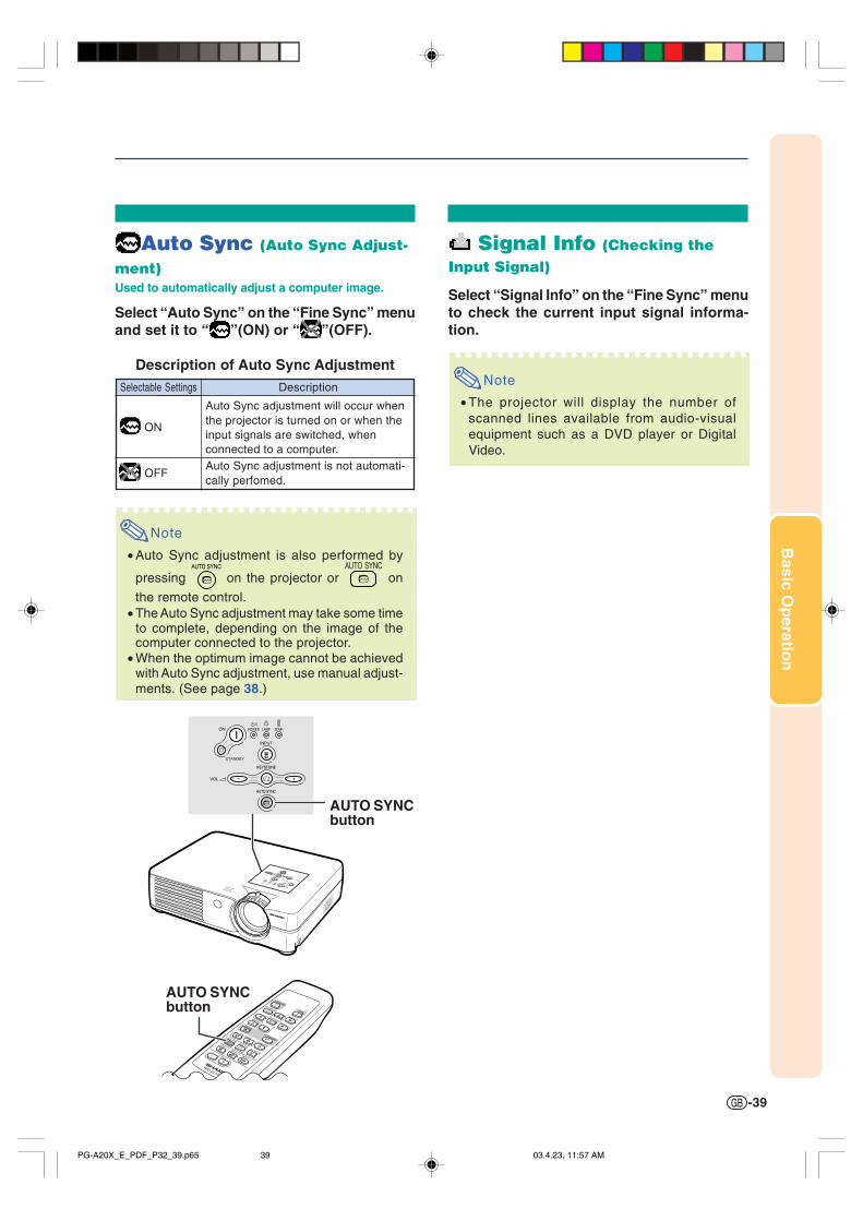
Signal Info (Checking theInput Signal)
Select “Signal Info” on the “Fine Sync” menuto check the current input signal informa-tion.
Note
• The projector will display the number ofscanned lines available from audio-visualequipment such as a DVD player or DigitalVideo.
Auto Sync (Auto Sync Adjust-
ment)Used to automatically adjust a computer image.
Select “Auto Sync” on the “Fine Sync” menuand set it to “ ”(ON) or “ ”(OFF).
Description of Auto Sync AdjustmentSelectable Settings Description
Auto Sync adjustment will occur whenthe projector is turned on or when theinput signals are switched, whenconnected to a computer.Auto Sync adjustment is not automati-cally perfomed.
Note
• Auto Sync adjustment is also performed by
pressing on the projector or on
the remote control.• The Auto Sync adjustment may take some time
to complete, depending on the image of thecomputer connected to the projector.
• When the optimum image cannot be achievedwith Auto Sync adjustment, use manual adjust-ments. (See page 38.)
ON
OFF
AUTO SYNCbutton
AUTO SYNCbutton
PG-A20X_E_PDF_P32_39.p65 03.4.23, 11:57 AM39

-40
Picture Display Mode
Switching the Picture Dis-play Mode
Press .
• Pressing changes the display as shown on
pages 40 and 41.• To return to the standard image, press while
“RESIZE” is displayed on the screen.
This function allows you to modify or customize the picture display mode to enhance theinput image. Depending on the input signal, you can choose “NORMAL”, “DOT BY DOT”,“BORDER” or “STRETCH” image.
COMPUTER
STRETCHProjects 16:9 image
evenly over entire screen(top/bottom blank bands).
Output screen imageInput Signal
Image type
NORMALProjects a full screen
image while maintaining the aspect ratio.
DOT BY DOTProjects the original
resolution signalof the image.
BORDERProjects 4:3 image fully
in STRETCH (the followingcolumn) image.
4:3 aspect ratio
4:3 aspect ratio
4:3 aspect ratio
5:4 aspect ratio
16:9 aspect ratio
: Cutout area on which images cannot be projected.
: Area where the signals are off screen.* Mode for projecting an image with the original aspect ratio without cutting any portions.
* * *
* *
* *
* *
*
Computer
Resolutionlower than
XGA
XGA
Resolutionhigher than
XGA
1280 × 720
SXGA (1280 × 1024)
4:3 aspect ratio
Other aspect ratios
SVGA (800 × 600)
XGA (1024 × 768)
SXGA (1280 × 960)
SXGA+ (1400 × 1050)
SXGA (1280 × 1024)
1280 × 720
1024 × 768
960 × 768
—
800 × 600
—
1280 × 960
1400 × 1050
1280 × 1024
—
768 × 576
720 × 576
—
1024 × 576
960 × 576
1024 × 576
NORMAL DOT BY DOT BORDER STRETCH
RESIZEbutton
UNDObutton
PG-A20X_E_PDF_P40_50.p65 03.4.23, 9:58 AM40

-41
Easy to
Use F
un
ction
s
VIDEO
• “STRETCH” is fixed when 540P, 720P or 1080I signals are entered.
4:3 aspect ratio
Letter box
Squeezed 16:9 image
Squeezed 4:3 image
16:9 aspect ratio
16:9 aspect ratio(4:3 aspect ratio in
16:9 screen)
Output screen image
Input Signal
Image typeDVD / Video
480I, 480P,NTSC, PAL, SECAM
540P, 720P,1080I (16:9)
: Cutout area on which images cannot be projected.
: Area on which the image is not included in the original signals.
* Mode for projecting an image with the original aspect ratio without cutting any portions.
* *
*
*
*
*
*
*
BORDERProjects 4:3 image fully in STRETCH (the following
column) image.
STRETCHProjects 16:9 image evenly
over entire screen (top/bottom black bands).
NORMALProjects a full screen image.
480I, 480P,
NTSC, PAL, SECAM
540P, 720P, 1080I
4:3 aspect ratio.
Letter box, squeeze
16:9 aspect ratio
1024 × 768
—
768 × 576
—1024 × 576
NORMAL BORDER STRETCH
PG-A20X_E_PDF_P40_50.p65 03.4.23, 9:58 AM41

-42
×1 ×4 ×9 ×16 ×36 ×64×2 ×3
You can instantly freeze a moving image and enlarge a specific portion of an image with theremote control. Using these functions, you can explain the image to the audience more ef-fectively.
Still and Zoom Image
Freezing a MovingImage
1 Press .• The projected image is frozen.
2 Press again to return to themoving image from the currentlyconnected device.
Displaying an EnlargedPortion of an Image
1 Press .
• Pressing or enlarges or reducesthe projected image.
Note
• You can change the location of the en-larged image using ', ", \ and |.
2 Press to cancel the operation.• The magnification then returns to ×1.
Note
In the following cases, the image will re-turn to the normal size (×1).• When switching the INPUT mode.
• When has been pressed.
• When the input signal is changed.• When the input signal resolution and re-
fresh rate (vertical frequency) change.
FREEZEbutton
', ", \, |buttons
UNDObutton
ENLARGE(Enlarge/Reduce)buttons
PG-A20X_E_PDF_P40_50.p65 03.4.23, 9:58 AM42

-43
Easy to
Use F
un
ction
s
Keylock Function
Locking the Operation But-tons
Hold down on the projector forabout 3 seconds while the projector isbeing turned on.
Note
• The keylock function does not affect the opera-tion with the remote control buttons.
• You cannot use the keylock function while theprojector is warming up or shutting down.
Use this function to lock the operation buttons on the projector.
Taking the Keylock off
Hold down on the projector for
about 3 seconds.
Note
• The keylock function does not affect the opera-tion with the remote control buttons.
• You cannot use the keylock function while theprojector is warming up or shutting down.
ON button
PG-A20X_E_PDF_P40_50.p65 03.4.23, 9:58 AM43

-44
You can use the “Options” menu to enhance the usage for the projector. For operation of themenu screen, see pages 32 to 35.
Example: “Options” menu screen forINPUT 2 (S-Video) mode
Lamp Timer (Life) (Check-ing the Lamp Life Status)You can confirm the cumulative lamp usage timeand the remaining lamp life (percentage).
Display the “Options” menu to check thelamp life status.
Description of Lamp Life
Note
• It is recommended that the lamp be changedwhen the remaining lamp life becomes 5%.For lamp replacement, contact your nearestSharp Authorized Projector Dealer or ServiceCenter.
• The table above indicates rough estimates in thecase of using only in each mode shown. Remain-ing lamp life changes within the range of the val-ues shown depending on the frequency at which“Eco Mode” is switched to “ ” (Eco mode) and“ ” (Standard mode) (see page 45).
Using the “Options” Menu
Remaining lamp life100% 5%
about4,500 hours 225 hours
about3,000 hours 150 hours
Lamp usage condition
Used with only “ ”(Eco mode) in “EcoMode”Used with only “ ”(Standard mode) in“Eco Mode”
Keystone (Setting the Key-
stone Correction Mode)
Select “Keystone” on the “Options” menuand the desired mode for the KeystoneCorrection.
Description of Keystone Correction Mode
Note
• If you want to adjust the Keystone Correctionmanually, see page 29.
• The Keystone Correction can be adjusted up toan angle of approximately ±12˚ when the Key-stone Correction mode is set to “Auto”, or ap-proximately ±35˚ when set to “manual” (when thepicture display mode is set to “NORMAL” (seepage 40)).
Selectable settings Auto
Manual
DescriptionKeystone Correction is automaticallyperformed.Keystone Correction can be adjustedmanually.
Auto Manual
PG-A20X_E_PDF_P40_50.p65 03.4.23, 9:58 AM44

-45
Easy to
Use F
un
ction
s
Video System (Setting theVideo System)
The video input system mode is preset to “Auto”;however, a clear picture from the connected audio-visual equipment may not be received, dependingon the video signal difference. In that case, switchthe video signal.
Select “Video System” on the “Options” menuand the appropriate video system.
Note
• The video signal can only be set in INPUT 2 orINPUT 3 mode.
• In “Auto”, images are displayed in PAL even ifPAL-N or PAL-M input signals are received.
Background (Selecting aStartup and Background Image)
Select “Background” on the “Options” menuand the image displayed upon theprojector’s startup and when no signal isbeing sent to the projector.
Description of Background Images
Note
• If the input signal has interference, the screenwill be displayed during interference.
Eco Mode (Setting the EcoMode)
Select “ ” (Eco Mode) or “ ” (Standard
Mode) in “Eco Mode” on the “Options” menu.
Description of Eco Mode
Note
• Although lamp life and noise are improved when
“Eco Mode” is set to “ ” (Eco mode), bright-
ness decreases by 20%.
• “Eco Mode” mode is factory preset to “ ” (Stan-
dard mode).
Sharp Blue None
Selectable settings
PAL
SECAM
NTSC4.43
NTSC3.58
DescriptionWhen connected to PAL videoequipment.When connected to SECAM videoequipment.When reproducing NTSC signals inPAL video equipment.When connected to NTSC videoequipment.
Selectable settings Sharp
Blue
None
DescriptionSHARP default image
Blue screen
Black screen
Brightness
80%
100%
Selectable settings
(Eco mode)
(Standard mode)
Power consumption(When using AC 110V)
190 W
240 W
Lamp life
4,500 hours
3,000 hours
OSD Display (Setting On-
screen Display)This function allows you to turn the on-screen mes-sages on or off.
Select “ ” (ON) or “ ” (OFF) in “OSDDisplay” on the “Options” menu.
Description of “OSD Display” Settings
*Displayed when the STANDBY button is pressed.
Description of Video Systems
DescriptionAll On-screen Displays are displayed.INPUT/VOLUME/AV MUTE/FREEZE/AUTO SYNC/ENLARGE/ “An invalidbutton has been pressed.” / *“All buttonson Projector are locked.” are not displayed.
Selectable settings ON OFF
PG-A20X_E_PDF_P40_50.p65 03.4.23, 9:58 AM45

-46
Auto Power Off (Auto
Power Off Function)When no input signal is detected for more than 15minutes, the projector will automatically enter thestandby mode if set to “ON”.The Auto Power Off function will be disabled if ithas been set to “OFF”.
Select “ ” (ON) or “ ” (OFF) in “Auto
Power Off” on the “Options” menu.
Note
• When the Auto Power Off function is set to “ON”,5 minutes before the projector enters thestandby mode, the message “Enter STANDBYmode in X min.” will appear on the screen toindicate the remaining minutes before power off.
Menu Position (Selecting
the Menu Screen Position)
Select “Menu Position” on the “Options”menu and the desired position for the menuscreen.
Description of Menu Positions
Menu Color (Selecting theMenu Color)
Select “ ” (Opaque) or “ ” (Translucent)
in “Menu Color” on the “Options” menu.
Description of Menu Colors
Using the “Options” Menu
Selectable settings Center Upper Right Lower Right Upper Left Lower Left
DescriptionDisplayed on the center of the image.Displayed on the upper right of the image.Displayed on the lower right of the image.Displayed on the upper left of the image.Displayed on the lower left of the image.
Example: “Options” menu screen forINPUT 2 (S-Video) mode
Selectable settings Opaque Translucent
DescriptionThe menu is displayed opaquely.The menu is displayed translucently.The part of the menu on the imagebecomes transparent.
PG-A20X_E_PDF_P40_50.p65 03.4.23, 9:58 AM46
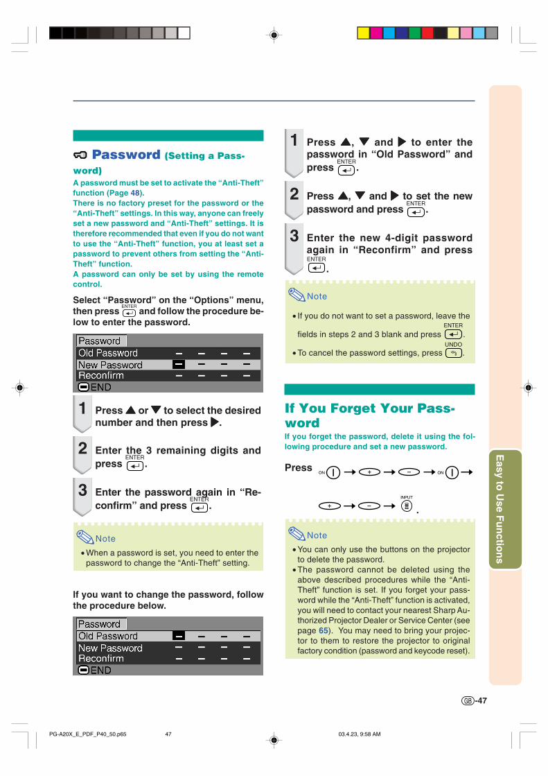
-47
Easy to
Use F
un
ction
s
Password (Setting a Pass-
word)A password must be set to activate the “Anti-Theft”function (Page 48).There is no factory preset for the password or the“Anti-Theft” settings. In this way, anyone can freelyset a new password and “Anti-Theft” settings. It istherefore recommended that even if you do not wantto use the “Anti-Theft” function, you at least set apassword to prevent others from setting the “Anti-Theft” function.A password can only be set by using the remotecontrol.
Select “Password” on the “Options” menu,then press and follow the procedure be-low to enter the password.
1 Press ''''' or """"" to select the desirednumber and then press |||||.
2 Enter the 3 remaining digits andpress .
3 Enter the password again in “Re-confirm” and press .
Note
• When a password is set, you need to enter thepassword to change the “Anti-Theft” setting.
If you want to change the password, followthe procedure below.
1 Press ''''', """"" and ||||| to enter thepassword in “Old Password” andpress .
2 Press ''''', """"" and ||||| to set the newpassword and press .
3 Enter the new 4-digit passwordagain in “Reconfirm” and press
.
Note
• If you do not want to set a password, leave the
fields in steps 2 and 3 blank and press .
• To cancel the password settings, press .
If You Forget Your Pass-wordIf you forget the password, delete it using the fol-lowing procedure and set a new password.
Press
Note
• You can only use the buttons on the projectorto delete the password.
• The password cannot be deleted using theabove described procedures while the “Anti-Theft” function is set. If you forget your pass-word while the “Anti-Theft” function is activated,you will need to contact your nearest Sharp Au-thorized Projector Dealer or Service Center (seepage 65). You may need to bring your projec-tor to them to restore the projector to originalfactory condition (password and keycode reset).
PG-A20X_E_PDF_P40_50.p65 03.4.23, 9:58 AM47

-48
Anti-Theft (Setting the Anti-Theft)The anti-theft function prevents unauthorized useof the projector. You can choose to use this func-tion or not. If you do not want to use this function,just do not enter the keycode. Once the anti-theftfunction is activated, users will need to enter thecorrect keycode each time the projector is turnedon. Failure to enter the correct keycode will causeimages to not be projected. The following proce-dures explain how to use this function.
Select “Anti-Theft” on the “Options” menu,then press and follow the procedure be-low to enter the keycode.
Note
• “Anti-Theft” cannot be selected unless“Password” is set. (See page 47.)
• When “Anti-Theft” is selected, the password in-put box will appear. Enter the keycode after theright password is entered.
Info
• Once the function is activated, you must remem-ber the correct keycode. We suggest you recordthe keycode in a safe place where only authorizedusers have access. If you lose or forget yourkeycode, you will need to contact your nearestSharp Authorized Projector Dealer or Service Cen-ter (see page 65). You may need to bring yourprojector to them to restore the projector to originalfactory condition (password and keycode reset).
Using the “Options” Menu
1 Press any button you like on the re-mote control or projector to set thefirst digit in “New Code”.
Note
• The following buttons on the remote con-trol and projector cannot be set askeycodes:• ON button• STANDBY button• ENTER button• UNDO button• MENU button• FORWARD button• BACK button
2 Enter the remaining 3 digits bypressing any buttons you like.
3 Enter the same keycode once morein “Reconfirm”.
Info
When “Anti-Theft” is set, the keycode in-putting box appears after the power isturned on. When it appears, enter the rightkeycode.• Press the buttons on the remote control if the
buttons on the remote control are used for set-ting the keycode. In the same manner, pressthe buttons on the projector if the buttons onthe projector are used for setting the keycode.
Example: “Options” menu screen forINPUT 2 (S-Video) mode
PG-A20X_E_PDF_P40_50.p65 03.4.23, 9:58 AM48

-49
Easy to
Use F
un
ction
s
If you want to change the keycode, followthe procedure below.
Note
• When “Anti-Theft” is selected, the password in-put box will appear. After the password has beenentered, you can change the keycode.
1 Press the buttons on the remotecontrol or the projector to enter thepreset 4-digit keycode in “OldCode”.
2 Press any button you like on the re-mote control or the projector to en-ter the new keycode.
3 Enter the same 4-digit keycode in“Reconfirm”.
Note
• If you do not want to set a keycode, leave thekeycode field blank in steps 2 and 3 and press
.
PG-A20X_E_PDF_P40_50.p65 03.4.23, 9:58 AM49
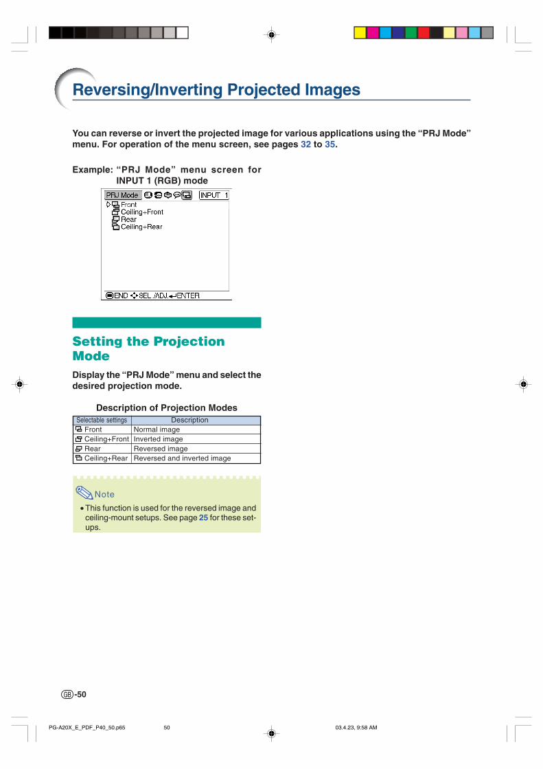
-50
Reversing/Inverting Projected Images
You can reverse or invert the projected image for various applications using the “PRJ Mode”menu. For operation of the menu screen, see pages 32 to 35.
Example: “PRJ Mode” menu screen forINPUT 1 (RGB) mode
Setting the ProjectionModeDisplay the “PRJ Mode” menu and select thedesired projection mode.
Description of Projection Modes
Note
• This function is used for the reversed image andceiling-mount setups. See page 25 for these set-ups.
Selectable settings Front Ceiling+Front Rear Ceiling+Rear
DescriptionNormal imageInverted imageReversed imageReversed and inverted image
PG-A20X_E_PDF_P40_50.p65 03.4.23, 9:58 AM50
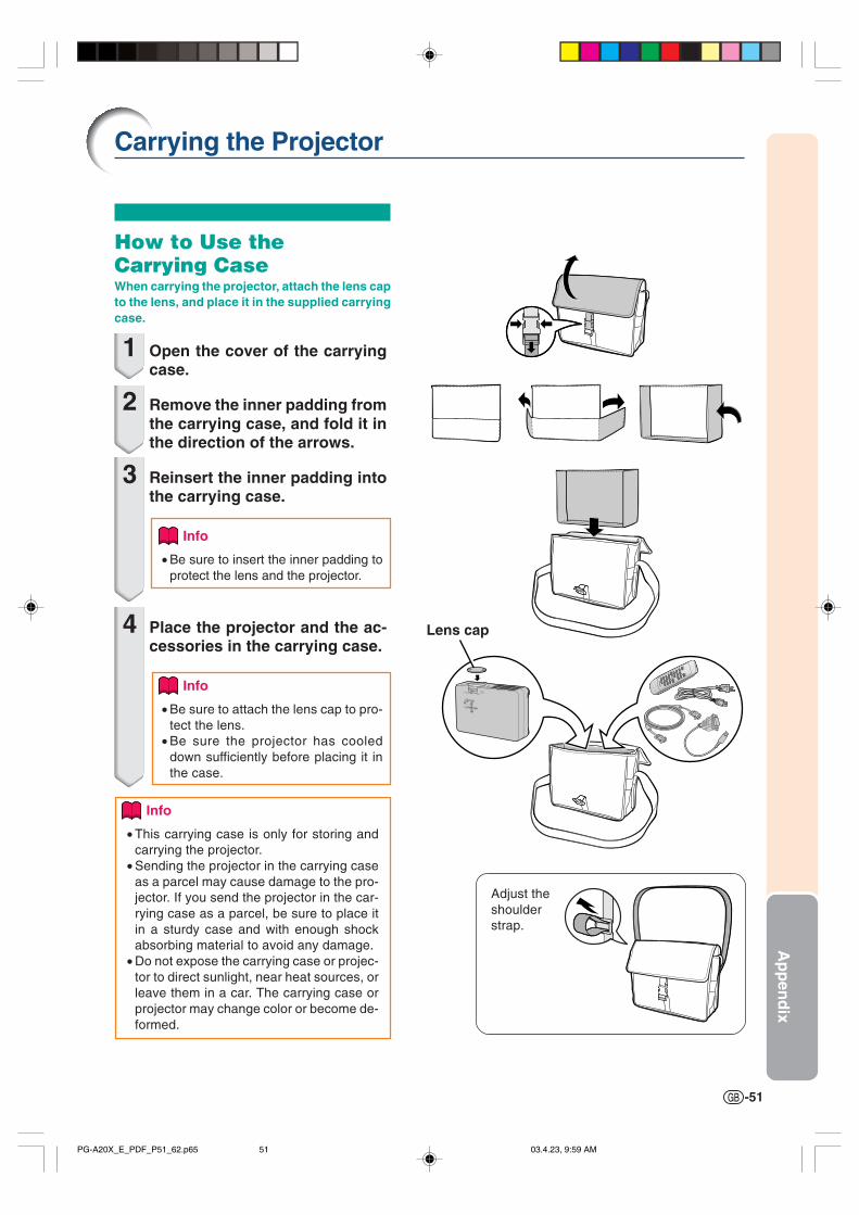
-51
Ap
pen
dix
Carrying the Projector
How to Use theCarrying CaseWhen carrying the projector, attach the lens capto the lens, and place it in the supplied carryingcase.
1 Open the cover of the carryingcase.
2 Remove the inner padding fromthe carrying case, and fold it inthe direction of the arrows.
3 Reinsert the inner padding intothe carrying case.
Info
• Be sure to insert the inner padding toprotect the lens and the projector.
4 Place the projector and the ac-cessories in the carrying case.
Info
• Be sure to attach the lens cap to pro-tect the lens.
• Be sure the projector has cooleddown sufficiently before placing it inthe case.
Info
• This carrying case is only for storing andcarrying the projector.
• Sending the projector in the carrying caseas a parcel may cause damage to the pro-jector. If you send the projector in the car-rying case as a parcel, be sure to place itin a sturdy case and with enough shockabsorbing material to avoid any damage.
• Do not expose the carrying case or projec-tor to direct sunlight, near heat sources, orleave them in a car. The carrying case orprojector may change color or become de-formed.
Adjust theshoulderstrap.
Lens cap
PG-A20X_E_PDF_P51_62.p65 03.4.23, 9:59 AM51
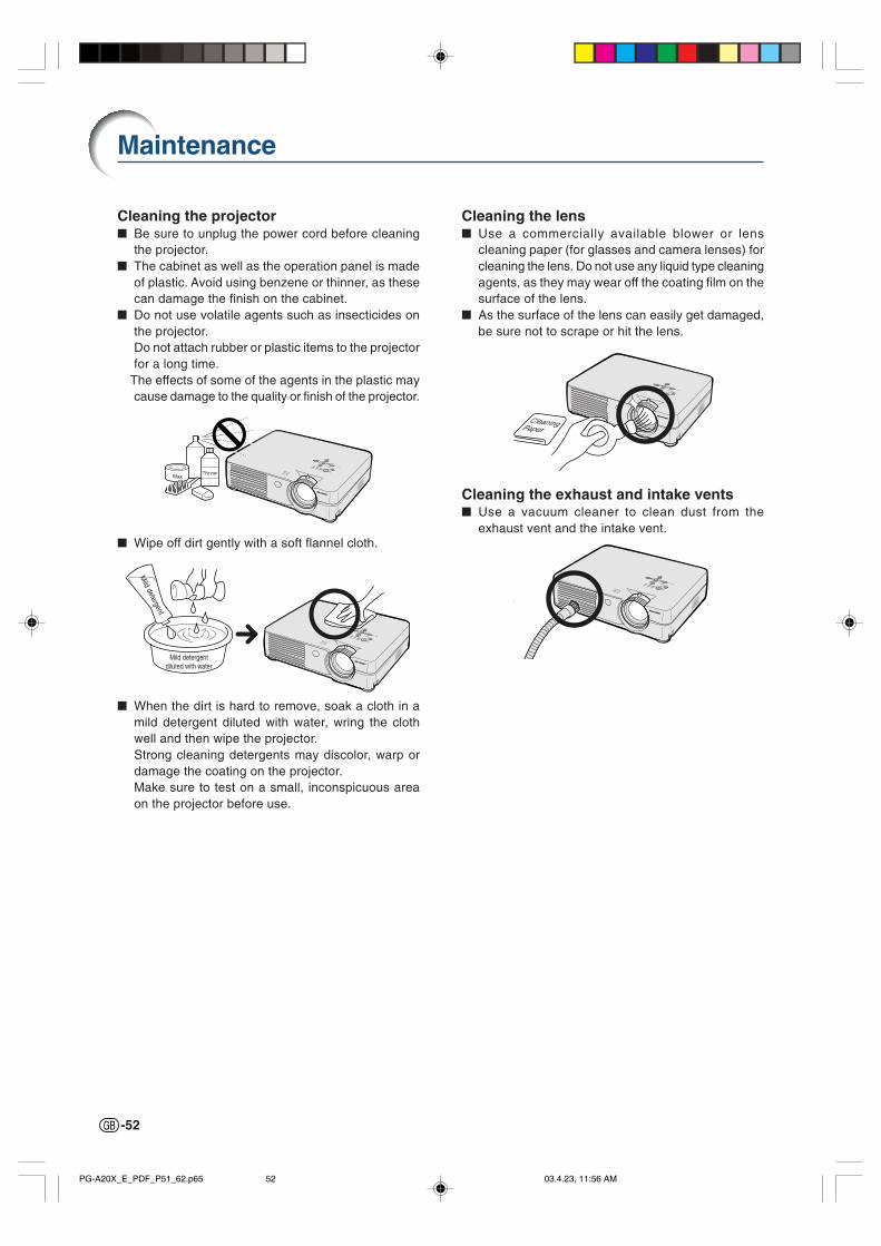
-52
Cleaning the lens Use a commercially available blower or lens
cleaning paper (for glasses and camera lenses) forcleaning the lens. Do not use any liquid type cleaningagents, as they may wear off the coating film on thesurface of the lens.
As the surface of the lens can easily get damaged,be sure not to scrape or hit the lens.
Cleaning the exhaust and intake vents Use a vacuum cleaner to clean dust from the
exhaust vent and the intake vent.
Cleaning the projector Be sure to unplug the power cord before cleaning
the projector. The cabinet as well as the operation panel is made
of plastic. Avoid using benzene or thinner, as thesecan damage the finish on the cabinet.
Do not use volatile agents such as insecticides onthe projector.Do not attach rubber or plastic items to the projectorfor a long time.
The effects of some of the agents in the plastic maycause damage to the quality or finish of the projector.
Wipe off dirt gently with a soft flannel cloth.
When the dirt is hard to remove, soak a cloth in amild detergent diluted with water, wring the clothwell and then wipe the projector.Strong cleaning detergents may discolor, warp ordamage the coating on the projector.Make sure to test on a small, inconspicuous areaon the projector before use.
Maintenance
WaxThinner
Mild detergentdiluted with water
Mild detergent
CleaningPaper
PG-A20X_E_PDF_P51_62.p65 03.4.23, 11:56 AM52

-53
Ap
pen
dix
1
2
3
Replacing the Air Filter
Tab
• This projector is equipped with air fil-ters to ensure the optimal operatingcondition of the projector.
• The air filters should be cleaned every100 hours of use. Clean the filters moreoften when the projector is used in adusty or smoky location.
• Ask your nearest Sharp Authorized Pro-jector Dealer or Service Center to ex-change the filter (PFILDA008WJZZ)when it is no longer possible to clean.
Cleaning and Replacingthe Air Filter
1 Press STANDBY on the projectoror
STANDBY on the remote control to
put the projector into thestandby mode.• Wait until the cooling fan stops.
2 Disconnect the power cord.• Unplug the power cord from the AC
socket.
3 Remove the filter/lamp unitcover.• Turn the projector over. Loosen the user
service screw (1) that secures the fil-ter/lamp unit cover. Pressing the tab(2), remove the filter/lamp unit cover(3).
4 Remove the air filter.• Pick the air filter up with your fingers and
lift it out of the filter/lamp unit cover.
STANDBY button
Air filter(not removable)
STANDBYbutton
User service screw
Air filter
Air filter(not removable)
""""" Bottom view
""""" Rear view
AC socket
PG-A20X_E_PDF_P51_62.p65 03.4.23, 9:59 AM53

-54
5 Clean the air filter.• Clean the dust off the air filter and cover
with a vacuum cleaner extension hose.
6 Replace the air filter.• Place the air filter underneath the tabs
on the filter/lamp unit cover.
7 Replace the filter/lamp unitcover.• Align the tab on the filter/lamp unit cover
(1) and place it while pressing the tab(2) to close it. Then tighten the userservice screw (3) to secure the filter/lamp unit cover.
Note
• Be sure the filter/lamp unit cover issecurely installed. The power will not turnon unless it is correctly installed.
• If dust or dirt has collected inside the rearand bottom air filters (not removable), cleanthe filter with a vacuum cleaner extensionhose.
1
2
3
Replacing the Air Filter
Tab
User service screw
PG-A20X_E_PDF_P51_62.p65 03.4.23, 9:59 AM54

-55
Ap
pen
dix
Maintenance Indicators
The warning lights on the projector indicate problems inside the projector. If a problem occurs, either the temperature warning indicator or the lamp indicator will illuminate
red, and the projector will enter the standby mode. After the projector has entered the standbymode, follow the procedures given below.
Temperature warning indicator
Lamp indicator
Power indicator
About the temperature warning indicatorIf the temperature inside the pro-jector increases, due to blockageof the air vents, or the setting lo-
cation, “ ” will illuminate in
the lower left corner of the picture.If the temperature keeps on rising,the lamp will turn off and the tem-perature warning indicator will blink,the cooling fan will run for a further90 seconds, and then the projectorwill enter the standby mode. After
“ ” appears, be sure to per-
form the following measures.
Maintenance indicatorCondition Problem Possible Solution
Temperaturewarningindicator
Normal Abnormal
Off Red on/Standby
The internaltemperature isabnormally high.
Abnormal
• Blocked air intake • Relocate the projector to an areawith proper ventilation.
• Cooling fan break-down
• Internal circuit failure• Clogged air intake
• Take the projector to your nearestSharp Authorized Projector Dealeror Service Center (see page 65)for repair.
Lampindicator
Red on/Standby
The lamp doesnot illuminate.
• Burnt-out lamp• Lamp circuit failure
• Carefully replace the lamp. (Seepage 58)
• Take the projector to your nearestSharp Authorized Projector Dealeror Service Center (see page 65)for repair.
• Please exercise care whenreplacing the lamp.
Red onTime to changethe lamp
• Remaining lamp lifebecomes 5% or less.
Powerindicator
The powerindicator blinksin red when theprojector is on.
• The filter/lamp unitcover is open.
• Securely install the cover.• If the power indicator blinks even
when the filter/lamp unit cover issecurely installed, contact yournearest Sharp Authorized Projec-tor Dealer or Service Center foradvice.
Green on/Red on Red blinks
Green onGreen
blinks whenthe lamp iswarming upor shutting
down.
About the lamp indicator
The lamp life becomes 0%, when usedfor approximately 4,500 hours with “EcoMode” or when used for approximately3,000 hours with “Standard Mode” (seepage 45).
When the remaining lamp life becomes
5% or less, “ ” (yellow) will be displayed
on the screen. When the percentage be-
comes 0%, “ ” will change to “ ” (red),
the lamp will automatically turn off andthen the projector will automatically en-ter the standby mode. At this time, thelamp indicator will illuminate in red.
If you try to turn on the projector a fourthtime without replacing the lamp, the pro-jector will not turn on.
PG-A20X_E_PDF_P51_62.p65 03.4.23, 9:59 AM55
-56
Info
• If the temperature warning indicator illuminates, and the projector enters the standby mode, follow the pos-sible solutions on the previous page and then wait until the projector has cooled down completely beforeplugging in the power cord and turning the power back on. (At least 5 minutes.)
• If the power is turned off for a brief moment due to power outage or some other cause while using theprojector, and the power supply recovers immediately after that, the lamp indicator will illuminate in red andthe lamp may not be lit. In this case, unplug the power cord from the AC outlet, replace the power cord in theAC outlet and then turn the power on again.
• If you want to clean the air vents during projector operation, be sure to put the projector into the standbymode. After the cooling fan has stopped, clean the vents.
• Do not unplug the power cord after the projector has entered the standby mode and while the cooling fan isrunning. The cooling fan runs for about 90 seconds.
Maintenance Indicators
PG-A20X_E_PDF_P51_62.p65 03.4.23, 9:59 AM56

-57
Ap
pen
dix
Lamp It is recommended that the lamp (sold separately) be replaced when the remaining lamp life be-
comes 5% or less, or when you notice a significant deterioration in the picture and color quality.The lamp life (percentage) can be checked with the on-screen display. See page 44.
For lamp replacement, please consult your nearest Sharp Authorized Projector Dealer or ServiceCenter.
IMPORTANT NOTE TO U.S. CUSTOMERS:The lamp included with this projector is backed by a 90-day parts and labor limited warranty. All serviceof this projector under warranty, including lamp replacement, must be obtained through a Sharp Autho-rized Projector Dealer or Service Center. For the name of the nearest Sharp Authorized Projector Dealeror Service Center, please call toll-free: 1-888-GO-SHARP (1-888-467-4277). U.S.A. ONLY
Caution Concerning the Lamp This projector utilizes a pressurized mercury lamp. A loud sound may indicate lamp failure. Lamp
failure can be attributed to numerous sources such as: excessive shock, improper cooling, surfacescratches or deterioration of the lamp due to a lapse of usage time. The period of time up to failurelargely varies depending on the individual lamp and/or the condition and the frequency of use. It isimportant to note that failure can often result in the bulb cracking.
When the lamp replacement indicator and on-screen display icon are illuminated, it is recommendedthat the lamp be replaced with a new one immediately, even if the lamp appears to be operatingnormally.
Should the lamp break, the glass particles may spread inside the lamp cage or gas contained in thelamp may be vented into the room from the exhaust vent. Because the gas in this lamp includesmercury, ventilate the room well if the lamp breaks and avoid all exposure to the released gas. Incase of exposure to the gas, consult a doctor as soon as possible.
Should the lamp break, there is also a possibility that glass particles may spread inside of theprojector. In such a case, it is recommended you contact your nearest Sharp Authorized ProjectorDealer or Service Center to remove the damaged lamp and assure safe operation.
Replacing the Lamp
Caution
• Do not remove the lamp unit immediately after operation of the projector. The lamp will be hot and touchingit can lead to burn or injury.
• Wait at least one hour after the power cord is disconnected to allow the surface of the lamp unit to fully coolbefore removing the lamp unit.
If the new lamp does not light after replacement, take your projector to the nearest Sharp Autho-rized Projector Dealer or Service Center for repair. Purchase a replacement lamp unit of type BQC-PGA20X//1 from your nearest Sharp Authorized Projector Dealer or Service Center. Then carefullychange the lamp by following the instructions described in this section. If you wish, you may havethe lamp replaced at your nearest Sharp Authorized Projector Dealer or Service Center.
Regarding the Lamp
PG-A20X_E_PDF_P51_62.p65 03.4.23, 9:59 AM57

-58
Lampunit BQC-PGA20X//1
Removing and Installingthe Lamp Unit
Info
• Be sure to remove the lamp unit using thehandle. Be sure not to touch the glass sur-face of the lamp unit or the inside of theprojector.
• To avoid injury to yourself and damage tothe lamp, be sure to carefully follow thesteps below.
• Do not loosen other screws except for thefilter/lamp unit cover and lamp unit.
• Please refer to the installation manual in-cluded with the lamp unit.
1 Press STANDBY on the projectoror
STANDBY on the remote control to
put the projector into thestandby mode.• Wait until the cooling fan stops.
Warning!
• Do not remove the lamp unit from theprojector right after use. The lamp willbe very hot and may cause burn or in-jury.
2 Disconnect the power cord.• Unplug the power cord from the AC
socket.• Leave the lamp until it has fully cooled
down (about 1 hour).
3 Change the air filter.• Change the air filter whenever you in-
stall the lamp unit (see pages 53 and54).
4 Remove the filter/lamp unitcover.• Turn the projector over. Loosen the user
service screw (1) that secures the fil-ter/lamp unit cover. Pressing the tab(2), remove the filter/lamp unit cover(3).
1
2
3
AC socket
Regarding the Lamp
Tab
Userservicescrew
STANDBY button
STANDBYbutton
PG-A20X_E_PDF_P51_62.p65 03.4.23, 9:59 AM58

-59
Ap
pen
dix
5 Remove the lamp unit.• Loosen the securing screws from the
lamp unit. Hold the lamp unit by thehandle and pull it in the direction of thearrow. At this time, keep the lamp unithorizontal and do not tilt it.
6 Insert the new lamp unit.• Press the lamp unit firmly into the lamp
unit compartment. Fasten the securingscrews.
7 Replace the filter/lamp unitcover.• Align the tab on the filter/lamp unit cover
(1) and place it while pressing the tab(2) to close it. Then tighten the userservice screw (3) to secure the filter/lamp unit cover.
Info
• If the lamp unit and filter/lamp unit coverare not correctly installed, the power willnot turn on, even if the power cord is con-nected to the projector.
Resetting the Lamp TimerReset the lamp timer after replacing the lamp.
1 Connect the power cord.• Plug the power cord into the AC socket
of the projector.
2 Reset the lamp timer.• While simultaneously holding down
and on the projector, press
and on the projector.• “LAMP 0000H” is displayed, indicating
that the lamp timer is reset.
Info
• Make sure to reset the lamp timer onlywhen replacing the lamp. If you reset thelamp timer and continue to use the samelamp, this may cause the lamp to becomedamaged or explode.
1
3
2
AC socket
AUTO SYNCbutton
ON button
Volumebuttons
Handle
Securing screws
User service screw
PG-A20X_E_PDF_P51_62.p65 03.4.23, 9:59 AM59

-60
1 5
6 9
5 1
9 6
8
9
6
5
2 1
4
3
7
51015
1611
RS-232C Terminal: 9-pin Mini DIN female connectorPin No. Signal Name I/O Reference
1 Not connected2 RD Receive Data Input Connected to internal circuit3 SD Send Data Output Connected to internal circuit4 Not connected5 SG Signal Ground Connected to internal circuit6 Not connected7 RS Connected to Pin 88 CS Connected to Pin 79 Not connected
9-pin D-sub male connector of the DIN-D-sub RS-232C adaptorPin No. Signal Name I/O Reference
1 Not connected2 RD Receive Data Input Connected to internal circuit3 SD Send Data Output Connected to internal circuit4 Not connected5 SG Signal Ground Connected to internal circuit6 Not connected7 RS Connected to internal circuit8 CS Connected to internal circuit9 Not connected
Note
• Pin 8 (CS) and Pin 7 (RS) are short circuited inside the projector.
RS-232C Cable recommended connection: 9-pin D-sub female connectorPin No. Signal Pin No. Signal
1 CD 1 CD2 RD 2 RD3 SD 3 SD4 ER 4 ER5 SG 5 SG6 DR 6 DR7 RS 7 RS8 CS 8 CS9 CI 9 CI
Note
• Depending on the controlling device used, it may be necessary to connect Pin 4 and Pin 6 on the controllingdevice (e.g. PC).
INPUT 1 RGB Signal Terminal: 15-pin Mini D-sub female connector
Connecting Pin Assignments
RGB Input1. Video input (red)2. Video input (green/sync on green)3. Video input (blue)4. Not connected5. Not connected6. Earth (red)7. Earth (green/sync on green)8. Earth (blue)9. Not connected
10. GND11. Not connected12. Bi-directional data13. Horizontal sync signal14. Vertical sync signal15. Data clock
Component Input1. PR (CR)2. Y3. PB (CB)4. Not connected5. Not connected6. Earth (PR)7. Earth (Y)8. Earth (PB)9. Not connected
10. Not connected11. Not connected12. Not connected13. Not connected14. Not connected15. Not connected
ProjectorPin No.
456
PCPin No.
456
PG-A20X_E_PDF_P51_62.p65 03.4.23, 9:59 AM60

-61
Ap
pen
dix
Return code (0DH)C1 C2 C3 C4 P1 P2 P3 P4
Response code formatNormal response Problem response (communication error or incorrect command)
O K E R R
Command 4-digit Parameter 4-digit
Command format
Return code (0DH) Return code (0DH)
CONTROL CONTENTS
Standby
Power On
INPUT1
INPUT2
INPUT3
INPUT1 SIGNAL TYPE : AUTO
INPUT1 SIGNAL TYPE : RGB
INPUT1 SIGNAL TYPE : COMPONENT
Lamp Usage Time (hour)
Remaining Lamp Life (Percentage)
Lamp Status
Unit Status
Model Name Check
AV Mute Off
AV Mute On
Auto Sync Start
OK or ERR
OK or ERR
OK or ERR
OK or ERR
OK or ERR
OK or ERR
OK or ERR
OK or ERR
0~9999
0~100
0:Off, 1:On, 2:Retry, 3:Waiting, 4:Lamp Error
0:Normal, 1:Temp High, 2:Fan Err,
4:Filter Cover Err, 8:Lamp Life 5% or less,
16:Lamp Burnt-out, 32:Lamp Not Lit,
64:Temp Abnormally High
PROJECTOR NAME
OK or ERR
OK or ERR
OK or ERR
P
P
I
I
I
I
I
I
T
T
T
T
T
I
I
A
O
O
R
V
V
A
A
A
L
L
L
A
N
M
M
D
W
W
G
E
E
S
S
S
T
T
P
B
A
B
B
J
R
R
B
D
D
I
I
I
T
L
S
N
M
K
K
S
_
_
_
_
_
_
_
_
_
_
_
_
_
_
_
_
_
_
_
_
_
_
_
_
_
_
_
_
_
_
_
_
_
_
_
_
_
_
_
_
_
_
_
_
_
_
_
_
0
1
1
1
2
0
1
2
1
1
1
1
1
0
1
1
COMMAND PARAMETER RETURN
BUTT
ONS
& R
EMOT
E CO
NTRO
L KE
Y
PC controlA computer can be used to control the projector by connecting an RS-232C serial control cable (cross type,sold separately) to the projector. (See page 20 for connection.)
Communication conditionsSet the serial port settings of the computer to match that of the table.Signal format: Conforms to RS-232C standard. Parity bit: NoneBaud rate: 9,600 bps Stop bit: 1 bitData length: 8 bits Flow control: None
Basic formatCommands from the computer are sent in the following order: command, parameter, and return code. Afterthe projector processes the command from the computer, it sends a response code to the computer.
Info• When more than one code is being sent, send each command only after the response code for the previous
command from the projector is verified.
Note• When the projector is put into the standby mode, a message “Shutting Down. Please Wait.” is displayed for
about 20 seconds. At that time, if the “POWR_ _ _1” command is being sent, “ERR” will be returned and thiscommand is not received.
CommandsExample: When turning on the projector, make the following setting.
RS-232C Specifications and Command Settings
→←P O W R _ 1_ _ O K
ProjectorComputer
Note• If an underbar (_) appears in the parameter column, enter a space. If an asterisk (*) appears, enter a
value in the range indicated in brackets under CONTROL CONTENTS.
PG-A20X_E_PDF_P51_62.p65 03.4.23, 9:59 AM61

-62
Computer Compatibility Chart
Note
• This projector may not be able to display images from notebook computers in simultaneous (CRT/LCD)mode. Should this occur, turn off the LCD display on the notebook computer and output the display data in“CRT only” mode. Details on how to change display modes can be found in your notebook computer’soperation manual.
• When this projector receives 640 × 350 VESA format VGA signals, “640 × 400” appears on the screen.
• Multiple signal supportHorizontal Frequency: 15–70 kHz, Vertical Frequency: 43–85 Hz, Pixel Clock: 12–108 MHz
• Compatible with sync on green signal• SXGA+ and SXGA compatible in intelligent compression• Intelligent Compression and Expansion System resizing technology
The following is a list of modes that conform to VESA. However, this projector supports other signalsthat are not VESA standards.
DTV
Computer
27.031.537.527.031.537.927.031.527.031.537.926.231.534.737.937.543.331.435.137.946.648.146.953.735.540.348.456.560.068.755.066.267.564.064.034.949.760.268.7
607085607085607060708550607072758550566070727585435060707585607075606067757575
Upscale
True
Intelligent Compression
Upscale
TrueIntelligent Compression
640 × 350
640 × 400
720 × 350
720 × 400
640 × 480
800 × 600
1,024 × 768
1,152 × 864
1,280 × 1,0241,400 × 1,050
640 × 480832 × 624
1,024 × 7681,152 × 870
MAC 13"MAC 16"MAC 19"MAC 21"
PC
VGA
SVGA
XGA
SXGA
SXGA+VGA
SVGAXGA
SXGA
DisplayPC/MAC/WS Resolution VESA StandardVertical Frequency(Hz)
Horizontal Frequency(kHz)
15.731.533.815.631.345.028.133.828.133.8
480I480P540P580I580P720P1035I1035I1080I1080I
60606050506050605060
Signal Vertical Frequency (Hz)Horizontal Frequency (kHz)
PG-A20X_E_PDF_P51_62.p65 03.4.23, 9:59 AM62

-63
Ap
pen
dix
Troubleshooting
Check• Projector power cord is not plugged into the wall outlet.• Power to the external connected devices is off.• The selected input mode is wrong.• The AV MUTE function is working.• Cables incorrectly connected to rear panel of the projector.• Remote control batteries have run out.• External output has not been set when connecting notebook computer.• The filter/lamp unit cover is not installed correctly.• Cables incorrectly connected to the rear panel of the projector.• “Bright” is set to minimum position.
• Picture adjustments are incorrectly set.(Video Input only)• Video input system is incorrectly set.(INPUT 1 only)• Input signal type (RGB/Component) is incorrectly set.
• Adjust the focus.• The projection distance exceeds the focus range.(Computer Input only)• Perform “Fine Sync” Adjustments (“Clock” Adjustment)• Perform “Fine Sync” Adjustments (“Phase” Adjustment)• Noise may appear depending on the computer.
• Cables incorrectly connected to rear panel of projector.• Volume is set to minimum.
• If the picture is normal, the sound is due to cabinet shrinkagecaused by room temperature changes. This will not affectoperation or performance.
• See “Maintenance Indicators”.
• The keylock is set.If the keylock is set to ON, all the buttons are locked.
Problem
An unusual sound isoccasionally heardfrom the cabinet.
Maintenanceindicator illuminates.
The projector cannot beturned on or put into thestandby mode using theON or STANDBY button
on the projector.
Page15—2727
16-201316
54,5916-20
36
36
45
37
2224
3838—
16-2027
—
55
43
Sound is heard but nopicture appears.
Color is faded or poor.
Picture is blurred;noise appears.
Picture appears but nosound is heard.
No picture and no soundor projector does not start.
PG-A20X_E_PDF_P63_69.p65 03.4.23, 9:59 AM63

-64
CheckProblem PagePicture is green on
INPUT 1 COMPONENT.Picture is pink (no green)
on INPUT 1 RGB.Picture is dark.
Picture is too bright andwhitish.
• Change the input signal type setting.
• The lamp indicator is illuminating in red. Replace the lamp.• Picture adjustments are incorrectly set.
37
5536
Troubleshooting
PG-A20X_E_PDF_P63_69.p65 03.4.23, 9:59 AM64

-65
Ap
pen
dix
For SHARP Assistance
If you encounter any problems during setup or operation of this projector, first refer to the“Troubleshooting” section on pages 63 and 64. If this operation manual does not answeryour question, please contact the SHARP Service departments listed below.
U.S.A. Sharp Electronics Corporation1-888-GO-SHARP (1-888-467-4277)[email protected]://www.sharplcd.com
Canada Sharp Electronics of Canada Ltd.(905) 568-7140http://www.sharp.ca
Mexico Sharp Electronics Corporation MexicoBranch(525) 716-9000http://www.sharp.com.mx
Latin America Sharp Electronics Corp. Latin AmericanGroup(305) [email protected]://www.siempresharp.com
Germany Sharp Electronics (Europe) GMBH01805-234675http://www.sharp.de
U.K. Sharp Electronics (U.K.) [email protected]://www.sharp.co.uk
Italy Sharp Electronics (Italy) S.P.A.(39) 02-89595-1http://www.sharp.it
France Sharp Electronics France01 49 90 35 [email protected]://www.sharp.fr
Spain Sharp Electronica Espana, S.A.93 [email protected]://www.sharp.es
Switzerland Sharp Electronics (Schweiz) AG0041 1 846 63 [email protected]://www.sharp.ch
Sweden Sharp Electronics ( Nordic ) AB(46) 8 [email protected]://www.sharp.se
Austria Sharp Electronics Austria (Ges.m.b.H.)0043 1 727 19 [email protected]://www.sharp.at
Benelux SHARP Electronics Benelux BV0900-SHARPCE (0900-7427723)Nederland9900-0159 Belgiumhttp://www.sharp.nlhttp://www.sharp.behttp://www.sharp.lu
Australia Sharp Corporation of AustraliaPty. Ltd.1300-135-022http://www.sharp.net.au
New Zealand Sharp Corporation of New Zealand(09) 634-2059, (09) 636-6972http://www.sharpnz.co.nz
Singapore Sharp-Roxy Sales (S) Pte. [email protected]://www.sharp.com.sg
Hong Kong Sharp-Roxy (HK) Ltd.(852) [email protected]://www.sharp.com.hk
Taiwan Sharp Corporation (Taiwan)0800-025111http://www.sharp-scot.com.tw
Malaysia Sharp-Roxy Sales & Service Co.(60) 3-5125678
U.A.E. Sharp Middle East [email protected]
Thailand Sharp Thebnakorn Co. [email protected]://www.sharp-th.com
Korea Sharp Electronics Incorporated ofKorea(82) [email protected]://www.sharpkorea.co.kr
India Sharp Business Systems (India)Limited(91) 11- [email protected]
PG-A20X_E_PDF_P63_69.p65 03.4.23, 9:59 AM65

-66
SpecificationsLCD ProjectorPG-A20XNTSC3.58/NTSC4.43/PAL/PAL-M/PAL-N/PAL-60/SECAM/DTV480I/DTV480P/DTV540P/DTV580I/DTV580P/DTV720P/DTV1035I/DTV1080ILCD panel × 3, RGB optical shutter methodPanel size: 0.79" (20.0 mm) (12 [H] × 16 [W] mm)No. of dots: 786,432 dots (1,024 [H] × 768 [V])1–1.2 × zoom lens, F1.7–1.94, f = 26–31 mmSHP 180 W lamp15-pin mini D-sub connectorY: 1.0 Vp-p, sync negative, 75 Ω terminatedPB: 0.7 Vp-p, 75 Ω terminatedPR: 0.7 Vp-p, 75 Ω terminated700 TV lines (DTV720P)15-pin mini D-sub connectorRGB separate/sync on green type analog input: 0–0.7 Vp-p, positive, 75 Ω terminatedHORIZONTAL SYNC. SIGNAL: TTL level (positive/negative)VERTICAL SYNC. SIGNAL: Same as above4-pin mini DIN connectorY (luminance signal): 1.0 Vp-p, sync negative, 75 Ω terminatedC (chrominance signal): Burst 0.286 Vp-p, 75 Ω terminatedRCA connector: VIDEO, composite video, 1.0 Vp-p, sync negative, 75 Ωterminated9-pin mini DIN connector12–108 MHz43–85 Hz15–70 kHzø3.5 mm minijack: AUDIO, 0.5 Vrms, more than 47 kΩ (stereo)1.0 W (monaural)2.8 cm round × 1AC 110–240 V2.6 A50/60 HzXXX W (Standard mode)/XXX W (Eco mode) with AC 110 VXXX W (Standard mode)/XXX W (Eco mode) with AC 240 V4 W (AC 110 V) – 6 W (AC 240 V)XXX BTU/hour (Standard mode)/XXX BTU/hour (Eco mode) with AC 110 VXXX BTU/hour (Standard mode)/XXX BTU/hour (Eco mode) with AC 240 V41°F to 95°F (+5°C to +35°C)–4°F to 140°F (–20°C to +60°C)Plastic38 kHz11 45/64" × 3 13/64" × 9 1/32" (297 (W) × 81 (H) × 229 (D) mm) (main body only)11 45/64" × 3 33/64" × 9 1/32" (297 (W) × 89 (H) × 229 (D) mm) (including adjustment footand projecting parts)XXX lbs. (XXX kg)Remote control, Two R-6 batteries, Power cord for U.S., Canada etc. (6', 1.8 m), Power cordfor Europe, except U.K. (6', 1.8 m), Power cord for U.K., Hong Kong and Singapore (6', 1.8m), Power cord for Australia, New Zealand and Oceania (6', 1.8 m), RGB cable (9'10",3.0 m), DIN-D-sub RS-232C adaptor (5 57/64", 15 cm), Carrying case, Lens cap (attached),Extra air filter, Projector manual and technical reference CD-ROM, “QUICK GUIDE” label,Operation manualLamp unit (Lamp/cage module) (BQC-PGA20X//1), Remote control (RRMCGA187WJSA),Two R-6 batteries (“AA” size, UM/SUM-3, HP-7, or similar), Power cord for U.S., Canada etc.(QACCDA016WJPZ), Power cord for Europe, except U.K. (QACCVA006WJPZ), Power cordfor U.K., Hong Kong and Singapore (QACCBA015WJPZ), Power cord for Australia, NewZealand and Oceania (QACCLA005WJPZ), RGB cable (QCNWGA012WJPZ), DIN-D-subRS-232C adaptor (QCNWGA015WJPZ), Carrying case (GCASNA006WJSA), Lens cap(CCAPHA011WJ01), Air filter (PFILDA008WJZZ), Projector manual and technical referenceCD-ROM (UDSKAA037WJZZ), “QUICK GUIDE” label (TLABZA191WJZZ), Operation manual(TINS-A850WJZZ)
Product typeModel
Video system
Display methodLCD panel
Standard lensProjection lamp
Component input signal(INPUT1)
Horizontal resolutionComputer RGB input signal
(INPUT 1)
S-video input signal(INPUT 2)
Video input signal(INPUT 3)
Computer control signal (RS-232C)Pixel clock
Vertical frequencyHorizontal frequency
Audio input signalAudio output
Speaker systemRated voltageInput current
Rated frequencyPower consumption
Power consumption (standby)Heat dissipation
Operating temperatureStorage temperature
CabinetI/R carrier frequency
Dimensions (approx.)
Weight (approx.)Supplied accessories
Replacement parts
As a part of policy of continuous improvement, SHARP reserves the right to make designand specification changes for product improvement without prior notice. The performancespecification figures indicated are nominal values of production units. There may be somedeviations from these values in individual units.
PG-A20X_E_PDF_P63_69.p65 03.4.23, 10:00 AM66

-67
Ap
pen
dix
Dimensions
Units: inches (mm)
Side View Side View
Top View
Rear View
Front View
Bottom View
ø 66
10 13/64 (258.8)
3 9/64 (79.5)
11 45/64 (297)
1 35 /6
4 (39
.2)
3 13
/64
(81)
3 33
/64
(89)
7 7 /
64 (
180.
5)
9 1 /
32 (
229)
49/64 (19.1)
7 11/16 (195)
5 55/64 (148.5) 13/64 (5)
6 21/32 (169)
7 3 /
32 (
180)
25/3
2 (1
9.5)
7 53
/64
(198
.5)
M4
M4
M4
1 59/64 (48.5)
PG-A20X_E_PDF_P63_69.p65 03.4.23, 10:00 AM67

-68
Glossary
Anti-TheftIf the “Keycode” set in the projector is not correctlyentered, the projector will not operate even if sig-nals are entered.
Aspect RatioWidth and height ratio of an image. The normalaspect ratio of a computer and video image is 4:3.There are also wide images with an aspect ratioof 16:9 and 21:9.
Auto SyncOptimizes projected computer images by auto-matically adjusting certain characteristics.
BackgroundInitial setting image projected when no signal isbeing output.
BorderProjects a 4:3 image fully within a 16:9 screen bykeeping the aspect ratio at 4:3.
ClockClock adjustment is used to adjust vertical noisewhen clock level is incorrect.
CLR Temp (Color temperature)Function that can be used to adjust the color tem-perature to suit the type of image input to the pro-jector. Decrease the color temperature to createwarmer, reddish images for natural flesh tones,or increase to create cooler, bluish images for abrighter picture.
Dot by dotMode that projects images in their native resolution.
GammaImage quality enhancement function that offers aricher image by brightening the darker portions ofthe image without altering the brightness of thebrighter portions. You can select four differentmodes: STANDARD, PRESENTATION, CINEMAand GAME.
Intelligent compressionHigh quality resizing of lower and higher resolu-tion images to fit the projector’s native resolution.
KeylockMode that can lock the operation of projector but-tons to prevent unauthorized adjustment.
Keystone correctionFunction to digitally correct a distorted imagewhen the projector is set up at an angle, smooth-ens out jaggies on keystone images and com-presses the image not only horizontally but verti-cally keeping the 4:3 aspect ratio.
PasswordA password is set so that changes cannot be madein the “Anti-Theft” setting.
PhasePhase shift is a timing shift between isomorphicsignals with the same resolution. When phase levelis incorrect, the projected image typically displayshorizontal flicker.
ResizeAllows you to modify or customize the picture dis-play mode to enhance the input image. You canselect four different modes: NORMAL, DOT BYDOT, BORDER and STRETCH.
sRGBAn international standard of color reproductionregulated by the IEC (InternationalElectrotechnical Commission). As the fixed colorarea has been decided by the IEC, the colorchanges according to LCD features, so that theimages are displayed in a natural tint based onan original image, when “sRGB” is set to “ON”.
StretchMode that stretches the 4:3 image horizontally todisplay it fully on a 16:9 screen.
PG-A20X_E_PDF_P63_69.p65 03.4.23, 10:00 AM68
-69
Ap
pen
dix
AC socket ............................................................. 15Adjusting the Lens ............................................... 22Adjustment buttons .............................................. 32Adjustment feet .................................................... 21Air filter ................................................................. 53Anti-Theft ............................................................. 48Aspect ratio .......................................................... 40AUDIO INPUT terminal ........................................ 16Auto Power off ..................................................... 46Auto Sync (Auto Sync adjustment) ..................... 39AUTO SYNC button ............................................. 39AV MUTE button .................................................. 27
BACK button ........................................................ 12Background .......................................................... 45Batteries ............................................................... 13Blue ...................................................................... 36BORDER.............................................................. 40Bright .................................................................... 36
Carrying case ...................................................... 51Ceiling-mount setup ............................................. 25Clock .................................................................... 38CLR Temp (Color Temperature) ........................... 36Color .................................................................... 36Computer Image Adjustment ............................... 38Contrast ............................................................... 36
DIN-D-sub RS-232C adaptor .............................. 20DOT BY DOT ....................................................... 40
Eco Mode ............................................................. 45ENLARGE buttons ............................................... 42ENTER button ...................................................... 35Exhaust vent ........................................................ 52
Fine Sync ............................................................. 38Focus ring ............................................................ 22Foot release ......................................................... 21FORWARD button ............................................... 12FREEZE button .................................................... 42
Gamma ................................................................ 37
H-Pos ................................................................... 38
INPUT 1 terminal ................................................. 16INPUT 1 – 3 modes ............................................. 27INPUT 2 terminal ................................................. 18INPUT 3 terminal ................................................. 18INPUT button ....................................................... 27Intake vent ........................................................... 52
Kensington Security Standard connector ............ 11Keylock ................................................................. 43KEYSTONE button .............................................. 29Keystone correction ............................................. 29
Lamp .................................................................... 57Lamp indicator ..................................................... 55Lamp Timer (Life) ................................................. 44Language (on-screen display language) ............. 28Lens cap .............................................................. 10
Index
Memory ................................................................ 37MENU button ....................................................... 32Menu Color .......................................................... 46Menu Position ...................................................... 46
NORMAL.............................................................. 40
ON button ............................................................ 26Optional accessories ........................................... 14Options ................................................................. 44OSD Display ........................................................ 45
Password ............................................................. 47PDF ........................................................................ 9Phase ................................................................... 38Picture Adjustment .............................................. 36Power cord ........................................................... 15Power indicator .................................................... 26PRJ mode (Reversing/Inverting Projected Images) .... 50
Red ...................................................................... 36Remote control .................................................... 12Remote control sensor ........................................ 13Replacing the lamp .............................................. 57RESIZE button ..................................................... 40RGB cable ............................................................ 16RS-232C terminal ................................................ 20
Sharp ................................................................... 36Signal Info ............................................................ 39Signal Type .......................................................... 37Special Modes ..................................................... 38sRGB ................................................................... 37STANDBY button ................................................. 28STRETCH ............................................................ 40Supplied accessories ........................................... 14
Temperature warning indicator ............................ 55Tint ....................................................................... 36
UNDO button ....................................................... 29
Video System....................................................... 45Volume buttons .................................................... 27V-Pos .................................................................... 38
Zoom knob ........................................................... 22
PG-A20X_E_PDF_P63_69.p65 03.4.23, 10:00 AM69

SHARP CORPORATION
PG-A20X_E_PDF_Hyo4.p65 03.4.23, 9:53 AM1