Embed Size (px)
Citation preview

Appa
AIR SYSTEMS INTERNATIONAL, INC.829 Juniper Crescent, Chesapeake, Va. , 23320Telephone (757) 424-3967Toll Free 1-800-866-8100 Fax No. (757) 424-5348 http://www.airsystems.come-mail: [email protected]
Printed in U.S.A©Copyright Air Systems International, Inc. 2008. All Rights Reserved.
Operating Manual
ModelPFE-230PORTABLE FUME EXTRACTORManual No. PFE03(Rev 2 Sept 2008)
Air Systems International, Inc.Registered to ISO 9001Certificate No. A5033

-2-
GENERAL SAFETY INFORMATION
Read and understand all warnings and operating instructions before using this equipment. Failure to follow all instructionsmay result in electric shock, fire, and/or serious personal injury or property damage.
WARNINGUse this product carefully to effectively avoid any possible danger. Observe the following safety regulations toavoid bodily injury due to electrocution during use.
1. Read this manual carefully before operating the product and preserve the Operation Manual properly.2. Do not use the product in a wet or rain environment3. Do not use product in a flammable gas or liquid environment to avoid danger.
· Do not let children get close to the product. All wires used by the product shall be in a safe location toprevent children from touching them.
4. If the machine breaks down, contact Air Systems for repair, 1-800-866-8100.5. Before replacing parts, shut off power to the machine.
· Check that the switch is in the “on” or “off” position. Do not attempt the replacement when the machine isrunning. To replace parts or filters, make certain that the switch is “off”.
6. Use extension cords that are of sufficient size rating to prevent voltage drops. This will cause damage to theelectric motors.
REAR OF CABINET

-3-
ELECTRICAL INSTALLATION
POWER CONNECTION1. Confirm that the power is properly connected under normal power supply conditions. Use 115 VAC withminimum 15amp service.
ADDITIONAL WELDING FUME EXTRACTOR SAFETY RULES
The Welding Fume Extractor can be dangerous if it is operated incorrectly. Therefore, the product must be used cautiouslyto avoid causing a hazard or damage. Unnecessary injuries may occur by failing to follow the instructions of the SafetyRules Manual. Be sure to wear protective welding safety equipment that can protect your body, such as a helmet and eyeprotection to avoid injuries from occurring.
1. Read this manual carefully before operating the product.2. Be sure to follow local electrical and safety regulations and observe the electrical safety standards practiced in the
relevant area.3. Do not operate the product near flammable materials, as sparks may ignite these materials and cause an explosion.
Please confirm there aren’t any flammables near the working site to avoid hazard.4. This product is suitable for collecting smoke and welding oil gas. Do not use it in collecting iron chips and dust at
the same time to avoid producing sparks.5. Before replacement of parts or filter materials, be certain that the switch is disconnected.6. Do not kink the power cord and keep it away from oil, chemicals or flammables.7. When the fan blades are operated at high speed, do not reach hand near these blades to prevent finger from
breaking or clothes/necktie from getting caught.

-4-
UNPACKING
The machine should be unpacked carefully. Check if the machine and components are consistent with those indicated in theParts List. If any doubt arises or when the components are incomplete, contact Air Systems, 1-800-866-8100.
PFE-230-F1 STAINLESS FILTER captures up to 95% of the sparks and steel chips down to 1-2 micron. PFE-230-PF1 PLEATED FILTER 12” x 12” x 2” MERV 7 rated, 50-70% efficientPFE-230-HF PLEATED HEPA FILTER 12” x 12” x 5 7/8” captures 99.97% of the 0.3 micron particles andprovides better working environment, DOP certified.
PFE-230-F1 PFE-230-PF PFE-230-HF
SETUP AND DAILY USAGE
1. Check that all filters are clean and secured in place with the stainless steel wire screen.2. Replace pre-filter(s) as they become clogged from welding fumes. Start with the first pre-filter and check the secondand third filter for any heavy buildup of welding smoke and fumes that may reduce suction3. Do no replace the HEPA filter until no suction improvement results from changing the pre-filters.

-5-
FOR TECHNICAL QUESTIONS OR SERVICE, PLEASE CONTACT OUR REPAIR SERVICES DEPARTMENT AT1-800-866-8100 OR E-MAIL [email protected]
2 SPEED CONTROL FOR HIGHOR LOW CFM
PFE-230-PF1
PFE-230-HF
PFE-230-F1

-6-
Reference number
Description Part Number Quantity
1 Back Cover FE-2010-DB-BA-002 12 Phillips Head Screw (1/4"*3/4") SV-APA-03-AA-C003 83 Noise Reducer SV-SAB-10-A0001 14 Phillips Head Screw ( 1/4"*2") SV-APA-03-AD-C002 85 Motor Fixing Base FE-2010-MB-BA-002 26 Motor SV-MT-A-11560-800W 27 Foam Tape SV-RBD-AA-001 28 Ventilation Fixing Cover A016-SB-10 19 Motor Base FE-2010-MB-AA-002 110 Hose(dia. 5) SV-HAS-0-A-A0-650MM 111 Inner Hex Screw (M2*20mm) SV-APA-02-AC-D002 212 Pressure Gauge SV-PG-A-001 113 Pressure Gauge Ring A016-GM0705 114 Hex Nut (M2) SV-APB-01-AC-A016 215 Flat Washer (1/4"*OD19*2t) AV-APC-01-AA-C001 216 Hex Nut (1/4") AV-APB-01-AA-C001 417 Filter Fixing Shaft SV-APA-07-AA-C001 218 Noise Reducer SV-SAB-10-A0002 219 Switch A007-TR-26-2-A 120 Overload Protector A007-A-15A-60 121 Noise Reducer SV-SAB-10-A0003 122 Indicator (Red) A004-809-14-110 123 Machine Body FE-2010-BD-AA-002 124 Handle (Frame) FE-2010H-LG-AA-015 125 PVC Hose Rolling Rack FE-2010H-HS-BA-015 2
26Countersunk Phillips Head Screw (1/4"*1-1/2") SV-APA-04-AC-C004
8
27 Flat Washer (1/4"*OD19*2t) SV-APC-01-AA-C001 828 Hex Nut (1/4") SV-APB-01-AA-C001 829 Cable Rolling Rack FE-2010H-HS-AA-015 2
30Countersunk Phillips Head Screw (1/4"*1-1/2") SV-APA-04-AC-C004
6
31 Cushion SV-RBF-AA-001 432 Phillips Head Screw SV-APA-05-AA-E001 633 Cord Buckle A016-SR-6R1 134 Cord SV-L-A2-143C-3.3-A5 135 Door Buckle Base FE-2010-BT-AA-B001 236 Dual Spring Buckle A003-37-1 237 Hex Nut SV-APB-01-AA-B001 438 Frame Connecting Shaft FE-2010H-LG-BA-015 2
39Countersunk Phillips Head Screw (1/4"*1-1/2") SV-APA-04-AC-C004
4
40Countersunk Phillips Head Screw (M3*15mm) SV-APA-04-BA-B001
4
41 HEPA PFE-230-HF 142 Prefilter PFE-230-PF1 143 Prefilter PFE-230-PF1 144 Prefilter PFE-230-PF1 145 Foam Tape SV-RBD-AA-001 146 Stainless Filter PFE-230-F1 147 Filter Fix ing Base FE-2010-HF-AA-Z06 248 Flat Washer (1/4"*OD19*2t) SV-APC-01-AA-C001 249 Wing Nut (1/4") SV-APB-05-AA-C001 250 Foam Tape SV-RBD-AA-001 151 Front Cover FE-2010-DB-FA-002 152 PVC Hose SV-HSG-B-A-25-3M 153 PVC Hose Fixing Screw SV-APA-12-BA-E001 254 Suction Hood SV-ITA-02-A-A0-002 155 Hex Screw (5/16"*3/4) SV-APA-01-AA-D001 256 Flat Washer (5/16"/OD18*2t) SV-APC-01-AA-D002 457 Hood Fixing Hinge FE-2010-CP-A2-003 158 Hex Nut(5/16") SV-APB-01-AA-D001 259 Spring Washer (5/16") SV-APC-02-AA-D001 260 Handle SV-APA-10-AA-S001 161 Hood Fixing Tube FE-2010-CP-A2-003 162 Special Screw (5/16"*5/8") SV-APA-25-AA-D001 163 L-Shaped Tube FE-2010-CP-A1-003 164 Fixing Base FE-2010-BS-AA-003 165 Fixing Hinge SV-APA-11-AA-D003 166 Hex Nut(3/16") SV-APB-01-AA-P046 367 Magnetic Base A004-L-219 168 Round Phillips Head Screw SV-APA-08-AA-B001 369 Hood Holder FE-2010H-MG-AA-015 170 Magnetic Base A004-L-219 171 Round Phillips Head Screw SV-APA-08-AA-B001 372 Hex Nut ( 3/16") SV-APB-01-AA-P046 3

-7-
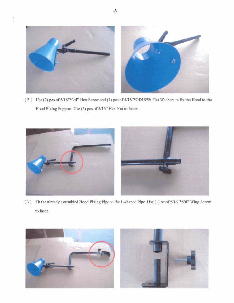
-8-

-9-

-10-

-11-

-12-
Warranty DisclaimerAir Systems’ manufactured equipment is warranted to the original user against defects in workman-ship or materials under normal use for one year after date of purchase. Any part which is deter-mined by Air Systems to be defective in material or workmanship will be, as the exclusive remedy,repaired or replaced at Air Systems’ option. This warranty does not apply to electrical systems orelectronic components. Electrical parts are warranted, to the original user, for 90 days from thedate of sale. During the warranty period, electrical components will be repaired or replaced at AirSystems’ option.NO OTHER WARRANTY, EXPRESSED OR IMPLIED, AS TO DESCRIPTION, QUAL-ITY, MERCHANTABILITY, FITNESS FOR A PARTICULAR PURPOSE, OR ANYOTHER MATTER IS GIVEN BY AIR SYSTEMS IN CONNECTION HEREWITH. UN-DER NO CIRCUMSTANCES SHALL THE SELLER BE LIABLE FOR LOSS OFPROFITS, ANY OTHER DIRECT OR INDIRECT COSTS, EXPENSES, LOSSES ORDAMAGES ARISING OUT OF DEFECTS IN, OR FAILURE OF THE PRODUCT ORANY PART THEREOF.The purchaser shall be solely responsible for compliance with all applicable Federal, State andLocal OSHA and/or MSHA requirements. Although Air Systems International believes that itsproducts, if operated and maintained as shipped from the factory and in accordance with our “op-erations manual”, conform to OSHA and/or MSHA requirements, there are no implied or expressedwarranties of such compliance extending beyond the limited warranty described herein. Productdesigns and specifications are subject to change without notice. Rev 2 12/98
Air leaks are not covered under warranty except when they result from a defective systemcomponent, i.e. an on/off valve or regulator or upon initial delivery due to poor workman-ship. Air leaks due to poor delivery or damage will be covered under delivery claims. Minorair leaks are part of routine service and maintenance and are the responsibility of the cus-tomer just as are filters and oil changes.