Embed Size (px)
Citation preview
PFC Lightweight Composite Push Up Mast
Operating Manual South Midlands Communications Ltd SM House, School Close Chandlers Ford Industrial Estate Eastleigh, Hampshire SO53 4BY United Kingdom Tel: +44 (0)23 8024 6200 Email: [email protected] Web: www.smc-comms.com


Preface SMC - South Midlands Communications Ltd was established in 1958 and initially specialized in antenna support masts, towers and HF antennas. SMC is now recognized globally as a specialist communications company.
Over the last 50 years the SMC product range has grown to include pneumatic telescopic masts, aluminium lattice masts, high-level photography solutions, Mil’ specification antenna positioner’s and two way radio products including GPS, AVLS and data transfer.
SMC are able to advise, design, supply and install mobile communications systems, from the simple to more complex and integrated networks.
Although every care is taken in the production of this publication it may contain technical inaccuracies or typographical errors. SMC may make improvements and or changes in the product detailed in this manual at any time without notice.
Correspondence regarding this publication should be addressed to:
South Midlands Communications Ltd SM House, School Close
Chandlers Ford Industrial Estate Eastleigh, Hampshire
SO53 4BY United Kingdom
Tel: +44 (0)23 8024 6200 Fax: +44 (0)23 8024 6206
Email: [email protected] Web: www.smc-comms.com
PFC Mast, Operating Manual MAN-00023 ISSUE 4
1
Contents Safety Information ............................................................................................ 2
Product Information .......................................................................................... 4
Long Duration Storage ................................................................................. 4
PFC Specification ............................................................................................ 5
Options & Accessories ..................................................................................... 6
Set-Up .............................................................................................................. 6
Guy Assembly .............................................................................................. 6
PFC Guy Radii ............................................................................................. 7
Base Guy Assembly ................................................................................. 7
Middle & Top Guy Assembly ..................................................................... 7
Installation .................................................................................................... 8
Locking Collars ............................................................................................. 9
Operating Instructions .................................................................................... 10
Raising the Mast ......................................................................................... 10
Lowering the Mast ...................................................................................... 10
Maintenance .................................................................................................. 11
Notes ............................................................................................................. 12
Tables Table.1: PFC Specification .............................................................................. 5
Table.2: PFC Guy Radii ................................................................................... 7
Figures
Fig.1: Mast Headload & Wind Speed ............................................................... 5
Fig.2: Guy Assemblies ..................................................................................... 6
Fig.3: PFC Guy Radii ....................................................................................... 7
Fig.4: Stake Angle ............................................................................................ 8
Fig.5: Guy Installation ...................................................................................... 8
Fig.6: Locking Collar Spacing .......................................................................... 9
PFC Mast, Operating Manual MAN-00023 ISSUE 4
2
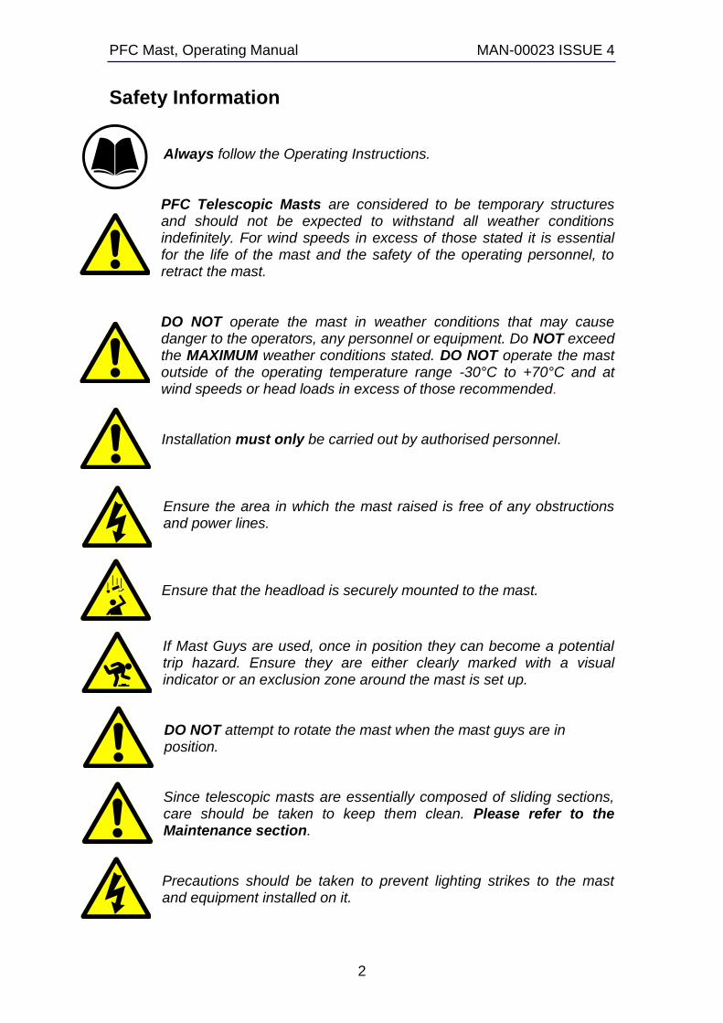
Safety Information Always follow the Operating Instructions. PFC Telescopic Masts are considered to be temporary structures and should not be expected to withstand all weather conditions indefinitely. For wind speeds in excess of those stated it is essential for the life of the mast and the safety of the operating personnel, to retract the mast.
DO NOT operate the mast in weather conditions that may cause danger to the operators, any personnel or equipment. Do NOT exceed the MAXIMUM weather conditions stated. DO NOT operate the mast outside of the operating temperature range -30°C to +70°C and at wind speeds or head loads in excess of those recommended. Installation must only be carried out by authorised personnel. Ensure the area in which the mast raised is free of any obstructions and power lines. Ensure that the headload is securely mounted to the mast.
If Mast Guys are used, once in position they can become a potential trip hazard. Ensure they are either clearly marked with a visual indicator or an exclusion zone around the mast is set up. DO NOT attempt to rotate the mast when the mast guys are in position. Since telescopic masts are essentially composed of sliding sections, care should be taken to keep them clean. Please refer to the Maintenance section. Precautions should be taken to prevent lighting strikes to the mast and equipment installed on it.
PFC Mast, Operating Manual MAN-00023 ISSUE 4
3
The warranty will be invalidated in the event that:
Recommended service intervals are not maintained.. The mast is operated within a moving vehicle or trailer. Maximum head load or wind load are exceeded. The mast is operated at temperature outside the recommended range. Non-accredited installation, or service work is undertaken. SMC or Hilomast LLC supplied spares are not used. The installation and operating instructions are not adhered to. The locking collar is over tightened.
Failure to observe any of the warnings in this manual may result in personal injury, death, or equipment damage. South Midlands Communications Ltd. (SMC)/Hilomast LLC do not accept responsibility or liability for unauthorised use or actions outside of those recommended.

PFC Mast, Operating Manual MAN-00023 ISSUE 4
4
Product Information The PFC series of the telescopic masts have a base section diameter of 88.7mm and are operated by hand. The mast sections are made of a fibreglass/carbon fibre sandwich that gives a very lightweight, durable mast. Each section has a locking collar and dampening valves that control the speed at which the mast is lowered. The mast is designed for portable applications such as mobile communication equipment.
Long Duration Storage
If possible, store in an upright position.
PFC Mast, Operating Manual MAN-00023 ISSUE 4
5
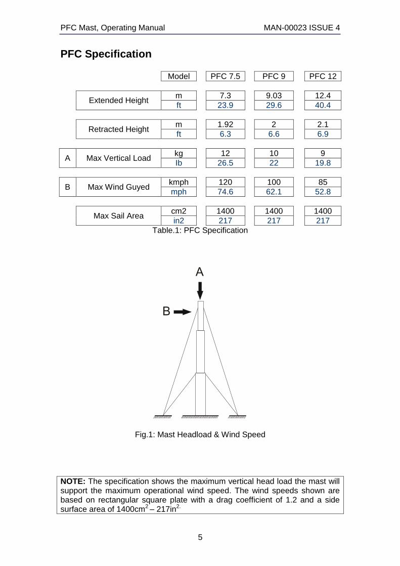
PFC Specification
Model PFC 7.5 PFC 9 PFC 12
Extended Height
m 7.3 9.03 12.4
ft 23.9 29.6 40.4
Retracted Height
m 1.92 2 2.1
ft 6.3 6.6 6.9
A Max Vertical Load kg 12 10 9
Ib 26.5 22 19.8
B Max Wind Guyed kmph 120 100 85
mph 74.6 62.1 52.8
Max Sail Area
cm2 1400 1400 1400
in2 217 217 217
Table.1: PFC Specification
Fig.1: Mast Headload & Wind Speed
NOTE: The specification shows the maximum vertical head load the mast will support the maximum operational wind speed. The wind speeds shown are based on rectangular square plate with a drag coefficient of 1.2 and a side surface area of 1400cm2 – 217in2.
PFC Mast, Operating Manual MAN-00023 ISSUE 4
6
Options & Accessories Nato Spigots are available, for interfacing between the mast and
antenna.
U-bolts and clamps are available to fasten antennas directly to the top section of the mast.
Halyard Kits are also an option.
DO NOT over tighten clamps as this can damage the mast.
Set-Up For erecting masts on open ground, Base Guy Assemblies are available as they are the strongest / best suited for field mounting. Base guys are the minimum mounting arrangement available for the installation of the PFC mast series however, middle and top guys are provided for use in inclement weather conditions and to add directional stability.
Guy Assembly
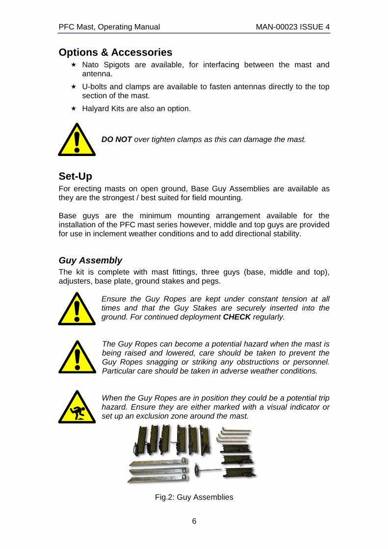
The kit is complete with mast fittings, three guys (base, middle and top), adjusters, base plate, ground stakes and pegs.
Ensure the Guy Ropes are kept under constant tension at all times and that the Guy Stakes are securely inserted into the ground. For continued deployment CHECK regularly.
The Guy Ropes can become a potential hazard when the mast is being raised and lowered, care should be taken to prevent the Guy Ropes snagging or striking any obstructions or personnel. Particular care should be taken in adverse weather conditions.
When the Guy Ropes are in position they could be a potential trip hazard. Ensure they are either marked with a visual indicator or set up an exclusion zone around the mast.
Fig.2: Guy Assemblies
PFC Mast, Operating Manual MAN-00023 ISSUE 4
7
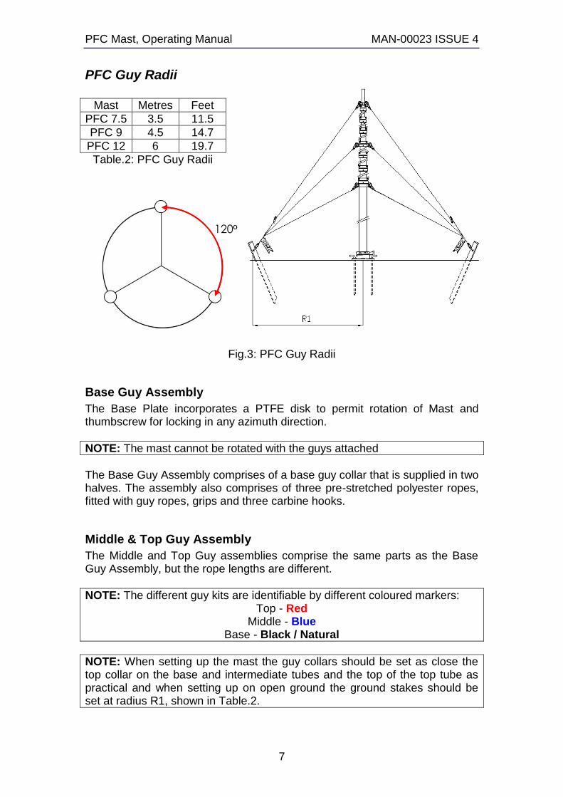
PFC Guy Radii
Mast Metres Feet
PFC 7.5 3.5 11.5
PFC 9 4.5 14.7
PFC 12 6 19.7
Table.2: PFC Guy Radii
Fig.3: PFC Guy Radii
Base Guy Assembly
The Base Plate incorporates a PTFE disk to permit rotation of Mast and thumbscrew for locking in any azimuth direction.
NOTE: The mast cannot be rotated with the guys attached
The Base Guy Assembly comprises of a base guy collar that is supplied in two halves. The assembly also comprises of three pre-stretched polyester ropes, fitted with guy ropes, grips and three carbine hooks.
Middle & Top Guy Assembly
The Middle and Top Guy assemblies comprise the same parts as the Base Guy Assembly, but the rope lengths are different.
NOTE: The different guy kits are identifiable by different coloured markers: Top - Red
Middle - Blue Base - Black / Natural
NOTE: When setting up the mast the guy collars should be set as close the top collar on the base and intermediate tubes and the top of the top tube as practical and when setting up on open ground the ground stakes should be set at radius R1, shown in Table.2.
120º
PFC Mast, Operating Manual MAN-00023 ISSUE 4
8
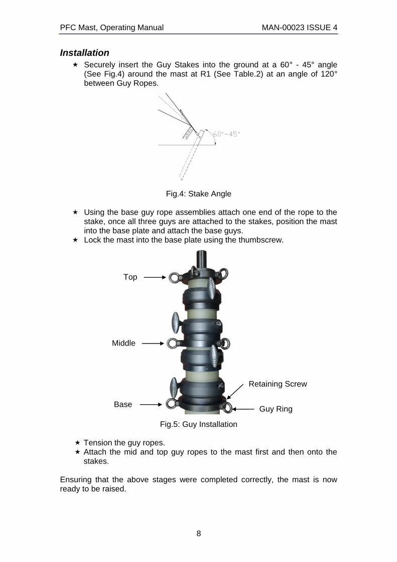
Installation
Securely insert the Guy Stakes into the ground at a 60° - 45° angle (See Fig.4) around the mast at R1 (See Table.2) at an angle of 120° between Guy Ropes.
Fig.4: Stake Angle
Using the base guy rope assemblies attach one end of the rope to the stake, once all three guys are attached to the stakes, position the mast into the base plate and attach the base guys.
Lock the mast into the base plate using the thumbscrew.
Fig.5: Guy Installation
Tension the guy ropes. Attach the mid and top guy ropes to the mast first and then onto the
stakes.
Ensuring that the above stages were completed correctly, the mast is now ready to be raised.
Top
Base
Middle
Guy Ring
Retaining Screw
PFC Mast, Operating Manual MAN-00023 ISSUE 4
9
Locking Collars
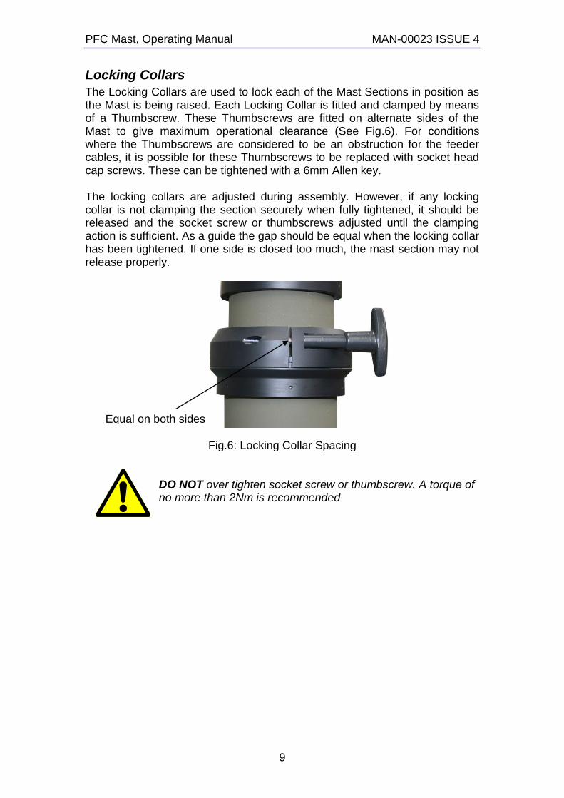
The Locking Collars are used to lock each of the Mast Sections in position as the Mast is being raised. Each Locking Collar is fitted and clamped by means of a Thumbscrew. These Thumbscrews are fitted on alternate sides of the Mast to give maximum operational clearance (See Fig.6). For conditions where the Thumbscrews are considered to be an obstruction for the feeder cables, it is possible for these Thumbscrews to be replaced with socket head cap screws. These can be tightened with a 6mm Allen key. The locking collars are adjusted during assembly. However, if any locking collar is not clamping the section securely when fully tightened, it should be released and the socket screw or thumbscrews adjusted until the clamping action is sufficient. As a guide the gap should be equal when the locking collar has been tightened. If one side is closed too much, the mast section may not release properly.
Fig.6: Locking Collar Spacing
DO NOT over tighten socket screw or thumbscrew. A torque of no more than 2Nm is recommended
Equal on both sides
PFC Mast, Operating Manual MAN-00023 ISSUE 4
10
Operating Instructions Ensure the mast fixings i.e. mast base plate and the base guy ropes are secure before raising the mast.
Raising the Mast
All locking collars with the exception of the top one should be securely tightened by turning the thumbscrew in a clockwise direction.
Attach the middle and top guys (if required) Raise the top section by hand. When the top section is fully extended
tighten the thumbscrew. Release the thumbscrew on the next section down and push up the
next section. When that section is fully extended tighten the thumbscrew.
DO NOT over tighten socket screw or thumbscrew. A torque of no more than 2Nm is recommended
Repeat these stages until the mast is fully extended. Once the mast is fully extended attach the middle and top guy ropes to
the ground stakes and tension the guy ropes.
Lowering the Mast
Un-clip the middle and top guys from the ground stake (if used) Release the thumbscrew on the lowest collar, the section above will
retract. Tighten the thumbscrew to secure section. Release the thumbscrew on the next section, the section above that
will retract. Tighten the thumbscrew to secure section. Repeat these stages until the mast is fully retracted.
NOTE: The rate of retraction cannot be increased.
When lowering the mast take care to keep hands clear of collars and thumbscrews.

PFC Mast, Operating Manual MAN-00023 ISSUE 4
11
Maintenance Inspect the mast sections at four-week intervals or every 200 operations, whichever occurs first. If the mast has been used in a dusty environment resulting in a build up of contaminants on the surface of the tubes, then this must be removed. Wiping each section with a cloth can do this. If any other maintenance is required, return the mast and guy kit to SMC.

PFC Mast, Operating Manual MAN-00023 ISSUE 4
12
Notes