Embed Size (px)
Citation preview
8/11/2019 Lattice Towers and Masts Introduction
http://slidepdf.com/reader/full/lattice-towers-and-masts-introduction 1/17
Lattice Towers and Masts
OBJECTIVE/SCOPE
To describe typical lattice tower design problems; to introduce the background for the load requirements; to emphasize the connection between basic
functional requirements and overall structural design; to explain the principles of the structural analysis and the choice of structural details.
The lecture is confined to the detailed description of the design of one particular type of tower, i.e. the high voltage transmission tower.
PREREQUISITES
None.
SUMMARY
The common structural problems in the design of steel lattice towers for different purposes are outlined.
The details of design are discussed in relation to a specific category of tower, the high voltage transmission tower. The influence on the tower design
of the user's functional demands is explained and the background for the load assumptions is pointed out.
Different aspects affecting the overall design and the detailing are discussed and problems connected with the structural analysis are explained. The
effect of joint eccentricities is discussed on the basis of a very common design example using angle sections. The use of different detailing is
mentioned.
The need for erection joints is stated and the types of joints are discussed. Corrosion protection is briefly dealt with and its influence on the towerdesign is pointed out.
Tower foundations are not treated in this lecture.
1. INTRODUCTION
Towers or masts are built in order to fulfil the need for placing objects or persons at a certain level above the ground. Typical examples are:
single towers for antennae, floodlight projectors or platforms for inspection, supervision or tourist purposes. systems of towers and wires serving transport purposes, such as ski lifts, ropeways, or power transmission lines.
For all kinds of towers the designer should thoroughly study the user's functional requirements in order to reach the best possible design for the particular structure. For example, it is extremely important to keep the flexural and torsional rotations of an antenna tower within narrow limits in
order to ensure the proper functioning of the equipment.
The characteristic dimension of a tower is its height. It is usually several times larger than the horizontal dimensions. Frequently the area which may
be occupied at ground level is very limited and, thus, rather slender structures are commonly used.
Another characteristic feature is that a major part of the tower design load comes from the wind force on the tower itself and its equipment, including
wires suspended by the tower. To provide the necessary flexural rigidity and, at the same time, keeping the area exposed to the wind as small as
possible, lattice structures are frequently preferred to more compact 'solid' structures.
Bearing in mind these circumstances, it is not surprising to find that the design problems are almost the same irrespective of the purpose to be served
by the tower. Typical design problems are:
establishment of load requirements.
consistency between loads and tower design.
establishment of overall design, including choice of number of tower legs.
consistency between overall design and detailing.
detailing with or without node eccentricities.
sectioning of structure for transport and erection.
In this lecture, towers for one particular purpose, i.e. the high voltage transmission tower, have been selected for discussion.
2. HIGH VOLTAGE TRANSMISSION TOWERS
2.1 Background
The towers support one or more overhead lines serving the energy distribution. Most frequently three-phase AC circuits are used requiring three live
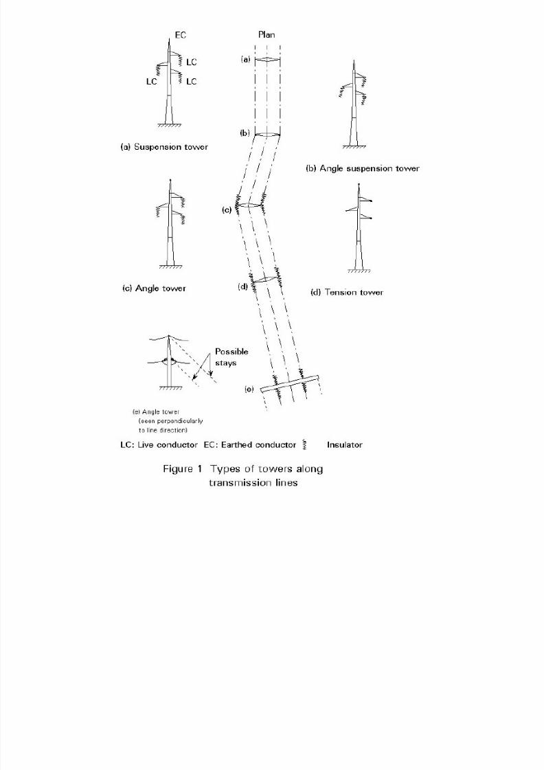
conductors each. To provide safety against lightning, earthed conductors are placed at the top of the tower, see Figures 1 and 2.
8/11/2019 Lattice Towers and Masts Introduction
http://slidepdf.com/reader/full/lattice-towers-and-masts-introduction 2/17
8/11/2019 Lattice Towers and Masts Introduction
http://slidepdf.com/reader/full/lattice-towers-and-masts-introduction 3/17
The live conductors are supported by insulators, the length of which increases with increasing voltage of the circuit. To prevent short circuit between
live and earthed parts, including the surrounding environment, minimum mutual clearances are prescribed.
Mechanically speaking, the conductors behave like wires whose sag between their points of support depends on the temperature and the wire tension,the latter coming from the external loads and the pre-tensioning of the conductor. As explained in Section 2.4, the size of the tension forces in the
conductor has a great effect upon the tower design.
2.2 Types of Towers
An overhead transmission line connects two nodes of the power supply grid. The route of the line has as few changes in direction as possible.
Depending on their position in the line various types of towers occur such as (a) suspension towers, (b) angle suspension towers, (c) angle towers, (d)tension towers and, (e) terminal towers, see Figure 1. Tension towers serve as rigid points able to prevent progressive collapse of the entire line. They
may be designed to serve also as angle towers.
To the above-mentioned types should be added special towers required at the branching of two or more lines.
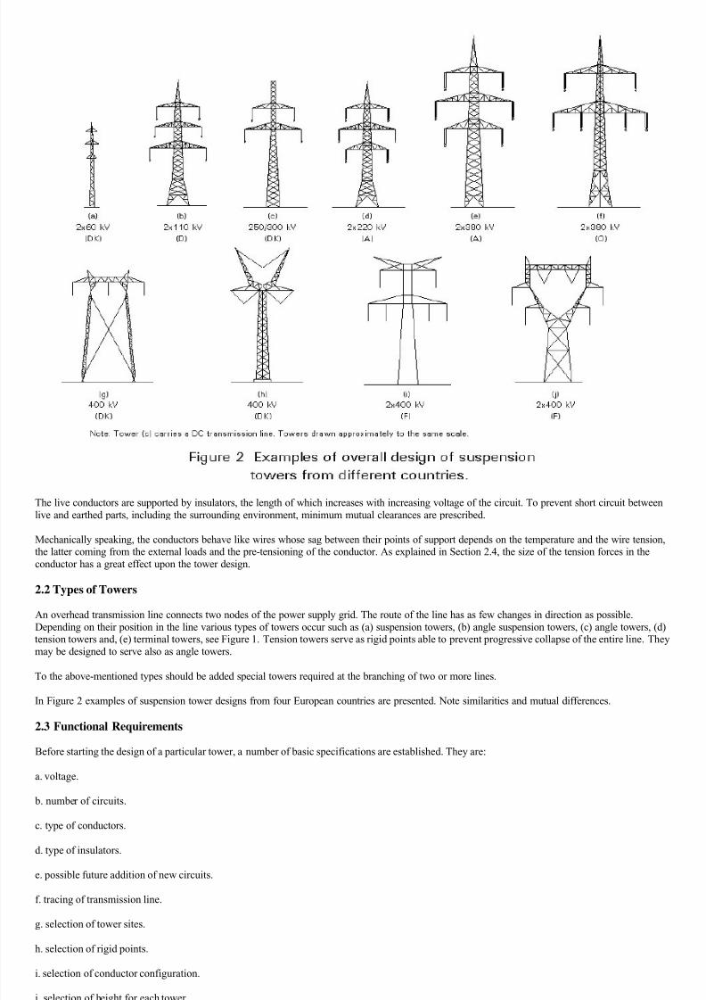
In Figure 2 examples of suspension tower designs from four European countries are presented. Note similarities and mutual differences.
2.3 Functional Requirements
Before starting the design of a particular tower, a number of basic specifications are established. They are:
a. voltage.
b. number of circuits.
c. type of conductors.
d. type of insulators.
e. possible future addition of new circuits.
f. tracing of transmission line.
g. selection of tower sites.
h. selection of rigid points.
i. selection of conductor configuration.
j. selection of height for each tower.
8/11/2019 Lattice Towers and Masts Introduction
http://slidepdf.com/reader/full/lattice-towers-and-masts-introduction 4/17
The tower designer should notice that the specifications reflect a number of choices. However, the designer is rarely in a position to bring about
desirable changes in these specifications. Therefore, functional requirements are understood here as the electrical requirements which guide the towerdesign after establishment of the basic specifications.
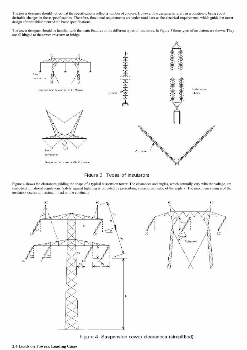
The tower designer should be familiar with the main features of the different types of insulators. In Figure 3 three types of insulators are shown. They
are all hinged at the tower crossarm or bridge.
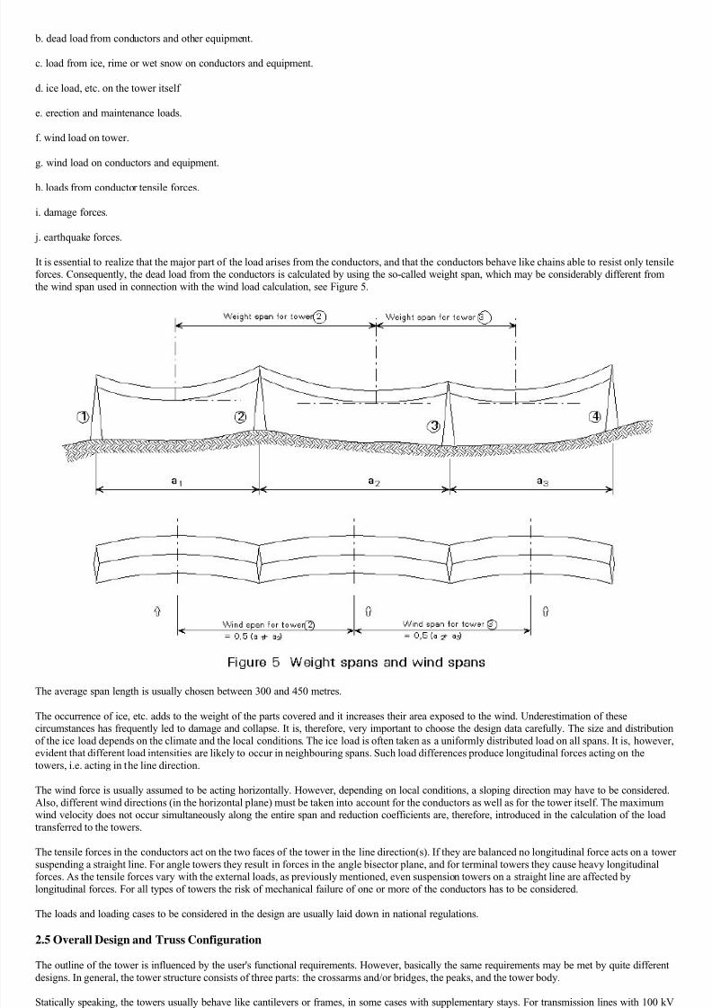
Figure 4 shows the clearances guiding the shape of a typical suspension tower. The clearances and angles, which naturally vary with the voltage, areembodied in national regulations. Safety against lightning is provided by prescribing a maximum value of the angle v. The maximum swing u of the
insulators occurs at maximum load on the conductor.
2.4 Loads on Towers, Loading Cases
The loads acting on a transmission tower are:
a. dead load of tower.
8/11/2019 Lattice Towers and Masts Introduction
http://slidepdf.com/reader/full/lattice-towers-and-masts-introduction 5/17
b. dead load from conductors and other equipment.
c. load from ice, rime or wet snow on conductors and equipment.
d. ice load, etc. on the tower itself
e. erection and maintenance loads.
f. wind load on tower.
g. wind load on conductors and equipment.
h. loads from conductor tensile forces.
i. damage forces.
j. earthquake forces.
It is essential to realize that the major part of the load arises from the conductors, and that the conductors behave like chains able to resist only tensileforces. Consequently, the dead load from the conductors is calculated by using the so-called weight span, which may be considerably different from
the wind span used in connection with the wind load calculation, see Figure 5.
The average span length is usually chosen between 300 and 450 metres.
The occurrence of ice, etc. adds to the weight of the parts covered and it increases their area exposed to the wind. Underestimation of thesecircumstances has frequently led to damage and collapse. It is, therefore, very important to choose the design data carefully. The size and distribution
of the ice load depends on the climate and the local conditions. The ice load is often taken as a uniformly distributed load on all spans. It is, however,evident that different load intensities are likely to occur in neighbouring spans. Such load differences produce longitudinal forces acting on the
towers, i.e. acting in the line direction.
The wind force is usually assumed to be acting horizontally. However, depending on local conditions, a sloping direction may have to be considered.
Also, different wind directions (in the horizontal plane) must be taken into account for the conductors as well as for the tower itself. The maximumwind velocity does not occur simultaneously along the entire span and reduction coefficients are, therefore, introduced in the calculation of the load
transferred to the towers.
The tensile forces in the conductors act on the two faces of the tower in the line direction(s). If they are balanced no longitudinal force acts on a tower
suspending a straight line. For angle towers they result in forces in the angle bisector plane, and for terminal towers they cause heavy longitudinalforces. As the tensile forces vary with the external loads, as previously mentioned, even suspension towers on a straight line are affected by
longitudinal forces. For all types of towers the risk of mechanical failure of one or more of the conductors has to be considered.
The loads and loading cases to be considered in the design are usually laid down in national regulations.
2.5 Overall Design and Truss Configuration
The outline of the tower is influenced by the user's functional requirements. However, basically the same requirements may be met by quite different
designs. In general, the tower structure consists of three parts: the crossarms and/or bridges, the peaks, and the tower body.
Statically speaking, the towers usually behave like cantilevers or frames, in some cases with supplementary stays. For transmission lines with 100 kV
voltage or more, the use of steel lattice structures is nearly always found advantageous because they are:
easily adaptable to any shape or height of tower.
easily divisible in sections suitable for transport and erection.
8/11/2019 Lattice Towers and Masts Introduction
http://slidepdf.com/reader/full/lattice-towers-and-masts-introduction 6/17
easy to repair, strengthen and extend.
durable when properly protected against corrosion.
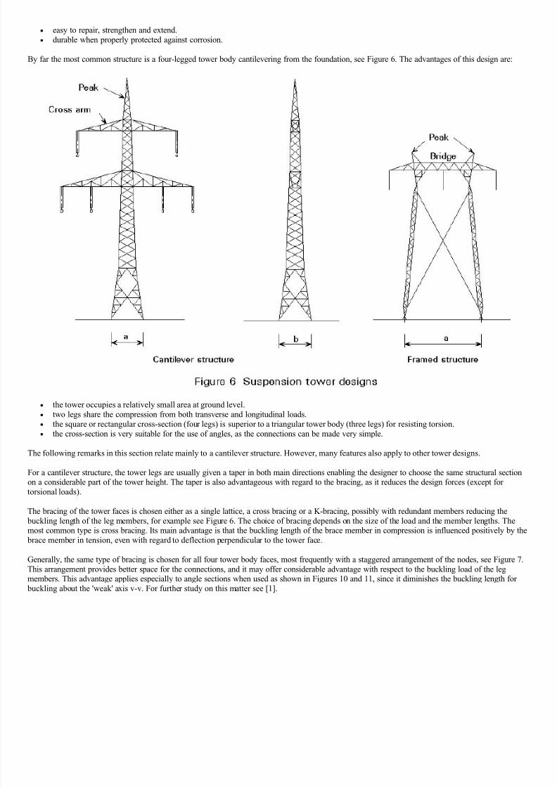
By far the most common structure is a four-legged tower body cantilevering from the foundation, see Figure 6. The advantages of this design are:
the tower occupies a relatively small area at ground level.
two legs share the compression from both transverse and longitudinal loads. the square or rectangular cross-section (four legs) is superior to a triangular tower body (three legs) for resisting torsion.
the cross-section is very suitable for the use of angles, as the connections can be made very simple.
The following remarks in this section relate mainly to a cantilever structure. However, many features also apply to other tower designs.
For a cantilever structure, the tower legs are usually given a taper in both main directions enabling the designer to choose the same structural sectionon a considerable part of the tower height. The taper is also advantageous with regard to the bracing, as it reduces the design forces (except for
torsional loads).
The bracing of the tower faces is chosen either as a single lattice, a cross bracing or a K-bracing, possibly with redundant members reducing the
buckling length of the leg members, for example see Figure 6. The choice of bracing depends on the size of the load and the member lengths. Themost common type is cross bracing. Its main advantage is that the buckling length of the brace member in compression is influenced positively by the
brace member in tension, even with regard to deflection perpendicular to the tower face.
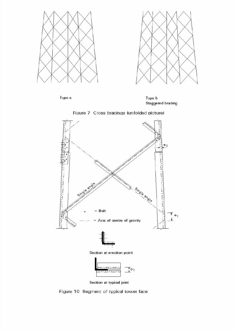
Generally, the same type of bracing is chosen for all four tower body faces, most frequently with a staggered arrangement of the nodes, see Figure 7.
This arrangement provides better space for the connections, and it may offer considerable advantage with respect to the buckling load of the legmembers. This advantage applies especially to angle sections when used as shown in Figures 10 and 11, since it diminishes the buckling length for
buckling about the 'weak' axis v-v. For further study on this matter see [1].
8/11/2019 Lattice Towers and Masts Introduction
http://slidepdf.com/reader/full/lattice-towers-and-masts-introduction 7/17
8/11/2019 Lattice Towers and Masts Introduction
http://slidepdf.com/reader/full/lattice-towers-and-masts-introduction 8/17
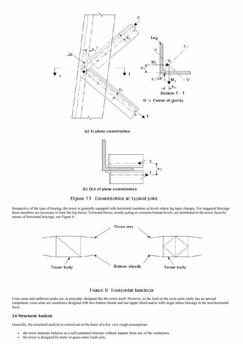
Irrespective of the type of bracing, the tower is generally equipped with horizontal members at levels where leg taper changes. For staggered bracingsthese members are necessary to 'turn' the leg forces. Torsional forces, mostly acting at crossarm bottom levels, are distributed to the tower faces by
means of horizontal bracings, see Figure 8.
Cross arms and earthwire peaks are, in principle, designed like the tower itself. However, as the load on the cross arms rarely has an upward
component, cross arms are sometimes designed with two bottom chords and one upper chord and/or with single lattice bracings in the non-horizontalfaces.
2.6 Structural Analysis
Generally, the structural analysis is carried out on the basis of a few very rough assumptions:
the tower structure behaves as a self-contained structure without support from any of the conductors.
the tower is designed for static or quasi-static loads only.
These assumptions do not reflect the real behaviour of the total system, i.e. towers and conductors, particularly well. However, they provide a basis
from simple calculations which have broadly led to satisfactory results.
8/11/2019 Lattice Towers and Masts Introduction
http://slidepdf.com/reader/full/lattice-towers-and-masts-introduction 9/17
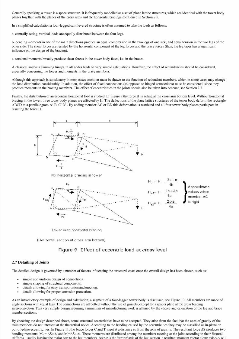
Generally speaking, a tower is a space structure. It is frequently modelled as a set of plane lattice structures, which are identical with the tower body
planes together with the planes of the cross arms and the horizontal bracings mentioned in Section 2.5.
In a simplified calculation a four-legged cantilevered structure is often assumed to take the loads as follows:
a. centrally acting, vertical loads are equally distributed between the four legs.
b. bending moments in one of the main directions produce an equal compression in the two legs of one side, and equal tension in the two legs of the
other side. The shear forces are resisted by the horizontal component of the leg forces and the brace forces (thus, the leg taper has a significant
influence on the design of the bracing).
c. torsional moments broadly produce shear forces in the tower body faces, i.e. in the braces.
A classical analysis assuming hinges in all nodes leads to very simple calculations. However, the effect of redundancies should be considered,
especially concerning the forces and moments in the brace members.
Although this approach is satisfactory in most cases attention must be drawn to the function of redundant members, which in some cases may change
the load distribution considerably. In addition, the effect of fixed connections (as opposed to hinged connections) must be considered, since they
produce moments in the bracing members. The effect of eccentricities in the joints should also be taken into account, see Section 2.7.
Finally, the distribution of an eccentric horizontal load is studied. In Figure 9 the force H is acting at the cross arm bottom level. Without horizontal
bracing in the tower, three tower body planes are affected by H. The deflections of the plane lattice structures of the tower body deform the rectangle
ABCD to a parallelogram A B C D . By adding member AC or BD this deformation is restricted and all four tower body planes participate in
resisting the force H.
2.7 Detailing of Joints
The detailed design is governed by a number of factors influencing the structural costs once the overall design has been chosen, such as:
simple and uniform design of connections.
simple shaping of structural components.
details allowing for easy transportation and erection.
details allowing for proper corrosion protection.
As an introductory example of design and calculation, a segment of a four-legged tower body is discussed, see Figure 10. All members are made ofangle sections with equal legs. The connections are all bolted without the use of gussets, except for a spacer plate at the cross bracing
interconnection. This very simple design requiring a minimum of manufacturing work is attained by the choice and orientation of the leg and brace
member sections.
By choosing the design described above, some structural eccentricities have to be accepted. They arise from the fact that the axes of gravity of thetruss members do not intersect at the theoretical nodes. According to the bending caused by the eccentricities they may be classified as in-plane or
out-of-plane eccentricities. In Figure 11, the brace forces C and T meet at a distance eo from the axis of gravity. The resultant force S produces two
bending moments: Me = S eo and Mf =S e1. These moments are distributed among the members meeting at the joint according to their flexuralstiffness, usually leaving the major part to the leg members. As z-z is the 'strong' axis of the leg section, a resultant moment vector along axis v-v will
be advantageous. This is achieved, when eo=-e1 . In this case C and T intersect approximately at the middle of the leg of the section. Usually this
situation is not fully practicable without adding a gusset plate to the joint.
8/11/2019 Lattice Towers and Masts Introduction
http://slidepdf.com/reader/full/lattice-towers-and-masts-introduction 10/17
Additional eccentricity problems occur when the bolts are not placed on the axis of gravity, especially when only one bolt is used in the connection
(eccentricities ec and et).
The out-of-plane eccentricity causing a torsional moment, V = H e2, acting on the leg may be measured between the axes of gravity for the bracemembers (see Figure 11). However, the torsional stiffness of the leg member may be so moderate - depending on its support conditions - that V
cannot be transferred by the leg and, consequently, e2 must diminish. The latter causes bending out-of-plane in the brace members.
The leg joint shown in Figure 10 is a splice joint in which an eccentricity e3 may occur. In this case there is a change of leg section, or the gravityaxis for the four (or two) splice plates in common does not coincide with the axis of the leg(s). For legs in compression the joint must be designed
with some flexural rigidity to prevent unwanted action as a hinge.
The joint eccentricities have to be carefully considered in the design. As the lower part of the leg usually is somewhat oversized at the joint - this is,in fact, the reason for changing leg section at the joint - a suitable model would be to consider the upper part of the leg centrally loaded and thus, let
the lower part resist the eccentricity moment. The splice plates and the bolt connections must then be designed in accordance with this model.
The bolted connections might easily be replaced by welded connections with no major changes of the design. However, except for small structures,
bolted connections are generally preferred, as they offer the opportunity to assemble the structural parts without damaging the corrosion protection,
see Section 2.8.
This introductory example is very typical of the design with angle sections. Nevertheless some additional comments should be added concerning the
use of gussets and multiple angle sections.
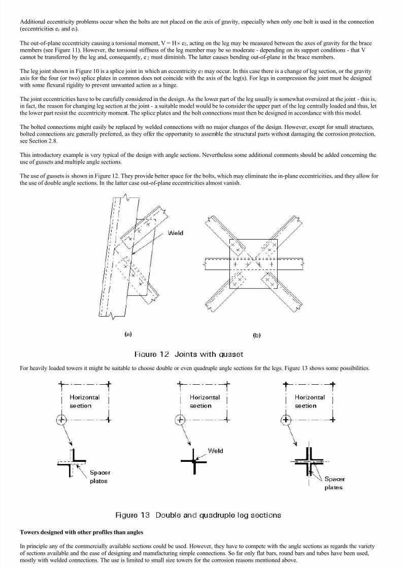
The use of gussets is shown in Figure 12. They provide better space for the bolts, which may eliminate the in-plane eccentricities, and they allow for
the use of double angle sections. In the latter case out-of-plane eccentricities almost vanish.
For heavily loaded towers it might be suitable to choose double or even quadruple angle sections for the legs. Figure 13 shows some possibilities.
Towers designed with other profiles than angles
In principle any of the commercially available sections could be used. However, they have to compete with the angle sections as regards the variety
of sections available and the ease of designing and manufacturing simple connections. So far only flat bars, round bars and tubes have been used,
mostly with welded connections. The use is limited to small size towers for the corrosion reasons mentioned above.
In other contexts, e.g. high rise TV towers, circular sections may be more interesting because their better shape reduces wind action.
Construction joints and erection joints
8/11/2019 Lattice Towers and Masts Introduction
http://slidepdf.com/reader/full/lattice-towers-and-masts-introduction 11/17
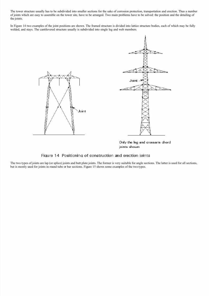
The tower structure usually has to be subdivided into smaller sections for the sake of corrosion protection, transportation and erection. Thus a number
of joints which are easy to assemble on the tower site, have to be arranged. Two main problems have to be solved: the position and the detailing ofthe joints.
In Figure 14 two examples of the joint positions are shown. The framed structure is divided into lattice structure bodies, each of which may be fully
welded, and stays. The cantilevered structure usually is subdivided into single leg and web members.
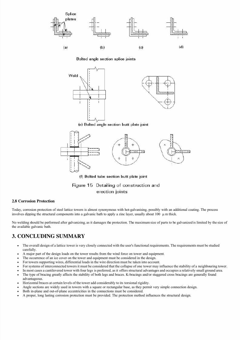
The two types of joints are lap (or splice) joints and butt plate joints. The former is very suitable for angle sections. The latter is used for all sections,
but is mostly used for joints in round tube or bar sections. Figure 15 shows some examples of the two types.
8/11/2019 Lattice Towers and Masts Introduction
http://slidepdf.com/reader/full/lattice-towers-and-masts-introduction 12/17
2.8 Corrosion Protection
Today, corrosion protection of steel lattice towers is almost synonymous with hot-galvanising, possibly with an additional coating. The process
involves dipping the structural components into a galvanic bath to apply a zinc layer, usually about 100 m thick.
No welding should be performed after galvanizing, as it damages the protection. The maximum size of parts to be galvanized is limited by the size of
the available galvanic bath.
3. CONCLUDING SUMMARY The overall design of a lattice tower is very closely connected with the user's functional requirements. The requirements must be studied
carefully.
A major part of the design loads on the tower results from the wind force on tower and equipment.
The occurrence of an ice cover on the tower and equipment must be considered in the design.
For towers supporting wires, differential loads in the wire direction must be taken into account.
For systems of interconnected towers it must be considered that the collapse of one tower may influence the stability of a neighbouring tower. In most cases a cantilevered tower with four legs is preferred, as it offers structural advantages and occupies a relatively small ground area.
The type of bracing greatly affects the stability of both legs and braces. K-bracings and/or staggered cross bracings are generally found
advantageous.
Horizontal braces at certain levels of the tower add considerably to its torsional rigidity.
Angle sections are widely used in towers with a square or rectangular base, as they permit very simple connection design.
Both in-plane and out-of-plane eccentricities in the connections must be considered.
A proper, long lasting corrosion protection must be provided. The protection method influences the structural design.
8/11/2019 Lattice Towers and Masts Introduction
http://slidepdf.com/reader/full/lattice-towers-and-masts-introduction 13/17
Guyed Masts
OBJECTIVE/SCOPE
To outline calculation methods for guyed masts, in particular manual calculation of erection tensions in guy ropes, and computer calculation of forces
in non-linear mode; to explain the main principles of non-linear calculation; to cover erection methods.
SUMMARY
The components of a guyed mast are described, i.e. mast, guy ropes, accessories, equipment.
Specific items of the calculation of guyed masts are introduced. The definition and manual calculation of erection tensions in guy ropes is described
together with the principles and computer calculation of forces and strains.
The fabrication and erection of guyed masts are briefly discussed.
1. INTRODUCTION
The permanent development of regional, national and international communications requires very high structures.
These structures are generally designed for the following purposes:
to support small antennae, such as TV or FM antennae: they consist of a series of panels, the height of which relates to the required area ofreception.
feeding cables which connect the panels to the transmitter at ground level.
to support antenna curtains: the antenna components are supported by a net of cables which is connected at the top of two towers; they are fed
by a parallel feeding curtain. These antennae are used for short wave transmission and their current dimensions are about 100m x 100m. to constitute an antenna by themselves for long wave transmission; the height of the radiating structure is equal to a half or a quarter of the
wave length.
Steel guyed masts may be designed specifically to meet the above needs since very high structures (up to 600 metres high) which are both light and
stiff can be designed and built in steel.
The present lecture does not give:
the detailed constitution of the different antenna types.
methods to improve the quality of the transmission (simultaneous use of several antennae).
2. THE DESCRIPTION OF A GUYED MAST
The component parts of a guyed mast are:
the foundations the steel mast, which generally has a pinned foot
the guy ropes
the structural accessories
the equipment.
2.1 The Foundations
It is not the purpose of the present lecture to describe the foundations in a detailed way. It is only indicated that:
the foundation under the foot of the mast is calculated to support a very big compression force. A moment is considered in addition for the
rare cases where the mast feet are fixed.
the foundations in which guy ropes are anchored are calculated to support the sloping tension force.
2.2 The Steel Mast
The mast may be considered as a continuous beam on elastic supports which are provided by the guy ropes. In most cases, it is a lattice column with
a square or equilateral triangle cross-section. It is also possible to design masts with a round tubular section.
For the masts with 3 faces, the most adequate section of the legs is a round hollow section or a round solid section. A circular flange is welded ontoeach end of each leg element. The leg elements are connected by bolting the flanges one to the other. The truss bars are bolted onto gusset plates
which are welded on the legs. The section of the truss bars consists of one or two connected angles or of a circular tube. Where circular tubes are
used, they are slotted and pressed at their ends in order to allow the bolted connection.
For masts with 4 faces, the same design can be used as for masts with 3 faces. Single angle legs or two cross-connected angle legs can also be used.
Where angle legs are used, the leg elements are connected together with bolted cover-plates. The truss bars are bolted onto the legs, either directly or
by bolted gusset plates. For this type of mast, there is no welding work.
A mast structure with 4 faces must have horizontal bracings which prevent deformation of the cross-section.
In general in the few cases where the mast has a round tubular section, the mast has a fixed foot. It is very difficult to make a pinned foot for a mast
with a tubular section. The mast elements are connected together by welded hollow flanges with external bolts.
2.3 The Guy Ropes
8/11/2019 Lattice Towers and Masts Introduction
http://slidepdf.com/reader/full/lattice-towers-and-masts-introduction 14/17
The guy ropes create elastic bearings with horizontal action on the mast. Where the mast has three truss faces, each bearing consists of three guy
ropes situated in the medium plane of the angle of two adjacent truss faces. Where the mast has four truss faces, each bearing consists of four guy
ropes each situated in a diagonal plane. Where the mast has a round hollow section, each bearing has three 120 spaced guy ropes or four 90 spacedguy ropes.
All the guy ropes (3 or 4) of a bearing form the same angle with the horizontal plane of between 30 and 60 .
The guy ropes are generally steel cables. In special cases where a guy rope enters the transmission field, cables of synthetic materials can be used.
The three or four guy ropes which constitute a bearing must be of the same material.
The criteria for choosing cables are as follows:
high strength
high Young's modulus
no rotation around the cable axis when tension varies
ability to be easily protected from corrosion
ability to be rolled for transportation.
It is always necessary to find the best compromise between the two first criteria and the fifth. The above analysis generally leads to the use of all-
steel cables with large diameter wires, mainly one twist cables.
Guy ropes are provided with a socket at each end. The sockets are cast steel pieces of a conical shape and two parallel flanges which receive a
connecting pin. The cable is entered in the hollow conical part of the socket, the wires constituting the cable are separated and bent to form a regular"flower" which is introduced into the socket. The socket cavity is then filled with a molten alloy. At one of the cable ends, the pin perpendicular to
cable connects the bottom socket to the foundation anchor. At the other end, the pin connects the top socket to a thick gusset plate welded onto the
mast leg.
2.4 Structural Accessories
The structural accessories are generally supplied by the steel manufacturer of the mast and include:
the accessories for access to the mast, i.e. ladders with a cage or with a safety rail, the rest platforms and the work platforms. the accessories which support feeders.
the accessories for the electric insulation of the radiating masts: a ceramic insulator is provided under the mast foot and an insulator for each
guy rope. The insulators only withstand compression so that their connection to guy ropes under tension requires special equipment.
the accessories for the adjustment of the rope tensions which are placed between the bottom socket and the foundation anchor.
2.5 Equipment
The equipment is generally not supplied by the steel manufacturer of the mast and includes:
different antennae
feeding cables
beacon equipment
lightning protection.
3. THE DESIGN OF GUYED MASTS
The design of guyed masts - as other structures - contains two main steps:
initial dimensioning
final dimensioning and checking.
3.1 Initial Dimensioning
In this step, the engineer chooses a first set of sections for the bar elements which constitute the mast and for the different guy ropes in relation to the
overall design requirements:
the height of the mast
the dimensions of the area where anchoring of the guy ropes is permissible.
and also in relation to the loads to be considered, i.e.
the self-weight of the mast and its equipment
the initial tensions of the guy ropes the wind on the bare structure or on the structure covered with ice (guyed structures are very sensitive to ice loads).
The difficulty of this step arises from the interdependence of the values of the actions and of the choice of the sections. The procedure can be asfollows:
a. Choose the first set of sections for bar elements of the mast by considering the mast as a continuous beam on unmovable supports (at guy ropeconnection levels). This beam supports the actions of the self-weight and of the maximum wind. In this step, the dynamic factor on wind actions can
be evaluated with a first vibration mode period (in seconds) equal to a hundredth of the height of the mast (in metres).
The engineer must provide the sections with a large margin in expectation of phenomena which have not been considered explicitly, i.e.
the compression in the mast due to the guy rope tensions.
the influence on the bending moment diagram of the misalignment of the supports in the real deformed structure.
the influence on the bending moment diagram of the eccentricity of the guy rope compression in the mast.
8/11/2019 Lattice Towers and Masts Introduction
http://slidepdf.com/reader/full/lattice-towers-and-masts-introduction 15/17
the effects of the non-linear behaviour of the structure. These effects are explained in Section 3.2.
the yielding of foundations in tension and compression.
It is not possible to state a definite percentage for the margin which should be provided because it depends on the overall design of each guyed mast.
b. Calculate the actions of the mast on its supports, according to the simplified procedure. Fi is the action of the mast on the support i, Tij is the
unknown tension of the guy rope i.j when the maximum wind blows (j varies from 1 to 3 or from 1 to 4 following the number of ropes per support);
i is the angle between rope and support i; i is at a horizontal plane.
c. In the case of a support i with three guy ropes, if the wind blows in the direction of the guy rope i.1, then:
Ti.2 = Ti.3
(Ti.1 - Ti.2) = Fi / cos i
The section of the ropes which constitute the support i is chosen so that:
Ti.1 - Ti.2 0,75
where
TR.i is the breaking force of the rope
s is the required safety factor.
d. In the case of a support i with four guy ropes , if the wind blows in the direction of the guy rope i.1, then:
(Ti.1 - Ti.3) = Fi / cos i
The section of the ropes which constitute the support i is chosen so that:
Ti.1 - Ti.3 0,75
e. After the choice of the guy rope sections, the engineer has to determine the values of initial tensions Ti.o (the same value for a given i and any j)which are necessary to keep the supports aligned when the maximum wind blows. The general slope of the mast for which initial tensions are
calculated is chosen in relation to the supported equipment.
In this step, the following approximations are made:
the direct action of wind on the guy ropes is neglected
the effect of the temperature is neglected
the second order effects due to mast compression are neglected
the deformed shape of the rope i.j is considered as a parabola, the length of which is:
si.j = li.j +
where li.j is the chord length
f i.j = is the maximum cable deformation, measured perpendicularly to the chord.
pi is the weight per metre of the cable.
If i.j is the projection, on the vertical plane which contains the rope i.j, of the horizontal displacement i of the support i:
i.j =
i.j =
at the first order, where li is the initial value of the chord length. The above equation can be written in the form:
i.j = g (Ti.j) - g (Ti.o)
f. Where the support i has 3 ropes and when the wind blows in the direction of the rope i.1:
i.j = i = - 2 i.2 = - 2 i.3
8/11/2019 Lattice Towers and Masts Introduction
http://slidepdf.com/reader/full/lattice-towers-and-masts-introduction 16/17
The equations may be solved as follows: A graph of the function g (T i.1) is drawn, point by point for different values of Ti.1 together with a separate
graph of the function - 2 g (Ti.2) at the same scale on transparent paper. If the two graphs are superimposed in order to get simultaneously:
Ti.1 - Ti.2 = 0,75 (distance between the curves on the T scale)
g(Ti.1) + 2 g (Ti.2) = 2 i (distance between the curves on the g (T) scale)
then Ti.o is read at the intersection of the two curves, on the T scale.
g. Where the support i has 4 ropes, the same procedure is applied:
i.1 = i = - i.3
and the curves g (Ti.1) and - g (Ti.3) are drawn as above.
After the sections of the mast bar elements and the guy ropes, and the values of the initial tensions have been evaluated, the final dimensioning step
can begin.
3.2 Final Dimensioning and Checking
The final values of forces and strains are calculated by computer.
It is necessary to use software which allows:
the calculation of the periods of the vibration modes of the structure (such software is commonly available). account to be taken of the factors of the non-linear behaviour of a guyed mast (such software is less commonly available).
The first non-linear factor is that the stiffness of a guy rope is not constant. The stiffness varies with the tension. It is necessary therefore to have acable element in the finite element library of the software. The stiffness matrix of the cable element contains terms which depend on the strain status
of the element (geometric stiffness terms). A cable element is defined by the origin and extremity nodes, its length and its loading.
The second non-linear factor is that the displacements are generally not infinitely small so that the bar elements have to be described by a stiffness
matrix, the terms of which depend on the displacement status (deformed stiffness terms).
It is not necessary to take into consideration the geometric stiffness terms of the bar elements if the calculation model contains a sufficient number of
nodes (at least 5 nodes between two supports).
The calculation runs in which the above mentioned factors are taken into account are iterative ones and are executed independently for each loading
combination. In the first step, the displacements are calculated with a cable stiffness corresponding to the initial tension and a bar element stiffnesscorresponding to nil displacements. The forces are calculated from the displacements.
In the second step, the stiffness matrix terms are modified in relation to the displacements and forces previously obtained. A new set of displacements
and forces is calculated. The difference between the second step forces and the first step ones gives the equilibrium residuals. The forces and
displacements due to the equilibrium residuals are calculated, using the second step stiffness matrix and added to those calculated at the first step.
The process continues until the residuals become negligible. The structure has then reached the deformed equilibrium status which corresponds to the
considered loading combination.
The successive runs are generally:
equilibrium status research for the permanent loads and the initial tensions, which represents the final erection phase. The calculation gives
the length of the cables to get the initial tensions for permanent loads.
To do that, a preliminary calculation model is used where the cable elements have the length of their chord in the unloaded status and where the
anchoring node of each guy rope is free to displace along the chord. At the anchoring node of each cable, an external force equal to the initial tensionis applied. The equilibrium length of a cable element is equal to the chord length plus the calculated displacement of the anchoring node.
research into the periods of vibration of the structure's modes around the equilibrium position for the permanent loads and the initial tensions.
It is acceptable, for guyed masts, not to research the vibration mode periods around the deformed equilibrium position, loading case byloading case.
calculation of the wind loads, the dynamic part of which corresponds to the above calculated periods.
research of the deformed equilibrium status (displacements and forces) for each loading combination which is to be taken into consideration.
In the calculation model, the mast can be described in a detailed way (legs and truss bars) or in a global way (co-linear equivalent bars). In the globaldescription, the influence of shear deformations is taken into account and also the eccentricity of the connections of the guy rope from the centre line
of the mast.
4. SOME OTHER ASPECTS OF GUYED MASTS
4.1 In the Design Phase
The usual checks which norms and codes prescribe for steel structures have to be done from the results of the calculations mentioned in Section 3.2.
They contain the following points in particular:
the displacements which have been calculated by non-linear runs have to be acceptable from the point of view of the performance of allsupported equipment.
the design of a mast with a pinned foot must effectively permit the calculated rotations under loading. the use of prestressed bolts is not absolutely necessary. In view of the difficulty of pre-stressing bolts (and of checking the prestress) at very
high levels, bolts are often used without prestress. In such cases, the bolts have to be loaded in shear on their unthreaded part and placed in
holes, the diameter of which is the bolt diameter plus 1mm (before protection).
8/11/2019 Lattice Towers and Masts Introduction
http://slidepdf.com/reader/full/lattice-towers-and-masts-introduction 17/17
in the calculation of the flanged connections, the prying effect should not be overlooked.
for masts of round hollow section, local studies are necessary of:
the mast foot
the reinforcement around apertures
the guy rope connection rings.
4.2 In the Manufacturing Phase
welding must be executed entirely by qualified welders. non-destructive tests must be executed on all tension welds.
all the structure must be highly protected by galvanising or metal spraying.
the sockets of the guy ropes must be executed in workshop conditions (not on site).
The current dimensions of the conical cavity of sockets to get a correct connection are:
diameter of the large part: 2,5 times the cable diameter
diameter of the narrow part: 1,15 times the cable diameter
height of the cavity: 5 times the cable diameter.
After the cable has been entered through the narrow part, it is bound for a distance of 5 diameters from the former. The wires are separated and bent
over about 10 wire diameters in order to form a "flower" as regular as possible, the large diameter of which is about 2,5 times the cable diameter. The"flower" is entered in the socket. The socket is heated to about 200 C and then fulfilled with a molten alloy (electrolytic zinc or Pb - Zn - Sb alloy).
4.3 In the Erection Phase
The bottom part of the mast, e.g. four sections of about 6 metres each, is assembled at ground level and erected with a crane. This part is supported in
its vertical position by temporary guy ropes, the tension of which has been calculated in the erection study.
An erection device is connected at the top of the erected part. It is used to lift the following section, either in one piece or face by face, or bar by bar,
into position.
After the connection of the new mast section, the erection device is transferred to the 'new' top of the assembled part.
This operation is repeated section by section and the provisional guy ropes are placed as determined by the erection study.
When the level of the first permanent guy ropes is reached, they are mounted and their tension is adjusted to the calculated initial tension. Thetemporary guy ropes of the bottom part are removed.
After all the mast sections and permanent guy ropes have been assembled, the final adjustment of the tensions is made in order to ensure that:
the actual tensions correspond to the calculated ones the mast is in a vertical position.
The tension adjustment is made with a large diameter threaded bar which is placed between the bottom sock of the rope and the anchoring device
through pins and flanges. The bar is aligned with the cables.
For the adjustment, the threaded bar is shunted by two parallel jacks.
The current tolerances for verticality are given by:
= cm for h 20m
5. CONCLUDING SUMMARY
Steel guyed masts may be designed specifically to meet the requirements of regional, national and international communications. Very high
structures (up to 600 metres high) which are both light and stiff can be designed and built. The component parts of a guyed mast are the foundations, the steel mast, the guy ropes, the structural accessories and the equipment. The design of guyed masts contains two main steps, initial dimensioning and final dimensioning and checking. The final values for forces and
strains are calculated by computers taking account of non-linear behaviour.
There are other detailed aspects in the design, manufacturing and erection phases of a guyed mast which require careful preparation and
checking in order to achieve a mast which meets its performance requirements.