Embed Size (px)
Citation preview
Petroleum Development Oman L.L.C.
Emeregncy Response Document: Part III Contingency Plan
Volume 4: Main Oil Line (MOL)
Document ID PR-1067
Document Type Procedure
Security Unrestricted
Discipline UIPT
Owner UIPT – Inftrastructure Pipeline System & Terminal Manager
Issue Date 31 October 2012
Version 9.0
Keywords: This document is the property of Petroleum Development Oman, LLC. Neither the whole nor any part of this document may be disclosed to others or reproduced, stored in a retrieval system, or transmitted in any form by any means (electronic, mechanical, reprographic recording or otherwise) without prior written consent of the owner.
Petroleum Development Oman LLC
Revision: 9.0 Effective:Oct-12
Page 3 PR-1067 – Emergency Response Document MOL Printed 03/11/12
The controlled version of this CMF Document resides online in Livelink®. Printed copies are UNCONTROLLED.
Contents
1 Introduction ...................................................................................................................................... 5
1.1 Objectives of the Emergency Response Management System ............................................... 5
1.2 Main Oil Line Emergency Response ........................................................................................ 5
1.3 Distribution/Target Audience .................................................................................................... 5
1.4 Structure of this Document ....................................................................................................... 5
1.5 Document Ownership and Maintenance .................................................................................. 5
1.6 Related Business Control Documents all available in LIVELINK ............................................ 6
2 Emergency Response...................................................................................................................... 7
2.1 Strategy for Management of MOL Failures .............................................................................. 7
2.1.1 Interior ............................................................................................................................... 7
2.1.2 Highpoint to MaF ............................................................................................................... 7
2.1.3 Booster Stations ................................................................................................................ 7
2.1.4 North Oman Crude Stabilisation Units (NOCS) ................................................................ 7
2.2 Risk Assessment, Potential and Impact ................................................................................... 7
2.2.1 Assessment ....................................................................................................................... 7
2.2.2 Escalation of Events Potential ........................................................................................... 8
2.2.3 People Impact.................................................................................................................... 8
2.2.4 Environmental Impact ........................................................................................................ 9
2.2.5 Asset Impact .................................................................................................................... 10
2.2.6 Reputation Impact ........................................................................................................... 10
2.3 MOL Export Pumps ................................................................................................................ 11
2.4 MOL Pipeline Emergencies .................................................................................................... 11
2.4.1 LEBC & OSC Specific Checklists for Pipeline Emergencies .......................................... 11
2.4.2 Response to Loss of Integrity .......................................................................................... 13
2.4.3 Controlled Shut Down of Nahada to MaF 38"Line .......................................................... 17
2.5 NOCS and Booster Stations ................................................................................................... 19
3 Asset Description. .......................................................................................................................... 21
3.1 Pipelines ................................................................................................................................. 22
3.1.1 Northern Section to High Point ........................................................................................ 22
3.1.2 High Point to MaF ............................................................................................................ 22
3.1.3 Marmul to Nahada Booster Station ................................................................................. 22
3.2 Booster Stations ..................................................................................................................... 23
3.3 Crude Stabilisation Unit .......................................................................................................... 24
3.4 Pipeline Technical Details ...................................................................................................... 24
3.4.1 Material Specifications .................................................................................................... 24
3.4.2 Capacity Between Isolation Points .................................................................................. 25
3.4.3 Pipeline Volume Data ...................................................................................................... 26
3.4.4 Pipeline Profile HP to MaF .............................................................................................. 27
3.4.5 Pipeline Hydraulic Model ................................................................................................. 27
Petroleum Development Oman LLC
Revision: 9.0 Effective:Oct-12
Page 4 PR-1067 – Emergency Response Document MOL Printed 03/11/12
The controlled version of this CMF Document resides online in Livelink®. Printed copies are UNCONTROLLED.
3.4.6 Leak Size / Spill Rates .................................................................................................... 28
3.4.7 Leak Rate Calculations ................................................................................................... 28
3.5 Block Valves ........................................................................................................................... 31
4 Emergency Repairs ....................................................................................................................... 33
4.1 System Preparation ................................................................................................................ 33
4.1.1 Line Isolation and Depressurisation ................................................................................ 33
4.1.2 Repair Methods ............................................................................................................... 33
4.1.3 Temporary Repairs .......................................................................................................... 33
4.1.4 Permanent Repairs ......................................................................................................... 34
4.1.5 Hot Tapping and Stoppling .............................................................................................. 34
4.1.6 Outline Procedure for Inline Block Valve Removal ......................................................... 35
4.1.7 Outline Procedure for Inline Pipe Spool Removal ........................................................... 36
4.1.8 Specialist Repair Resources: .......................................................................................... 38
5 Business Resumption .................................................................................................................... 39
5.1 Pipeline Recovery ................................................................................................................... 39
5.1.1 Repair .............................................................................................................................. 39
5.1.2 Clean Up and Waste Disposal ........................................................................................ 39
5.2 Booster Station Recovery ....................................................................................................... 40
5.2.1 Booster Stations Generic ................................................................................................ 40
5.2.2 Sahma Booster Station ................................................................................................... 40
5.2.3 Utility Failure in Booster Stations .................................................................................... 41
5.3 NOCS Unit Recovery .............................................................................................................. 41
5.3.1 NOCS Station Generic .................................................................................................... 41
5.3.2 Utility Failure in MOL Crude Stabilisation Unit. ............................................................... 42
Appendix A : Glossary Abbreviations: ................................................................................................... 43
Appendix B : Telephone List ................................................................................................................. 45
Appendix C : Access Routes to Block Valve Stations 38” line (HP to MaF) ......................................... 49
Appendix D: Special Case Study. Learnings from Nahada - MAF ....................................................... 63
D1 Background ......................................................................................................................... 63
D2 Leak Rates and Volume ...................................................................................................... 63
D3 Leak History ........................................................................................................................ 65
D4 Risk Sensitivity .................................................................................................................... 67
D5 Risk Mitigation Measures .................................................................................................... 68
D6 Conclusions ......................................................................................................................... 68
Appendix E: MOL Emergency Response Team ................................................................................... 69
Appendix F: Change Control Form ....................................................................................................... 71
Petroleum Development Oman LLC
Revision: 9.0 Effective:Oct-12
Page 5 PR-1067 – Emergency Response Document MOL Printed 03/11/12
The controlled version of this CMF Document resides online in Livelink®. Printed copies are UNCONTROLLED.
1 Introduction
1.1 Objectives of the Emergency Response Management System
The prime objective of PDO in emergencies is to ensure that activities are carried out with the following priorities:
Safeguard Lives People P
Protect the Environment Environment E
Protect Company or Third Party Assets Assets A
Maintain the Company Image/Reputation Reputation R
Personnel involved in dealing with emergency shall follow these priorities when making decisions and developing action plans.
1.2 Main Oil Line Emergency Response
This document describes the response and recovery arrangements for emergencies occurring on the PDO Main Oil Line Asset [MOL], consisting of the MOL pipework, the MOL export pumps within production facilities, Booster Stations and the MOL Crude Stabilisation units. The MAF Tank Farm is not included as this is addressed in Part 3 Volume 5.
The response to emergencies involving the MOL asset will be managed by area emergency teams. This document details actions over and above generic emergency response activities which need to be considered by emergency response personnel when responding to an emergency on the MOL.
1.3 Distribution/Target Audience
This document is available in Livelink. If you do not have access to Livelink contact UIP/31 to obtain a copy. The following receive hard copies:
UIPT, UIP/6 & UIP6
UIC & UIC/4
Local Emergency Control Centres (LECC’s) via UIC/4
Corporate Emergency Control Centre (CECC) via UIC/4
1.4 Structure of this Document
This document is designed to be used in conjunction with Part II Company Procedure PR-1065 which details the PDO emergency call out system and generic roles and responsibilities for Area Emergency Control teams. The manual is structured as follows:
Section 2 “Emergency Response” , details emergency response actions and considerations specific to MOL Asset emergencies.
Section 3 “Asset Description”, including detailed volume and pressure data for pipework in the MOIL Asset
Section 4 “Emergency Repairs”, Overview of the repair options.
Section 5 "Business Resumption", addresses the contingencies which may be considered in the event of total or partial loss of elements of the MOL Asset.
This manual does not include the detailed repair for pipelines. Reference should be made to:
Pipeline Emergency Repair Manual GU379 (last update April 2005)
SP-1210
which are the responsibility of the pipeline focal point in engineering.
1.5 Document Ownership and Maintenance
Document Owner
Petroleum Development Oman LLC
Revision: 9.0 Effective:Oct-12
Page 6 PR-1067 – Emergency Response Document MOL Printed 03/11/12
The controlled version of this CMF Document resides online in Livelink®. Printed copies are UNCONTROLLED.
Document Owner is the Infrastructure Pipeline Systems & Project Manager [UIPT]. UIPT is responsible for:
Approval of the document following review and revision
Annual confirmation to UIC by email that the plan is still ‘Fit for Purpose’
Ensuring the document defines an organisation and identifies resources to enable PDO to
adequately respond to identified scenarios
Document Holder
Document Holder is the Head of Pipeline Integrity and Operations [UIP/6]. UIP/6 is responsible for:
The technical accuracy of the document
Ensuring update, review and revision of the document not later than every 2 years and whenever there are significant changes to the company organisation, resources or assets addressed in the document
Delegation of maintenance and implementation of the document is via a document Custodian.
Document Custodian
The Custodian of this document is the Head of Pipeline System Management and Operations, UIP/6. On behalf
of the document holder, UIP/6 is responsible for maintenance and implementation. This includes:
Ensuring updates are distributed.
Implementing review and update.
Planning and executing emergency response exercises
Related Forms
Users who identify errors, inaccuracies or ambiguities in this document are requested to advise the custodian by returning the Change Control form (Appendix E) and a copy of the relevant page(s) with their comments.
1.6 Related Business Control Documents all available in LIVELINK
Document Description Reference
Code of Practice Emergency Response Document part I CP-123
Procedure Emergency Response Document part II, Company Procedure
PR-1065
Procedure Emergency Response Document part III, Contingency Plan, Vol. 3 Production Operations
PR-1066
Procedure Emergency Response Document part III, Contingency Plan, Vol. 14, Government Gas System
PR-1246
Procedure Emergency Response Document part III, Contingency Plan, Vol.5, Terminal & Tank Farm
PR-1068
Procedure Emergency Response Document Part III, Contingency Plan vol. 15, South Oman Gas Line
PR-1275
Guideline Pipeline Repair Manual DEP 31.40.60.12
Guideline E.R. Document Part IV GU-288
Petroleum Development Oman LLC
Revision: 9.0 Effective:Oct-12
Page 7 PR-1067 – Emergency Response Document MOL Printed 03/11/12
The controlled version of this CMF Document resides online in Livelink®. Printed copies are UNCONTROLLED.
2 Emergency Response
2.1 Strategy for Management of MOL Failures
2.1.1 Interior
The strategy in the case of loss of integrity on the MOL in the interior is to halt the HC flow by stopping export pumps, depressurising as much as possible and isolation of the section by closing the adjacent upstream and downstream block valves.
2.1.2 Highpoint to MaF
The strategy is to stop as soon as possible any flow through the main oil line and isolate adjacent upstream and downstream block valves.
Deviation from this strategy [downstream of High Point] may be preferable in the case of leaks where the line pressure increases if the flow rate is reduced. In this case the strategy is to either maintain or increase flow rate or execute a controlled shut down. [See Section 2.4.3 for Controlled Shutdown].
2.1.3 Booster Stations
The strategy for a Booster Station emergency is to isolate and make safe the damaged equipment to allow export to resume. The MOL need not necessarily be shut-down as Booster stations can by by-passed automatically, utilising upstream line pressure to maintain export at a reduced rate.
2.1.4 North Oman Crude Stabilisation Units (NOCS)
NOCS is not part of the MOL and as such is owned and operated by the asset. However, as it has an impact upon the quality of crude passing to MAF it is included here. The strategy for a Crude Stabilisation Unit emergency is to isolate and make safe the damaged equipment to allow export to resume. The unit by-pass should be used, utilising upstream line pressure to maintain export at a reduced rate. QA NOCS is presently not used and in continual by-pass.
2.2 Risk Assessment, Potential and Impact
There is a leak detection system controlled and managed by MaF CCR covering the MOL between Nahada to HP to MaF. The system ahs not been proven in practical terms to work 100% effectively and as such should not be relied upon. It is under review at time of print.
The MOL risk identification and quantification process has assessed risk in one of four severity classes: LOW, MEDIUM, HIGH or EXTREME. For more detailed information refer to PDO’s Risk Management Code of Practice:- CP-131.
The HSE impact of emergencies on the MOL Asset are influenced by location. Other than Personnel affected while actually working on the asset, the impact will principally be in the areas of Environment and Reputation.
Personnel injured while working on the asset are addressed in generic emergency response activities defined in Part II Company Procedure PR-1065.
This section addresses considerations to be given to minimising impact in addition to those actions implemented in the generic emergency response.
Impact considerations will be addressed under the priorities of P.E.A.R. (People, Environment, Asset, Reputation.
2.2.1 Assessment
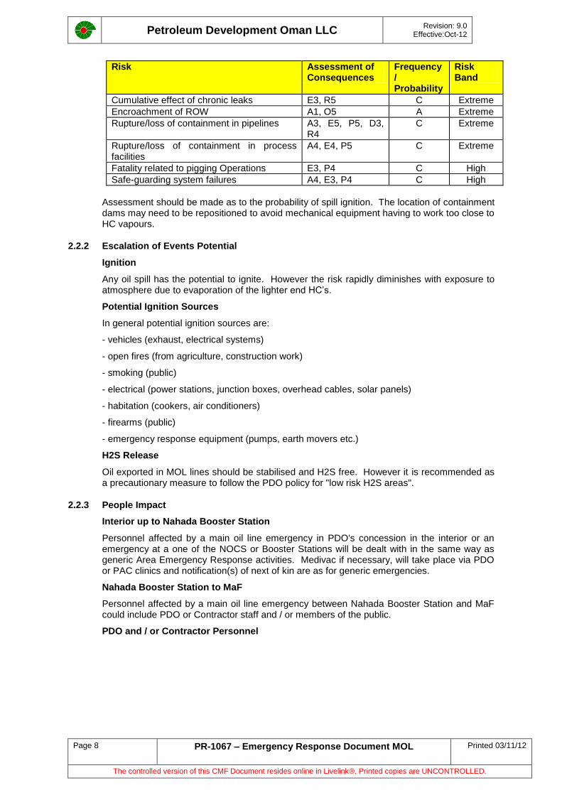
The table below illustrates identified risks associated with MOL operation from Marmul & Lekhwair/Yibal/Fahud via High Point to MaF Terminal. Consequences/Risks are as per the Risk Matrix detailed in CP-131 PDO’s Risk Management Code of Practice.
Petroleum Development Oman LLC
Revision: 9.0 Effective:Oct-12
Page 8 PR-1067 – Emergency Response Document MOL Printed 03/11/12
The controlled version of this CMF Document resides online in Livelink®. Printed copies are UNCONTROLLED.
Risk Assessment of Consequences
Frequency/ Probability
Risk Band
Cumulative effect of chronic leaks E3, R5 C Extreme
Encroachment of ROW A1, O5 A Extreme
Rupture/loss of containment in pipelines A3, E5, P5, D3, R4
C Extreme
Rupture/loss of containment in process facilities
A4, E4, P5 C Extreme
Fatality related to pigging Operations E3, P4 C High
Safe-guarding system failures A4, E3, P4 C High
Assessment should be made as to the probability of spill ignition. The location of containment dams may need to be repositioned to avoid mechanical equipment having to work too close to HC vapours.
2.2.2 Escalation of Events Potential
Ignition
Any oil spill has the potential to ignite. However the risk rapidly diminishes with exposure to atmosphere due to evaporation of the lighter end HC’s.
Potential Ignition Sources
In general potential ignition sources are:
- vehicles (exhaust, electrical systems)
- open fires (from agriculture, construction work)
- smoking (public)
- electrical (power stations, junction boxes, overhead cables, solar panels)
- habitation (cookers, air conditioners)
- firearms (public)
- emergency response equipment (pumps, earth movers etc.)
H2S Release
Oil exported in MOL lines should be stabilised and H2S free. However it is recommended as a precautionary measure to follow the PDO policy for "low risk H2S areas".
2.2.3 People Impact
Interior up to Nahada Booster Station
Personnel affected by a main oil line emergency in PDO's concession in the interior or an emergency at a one of the NOCS or Booster Stations will be dealt with in the same way as generic Area Emergency Response activities. Medivac if necessary, will take place via PDO or PAC clinics and notification(s) of next of kin are as for generic emergencies.
Nahada Booster Station to MaF
Personnel affected by a main oil line emergency between Nahada Booster Station and MaF could include PDO or Contractor staff and / or members of the public.
PDO and / or Contractor Personnel
Petroleum Development Oman LLC
Revision: 9.0 Effective:Oct-12
Page 9 PR-1067 – Emergency Response Document MOL Printed 03/11/12
The controlled version of this CMF Document resides online in Livelink®. Printed copies are UNCONTROLLED.
Because of the emergency location, it is probable that the first medical emergency services on site will be those of the government. Casualty management will in large part be taken out of the hands of PDO. Casualties will be taken to the nearest government hospital but may, if injuries dictate, be sent to specialist hospitals [e.g. Khoula in the event of burns].
Attention must be given to the tracking casualties, which hospitals they have been dispatched to and their subsequent treatment. PDO medical and H.R resources must be mobilised to interface with government hospitals and facilitate the visits of NoK or PDO management.
Public
It is likely that an oil spill or fire will attract public attention. Isolation of the emergency area and exclusion of the public to a safe distance will be an early consideration.
Though unlikely, members of public injured as a result of emergencies on the MOL also need to be addressed by the company. PDO reputation management will be facilitated through the visits of H.R and / or management to affected third party casualties. Consideration should be given by management to interim hardship payments and possible subsequent compensation however this will be addressed by the CECC team.
2.2.4 Environmental Impact
Environmental Sensitivity
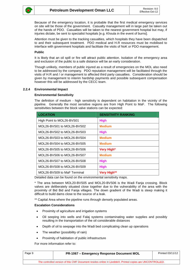
The definition of medium - high sensitivity is dependent on habitation in the vicinity of the pipeline. Generally the most sensitive regions are from High Point to MaF. The following sensitivities between the block valve stations can be expected:
LOCATION SENSITIVITY RANKING
High Point to MOL26-BVS01 High
MOL26-BVS01 to MOL26-BVS02 Medium
MOL26-BVS02 to MOL26-BVS03 High
MOL26-BVS03 to MOL26-BVS04 Medium
MOL26-BVS04 to MOL26-BVS05 Medium
MOL26-BVS05 to MOL26-BVS06 Very High*
MOL26-BVS06 to MOL26-BVS07 Medium
MOL26-BVS07 to MOL26-BVS08 High
MOL26-BVS08 to MOL26-BVS09 High
MOL26-BVS09 to MaF Terminal Very High**
Detailed data can be found on the environmental sensitivity maps.
* The area between MOL20-BVS05 and MOL20-BVS06 is the Wadi Fanja crossing. Block valves are deliberately situated close together due to the vulnerability of the area with the proximity of Bid Bid and Fanja villages. The down gradient of the Wadi is steep making it difficult to build dams close to the source of a leak.
** Capital Area where the pipeline runs through densely populated areas.
Escalation Considerations
Proximity of agriculture and irrigation systems
Oil seeping into wells and Falaj systems contaminating water supplies and possibly resulting in the transportation of the oil considerable distances
Depth of oil to seepage into the Wadi bed complicating clean up operations
The weather (possibility of rain)
Proximity of habitation of public infrastructure
For more information refer to:
Petroleum Development Oman LLC
Revision: 9.0 Effective:Oct-12
Page 10 PR-1067 – Emergency Response Document MOL Printed 03/11/12
The controlled version of this CMF Document resides online in Livelink®. Printed copies are UNCONTROLLED.
Site Protection - CP126
Clean Up and Waste Disposal - PR-1084
With the use of the sensitivity maps it should be possible to determine the location of dams, to contain any oil spilled, the On Scene Commander (OSC) can be advised where to deploy the earth moving equipment on arrival at the scene.
Containment
In 2007/2008 bundwalls have been built at all 38” MOL-25 BVS’s. (Exception is BVS-2 which is ongoing at time of print). These bundwalls will contain a limited amount of initial spill.
If escalation continues once personnel arrive at site then drainage channels should be cut from the leak site to specially constructed pits or bunded containment areas away from the immediate area of the leak. These areas should be at least 50 metres away from any habitation. Spilled oil can then be collected in a safe and controlled manner and taken to disposal points where tanker off-loading facilities exist.
Care should be taken that bunds and / or drainage channels are constructed to prevent spilled oil from flowing onto adjacent private property, roads, facilities, etc. (detailed topographical maps of the Nahada to MaF pipeline route are provided in the MaF Coastal LECC).
Should the topography of the leak site area prevent the natural drainage of spilled oil away from the leak site, then vacuum trucks or pumping equipment must be used to pump the oil away to the prepared containment areas.
2.2.5 Asset Impact
Emergency recovery should be an early consideration in emergencies affecting the MOL. Some redundancy exists in that NOCS and Booster stations can be bypassed, enabling limited functionality of the MOL pending full recovery processes being implemented. However in many areas there is no redundancy. Repairs teams and spares / replacement spool pieces and engineering equipment should be located and placed on standby at an early stage.
The CECC should immediately mobilise a support team of pipeline engineers / technically competent personnel to address recovery issues leaving the LEBC to deal with containment of the emergency.
Gas from nearby or adjacent gas lines are a major hazard, and during an emergency should be carefully considered.
Sahma Booster Station is still powered by fuel gas and in many areas of the MOL pipeline from Fahud to MaF the Oman Gas Company pipelines are in close proximity to the oil pipeline.
Response to emergencies in booster stations must be with special consideration to the escalation hazard that this fuel gas presents
The presence of heavy engineering equipment responding to an emergency and in close proximity to gas lines presents an additional hazard that must be controlled
Sahma Booster Station also contains a "Flow Measuring and Meter Proving Skid" owned and operated by a third party. This is used for fiscal purposes to measure that company's crude export from the Petrogas Sahma Field, which joins the MOL at Sahma Booster Station.
For emergencies involving Sahma booster station, Petrogas must be informed. Marmul CCR has the contact numbers and these can be referenced in Appendix B
2.2.6 Reputation Impact
Reputation management will become an issue in the event of emergencies on the export line from Nahada to MaF. Any emergency, particularly in the event of fire has a high probability of attracting public attention. The following may be expected:
Roads blocked with public vehicles
Difficulty of access for emergency vehicles
Petroleum Development Oman LLC
Revision: 9.0 Effective:Oct-12
Page 11 PR-1067 – Emergency Response Document MOL Printed 03/11/12
The controlled version of this CMF Document resides online in Livelink®. Printed copies are UNCONTROLLED.
Public approaching too close to the emergency site
On Scene Commander distracted by angry or curious members of the public
Presence of the media at the emergency scene
The responsibility for reputation management lies with the CECC however, at the emergency site it is important that the PDO OSC establishes the company as caring and responsible. The LEBC must implement a number of supporting actions:
Inform the DD of the likelihood of media and public presence
Advise mobilisation of external affairs and H.R representatives to the scene to support the OSC
Confirm the OSC has the Press Centre and Personnel Team telephone numbers
Mobilise MSE/2 expertise to evaluate the risk of contamination to water courses or other vegetation / habitation
Notify PDO medical to coordinate with government medical services to track PDO, Contractor and / or third party casualties
Hand over all reputation management issues to the CECC as soon as reasonably practical.
2.3 MOL Export Pumps
MOL export pumps within production facilities are not covered in this contingency plan as they are integral to the production facilities and are addressed in:
Part III, Contingency Plan, Production Operations Vol 3 : PR 1066
2.4 MOL Pipeline Emergencies
The responsible party(s) for emergency response for the MOL Asset(s) in the Northern and Southern Oil Directorates Area are the LEBC's in Fahud, Yibal, Lekhwair, Marmul, Nimr, Bahja and Qarn Alam.
The responsible party for emergency response for the MOL Asset(s) from High Point to MaF is the Coastal Duty LEBC.
Generic actions to be taken for emergencies involving MOL Assets are contained in:
Part II, Company Procedure : PR1065
Part III, Contingency Plan, Production Operations Vol 3 : PR1066
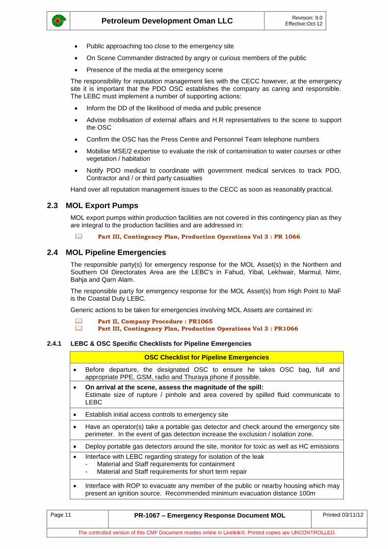
2.4.1 LEBC & OSC Specific Checklists for Pipeline Emergencies
OSC Checklist for Pipeline Emergencies
Before departure, the designated OSC to ensure he takes OSC bag, full and appropriate PPE, GSM, radio and Thuraya phone if possible.
On arrival at the scene, assess the magnitude of the spill: Estimate size of rupture / pinhole and area covered by spilled fluid communicate to LEBC
Establish initial access controls to emergency site
Have an operator(s) take a portable gas detector and check around the emergency site perimeter. In the event of gas detection increase the exclusion / isolation zone.
Deploy portable gas detectors around the site, monitor for toxic as well as HC emissions
Interface with LEBC regarding strategy for isolation of the leak - Material and Staff requirements for containment - Material and Staff requirements for short term repair
Interface with ROP to evacuate any member of the public or nearby housing which may present an ignition source. Recommended minimum evacuation distance 100m
Petroleum Development Oman LLC
Revision: 9.0 Effective:Oct-12
Page 12 PR-1067 – Emergency Response Document MOL Printed 03/11/12
The controlled version of this CMF Document resides online in Livelink®. Printed copies are UNCONTROLLED.
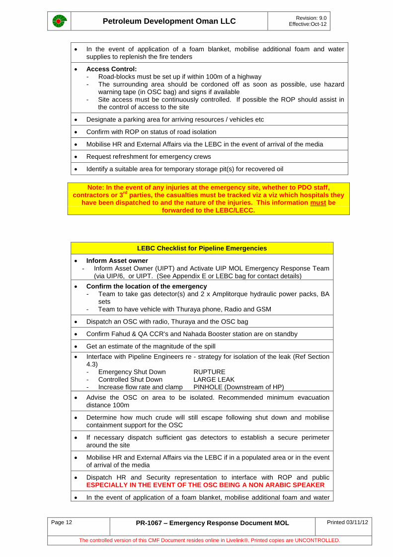
In the event of application of a foam blanket, mobilise additional foam and water supplies to replenish the fire tenders
Access Control: - Road-blocks must be set up if within 100m of a highway - The surrounding area should be cordoned off as soon as possible, use hazard
warning tape (in OSC bag) and signs if available - Site access must be continuously controlled. If possible the ROP should assist in
the control of access to the site
Designate a parking area for arriving resources / vehicles etc
Confirm with ROP on status of road isolation
Mobilise HR and External Affairs via the LEBC in the event of arrival of the media
Request refreshment for emergency crews
Identify a suitable area for temporary storage pit(s) for recovered oil
Note: In the event of any injuries at the emergency site, whether to PDO staff, contractors or 3
rd parties, the casualties must be tracked viz a viz which hospitals they
have been dispatched to and the nature of the injuries. This information must be forwarded to the LEBC/LECC.
LEBC Checklist for Pipeline Emergencies
Inform Asset owner - Inform Asset Owner (UIPT) and Activate UIP MOL Emergency Response Team
(via UIP/6, or UIPT. (See Appendix E or LEBC bag for contact details)
Confirm the location of the emergency - Team to take gas detector(s) and 2 x Amplitorque hydraulic power packs, BA
sets - Team to have vehicle with Thuraya phone, Radio and GSM
Dispatch an OSC with radio, Thuraya and the OSC bag
Confirm Fahud & QA CCR's and Nahada Booster station are on standby
Get an estimate of the magnitude of the spill
Interface with Pipeline Engineers re - strategy for isolation of the leak (Ref Section 4.3) - Emergency Shut Down RUPTURE - Controlled Shut Down LARGE LEAK - Increase flow rate and clamp PINHOLE (Downstream of HP)
Advise the OSC on area to be isolated. Recommended minimum evacuation distance 100m
Determine how much crude will still escape following shut down and mobilise containment support for the OSC
If necessary dispatch sufficient gas detectors to establish a secure perimeter around the site
Mobilise HR and External Affairs via the LEBC if in a populated area or in the event of arrival of the media
Dispatch HR and Security representation to interface with ROP and public ESPECIALLY IN THE EVENT OF THE OSC BEING A NON ARABIC SPEAKER
In the event of application of a foam blanket, mobilise additional foam and water
Petroleum Development Oman LLC
Revision: 9.0 Effective:Oct-12
Page 13 PR-1067 – Emergency Response Document MOL Printed 03/11/12
The controlled version of this CMF Document resides online in Livelink®. Printed copies are UNCONTROLLED.
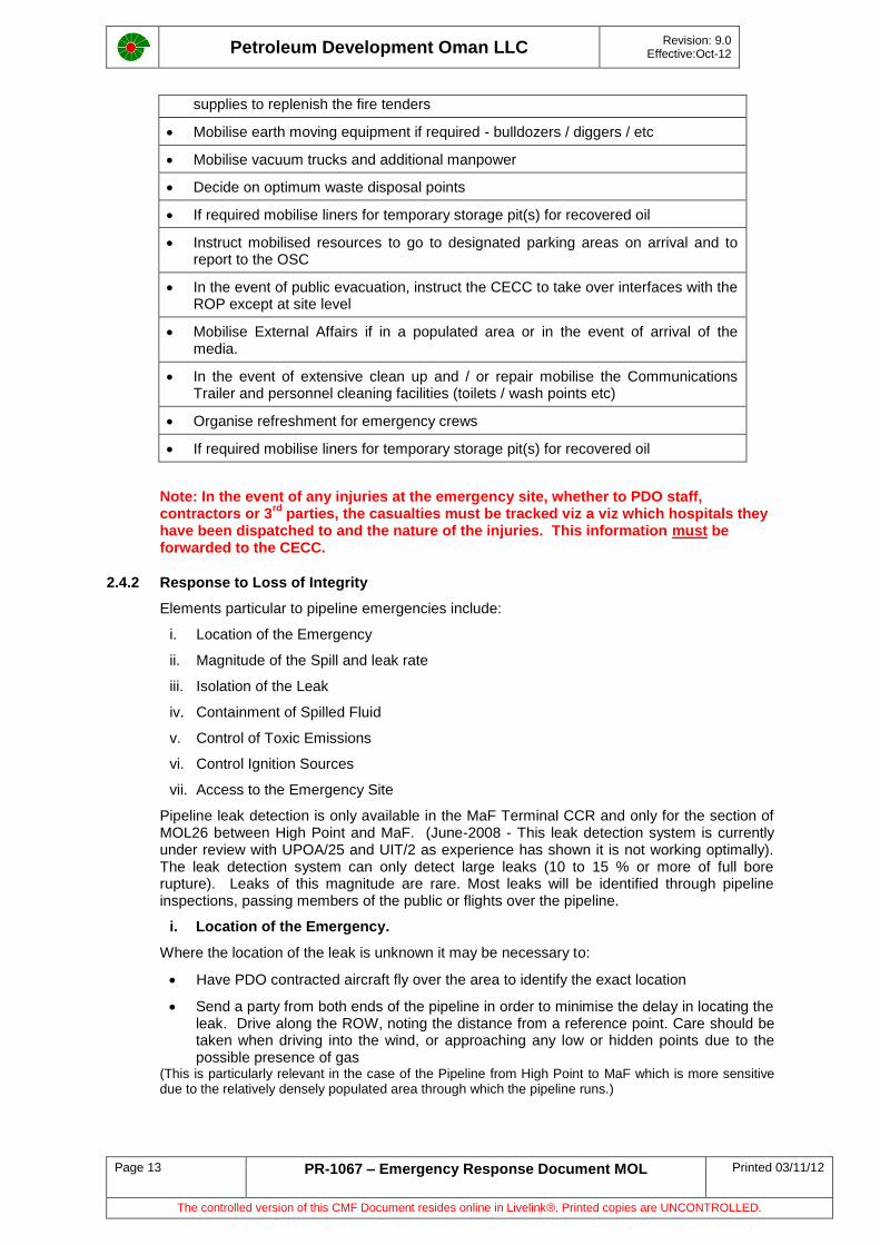
supplies to replenish the fire tenders
Mobilise earth moving equipment if required - bulldozers / diggers / etc
Mobilise vacuum trucks and additional manpower
Decide on optimum waste disposal points
If required mobilise liners for temporary storage pit(s) for recovered oil
Instruct mobilised resources to go to designated parking areas on arrival and to report to the OSC
In the event of public evacuation, instruct the CECC to take over interfaces with the ROP except at site level
Mobilise External Affairs if in a populated area or in the event of arrival of the media.
In the event of extensive clean up and / or repair mobilise the Communications Trailer and personnel cleaning facilities (toilets / wash points etc)
Organise refreshment for emergency crews
If required mobilise liners for temporary storage pit(s) for recovered oil
Note: In the event of any injuries at the emergency site, whether to PDO staff, contractors or 3
rd parties, the casualties must be tracked viz a viz which hospitals they
have been dispatched to and the nature of the injuries. This information must be forwarded to the CECC.
2.4.2 Response to Loss of Integrity
Elements particular to pipeline emergencies include:
i. Location of the Emergency
ii. Magnitude of the Spill and leak rate
iii. Isolation of the Leak
iv. Containment of Spilled Fluid
v. Control of Toxic Emissions
vi. Control Ignition Sources
vii. Access to the Emergency Site
Pipeline leak detection is only available in the MaF Terminal CCR and only for the section of MOL26 between High Point and MaF. (June-2008 - This leak detection system is currently under review with UPOA/25 and UIT/2 as experience has shown it is not working optimally). The leak detection system can only detect large leaks (10 to 15 % or more of full bore rupture). Leaks of this magnitude are rare. Most leaks will be identified through pipeline inspections, passing members of the public or flights over the pipeline.
i. Location of the Emergency.
Where the location of the leak is unknown it may be necessary to:
Have PDO contracted aircraft fly over the area to identify the exact location
Send a party from both ends of the pipeline in order to minimise the delay in locating the leak. Drive along the ROW, noting the distance from a reference point. Care should be taken when driving into the wind, or approaching any low or hidden points due to the possible presence of gas
(This is particularly relevant in the case of the Pipeline from High Point to MaF which is more sensitive due to the relatively densely populated area through which the pipeline runs.)
Petroleum Development Oman LLC
Revision: 9.0 Effective:Oct-12
Page 14 PR-1067 – Emergency Response Document MOL Printed 03/11/12
The controlled version of this CMF Document resides online in Livelink®. Printed copies are UNCONTROLLED.
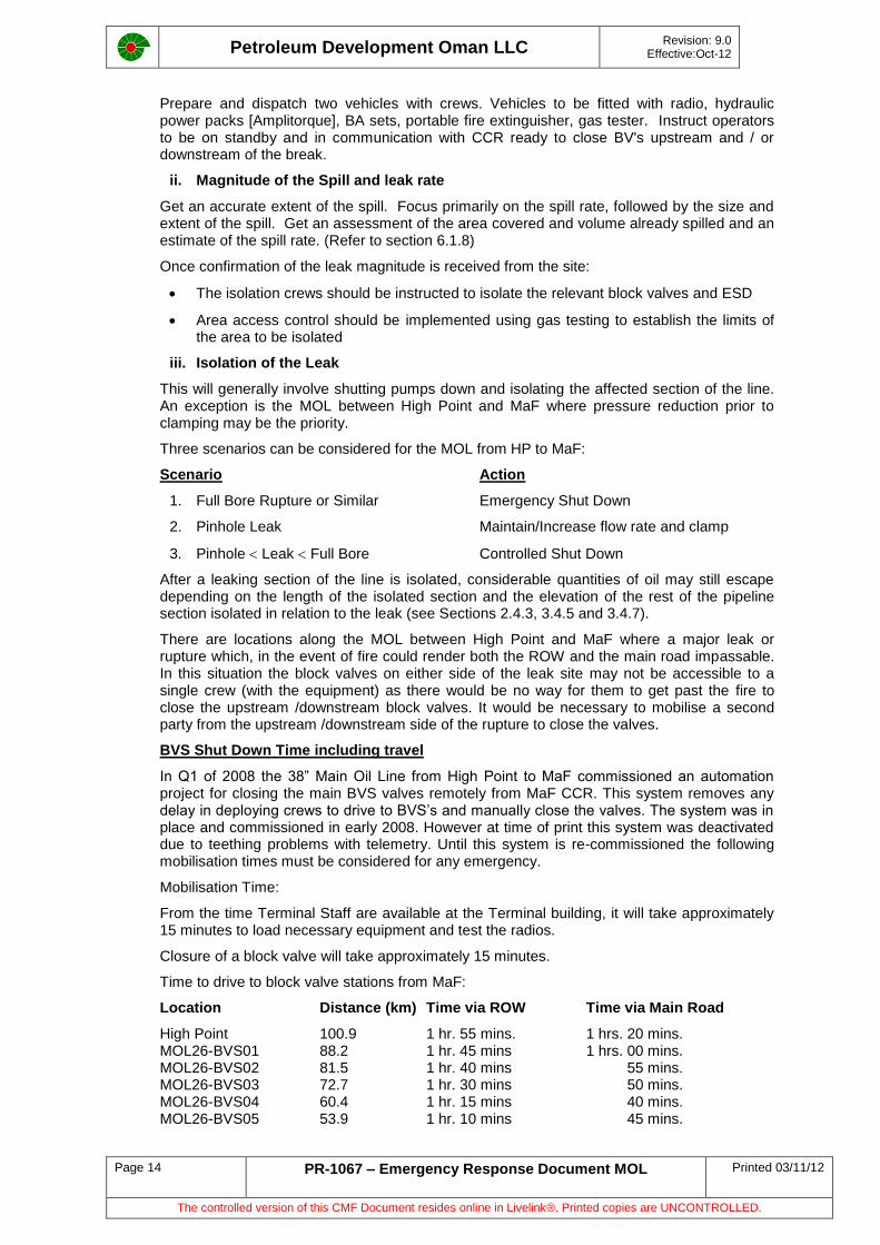
Prepare and dispatch two vehicles with crews. Vehicles to be fitted with radio, hydraulic power packs [Amplitorque], BA sets, portable fire extinguisher, gas tester. Instruct operators to be on standby and in communication with CCR ready to close BV's upstream and / or downstream of the break.
ii. Magnitude of the Spill and leak rate
Get an accurate extent of the spill. Focus primarily on the spill rate, followed by the size and extent of the spill. Get an assessment of the area covered and volume already spilled and an estimate of the spill rate. (Refer to section 6.1.8)
Once confirmation of the leak magnitude is received from the site:
The isolation crews should be instructed to isolate the relevant block valves and ESD
Area access control should be implemented using gas testing to establish the limits of the area to be isolated
iii. Isolation of the Leak
This will generally involve shutting pumps down and isolating the affected section of the line. An exception is the MOL between High Point and MaF where pressure reduction prior to clamping may be the priority.
Three scenarios can be considered for the MOL from HP to MaF:
Scenario Action
1. Full Bore Rupture or Similar Emergency Shut Down
2. Pinhole Leak Maintain/Increase flow rate and clamp
3. Pinhole Leak Full Bore Controlled Shut Down
After a leaking section of the line is isolated, considerable quantities of oil may still escape depending on the length of the isolated section and the elevation of the rest of the pipeline section isolated in relation to the leak (see Sections 2.4.3, 3.4.5 and 3.4.7).
There are locations along the MOL between High Point and MaF where a major leak or rupture which, in the event of fire could render both the ROW and the main road impassable. In this situation the block valves on either side of the leak site may not be accessible to a single crew (with the equipment) as there would be no way for them to get past the fire to close the upstream /downstream block valves. It would be necessary to mobilise a second party from the upstream /downstream side of the rupture to close the valves.
BVS Shut Down Time including travel
In Q1 of 2008 the 38” Main Oil Line from High Point to MaF commissioned an automation project for closing the main BVS valves remotely from MaF CCR. This system removes any delay in deploying crews to drive to BVS’s and manually close the valves. The system was in place and commissioned in early 2008. However at time of print this system was deactivated due to teething problems with telemetry. Until this system is re-commissioned the following mobilisation times must be considered for any emergency.
Mobilisation Time:
From the time Terminal Staff are available at the Terminal building, it will take approximately 15 minutes to load necessary equipment and test the radios.
Closure of a block valve will take approximately 15 minutes.
Time to drive to block valve stations from MaF:
Location Distance (km) Time via ROW Time via Main Road
High Point 100.9 1 hr. 55 mins. 1 hrs. 20 mins. MOL26-BVS01 88.2 1 hr. 45 mins 1 hrs. 00 mins. MOL26-BVS02 81.5 1 hr. 40 mins 55 mins. MOL26-BVS03 72.7 1 hr. 30 mins 50 mins. MOL26-BVS04 60.4 1 hr. 15 mins 40 mins. MOL26-BVS05 53.9 1 hr. 10 mins 45 mins.
Petroleum Development Oman LLC
Revision: 9.0 Effective:Oct-12
Page 15 PR-1067 – Emergency Response Document MOL Printed 03/11/12
The controlled version of this CMF Document resides online in Livelink®. Printed copies are UNCONTROLLED.
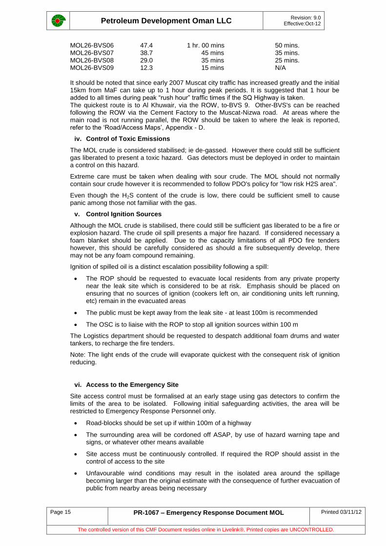
MOL26-BVS06 47.4 1 hr. 00 mins 50 mins. MOL26-BVS07 38.7 45 mins 35 mins. MOL26-BVS08 29.0 35 mins 25 mins. MOL26-BVS09 12.3 15 mins N/A It should be noted that since early 2007 Muscat city traffic has increased greatly and the initial 15km from MaF can take up to 1 hour during peak periods. It is suggested that 1 hour be added to all times during peak “rush hour” traffic times if the SQ Highway is taken. The quickest route is to Al Khuwair, via the ROW, to-BVS 9. Other-BVS's can be reached following the ROW via the Cement Factory to the Muscat-Nizwa road. At areas where the main road is not running parallel, the ROW should be taken to where the leak is reported, refer to the ‘Road/Access Maps’, Appendix - D.
iv. Control of Toxic Emissions
The MOL crude is considered stabilised; ie de-gassed. However there could still be sufficient gas liberated to present a toxic hazard. Gas detectors must be deployed in order to maintain a control on this hazard.
Extreme care must be taken when dealing with sour crude. The MOL should not normally contain sour crude however it is recommended to follow PDO's policy for "low risk H2S area".
Even though the H2S content of the crude is low, there could be sufficient smell to cause panic among those not familiar with the gas.
v. Control Ignition Sources
Although the MOL crude is stabilised, there could still be sufficient gas liberated to be a fire or explosion hazard. The crude oil spill presents a major fire hazard. If considered necessary a foam blanket should be applied. Due to the capacity limitations of all PDO fire tenders however, this should be carefully considered as should a fire subsequently develop, there may not be any foam compound remaining.
Ignition of spilled oil is a distinct escalation possibility following a spill:
The ROP should be requested to evacuate local residents from any private property near the leak site which is considered to be at risk. Emphasis should be placed on ensuring that no sources of ignition (cookers left on, air conditioning units left running, etc) remain in the evacuated areas
The public must be kept away from the leak site - at least 100m is recommended
The OSC is to liaise with the ROP to stop all ignition sources within 100 m
The Logistics department should be requested to despatch additional foam drums and water tankers, to recharge the fire tenders.
Note: The light ends of the crude will evaporate quickest with the consequent risk of ignition reducing.
vi. Access to the Emergency Site
Site access control must be formalised at an early stage using gas detectors to confirm the limits of the area to be isolated. Following initial safeguarding activities, the area will be restricted to Emergency Response Personnel only.
Road-blocks should be set up if within 100m of a highway
The surrounding area will be cordoned off ASAP, by use of hazard warning tape and signs, or whatever other means available
Site access must be continuously controlled. If required the ROP should assist in the control of access to the site
Unfavourable wind conditions may result in the isolated area around the spillage becoming larger than the original estimate with the consequence of further evacuation of public from nearby areas being necessary
Petroleum Development Oman LLC
Revision: 9.0 Effective:Oct-12
Page 16 PR-1067 – Emergency Response Document MOL Printed 03/11/12
The controlled version of this CMF Document resides online in Livelink®. Printed copies are UNCONTROLLED.
Reception of Emergency Equipment to the scene:
Roads leading to the emergency site are likely to be blocked if no corrective action is taken at an early stage by the ROP, this can result in long delays for equipment to reach the scene. Early involvement of the ROP can ensure mobilised equipment and manpower have unhindered access. ROP should be informed what equipment is underway and if necessary, be requested to provide police escort
Effective planning can avoid congestion at the scene with a lot of equipment and manpower arriving at the same time. The OSC should be made aware of equipment underway so he can make provisions at an early stage
Initially it is not necessary to bring in too much equipment as construction of containment areas will be the prime concern
Equipment which is not used should be parked at a designated area by the OSC
Other Actions to be considered by LEBC
Despatch the Emergency Radio Caravan (ERC) from Telecoms to the spill location
- The ERC is a well equipped communication centre with various long/short range and air to ground radio's, fax and telephone links to the coast
- The MOL from High Point to MaF runs through mountainous terrain and there is a small possibility of blind spots with the communication equipment
- The functionality of the ERC should be checked before a final site is selected
Start mobilising or place on stand by, earth moving equipment at an early stage
Use Pipeline Sensitivity maps, to evaluate potential risk to third parties
If the leak site is in an populated area, the Security team member on duty should contact the ROP and request assistance in evacuating the public from any area that is (or could be) threatened
Dispatch the pipeline emergency response equipment container containing, PPE, scaffolding, lights etc. The container is located in the supply yard in MaF.
The Human Resource team member to interface with the local Wali if the local population is impacted, and in the event of evacuation or a necessity for the public to be kept away from the emergency site, should seek his cooperation and agreement
Special flights may be required to bring in additional resources and manpower. Identification of the nearest suitable airstrip, and possibly an inspection should be arranged.
Dispatch the emergency equipment container. This container should contain equipments such as PPE, spades, torches, etc…, witch are essential for a pipe line leak repair.
Petroleum Development Oman LLC
Revision: 9.0 Effective:Oct-12
Page 17 PR-1067 – Emergency Response Document MOL Printed 03/11/12
The controlled version of this CMF Document resides online in Livelink®. Printed copies are UNCONTROLLED.
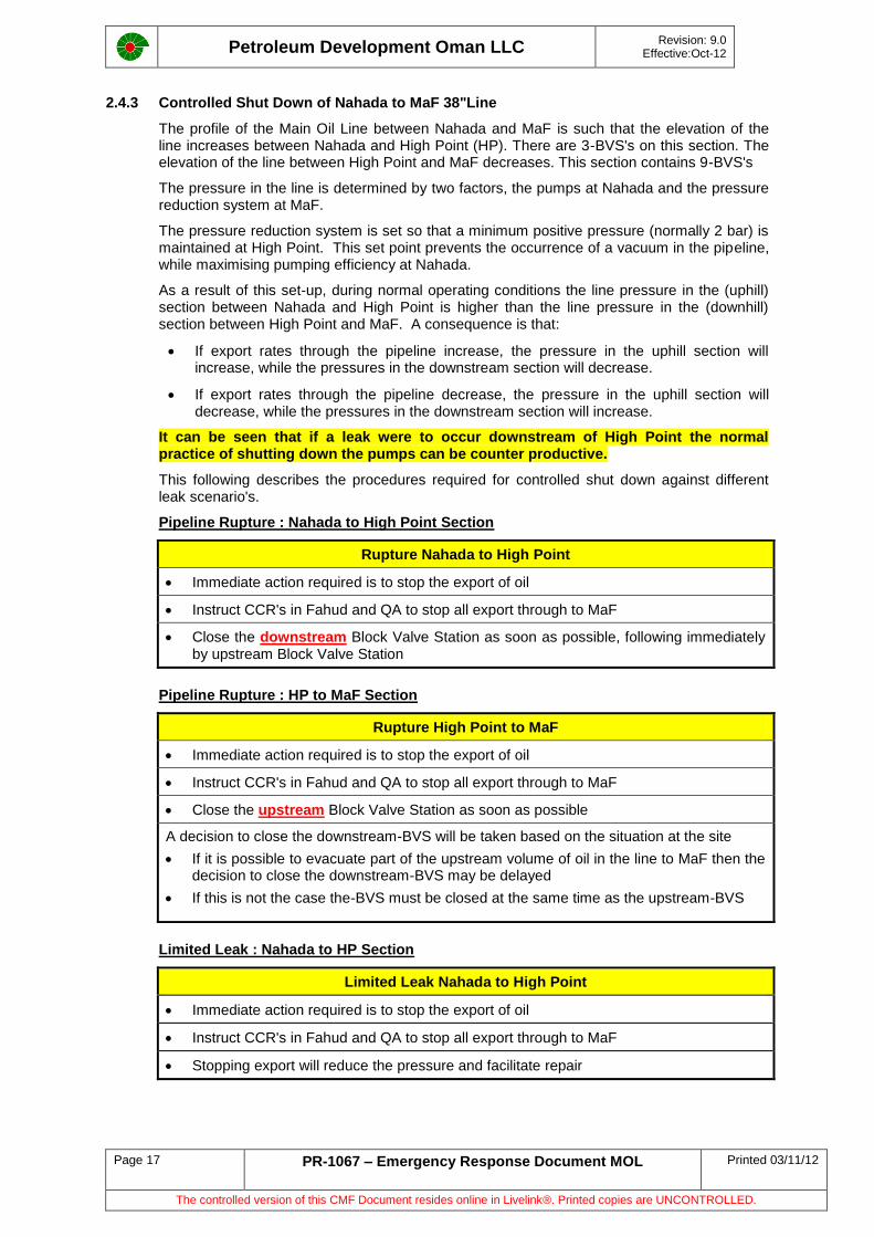
2.4.3 Controlled Shut Down of Nahada to MaF 38"Line
The profile of the Main Oil Line between Nahada and MaF is such that the elevation of the line increases between Nahada and High Point (HP). There are 3-BVS's on this section. The elevation of the line between High Point and MaF decreases. This section contains 9-BVS's
The pressure in the line is determined by two factors, the pumps at Nahada and the pressure reduction system at MaF.
The pressure reduction system is set so that a minimum positive pressure (normally 2 bar) is maintained at High Point. This set point prevents the occurrence of a vacuum in the pipeline, while maximising pumping efficiency at Nahada.
As a result of this set-up, during normal operating conditions the line pressure in the (uphill) section between Nahada and High Point is higher than the line pressure in the (downhill) section between High Point and MaF. A consequence is that:
If export rates through the pipeline increase, the pressure in the uphill section will increase, while the pressures in the downstream section will decrease.
If export rates through the pipeline decrease, the pressure in the uphill section will decrease, while the pressures in the downstream section will increase.
It can be seen that if a leak were to occur downstream of High Point the normal practice of shutting down the pumps can be counter productive.
This following describes the procedures required for controlled shut down against different leak scenario's.
Pipeline Rupture : Nahada to High Point Section
Rupture Nahada to High Point
Immediate action required is to stop the export of oil
Instruct CCR's in Fahud and QA to stop all export through to MaF
Close the downstream Block Valve Station as soon as possible, following immediately by upstream Block Valve Station
Pipeline Rupture : HP to MaF Section
Rupture High Point to MaF
Immediate action required is to stop the export of oil
Instruct CCR's in Fahud and QA to stop all export through to MaF
Close the upstream Block Valve Station as soon as possible
A decision to close the downstream-BVS will be taken based on the situation at the site
If it is possible to evacuate part of the upstream volume of oil in the line to MaF then the decision to close the downstream-BVS may be delayed
If this is not the case the-BVS must be closed at the same time as the upstream-BVS
Limited Leak : Nahada to HP Section
Limited Leak Nahada to High Point
Immediate action required is to stop the export of oil
Instruct CCR's in Fahud and QA to stop all export through to MaF
Stopping export will reduce the pressure and facilitate repair
Petroleum Development Oman LLC
Revision: 9.0 Effective:Oct-12
Page 18 PR-1067 – Emergency Response Document MOL Printed 03/11/12
The controlled version of this CMF Document resides online in Livelink®. Printed copies are UNCONTROLLED.
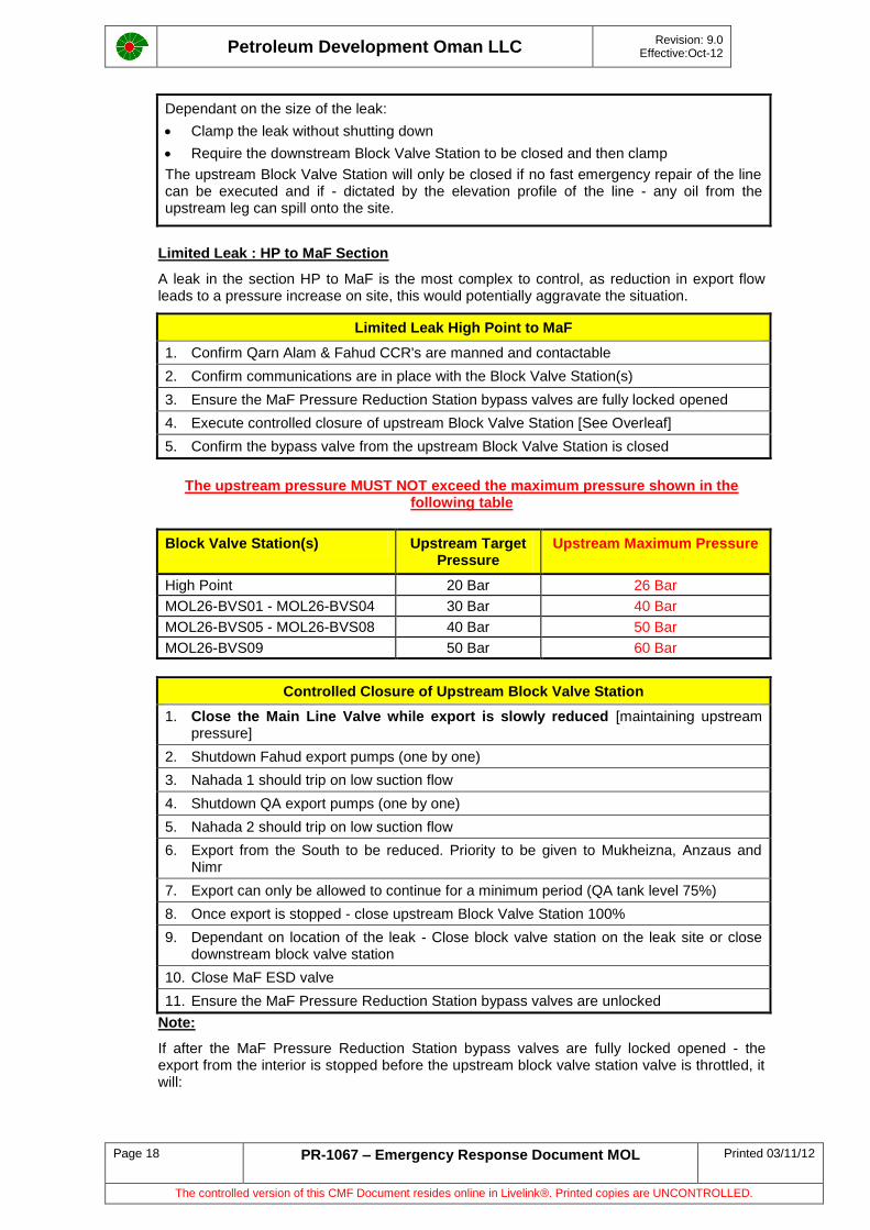
Dependant on the size of the leak:
Clamp the leak without shutting down
Require the downstream Block Valve Station to be closed and then clamp
The upstream Block Valve Station will only be closed if no fast emergency repair of the line can be executed and if - dictated by the elevation profile of the line - any oil from the upstream leg can spill onto the site.
Limited Leak : HP to MaF Section
A leak in the section HP to MaF is the most complex to control, as reduction in export flow leads to a pressure increase on site, this would potentially aggravate the situation.
Limited Leak High Point to MaF
1. Confirm Qarn Alam & Fahud CCR's are manned and contactable
2. Confirm communications are in place with the Block Valve Station(s)
3. Ensure the MaF Pressure Reduction Station bypass valves are fully locked opened
4. Execute controlled closure of upstream Block Valve Station [See Overleaf]
5. Confirm the bypass valve from the upstream Block Valve Station is closed
The upstream pressure MUST NOT exceed the maximum pressure shown in the following table
Block Valve Station(s) Upstream Target Pressure
Upstream Maximum Pressure
High Point 20 Bar 26 Bar
MOL26-BVS01 - MOL26-BVS04 30 Bar 40 Bar
MOL26-BVS05 - MOL26-BVS08 40 Bar 50 Bar
MOL26-BVS09 50 Bar 60 Bar
Controlled Closure of Upstream Block Valve Station
1. Close the Main Line Valve while export is slowly reduced [maintaining upstream pressure]
2. Shutdown Fahud export pumps (one by one)
3. Nahada 1 should trip on low suction flow
4. Shutdown QA export pumps (one by one)
5. Nahada 2 should trip on low suction flow
6. Export from the South to be reduced. Priority to be given to Mukheizna, Anzaus and Nimr
7. Export can only be allowed to continue for a minimum period (QA tank level 75%)
8. Once export is stopped - close upstream Block Valve Station 100%
9. Dependant on location of the leak - Close block valve station on the leak site or close downstream block valve station
10. Close MaF ESD valve
11. Ensure the MaF Pressure Reduction Station bypass valves are unlocked
Note:
If after the MaF Pressure Reduction Station bypass valves are fully locked opened - the export from the interior is stopped before the upstream block valve station valve is throttled, it will:
Petroleum Development Oman LLC
Revision: 9.0 Effective:Oct-12
Page 19 PR-1067 – Emergency Response Document MOL Printed 03/11/12
The controlled version of this CMF Document resides online in Livelink®. Printed copies are UNCONTROLLED.
not lead to a pressure increase at the affected Block Valve Station, however it will lead to
a vacuum in the pipeline system, starting at highpoint, which will progressively extend towards MaF.
It is therefore important to close any upstream-BVS as soon as possible to minimise the vacuum in the line.
2.5 NOCS and Booster Stations
Emergency response in the North Oman Crude Stabilisation Unit and MOL Booster Stations is managed by the Production Coordinators and is a generic response. The same response is applied to any HC processing plant. There are no specific considerations in the response for the emergency teams other than those outlined in Emergency Response Documents Part III, Contingency Plan Vol 3, Production Operations.
Part III, Contingency Plan, Production Operations Vol 3 : PR 1066

Petroleum Development Oman LLC
Revision: 9.0 Effective:Oct-12
Page 20 PR-1067 – Emergency Response Document MOL Printed 03/11/12
The controlled version of this CMF Document resides online in Livelink®. Printed copies are UNCONTROLLED.
Petroleum Development Oman LLC
Revision: 9.0 Effective:Oct-12
Page 21 PR-1067 – Emergency Response Document MOL Printed 03/11/12
The controlled version of this CMF Document resides online in Livelink®. Printed copies are UNCONTROLLED.
3 Asset Description.
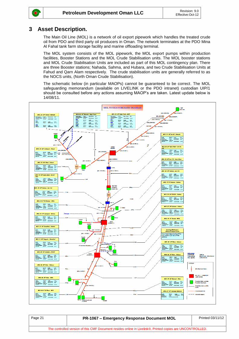
The Main Oil Line (MOL) is a network of oil export pipework which handles the treated crude oil from PDO and third party oil producers in Oman. The network terminates at the PDO Mina Al Fahal tank farm storage facility and marine offloading terminal.
The MOL system consists of the MOL pipework, the MOL export pumps within production facilities, Booster Stations and the MOL Crude Stabilisation units. The MOL booster stations and MOL Crude Stabilisation Units are included as part of this MOL contingency plan. There are three Booster stations; Nahada, Sahma, and Hubara, and two Crude Stabilisation Units at Fahud and Qarn Alam respectively. The crude stabilisation units are generally referred to as the NOCS units, (North Oman Crude Stabilisation).
The schematic below (in particular MAOPs) cannot be guaranteed to be correct. The MOL safeguarding memorandum (available on LIVELINK or the PDO intranet) custodian UIP/1 should be consulted before any actions assuming MAOP’s are taken. Latest update below is 14/08/11.
Petroleum Development Oman LLC
Revision: 9.0 Effective:Oct-12
Page 22 PR-1067 – Emergency Response Document MOL Printed 03/11/12
The controlled version of this CMF Document resides online in Livelink®. Printed copies are UNCONTROLLED.
3.1 Pipelines
3.1.1 Northern Section to High Point
In the North, the MOL runs from Lekhwair and from Yibal to Fahud. These sections can be isolated and managed internally by local LEBC with little effect on downstream sections of MOL.
For inter Asset emergencies the MOL is considered to start at Fahud Main Line Pumping Station [MLPS].
This section of the MOL is a section of 76km running from Fahud MLPS to Nahada booster station followed by a 101km section from Nahada to High Point
Nahada booster station receives crude from the Northern, Central and Southern fields, combining the streams and exporting them to the coast. It consist of 2 separate stations, Nahada-1 which has four electrical booster pumps and Nahada-2 which has 5 electrical pumps.
Nahada is geographically situated at the foot of the mountain range that separates the Interior from the Coast. The height of the mountains at the "High Point" require a discharge pressure of greater than 5,000 kpa to be maintained at Nahada
As the elevation of the MOL increases after Nahada, the crude pressure reduces to near zero at the High Point. To economise on material usage the pipeline wall thickness of the MOL also reduces in parallel with the pressure. This reduction occurs at various points along the MOL and the changes are always in external dimensions only
3.1.2 High Point to MaF
A 101 km, 38" diameter pipeline transports the combined North, Central and Southern crude streams from the High Point to MaF. The pipeline has been in operation since it was commissioned in 1986.
High Point is 670 metres above sea level, the lowest elevation is at the pressure reducing station in MaF Tank Farm at 35 metres above sea level. The pressure reducing station controls the incoming fluid pressure to the upper and lower tank farms.
The line is fitted with pig launching and receiving facilities for both maintenance and inspection services. Nine block valves stations enable isolation of segments of the line for emergency repair or maintenance. The bypass of these-BVS was modified in 2003 and is above ground level. Remote actuation of the main block valves has been installed during 2008. However at the time of print this system is not 100% reliable and is presently classed as not working
The line is externally protected against corrosion with FBE coating and is continuously protected by induced cathodic protection throughout the complete length.
Emergency shutdown (ESD) can be triggered from the Terminal Control Room, when this is activated the following happens:
- The ESD valve in the Tank Farm closes and the pressure relief system will relieve the pipeline pressure to either of Tank 103 or Tank 105 in the lower tank farm
- Local visual and audible alarms in the Terminal Control room, will activate
On ESD activation, a signal will automatically be sent to the pumps at Fahud and Qarn Alam export pumping stations and Nahada Booster stations. All pumps will stop automatically on ESD. This is tested at 6 monthly intervals.
3.1.3 Marmul to Nahada Booster Station
In the South, the MOL starts at Marmul Main Production Station [MMPS].
All the Marmul area fields export to Marmul via pipelines which are covered under the Production Operations Contingency plan PR-1066. The other Southern region major area producers; Nimr, Rima and Bahja export via pipelines into the MOL at various points
Petroleum Development Oman LLC
Revision: 9.0 Effective:Oct-12
Page 23 PR-1067 – Emergency Response Document MOL Printed 03/11/12
The controlled version of this CMF Document resides online in Livelink®. Printed copies are UNCONTROLLED.
The Southern and Central section of the MOL, is a 580km section running from Marmul Main Production Station to Nahada Booster Station, via Hubara and Sahma Booster Stations, and Qarn Alam Production Station
Hubara Booster Station is geographically situated on the MOL between Nimr and Bahja, 31km from Rima
Hubara receives the MOL product from the Marmul and Nimr areas and combines it with the export stream from Rima. The combined stream is pumped to Sahma via three electrical driven pumps (2 pumps in use, one on stand-by). Hubara is part of the Bahja operating area
Sahma Booster Station is geographically situated on the MOL between the Bahja and Qarn Alam. Sahma is logistically part of the Bahja area
Sahma receives the MOL product from Marmul, Nimr and Rima areas, together with all the individual streams from the Bahja area. It also receives the export crude from third party fields, PETROGAS SAHMA field, and OXY MUKHAIZNA field. This crude is exported with the PDO product.
The total Southern export crude is pumped from Sahma via eight Ruston Gas Turbine driven booster pumps and two electrical driven pump, to Qarn Alam in Central Oman. More electrical pumps are scheduled for 2013 to replace the aging turbines.
Situated between Sahma and Qarn Alam, and part of the Central Oman oil fields, are Barik and Al Ghubar. Barik discharges it's crude oil product to Al Ghubar, which in turn exports its own and the Barik crude into the MOL15 upstream of-BVS-02
Qarn Alam is the major area of Central Oman and receives and treats the crude from the Central Oman Oil fields
The Central Oman product stream is then combined with the Southern export stream in Qarn Alam Production Station, and pumped via four electrical driven Booster pumps to Nahada Booster Station
3.2 Booster Stations
There are five Booster Stations within PDO operations which boost the pressure of crude oil in order to facilitate transfer through the MOL. Four of the m is owned by UIPT and the fifth one is owned by QA team.
The stations are designed and built to recognised engineering standards, however their age is such that significant changes have taken place in engineering standards since construction. Equipment spacing and ESD isolation, which were designed to minimise damage to adjacent equipment in the event of a fire or explosion, have changed.
As oil production has increased, each of the Booster Station has been extended with additional booster pumps. This has resulted in equipment overcrowding, particularly in control rooms.
The stations are manned during normal working hours only [07:00 to 17:00].
All of the Booster Stations pumping systems can be bypassed, allowing upstream and downstream facilities to maintain a reduced throughput.
The Booster Stations are powered with fuel gas and or electrical pumps. Sahma and Hubara have the main "South Oman Gas Line System (SOGL)" routed through them with Pigging facilities inside the station perimeter.
These gas supplies are a source of hazard, and during any emergency should be carefully considered.
Sahma Booster Station also contains a "Flow Measuring and Meter Proving Skid" owned and operated by a third party. This is used for fiscal purposes to measure that company's crude export from the Petrogas Sahma Field, which joins the MOL at Sahma Booster Station.
For any emergency involving Sahma Booster Stations, Petrogas should be informed. Marmul CCR has the contact numbers.
Petroleum Development Oman LLC
Revision: 9.0 Effective:Oct-12
Page 24 PR-1067 – Emergency Response Document MOL Printed 03/11/12
The controlled version of this CMF Document resides online in Livelink®. Printed copies are UNCONTROLLED.
3.3 Crude Stabilisation Unit
There are two MOL Crude Stabilisation Units [CSU] interlinked with the MOL system, one (Fahud) handles crude from North Oman, the other (QA) was designed to handle crude from South and Central Oman. QA NOCS is presently by-passed and not functioning as it is deemed unnecessary.
The Stabilisation Units are situated in Fahud and Qarn Alam and are referred to as NOCS (North Oman Crude Stabilisation).
Both NOCS facilities are designed for unattended operation.
Crude Stabilisation is achieved using liquid ring vacuum compressors controlling the sub-atmospheric TVP of the crude oil stream. Stabilisation is necessary to provide protection from gas build up for the floating roof storage tanks at the Tank Farm in MaF.
The CSU’s have been designed and built to recognised engineering standards. Equipment spacing, isolation and ESD are designed to minimise damage to adjacent equipment during a fire or explosion.
The Crude Stabilisation Unit in Fahud is not redundant, there is no alternative means of product stabilisation and the consequences in the event of inoperability is severe.
The Crude Stabilisation Units are capable of being bypassed, allowing upstream and downstream facilities to maintain a reduced throughput through the station bypass. Use of the CSU bypass is however, dependent on the technical integrity of the bypass following damage to other sections of the CSU. Bypass would also result in unstabilised crude being stored in MaF with consequential increase in risk.
Stabalised condensate from Central Processing Plant (CPP) at Saih Rawl is sent to the MOL through QA booster pumps. Due to the changes in the crude temperature and composition which affects TVP of the crude a project is being intiated to control the TVP of the crude at the desired limits. The project is expected to be completed in the coming five years.
3.4 Pipeline Technical Details
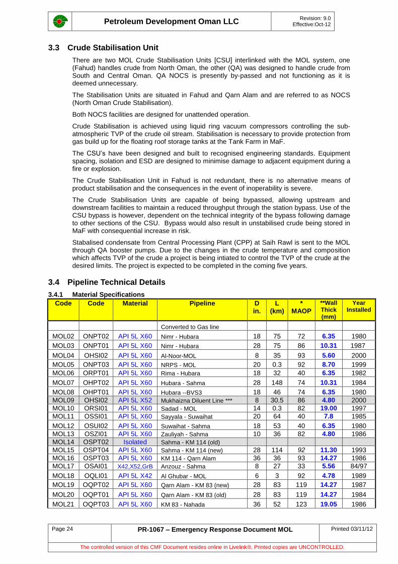
3.4.1 Material Specifications
Code Code Material Pipeline D in.
L (km)
* MAOP
**Wall Thick (mm)
Year Installed
Converted to Gas line
MOL02 ONPT02 API 5L X60 Nimr - Hubara 18 75 72 6.35 1980
MOL03 ONPT01 API 5L X60 Nimr - Hubara 28 75 86 10.31 1987
MOL04 OHSI02 API 5L X60 Al-Noor-MOL 8 35 93 5.60 2000
MOL05 ONPT03 API 5L X60 NRPS - MOL 20 0.3 92 8.70 1999
MOL06 ORPT01 API 5L X60 Rima - Hubara 18 32 40 6.35 1982
MOL07 OHPT02 API 5L X60 Hubara - Sahma 28 148 74 10.31 1984
MOL08 OHPT01 API 5L X60 Hubara --BVS3 18 46 74 6.35 1980
MOL09 OHSI02 API 5L X52 Mukhaizna Diluent Line *** 8 30.5 86 4.80 2000
MOL10 ORSI01 API 5L X60 Sadad - MOL 14 0.3 82 19.00 1997
MOL11 OSSI01 API 5L X60 Sayyala - Suwaihat 20 64 40 7.8 1985
MOL12 OSUI02 API 5L X60 Suwaihat - Sahma 18 53 40 6.35 1980
MOL13 OSZI01 API 5L X60 Zauliyah - Sahma 10 36 82 4.80 1986
MOL14 OSPT02 Isolated Sahma - KM 114 (old)
MOL15 OSPT04 API 5L X60 Sahma - KM 114 (new) 28 114 92 11.30 1993
MOL16 OSPT03 API 5L X60 KM 114 - Qarn Alam 36 36 93 14.27 1986
MOL17 OSAI01 X42,X52,GrB Anzouz - Sahma 8 27 33 5.56 84/97
MOL18 OQLI01 API 5L X42 Al Ghubar - MOL 6 3 92 4.78 1989
MOL19 OQPT02 API 5L X60 Qarn Alam - KM 83 (new) 28 83 119 14.27 1987
MOL20 OQPT01 API 5L X60 Qarn Alam - KM 83 (old) 28 83 119 14.27 1984
MOL21 OQPT03 API 5L X60 KM 83 - Nahada 36 52 123 19.05 1986
Petroleum Development Oman LLC
Revision: 9.0 Effective:Oct-12
Page 25 PR-1067 – Emergency Response Document MOL Printed 03/11/12
The controlled version of this CMF Document resides online in Livelink®. Printed copies are UNCONTROLLED.
MOL22 OYAI01 API 5L X60 Yibal - Fahud 20 58 73 7.90 1989
MOL23 OLPI01 API 5L X60 Lekhwair - Fahud MLPS 24 138 40 9.52 1986
MOL24 OFPT01 API 5L X60 Fahud - Nahada 30 76 68/55 11/9.5 1984/9
MOL25 OJPT02 API 5L X60 Nahada- High Point 3 sections 42 100 89/80/
57 10/14/
15 1984
MOL26 OJPT03 API 5L X60 High Point - MAF (2 sections) 38 101 64/78 10/12 1986
MOL27 Harweel - Marmul 18 85 92 Tbc
MOL28 OMPT03 API 5L X65 Marmul - Nimr 24 84 92 9.7 2006
MOL29 OHPT04 API 5L X65 BVS-01 - Sahma 30 148 94 11.1 2008
MOL30 OSPT05 API 5L X65 Sahma – KP114 28 114 94 11.1 2008
*MAOP is valid at the date document issued (June 2008), for latest MAOP contact UIP/6 and UIP/61
** For up to date wall thicknesses see RBA documents (custodian UEC/1 team)
*** MOL-09 is now property of Oxy-Mukhaizna and no longer maintained or Operated by PDO
The details recorded in the table above are extracted from the PDO Pipeline Database.
In cases where the wall thickness changes along a line, the reference is to the thinnest section. As an example, the Nahada to High Point line has three different sections of differing wall thickness. This design is to compensate for the difference in pressure along the line caused by the change in elevation. The thickest section is 15.88mm, then 14.27mm and the thinnest section at the High Point is 10.31mm
From High Point to MaF the line, 100.92 km of high grade steel API 5LX 60 was built to comply with the ASME Code B.31.4 It has two different wall thicknesses for pressure containment linked to variation in elevation:
- Km 0 to Km 76 - wall thickness = 10.31 mm
- Km 76 to Km 100.92 - wall thickness = 12.7 mm (distances are measured from High Point)
MAOP (Maximum Allowable Operating Pressure) shown in the table are the pressures which cannot be exceeded during line operation. In order to protect the lines these pressures used to determine the trip setting pressure of each line individually.
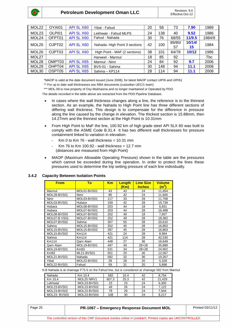
3.4.2 Capacity Between Isolation Points
From To Km Length (Km)
Line Size Inches
Volume (m
3)
Marmul MOL01-BVS01 43 43 24 11,654
MOL28-BVS01 Nimr 85 42 24 11,600
Nimr MOL03-BVS01 117 33 28 11,768
MOL03-BVS01 Hubara 159 42 28 15,739
Hubara MOL08-BVS03 203 44 18 6,831
Hubara MOL07-BVS01 203 44 28 16,488
MOL08-BVS03 MOL07-BVS02 252 49 18 7,607
MOL07-B VS01 MOL07-BVS02 252 49 28 18,362
MOL07-BVS02 Sahma 307 55 28 20,610
Sahma MOL15-BVS02 352 45 28 16,863
MOL15-BVS01 MOL15-BVS02 397 45 28 16,863
MOL15-BVS02 Km114 421 24 28 8,994
Sahma Km114 421 114 28 42,530
Km114 Qarn Alam 448 27 36 16,649
Qarn Alam MOL19-BVS01 497 49 28+28 35,889
MOL19-BVS01 Km83 531 34 28+28 24,902
Km83 ML21-BVS01 551 20 36 12,067
MOL21-BVS01 Nahada 582 32 36 19,307
Yibal MOL22-BVS01 28 28 20 5,328
MOL22-BVS01 Fahud 59 31 20 5,898
N.B Nahada is at chainage F75.6 on the Fahud line, but is considered at chainage 582 from Marmul
Nahada Km 10.4 582 10.4 42 8,754
Km 10.4 MOL25 NRV1 607.3 25.3 42 21,429
Lekhwair MOL23-BVS01 23 23 24 6,300
MOL23-BVS01 MOL23-BVS02 49 26 24 7,122
MOL23-BVS02 MOL23 BVS03 78 29 24 7,944
MOL23- BVS03 MOL23-BVS04 108 30 24 8,217
Petroleum Development Oman LLC
Revision: 9.0 Effective:Oct-12
Page 26 PR-1067 – Emergency Response Document MOL Printed 03/11/12
The controlled version of this CMF Document resides online in Livelink®. Printed copies are UNCONTROLLED.
MOL23-BVS04 Fahud 138 30 24 8,217
Fahud MOL24-BVS01 2 2 30 860
MOL24-BVS01 MOL24-NRVF1 21 19 30 8,169
MOL24-NRVF1 MOL24-BVS02 40 19 30 8,169
MOL24-BVS02 Nahada 75.6 35.6 30 15,442
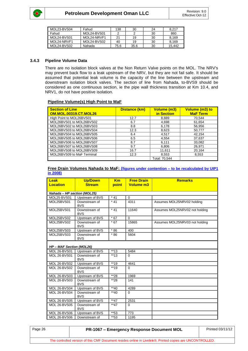
3.4.3 Pipeline Volume Data
There are no isolation block valves at the Non Return Valve points on the MOL. The NRV's may prevent back flow to a leak upstream of the NRV, but they are not fail safe. It should be assumed that potential leak volume is the capacity of the line between the upstream and downstream isolation block valves. The section of line from Nahada, to-BVS9 should be considered as one continuous section, ie the pipe wall thickness transition at Km 10.4, and NRV1, do not have positive isolation.
Pipeline Volume(s) High Point to MaF
Section of Line OM.MOL.00319.CT.MOL26
Distance (km) Volume (m3) in Section
Volume (m3) to MaF Term
High Point to MOL26BVS01 12.7 8,889 70,544
MOL26BVS01 to MOL26BVS02 6.7 4,698 61,654
MOL26BVS02 to MOL26BVS03 8.8 6,178 56,956
MOL26BVS03 to MOL26BVS04 12.3 8,623 50,777
MOL26BVS04 to MOL26BVS05 6.4 4,517 42,154
MOL26BVS05 to MOL26BVS06 6.5 4,554 37,637
MOL26BVS06 to MOL26BVS07 8.7 6,111 33,082
MOL26BVS07 to MOL26BVS08 9.7 6,806 26,971
MOL26BVS08 to MOL26BVS09 16.7 11,611 20,164
MOL26BVS09 to MaF Terminal 12.3 8,553 8,553
Total: 70,544
Free Drain Volumes Nahada to MaF: (figures under contention – to be recalculated by UIP1
in 2008)
Leak Location
Up/Down Stream
Km point
Free Drain Volume m3
Remarks
Nahada – HP section (MOL25)
MOL25-BVS01 Upstream of BVS * 41 0
MOL25BVS01 Downstream of BVS
* 41 4311 Assumes MOL25NRV02 holding
MOL25BVS01 Downstream of BVS
* 41 11640 Assumes MOL25NRV02 not holding
MOL25BVS02 Upstream of BVS * 67 0
MOL25BVS02 Downstream of BVS
* 67 15865 Assumes MOL25NRV03 not holding
MOL25BVS03 Upstream of BVS * 86 400
MOL25BVS03 Downstream of BVS
* 86 5604
HP – MAF Section (MOL26)
MOL 26-BVS01 Upstream of BVS **13 5484
MOL 26-BVS01 Downstream of BVS
**13 0
MOL 26-BVS02 Upstream of BVS **19 4641
MOL 26-BVS02 Downstream of BVS
**19 0
MOL 26-BVS03 Upstream of BVS **28 1969
MOL 26-BVS03 Downstream of BVS
**28 141
MOL 26-BVS04 Upstream of BVS **40 4289
MOL 26-BVS04 Downstream of BVS
**40 0
MOL 26-BVS05 Upstream of BVS **47 2531
MOL 26-BVS05 Downstream of BVS
**47 0
MOL 26-BVS06 Upstream of BVS **53 773
MOL 26-BVS06 Downstream of **53 1195
Petroleum Development Oman LLC
Revision: 9.0 Effective:Oct-12
Page 27 PR-1067 – Emergency Response Document MOL Printed 03/11/12
The controlled version of this CMF Document resides online in Livelink®. Printed copies are UNCONTROLLED.
Leak Location
Up/Down Stream
Km point
Free Drain Volume m3
Remarks
BVS
MOL 26-BVS07 Upstream of BVS **62 4043
MOL 26-BVS07 Downstream of BVS
**62 1125
MOL 26-BVS08 Upstream of BVS **72 229
MOL 26-BVS08 Downstream of BVS
**72 70
MOL 26-BVS09 Upstream of BVS **89 3234
MOL 26-BVS09 Downstream of BVS
**89 563
* Distance in KM from Nahada.
** Distance in KM from High point.
Volume Calculations
Example volume calculation for MOL 26-BVS09 to MaF Terminal:
Wall Thickness = 12.7 mm = 0.0127 m.
ID = 38"= 38 * 25.4 = 956.2 mm = 0.9652 m.
0.9652 2(0.0127) = 0.9398
V = (0.9398)² * 12,330 = 8,532 m3
4
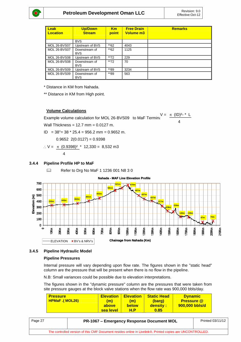
3.4.4 Pipeline Profile HP to MaF
Refer to Drg No MaF 1 1236 001 N8 3 0
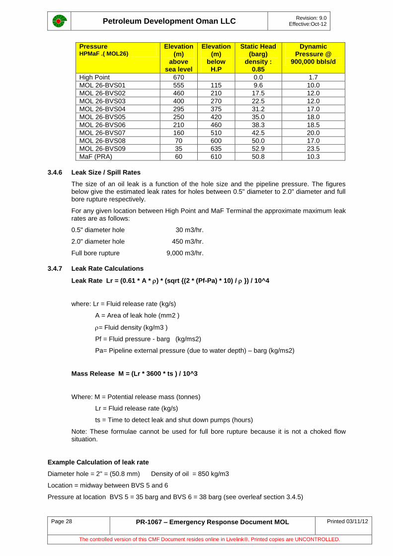
3.4.5 Pipeline Hydraulic Model
Pipeline Pressures
Internal pressure will vary depending upon flow rate. The figures shown in the "static head" column are the pressure that will be present when there is no flow in the pipeline.
N.B: Small variances could be possible due to elevation interpretations.
The figures shown in the "dynamic pressure" column are the pressures that were taken from site pressure gauges at the block valve stations when the flow rate was 900,000 bbls/day.
Pressure HPMaF .( MOL26)
Elevation (m)
above sea level
Elevation (m)
below H.P
Static Head (barg)
density : 0.85
Dynamic Pressure @
900,000 bbls/d
V = (ID)²- * L
4
Nahada - MAF Line Elevation Profile
Chainage from Nahada (Km)
Ele
va
tio
n (
m)
ELEVATION BV’s & NRV’s
330m343m
362m401m
453m
0
100
200
300
400
500
600
700
0
10K
m
20K
m
30K
m
40K
m
50K
m
60K
m
70K
m
80K
m
90K
m
100K
m
110K
m
120K
m
130K
m
140K
m
150K
m
160K
m
170K
m
180K
m
190K
m
200K
m
210K
m
581m
621m 670m
497m
437m
437m
317m
238m224m
140m 139m
47m 70m
Nahada - MAF Line Elevation Profile
Chainage from Nahada (Km)
Ele
va
tio
n (
m)
ELEVATION BV’s & NRV’sELEVATION BV’s & NRV’s
330m343m
362m401m
453m
0
100
200
300
400
500
600
700
0
10K
m
20K
m
30K
m
40K
m
50K
m
60K
m
70K
m
80K
m
90K
m
100K
m
110K
m
120K
m
130K
m
140K
m
150K
m
160K
m
170K
m
180K
m
190K
m
200K
m
210K
m
581m
621m 670m
497m
437m
437m
317m
238m224m
140m 139m
47m 70m
330m343m
362m401m
453m
0
100
200
300
400
500
600
700
0
10K
m
20K
m
30K
m
40K
m
50K
m
60K
m
70K
m
80K
m
90K
m
100K
m
110K
m
120K
m
130K
m
140K
m
150K
m
160K
m
170K
m
180K
m
190K
m
200K
m
210K
m
581m
621m 670m
497m
437m
437m
317m
238m224m
140m 139m
47m 70m
Petroleum Development Oman LLC
Revision: 9.0 Effective:Oct-12
Page 28 PR-1067 – Emergency Response Document MOL Printed 03/11/12
The controlled version of this CMF Document resides online in Livelink®. Printed copies are UNCONTROLLED.
Pressure HPMaF .( MOL26)
Elevation (m)
above sea level
Elevation (m)
below H.P
Static Head (barg)
density : 0.85
Dynamic Pressure @
900,000 bbls/d
High Point 670 0.0 1.7
MOL 26-BVS01 555 115 9.6 10.0
MOL 26-BVS02 460 210 17.5 12.0
MOL 26-BVS03 400 270 22.5 12.0
MOL 26-BVS04 295 375 31.2 17.0
MOL 26-BVS05 250 420 35.0 18.0
MOL 26-BVS06 210 460 38.3 18.5
MOL 26-BVS07 160 510 42.5 20.0
MOL 26-BVS08 70 600 50.0 17.0
MOL 26-BVS09 35 635 52.9 23.5
MaF (PRA) 60 610 50.8 10.3
3.4.6 Leak Size / Spill Rates
The size of an oil leak is a function of the hole size and the pipeline pressure. The figures below give the estimated leak rates for holes between 0.5" diameter to 2.0" diameter and full bore rupture respectively.
For any given location between High Point and MaF Terminal the approximate maximum leak rates are as follows:
0.5" diameter hole 30 m3/hr.
2.0" diameter hole 450 m3/hr.
Full bore rupture 9,000 m3/hr.
3.4.7 Leak Rate Calculations
Leak Rate Lr = (0.61 * A * ) * (sqrt {(2 * (Pf-Pa) * 10) / }) / 10^4
where: Lr = Fluid release rate (kg/s)
A = Area of leak hole (mm2 )
= Fluid density (kg/m3 )
Pf = Fluid pressure - barg (kg/ms2)
Pa= Pipeline external pressure (due to water depth) – barg (kg/ms2)
Mass Release M = (Lr * 3600 * ts ) / 10^3
Where: M = Potential release mass (tonnes)
Lr = Fluid release rate (kg/s)
ts = Time to detect leak and shut down pumps (hours)
Note: These formulae cannot be used for full bore rupture because it is not a choked flow situation.
Example Calculation of leak rate
Diameter hole = 2" = (50.8 mm) Density of oil = 850 kg/m3
Location = midway between BVS 5 and 6
Pressure at location BVS 5 = 35 barg and BVS 6 = 38 barg (see overleaf section 3.4.5)
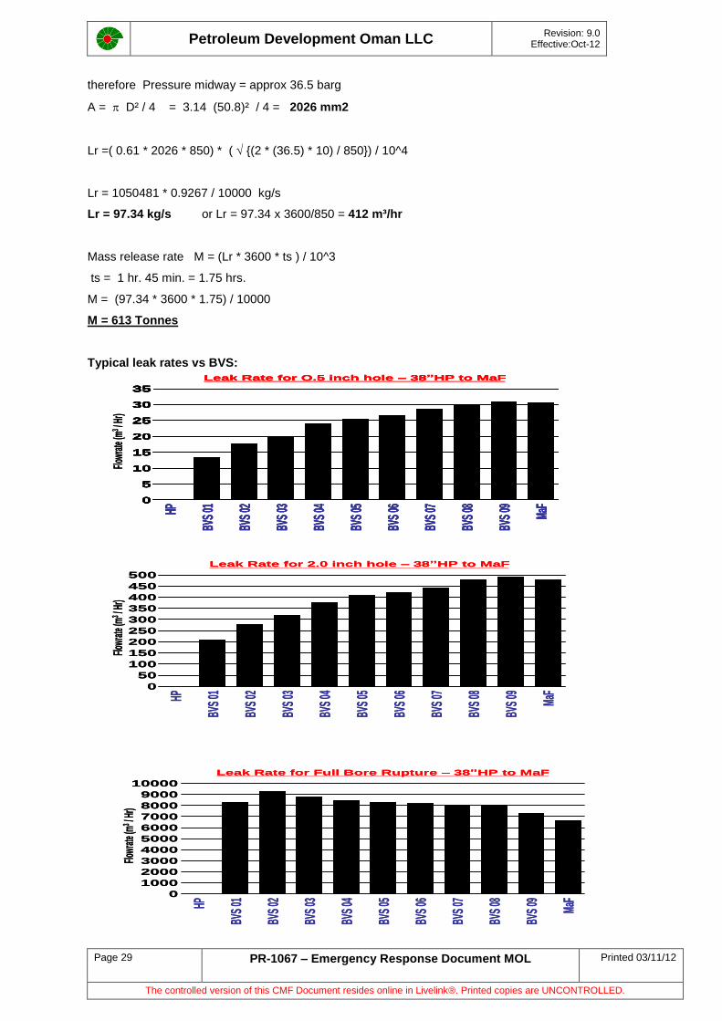
Petroleum Development Oman LLC
Revision: 9.0 Effective:Oct-12
Page 29 PR-1067 – Emergency Response Document MOL Printed 03/11/12
The controlled version of this CMF Document resides online in Livelink®. Printed copies are UNCONTROLLED.
therefore Pressure midway = approx 36.5 barg
A = D² / 4 = 3.14 (50.8)² / 4 = 2026 mm2
Lr =( 0.61 * 2026 * 850) * ( {(2 * (36.5) * 10) / 850}) / 10^4
Lr = 1050481 * 0.9267 / 10000 kg/s
Lr = 97.34 kg/s or Lr = 97.34 x 3600/850 = 412 m³/hr
Mass release rate M = (Lr * 3600 * ts ) / 10^3
ts = 1 hr. 45 min. = 1.75 hrs.
M = (97.34 * 3600 * 1.75) / 10000
M = 613 Tonnes
Typical leak rates vs BVS:
Leak Rate for Full Bore Rupture – 38”HP to MaF
10000
9000
8000
7000
6000
5000
4000
3000
2000
1000
0
HP
BVS
01
BVS
02
BVS
03
BVS
04
BVS
05
BVS
06
BVS
07
BVS
08
BVS
09 MaF
Flow
rate
(m3
/ Hr)
Leak Rate for Full Bore Rupture – 38”HP to MaF
10000
9000
8000
7000
6000
5000
4000
3000
2000
1000
0
HP
BVS
01
BVS
02
BVS
03
BVS
04
BVS
05
BVS
06
BVS
07
BVS
08
BVS
09 MaF
Flow
rate
(m3
/ Hr)
500
450
400
350
300
250
200
150
100
50
0
HP
BVS
01
BVS
02
BVS
03
BVS
04
BVS
05
BVS
06
BVS
07
BVS
08
BVS
09 MaF
Leak Rate for 2.0 inch hole – 38”HP to MaF
Flow
rate
(m3
/ Hr)
500
450
400
350
300
250
200
150
100
50
0
HP
BVS
01
BVS
02
BVS
03
BVS
04
BVS
05
BVS
06
BVS
07
BVS
08
BVS
09 MaF
Leak Rate for 2.0 inch hole – 38”HP to MaF
Flow
rate
(m3
/ Hr)
35
30
25
20
15
10
5
0
HP
BVS
01
BVS
02
BVS
03
BVS
04
BVS
05
BVS
06
BVS
07
BVS
08
BVS
09 MaF
Leak Rate for O.5 inch hole – 38”HP to MaF
Flow
rate
(m3
/ Hr)
35
30
25
20
15
10
5
0
HP
BVS
01
BVS
02
BVS
03
BVS
04
BVS
05
BVS
06
BVS
07
BVS
08
BVS
09 MaF
Leak Rate for O.5 inch hole – 38”HP to MaF
35
30
25
20
15
10
5
0
HP
BVS
01
BVS
02
BVS
03
BVS
04
BVS
05
BVS
06
BVS
07
BVS
08
BVS
09 MaF
35
30
25
20
15
10
5
0
35
30
25
20
15
10
5
0
HP
BVS
01
BVS
02
BVS
03
BVS
04
BVS
05
BVS
06
BVS
07
BVS
08
BVS
09 MaF
Leak Rate for O.5 inch hole – 38”HP to MaF
Flow
rate
(m3
/ Hr)
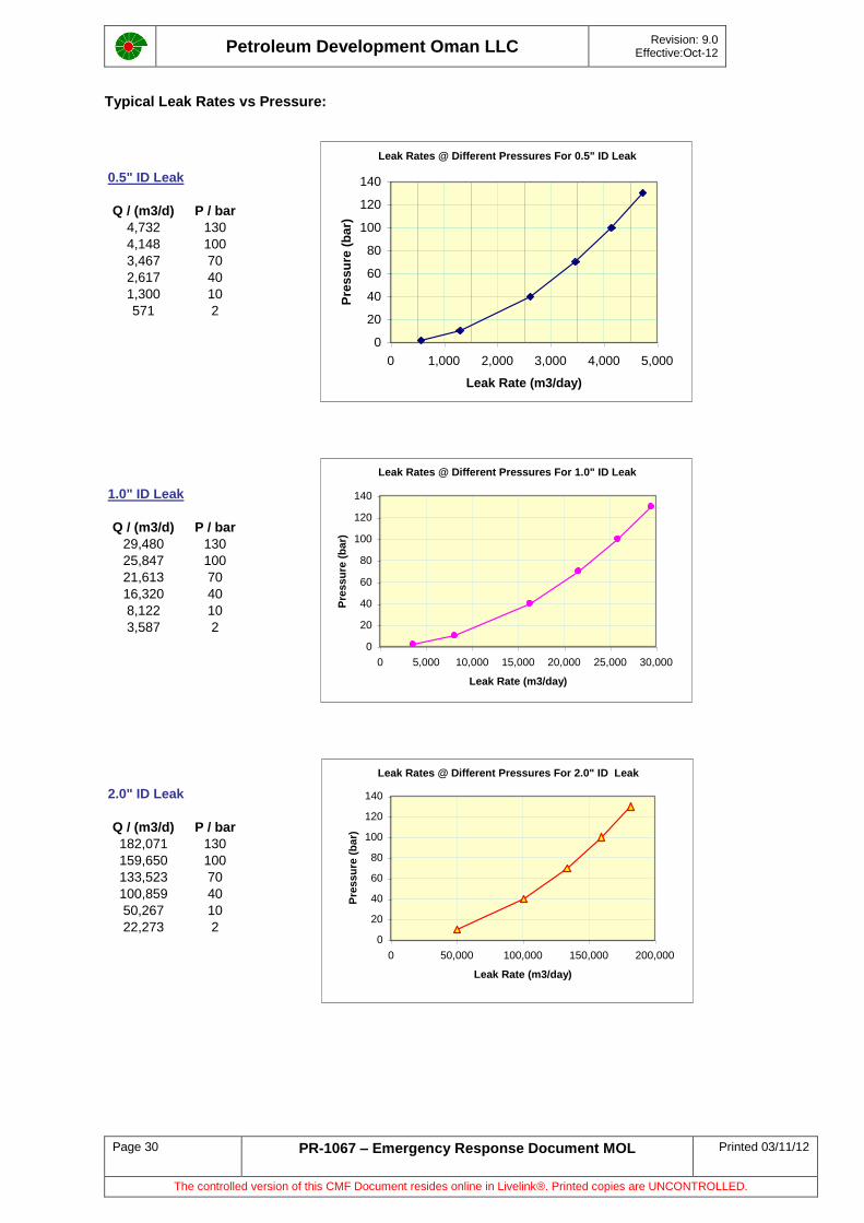
Petroleum Development Oman LLC
Revision: 9.0 Effective:Oct-12
Page 30 PR-1067 – Emergency Response Document MOL Printed 03/11/12
The controlled version of this CMF Document resides online in Livelink®. Printed copies are UNCONTROLLED.
Typical Leak Rates vs Pressure:
0.5" ID Leak
Q / (m3/d) P / bar
4,732 130
4,148 100
3,467 70
2,617 40
1,300 10
571 2
1.0" ID Leak
Q / (m3/d) P / bar
29,480 130
25,847 100
21,613 70
16,320 40
8,122 10
3,587 2
2.0" ID Leak
Q / (m3/d) P / bar
182,071 130
159,650 100
133,523 70
100,859 40
50,267 10
22,273 2
Leak Rates @ Different Pressures For 0.5" ID Leak
0
20
40
60
80
100
120
140
0 1,000 2,000 3,000 4,000 5,000
Leak Rate (m3/day)
Pre
ss
ure
(b
ar)
Leak Rates @ Different Pressures For 1.0" ID Leak
0
20
40
60
80
100
120
140
0 5,000 10,000 15,000 20,000 25,000 30,000
Leak Rate (m3/day)
Pre
ssu
re (
ba
r)
Leak Rates @ Different Pressures For 2.0" ID Leak
0
20
40
60
80
100
120
140
0 50,000 100,000 150,000 200,000
Leak Rate (m3/day)
Pre
ssu
re (
ba
r)
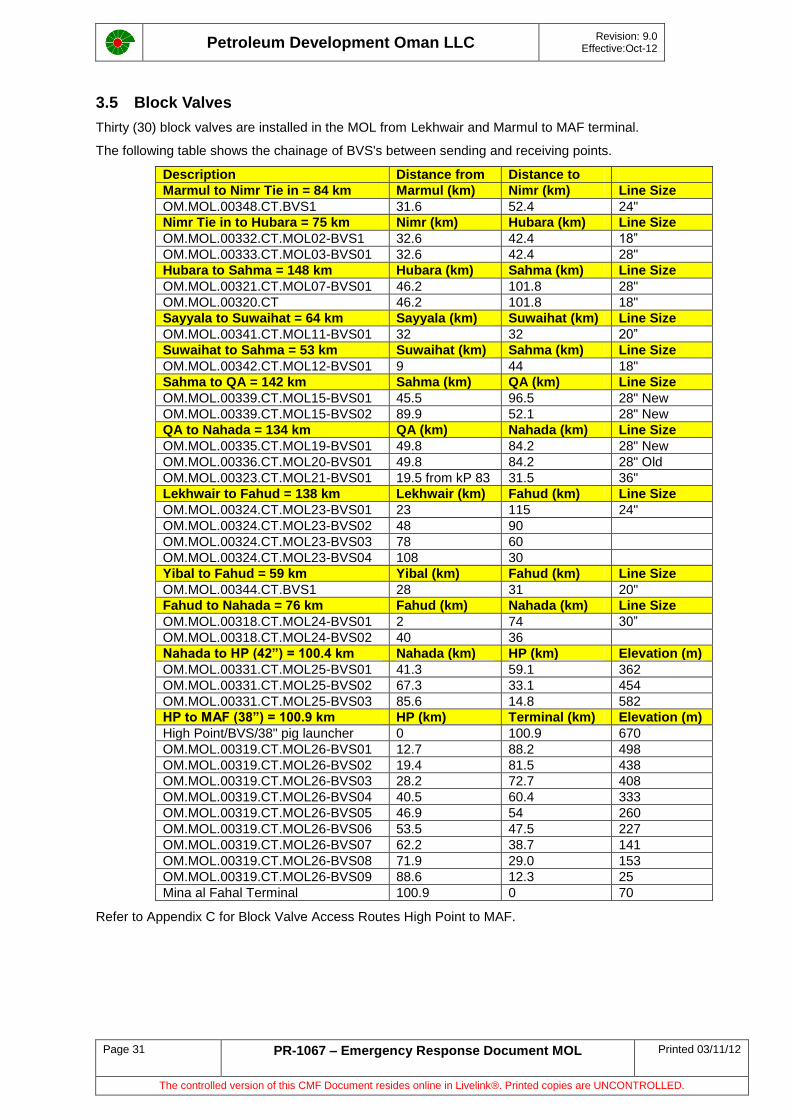
Petroleum Development Oman LLC
Revision: 9.0 Effective:Oct-12
Page 31 PR-1067 – Emergency Response Document MOL Printed 03/11/12
The controlled version of this CMF Document resides online in Livelink®. Printed copies are UNCONTROLLED.
3.5 Block Valves
Thirty (30) block valves are installed in the MOL from Lekhwair and Marmul to MAF terminal.
The following table shows the chainage of BVS's between sending and receiving points.
Description Distance from Distance to
Marmul to Nimr Tie in = 84 km Marmul (km) Nimr (km) Line Size
OM.MOL.00348.CT.BVS1 31.6 52.4 24"
Nimr Tie in to Hubara = 75 km Nimr (km) Hubara (km) Line Size
OM.MOL.00332.CT.MOL02-BVS1 32.6 42.4 18”
OM.MOL.00333.CT.MOL03-BVS01 32.6 42.4 28"
Hubara to Sahma = 148 km Hubara (km) Sahma (km) Line Size
OM.MOL.00321.CT.MOL07-BVS01 46.2 101.8 28"
OM.MOL.00320.CT 46.2 101.8 18"
Sayyala to Suwaihat = 64 km Sayyala (km) Suwaihat (km) Line Size
OM.MOL.00341.CT.MOL11-BVS01 32 32 20”
Suwaihat to Sahma = 53 km Suwaihat (km) Sahma (km) Line Size
OM.MOL.00342.CT.MOL12-BVS01 9 44 18"
Sahma to QA = 142 km Sahma (km) QA (km) Line Size
OM.MOL.00339.CT.MOL15-BVS01 45.5 96.5 28" New
OM.MOL.00339.CT.MOL15-BVS02 89.9 52.1 28" New
QA to Nahada = 134 km QA (km) Nahada (km) Line Size
OM.MOL.00335.CT.MOL19-BVS01 49.8 84.2 28" New
OM.MOL.00336.CT.MOL20-BVS01 49.8 84.2 28" Old
OM.MOL.00323.CT.MOL21-BVS01 19.5 from kP 83 31.5 36"
Lekhwair to Fahud = 138 km Lekhwair (km) Fahud (km) Line Size
OM.MOL.00324.CT.MOL23-BVS01 23 115 24"
OM.MOL.00324.CT.MOL23-BVS02 48 90
OM.MOL.00324.CT.MOL23-BVS03 78 60
OM.MOL.00324.CT.MOL23-BVS04 108 30
Yibal to Fahud = 59 km Yibal (km) Fahud (km) Line Size
OM.MOL.00344.CT.BVS1 28 31 20"
Fahud to Nahada = 76 km Fahud (km) Nahada (km) Line Size
OM.MOL.00318.CT.MOL24-BVS01 2 74 30”
OM.MOL.00318.CT.MOL24-BVS02 40 36
Nahada to HP (42”) = 100.4 km Nahada (km) HP (km) Elevation (m)
OM.MOL.00331.CT.MOL25-BVS01 41.3 59.1 362
OM.MOL.00331.CT.MOL25-BVS02 67.3 33.1 454
OM.MOL.00331.CT.MOL25-BVS03 85.6 14.8 582
HP to MAF (38”) = 100.9 km HP (km) Terminal (km) Elevation (m)
High Point/BVS/38" pig launcher 0 100.9 670
OM.MOL.00319.CT.MOL26-BVS01 12.7 88.2 498
OM.MOL.00319.CT.MOL26-BVS02 19.4 81.5 438
OM.MOL.00319.CT.MOL26-BVS03 28.2 72.7 408
OM.MOL.00319.CT.MOL26-BVS04 40.5 60.4 333
OM.MOL.00319.CT.MOL26-BVS05 46.9 54 260
OM.MOL.00319.CT.MOL26-BVS06 53.5 47.5 227
OM.MOL.00319.CT.MOL26-BVS07 62.2 38.7 141
OM.MOL.00319.CT.MOL26-BVS08 71.9 29.0 153
OM.MOL.00319.CT.MOL26-BVS09 88.6 12.3 25
Mina al Fahal Terminal 100.9 0 70
Refer to Appendix C for Block Valve Access Routes High Point to MAF.
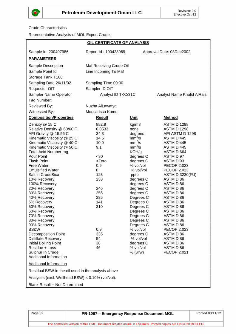
Petroleum Development Oman LLC
Revision: 9.0 Effective:Oct-12
Page 32 PR-1067 – Emergency Response Document MOL Printed 03/11/12
The controlled version of this CMF Document resides online in Livelink®. Printed copies are UNCONTROLLED.
Crude Characteristics
Representative Analysis of MOL Export Crude:
OIL CERTIFICATE OF ANALYSIS
Sample Id: 200407986 Report Id : 100428969 Approval Date: 03Dec2002
PARAMETERS
Sample Description Maf Receiving Crude Oil
Sample Point Id Line Incoming To Maf
Storage Tank T106
Sampling Date 26/11/02 Sampling Time 09:00
Requester OIT Sampler ID OIT
Sampler Name Operator Analyst ID TKC/31C Analyst Name Khalid AlRaisi
Tag Number:
Reviewed By: Nuzha AlLawatya
Witnessed By: Moosa Issa Kamo
Composition/Properties Result Unit Method
Density @ 15 C 852.9 kg/m3 ASTM D 1298 Relative Density @ 60/60 F 0.8533 none ASTM D 1298 API Gravity @ 15.56 C 34.3 degrees API ASTM D 1298 Kinematic Viscosity @ 25 C 14.5 mm
2/s ASTM D 445
Kinematic Viscosity @ 40 C 10.9 mm2/s ASTM D 445
Kinematic Viscosity @ 50 C 9.1 mm2/s ASTM D 445
Total Acid Number mg KOH/g ASTM D 664 Pour Point <30 degrees C ASTM D 97 Flash Point <Zero degrees C ASTM D 93 Free Water 0.9 % vol/vol PECOP 2.023 Emulsified Water 0 % vol/vol PECOP 2.023 Salt in CrudeSica 125 pptb ASTM D 3230(FU) 10% Recovery 238 degrees C ASTM D 86 100% Recovery degrees C ASTM D 86 20% Recovery 246 degrees C ASTM D 86 30% Recovery 255 degrees C ASTM D 86 40% Recovery 285 Degrees C ASTM D 86 5% Recovery 141 Degrees C ASTM D 86 50% Recovery 310 Degrees C ASTM D 86 60% Recovery Degrees C ASTM D 86 70% Recovery Degrees C ASTM D 86 80% Recovery Degrees C ASTM D 86 90% Recovery Degrees C ASTM D 86 BS&W 0.9 % vol/vol PECOP 2.023 Decomposition Point 335 degrees C ASTM D 86 Distillate Recovery 54 % vol/vol ASTM D 86 Initial Boiling Point 38 degrees C ASTM D 86 Residue + Loss 46 % vol/vol ASTM D 86 Sulphur In Crude % (w/w) PECOP 2.021 Additional Information
Additional Information
Residual BSW in the oil used in the analysis above
Analyses (excl. Wellhead BSW) < 0.10% (vol/vol).
Blank Result = Not Determined
Petroleum Development Oman LLC
Revision: 9.0 Effective:Oct-12
Page 33 PR-1067 – Emergency Response Document MOL Printed 03/11/12
The controlled version of this CMF Document resides online in Livelink®. Printed copies are UNCONTROLLED.
4 Emergency Repairs
4.1 System Preparation
All activities relating to system preparation will be performed by UIP/4 personnel. Subsequent work, e.g. earth moving, will be performed only when authorised by the UIP/4 site representative (CSR).
Before any work can be carried out on a pipeline, the pipeline is required to be made safe.
4.1.1 Line Isolation and Depressurisation
To isolate the pipeline effectively, the adjacent upstream and downstream block and bypass valves to the leak area will be closed and sealed. To enhance safety during the emergency repair phase, the next nearest upstream and downstream block and bypass valves will also be closed and sealed affording a double block both upstream and downstream of the leak area. If positive isolation cannot be achieved, the UIP/4 site representative will be informed. The UIP/4 site representative will determine additional requirements to obtain full isolation.
Depressurisation of isolation zones will commence on the instruction from UIP/6 and UIP/4 via the onsite, UIP/4 site representative. Any venting will be carried out at suitable block valve station bypass locations where no danger exists to personnel within the venting area from the vented gas.
Before any repair work (e.g. to allow the installation of a PLIDCO clamp) can proceed, the isolated pipeline section must be confirmed gas free unless agreed otherwise by UIP/6 and UIP/4. There must be no explosive mixtures of gas and air. The gas inventory in the isolated section will be removed using air powered blowers located at the block valve station vents. Ideally, air blowers should be located at both block valve stations and the air allowed to escape through the rupture. If only one air powered blower is used, the other block valve station vent should be open to increase the amount of air drawn into the pipeline.
An alternative approach will be to purge the isolated line section with nitrogen. If the line is leaking, nitrogen shall be injected at the upstream and downstream block valve station and merged from these two locations towards the ruptured section.
The leak location and block valve station vents will then be tested for gas. Only when all three locations indicate no gas can the line be declared gas free. Continuous gas testing must be performed throughout the period of the repair. In case of a small leak, the nitrogen can be supplied via the bypass line (vent stack connection) of the valve station and vented at the other isolation valve.
4.1.2 Repair Methods
All emergency repairs to a pipeline will be performed in accordance with the Emergency Repair Manual by UIP/4 or UIP/2 personnel with guidance provided by UIPT (CFDH Pipelines). Immediate repairs required will be organised and carried out by the area team with assistance from UIP/4 site representative. Planned long term repairs will be carried out by UIP/2 section.
Emergency repairs can be either temporary or permanent. Temporary repairs have to be made permanent within 3 months (see Pipeline and Flow Line Integrity Management, ERD1001, Section 8.5.3. b).
Prior to any cutting of a pipeline, the Cathodic Protection system has to be isolated or a bonding cable attached to the pipe on either side of the damaged section.
4.1.3 Temporary Repairs
If the rupture is small, a clamp (e.g. Plidco Split + Sleeve), may be fitted to contain the leak until the system can be prepared for a permanent repair. The clamp comprises two halves which are bolted together and contain a packing which forms a seal around the pipe. The standard Plidco Split + Sleeve can be used on corrosion pit leaks and ruptures up to 200 mm (7.9”) long and pressures up to 68.96 kPa. Special Plidco Split + Sleeves are also available for use on longer ruptures and at higher pressures. Manufacturers documentation states that the clamps can be welded and become a permanent fixture, however within PDO these clamps are only considered temporary.
A Plidco Smith + Clamp is also available to seal pinhole leaks. This type of clamp consists of a steel force screw which is located in the leak and held in position by a steel clamp. The Plidco Weld + Cap is similar to the Smith + Clamp but has a weld cap instead of the force screw.
Petroleum Development Oman LLC
Revision: 9.0 Effective:Oct-12
Page 34 PR-1067 – Emergency Response Document MOL Printed 03/11/12
The controlled version of this CMF Document resides online in Livelink®. Printed copies are UNCONTROLLED.
4.1.4 Permanent Repairs
Permanent repairs involve removing damaged sections of pipeline and replacing them with new sections of the same grade and wall thickness. The line is cut using a cold cutting machine so that cylindrical stopper air bags can be installed inside the pipe to ensure that no gas is present in the repair area. Before the pipeline is cut, it must be restrained to ensure that there is no movement due to possible stresses in the pipeline.
The replacement section will be welded in place using PDO approved welding procedures and the welds shall be subject to 100% radiography. The air bags should be removed thorough nozzles previously welded onto the pipeline.
A “Clamped Spool Piece Repair with End Couplings” can also be considered as a permanent repair method, if approved by the Asset Holder.
A repair with Weld End Couplings and Pipe Spool is recommend on a rupture where the length of the pipe damage is beyond the limit established by the split sleeve manufacturer. The seal is created when elastomer packing is compressed against the carrier pipe by the tightening of the thrust screws. Operations can be resumed as soon as the bolting of the weld and coupling is completed. Once the surrounding area has been cleaned, welding can be safely undertaken.
Detailed execution of the repair methods is detailed in:
Pipeline Emergency Repair Manual GU379
4.1.5 Hot Tapping and Stoppling
Hot tapping (see Hot Tapping, ERD 3807) is used to install new branch connections onto an existing pipeline without interrupting the normal operating conditions.
The hot tap machine consists of the tapping machine, which can be either pneumatically or hydraulically driven, a cutter and a pilot. The coupon which is cut out of the pipe wall should be forced out of the pipe by the pressure of the process fluid and retained in the cutter; this can also be achieved by fitting a coupon catcher to the cutter assembly.
The hot tap is achieved by welding a weldolet or split tee on to the pipeline, then installing a valve onto the new branch. The sequence of activities is as follows:
1. Pressure test new branch fitting and valve(s)
2. Install the hot tap machine on the branch assembly
3. Pressure test the assembly
4. Open the valve
5. Lower the hot tap cutter through the valve until the pilot penetrates the pipe wall
6. Allow the assembly to fill up with process fluid by opening the hot tap machine vent; once full,
close the vent
7. Continue to lower the cutter until it has completely penetrated the pipeline
8. Withdraw the cutter up into the hot tap machine and close the valve
9. Remove the hot tap machine
When a valve is not required on the branch, a LocORing flange and plug can be installed and a wafer valve used. The LocORing plug is installed after the hot tap is completed by using the hot tapping machine to lower the plug through the valve, then positioning the plug in the LocORing flange and tightening the retaining screws on the flange. This seals the branch and allows the hot tapping machine and wafer valve to be removed. The plug can be removed by reversing the installation procedure.
Stoppling is performed in conjunction with hot tapping. Once the hot tap has been completed, the hot tapping machine is replaced by the stoppling machine, which consists of a hydraulic cylinder and a housing containing a fold away plug assembly. When the plug assembly is lowered into the pipe, the assembly unfolds and forms a plug inside the pipe. By using two stoppling machines, a section of pipeline can be isolated and removed or worked on.
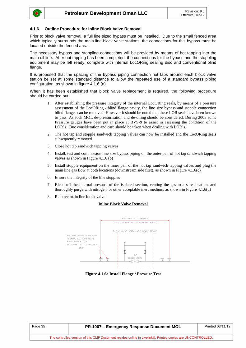
Petroleum Development Oman LLC
Revision: 9.0 Effective:Oct-12
Page 35 PR-1067 – Emergency Response Document MOL Printed 03/11/12
The controlled version of this CMF Document resides online in Livelink®. Printed copies are UNCONTROLLED.
4.1.6 Outline Procedure for Inline Block Valve Removal
Prior to block valve removal, a full line sized bypass must be installed. Due to the small fenced area which typically surrounds the main line block valve stations, the connections for this bypass must be located outside the fenced area.
The necessary bypass and stoppling connections will be provided by means of hot tapping into the main oil line. After hot tapping has been completed, the connections for the bypass and the stoppling equipment may be left ready, complete with internal LocORing sealing disc and conventional blind flange.
It is proposed that the spacing of the bypass piping connection hot taps around each block valve station be set at some standard distance to allow the repeated use of a standard bypass piping configuration, as shown in figure 4.1.6 (a).
When it has been established that block valve replacement is required, the following procedure should be carried out:
1. After establishing the pressure integrity of the internal LocORing seals, by means of a pressure
assessment of the LocORing / blind flange cavity, the line size bypass and stopple connection
blind flanges can be removed. However it should be noted that these LOR seals have been known
to pass. As such MOL de-pressurisation and de-oiling should be considered. During 2005 some
Pressure gauges have been put in place at BVS-9 to assist in assessing the condition of the
LOR’s. Due consideration and care should be taken when dealing with LOR’s.
2. The hot tap and stopple sandwich tapping valves can now be installed and the LocORing seals
subsequently removed.
3. Close hot tap sandwich tapping valves
4. Install, test and commission line size bypass piping on the outer pair of hot tap sandwich tapping
valves as shown in Figure 4.1.6 (b)
5. Install stopple equipment on the inner pair of the hot tap sandwich tapping valves and plug the
main line gas flow at both locations (downstream side first), as shown in Figure 4.1.6(c)
6. Ensure the integrity of the line stopples
7. Bleed off the internal pressure of the isolated section, venting the gas to a safe location, and
thoroughly purge with nitrogen, or other acceptable inert medium, as shown in Figure 4.1.6(d)
8. Remove main line block valve
Inline Block Valve Removal
Figure 4.1.6a Install Flange / Pressure Test
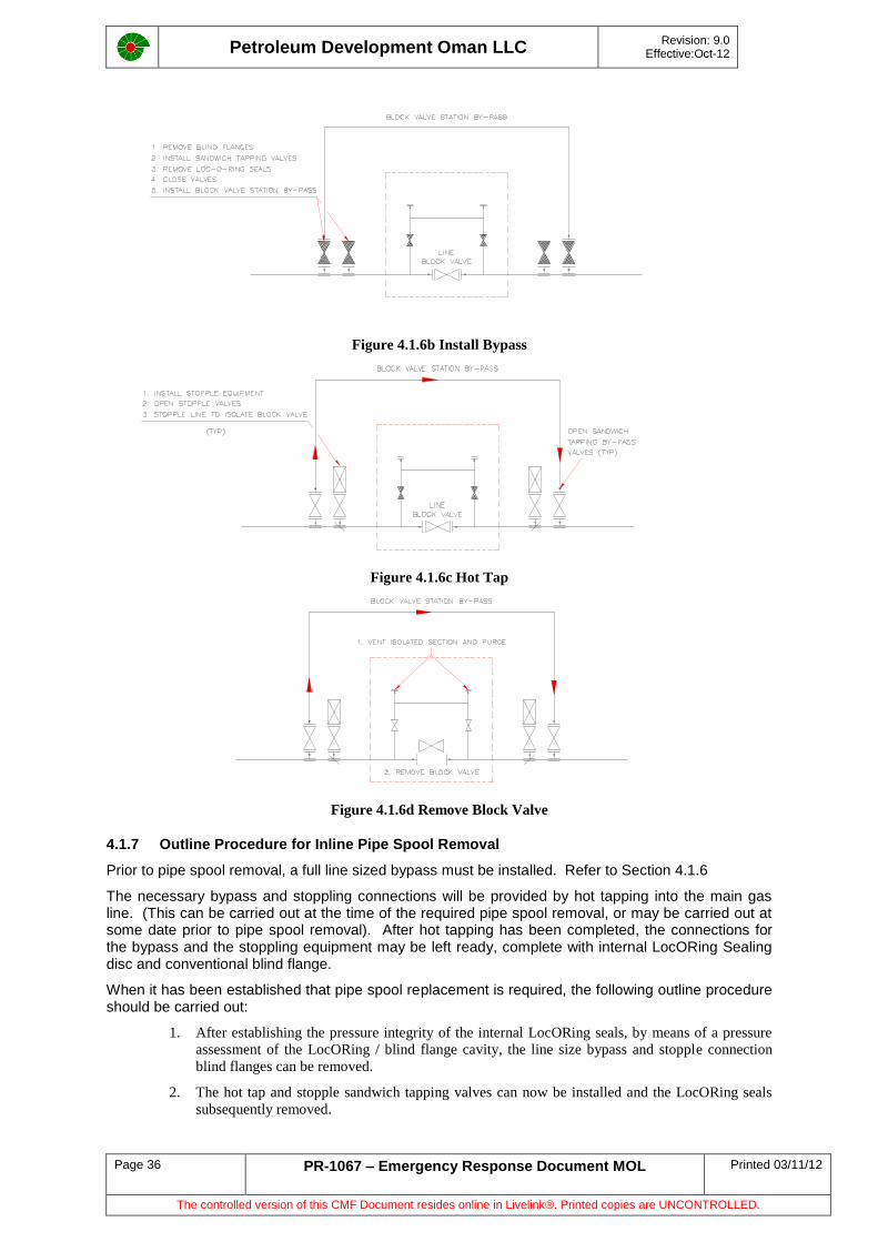
Petroleum Development Oman LLC
Revision: 9.0 Effective:Oct-12
Page 36 PR-1067 – Emergency Response Document MOL Printed 03/11/12
The controlled version of this CMF Document resides online in Livelink®. Printed copies are UNCONTROLLED.
Figure 4.1.6b Install Bypass
Figure 4.1.6c Hot Tap
Figure 4.1.6d Remove Block Valve
4.1.7 Outline Procedure for Inline Pipe Spool Removal
Prior to pipe spool removal, a full line sized bypass must be installed. Refer to Section 4.1.6
The necessary bypass and stoppling connections will be provided by hot tapping into the main gas line. (This can be carried out at the time of the required pipe spool removal, or may be carried out at some date prior to pipe spool removal). After hot tapping has been completed, the connections for the bypass and the stoppling equipment may be left ready, complete with internal LocORing Sealing disc and conventional blind flange.
When it has been established that pipe spool replacement is required, the following outline procedure should be carried out:
1. After establishing the pressure integrity of the internal LocORing seals, by means of a pressure
assessment of the LocORing / blind flange cavity, the line size bypass and stopple connection
blind flanges can be removed.
2. The hot tap and stopple sandwich tapping valves can now be installed and the LocORing seals
subsequently removed.
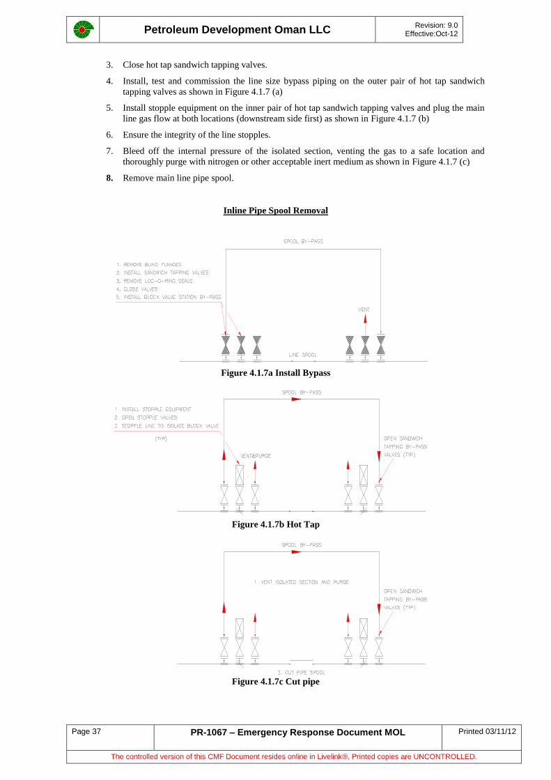
Petroleum Development Oman LLC
Revision: 9.0 Effective:Oct-12
Page 37 PR-1067 – Emergency Response Document MOL Printed 03/11/12
The controlled version of this CMF Document resides online in Livelink®. Printed copies are UNCONTROLLED.
3. Close hot tap sandwich tapping valves.
4. Install, test and commission the line size bypass piping on the outer pair of hot tap sandwich
tapping valves as shown in Figure 4.1.7 (a)
5. Install stopple equipment on the inner pair of hot tap sandwich tapping valves and plug the main
line gas flow at both locations (downstream side first) as shown in Figure 4.1.7 (b)
6. Ensure the integrity of the line stopples.
7. Bleed off the internal pressure of the isolated section, venting the gas to a safe location and
thoroughly purge with nitrogen or other acceptable inert medium as shown in Figure 4.1.7 (c)
8. Remove main line pipe spool.
Inline Pipe Spool Removal
Figure 4.1.7a Install Bypass
Figure 4.1.7b Hot Tap
Figure 4.1.7c Cut pipe
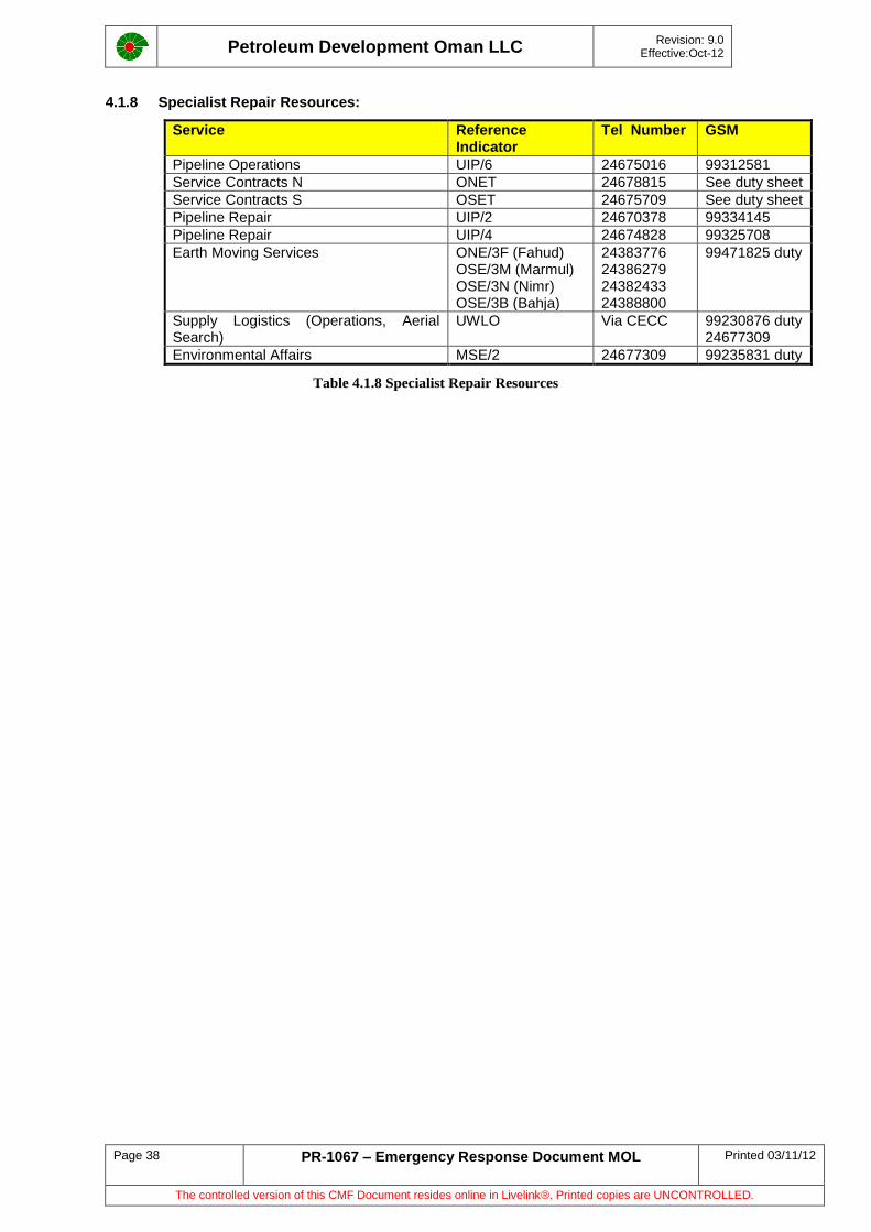
Petroleum Development Oman LLC
Revision: 9.0 Effective:Oct-12
Page 38 PR-1067 – Emergency Response Document MOL Printed 03/11/12
The controlled version of this CMF Document resides online in Livelink®. Printed copies are UNCONTROLLED.
4.1.8 Specialist Repair Resources:
Service Reference Indicator
Tel Number GSM
Pipeline Operations UIP/6 24675016 99312581
Service Contracts N ONET 24678815 See duty sheet
Service Contracts S OSET 24675709 See duty sheet
Pipeline Repair UIP/2 24670378 99334145
Pipeline Repair UIP/4 24674828 99325708
Earth Moving Services ONE/3F (Fahud) OSE/3M (Marmul) OSE/3N (Nimr) OSE/3B (Bahja)
24383776 24386279 24382433 24388800
99471825 duty
Supply Logistics (Operations, Aerial Search)
UWLO Via CECC 99230876 duty 24677309
Environmental Affairs MSE/2 24677309 99235831 duty
Table 4.1.8 Specialist Repair Resources
Petroleum Development Oman LLC
Revision: 9.0 Effective:Oct-12
Page 39 PR-1067 – Emergency Response Document MOL Printed 03/11/12
The controlled version of this CMF Document resides online in Livelink®. Printed copies are UNCONTROLLED.
5 Business Resumption
Scenarios covered under this section are:
MOL Pipeline
MOL Booster Stations
MOL crude stabilisation unit (NOCS)
5.1 Pipeline Recovery
5.1.1 Repair
Immediate repair within the capabilities of the interior Asset Team (e.g. clamp repair) will be executed by the Asset Engineering team, materials can be obtained from logistics stores. Authorisation from UIPT (UIP/4) for release from the emergency stock may be required.
Larger scale repair (outside the capabilities of the Asset Team) will be executed by the Asset Engineering team, supported by a team of coastal based pipeline engineers. This team will be formed on an 'ad hoc' basis by the UIP or the LEBC on duty. Materials will be obtained from the warehouse. Authorisation from UIP (UIP/4) for release from emergency stock may be required. If required special materials may be obtained under the Pipeline Emergency Contract.)
The repair procedure is detailed in the Pipeline Emergency Repair Manual GU 379. Pipeline repair materials (Emergency Stock) are stored at Marmul, Fahud and MaF.
On an extended repair it will be necessary to provide facilities for the emergency response personnel. Toilet and washing facilities and possibly one of the portable telecommunications trailers should be sent to site. A large amount of PPE may also be required by repair personnel.
5.1.2 Clean Up and Waste Disposal
If any wadi or aquifer has been contaminated, a thorough follow up should be made to avoid any third party incidents. UIPT is accountable for managing any response. In extreme cases an environmental impact assessment may be justified. Removal with vacuum trucks is the simplest method but care in positioning the trucks is required.
Cleanup
Cleanup depends on the amount spilled and the type of soil condition in the spill area.
Wadis in particular will be very difficult to clean as the oil will seep deep into the substrata
Cleaning with water hoses could be effective
Percolating water underneath the oil has also been proven effective under certain conditions
When no more oil can be sucked up by vacuum truck or other pumps, the soil must be cleaned or removed. This can be done mechanically and/or manually depending on the location
Temporary storage on the site can be provided by lining pits with plastic. Liners for pits can be obtained from the offshore oil spill equipment at the MaF port area and supply stores
The strategy for clean up is to be discussed and agreed by the Environmental Advisor MSE/2. (for more information refer to:)
Guidelines for Site Protection : CP 126
Cleanup and Waste Disposal : PR1084
Waste Disposal
Dispose off the recovered oil according to applicable procedures
Waste Management Manual : SP1009
Petroleum Development Oman LLC
Revision: 9.0 Effective:Oct-12
Page 40 PR-1067 – Emergency Response Document MOL Printed 03/11/12
The controlled version of this CMF Document resides online in Livelink®. Printed copies are UNCONTROLLED.
Deliver spilled oil to the MaF tank farm emulsion plant or an interior location (Fahud) whichever is most convenient.
Recovered oil in liquid form can be loaded in vacuum trucks and sent to a reception facility. This is MaF Tank Farm or Fahud whichever is closest
Contaminated sand with oil pebbles cannot be despatched to the tank farm, but should be sent to the interior for soil rehabilitation or to the nearest incinerator
5.2 Booster Station Recovery
5.2.1 Booster Stations Generic
Fuel gas supplies are a hazard, and during an emergency should be carefully considered as an escalation possibility.
Gas: Leaks within a booster station will normally be inside the fenced area, however, gas testing should be used to determine the danger area in and outside of the fence and establish if external site access control or road blocks are required.
H2S: Even though all Booster stations are classed as no/low H2S; ie <50ppm of H2S, in the event of a major oil leak, full BA must be worn with BA procedures implemented.
Staff mobilised to the area must be warned of the leak and should not be allowed on site without proper monitoring and protective equipment (in accordance with the Company H2S policy). Gas testing should be maintained to confirm safe working conditions.
Station Bypass: In the event of a station trip or shut-down crude oil will flow via the by-pass.
If the station Operator deems necessary the MOL should be shut-down by informing CCR Marmul Operator. Only when the risk of escalation is over and the situation under control should the damaged sections should be positively isolated and the bypass used.
If safe to do so, mobilise crews of operators equipped with "Amplitorque" hydraulic units to operate the block valves [as in the MOL Pipeline Emergency contingency Section 4.2]. It is normally not possible to depressurize the MOL due to the large volumes involved, and the absence of suitable drain systems.
The station bypass will allow reduced export rates.
To enable a booster station to operate on bypass, the upstream pumping facility must export at a higher pressure in order to reach the next point downstream of the bypassed station. This higher pressure is restricted by the operating envelope of the upstream pumps, and also by the safe working pressure of the MOL. This latter point is critical as in certain sections of the MOL the line may have been derated due to internal corrosion. The availability of pump units in the other stations will also restrict the ability to respond with additional capacity.
In addition to the upstream facility having to increase discharge pressure, the next downstream facility w.r.t the bypassed station, may have to operate at a lower suction pressure. This will in turn reduce the efficiency of that station, and may cause consequential problems. Close cooperation between the controlling units of the various sectors of the MOL are required to maintain a balance on the MOL and reduce overall deferment.
ROP
The scenarios discussed in this section are normally contained within the area of the Booster Station, environmental impact will be restricted as the stations are remote from any sensitive areas. The exception to this are the ROP stations adjacent to each Booster Station. ROP stations, and the vehicles, should be considered as a possible source of ignition. The security focal point for any LECC team must inform ROP of any emergency at Booster stations
5.2.2 Sahma Booster Station
For any emergency involving Sahma booster station, Petrogas should be informed. Marmul CCR has the contact numbers.
Petroleum Development Oman LLC
Revision: 9.0 Effective:Oct-12
Page 41 PR-1067 – Emergency Response Document MOL Printed 03/11/12
The controlled version of this CMF Document resides online in Livelink®. Printed copies are UNCONTROLLED.
Sahma Booster Station also contains a "Flow Measuring and Meter Proving Skid" owned and operated by a third party. This is used for fiscal purposes to measure that company's crude export from the Petrogas Sahma Field, which joins the MOL at Sahma Booster Station.
5.2.3 Utility Failure in Booster Stations
Instrument Air
Failure of the air compressor will shut down the Booster stations.
The Instrument Air Compressor package is electrically driven and would initiate a "Low Instrument Air Pressure" shut down on most process equipment in the event of an electrical failure.
Electrical Power
All booster stations are connected to the Government and/or PDO electricity grids.
At Nahada-1, Nahada-2, Sahma and Hubara there are no working gas powered back up generators available. There are no black start generators available either.
The MOL booster pumps are driven by a combination of individual fuel gas fired Ruston Turbines and Electrical Pumps. (Nahada-1 = Electrical only (with Gas Turbines presently being de-commissioned), Nahada-2 = Electrical Pumps only, Sahma = Gas Turbines with 1 electrical pump on stand-by, Hubara = 3 Electrical Pumps only).
Fire Detection
Fire detection in a Booster Stations will cause a shutdown and trip all pumps. The layout of the Booster Stations is such that when a station trips, it trips to bypass mode; ie the inlet and outlet ESD valves close (fail on close) and the station bypasses via the NRV’s. These ESD valves are normal pneumatic/spring actuator ball valves with a fail safe position regardless of utility failure.
Individual Booster Pump Isolation
The ESD isolation valves are situated on the common suction and discharge headers, close to the booster pumps. Individual isolation of each booster pump is via a MOV gate valve on the suction and discharge line to the pumps. The MOV valves provide isolation between individual pumps, and would in theory isolate a ruptured suction or discharge line. In practice however, the MOV's are motorised valves dependent on electrical power and do not have a fail safe position. In the event of a fire, shutdown of the running generator would leave the MOVs of the running pumps open. The MOVs do have a hand wheel for manual operation, however these may be inaccessible in the event of a fire.
Sahma, Hubara and Nahada have automatic station bypass which make use of check-valves. They have automatic ESD valves to protect the facilities.
5.3 NOCS Unit Recovery
It should be noted that NOCS is the sole responsibility of the Northern Asset. As such any emergency work should be managed and carried out by ONO. However, as it plays a crucial role in the stabilisation of MOL crude the general guidelines have been included below for information only.
5.3.1 NOCS Station Generic
It should be noted that at time of print QA NOCS does not function and is not anticipated to be put into use in the future. The following is therefore applicable only for Fahud NOCS.
Gas: Leaks within the NOCS will normally be inside the fenced area, however, gas testing should be used to determine the danger area in and outside of the fence and establish if external site access control or road blocks are required. Gas testing should be maintained at all times to confirm ongoing safe working conditions.
H2S: The Crude Stabilisation Units are classed as sour; i.e. >50ppm of H2S, in the event of a major oil leak, full BA must be worn and BA procedures implemented. Staff mobilised to the area must be warned of the leak and should not be allowed on site without proper monitoring and protective equipment (in accordance with the Company H2S policy).
Fahud Station Bypass:
Petroleum Development Oman LLC
Revision: 9.0 Effective:Oct-12
Page 42 PR-1067 – Emergency Response Document MOL Printed 03/11/12
The controlled version of this CMF Document resides online in Livelink®. Printed copies are UNCONTROLLED.
The Fahud Crude Stabilisation Plant is capable of being bypassed, allowing upstream and downstream facilities to maintain a reduced throughput through the station bypass. Use of the CSU bypass is dependent on the technical integrity of the bypass following damage to other sections of the CSU.
Blending mode is an emergency recovery operation in the event of prolonged outage of all three vacuum separation trains at Fahud NOCS. It enables export of the Yibal and Lekhwair crude with high True Vapour Pressure [TVP] oil. This is achieved through controlled blending at reduced flowrates with stable crude from both Fahud MLPS and the Qarn Alam plant. Bypassing Fahud NOCS is not a trivial process and requires significant mechanical / process intervention.
Even though a CSU has tripped or been shutdown, it may still be possible to bypass the MOL around the plant. If the bypass and associated equipment are considered to be safe, and not threatened or damaged by a fire or explosion, they may be used.
If there is a serious risk of escalation, which prevents use of the bypass, the resources required to normalise this situation should be urgently identified. Within a short space of time it will be required to shut in production facilities upstream of the CSU, due to high tank levels.
Operating a CSU on bypass, requires close cooperation between the controlling units of the various sectors of the MOL, to maintain a balance on the MOL will reduce overall deferment.
ROP As the scenarios discussed here are normally contained within the area of the CSU, environmental impact will be restricted and remote from any sensitive area. The one exception to this being the ROP stations adjacent to each MPSNOCS facility. These ROP stations, and vehicles, should be considered as a possible source of ignition.
5.3.2 Utility Failure in MOL Crude Stabilisation Unit.
Electrical Failure
The CSUs are connected to the PDO electrical supply grid.
An electrically driven Instrument Air Compressor controls most of the process functions in the CSU. Electrical failure would initiate a "Low Instrument Air Pressure" shut down on most process equipment.
Back up batteries are for emergency lighting and instrumentation only.
Fire Detection
Fire detection on a CSU will cause a shutdown of the running equipment. The normal layout of the CSU is such that when the plant trips, the inlet and outlet ESD valves close (fail close). These ESD valves are normal pneumatic/spring actuator ball valves with a failsafe position regardless of utility failure.
The ESD isolation valves are on the common inlet and outlet headers, close to the plant. The individual isolation of each part of the system is via a MOV gate valve on the inlet and outlet line to each system. These MOV valves provide isolation between individual components, and would in theory isolate a ruptured suction or discharge line from the other components. In practice however, the MOV's are motorised valves dependent on electrical power to move, and thus do not have a failsafe position. In the event of a major fire, shutdown of the electrical supply grid would leave the MOV's of the running equipment open. The MOV's do have a hand wheel for manual operation, which would probably be inaccessible in the event of a fire.
Loss of electrical power, will aggravate the situation by preventing individual isolation of each component. If one of the isolation ESD's is passing, failure of the individual MOV gate valves to close due to electrical failure could cause escalation of an emergency.
Petroleum Development Oman LLC
Revision: 9.0 Effective:Oct-12
Page 43 PR-1067 – Emergency Response Document MOL Printed 03/11/12
The controlled version of this CMF Document resides online in Livelink®. Printed copies are UNCONTROLLED.
Appendix A : Glossary Abbreviations:
BA Breathing Apparatus BVS Block Valve Station CCR Central Control Room CECC Central Emergency Coordination Centre CRO Control Room Operator CSU Crude Stabilisation Unit DD Duty Director DEP Design and Engineering Practices ERC Emergency Radio Caravan ERD Engineering Reference Documents ERP Emergency Response Plan ESD FBE
Emergency Shut Down Fusion Bonded Epoxy
GGS Government Gas System HSE Health, Safety & Environment LEBC Local Emergency Base Controller LECC Local Emergency Control Centre LEL Lower Explosive Limit MaF Mina al Fahal MLPS Main Line Pumping Station MOL Main Oil Line MOG Ministry of Oil and Gas MMPS MPS
Marmul Main Production Station Main Production Station
MRME&WR Ministry of Regional Municipalities, Environment and Water Resources
MSE HSE Services NOCS North Oman Crude Stabilisation OSC On Scene Commander PFAT / PFAM Product Flow Asset Team / Product Flow Asset Manager PRA Pressure Reduction Area RAFO Royal AirForce of Oman ROW Right of Way (Road along the Main Oil Line) S/D Shut Down SI Standing Instruction TVP True Vapour Pressure

Petroleum Development Oman LLC
Revision: 9.0 Effective:Oct-12
Page 44 PR-1067 – Emergency Response Document MOL Printed 03/11/12
The controlled version of this CMF Document resides online in Livelink®. Printed copies are UNCONTROLLED.
Petroleum Development Oman LLC
Revision: 9.0 Effective:Oct-12
Page 45 PR-1067 – Emergency Response Document MOL Printed 03/11/12
The controlled version of this CMF Document resides online in Livelink®. Printed copies are UNCONTROLLED.
Appendix B : Telephone List
The following list is not conclusive and should be used as a guide only. The full list of emergency numbers and out of office numbers / GSM is available via LECC and CECC duty teams. This is updated and issued on a weekly basis by the UIC department.
PDO Numbers
Terminal Personnel Telephone Numbers:
Job Title Ref. Ind.
Office GSM Pager
Head Of Infrastructure Terminal & Offshore Ops
UIT 77232 99426883
Area HSE Adviser UIC 73600
Chief Fire Officer UIT/5 77981 9124141
Marine Operations Snr Supv UIT/4 77768 99376046
Berthing Master(s) UIT/41 77231 99376048 99124075
Terminal Operations. UIT/3 75328 99417814 99124137
Terminal Operations UIT/31 77233 99216102 9124080
Mech. Maint. Supv. UIT/1 77637 99310145 9124139
Instr./Electr. Supv UIT/2 78103 99241431 9124048
PDO Specialist Resources:
Service Ref. Ind. Phone
PDO Security UIC/X (on duty) 24674858 / 6643 99472041
Human Resources, Police Liaison HCR/1F (Fahud) HCR/2M (Marmul)
24384219 24386257
Medical Officer MCO/1N MCO/1S
24384245 24386439
Environmental Affairs MSE/2 (MaF) 24678433
Environmental Advisor MSE/21 MSE/22
24675875 24677832
Head Logistics UWLO/1 (Coast) UWLS (North) UWL/3 (South)
24678865 24382526 24386014
Supply Operations Cargo Haulage UWL/11 (Coast) UWLN/1 (North) UWLS/1 (South)
24678850 24384253 24382629
Supply Operations Warehousing / Materials UWLN/2 (N-Fahud) UWLS/2 (S-Marmul)
24384392 24386289
Supply Operations, Transport (Air/Land) UWLO/3 (Coast) UWLN/3 (N-Fahud) UWLS/3 (S-Marmul)
24675094 24384426 24386642
For Coastal Supply Operations, the duty person can be contacted on pager no. 99471825
Head Construction / Earthmoving Services ONE/3F (Fahud) OSE/3M (Marmul) OSE/3N (Nimr) OSE/3B (Bahja)
24383667 24386279 24382433 24388800
Pipeline Maintenance UIP/4 UIP/45N (Fahud) UIP/45M (Marmul) UIP/45Q (Q.Alam)
24674828 24383702 24386512/ 6512 24385844
Pipeline Materials and Corrosion UEOC/31 24673240
Petrogas
Sahma Control Room Tel : 24388799 fax : 24388786
Petroleum Development Oman LLC
Revision: 9.0 Effective:Oct-12
Page 46 PR-1067 – Emergency Response Document MOL Printed 03/11/12
The controlled version of this CMF Document resides online in Livelink®. Printed copies are UNCONTROLLED.
Government Telephone Numbers (update UIP/33 June 2008)
Ministries
Ministry of Oil and Gas
Switchboard 24640555 / 24640556
Facsimile 246691046
H.E The Minister's Office 24640500
H.E The Under Secretary, 24640666 / 24603490
Ministry of Regional Municipalities, Environment & Water Resources
Municipalities
Switch board 24692550
Facsimile 24753027
Water Resources
D.G. of Water Resources 246111222
Ministry of Environment & Climate Affairs
D.G. of Env. Affairs 24404814 Office
(Mohammed Abdullah Al-Moharami)
Switch board 24404500
Facsimile 24692462
Director of H.E. The Minister's Office 24602072
Muscat Municipality
Switch board 24753000
Facsimile 24753027
Office of the President 24706653
Deputy Chairman 24796033
Public Organisation For Electricity & Water
Switch board 24611100
Facsimile 24699183
D.G. Electrical 24661110
Facsimile 24605367
D.G. Water 24697386
Facsimile 24607076
Police: full details can be obtained via UIC/51
Oil and Gas Installation Operations Manager 99034444 (Major Saif al Kayumi)
Police Head Quarters 24560099 Fax: 24563352
Royal Oman Police Muscat Region 7222, 24560021
Bausher Police Station 24600099
Bidbid Police Station 25360099
Sumail Police Station 25350099
Izki Police Station 25340099
Muscat Area
Petroleum Development Oman LLC
Revision: 9.0 Effective:Oct-12
Page 47 PR-1067 – Emergency Response Document MOL Printed 03/11/12
The controlled version of this CMF Document resides online in Livelink®. Printed copies are UNCONTROLLED.
Watayah Police Station 24566538
AlAlam 24736611
Matrah 24712211/24712212
Ruwi 24701099
AlAmrat 24875999
Boushar 24600099
Sidab 72437415 / 24737821/822
Quriat 24845555
AlSeeb 24420099
AlBatinah Region
Suhar police Station 26840099/26840919
Barka 26882099 Fax: 26882109
Al Dhahira Region
Ibri Police Station 25689099/25689218
Fahud 24384222
Lekhwair 24381837
Yibal 24381202
Interior Region
Nizwa Police station 25425099/2542522
Sumayil 25350099/2350213
Bid Bid 25360099
Izki 25340099/25342099
Nahada 24384495
Al Wosta Region
Haima Police Station 23434211
Qarn Alam 24385559
Rima 24382272
Nimr 24382444/23382272
Bahja 24388963
Hubara 24388564
Al Jazer 99238814
Al Duqum 25427088 / 25427188
Dhofar Region
Marmul 24386222
Shaleem 23200399
Thamreet 23279099

Petroleum Development Oman LLC
Revision: 9.0 Effective:Oct-12
Page 48 PR-1067 – Emergency Response Document MOL Printed 03/11/12
The controlled version of this CMF Document resides online in Livelink®. Printed copies are UNCONTROLLED.
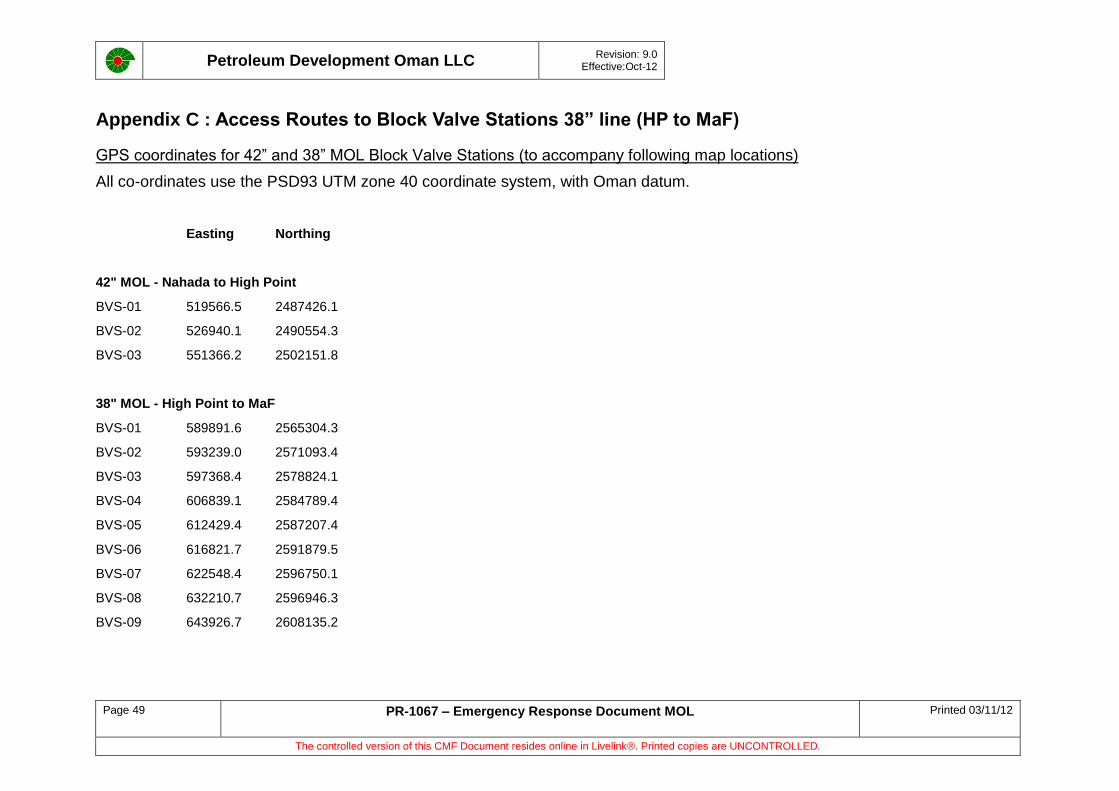
Petroleum Development Oman LLC
Revision: 9.0 Effective:Oct-12
Page 49 PR-1067 – Emergency Response Document MOL Printed 03/11/12
The controlled version of this CMF Document resides online in Livelink®. Printed copies are UNCONTROLLED.
Appendix C : Access Routes to Block Valve Stations 38” line (HP to MaF)
GPS coordinates for 42” and 38” MOL Block Valve Stations (to accompany following map locations)
All co-ordinates use the PSD93 UTM zone 40 coordinate system, with Oman datum.
Easting Northing
42" MOL - Nahada to High Point
BVS-01 519566.5 2487426.1
BVS-02 526940.1 2490554.3
BVS-03 551366.2 2502151.8
38" MOL - High Point to MaF
BVS-01 589891.6 2565304.3
BVS-02 593239.0 2571093.4
BVS-03 597368.4 2578824.1
BVS-04 606839.1 2584789.4
BVS-05 612429.4 2587207.4
BVS-06 616821.7 2591879.5
BVS-07 622548.4 2596750.1
BVS-08 632210.7 2596946.3
BVS-09 643926.7 2608135.2
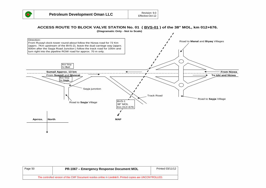
Petroleum Development Oman LLC
Revision: 9.0 Effective:Oct-12
Page 50 PR-1067 – Emergency Response Document MOL Printed 03/11/12
The controlled version of this CMF Document resides online in Livelink®. Printed copies are UNCONTROLLED.
ACCESS ROUTE TO BLOCK VALVE STATION No. 01 ( BVS-01 ) of the 38" MOL, km 012+676.(Diagramatic Only - Not to Scale)
Road to Manal and Biyaq Villages
Sumail Approx. 13 km From Nizwa
From Suamil and Muscat To Izki and Nizwa
Sayja junction
Track Road
Road to Sayja Village
Road to Sayja Village
Aprrox. North MAF
BVS-1
38" MOL
Km 012+676
Direction:
From Rusayl clock-tower round-about follow the Nizwa road for 72 Km
(apprx. 7Km upstream of the BVS-2), leave the dual carriege way (apprx.
600m after the Sayja Road Junction ) follow the track road for 100m and
turn right into the pipeline ROW road for approx. 70 m only.
Bus Stop
for Buri
Bus Stop
for Sayja
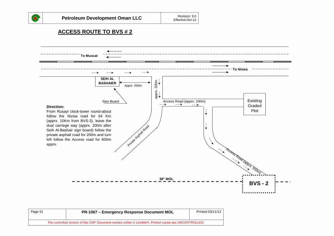
Petroleum Development Oman LLC
Revision: 9.0 Effective:Oct-12
Page 51 PR-1067 – Emergency Response Document MOL Printed 03/11/12
The controlled version of this CMF Document resides online in Livelink®. Printed copies are UNCONTROLLED.
ACCESS ROUTE TO BVS # 2
apprx
. 200m
Access Road (apprx. 100m)
Priv
ate
Asp
halt Roa
d
Access Road (apprx. 500m)
38" MOL
BVS - 2
Existing
Graded
Plot
SEIH AL
BASHAIER
To Nizwa
To Muscat
Apprx. 200m
Sign Board
Direction:
From Rusayl clock-tower round-about
follow the Nizwa road for 64 Km
(apprx. 10Km from BVS-3), leave the
dual carriege way (apprx. 200m after
Seih Al-Bashair sign board) follow the
private asphalt road for 200m and turn
left follow the Access road for 600m
apprx.
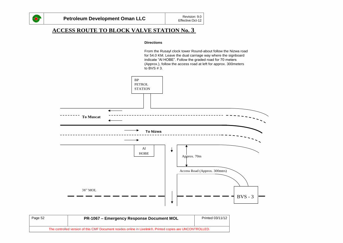
Petroleum Development Oman LLC
Revision: 9.0 Effective:Oct-12
Page 52 PR-1067 – Emergency Response Document MOL Printed 03/11/12
The controlled version of this CMF Document resides online in Livelink®. Printed copies are UNCONTROLLED.
ACCESS ROUTE TO BLOCK VALVE STATION No. 3
Directions
From the Rusayl clock tower Round-about follow the Nizwa road
for 54.0 KM. Leave the dual carriage way where the signboard
indicate “Al HOBE”. Follow the graded road for 70 meters
(Approx.), follow the access road at left for approx. 300meters
to BVS # 3.
To Nizwa
Al
HOBE
38” MOL
To Muscat
Access Road (Approx. 300mtrs)
BP
PETROL
STATION
BVS - 3
Approx. 70m
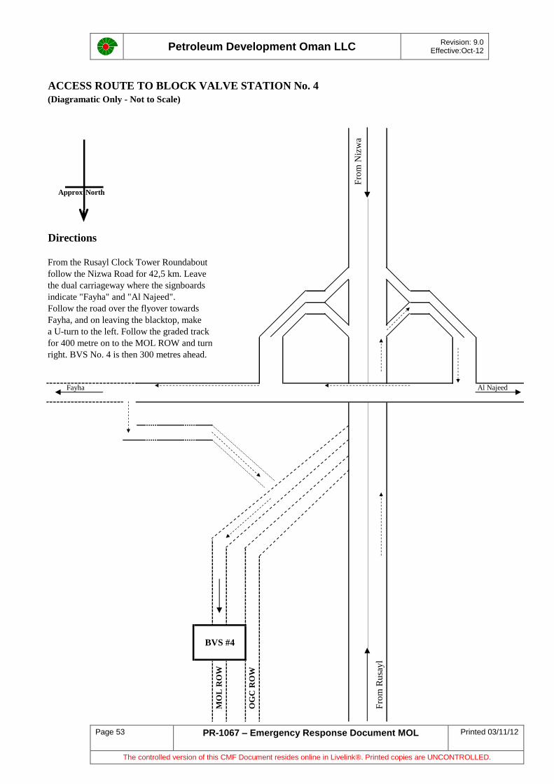
Petroleum Development Oman LLC
Revision: 9.0 Effective:Oct-12
Page 53 PR-1067 – Emergency Response Document MOL Printed 03/11/12
The controlled version of this CMF Document resides online in Livelink®. Printed copies are UNCONTROLLED.
ACCESS ROUTE TO BLOCK VALVE STATION No. 4
(Diagramatic Only - Not to Scale)
Fro
m N
izw
a
Approx North
Directions
From the Rusayl Clock Tower Roundabout
follow the Nizwa Road for 42,5 km. Leave
the dual carriageway where the signboards
indicate "Fayha" and "Al Najeed".
Follow the road over the flyover towards
Fayha, and on leaving the blacktop, make
a U-turn to the left. Follow the graded track
for 400 metre on to the MOL ROW and turn
right. BVS No. 4 is then 300 metres ahead.
Fayha Al Najeed
MO
L R
OW
OG
C R
OW
Fro
m R
usa
yl
BVS #4
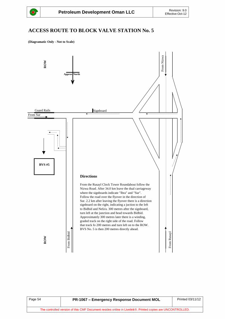
Petroleum Development Oman LLC
Revision: 9.0 Effective:Oct-12
Page 54 PR-1067 – Emergency Response Document MOL Printed 03/11/12
The controlled version of this CMF Document resides online in Livelink®. Printed copies are UNCONTROLLED.
ACCESS ROUTE TO BLOCK VALVE STATION No. 5
(Diagramatic Only - Not to Scale)R
OW
Fro
m N
izw
a
Approx North
Guard Rails Signboard
From Sur
Directions
From the Rusayl Clock Tower Roundabout follow the
Nizwa Road. After 34.0 km leave the dual carriageway
where the signboards indicate "Ibra" and "Sur".
Follow the road over the flyover in the direction of
Sur. 2.2 km after leaving the flyover there is a direction
signboard on the right, indicating a juction to the left
to Bidbid and Nefa'a. 300 metres after the signboard,
turn left at the junction and head towards Bidbid.
Approximately 300 metres later there is a winding,
graded track on the right side of the road. Follow
that track fo 200 metres and turn left on to the ROW.
BVS No. 5 is then 200 metres directly ahead.
RO
W
Fro
m B
idb
id
Fro
m R
usa
yl
BVS #5
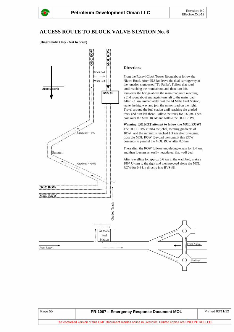
Petroleum Development Oman LLC
Revision: 9.0 Effective:Oct-12
Page 55 PR-1067 – Emergency Response Document MOL Printed 03/11/12
The controlled version of this CMF Document resides online in Livelink®. Printed copies are UNCONTROLLED.
ACCESS ROUTE TO BLOCK VALVE STATION No. 6
(Diagramatic Only - Not to Scale)
OG
C R
OW
MO
L R
OW
DirectionsWadi Bed
From the Rusayl Clock Tower Roundabout follow the
Wadi Bed Nizwa Road. After 25.8 km leave the dual carriageway at
the junction signposted "To Fanja". Follow that road
Approx North until reaching the roundabout, and then turn left.
BVS #6 Pass over the bridge above the main road until reaching
a 2nd roundabout and again turn left to the main road.
After 5.1 km, immediately past the Al Maha Fuel Station,
leave the highway and join the minor road on the right.
Travel around the fuel station until reaching the graded
track and turn left there. Follow the track for 0.6 km. Then
pass over the MOL ROW and follow the OGC ROW.
Warning: DO NOT attempt to follow the MOL ROW!
The OGC ROW climbs the jebel, meeting gradients ofGradient > - 6% 10%+, and the summit is reached 1.3 km after diverging
from the MOL ROW. Beyond the summit this ROW
descends to parallel the MOL ROW after 0.5 km.
Thereafter, the ROW follows undulating terrain for 2.4 km,
Summit and then it enters an easily negotiated, flat wadi bed.
After travelling for approx 0.6 km in the wadi bed, make a
Gradient > +10% 180* U-turn to the right and then proceed along the MOL
ROW for 0.4 km directly into BVS #6.
OGC ROW
MOL ROW
Gra
ded
Tra
ck
From Nizwa
From Rusayl
F'm Fanja
Station
Al Maha
Fuel
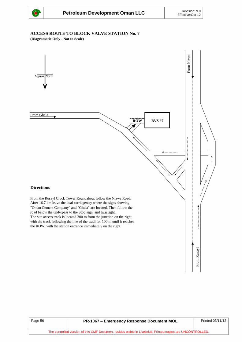
Petroleum Development Oman LLC
Revision: 9.0 Effective:Oct-12
Page 56 PR-1067 – Emergency Response Document MOL Printed 03/11/12
The controlled version of this CMF Document resides online in Livelink®. Printed copies are UNCONTROLLED.
ACCESS ROUTE TO BLOCK VALVE STATION No. 7
(Diagramatic Only - Not to Scale)
Fro
m N
izw
a
Approx North
From Ghala
Directions
From the Rusayl Clock Tower Roundabout follow the Nizwa Road.
After 16.7 km leave the dual carriageway where the signs showing
"Oman Cement Company" and "Ghala" are located. Then follow the
road below the underpass to the Stop sign, and turn right.
The site access track is located 300 m from the junction on the right,
with the track following the line of the wadi for 100 m until it reaches
the ROW, with the station entrance immediately on the right.
Fro
m R
usa
yl
ROW BVS #7
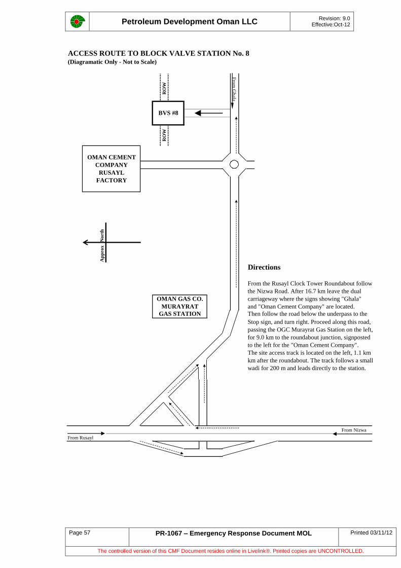
Petroleum Development Oman LLC
Revision: 9.0 Effective:Oct-12
Page 57 PR-1067 – Emergency Response Document MOL Printed 03/11/12
The controlled version of this CMF Document resides online in Livelink®. Printed copies are UNCONTROLLED.
ACCESS ROUTE TO BLOCK VALVE STATION No. 8(Diagramatic Only - Not to Scale)
RO
WF
rom
Gh
ala
RO
W
No
rth
Ap
pro
x
Directions
From the Rusayl Clock Tower Roundabout follow
the Nizwa Road. After 16.7 km leave the dual
carriageway where the signs showing "Ghala"
and "Oman Cement Company" are located.
Then follow the road below the underpass to the
Stop sign, and turn right. Proceed along this road,
passing the OGC Murayrat Gas Station on the left,
for 9.0 km to the roundabout junction, signposted
to the left for the "Oman Cement Company".
The site access track is located on the left, 1.1 km
km after the roundabout. The track follows a small
wadi for 200 m and leads directly to the station.
From Nizwa
From Rusayl
BVS #8
OMAN CEMENT
COMPANY
RUSAYL
FACTORY
OMAN GAS CO.
MURAYRAT
GAS STATION
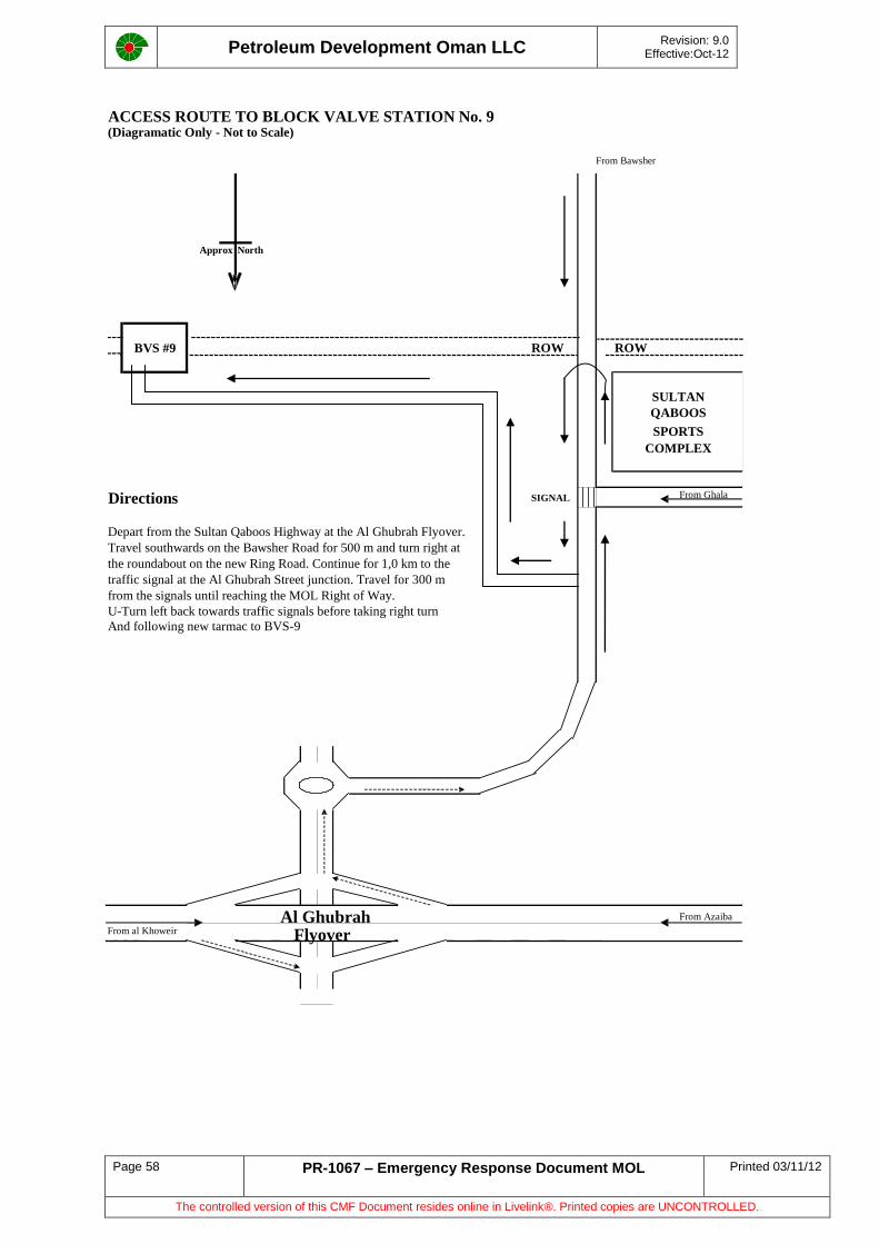
Petroleum Development Oman LLC
Revision: 9.0 Effective:Oct-12
Page 58 PR-1067 – Emergency Response Document MOL Printed 03/11/12
The controlled version of this CMF Document resides online in Livelink®. Printed copies are UNCONTROLLED.
ACCESS ROUTE TO BLOCK VALVE STATION No. 9 (Diagramatic Only - Not to Scale)
From Bawsher
Approx North
ROW ROW
Directions SIGNAL From Ghala
Depart from the Sultan Qaboos Highway at the Al Ghubrah Flyover. Travel southwards on the Bawsher Road for 500 m and turn right at the roundabout on the new Ring Road. Continue for 1,0 km to the traffic signal at the Al Ghubrah Street junction. Travel for 300 m from the signals until reaching the MOL Right of Way. U-Turn left back towards traffic signals before taking right turn
And following new tarmac to BVS-9
From Azaiba From al Khoweir
SPORTS COMPLEX
BVS #9
SULTAN QABOOS
Al Ghubrah Flyover
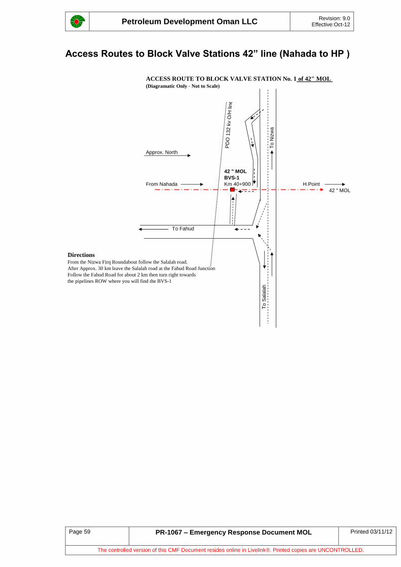
Petroleum Development Oman LLC
Revision: 9.0 Effective:Oct-12
Page 59 PR-1067 – Emergency Response Document MOL Printed 03/11/12
The controlled version of this CMF Document resides online in Livelink®. Printed copies are UNCONTROLLED.
Access Routes to Block Valve Stations 42” line (Nahada to HP )
ACCESS ROUTE TO BLOCK VALVE STATION No. 1 of 42" MOL
(Diagramatic Only - Not to Scale)
PD
O 1
32 k
v O
/H lin
e
To
Niz
wa
Approx. North
42 " MOL
BVS-1
From Nahada Km 40+900 H.Point
42 " MOL
To Fahud
DirectionsFrom the Nizwa Firq Roundabout follow the Salalah road.
After Approx. 30 km leave the Salalah road at the Fahud Road Junction
Follow the Fahud Road for about 2 km then turn right towards
the pipelines ROW where you will find the BVS-1
To
Sa
lala
h
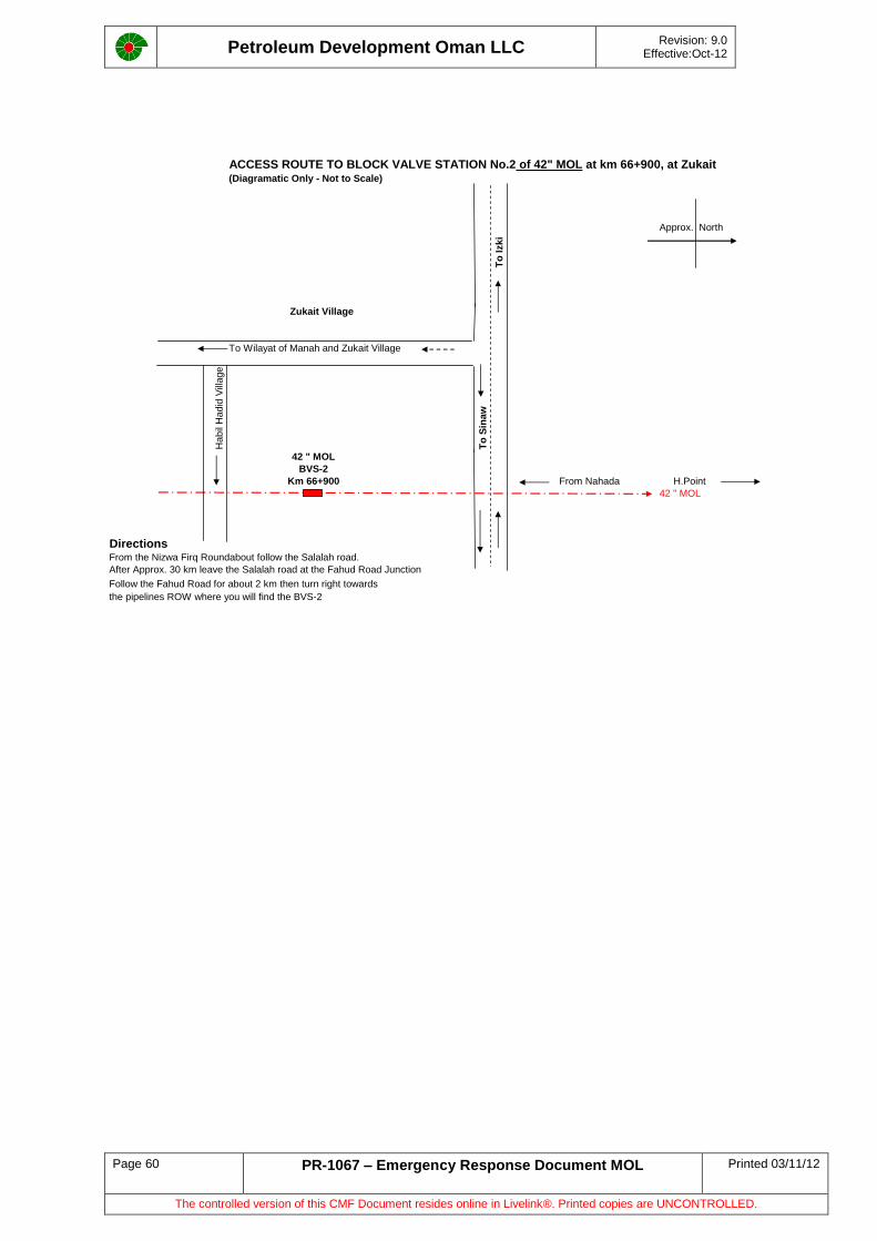
Petroleum Development Oman LLC
Revision: 9.0 Effective:Oct-12
Page 60 PR-1067 – Emergency Response Document MOL Printed 03/11/12
The controlled version of this CMF Document resides online in Livelink®. Printed copies are UNCONTROLLED.
ACCESS ROUTE TO BLOCK VALVE STATION No.2 of 42" MOL at km 66+900, at Zukait(Diagramatic Only - Not to Scale)
Approx. North
To
Izk
i
Zukait Village
To Wilayat of Manah and Zukait Village
Ha
bil
Hadid
Vill
age
To
Sin
aw
42 " MOL
BVS-2
Km 66+900 From Nahada H.Point
42 " MOL
DirectionsFrom the Nizwa Firq Roundabout follow the Salalah road.
After Approx. 30 km leave the Salalah road at the Fahud Road Junction
Follow the Fahud Road for about 2 km then turn right towards
the pipelines ROW where you will find the BVS-2
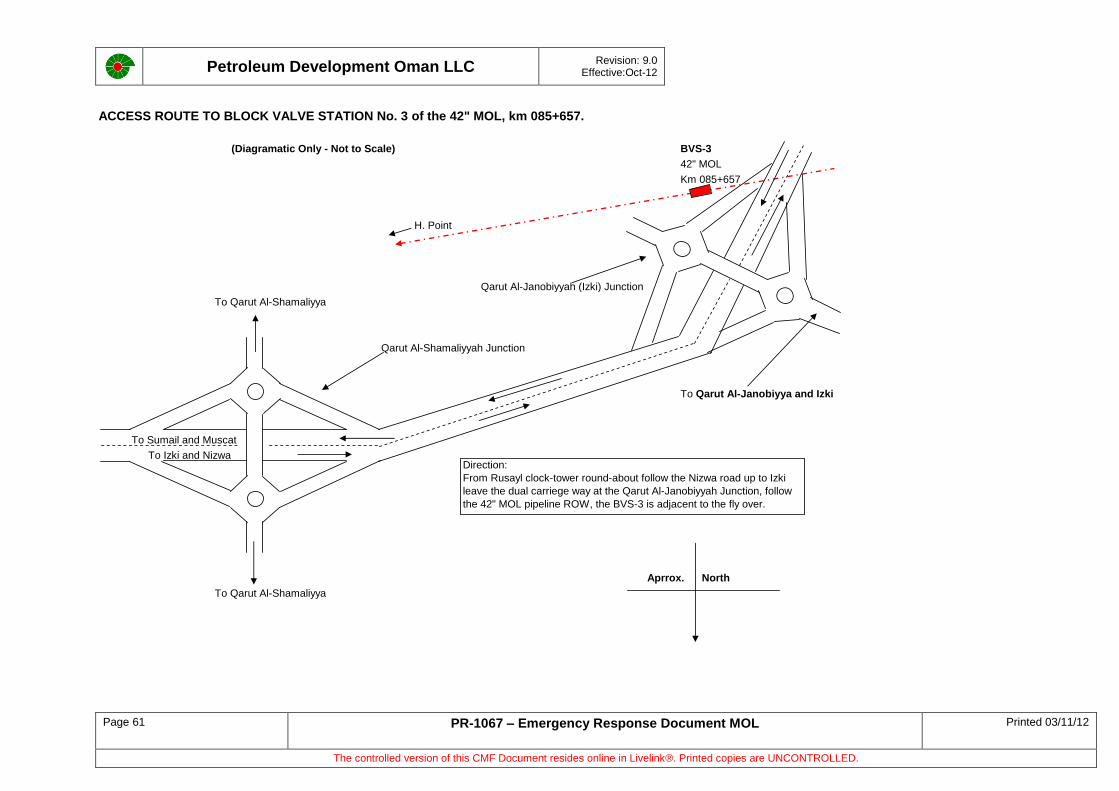
Petroleum Development Oman LLC
Revision: 9.0 Effective:Oct-12
Page 61 PR-1067 – Emergency Response Document MOL Printed 03/11/12
The controlled version of this CMF Document resides online in Livelink®. Printed copies are UNCONTROLLED.
ACCESS ROUTE TO BLOCK VALVE STATION No. 3 of the 42" MOL, km 085+657.
(Diagramatic Only - Not to Scale) BVS-3
42" MOL
Km 085+657
H. Point
Qarut Al-Janobiyyah (Izki) Junction
To Qarut Al-Shamaliyya
Qarut Al-Shamaliyyah Junction
To Qarut Al-Janobiyya and Izki
To Sumail and Muscat
To Izki and Nizwa
Aprrox. North
To Qarut Al-Shamaliyya
Direction:
From Rusayl clock-tower round-about follow the Nizwa road up to Izki
leave the dual carriege way at the Qarut Al-Janobiyyah Junction, follow
the 42" MOL pipeline ROW, the BVS-3 is adjacent to the fly over.
Petroleum Development Oman LLC
Revision: 9.0 Effective:Oct-12
Page 62 PR-1067 – Emergency Response Document MOL Printed 03/11/12
The controlled version of this CMF Document resides online in Livelink®. Printed copies are UNCONTROLLED.
Petroleum Development Oman LLC
Revision: 9.0 Effective:Oct-12
Page 63 PR-1067 – Emergency Response Document MOL Printed 03/11/12
The controlled version of this CMF Document resides online in Livelink®. Printed copies are UNCONTROLLED.
Appendix D: Special Case Study. Learnings from Nahada - MAF
42” Nahada – High Point and 38” High Point – MAF Potential Impact and Emergency Preparedness.
In May 2005 a special paper has been written taking into account recent learnings from recent real emergencies. It should act as a guide for any emergency on the 42” or 38” section of MOL from Nahada to High Point to MaF. The following document is as written in 2005 with some recent updates in blue.
D1 Background
The 42”and the 38” Main Oil Line sections from Nahada to High Point and from High point to MAF constitute the most critical segment of the Main Oil Line as 100% of Oman crude oil production is transported through this segment.
The 38” Main Oil Line from High Point to MAF has been in operation since 1986. During the last 19 years of its existence, the topography and landscape of the areas adjoining the pipeline route/alignment has undergone substantial changes due to urbanization and development along the pipeline corridor particularly towards MAF end.
Loss of containment in this segment of the MOL is potentially very serious; especially because of the proximity to human habitation and the impact on production.
Automated overpressure protection/safeguarding facilities exist on the main oil line segment notably the Emergency Shutdown systems (at MAF and at Nahada booster station) and the relief valve system (at the MAF end and at each BVS).
The 38” Main Oil Line was internally inspected in 1998, annual ultrasonic thickness tests are carried out to monitor corrosion rates and a yearly fitness for purpose assessment is carried out on this line. The 2005 assessment shows that the line is in very good condition and no significant defects, requiring repairs within the next 3 years, exist on the line.
This note quantifies the potential leak volumes and identifies mitigation actions to respond to a MOL leak between high point and MAF terminal, particularly in the capital area.
D2 Leak Rates and Volume
The leak rate is a function of the leak hole size and the pipeline pressure. The leak volume is again a function of leak rate and the response time to close the applicable isolation valves.
The response time to close the relevant isolation valves depend of the following factors:
(a) Detection Time
(b) Emergency Response time
(c) Travel Time
(d) Physical closure of applicable isolation valves
Detection time will depend on whether or not the leak detection system detects the leak or whether the system is functional at the time of the leak. In the event that the leak detection system is not functional, detection time may be further dependent on whether the leak occurs at night or during the day.
Six failure related scenarios have been used in this note to examine the leak consequences. Typically a leak is either a pin-hole type (0.5”), a fittings failure (2.0”) or at the extreme due to pipeline rupture.
(a) Scenario 1: Leak during day time & malfunction of leak detection system
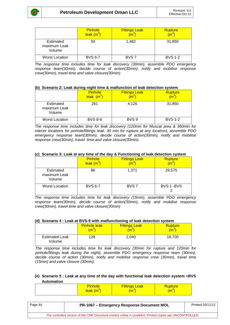
Petroleum Development Oman LLC
Revision: 9.0 Effective:Oct-12
Page 64 PR-1067 – Emergency Response Document MOL Printed 03/11/12
The controlled version of this CMF Document resides online in Livelink®. Printed copies are UNCONTROLLED.
Pinhole leak (m
3)
Fittings Leak (m
3)
Rupture (m
3)
Estimated maximum Leak
Volume
93 1,482 31,850
Worst Location BVS 6-7 BVS 7 BVS 1-2
The response time includes time for leak discovery (30min), assemble PDO emergency response team(30min), decide course of action(30min), notify and mobilise response crew(30min), travel time and valve closure(30min).
(b) Scenario 2: Leak during night time & malfunction of leak detection system
Pinhole leak (m
3)
Fittings Leak (m
3)
Rupture (m
3)
Estimated maximum Leak
Volume
261 4,126 31,850
Worst Location BVS 8-9 BVS 9 BVS 1-2
The response time includes time for leak discovery (120min for Muscat area & 360min for interior locations for pinhole/fittings leak. 30 min for rupture at any location), assemble PDO emergency response team(30min), decide course of action(30min), notify and mobilise response crew(30min), travel time and valve closure(30min).
(c) Scenario 3: Leak at any time of the day & Functioning of leak detection system
Pinhole leak (m
3)
Fittings Leak (m
3)
Rupture (m
3)
Estimated maximum Leak
Volume
86 1,371 29,575
Worst Location BVS 6-7 BVS 7 BVS 1 -BVS 2
The response time includes time for leak discovery (15min), assemble PDO emergency response team(30min), decide course of action(30min), notify and mobilise response crew(30min), travel time and valve closure(30min)
(d) Scenario 4 : Leak at BVS-9 with malfunctioning of leak detection system
Pinhole leak (m
3)
Fittings Leak (m
3)
Rupture (m
3)
Estimated Leak Volume
128 2,040 18,700
The response time includes time for leak discovery (30min for rupture and 120min for pinhole/fittings leak during the night), assemble PDO emergency response team (30min), decide course of action (30min), notify and mobilise response crew (30min), travel time (15min) and valve closure (30min).
(e) Scenario 5 : Leak at any time of the day with functional leak detection system +BVS
Automation
Pinhole leak (m
3)
Fittings Leak (m
3)
Rupture (m
3)
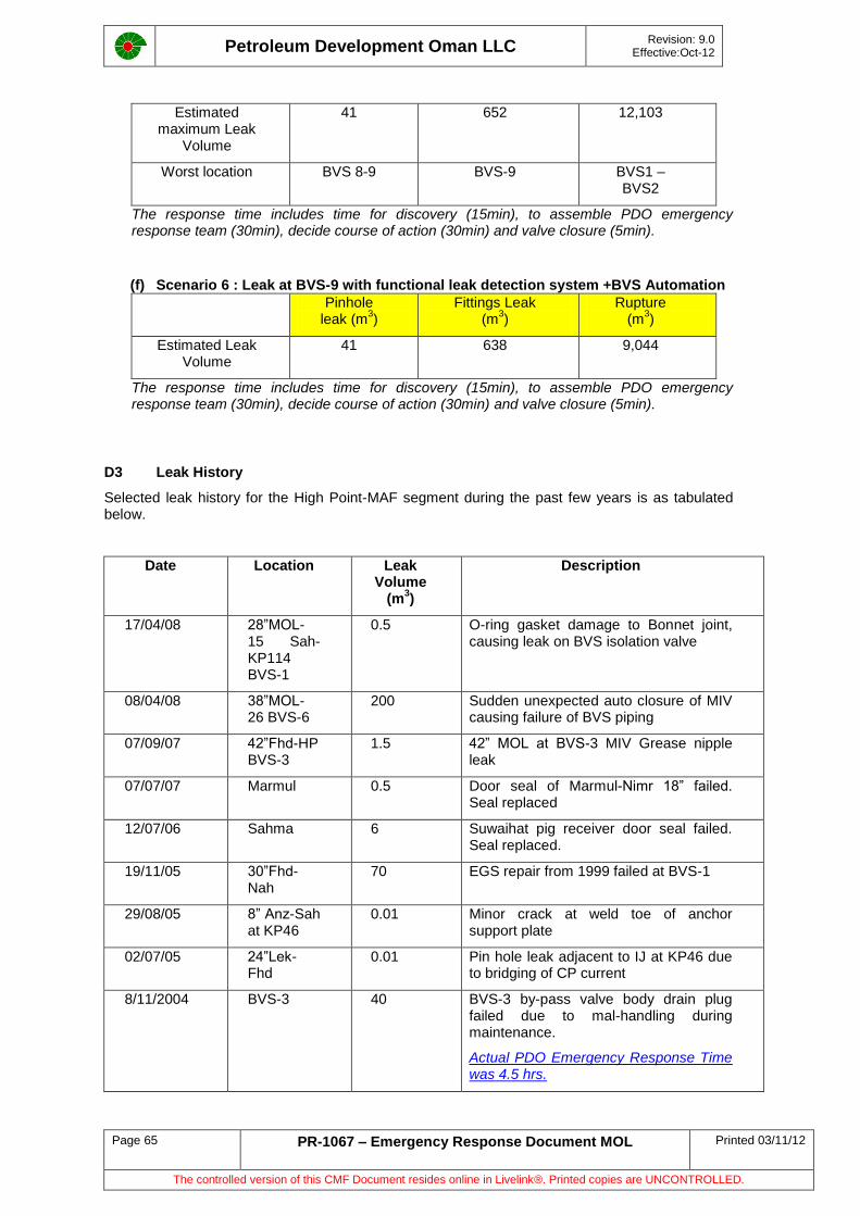
Petroleum Development Oman LLC
Revision: 9.0 Effective:Oct-12
Page 65 PR-1067 – Emergency Response Document MOL Printed 03/11/12
The controlled version of this CMF Document resides online in Livelink®. Printed copies are UNCONTROLLED.
Estimated maximum Leak
Volume
41 652 12,103
Worst location BVS 8-9 BVS-9 BVS1 – BVS2
The response time includes time for discovery (15min), to assemble PDO emergency response team (30min), decide course of action (30min) and valve closure (5min).
(f) Scenario 6 : Leak at BVS-9 with functional leak detection system +BVS Automation
Pinhole leak (m
3)
Fittings Leak (m
3)
Rupture (m
3)
Estimated Leak Volume
41 638 9,044
The response time includes time for discovery (15min), to assemble PDO emergency response team (30min), decide course of action (30min) and valve closure (5min).
D3 Leak History
Selected leak history for the High Point-MAF segment during the past few years is as tabulated below.
Date Location Leak Volume
(m3)
Description
17/04/08 28”MOL-15 Sah-KP114 BVS-1
0.5 O-ring gasket damage to Bonnet joint, causing leak on BVS isolation valve
08/04/08 38”MOL-26 BVS-6
200 Sudden unexpected auto closure of MIV causing failure of BVS piping
07/09/07 42”Fhd-HP BVS-3
1.5 42” MOL at BVS-3 MIV Grease nipple leak
07/07/07 Marmul 0.5 Door seal of Marmul-Nimr 18” failed. Seal replaced
12/07/06 Sahma 6 Suwaihat pig receiver door seal failed. Seal replaced.
19/11/05 30”Fhd-Nah
70 EGS repair from 1999 failed at BVS-1
29/08/05 8” Anz-Sah at KP46
0.01 Minor crack at weld toe of anchor support plate
02/07/05 24”Lek-Fhd
0.01 Pin hole leak adjacent to IJ at KP46 due to bridging of CP current
8/11/2004 BVS-3 40 BVS-3 by-pass valve body drain plug failed due to mal-handling during maintenance.
Actual PDO Emergency Response Time was 4.5 hrs.
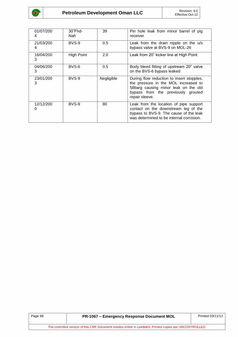
Petroleum Development Oman LLC
Revision: 9.0 Effective:Oct-12
Page 66 PR-1067 – Emergency Response Document MOL Printed 03/11/12
The controlled version of this CMF Document resides online in Livelink®. Printed copies are UNCONTROLLED.
01/07/2004
30”Fhd-Nah
39 Pin hole leak from minor barrel of pig receiver
21/03/2004
BVS-9 0.5 Leak from the drain nipple on the u/s bypass valve at BVS-9 on MOL-26
16/04/2003
High Point 2.0 Leak from 20” kicker line at High Point
04/06/2003
BVS-6 0.5 Body bleed fitting of upstream 20” valve on the BVS-6 bypass leaked
23/01/2003
BVS-9 Negligible During flow reduction to insert stopples, the pressure in the MOL increased to 58barg causing minor leak on the old bypass from the previously grouted repair sleeve.
12/12/2000
BVS-9 80 Leak from the location of pipe support contact on the downstream leg of the bypass to BVS-9. The cause of the leak was determined to be internal corrosion.
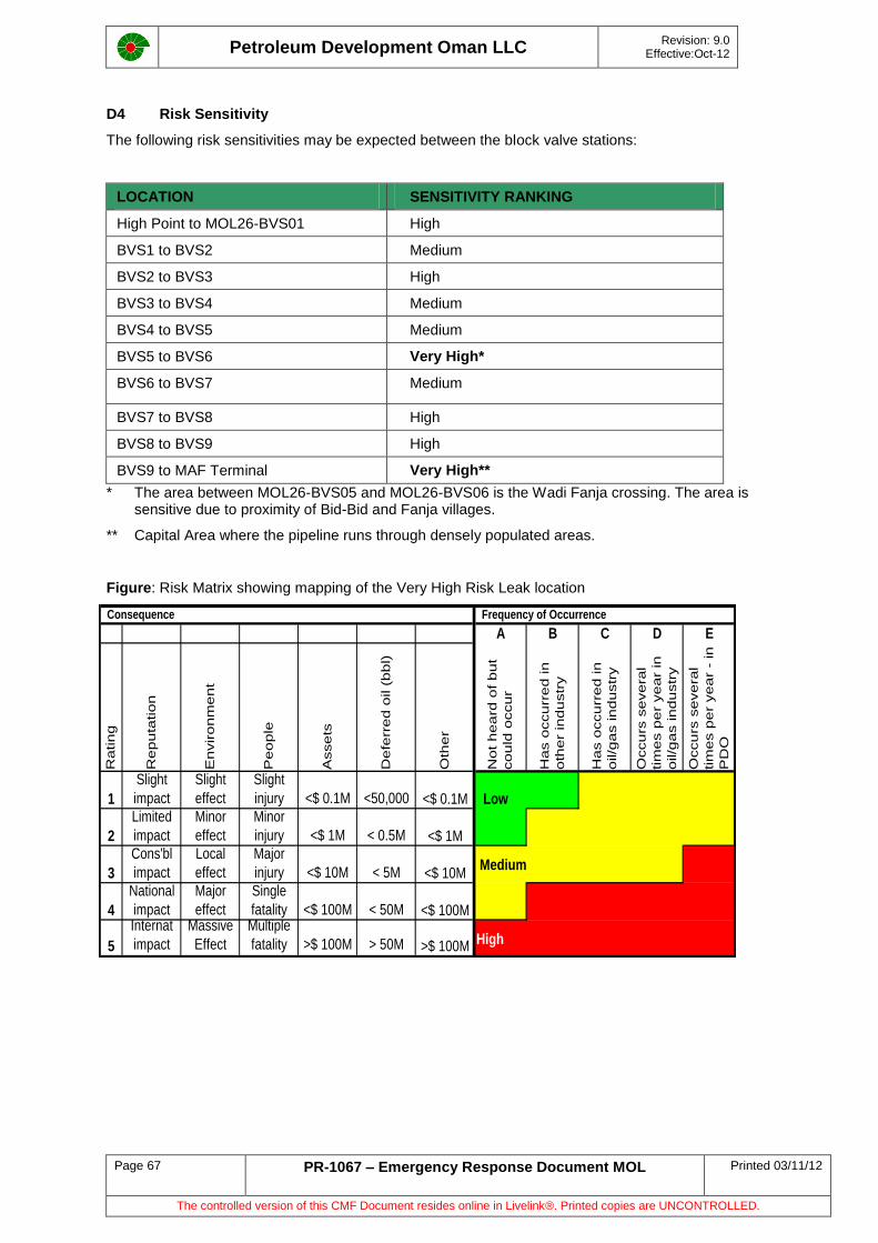
Petroleum Development Oman LLC
Revision: 9.0 Effective:Oct-12
Page 67 PR-1067 – Emergency Response Document MOL Printed 03/11/12
The controlled version of this CMF Document resides online in Livelink®. Printed copies are UNCONTROLLED.
D4 Risk Sensitivity
The following risk sensitivities may be expected between the block valve stations:
LOCATION SENSITIVITY RANKING
High Point to MOL26-BVS01 High
BVS1 to BVS2 Medium
BVS2 to BVS3 High
BVS3 to BVS4 Medium
BVS4 to BVS5 Medium
BVS5 to BVS6 Very High*
BVS6 to BVS7 Medium
BVS7 to BVS8 High
BVS8 to BVS9 High
BVS9 to MAF Terminal Very High**
* The area between MOL26-BVS05 and MOL26-BVS06 is the Wadi Fanja crossing. The area is sensitive due to proximity of Bid-Bid and Fanja villages.
** Capital Area where the pipeline runs through densely populated areas.
Figure: Risk Matrix showing mapping of the Very High Risk Leak location
Consequence Frequency of Occurrence
A B C D E
Rating
Rep
uta
tio
n
En
viro
nm
en
t
Pe
op
le
Asse
ts
Defe
rre
d o
il (
bb
l)
Oth
er
Not
he
ard
of
bu
t
co
uld
occu
r
Has o
ccu
rre
d in
oth
er
ind
ustr
y
Has o
ccu
rre
d in
oil/g
as in
du
str
y
Occu
rs s
eve
ral
tim
es p
er
yea
r in
oil/g
as in
du
str
y
Occu
rs s
eve
ral
tim
es p
er
yea
r -
in
PD
O
1
Slight
impact
Slight
effect
Slight
injury <$ 0.1M <50,000 <$ 0.1M Low
2
Limited
impact
Minor
effect
Minor
injury <$ 1M < 0.5M <$ 1M
3
Cons'bl
impact
Local
effect
Major
injury <$ 10M < 5M <$ 10M Medium
4
National
impact
Major
effect
Single
fatality <$ 100M < 50M <$ 100M
5
Internat
impact
Massive
Effect
Multiple
fatality >$ 100M > 50M >$ 100M High
Petroleum Development Oman LLC
Revision: 9.0 Effective:Oct-12
Page 68 PR-1067 – Emergency Response Document MOL Printed 03/11/12
The controlled version of this CMF Document resides online in Livelink®. Printed copies are UNCONTROLLED.
D5 Risk Mitigation Measures
Measures in Place
Leak detection system in place (June 2008 review to improve functionality started UIT/2,
UPOA/25)
Periodic internal inspection of the pipeline and Fit for Purpose Assessment.
Regular patrolling of the ROW to restrict any encroachments and other activities close to the
pipeline.
Advised Muscat Municipality and other planning agencies to enforce restrictions for future
urban development close to ROW in Muscat Capital Area.
PDO Emergency Response Plan is in place (PR-1067 June 2008)
Pipeline Emergency Repair Manual in place (GU-379 April 2005).
Materials required for emergency pipeline repairs have been procured and stocked in stores
at MAF (Routine check established).
Experienced EMC Contractor in place to attend to emergency situations.
Site Clean up activities are done via Pipeline Maintenance Contractors.
Additional Measures Planned
Implement remote operation of block valves to reduce response time and leak volumes
(project is on-going).
Construct earth bund wall around each block valve station to contain potential leaks.
D6 Conclusions
Although the Main Oil Line is frequently inspected and maintained, potential for loss of containment exist and the segment between High Point and MAF is no exception.
With the worst possible loss of containment scenario, some 32,000 cubic metre of crude oil can be released into the environment. This worst scenario has been calculated to be a pipeline rupture case located approximately between BVS 1 and BVS 2, when the leak detection system is malfunctioning and the leak occurs at night when chances of early detection by passers-by is minimal. With the leak detection system functional and the BVS automation in place, this volume remains high but considerably lower.
From an environmental and PDO reputation standpoint, the worst location for main oil line leak is at Bid-Bid and Capital area where human settlement is high and close to the main oil line. MOL rupture at these locations, especially when the detection system is not functional could result in considerable negative impact on PDO reputation and significant environmental damage.
Rupture of the Main Oil Line is highly unlikely. The more likely pipeline failures due to pinhole and fittings failure are projected to result in considerably lower impact. Nonetheless adequate emergency response plans/procedures are in place to mitigate this risk.
Automating the operation of the Block Valve Stations for remote control facility will further enhance PDO response time to leaks in the High–Point-MAF segment. This project was completed in 2007 but telemetry problems have lead to removing the automation function until further trials have been carried out and the system proven reliable.
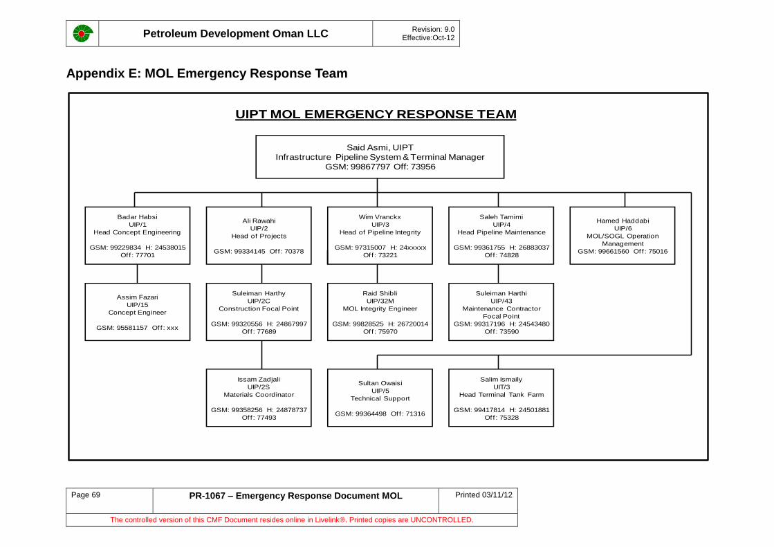
Petroleum Development Oman LLC
Revision: 9.0 Effective:Oct-12
Page 69 PR-1067 – Emergency Response Document MOL Printed 03/11/12
The controlled version of this CMF Document resides online in Livelink®. Printed copies are UNCONTROLLED.
Appendix E: MOL Emergency Response Team
UIPT MOL EMERGENCY RESPONSE TEAM
Said Asmi, UIPT
Infrastructure Pipeline System & Terminal Manager
GSM: 99867797 Off: 73956
Badar Habsi
UIP/1
Head Concept Engineering
GSM: 99229834 H: 24538015
Off : 77701
Raid Shibli
UIP/32M
MOL Integrity Engineer
GSM: 99828525 H: 26720014
Off : 75970
Assim Fazari
UIP/15
Concept Engineer
GSM: 95581157 Off : xxx
Issam Zadjali
UIP/2S
Materials Coordinator
GSM: 99358256 H: 24878737
Off : 77493
Suleiman Harthy
UIP/2C
Construction Focal Point
GSM: 99320556 H: 24867997
Off : 77689
Ali Rawahi
UIP/2
Head of Projects
GSM: 99334145 Of f : 70378
Wim Vranckx
UIP/3
Head of Pipeline Integrity
GSM: 97315007 H: 24xxxxx
Off : 73221
Sultan Owaisi
UIP/5
Technical Support
GSM: 99364498 Off : 71316
Salim Ismaily
UIT/3
Head Terminal Tank Farm
GSM: 99417814 H: 24501881
Off : 75328
Saleh Tamimi
UIP/4
Head Pipeline Maintenance
GSM: 99361755 H: 26883037
Off : 74828
Suleiman Harthi
UIP/43
Maintenance Contractor
Focal Point
GSM: 99317196 H: 24543480
Off : 73590
Hamed Haddabi
UIP/6
MOL/SOGL Operation
Management
GSM: 99661560 Off : 75016
Petroleum Development Oman LLC
Revision: 9.0 Effective:Oct-12
Page 70 PR-1067 – Emergency Response Document MOL Printed 03/11/12
The controlled version of this CMF Document resides online in Livelink®. Printed copies are UNCONTROLLED.
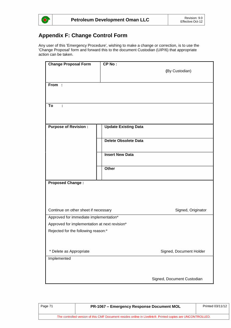
Petroleum Development Oman LLC
Revision: 9.0 Effective:Oct-12
Page 71 PR-1067 – Emergency Response Document MOL Printed 03/11/12
The controlled version of this CMF Document resides online in Livelink®. Printed copies are UNCONTROLLED.
Appendix F: Change Control Form
Any user of this 'Emergency Procedure', wishing to make a change or correction, is to use the 'Change Proposal' form and forward this to the document Custodian (UIP/6) that appropriate action can be taken.
Change Proposal Form
CP No :
(By Custodian)
From :
To :
Purpose of Revision : Update Existing Data
Delete Obsolete Data
Insert New Data
Other
Proposed Change :
Continue on other sheet if necessary Signed, Originator
Approved for immediate implementation*
Approved for implementation at next revision*
Rejected for the following reason:*
* Delete as Appropriate Signed, Document Holder
Implemented
Signed, Document Custodian


![PETROLEUM DEVELOPMENT OMAN (PDO) [Elmech] Development Oman - PDO [Elmec… · Petroleum Development Oman L.L.C. ... Postal Address : P.O.BOX 505- PC 114- SULTANATE OF OMAN Is registered](https://img.pdfslide.us/doc/110x75/5ac633c57f8b9a5c558dcb76/petroleum-development-oman-pdo-elmech-development-oman-pdo-elmecpetroleum.jpg)