Embed Size (px)
Citation preview

PETERHEAD CCS PROJECT FRONT MATTER
Doc. no.: PCCS-05-PT-ZW-7180-00002 Revision: K02 Conceptual Completion & Well Intervention Design Endorsement Report
The information contained on this page is subject to the disclosure on the front page of this document.
i
Peterhead CCS Project Doc Title: Conceptual Completions & Well Intervention Design
Report
Doc No. PCCS-05-PT-ZW-7180-00002 Date of issue: Revision:
12/09/2014 K02
DECC Ref No: 11.093 Knowledge Cat: KKD-Subsurface
KEYWORDS Goldeneye, CO2, Cement, Materials, Completion, Injection, Casing, Corrosion, Gravel Pack, Workover.
Produced by Shell U.K. Limited ECCN: EAR 99 Deminimus
© Shell U.K. Limited 2014. Any recipient of this document is hereby licensed under Shell UK Limited's copyright to use, modify, reproduce, publish, adapt and enhance this document.
IMPORTANT NOTICE
Information provided further to UK CCS Commercialisation Programme (the “Competition”)
The information set out herein (the “Information”) has been prepared by Shell U.K. Limited and its sub-contractors (the “Consortium”) solely for the Department of Energy & Climate Change in connection with the Competition. The Information does not amount to advice on CCS technology or any CCS engineering, commercial, financial, regulatory, legal or other solutions on which any reliance should be placed. Accordingly, no member of the Consortium makes (and the UK Government does not make) any representation, warranty or undertaking, express or implied, as to the accuracy, adequacy or completeness of any of the Information and no reliance may be placed on the Information. Insofar as permitted by law, no member of the Consortium or any company in the same group as any member of the Consortium or their respective officers, employees or agents accepts (and the UK Government does not accept) any responsibility or liability of any kind, whether for negligence or any other reason, for any damage or loss arising from any use of or any reliance placed on the Information or any subsequent communication of the Information. Each person to whom the Information is made available must make their own independent assessment of the Information after making such investigation and taking professional technical, engineering, commercial, regulatory, financial, legal or other advice, as they deem necessary.

PETERHEAD CCS PROJECT FRONT MATTER
Doc. no.: PCCS-05-PT-ZW-7180-00002 Revision: K02 Conceptual Completion & Well Intervention Design Endorsement Report
The information contained on this page is subject to the disclosure on the front page of this document.
ii
Table of Contents Executive Summary 1
1. Introduction 2
1.1. Goldeneye Key Data 2
1.2. Existing Well Specification 2
1.3. Reservoir Characteristics 5
1.4. Fluid Characteristics 6
1.5. Injection Rates and Condition 7
1.6. Pressure and Temperature Condition 8
2. Wells Requirements 11
2.1. Hydraulic Requirements 11
2.2. Well Integrity and HSE 12 2.2.1. Fluids presence in the well 13 2.2.2. Completion material considerations 13
2.3. Well modifications 13 2.3.1. Rig availability 13 2.3.2. Complexity of the initial well modification 14 2.3.3. Special consideration during the initial intervention 14 2.3.4. HSE aspects 14 2.3.5. Facilitate future well abandonment 14
2.4. Operational Aspects 14 2.4.1. Redundant Injection Well 14 2.4.2. Minimum platform intervention 15 2.4.3. Well Intervention 15
2.5. In-well Monitoring Consideration 15 2.5.1. Construction 15 2.5.2. Permanent Downhole Gauges 15 2.5.3. DTS 16 2.5.4. Other in-well equipment 16
2.6. Life Cycle Cost 16
2.7. Regulations & Standards 16 2.7.1. International and Industry Standards 17 2.7.2. Local Laws and Regulations 18
3. Conductor & Casing Review 19
3.1. Summary 19
3.2. Corrosion Survey 20 3.2.1. Results 21 3.2.2. Corrosion Figures 22 3.2.3. Corrosion Report Conclusions 22
3.3. Casing Programme 23

PETERHEAD CCS PROJECT FRONT MATTER
Doc. no.: PCCS-05-PT-ZW-7180-00002 Revision: K02 Conceptual Completion & Well Intervention Design Endorsement Report
The information contained on this page is subject to the disclosure on the front page of this document.
iii
3.3.1. Shell casing design safety factors are: 23 3.3.2. Casing Design Assumptions 23 3.3.3. Conductor 23 3.3.4. Intermediate Casing 24 3.3.5. Production Casing 26 3.3.6. Pre-perforated Liner 29
3.4. Suitability of Casing Design for CO2 Injection 29 3.4.1. Material Compatibility 29 3.4.2. Casing Design for CO2 Injection 30 3.4.3. Low Temperatures 30
4. Cement Review 31
4.1. Summary 31
4.2. Effect of CO2 on Cement and Casing 32 4.2.1. Fluid migration Paths 33 4.2.2. Cement Degradation 34 4.2.3. Cementing / Casing Studies 35 4.2.4. SACROC 37 4.2.5. CO2 Resistant Cements 37
4.3. DIANA Software 38
4.4. Conclusions 40 4.4.1. Other Evidence 41 4.4.2. Shrinkage/Expansion tests 41
5. Lower completion 43
5.1. Summary 43
5.2. Lower Completion Description 43 5.2.1. Formations 44 5.2.2. Lower Completion description with respect of formation tops 44
5.3. Lower Completion under CCS 46 5.3.1. Corrosion in casing 46 5.3.2. Cement degradation 46 5.3.3. Formation and Well Barriers 47
5.4. Lower Completion Strings 49 5.4.1. 7'' Pre-perforated string 49 5.4.2. 4'' Screens string 49
5.5. Gravel Pack / Screens Analysis 50 5.5.1. Material / Corrosion 51 5.5.2. Gravel Pack Design / Operations / Performance 51 5.5.3. Plugging / Erosion 52 5.5.4. Hydrates 55 5.5.5. Injection Experience with Sand Control 55 5.5.6. Flow Reversing (production – injection) 55
5.6. Well Selection Basis 56
6. Goldeneye Well Upper Completions 57

PETERHEAD CCS PROJECT FRONT MATTER
Doc. no.: PCCS-05-PT-ZW-7180-00002 Revision: K02 Conceptual Completion & Well Intervention Design Endorsement Report
The information contained on this page is subject to the disclosure on the front page of this document.
iv
6.1. Current Well Integrity Concerns 57
6.2. CO2 Phase Behaviour 59
6.3. Well Integrity Concerns Due to Extreme Cooling 59
6.4. Tree & Wellhead Concerns 60
6.5. Upper completion Workover 61
7. Upper Completion Concepts 62
7.1. Completion requirements & Options 62 7.1.1. Single Tapered Tubing (Small Tubing) 63 7.1.2. Insert String 64 7.1.3. Dual Completion 66 7.1.4. Concentric Completion 67 7.1.5. Downhole choke 68
7.2. Wellhead & Christmas Tree 69 7.2.1. Dual Completion 69 7.2.2. Concentric completion 69 7.2.3. Single Tapered Tubing 70 7.2.4. Insert String & Downhole choke 70
7.3. Comparison of Completion Concepts - Discussion 70
8. Selected Upper Completion Concept 72
8.1. Packer Fluid requirement 76
8.2. Well Operating Envelope 76 8.2.1. Steady State Operations 77 8.2.2. Transient State Pressure and Temperature Conditions 79
8.3. SSSV testing 80
8.4. Loss of control in CO2 wells 81
8.5. Workover Operation & Complexity 81
8.6. Outline Programme 83
8.7. Intervention Operations 83 8.7.1. Coiled Tubing 84 8.7.2. Wireline 85
9. References 87
10. Appendices 88
APPENDIX 1. Goldeneye Wells 88
APPENDIX 2. WellCat Output Graphs 104
A2.1. Goldeneye Conductor and Surface Casing Assumptions 104
A2.2. Results 104
APPENDIX 3. Casing Design for CO2 Injection 103
A3.1. Casing Design Assumptions 103

PETERHEAD CCS PROJECT FRONT MATTER
Doc. no.: PCCS-05-PT-ZW-7180-00002 Revision: K02 Conceptual Completion & Well Intervention Design Endorsement Report
The information contained on this page is subject to the disclosure on the front page of this document.
v
A3.2. Results 103
A3.3. Surface Casing Loads 104
A3.4. Production Casing Loads 105
A3.5. Minimum Safety Factors - Surface Casing 106
A3.6. Minimum Safety Factors - Production Casing 108
A3.7. Production Temperature Predictions 109
A3.8. CO2 Injection Pressures 110
APPENDIX 4. SACROC Conclusions 110
APPENDIX 5. Cement Testing 113
A5.1. General 113
A5.2. Background 113
A5.3. Goldeneye Platform Conditions 113
A5.4. Cement Testing Outline 113
APPENDIX 6. Original & Conceptual Completion Schematics 115
115
A6.1. Original Completion Diagram 115
A6.2. Dual Completion Concept 116
A6.3. Concentric completion Concept 117
A6.4. Insert String Concept 118
A6.5. Small Bore Completion Concept 119
A6.6. Downhole Choke Concept 120
11. Glossary of terms 121
12. Glossary of Unit Conversions 125

PETERHEAD CCS PROJECT FRONT MATTER
Doc. no.: PCCS-05-PT-ZW-7180-00002 Revision: K02 Conceptual Completion & Well Intervention Design Endorsement Report
The information contained on this page is subject to the disclosure on the front page of this document.
vi
Figures Figure 1-3: GYA01 pressure and temperature traverse profile 10 Figure 1-4: WH and BH pressure and temperature envelope 10 Figure 4-3: Diana Example - GYA04 Risk Analysis of Injection mode for 1000 days 40 Figure 5-2: Aperture velocity in the screen assuming uniform distribution 54 Figure 8-1: Proposed Completion Schematic 75 Figure 8-3: Operating envelope variation with tubing size 78 Figure 8-4: Design Case, Wellhead conditions - 4°C IWHT (2500psi reservoir pressure) 79 Figure 10-6: Goldeneye Casing and Tubing Configuration 105 Figure 10-7: Cumulative 20'' Surface Casing Loads 106 Figure 10-8: 20'' Section von Mises Plot with 12.5 mm Corrosion Loss 107 Figure 10-9: 20'' Safety Factor after 12.5 mm Corrosion 108 Figure 10-10: Goldeneye Tubing – Fluid Pressures 109 Figure 10-11: Goldeneye Tubing – Fluid Pressures 110

PETERHEAD CCS PROJECT FRONT MATTER
Doc. no.: PCCS-05-PT-ZW-7180-00002 Revision: K02 Conceptual Completion & Well Intervention Design Endorsement Report
The information contained on this page is subject to the disclosure on the front page of this document.
vii
Tables Table 1-1: Goldeneye Key Data 2 Table 1-2: Current well specification 2 Table 1-3: Existing hydrocarbon producer wells in Goldeneye platform 3 Table 1-4: Well deviation 4 Table 1-5: Reservoir Characteristics 5 Table 1-6: Fluid Characteristics 6 Table 1-7: Injection rate requirement 7 Table 1-8: Pressure and temperature condition 8 Table 2-1: Results of transient calculations – design case (base oil in annulus) 12 Table 2-2: Industry standards 17 Table 2-3: Local Laws and Regulations 18 Table 3-1: Maximum corrosion rate of Surface Casings and Conductors 21 Table 3-2: Conductor Evaluation 24 Table 3-3: Intermediate Casing Evaluation 25 Table 4-1: Cement Column above 9 ⅝" [245mm] shoe 31 Table 4-2: Injection Parameters 35 Table 4-3: Cement Shrinkage/Expansion Test Results 42 Table 6-1: Well Integrity Overview – eWIMS data 57 Table 6-2: Well Suspension Plugs – Setting Depths (ft) [1ft = 0.3048m] 58 Table 6-3: Tubing to Packer Forces (GYA-02) (1lb=4.45N, 1psi=0.0690bar
,1ft=0.3048m) 59 Table 6-4: Low Temperature Threshold of Current Completion Equipment 60 Table 7-1: Single Tapered Tubing Evaluation 63 Table 7-2: Insert String Evaluation 64 Table 7-3: Dual Completion Evaluation 66 Table 7-4: Concentric Completion Evaluation 67 Table 7-5: Downhole Choke Evaluation 68 Table 7-6: Completion Concept Selection – visualisation 71 Table 8-1: Injection rates vs. tubing size [1''=25.4mm] 77 Table 8-2: Results of transient calculations – design case (base oil in annulus) 80 Table 10-1: Goldeneye wells directional data [1ft = 0.3048m] 88 Table 10-2: GYA01 (14/29a-A3) [1’’ = 25.4mm, 1ft = 0.3048m, 1psi=68.95mbar] 89 Table 10-3: GYA02s1 (14/29a-A4z) 92 Table 10-4: GYA03 (14/29a-A5) 95 Table 10-5: GYA04 (14/29a-A1) 98 Table 10-6: GYA05 (14/29a-A2) 101 Table 12-1: Unit Conversion Table 125

PETERHEAD CCS PROJECT 0.Executive Summary
Doc. no.: PCCS-05-PT-ZW-7180-00002 Revision: K02 Conceptual Completion & Well Intervention Design Endorsement Report
The information contained on this page is subject to the disclosure on the front page of this document.
1
Executive Summary As part of the Peterhead CCS project the Goldeneye platform will undergo a change of use from a hydrocarbons producing field to a CO2 injection field. It is therefore necessary to demonstrate that the Goldeneye wells can perform as desired under the new conditions and retain integrity under prolonged exposure to CO2 during the injection phase and storage lifetime. The purpose of this document is to provide an overview of the injection conditions, an understanding of well requirements and to evaluate the suitability of the components of well construction. It provides assurance that the basis for the selection of the concept for the completions and well intervention design is sound. This document provides an overview of all the components (existing and proposed) that form part of the wells and their capability to perform under the required conditions as laid out in the Well Functional Specification, document no. PCCS-05-PT-ZW-7180-00005, Key Knowledge Deliverable no. 11.098. Areas that have been considered in this report include the conductor and casing, cementation, upper and lower completion, material selection, monitoring requirements and well integrity over the lifecycle. The constructability of the selected concept is reviewed along with plans for future intervention. The well hydraulic requirements and injection conditions impose an operating envelope on the well, this is addressed in the completion concept select and the selected concept allows for adequate flexibility in the injection regime. Analysis of the conductor and surface casing indicates the casing is of sound design for the expected load cases for the duration of the extended field life. An additional survey has been recommended during the define phase to provide up to date inspection data on the casing condition. Exposure of the carbon steel production casing to CO2 is to be limited by selection of suitable annulus fluid and placement of production packer. From field results (SACROC wells), research, software modelling (Diana) and experimental data (shrinkage/expansion tests) it can be concluded that the existing Portland cement is suitable for CO2 injection and storage. It is recommended that the cement quality and placement be evaluated by means such as CBL (cement bong logging) and USIT (UltraSonic Imager Tool). There is no requirement to retrieve or replace the existing 13% Cr lower completion, it is recommended to maintain oxygen levels compatible with the well material. This is to be confirmed in the detailed design phase. In order to mitigate against effects such as plugging and erosion of the lower completion components it is recommended to limit the maximum particle size in the CO2 injection fluid to be as low as 5 microns. The existing upper completion is not suitable for the change of service and requires to be replaced. Various concepts have been evaluated and the Single tapered tubing (small tubing) concept has been selected. The operation involved in replacing the upper completion is standard within the industry. Elements of the proposed completion that require additional engineering have been highlighted to be progressed during the Define phase. It is possible to perform intervention operations with wireline and slickline, the requirement for intervention is reduced by the incorporation of permanent downhole monitoring in the completion design.

PETERHEAD CCS PROJECT 1.Introduction
Doc. no.: PCCS-05-PT-ZW-7180-00002 Revision: K02 Conceptual Completion & Well Intervention Design Endorsement Report
The information contained on this page is subject to the disclosure on the front page of this document.
2
1. Introduction
1.1. Goldeneye Key Data
Table 1-1: Goldeneye Key Data
Attribute Key Data
Name Goldeneye
Area North Sea
Located 100 km northeast of St Fergus
Basin South Halibut Basin of the Outer Moray Firth
Platform Normally Unattended Installation (NUI)
Legs 4
Pipeline to Shore 102 km
Diameter 20'' [508mm]
Reservoir Lower cretaceous Captain sandstone
1.2. Existing Well Specification
Table 1-2: Current well specification
Attribute Specification
Onshore / Offshore Offshore
Well type Hydrocarbon Producer (Suspended)
DFE 152.5ft [46.5m]
Water depth 395ft [120.4m]
Number of wells 5
Top reservoir (TVDSS) 8,300ft [2529.8m]
There are five existing wells in the Goldeneye platform initially drilled and completed to produce hydrocarbons from the Captain sands. The abbreviated well names are used in this document DTI 14/29a-A4Z (GYA02S1) is the sidetrack of DTI 14/29a-A4 (GYA02).

PETERHEAD CCS PROJECT 1.Introduction
Doc. no.: PCCS-05-PT-ZW-7180-00002 Revision: K02 Conceptual Completion & Well Intervention Design Endorsement Report
The information contained on this page is subject to the disclosure on the front page of this document.
3
Table 1-3: Existing hydrocarbon producer wells in Goldeneye platform
Full well name Abbreviated well name Spudded (batch operations)
DTI 14/29a-A3 GYA01 8/12/2003
DTI 14/29a-A4Z GYA02S1 13/12/2003
DTI 14/29a-A4 GYA02 13/12/2003
DTI 14/29a-A5 GYA03 19/12/2003
DTI 14/29a-A1 GYA04 5/12/2003
DTI 14/29a-A2 GYA05 2/12/2003
The field was granted CoP (Cessation of Production) from DECC (Department of Energy and Climate Change) in Q1 2011. There are therefore no plans to produce the wells in the future. These wells can be used as CO2 injectors or monitoring wells. Suspension plugs were installed in the existing production wells after the CoP declaration. Well schematics along with encountered formations are included in Appendix 1

PETERHEAD CCS PROJECT 1.Introduction
Doc. no.: PCCS-05-PT-ZW-7180-00002 Revision: K02 Conceptual Completion & Well Intervention Design Endorsement Report
The information contained on this page is subject to the disclosure on the front page of this document.
4
Below is a simplified schematic of one of the existing wells (GYA01).
Figure 1-1: GYA01 (Existing well completion schematic)
The upper and lower completion specifications of the current completion are: Upper Completion TRSSSV 5.875'', 7'' tubing 6.184'', 5'' tubing 4.67'', PDG 4.576'', PBR 4.577'', Packer 4.65'' Lower Completion FIV 2.94'', Screens 3.548'', X-over 3.515’’ [1''~25.4mm] The maximum well deviation in Goldeneye wells Table 1-4: Well deviation
Well Name Max Hole Angle (degrees)
GYA-01 36
GYA-02S1 60
GYA-03 40
GYA-04 68
GYA-05 7
GYA01AHD TVD
20 x 13 3/8" X-Over 704 70430" Conductor 750 749.75
TRSSSV 2549 2525
10 3/4" x 9 5/8" Casing X-Over 3130 3090
13 3/8" Shoe 4156 4076
7 x 5 1/2" Tubing X-Over 8322 7805
Gauge Mandrel 8383 7859
PBR (Not sheared) 8443 7911
9 5/8" Halliburton Packer 8528 7986
Perforated Pup Joint 8651 8094
9 5/8" Baker Seal Assembly 8681 81219 5/8" Baker Packer 8696 8134
5" Baker Ratcheting Mule 8705 81427" x 5 " X-Over 8744 8176
FIV 8755 8186
5" x 4" X-Over 8785 8212
Liner Hanger 8831 8253
4" Baker screens 89529 5/8" casing shore 9006 8408
7" Predrilled liner
Baker Screens Bull Nose 9154 8539Pre-drilled liner Shoe 9163 8547TD 9166 8550

PETERHEAD CCS PROJECT 1.Introduction
Doc. no.: PCCS-05-PT-ZW-7180-00002 Revision: K02 Conceptual Completion & Well Intervention Design Endorsement Report
The information contained on this page is subject to the disclosure on the front page of this document.
5
GYA03 is currently planned to be a monitoring well during the initial phase of injection. The well will be converted for CO2 injection. Well GYA-02S1 is a sidetrack of the parent hole GYA-02.
1.3. Reservoir Characteristics Table 1-5: Reservoir Characteristics
Attribute Reservoir Characteristics
Type Captain Sandstone
Formation temperature ~83°C @ 8400ft [2560m] TVDss Reduction of temperature around the injectors due to cold CO2 injection (~20 to 35°C bottom hole injection temperature) Reference Case 23°C bottom hole injection temperature
Formation Water Present in the bottom of the well.
Water will be initially at the sand face. Evidence of water from downhole pressure gauges in GYA03.
Formation water around the wellbore will reduce significantly after 6 to 9 months of continuous CO2 injection. However, water might come back to the formation is not enough CO2 is injected in the well.
Average Reservoir (Captain D) Porosity
and Permeability
~25% porosity / 790 mD permeability The Captain D is a clean sandstone with very high Net to Gross
Pressure Regime (The pressure regime is given as an indication for general well/completion design selection. This will be re-calculation before any well operation and before working over the wells). An active aquifer supports the field. All the wells are currently shut in due to water breakthrough and isolated with deep and shallow downhole plugs. Depth: 8400ft TVDss Original Reservoir Pressure ~ 3830psi [264bara] Minimum Reservoir pressure after depletion ~ 2100psi [145bara] Current pressure is ~2620psi [180bara] (December 2013) Minimum expected reservoir pressure before CO2 injection (~Year 2019): 2650psi [183bara]. Pressure Gradient Range (For reservoir pressure of 2650psi - 0.319 psia/ft [0.07216bar/m] Maximum expected reservoir pressure after 10 million tonne of CO2– (~Year 2031) 3450psi [238bar], Pressure Gradient: 0.416psi/ft [0.09410bar/m]. This pressure information will be updated during FEED for the detail design of the wells.

PETERHEAD CCS PROJECT 1.Introduction
Doc. no.: PCCS-05-PT-ZW-7180-00002 Revision: K02 Conceptual Completion & Well Intervention Design Endorsement Report
The information contained on this page is subject to the disclosure on the front page of this document.
6
1.4. Fluid Characteristics Table 1-6: Fluid Characteristics
Attribute Fluid Characteristic
CO2 Almost pure dehydrated CO2 will be available at the platform level
Compound Fraction mol
CO2 0.999883
N2 0.000061
O2 0.000001
H2O 0.000050
H2 0.000005
O2 level specification is determined by the presence of 13Cr (13 percent chrome content metallurgy) material in the wells.
Formation Water Water will be initially at the sand face. Water breakthrough observed in all wells during the production phase. Evidence of water from downhole pressure gauges in GYA03. Salinity- Total Dissolved Solids (TDS): ~56000ppm (52000ppm – Sodium Chloride - NaCl) Water level in the wells is currently not known. It is expected to have more water in the wells at the workover time due to aquifer presence.
Hydrocarbon Gas - Condensate 0.37% mol CO2 0% H2S No solids production observed in the facilities There was a thin (7m) oil rim in the reservoir at original conditions.

PETERHEAD CCS PROJECT 1.Introduction
Doc. no.: PCCS-05-PT-ZW-7180-00002 Revision: K02 Conceptual Completion & Well Intervention Design Endorsement Report
The information contained on this page is subject to the disclosure on the front page of this document.
7
1.5. Injection Rates and Condition Table 1-7: Injection rate requirement
Attribute Injection Rates and Condition
Total CO2 available The project requires to inject 10 million tonnes of CO2 Design Rate (capacity of the capture plant): 138.3 tonnes/h equivalent to 63 MMscfd Normal Operating Conditions ~ 130 tonnes/h (59 MMscfd) Turndown Rate of surface facilities ~ 89.9 tonnes/h (65% of the design case, 41 MMscfd)) It is estimated that the injection will take place over a period of 12 years for the 10 million tonnes including downtime.
CO2 fluctuation For the first 5 years of the injection, project will operate with turndown case of 75% (103.8 tonnes/h, 47 MMscfd)) For the rest of the injection years, the turndown case will be 65%. All the surface equipment should be design to minimum turndown of 65%. The reference case is to operate the capture plant at base load (i.e. continuous flow) during the first five years on injection. Daily fluctuations between the design rate and the minimum (65% of the design rate) might be carried out after year 5 of injection. Frequent (daily) on and off periods of the capture plant are not planned. A limited packing capacity exists in the offshore pipeline operated in dense phase CO2 (estimated to be between 2 to 4 hours of CO2 injection depending on the conditions)
Arrival Pressure and Temperature conditions
The CO2 will be transported to the platform in dense phase. The maximum pressure of the offshore pipeline is 120bar. The CO2 will arrive cold to the platform according to the seabed temperature. Variations exist between summer and winter.

PETERHEAD CCS PROJECT 1.Introduction
Doc. no.: PCCS-05-PT-ZW-7180-00002 Revision: K02 Conceptual Completion & Well Intervention Design Endorsement Report
The information contained on this page is subject to the disclosure on the front page of this document.
8
1.6. Pressure and Temperature Condition The wellhead temperature will range from 0.5°C to 10°C. The CO2 stream arrival temperature to the platform will be between 2.3°C to 10.1°C depending mainly on seabed temperature. The wellhead temperature will also depend on the expansion degree of the CO2 in the surface facilities. The expected arrival temperature to the platform depends mainly on the sea temperature. Metocean data for the Goldeneye field indicates variation in sea temperature between summer and winter. The variation in the P50 seabed temperature is between 6°C and 10 °C. The P50 sea surface temperature has a variation between 7°C and 15 °C The minimum arrival CO2 temperature to the platform in winter is 2.3°C. The temperature drop between the seabed and the CO2 arrival temperature is estimated at 1.7°C for winter conditions and approximately 1°C in summer. The expected manifold conditions in winter is 5.3°C considering an average seabed temperature of 7°C and a temperature drop of 1.7°C at the riser. Table 1-8: Pressure and temperature condition
Wellhead Pressure Minimum: 50 bara Maximum: 115 bara
Temperature conditions Minimum (Winter)
Operational (Winter)
Operational (Summer)
Maximum (Summer)
Goldeneye Site Air temperature, °C
-8.2 24.5
Goldeneye Site Sea surface temperature, °C
1.0 21.0
Goldeneye Sea bed temperature, °C
4.0 7 9 11.0
Arrival CO2 temperature to the platform °C (120bar)
2.3 5.3 8 10.1
Isenthalpic expansion to 115bar, °C
2.2 5.2 7.9 10
Isenthalpic expansion to 50bar, °C
0.5 3.1 5.5 7.2
The current philosophy is to inject CO2 in single phase liquid in the top of the well keeping wellhead pressures above the saturation line to avoid extremely low temperatures in the well caused by the Joule Thomson effect. It is anticipated that the difference between the minimum WH pressure and the CO2 saturation pressure will prevent any potential damage to surface equipment. A minimum margin of 50psia [3.5bar] between the minimum WH injection pressure and the saturation pressure is suggested.

PETERHEAD CCS PROJECT 1.Introduction
Doc. no.: PCCS-05-PT-ZW-7180-00002 Revision: K02 Conceptual Completion & Well Intervention Design Endorsement Report
The information contained on this page is subject to the disclosure on the front page of this document.
9
Figure 1-2: WH pressure requirement
The maximum expected manifold temperature is 10.1 °C. The saturation pressure for this temperature is 45.13bar. The minimum WH pressure for operating the wells is 48.63bar (45.13+3.5). A 50bar minimum pressure has been selected as the minimum WH pressure to operate the wells. The maximum WH pressure is limited by the maximum allowable pipeline pressure. A CO2 arrival pressure to the platform of 120bar [Units] has been highlighted.. Considering pressure drops in the surface equipment (filters, meters, valves, etc.) a maximum available pressure of 115bar at the wellhead has been used. The Figure below shows the pressure and temperature traverse profile (GYA01) for WH pressure of ~50 bara and ~115 bara for reservoir pressure of 2,750 psia [190bar], 3,200 psia [221bar] and 3,800 psia [262bar] for CO2 injection temperature of 4°C. The traverse profile will vary with change in completion type. It is observed from the graph that IBHT (injection bottom hole temperature) ranges from 20°C to 35°C during the injection field life.
-10
0
10
20
30
40
50
0 5 10 15
Pres
sure
, bar
Temperature, degC
WH pressure and Saturation Line
Saturation Line pure CO2 NIST
50bar line
Difference with 45bar

PETERHEAD CCS PROJECT 1.Introduction
Doc. no.: PCCS-05-PT-ZW-7180-00002 Revision: K02 Conceptual Completion & Well Intervention Design Endorsement Report
The information contained on this page is subject to the disclosure on the front page of this document.
10
Figure 1-3: GYA01 pressure and temperature traverse profile
Pressure and temperature prediction for transient condition is critical. The operation procedure should aim to reduce the temperature drop in the wellbore (especially at the top of the well). Below is a graph, which shows the CO2 pressure and temperature conditions during injection in GYA01. The blue lines represent the wellhead and bottom hole pressure and temperature operating envelope. The pink curve represents the injection at 50 bara WH pressure and the green curve is for injection at 115 bara WH pressure.
Figure 1-4: WH and BH pressure and temperature envelope
CO2 Density
0
50
100
150
200
250
300
350
-50 -30 -10 10 30 50 70 90 110
Temperature, degC
Pres
sure
, bar
100 Kg/m3200 Kg/m3300 Kg/m3400 Kg/m3500 Kg/m3600 Kg/m3700 Kg/m3800 Kg/m3900 Kg/m3Saturation1000 kg/m3Curve 1Curve 2
Wellhead Operating Envelope
Bottomhole Operating Envelope

PETERHEAD CCS PROJECT 2.Wells Requirements
Doc. no.: PCCS-05-PT-ZW-7180-00002 Revision: K02 Conceptual Completion & Well Intervention Design Endorsement Report
The information contained on this page is subject to the disclosure on the front page of this document.
11
2. Wells Requirements This section provides an overview of the basic well requirements for the project. Various aspects of well completion are listed which are required to ensure flawless CO2 injection for the well life cycle. These requirements are categorised into six groups namely Hydraulics Requirements, Well Integrity and HSE, Well Modifications, Operational Aspects, In-well monitoring consideration and Life Cycle cost. Hydraulic requirements in the injection wells include management of the CO2 properties (JT expansion) and the resultant temperatures in the existing platform wells, varying injection pressures and injection rate flexibility. Well Integrity and HSE outlines completion material and downhole completion equipment consideration. Well modification includes aspects such as rig availability, complexity of initial well modification, interventions and future well abandonment aspects. Operational aspects cover redundant injection well, minimum platform intervention and in-well interventions requirements. In-well monitoring involves the equipment required to adequately monitor and manage the injector wells and vertical conformance of the CO2. All the above also considers the Life cycle cost of the project. The above-mentioned categorisation provides guidelines which can be used for the selection of Goldeneye well completion philosophy. An integrated approach with all above factors taken into consideration will ensure sustainability of CO2 injection. The above requirements will help to narrow down the completion options. The in-depth design of the selected well completion will align with these well completion requirements.
2.1. Hydraulic Requirements CO2 will be injected in a single phase with wellhead pressures kept above the saturation line. Injecting CO2 can cause extremely low temperatures. The very low temperatures pose severe restrictions in terms of well design including special well materials and equipment and downhole freezing of well annuli. To avoid the low temperatures, the CO2 stream will be kept in single phase by increasing the required injection Wellhead (WH) Pressure above the saturation line. As a result WH temperature will be kept in the design range (above 0°C under steady state conditions) for the wells and operations. The CO2 stream arrival temperature to the platform will range between 3°C to 10°C depending mainly on seabed temperature. Wellhead temperature will range from 0.1°C to 10°C, reference case being 3°C. The required extra pressure drop in the well can be achieved by increasing friction; decreasing the tubing size leads to an increase of the velocity for a particular rate which in turn increases the frictional force in the tubing resulting in an increase of the WH pressure. With an appropriate change in the upper completion the WH Pressure may be increased to the extent that it lies above the saturation line. As such, the minimum WH Pressure in the well is determined by the requirement to operate the well in single phase. When the reservoir pressure increases due to the CO2 injection and aquifer presence, the well hydraulics will change, as even without the aid of pressure (friction or downhole choke), the CO2 will be in single phase across the well.

PETERHEAD CCS PROJECT 2.Wells Requirements
Doc. no.: PCCS-05-PT-ZW-7180-00002 Revision: K02 Conceptual Completion & Well Intervention Design Endorsement Report
The information contained on this page is subject to the disclosure on the front page of this document.
12
By using multiple wells, several different completion sizes should be designed such that they can handle fluctuating injection rates arriving at the platform. To accommodate the wide range in injection rates, tubing size optimization (in the case of CO2 management by friction) is important. Different tubing sizes (from 3 ½” to 4 ½” [88.9mm to 114.3m]) and different length mixes are anticipated for use due to the reasons mentioned above. Consideration will be given to the maximum allowable velocity in the tubing. During transient operations (close-in and start-up operations), a temperature drop is observed at the top of the well for a short period of time. The faster the shut-in or faster the well opening operation, the less the resultant temperature drop. The cooling effect diminishes deeper into the well due to limited CO2 flashing and heat transfer from surrounding wellbore. The reservoir pressure affects the temperature calculation during the transient calculations. The lower the reservoir pressure, the lower is the surface temperature expected during transient operations and hence the higher the stresses/impact in terms of well design. In summary, the expected transient conditions are as follows:
Table 2-1: Results of transient calculations – design case (base oil in annulus)
Design Case Operating case Steady State CO2 manifold T, °C Steady State manifold P, bara Reservoir Pressure, psia
3 120.2
2500 [172.4bar]
- -
2500 [172.4bar] Steady State Conditions WHP, bara WH temperature, °C BH temperature, °C
45 1 17
115 4 20
Transient conditions Close in operation, h Start Up operation, h
2 2
0.5 1
Coldest temperature (wellhead) Fluid CO2, °C Average tubing, °C A annulus, °C Production casing, °C
-20 -15 -11 -10
-17 -10 -4 -1
Strict operational procedures need to be implemented and adopted by the Goldeneye Well Operations Group to avoid extreme cooling of the well components due to temperature limitation of the well components. Frequent opening-up and closing-in events should be avoided to limit the stresses in the well (temperature reduction during short periods of time) and to reduce the operational intensity in the wells. Another activity that could lead to a temperature drop at the top of the well is the SSSV testing. This is explored in further detail in section 8. Selected Upper Completion Concept.
2.2. Well Integrity and HSE Avoiding any leak path through the well is of primary importance. Integration of correct well completion design with operational aspects will ensure that the probability of CO2 leaks through

PETERHEAD CCS PROJECT 2.Wells Requirements
Doc. no.: PCCS-05-PT-ZW-7180-00002 Revision: K02 Conceptual Completion & Well Intervention Design Endorsement Report
The information contained on this page is subject to the disclosure on the front page of this document.
13
wells is minimised as much as possible. To prevent any CO2 leak path, current well investigation with respect to drilling/cementation and completion is necessary. Based on corrosion analysis, well completion design should consider long-term durability of well completion equipment. Seal sections and stagnant zones in the well completion are critical. HSE aspects should be considered during the life cycle of the well (to cover well conversion from hydrocarbon production; to CO2 injection; to final abandonment).
2.2.1. Fluids presence in the well Completion design should consider the presence of CO2 and hydrocarbon (not only CO2). First the injection wells will require well modifications. Hydrocarbons are currently present in the wells. With CO2 injection, the hydrocarbons in the reservoir will be further displaced away from the well. However, it is prudent to assume that the wells might always be in contact with some hydrocarbons. The Captain D is the main Goldeneye reservoir. The Captain E is open in the current lower completion; but the permeability is not as good as the Captain D. Hence the Captain E permeability limits the injection rate of CO2 into the Captain E. In case of an influx in the well, hydrocarbons will be present in the wellbore. The ratio of hydrocarbons to CO2 will decrease with injection time. As such, the wells should always be treated as both hydrocarbon and CO2 wells. The same will apply when well interventions are conducted post CO2 injection start-up.
2.2.2. Completion material considerations All well completion material, including elastomers should be compatible with the injected fluid. Metallic materials like tubing, casing or completion components can suffer serious degradation due to corrosion mechanisms. The different mechanisms may depend on the chosen material in the completion design. Free water plus the CO2 will lead to dissolution of CO2, forming carbonic acid (H2CO3). This leads to corrosion of carbon steel. For 13%Cr this is not considered a corrosion threat. The existing well completion materials are 13%Cr (tubing, liner, screens and accessories) and carbon steel (casing strings). The material selection for the completion should take into account cases in which there is a possibility of presence of free water and oxygen in the feed gas. Material selection study will be performed to prevent any leaks in future through casing. Oxygen level should be controlled to 1ppm max in the phase gas (10ppb dissolved oxygen in the water phase) to prevent corrosion of 13%Cr. A more detailed analysis of the casing and tubing material is included in subsequent sections. There is also a section dedicated to cement and its compatibility with the injected fluid.
2.3. Well modifications
2.3.1. Rig availability In the case that a workover needs to be carried out then a heavy-duty jack up is required due to the 400ft [121.9m] water depth. There are a small number of jackups worldwide that can work in the water depth at Goldeneye location – around a dozen, with some of those on long-term contracts.
PETERHEAD CCS PROJECT 2.Wells Requirements
Doc. no.: PCCS-05-PT-ZW-7180-00002 Revision: K02 Conceptual Completion & Well Intervention Design Endorsement Report
The information contained on this page is subject to the disclosure on the front page of this document.
14
All completion types in terms of installation need to be analysed against Rig and possible alternative Rig-less options. Some completion types, for example dual completions can only be installed by use of a rig. During the FEED phase an effective procurement plan shall be formulated to address such needs.
2.3.2. Complexity of the initial well modification The Peterhead CCS project is a demonstration project, hence a conservative approach might be taken towards the design and selection of the completion, whilst still pursuing new technology. The decision process should also take into consideration the complexity and experience in similar type of offshore environments.
2.3.3. Special consideration during the initial intervention As the reservoir is depleted special measures are essential to ensure there is no impact on the injectivity in the wells and the screens/gravel pack. The completion fluid should be compatible with the well construction in general considering the CO2 aspects (Consider corrosion aspects at the ‘A’ annulus – 9 ⅝” [244.5mm] casing is carbon steel). Long term reliability and effects in the bottomhole temperature should be key factors in this decision. The tubing fluid after workover should facilitate the initial CO2 injection considering the CO2 pressure limitations (~115bar available pressure).
2.3.4. HSE aspects Completion selection should consider HSE aspects during the installation and operation phase. Some completion options have a higher exposure risk due to the complexity of the system. Traditionally the exposure is manageable in the oil industry. The initial workover is considered standard for the oil industry, as the operations will have hydrocarbon conditions only. No workover is planned during CO2 injection, but this cannot be completely ruled out (well integrity, abandonment).
2.3.5. Facilitate future well abandonment The selected completion should facilitate the future abandonment of the wells. The system should lead to a reduction in futures expenses and technical complexities of the final well abandonment.
2.4. Operational Aspects
2.4.1. Redundant Injection Well To cover a varying range of injection conditions and in case of unforeseen problems in a particular injector well, it is proposed to complete an additional well as a CO2 injector to the number of wells required to cover the injection range. Under normal circumstances a redundant well will not be injecting, allowing monitoring of the reservoir in the area (reservoir pressure). It is envisaged that the redundant well will not always be the same well.

PETERHEAD CCS PROJECT 2.Wells Requirements
Doc. no.: PCCS-05-PT-ZW-7180-00002 Revision: K02 Conceptual Completion & Well Intervention Design Endorsement Report
The information contained on this page is subject to the disclosure on the front page of this document.
15
2.4.2. Minimum platform intervention The Goldeneye platform is normally unmanned although it does have some bed space. The selection of the completion option should consider that a minimum presence is to be maintained in the event that manipulation is required in the wells.
2.4.3. Well Intervention The completion should allow for well intervention by means of wireline or coil tubing for surveillance and potential remedial activities. Well intervention is an important aspect to be considered with CO2 injection. The considered completion types will have varying levels of difficulty regarding intervention either for surveillance or for remedial activities. Each completion type will be analysed against well intervention criteria. Wireline and coiled tubing interventions may be limited due to either tubing size or to the way the well is completed. Downhole equipment with very small internal diameter may restrict intervention. These factors need to be considered before completion selection.
2.5. In-well Monitoring Consideration The ability to install in-well monitoring should be considered in the well completion design. Installation of monitoring devices is highly dependent on the type of well completion. As a minimum, the wellhead instrumentation will record pressure and temperature. The requirement for in-well monitoring is:
High Priority: Permanent Downhole Gauges (PDG) Medium Priority: Distributed Temperature System (DTS) Low Priority: Multiple Point Pressure sensor (MPS), Distributed Acoustic system (DAS) and Geophones array.
There is a balance between data collection, well completion operations and costs.
2.5.1. Construction The ability to install in-well monitoring should be considered in the well completion design. The available space to install in-well monitoring will vary with each completion type. The installation complexity of these devices will be dependent on the completion type and size. Factors such as SSSV depth and limited number of wellhead penetrations will play a role in deciding the downhole monitoring equipment.
2.5.2. Permanent Downhole Gauges It is a high priority in the wells to monitor the downhole pressure and temperature. Down Hole Pressure Gauges (DHPG, PDG or PDHG) provide single point pressure measurements in wells. The DHPG will measure both temperature and pressure and are hence often referred to as P/T gauges. The main reasons for installing the PDGS are:
(i) Monitoring and understanding the CO2 behavior in the tubing, (ii) Early identification of injectivity issues (iii) Monitoring of reservoir pressure to be able to calibrate the subsurface models
Additional reasons for their installation include:

PETERHEAD CCS PROJECT 2.Wells Requirements
Doc. no.: PCCS-05-PT-ZW-7180-00002 Revision: K02 Conceptual Completion & Well Intervention Design Endorsement Report
The information contained on this page is subject to the disclosure on the front page of this document.
16
(i) Understanding of the well start-up, (ii) Identification of tubing leaks and (iii) In general it will help to understand any operational issue in the wells.
Due to the variation in density of the CO2 with temperature it is an option to run pressure sensor in series.
2.5.3. DTS It is a medium priority in the wells to monitor the distributed temperature along the well in the injector. Distributed Temperature Sensing (DTS) obtains temperature information through a fibre optic system based on backscattering of laser pulses. Installed in a well, the system measures the temperature continuously along the full length of the fibre optic cable. Changes in temperature that result from changing fluid mixtures or reservoir conditions can be monitored in detail. DTS will require fibre optic capabilities in the wells and on the platform. The main reasons to install the system in the wells are:
(i) Help in the optimisation of the wells start-up, (ii) Tubing leak identification and (iii) Potential identification of out of zone injection.
2.5.4. Other in-well equipment MPS (Multiple Pressure Sensors) can be used to optimise the well hydraulics in the wells. It is possible to combine the DTS with the MPS system using similar cables. It is currently available on the market. DAS (Distributed Acoustic Sensing) is a technology under development that turns a single mode fibre optical cable into a distributed microphone (acoustic sensor). It can use an existing single mode fibre in a DTS control line. Geophones arrays can be installed in the wells to monitor mainly potential out of zone injection and vertical conformance.
2.6. Life Cycle Cost In determining the overall life-cycle cost of the wells, consideration should be given to the initial cost of the installation, the expenses to manage the well during the injection period and the abandonment cost. The life cycle cost is dependent on the number of wells required to be completed for injection, the workover and intervention requirements during the injection phase and the final abandonment costs.
2.7. Regulations & Standards In addition to meeting the requirements prescribed in the sections above, the final well design will conform to the relevant Shell regulations and standards such as technical and process safety requirements as well as industry regulations and standards that have been adopted as part of the global wells delivery process. Some of these standards are listed below. This is not a complete list; however it does highlight a few of the key and most relevant industry standards.

PETERHEAD CCS PROJECT 2.Wells Requirements
Doc. no.: PCCS-05-PT-ZW-7180-00002 Revision: K02 Conceptual Completion & Well Intervention Design Endorsement Report
The information contained on this page is subject to the disclosure on the front page of this document.
17
2.7.1. International and Industry Standards There are industry standards for each well component to be used during the well operations. Those contained in the table below are the most relevant considering the safety aspects in the well.
Table 2-2: Industry standards
Source Name
Wells Oil & Gas UK Guidelines for the suspension and abandonment of wells. Issue 4, July 2012
Wells Oil & Gas UK Guidelines on qualification of materials for the suspension and abandonment of wells
Wells ISO 14310 API 11D1
Packers and Bridge Plugs
Wells ISO 10432 – 10417 API 14A, API 14B
Downhole Safety Valve
Wells ISO 10423 API 6A
Wellhead and Christmas tree equipment

PETERHEAD CCS PROJECT 2.Wells Requirements
Doc. no.: PCCS-05-PT-ZW-7180-00002 Revision: K02 Conceptual Completion & Well Intervention Design Endorsement Report
The information contained on this page is subject to the disclosure on the front page of this document.
18
2.7.2. Local Laws and Regulations
Table 2-3: Local Laws and Regulations
Local Laws and Regulations
Wells Oil & Gas UK, UKOOA
Wells UK Offshore Installations and Wells Regulations - DCR
Storage of CO2 UK Energy Act 2008, CHAPTER 32 STORAGE OF CARBON DIOXIDE, Legal Framework for 2010 No.2221, Chapter 3
Storage of CO2
Monitoring and Corrective Measures
STATUTORY INSTRUMENTS 2010 No. 2221 ENVIRONMENTAL PROTECTION The Storage of Carbon Dioxide (Licensing etc.) Regulations 2010 SCHEDULE 2, 2
Storage of CO2 Monitoring and Corrective Measures
DIRECTIVE 2009/31/EC OF THE EUROPEAN PARLIAMENT AND OF THE COUNCIL of 23 April 2009 on the geological storage of carbon dioxide and amending Council Directive 85/337/EEC, European Parliament and Council Directives 2000/60/EC, 2001/80/EC, 2004/35/EC, 2006/12/EC, 2008/1/EC and Regulation (EC) No 1013/2006 Article 13, ANNEX II, 1.1
Storage of CO2 and Greenhouse gas emissions
DIRECTIVE 2009/29/EC OF THE EUROPEAN PARLIAMENT AND OF THE COUNCIL of 23 April 2009 Amending Directive 2003/87/EC so as to improve and extend the greenhouse gas emission allowance trading scheme of the Community Annex I
Monitoring and Reporting of Greenhouse gas emissions
COMMISSION REGULATION (EU) No 601/2012 of June 2012 on the monitoring and reporting of greenhouse gas emissions pursuant to Directive 2003/87/EC of the European Parliament and of the Council Article 2; Article 20, 3; Annex IV, 23, B.3

PETERHEAD CCS PROJECT 3.Conductor & Casing Review
Doc. no.: PCCS-05-PT-ZW-7180-00002 Revision: K02 Conceptual Completion & Well Intervention Design Endorsement Report
The information contained on this page is subject to the disclosure on the front page of this document.
19
3. Conductor & Casing Review Sections one and two provide an introduction to the Peterhead CCS project and a brief overview of the well requirements. It is now essential to review the components of the well in order to establish their suitability for the project and well integrity. This section looks at the information available on the Goldeneye well conductors and casing strings and analyses this information to confirm the suitability in the injection phase and lifecycle of the well. The Goldeneye platform jacket and topside was installed in 2003 by the Heerema Thialf heavy lift barge. Grade X52 30'' x 1 ½'' [762mm x 38.1mm] wall thickness conductors, complete with Oil States internally upset Merlin connectors, and 2'' [50.8mm] wall thickness drive shoes, were installed and driven to refusal at ~190ft [57.91m] beneath the seabed. Following these operations, Maersk jack-up drilling unit Innovator batch drilled all the wells on Goldeneye Platform. That is all the 17 ½'' [444.5mm] sections were drilled; followed by the 12 ¼'' [311.2mm] sections and finally the 8 ½'' [215.9mm] sections. All the wells consist of a 30” conductor, followed by a tapered surface casing string 20” x 13 ⅜” [508mm x 339.7mm] and a production casing string 10 ¾” x 9⅝” [273.1mm x 244.5]. The wells also incorporate a 7” [177.8mm] pre-perforated 13Cr production liner.
3.1. Summary Goldeneye Platform wells have been analysed with Halliburton WELLCAT software. The analysis models the conditions of CO2 injection.
Due to corrosion reports indicating a potential concern, a special case has been worked up to simulate high 20'' [508mm] corrosion rates. Assuming a high corrosion rate of 0.5 mm/yr and a 25 year life span - both worst cases, it can be concluded that the pipe is still fit for purpose - Safety Factor of 2.4 for axial loading. Furthermore, at high corrosion rate the 20'' casing still has several years' life left beyond the 25 year life span.
Hence Goldeneye 20'' casing will be good for the expected load cases for the duration of the extended field life. It follows that no load transfer to the conductor is expected.
Present Goldeneye platform casing design has been checked for suitability in CO2 injection mode, assuming the expected values for CO2 pressures, temperatures and volumes no issues have been identified with the casing design. Carbon steel compatibility issues with CO2 can be mitigated against provided exposure is kept to a maximum of 165 days of wet events over 15 years.

PETERHEAD CCS PROJECT 3.Conductor & Casing Review
Doc. no.: PCCS-05-PT-ZW-7180-00002 Revision: K02 Conceptual Completion & Well Intervention Design Endorsement Report
The information contained on this page is subject to the disclosure on the front page of this document.
20
3.2. Corrosion Survey The Goldeneye Platform 20'' [508mm] surface casing strings and 30'' [762mm] conductors have been periodically checked for corrosion. Data from these periodic studies carried out during the production phase lead to the concern of high corrosion rates. Coupled with the field life of the platform potentially being extended by another 15 years, this brought into question the load bearing capacity of the 20'' surface casing and possible load transfer to the conductors. The first casing string set inside the conductor was a 20'' x 13 ⅜'' [508mm x 339.7mm] taper string. The 20'' casing has a one inch wall thickness ~25 mm thickness. The 20'' casing was cemented to seabed, but not cemented to surface. That is to say the 30'' and 20'' pipes are freestanding and independent of one another. There are slots cut at 545ft [166.1m] below drill floor, at the bottom of the 30'' allowing the sea to enter and to exit the annulus created between the 30'' conductor and 20'' casing. This annulus between the 30'' and the 20'' is capped by rape seed oil as a mechanism to keep corrosion down. The 30'' conductor and the 20'' surface casing are free standing and independent of one another. That is the 20'' surface casing takes all the well loading and does not transfer the load to the 30'' conductor.
Figure 3-1: Top of Conductor GYA-02 at the South side of the well, showing the 20'' Casing
leaning towards the South-East
As can be seen from the figure, the vertical gap between the two casings is approx. 9'' to 10'' [228.6mm to 254mm]. Also worthy of note is that the surface casing is not centred inside the 30'' conductor. Since the drilling and completion of the Goldeneye wells, the conductors and the surface casing strings have been measured for corrosion by means of a Pulsed Eddy Current (PEC) Tool. Corrosion measurement campaigns have been carried out:

PETERHEAD CCS PROJECT 3.Conductor & Casing Review
Doc. no.: PCCS-05-PT-ZW-7180-00002 Revision: K02 Conceptual Completion & Well Intervention Design Endorsement Report
The information contained on this page is subject to the disclosure on the front page of this document.
21
- Mobilisation 1 1 August 2007 - Mobilisation 2 December 2007 - Mobilisation 3 June 2010
3.2.1. Results Wall thickness results from the latest survey are included in the following table.
Table 3-1: Maximum corrosion rate of Surface Casings and Conductors
Well Spud Date Date of PEC Inspection
Age of Well on Date of Inspection
Maximum Wall Loss
(mm)
Maximum corrosion
rate [mm/yr]
20'' [508mm] Surface Casing
GYA-01 08/12/03 24/05/2010 6.5 2.0 0.31
GYA-02 13/12/03 25/05/2010 6.5 3.6 0.55
GYA-03 19/12/03 24/05/2010 6.4 2.0 0.32
GYA-04 05/10/03 26/05/2010 6.6 1.0 0.15
GYA-05 02/12/03 23/05/2010 6.5 1.8 0.27
30'' [762mm] Conductor
GYA-01 08/12/03 23/05/2010 6.5 3.8 0.59
GYA-02 13/12/03 26/05/2010 6.5 3.8 0.59
GYA-03 19/12/03 24/05/2010 6.4 3.0 0.47
GYA-04 05/10/03 23/05/2010 6.6 3.4 0.52
GYA-05 02/12/03 25/05/2010 6.5 3.4 0.53
Notes: 1. The maximum wall loss in mm was calculated from the maximum wall loss in % and the Nominal
Wall Thickness. The Nominal Wall Thickness is 25.4 mm for all 20'' Casings and 38.1 mm of the 30'' Conductors of the Goldeneye wells.
2. The accuracy in the corrosion rates is estimated to be ±0.39 mm/yr for the 20'' Surface Casing and ±0.59 mm/yr for the 30'' Conductor.
3. The corrosion rate was determined, assuming that the wall thickness was the Nominal Wall Thickness at the spud date.
As can be seen from the table, four out of the five 20'' surface conductors have corrosion rate of 0.32 mm/yr or less. There is only one value greater, of 0.55 mm/yr. All figures have an error of ±0.39 mm/yr.

PETERHEAD CCS PROJECT 3.Conductor & Casing Review
Doc. no.: PCCS-05-PT-ZW-7180-00002 Revision: K02 Conceptual Completion & Well Intervention Design Endorsement Report
The information contained on this page is subject to the disclosure on the front page of this document.
22
3.2.2. Corrosion Figures From the survey report, corrosion has been measured at - range 0.47 to 0.59 mm/year for the 30'' conductor and - range 0.15 to 0.55 mm/year for the 20'' surface casing. It should be understood that these figures are not definitive - only indicative. This is due to differences in pipe height, position that the readings are taken, pipe ovality, steel temperature and other factors including repeatability. Corrosion rates for conductors generally follow a trend. The trend can be low, medium or high corrosion rates. Typical rates are, low 0.1 mm/yr; medium 0.3 mm/yr; and high 0.5 mm/yr and the design duration is usually taken for a 25 year period. Occasionally the corrosion trend figures can reduce; go flat; stay on line or get worse, going towards the high rate. The high rates are the important ones to be aware of. Five years after installation, Goldeneye conductors appeared to be moving into the higher corrosion rate category. As a consequence it was decided to run the conductor and surface casing calculations using worst rates of corrosion of 0.5 mm/yr and a period of 25 yrs. This equates to a surface casing reduction in wall thickness from 25.4 mm to 12.9 mm. This number is derived from original wall thickness of one inch or 25.4 mm and 25 yrs x 0.5 mm/yr.
25.4 - (25 x 0.5) = 12.9 mm potential wall thickness
3.2.3. Corrosion Report Conclusions The 20'' [508mm] Surface Casings and 30'' [762mm] Conductors of wells GYA-01, GYA-02, GYA-03, GYA-04 and GYA-05 were inspected from the top of the Conductor to a few metres below LAT during three campaigns from August 2007 to May 2010. The following conclusions are drawn: 1. The PEC measurements both in 2007 and in 2010 shows that none of the 20'' Surface
Casings and 30'' Conductors of the Goldeneye platform exceeded the 25% wall loss. 25% wall loss is a first-level severity criterion for Surface Casing wall loss of producing wells.
2. The maximum wall loss determined by PEC was 10% or less, on the 20'' Surface Casings and 30'' Conductors of all wells, both in August 2007 and in May 2010, except for the 20'' Casing of GYA-02 in May 2010 (maximum wall loss of 14%) and the 30'' Conductor in August 2007 (maximum wall loss of 12%). The 10% criterion is a reporting criterion for PEC readings. Wall loss less than 10% is regarded as not significant, because 10% variation in PEC reading may be caused by metallurgic variations.
3. The maximum corrosion rate on the 20'' Surface Casing over the period from spud date in 2003 to the PEC measurements in May 2010 ranges from 0.15±0.39 mm/yr (GYA-04) to 0.55±0.39 mm/yr (GYA-02). Only the corrosion on 20'' Surface Casing of GYA-02 is statistically significant.
This finding is consistent with conclusion 2. 4. The maximum corrosion rate on the 30'' Conductor over the period from spud date in 2003
to the PEC measurements in May 2010 ranges from 0.47±0.59 mm/yr (GYA-03) to 0.51 ±0.59 mm/yr (GYA-01 and GYA-02). None of these are statistically significant. This finding is consistent with conclusion 2.

PETERHEAD CCS PROJECT 3.Conductor & Casing Review
Doc. no.: PCCS-05-PT-ZW-7180-00002 Revision: K02 Conceptual Completion & Well Intervention Design Endorsement Report
The information contained on this page is subject to the disclosure on the front page of this document.
23
5. The maximum corrosion rates between spud date and August 2007 and between August 2007 and May 2010 are not statistically significant for any of the 20'' Surface Casings and the 30'' Conductors, except the 20'' Casing of GYA-01 and the 30'' Conductors of GYA-01, GYA-03 and GYA-05 between August 2007 and May 2010. The latter corrosion rates are only just statistically significant. Apart from these exceptions, PEC has therefore not detected statistically significant corrosion.
6. The corrosion rates of both 20'' Casings and 30'' Conductors in the period between August 2007 and May 2010 are not different from the corrosion rate in the period between spud date and August 2007 at the 95% confidence level.
7. The elevation of the maximum corrosion rates on the 20'' Surface Casings is below the fluid level in the 'D' annulus, where no corrosion is expected, except for GYA-03. This is consistent with no significant corrosion on the 20'' Casings.
3.3. Casing Programme
3.3.1. Shell casing design safety factors are:
Burst 1.10
Collapse 1.00
Axial (tension) 1.30
Axial (compression) 1.15
Triaxial 1.10
3.3.2. Casing Design Assumptions Assumptions - Good casing cementation was assumed throughout. - When cementation is across a permeable formation, pore pressure was assumed. - Temperature de-ration was applied to all strings - Buckling effects were taken into account Pressure The target Captain reservoir was taken as normally pressured at 3,852 psia at ~8,300ft [262.6bar at 2530m] TVDSS There were no over pressured or hydrocarbon bearing zones prior to entering the Captain reservoir. Temperature The TD temperature for each well was taken as 181°F at ~8,300ft [82.8°C at 2530m] TVDSS.
3.3.3. Conductor The chosen conductor design for Goldeneye was based on the following criteria. - Conductor to provide marine protection only, no load-bearing requirement.

PETERHEAD CCS PROJECT 3.Conductor & Casing Review
Doc. no.: PCCS-05-PT-ZW-7180-00002 Revision: K02 Conceptual Completion & Well Intervention Design Endorsement Report
The information contained on this page is subject to the disclosure on the front page of this document.
24
- Conductor to be driven - drilling or drill drive not acceptable due to shallow soil stability criteria.
- Fatigue resistance during installation and field life. - Drive ability and resistance to directional deviation. - Merlin mechanical connectors to reduce installation time The final conductor design was generated as a result of collaboration between Heerema (Installation Contractor), UWG (Structural Analysis consultants), Aker (Conductor Fabrication) and Shell Expro. The final design is as follows.
Table 3-2: Conductor Evaluation
Casing
TVD Depth Below Seabed
Minimum S.F. Burst
Minimum S.F. Collapse
Minimum S.F. Triaxial
30'' 1.5'' WT X52 Merlin HDEF connectors
190ft [57.9m]
N/A N/A N/A
3.3.4. Intermediate Casing A reduced casing scheme was adopted based on an extensive offset review and peer challenge sessions. As such, a tapered string of 20'' x 13 ⅜'' [508mm x 340mm] was set as the intermediate string. The tapered string of 20'' x 13 ⅜'' included the 5,000 psia [344.7bar] 18 ¾'' [476mm] Cameron SSMC wellhead system. As such, this string carries the load of the subsequent production casing and completion strings. Analysis of the loads induced (undertaken by UWG) indicated that a string of 13 ⅜'' casing would fail under the buckling load if run inside the 30'' conductor. In consequence, a short section of 20'' casing was run from the 18 ¾'' wellhead to 700ft [213m] TVDBDF. A further finding of the analysis was that due to the bending loads induced by relative jacket and jack up movement, a joint of X80 20'' x 1'' [508mm x 25.4mm] WT is required for the initial 40ft [12.2m] below the wellhead. The section was drilled using an un-weighted pre-hydrated bentonite mud with returns to surface. However, for the event that insufficient shoe strength to facilitate this was achieved at the 30'' shoe, circulation ports were cut in the conductor above the seabed and the 17 ½'' [444mm] section drilled with the bentonite mud system taking returns to the seabed. The 13 ⅜'' shoe was set at 100ft [30.5m] below the top of the Lower Dornoch Mudstone. This was sufficiently deep to enable the 12 ¼'' [311mm] section to be drilled with a planned mud weight of 560 - 580 pptf (maximum mud weight of 620 pptf high inclination wells). An FIT of 630 pptf was expected at the 13 ⅜'' shoe. The string was cemented with returns to seabed, and top up grouting system included to ensure that the TOC was above the 13 ⅜'' x 20'' crossover.

PETERHEAD CCS PROJECT 3.Conductor & Casing Review
Doc. no.: PCCS-05-PT-ZW-7180-00002 Revision: K02 Conceptual Completion & Well Intervention Design Endorsement Report
The information contained on this page is subject to the disclosure on the front page of this document.
25
Table 3-3: Intermediate Casing Evaluation
Casing
Setting Depth Ft MD
Minimum S.F. Burst
Minimum S.F.
Collapse
Minimum S.F. Axial
Minimum S.F.
Triaxial
20'' x 1'' WT, X80, SR20
40 1.13 100 2.33 2.64
20'' x 1'' WT, X65, SR20
700 1.12 12.74 2.70 2.59
13 ⅜'' 68 lb/ft N80, Dino VAM
4,200 1.85 1.24 2.87 2.01
The string design did not allow for total evacuation to gas. The maximum surface pressure in the event of total evacuation to gas is 3,100 psia [214bar]. The maximum working pressure of the 20'' SR20 connector is 2,700 psia [186bar]. As such, the casing was pressure tested with a surface pressure of 2,400 psia [165bar]. However, the expected FIT of 630 pptf allows the circulation of a gas kick in excess of 200 bbls with maximum surface pressure of 2,000 psia [138bar]. BURST (Drilling loads only) External Loads: Fluid Gradients (c/w Pore Pressure): - The 20'' - 13 ⅜'' casing is set across the Tertiary, Beauly and Dornoch, which contain a mix of shales and sands. However, as no issues were recorded during cementing operation on the riser less subsea wells it was assumed that losses were unlikely. As such, the modelling was carried out assuming no discreet permeable zones exist. This coupled with remedial top up cementing programme ensure that the top of cement was at the seabed. The external load was modelled as Fluid Gradients (c/w Pore Pressure). This assumed a column of 520 pptf from the wellhead to seabed and cement from seabed to TD. This figure is high as the cement is setup. Future calculation should allow for this case with a figure in the order of 465 pptf. Internal Loads: Gas Kick: - A swabbed gas kick was modelled in Well Plan 2000 based on various mud weights and 13 ⅜'' shoe strengths. Based on the expected FIT of 630 pptf the maximum kick tolerance is in excess of 300 bbls regardless of mud weight, with a maximum surface pressure of 2,000 psia. Pressure Test: - A 2,400 psia pressure test was applied at surface on top of a 520 pptf column of mud. This is lower than the expected surface pressures in the event of total displacement (see gas kick). Cementing: - Burst during cementation and pressure testing was modelled using a single slurry weight of 650 pptf, with TOC at the seabed and displaced with 520 pptf drilling fluid. A pressure test to 2,400 psia was applied at surface. Drilling fluid at 520 pptf and green cement gradient provide back up throughout the operation. As above, future calculation will need to allow for cement setup.

PETERHEAD CCS PROJECT 3.Conductor & Casing Review
Doc. no.: PCCS-05-PT-ZW-7180-00002 Revision: K02 Conceptual Completion & Well Intervention Design Endorsement Report
The information contained on this page is subject to the disclosure on the front page of this document.
26
COLLAPSE LOADS External Load: Mud and cement-mix water: - The 20'' - 13 ⅜'' casing was set across the Tertiary, Beauly and Dornoch that contain a mix of shales and sands. However, as no issues were recorded during cementing operation on the riserless subsea wells, it was assumed that losses were unlikely. As such, the modelling was carried out assuming no discreet permeable zones exist. This coupled with remedial top up cementing programme ensure that the top of cement will be at the seabed. The external load was modelled as a mud and cement-mix water. This assumes a column of 520 pptf from the wellhead to seabed and cement from seabed to TD. The application of this load case ensured a conservative design. Internal Loads: Cementing: - Maximum differential pressure while displacing the green cement with 520 pptf drilling fluid was calculated as 463 psia [32bar]. Lost returns with mud drop: - The 12 ¼'' [311mm] section was drilled with 560 - 580 pptf mud. However, in the event hole instability issues develop, the mud weight could be increased to a max of 620 pptf. As such, the worst case of a 620 pptf mud was assumed in conjunction with a pore pressure of 3,232 psia [223bar] in the Captain Reservoir the mud drop in the annulus would be 3,319ft [1012m]. Full - Partial Evacuation: - Full evacuation analysis is the worst load case with respect to collapse loads as is indicated by the wear analysis outlined below. AXIAL LOADS
The following loads were applied.
Casing running speed: 1.8ft/sec [0.55m/s]
Max overpull on casing if stuck: 300,000 lbs [1,335kN]
Pre cement static load: 0 klbs
Post cement static loads applied 0 klbs
Green cement pressure test: 2,400 psia
Service loads applied Yes
WEAR TOLERANCE The maximum wear allowance for the 13 ⅜'' casing was modelled to be 7.6% at 4,245ft. This was due to the collapse load case of Full / Partial Evacuation that applies a conservative case of total evacuation without fill up. In reality, it was expected that the casing would be topped up with seawater until equilibrium. The low acceptable wear was as a result of a very conservative load case and as such, it was not considered to be a major risk.
3.3.5. Production Casing The production casing selected is a tapered string of 10 ¾'' x 9 ⅝'' [273mm x 245mm]. The 10 ¾'' [273mm] is required to allow the installation of a 7'' TRSSSV within the completion string. The valve has a minimum setting depth of 2,600ft [793m] TVDSS. This is to ensure it is below

PETERHEAD CCS PROJECT 3.Conductor & Casing Review
Doc. no.: PCCS-05-PT-ZW-7180-00002 Revision: K02 Conceptual Completion & Well Intervention Design Endorsement Report
The information contained on this page is subject to the disclosure on the front page of this document.
27
the hydrocarbon hydrate formation depth for the initial hydrocarbon conditions. The 9 ⅝'' [245mm] shoe was set at the Base Rodby. As such, there is no limitation on the kick tolerance with respect to formation strength. The following table details the production casing design for the Goldeneye wells
Table 3-4: Production Casing Evaluation
Casing
Setting Depth Ft MD
Minimum S.F. Burst
Minimum S.F.
Collapse
Minimum S.F. Axial
Minimum S.F.
Triaxial
10 ¾'', 55.5, L80, VAM Top
2,890 1.41 2.27 1.81 1.44
9 ⅝'', 53.5, L80, VAM Top
8,500- 13,000
1.51 1.29 1.77 1.49
9 ⅝'', 53.5 lb/ft [72.5Nm], L80, VAM Top Alternative drift was used in all wells in order to ensure that the worst case collapse loading is met and to reduce logistical issues during the execution phase. BURST - DRILLING External Load: Pore Pressure / Seawater Gradient: - This load case was selected to ensure that the design is robust to a conservative load case. Internal Loads: Displacement to gas: - A full displacement to dry gas was modelled assuming an influx at TD of the wells. Differential pressures below the wellhead and at the shoe are ~3,000 psia [207bar] and 95 psia [6.55bar] respectively. Pressure Test: - The maximum expected tubing head pressure was calculated to be 3,100 psia [214bar]. Assuming a further 1.1 safety factor, the maximum expected THP could be 3,410 psia [235bar]. The casing design was carried out assuming a surface pressure test of 4,500 psia [310bar] with 0.45 psia/ft [101.8mbar] fluid in hole. Cementing: - Burst during cementation and pressure testing was modelled using 1,000ft lead slurry at a weight of 650 pptf and a 500ft tail cement at 832 pptf displaced with seawater. A pressure test to 4,500 psia was applied at surface. Differential pressure at the shoe is 3,465 psia [239bar]. Drilling fluid (560 pptf) and green cement provide back up for this load. BURST - PRODUCTION: External Load: Pore Pressure / Seawater Gradient: - This load case was selected to ensure that the design is robust to a conservative load case. Tubing leak: - A tubing leak below the wellhead was modelled. Initial reservoir pressures were assumed with a dry gas gradient to wellhead. A maximum pressure at the top of the A annulus
PETERHEAD CCS PROJECT 3.Conductor & Casing Review
Doc. no.: PCCS-05-PT-ZW-7180-00002 Revision: K02 Conceptual Completion & Well Intervention Design Endorsement Report
The information contained on this page is subject to the disclosure on the front page of this document.
28
was calculated at 3,100 psia; this was used for modelling purposes and assumes a dry gas gradient to the wellhead. The packer fluid was modelled at 500 pptf, with the packer positioned 200ft AH above the 9 ⅝'' shoe in each well. Actual packer fluid is inhibited seawater at 450 pptf. COLLAPSE - DRILLING External Load: Mud and Cement Mix-Water: - The external load during drilling was modelled as mud and cement mix water the mud column is assumed as 620 pptf, for all wells which is the worst-case load. This ensures that the most conservative design is applied. Internal Loads: Cementing: - Maximum differential pressure while displacing green cement with seawater is 1,500 psia. Lost returns with mud drop: - The reservoir section was drilled with 540 pptf mud, however the lost returns with mud drop case was run assuming 620 pptf mud in hole with a reservoir pressure of 3,852 psia [266bar]. The drop in the annulus assuming losses would be 2,359ft [719m]. COLLAPSE - PRODUCTION External Load: Mud and Cement Mix-Water: - The external load during drilling was modelled as mud and cement mix water the mud column is assumed as 620 pptf, for all wells which is the worst-case load. This ensured that the most conservative design was applied. Internal Loads: Full Evacuation: - Assumes that the string is vented to atmosphere, i.e. no internal back up. Above and Below Packer: - Assumes that the packer is set 200ft [61m] AH above the 9 ⅝'' casing shoe and the in place packer fluid is 500 pptf. AXIAL LOADS
The following loads were applied.
Casing running speed: 1.8ft/sec [0.55m/s]
Max overpull on casing if stuck: 300,000 lbs [1,335kN]
Pre cement static load: 0 klbs
Post cement static loads applied 0 klbs
Green cement pressure test: 4,500 psia
Service loads applied Yes
Wear Analysis The original analysis showed the maximum predicted wear on the production casing to be up to 10.7% at various depths on all the wells. However, this is not considered an issue as the planned reservoir sections range from 70ft - 200ft in length and as such drilling time is minimal. Note: 10% is the standard default value to allow for casing affected by mechanical abrasion - drilling through casing.

PETERHEAD CCS PROJECT 3.Conductor & Casing Review
Doc. no.: PCCS-05-PT-ZW-7180-00002 Revision: K02 Conceptual Completion & Well Intervention Design Endorsement Report
The information contained on this page is subject to the disclosure on the front page of this document.
29
3.3.6. Pre-perforated Liner Goldeneye Platform wells were lined with pre-perforated 7'' [178mm] liner and hung off with liner hanger and PBR.
3.4. Suitability of Casing Design for CO2 Injection This section of the casing review looks at suitability of existing - casing material compatibility and - casing design for CO2 injection
3.4.1. Material Compatibility All Goldeneye Platform production casing strings are made from carbon steel. The majority of this casing is protected by 13 Chrome material tubing. There are two zones that are exposed to CO2. These are: - below the lower permanent production packer and - a section between the two permanent packers (exposed by a perforated joint) Goldeneye lower completion tubing steel is 13% Cr. This is also the case for the 4'' Screens and 7'' [178mm] Pre-perforated liner. The 9 ⅝'' [245mm] Production Casing is made of Carbon Steel. Free water in combination with CO2 will lead to dissolution of CO2, forming carbonic acid (H2CO3). This might lead to corrosion of carbon steel. For 13% Cr material this is not considered a corrosion threat. The production casing above the existing packer has only been in contact with the completion fluid used in the A-Annulus. That fluid was inhibited seawater installed during the completion operations. Hence the corrosion of this production casing above the packer is expected to be negligible. Condition of the casing below the production packer is less certain due to presence of Goldeneye hydrocarbon gas in contact with the casing. The hydrocarbon gas in Goldeneye has a small content of CO2 (0.4% mol). During the hydrocarbon production phase the 13% Cr components are estimated to have practically no corrosion. Goldeneye gas was in contact with elements below the 9 ⅝'' packer during the production phase. There is a perforated pup joint between the 9 ⅝'' production packer and the screens hanger creating a trapped volume of A-annulus fluid - most likely seawater. Due to the presence of CO2 in the gas there is some corrosion potential in the production casing below the 9 ⅝'' production packer to the casing shoe, especially in the dead volume below the perforated pup joint and the screens hanger. The Goldeneye reservoir is connected to a large aquifer and all five wells are suspended. As such, the lower completion can be in contact with formation water, in addition to the dead volume of water between the 9 ⅝'' production packer and the screen hanger. This is also the case during the transition period between gas production and cessation of gas production to CO2 injection. During the initial phase of CO2 injection the lower completion will be in contact with formation water. Over time, with CO2 injection, the presence of water will decrease as the water is displaced by the CO2, and eventually water presence will disappear. The estimated wet events to avoid corrosion of the 9 ⅝'' production casing below the packer was previously estimated at 3% wet events in 15 years or 165 days of wet events. This represents

PETERHEAD CCS PROJECT 3.Conductor & Casing Review
Doc. no.: PCCS-05-PT-ZW-7180-00002 Revision: K02 Conceptual Completion & Well Intervention Design Endorsement Report
The information contained on this page is subject to the disclosure on the front page of this document.
30
the maximum time allowed to have wet events (CO2 + water). CO2 will be injected dry thereby limiting the wet events. Because of the presence of water in the bottom of the well, the displacing time of the formation water by the CO2 should be considered. Based on CO2 EOR projects it is estimated that the water in the bottom of the well will be displaced in a matter of weeks.
3.4.2. Casing Design for CO2 Injection Casing design has been verified using ''WellCat''TM Halliburton Landmark software. Casing design assumptions and results are included in Appendix 2 and 3. The assumptions take into account the operating parameters - pressures, temperatures and rates that the Goldeneye Platform wells will see during the CO2 injection phase. A 3 ½'' [89mm] tubing string was used in the casing design together with a base oil packer fluid. This tubing size is typical of the tubing size that will be employed during the injection phase. Base oil in the annulus is still subject to ongoing investigation, the alternative being inhibited seawater. The important result is that both the surface casing and the production casing are within limits for the loads modelled with the Shell minimum safety factors.
3.4.3. Low Temperatures
Research (October 2010) on CO2 injection into Goldeneye Platform wells has shown there are cases where low temperatures in the order of -30°C to -40°C may be encountered.
Steady state CO2 injection: These conditions give a temperature and pressure gradient within the bounds of the materials used in Goldeneye Platform well construction and will not cause any problems.
Transient CO2 injection:
There are situations where CO2 injection will stop. - changing injection well - Peterhead CCS project will utilise different tubing sizes to balance
injection rates and backpressure to keep CO2 in supercritical phase - hence injection wells will be matched to delivery
- controlled shut-down / start-up of injection - As well as changing one injection well for another, controlled shut down can occur maybe due to CO2 delivery problems
- emergency shut-down - Goldeneye is a normally unmanned platform. In the event of an emergency shut-down there will be a sudden closing in of one or more wells
During close-in and start-up of a well, there are rapid changes of temperature in the well due to supercritical CO2 flashing of CO2 gas in well bore. The longer it takes to shut down injection, and the quicker the well is started up, the less extreme these temperature fluctuations. The emergency shutdown is the case that must be addressed. By its nature (an emergency) this is a rapid shutdown and it causes the greatest temperature variation / fluctuation. Initial investigation shows these low temperatures to be outside the operating range of some well components. However this is only for the duration of the low temperatures and until the well warms up again - maybe as short as 30 minutes. Hence further investigation is ongoing. The central concern is around the well parts that we do not intend to change out:-

PETERHEAD CCS PROJECT 4.Cement Review
Doc. no.: PCCS-05-PT-ZW-7180-00002 Revision: K02 Conceptual Completion & Well Intervention Design Endorsement Report
The information contained on this page is subject to the disclosure on the front page of this document.
31
- Wellheads - Surface / intermediate casing - Production casing
The results of transient CO2 injection have been incorporated in the Conceptual Well Completion Design Proposal, document no. PCCS-05-PT-ZW-7180-00003. This document also details actions and precautions required to overcome these extreme cooling effects.
4. Cement Review This section provides an understanding of cement degradation modes and mitigation measures. It looks at experience from wells where cement has been exposed to CO2 over a prolonged period of time and results from more recent laboratory-based experiments in order to provide an understanding of the suitability of the cement in the Goldeneye wells to form part of the Peterhead CCS project. An offsite Cement Concept Select workshop was held to discuss the possibilities around cement suitability with regard to CO2 injection. Invitees included various relevant discipline engineers such as well engineers, fluids engineers and technologists. The Concept Select workshop consisted of a presentation and discussion covering: - existing wells and cements - cement degradation mechanisms and leak paths - other CO2 injection examples - software simulation, mechanical model - proprietary CO2 resistant cements Schematics showing the current well construction along with the encountered formations are included in Appendix 1. Goldeneye Wells.
Table 4-1: Cement Column above 9 ⅝" [245mm] shoe
GYA-01 GYA-02s1 GYA-03 GYA-04 GYA-05 Theoretical Top of Cement 7506 9768 7865 11510 6895 Production Packer Setting Depth 8528 10675 8894 12517 7941 9-⅝" Casing Shoe 9006 10990 9365 13010 8395 Cement column above shoe 1500 1222 1500 1500 1500
4.1. Summary The effect of CO2 injection on the cement in Goldeneye wells is discussed in this document. The Goldeneye wells have been cemented with Portland class G cement which has been reviewed for suitability for injection of CO2, with the conclusion that all wells will be fit for CO2 injection. Diana software, a specialist mechanical cement model has been run to ascertain the effects of CO2 injection on Goldeneye Platform. The results indicate that there will be no mechanical problems due to CO2 injection.

PETERHEAD CCS PROJECT 4.Cement Review
Doc. no.: PCCS-05-PT-ZW-7180-00002 Revision: K02 Conceptual Completion & Well Intervention Design Endorsement Report
The information contained on this page is subject to the disclosure on the front page of this document.
32
Chemically, due to the absence of water in the delivered CO2 - injection phase - once water, and hydrocarbons have been displaced - there is no mechanism to create corrosive carbonic acid. Later in the life of the wells, after the injection phase, reservoir dynamics such as gravity, miscibility and reactions with downhole formations, will mean carbonic acid will reappear at the base of the cement in the Goldeneye wells. As above, this is not expected to be a problem for Goldeneye wells. Cement test results show negligible expansion and contraction of samples made from a mix similar to that used in the Goldeneye wells. After cessation of CO2 injection, Goldeneye wells and the Goldeneye platform will be abandoned. The choice of cements for abandonment and the style of abandonment will be decided by cementing technology, industry best practices and legislation in place at the time. Specialist cements could be qualified to see if they are significantly better than Portland cement. If so, a new drill well or a side-track from existing well may be cemented with a CO2 resistant cement in any portion of the well where the cement would be in contact with CO2. As workovers on the Goldeneye Platform will not occur until later it is recommended that qualification of CO2 resistant cement be followed up after the FEED Contract has been awarded and nearer to the start-up date. This would give greatest benefit to emerging research in this new area.
4.2. Effect of CO2 on Cement and Casing There is a wealth of published material on the effects of CO2 injection on oilfield cement and tubulars. The degradation mechanisms are outlined below, followed by outlines of some of the more recent and high profile papers plus their conclusions.

PETERHEAD CCS PROJECT 4.Cement Review
Doc. no.: PCCS-05-PT-ZW-7180-00002 Revision: K02 Conceptual Completion & Well Intervention Design Endorsement Report
The information contained on this page is subject to the disclosure on the front page of this document.
33
4.2.1. Fluid migration Paths Possible migration pathways through a well: (a) between casing and cement; (b) between cement plug and casing; (c) through the cement pore space as a result of cement degradation; (d) through casing as a result of corrosion; (e) through fractures in cement; and (f) between cement and rock. From Gasda et al. (2004). Ref. below
Figure 4-1: Fluid Migration Paths
Gasda, S., J.M. Nordbotten, and M.A. Celia, "Upslope Plume Migration and Implications for Geological CO2 Storage in Deep Saline Aquifers", IES Journal of Civil Engineering, Vol. 1, No. 1, page 1, 2008. These leak paths would occur and develop due to potential cementing defects such as: - Inadequate placement of cement resulting in channels or mud films, - Channels caused by gas migration during cement hydration, - Cracks caused by cement failure in compression/traction, and - Micro annuli caused by lack of bonding at the interfaces with casing and/or rock, or due to
poor P/T techniques

PETERHEAD CCS PROJECT 4.Cement Review
Doc. no.: PCCS-05-PT-ZW-7180-00002 Revision: K02 Conceptual Completion & Well Intervention Design Endorsement Report
The information contained on this page is subject to the disclosure on the front page of this document.
34
4.2.2. Cement Degradation Cement degradation occurs in three phases. That is to say, the interaction between Portland cement and CO2 is a 3-step process: - Carbonic acid diffusion, - Cement (Portlandite) dissolution and carbonate precipitation, and decrease in porosity - Leaching (calcium carbonate dissolution). Cement sheath defects would cause acceleration
of the degradation process, generally leading to loss of density and strength and an increase in porosity.
This process relies on the presence of water. That is, water is required to form carbonic acid completing the first phase allowing the following two processes to occur. Goldeneye CO2 delivery is expected to be more or less free of water. However, water may be present around the wellbore. The other main factors in cement degradation are temperature, pressure, and time. Elevated temperatures and elevated pressures both speed up the degradation process. The delivery temperature of CO2 into Goldeneye is expected to be around that of the sea at approx. 40°F [5°C], due to delivery via subsea pipeline. Initial injection pressure will be ~2,500 psia [172bara] and rise higher as injection proceeds - towards 3,700 psia [255bara]. Downhole temperature at the reservoir level will be in the order of 20°C during CO2 injection. When injection has ceased, in the long term, the downhole temperature will return to the initial reservoir temperature of 83°C. Due to the degradation mechanism, cement degradation from studies has been found to be time dependant. The equation can be simplified as a constant multiplied by the square root of time. Goldeneye is expected to inject dry CO2 - that is without water. During the injection phase, if water and subsequently carbonic acid does get to the casing cement sheath, a product of carbonic acid reacting with cement is an insoluble precipitate - calcium carbonate (CaCO3). It leads to lower porosity in the cement because calcium carbonate has a higher molar volume than Ca(OH)2 and for cement sheath integrity, this reaction actually improves the cement’s properties and the carbonation is therefore a self-healing mechanism in the carbonate. Rate of cement degradation depends on three factors - heat, pressure, and the square root of time. Goldeneye wells will be supplied with CO2 at low temperature 0 to 5°C at the wellhead in a supercritical state through a subsea pipeline. Injection wells in the United States are generally fed with CO2 at ambient temperature. Hence, lower Goldeneye temperatures are working towards smaller rates of degradation than comparable American wells.
4.2.2.1. Steps To Avoid Cement Degradation
There are a number of basic steps that can be taken to minimise degradation of cement by CO2:
- pump dry CO2; no water in the injected CO2 means no carbonic acid. - cement placement; good spacer, lead and tail and good centralisation to avoid voids in the
cement. In addition, for abandonment plugs, balanced cement plugs to avoid stringers and channelling.

PETERHEAD CCS PROJECT 4.Cement Review
Doc. no.: PCCS-05-PT-ZW-7180-00002 Revision: K02 Conceptual Completion & Well Intervention Design Endorsement Report
The information contained on this page is subject to the disclosure on the front page of this document.
35
- keep excess water to a minimum; have as little unreacted water as possible in cement slurry. Without water, CO2 cannot form carbonic acid. Use a suitable filler, inert to CO2, to close up the interstitial spaces.
- best cementing practices; all the standard requirements such as slurry testing, fresh cement, good additive control, mixing at constant density, no hold ups whilst pumping the job etc.
- avoid water based fluids in workovers; once CO2 injection has commenced, if possible, avoid water based fluids in workovers. This is to minimise the combination with CO2 in the well to produce carbonic acid
The reaction of Portland cement with carbonic acid forms a CaCO3 film or layer on the cement surface. This slows and can stop the reaction process. Any free water in the cement can allow the formation of more carbonic acid and continue the reaction process. Expansion and contraction can also cause micro-fractures in the cement or chip tiny bits off. If there is any free water, it will be exposed or the water released. The process of carbonic acid formation and cement attack then starts again.
4.2.3. Cementing / Casing Studies
Table 4-2: Injection Parameters
Since about 2005, there have been a number of high profile studies into the effects of CO2 on Portland cements. Below is a summary of a few of the major studies that are frequently reported. The effect of CO2 alterations on Portland cement containing calcium silicate hydrates and calcium hydroxide was studied in both laboratory experiments and field tests. Regular Portland-based cements contain Ca(OH)2, which reacts with CO2 when water is present to form solid calcium carbonate through the following chemical reaction: Ca(OH)2 + CO3
2- + 2H+ = CaCO3 + 2H2O This process is named cement carbonation. Even if this process alters the composition of the cement, it leads to lower porosity in the cement because calcium carbonate has a higher molar volume (36.9 cm3) than Ca(OH)2 (33.6 cm3) (Shen and Pye, 1989). For cement sheath integrity, this reaction actually improves the cement’s properties and the carbonation is therefore a self-healing mechanism in the carbonate.
Attribute Value
Surface CO2 delivery temperature: 5°C
Downhole reservoir temperature: 83°C
CO2 state: Supercritical
Downhole pressure (2010): 2,100 psia [145bara]
Eventual Pressure (post injection): 3,700 psia [255bara]
Cement: Class G
Temperature at reservoir during injection expected
~+20 to +30°C

PETERHEAD CCS PROJECT 4.Cement Review
Doc. no.: PCCS-05-PT-ZW-7180-00002 Revision: K02 Conceptual Completion & Well Intervention Design Endorsement Report
The information contained on this page is subject to the disclosure on the front page of this document.
36
In a CO2 sequestration project, the supply of CO2 around the wellbore will continue the carbonation process as long as Ca(OH)2 is present in the cement. The calcium carbonate is also soluble with the CO2, even though it is more stable than Ca(OH)2. Experiments by Kutchko et al (2007) showed that when all Ca(OH)2 has reacted in the carbonation process, the pH will drop significantly (Zone 1 in Figure 4.2). When the pH drops, more of the CO2 will react with water and form HCO3- (Zone 2 in Figure 4-2). The abundance of HCO3- will react with the calcium carbonate to form calcium (II) carbonate, which is soluble in water and can move out of the cement matrix through diffusion (Kutchko et al, 2007). The final reaction that occurs in Zone 3 (close to the cement surface) is calcium silicate hydrate reacting with H2CO3 to form calcium carbonate (CaCO3) according to the following chemical reaction: 3 H2CO3 + Ca3Si2O7 * 4H2O = 3 CaCO3 + 2 SiO2 * H2O + 3 H2O The volume of calcium silicate hydrate is larger than the calcium carbonate and this reaction will increase the porosity of the cement in Zone 3, which is the closest to the reservoir formation containing the CO2.
Figure 4-2: Degradation of Wellbore Cement by Saturated Brine Exposure
Illustration of the different Zones due to the chemical reactions occurring in the cement core during testing. Zone 1 Ca(OH)2 dissolves and CaCO3 forms. Zone 2 CaCO3 dissolves when Ca(OH)2 is spent. Kutchko et al. (2007). Barlet-Gouedard et al (2006) tested a Portland cement API Class G in both saturated water and supercritical CO2 at 90°C. The rate that carbonation occurred for wet supercritical CO2 conditions was measured and the rate of the alteration front was calculated based on: Depth of CO2 alteration front (mm) = 0.26 (time in hours)1/2 From graphical extrapolation in the Barlet-Gouedard example, the carbonation process will have penetrated 10 mm into the sample after 60 days or 100 mm after 17 years. Kutchko et al (2008) performed similar experiments on a Class H Portland cement slurry at 50°C with a CO2 saturated brine (Figure 5 and 6). The results for CO2 supercritical brine at 50°C showed a slower alteration front within the cement. The curve fit estimating alteration depth based on Kutchko et al (2008) results for supercritical CO2, comes out as:
PETERHEAD CCS PROJECT 4.Cement Review
Doc. no.: PCCS-05-PT-ZW-7180-00002 Revision: K02 Conceptual Completion & Well Intervention Design Endorsement Report
The information contained on this page is subject to the disclosure on the front page of this document.
37
Depth of CO2 alteration front (mm) = 0.016 (time in days)1/2 Barlet-Gouedard et al (2008) summarized their CO2 durability experiments for different cement mixtures. The results indicate that only the Schlumberger proprietary EverCreteTM is stable towards long-term CO2 attack. The ThermalockTM from Halliburton was not part of the study.
4.2.4. SACROC SACROC is an interesting and relevant insight into the effects of CO2 on oilfield cements and tubulars. A 52 year old SACROC well with conventional, Portland-based well cement, was exposed to CO2 flooding operation for 30 years at the SACROC Unit, located in West Texas. At the end of its life, the well 49-6 was cored bringing to the surface samples of cement and casing. The well was being investigated as part of a programme to evaluate the integrity of Portland-cement based wellbore systems in CO2 - sequestration environments. The recovered cement had air permeability in the tenth of a milliDarcy range and thus retained its capacity to prevent significant flow of CO2. There was evidence, however, for CO2 migration along both the casing - cement and cement - shale interfaces. A 0.1 - 0.3 cm thick carbonate precipitate occurred adjacent to the casing. The CO2 producing this deposit may have travelled up the casing wall or may have infiltrated through the casing threads or points of corrosion. The cement in contact with the shale (0.1 - 1 cm thick) was heavily carbonated to an assemblage of calcite, aragonite, vaterite, and amorphous alumino-silica residue and was transformed to a distinctive orange colour. The CO2 causing this reaction originated by migration along the cement - shale interface where the presence of shale fragments (filter cake) may have provided a fluid pathway. The integrity of the casing - cement and cement - shale interfaces appears to be the most important issue in the performance of wellbore systems in a CO2 sequestration reservoir. The most basic observation of the SACROC core is that at well 49-6, Portland cement survived and retained its structural integrity after 30 years in a CO2 - reservoir environment. While the cement permeability is greater than typical pristine Portland cement, it would still provide protection against significant movement of CO2 through the cement matrix. The location of the sample at only 3 - 4 m above the reservoir contact suggests that the majority of the cement forming the wellbore seal has survived and would provide a barrier to fluid migration. The cement bond log supports this interpretation of the persistence of cement throughout the near CO2 -reservoir environment. The conclusions of the investigation are provided in Appendix 4. SACROC Conclusions. The SACROC well was first put on line over 50 years ago. Recovery of sections of SACROC well showed that ordinary Portland cement could be successfully used to produce hydrocarbons and then inject CO2 for 30 years. With the improvements in cement formulations; placement techniques and volume of cement in North Sea wells, the resulting degradation resistance to CO2 should be better than SACROC.
4.2.5. CO2 Resistant Cements CO2 resistant cements have been introduced by cementing companies in response to the growth of CO2 injection projects. These speciality cements first came to prominence around 2005. All three main suppliers to the oil industry have provided and used these specialist cements around the world in CO2 environments. Products are: - Schlumberger Well Services EverCRETE

PETERHEAD CCS PROJECT 4.Cement Review
Doc. no.: PCCS-05-PT-ZW-7180-00002 Revision: K02 Conceptual Completion & Well Intervention Design Endorsement Report
The information contained on this page is subject to the disclosure on the front page of this document.
38
- Halliburton ThermaLock Cement - BJ Services PermaSet cement Calcium Aluminate Cements, known as Fondu Cement are also available from companies such as Lafarge. Cement Fondu is cement based on calcium aluminates - between 40% to 50% of the composition, rather than calcium silicates, which are the basis of Portland cement. Unlike Portland cement, Fondu does not release free lime during hydration. This gives them low porosities that have an excellent resistance to chemical attack, from a wide range of aggressive substances such as CO2. Fondu cements are however incompatible with Portland cements, as Fondu is an accelerator for Portland. The cement company literature shows CO2 resistant cements as better adapted to degradation than Portland cements. It is possible that these comparisons are slanted to show the vendors' product in a better light - for example by having excess free water in the Portland mix. However, independent checking or cement qualification is the only way to conclusively verify this. As CO2 resistant cements are inert, or close to inert, to CO2, any research or qualification of these cements would need to concentrate on mechanical integrity. That is the bonding to formations, to metals, plus triaxial properties. Other factors that must be understood are: - difficulty of predicting cement setup times - incompatibility with Portland cements - isolation of mixing system or cleanliness of mixing system - mixing and issues around placement must be resolved - age testing of these cements - how to satisfactorily simulate 1,000 years
4.3. DIANA Software TNO DIANA BV in the Netherlands is a specialist software company that has developed a mechanical cement model. This has been used to simulate the downhole conditions and effects on cement in Goldeneye Platform wells. Diana Software is strictly a mechanical model. That is it takes no account of chemical effects on cement by carbonic acid. The injection model simulates the thermal effects on the mechanics of the system (casing/formation/cement). Diana software is fairly flexible. It can model a shut-in and 'turn the well around' to flow it or to switch to injecting something else such as water. It cannot simulate repeated cycles of start/stop simulations. Diana software was run to simulate the mechanical effects on production casing cement of Goldeneye Platform wells. It was used to look at the cement-formation, cement-steel bond in Goldeneye platform wells. The Diana software programme has many inputs and where possible, actual Goldeneye values were used. Values not available such as cap rock shale properties and vertical stress gradients have had typical values applied from local data around the Goldeneye area. Diana results indicate that the remaining integrity of the cement is sufficient for CO2 injection into the Goldeneye Platform wells. Reworking of input values to give better indication of expected well temperatures and actual centralisation stand-off was carried out in late 2010. These results similarly proved positive - the remaining capacity of the cement sheath for various simulated operational scenarios is sufficient for CO2 injection into the Goldeneye Platform wells.

PETERHEAD CCS PROJECT 4.Cement Review
Doc. no.: PCCS-05-PT-ZW-7180-00002 Revision: K02 Conceptual Completion & Well Intervention Design Endorsement Report
The information contained on this page is subject to the disclosure on the front page of this document.
39
Inputs for the injection modelling include temperatures and pressures predicted from OLGA SPT software and WELLCAT software. Inputs into the model include; - cement formulation - placement - centralisation - cement tops - cement bond logs - temperatures - pressures - casing testing - thermal cycling - vertical stress gradient - max and min horizontal stress ratio - azimuth of max horizontal stress - Young's modulus - Poisson's ratio - cohesion - friction angle - in-situ stresses - lithology types - volumetric specific heat - thermal conductivity, and thermal expansion - hardening type (linear hardening or softening, or parabolic softening) and corresponding hardening gradient and fracture energy The programme results indicate that the existing cement is not compromised and is good for CO2 injection. The risk of damage over load phases have been calculated for various scenarios - curing - pressure testing - completion - shut-in - injection Three cases have been modelled. These are: - Risk of analysis of production mode for 5 years - Risk analysis of injection mode for 1,000 days - Risk analysis of injection mode for 1,000 days, maximum cool down but no reservoir or
casing pressure increase. These cases are evaluated against the following - de-bonding at formation - debonding at casing - shear deterioration in cement - radial cracks in cement

PETERHEAD CCS PROJECT 4.Cement Review
Doc. no.: PCCS-05-PT-ZW-7180-00002 Revision: K02 Conceptual Completion & Well Intervention Design Endorsement Report
The information contained on this page is subject to the disclosure on the front page of this document.
40
Figure 4-3: Diana Example - GYA04 Risk Analysis of Injection mode for 1000 days
In all cases and all instances, the results show the ''remaining capacity'' of the cement is good. The remaining capacity is a measure of the cycling or fatigue that is left in the cement system. The lowest remaining capacity case is down to 40 percent. This lowest case is, 'Risk analysis of injection mode for 1,000 days, maximum cool down but no reservoir or casing pressure increase' and 'de-bonding at formation'. The programme has been rerun 4Q2010 with updated input values and for CO2 injection. The programme still gives acceptable values for remaining capacity. These are within five percent of the 2009 values and within the repeatability of results.
4.4. Conclusions All the summary indications are that existing Portland cement is acceptable for CO2 injection into Goldeneye wells. Cement placement has been reviewed for all the wells. Cement composition and volumes placed are all consistent with good practices. In the Goldeneye case, the injected super-critical CO2 will be dry. Hence during dry CO2 injection, carbonic acid is not formed and hence removes the potential for chemical reaction with Portland cement. This takes away the main cause of degradation of the cement. However later in the wells' life there are cases where water shall be present around the wellbores so carbonic acid degradation cannot be discounted.

PETERHEAD CCS PROJECT 4.Cement Review
Doc. no.: PCCS-05-PT-ZW-7180-00002 Revision: K02 Conceptual Completion & Well Intervention Design Endorsement Report
The information contained on this page is subject to the disclosure on the front page of this document.
41
Field results such as the SACROC CO2 injection well indicate that Portland cement can retain its integrity in a hostile CO2 environment. Software modelling indicates the remaining capacity of the existing cement is good. The conclusion is that existing wells are suitable. Portland cements can be modified to slow or prevent reaction with CO2. Specialist non Portland CO2 resistant cements may have erratic setting times and are difficult to mix and to place downhole. If it is decided to use these cements, independent stress modelling and testing will be required. There are other technologies that should be investigated such as swelling technologies, alternative plugging materials, and self-healing cements. Prior to commencing CO2 injection CBL (Cement Bond Logging) and USIT logs will be performed to evaluate the cement quality, presence and placement. The CBL provides and overall idea of the cement to formation and casing to cement bond. Analysis of the echo from a USIT provides an indication of rugosity, casing thickness and cement acoustic impedance.
4.4.1. Other Evidence Glen Benge (2009) in his SPE/IADC paper came to similar conclusions to the above, quoted as follows: '' While field results indicate the use of standard Portland cement in CO2 injection wells would most likely not cause a long-term seal integrity concern, laboratory results are not consistent with the results from field observations. Currently available technologies have been shown to be very effective in providing long-term seal integrity in wells. Used in concert, and supplemented with advanced simulation work, these technologies can assure long-term seal integrity for the full life cycle of the wellbore. Seal integrity for CO2 injection wells cannot depend solely on placing the cement in the well and allowing it to set. Proper design of the cement and future wellbore conditions is critical to maintaining long-term well integrity. Developing technologies in the area of CO2 resistant cements will allow the continued use of Portland based cement systems that do not react with CO2. Combining these technologies with flexible and expansive materials can further reduce the risk of cement failure. Incorporating swelling technologies, either through the use of swelling packers or self-healing cement systems, can add an additional layer of assurance of long-term seal integrity. These technologies are not necessarily intended to act as the initial seal in the wellbore, but function later in the life of the well ''.
4.4.2. Shrinkage/Expansion tests Shrinkage and expansion testing was carried out in a lab in 2011 following the procedure laid out in API RP 10B-5 – recommended practice on determination of shrinkage and expansion of well cement formulations at atmospheric pressure. This standard provides the methods for the testing of well cement formulations to determine the dimension changes during the curing process (cement hydration) at atmospheric pressure only. This is a base document, because under real well cementing conditions shrinkage and expansion take place under pressure and different boundary conditions. It was not possible to use the exact cement (Rugby Class G) as used in the Goldeneye wells as Rugby has withdrawn from the oil well market. The samples were cured at BHST.

PETERHEAD CCS PROJECT 4.Cement Review
Doc. no.: PCCS-05-PT-ZW-7180-00002 Revision: K02 Conceptual Completion & Well Intervention Design Endorsement Report
The information contained on this page is subject to the disclosure on the front page of this document.
42
The results appear relatively precise and repeatable. It may be concluded that the results suggest a slight tendency for expansion but the significant conclusion is that the tests reveal both negligible shrinkage and expansion for this cement mix which is a close equivalent to the Goldeneye cement slurry.
Table 4-3: Cement Shrinkage/Expansion Test Results
Test 1 Test 2
% Shrinkage -0.087 0.029
% Expansion 0.043 0.043

PETERHEAD CCS PROJECT 5.Lower completion
Doc. no.: PCCS-05-PT-ZW-7180-00002 Revision: K02 Conceptual Completion & Well Intervention Design Endorsement Report
The information contained on this page is subject to the disclosure on the front page of this document.
43
5. Lower completion The objective of this section is to analyse the suitability of the current installed Lower Completion for the CCS life cycle in the Goldeneye wells. Questions related to the CCS operation are answered regarding the reliability of the CO2 injection through the existing lower completion, mitigation mechanisms to ensure the long term injectivity through the lower completion and finally the requirement or not of side-tracking the wells because of the configuration of the current lower completion. Concerns have been highlighted and the consequences of losing integrity of the lower completion have been discussed
5.1. Summary The Goldeneye wells lower completion consists of open hole gravel pack including a premium screen. From the analysis to date, there is no reason to side-track the wells and to install a new lower completion. No cause has been identified from this analysis which can jeopardize the CO2 injection across the existing lower completion. There are some operational restrictions related to the characteristics of the CO2 and some limitations related to the particles in the CO2 but these are considered to be manageable. The maximum particles size in the CO2 stream should not to exceed 17 microns to avoid erosion and plugging of the screens and gravel pack and 5 microns to avoid formation plugging.
5.2. Lower Completion Description The five producers in Goldeneye have been completed with gravel pack. The best oil industry practices for sand control requirement, assessment and selection were used in the Goldeneye wells for the production phase. The lower completion in the Goldeneye wells was selected considering hydrocarbon production. The requirement for sand control was established considering the rock mechanics properties and the well characteristics. The selection of the sand control method was done considering the rock characteristics (e.g. grain size distribution), the understanding of the production phase and the evaluation of the different sand control techniques. Installation operations and long term reliability were also incorporated in the selection. An alternative Path system was chosen as the preferred option for the lower completion. The following is a summary of the operations carried out during the installation of the lower completion.
• Drill to TD (8.5'' [216mm] hole) • Displaced to solids free mud • Ran 7'' [178mm] pre-drilled liner (ensure formation stability during the gravel pack
operation) on drill pipe and washed down to the total depth • Well displaced from mud (625pptf) to filtered completion brine (550pptf) • Liner hanger set • Ran 4'' [102mm] Excluder 2000 screen and liner assembly • Set the gravel pack packer
PETERHEAD CCS PROJECT 5.Lower completion
Doc. no.: PCCS-05-PT-ZW-7180-00002 Revision: K02 Conceptual Completion & Well Intervention Design Endorsement Report
The information contained on this page is subject to the disclosure on the front page of this document.
44
• Gravel pack 20/40 pumped until screen-out • Spotted MudSOLV–U820 with enzymes treatment (chelating agent U820 attacking the
CaCO3 + enzymes attacking the starch) • FIV closed • Well displaced to filtered and inhibited seawater • POOH gravel pack assembly • Continue with the Upper Completion installation
The principal characteristics of the installed equipment are as follows:
• Pre-perforated Liner; used to ensure formation stability during the gravel pack operation. Size 7''.
• Screens; the Excluder 2000 screen (Baker product) was installed in the well. This is premium downhole sand exclusion device. The size was 4'' (3.548'' [90mm] ID). Medium Wave was used with an average 210 microns weave. • Gravel Pack; the gravel size used was 20/40. The medium diameter (D50) is approximately 730 microns. • Other components: FIV – Formation Isolation Valve, 7'' predrilled hanger and screen hanger, Perforated pup joint
5.2.1. Formations The following figure shows the main stratigraphy for the Goldeneye area with the main characteristics of the individual formations. The main reservoir related to the lower completion is the Captain D. Captain E is sand with relatively low permeability above the Captain D. The Rodby shale is the main seal above the Captain formation. There are some Marls above the Rodby called Hidra and Plenus Marl. The Plenus Marl is not present in all the Goldeneye producing wells.
5.2.2. Lower Completion description with respect of formation tops The 9 ⅝'' casing shoe was set at the Rodby shale (with the exception of GYA05 which was set at the Valhall formation). The bottom part of the Rodby and the Captain E layer was not isolated with the casing and as such it is part of the open system of the screens. The top of the screens is installed above the 9 ⅝'' [245mm] casing shoe. The top of the gravel pack is estimated to be above the top of the screens in 10-15ft [3 - 4.6m]. The screen hanger is either set at the Rodby formation or the Hidra formation. The production packer is either set at the Chalk (GYA01 and GYA05) or within the Marls (GYA02S1, GYA03 and GYA04). Schematics depicting the current well construction with the encountered formations are included in Appendix 1.

PETERHEAD CCS PROJECT 5.Lower completion
Doc. no.: PCCS-05-PT-ZW-7180-00002 Revision: K02 Conceptual Completion & Well Intervention Design Endorsement Report
The information contained on this page is subject to the disclosure on the front page of this document.
45
Figure 5-1: Main Stratigraphy for Goldeneye area, average depths of formation tops

PETERHEAD CCS PROJECT 5.Lower completion
Doc. no.: PCCS-05-PT-ZW-7180-00002 Revision: K02 Conceptual Completion & Well Intervention Design Endorsement Report
The information contained on this page is subject to the disclosure on the front page of this document.
46
5.3. Lower Completion under CCS The principal question regarding the lower completion is its compatibility with CO2 injection. This section is related to the containment of CO2 in the lower completion (corrosion and lower part of the well barriers) and the reliability of the lower completion to sustain long-term CO2 injection (erosion, plugging, flow reversing, etc.).
5.3.1. Corrosion in casing The lower completion tubing steel is 13% Cr. This is also the case for the 4'' [102mm] Screens and 7'' [178mm] Pre-perforated liner. The 9 ⅝'' [245mm] Production Casing is made of Carbon Steel. Free water plus the CO2 will lead to dissolution of CO2, forming carbonic acid (H2CO3). This might lead to corrosion of carbon steel. For 13% Cr material this is not considered a corrosion threat. Corrosion of the production casing above the existing packer is negligible as the completion fluid used in the A-annulus was inhibited seawater installed during the completion operations. The condition of the casing below the production casing is less certain due to presence of Goldeneye hydrocarbon gas in contact with the casing. The hydrocarbon gas in Goldeneye has a small content of CO2 (0.4% mol). During the hydrocarbon production phase the 13Cr components are estimated to have practically no corrosion. Goldeneye gas has been in contact with elements below the 9 ⅝'' packer during the production phase. There is a perforated pup joint between the 9 ⅝'' production packer and the screens hanger creating a trap volume of A-annulus fluid (most likely seawater). Due to the presence of CO2 in the gas there is some corrosion potential in the production casing below the 9 ⅝'' production packer to the casing shoe, especially in the dead volume below the perforated pup joint and the screens hanger. Goldeneye reservoir is attached to a large aquifer, the wells are currently suspended and hence the lower completion is likely to be in contact with formation water and a dead volume of water between the 9 ⅝'' production packer and the screen hanger. This is also valid during the transition period between gas production and cessation of gas production to CO2 injection and storage. During the initial phase of CO2 injection the lower completion will be in contact with formation water; with time and CO2 injection the presence of water will be decreasing as per the water will be displaced by the CO2; the water presence will disappear with time. The estimated wet events to avoid corrosion of the 9 ⅝'' production casing below the packer has been previously estimated at 3% wet events in 15 years or 165days of wet events. This represents the maximum time allowed to have wet events (CO2 + water). The injection of the CO2 will be dry, thereby limiting the wet events. Because of the presence of water in the bottom of the well, the displacing time of the formation water by the CO2 needs to be considered. Based on CO2 EOR projects it is estimated that the water in the bottom of the well will be displaced in a matter of weeks.
5.3.2. Cement degradation The primary cement sheath of the production casing is a barrier to capture the CO2 downhole in the well. The cement used in the cementation is normal Portland class G cement. The degradation of Portland based cements in the presence of CO2 has been studied and documented. The cement degradation is a diffusion controlled process; the depth of penetration

PETERHEAD CCS PROJECT 5.Lower completion
Doc. no.: PCCS-05-PT-ZW-7180-00002 Revision: K02 Conceptual Completion & Well Intervention Design Endorsement Report
The information contained on this page is subject to the disclosure on the front page of this document.
47
is proportional square root of time (time½). Several recently published papers examine various experiments or case studies that examine the potential degradation of Portland based cements when exposed to high CO2 environments. The highest estimated corrosion rates of Portland cement when exposed to CO2 gas and wet supercritical CO2 are in the range of 12,5 meters/10,000 years (0.125 cm/y). Many of the measured corrosion rates are in the range of 0.5 – 2.5 meters/10,000 years (0.005cm/y to 0.025 cm/y) for the temperatures experienced in the Goldeneye field. While degradation appears feasible, and is of the order of decades for a cement degradation thickness of ~1 cm, even in the worst case scenario (Barlet-Gouedard, 2006), there is no reason for concern for cement degradation through cement of lengths in the order of metres, such as what is present for sealing in the axial (vertical) direction. Even though some cement degradation may be expected at the bottom of the production casing shoe, the probability of axial cement sheath failure is very low as the CO2 will be injected free of water and due to the long column of cement above the packer. In the case of having a casing failure then the CO2 can be in contact with the cement in a radial form. In this particular case the radial degradation of the cement sheath (between the 9 ⅝'' [245mm] casing and the 12 ¼'' [311mm] hole (estimated at 2.5cm) can be within the injection period.
5.3.3. Formation and Well Barriers The Rodby formation is a Marl directly above the Captain formation. It is considered to be the main barrier for the CO2 migration due to its characteristics. The permeability of the marls above the Rodby such as Hidra and Plenus are very low, however, there are some elements which can negatively impact the sealing characteristics of the CO2 such as reactivity with the CO2 due to the high calcareous content. The theoretical top of the cement (TOC) in the B-annulus between the 9 ⅝'' [245mm] casing and the 10 ¾'' [273mm] hole has been estimated for all five wells during the cementing operations. The cement column from the 9 ⅝'' casing shoe to the theoretical TOC is calculated at 1,500ft [457m] AHD (Along Hole Depth). Cement evaluation logs were not run during the drilling phase of the wells. The cement is considered of good quality based on well operation records. The historical records show that the casing integrity is good as a successful pressure test was achieved after bumping the top of the cement plug while securing the 12 ¼'' [311mm] section. The historical records of top well annuli pressures also show that no anomalies have been reported in the B-annulus pressures during the production history in Goldeneye. The distance between the currently installed production packer and the theoretical TOC is between 1,190ft and 1,351ft [363m and 412m] AHD depending on well. This is enough cement length to ensure a barrier in the B-annulus above the production packer. Given that the TOC is theoretical it is recommended to run a cement evaluation tool to better assess the condition of the cement in the B-annulus during the proposed workovers of the upper completion. Recommendation: Run cement evaluation tool during in the 9 ⅝'' production casing as early opportunity (workover of the upper completion) The CO2 will be in contact with the carbon steel 9 ⅝'' production casing below the production packer, but it will be contained above the production packer in the tubing. Below the packer, communication between the CO2 and the formations it is only possible after having a corroded

PETERHEAD CCS PROJECT 5.Lower completion
Doc. no.: PCCS-05-PT-ZW-7180-00002 Revision: K02 Conceptual Completion & Well Intervention Design Endorsement Report
The information contained on this page is subject to the disclosure on the front page of this document.
48
9 ⅝'' casing and degraded cementation across the radial axis. The likelihood of this event is considered very low considering the injection of dry CO2. Ideally the production packer should be placed in front of the Rodby formation, which is an impermeable seal. This is because the CO2 cannot be displaced into the Rodby in the event of a casing/cement failure into the Rodby formation due to the sealing characteristics of the formation. However, this is not possible in all the five existing wells because the 4'' screen hanger is placed in the Hidra formation above the top of the Rodby. The only way to accommodate the production packer to be placed at the Rodby formation is by side-tracking the wells and designing the lower completion such that the packer will be in front of the Rodby formation. The production packer might be placed at the Hidra formation. There is a very small risk of injecting CO2 into the formation in the case of casing failure and cement degradation. This risk is considered very low based on the estimated matrix properties and the absence of fractures. Additionally, during the injection period, the pressure of the CO2 downhole will be lower than the hydrostatic pressure. As such, there is no reason to plan a side-track for the potential of out of zone injection of the CO2 as the marls above the Rodby also present adequate sealing characteristics. The current understanding is that the Chalk cannot be considered as a barrier to the CO2 flow because of the potential presence of fractures. As such, the production packer should not be installed in front of the Chalk. Well by well evaluation of the well barriers during injection with respect to the formation: GYA-01 The current 9 ⅝'' production packer is placed at the Chalk (above the top of the Marl). It is recommended in this well to remove the current 9 ⅝'' production packer and install a new one in front of the Hidra Marl. There is a gap of ~149ft [45.4m] above the 4'' [1.2m] screen hanger to the top of the Hidra Marl to install the new packer. GYA-02S1 The current 9 ⅝'' production packer is installed in front of the Hidra Marl. There is currently 212ft of gap between the top of the Marl and the currently production packer. A way of simplifying the workover might be by cutting the tubing above the production packer and to install a new packer in front of the Marls within the 212ft [65m] above the existing production packer. This will be investigated during the FEED phase. GYA-03 The current 9 ⅝'' production packer is installed in front of the Hidra Marl. There is currently 107ft of gap between the top of the Marl and the currently production packer. A way of simplifying the workover might be by cutting the tubing above the production packer and to install a new packer in front of the Marls within the 107ft [32.6m] above the existing production packer. This will be investigated during the FEED phase. GYA-04 The current 9 ⅝'' production packer is installed in front of the Hidra Marl. There is currently 303ft [92.4m] of gap between the top of the Marl and the currently production packer. A way of simplifying the workover might be by cutting the tubing above the production packer and to install a new packer in front of the Marls within the 303ft above the existing production packer. This will be investigated during the FEED phase. GYA-05

PETERHEAD CCS PROJECT 5.Lower completion
Doc. no.: PCCS-05-PT-ZW-7180-00002 Revision: K02 Conceptual Completion & Well Intervention Design Endorsement Report
The information contained on this page is subject to the disclosure on the front page of this document.
49
The current 9 ⅝'' production packer is placed at the Chalk (above the top of the Marl). It is recommended in this well to remove the current 9 ⅝'' production packer from the well and install a new one in front of the Hidra Marl. There is a gap of ~134ft [41m] above the 4'' screen hanger to the top of the Hidra Marl to install the new packer. From the analysis, the wells can be placed in two groups:
• Existing packer at the Hidra Marl: GYA02S1, GYA03 and GYA04. A new packer might be placed above the existing production packer. This might simplify the workover operations. This will be investigated later considering the operations and the risk of leaving the perforated pup joint with CO2 injection.
• Existing packer at the Chalk: GYA01 and GYA05. Removal of the existing packer is required to be able to install a new one deeper into the Hidra Marl.
The final placement of the new packers within the Hidra will depend on the status of the production casing at the moment of the installation. If the new packer can be run above the depth of the existing packer (e.g. GYA02S1, GYA03 and GYA04) then the corrosion risks in the 9 ⅝'' production casing are limited due to the current presence of inhibited fluid in the A-annulus. However, in the case of having to run the new production packer below the existing production packer then the placement will be more critical depending on the 9 ⅝'' production casing condition. As such a casing thickness evaluation tool will need to be run in the well. Recommendation: Run production casing evaluation tool during the workover.
5.4. Lower Completion Strings There are two permanent lower completion strings. The retrieval of these strings is not considered feasible due to the gravel pack presence. In the case that the CO2 cannot reliably be injected through the lower completion then a side-track will be required.
5.4.1. 7'' Pre-perforated string The 7'' pre-perforated string consists of 7'' [178mm] 13Cr pre-perforated liner and Uniflex liner hanger. The hanger is set 160ft above the 9 ⅝'' [245mm] casing shoe. This string was run in the well to ensure hole stability during the gravel pack operation. No issues have been identified for the long term operation of the CCS in this string.
5.4.2. 4'' Screens string The main elements of this string are A Baker Seal assembly, Baker SC-2R 9 ⅝'' [245mm] packer, FIV, & 4.00'' excluder screens. The screen implication with the CCS is analysed in the next section.
5.4.2.1. Baker Seal Assembly
The Baker G22s seal assembly and 9 ⅝'' [245mm] SC-2R screen hanger do not form part of the current well pressure containment. There is a perforated pup joint between the 9 ⅝'' production packer and the SC-2R screen hanger. This creates an open void that would originally have contained inhibited seawater. However it is likely that over the last six years or so of hydrocarbon production operations there has been some hydrocarbon ingress into the void. Given that Goldeneye hydrocarbons contain a small amount of CO2 (0.4% mol), the possibility

PETERHEAD CCS PROJECT 5.Lower completion
Doc. no.: PCCS-05-PT-ZW-7180-00002 Revision: K02 Conceptual Completion & Well Intervention Design Endorsement Report
The information contained on this page is subject to the disclosure on the front page of this document.
50
exists that some localised corrosion of the 9 ⅝'' L80 casing between the 9 ⅝'' production packer and the G22 seal assembly/SC-2R screen hanger packer could have occurred.
5.4.2.2. Baker SC-2R packer
The Baker SC-2R packer currently installed in Goldeneye wells was used for Gravel pack operations and to hang off the 4.00'' [102mm] Baker Excluder Screens. The SC-2R packer will not be removed from the well should the wells be worked over for CCS operations. The SC-2R packer is made of 13% chrome material and is considered to be suitable for use in a CO2
environment provided that water and oxygen is not present in the feed gas and that there are no temperature excursions outwith the packer operating envelope. The packer is rated to 7,500 psia [517bara] differential pressure from above and below and from 0°F – to 350°F [-18°C - 176°C]. The Nitrile packing element is considered to be suitable for use in a dry CO2 environment, and because of the deep packer setting depth there are no concerns over susceptibility to explosive decompression. Any failure of the SC-2R packer is mitigated by the fact that there will be a 9 ⅝'' production packer installed above the SC-2R packer should the well be worked over for CCS operations.
5.4.2.3. FIV
A 5.00'' [127mm] 15 lb/ft [20.3Nm] 13Cr Formation Isolation Valve (FIV) is installed as part of the lower completion in all of the Goldeneye wells. In the case of Goldeneye the main purpose of the FIV was to isolate the reservoir from the well bore post gravel pack operations, and to provide a positive mechanical barrier to flow when running the completion tubing. The FIV would then have been opened by application of pressure cycles down the production tubing. It is worth noting however, that remotely opening the FIV by application of pressure is a feature that can be utilised one time only, repeated application of tubing pressure will not operate the FIV once it has been opened. Subsequent manipulation of the FIV requires that a shifting tool be run on coiled tubing or wireline tractor to engage in a shifting profile inside the FIV. When the shifting tool is locked into the shifting profile a force of circa 2,500 lbs [11.12kN] is required to move the FIV in to the closed position. It is not possible to close the FIV by application of pressure or if the FIV is exposed to large pressure differentials. The FIV is made from 13cr material and is considered to be compatible with CO2 providing that there is no oxygen in the feed gas. The FIV in its current configuration simply becomes another section of 13Cr tubing and poses no threat to the future integrity of the well. The minimum ID through the FIV of 2.94'' [75mm] although reduced when compared with the proposed CO2 injection wells is sufficient to allow coiled tubing and 2.125'' [54mm] O.D wireline logging tools to be run into the screen section.
5.5. Gravel Pack / Screens Analysis The objective of this section is to help develop an understanding of the consequences of screen failure, analyse the suitability and develop preventative measures to ensure injectivity. The principal consequence of a screen integrity issue would be a serious reduction of injectivity in a relative short period of time because the gravel (from the gravel pack) can fill in the wellbore across the Captain D formation. This would happen during the non-injection periods where the gravel can move freely inside the screen. The reasons for the scenario and consequences above are:

PETERHEAD CCS PROJECT 5.Lower completion
Doc. no.: PCCS-05-PT-ZW-7180-00002 Revision: K02 Conceptual Completion & Well Intervention Design Endorsement Report
The information contained on this page is subject to the disclosure on the front page of this document.
51
• There is no rat hole in the Goldeneye wells - Total depth of the well is in the Captain D. Screens set close to the wells total depth. 60-70ft [18.3m-21.3m] of true vertical depth has been completed in the Captain D
• Internal Volume of screens is small - The internal diameter of the screens is 3.548'' 90.1mm] ID. The volume inside the screens is only 0.0064 m3/m (0.052 bbl/ft).
• Gravel Volume - The top of the screens extends above the top Captain D (63-207ft [19-63m]). There is gravel above the top of the screens (6-21ft [1.8-6.4m]). The volume of gravel is ~ 0.023 m3/m – 0.187 bbl/ft3 (This considers a 8.5'' [216mm] hole diameter – 7'' [178mm] pre-perforated liner – and the screens OD). This value is 3.6 times the volume associated to the screens
• Gravel will cover the wellbore over the Captain D interval in case of any failure - Practically any screen failure will lead to the full coverage of the Captain D with gravel.
5.5.1. Material / Corrosion The material of the steel installed in the lower completion is 13% Cr. This is valid for the 4'' Screens and 7'' [178mm] Pre-perforated liner. Free water plus the CO2 will lead to dissolution of CO2, forming carbonic acid (H2CO3). This leads to corrosion of carbon steel. For 13% Cr this is not considered a corrosion threat. Goldeneye reservoir is attached to a large aquifer. At least during the initial phase of injection the lower completion will be in contact with formation water; with time and CO2 injection the presence of water will be decreasing with time as per the water will be displaced by the CO2. The presence of dissolved oxygen in the CO2 and free formation water are critical given the current material installed in the lower completion. 13%Cr is not considered suitable at dissolved oxygen levels (in water) higher than 10ppb, failures of 13%Cr tubulars have been seen in very short timeframe in environments where oxygen level has not been controlled. This can lead to high pitting rates and stress corrosion cracking. To avoid side-tracks due to the material compatibility it is recommended to control the oxygen to acceptable levels for the lower completion materials. This has been initially calculated at 1ppm oxygen in the CO2 stream. Recommendation: Maintain oxygen levels compatible with the well material. This is planned to be done at the power plant. In the case that the oxygen levels arriving to the well are unacceptable then the wells will require to be side-tracked in order to install a higher-grade material (e.g. 825 alloy, 25Cr with qualification), which is acceptable to the downhole conditions. At the moment, the preferred option is to control the oxygen level arriving to the well.
5.5.2. Gravel Pack Design / Operations / Performance The best indication of the performance of the lower completion is that sand has not been observed during the hydrocarbon production phase. In-line monitors are installed in the platform for each well and no sand production has been reported. Most of the screen erosion failures in open hole gravel packs occur as a result of incomplete annulus pack. There are higher possibilities of solids passing through the screen as the fluid seeks the path of least resistance creating a 'hotspot' failure. Gravel size was properly designed considering the Goldeneye sand characteristics in the Captain D. The selected gravel size was 20/40. Gravel was placed around the screens and 7'' pre perforated liner based on volumetric calculations during the operation. Theoretical calculations indicated that the top of the gravel is

PETERHEAD CCS PROJECT 5.Lower completion
Doc. no.: PCCS-05-PT-ZW-7180-00002 Revision: K02 Conceptual Completion & Well Intervention Design Endorsement Report
The information contained on this page is subject to the disclosure on the front page of this document.
52
above the screens (6-21ft [1.8-6.4m] depending on well). Screen out was observed during the operation in all the wells with the exception of GYA02S1.
5.5.3. Plugging / Erosion There are two effects to the lower completion, which are intimately related: plugging and erosion. Both issues depend mainly on particles in the injection fluid. In the case of plugging the injected fluid can increase in speed through the open space of the system, which might lead to 'hotspot' erosion.
5.5.3.1. Plugging
Plugging may reduce the injectivity through the screens and gravel with time. In a production system the gravel will act as the main filter of the formation sand whilst the screen will act as the filter for the gravel. In general the gravel reduces the particles in contact with the screen and reduces the velocity at which particles contact the screen. In an injection system particles larger than a critical size will start to accumulate internally at the screens. Smaller solids may pass through the screen and accumulate in the gravel. Some smaller solids might be able to travel through the gravel. The internal volume of the screens across the Captain D reservoir is very small, from 0.31 to 0.55m3 (1.9 – 3.4 bbl) (depending on the well). Practically there is no allowance for the accumulation of solids inside the screen. Given that the same offshore pipeline used for the hydrocarbon production will be used for the CO2 injection there is a possibility that particles of varying size might be displaced into the lower completion. During the production phase it is possible that corrosion products and/or formation fines might be settling in the pipeline. The offshore pipeline will be cleaned during the commissioning phase. Removal of the solids and liquids during this phase is very important to ensure the long term integrity of the pipeline and the lower completion. However, given the geometry of the pipeline (20'' [508mm] diameter and ~100km long) it is operationally difficult to remove all the particles currently present in the pipeline. It is wise to assume that not all the particles will be removed during this cleaning operation. It is not acceptable to displace the current content of the pipeline (debris as fines or corrosion products and liquids water and MEG) into the wells prior to CO2 injection. The amount of solids present during the injection condition operation is currently unknown. The dry CO2 condition will reduce the risk of having corrosion products injected into the wells, but there is no warranty of having CO2 free of particles. Considering the likely presence of solids in the injection stream then filtration of the CO2 is required. The particle size requirement depends on the currently installed equipment in the Goldeneye wells. The following are the rules of thumb accepted in the industry related to the particles size with respect to flow in a porous media:
• Particles larger than 1/3 of pore throat size will bridge • Particles smaller than 1/7 of pore throat size will flow through the matrix without
plugging. • Particles between 1/3 and 1/7 of pore throat size will invade and impair the porous
media • Pore throat size is 1/6 of particle size in a packed sand matrix with reasonable sorting

PETERHEAD CCS PROJECT 5.Lower completion
Doc. no.: PCCS-05-PT-ZW-7180-00002 Revision: K02 Conceptual Completion & Well Intervention Design Endorsement Report
The information contained on this page is subject to the disclosure on the front page of this document.
53
Considering the dimensions of the currently installed equipment in GYA and the rules of thumb, the following calculations have been made:
Screen aperture dimension: 208 microns (Baker information) Proppant Size: 20/40, D50 of proppant: 730 microns, gravel pore throat size (1/6): 120 microns Formation Captain D D50 : 230 microns, average pore throat size (1/6) : 40 microns • Particles larger than 70 microns plugs at the screen face (1/3 screen aperture) • Particles larger than 40 microns plugs at the screen/proppant face (1/3 gravel) • Particles between 17-40 microns bridges on formation sand face at interface with
proppant, resulting in plugging of the gravel pack (1/7 & 1/3 gravel) • Particles larger than 13 microns plugs the sand face (1/3 formation) • Particles between 6-13 microns invades and impairs the formation (1/7 – 1/3
formation) • Particles smaller than 6 microns sails on through deep into the formation (1/7
formation) Hence in order to avoid plugging of the lower completion a maximum particle size of 17 microns is permitted. This is in line with other Shell projects around the globe where water is filtrated to avoid lower completion plugging in water injection projects. Recommendation: Maximum particle size to be accepted with the CO2 string is 17 microns considering only the lower completion limitations. This can be as low as 6 microns considering the formation plugging. According to the previous calculation and in order not to plug the formation, particles as small as 6 microns will need to be excluded from the injection stream. In the case of screen and gravel pack plugging, then the speed of the injected fluid through the open space of the screen/gravel pack will increase potentially leading to 'hotspot' erosion.
5.5.3.2. Erosion
Erosion is one of the most common mechanisms of screen failure. Screen erosion is a progressive failure that depends on fluid velocity, particle size and concentration and fluid properties. Erosion of the screen can be caused by the high downhole flow of fluid through the screens. The presence of solids will increase the erosion rate. For erosion in the screens, it is normally accepted that particles above 30 microns will dramatically increase the erosion rate. As such, particle size above 30 microns should be avoided. The aperture velocity (velocity at the slots or open space of the screens) for each well has been calculated assuming uniform distribution of the fluid in the screen, 10% of open space in the steel of the screens and only the length of the screen across the Captain D at varying downhole flow rates. This is shown in the following figure.
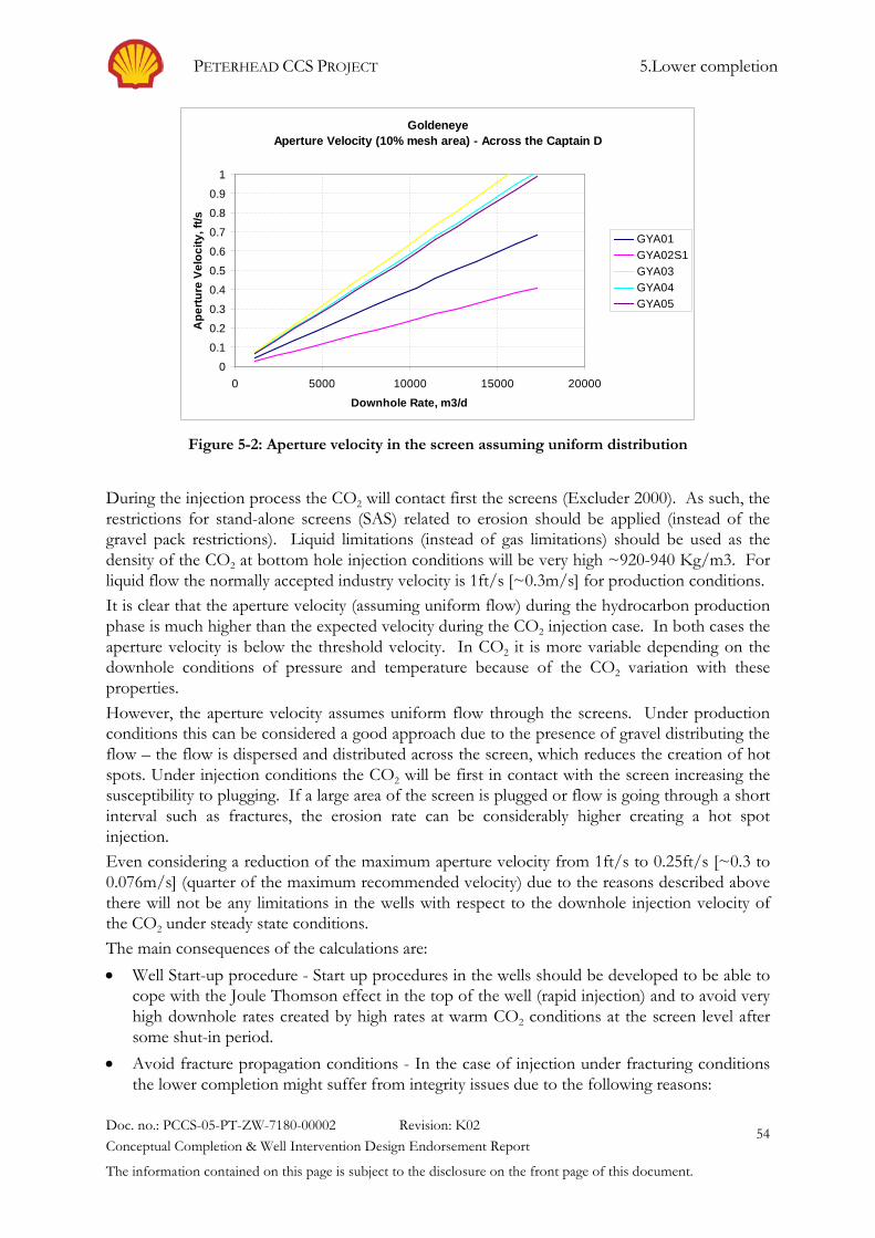
PETERHEAD CCS PROJECT 5.Lower completion
Doc. no.: PCCS-05-PT-ZW-7180-00002 Revision: K02 Conceptual Completion & Well Intervention Design Endorsement Report
The information contained on this page is subject to the disclosure on the front page of this document.
54
Figure 5-2: Aperture velocity in the screen assuming uniform distribution
During the injection process the CO2 will contact first the screens (Excluder 2000). As such, the restrictions for stand-alone screens (SAS) related to erosion should be applied (instead of the gravel pack restrictions). Liquid limitations (instead of gas limitations) should be used as the density of the CO2 at bottom hole injection conditions will be very high ~920-940 Kg/m3. For liquid flow the normally accepted industry velocity is 1ft/s [~0.3m/s] for production conditions. It is clear that the aperture velocity (assuming uniform flow) during the hydrocarbon production phase is much higher than the expected velocity during the CO2 injection case. In both cases the aperture velocity is below the threshold velocity. In CO2 it is more variable depending on the downhole conditions of pressure and temperature because of the CO2 variation with these properties. However, the aperture velocity assumes uniform flow through the screens. Under production conditions this can be considered a good approach due to the presence of gravel distributing the flow – the flow is dispersed and distributed across the screen, which reduces the creation of hot spots. Under injection conditions the CO2 will be first in contact with the screen increasing the susceptibility to plugging. If a large area of the screen is plugged or flow is going through a short interval such as fractures, the erosion rate can be considerably higher creating a hot spot injection. Even considering a reduction of the maximum aperture velocity from 1ft/s to 0.25ft/s [~0.3 to 0.076m/s] (quarter of the maximum recommended velocity) due to the reasons described above there will not be any limitations in the wells with respect to the downhole injection velocity of the CO2 under steady state conditions. The main consequences of the calculations are: • Well Start-up procedure - Start up procedures in the wells should be developed to be able to
cope with the Joule Thomson effect in the top of the well (rapid injection) and to avoid very high downhole rates created by high rates at warm CO2 conditions at the screen level after some shut-in period.
• Avoid fracture propagation conditions - In the case of injection under fracturing conditions the lower completion might suffer from integrity issues due to the following reasons:
GoldeneyeAperture Velocity (10% mesh area) - Across the Captain D
0
0.1
0.2
0.3
0.4
0.5
0.6
0.7
0.8
0.9
1
0 5000 10000 15000 20000
Downhole Rate, m3/d
Ape
rture
Vel
ocity
, ft/s
GYA01GYA02S1GYA03GYA04GYA05

PETERHEAD CCS PROJECT 5.Lower completion
Doc. no.: PCCS-05-PT-ZW-7180-00002 Revision: K02 Conceptual Completion & Well Intervention Design Endorsement Report
The information contained on this page is subject to the disclosure on the front page of this document.
55
- CO2 flow into the fracture and hot spot erosion The CO2 will be injected through the two wings of the created fracture. The CO2 velocities will be extremely high and screen erosion might occur. The normal width of a fracture is in the order of 1'' to 2'' [25-51mm]. Holes in the screen can be developed, screen integrity is lost and then injectivity problems can happen. - Gravel might be displaced into the fracture There have been some cases reported where the gravel has been displaced from the annulus space between the hole and the screen inside the propagating fracture. This will result in the screens not having gravel behind them. The 20/40 gravel installed in Goldeneye is small enough to be transported into the potentially created fracture.
5.5.4. Hydrates The formation of hydrates is only possible when water is present in sufficiently significant quantities and the temperature and pressure of the fluid is within the hydrate formation window. During hydrocarbon production, water has encroached into the Goldeneye gas cap and at least part of the well gravel pack will be surrounded by water at the time that injection commences. The trapped gas saturation is estimated to be 25%, so some methane will remain near the well. The methane is miscible with CO2 and consequently will eventually be displaced by the injected CO2. The initial injection of CO2 will drive water away from a well and cool the reservoir. The cooling of the injection well and the surrounding reservoir matrix induced by the injection of CO2 does have the potential to create conditions favourable for the formation of hydrates In order to reduce the initial risk of hydrate formation during the first years of injection (once water is displaced from the wellbore) it is considered prudent to introduce batch hydrate inhibition prior to operational opening of a well for injection purposes. If water is subsequently introduced into a well and/or it is suspected that water is present in a wellbore, then batch injection should continue. Methanol is currently preferred as an inhibitor and this will be supplied to the platform via the 4'' [102mm] piggybacked supply pipeline from St Fergus. Batch hydrate inhibition will feature as an instruction in the well operational procedures that will be developed for the injection system
5.5.5. Injection Experience with Sand Control Baker (the supplier of the screens) has indicated that the screen can be used for CO2 injection. There will be no modifications required to use the Excluder2000 screen for injection purposes. There is experience in water injection projects with similar kind of screens. The main operating practice in water injection projects with sand control is safeguarding the injection system by having a tight control in the water specifications namely solids content and size. In some Shell projects the water specification calls for a maximum particle size of 5 micron. Normal practice is in the order of 17 microns.
5.5.6. Flow Reversing (production – injection) By reversing the flow from the production hydrocarbon production phase to the CO2 injection phase, there might be some re-accommodation of fines currently embedded in the gravel pack under hydrocarbon production. Sand failure had occurred in Goldeneye due to the level of depletion and the rock strength. Fines have been trapped / embedded in the gravel pack, which is designed for this function. The well productivity has not decreased with time.

PETERHEAD CCS PROJECT 5.Lower completion
Doc. no.: PCCS-05-PT-ZW-7180-00002 Revision: K02 Conceptual Completion & Well Intervention Design Endorsement Report
The information contained on this page is subject to the disclosure on the front page of this document.
56
These formation fines embedded in the gravel pack can get mobilized against the formation (like an external filter cake) and create an additional pressure drop reducing the injectivity in the well. The effect of this pressure drop is considered low due to the following reasons: • Well productivity stable with time - indication of a limited volume of fines being trapped
with time as the pressure drop in the wellbore has been stable. • Captain D is well sorted sandstone - completed in the top of the D sand where the sand
sorting is better. Fines percentage in the Captain D is very small • Gravel pack designed considering the general criteria in the oil industry - gravel can have
formation particles (principle of the gravel pack / screens) • Industry experience in underground storage with sand control
A remedial activity in the case of finding this issue is by side-tracking the well to avoid the trapping of solids in the lower completion during the production phase.
5.6. Well Selection Basis The priority for the well selection is based on well position in the reservoir. Considering ONLY the lower completion, then CO2 should preferably be injected first in wells with long screens; there will be more plugging allowance and a lower screen velocity. Wells with a better gravel pack operation should be given priority to decrease the risk of failure and or reduction of the drawdown, which might be applied. Consideration should also be given to the complexity of the initial well modification for CCS. In summary, the priority of injection should be as follows:
1. GYA- 01. Long screens but current packer needs to be removed to install a new one at the Hidra formation
2. GYA-03 and GYA04. Short screen but workover can be relatively easy leaving the current packer in place
3. GYA-05. Short screen and current packer needs to be removed to install a new one at the Hidra formation
4. GYA-02S1. Longest screens but problems during the gravel pack operation impose drawdown limitations. Workover can be relatively easy leaving the current packer in place.

PETERHEAD CCS PROJECT 6.Goldeneye Well Upper Completions
Doc. no.: PCCS-05-PT-ZW-7180-00002 Revision: K02 Conceptual Completion & Well Intervention Design Endorsement Report
The information contained on this page is subject to the disclosure on the front page of this document.
57
6. Goldeneye Well Upper Completions This section evaluates the suitability of the current Goldeneye platform wells upper completions for CO2 injection and long term exposure to CO2
The following paragraphs highlight some of the concerns with the current design and materials used in the existing completions, the most critical being the Joule Thomson cooling and associated effects. A review of these concerns leads to the conclusion that the existing upper completion is not suitable for the project and shall hence require to be changed out, i.e. an upper completion workover is necessary.
6.1. Current Well Integrity Concerns Well integrity tests (WITS) are carried out on an annual basis. All well integrity information is captured and stored in eWIMS (global electronic database that captures well integrity data for Shell operated wells) under the responsibility of a Well Integrity Focal Point. Additionally, the control room monitors annulus pressure gauges on all wells continuously, with alarms at predetermined levels, and the data stored in RTMS. None of the wells is subject to any known major integrity issues. An intervention campaign was carried out in 2012 and suspension plugs were set in all the wells. At the time some safety valve control line integrity issues were noted on wells GYA01 and 03. Corrective measures were also required to some FWV and UMV stem seals. This was carried out during subsequent intervention trips in Nov 2012 and February 2013. From table 6-2 it can be seen that this work ties in with the wells suspension activities. In a number of wells (GYA 02, 04 and 05) the lowermost suspension plug was set above the downhole gauge thereby allowing the reservoir pressure and temperature to be monitored.
Table 6-1: Well Integrity Overview – eWIMS data
General Tubing A Annulus B Annulus Well
Name
Stat
us
Tub
ing
OK
MA
ASP
[bar
a]
Trig
ger [
bara
]
Min
[bar
a]
Act
ual r
eadi
ng
[bar
a]
Rec
ordi
ng d
ate
MA
ASP
[bar
a]
Trig
ger [
bara
]
Min
[bar
a]
Act
ual r
eadi
ng
[bar
a]
Rec
ordi
ng d
ate
GYA01 Suspended Y 206 103 10 30 12/19/2013 22
19 2 5 12/19/2013
GYA02S1 Suspended Y 206 103 10 16 12/19/2013 8 7 2 3 12/19/2013
GYA04 Suspended Y 206 103 10 22 12/19/2013 17
15 2 6 12/19/2013
GYA05 Suspended Y 206 103 10 22 12/19/2013 22
19 2 8 12/19/2013
GYA03 Suspended Y 206 103 10 21 12/19/2013 8 7 2 4 12/17/2013

PETERHEAD CCS PROJECT 6.Goldeneye Well Upper Completions
Doc. no.: PCCS-05-PT-ZW-7180-00002 Revision: K02 Conceptual Completion & Well Intervention Design Endorsement Report
The information contained on this page is subject to the disclosure on the front page of this document.
58
GYA 01 & 03 GYA 02& 05 GYA 04
Figure 6-1: Wells Suspension Status
Table 6-2: Well Suspension Plugs – Setting Depths (ft) [1ft = 0.3048m]
GYA01 GYA02 GYA03 GYA04 GYA05
Suspended Nov 2012 May 2012 April 2012 May 2012 Feb 2013
Plug 01 139ft 124ft 134ft 118ft 148ft
Plug 02 2669ft 10362ft 2618ft 2976ft 7731ft
Plug 03 8595ft 9017ft
Gas migration through SSSV control line
Gas migration through SSSV control line
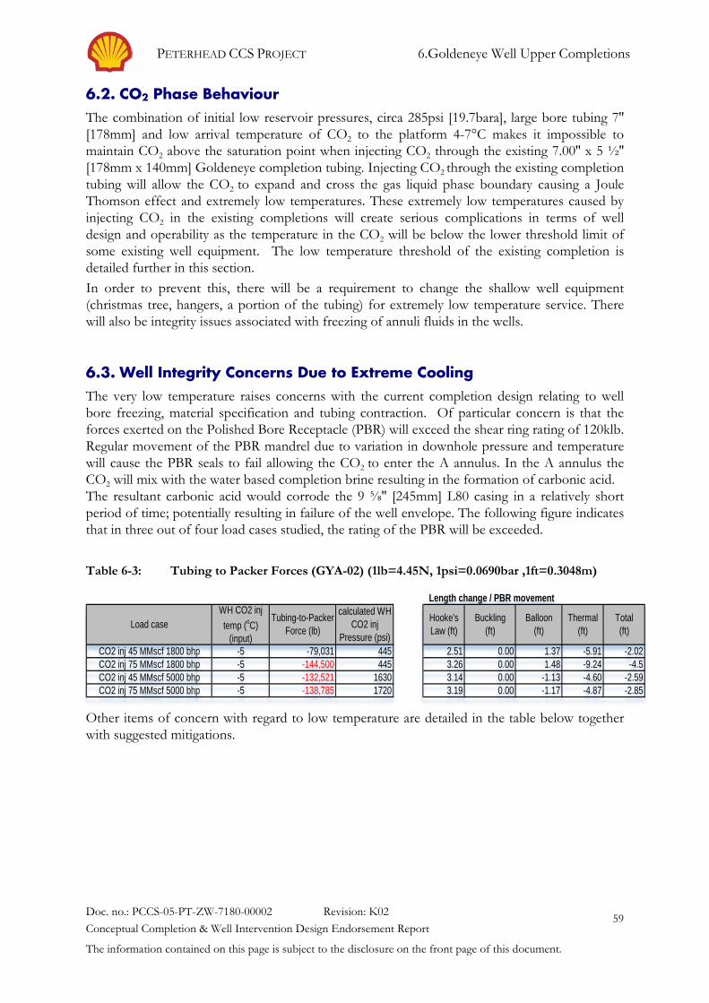
PETERHEAD CCS PROJECT 6.Goldeneye Well Upper Completions
Doc. no.: PCCS-05-PT-ZW-7180-00002 Revision: K02 Conceptual Completion & Well Intervention Design Endorsement Report
The information contained on this page is subject to the disclosure on the front page of this document.
59
6.2. CO2 Phase Behaviour The combination of initial low reservoir pressures, circa 285psi [19.7bara], large bore tubing 7'' [178mm] and low arrival temperature of CO2 to the platform 4-7°C makes it impossible to maintain CO2 above the saturation point when injecting CO2 through the existing 7.00'' x 5 ½'' [178mm x 140mm] Goldeneye completion tubing. Injecting CO2 through the existing completion tubing will allow the CO2 to expand and cross the gas liquid phase boundary causing a Joule Thomson effect and extremely low temperatures. These extremely low temperatures caused by injecting CO2 in the existing completions will create serious complications in terms of well design and operability as the temperature in the CO2 will be below the lower threshold limit of some existing well equipment. The low temperature threshold of the existing completion is detailed further in this section. In order to prevent this, there will be a requirement to change the shallow well equipment (christmas tree, hangers, a portion of the tubing) for extremely low temperature service. There will also be integrity issues associated with freezing of annuli fluids in the wells.
6.3. Well Integrity Concerns Due to Extreme Cooling The very low temperature raises concerns with the current completion design relating to well bore freezing, material specification and tubing contraction. Of particular concern is that the forces exerted on the Polished Bore Receptacle (PBR) will exceed the shear ring rating of 120klb. Regular movement of the PBR mandrel due to variation in downhole pressure and temperature will cause the PBR seals to fail allowing the CO2 to enter the A annulus. In the A annulus the CO2 will mix with the water based completion brine resulting in the formation of carbonic acid. The resultant carbonic acid would corrode the 9 ⅝'' [245mm] L80 casing in a relatively short period of time; potentially resulting in failure of the well envelope. The following figure indicates that in three out of four load cases studied, the rating of the PBR will be exceeded.
Table 6-3: Tubing to Packer Forces (GYA-02) (1lb=4.45N, 1psi=0.0690bar ,1ft=0.3048m)
Other items of concern with regard to low temperature are detailed in the table below together with suggested mitigations.
CO2 inj 45 MMscf 1800 bhp -5 -79,031 445 2.51 0.00 1.37 -5.91 -2.02CO2 inj 75 MMscf 1800 bhp -5 -144,500 445 3.26 0.00 1.48 -9.24 -4.5CO2 inj 45 MMscf 5000 bhp -5 -132,521 1630 3.14 0.00 -1.13 -4.60 -2.59CO2 inj 75 MMscf 5000 bhp -5 -138,785 1720 3.19 0.00 -1.17 -4.87 -2.85
Total(ft)
calculated WH CO2 inj
Pressure (psi)
Length change / PBR movement
Hooke'sLaw (ft)
Buckling(ft)
Balloon(ft)
Thermal(ft)Load case Tubing-to-Packer
Force (lb)
WH CO2 inj temp (oC)
(input)

PETERHEAD CCS PROJECT 6.Goldeneye Well Upper Completions
Doc. no.: PCCS-05-PT-ZW-7180-00002 Revision: K02 Conceptual Completion & Well Intervention Design Endorsement Report
The information contained on this page is subject to the disclosure on the front page of this document.
60
Table 6-4: Low Temperature Threshold of Current Completion Equipment
Item of Equipment Lower Temperature Limit
Remarks/Mitigation
Cameron Christmas tree block
-18 °C Predicted temperature (-25°C) is colder than low temperature threshold. Current Christmas Tree material can be up graded from 4140 low alloy steel to F6NM stainless steel which has a low temperature threshold of -60°C.
Cameron 3 Stage Compact Spool
-18°C Predicted temperature (-25°C) is colder than low temperature threshold. Compact spool is made from 4130 Low alloy steel and cannot be replaced without adding complexity to the workover operation.
Cameron Tubing Hanger
- 18°C Predicted temperature (-25°C) is colder than low temperature threshold. Tubing hanger material can be upgraded in line with the increased Christmas Tree specification.
Production casing 10 ¾'' x 9 ⅝''
- 40°C Temperature adequate for steady state injection. Potential complicated operation to replace L80 casing in the upper section of the well.
Production Tubing 13Cr L80
-20 to - 30°C More investigation required to confirm the use of this for steady state production. Can be replaced with super 13Cr which has a low temperature threshold of -50°C
A- Annulus Fluid Sea Water
- 1.8 °C Predicted temperature (-25°C) is colder than low temperature threshold. Replace with Base Oil
TRSSSV -7 C Temperature adequate for steady state injection at SSSV depth. Further qualification to be carried out in advance (one year) of workover operations commencing
TRSSSV Control Line Fluid
- 40°C Temperature adequate for steady state injection. Alternative control line fluid to -60°C available
6.4. Tree & Wellhead Concerns The Goldeneye tree/wellhead is a robust system adopting primary metal to metal seals. The tree and wellhead were primarily designed for gas production, which makes it a good candidate for CO2 injection. The three main areas of concern are ED (explosive decompression) resistance, corrosion resistance and low temperature performance.

PETERHEAD CCS PROJECT 6.Goldeneye Well Upper Completions
Doc. no.: PCCS-05-PT-ZW-7180-00002 Revision: K02 Conceptual Completion & Well Intervention Design Endorsement Report
The information contained on this page is subject to the disclosure on the front page of this document.
61
• ED resistance - The tree has provided good ED resistance so far in gas production service. The elastomers, which could be susceptible, are in the annulus regions, which would require breakdown of the primary seals to be exposed. If the elastomers were exposed to an ED environment, they would show signs of ED damage on the side exposed to the gas, however as they are constrained in the groove severe damage does not occur until the seal is removed allowing it to expand and tear as gas escapes from inside the elastomers.
• Corrosion resistance - This tree/wellhead system is material class FF rated, which will be resistant to dry CO2. However if the CO2 becomes wet, it will form carbonic acid, which will corrode carbon steel and depending upon the ph level may corrode stainless steel.
• Low temperature performance - The tree is designed for temperature class U (-18 to 121°C), limited by the bonnet and the tree block, both being 410 stainless steel and temperature class U.
It is anticipated that the tree/wellhead is suited to CO2 injection for the specified steady state operating parameters, only for temperatures down to -18°C. Thermal analysis would be required to verify that that the tree is suitable during the transient condition during valve closure. The integrity of the completion is also paramount to prevent CO2 in the annulus areas. The main issue is that 410 stainless steel has a low Charpy impact value that could generate cracking. The F6NM alternative in ES-002019-01 conforms to API-6A impact requirements. The Christmas tree and tubing hanger will require to be replaced with a lower temperature rated system.
6.5. Upper completion Workover To mitigate against the aforementioned effects it is necessary to design a completion string that will introduce sufficient back pressure to the injection system so that CO2 can be maintained above the critical point in a single dense liquid phase, thus preventing the extreme cooling from the Joule Thomson Effect occurring. A re-completion operation would provide an opportunity to -
• Remove the perforated pup joint between the production packer and the screen hanger
• Optimise the tubing to maintain single phase injection and introduce injection flexibility
• Carry out cement bond logs and casing calliper runs
• Set the new production packer deeper, to be in front of the Hidra seal. Ideally the production packer should be placed in front of the sealing formation. The current packer in the wells GYA01 and GYA05 are across the bottom of the Chalk
• Optimise in-well surveillance.
• Replace components such as christmas tree, tubing hanger, annulus fluid etc. with lower temperature resistant/rated types.

PETERHEAD CCS PROJECT 7.Upper Completion Concepts
Doc. no.: PCCS-05-PT-ZW-7180-00002 Revision: K02 Conceptual Completion & Well Intervention Design Endorsement Report
The information contained on this page is subject to the disclosure on the front page of this document.
62
7. Upper Completion Concepts As discussed in the previous section in order to utilise the Goldeneye wells a workover or replacement of the upper completion is necessary. This section summarises the various completion designs that have been considered during the select phase and the reasons why they were discounted. The considered options are schematically represented in the figure below.
7.1. Completion requirements & Options The principal requirement for each completion type is to promote frictional pressure losses in the tubing so that the injection pressure can be maintained above 50bara. This will ensure that that CO2 can be maintained in the dense liquid phase. Other requirements are;
• Well design: Installation ease, normal practice in the industry and North Sea, reliability of the solution and optimisation opportunities
• Injection Flexibility: Management of injection requirement, flexible injection from the minimum to the maximum of the CCP.
• Well Integrity: Maintain well integrity, carry out prescribed integrity tests
• In- Well monitoring: ability to install and have reliable data from PDGs, DTS, etc.
• Well Intervention: Easiness to intervene the well (wireline, coil tubing)
• Life Cycle Cost: CAPEX, OPEX and abandonment cost
Figure 7-1: Completion Options for CCS

PETERHEAD CCS PROJECT 7.Upper Completion Concepts
Doc. no.: PCCS-05-PT-ZW-7180-00002 Revision: K02 Conceptual Completion & Well Intervention Design Endorsement Report
The information contained on this page is subject to the disclosure on the front page of this document.
63
The available completion options can be divided in two groups:
• Friction dominated concept: small tubing, insert string, dual completion and concentric strings.
• Downhole choke Schematics representing each completion concept are included in Appendix 6.
7.1.1. Single Tapered Tubing (Small Tubing) Under this scenario a single tapered tubing is used in the Goldeneye wells to create the required delta pressure to keep the CO2 in single phase at the wellhead. A minimum rate is imposed per well. The combination of wells will be able to meet the CO2 rates from the capture plant.
Table 7-1: Single Tapered Tubing Evaluation
Criteria Evaluation
Well Design (+) Simple and Standard completion (+) Simple Wellhead Different tubing sizes required (4 ½'' & 3 ½'' [114mm & 89mm]) (-) Small tubing. 3 ½'' is not a common size in the North Sea, but plenty of onshore experience
Injection Flexibility One string per well (+) Combination of wells provides the required injection conditions for the life cycle of the project. (-) Limited range of injection conditions – depends on tubing size (-) Minimum rate required
Well Integrity (+) SSSV setting depth can be optimised (+) corrosion logs possible (+) Pressure Integrity Test is possible. Special tool might me required due to the small tubing size.
In-well monitoring (+) Normal installation. Enough annular space for in-well tools (+) Multiple PDG and DTS can be installed, internal and external readings can be measured
Well Intervention (+) Standard. Limited ID depending on tubing size and FIV (2.94'' [74.7mm])
Life Cycle Cost As a minimum 2 injectors required + 1 back up (+) simple integrity workover (if required) (+) no late workover required to meet CCP rates (+) reduced future abandonment costs and complexity

PETERHEAD CCS PROJECT 7.Upper Completion Concepts
Doc. no.: PCCS-05-PT-ZW-7180-00002 Revision: K02 Conceptual Completion & Well Intervention Design Endorsement Report
The information contained on this page is subject to the disclosure on the front page of this document.
64
7.1.2. Insert String The installation of an insert or velocity string below the SSSV will introduce the required frictional pressure losses into the injection system, thus maintaining the supplied CO2 above the saturation line in the dense liquid phase. The main advantage of the system is the ability to install the SSSV at a depth similar to currently installed SSV in the existing wells.
Table 7-2: Insert String Evaluation
Criteria Evaluation
Well Design (-) Medium complexity, experience in the gas industry with velocity strings (+) Simple wellhead Different tubing sizes required (4 ½'' & 3 ½'' [114mm & 89mm]) in the insert string Hanger inside the tubing is critical. Pressure sealing required in the top of the insert string. Extra stresses created by this configuration. (-) Unable to fix integrity concerns in the completion tubing
Injection Flexibility One string per well. A workover to remove the insert string might be executed to expand the operating envelope of the well once the reservoir pressure increases. More applicable to expansion storage projects. (+) Combination of wells provides the required injection conditions for the life cycle of the project. (-) Limited range of injection conditions – depends on tubing size (-) Minimum rate required (+) Optimisation: Install SSD in the insert string or perforate the insert string to increase the operating envelope
Well Integrity (-) Severe vibration expected. Inner tubing not in tension, free-hanging. Tubing integrity can be lost by the excessive moving and banging into the outer tubing. (+) SSSV depth (-) corrosion logs not possible in the outer string (the tubing providing CO2 containment in the tubing). Corrosion log possible in the inner string. (-) Pressure Integrity Test not possible in all the tubing length (where the insert string is positioned)
In-well monitoring (-) PDG and DTS in the outside tubing. External reading of temperature might not be representative due to the distance to the injected CO2.
Well Intervention (+) Limited ID depending on tubing size and FIV (2.94'' [74.7mm])
Life Cycle Cost As a minimum 2 injectors required + 1 back up (-) Expensive integrity workover (if required) (+) no late workover required to meet CCP rates (-) Slightly more expensive abandonment

PETERHEAD CCS PROJECT 7.Upper Completion Concepts
Doc. no.: PCCS-05-PT-ZW-7180-00002 Revision: K02 Conceptual Completion & Well Intervention Design Endorsement Report
The information contained on this page is subject to the disclosure on the front page of this document.
65

PETERHEAD CCS PROJECT 7.Upper Completion Concepts
Doc. no.: PCCS-05-PT-ZW-7180-00002 Revision: K02 Conceptual Completion & Well Intervention Design Endorsement Report
The information contained on this page is subject to the disclosure on the front page of this document.
66
7.1.3. Dual Completion Each tubing in a dual completion well will introduce the required frictional losses into the injection system. A minimum rate in each string should be maintained to avoid CO2 flashing in the top of the well. The advantage of the system is to expand the operating envelope per well by injecting in one or both tubing strings at the same time. Dual 3 ½'' [89mm] 13Cr tubing and 2 ⅞'' [73mm] 13Cr tubing will meet forecasted injection volumes of CO2 with the use of fewer wells. DTS, PDGs would be able to be incorporated in the well.
Table 7-3: Dual Completion Evaluation
Criteria Evaluation
Well Design (-) High complexity. Low experience in the North Sea with dual strings (-) Dual XM tree required. Long lead item. Goldeneye wellhead is not designed for a dual XM tree and tubing hanger. A new build XM tree is likely to be required. Y-tool preferred over dual packer (stronger completion) (-) impact of tubing stresses when injecting down in the a single string (-) Mechanical barriers to be recovered through small tubing. (-) Congested well bay (dual wellhead + dual flow lines)
Injection Flexibility Two string per well. (+) Increase flexibility per well (3 different injection sizes: tubing1, tubing 2, tubing 1 +2) (-) Minimum rate required (-) More difficult inflow calculation. Total capacity of the well should be approximately ~ 0.85 of the tubing 1 + tubing 2 due to inflow restrictions. (-) Congested well bay
Well Integrity (+) SSSV depth. 2 SSSV per well operating independently. (+) Corrosion log possible (-) Multiple/complex leak paths In case of a tubing failure, injection might continue in the well by isolating the leaking string.
In-well monitoring (-) Limited space in the A-annulus. Ability to install devices depends on the completion size (-) PDG below Y-tool. DTS possible in one or both strings depending on size. Number of penetration increase in the wellhead
Well Intervention (+)Limited ID depending on tubing size and FIV (2.94'' [74.7mm]) (+) 2 strings to get access to the wellbore. However, Y-tool will cancel this option (only one string normally has access to the wellbore)
Life Cycle Cost As a minimum 2 injectors required + 1 back up. Not possible to meet injection expectations with only one well (-) Very expensive initial workover (-) Expensive integrity workover (if required)

PETERHEAD CCS PROJECT 7.Upper Completion Concepts
Doc. no.: PCCS-05-PT-ZW-7180-00002 Revision: K02 Conceptual Completion & Well Intervention Design Endorsement Report
The information contained on this page is subject to the disclosure on the front page of this document.
67
(+) no late workover required to meet CCP rates (-) Expensive abandonment
7.1.4. Concentric Completion The inner string will be run inside the outer tubing string. The advantage of the system is the ability to change injection from the inner tubing to the outer tubing or both expanding the operating envelope per well.
Table 7-4: Concentric Completion Evaluation
Criteria Evaluation
Well Design (-) High complexity completion. No major experience in the hydrocarbon industry with concentric completions (-) Special dual wellhead required (Horizontal tree). Special design and long lead item. The current wellhead is not suitable for running a concentric completion from surface to require depth. Different tubing sizes required (4 ½'' & 3 ½'' [114mm & 89mm]) in the inner string (-) Unable to fix leaking in the completion tubing (-) Deep set SSSV (-) Lots of modifications required to standard practice in the oil industry.
Injection Flexibility Two string per well. (+) Increase flexibility per well (3 different injection sizes: inner, annulus between inner and outer tubing, both)) (-) Minimum rate required (-) More difficult inflow calculation. Total capacity of the well should be approximately ~ 0.85 of the tubing 1 + tubing 2 due to inflow restrictions. (-) Congested well bay
Well Integrity (-) Severe vibration expected. Inner tubing not in tension, free-hanging. Tubing integrity can be lost by the excessive moving and banging into the outer tubing. This can be considered as a showstopper for this kind of completion. (-) SSSV depth. The SSSV can be installed below the inner string. No remedial activities in the SSSV due to the ID restriction of the concentric string. The valve is set very deep with larger CO2 inventory. (-) corrosion logs not possible in the outer string (the tubing providing CO2 containment in the tubing). Corrosion log possible in the inner string. (-) Pressure Integrity Test not possible in all the tubing length (where the insert string is positioned)
In-well monitoring (+) Existing completion (7'' [178mm]) with PDG and cable. (-) PDG and DTS in the outside tubing. External reading of temperature might not be representative due to the distance to the injected CO2.
Well Intervention (+) Limited ID depending on tubing size and FIV (2.94'' [74.7mm])

PETERHEAD CCS PROJECT 7.Upper Completion Concepts
Doc. no.: PCCS-05-PT-ZW-7180-00002 Revision: K02 Conceptual Completion & Well Intervention Design Endorsement Report
The information contained on this page is subject to the disclosure on the front page of this document.
68
Life Cycle Cost As a minimum 2 injectors required + 1 back up (-) Expensive integrity workover (if required) (+) no late workover required to meet CCP rates (-) Expensive abandonment
7.1.5. Downhole choke Under this scenario, a tubing retrievable downhole choke is installed which creates the delta pressure required to manage the CO2 in dense phase along the well. It may be possible to control the choke from surface via a hydraulic control line. Multiple chokes may be deployed. Normally the downhole choke should be installed at a depth where no phase changes can occur to avoid vibration and cavitation. For Goldeneye wells this is deep in the well.
Table 7-5: Downhole Choke Evaluation
Criteria Evaluation
Well Design Smart application. (-) Control line requirement. Proven technology for inflow control modifications where small delta P is required. In our case high delta P is required across the device. (-) Wellhead with more penetrations (special hangers or modifications required). (+) Normal tubing size of the North Sea Small chokes required (6/64th '' – 11/64th '' [2.38 – 4.37mm]) (-) Prone to choke erosion and plugging Placement not very critical of the choke. In the dense phase (deep in the well). Optimisation: Installation of multiple downhole chokes
Injection Flexibility One string per well. Large pressure drop in the downhole chokes. (-) Big change of operating range with small changes in size diameter. (-) Pressure and Temperature drop across the choke might increase the potential for hydrate deposition. Late injection will not require downhole chokes as the reservoir pressure will increase.
Well Integrity (+) Standard SSSV (-) Corrosion log and Pressure integrity test possible above the choke. Not possible below the choke.
In-well monitoring Same as single tapered tubing (+) Normal installation. Enough annular space for in-well tools
Well Intervention (-) Partial. No access to the reservoir. Access below the choke will depend on choke type.
Life Cycle Cost As a minimum 2 injectors required + 1 back up
PETERHEAD CCS PROJECT 7.Upper Completion Concepts
Doc. no.: PCCS-05-PT-ZW-7180-00002 Revision: K02 Conceptual Completion & Well Intervention Design Endorsement Report
The information contained on this page is subject to the disclosure on the front page of this document.
69
(+) no late workover required to meet CCP rates (-)High chance of well activities to change downhole chokes (-) Smart application. Expensive workover
7.2. Wellhead & Christmas Tree The current Goldeneye wellhead is a Cameron supplied, 18 ¾'' [476.25mm] SSMC compact Wellhead. The christmas tree is a Cameron 5,000 psia [345bara], FFY type, c/w 6 ⅜'' [162mm] FLS type gate valves, 18 ¾'' x 5,000psi [476.25mm x 345bara] fast lock connection bottom and 7 1/16'' [179mm] API 5,000 psia studded connection top. The tree is manufactured to PSL 3 (Product Service Level 3), Temperature class ''U'' (-18°C to 150°C), material class FF (stainless Steel Trim). Hydraulically actuated valves use Shell Tellus, T15 hydraulic fluid (oil based) as an operating medium. The 18 ¾'' SSMC type wellhead has two exit penetrations for TRSSSV C/L and PDGM signal cable.
7.2.1. Dual Completion The Goldeneye wellhead is not designed for a dual Christmas tree and tubing hanger. There is no facility to orientate a dual tubing hanger when landing off inside the 18 ¾ [476.25mm] SSMC style wellhead, i.e. there is no guide pin in the wellhead or orientation slot in the current tubing hanger running tool. Consequently, it would be very difficult to plan in advance for the final orientation of a dual Christmas tree and the routing of flow lines and surface control equipment. Furthermore, it is not possible to lock a dual tubing hanger in place inside the current wellhead configuration Discussions between Shell and representatives from Cameron Limited concluded that if a dual Christmas tree is required for Goldeneye CCS operations consideration should be given to commissioning a complete new build. A new build dual Christmas tree will ensure that the following requirements are engineered into the design. Orientation facility. Tubing hanger running and orientation tool. Method of locking the tubing hanger in place. Additional penetrations for Distributed Temperature System (DTS) and Permanent
Downhole Gauge Monitoring (PDGM). Approximately 1 ½ to 2 years are required for design, manufacture and FAT testing.
7.2.2. Concentric completion The Goldeneye wellheads and Christmas trees in their current configurations are not suitable for running a concentric completion from surface to required depth. There is currently no field proven method of hanging off a capillary sting inside the current Goldeneye wellhead while retaining the facility to inject down both the inner and outer strings. For it to be possible to hang off a capillary string inside the existing Goldeneye 7.00'' x 5 ½'' [178mm x 140mm] completion tubing an additional 7 1/16'' [179mm] API 5,000 psia spool piece c/w tubing hanger profile, lock down facility and flow line connection will be required. Although this type of operation has been carried out before within Shell, it is not a standard operation and there is currently no standard equipment that is fit for purpose. A new/modified
PETERHEAD CCS PROJECT 7.Upper Completion Concepts
Doc. no.: PCCS-05-PT-ZW-7180-00002 Revision: K02 Conceptual Completion & Well Intervention Design Endorsement Report
The information contained on this page is subject to the disclosure on the front page of this document.
70
spool piece that is compatible with the existing Goldeneye Christmas trees will have to be designed and manufactured. As the capillary tubing will be run through the original Christmas tree valves and TRSSSV, effectively making them redundant, it is almost certain that a SCSSSV & ASV system will be required to mitigate against uncontrolled release of CO2 at surface. Incorporating control line exits into the system is an additional challenge has potential to add significant cost and time to the project. The additional spool piece will also raise the height of the flow line necessitating changes to the configuration of the existing flow lines. Additionally it will reduce the available height for installation of wireline logging tool strings. Another option under consideration when installing a capillary string to surface is the Weatherford renaissance system; a system where by a capillary string incorporating a SCSSSV can be run in to the existing 7.00'' x 5 ½'' completion tubing. The inclusion of a SCSSSV which is set inside the original Goldeneye TRSSSV precludes any possibility of injecting down the capillary string x 7.00'' tubing annulus.
7.2.3. Single Tapered Tubing The existing Goldeneye wellhead has two wellhead penetrations that are used for TRSSSV and PDGM. Should the wells be worked over and re-completed with small bore tubing there may be a requirement for an additional penetration for a DTS fibre optic cable so that the injection well can be monitored for leakage of CO2 in to the Annulus. Although it is not possible to retro fit an additional penetration to the 18 ¾'' [476.25mm] SSMC style wellhead, it is possible to add one or more wellhead penetrations to the 18 ¾'' fast lock connector on the bottom of the Goldeneye style christmas tree, modifications to the existing style tubing hanger will also be required. After six years of sustained gas production it is not known if the condition of the existing Goldeneye christmas trees are suitable for injection of CO2 over the planned 15 to 20 year life cycle. A new Christmas tree with lower temperature rating shall be required.
7.2.4. Insert String & Downhole choke No changes required to current Christmas tree or flow line configuration for both of these options. It is possible to run the insert string through the current 6 ⅜'' [162mm] Christmas tree. The downhole choke option would require some modifications to accommodate for the extra control lines. Systems do exist which would allow for multiple chokes to be deployed on a reduced number of lines, the exact number of penetrations is yet to be defined, however it is likely to be more than the current scope allows for.
7.3. Comparison of Completion Concepts - Discussion The initial installation of the single tapered completion option is the simplest and most robust. The other systems present extra challenges / cost in comparison to the single tapered completion, specially related to the wellhead and christmas tree system (for dual completion and concentric string). For the insert sting option, the inner string hanger is critical to the CO2 management. The downhole choke would require special control lines and increased penetrations depending on the number of chokes to be installed. For all the friction dominated completions there will be a minimum injection rate. The injection flexibility in the single tapered system can be managed with the number of wells. The other

PETERHEAD CCS PROJECT 7.Upper Completion Concepts
Doc. no.: PCCS-05-PT-ZW-7180-00002 Revision: K02 Conceptual Completion & Well Intervention Design Endorsement Report
The information contained on this page is subject to the disclosure on the front page of this document.
71
friction dominated systems present more flexibility in terms of number of injection conduits per well. However, the combination of different wells with different injection characteristics will be able to accommodate the varying rates from the capture plant during the life cycle. The downhole choke option may have issues regarding well envelopes in case of erosion/abrasion of the choke (small changes in choke size can have significant changes in pressure drop and hence unpredictable envelopes). The well integrity management in single completion is ideal; position of all the safety devices is robust and the production packer can be optimally placed based on cement bond and casing calliper logs. The insert string and concentric string options presents a serious integrity problem related to the vibration of the inner string when injecting high velocity CO2. The position of the SSSV in the concentric string is critical as the depth would be very close to the reservoir. The number of potential leak paths is high for dual completions. A pressure integrity test in the downhole choke option would be challenging below the valve if it is not possible to retrieve the valve. The single completion tubing and the downhole choke completion present the best option for in-well monitoring. The in-well monitoring is not ideal in the insert and concentric strings as the temperature information is from the outer tubing string. Depending on tubing size there might not be enough space for accommodating all the required devices in a dual completion. The well intervention for the friction dominated completion concepts is similar. Dual completion options present slightly less than ideal conditions due to the intervention being possible in only one string if Y-tool options is selected. In the single tapered tubing the only restriction for well intervention is related to the tubing size (potential landing nipples) and deep in the well by the FIV. The downhole choke option will have limitations in easy intervention as the restriction would require to be removed prior to any intervention. The life cycle cost is influenced primarily by the cost of the initial installation and future workovers. The number of wells does not have a major influence as the storage license will cover all five existing wells. A traffic light system can be used to visualise the advantages and disadvantages of the different completion systems. Green represents ideal conditions and red represent a serious concern.
Table 7-6: Completion Concept Selection – visualisation
ConcernSmall Tubing Big tubing +
Doable (Tapered) Insert String Dual completion Concentric Downhole choke(Smart)
Ideal
Well Design
Injection Flexibility
Well Integrity
In-well monitoring
Well Intervention
Life Cycle Cost

PETERHEAD CCS PROJECT 8.Selected Upper Completion Concept
Doc. no.: PCCS-05-PT-ZW-7180-00002 Revision: K02 Conceptual Completion & Well Intervention Design Endorsement Report
The information contained on this page is subject to the disclosure on the front page of this document.
72
Considering the discussion above the single tapered completion concept has been selected.
8. Selected Upper Completion Concept Modifications are required to ensure well integrity and create frictional pressure losses into the injection system, creating a backpressure at surface sufficient to maintain the supplied CO2 above the gas liquid phase boundary in the dense liquid phase, thus minimising the effects of low temperature in the well due to the Joule Thomson effect. Modelling has shown that the optimum method for creating backpressure in the system is to re-complete the Goldeneye wells with small-bore tubing. For the reasons based on the comparison carried out in the previous section the single tapered string option has been selected as the optimum solution. Under this scenario a single tapered tubing string is used in all the wells to create the required delta pressure to keep the CO2 in single phase at the wellhead. The string will comprise of 4 ½ and 3 ½ inch tubing. In order to maintain the CO2 in a single dense liquid phase a minimum rate is imposed per well. By changing the setting depth of the tubing crossover each well can have its own individual operating envelope. By injecting into a combination of wells the overall operating envelope will allow for flexibility to handle the varying range of CO2 delivered from the capture plant. This design will allow for standardisation of the well components, the variable would be the placement of the tubing crossover. In addition the monitoring well may have some enhanced instrumentation. This has to be defined in the FEED phase. Changing out the tubing string allows for wireline logging runs for cement bond evaluation to be carried out along with casing calliper runs. This will allow for optimisation of the production packer setting depth. The ideal placement of the production packer would be across the impermeable Rodby shale; however this is not possible as existing screen hanger is set in the Hidra formation immediately above the Rodby shale. The production packers can be set across the Hidra Marl which has been deemed suitable for this requirement. The Hidra Marl along with the Rodby Shale forms the main seal above the Captain Reservoir. In the case of GYA 01 and 05 this would mean setting the new production packer deeper than the existing production packers, i.e. setting the packers in a section of casing that has previously been exposed to the production fluids due to the inclusion of a perforated pup joint in the existing completion design. It is therefore essential to evaluate the condition of this section of casing and to carry out any required remedial work. When the wells were originally drilled and completed cement bond logging was not carried out. Records of the cementing operation have been kept and theoretical top of cements are documented, however the workover would provide an opportunity to carry out cement evaluation and determine the top of cement. The cement bond logs along with the casing evaluation and final position of all the production packers will help align the Goldeneye wells with the abandonment philosophy outlined in document no. PCCS-05-PT-ZW-7180-00001, Abandonment Concept for Injection Wells. The packer fluid will be selected during the FEED phase, the considerations and options that are being evaluated are discussed further in this section. It may be necessary to include a circulation

PETERHEAD CCS PROJECT 8.Selected Upper Completion Concept
Doc. no.: PCCS-05-PT-ZW-7180-00002 Revision: K02 Conceptual Completion & Well Intervention Design Endorsement Report
The information contained on this page is subject to the disclosure on the front page of this document.
73
sub above the production packer to allow the selected packer fluid to be circulated however every measure to avoid this will be taken. The proposed upper completion design will seal inside the lower completion PBR and will not include a perforated pup, thereby containing all the wellbore fluids within the tubing and protecting the entire casing above the screen packer from CO2 and the resultant carbonic acid. This will help ensure longevity and well integrity; this does however create a trapped volume between the two packers. Measures to mitigate against this will have to be explored during the FEED phase and may lead to the inclusion of a pressure relief valve. Another option that will be explored during the FEED phase is to remove the trapped volume all together. Under this option the upper completion will not seal inside the lower completion. A stinger shall be included in the upper completion and this shall enter the lower completion thereby providing a conduit but not a seal. The length of this conduit/stinger is critical and shall have to be sufficient to avoid any active wetting of the CS casing that shall be exposed below the new production packer. Feasibility of this will be reviewed during the FEED. The selected option allows for the deployment of permanent downhole pressure and temperature gauges. These are attached to mandrels which form part of the tubing string and are powered and communicate via a dedicated electric control line to surface. Multiple gauges can be deployed on a single line. Deployment of such systems is standard practice within the North Sea and knowledge of this exists within Shell. Also to be evaluated during the FEED phase is wireless monitoring systems which offer advantages such as ease of deployment and reduce the number of hanger penetrations required, but these systems have a finite battery life, Pressure and temperature modelling suggests that the BHT (Bottom Hole Temperature) is likely to be in the region of 17°C-35°C [63- 95°F]. The selected gauge shall have to be calibrated for this temperature range. It is proposed to include at least two pressure and temperature gauges in each well which shall allow for an inferred density measurement. In one of the injection wells are third gauge shall be installed close to the 4 ½ x 3 ½ [114mm & 89mm] crossover to help understand the CO2 phase behaviour and help calibrate the injection rates. The concept also allows for the inclusion of fibre optic monitoring systems that can provide distributed temperature measurements (DTS) across the entire length of the completion, allowing for well integrity monitoring, and injection optimising and early detection of potential issues. Acoustic/vibration sensing may also be incorporated within this monitoring package. The monitoring well may incorporate additional instrumentation in comparison to the injection wells. Installing a new completion means critical items such as the downhole safety valve which forms part of the ESD system can be placed at the most optimal depth. The formation of hydrates has been identified as a potential concern; this along with other requirements will determine the new setting depths for the safety valves. The SSSV shall be positioned deep enough in the well so as to be unaffected by the same failure mechanisms that can compromise surface ESD systems, and shallow enough that closure times are not compromised by having to overcome high hydrostatic pressures in the control line and to facilitate the testing of the valve by reducing the volume to bleed off. Control line fluid (Castrol Brayco Micronic SV/3) is currently qualified for operations covering the temperature range of -40°C to 200°C [-40°F to 392°F], Castrol Brayco SV/3 has a low pour (<-50°C [<-58°F]) point making it suitable for operations in low ambient temperatures. Changing the original upper completion will allow for a new safety valve control line to be run as part of the new completion, this will allow for the control line material and fluid to be optimised for the new well conditions.

PETERHEAD CCS PROJECT 8.Selected Upper Completion Concept
Doc. no.: PCCS-05-PT-ZW-7180-00002 Revision: K02 Conceptual Completion & Well Intervention Design Endorsement Report
The information contained on this page is subject to the disclosure on the front page of this document.
74
Testing of the SSSV is predicted to be a lengthy operation (24-40hours) especially when the tubing between the valve and the wellhead is filled with dense CO2. In order to minimize this time the top of the tubing is proposed to be 4 ½'' [114mm] tubing rather than 5 ½'' [140mm]. Modelling has revealed that the most severe effects due to the JT cooling occur in the tubing above the safety valve; therefore the option of using Super 13Cr tubing above the safety shall be evaluated during the FEED phase. The generally accepted low temperature limit for 13Cr steel is from -10 to -30°C (depending on manufacturer) and for Super 13Cr it is estimated at -50°C. In any case, impact testing of 13Cr or Super 13Cr tubing will be required for equipment to be run in the wells (especially in the top part of the wells, where extreme low temperatures are expected during the transient). The Christmas tree and tubing hanger shall be changed to low temperature compatible materials and service class. Any elastomers used in components such as packers and tree valves etc which come in contact with CO2 or the JT associated low temperatures can be selected with these specific concerns in mind thereby mitigating against effects such as explosive decompression. Elastomers lose flexibility at low temperatures with reduced or failing sealing as a result. The elastomers selected must be adequate for the corresponding piping class and their suitability for CO2 service has to be analysed.
The proposed upper completion addresses all the concerns highlighted in section 6
• The upper completion design will bring the JT cooling effect within manageable levels
• The upper completion and selected packer fluid will protect the carbon steel casing.
• The production packers will be set deep in the Hidra Marl.
• Cement bond logs and casing calliper runs will be carried out. Safety valve setting depths will be optimised
• Well monitoring for early failure detection will be installed
• The monitoring capability will further allow calibration of the injection rates
• The tubing above the safety valve, the tubing wellhead and Christmas tree will be replaced with suitable low temperature class of service equipment.
• Elastomers will be replaced with suitable compounds to mitigate against explosive decompression
The single string completion is considered to be the best solution for CO2 injection operations for the following reasons: Solution for the lifecycle of the well, no late life workover are foreseen Minimum modifications required to christmas tree and well head All monitoring requirements PDGM / DTS can be accommodated. Best solution for well intervention operations, Coiled Tubing, Wireline Etc. Least complex of all the options considered Packer setting depth can be optimised for final abandonment. PBR removed, no elastomeric sealing elements above the production packer.

PETERHEAD CCS PROJECT 8.Selected Upper Completion Concept
Doc. no.: PCCS-05-PT-ZW-7180-00002 Revision: K02 Conceptual Completion & Well Intervention Design Endorsement Report
The information contained on this page is subject to the disclosure on the front page of this document.
75
Figure 8-1: Proposed Completion Schematic

PETERHEAD CCS PROJECT 8.Selected Upper Completion Concept
Doc. no.: PCCS-05-PT-ZW-7180-00002 Revision: K02 Conceptual Completion & Well Intervention Design Endorsement Report
The information contained on this page is subject to the disclosure on the front page of this document.
76
8.1. Packer Fluid requirement Basic completion fluid requirements for Goldeneye Wells: • Avoid / minimize Corrosion in tubing / production casing. Effect of completion fluid on
tubing material should be minimal • The rheological properties of the packer fluid should be stable during injection period • It should have low freezing point to cope with the well transient conditions and should be
stable in terms of phase envelope • The fluid should be solid free • The target is to have some pressure (5-10 bara) in the A-annulus during the shut-in and
injection conditions The options of using Brines such as Calcium bromide and Calcium chloride are being evaluated as they offer a low crystallization point, around -50°C. In the case of a small leak (tubing to annulus) the CO2 can saturate the brine and lead to a corrosive environment. In order to design this scenario out oil Based packer fluids will also be evaluated This will be reviewed during the FEED phase and an optimal solution will be selected. The bottom hole temperature and therefore the iso-thermal gradient will decrease from initial conditions at circa 85°C to steady state injection conditions of circa 20°C - 40°C. Consequently the fluid in the ''A'' Annulus will shrink as cold CO2 is injected into the well. As the fluid in the annulus shrinks (by approx. 300ft [91.44m]) a vacuum will be created in the upper section of the well tubing/casing annulus. While a vacuum may act as an insulator for the upper section of the well during transient conditions, normal practise is to try and maintain a positive pressure on the annulus as a first indication of tubing to annulus communication. Topping up the annulus and applying a pre-set reference pressure is a suitable solution for steady state injection operations. Should the well be closed in for any length of time, the well will gradually return to (worst case) the original geo-thermal condition at 85°C. It can be calculated that for an average 30°C increase in temperature: • In the case that base oil is the fluid in the annulus the pressure can potentially increase to
circa 5,560psi, [384bara]. • In the case that water is the fluid in the annulus the pressure can potentially increase to
circa 1,850psi, [128bara]. One option currently under consideration but which requires further investigation is to install a quantity of nitrogen in the A-Annulus to a depth of circa 300ft [91m]. This will cushion the effects of the expanding annular fluids. The evaluation of available options and further investigation will take place during the FEED phase.
8.2. Well Operating Envelope Working the Goldeneye wells over and installing small ID completion tubing will create the required backpressure to maintain the supplied CO2 in the dense liquid phase. However the small ID tubing does not completely mitigate against the Joule Thomson effect and the associated extreme low temperatures. Completing the wells with small ID tubing strings does however make these effects manageable. This section summarises the various steady state and

PETERHEAD CCS PROJECT 8.Selected Upper Completion Concept
Doc. no.: PCCS-05-PT-ZW-7180-00002 Revision: K02 Conceptual Completion & Well Intervention Design Endorsement Report
The information contained on this page is subject to the disclosure on the front page of this document.
77
transient conditions that have been modelled. The results obtained from the modelling are used to contribute to the well design specification. SPT Group OLGA software (Version: 6.2.4 - Single Component Module - CO2) is used for all transient analysis. CO2 PVT is inbuilt in the module, which is calibrated with National Institute of Standards and Technology (NIST) data. For steady state calculations and analysis, WePS (Shell Well Performance Simulator) and Prosper (Petroleum Experts IPM 7.1) was also used.
8.2.1. Steady State Operations The operating range of a well is defined with the injectivity curve or inflow performance at a given reservoir pressure and the vertical lift performance. Under steady state injection, the well should not inject below 50bara due to the JT characteristics of the CO2; this will generate a minimum rate that the wells can manage. The maximum injection rate per well is given at the maximum injection pressure of ~115bara. Another consideration affecting the frictional pressure drop is the roughness of the tubing material. This has been modelled and included in the Conceptual Well Completion Design Proposal, document no. PCCS-05-PT-ZW-7180-00003 A maximum velocity in the tubing of 12 m/s will be used in restricting the wells envelope. The 12 m/s maximum velocity is equivalent to having the following injection rates in different tubing sizes.
Table 8-1: Injection rates vs. tubing size [1''=25.4mm]
Tubing Size, in Internal Diameter, in
In-situ Injection Rate for 12m/s in the tubing, m3/d
Injection Rate for 12m/s in the tubing,
MMscfd (CO2 ~ 970m m3/d)
4 ½'' 3.958 8230 120
3 ½'' 2.922 4700 68
2 ⅞'' 2.441 3130 45
For 3 ½'' [89mm] tubing the maximum injection rate per well would be 68 MMscfd which is higher than the capacity of the capture plant. The operating envelope of the well can be varied by installing difference tubing sizes. Similarly the injection temperature is an important factor in determining the operating envelope. If the wellhead temperature increases the capacity of injecting CO2 into the wells decreases (at the same pressure conditions) due to the CO2 density variations. There is some variation in injection rate per well due to the CO2 temperature (when considering the extremes for winter and summer) which needs to be considered for meeting the minimum and maximum rates of the CCP.

PETERHEAD CCS PROJECT 8.Selected Upper Completion Concept
Doc. no.: PCCS-05-PT-ZW-7180-00002 Revision: K02 Conceptual Completion & Well Intervention Design Endorsement Report
The information contained on this page is subject to the disclosure on the front page of this document.
78
Figure 8-2: Steady state operating envelope
Figure 8-3: Operating envelope variation with tubing size
The 2 ⅞'' [73mm] tubing is considered very small and the 5 ½'' [140mm] tubing seems very big for the Peterhead CCP rates. The tubing size required for the CCP rates is a combination of 3 ½'' [89mm] and 4 ½'' [114mm] completion.
2000
2500
3000
3500
4000
4500
5000
5500
0 10 20 30 40 50 60 70 80
Inje
ctio
n Bo
ttom
Hol
e Pr
essu
re, p
si
Injection Rate, MMscfd
Friction - General Concept(Based on GYA01 well)
Inflow - P reservoir 2650psi Inflow - P reservoir 3450psi
Vertical Performance - 50bar WH Pressure Vertical Performance - 115bar WH Pressure
CCP Rate
Outflow 115bar WHP
Outflow 150bar WHP
Inflow Pr 2650psi
Inflow Pr 34500psi
2000
2500
3000
3500
4000
4500
5000
5500
0 10 20 30 40 50 60 70 80Inje
ctio
n Bo
ttom
Hol
e Pr
essu
re, p
si
Injection Rate, MMscfd
Tubing Size Sensitivity(Based on GYA01 well)
Inflow - P reservoir 2650psi Inflow - P reservoir 3450psi
5.5" tubing 50bar 5.5" tubing 115bar
4.5" tubing 50bar 4.5" tubing 115bar
3.5" tubing 50bar 3.5" tubing 115bar
2 7/8" tubing 50bar 2 7/8" tubing 115bar
CCP Rate2 7/8" tubing 3 1/2" tubing
4 1/
2" tu
bing
5 1/
2" tu
bing

PETERHEAD CCS PROJECT 8.Selected Upper Completion Concept
Doc. no.: PCCS-05-PT-ZW-7180-00002 Revision: K02 Conceptual Completion & Well Intervention Design Endorsement Report
The information contained on this page is subject to the disclosure on the front page of this document.
79
The operating envelope will be engineered / tailored well by well considering the project parameters (expected reservoir pressure, CCP rates, etc.).
8.2.2. Transient State Pressure and Temperature Conditions
During transient operations (close-in and start-up operations), a temperature drop is observed at the top of the well for a short period of time. The faster the shut-in or faster the well opening operation, the less the resultant temperature drop. The cooling effect diminishes deeper into the well due to limited CO2 flashing and heat transfer from surrounding wellbore. The reservoir pressure affects the temperature calculation during the transient calculations. The lower the reservoir pressure, the lower is the surface temperature expected during transient operations and hence the higher the stresses/impact in terms on well design. The recommended procedure is to bring the well to the minimum rate (rate required to keep CO2 in liquid phase at the wellhead, i.e. injection at 50bara WH Pressure) and then close the well at the wellhead in 30 minutes. For bringing on a well on CO2 injection, the recommended procedure is also to do it quickly. It is recommended to attain the minimum rate in 1 hour. Temperature as low as -15°C can be reached inside the tubing in the top of the well during short periods of time. Due to heat capacity/storage, this low temperature in the CO2 is not observed in the other well components (tubing, annulus fluid, etc.), which will see less severe temperature drops.
Figure 8-4: Design Case, Wellhead conditions - 4°C IWHT (2500psi reservoir pressure)
In summary, the expected transient conditions are as follows:

PETERHEAD CCS PROJECT 8.Selected Upper Completion Concept
Doc. no.: PCCS-05-PT-ZW-7180-00002 Revision: K02 Conceptual Completion & Well Intervention Design Endorsement Report
The information contained on this page is subject to the disclosure on the front page of this document.
80
Table 8-2: Results of transient calculations – design case (base oil in annulus)
Design Case Operating case Steady State CO2 manifold T, °C Steady State manifold P, bara
3 120.2 2500
- -
2500 Steady State Conditions WHP, bara WH temperature, °C BH temperature, °C
45 1 17
115 4 20
Transient conditions Close in operation, h Start Up operation, h
2 2
0.5 1
Coldest temperature (wellhead) Fluid CO2, °C Average tubing, °C A annulus, °C Production casing, °C
-20 -15 -11 -10
-17 -10 -4 -1
Strict operational procedures need to be implemented and adopted to avoid extreme cooling of the well components.
8.3. SSSV testing Inflow testing is an HSE requirement. For hydrocarbon wells, the frequency is normally every 6 months but needs to be defined for CO2 injector wells during the FEED phase. The valve is normally tested by initially closing the well at Christmas tree, then closing the SSSV and bleeding off the pressure to a given value. Then the WH pressure is monitored. Bleeding off the WH pressure for SSSV testing should be done in a controlled manner. The report (UKCCS-KT-S7.18-Shell-005: Operations Support, 2011) highlights a methodology to test the SSSV. The current view is that the WH pressure can be reduced quickly to 27 Bara and then it needs to be maintained at 27 Bara for approximately 24-hours to allow the boiling-off of the CO2 in the tubing or the reduction of depth of the gas interface to the SSSV. There will be a continuous CO2 mass rate coming out of the well. Once only gas is between the wellhead and the SSSV then the pressure can be bled off rapidly to 10 Bara. In summary, the testing of the valve should be carried out very slowly allowing for the normal boiling of the CO2 liquid into gas to minimize the lowest temperature which can be observed in the interface gas-liquid CO2. It is proposed to achieve required blowdown for SSSV testing using a dedicated facility that will re-use the existing vent system. The blowdown will be performed under automatic control to minimise low temperatures and liquid produced from the well.

PETERHEAD CCS PROJECT 8.Selected Upper Completion Concept
Doc. no.: PCCS-05-PT-ZW-7180-00002 Revision: K02 Conceptual Completion & Well Intervention Design Endorsement Report
The information contained on this page is subject to the disclosure on the front page of this document.
81
8.4. Loss of control in CO2 wells Under this scenario, a surface leak will expel cold CO2 for example a small wellhead leak. There is evidence in some CO2 EOR projects during partial loss of control that ice forming at the leak point might reduce the consequences of the leak. The influence of the low temperature on the well elements will be variable depending on the leak rate and the heat transfer from the surroundings of the well. This will be investigated during FEED. There is a range of temperatures which may be considered as the lowest to be observed in the metal surface depending on how the leak is evaluated – Jet release of dense phase CO2 CO2 expansion to 1 bara CO2 expansion to triple point The influence of a leak rate will be calculated during FEED in order to determine the temperature rating of the components and the tubing in the top of the well (down to the SSSV depth). Currently it is proposed that the new christmas tree and the tubing between the tree and the SSSV are rated to -60 °C. The other impact of the study would be that the validation that the wellhead system and casing hanger (rated to -18 °C) are suited to the conditions of a CO2 leak. The potential of a total well control incident is extremely low. The objective is clearly to prevent such an incident and much of the monitoring and corrective measures plans are aimed at identifying and remediating irregularities long before they can escalate to this point. In the unlikely event of a total CO2 well control incident, rapid cooling will occur due to the rapid expansion of CO2. Cooling can reach the point where solid dry ice particles form in the jet stream. The initial adiabatic expansion is almost explosive, reaction time is minimal. Although the risk of fire in a CO2 well control incident is negligible, it is replaced with the likelihood of extremely cold conditions caused by rapid CO2 expansion. This can threaten the integrity of materials (brittle fracture) as well as threaten people directly by cold burns and frost bite. The extreme cold conditions also create danger from flying solids (ice and hydrates). Emergency Response Plans will be developed during FEED for a total well control incident. The influence of a leak rate and time will be calculated during early FEED in order to determine the extent of the lower temperature in the wellhead and Christmas tree system.
8.5. Workover Operation & Complexity The workover required to change the wells from hydrocarbon production to CCS will involve the replacement of the existing upper completion with a tapered slim string. The workover will take place prior to commencing any CO2 injection hence the workover shall be in a hydrocarbon environment. A workover of this nature is standard within the industry and does not involve any extra complexity compared to other workovers carried out in a similar environment. One of the challenges will be the availability of a suitable jack-up rig as the Goldeneye platform lies in a water depth of 400ft [122m]. The wells are currently suspended with two mechanical barriers per well. There are some known integrity issues with tree valves and safety valve control lines. These will have to be reviewed in detail in the FEED phase.

PETERHEAD CCS PROJECT 8.Selected Upper Completion Concept
Doc. no.: PCCS-05-PT-ZW-7180-00002 Revision: K02 Conceptual Completion & Well Intervention Design Endorsement Report
The information contained on this page is subject to the disclosure on the front page of this document.
82
The workover will require retrieval of the upper completion. The current production packer is a Halliburton HHC packer which is a retrievable packer. In order to retrieve the packer is it necessary to make a wireline trip with a chemical cutter and cut the packer mandrel at a dedicated cut zone, space out of the chemical cutter is critical. This is a routine operation within the North Sea and there are numerous cases where similar packers have been successfully retrieved. There is experience around this within Shell UK. Once the packer is unset the entire upper completion may be retrieved. Other options may include retrieving the upper completion above the PBR or cutting the tubing above the packer and retrieving this prior to internally milling the packer cut zone. During all these operations attention will have to be paid to the lower completion which is not planned to be replaced. The lower completion and impact of losing integrity in the lower completion is detailed in section 5. In addition the reservoir is depleted and all measures must be taken to avoid formation damage and skins. Measures to ensure this will be explored and may involve a mechanical or fluid barrier. One option may involve closing the existing FIV which will then act as a downhole barrier ensuring the lower completion is not exposed to any of the workover fluids or debris. This will require evaluation during the FEED phase. Prior to running the new completion logging operations will be carried out. These shall involve CBL and casing calliper runs. This will help evaluate the top of cement, quality of cement bond and condition of the casing. It is essential to carry this out for correct packer placement and future abandonment. The current proposal is to use 4½'' [114mm] safety valves and S13Cr tubing to the safety valve depth. Below the safety valve 13Cr tubing will be utilised and will include a cross over to 3½'' [89mm]. The depth of the x-over shall vary from well to well thereby introducing flexibility to the injection rates and providing a larger overall operating envelope. The new completion will include seals to sting into the existing lower completion PBR thereby providing a conduit to the lower completion. The smallest ID in the lower completion is 2.9494'' [74.7mm] at the formation isolation valve. The sealing of the upper completion into the lower completion will create a trapped volume between the two packers, there are some options that shall be evaluated and it may be necessary to include a pressure relief valve. This shall be covered in the FEED phase. The current concept shall allow for standardisation across the wells with the only variable being the placement of the cross over. There is some complexity introduced by the utilisation of permanent downhole monitoring. This as a minimum shall include pressure and temperature sensors with an option to include distributed temperature sensing and acoustic sensing across the entire length of the completion. The exact number of control lines required for this is still to be confirmed. This added complexity is understood and there is plenty of industry knowledge within the North Sea around these systems and their installation. The operation shall follow Shell guidelines, industry standards and local regulations and procedures and shall include best practices and lessons learned from the relevant service providers.

PETERHEAD CCS PROJECT 8.Selected Upper Completion Concept
Doc. no.: PCCS-05-PT-ZW-7180-00002 Revision: K02 Conceptual Completion & Well Intervention Design Endorsement Report
The information contained on this page is subject to the disclosure on the front page of this document.
83
8.6. Outline Programme
• Mobilise rig to location • Kill Well / set downhole barriers • Remove Christmas tree • Rig up & test well control equipment. • Recover downhole barriers • Recover existing completion tubing • Recover packer • Clean scrape 9 ⅝'' [245mm] casing • Carry out cement logging • Run new completion tubing • Set packer • Test tubing, annulus and TRSSSV (Tubing Retrievable Sub Surface Safety Valve) • Install and test Christmas tree.
8.7. Intervention Operations Regular intervention operations will be carried out on Goldeneye platform to confirm well integrity, to collect bottom hole samples to monitor the progress of the CO2 plume as it moves through the reservoir. Well intervention work was carried out on Goldeneye platform during 2012 when a number of suspension plugs were installed. For electric logging and slickline intervention activities there is more than sufficient room on the weather deck to accommodate all the equipment required. For electric logging and wireline intervention activities a wireline mast is required. A 90ft [27.4m] mast cannot be utilized because the dimensions of the weather deck are too small to permit the required (15 m) distance from the base of the mast to the guy wire tie-down points. A 60ft [18.3m] mast can be utilized, though even then there is a requirement to provide an outboard tie down point for one of the guy wires. A temporary ''gang plank'' structure cantilevered from the top member of the main truss frame is to be provided as part of the topsides module. For a coiled tubing well stimulation/pumping type of intervention followed by well clean-up using production test facilities, it has been identified that it is impossible to accommodate all the equipment on the platform and that the use of a support vessel will be required. For acid/chemical stimulation pumping activities followed by well back-flow and clean-up, it appears just possible to accommodate all the required equipment on the weather deck. However, a further check will need to be performed when the specific requirements and equipment for a particular job are known in order to ensure that physical hook-up of all the required interconnections is possible without unacceptably obstructing access for operation and maintenance of the equipment and without encroaching on the required personnel escape routes. In the event that such a check concludes there is insufficient room, then the pumping would need to be carried out from a support vessel in a similar way as identified for a coiled tubing job. The platform accommodation unit is designed for 12 personnel, but can this can be increased to a maximum of 22 by the use of additional drop down beds in 5 of the 6 cabins. This provision should be adequate for all envisaged rig-free well intervention jobs, though it may require some multi-tasking capability. Intervention operations by their very nature usually require that operations be carried out on a 24-hour basis. This should be considered when planning future

PETERHEAD CCS PROJECT 8.Selected Upper Completion Concept
Doc. no.: PCCS-05-PT-ZW-7180-00002 Revision: K02 Conceptual Completion & Well Intervention Design Endorsement Report
The information contained on this page is subject to the disclosure on the front page of this document.
84
intervention work along with additional power requirements, additional lighting, bleed down, and fluid handling facilities etc. Once CO2 injection commences the well will be considered to comprise of both CO2 and hydrocarbon and hence the intervention equipment shall have to be qualified for operation in this environment. The presence of CO2 exposes the surface rig up to the effects of JT cooling and explosive decompression of elastomers. It is therefore essential to ensure all components such as the lubricator, injector, stuffing box etc. are adequately designed and where necessary procedural changes are incorporated. This shall be explored further in the FEED phase.
8.7.1. Coiled Tubing Baker Hughes (formally BJ Services) were requested by Shell UK E&P to perform a detailed analysis into Coiled Tubing (CT) intervention operations on Goldeneye. The most challenging CT operation foreseen on Goldeneye was to clean up any debris or fill across the screens, which could severely impair injection rates. An operation of this type presents a number of challenges particularly during the early stages of CO2 injection when the reservoir pressure is low, i.e. sub hydrostatic. The aim of the report is to determine that if the sand screens were to fill with debris for any reason, each well could be cleaned out using CT techniques. The report will analyse a number of scenarios including completion type, fill type, cleanout method and fluid selection.
• The modeling (CIRCA) has been carried out with no well production. • Bottomhole pressure is assumed to be 2,000 psia [138Bar]. • Bottomhole Temperature = 181ºF [82°C] • For the purpose the study the well bore fluid input was modeled with gas and liquid CO2
in the well bore. • Liquid density = 8.59 PPG. • Gas molecular weight = 44.01 g/mole.
Due to a possible restriction in the lower completion of 2.25'' [57.2mm] ID the analysis has been limited to coiled tubing of 2'' [50.8mm] OD which gives the maximum operational performance while still being able to pass the minimum restriction in the well. Tool strings will be limited to a maximum 2.125'' [54mm] OD to ensure sufficient clearance past the potential restriction. Concentric Coiled Tubing is utilized with BJ Services propriety Sand Vac™ tool to perform debris clean-outs. The tool works on jet pump technology by fluid being pumped down the inner work string, which passes through a nozzle in the tool that creates a pressure drop. This pressure drop creates a vacuum and has the ability to draw in debris from the well. The debris-laden fluid is transported up the concentric CT annulus to surface. A portion of the pumped power fluid is diverted out of the tool via swirl nozzles to fluidize the sand prior to being drawn into the concentric CT annulus. The main advantage to this technique is the clean-out can be performed with no nitrogen. When the desired amount of debris has been removed BJ Services propriety Well Vac™ tool is utilized. This tool does not divert any flow to the swirl nozzles, which creates a stronger vacuum at the tool for enhanced fluid recovery characteristics. The results clearly show that for all the wells excluding GYA 02 a 100% successful cleanout can be engineered either through conventional coiled tubing techniques or through the use of concentric coiled tubing and BJ services Well Vac™ / Sand Vac™ tool. Well GYA 02 must be cleaned out using CCT to give a successful cleanout.
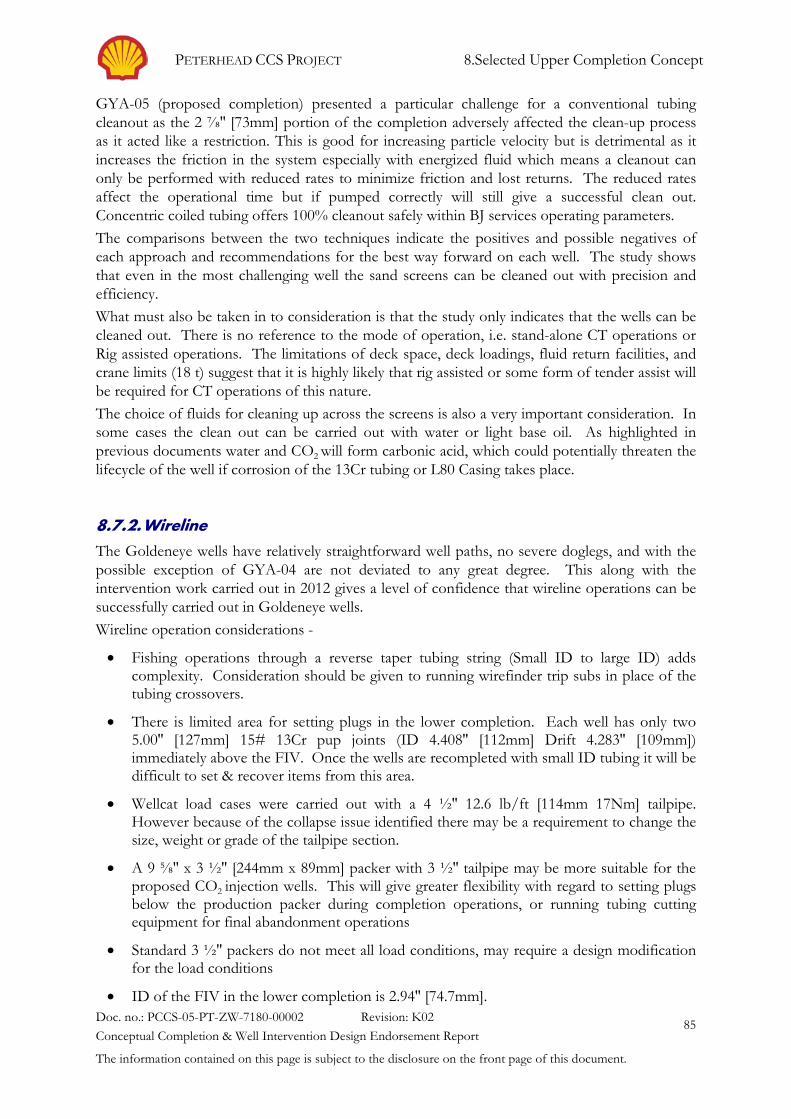
PETERHEAD CCS PROJECT 8.Selected Upper Completion Concept
Doc. no.: PCCS-05-PT-ZW-7180-00002 Revision: K02 Conceptual Completion & Well Intervention Design Endorsement Report
The information contained on this page is subject to the disclosure on the front page of this document.
85
GYA-05 (proposed completion) presented a particular challenge for a conventional tubing cleanout as the 2 ⅞'' [73mm] portion of the completion adversely affected the clean-up process as it acted like a restriction. This is good for increasing particle velocity but is detrimental as it increases the friction in the system especially with energized fluid which means a cleanout can only be performed with reduced rates to minimize friction and lost returns. The reduced rates affect the operational time but if pumped correctly will still give a successful clean out. Concentric coiled tubing offers 100% cleanout safely within BJ services operating parameters. The comparisons between the two techniques indicate the positives and possible negatives of each approach and recommendations for the best way forward on each well. The study shows that even in the most challenging well the sand screens can be cleaned out with precision and efficiency. What must also be taken in to consideration is that the study only indicates that the wells can be cleaned out. There is no reference to the mode of operation, i.e. stand-alone CT operations or Rig assisted operations. The limitations of deck space, deck loadings, fluid return facilities, and crane limits (18 t) suggest that it is highly likely that rig assisted or some form of tender assist will be required for CT operations of this nature. The choice of fluids for cleaning up across the screens is also a very important consideration. In some cases the clean out can be carried out with water or light base oil. As highlighted in previous documents water and CO2 will form carbonic acid, which could potentially threaten the lifecycle of the well if corrosion of the 13Cr tubing or L80 Casing takes place.
8.7.2. Wireline The Goldeneye wells have relatively straightforward well paths, no severe doglegs, and with the possible exception of GYA-04 are not deviated to any great degree. This along with the intervention work carried out in 2012 gives a level of confidence that wireline operations can be successfully carried out in Goldeneye wells. Wireline operation considerations -
• Fishing operations through a reverse taper tubing string (Small ID to large ID) adds complexity. Consideration should be given to running wirefinder trip subs in place of the tubing crossovers.
• There is limited area for setting plugs in the lower completion. Each well has only two 5.00'' [127mm] 15# 13Cr pup joints (ID 4.408'' [112mm] Drift 4.283'' [109mm]) immediately above the FIV. Once the wells are recompleted with small ID tubing it will be difficult to set & recover items from this area.
• Wellcat load cases were carried out with a 4 ½'' 12.6 lb/ft [114mm 17Nm] tailpipe. However because of the collapse issue identified there may be a requirement to change the size, weight or grade of the tailpipe section.
• A 9 ⅝'' x 3 ½'' [244mm x 89mm] packer with 3 ½'' tailpipe may be more suitable for the proposed CO2 injection wells. This will give greater flexibility with regard to setting plugs below the production packer during completion operations, or running tubing cutting equipment for final abandonment operations
• Standard 3 ½'' packers do not meet all load conditions, may require a design modification for the load conditions
• ID of the FIV in the lower completion is 2.94'' [74.7mm].

PETERHEAD CCS PROJECT 8.Selected Upper Completion Concept
Doc. no.: PCCS-05-PT-ZW-7180-00002 Revision: K02 Conceptual Completion & Well Intervention Design Endorsement Report
The information contained on this page is subject to the disclosure on the front page of this document.
86
• Qualification of equipment in CO2 environment for post injection well intervention, prevention and mitigation against effects such as JT cooling and ED

PETERHEAD CCS PROJECT 9.References
Doc. no.: PCCS-05-PT-ZW-7180-00002 Revision: K02 Conceptual Completion & Well Intervention Design Endorsement Report
The information contained on this page is subject to the disclosure on the front page of this document.
87
9. References
1. PCCS-05-PT-ZW-7180-00005 Well Functional Specification, Peterhead Goldeneye CCS, 2014, Key Knowledge Deliverable 11.098.
2. PCCS-05-PT-ZW-7180-00003 Peterhead Goldeneye CCS – Well Completion Concept
Select Report, 2014 Key Knowledge Deliverable 11.097
3. UKCCS-KT-S7.17-Shell-002-Completion Concept Select, Goldeneye CCS, 2011
4. UKCCS-KT-S7.16-Shell-001-Material Selection Report, 2011
5. UKCCS-KT-S7.16-Shell-007 Cement Concept Select, Goldeneye CCS, 2010
6. PCCS-05-PT-ZW-7180-00001 Abandonment Concept for Injection Wells, Peterhead Goldeneye CCS, 2014, Key Knowledge Deliverable 11.000
7. Oil & Gas UK, “Guidelines for the Suspension and Abandonment of Wells”, January
2009
8. Well Integrity for CO2 storage in the fields Barendrecht and Barendrecht-Ziedewij – TNO – June 2007
9. - PCCS-05-PT-ZW-7180-00004 Well Integrity Assessment Report, Peterhead
Goldeneye CCS, 2014, Key Knowledge Delivarable 11.113

PETERHEAD CCS PROJECT 10.Appendices
Doc. no.: PCCS-05-PT-ZW-7180-00002 Revision: K02 Conceptual Completion & Well Intervention Design Endorsement Report
The information contained on this page is subject to the disclosure on the front page of this document.
88
10. Appendices
APPENDIX 1. Goldeneye Wells The Goldeneye field consists of a normally unmanned platform with five gas production wells. Well DTI 14/29a-A4Z (GYA02S1) is the sidetrack of DTI 14/29a-A4 (GYA02). The wells are all very similar in design and were drilled with a jack-up rig during 2003/2004:
- 30'' [762mm] Conductor driven to ~750’ [229m] (by barge). Trepanned at seabed level. - 20'' x 13 ⅜'' [508 x 340mm] to ~4000’ [1219m] (x/o @ ~700’ [213m]) - 10 ¾'' x 9 ⅝'' [273 x 245mm] production casing (x/o ~3100’ [945m]) of L80 steel - 7'' [178mm] slotted liner with screens and gravel pack - 7'', 13Cr upper completion - 9 ⅝'' production packer with perforated joint below - PBR above the production packer - Permanent Downhole gauge - TRSSSV at around 2500’ [762m] - Christmas tree 6 ⅜'' [162mm] mono-bore, 5000 psia [345bar], Cameron - Wellhead, Cameron SSMC compact design
All Goldeneye production wells are deviated wells with the following details:
Table 10-1: Goldeneye wells directional data [1ft = 0.3048m]
GYA-01 GYA-02s1 GYA-03 GYA-04 GYA-05
Max. Inclination
30.4° @ 7574’
60.5° @ 10622’
40.1° @ 5983’
68.1° @ 6020’
7.2° @ 1785’
Total Depth 9166’ 11464’ 9507’ 13262’ 8535’

PETERHEAD CCS PROJECT 10.Appendices
Doc. no.: PCCS-05-PT-ZW-7180-00002 Revision: K02 Conceptual Completion & Well Intervention Design Endorsement Report
The information contained on this page is subject to the disclosure on the front page of this document.
89
Table 10-2: GYA01 (14/29a-A3) [1’’ = 25.4mm, 1ft = 0.3048m, 1psi=68.95mbar]
Surface location UTM Lat/Lon
N 6,429,207.70 m E 477,554.30 m
58 deg. 00 min. 9.323 sec. N 00 deg. 22 min. 47.073 sec. W
Formation pressures Initial: 3800 psia (8265’ TVSS)
Current : 2150 psia Abandonment : 3800
psia
No MDT/RFT’s taken on the production wells
Total depth (8 ½” OH) 9166’ AHD (RKB) Reservoir T = ~180°F (TD)
Water depth 395’ Cameron SSMC wellhead A: 460 inhib
Derrick Floor elevation 152.5’ Tree:Cameron 6 3/8” monobore 5k
B: 560 OBM
Maximum Inclination 30.4 degrees at 7574’ A-annulus 460 pptf inhib. seawater
C: Seawater
30” conductor 749.8’ AHD (RKB) 1.5” WT - X52 – Merlin (Int Upset)
2” WT used for drive shoe
20” x 13 3/8” casing 4155’ AHD (RKB) 20”: 202.7# - X80 – Merlin (top jt)
20”: 202.7# - X65 – Merlin top/
SR20 bottom (2nd joint) 20”: 202.7# - X65 – SR20, all
1”WT 13 3/8”: 68# - L80 – Dino
VAM x/o at 704’
675 (EMW 630)
10 ¾” x 9 5/8” casing 9006’ AHD (RKB) 10 ¾”: 55.5# - L80 - VAM Top 9 5/8”: 53.5# - L80 - VAM Top
x/o at 3130’
N.A
7” Liner (pre-drilled) 9163’ AHD (RKB) 29.0# -13CrL80 – NK3SB
Cement Details
30” cement job: N/A Driven (Heerema barge) 20” x 13 3/8” cement job:
Single 582 pptf, X-Lite 6 - 7 bpm. Stinger cementation 707 bbl Final diff. pressure 200 psia
Pressure test 2400 psia Returns observed at seabed by ROV (after 680 bbl)
10 ¾” x 9 5/8” cement job:

PETERHEAD CCS PROJECT 10.Appendices
Doc. no.: PCCS-05-PT-ZW-7180-00002 Revision: K02 Conceptual Completion & Well Intervention Design Endorsement Report
The information contained on this page is subject to the disclosure on the front page of this document.
90
Single 728 pptf, Class G 8.5 bpm, plugs bumped
TTOC 7506’ Centralisers: (Weatherford TR3) 113 bbl
Final diff. pressure 1460 psia No losses
Pressure test 4500 psia
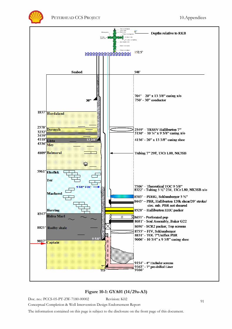
PETERHEAD CCS PROJECT 10.Appendices
Doc. no.: PCCS-05-PT-ZW-7180-00002 Revision: K02 Conceptual Completion & Well Intervention Design Endorsement Report
The information contained on this page is subject to the disclosure on the front page of this document.
91
Figure 10-1: GYA01 (14/29a-A3)

PETERHEAD CCS PROJECT 10.Appendices
Doc. no.: PCCS-05-PT-ZW-7180-00002 Revision: K02 Conceptual Completion & Well Intervention Design Endorsement Report
The information contained on this page is subject to the disclosure on the front page of this document.
92
Table 10-3: GYA02s1 (14/29a-A4z) Surface location UTM Lat/Lon
N 6,429,207.60 m E 477,558.00 m
58 deg. 00 min. 9.321 sec. N 00 deg. 22 min. 46.848 sec. W
Formation pressures Initial: 3811 psia (8289’ TVSS)
Current: 2150 psia Abandonment: 3800
psia
No MDT’RFT taken
Total depth (8 ½” OH) 11464’ AHD (RKB) Reservoir T = ~182°F (TD)
Water depth 395’ Cameron SSMC wellhead A: 550 inhib
Derrick Floor elevation 152.5’ Tree:Cameron 6 3/8” monobore 5k
B: 610 OBM
Maximum Inclination 60.5 degrees at 10622’ A-annulus 460 pptf inhib. seawater
C: Seawater
30” conductor 749.8’ AHD (RKB); 2 x 6” holes cut 10’ above
seabed
1.5” WT - X52 – Merlin (Int Upset)
2” WT used for drive shoe
20” x 13 3/8” casing 4154.6’ AHD (RKB) 20”: 202.7# - X80 – Merlin (top jt)
20”: 202.7# - X65 – Merlin top/
SR20 bottom (2nd joint) 20”: 202.7# - X65 – SR20, all
1”WT 13 3/8”: 68# - L80 – Dino
VAM x/o at 703’
679 (EMW 631)
10 ¾” x 9 5/8” casing 11268’ AHD (RKB) window at 10990’ for
S/T
10 ¾”: 55.5# - L80 - VAM Top 9 5/8”: 53.5# - L80 - VAM Top
x/o at 3155’
N.A
7” Liner (pre-drilled) 11462’ AHD (RKB) 29.0# - 13 CrL80 – NK3SB
Cement Details
30” cement job: N/A Driven (Heerema barge)
20” x 13 3/8” cement job:
Single 582 pptf, X-Lite 7 bpm. Stinger cementation 775 bbl
No losses
Final diff. pressure 230 psia Returns observed at seabed by ROV (after 638 bbl)

PETERHEAD CCS PROJECT 10.Appendices
Doc. no.: PCCS-05-PT-ZW-7180-00002 Revision: K02 Conceptual Completion & Well Intervention Design Endorsement Report
The information contained on this page is subject to the disclosure on the front page of this document.
93
10 ¾” x 9 5/8” cement job:
Single 728 pptf, Class G 13 bpm, plugs bumped
TTOC 9768’ 10 Centralisers: Weatherford TR3
115 bbl
Final diff. pressure 1600 psia No losses
Pressure test 4500 psia

PETERHEAD CCS PROJECT 10.Appendices
Doc. no.: PCCS-05-PT-ZW-7180-00002 Revision: K02 Conceptual Completion & Well Intervention Design Endorsement Report
The information contained on this page is subject to the disclosure on the front page of this document.
94
Figure 10-2: GYA02s1

PETERHEAD CCS PROJECT 10.Appendices
Doc. no.: PCCS-05-PT-ZW-7180-00002 Revision: K02 Conceptual Completion & Well Intervention Design Endorsement Report
The information contained on this page is subject to the disclosure on the front page of this document.
95
Table 10-4: GYA03 (14/29a-A5)
Surface location UTM Lat/Lon
N 6,429,204.91 m E 477,554.30 m
58 deg. 00 min. 9.233 sec. N 00 deg. 22 min. 47.072 sec. W
Formation pressures Initial:~3820 psia (8387’TVSS)
Current: ~2150 psia Abandonment: ~3800
psia
No MDT’RFT taken
Total depth (8 ½” OH) 9507’ AHD (RKB) Reservoir T = ~182°F (TD)
Water depth 395’ Cameron SSMC wellhead A: 550 inhib
Derrick Floor elevation 152.5’ Tree:Cameron 6 3/8” monobore 5k
B: 610 OBM
Maximum Inclination 40.1 degrees at 5983’ A-annulus 460 pptf inhib. seawater
C: Seawater
30” conductor 738’ AHD (RKB); 2 x 6” holes cut 10’ above
seabed
1.5” WT - X52 – Merlin (Int Upset)
2” WT used for drive shoe
20” x 13 3/8” casing 4143’ AHD (RKB) 20”: 202.7# - X80 – Merlin (top jt)
20”: 202.7# - X65 – Merlin top/
SR20 bottom (2nd joint) 20”: 202.7# - X65 – SR20, all
1”WT 13 3/8”: 68# - L80 – Dino
VAM x/o at 703’
685 (EMW 630)
10 ¾” x 9 5/8” casing 9365’ AHD (RKB) 10 ¾”: 55.5# - L80 - VAM Top 9 5/8”: 53.5# - L80 - VAM Top
x/o at 3013’
N.A
7” Liner (pre-drilled) 9503’ AHD (RKB) 29.0# - 13 CrL80 – NK3SB
Cement Details
30” cement job: N/A Driven (Heerema barge)
20” x 13 3/8” cement job:
Single 572 pptf, X-Lite 8 bpm. Stinger cementation 653 bbl
6 bbl/hr losses before job
Final diff. pressure 300 psia Returns observed at seabed by ROV (after 627 bbl)

PETERHEAD CCS PROJECT 10.Appendices
Doc. no.: PCCS-05-PT-ZW-7180-00002 Revision: K02 Conceptual Completion & Well Intervention Design Endorsement Report
The information contained on this page is subject to the disclosure on the front page of this document.
96
10 ¾” x 9 5/8” cement job:
Single 728 pptf, Class G 8 bpm, plugs bumped
TTOC 7865’ 10 Centralisers: Weatherford TR3
115 bbl
Final diff. pressure 1320 psia No losses
Pressure test 4500 psia

PETERHEAD CCS PROJECT 10.Appendices
Doc. no.: PCCS-05-PT-ZW-7180-00002 Revision: K02 Conceptual Completion & Well Intervention Design Endorsement Report
The information contained on this page is subject to the disclosure on the front page of this document.
97
Figure 10-3: GYA03 (14/29a-A5)

PETERHEAD CCS PROJECT 10.Appendices
Doc. no.: PCCS-05-PT-ZW-7180-00002 Revision: K02 Conceptual Completion & Well Intervention Design Endorsement Report
The information contained on this page is subject to the disclosure on the front page of this document.
98
Table 10-5: GYA04 (14/29a-A1) Goldeneye Well GYA04 (14/29a-A1)
Surface location UTM Lat/Lon
N 6,429,205.1 m E 477,558.4 m
58 deg. 00 min. 9.230 sec. N 00 deg. 22 min. 46.847 sec. W
Formation pressures Initial:~3820 psia (8348’TVSS)
Current: ~2150 psia Abandonment: ~3800
psia
No MDT’RFT taken
Total depth (8 ½” OH) 13262’ AHD (RKB) Reservoir T = ~182°F (TD)
Water depth 395’ Cameron SSMC wellhead A: 550 inhib
Derrick Floor elevation 152.5’ Tree:Cameron 6 3/8” monobore 5k
B: 580 OBM
Maximum Inclination 68.1 degrees at 6020’ A-annulus 460 pptf inhib. seawater
C: Seawater
30” conductor 750’ AHD (RKB); 2 x 6” holes cut 10’ above
seabed
1.5” WT - X52 – Merlin (Int Upset)
2” WT used for drive shoe
20” x 13 3/8” casing 4224’ AHD (RKB) 20”: 202.7# - X80 – Merlin (top jt)
20”: 202.7# - X65 – Merlin top/
SR20 bottom (2nd joint) 20”: 202.7# - X65 – SR20, all
1”WT 13 3/8”: 68# - L80 – Dino
VAM x/o at 705’
688 (EMW 633)
10 ¾” x 9 5/8” casing 13010’ AHD (RKB) 10 ¾”: 55.5# - L80 - VAM Top 9 5/8”: 53.5# - L80 - VAM Top
x/o at 2768’
N.A
7” Liner (pre-drilled) 13255’ AHD (RKB) 29.0# - 13 CrL80 – NK3SB
Cement Details
30” cement job: N/A Driven (Heerema barge)
20” x 13 3/8” cement job:
Single 572 pptf, X-Lite 8 bpm. Stinger cementation 1450 bbl
Pressure test 2400 psia 44 Centralisers: (Econolisers)
Returns observed at 4225’ – 4136’: 1 per jt

PETERHEAD CCS PROJECT 10.Appendices
Doc. no.: PCCS-05-PT-ZW-7180-00002 Revision: K02 Conceptual Completion & Well Intervention Design Endorsement Report
The information contained on this page is subject to the disclosure on the front page of this document.
99
seabed by ROV (after 1400 bbl)
4136’ – 725’: 1 per 2 jts
10 ¾” x 9 5/8” cement job:
Single 728 pptf, Class G 6 bpm, plugs bumped
Final diff. pressure 1500 psia 24 bbl losses during cementation
Pressure test 4500 si

PETERHEAD CCS PROJECT 10.Appendices
Doc. no.: PCCS-05-PT-ZW-7180-00002 Revision: K02 Conceptual Completion & Well Intervention Design Endorsement Report
The information contained on this page is subject to the disclosure on the front page of this document.
100
Figure 10-4: GYA04 (14/29a-A1)
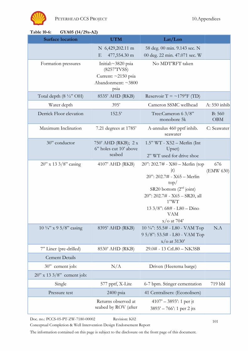
PETERHEAD CCS PROJECT 10.Appendices
Doc. no.: PCCS-05-PT-ZW-7180-00002 Revision: K02 Conceptual Completion & Well Intervention Design Endorsement Report
The information contained on this page is subject to the disclosure on the front page of this document.
101
Table 10-6: GYA05 (14/29a-A2) Surface location UTM Lat/Lon
N 6,429,202.11 m E 477,554.30 m
58 deg. 00 min. 9.143 sec. N 00 deg. 22 min. 47.071 sec. W
Formation pressures Initial:~3820 psia (8257’TVSS)
Current: ~2150 psia Abandonment: ~3800
psia
No MDT’RFT taken
Total depth (8 ½” OH) 8535’ AHD (RKB) Reservoir T = ~179°F (TD)
Water depth 395’ Cameron SSMC wellhead A: 550 inhib
Derrick Floor elevation 152.5’ Tree:Cameron 6 3/8” monobore 5k
B: 560 OBM
Maximum Inclination 7.21 degrees at 1785’ A-annulus 460 pptf inhib. seawater
C: Seawater
30” conductor 750’ AHD (RKB); 2 x 6” holes cut 10’ above
seabed
1.5” WT - X52 – Merlin (Int Upset)
2” WT used for drive shoe
20” x 13 3/8” casing 4107’ AHD (RKB) 20”: 202.7# - X80 – Merlin (top jt)
20”: 202.7# - X65 – Merlin top/
SR20 bottom (2nd joint) 20”: 202.7# - X65 – SR20, all
1”WT 13 3/8”: 68# - L80 – Dino
VAM x/o at 704’
676 (EMW 630)
10 ¾” x 9 5/8” casing 8395’ AHD (RKB) 10 ¾”: 55.5# - L80 - VAM Top 9 5/8”: 53.5# - L80 - VAM Top
x/o at 3130’
N.A
7” Liner (pre-drilled) 8530’ AHD (RKB) 29.0# - 13 CrL80 – NK3SB
Cement Details
30” cement job: N/A Driven (Heerema barge)
20” x 13 3/8” cement job:
Single 577 pptf, X-Lite 6-7 bpm. Stinger cementation 719 bbl
Pressure test 2400 psia 41 Centralisers: (Econolisers)
Returns observed at seabed by ROV (after
4107’ – 3893’: 1 per jt 3893’ – 766’: 1 per 2 jts

PETERHEAD CCS PROJECT 10.Appendices
Doc. no.: PCCS-05-PT-ZW-7180-00002 Revision: K02 Conceptual Completion & Well Intervention Design Endorsement Report
The information contained on this page is subject to the disclosure on the front page of this document.
102
520 bbl)
10 ¾” x 9 5/8” cement job:
Single 728 pptf, Class G 9 bpm, plugs bumped
Final diff. pressure 1200 psia No losses during cementation
Pressure test 4500 psia 80 bbl 676 pptf spacer

PETERHEAD CCS PROJECT 10.Appendices
Doc. no.: PCCS-05-PT-ZW-7180-00002 Revision: K02 Conceptual Completion & Well Intervention Design Endorsement Report
The information contained on this page is subject to the disclosure on the front page of this document.
103
Figure 10-5: GYA05 (14/29a-A2)

PETERHEAD CCS PROJECT 10.Appendices
Doc. no.: PCCS-05-PT-ZW-7180-00002 Revision: K02 Conceptual Completion & Well Intervention Design Endorsement Report
The information contained on this page is subject to the disclosure on the front page of this document.
104
APPENDIX 2. WellCat Output Graphs
A2.1. Goldeneye Conductor and Surface Casing Assumptions 1 Worst case corrosive wall loss has been assumed - 0.5mm/yr over a 25 yr period 2 A typical tidal range of 10ft [3m] from HAT to LAT assumed 3 A pipe with a reduced OD equivalent to 25mm (12.5mm wall loss) has been modelled over
the 10ft tidal range
A2.2. Results 1 Due to the heavy wall one inch thickness - ~25mm section of the 20'' [508mm] surface
casing, a 12.5mm wall loss due to corrosion leaves the pipe within limits during the high compression condition of the CO2 injection.
2 A minimum axial compressive SF of 2.42 (abs) is seen at the base of the corroded section modelled.
Below are the WellCat outputs for the Goldeneye Platform

PETERHEAD CCS PROJECT 10.Appendices
Doc. no.: PCCS-05-PT-ZW-7180-00002 Revision: K02 Conceptual Completion & Well Intervention Design Endorsement Report
The information contained on this page is subject to the disclosure on the front page of this document.
105
Figure 10-6: Goldeneye Casing and Tubing Configuration

PETERHEAD CCS PROJECT 10.Appendices
Doc. no.: PCCS-05-PT-ZW-7180-00002 Revision: K02 Conceptual Completion & Well Intervention Design Endorsement Report
The information contained on this page is subject to the disclosure on the front page of this document.
106
Figure 10-7: Cumulative 20'' Surface Casing Loads
20" x 13 3/8" Surface Casing delta 10 3/4" x 9 5/8" Production Casing delta 7" Production Liner Install Wellhead - 20in x 13 3/8" Surface Casing -8819 NA NANipple-Up BOP - 20in x 13 3/8" Surface Casing -41888 -33069 NA NA
Primary Cementing - 10 3/4in x 9 5/8" Production Casing -323275 -281387 281387 NAPrimary Cementing - 5 1/2in x 3 1/2" Production Tubing -399909 -76634 267552 -13835 -38165
Nipple-down BOP - 5 1/2in x 3 1/2" Production Tubing -367331 32578 267965 413 -38165Nipple-Up Tree - 5 1/2in x 3 1/2" Production Tubing -412940 -45609 267387 -578 -38165
p15 worst case inj (0.1C 115Bar 50Mscf) - 5 1/2in x 3 1/2" Production Tu -621732 -208792 423668 156281 162503
LoadAxial Load (lbf)
New surface load in production casing

PETERHEAD CCS PROJECT 10.Appendices
Doc. no.: PCCS-05-PT-ZW-7180-00002 Revision: K02 Conceptual Completion & Well Intervention Design Endorsement Report
The information contained on this page is subject to the disclosure on the front page of this document.
107
Figure 10-8: 20'' Section von Mises Plot with 12.5 mm Corrosion Loss
DLP - Section 2 of surface casing with 0.5mm/yr wall loss assumed (25yrs)
Design Limits - 13 3/8" Surf ace Casing Section 2 - OD 19.016 in - Weight 100.509 ppf - Grade X-80 25mm ext wall loss
-2700000 -2400000 -2100000 -1800000 -1500000 -1200000 -900000 -600000 -300000 0 300000 600000 900000 1200000 1500000 1800000 2100000 2400000 2700000 3000000
6000
5500
5000
4500
4000
3500
3000
2500
2000
1500
1000
500
0
-500
-1000
-1500
-2000
-2500
-3000
-3500
-4000
-4500
Ef f ectiv e Tension (lbf )
Eff
ectiv
e In
tern
al P
ress
ure
(psi
)
Burst 1.100
Collapse 1.000
Tension 1.300
Triaxial 1.100
Compression 1.150
Note: Limits are approximate
SC.7 WC inj (p15) orig/origSC.8 WC inj (p15) orig/det

PETERHEAD CCS PROJECT 10.Appendices
Doc. no.: PCCS-05-PT-ZW-7180-00002 Revision: K02 Conceptual Completion & Well Intervention Design Endorsement Report
The information contained on this page is subject to the disclosure on the front page of this document.
108
Figure 10-9: 20'' Safety Factor after 12.5 mm Corrosion
Axial SF's - Section 2 of surface casing with 0.5mm/yr wall loss assumed (25yrs)
Axial Saf ety Factor - 13 3/8" Surf ace Casing
0.000 0.263 0.526 0.789 1.053 1.316 1.579 1.842 2.105 2.368 2.632 2.895 3.158 3.421 3.684 3.947 4.211 4.474 4.737 5.000
0
200
400
600
800
1000
1200
1400
1600
1800
2000
2200
2400
2600
2800
3000
3200
3400
3600
3800
4000
4200
Absolute Axial Saf ety Factor
MD
(ft
)
SC.7 WC inj (p15) orig/origSC.8 WC inj (p15) orig/detAxial Design Factor = 1.150, 1.300
Corroded section -12.5mm external wall
loss

PETERHEAD CCS PROJECT
Doc. no.: PCCS-05-PT-ZW-7180-00002 Revision: K02 Conceptual Completion & Well Intervention Design Endorsement Report
The information contained on this page is subject to the disclosure on the front page of this document.
103
APPENDIX 3. Casing Design for CO2 Injection
A3.1. Casing Design Assumptions 1 10 % drill through wear has been simulated on both the 20'' x 13 3/8'' [508mm x 340mm]
surface casing and the 10 ¾'' x 9 ⅝'' [273mm x 245mm] production casing. (10% is the standard default value to allow for casing affected by mechanical abrasion - drilling through casing).
2 A number of sensitivities have been carried out with respect to CO2 injection rates with the design rate being 50 MMscf/day at 115 bara wellhead pressure with a wellhead inlet temperature of 0.1°C.
3 Full drilling thermal based on the original well build has been simulated to accurately assess the casing initial conditions
4 A fixed wellhead approach has been taken for the initial casing analysis and will be revised once a wellhead movement analysis has been performed
5 When performed the surface load analysis will include the substantial corrosion seen in the surface casing
6 A single section 3 ½'' [89mm] tubing string has been used in the design with base oil packer fluid
7 The predrilled liner for the gravel-pack has not been analysed
A3.2. Results The load cases are listed in A3.5 and in A3.6 with the corresponding safety factors. The loads are also shown graphically and listed in the graph 'legend box'.
Surface casing loads give low safety factors in the early days of CO2 injection into the well. Safety factor values are 2.4 SF for axial loads and 3.2 SF for triaxial loads. For the production casing, the tubing leak near surface and the casing evacuation cases result in the smallest safety factors. 1 Both the surface casing and the production casing are within limits for the loads modelled
with the minimum safety factors listed in the following tables 2 The driving load cases exist in Q1 & Q4 of the design limits plots indicating the tensile
loading due to thermal contraction.

PETERHEAD CCS PROJECT
Doc. no.: PCCS-05-PT-ZW-7180-00002 Revision: K02 Conceptual Completion & Well Intervention Design Endorsement Report
The information contained on this page is subject to the disclosure on the front page of this document.
104
A3.3. Surface Casing Loads
20" section - surface casing
Design Limits - 13 3/8" Surf ace Casing Section 1 - OD 20.000 in - Weight 202.700 ppf - Grade X-80 10% wear
-5250000 -4500000 -3750000 -3000000 -2250000 -1500000 -750000 0 750000 1500000 2250000 3000000 3750000 4500000 5250000 6000000 6750000 7500000 8250000 9000000
12000
11000
10000
9000
8000
7000
6000
5000
4000
3000
2000
1000
0
-1000
-2000
-3000
-4000
-5000
-6000
-7000
-8000
Ef f ectiv e Tension (lbf )
Eff
ectiv
e In
tern
al P
ress
ure
(psi
)
Burst 1.100
Collapse 1.000
Tension 1.300
Triaxial 1.100
Compression 1.150
Connection Burst 1.100
Connection Tension 1.300Connection Compression 1.150
Note: Limits are approximate
Initial ConditionsSC.1 Early CO2 inj (-25F 50Mscf )orig/detSC.2 Late CO2 inj (37F 60Mscf )orig/detSC.3 Early CO2 inj (37F 40Mscf )orig/detSC.4 Early CO2 inj (37F 54Mscf )orig/detSC.5 Mid CO2 inj (37F 32Mscf )orig/detSC.6 Mid CO2 inj (37F 48Mscf )orig/detSC.7 WC inj (p15) orig/origSC.8 WC inj (p15) orig/det
13 3/8" section - surface casing
Design Limits - 13 3/8" Surf ace Casing Section 2 - OD 13.375 in - Weight 68.000 ppf - Grade N-80 10% wear
-1800000 -1600000 -1400000 -1200000 -1000000 -800000 -600000 -400000 -200000 0 200000 400000 600000 800000 1000000 1200000 1400000 1600000 1800000 2000000
9000
8250
7500
6750
6000
5250
4500
3750
3000
2250
1500
750
0
-750
-1500
-2250
-3000
-3750
-4500
-5250
-6000
Ef f ectiv e Tension (lbf )
Eff
ectiv
e In
tern
al P
ress
ure
(psi
)
Burst 1.100
Collapse 1.000
Tension 1.300
Triaxial 1.100
Compression 1.150
Connection Compression 1.150
Note: Limits are approximate
Initial ConditionsSC.1 Early CO2 inj (-25F 50Mscf )orig/detSC.2 Late CO2 inj (37F 60Mscf )orig/detSC.3 Early CO2 inj (37F 40Mscf )orig/detSC.4 Early CO2 inj (37F 54Mscf )orig/detSC.5 Mid CO2 inj (37F 32Mscf )orig/detSC.6 Mid CO2 inj (37F 48Mscf )orig/detSC.7 WC inj (p15) orig/origSC.8 WC inj (p15) orig/det

PETERHEAD CCS PROJECT
Doc. no.: PCCS-05-PT-ZW-7180-00002 Revision: K02 Conceptual Completion & Well Intervention Design Endorsement Report
The information contained on this page is subject to the disclosure on the front page of this document.
105
A3.4. Production Casing Loads
10 3/4" section - production casing
Design Limits - 9 5/8" Production Casing Section 1 - OD 10.750 in - Weight 55.500 ppf - Grade L-80 10% wear
-1350000 -1200000 -1050000 -900000 -750000 -600000 -450000 -300000 -150000 0 150000 300000 450000 600000 750000 900000 1050000 1200000 1350000 1500000
7500
6750
6000
5250
4500
3750
3000
2250
1500
750
0
-750
-1500
-2250
-3000
-3750
-4500
-5250
-6000
-6750
-7500
Ef f ectiv e Tension (lbf )
Eff
ectiv
e In
tern
al P
ress
ure
(psi
)
Burst 1.100
Collapse 1.000
Tension 1.300
Triaxial 1.100
Compression 1.150
Connection Compression 1.150
Note: Limits are approximate
Initial ConditionsPC.1 Early CO2 inj (-25F 50Mscf )PC.2 Late CO2 inj (37F 60Mscf )PC.3 Early CO2 inj (37F 40Mscf )PC.4 Early CO2 inj (37F 54Mscf )PC.5 Mid CO2 inj (37F 32Mscf )PC.6 Mid CO2 inj (37F 48Mscf )PC.1 tubing leak detPC.2 tubing leak detPC.3 tubing leak detPC.4 tubing leak detPC.5 tubing leak detPC.6 tubing leak detPC.7 casing ev acPC.8 WC inj (0.1c 115Bar 50Mscf )PC.8 tubing leak detPC.9 Start of well killPC.10 End of well kill
9 5/8" section - production casing (above packer)
Design Limits - 9 5/8" Production Casing Section 2 - OD 9.625 in - Weight 53.500 ppf - Grade L-80 10% wear
-1350000 -1200000 -1050000 -900000 -750000 -600000 -450000 -300000 -150000 0 150000 300000 450000 600000 750000 900000 1050000 1200000 1350000 1500000
10000
9000
8000
7000
6000
5000
4000
3000
2000
1000
0
-1000
-2000
-3000
-4000
-5000
-6000
-7000
-8000
-9000
-10000
Ef f ectiv e Tension (lbf )
Eff
ectiv
e In
tern
al P
ress
ure
(psi
)
Burst 1.100
Collapse 1.000
Tension 1.300
Triaxial 1.100
Compression 1.150
Connection Compression 1.150
Note: Limits are approximate
Initial ConditionsPC.1 Early CO2 inj (-25F 50Mscf )PC.2 Late CO2 inj (37F 60Mscf )PC.3 Early CO2 inj (37F 40Mscf )PC.4 Early CO2 inj (37F 54Mscf )PC.5 Mid CO2 inj (37F 32Mscf )PC.6 Mid CO2 inj (37F 48Mscf )PC.1 tubing leak detPC.2 tubing leak detPC.3 tubing leak detPC.4 tubing leak detPC.5 tubing leak detPC.6 tubing leak detPC.7 casing ev acPC.8 WC inj (0.1c 115Bar 50Mscf )PC.8 tubing leak detPC.9 Start of well killPC.10 End of well kill

PETERHEAD CCS PROJECT
Doc. no.: PCCS-05-PT-ZW-7180-00002 Revision: K02 Conceptual Completion & Well Intervention Design Endorsement Report
The information contained on this page is subject to the disclosure on the front page of this document.
106
A3.5. Minimum Safety Factors - Surface Casing
TRIAXIAL SAFETY FACTOR
BURST SAFETY FACTOR
COLLAPSE SAFETY FACTOR
AXIAL SAFETY FACTOR
Initial Conditions 6.45 @ 754.6 ft 80.07 @ 539 ft 5.7 @ 4153.9 ft 5.47 @ 4153.9 ft (C)
SC.1 Early CO2 inj
(-25F 50Mscf)orig/det
3.19 @ 754.6 ft 6.35 @ 4153.9 ft --- 2.42 @ 702.9 ft (T)
SC.2 Late CO2 inj
(37F 60Mscf)orig/det
4.29 @ 754.6 ft 6.35 @ 4153.9 ft --- 3.42 @ 702.9 ft (T)
SC.3 Early CO2 inj
(37F 40Mscf)orig/det
4.31 @ 754.6 ft 6.35 @ 4153.9 ft --- 3.44 @ 702.9 ft (T)
SC.4 Early CO2 inj
(37F 54Mscf)orig/det
4.29 @ 754.6 ft 6.35 @ 4153.9 ft --- 3.42 @ 702.9 ft (T)
SC.5 Mid CO2 inj
(37F 32Mscf)orig/det
4.32 @ 754.6 ft 6.34 @ 4153.9 ft --- 3.45 @ 702.9 ft (T)
9 5/8" section - production casing (below packer)
Design Limits - 9 5/8" Production Casing Section 3 - OD 9.625 in - Weight 53.500 ppf - Grade L-80 10% wear
-1350000 -1200000 -1050000 -900000 -750000 -600000 -450000 -300000 -150000 0 150000 300000 450000 600000 750000 900000 1050000 1200000 1350000 1500000
10000
9000
8000
7000
6000
5000
4000
3000
2000
1000
0
-1000
-2000
-3000
-4000
-5000
-6000
-7000
-8000
-9000
-10000
Ef f ectiv e Tension (lbf )
Eff
ectiv
e In
tern
al P
ress
ure
(psi
)
Burst 1.100
Collapse 1.000
Tension 1.300
Triaxial 1.100
Compression 1.150
Connection Compression 1.150
Note: Limits are approximate
Initial ConditionsPC.1 Early CO2 inj (-25F 50Mscf )PC.2 Late CO2 inj (37F 60Mscf )PC.3 Early CO2 inj (37F 40Mscf )PC.4 Early CO2 inj (37F 54Mscf )PC.5 Mid CO2 inj (37F 32Mscf )PC.6 Mid CO2 inj (37F 48Mscf )PC.1 tubing leak detPC.2 tubing leak detPC.3 tubing leak detPC.4 tubing leak detPC.5 tubing leak detPC.6 tubing leak detPC.7 casing ev acPC.8 WC inj (0.1c 115Bar 50Mscf )PC.8 tubing leak detPC.9 Start of well killPC.10 End of well kill

PETERHEAD CCS PROJECT
Doc. no.: PCCS-05-PT-ZW-7180-00002 Revision: K02 Conceptual Completion & Well Intervention Design Endorsement Report
The information contained on this page is subject to the disclosure on the front page of this document.
107
SC.6 Mid CO2 inj
(37F 48Mscf)orig/det
4.3 @ 754.6 ft 6.35 @ 4153.9 ft --- 3.42 @ 702.9 ft (T)
SC.7 WC inj
(p15) orig/orig
4.09 @ 754.6 ft 6.35 @ 4153.9 ft --- 3.19 @ 702.9 ft (T)
SC.8 WC inj
(p15) orig/det
3.97 @ 754.6 ft --- 4.93 @ 4153.9 ft 3.29 @ 702.9 ft (T)
Triaxial Burst Collapse Axial
MINIMUM SAFETY FACTORS
3.19 6.34 4.93 2.42
Notes: 1ft = 0.3048m
These are all CO2 load cases - early, mid-term, and late injection cases. WC above is ''Worst Case'' - actually CO2 injection rates with the design rate being 50 MMscf/day at 115 bara wellhead pressure with a wellhead inlet temperature of 0.1°C. p15 refers to the thermal load case modelled in PROD.

PETERHEAD CCS PROJECT
Doc. no.: PCCS-05-PT-ZW-7180-00002 Revision: K02 Conceptual Completion & Well Intervention Design Endorsement Report
The information contained on this page is subject to the disclosure on the front page of this document.
108
A3.6. Minimum Safety Factors - Production Casing
TRIAXIAL SAFETY FACTOR
BURST SAFETY FACTOR
COLLAPSE SAFETY FACTOR
AXIAL SAFETY FACTOR
Initial Conditions 4.08 @ 754.6 ft --- 2.95 @ 10989.9 ft 3.29 @ 10891 ft (C)
PC.1 Early CO2 inj (-25F 50Mscf)
1.83 @ 4256.9 ft --- 2.32 @ 9767.9 ft 1.96 @ 754.6 ft (T)
PC.2 Late CO2 inj (37F 60Mscf)
2.3 @ 4256.9 ft --- 2.43 @ 9767.9 ft 2.51 @ 754.6 ft (T)
PC.3 Early CO2 inj (37F 40Mscf)
2.34 @ 4256.9 ft --- 2.43 @ 9767.9 ft 2.56 @ 754.6 ft (T)
PC.4 Early CO2 inj (37F 54Mscf)
2.3 @ 4256.9 ft --- 2.43 @ 9767.9 ft 2.51 @ 754.6 ft (T)
PC.5 Mid CO2 inj (37F 32Mscf)
2.36 @ 4256.9 ft --- 2.43 @ 9767.9 ft 2.58 @ 754.6 ft (T)
PC.6 Mid CO2 inj (37F 48Mscf)
2.32 @ 4256.9 ft --- 2.43 @ 9767.9 ft 2.53 @ 754.6 ft (T)
PC.1 tubing leak det 1.86 @ 754.6 ft 8.35 @ 80.1 ft 17.33 @ 10989.9 ft 1.73 @ 754.6 ft (T)
PC.2 tubing leak det 2.06 @ 754.6 ft 2.77 @ 80.1 ft --- 1.93 @ 754.6 ft (T)
PC.3 tubing leak det 2.36 @ 754.6 ft 10.9 @ 80.1 ft 11.98 @ 10989.9 ft 2.21 @ 754.6 ft (T)
PC.4 tubing leak det 2.3 @ 754.6 ft 5.06 @ 80.1 ft --- 2.07 @ 754.6 ft (T)
PC.5 tubing leak det 2.39 @ 754.6 ft 7.65 @ 80.1 ft 24.13 @ 10989.9 ft 2.19 @ 754.6 ft (T)
PC.6 tubing leak det 2.27 @ 754.6 ft 4.26 @ 80.1 ft --- 2.05 @ 754.6 ft (T)
PC.7 casing evac 1.42 @ 9767.9 ft --- 1.12 @ 9767.9 ft 2.91 @ 754.6 ft (T)
PC.8 WC inj (0.1c 115Bar 50Mscf)
2.26 @ 4256.9 ft --- 2.42 @ 9767.9 ft 2.46 @ 754.6 ft (T)
PC.8 tubing leak det 2.17 @ 754.6 ft 3.63 @ 80.1 ft --- 1.97 @ 754.6 ft (T)
PC.9 Start of well kill 2.27 @ 754.6 ft 13.89 @ 10989.9 ft 3.69 @ 10934 ft 2.32 @ 754.6 ft (T)
PC.10 End of well kill 2.28 @ 754.6 ft 13.92 @ 10989.9 ft 2.84 @ 10934 ft 2.34 @ 754.6 ft (T)
MINIMUM 1.42 2.77 1.12 1.73

PETERHEAD CCS PROJECT
Doc. no.: PCCS-05-PT-ZW-7180-00002 Revision: K02 Conceptual Completion & Well Intervention Design Endorsement Report
The information contained on this page is subject to the disclosure on the front page of this document.
109
SAFETY FACTORS
A3.7. Production Temperature Predictions
Figure 10-10: Goldeneye Tubing – Fluid Pressures
Fluid Temperature - Tubing/Workstring
-30 -15 0 15 30 45 60 75 90 105 120 135 150 165 180 195 210 225 240 255
0
750
1500
2250
3000
3750
4500
5250
6000
6750
7500
8250
9000
9750
10500
11250
12000
12750
13500
14250
15000
Temperature (°F)
MD
(ft
)
p2 Circulate to brinep3 Shut inp4 Grav el packp5 RIH comp to ref erence pointp6 RIH to TDp7 Displace tubing to base oilp8 Set packerp9 Early CO2 inj (-25F 50Mscf )p10 Late CO2 inj (37F 60Mscf )p11 Early CO2 inj (37F 40Mscf )p12 Early CO2 inj (37F 54Mscf )p13 Mid CO2 inj (37F 32Mscf )p14 Mid CO2 inj (37F 48Mscf )p15 worst case inj (0.1C 115Bar 50Mscf )p16 Shut in af ter p15p17 Start well killp18 end well killUndisturbed

PETERHEAD CCS PROJECT
Doc. no.: PCCS-05-PT-ZW-7180-00002 Revision: K02 Conceptual Completion & Well Intervention Design Endorsement Report
The information contained on this page is subject to the disclosure on the front page of this document.
110
A3.8. CO2 Injection Pressures
Figure 10-11: Goldeneye Tubing – Fluid Pressures
APPENDIX 4. SACROC Conclusions '' The Portland cement recovered from a 55-year old well with 30 years of CO2 exposure showed evidence of exposure to CO2 in the form of carbonate precipitate adjacent to the casing and heavily carbonated, orange-coloured cement adjacent to the shale cap rock. However, the structural integrity of the recovered cement core, petrographic observations, air permeameter data, and cement bond log indicate that the cement retained its capacity to prevent significant transport of fluid through the cement matrix. Observations and numerical calculations suggest that the CO2 producing the orange CO2 alteration originated by movement from the reservoir along the shale-cement interface. The CO2 producing a carbonate precipitate at the casing-cement interface may have originated by migration along the casing interface from the reservoir or from the interior of the well at casing joints or regions of casing corrosion. Numerical modelling shows that carbonation induced by diffusion of CO2 - saturated brine reproduces key features of the SACROC cement core. We used observations of the core to constrain the porosity, tortuosity, and reaction rates used in the modelling to values appropriate to well 49-6 at SACROC. Additional samples would be necessary to construct a more generally applicable model of CO2 -induced cement degradation. The observations demonstrate that Portland cement can retain its integrity at least over decades in a CO2 reservoir with conditions similar to SACROC. Numerical calculations are consistent with a slow rate of degradation by diffusive attack of CO2 that would allow a thick column of cement to survive for long periods of time. However, the observations also show that CO2 migrated along the casing-cement and shale-cement interfaces for some period of time. We were unable to quantify the amount of CO2 migration that may have
Fluid Pressure - Tubing/Workstring
0 355 711 1066 1421 1776 2132 2487 2842 3197 3553 3908 4263 4618 4974 5329 5684 6039 6395 6750
0
750
1500
2250
3000
3750
4500
5250
6000
6750
7500
8250
9000
9750
10500
11250
12000
12750
13500
14250
15000
Pressure (psi)
MD
(ft
)
p2 Circulate to brinep3 Shut inp4 Grav el packp5 RIH comp to ref erence pointp6 RIH to TDp7 Displace tubing to base oilp8 Set packerp9 Early CO2 inj (-25F 50Mscf )p10 Late CO2 inj (37F 60Mscf )p11 Early CO2 inj (37F 40Mscf )p12 Early CO2 inj (37F 54Mscf )p13 Mid CO2 inj (37F 32Mscf )p14 Mid CO2 inj (37F 48Mscf )p15 worst case inj (0.1C 115Bar 50Mscf )p16 Shut in af ter p15p17 Start well killp18 end well kill
PETERHEAD CCS PROJECT
Doc. no.: PCCS-05-PT-ZW-7180-00002 Revision: K02 Conceptual Completion & Well Intervention Design Endorsement Report
The information contained on this page is subject to the disclosure on the front page of this document.
111
occurred along these interfaces. The integrity of these interfaces appears to be the most critical issue in wellbore performance for CO2 sequestration. The cement core recovered at SACROC provides some help in understanding the experimental variability in studies of cement carbonation at reservoir conditions. The laboratory experiments of Duguid et al. (2005) investigated cement deterioration under conditions of flowing CO2 - saturated brine and they observed rapid degradation and loss of structural integrity within weeks of exposure. The SACROC sample clearly did not experience a similar flux of acidic brine. This indicates that for properly completed wells, the cement– cap rock interface does not experience flowing CO2 - saturated brine and the rapid cement decomposition observed by Duguid et al. (2005) is unlikely to occur. In contrast, the experiments of Barlet-Goue´dard et al. (2006) and Kutchko et al. (2006b) were conducted with a static volume of brine subject to high CO2 pressure. Barlet-Goue´dard et al.’s experiments were conducted at 90°C and 28 MPa, and they observed rapid penetration of CO2 and complete carbonation within 6 weeks. Their porosity and mechanical strength studies showed that the cement appears to retain significant hydrologic integrity but had clearly been substantially altered. Kutchko et al.’s experiments were conducted at 50°C and 30 MPa and showed very limited (slow) penetration of CO2 after 9 days (and after 3months as presented in Kutchko et al., 2006a). The SACROC cement samples (exposed to CO2 at 54°C and 18 MPa) showed rates of carbonation more compatible with the experiments of Kutchko et al., which may reflect the more similar temperatures of CO2 exposure. However, it also possible that the amount of CO2 exposure for the SACROC samples at 3 m above the reservoir contact was more limited. The time and conditions for cement curing times prior to CO2 exposure is another important variable: SACROC at 35 years (54°C) compared to Kutchko et al. at 28 days (22 and 50°C) and Barlet-Goue´dard et al. at 2 days (90°C). In any case, both the Barlet-Goue´dard et al. and Kutchko et al. Studies are consistent with cement retaining hydrologic integrity in a CO2 -rich environment, although the results of Barlet-Goue´dard et al. indicate that CO2 - induced cement degradation in higher temperature reservoirs may be of greater concern. The SACROC core in combination with the available experimental data allows some preliminary conclusions regarding wellbore integrity and CO2 storage. These studies indicate that Portland cement based wellbore systems, if properly completed, can prevent significant migration of CO2 from reservoirs for long periods of time (at least decades). A properly completed well need not be completely free of defects, but should not have continuous openings along either the cement-casing or cement–caprock interfaces that might permit a CO2 –brine mixture to flow that could dissolve cement and further widen the interface. The key variables appear to be the initial width and connectivity of the interfaces in addition to the pressure gradient driving flow from the reservoir. Future work to develop and strengthen these conclusions should include collecting additional core to understand whether the observations at well 49-6 are unique or typical at SACROC and to explore the significance of differing caprock and reservoir chemistries as well as differing operational histories. These studies could improve on our work by obtaining fluid samples to better constrain the geochemistry and collecting samples at multiple intervals to determine the maximum extent of carbonation. In addition, more experimental studies are needed to help interpret the field observations. These should focus on the evolution of cement-casing and cement–caprock interfaces as a function of initial interface width/quality and the CO2 - brine flux. Observations at SACROC suggest that under limited flux the interfaces may be self-sealing. Determining the conditions under which these interfaces become more transmissive with time remains a key unknown in evaluating the longevity of the Portland cement seal in wellbore systems ''.

PETERHEAD CCS PROJECT
Doc. no.: PCCS-05-PT-ZW-7180-00002 Revision: K02 Conceptual Completion & Well Intervention Design Endorsement Report
The information contained on this page is subject to the disclosure on the front page of this document.
112
PETERHEAD CCS PROJECT
Doc. no.: PCCS-05-PT-ZW-7180-00002 Revision: K02 Conceptual Completion & Well Intervention Design Endorsement Report
The information contained on this page is subject to the disclosure on the front page of this document.
113
APPENDIX 5. Cement Testing
A5.1. General From their literature, oil industry cementing companies claim their research and development has resulted in improved cement performance in CO2 wells. Qualifying these cements for use in CO2 wells would confirm or otherwise the cementing companies claims.
A5.2. Background Several laboratory studies have been carried out to investigate the effects of a CO2 plume on cement. Many of these have been carried out in the USA. The drivers for these studies are: - (American) Safe Drinking Water Act of 1974 - American legislation requires that wells within a certain distance of a CO2 injection site be
checked for existing wells and their condition - distance varies with State. In general, existing wells in the US are subdivided into three categories: - wells that are not plugged - wells plugged before 1952 and - those plugged after 1952 (when the American Petroleum Institute (API) standardized
plugging procedure and cement composition). The first two categories do not apply to Goldeneye and would be clearly unsatisfactory situation in any event. Fortunately, when the North Sea started up, initially it adopted API standards later improving and augmenting or replacing the standards. The result of American legislation and their greater availability of fields on land, for CO2 injection flood and for CO2 sequestration, has driven research. Eight classes of cement are listed in API Specification for Oilwell Cement i.e. Class A to H - the depth of well determines the difference. At one time B class cement was used in the North Sea together with class G cement. For most North Sea wells class G has been used. Research now includes all cement types. Since about 2005, there has been more research into CO2 and effects on cement, driven by sequestration. At the same time, oilfield cementing suppliers started to research and to devise CO2 resistant cements. These they have released and used them on CO2 projects around the World.
A5.3. Goldeneye Platform Conditions The distance CO2 has to be pumped by undersea pipeline depresses the injection temperatures compared to the American studies and is especially true for the Goldeneye application - distance from pipeline to shore is 105 km of subsea pipeline. Hence, injection temperature is expected to be in the order of zero to 5°C. In consequence testing of existing cement types will need to be carried out corresponding to Goldeneye temperatures and pressures. Generally, CO2 testing includes salinity testing. CO2 delivery is expected to be more or less free of water, hence this requirement may be relaxed.
A5.4. Cement Testing Outline To kick off testing, initially a statement of requirements will be required. From there a full time lab technician can put a procedure together in a couple of weeks. Very generally, the testing outline would be as follows:

PETERHEAD CCS PROJECT
Doc. no.: PCCS-05-PT-ZW-7180-00002 Revision: K02 Conceptual Completion & Well Intervention Design Endorsement Report
The information contained on this page is subject to the disclosure on the front page of this document.
114
- set up a ring bowl at reservoir temperature ~83°C and cure many cemented test pipes at temperature
- keep samples pressurised to reservoir pressure ~2,900 psia [200bar] with CO2. - then into cooler or temperature control to simulate downhole CO2 injection conditions - triaxial test and cut up samples at intervals - say every three months to see changes over time For CO2 resistant cements such as the high alumina and phosphate types, we know they do not react with CO2. Hence testing will confirm this lack of reaction but concentrate on the physical model.

PETERHEAD CCS PROJECT
Doc. no.: PCCS-05-PT-ZW-7180-00002 Revision: K02 Conceptual Completion & Well Intervention Design Endorsement Report
The information contained on this page is subject to the disclosure on the front page of this document.
115
APPENDIX 6. Original & Conceptual Completion Schematics
A6.1. Original Completion Diagram

PETERHEAD CCS PROJECT
Doc. no.: PCCS-05-PT-ZW-7180-00002 Revision: K02 Conceptual Completion & Well Intervention Design Endorsement Report
The information contained on this page is subject to the disclosure on the front page of this document.
116
A6.2. Dual Completion Concept

PETERHEAD CCS PROJECT
Doc. no.: PCCS-05-PT-ZW-7180-00002 Revision: K02 Conceptual Completion & Well Intervention Design Endorsement Report
The information contained on this page is subject to the disclosure on the front page of this document.
117
A6.3. Concentric completion Concept

PETERHEAD CCS PROJECT
Doc. no.: PCCS-05-PT-ZW-7180-00002 Revision: K02 Conceptual Completion & Well Intervention Design Endorsement Report
The information contained on this page is subject to the disclosure on the front page of this document.
118
A6.4. Insert String Concept

PETERHEAD CCS PROJECT
Doc. no.: PCCS-05-PT-ZW-7180-00002 Revision: K02 Conceptual Completion & Well Intervention Design Endorsement Report
The information contained on this page is subject to the disclosure on the front page of this document.
119
A6.5. Small Bore Completion Concept

PETERHEAD CCS PROJECT
Doc. no.: PCCS-05-PT-ZW-7180-00002 Revision: K02 Conceptual Completion & Well Intervention Design Endorsement Report
The information contained on this page is subject to the disclosure on the front page of this document.
120
A6.6. Downhole Choke Concept

PETERHEAD CCS PROJECT
Doc. no.: PCCS-05-PT-ZW-7180-00002 Revision: K02 Conceptual Completion & Well Intervention Design Endorsement Report
The information contained on this page is subject to the disclosure on the front page of this document.
121
11. Glossary of terms Term Definition
'' Inches
°C Degrees Celcius
°F Degrees Fahrenheit
13Cr 13 percent chrome content metallurgy
'A' annulus Annulus between the production tubing and production casing string AHD Along Hole Depth
ALARP As Low As Reasonably Practicable, and is a term often used in the environment of safety-critical and high-integrity systems. The ALARP principle is that the residual risk shall be as low as reasonably practicable
Annuli The space between adjacent strings of tubing or casing
'B' annulus Annulus between the production casing and intermediate casing string
bara Unit of pressure equal to 100,000 Pascals
Barrier Barriers prevent of mitigate the probability of each threat or prevent, limit the extent of, or provide immediate recovery from the Consequences
Base oil Oil with carcinogenic elements removed
BH Bottom Hole BHA Bottom Hole Assembly BHP Bottom Hole Pressure
BHP&T Bottom Hole Pressure and Temperature
Cap rock The shale layers above a reservoir that provide geological isolation to upward migration and provide the primary seal
CAPEX Capital Expenditure
CBL Cement Bond Logging
CCS Carbon Capture & Storage
Cement squeeze
Injection of cement to isolate a leak in the cement behind casing
CITHP Closed In Tubing Head Pressure
CL Control Line.
CO2 Carbon Dioxide
Completion The conduit for production or injection between the surface facilities and the reservoir. The upper completion comprises the tubing and

PETERHEAD CCS PROJECT
Doc. no.: PCCS-05-PT-ZW-7180-00002 Revision: K02 Conceptual Completion & Well Intervention Design Endorsement Report
The information contained on this page is subject to the disclosure on the front page of this document.
122
packer, etc. The reservoir completion is the screens, etc., across the reservoir interval.
CoP Cessation of Production
CTU Coil Tubing Unit
DAS Distributed Acoustic Sensing
DECC Department of Energy and Climate Change
DEP Shell Standards
DIANA Software package from TNO that solves, with the aid of FEM, problems relating to design and assessment activities in concrete, steel, soil, rock and soil-structure.
DTS Distributed Temperature Sensing
ED Explosive Decompression EMW Equivalent mud weight EOR Enhanced Oil Recovery
ESD Emergency Shut Down
FEED Front End Engineering Design
FEM Finite Element Modelling
FIT Formation integrity test
FIV Formation Isolation Valve
ft Feet
FWV Flow Wing Valve
H2CO3 Carbonic acid
Hazard The potential to cause harm, including ill health and injury, damage to property, products or the environment; production losses or increased liabilities. In this report: buoyant CO2
HAZID Hazard Identification Study
HAZOP Hazard and Operability Study
HNBR Hydrogenated Nitrile Butadiene Rubber
HSE Health, Safety and Environment IBHT Injection Bottom hole Temperature ICV Inflow Control Valve
ID Inside Diameter
Injection phase
The injection phase includes the period of site preparation for injection, the injection period itself and the period of well abandonment
JT Joules Thomson

PETERHEAD CCS PROJECT
Doc. no.: PCCS-05-PT-ZW-7180-00002 Revision: K02 Conceptual Completion & Well Intervention Design Endorsement Report
The information contained on this page is subject to the disclosure on the front page of this document.
123
km Kilometers (1000 meters)
kN Kilonewtons (1000 Newtons)
Leakage Migrated CO2 out of the containment that leaks into the biosphere (shallow subsurface and atmosphere). In contrast to seepage, leakage involves medium fluxes and medium concentrations
Leakage scenario
Group of threats that form cause-consequence relations leading to a certain route of migration and eventually leakage into the biosphere
LMGV Lower Master Gate Valve
LOT Leak-off Test
m Meters
mbar millibar
Mcf Thousand cubic feet at reservoir conditions
MD Measured depth
Migration Escaped CO2 out of the containment into the subsurface where it moves or trapped in other layers
mm millimeters (1/1000th of a meter)
MMscfd Million standard cubic feet per day
MMV Measurement, Monitoring and Verification
MOC Management of Change
MPS Multi-Pont Pressure Sensor
MSL Mean Sea Level
N Newtons, SI unit of force.
NUI Normally Unattended Installation OBM Oil based mud OD Outside Diameter
OLGA Modeling software
Open shoe An annulus that is open to a formation
OPEX Operational Expenditure
Packer A device that both anchors and seals the tubing to the production casing. The term production packer is still used even when the well is in injection mode
PBR Polished Bore Receptacle
PDG Permanent downhole gauge
PDG Pressure Gauge

PETERHEAD CCS PROJECT
Doc. no.: PCCS-05-PT-ZW-7180-00002 Revision: K02 Conceptual Completion & Well Intervention Design Endorsement Report
The information contained on this page is subject to the disclosure on the front page of this document.
124
PDGM Permanent Downhole Gauge Mandrel PEC Pulsed Eddy Current pH measure of the acidity or basicity of an aqueous solution
POOH Pull Out of Hole
PPB Parts per billion
ppmV Parts per million by Volume
Production casing
The casing providing the secondary wellbore barrier during production or injection (valid term even in injection mode)
PSIA Pounds per Square Inch
psia Pounds Per Square Inch
PVT Pressure, Volume, Temperature
Relief well A well constructed specifically to intersect the wellbore or reservoir of a blowing out well
SAS Stand Alone Screens
SCSSSV Surface Controlled Sub Surface Safety Valve
Seepage Migrated CO2 out of the containment that seeps into the biosphere (shallow subsurface and atmosphere). In contrast to leakage, seepage involves low fluxes and low concentrations
SSSV Subsurface Safety Valve
TD Total Depth
TDS Totally Dissolved Soilds
TNO Netherlands organization for applied scientific research
TOC Top of Cement
Top Event Incident that occurs when a hazard is realized, or the release of the hazard. The Top Event is typically some type of loss of control or release of energy. If this event can be prevented there can be no effect or consequence from the hazard
TRSSSV Tubing Retrievable Sub Surface safety Valve TVD Total Vertical Depth UCS Unconfined Compressive Strength
UGS Underground Gas Storage
UKCS United Kingdom Continental Shelf
UMGV Upper Master Gate Valve
Under ream
To mill out a section of casing / cement by the use of an expandable milling bit
USIT Ultrasonic Imaging Tool

PETERHEAD CCS PROJECT
Doc. no.: PCCS-05-PT-ZW-7180-00002 Revision: K02 Conceptual Completion & Well Intervention Design Endorsement Report
The information contained on this page is subject to the disclosure on the front page of this document.
125
VDL Variable Density Log
VSP Vertical Seismic Profile
WBM Water Based Mud
WEG Wireline Re-entry guide
WH Wellhead
WHP Wellhead Pressure
WITS Well Integrity Tests WTS Wirefinder Trip Sub XM Christmas Tree
XMtree Christmas Tree
XO Cross Over
UMV Upper Master Valve
Full Well Name Abbreviated Well Name
DTI 14/29a-A3 GYA01
DTI 14/29a-A4Z GYA02S1 (Sidetrack)
DTI 14/29a-A4 GYA02
DTI 14/29a-A5 GYA03
DTI 14/29a-A1 GYA04
DTI 14/29a-A2 GYA05
12. Glossary of Unit Conversions For the provision of the SI metric conversion factor as applicable to all imperial units in the Key Knowledge Deliverable.
Table 12-1: Unit Conversion Table
Function Unit - Imperial to SI Metric conversion Factor
Length 1 Foot = 0.3048m Metres 1 Inch = 2.54cm Centimetres 1 Inch = 25.4mm millimetres
Pressure 1 Psia = 0.0690 Bara
Temperature 1°F Fahrenheit = -17.22°C Centigrade
Weight 1lb Pound = 0.45kg Kilogram