Embed Size (px)
Citation preview

PETERHEAD CCS PROJECT FRONT MATTER
Doc. no.: PCCS-05-PT-ZW-7770-00001, Well Technical Specification. Revision: K03
The information contained on this page is subject to the disclosure on the front page of this document.
i
Peterhead CCS Project Doc Title: Well Technical Specification
Doc No.: PCCS-05-PT-ZW-7770-00001
Date of issue: 20/05/2015
Revision: K03
DECC Ref No: 11.099
Knowledge Cat: KKD - Subsurface
KEYWORDS
Goldeneye, CO2, Carbon Capture and Storage, Technical Specification, Wells, Completion, Materials,
Intervention.
Produced by Shell U.K. Limited
ECCN: EAR 99 Deminimus
© Shell U.K. Limited 2015.
Any recipient of this document is hereby licensed under Shell U.K. Limited’s copyright to use,
modify, reproduce, publish, adapt and enhance this document.
IMPORTANT NOTICE
Information provided further to UK CCS Commercialisation Programme (the Competition)
The information set out herein (the Information) has been prepared by Shell U.K. Limited and its
sub-contractors (the Consortium) solely for the Department for Energy and Climate Change in
connection with the Competition. The Information does not amount to advice on CCS technology or
any CCS engineering, commercial, financial, regulatory, legal or other solutions on which any reliance
should be placed. Accordingly, no member of the Consortium makes (and the UK Government does
not make) any representation, warranty or undertaking, express or implied as to the accuracy,
adequacy or completeness of any of the Information and no reliance may be placed on the
Information. In so far as permitted by law, no member of the Consortium or any company in the
same group as any member of the Consortium or their respective officers, employees or agents
accepts (and the UK Government does not accept) any responsibility or liability of any kind, whether
for negligence or any other reason, for any damage or loss arising from any use of or any reliance
placed on the Information or any subsequent communication of the Information. Each person to
whom the Information is made available must make their own independent assessment of the
Information after making such investigation and taking professional technical, engineering,
commercial, regulatory, financial, legal or other advice, as they deem necessary.

PETERHEAD CCS PROJECT FRONT MATTER
Doc. no.: PCCS-05-PT-ZW-7770-00001, Well Technical Specification. Revision: K03
The information contained on this page is subject to the disclosure on the front page of this document.
i
Table of Contents
Executive Summary 1
1. Introduction 2
1.1. Asset description & storage development 2
1.2. Summary of Content 6
2. Goldeneye wells 9
2.1. Existing wells construction summary 9
2.1.1. Lower Completion in Hole Tally (GYA01) 13
2.1.2. Existing wells status 14
2.2. Peterhead – Goldeneye CCS Information 16
2.2.1. General Information 16
2.2.2. Goldeneye field - Geology 16
2.2.3. Reservoir Characteristics 18
2.2.4. Fluids Characteristics 19
2.2.5. CO2 Injection conditions 20
2.2.6. Transient conditions (starting-up, closing-in operations) 22
2.2.7. Closed-in Tubing Head Pressure 23
2.2.8. Proposed Completion Well Design (Schematic) 25
3. Completion Design & Components 26
3.1. Material/Corrosion 28
3.2. Casing, Conductor and Cement 28
3.2.1. 30" Conductor 28
3.2.2. 20" x 13 3/8" Surface Casing 29
3.2.3. 10 ¾ x 9 5/8" Production Casing 29
3.2.4. Cement 30
3.3. Wellhead, Tree & Tubing hanger 31
3.3.1. Proposed changes to existing wellhead and new equipment 33
3.4. Tubing Design, Material & Connections 36
3.4.1. Flow Induced Vibration and Instability 39
3.4.2. Low Temperature Material Embrittlement 39
3.5. Safety Valve 40
3.5.1. Hydraulic Control line & Fluid 42
3.6. Production Packer 43
3.6.1. Packer placement 44
3.6.2. Landmark WELLCAT analysis 46
3.7. Circulation device 48
3.8. Monitoring 50
3.9. Lower Completion 54
3.10. Fluid Selection 55
3.10.1. Completion Fluid 55
3.10.2. Packer Fluid 56

PETERHEAD CCS PROJECT FRONT MATTER
Doc. no.: PCCS-05-PT-ZW-7770-00001, Well Technical Specification. Revision: K03
The information contained on this page is subject to the disclosure on the front page of this document.
ii
4. Constructability 59
4.1. Reservoir isolation 59
4.2. Retrieve Upper Completion 61
4.3. Wellbore Clean Out 63
4.4. Upper and Lower completion interface 64
4.5. Future Well Abandonment 65
5. Well Intervention 66
6. Conclusion 70
7. Bibliography 71
8. Glossary of Terms 72
Glossary of Unit Conversions 74
APPENDIX 1. Existing Well Schematic 75

PETERHEAD CCS PROJECT FRONT MATTER
Doc. no.: PCCS-05-PT-ZW-7770-00001, Well Technical Specification. Revision: K03
The information contained on this page is subject to the disclosure on the front page of this document.
iii
Table of Figures
Figure 1-1: Goldeneye Platform 3
Figure 1-2: CO2 plume after injection. Green: hydrocarbon, Red: CO2, Blue: water 5
Figure 1-3: Wells in the site (demarked by green line). 6
Figure 1-4: Summary of changes required during workover for CCS operation. 8
Figure 2-1: GYA01. Summary of existing completion schematic 10
Figure 2-2: GYA01 well schematic including formations 12
Figure 2-3: Wells Suspension Status 15
Figure 2-4: Main Stratigraphy for Goldeneye area, average depths of formation tops 17
Figure 2-5: CITHP for a well filled with CO2 23
Figure 2-6: CITHP for a well with Methane in the tubing 24
Figure 2-7: Proposed Completion Schematic – Well GYA01 25
Figure 3-1: CO2 phase behaviour diagram (7) 27
Figure 3-2: Well Component Temperature (top well section during transient conditions) 32
Figure 3-3: Computational Fluid Dynamic (CFD) analysis of wellhead system 32
Figure 3-4: Proposed Single Stage Tubing Head Spool and Dummy Hanger 34
Figure 3-5: Proposed equipment on existing wellhead 35
Figure 3-6: Design limits for 4 1/2" 13.5 lb/ft. S13Cr110 tubing in GYA02S1 proposed completion 38
Figure 3-7: Design limits for 3 1/2" 10.2 lb/ft. 13Cr L80 tubing in GYA02S1 proposed completion 38
Figure 3-8: SSSV in open & closed position 40
Figure 3-9: Process of emptying the tubing in a highly unlikely surface release scenario 41
Figure 3-10: Cross Coupling Protector securing control line to tubing 42
Figure 3-11: Production Packer 43
Figure 3-12: Proposed production packer placement depth 45
Figure 3-13: Design limits for proposed production packer, well GYA02S1 46
Figure 3-14: Surface casing axial loading under injection conditions 47
Figure 3-15: Sliding Sleeve – Circulation Device 48
Figure 3-16: Gauge Mandrel & Gauge 50
Figure 3-17: Hybrid Wellhead Outlet 52
Figure 3-18: Hybrid Cable – Combined Electrical and Fiber Optic Line [from Schlumberger] 53
Figure 4-1: HHC Packer at rotary table after being retrieved from well Pierce A10 61
Figure 5-1: Weatherdeck layout with logging equipment 67

PETERHEAD CCS PROJECT FRONT MATTER
Doc. no.: PCCS-05-PT-ZW-7770-00001, Well Technical Specification. Revision: K03
The information contained on this page is subject to the disclosure on the front page of this document.
iv
List of Tables
Table 2-1: Existing hydrocarbon producer wells in Goldeneye platform 9
Table 2-2: General well construction characteristics 9
Table 2-3: Well deviation of the existing wells 11
Table 2-4: GYA01 Lower Completion in-hole tally 13
Table 2-5: Suspension plugs – Setting depths 14
Table 2-6: Goldeneye General Information 16
Table 2-7: Reservoir Characteristics 18
Table 2-8: Fluids characteristics 19
Table 2-9: CO2 Injection Rates 20
Table 2-10: CO2 arrival temperature at the platform 20
Table 2-11: Steady State Injection characteristics 21
Table 2-12: Results of transient calculations – design case (base oil in annulus) 22
Table 3-1: Well Construction Materials 28
Table 3-2: Upper completion tubing size and material selection 36
Table 3-3: Proposed tubing crossover depths 37
Table 3-4: Maximum injection limit due to velocity in tubing 39
Table 3-5: Comparison between base oil and water based fluid in the A annulus. 57
Table 3-6: Benefits of installing a N2 cushion in the A annulus. 58
Table 4-1: Proposed wellbore clean out pills and fluids. 63
Table 4-2: Tailpipe critical length. 64
Table 5-1: Planned well intervention 66
Table 9-1: Well Name Abbreviation Table 74

PETERHEAD CCS PROJECT Executive Summary
Doc. no.: PCCS-05-PT-ZW-7770-00001, Well Technical Specification. Revision: K03
The information contained on this page is subject to the disclosure on the front page of this document.
1
Executive Summary
The Goldeneye platform consists of five wells which were completed as hydrocarbon producers and
are currently suspended. To retain well integrity over the injection life the existing wells require a
workover (re-completion). This requirement is explained in the Conceptual Completions and Well
Intervention Design Report (Key Knowledge Deliverable 11.093) (1). It is planned to workover three
of the wells for CO2 injection and one well as a monitoring well.
The purpose of this document is to identify the technical requirements required to deliver the wells
and to establish the basis of how the wells will work and how they will be built. It also provides an
update to and builds upon information previously included in the Well Functional Specification (Key
Knowledge Deliverable 11.098) (2).
Establishing the technical requirements at this stage of the well delivery process allows the well design
to be developed in accordance with the expected conditions over the lifecycle of the project.
The report includes relevant information on:
Well specification and expected conditions.
Reservoir information and field geology.
Expected injection conditions: rate, pressure and temperature.
Material selection.
Casings, conductor and cement.
Upper completion design and component evaluation.
Lower completion evaluation.
Fluids, completion and packer fluid selection.
Well start-up requirements.
Well intervention operations.
The document identifies the well technical requirements from the Well Functional Specification (2) and in doing so highlights the challenges in developing the conceptual design into a robust and technically sound detailed design. Areas of the design requiring further development have been identified and a forward plan has been developed to continue to mature the well design. There are no fundamental concerns with the constructability or execution of the proposed workovers and the well design can be developed to deliver the specified project requirements. For clarification the Select Phase is pre Define/pre FEED phase, The Define phase is the FEED phase and the Execute phase is post FEED.

PETERHEAD CCS PROJECT Introduction
Doc. no.: PCCS-05-PT-ZW-7770-00001, Well Technical Specification. Revision: K03
The information contained on this page is subject to the disclosure on the front page of this document.
2
1. Introduction
The Goldeneye platform consists of five wells which were completed as hydrocarbon producers and
are currently suspended. The requirement for working over (re-completing) the wells to make them
suitable for CO2 injection and to retain well integrity over the injection life is demonstrated in the
Conceptual Completion and Well Intervention Endorsement Report (Key Knowledge Deliverable
11.093) (1) and the Well Functional Specification (Key Knowledge Deliverable 11.098) (2). It is
planned to workover three of the wells for CO2 injection and one well as a monitoring well for
reservoir surveillance.
The well technical specifications are translated from the Well Functional Specification (WFS) (2)
directly after the concept select phase. The Well Technical Specification (WTS) report identifies and
records the technical requirements for delivery of the completion in accordance with the WFS (2).
For clarification the Select phase is pre Define/pre FEED phase, The Define phase is the FEED phase and the Execute phase is post FEED.
1.1. Asset description & storage development
A summary of The Storage Development Plan (Key Knowledge Deliverable 11.128) (3) is presented
in this section for easy reference and to illustrate the main elements of the CCS system.
During the yearly updates of the WRM (Well and Reservoir Management) plan (Key Knowledge
Deliverable 11.126) (4) this section should include a summary of the activities carried out in the
previous year and their implications on the asset surveillance, management of the asset, and plans for
MMV.
The Peterhead Carbon Capture and Storage (CCS) project proposes to separate, capture and
permanently store CO2, thereby reducing greenhouse gas emissions from the Peterhead power plant.
Around 1 million tonnes per annum, of 99% purity CO2, will be injected over a period of up to 15
years for storage in the UK Continental Shelf within the depleted Goldeneye hydrocarbon field. The
Storage Development Plan (1) details the main parts of the development.
The three main components of the Peterhead CCS project are:
Post-combustion removal of CO2 from a portion of the flue gases from Peterhead power
station by retrofitting the power station with a Carbon Capture & Conditioning Plant
(CCCP). This part of the project falls out with the scope covered by this document.
The captured CO2 will be conditioned, compressed and transported in a dense phase via a
portion of new build offshore pipeline and then the majority of the re-tasked 102 km
Goldeneye gas export pipeline to the Goldeneye platform (Figure 1-1) in the North Sea.
The CO2 arrives at the platform where it is filtered before injection into the reservoir. The
CO2 flows to an injection manifold where the flow will be directed to one or more wells.
Reusing existing hydrocarbon production wells, the CO2 will be injected into the depleted
Goldeneye gas field for geological storage, at a rate of approximately one million tonnes per
annum.
The injection target is the upper part of the Captain ‘D’ sub-unit where the CO2 will displace
and mix with the remaining reservoir hydrocarbon and the aquifer water that has swept the
reservoir during production (Figure 1-2). The CO2 will refill the voided hydrocarbon
structure. As the refilling takes place there will be a front of CO2 moving though the original
hydrocarbon volume, displacing the invaded water.
PETERHEAD CCS PROJECT Introduction
Doc. no.: PCCS-05-PT-ZW-7770-00001, Well Technical Specification. Revision: K03
The information contained on this page is subject to the disclosure on the front page of this document.
3
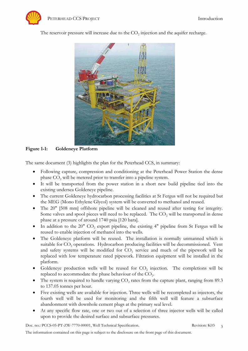
The reservoir pressure will increase due to the CO2 injection and the aquifer recharge.
Figure 1-1: Goldeneye Platform
The same document (3) highlights the plan for the Peterhead CCS, in summary:
Following capture, compression and conditioning at the Peterhead Power Station the dense
phase CO2 will be metered prior to transfer into a pipeline system.
It will be transported from the power station in a short new build pipeline tied into the
existing undersea Goldeneye pipeline.
The current Goldeneye hydrocarbon processing facilities at St Fergus will not be required but
the MEG (Mono Ethylene Glycol) system will be converted to methanol and reused.
The 20" [508 mm] offshore pipeline will be cleaned and reused after testing for integrity.
Some valves and spool pieces will need to be replaced. The CO2 will be transported in dense
phase at a pressure of around 1740 psia [120 bara].
In addition to the 20" CO2 export pipeline, the existing 4" pipeline from St Fergus will be
reused to enable injection of methanol into the wells.
The Goldeneye platform will be reused. The installation is normally unmanned which is
suitable for CO2 operations. Hydrocarbon producing facilities will be decommissioned. Vent
and safety systems will be modified for CO2 service and much of the pipework will be
replaced with low temperature rated pipework. Filtration equipment will be installed in the
platform.
Goldeneye production wells will be reused for CO2 injection. The completions will be
replaced to accommodate the phase behaviour of the CO2.
The system is required to handle varying CO2 rates from the capture plant, ranging from 89.3
to 137.05 tonnes per hour.
Five existing wells are available for injection. Three wells will be recompleted as injectors, the
fourth well will be used for monitoring and the fifth well will feature a subsurface
abandonment with downhole cement plugs at the primary seal level.
At any specific flow rate, one or two out of a selection of three injector wells will be called
upon to provide the desired surface and subsurface pressures.

PETERHEAD CCS PROJECT Introduction
Doc. no.: PCCS-05-PT-ZW-7770-00001, Well Technical Specification. Revision: K03
The information contained on this page is subject to the disclosure on the front page of this document.
4
Transient well operations (closing-in, starting-up and subsurface safety valve (SSSV) testing)
are operations which require attention and monitoring.
Late in injection life as the CO2 plume grows the value of information from well monitoring
will reduce allowing the monitor well to be used as a spare late-life injector.
The fifth well will be a subsurface abandonment with downhole cement plugs at the primary
seal level. Monitoring of this partially abandoned well would be performed during the project
injection period. Information will be gained for assessing the final abandonment of this well
and the rest of the injectors at the end of the life of the project.
CO2 injection rates will be metered at the platform and at the wells and integrity monitoring
will take place. Conformance monitoring of the CO2 injection will be executed as will
containment and environmental monitoring.
The wells each have a non-cemented completion with gravel pack and sand screens. These
are to be re-used. The risk of plugging posed to these completions from fines in the offshore
pipeline (residual after cleaning or from potential de-lamination of an internal coating) is
being mitigated by the installation of a filtration package on the platform.
The CO2 injection facilities will be decommissioned at least 1.5 years after the end of injection
and post-closure monitoring will be executed until handover of the CO2 store to the UK
authority.
The CO2 will be injected into the storage site at a depth >8255 ft [2516 m] below sea level into the
previously gas bearing portion of the high quality Captain Sandstone Member – in total a 130 km
long and <10 km wide ribbon of Lower Cretaceous turbiditic sandstone fringing the southern margin
of the South Halibut Shelf, from UKCS block 13/23 to block 21/2. At the Goldeneye field, this
sandstone has permeability of between 700 and 1500 mD.
Since 2004, the field produced 568 Bscf [16.1 Bscm] of gas and 23 MMbbl [3657 MMl] of
condensate. During production, the field experienced moderate to strong aquifer support – which
also served to end the gas production from the wells as each well sequentially cut water.
The primary CO2 storage mechanism will be accommodation in the pore space previously occupied
by the produced gas and condensate from the Goldeneye field. A secondary mechanism will be
immobile capillary trapping in the water-leg below the original hydrocarbon accumulation combined
with dissolution of CO2 in the formation water.
When CO2 is injected into the field it will displace the invaded aquifer back into the aquifer. The CO2
will form a layer due to gravity and unstable displacement effects and some of the injected CO2 be
displaced towards and possibly below the original oil-water contact. Once CO2 injection has stopped
the CO2 is predicted to flow back into the originally gas bearing structure. However, between 20%
and 30% of the CO2 that was displaced into the water-leg will remain trapped in place due to capillary
forces.

PETERHEAD CCS PROJECT Introduction
Doc. no.: PCCS-05-PT-ZW-7770-00001, Well Technical Specification. Revision: K03
The information contained on this page is subject to the disclosure on the front page of this document.
5
Figure 1-2: CO2 plume after injection. Green: hydrocarbon, Red: CO2, Blue: water
Analysis and modelling have shown that the field and water-leg have sufficient capacity to store over
30 million tonnes of CO2 – more than sufficient for the 15 million tonnes proposed in the UK
competition.
The Goldeneye field is hydraulically connected through the Captain Aquifer water-leg to the
neighbouring fields in the east (Hannay, 14/29a-4 discovery – named Hoylake by Shell – and
Rochelle) and in the west (the no longer producing Atlantic & Cromarty fields and, potentially the
still producing Blake field). The pressure support from the Captain Aquifer has limited the decline in
Goldeneye pressure, from an original of 262 bara to a little under ~145 bara (at datum level of 2560
m [8400 ft] TVDSS).
Injection of 15 million tonnes of CO2 will raise the pressure in the main interval, the Captain D to
around ~259 bara at the end of injection.
Vertical containment is provided by the 130 m thick storage seal, a package including part of the Upper
Valhall Formation, Rødby Formation, Hidra Formation and the Plenus Marl Bed. No gas chimneys
are observed above the Goldeneye complex. The sealing capacity of the Rødby Formation is
considered to be excellent as it acts as the primary seal for all hydrocarbon fields in the Captain
fairway.
The site contains four exploration and appraisal (E&A) wells within the Captain reservoir and one
immediately to the north (Figure 1-3). All of the E&A wells have good quality abandonment plugs at
reservoir seal level.

PETERHEAD CCS PROJECT Introduction
Doc. no.: PCCS-05-PT-ZW-7770-00001, Well Technical Specification. Revision: K03
The information contained on this page is subject to the disclosure on the front page of this document.
6
Figure 1-3: Wells in the site (demarked by green line).
1.2. Summary of Content
This document outlines the information needed to define the technical requirements of a well. It
differs from the WFS (2), which looks at how the system works rather than how it is going to be
constructed. The WFS (2) states the requirements and the WTS builds on these and specifies the
activity in more detail.
As part of the project the Goldeneye wells specification changes from hydrocarbon production to
CO2 injection. It is therefore essential to ensure that the wells can accommodate the new conditions
detailed in the WFS (2). This document presents the WTS of the planned base case i.e. well
workovers on the Goldeneye platform for CO2 injection.
The Technical Specification includes:
Well Specification.
Reservoir Information.
Expected injection conditions: rate, pressure and temperature.
Material selection.
Casings, conductor and cement.
Upper completion design.
Lower completion design.
Fluids, completion and packer fluid.
Well start-up requirements.
Well intervention operations.

PETERHEAD CCS PROJECT Introduction
Doc. no.: PCCS-05-PT-ZW-7770-00001, Well Technical Specification. Revision: K03
The information contained on this page is subject to the disclosure on the front page of this document.
7
The Figure 1-4 taken from the WFS (2) summarises the changes required to the existing wells for
conversion to CO2 injection. These requirements were identified early during the select phase and
have been incorporated in the completion and well intervention detailed design. Some of the
highlighted changes such as the SSSV and its qualification are part of ongoing technology maturation
and require further attention during the later phases of the project i.e. execute and operation.

PETERHEAD CCS PROJECT Introduction
Doc. no.: PCCS-05-PT-ZW-7770-00001, Well Technical Specification Revision: K01
The information contained on this page is subject to the disclosure on the front page of this document.
8
Original completion (hydrocarbon production) CCS CompletionChanges
30”
13 3/8”
9 5/8”
Ekofis
Hidra
Tor
Mackerel
Herrin
8641’ – 9 5/8" Production
Captain
Lista
Balmoral
Dorno
Hordalan
Mey
8681’ - Seal assembly
8541’ – PDG 4 ½” or 3 1/2"
2549’ – TRSSSV 4 ½”
Tubing 3 1/2” 9.3#, 13Cr
0
Rodby shale
DTS & PDG cable
Tubing 4 ½” 12.6#, S13Cr
Tubing 4 ½” or 3 1/2", 13Cr
152.5’
30”
Seabed
Depths relative to RKB
548’
TD
9 5/8” TOC
13 3/8”
9 5/8”
8755’ – FIV, Schlumberger
750’ – 30” conductor
7506’ – Theoretical TOC 9 5/8”
Ekofisk
Hidra Marl
Tor
Mackerel
Herring 8528’ – Halliburton HHC packer
Captain
4118’ Lista
Balmoral
Dornoch2578’
Hordaland1837’
7”
4336’
3232’3459’
Mey
4156’ - 20” x 13 3/8” casing shoe
4809’
5961’
8547’
9017’
9166’
9006’ - 10 3/4” x 9 5/8” casing shoe
9154’ - 4” Excluder screens9163’ - 7” pre-drilled Liner
8696’ - SCR2 packer; Top screens
8831’ - TOL 7”Uniflex PBR
8681’ - Seal Assembly, Baker G22
8651’ - Perforated pup
8443’ – PBR, Halliburton 120k shear/20’
8383’ – PDHG, Schlumberger 5 ½”
2549’ – TRSSV Halliburton 7”
Tubing 7” 29#, 13Cr L80, NK3SB
0’
3130’ – 10 ¾” x 9 5/8” casing x/o
704’ – 20” x 13 3/8” casing x/o
8322’ - Tubing 5 ½” 23#, 13Cr L80, NK3SB x/o
Rodby shale8821’
Xover 4 1/2" * 3 1/2"
Xmas tree and tubing hanger to be replaced
Casing Hanger, and wellhead to remain as is
"A" annulus fluid to be changed
" A" annnulus - seawater
" B" annnulus - Oil Based Mud
" C" annnulus - Open to air
"B" and "C" annuli remain the same
Conductor (30") and casing (20 x 13 3/8" and 10 3/4" x 9 5/8") to remain in place.
4 1/2" tubing above SSSV S13Cr tubing material above SSSV
SSSV to be developedControl line and fluid to be designedSSSV depth similar to current completion
4 1/2" - 3 1/2" X-Over setting depth varies from well to well3 1/2" tubing material - 13Cr
Perforated pup joint to be removed
Lower Completion to remain in place
Upper Completion to be recovered from exisiting tail pipe
PBR (polished bore receptacle) to be removed
New Packer - to be set within primary seal. Calliper run in casing for optimal packer setting depth
No changes to cement (CBL to be run during workover)
Installation PDG + DTS for monitoring
Figure 1-4: Summary of changes required during workover for CCS operation.

PETERHEAD CCS PROJECT Goldeneye wells
Doc. no.: PCCS-05-PT-ZW-7770-00001, Well Technical Specification Revision: K01
The information contained on this page is subject to the disclosure on the front page of this document.
9
2. Goldeneye wells
The Goldeneye platform features five suspended gas production wells, with an additional three spare
slots for potential future wells. The five existing wells in the Goldeneye platform were drilled and
completed to produce hydrocarbons from the Captain Sands, Table 2-1 . The abbreviated well names
are used in this document.
Table 2-1: Existing hydrocarbon producer wells in Goldeneye platform
Full well name Abbreviated well name Spudded (batch operations)
DTI 14/29a-A3 GYA01 8/12/2003
DTI 14/29a-A4Z GYA02S1 13/12/2003
DTI 14/29a-A4 GYA02 13/12/2003
DTI 14/29a-A5 GYA03 19/12/2003
DTI 14/29a-A1 GYA04 5/10/2003
DTI 14/29a-A2 GYA05 2/12/2003
The field was granted CoP (Cessation of Production) from DECC (Department of Energy and
Climate Change) in 2011. There are therefore no plans to produce the wells in the future.
For completeness information from the Conceptual Completion & Well Intervention Design Report
(Key Knowledge Deliverable 11.093) (1) and WFS (2) has been included in this section.
2.1. Existing wells construction summary
The existing wells construction summary is presented below in Table 2-2:
Table 2-2: General well construction characteristics
Attribute Value/Data
On/Offshore Offshore
Well type Previously Hydrocarbon producer.
Currently closed in and suspended with deep set downhole plugs
To be converted to CO2 injection
DFE 152.5ft (46.5m) (Drilling Rig)
Water depth 395ft [120.4m]
Number of wells 5 existing, 3 slots available.
Top reservoir (ft TVDSS) Approximately 8300ft [2529.84m]

PETERHEAD CCS PROJECT Goldeneye wells
Doc. no.: PCCS-05-PT-ZW-7770-00001, Well Technical Specification Revision: K01
The information contained on this page is subject to the disclosure on the front page of this document.
10
The five Goldeneye wells are of similar construction. Figure 2-1, provides a simplified schematic of
one of the existing wells (GYA01).
Figure 2-1: GYA01. Summary of existing completion schematic
Note: Not to scale
AHD
(ft)
TVD
(ft)
20 x 13 3/8" X-Over 704 704 30" Conductor 750 749.75
TRSSSV 2549 2525
10 3/4" x 9 5/8" Casing X-Over 3130 3090
13 3/8" Shoe 4156 4076
7 x 5 1/2" Tubing X-Over 8322 7805
Gauge Mandrel 8383 7859
PBR (Not sheared) 8443 7911
9 5/8" Halliburton Packer 8528 7986
Perforated Pup Joint 8651 8094
9 5/8" Baker Seal Assembly 8681 8121 9 5/8" Baker Packer 8696 8134
5" Baker Ratcheting Mule 8705 8142 7" x 5 " X-Over 8744 8176
FIV 8755 8186
5" x 4" X-Over 8785 8212
Liner Hanger 8831 8253
4" Baker screens 8952 9 5/8" casing shore 9006 8408
7" Predrilled liner
Baker Screens Bull Nose 9154 8539 Pre-drilled liner Shoe 9163 8547 TD 9166 8550

PETERHEAD CCS PROJECT Goldeneye wells
Doc. no.: PCCS-05-PT-ZW-7770-00001, Well Technical Specification Revision: K01
The information contained on this page is subject to the disclosure on the front page of this document.
11
The upper and lower completion of the current wells comprises of:
Upper Completion
SSSV 5.875'' [149mm], 7'' tubing 6.184'', 5'' tubing 4.67'', PDG 4.576'', Polished Bore
Receptacle (PBR) 4.577'', Packer 4.65''
Lower Completion
Formation Isolation Valve (FIV) 2.94'', Screens 3.548'', X-over 3.515''
The maximum well deviation (measurement of a borehole's departure from the vertical) is shown in
Table 2-3 below:
Table 2-3: Well deviation of the existing wells
Well Name Deviation (°)
GYA-01 36
GYA-02S1 60
GYA-03 40
GYA-04 68
GYA-05 7 (shortest well)
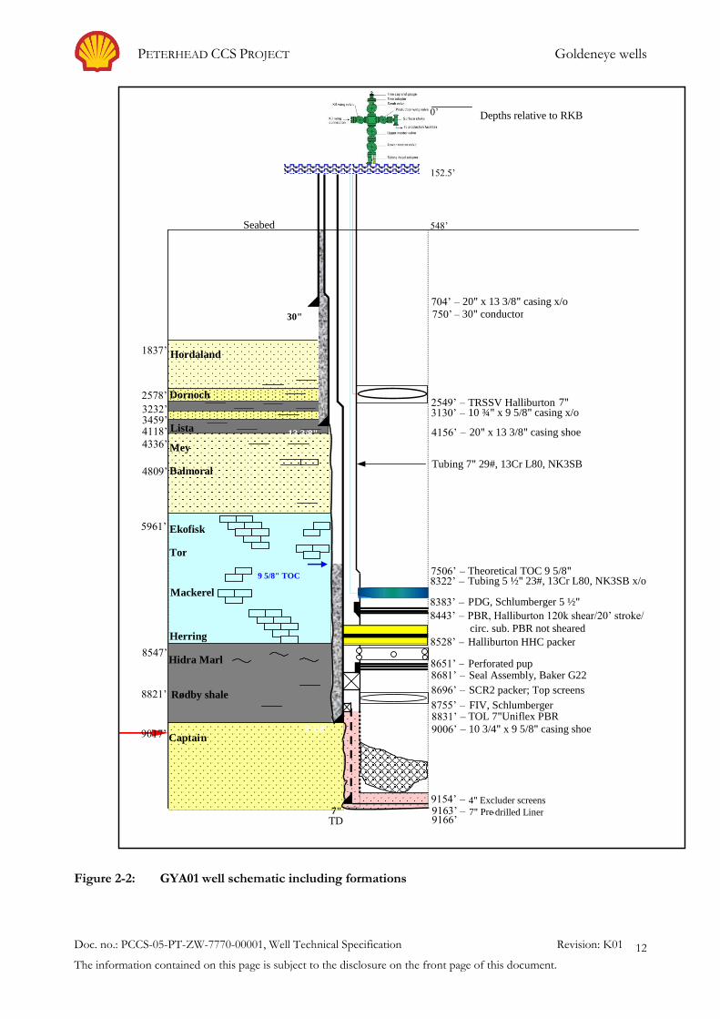
The existing well construction elements with respect to the different formations (the wells are similar
with the difference that the packer is set at different formations) are shown in Figure 2-2. GYA02S1
is the sidetrack of well GYA02
PETERHEAD CCS PROJECT Goldeneye wells
Doc. no.: PCCS-05-PT-ZW-7770-00001, Well Technical Specification Revision: K01
The information contained on this page is subject to the disclosure on the front page of this document.
12
Figure 2-2: GYA01 well schematic including formations
152.5’
30"
Seabed
Depths relative to RKB
548’
TD
9 5/8" TOC
13 3/8"
9 5/8"
8755’ – FIV, Schlumberger
750’ –
30" conductor
7506’ – Theoretical TOC 9 5/8"
Ekofisk
Hidra Marl
Tor
Mackerel
Herring 8528’ – Halliburton HHC packer
Captai n
4118’ Lista
Balmoral
Dornoch 2578’
Hordaland 1837’
7"
4336’
3232’ 3459’
Mey 4156’ –
20" x 13 3/8" casing shoe
4809’
5961’
8547’
9017’
9166’
9006’ –
10 3/4" x 9 5/8" casing shoe
9154’ –
4" Excluder screens 9163’ –
7" Pre - drilled Liner
8696’ –
SCR2 packer; Top screens
8831’ –
TOL 7"Uniflex PBR
8681’ – Seal Assembly, Baker G22 8651’ – Perforated pup
8443’ – PBR, Halliburton 120k shear/20’ stroke/ circ. sub. PBR not sheared
8383’ – PDG, Schlumberger 5 ½"
2549’ – TRSSV Halliburton 7"
Tubing 7" 29#, 13Cr L80, NK3SB
0 ’
3130’ – 10 ¾" x 9 5/8" casing x/o
704’ – 20" x 13 3/8" casing x/o
8322’ –
Tubing 5 ½" 23#, 13Cr L80, NK3SB x/o
Rødby shale 8821’
PETERHEAD CCS PROJECT Goldeneye wells
Doc. no.: PCCS-05-PT-ZW-7770-00001, Well Technical Specification Revision: K01
The information contained on this page is subject to the disclosure on the front page of this document.
13
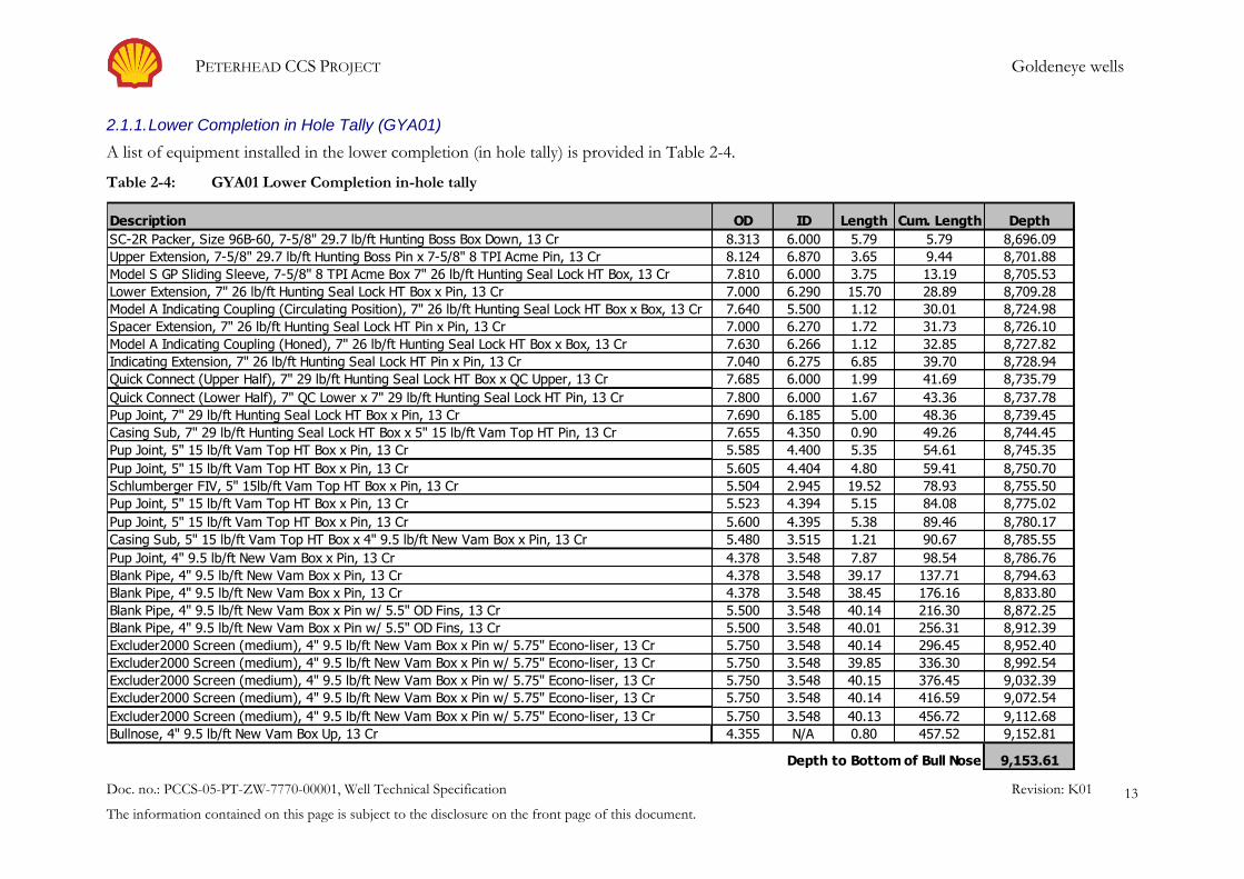
2.1.1. Lower Completion in Hole Tally (GYA01)
A list of equipment installed in the lower completion (in hole tally) is provided in Table 2-4.
Table 2-4: GYA01 Lower Completion in-hole tally
Depth to
GYA-01 Lower Completion In Hole Tally - Sand Control Packer and Screens Top of Tool
Description OD ID Length Cum. Length Depth
SC-2R Packer, Size 96B-60, 7-5/8" 29.7 lb/ft Hunting Boss Box Down, 13 Cr 8.313 6.000 5.79 5.79 8,696.09
Upper Extension, 7-5/8" 29.7 lb/ft Hunting Boss Pin x 7-5/8" 8 TPI Acme Pin, 13 Cr 8.124 6.870 3.65 9.44 8,701.88
Model S GP Sliding Sleeve, 7-5/8" 8 TPI Acme Box 7" 26 lb/ft Hunting Seal Lock HT Box, 13 Cr 7.810 6.000 3.75 13.19 8,705.53
Lower Extension, 7" 26 lb/ft Hunting Seal Lock HT Box x Pin, 13 Cr 7.000 6.290 15.70 28.89 8,709.28
Model A Indicating Coupling (Circulating Position), 7" 26 lb/ft Hunting Seal Lock HT Box x Box, 13 Cr 7.640 5.500 1.12 30.01 8,724.98
Spacer Extension, 7" 26 lb/ft Hunting Seal Lock HT Pin x Pin, 13 Cr 7.000 6.270 1.72 31.73 8,726.10
Model A Indicating Coupling (Honed), 7" 26 lb/ft Hunting Seal Lock HT Box x Box, 13 Cr 7.630 6.266 1.12 32.85 8,727.82
Indicating Extension, 7" 26 lb/ft Hunting Seal Lock HT Pin x Pin, 13 Cr 7.040 6.275 6.85 39.70 8,728.94
Quick Connect (Upper Half), 7" 29 lb/ft Hunting Seal Lock HT Box x QC Upper, 13 Cr 7.685 6.000 1.99 41.69 8,735.79
Quick Connect (Lower Half), 7" QC Lower x 7" 29 lb/ft Hunting Seal Lock HT Pin, 13 Cr 7.800 6.000 1.67 43.36 8,737.78
Pup Joint, 7" 29 lb/ft Hunting Seal Lock HT Box x Pin, 13 Cr 7.690 6.185 5.00 48.36 8,739.45
Casing Sub, 7" 29 lb/ft Hunting Seal Lock HT Box x 5" 15 lb/ft Vam Top HT Pin, 13 Cr 7.655 4.350 0.90 49.26 8,744.45
Pup Joint, 5" 15 lb/ft Vam Top HT Box x Pin, 13 Cr 5.585 4.400 5.35 54.61 8,745.35
Pup Joint, 5" 15 lb/ft Vam Top HT Box x Pin, 13 Cr 5.605 4.404 4.80 59.41 8,750.70
Schlumberger FIV, 5" 15lb/ft Vam Top HT Box x Pin, 13 Cr 5.504 2.945 19.52 78.93 8,755.50
Pup Joint, 5" 15 lb/ft Vam Top HT Box x Pin, 13 Cr 5.523 4.394 5.15 84.08 8,775.02
Pup Joint, 5" 15 lb/ft Vam Top HT Box x Pin, 13 Cr 5.600 4.395 5.38 89.46 8,780.17
Casing Sub, 5" 15 lb/ft Vam Top HT Box x 4" 9.5 lb/ft New Vam Box x Pin, 13 Cr 5.480 3.515 1.21 90.67 8,785.55
Pup Joint, 4" 9.5 lb/ft New Vam Box x Pin, 13 Cr 4.378 3.548 7.87 98.54 8,786.76
Blank Pipe, 4" 9.5 lb/ft New Vam Box x Pin, 13 Cr 4.378 3.548 39.17 137.71 8,794.63
Blank Pipe, 4" 9.5 lb/ft New Vam Box x Pin, 13 Cr 4.378 3.548 38.45 176.16 8,833.80
Blank Pipe, 4" 9.5 lb/ft New Vam Box x Pin w/ 5.5" OD Fins, 13 Cr 5.500 3.548 40.14 216.30 8,872.25
Blank Pipe, 4" 9.5 lb/ft New Vam Box x Pin w/ 5.5" OD Fins, 13 Cr 5.500 3.548 40.01 256.31 8,912.39
Excluder2000 Screen (medium), 4" 9.5 lb/ft New Vam Box x Pin w/ 5.75" Econo-liser, 13 Cr 5.750 3.548 40.14 296.45 8,952.40
Excluder2000 Screen (medium), 4" 9.5 lb/ft New Vam Box x Pin w/ 5.75" Econo-liser, 13 Cr 5.750 3.548 39.85 336.30 8,992.54
Excluder2000 Screen (medium), 4" 9.5 lb/ft New Vam Box x Pin w/ 5.75" Econo-liser, 13 Cr 5.750 3.548 40.15 376.45 9,032.39
Excluder2000 Screen (medium), 4" 9.5 lb/ft New Vam Box x Pin w/ 5.75" Econo-liser, 13 Cr 5.750 3.548 40.14 416.59 9,072.54
Excluder2000 Screen (medium), 4" 9.5 lb/ft New Vam Box x Pin w/ 5.75" Econo-liser, 13 Cr 5.750 3.548 40.13 456.72 9,112.68
Bullnose, 4" 9.5 lb/ft New Vam Box Up, 13 Cr 4.355 N/A 0.80 457.52 9,152.81
Depth to Bottom of Bull Nose 9,153.61
PETERHEAD CCS PROJECT Goldeneye wells
Doc. no.: PCCS-05-PT-ZW-7770-00001, Well Technical Specification Revision: K01
The information contained on this page is subject to the disclosure on the front page of this document.
14
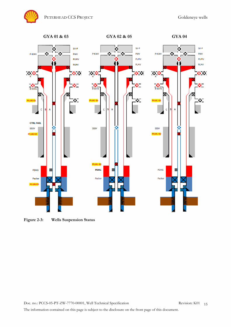
2.1.2. Existing wells status
The field was granted CoP (Cessation of Production) from DECC (Department of Energy and
Climate Change) in 2011. There are therefore no plans to produce the wells in the future.
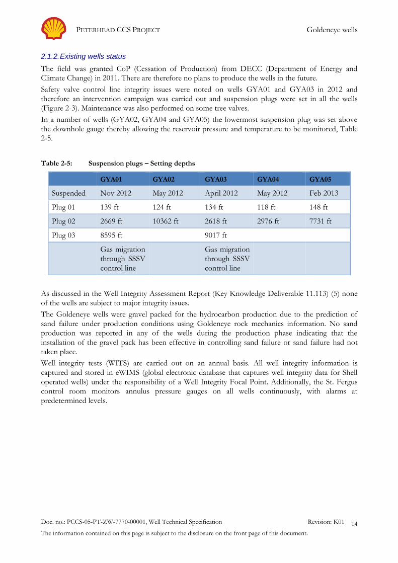
Safety valve control line integrity issues were noted on wells GYA01 and GYA03 in 2012 and
therefore an intervention campaign was carried out and suspension plugs were set in all the wells
(Figure 2-3). Maintenance was also performed on some tree valves.
In a number of wells (GYA02, GYA04 and GYA05) the lowermost suspension plug was set above
the downhole gauge thereby allowing the reservoir pressure and temperature to be monitored, Table
2-5.
Table 2-5: Suspension plugs – Setting depths
GYA01 GYA02 GYA03 GYA04 GYA05
Suspended Nov 2012 May 2012 April 2012 May 2012 Feb 2013
Plug 01 139 ft 124 ft 134 ft 118 ft 148 ft
Plug 02 2669 ft 10362 ft 2618 ft 2976 ft 7731 ft
Plug 03 8595 ft 9017 ft
Gas migration
through SSSV
control line
Gas migration
through SSSV
control line
As discussed in the Well Integrity Assessment Report (Key Knowledge Deliverable 11.113) (5) none
of the wells are subject to major integrity issues.
The Goldeneye wells were gravel packed for the hydrocarbon production due to the prediction of
sand failure under production conditions using Goldeneye rock mechanics information. No sand
production was reported in any of the wells during the production phase indicating that the
installation of the gravel pack has been effective in controlling sand failure or sand failure had not
taken place.
Well integrity tests (WITS) are carried out on an annual basis. All well integrity information is
captured and stored in eWIMS (global electronic database that captures well integrity data for Shell
operated wells) under the responsibility of a Well Integrity Focal Point. Additionally, the St. Fergus
control room monitors annulus pressure gauges on all wells continuously, with alarms at
predetermined levels.
PETERHEAD CCS PROJECT Goldeneye wells
Doc. no.: PCCS-05-PT-ZW-7770-00001, Well Technical Specification Revision: K01
The information contained on this page is subject to the disclosure on the front page of this document.
15
GYA 01 & 03 GYA 02 & 05 GYA 04
Figure 2-3: Wells Suspension Status

PETERHEAD CCS PROJECT Goldeneye wells
Doc. no.: PCCS-05-PT-ZW-7770-00001, Well Technical Specification Revision: K01
The information contained on this page is subject to the disclosure on the front page of this document.
16
2.2. Peterhead – Goldeneye CCS Information
2.2.1. General Information
The Table 2-6 below summarises key metadata from Goldeneye platform and reservoir.
Table 2-6: Goldeneye General Information
Attribute Value/Data
Name Goldeneye
Area North Sea
Located 100 km northeast of St Fergus
Basin South Halibut Basin of the Outer Moray Firth
Platform Normally Unattended Installation (NUI)
Legs 4
Pipeline to shore 102 km, 20" [508mm] diameter
Reservoir Lower cretaceous Captain sandstone
Captain E, D (main) and C (not penetrated by the existing wells)
2.2.2. Goldeneye field - Geology
The injection reservoir is the Captain Sandstone (Figure 2-4). Vertical containment is provided by the
300 m thick primary storage seal, a package including part of the Upper Valhall Formation, Rødby
Formation, Hidra Formation and the Plenus Marl Bed.

PETERHEAD CCS PROJECT Goldeneye wells
Doc. no.: PCCS-05-PT-ZW-7770-00001, Well Technical Specification Revision: K01
The information contained on this page is subject to the disclosure on the front page of this document.
17
Figure 2-4: Main Stratigraphy for Goldeneye area, average depths of formation tops
Seabed
Depths TVSS
390 ’
TD
8400 ’
7890 ’
4445 ’
Ekofisk
Plenus/Hidra Marl
Tor Mackerel
Herring
1 1400 ’
Kimmeridge
Heather
Pentland
Smith Bank
Zechstein
Rotliegend
Captain
3821 ’
Balmoral
Mey
Dornoch 2 564 ’
Ho rdaland 168 2 ’
0 ’
3412 ’ Lista
3211 ’
4121 ’
Rødby shale 8 150 ’
1 0050 ’
9 482 ’
1 1 043 ’
5778 ’
885 0 ’
9 779 ’
8378 ’
5536 ’ 562 0 ’
7772 ’
6327 ’
Maureen
Valhall (Upper)
8 6 00 ’ Valhall (Lower)
Yawl/Scapa/Burns
Chalk features low permeability, but no
sealing capacity due to micro fractures
Lista shales are the secondary seal in the
stratigraphy
Dornoch and shallower formations are
believed to be in communication with each
other and to seabed
Rødby shales and Hidra marl are the main
seal above the injection reservoir
Balmoral sands are water bearing permeable
sandstone, covered by impermeable shales
Captain sands are the CO2 injection reservoir
Thick layers of Kimmeridge and Heather
shales prevent CO2 from migrating
downwards to permeable reservoirs

PETERHEAD CCS PROJECT Goldeneye wells
Doc. no.: PCCS-05-PT-ZW-7770-00001, Well Technical Specification Revision: K01
The information contained on this page is subject to the disclosure on the front page of this document.
18
2.2.3. Reservoir Characteristics
The reservoir characteristics are summarised in Table 2-7 below:
Table 2-7: Reservoir Characteristics
Attribute Value/Data
Type Sandstone
Captain formation
Formation temperature Approximately 83°C @ 8400 ft [2560m] TVDSS
Lower temperature to be encountered during injection
Formation Water Present in the bottom of the well.
Water will be initially at the sand face. Evidence of water from
downhole pressure gauges in GYA03.
Formation water around the wellbore will reduce significantly after 6 to
9 months of continuous CO2 injection. However, water might return
after long periods of no injection or insufficient cumulative volume.
Average Reservoir
(Captain D) Porosity
and Permeability
~25% porosity
790 mD permeability
The Captain D is a clean sandstone with very high Net to Gross
Captain D presented an excellent connectivity during the hydrocarbon
production phase.
Pressure Regime (The pressure regime is given as an indication for general
well/completion design selection. It will be re-calculated before any
well operation and before working over the wells).
An active aquifer supports the field. All the wells are currently shut in
due to water breakthrough and isolated with deep and shallow
downhole plugs.
Original Reservoir Pressure ~ 3815 psia [263bara] @datum 8400 ft
TVDss
Minimum Reservoir pressure after depletion ~ 2100 psia @ datum
Current pressure is ~2650 psia (@ end of December 2013) @ datum
Minimum expected reservoir pressure before CO2 injection
(approximately Year 2019): 2650 psia, Pressure Gradient Range - 0.319
psi/ft
(see note below)
Maximum expected reservoir pressure after 10 million tonne of CO2–
(~Year 2031) 3450 psia, Pressure Gradient: 0.416 psi/ft
Information is of enough quality for this analysis/report on WFS.
Different section of tubing (4 ½" and 3 ½") to be installed in each well
will depend on this information.
Note: Current reservoir pressure is 2680 psia at end of November 2014. Maximum expected reservoir pressure
after 15 years of injection is ~ 3800 psia.

PETERHEAD CCS PROJECT Goldeneye wells
Doc. no.: PCCS-05-PT-ZW-7770-00001, Well Technical Specification Revision: K01
The information contained on this page is subject to the disclosure on the front page of this document.
19
2.2.4. Fluids Characteristics
The fluids characteristics are summarised in Table 2-8 below:
Table 2-8: Fluids characteristics
Attribute Data
CO2 Dehydrated CO2 will be available at the platform level.
CO2 specification as follows:
Compound Fraction mol.
CO2 0.999883
N2 0.000061
O2 0.000001
H2O 0.000050
H2 0.000005
O2 level specification is determined by the presence of 13Cr
material in the wells (lower completion).
Water is controlled to avoid hydrates and corrosion in the offshore
pipeline (50 ppm mol. of water = 20 ppm weight of water).
Formation Water Prior to injection, water will be initially at the sand face. Water
breakthrough observed in all wells during the production phase.
Evidence of water from downhole pressure gauges in GYA03.
Salinity- Total Dissolved Solids (TDS): ~56000 ppm (52000 ppm –
Sodium Chloride - NaCl)
Water level in the wells is currently not known.
It is expected to have more water in the wells at the workover time
due to aquifer presence.
Hydrocarbon Gas – Condensate
0.37% mol. CO2
0% H2S
No solids production observed in the facilities
There was a thin (7m) oil rim in the reservoir at original conditions.
PETERHEAD CCS PROJECT Goldeneye wells
Doc. no.: PCCS-05-PT-ZW-7770-00001, Well Technical Specification Revision: K01
The information contained on this page is subject to the disclosure on the front page of this document.
20
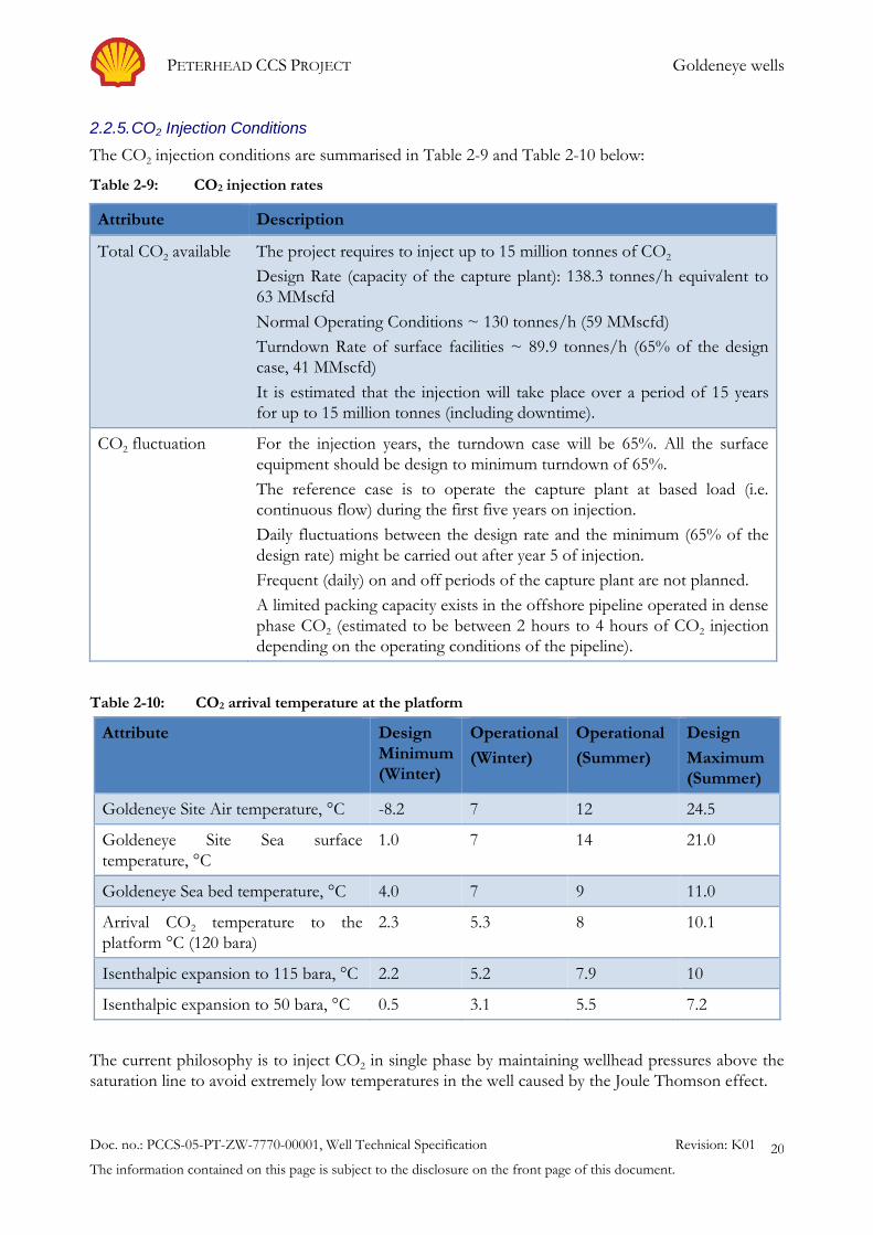
2.2.5. CO2 Injection Conditions
The CO2 injection conditions are summarised in Table 2-9 and Table 2-10 below:
Table 2-9: CO2 injection rates
Attribute Description
Total CO2 available The project requires to inject up to 15 million tonnes of CO2
Design Rate (capacity of the capture plant): 138.3 tonnes/h equivalent to
63 MMscfd
Normal Operating Conditions ~ 130 tonnes/h (59 MMscfd)
Turndown Rate of surface facilities ~ 89.9 tonnes/h (65% of the design
case, 41 MMscfd)
It is estimated that the injection will take place over a period of 15 years
for up to 15 million tonnes (including downtime).
CO2 fluctuation For the injection years, the turndown case will be 65%. All the surface
equipment should be design to minimum turndown of 65%.
The reference case is to operate the capture plant at based load (i.e.
continuous flow) during the first five years on injection.
Daily fluctuations between the design rate and the minimum (65% of the
design rate) might be carried out after year 5 of injection.
Frequent (daily) on and off periods of the capture plant are not planned.
A limited packing capacity exists in the offshore pipeline operated in dense
phase CO2 (estimated to be between 2 hours to 4 hours of CO2 injection
depending on the operating conditions of the pipeline).
Table 2-10: CO2 arrival temperature at the platform
Attribute Design
Minimum
(Winter)
Operational
(Winter)
Operational
(Summer)
Design
Maximum
(Summer)
Goldeneye Site Air temperature, °C -8.2 7 12 24.5
Goldeneye Site Sea surface
temperature, °C
1.0 7 14 21.0
Goldeneye Sea bed temperature, °C 4.0 7 9 11.0
Arrival CO2 temperature to the
platform °C (120 bara)
2.3 5.3 8 10.1
Isenthalpic expansion to 115 bara, °C 2.2 5.2 7.9 10
Isenthalpic expansion to 50 bara, °C 0.5 3.1 5.5 7.2
The current philosophy is to inject CO2 in single phase by maintaining wellhead pressures above the
saturation line to avoid extremely low temperatures in the well caused by the Joule Thomson effect.
PETERHEAD CCS PROJECT Goldeneye wells
Doc. no.: PCCS-05-PT-ZW-7770-00001, Well Technical Specification Revision: K01
The information contained on this page is subject to the disclosure on the front page of this document.
21
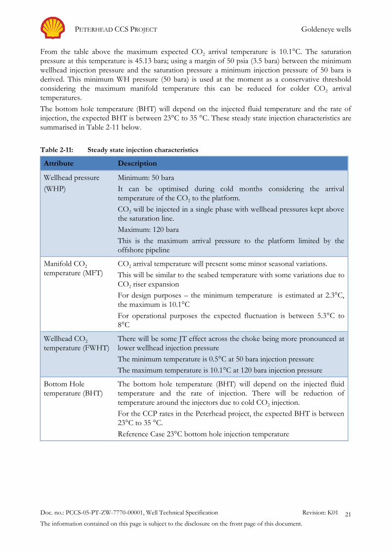
From the table above the maximum expected CO2 arrival temperature is 10.1°C. The saturation
pressure at this temperature is 45.13 bara; using a margin of 50 psia (3.5 bara) between the minimum
wellhead injection pressure and the saturation pressure a minimum injection pressure of 50 bara is
derived. This minimum WH pressure (50 bara) is used at the moment as a conservative threshold
considering the maximum manifold temperature this can be reduced for colder CO2 arrival
temperatures.
The bottom hole temperature (BHT) will depend on the injected fluid temperature and the rate of
injection, the expected BHT is between 23°C to 35 °C. These steady state injection characteristics are
summarised in Table 2-11 below.
Table 2-11: Steady state injection characteristics
Attribute Description
Wellhead pressure
(WHP)
Minimum: 50 bara
It can be optimised during cold months considering the arrival
temperature of the CO2 to the platform.
CO2 will be injected in a single phase with wellhead pressures kept above
the saturation line.
Maximum: 120 bara
This is the maximum arrival pressure to the platform limited by the
offshore pipeline
Manifold CO2
temperature (MFT)
CO2 arrival temperature will present some minor seasonal variations.
This will be similar to the seabed temperature with some variations due to
CO2 riser expansion
For design purposes – the minimum temperature is estimated at 2.3°C,
the maximum is 10.1°C
For operational purposes the expected fluctuation is between 5.3°C to
8°C
Wellhead CO2
temperature (FWHT)
There will be some JT effect across the choke being more pronounced at
lower wellhead injection pressure
The minimum temperature is 0.5°C at 50 bara injection pressure
The maximum temperature is 10.1°C at 120 bara injection pressure
Bottom Hole
temperature (BHT)
The bottom hole temperature (BHT) will depend on the injected fluid
temperature and the rate of injection. There will be reduction of
temperature around the injectors due to cold CO2 injection.
For the CCP rates in the Peterhead project, the expected BHT is between
23°C to 35 °C.
Reference Case 23°C bottom hole injection temperature

PETERHEAD CCS PROJECT Goldeneye wells
Doc. no.: PCCS-05-PT-ZW-7770-00001, Well Technical Specification Revision: K01
The information contained on this page is subject to the disclosure on the front page of this document.
22
2.2.6. Transient conditions (starting-up, closing-in operations)
During transient operations (closing-in and starting-up operations), a temperature drop is observed at
the top of the well for a short period of time. The faster the shut-in or faster the well opening
operation, the less the resultant temperature drop. The cooling effect diminishes deeper into the well
due to limited CO2 flashing and heat transfer from surrounding wellbore.
The reservoir pressure affects the temperature calculation during the transient calculations. The
lower the reservoir pressure, the lower is the surface temperature expected during transient
operations and hence the higher the stresses/impact in terms of well design.
In summary, the expected transient conditions are shown in Table 2-12 as follows:
Table 2-12: Results of transient calculations – design case (base oil in annulus)
Design Case Operating case
Steady State CO2 MFT, °C
Steady State MFP, bara
Reservoir Pressure, psia
3
120.2
2500
-
-
2500
Steady State Conditions
FWHP, bara
FWHT, °C
BHT, °C
45
1
17
115
4
20
Transient conditions
Close in operation, h
Start Up operation, h
2
2
0.5
1
Coldest temperature (wellhead)
Fluid CO2, °C
Average tubing, °C
A annulus, °C
Production casing, °C
-20
-15
-11
-10
-17
-10
-4
-1
Strict operational procedures need to be implemented and adopted by the Goldeneye Well
Operations Group to avoid extreme cooling of the well components due to temperature limitation of
the well components. These are detailed in the Well Operation Guidelines (Key Knowledge
Deliverable 11.104) (6).
Frequent opening-up and closing-in events should be avoided to limit the stresses in the well
(temperature reduction during short periods of time) and to reduce the operation intensity in the
wells.

PETERHEAD CCS PROJECT Goldeneye wells
Doc. no.: PCCS-05-PT-ZW-7770-00001, Well Technical Specification Revision: K01
The information contained on this page is subject to the disclosure on the front page of this document.
23
2.2.7. Closed-in Tubing Head Pressure
The closed in tubing head pressure (CITHP) will depend on the reservoir pressure (or downhole
pressure) and the fluid inside the tubing. Two extreme cases exist: Well filled with CO2 and well filled
with CH4.
The wells will be designed to accommodate water/CO2/gas for corrosion purposes and wellhead
pressures related to hydrocarbon gas filling the tubing.
For a CO2 filled well at the end of the 15 million tonnes injection period, the CITHP is relatively low
(approximately 50 bara) at the maximum predicted reservoir pressure of around 3800 psia (Figure
2-5).
0
10
20
30
40
50
60
70
2000 2500 3000 3500 4000
CIT
HP,
ba
r
Preservoir, psi
CITHP vs Preservoir(Geothermal Gradient)
Figure 2-5: CITHP for a well filled with CO2
Note: Preservoir is reservoir pressure.
In case the well is full of hydrocarbon gas then the predicted CITHP at the same reservoir pressure
(3800 psia) would be in the order of 220 bara (assuming methane filling the tubing), see Figure 2-6.

PETERHEAD CCS PROJECT Goldeneye wells
Doc. no.: PCCS-05-PT-ZW-7770-00001, Well Technical Specification Revision: K01
The information contained on this page is subject to the disclosure on the front page of this document.
24
0
50
100
150
200
250
2500 2700 2900 3100 3300 3500 3700 3900
CIT
HP, b
ar
Bottom Hole Pressure, psi
GYA01 - Closed in ProfileCH4 in the tubing
CITHP
Figure 2-6: CITHP for a well with Methane in the tubing
PETERHEAD CCS PROJECT Goldeneye wells
Doc. no.: PCCS-05-PT-ZW-7770-00001, Well Technical Specification Revision: K01
The information contained on this page is subject to the disclosure on the front page of this document.
25
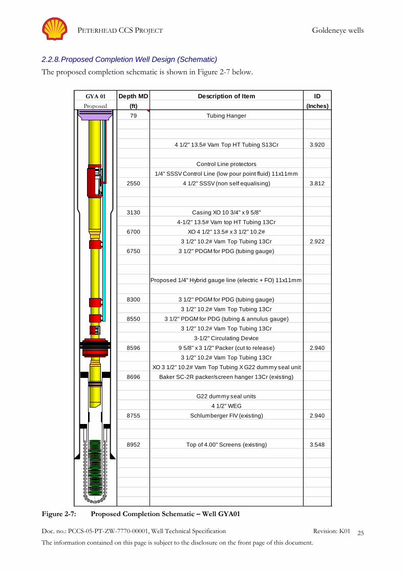
2.2.8. Proposed Completion Well Design (Schematic)
The proposed completion schematic is shown in Figure 2-7 below.
Depth MD ID
(ft) (Inches)
79
3.920
2550 3.812
3130
6700
2.922
6750
8300
8550
8596 2.940
8696
8755 2.940
8952 3.548
GYA 01
Proposed
Top of 4.00" Screens (existing)
4 1/2" 13.5# Vam Top HT Tubing S13Cr
3 1/2" 10.2# Vam Top Tubing 13Cr
1/4" SSSV Control Line (low pour point fluid) 11x11mm
XO 4 1/2" 13.5# x 3 1/2" 10.2#
Description of Item
3 1/2" 10.2# Vam Top Tubing 13Cr
XO 3 1/2" 10.2# Vam Top Tubing X G22 dummy seal unit
Baker SC-2R packer/screen hanger 13Cr (existing)
G22 dummy seal units
4 1/2" WEG
4 1/2" SSSV (non self equalising)
Proposed 1/4" Hybrid gauge line (electric + FO) 11x11mm
3 1/2" PDGM for PDG (tubing & annulus gauge)
3 1/2" PDGM for PDG (tubing gauge)
3 1/2" 10.2# Vam Top Tubing 13Cr
Schlumberger FIV (existing)
3 1/2" 10.2# Vam Top Tubing 13Cr
3-1/2" Circulating Device
4-1/2" 13.5# Vam top HT Tubing 13Cr
Casing XO 10 3/4" x 9 5/8"
Tubing Hanger
3 1/2" PDGM for PDG (tubing gauge)
9 5/8" x 3 1/2" Packer (cut to release)
Control Line protectors
Figure 2-7: Proposed Completion Schematic – Well GYA01

PETERHEAD CCS PROJECT Completion Design & Components
Doc. no.: PCCS-05-PT-ZW-7770-00001, Well Technical Specification Revision: K01
The information contained on this page is subject to the disclosure on the front page of this document.
26
3. Completion Design & Components
The objective of the workover is to provide a well capable of maintaining integrity under CO2
injection and to manage the phase behaviour of the CO2 and limiting the effects of Joule Thomson
(JT) cooling associated with CO2.
The existing Polished Bore Receptacle (PBR) will be replaced as there is concern around its integrity
under CO2 injection. This is due to extreme low CO2 injection temperatures modelled if the existing
completion string (7" x 5 ½" [178mm x 140mm] nominal diameter) is utilised for injection purposes.
This cooling effect will lead to contracting of the tubing and create sufficient force to shear the
120,000 lb [54,431kg] rated shear ring in the PBR. Ensuing movement of the PBR mandrel due to
variations in downhole pressure and temperature will cause the PBR seals to fail. This will allow CO2
to enter the ''A'' Annulus and mix with existing water based completion brine resulting in the
formation of Carbonic Acid. This will have an immediate and significant threat to the integrity of the
9 5/8" L80 casing by corrosion.
Another concern around utilising the existing Goldeneye wells in CO2 injection service is the
presence of a perforated pup joint in the tubing below the production packer which can accelerate
corrosion of the 9 5/8" production casing (see Figure 2-2) due to stagnant water between the existing
completion string and the production casing.
The concerns around using the existing completion for CO2 injection are detailed in the Conceptual
Completions and Well Intervention Design Report (1).
The potential low temperatures pose restrictions in terms of well design including special well
materials, fluids, equipment and procedures. To avoid the low temperatures, the CO2 stream will be
kept in dense phase by increasing the required injection wellhead (WH) pressure above the saturation
line (liquid at the WH). The resultant WH temperature will be in the design range for the wells and
operations. The required extra pressure drop in the well can be achieved by increasing friction or
back pressure. Decreasing the tubing size leads to an increase of the velocity for a particular injection
rate which in turn increases the frictional force in the tubing resulting in an increase of the WH
pressure. With an appropriate change in the upper completion the WH pressure may be increased to
the extent that it lies above the saturation line. As such, the minimum WH pressure in the well is
determined by the requirement to operate the well in single phase.
Another consideration which defines the technical specification is the potential low temperatures
which will be encountered under a highly unlikely isenthalpic expansion of CO2 to atmospheric
pressure. The CO2 phase behaviour is described by Figure 3-1. It is however important to highlight
that these scenarios are highly unlikely.

PETERHEAD CCS PROJECT Completion Design & Components
Doc. no.: PCCS-05-PT-ZW-7770-00001, Well Technical Specification Revision: K01
The information contained on this page is subject to the disclosure on the front page of this document.
27
The CO2 phase behaviour is described by the diagram below.
Figure 3-1: CO2 phase behaviour diagram (7)
The requirement to workover the upper completion provides opportunity to optimise the well design
to be best suited for CO2 injection during the life of the project and future well decommissioning.
The tubing geometry, materials, seals and fluids have all been evaluated and best fit components and
technologies designed into the detailed completion and well intervention design, see proposed
completion schematic Figure 2-7.
The workovers also provide the opportunity to evaluate the cement behind the production casing
(cement bond log, CBL) and to carry out casing analysis to confirm the suitability for placing the new
production packer. This also provides an opportunity to place the new production packer deeper in
the well opposite the Hidra formation which forms part of the primary seal. This also facilitates
future abandonment of the wells as highlighted in the Abandonment Concept for Injection Wells
(Key Knowledge Deliverable 11.100) (8).
The new completion also acts as a means to convey additional downhole instrumentation which
allows for the optimisation of the in-well surveillance.
Suitable annulus fluid and elastomers will also be used as part of the new completion design thereby
enabling the well to operate and maintain integrity under CO2 injection service for the duration of the
project.

PETERHEAD CCS PROJECT Completion Design & Components
Doc. no.: PCCS-05-PT-ZW-7770-00001, Well Technical Specification Revision: K01
The information contained on this page is subject to the disclosure on the front page of this document.
28
3.1. Material/Corrosion
Key well construction materials and their performance in the presence of CO2 are discussed in Table
3-1 below.
Table 3-1: Well Construction Materials
Material Properties
Carbon Steel CO2 in the presence of water will lead to dissolution of CO2, forming
carbonic acid (H2CO3). This will lead to corrosion of carbon steel. The
typical CO2 corrosion rate for carbon steel in contact with water (wet
conditions) will be in the order of 10 mm/yr.
In carbon steel tubulars, CO2 corrosion is mitigated by control of the
water content to avoid formation of free water and to prevent wet
excursions. The water content in the CO2 is specified as below 20
ppmW.
13Cr / S13Cr Even under wet conditions, CO2 corrosion is not a threat for 13Cr steel
under typical Goldeneye injection conditions.
13Cr is susceptible to localised corrosion in wet conditions when O2 is
present. A limit of 1 ppmV for O2 in the CO2, corresponding to a
concentration O2 dissolved in water below 10 ppb (by mass); will
prevent such corrosion from occurring.
Elastomers Elastomers can also absorb gas and suffer explosive decompression
when pressure is reduced. Any elastomer to be in contact with CO2
needs to be checked for its compatibility.
Cement Degradation rates are proportional to temperature, pressure and the
square root of time.
From literature, estimates for cement degradation vary from 0.05 m to
12.36 m in 10,000 years.
Goldeneye conditions are predicted to be approximately 2m in 10,000
years.
3.2. Casing, Conductor and Cement
The base case plan for the workovers involves utilising the existing casing strings and conductors.
The casing strings were cemented in place with a Portland class G based cement slurry. These items
of the well have been evaluated for their suitability for use in CO2 injection without any major
concerns. A summary of the evaluation process is provided in the Conceptual Completion and Well
Intervention Design Endorsement Report (1). For completeness the following information has been
included here with some recent updates from the detailed well design.
3.2.1. 30" Conductor
The 30" conductor was driven 200 ft [61m] into the seabed. The 20'' [508mm] surface casing was
cemented to seabed, but not cemented to surface. Hence the 30'' and 20'' pipes are freestanding and
independent of one another. Load calculations for the worst case corrosion rate (0.5 mm/yr. over a

PETERHEAD CCS PROJECT Completion Design & Components
Doc. no.: PCCS-05-PT-ZW-7770-00001, Well Technical Specification Revision: K01
The information contained on this page is subject to the disclosure on the front page of this document.
29
25 yr. period) conclude that the existing Goldeneye 30" conductors are fit for the expected load cases
for the duration of the extended field life. It follows that no load transfer to the conductor is
expected.
The 30" conductor will not be in direct contact with CO2 and no significant cooling of the carbon
steel conductor is expected.
An additional Pulsed Eddie Current (PEC) survey was carried out in 2014. It is also planned to carry
out periodic Remote Operated Vehicle (ROV) and PEC surveys of the conductor.
3.2.2. 20" x 13 3/8" Surface Casing
The first casing string set inside the conductor was a 20" x 13 3/8" taper string set at around 4150 ft.
The 20" casing features a 1" (25 mm) wall thickness. The 20" casing was cemented to seabed. The
surface casing will not be in contact with the injected CO2.
The 30" conductor and 20" x 13 3/8" casing are freestanding and independent of one another. The
20" surface casing takes all the well loading and does not transfer the load to the 30" conductor.
Goldeneye Platform wells have been analysed with WellCat software. The analysis also models the
conditions of CO2 injection and included a negative wellhead growth calculation to provide an
indication of level of movement expected in the casing strings as the well is cooled down during CO2
injection. Periodic PEC corrosion surveys have been run on both the conductor and the surface
casing. A recent survey was carried out in 2014. Periodic surveys will continue in the future.
It has been concluded that the Goldeneye 20" casing will be good for the expected load cases for the
duration of the extended field life. It follows that no load transfer to the conductor is expected.
3.2.3. 10 ¾ x 9 5/8" Production Casing
The second casing string or 10 ¾" x 9 5/8" taper production casing was set at the bottom of the
Rødby formation. This casing was cemented to approximately 1500 ft AHD above from the casing
shoe.
The position of the production packer in the current completion and the new completion for CO2
injection will be similar but deeper. The production packer in the injectors should be positioned in
the wells across the Hidra marl, considered part of the reservoir seal.
The current corrosion of the production casing above the existing packer is negligible as the
completion fluid used in the A annulus was inhibited seawater installed during the completion
operations. The production casing above the production packer is not expected to be exposed to
free water or CO2 during the injection phase. The new S13Cr and 13Cr tubing will prevent the CO2
contacting this casing string.
Underneath the existing production packer, a section of production casing has been exposed for the
period of approximately 6 years to the hydrocarbon production environment (natural gas with 0.3%
CO2). It is possible that this has led to some corrosion of the casing. As an estimate of maximum
corrosion, assuming wetting for the full 6 years of field production, the corrosion loss is estimated to
be of the order of 0.6 mm. In view of protection by FeCO3 scale and a much shorter wetting period
(wells production was closed in only after the presence of formation water), the actual wall loss is
probably less and of therefore of little significance.
The same section of the carbon steel production casing (underneath the production packer), will be in
contact with the injected fluid. Under normal injection conditions the CO2 corrosion rate is
controlled by the water content in the CO2. However, during non-injection periods, water from the
aquifer might initially come back into the well leading to presence of water and CO2, which can result
in high corrosion rates (10 mm/yr.). Based on an estimated typical CO2 corrosion rate of 10 mm/yr.
it would take a little more than 1 year of wet exposure to corrode through the ½" thickness of the

PETERHEAD CCS PROJECT Completion Design & Components
Doc. no.: PCCS-05-PT-ZW-7770-00001, Well Technical Specification Revision: K01
The information contained on this page is subject to the disclosure on the front page of this document.
30
casing. This implies that to avoid the casing corroding through, wet exposure to the CO2
environment needs to be limited to less than 1 year in total over the required life of the casing.
Even in the scenario of having casing failure and axial cement degradation, the risk of leaking CO2 is
very low. This is based on the estimated matrix properties and the absence of fractures at the Hidra
level. Additionally, during most of the injection period, the pressure of the CO2 downhole will be
lower than the hydrostatic pressure. As such, there is no reason to plan a sidetrack for the potential
of out of zone injection of the CO2 as the marls above the Rødby also present adequate sealing
characteristics.
In the existing well completion (see Figure 2-2), a perforated pup joint is present between the
production packer and the top of the screen hanger; this section creates a stagnant volume between
the tubing and the production casing. It is planned to remove the perforated tubing section during
the workover operations to give more protection to the casing. This is explained further in the section
on well construction (Section 4).
Due to injection of cold CO2, the load cases are driven towards tensile loading due to thermal
contraction. Normal CS shows adequate physical properties down to 0°C. For lower temperatures,
carbon steel requires to be impact tested. Available certificates that support the quality of the
installed production casing were analysed and Charpy values demonstrating adequate toughness down
to -40°C were confirmed.
3.2.4. Cement
The primary cement sheath of the production casing is a barrier to contain the CO2 downhole in the
well. The cement used in the slurry is normal Portland class G cement. The theoretical top of the
cement (TOC) in the B-annulus between 9 5/8'' production casing and the 10 ¾" hole has been
estimated for all five wells during the cementing operations. The cement column from the 9 5/8"
casing shoe to the theoretical TOC is calculated at 1,500 ft. along-hole depth (AHD) above the shoe,
which is well above the formation seals of the reservoir. Cement evaluation logs were not run during
the drilling phase of the wells, but are planned for the workover operations.
The cement is considered of good quality, based on well operation records. The historical records
show that the casing integrity is good as a successful pressure test was achieved after bumping the top
of the cement plug during the production casing section. The historical records of top well annuli
pressures also show that no anomalies have been reported in the B annulus pressures during the
production history of Goldeneye.
The distance between the currently installed production packer and the theoretical TOC is between
1,190 ft and 1,351 ft. AHD depending on the well. The cement is covering the primary seal
formations (Rødby and Hidra) in all five wells up into the Chalk formation. There is sufficient cement
height to ensure a barrier in the B annulus above the production packer.
Given that the TOC is theoretical, it is recommended to run a cement evaluation tool to better assess
the condition of the cement in the B-annulus.
The long term effect of CO2 on cement has been investigated. Cement degradation by CO2 in the
form of carbonic acid is a process that produces an insoluble precipitate that slows degradation.
Several recently published papers examine various experiments and case studies related to the
potential degradation of Portland based cements when exposed to high CO2 environments.
Degradation rates have been found to be proportional to temperature, pressure and the square root
of time. From literature, estimates for cement degradation vary from 0.05 m to 12.36 m in 10,000
years. For Goldeneye conditions it is estimated to be approximately 2 m in 10,000 years.
Diana software, a specialist mechanical cement model was run to ascertain the thermal effects of CO2
injection on Goldeneye. The injection model simulates the thermal effects on the mechanics of the

PETERHEAD CCS PROJECT Completion Design & Components
Doc. no.: PCCS-05-PT-ZW-7770-00001, Well Technical Specification Revision: K01
The information contained on this page is subject to the disclosure on the front page of this document.
31
system (casing/formation/cement). Diana results indicated that the remaining integrity of the cement
is sufficient for CO2 injection in the Goldeneye Platform wells. The remaining capacity of the cement
sheath for various simulated operational scenarios is sufficient for CO2 injection.
3.3. Wellhead, Tree & Tubing hanger
The existing Goldeneye Christmas tree and wellhead is suited to CO2 injection for the specified
steady state operating parameters. The system was primarily designed for gas production, which
makes it a good candidate for CO2 injection. A feasibility study was carried out to evaluate the
suitability of the existing system for CO2 injection. The three main areas of concern are ED
(Explosive Decompression) resistance, corrosion resistance and low temperature performance.
ED (Explosive Decompression) Resistance; The Goldeneye Christmas tree provided good ED
resistance in gas production service. The elastomers, which could be susceptible, are in the annulus
regions, which would require breakdown of the primary seals for them to become exposed to CO2.
If the elastomers were exposed to an ED environment, they would show signs of ED damage on the
side exposed to the gas, however as they are constrained in the groove severe damage does not occur
until the seal is removed allowing it to expand and tear as gas escapes from inside the elastomer.
Corrosion resistance; The existing Goldeneye Christmas tree and wellhead system is resistant to dry
CO2. However if the CO2 becomes wet, it can form carbonic acid, which will corrode carbon steel
and depending upon the Ph. level may corrode stainless steel.
Low temperature performance; The Goldeneye Christmas tree is designed for API 6A temperature
class U (-18°C to 121°C). The 7.00" Tubing Hanger is designed for temperature class S, T, U, V (-
18°C to 121°C). The10-3/4" Casing Hanger is designed for temperature class P-U (-18°C to 82°C).
The 18-3/4" 3 Stage compact housing is designed for U (-18°C to 121°C). Notably the elastomers
reviewed for ED resistance have a greater temperature range than those of the metallic components,
as low as –50°C [-58°F] for some component parts.
As previously stated the Goldeneye Christmas tree and wellhead is suited to CO2 injection for the specified steady state operating parameters for temperatures down to -18°C (0°F). However an analysis of the material specifications revealed that the same metallurgy is utilised on lower temperature rated equipment (API 6A, temperature class ‘K’) with additional (lower temperature) impact tests.
Due to low transient temperatures (in the order of -20°C in the CO2, see Figure 3-2) during opening
and closing of the wells and even lower temperatures which might be encountered in highly unlikely
CO2 release scenarios, surface trees and tubing hangers will require to be changed to low temperature
compatible equipment (API 6A temperature class ‘K’). These well items will be manufactured and
installed as part of the workover operations.
Under uncontrolled leaks, the temperature of the CO2 might get very cold (metal temperatures
estimated at the triple point -56°C and jet temperatures of around -80°C). The Christmas tree and the
tubing hanger can be changed to accommodate this highly unlikely event. However, some well
elements such as the wellhead system and casing hangers cannot be changed. Detailed thermal
simulations of the wellhead/Christmas tree system were carried out to evaluate the extension of the
low temperature during highly unlikely leak scenarios in order to evaluate the suitability of these
components.

PETERHEAD CCS PROJECT Completion Design & Components
Doc. no.: PCCS-05-PT-ZW-7770-00001, Well Technical Specification Revision: K01
The information contained on this page is subject to the disclosure on the front page of this document.
32
Figure 3-2: Well Component Temperature (top well section during transient conditions)
Computational Fluid Dynamic (CFD) modelling was carried out based on predicted temperatures
results from OLGA simulations, see Figure 3-3. The CFD models showed that for small weeps and
seeps and releases of up to 28 mm diameter there is no significant cooling at the wellhead. For larger
releases i.e. 50 mm in diameter modelling revealed that components of the wellhead system will see
an excursion below the design rating. However there is no credible scenario leading to a continuous
release of CO2 from a leak point of such a size. Containment will be achieved via one of the tree
valves.
28 mm 50 mm Scale
Figure 3-3: Computational Fluid Dynamic (CFD) analysis of wellhead system
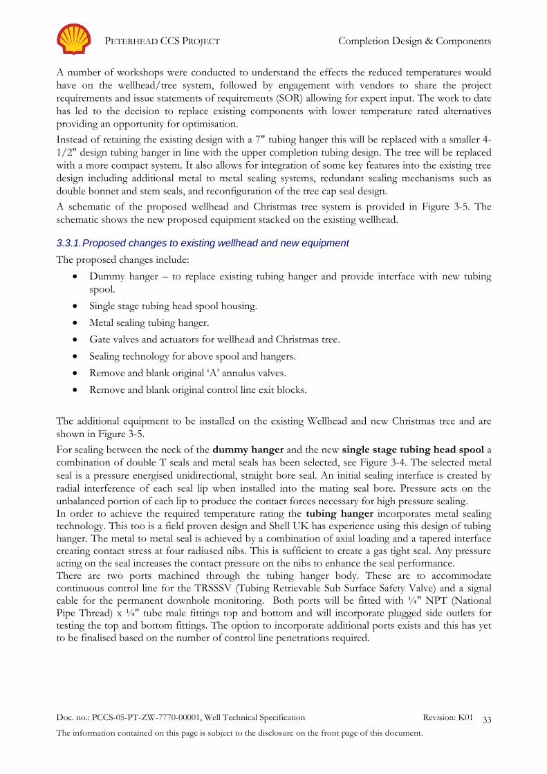
PETERHEAD CCS PROJECT Completion Design & Components
Doc. no.: PCCS-05-PT-ZW-7770-00001, Well Technical Specification Revision: K01
The information contained on this page is subject to the disclosure on the front page of this document.
33
A number of workshops were conducted to understand the effects the reduced temperatures would
have on the wellhead/tree system, followed by engagement with vendors to share the project
requirements and issue statements of requirements (SOR) allowing for expert input. The work to date
has led to the decision to replace existing components with lower temperature rated alternatives
providing an opportunity for optimisation.
Instead of retaining the existing design with a 7" tubing hanger this will be replaced with a smaller 4-
1/2" design tubing hanger in line with the upper completion tubing design. The tree will be replaced
with a more compact system. It also allows for integration of some key features into the existing tree
design including additional metal to metal sealing systems, redundant sealing mechanisms such as
double bonnet and stem seals, and reconfiguration of the tree cap seal design.
A schematic of the proposed wellhead and Christmas tree system is provided in Figure 3-5. The
schematic shows the new proposed equipment stacked on the existing wellhead.
3.3.1. Proposed changes to existing wellhead and new equipment
The proposed changes include:
Dummy hanger – to replace existing tubing hanger and provide interface with new tubing
spool.
Single stage tubing head spool housing.
Metal sealing tubing hanger.
Gate valves and actuators for wellhead and Christmas tree.
Sealing technology for above spool and hangers.
Remove and blank original ‘A’ annulus valves.
Remove and blank original control line exit blocks.
The additional equipment to be installed on the existing Wellhead and new Christmas tree and are
shown in Figure 3-5.
For sealing between the neck of the dummy hanger and the new single stage tubing head spool a
combination of double T seals and metal seals has been selected, see Figure 3-4. The selected metal
seal is a pressure energised unidirectional, straight bore seal. An initial sealing interface is created by
radial interference of each seal lip when installed into the mating seal bore. Pressure acts on the
unbalanced portion of each lip to produce the contact forces necessary for high pressure sealing. In order to achieve the required temperature rating the tubing hanger incorporates metal sealing technology. This too is a field proven design and Shell UK has experience using this design of tubing hanger. The metal to metal seal is achieved by a combination of axial loading and a tapered interface creating contact stress at four radiused nibs. This is sufficient to create a gas tight seal. Any pressure acting on the seal increases the contact pressure on the nibs to enhance the seal performance. There are two ports machined through the tubing hanger body. These are to accommodate continuous control line for the TRSSSV (Tubing Retrievable Sub Surface Safety Valve) and a signal cable for the permanent downhole monitoring. Both ports will be fitted with ¼" NPT (National Pipe Thread) x ¼" tube male fittings top and bottom and will incorporate plugged side outlets for testing the top and bottom fittings. The option to incorporate additional ports exists and this has yet to be finalised based on the number of control line penetrations required.

PETERHEAD CCS PROJECT Completion Design & Components
Doc. no.: PCCS-05-PT-ZW-7770-00001, Well Technical Specification Revision: K01
The information contained on this page is subject to the disclosure on the front page of this document.
34
Figure 3-4: Proposed Single Stage Tubing Head Spool and Dummy Hanger
Note: Figure courtesy of Schlumberger
The proposed Christmas Tree incorporates 4-1/8" production wing, kill wing and top connection with a wirecutting actuator on the Upper Master Valve (UMV) and non-wirecutting actuator on the Flow Wing Valve (FWV). The assembly comprises of a single string solid block, gate valves, tree cap, instrument flange, double block and bleed needle valve, gauge, ring gaskets, studs and nuts all of which have been selected for the ability to perform in the prescribed environment. The grease applied to any of the valves also requires additional attention to ensure its suitability to perform at potentially reduced temperatures. The requirement for double bonnet and stem seals was stipulated for enhanced reliability, again this is a field proven design and has been utilised in the North Sea. It is also proposed to remove the standard quick union profile in the Christmas tree cap in order to remove this elastomeric seal. The quick union is a redundant feature as planned intervention rig up is designed to utilise flanged connections to reduce the potential for small releases. Also the cap to tree connection will be optimised to suit the future intervention requirements and lubricator design. In order to withstand the potential severe low temperatures that occur under the highly unlikely event of an uncontrolled surface release of CO2 the proposed tree and wellhead components will be clad with alloy 625, alloys such as 825 and 718 have also been proposed for some of the components.
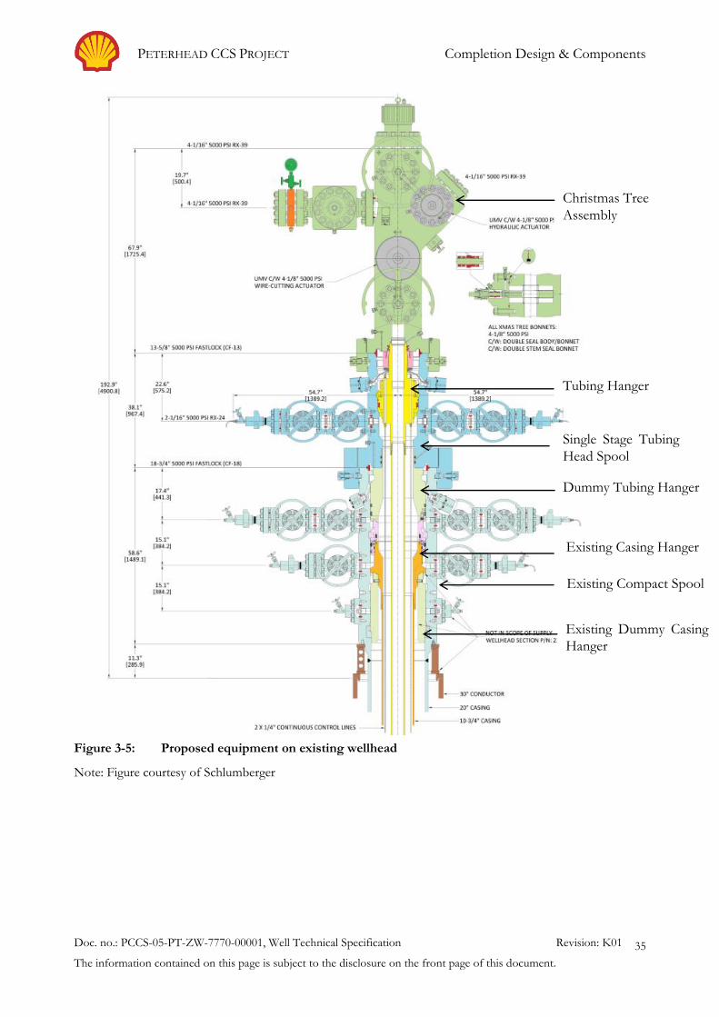
PETERHEAD CCS PROJECT Completion Design & Components
Doc. no.: PCCS-05-PT-ZW-7770-00001, Well Technical Specification Revision: K01
The information contained on this page is subject to the disclosure on the front page of this document.
35
Figure 3-5: Proposed equipment on existing wellhead
Note: Figure courtesy of Schlumberger
Existing Compact Spool
Existing Casing Hanger
Existing Dummy Casing
Hanger
Dummy Tubing Hanger
Single Stage Tubing
Head Spool
Christmas Tree
Assembly
Tubing Hanger

PETERHEAD CCS PROJECT Completion Design & Components
Doc. no.: PCCS-05-PT-ZW-7770-00001, Well Technical Specification Revision: K01
The information contained on this page is subject to the disclosure on the front page of this document.
36
3.4. Tubing Design, Material & Connections
Re-completion of the wells will involve replacing the 7" tubing with a smaller (diameter) size. This is
in order to provide back pressure in the well, thereby keeping the CO2 in single state during injection.
As the pressure and CO2 injection rates will vary over the duration of the project, the injection rates
will be accommodated by different tubing sizes in the injection wells – initial injection period low
rates with smaller tubing and later stage higher rates with larger tubing. This tubing size optimisation
will be based on reservoir pressure, injection rates and power plant power generation cycles. The
optimisation is reflected in the wells by the placement depth of the 4 ½" x 3 ½" crossover, leading to
wells with different operating envelopes, see Table 3-3.
The completion design allows for standardisation of the top and bottom part of the upper
completion. The preferred tubing size in the top of the well (from the tubing hanger to the SSSV) is
4 ½". Considering the low temperatures expected in the top of the well during transient operations it
has been decided to utilise Super 13Cr (S13Cr) tubing in the top of the well (from tubing hanger to
SSSV) which has enhanced physical properties in lower temperatures when compared with 13Cr,
some additional testing of the S13Cr material is required and discussions are underway with the Oil
Country Casing and Tubing (OCTG) supplier. There may also be a requirement to utilise 2 or 3 joints
of alloy 825 tubing directly above the SSSV in order to withstand the potential extreme low
temperatures that will occur at the SSSV flapper in the highly unlikely event of a significant and
continuous surface release of CO2. The involvement with the OCTG supplier on the S13Cr material
properties will also be able to confirm this requirement.
Below the Subsurface Safety Valve (SSSV) 4 ½" 13Cr tubing will be utilised down to the crossover.
At the crossover the tubing will change from 4 ½" 13Cr to 3 ½" 13Cr, see Table 3-2.
There are no plans to replace the existing lower completion which consists of a gravel pack and
premium screens. The lower completion tubing, screens and liner are also 13Cr material. A detailed
study into the use of the existing lower completion for CO2 injection and its suitability was conducted
and no causes were found that would lead to the requirement of a lower completion
workover/sidetrack. The study involved an analysis of the materials, corrosion, screen performance
under reverse flow, plugging and erosion of the screens and formation. The details of this study and
its findings are included in the Conceptual Completion and Well Intervention Design Endorsement
Report (1). A summary of the analysis and its findings is provided in this report.
Table 3-2: Upper completion tubing size and material selection
Tubing Tubing Size
(Inches)
Tubing Weight
(lbs/ft)
Tubing material
Tubing Hanger to SSSV 4 ½ 13.5 S13Cr
2-3 Joints directly above SSSV 4 ½ 13.5 Alloy 825/S13Cr
SSSV to Crossover 4 ½ 13.5 13Cr
Below Crossover 3 ½ 10.2 13Cr
13Cr is susceptible to localised corrosion in wet conditions when O2 is present. Under typical
Goldeneye injection conditions a limit of 1 ppm (by volume) for O2 in the CO2, corresponding to a
concentration O2 dissolved in water below 10 ppb (by mass), will prevent such corrosion from
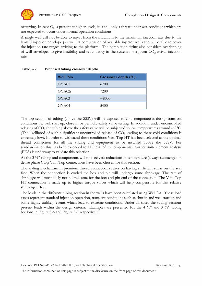
PETERHEAD CCS PROJECT Completion Design & Components
Doc. no.: PCCS-05-PT-ZW-7770-00001, Well Technical Specification Revision: K01
The information contained on this page is subject to the disclosure on the front page of this document.
37
occurring. In case O2 is present at higher levels, it is still only a threat under wet conditions which are
not expected to occur under normal operation conditions.
A single well will not be able to inject from the minimum to the maximum injection rate due to the
limited injection envelope per well. A combination of available injector wells should be able to cover
the injection rate ranges arriving to the platform. The completion sizing also considers overlapping
of well envelopes to give flexibility and redundancy in the system for a given CO2 arrival injection
rate.
Table 3-3: Proposed tubing crossover depths
Well No. Crossover depth (ft.)
GYA01 6700
GYA02s 7200
GYA03 ~8000
GYA04 5400
The top section of tubing (above the SSSV) will be exposed to cold temperatures during transient
conditions i.e. well start up, close in or periodic safety valve testing. In addition, under uncontrolled
releases of CO2 the tubing above the safety valve will be subjected to low temperatures around -60°C.
(The likelihood of such a significant uncontrolled release of CO2 leading to these cold conditions is
extremely low). In order to withstand these conditions Vam Top HT has been selected as the optimal
thread connection for all the tubing and equipment to be installed above the SSSV. For
standardisation this has been extended to all the 4 ½" in components. Further finite element analysis
(FEA) is underway to validate this selection.
As the 3 ½" tubing and components will not see vast reductions in temperature (always submerged in
dense phase CO2) Vam Top connections have been chosen for this section.
The sealing mechanism in premium thread connections relies on having sufficient stress on the seal
face. When the connection is cooled the box and pin will undergo some shrinkage. The rate of
shrinkage will most likely not be the same for the box and pin end of the connection. The Vam Top
HT connection is made up to higher torque values which will help compensate for this relative
shrinkage effect.
The loads in the different tubing section in the wells have been calculated using WellCat. These load
cases represent standard injection operation, transient conditions such as shut in and well start up and
some highly unlikely events which lead to extreme conditions. Under all cases the tubing sections
present loads within the design criteria. Examples are presented for the 4 ½" and 3 ½" tubing
sections in Figure 3-6 and Figure 3-7 respectively.

PETERHEAD CCS PROJECT Completion Design & Components
Doc. no.: PCCS-05-PT-ZW-7770-00001, Well Technical Specification Revision: K01
The information contained on this page is subject to the disclosure on the front page of this document.
38
Figure 3-6: Design limits for 4 1/2" 13.5 lb/ft. S13Cr110 tubing in GYA02S1 proposed completion
Figure 3-7: Design limits for 3 1/2" 10.2 lb/ft. 13Cr L80 tubing in GYA02S1 proposed completion
PETERHEAD CCS PROJECT Completion Design & Components
Doc. no.: PCCS-05-PT-ZW-7770-00001, Well Technical Specification Revision: K01
The information contained on this page is subject to the disclosure on the front page of this document.
39
3.4.1. Flow Induced Vibration and Instability
High fluid velocities are expected in the wells during CO2 injection. These velocities raise concerns
with respect to flow-induced vibration and the effect that this condition may have on the tubing and
tubing connections. In order to eliminate this as a potential risk to the integrity of the tubing string a
vibration analysis was undertaken. The scope of the analysis was to make an assessment of the
mechanical integrity of the tubing crossovers due to internal excitation of the fluid resulting from
high fluid velocities. The results of the analysis are discussed in the Well Completion Concept Select
(Key Knowledge Deliverable 11.097) (9). As a result of the analysis a maximum velocity in the tubing
of 12 m/s will be used to restrict the wells envelope.
The 12 m/s maximum velocity is equivalent to having the following injection rates in different tubing sizes (see Table 3-4).
Table 3-4: Maximum injection limit due to velocity in tubing
Tubing Size,
(inch)
Internal
Diameter, (inch)
In-situ Injection Rate for
12 m/s in the tubing,
m3/d
Injection Rate for 12 m/s
in tubing, MMscfd
(CO2 ~ 970m m3/d)
4 ½" 3.958 8230 120
3 ½" 2.922 4700 68
With 3 ½" tubing the maximum injection rate per well would be 68 MMscfd which is higher than the capacity of the capture plant (63 MMscfd).
3.4.2. Low Temperature Material Embrittlement
From modelling the CO2 temperature during transient conditions is predicted to be in the order of
-20°C. The tubing temperature will be in the order of -15°C. The estimated effect on the production
(10 ¾'' x 9 5/8'') casing is that the temperature will drop to -10°C.
Minimum service temperatures for metals are listed in Shell design standards. When the metals cool,
they lose toughness, which could then become an issue when subjected to mechanical load. The
minimum service temperature of metals is the temperature above which they will show acceptable
toughness if subjected to shock loading.
For standard 13Cr steel, the minimum service temperature of -30°C is well below the expected -15°C
for the tubing wall. In addition to the transient conditions another hypothetical (highly unlikely)
scenario was modelled involving a release of CO2 at surface. If the leak size is modelled to be
conservatively large it indicated cooling of the tubing to -60°C. It is for this reason that Super 13Cr
has been selected for the tubing material above the SSSV. Super 13Cr shows adequate toughness
down to the prescribed temperatures but requires impact testing to qualify at those temperatures.
This is under review with Shell material experts and OCTG supplier.
In order to prove that the existing L-80 CS casing is suitable down to -10°C, it is necessary to
demonstrate by low temperature impact toughness tests that embrittlement is not an issue. Available
certificates that supported the quality of the installed casing were analysed and Charpy values
demonstrating adequate toughness down to -40°C were noted.

PETERHEAD CCS PROJECT Completion Design & Components
Doc. no.: PCCS-05-PT-ZW-7770-00001, Well Technical Specification Revision: K01
The information contained on this page is subject to the disclosure on the front page of this document.
40
Figure 3-8: SSSV in open & closed position
Note: Figure courtesy of Schlumberger
3.5. Safety Valve
A subsurface safety valve (SSSV) is installed in the completion to provide emergency closure of the
producing conduits in the event of an emergency. The safety valve forms part of the emergency
shutdown (ESD) system and is designed to be fail-safe. Hydraulic pressure is maintained on a control
line down to the valve in order to keep it open. Loss of pressure in the control line leads to the
closure of the valve, see Figure 3-8.
Given the presence of hydrocarbons in the reservoir, the ability of the CO2 to flow to the external
environment and its health, safety and environmental (HSE) implications in case of an uncontrolled
release it has been decided to include a safety valve in the upper completion. This is in line with well
integrity management standards which state that wells capable of natural flow of hydrocarbons will be
fitted with a surface controlled SSSV that has pump through capability.
The SSSV will be positioned deep enough in the well so as to be unaffected by the same failure
mechanisms that can compromise surface ESD systems, and shallow enough that closure times are
not compromised by having to overcome high hydrostatic pressures in the control line and to
facilitate the testing of the valve by reducing the volume to bleed off. Other factors that determine
the final setting depth for the SSSV are the predicted depth that hydrates form, the temperature
limitations of the valve and the crater depth. The proposed SSSV depth in the CO2 injection wells
will be similar to the current SSSV setting depth (~2500 ft).
The lower end of the temperature rating of SSSVs available in the market is -7°C.
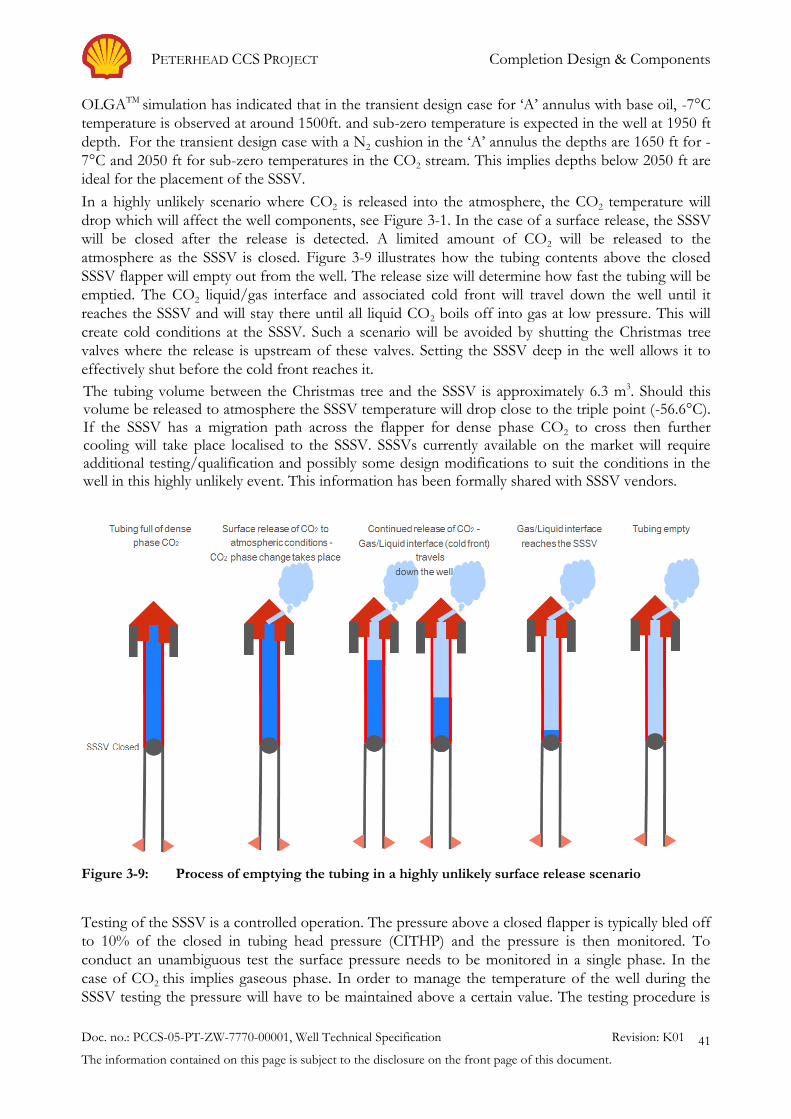
PETERHEAD CCS PROJECT Completion Design & Components
Doc. no.: PCCS-05-PT-ZW-7770-00001, Well Technical Specification Revision: K01
The information contained on this page is subject to the disclosure on the front page of this document.
41
OLGATM simulation has indicated that in the transient design case for ‘A’ annulus with base oil, -7°C
temperature is observed at around 1500ft. and sub-zero temperature is expected in the well at 1950 ft
depth. For the transient design case with a N2 cushion in the ‘A’ annulus the depths are 1650 ft for -
7°C and 2050 ft for sub-zero temperatures in the CO2 stream. This implies depths below 2050 ft are
ideal for the placement of the SSSV.
In a highly unlikely scenario where CO2 is released into the atmosphere, the CO2 temperature will
drop which will affect the well components, see Figure 3-1. In the case of a surface release, the SSSV
will be closed after the release is detected. A limited amount of CO2 will be released to the
atmosphere as the SSSV is closed. Figure 3-9 illustrates how the tubing contents above the closed
SSSV flapper will empty out from the well. The release size will determine how fast the tubing will be
emptied. The CO2 liquid/gas interface and associated cold front will travel down the well until it
reaches the SSSV and will stay there until all liquid CO2 boils off into gas at low pressure. This will
create cold conditions at the SSSV. Such a scenario will be avoided by shutting the Christmas tree
valves where the release is upstream of these valves. Setting the SSSV deep in the well allows it to
effectively shut before the cold front reaches it.
The tubing volume between the Christmas tree and the SSSV is approximately 6.3 m3. Should this volume be released to atmosphere the SSSV temperature will drop close to the triple point (-56.6°C). If the SSSV has a migration path across the flapper for dense phase CO2 to cross then further cooling will take place localised to the SSSV. SSSVs currently available on the market will require additional testing/qualification and possibly some design modifications to suit the conditions in the well in this highly unlikely event. This information has been formally shared with SSSV vendors.
Figure 3-9: Process of emptying the tubing in a highly unlikely surface release scenario
Testing of the SSSV is a controlled operation. The pressure above a closed flapper is typically bled off
to 10% of the closed in tubing head pressure (CITHP) and the pressure is then monitored. To
conduct an unambiguous test the surface pressure needs to be monitored in a single phase. In the
case of CO2 this implies gaseous phase. In order to manage the temperature of the well during the
SSSV testing the pressure will have to be maintained above a certain value. The testing procedure is

PETERHEAD CCS PROJECT Completion Design & Components
Doc. no.: PCCS-05-PT-ZW-7770-00001, Well Technical Specification Revision: K01
The information contained on this page is subject to the disclosure on the front page of this document.
42
predicted to be a lengthy process (approximately 24 hours.). Distributed temperature sensing (DTS)
will be installed as part of the in-well monitoring will assist in this operation and reduce the overall
time required. The procedure for testing the SSSV is detailed in the report Well Operation Guidelines
(6).
To reduce the risk of hydrate deposition it is proposed to displace Methanol as an inhibitor between
the SSSV and the Christmas tree when the well is closed in. The exact volume of Methanol to be
displaced varies with the reservoir pressure and is explained in the Well Operation Guidelines (6).
3.5.1. Hydraulic Control line & Fluid
A ¼" alloy 825 control line will be used to maintain hydraulic pressure on the SSSV. This control line
will be terminated to the SSSV using the vendor’s proprietary connection. The control line will be run
to surface along with the upper completion tubing string. It will be secured to the tubing with cross
coupling protectors installed at every tubing joint, see
Figure 3-10.
The ¼" control line will be encapsulated in 11mm x 11mm protective material such as Teflon or
Tefzel.
It is crucial that the encapsulation material is suitable for the environment in which it will be installed
i.e. Annulus fluid and expected temperatures.
The hydraulic fluid needs to be compatible with all the seals and is required to have suitable thermal
properties i.e. low pour point to ensure that it does not freeze under the low temperature excursions
described in this report.
Figure 3-10: Cross Coupling Protector securing control line to tubing
Production Casing
Tubing
Control Line
Cross Coupling Protector
Coupling (connection between two
tubing joints)

PETERHEAD CCS PROJECT Completion Design & Components
Doc. no.: PCCS-05-PT-ZW-7770-00001, Well Technical Specification Revision: K01
The information contained on this page is subject to the disclosure on the front page of this document.
43
3.6. Production Packer
The production packer has two primary functions, to seal differential pressures effectively and to
anchor the tubing to the casing over a large variety of operating conditions. The packer provides a
barrier in the annulus preventing well bore fluids from interacting with the production casing above
the packer setting depth thereby protecting the casing. A standard 9 5/8" x 3 ½" inch
hydrostatic/hydraulic set production packer made from 13Cr material has been selected, see Figure
3-11. Due to the application an ISO 14310 V0 specification has been applied to the packer. The
packer is placed deep in the well where even under highly unlikely surface release of CO2 scenarios
the CO2 remains in a dense phase and it is hence not subject to low temperature cooling due to JT
effects. The current bottom hole temperature (BHT) is 83°C. The expected temperature during
injection conditions is around 20°C.
It is proposed to use a HNBR (Hydrogenated Nitrile Butadiene Rubber) elastomer-sealing element.
HNBR, also known as “Highly Saturated Nitrile” (HSN), is a special class of nitrile rubber that has
been hydrogenated to increase saturation of the butadiene segment of the carbon polymer backbone.
Improvements to the material properties, over that of a nitrile rubber (NBR), include greater thermal
stability, broader chemical resistance, and greater tensile strength. HNBR can be formulated to meet
application temperatures ranging between -50°C and 165ºC (-58°F-329°F). The element package uses
a three piece multi durometer system consisting of a soft centre and hard end elements. The harder
end elements expand against the packer mandrel and provide an extrusion barrier for the softer
centre element. This provides an effective seal in both high and low pressure applications and casing
Figure 3-11: Production Packer
Note: Figure courtesy of Halliburton
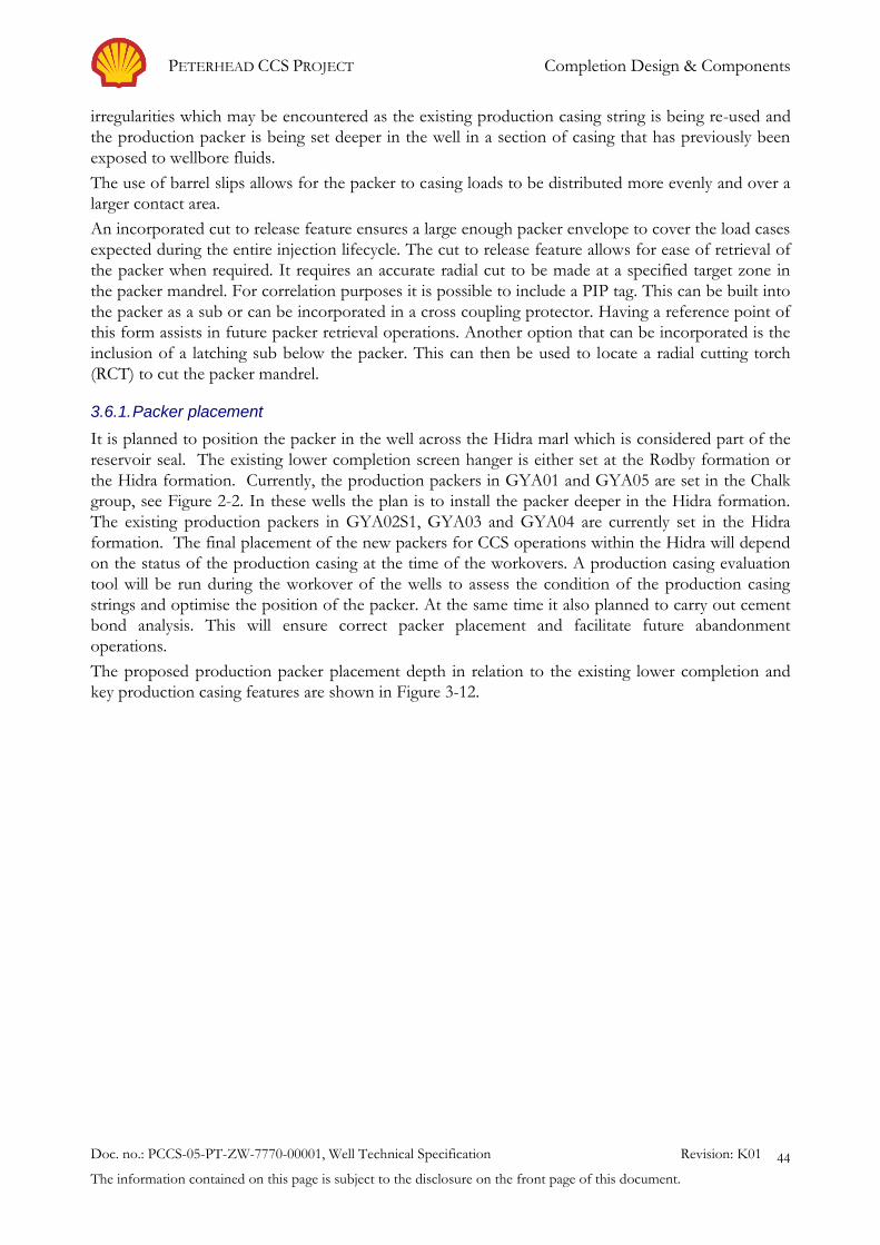
PETERHEAD CCS PROJECT Completion Design & Components
Doc. no.: PCCS-05-PT-ZW-7770-00001, Well Technical Specification Revision: K01
The information contained on this page is subject to the disclosure on the front page of this document.
44
irregularities which may be encountered as the existing production casing string is being re-used and
the production packer is being set deeper in the well in a section of casing that has previously been
exposed to wellbore fluids.
The use of barrel slips allows for the packer to casing loads to be distributed more evenly and over a
larger contact area.
An incorporated cut to release feature ensures a large enough packer envelope to cover the load cases
expected during the entire injection lifecycle. The cut to release feature allows for ease of retrieval of
the packer when required. It requires an accurate radial cut to be made at a specified target zone in
the packer mandrel. For correlation purposes it is possible to include a PIP tag. This can be built into
the packer as a sub or can be incorporated in a cross coupling protector. Having a reference point of
this form assists in future packer retrieval operations. Another option that can be incorporated is the
inclusion of a latching sub below the packer. This can then be used to locate a radial cutting torch
(RCT) to cut the packer mandrel.
3.6.1. Packer placement
It is planned to position the packer in the well across the Hidra marl which is considered part of the
reservoir seal. The existing lower completion screen hanger is either set at the Rødby formation or
the Hidra formation. Currently, the production packers in GYA01 and GYA05 are set in the Chalk
group, see Figure 2-2. In these wells the plan is to install the packer deeper in the Hidra formation.
The existing production packers in GYA02S1, GYA03 and GYA04 are currently set in the Hidra
formation. The final placement of the new packers for CCS operations within the Hidra will depend
on the status of the production casing at the time of the workovers. A production casing evaluation
tool will be run during the workover of the wells to assess the condition of the production casing
strings and optimise the position of the packer. At the same time it also planned to carry out cement
bond analysis. This will ensure correct packer placement and facilitate future abandonment
operations.
The proposed production packer placement depth in relation to the existing lower completion and
key production casing features are shown in Figure 3-12.

PETERHEAD CCS PROJECT Completion Design & Components
Doc. no.: PCCS-05-PT-ZW-7770-00001, Well Technical Specification Revision: K01
The information contained on this page is subject to the disclosure on the front page of this document.
45
Existing Well Scehmatic GYA-01
GYA-01 GYA-02s1 GYA-03 GYA-04 GYA-05
Theoretical Top of Cement 7506 9490 7865 11510 6895
Top Plenus/Hidra Marl 8547 10485 8799 12154 7961
Proposed Packer Setting Depth
(40'-100' above SC-2R packer) 8656 - 8596 10800 - 10740 9050 - 8990 12668 - 12608 8055 - 7995
Cement to Top Plenus/Hidra 109 - 49 315 - 255 251 - 191 514 - 454 94 - 34
SC-2R Packer (screen packer) 8696 10840 9090 12708 8095
Cement to Top Plenus/Hidra 149 355 291 554 134
FIV (cut point) 8755 10900 9150 12768 8155
Cement to Top Plenus/Hidra 208 415 351 614 194
Uniflex 7.00" Liner Hanger 8831 10955 9196 12832 8237
Cement to Top Plenus/Hidra 284 470 397 678 276
9-5/8" Casing Shoe 9006 10990 9365 13010 8395
Cement to Top Plenus/Hidra 459 505 566 856 434
Proposed packer above 9-5/8" Shoe 350 - 410 190 - 250 315 - 375 342 - 402 340 - 400
Injection Wells depths vs Top of Cement (ft.)
Figure 3-12: Proposed production packer placement depth
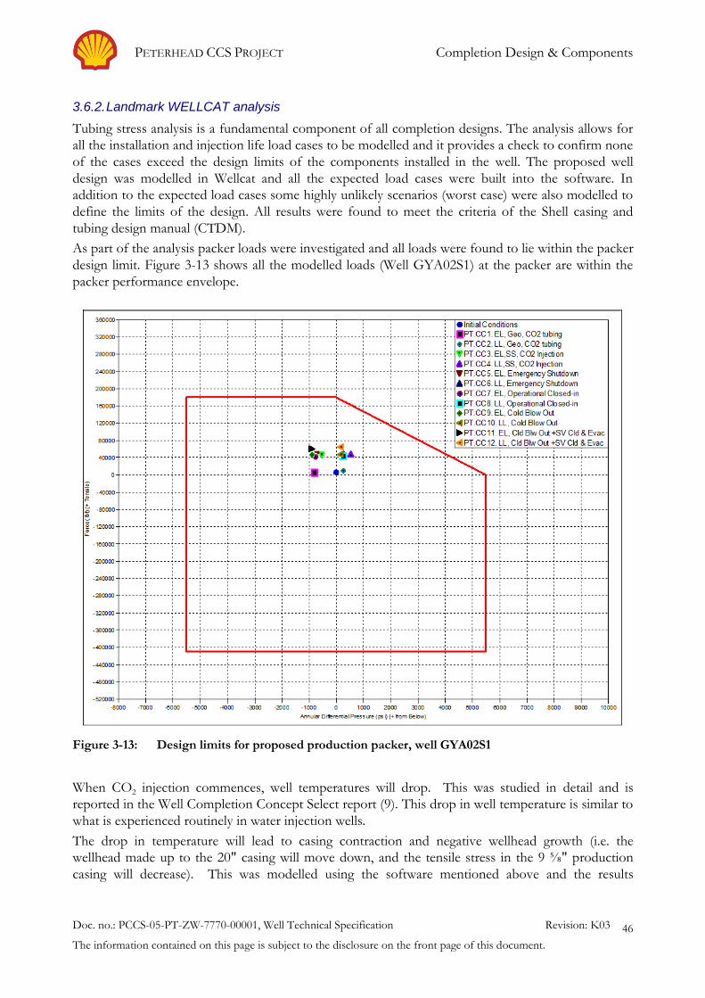
PETERHEAD CCS PROJECT Completion Design & Components
Doc. no.: PCCS-05-PT-ZW-7770-00001, Well Technical Specification Revision: K03
The information contained on this page is subject to the disclosure on the front page of this document.
46
3.6.2. Landmark WELLCAT analysis
Tubing stress analysis is a fundamental component of all completion designs. The analysis allows for
all the installation and injection life load cases to be modelled and it provides a check to confirm none
of the cases exceed the design limits of the components installed in the well. The proposed well
design was modelled in Wellcat and all the expected load cases were built into the software. In
addition to the expected load cases some highly unlikely scenarios (worst case) were also modelled to
define the limits of the design. All results were found to meet the criteria of the Shell casing and
tubing design manual (CTDM).
As part of the analysis packer loads were investigated and all loads were found to lie within the packer
design limit. Figure 3-13 shows all the modelled loads (Well GYA02S1) at the packer are within the
packer performance envelope.
Figure 3-13: Design limits for proposed production packer, well GYA02S1
When CO2 injection commences, well temperatures will drop. This was studied in detail and is
reported in the Well Completion Concept Select report (9). This drop in well temperature is similar to
what is experienced routinely in water injection wells.
The drop in temperature will lead to casing contraction and negative wellhead growth (i.e. the
wellhead made up to the 20" casing will move down, and the tensile stress in the 9 ⅝" production
casing will decrease). This was modelled using the software mentioned above and the results
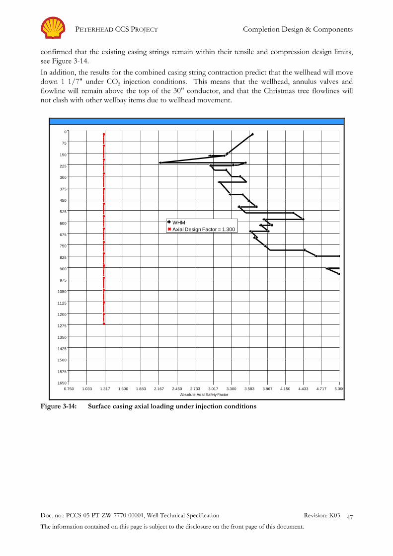
PETERHEAD CCS PROJECT Completion Design & Components
Doc. no.: PCCS-05-PT-ZW-7770-00001, Well Technical Specification Revision: K03
The information contained on this page is subject to the disclosure on the front page of this document.
47
confirmed that the existing casing strings remain within their tensile and compression design limits,
see Figure 3-14.
In addition, the results for the combined casing string contraction predict that the wellhead will move
down 1 1/7" under CO2 injection conditions. This means that the wellhead, annulus valves and
flowline will remain above the top of the 30" conductor, and that the Christmas tree flowlines will
not clash with other wellbay items due to wellhead movement.
Axial Safety Factor - 13 3/8" Surface Casing
0.750 1.033 1.317 1.600 1.883 2.167 2.450 2.733 3.017 3.300 3.583 3.867 4.150 4.433 4.717 5.000
0
75
150
225
300
375
450
525
600
675
750
825
900
975
1050
1125
1200
1275
1350
1425
1500
1575
1650
Absolute Axial Safety Factor
MD
(m
)
WHM
Axial Design Factor = 1.300
Figure 3-14: Surface casing axial loading under injection conditions

PETERHEAD CCS PROJECT Completion Design & Components
Doc. no.: PCCS-05-PT-ZW-7770-00001, Well Technical Specification Revision: K03
The information contained on this page is subject to the disclosure on the front page of this document.
48
3.7. Circulation device
In order to circulate out and replace the A annulus fluid to base oil and to install the required N2 cap
in the A annulus the inclusion of a circulation device in the completion design is essential. A sliding
sleeve (Figure 3-15) run as part of the upper completion tubing string above the production packer
allows for ports to be mechanically opened and closed allowing controlled communication between
the annulus and tubing. Another option available is the inclusion of a gas lift mandrel and valve as
part of the upper completion above the production packer.
The sliding sleeve is designed to perform and maintain seal integrity over repeated cycles. For this
application the intention is to use the device only once at the workover stage. The sliding sleeve uses
a non-elastomeric seal package which provides resistance to down-hole environments. The non-
elastomer seal package comprises PEEK, Teflon and an engineered composite which is chemically
inert and has friction reducing/lubricating qualities and good abrasion resistance. This leads to
increased sealing reliability and reduced shifting forces. The shifting tool provides positive indication
that the sleeve has been shifted. The sleeve design also incorporates a collet lock mechanism that
keeps the sleeve in its required position.
The benefits of the gas lift mandrel and valve option is that it removes the need to run a shifting tool
to open and close the circulating port. The circulation path is created by applying pressure in the
annulus. Designs exist where additional pressure applied to the annulus allows for the gas lift valve to
be locked in the closed position after its use. This helps ensure a leak tight seal is maintained for the
duration of the well life. Gas lift valves with metal to metal seals and ISO 17078 V0 testing (most
stringent testing criteria) are available. The gas lift mandrel unlike the sliding sleeve does not create a
restriction in the tubing and isn’t susceptible to accidental opening during other planned slickline
intervention activities.
Figure 3-15: Sliding Sleeve – Circulation Device

PETERHEAD CCS PROJECT Completion Design & Components
Doc. no.: PCCS-05-PT-ZW-7770-00001, Well Technical Specification Revision: K03
The information contained on this page is subject to the disclosure on the front page of this document.
49
The gas lift mandrel also provides a protected channel for the permanent monitoring control line to
pass across its body. Placement of the control line in this channel keeps the control line away from
the injection ports. A similar arrangement can be requested for the sliding sleeve. This is only
applicable if the monitoring gauges are to be installed below the circulating device.
In addition to the options described above remote operated circulating valves are also available which
allow tubing-annulus communication to be achieved simply by applying tubing pressure. These valves
are again deployed as part of the tubing string above the production packer. Once the packer is set a
pressure signal is sent to the device by tubing pressure application which opens the circulating ports.
Once closed these valves also offer a metal-to-metal V0 rated seal.
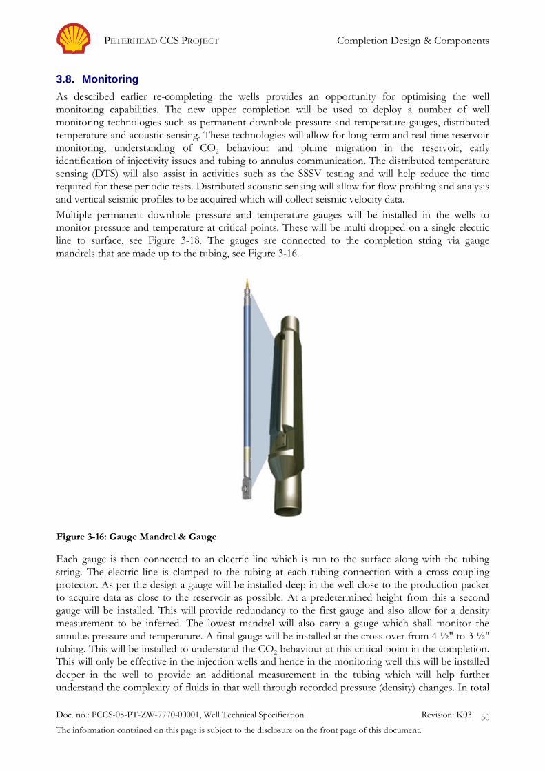
PETERHEAD CCS PROJECT Completion Design & Components
Doc. no.: PCCS-05-PT-ZW-7770-00001, Well Technical Specification Revision: K03
The information contained on this page is subject to the disclosure on the front page of this document.
50
3.8. Monitoring
As described earlier re-completing the wells provides an opportunity for optimising the well
monitoring capabilities. The new upper completion will be used to deploy a number of well
monitoring technologies such as permanent downhole pressure and temperature gauges, distributed
temperature and acoustic sensing. These technologies will allow for long term and real time reservoir
monitoring, understanding of CO2 behaviour and plume migration in the reservoir, early
identification of injectivity issues and tubing to annulus communication. The distributed temperature
sensing (DTS) will also assist in activities such as the SSSV testing and will help reduce the time
required for these periodic tests. Distributed acoustic sensing will allow for flow profiling and analysis
and vertical seismic profiles to be acquired which will collect seismic velocity data.
Multiple permanent downhole pressure and temperature gauges will be installed in the wells to
monitor pressure and temperature at critical points. These will be multi dropped on a single electric
line to surface, see Figure 3-18. The gauges are connected to the completion string via gauge
mandrels that are made up to the tubing, see Figure 3-16.
Each gauge is then connected to an electric line which is run to the surface along with the tubing
string. The electric line is clamped to the tubing at each tubing connection with a cross coupling
protector. As per the design a gauge will be installed deep in the well close to the production packer
to acquire data as close to the reservoir as possible. At a predetermined height from this a second
gauge will be installed. This will provide redundancy to the first gauge and also allow for a density
measurement to be inferred. The lowest mandrel will also carry a gauge which shall monitor the
annulus pressure and temperature. A final gauge will be installed at the cross over from 4 ½" to 3 ½"
tubing. This will be installed to understand the CO2 behaviour at this critical point in the completion.
This will only be effective in the injection wells and hence in the monitoring well this will be installed
deeper in the well to provide an additional measurement in the tubing which will help further
understand the complexity of fluids in that well through recorded pressure (density) changes. In total
Figure 3-16: Gauge Mandrel & Gauge
PETERHEAD CCS PROJECT Completion Design & Components
Doc. no.: PCCS-05-PT-ZW-7770-00001, Well Technical Specification Revision: K03
The information contained on this page is subject to the disclosure on the front page of this document.
51
4 permanent downhole gauges will be installed per well, 3 monitoring the pressure and temperature in
the tubing and 1 measuring the pressure and temperature in the annulus. Deployment of such
systems is standard practice within the North Sea and extensive knowledge of this exists within Shell
UK. There is an option for reducing the number of gauges in wells GYA04 as this well is planned to
be put on injection later in the project by which time the project would have collected sufficient
amount of data to understand the CO2 behaviour in the tubing removing the need for the x-over
gauge.
Pressure and temperature modelling suggests that the bottom hole Temperature (BHT) is likely to be
in the region of 17°C-35°C [63°F - 95°F]. Currently pressure and temperature gauges are routinely
calibrated for temperatures in the range 25°C-150°C [65°F-302°F]. Therefore further qualification of
the system will be required before it can be utilised on Goldeneye for CCS operations.
In addition to the single point pressure and temperature sensors described above distributed
temperature sensing (DTS) will be installed in the wells. This will provide a temperature profile along
the entire path of the well from surface to close to the production packer. In order to deploy DTS a
fibre optic line will be run along with the electric line. This may be bundled together with the electric
line in a single encapsulated control line or it may be deployed as an independent ¼" line with
multiple fibre lines for redundancy. The DTS will assist in understanding the behaviour of CO2 in the
well, during transient conditions (opening and closing the well and SSSV inflow testing) the
temperature profile will assist in operations and also help reduce the time for some of these
operations. In the unlikely event of a tubing leak, the distributed temperature readings would facilitate
the location of the leak. DTS will also help identify the position of a gas/liquid interface (Figure 3-9)
in the well and follow its movement down the well.
Distributed acoustic sensing (DAS) will also be incorporated within the monitoring package. Similar
to the DTS system this involves running an additional fibre optic line to surface. Again this line may
be bundled with the electric line or may be run as a separate ¼" line with the DTS and DAS fibre
lines combined. Having DAS installed in the well is similar to having acoustic receivers stationed
along the wellbore and as such it allows for periodic vertical seismic profiles (VSP) to be acquired.
Using DAS for this technique provides excellent coverage along the entire length of the well. The
sensitivity of the system is not as good as having dedicated geophones in the well and with DAS
some of the directionality is also lost. The technology is still in its early stages and improvements are
being made. With these improvements the sensitivity is also increasing and DAS may also be used for
monitoring seismicity.
The control lines (¼" tube) are fed through the tubing hanger and exit the wellhead through a
dedicated wellhead outlet. If a combined electric and fibre optic control line is deployed then a hybrid
well head outlet will be installed at surface where the electrical and fibre optic lines are split and
connected to the surface lines to the control room where the respective surface acquisitions units will
be placed, see Figure 3-17.
If separate electric and fibre optic control lines are deployed then two ports will be required in the
tubing hanger for the monitoring system and two wellhead outlets will be required at surface, one
electrical wellhead outlet and one optical wellhead outlet.

PETERHEAD CCS PROJECT Completion Design & Components
Doc. no.: PCCS-05-PT-ZW-7770-00001, Well Technical Specification Revision: K03
The information contained on this page is subject to the disclosure on the front page of this document.
52
Figure 3-17: Hybrid Wellhead Outlet
Note: Figure courtesy of Schlumberger
As part of the topside refit new cables will be laid between the wellhead area and the control room. In
addition to the standard electrical lines this surface cabling will also incorporate fibre optic lines for
the DTS and DAS communication with the surface acquisition units. A summary of information on
the surface units (space required, bandwidth requirement for data transmission and power
requirements) is provided in the Well and Reservoir Management Plan (4).
Data from the permanent down hole pressure and temperature gauges will be available live through
the PI server. DTS data is considered critical during transient operations such as well start up and
activities like SSSV inflow testing during these periods of interest the DTS data will be made
available. Due to the high number of data points available in DTS (spacial resolution can be set to as
low at every half meter) it is not planned to have all the data available in PI. The data will therefore
bypass the platform distributed control system (DCS). This reduces the number of PI data tags
required. The optimal methodology to manage and transfer this data is currently under review and
will be developed in the next project phase.
Due to the large volume of data generated by DAS the data will be retrieved as and when required,
some of the data computing for DAS may also be carried out in the control room to reduce the
amount of data that is required to be transmitted. The actual DAS data may then be retrieved from
the rig and hand carried onshore if required. These measures allow the total bandwidth requirement
to be limited.
Requalification of the in-well components to maintain integrity in potential low temperatures and to
withstand the cold front (gas/liquid interface) will be required prior to deployment. The worst case
conditions have been shared with vendors and the vendors have been engaged to develop a timeline
for the necessary qualification/testing.

PETERHEAD CCS PROJECT Completion Design & Components
Doc. no.: PCCS-05-PT-ZW-7770-00001, Well Technical Specification Revision: K03
The information contained on this page is subject to the disclosure on the front page of this document.
53
Figure 3-18: Hybrid Cable – Combined Electrical and Fiber Optic Line [from Schlumberger]
Note: Figure courtesy of Schlumberger
PETERHEAD CCS PROJECT Completion Design & Components
Doc. no.: PCCS-05-PT-ZW-7770-00001, Well Technical Specification Revision: K03
The information contained on this page is subject to the disclosure on the front page of this document.
54
3.9. Lower Completion
The lower completion consists of a gravel pack including 4" premium screens set inside a 7" pre-
drilled liner across the reservoir. The current wells were drilled only in the top 60 ft - 70 ft [18.3-
21.3m] (vertical depth) of the main reservoir - Captain D. See Figure 2-2, and Figure 2-4.
The lower completion comprises of 13Cr steel. This is valid for the 4'' Screens and 7'' Pre-perforated
liner. To avoid expensive side-tracks it is recommended to control the Oxygen in the injection fluid
to acceptable levels. This has been calculated at 1 ppm Oxygen in the CO2 stream.
From the analysis to date, there is no reason to sidetrack the wells to install a new lower completion
and hence the lower completion will not be changed during the workover operations. There are
some operational restrictions related to the characteristics of the CO2 and some limitations related to
the size of particles in the injected CO2. Based on the productivity during the hydrocarbon
production phase it is not required to stimulate the wells for the CO2 injection. A detailed review of
the lower completion is included in the Conceptual Completion and Well Intervention Design
Endorsement Report (1).
Plugging
Plugging will reduce the injectivity through the screens and gravel with time. Under injection any
particles bigger than a critical size will start to accumulate internally at the screens, smaller solids can
pass the screens but may accumulate in the gravel; even smaller solids may travel through the gravel.
Due to the possible presence of solids in the injection stream filtration of the CO2 is required. The
internal volume of the screens across the Captain D reservoir is very small, from 0.31 m3 to 0.55 m3
(1.9 bbl - 3.4 bbl.) (depending on the well). There is no allowance for accumulation of solids inside
the screens. It is therefore recommended to carry out filtration to 17 micron to avoid the plugging of
the lower completion; more stringent filtration to 5 microns is required to avoid the plugging of the
formation. A 5 micron filtration system with redundancy is planned to be installed on the platform
during the topside construction phase.
Erosion
Erosion is one of the most common mechanisms of screen failure. Screen erosion is a progressive
failure that depends on fluid velocity, particle size and concentration and fluid properties. Erosion of
the screen can be caused by the high downhole flow of fluid through the screens. The presence of
solids will increase the erosion rate. The use of filtration methods described above reduces the
potential for erosion.
During the injection process the CO2 will contact the screens before the gravel and as such the
restrictions for stand-alone screens (SAS) related to erosion should be applied (instead of the gravel
pack restrictions). Liquid limitations (instead of gas limitations) should be used as the density of the
CO2 at bottom hole injection conditions will be very high ~920-940 kg/m3. For liquid flow the
normally accepted industry velocity is 1 ft/s [0.3m/s] for production conditions.
In order to avoid high downhole injection rates during injection start-up it is recommended to start-
up the injection over a 30-60 minute interval. This is explained in the Well Completion Concept
Select report (9).
Hydrates
The formation of hydrates is only possible when water is present in sufficiently significant quantities
and the temperature and pressure of the fluid is within the hydrate formation window.
During hydrocarbon production, water encroached into the Goldeneye gas cap and at least part of
the lower completion will be surrounded by water at the time that CO2 injection commences. The
trapped gas saturation is estimated to be 25%, so some methane will remain near the well. The
methane is miscible with CO2 and consequently will eventually be displaced by the injected CO2. The

PETERHEAD CCS PROJECT Completion Design & Components
Doc. no.: PCCS-05-PT-ZW-7770-00001, Well Technical Specification Revision: K03
The information contained on this page is subject to the disclosure on the front page of this document.
55
initial injection of CO2 will drive water away from a well and cool the reservoir. The cooling of the
injection well and the surrounding reservoir matrix will create conditions favourable for the
formation of hydrates.
In order to reduce the risk of hydrate formation during the first years of injection (once water is
displaced from the wellbore) it is required introduce batch hydrate inhibition prior to injection start-
up. If water is subsequently introduced into a well and/or it is suspected that water is present in a
wellbore, then batch injection should continue. Methanol is currently preferred as an inhibitor. Batch
hydrate inhibition features as an instruction in the well operational procedures included in the Well
Operation Guidelines (6).
3.10. Fluid Selection
In order to workover the wells it is required that the wells are first “killed” (operation of placing a
column of heavy fluid into as well bore to prevent the flow of reservoir fluids) and the reservoir
isolated; the workover carried out; and then the recompleted well put “on injection”. These stages of
well construction are discussed in Section 0 Constructability. At each of these stages there are
different fluid requirements in the well.
Prior to working over the wells reservoir isolation will be required. For this it is possible that a fluid
based pill might be used with a fluid column above the pill to maintain a hydrostatic pressure
overbalance. During the well clean out operation prior to running the new upper completion there is
a requirement for clean-up fluids and circulation fluids, these are discussed in section 4.3.
The completion fluid and packer fluid options and selection criteria are discussed here.
3.10.1. Completion Fluid
Once all workover operations have been carried out, the tubing hanger and tree will be installed and
pressure tested. This will then allow for final well hook up and flow of CO2 through the pipeline to
the platform. The completion fluid left in the tubing will be compatible with the well components
and with the formation. Additionally, the fluid will help minimise the JT effect caused by expansion
of CO2.
From the injectivity perspective it is preferred to have water or gas, rather than base oil or diesel to
avoid the introduction of a new phase in the wellbore, which might affect the relative permeability to
CO2. However, the volume of base oil to be displaced by the CO2 is small and the CO2 will fully
displace the base oil around the wellbore due to its predicted miscibility. Additionally, there will be
enough injection pressure available during the initial stage of injection to overcome any relative
permeability effects.
The ideal case is to have a fluid in the tubing which will lead to a wellhead (WH) pressure in the order
of 35 bara to 70 bara. Under this scenario, the JT cooling will be minimal during initial start-up
operations. In the case of a single fluid in the tubing which gives a WH pressure of 35 bara at 196.5
bara bottom hole pressure, the required fluid column density is 0.283 psi/ft [0.064bar/m]. This will
however lead to difficulties of running the completion in an underbalanced well.
In the case of having water in the tubing, the WH pressure will be close to atmospheric pressure. In
this scenario at CO2 injection start up the CO2 will flash and JT cooling effect will prevail.
In the case of base oil (pressure gradient of 0.35 psi/ft) the hydrostatic pressure exerted by the base
oil will be in the order of 2860 psia [197 bara] at reservoir level. This pressure is not sufficient for well
control.
The current design plan is to carry out workovers in inhibited seawater. This fluid is compatible with
the completion equipment. The expected WH pressure is around atmospheric due to the fluid

PETERHEAD CCS PROJECT Completion Design & Components
Doc. no.: PCCS-05-PT-ZW-7770-00001, Well Technical Specification Revision: K03
The information contained on this page is subject to the disclosure on the front page of this document.
56
column weight and the low reservoir pressure. Prior to injecting CO2 it is therefore necessary to
install a N2 cushion in the top of the well to increase the tubing WH pressure to 35 bara in order to
reduce the JT effect during the initial injection.
The true vertical length of the N2 cushion in order to obtain 35 bara (500 psia) in the top of the well
assuming water of 0.44 psi/ft gradient below the N2 and 2850 psia reservoir pressure is estimated at
around 2900ft. The initial well start-up process is described in the Well Operation Guidelines (6).
3.10.2. Packer Fluid
During transient operations (close-in and start-up operations), a temperature drop is observed at the
top of the well for a short period of time. The faster the shut-in or faster the well opening operation,
the less the resultant temperature drop. The cooling effect diminishes deeper into the well due to
limited CO2 flashing and heat transfer from surrounding wellbore, see Figure 3-2. As a result of this
the annulus fluid in the top of the well will also see a reduction in temperature. This forms a key
factor in the annulus fluid selection.
The fluid left in the A annulus for Goldeneye Wells will have the following characteristics:
Avoid/minimise corrosion of the tubing and production casing.
The rheological properties of the packer fluid will be stable during injection period.
It will have a low freezing point to cope with the well transient conditions and will be stable
in terms of phase envelope.
The fluid will be solids free.
It will allow for a positive pressure to be maintained at all times which will assist in
monitoring of the annulus.
After running the completion and setting the production packer the annulus fluid will be replaced
with Base oil. The advantages of base oil over a water based fluid are described in Table 3-5.

PETERHEAD CCS PROJECT Completion Design & Components
Doc. no.: PCCS-05-PT-ZW-7770-00001, Well Technical Specification Revision: K03
The information contained on this page is subject to the disclosure on the front page of this document.
57
Table 3-5: Comparison between base oil and water based fluid in the A annulus.
Base Oil Water based fluid
Corrosion Management No corrosion (if no water
present)
Depends on injection time and
place of the tubing leak
Corrosion in the casing (CS) in the
case of CO2 tubing leak (water
present in the A-annulus)
1year allowance
Thermal expansion High ~186 psi/°C
For average 30°C temp. change
Change in pressure ~5560 psia
Or Change in height ~225-
330 ft (well)
Medium ~62 psi/°C
For average 30°C temp. change
Change in pressure ~1850psia
Or Change in height ~54-80 ft (well)
Freezing point Can be tailored to the required
temperature (e.g. -11°C or -
60°C)
Freezing Temperature
Seawater ~-1.8°C
Theoretical Min. freezing depression
temperature (saturated brine):
NaCl -21°C, KCl -9.5°C, CaCl2 -45°C
CO2 injection aspects No difference
Steady State ~1-4°C top
Transient ~-20°C fluid, -11°C A
annulus for a short period of
time
No difference
The expected A-annulus surface temperature with water based fluid during transient condition is
approximately -11°C. Fresh water will freeze at this start-up A-annulus temperature. Seawater will
freeze around -1.8°C. If possible, water should be avoided in the well due to formation of carbonic
acid and formation of hydrates. In the case of leak there will be limited time to avoid corrosion of
the production casing made of carbon steel. Oil based packer fluid will help to avoid/minimise
corrosion in the tubing and production casing.
The main concern with base oil as packer fluid is the high thermal expansion/contraction
(~180 psi/°C) with respect to water base fluids (~60 psi/°C). For an annulus filled with base oil
frequent platform visits would be required to manage the expansion/contraction of the base oil
column by topping up during the injection period and bleeding off during the closed in period if a
positive pressure is required to be maintained in the A annulus. The proposed solution is the
installation of a compressible fluid in the top of the annulus. The benefits of installing a N2 cushion
in the A annulus are outlined in Table 3-6.

PETERHEAD CCS PROJECT Completion Design & Components
Doc. no.: PCCS-05-PT-ZW-7770-00001, Well Technical Specification Revision: K03
The information contained on this page is subject to the disclosure on the front page of this document.
58
Table 3-6: Benefits of installing a N2 cushion in the A annulus.
A annulus with N2 cushion A annulus Without N2 cushion
Initial
conditions
N2 cushion: 300 psia, 300 ft of N2 Positive pressure 150-300 psia
Base oil to top of the well
Thermal
contraction
(from
geothermal to
injection)
Low - Compressible fluid in the top
Fluid interface deeper + pressure
reduction (more vol. and lower T for
the N2)
+ve pressure maintained. ~140 psia
after cooling
N2 Level down to 525-630 ft
Top of the well to vacuum
No +ve pressure maintained
Change in height ~225-330 ft (well)
To keep +ve positive pressure then
~16.5 - 24 bbl of fluid to be topped-up
Thermal
expansion
(from
injection to
geothermal)
Low
N2 level rise and pressure increase
To ~installation (300 psia, 300 ft N2
level)
If the well is topped up during the
injection (and level at the tree).
Change in pressure ~5560 psia due to
thermal effects
CO2 injection
aspects
Steady State ~1-4°C top same
Transient (short time): -22°C CO2,
-22°C tubing, -6°C A annulus
Steady State ~1-4°C top
Transient (short time): -20°C CO2,
-15°C tubing, -11°C A annulus
Well Integrity OK Pressure above casing burst pressure of
the production casing (8150 psia for
9 5/8" 53# L80), equivalent to a surface
pressure of ~5000 psia for 8150 ft TVD
and 0.375 psi/ft base oil gradient.
Well
Operations
Keep minimum ~60 psia at geothermal
conditions (to keep +ve pressure
during injection).
Echometer to know N2-fluid level
Frequent platform trips. Topping Up
or bleeding off fluid in the annulus for
keeping positive pressure.
With a N2 cushion installed the 4 ½" tubing will get colder by a couple of degree centigrade due to
the insulation properties of the N2. The tubing will be at the same temperature as the injection CO2;
this does not pose a threat as it is planned to install S13Cr tubing in the top part of the well. The “A”
annulus fluid and production casings will remain warmer which is another positive effect of installing
the N2 cushion.
The packer fluid placement technique will require review pre execution as part of the detailed well
completion programme.

PETERHEAD CCS PROJECT Constructability
Doc. no.: PCCS-05-PT-ZW-7770-00001, Well Technical Specification Revision: K03
The information contained on this page is subject to the disclosure on the front page of this document.
59
4. Constructability
A heavy-duty jack up is required for the workover activities due to the 400 ft [122m] this is not the
water depth at the platform but more likely to be the height of the X-mas tree above the sea bed
(which is key for a jack up rig) water depth. There are only a small number of jackups worldwide that
can work in the water depth at Goldeneye location.
The wells will be worked over by establishing a downhole barrier to plug the well. The existing
production packer and completion will be removed. A new packer will be installed along with the
tubing and a tail pipe assembly stabbed into the top of the existing sand screen packer. An outline
programme is presented below:
Rig to location.
Kill Well / set downhole barriers.
Remove Christmas tree.
Rig up & test BOP’s (Blow Out Preventers).
Recover downhole barriers.
Recover existing completion tubing.
Recover packer.
Clean scrape 9 5/8" [245mm] casing.
Carry out cement logging.
Run new completion tubing.
Set packer.
Test tubing, annulus and SSSV.
Install and test Christmas tree.
4.1. Reservoir isolation
In order to perform a work over and replace the existing upper completion the integrity of the well
has to be managed in order to protect the surroundings from any remaining hydrocarbons in the well.
This includes ensuring two effective barriers are in place. Selecting a suitable means to isolate the
reservoir during the work over is a challenge due to the restrictions imposed by the internal diameter
(ID) of the new proposed upper completion.
The existing upper completion has a 4.47" [113.5mm] minimum ID restriction at the mule shoe. The
plug has to travel through the current completion (minimum restriction 4.47") and set in either a 5"
tubing section (15 lb/ft weight [20.34Nm], 4.408" ID) or a 7" tubing section (29 lb/ft weight, 6.184"
ID). The preferred and most likely position for the barrier is in the 5" section since it is more feasible
to set a barrier in 5" that can travel though the current 5.5" completion.
See existing well schematic in Error! Reference source not found.. A list of equipment installed in
the lower completion (in hole tally) is provided in Table 2-4.
The plug has to be recovered through the proposed upper completion (2.787" tubing drift) or left in
the lower completion. If left in the well it must have an ID larger then than 2" to allow tools to pass
for future interventions.
There are some other factors that have to be considered when sourcing a suitable plug for the well.
The ability of the plug to hold the required differential pressure. The 5" setting section is only 10ft
long (made up of two 5 ft pup joints). Below the 5" section there is a Formation Isolation Valve
(FIV) with a restriction of 2.94" at the top, again restricting the setting length to 10 ft. The condition
of this 5" section is also unknown.

PETERHEAD CCS PROJECT Constructability
Doc. no.: PCCS-05-PT-ZW-7770-00001, Well Technical Specification Revision: K03
The information contained on this page is subject to the disclosure on the front page of this document.
60
Another key consideration when reviewing the barrier options was to avoid interference with the
existing lower completion in order to maintain integrity for maximum injectivity. The lower
completion will be left in place and it will form part of the completion design for CO2 injection. The
lower completion of the wells consists of open hole gravel packs including premium screens and pre-
drilled liners. These screens have a minimum ID of 3.548". The Sump at the bottom of the well is 3 ft
in length. These factors limit pushing anything down hole as an alternative to retrieving it, mainly due
to the small sump size and risk of damaging or blocking the screens (reducing injectivity) but also
because it is unlikely to be able to pass though the 2.94" FIV restriction.
Another important consideration is around the gravel pack sleeve below the existing sand control
packer. All the plug devices discussed rely on sealing in the tubing below this sleeve. If the sleeve is
leaking it will be hard to identify the source of the leak.
As well as the feasibility of suitable barriers other important factors must be considered such as; complying with industry and Shell standards, possible cost of development; the cost of the barrier itself and HSSE. A study was carried out to review the plugs available in the market and a range of possible solutions were explored. These solutions included mechanical plugs, inflatable plugs, utilising the existing formation isolation valve in the lower completion, disappearing plugs and fluid based pills such as cross linked polymers with breakers.
The FIV installed in the lower completion is a ball valve that was last actuated at the time of the
original well completions i.e. 2004. The valve has been installed in the well for over 10 years and its
current condition is unknown. The well is unlikely to be scaled and it did not produce any sand
therefore it is possible that the valve could be an effective barrier.
Fluid based solutions such as solids free loss pill with internal breakers capable of reducing the
viscosity over a set period of time and internal screen pills utilising sized calcium carbonate to bridge
of inside the screens with a subsequent acid breaker have been proposed. These solutions require
further engagement with the vendors to formulate the required pill. Modelling is required to
understand the interaction with the gravel pack and the formation. Core flood testing is required to
confirm fluid stability and any resultant formation damage (reduction of permeability around the
wellbore which is the consequence of drilling, completion, injection, chemical treatment, attempted
stimulation or production of that well).
The use of a tubing deployed remote operated plug in conjunction with a fluid barrier offers
advantages in reduced wireline trips with high reliability. For example remote operated plugs can be
deployed below the production packer as part of the tubing string. This plug can be repeatedly
opened or closed by remote command and can be used to set the production packer and pressure test
the tubing string.
A number of mechanical plug options have been evaluated and proposals have been received from
the respective vendors. The solutions either involve a retrievable solution or a disappearing plug
(glass/magnesium alloys) deployed on a lock/packer type device. All the proposed solutions require
some development work from design modifications and size scaling to re-qualification. The required
design modifications, retesting and qualification is achievable in the given timeframe. Suitable
inflatable plugs have been identified that can be retrieved through the proposed upper completion.
The use of such a plug would have to be adequately risk assessed and reviewed by an independent
competent person (technical authority) before each application.
The development work around the reservoir isolation plug will require to be closely monitored and
the selected components adequately tested and qualified. For this the Shell Completion and
Intervention Equipment Qualification team (CERT/IERT) and QA/QC teams will be engaged.
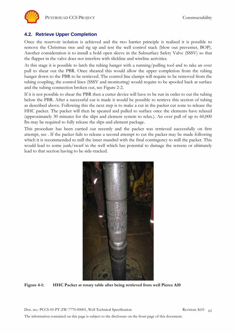
PETERHEAD CCS PROJECT Constructability
Doc. no.: PCCS-05-PT-ZW-7770-00001, Well Technical Specification Revision: K03
The information contained on this page is subject to the disclosure on the front page of this document.
61
4.2. Retrieve Upper Completion
Once the reservoir isolation is achieved and the two barrier principle is realised it is possible to
remove the Christmas tree and rig up and test the well control stack (blow out preventer, BOP).
Another consideration is to install a hold open sleeve in the Subsurface Safety Valve (SSSV) so that
the flapper in the valve does not interfere with slickline and wireline activities.
At this stage it is possible to latch the tubing hanger with a running/pulling tool and to take an over
pull to shear out the PBR. Once sheared this would allow the upper completion from the tubing
hanger down to the PBR to be retrieved. The control line clamps will require to be removed from the
tubing coupling, the control lines (SSSV and monitoring) would require to be spooled back at surface
and the tubing connection broken out, see Figure 2-2.
If it is not possible to shear the PBR then a cutter device will have to be run in order to cut the tubing
below the PBR. After a successful cut is made it would be possible to retrieve this section of tubing
as described above. Following this the next step is to make a cut in the packer cut zone to release the
HHC packer. The packer will then be speared and pulled to surface once the elements have relaxed
(approximately 30 minutes for the slips and element system to relax.). An over pull of up to 60,000
lbs may be required to fully release the slips and element package.
This procedure has been carried out recently and the packer was retrieved successfully on first
attempt, see . If the packer fails to release a second attempt to cut the packer may be made following
which it is recommended to mill the inner mandrel with the final contingency to mill the packer. This
would lead to some junk/swarf in the well which has potential to damage the screens or ultimately
lead to that section having to be side-tracked.
Figure 4-1: HHC Packer at rotary table after being retrieved from well Pierce A10

PETERHEAD CCS PROJECT Constructability
Doc. no.: PCCS-05-PT-ZW-7770-00001, Well Technical Specification Revision: K03
The information contained on this page is subject to the disclosure on the front page of this document.
62
It is essential that after retrieving the packer and tailpipe a robust clean up procedure is followed in
order to clean-up the wellbore and remove any debris from the well prior to running the new
completion. This requirement is heightened by the presence of any mechanical plug (e.g. FIV) that
may be affected by the debris in the well.
It is also the intention to run cement bond logs and ultrasonic imaging tools to evaluate the annular
cement placement and quality. At the same time casing calliper evaluation tools will be run in order to
determine the exact placement depth of the new production packer.

PETERHEAD CCS PROJECT Constructability
Doc. no.: PCCS-05-PT-ZW-7770-00001, Well Technical Specification Revision: K03
The information contained on this page is subject to the disclosure on the front page of this document.
63
4.3. Wellbore Clean Out
Having retrieved the existing upper completion in order to remove all debris from the well, avoid
formation damage and prepare the well for installation of the new completion string a wellbore clean
out operation is planned. As highlighted in the section above it is critical that a good wellbore clean
out is achieved and filtered fluid is left in the well for the new upper completion to be run in.
The clean out string incorporates mechanical tools, hydraulics and specialist chemicals. The
mechanical wellbore clean up tools will scrape and prepare the 9 5/8" casing for receiving the new
completion and isolate the lower completion from losses during clean out operations. It is intended
to set the new production packer deeper in the well in a section of casing that has been unprotected
during the production life and while the wells have been left suspended. The scraper tool will be run
across this section of casing and down to the existing sand control packer circulating at the maximum
allowed rate. Any debris dislodged by this action can be flushed to surface or caught in a junk catcher
sub included in the string. Some metallic debris can be captured with magnetic subs. If a junk catcher
sub is retrieved to surface and it is full this is an indication that the clean out string should be re-run.
The clean-out string will include a temporary packer which allows the casing to be pressure tested
against. Once the casing is tested clean up pills can be pumped. The pills are finally chased with clean
inhibited seawater (inhibition recipe to include biocide, oxygen scavenger and corrosion inhibitor)
until the required clean-up criteria is achieved usually measured in percentage of solids by volume.
Table 4-1 provides a list of clean out fluids, volumes and proposed circulation rates.
Table 4-1: Proposed wellbore clean out pills and fluids.
No. Fluid Type Volume (bbls) Pump Rate
(bbls/min)
1 Pill A - 10% Surfactant “Wash Pill” 120 As dictated by any
losses seen
2 Pill B - Hi-Vis 5% Surfactant “Catch Pill 60 As dictated by any
losses seen
3 Clean Inhibited Filtered Seawater (to place
pills 500 ft above MFCT in annulus)
As required As dictated by any
losses seen
4 Clean Inhibited Filtered Seawater (to achieve
clean out criteria)
As required 15-20
A separate clean out trip is planned to jet the wellhead and BOP as these are areas where debris tends
to accumulate.
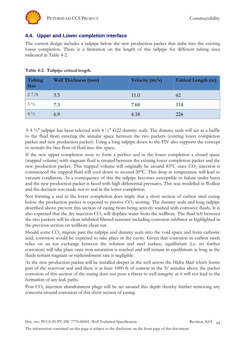
PETERHEAD CCS PROJECT Constructability
Doc. no.: PCCS-05-PT-ZW-7770-00001, Well Technical Specification Revision: K03
The information contained on this page is subject to the disclosure on the front page of this document.
64
4.4. Upper and Lower completion interface
The current design includes a tailpipe below the new production packer that stabs into the existing
lower completion. There is a limitation on the length of this tailpipe for different tubing sizes
indicated in Table 4-2.
Table 4-2: Tailpipe critical length.
Tubing
Size
Wall Thickness (mm) Velocity (m/s) Critical Length (m)
2 7/8 5.5 11.0 62
3 ½ 7.3 7.68 114
4 ½ 6.9 4.18 226
A 4 ½" tailpipe has been selected with 4 ½" G22 dummy seals. The dummy seals will act as a baffle
to the fluid from entering the annular space between the two packers (existing lower completion
packer and new production packer). Using a long tailpipe down to the FIV also supports the concept
to restrain the free flow of fluid into this space.
If the new upper completion were to form a perfect seal in the lower completion a closed space
(trapped volume) with stagnant fluid is created between the existing lower completion packer and the
new production packer. This trapped volume will originally be around 83°C once CO2 injection is
commenced the trapped fluid will cool down to around 20°C. This drop in temperature will lead to
vacuum conditions. As a consequence of this the tailpipe becomes susceptible to failure under burst
and the new production packer is faced with high differential pressures. This was modelled in Wellcat
and the decision was made not to seal in the lower completion.
Not forming a seal in the lower completion does imply that a short section of carbon steel casing
below the production packer is exposed to passive CO2 wetting. The dummy seals and long tailpipe
described above prevent this section of casing from being actively washed with corrosive fluids. It is
also expected that the dry injection CO2 will displace water from the wellbore. The fluid left between
the two packers will be clean inhibited filtered seawater including corrosion inhibitor as highlighted in
the previous section on wellbore clean out.
Should some CO2 migrate past the tailpipe and dummy seals into the void space and form carbonic
acid, corrosion would be expected to take place in the cavity. Given that corrosion in carbon steels
relies on an ion exchange between the solution and steel surface, equilibrium (i.e. no further
corrosion) will take place once iron saturation is reached and will remain in equilibrium as long as the
fluids remain stagnant or replenishment rate is negligible.
As the new production packer will be installed deeper in the well across the Hidra Marl which forms
part of the reservoir seal and there is at least 1000 ft of cement in the ‘b’ annulus above the packer
corrosion of this section of the casing does not pose a threat to well integrity as it will not lead to the
formation of any leak paths.
Post CO2 injection abandonment plugs will be set around this depth thereby further removing any
concerns around corrosion of this short section of casing.

PETERHEAD CCS PROJECT Constructability
Doc. no.: PCCS-05-PT-ZW-7770-00001, Well Technical Specification Revision: K03
The information contained on this page is subject to the disclosure on the front page of this document.
65
4.5. Future Well Abandonment
Upon cessation of CO2 injection, the Goldeneye injection wells will be permanently abandoned. The
abandonments will be based on the following conceptual basis of design:
The Captain and Balmoral formations are the zones which will require isolation during
abandonment.
The abandonment design currently complies with the latest industry standards and Oil &
Gas UK, “Guidelines for the Suspension and Abandonment of Wells”
However, at the time of abandonment, the designs will be updated to comply with the
prevailing legislative or industry standards.
The Captain reservoir will be abandoned by setting two cement plugs opposite the
Plenus/Hidra Marl and Rødby Shale.
Where sufficient formation length exists, the two cement plugs will be set as a single
combination plug.
In all cases, the upper completion production packer will be removed prior to setting the
abandonment plugs for plug length purposes.
If required for plug length, the lower completion screen hanger and tubulars down to the
FIV will be removed prior to setting the abandonment plugs.
Cement bond logs will be run in each 9 ⅝" casing string to determine the position of top of
cement behind the casing, and to evaluate cement quality.
The expectation is that top of cement and cement quality will be acceptable, and if this
is confirmed, then the abandonments will be conducted by setting cement plugs inside
the 9 ⅝" casing and opposite logged cement.
In the event that either top of cement and cement quality are deemed to be
unacceptable following log evaluation, the Captain reservoir will be abandoned by
section milling a window in the 9 ⅝" casing opposite the Plenus/Hidra Marl and Rødby
Shale and setting a “rock-to-rock” cement plug across the window. The abandonment
plug set across the Lista will provide the secondary barrier to the 9 ⅝" casing annulus in
this case.
The Balmoral formation will be abandoned using a single cement plug, unless it is suspected
that CO2 has leaked into this formation.
If leakage is suspected, the Balmoral formation will be abandoned using two cement
plugs.
It is currently planned to use conventional cements with additives to maintain elasticity.
However, at the time of abandonment, cement slurry design will be re-evaluated to ensure
that any new products developed in the intervening period are incorporated into the
abandonment plug design.
The proposed abandonment concepts are discussed in the report Abandonment Concept for
Injection Wells (8).

PETERHEAD CCS PROJECT Well Intervention
Doc. no.: PCCS-05-PT-ZW-7770-00001, Well Technical Specification Revision: K03
The information contained on this page is subject to the disclosure on the front page of this document.
66
5. Well Intervention
Intervention operations will be carried out periodically on Goldeneye platform to confirm well
integrity, to collect bottom hole samples and to monitor the CO2 plume as it moves through the
reservoir. The selected completion allows for well intervention by means of wireline for surveillance
and potential remedial activities.
The Measurement, Monitoring and Verification (MMV) tasks outline the required intervention
activities and frequency of logging. A summary of the planned intervention activities is shown in
Table 5-1 below. In addition to this other unplanned activities may involve running and setting locks
and plugs and standard safety valve related intervention. Some corrective measures may also require
the use of slickline deployment techniques.
Table 5-1: Planned well intervention
Activity Area of Interest Phase Reason
Cement bond
logging
Well Integrity Pre Injection Baseline condition of cement
bond between casing and
formation
Casing integrity
logging
Well Integrity Pre Injection Baseline condition of casing
thickness
Tubing integrity
logging
Well Integrity Injection Phase –
Planned yrs. 3 and 7
year 11 based on results from
previous logs
Early warning of wall loss
(corrosion monitoring)
Downhole
sampling
CO2 Detection
(monitoring well)
Injection Phase -
Planned years 7, 9, 11 and 13
Identify CO2 concentration
profile for saturation
performance
Neutron porosity
logging CO2
Conformance
Pre-injection & Injection Phase
Planned years 7, 9, 11 and 13
Identify breakthrough CO2
interval profile for saturation
conformance
Wireline intervention work was carried out on Goldeneye platform in 2011 and 2012 when a number
of suspension plugs were installed; see Figure 2-3 for the current well status diagrams with
suspensions plugs. For the CO2 injection phase the requirement is to leave the same deck space
available as in the hydrocarbon phase in order to enable the surface rig up. The current well
restriction is the formation isolation valve installed in the lower completion. This has an inner
diameter (ID) of 2.94" [74.7mm]. This will determine the size of the tools to be used to access the
reservoir level. The proposed tubing has an ID of 2.992"
Maximum deviation recorded in the wells is shown in is shown in Table 2-3 below:
Table 2-3. The most deviated well, GYA04, is close to the wireline deviation limit (<68 degree
deviation). Issues might be presented in this well depending on tool string length.

PETERHEAD CCS PROJECT Well Intervention
Doc. no.: PCCS-05-PT-ZW-7770-00001, Well Technical Specification Revision: K03
The information contained on this page is subject to the disclosure on the front page of this document.
67
The platform has a limited weatherdeck working area of approximately 16 m x 24 m, see Figure 5-1.
This represents the predominant area available for the location of well intervention equipment. This
deck is designed for a 25 kN/m2 loading capacity over the entire area. It is important that the
designated escape routes on the platform are not obstructed and that there is sufficient clear space
around and between equipment packages for personnel access to operate and maintain the
equipment.
For electric logging and slickline intervention activities there is sufficient room on the weather deck
to accommodate all the required equipment.
Figure 5-1: Weatherdeck layout with logging equipment
For electric logging and wireline intervention activities a wireline mast is required. A 90 ft [27.4m]
mast cannot be utilised because the dimensions of the weather deck are too small to permit the
required (15 m) distance from the base of the mast to the guy wire tie-down points. A 60 ft mast can
be utilised, though even then there is a requirement to provide an outboard tie down point for one of
the guy wires. A temporary “gang plank” structure cantilevered from the top member of the main
truss frame is required for this purpose. For a coiled tubing well stimulation/pumping type of
intervention followed by well clean-up using production test facilities, it has been identified that it is
impossible to accommodate all the equipment on the platform and that the use of a support vessel
will be required.
For acid/chemical stimulation pumping activities followed by well back-flow and clean-up, it appears
just possible to accommodate all the required equipment on the weather deck. However, a further
PETERHEAD CCS PROJECT Well Intervention
Doc. no.: PCCS-05-PT-ZW-7770-00001, Well Technical Specification Revision: K03
The information contained on this page is subject to the disclosure on the front page of this document.
68
check will need to be performed when the specific requirements and equipment for a particular job
are known in order to ensure that physical hook-up of all the required interconnections is possible
without unacceptably obstructing access for operation and maintenance of the equipment and
without encroaching on the required personnel escape routes. In the event that such a check
concludes there is insufficient room, then the pumping would need to be carried out from a support
vessel in a similar way as identified for a coiled tubing job.
The platform accommodation unit is designed for 12 personnel, but can this can be increased to a
maximum of 22 by the use of additional drop down beds in 5 of the 6 cabins. This provision should
be adequate for all envisaged rig-free well intervention jobs, though it may require some multi-tasking
capability. Intervention operations by their very nature usually require that operations be carried out
on a 24-hour basis. This should be considered when planning future intervention work along with
additional power requirements, additional lighting, bleed down, and fluid handling facilities etc.
Once CO2 injection commences the well will be considered to comprise of both CO2 and
hydrocarbon and hence the intervention equipment shall have to be qualified for operation in this
environment. The presence of CO2 exposes the surface rig up to the effects of JT cooling (see Figure
3-1) and explosive decompression of elastomers. It is therefore essential to ensure all components
such as the lubricator, injector, stuffing box etc. are adequately designed and where necessary
procedural changes are incorporated.
Concerns with utilising current intervention equipment and procedures for CO2 injection wells:
JT cooling effects if CO2 in the surface rig up is allowed to expand to atmospheric pressure.
Rapid gas decompression damage to elastomeric seals in the intervention equipment.
Low visibility if CO2 is released at surface.
CO2 can interact with water to form hydrates and acids that can plug or corrode the well. During interventions, consideration needs to be applied in pressure testing, where water based fluids are usually used to test equipment.
It is important to note that these adverse effects occur only in the highly unlikely event of a surface
release of CO2.
In order to identify risks associated with intervention in the injection wells a workshop was held with
vendors, manufacturers of equipment and subject matter experts and a number of hazards were
identified. The main hazards revolved around the effect of low temperatures and rapid gas
decompression on equipment/environment and the compatibility of current intervention
equipment/processes for the CO2 injection wells. The hazards were analysed in detail and work
required to mitigate the hazards was outlined.
In addition, key opportunities were identified that, if developed, could mitigate the majority of
hazards identified and lead to intervention feasibility. These opportunities included usage of a
nitrogen cushion to displace the CO2 in the surface rig up to prevent pure CO2 leakage and effects
such as cooling and low visibility. Additional leak detection measures were recommended to prevent
escalation of release scenarios. It was also recommended to review the placement of safety critical
equipment and controls in relation to the CO2 plume. As a measure to reduce leak paths it was also
taken as an action to look into the option of employing a Goldeneye specific surface rig up that
would incorporate sections of adequate lengths to reduce connections. Metal to metals seals with
flanged connections are preferred. Finally the incorporation of a shear valve capable of cutting
through all the potential tool strings and rated to the lowest temperature to enable well control under
all emergency situations. It was also identified that personnel are not trained and lack experience with
working on CO2 wells. Measures and opportunities were also noted from other similar projects in

PETERHEAD CCS PROJECT Well Intervention
Doc. no.: PCCS-05-PT-ZW-7770-00001, Well Technical Specification Revision: K03
The information contained on this page is subject to the disclosure on the front page of this document.
69
CCS/EOR and cold weather operations. Additional development work is required and this will be
progressed in the detail design phase.

PETERHEAD CCS PROJECT Conclusion
Doc. no.: PCCS-05-PT-ZW-7770-00001, Well Technical Specification Revision: K03
The information contained on this page is subject to the disclosure on the front page of this document.
70
6. Conclusion
A Well Technical Specification has been developed from the WFS (2). This has been used to identify
the technical requirements for the well design. The application of these requirements to the selected
conceptual design has led to the basis for the detailed well design.
Development areas have been identified for progress during the detail design phase. These have been
incorporated into a forward plan in order to mature the detailed well design.
There are no fundamental concerns with the constructability or execution of the proposed workovers
and the well design can be developed to deliver the specified project requirements.

PETERHEAD CCS PROJECT Bibliography
Doc. no.: PCCS-05-PT-ZW-7770-00001, Well Technical Specification Revision: K03
The information contained on this page is subject to the disclosure on the front page of this document.
71
7. Bibliography
1. PCCS-05-PT-ZW-7180-00002. Conceptual Completions and Well Intervention Design Report, (Key
Knowledge Deliverable 11.093). : Shell Peterhead CCS, 2014.
2. PCCS-05-PT-ZW-7180-00005. Well Functional Specification, (Key knowledge Deliverable 11.098). : Shell
Peterhead CCS, 2014.
3. PCCS-00-PT-AA-5726-00001. Storage Development Plan, (Key Knowledge Deliverable 11.128). : Shell
Peterhead CCS, 2015.
4. PCCS-05-PT-ZR-7180-00002. Well and Reservoir Management Plan, (Key Knowledge Deliverable
11.126). : Shell Peterhead CCS, 2015.
5. PCCS-05-PT-ZW-7180-00004. Well Integrity Asssessment Report, (Key Knowledge Deliverable 11.113). :
Shell Peterhead CCS, 2013.
6. PCCS-05-PT-ZR-7180-00003. Well Operation Guidelines, (Key Knowledge Deliverable 11.104). : Shell
Peterhead CCS, 2015.
7. APEC Capacity Building in the APEC Region, Phase II. S. Wong, 2012.
8. PCCS-05-PT-ZW-7180-00001. Abandonment Concept for Injection Wells, (Key Knowledge Deliverable
11.100). : Shell Peterhead CCS, 2014.
9. PCCS-05-PT-ZW-7180-00003. Well Completion Concept Select, (Key Knowledge Deliverable 11.097). :
Shell Peterhead CCS, 2013.

PETERHEAD CCS PROJECT Glossary of Terms
Doc. no.: PCCS-05-PT-ZW-7770-00001, Well Technical Specification Revision: K03
The information contained on this page is subject to the disclosure on the front page of this document.
72
8. Glossary of Terms
Term Definition
13Cr 13 percent chrome content metallurgy
'A' annulus Annulus between the production tubing and production casing string
AHD Along hole depth
API American Petroleum Institute
'B' annulus Annulus between the production casing and intermediate casing string
Base oil Oil with carcinogenic elements removed
BHT Bottom Hole Temperature
BOP Blow Out Preventer
CBL Cement Bond Logging
CCP Carbon Capture Plant
CCS Carbon Capture and Storage
CFD Computational Fluid Dynamics
CH4 Methane
CITHP Closed-in Tubing Head Pressure
CO2 Carbon dioxide
CoP Cessation of Production
CS Casing
CTDM Casing and Tubing Design Manual
CWI Completion and Well Intervention
DAS Distributed Acoustic Sensing
DCS Distributed control system
DECC Department of Energy and Climate Control
DFE Drill Floor Elevation
DTS Distributed Temperature Sensing
ED Explosive Decompression
EOR Enhanced Oil Recovery
ESD Emergency Shut Down
Execute
FEA
Post FEED phase.
Finite Element Analysis
FEED Front End Engineering & Design
FIV Formation Isolation Valve
FWHT Flowing Wellhead Temperature
FWV Flow Wing Valve
H2CO3 Carbonic acid
H2S Hydrogen Sulphide
HNBR Hydrogenated Nitrile Butadiene Rubber
HSE Health Safety and Environment
HSN Highly Saturated Nitrile
HSSE Health, Safety, Security and the Environment
ID Internal Diameter
ISO International Standards Organisation
JT Joule Thomson
KKD Key Knowledge Deliverable
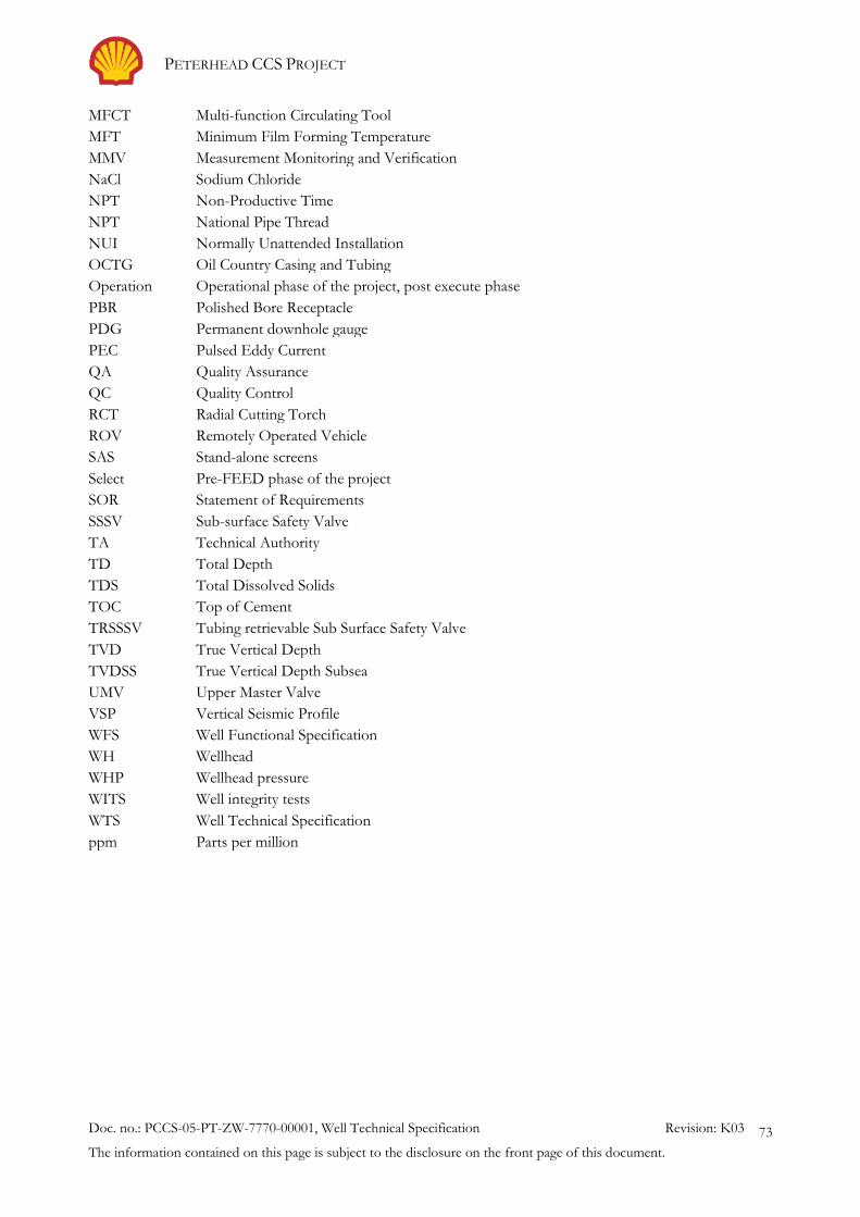
PETERHEAD CCS PROJECT
Doc. no.: PCCS-05-PT-ZW-7770-00001, Well Technical Specification Revision: K03
The information contained on this page is subject to the disclosure on the front page of this document.
73
MFCT Multi-function Circulating Tool
MFT Minimum Film Forming Temperature
MMV Measurement Monitoring and Verification
NaCl Sodium Chloride
NPT Non-Productive Time
NPT National Pipe Thread
NUI Normally Unattended Installation
OCTG Oil Country Casing and Tubing
Operation
PBR
Operational phase of the project, post execute phase
Polished Bore Receptacle
PDG Permanent downhole gauge
PEC Pulsed Eddy Current
QA Quality Assurance
QC Quality Control
RCT Radial Cutting Torch
ROV Remotely Operated Vehicle
SAS Stand-alone screens
Select
SOR
Pre-FEED phase of the project
Statement of Requirements
SSSV Sub-surface Safety Valve
TA Technical Authority
TD Total Depth
TDS Total Dissolved Solids
TOC Top of Cement
TRSSSV Tubing retrievable Sub Surface Safety Valve
TVD True Vertical Depth
TVDSS True Vertical Depth Subsea
UMV Upper Master Valve
VSP Vertical Seismic Profile
WFS Well Functional Specification
WH Wellhead
WHP Wellhead pressure
WITS Well integrity tests
WTS Well Technical Specification
ppm Parts per million
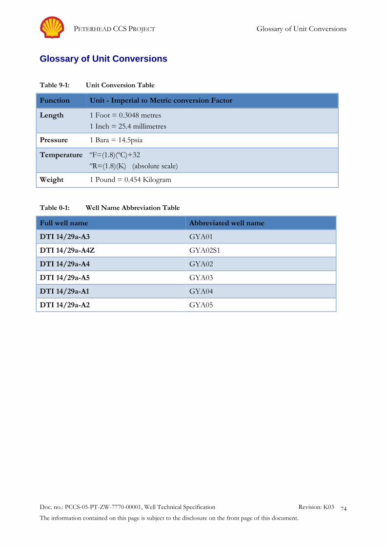
PETERHEAD CCS PROJECT Glossary of Unit Conversions
Doc. no.: PCCS-05-PT-ZW-7770-00001, Well Technical Specification Revision: K03
The information contained on this page is subject to the disclosure on the front page of this document.
74
Glossary of Unit Conversions
Table 9-1: Unit Conversion Table
Function Unit - Imperial to Metric conversion Factor
Length 1 Foot = 0.3048 metres
1 Inch = 25.4 millimetres
Pressure 1 Bara = 14.5psia
Temperature ºF=(1.8)(ºC)+32
ºR=(1.8)(K) (absolute scale)
Weight 1 Pound = 0.454 Kilogram
Table 0-1: Well Name Abbreviation Table
Full well name Abbreviated well name
DTI 14/29a-A3 GYA01
DTI 14/29a-A4Z GYA02S1
DTI 14/29a-A4 GYA02
DTI 14/29a-A5 GYA03
DTI 14/29a-A1 GYA04
DTI 14/29a-A2 GYA05

PETERHEAD CCS PROJECT Existing Well Schematic
Doc. no.: PCCS-05-PT-ZW-7770-00001, Well Technical Specification Revision: K03
The information contained on this page is subject to the disclosure on the front page of this document.
75
APPENDIX 1. Existing Well Schematic
Existing well schematic including the casing strings and conductor (GYA01).