Embed Size (px)
Citation preview

PETERHEAD CCS PROJECT FRONT MATTER
Doc. no.: PCCS-00-PTD-AA-5880-00001, Technology Maturation Plan. Revision: K04
The information contained on this page is subject to the disclosure on the front page of this document.
i
Peterhead CCS Project Doc Title: Technology Maturation Plan
Doc No.: PCCS-00-PTD-AA-5880-00001
Date of issue: 03/02/2016
Revision: K04
DECC Ref No.: 11.064
Knowledge Cat: KKD – Technical
KEYWORDS
Goldeneye, CO2, Technology Maturation, Risk.
Produced by Shell U.K. Limited
ECCN: EAR 99 Deminimus
© Shell U.K. Limited 2015.
Any recipient of this document is hereby licensed under Shell U.K. Limited’s copyright to use, modify, reproduce, publish, adapt and enhance this document.
IMPORTANT NOTICE
Information provided further to UK CCS Commercialisation Programme (the Competition)
The information set out herein (the Information) has been prepared by Shell U.K. Limited and its sub-contractors (the Consortium) solely for the Department for Energy and Climate Change in connection with the Competition. The Information does not amount to advice on CCS technology or any CCS engineering, commercial, financial, regulatory, legal or other solutions on which any reliance should be placed. Accordingly, no member of the Consortium makes (and the UK Government does not make) any representation, warranty or undertaking, express or implied as to the accuracy, adequacy or completeness of any of the Information and no reliance may be placed on the Information. In so far as permitted by law, no member of the Consortium or any company in the same group as any member of the Consortium or their respective officers, employees or agents accepts (and the UK Government does not accept) any responsibility or liability of any kind, whether for negligence or any other reason, for any damage or loss arising from any use of or any reliance placed on the Information or any subsequent communication of the Information. Each person to whom the Information is made available must make their own independent assessment of the Information after making such investigation and taking professional technical, engineering, commercial, regulatory, financial, legal or other advice, as they deem necessary.
PETERHEAD CCS PROJECT FRONT MATTER
Doc. no.: PCCS-00-PTD-AA-5880-00001, Technology Maturation Plan. Revision: K04
The information contained on this page is subject to the disclosure on the front page of this document.
ii
Table of Contents
Table of Figures iii
List of Tables iii
Executive Summary 1
1. Introduction 2
2. Technology Maturation Plan (TMP) 3
2.1. Technology Maturation Definition and Scope Summary 3
2.1.1. Technology Maturation Definition 3
2.1.2. Technology Maturation Scope 4
3. Technology and Procedures List 4
3.0. Introduction and Summary 4
3.1. Pipeline/Well Operating Envelope 7
3.2. CO2 Vapour / Liquid Equilibrium Data 8
3.3. Pipeline Running Ductile Fracture Prevention 9
3.4. Testing of Goldeneye Pipeline Internal Epoxy Coating 10
3.5. Assessment of Effect of Dense Phase CO2 on Non-Metallic (Elastomer) Materials 11
3.6. Assessment of Cement Stability in Downhole CO2 Environments 12
3.7. Extreme Cooling of Wellhead Material during Transient Conditions 13
3.8. CO2 compatible Subsurface Safety Valve (SSSV) Testing Procedure 15
3.9. Hydrate Inhibitor Selection 16
3.10. Multiple CO2 gas detector technology (Vapour/Dense phase) 17
3.11. Dense Phase CO2 Release Modelling Validation 19
3.12. Leakage Identification and Quantification 21
3.13. Tracer Selection and Addition/CO2 Fingerprinting 23
3.14. 4D Streamer in Combination with Ocean Bottom Nodes (OBN) 24
3.15. Pitting of 13% Cr Tubing Material 25
3.16. Design for Blowdown of Supercritical CO2 26
3.17. Geochemical Probe 27
3.18. Sediment and Pore-gas Sampling Method 28
3.19. CO2 Uncontrolled release Measures Analysis 29
3.20. Extended Downhole Pressure Measurements 30
3.21. Distributed Acoustic Sensing 32
3.22. Well Materials Fatigue Testing 33
3.23. Pipeline Mechanical Connectors 34
3.24. Intelligent Inspection Pigging Tools 36
PETERHEAD CCS PROJECT FRONT MATTER
Doc. no.: PCCS-00-PTD-AA-5880-00001, Technology Maturation Plan. Revision: K04
The information contained on this page is subject to the disclosure on the front page of this document.
iii
3.25. Large Size Booster Fan in Flue Gas Duty 37
3.26. Large Cansolv Pre-scrubber and Absorber 38
3.27. Rotary Type Gas / Gas Heat Exchanger for Flue Gas Service 40
3.28. Liner in Pre-Scrubber and Absorber Units with new amine solvent 41
3.29. Application of Cansolv Amine Solvent 43
3.30. Large Plate Type Heat Exchangers in Flue Gas Services 45
3.31. Catalytic Removal of Oxygen from CO2 46
3.32. Molecular Sieves for Dehydration in CO2 Service 47
3.33. Integral Geared Compressor with Integrated Cooler Knock-Out Vessels 48
3.34. Reclaiming Techniques for New Amine Solvent Service 49
3.35. Biological Treatment of Aqueous Effluent Containing Amines and Degradation Products 50
3.36. Fibre Optics based CO2 Sensor 52
3.37. Subsurface Safety Valve for CO2 Injection Wells 53
3.38. Pressure Control Equipment for Well Intervention 54
3.39. Rig Qualification for CO2 intervention 55
3.40. Tubing Material Selection 56
3.41. Impact of Contaminants in CO2 Stream 57
4. Conclusions 58
5. References – Bibliography 59
6. Glossary of Terms 60
Table of Figures
Figure 1-1: Project Location 2
List of Tables
Table 3-1: Immature Technologies 4
PETERHEAD CCS PROJECT Executive Summary
Doc. no.: PCCS-00-PTD-AA-5880-00001, Technology Maturation Plan. Revision: K04
The information contained on this page is subject to the disclosure on the front page of this document. 1
Executive Summary
This report outlines the technologies that either require development work as part of the FEED phase of the Peterhead Carbon Capture and Storage (CCS) demonstration project, or are currently at a research and development level.
This Technology Maturation Plan (TMP) is specific to the Peterhead CCS project. It captures the application of new technology and procedures that are currently in the Research and Development (R&D) phase, or commonly used mature hydrocarbon field applications which require modification for CCS purposes.
The TMP describes the outcome for the technologies which have been matured and made ready for application during the FEED phase of this project – as required by the project timeline. The process by which these technologies will be matured in the future phases of the project is described for those still awaiting development.
Of the forty one technologies listed in the maturation plan, thirty two have been closed to date and nine will be addressed in the Execute phase post Financial Investment Decision (FID). There do not appear to be any ‘show-stoppers’ amongst the technologies still to be matured, both in terms of development and schedule. However it must be appreciated that due to the ‘First of a Kind’ nature of the Peterhead CCS project, certain risks cannot be eliminated and will need to be mitigated as far as reasonably practicable.
The TMP will be updated periodically to address any newly identified additional technology requirements or to recognise the completion of the maturation process for each technology currently under consideration.
PETERHEAD CCS PROJECT
Doc. no.: PCCS-00-PTD-AA-5880-00001, Technology Maturation Plan. Revision: K04
The information contained on this page is subject to the disclosure on the front page of this document. 2
1. Introduction
The Peterhead Carbon Capture and Storage (CCS) Project aims to capture around one million tonnes of CO2 per annum, over a period of 15 years, from an existing Combined Cycle Gas Turbine (CCGT) located at SSE’s Peterhead Power Station in Aberdeenshire, Scotland. This would be the world’s first commercial scale demonstration of post combustion CO2 capture, transport and offshore geological storage from a gas-fired power station.
Post cessation of production, the Goldeneye gas-condensate production facility will be modified to allow the injection of dense phase CO2 captured from the post-combustion gases of Peterhead Power Station into the depleted Goldeneye reservoir.
The CO2 will be captured from the flue gas produced by one of the gas turbines at Peterhead Power Station (GT-13) using amine based technology provided by Cansolv (a wholly owned subsidiary of Shell). After capture the CO2 will be routed to a compression facility, where it will be compressed, cooled and conditioned for water and oxygen removal to meet suitable transportation and storage specifications. The resulting dense phase CO2 stream will be transported direct offshore to the wellhead platform via a new offshore pipeline which will tie-in subsea to the existing Goldeneye pipeline.
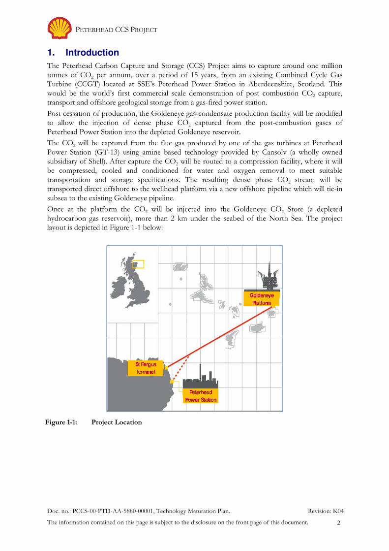
Once at the platform the CO2 will be injected into the Goldeneye CO2 Store (a depleted hydrocarbon gas reservoir), more than 2 km under the seabed of the North Sea. The project layout is depicted in Figure 1-1 below:
Figure 1-1: Project Location
PETERHEAD CCS PROJECT Technology Maturation Plan (TMP)
Doc. no.: PCCS-00-PTD-AA-5880-00001, Technology Maturation Plan. Revision: K04
The information contained on this page is subject to the disclosure on the front page of this document. 3
2. Technology Maturation Plan (TMP)
2.1. Technology Maturation Definition and Scope Summary
This report outlines the technologies that either require development work as part of the Define phase of the Peterhead CCS demonstration project, or are currently at a research and development level. At this point the Technology Maturation Plan (TMP) captures the immature technologies/process recognised as identified up to Q4 2015. It is based on the Concept Select Technology Maturation Plan with three new items introduced during FEED. Workshops were held at the end of 2014, and in mid-2015 to review the Technology Maturation plan and the results have been included in the current version. During these workshops the selection of the activities required to mature the items were discussed and prioritized (including definition of additional studies in parallel to FEED). The workshops also identified additional information required and where possible interdependencies exist. This was then reviewed by the Shell Technical Authorities. The items for development are described individually and are usually specific to a particular discipline – which is identified as the ‘Project Owner’.
In all cases, it is important to align the programme with Research & Development (R&D) projects (ongoing, planned or may qualify as input to a future research programme) whether internally within Shell, between partners in the project or joint with industry/university bodies.
In the absence of aligned research projects, there is a need to rank the immature technologies/procedures based upon the necessity to outsource the maturation process and ensure the result is obtained within a time frame that fits with the project timeline.
It is noted that one of the objectives of gas CCS demonstration projects is to define and resolve any technology gaps for the development, design and operation of integrated CCS facilities.
2.1.1. Technology Maturation Definition
This Technology Maturation Plan (TMP) is specific to the Peterhead CCS project. It captures the application of new technology and procedures that are currently in the Research and Development (R&D) phase, or commonly used mature hydrocarbon field applications which require modification for CCS purposes. These technologies were initially selected during the Concept Select phase as part of the base case plan, or were identified as a strong option where they are considered key in order to deliver or enhance the value of project. During the FEED phase many of the items have been developed further to the point that they are considered closed from a technology maturation standpoint, in some cases it has been decided not to pursue the item any further, and three new items have been added to the TMP list.
The TMP describes the outcome for the technologies which have been matured and made ready for application during the FEED phase of this project – as required by the project timeline. The process by which these technologies will be matured in the future phases of the project is described for those still awaiting development.
The plan for each technology includes:
• Technology description and its purpose;
• Technology benefit;
• Key activities or decisions to mature technology;
• Major conclusions;
• Current actions;
• References;
• Status.
PETERHEAD CCS PROJECT Technology and Procedures List
Doc. no.: PCCS-00-PTD-AA-5880-00001, Technology Maturation Plan. Revision: K04
The information contained on this page is subject to the disclosure on the front page of this document. 4
2.1.2. Technology Maturation Scope
The immature technologies/procedures under consideration will be applied within surface facilities (onshore plant, pipelines and platform), wells and subsurface.
3. Technology and Procedures List
3.0. Introduction and Summary
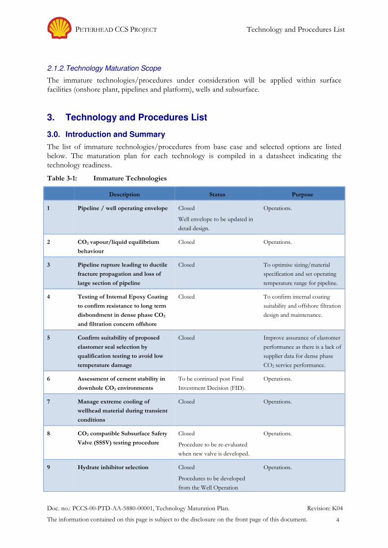
The list of immature technologies/procedures from base case and selected options are listed below. The maturation plan for each technology is compiled in a datasheet indicating the technology readiness.
Table 3-1: Immature Technologies
Description Status Purpose
1 Pipeline / well operating envelope Closed
Well envelope to be updated in
detail design.
Operations.
2 CO2 vapour/liquid equilibrium
behaviour
Closed Operations.
3 Pipeline rupture leading to ductile
fracture propagation and loss of
large section of pipeline
Closed To optimise sizing/material
specification and set operating
temperature range for pipeline.
4 Testing of Internal Epoxy Coating
to confirm resistance to long term
disbondment in dense phase CO2
and filtration concern offshore
Closed To confirm internal coating
suitability and offshore filtration
design and maintenance.
5 Confirm suitability of proposed
elastomer seal selection by
qualification testing to avoid low
temperature damage
Closed Improve assurance of elastomer
performance as there is a lack of
supplier data for dense phase
CO2 service performance.
6 Assessment of cement stability in
downhole CO2 environments
To be continued post Final
Investment Decision (FID).
Operations.
7 Manage extreme cooling of
wellhead material during transient
conditions
Closed Operations.
8 CO2 compatible Subsurface Safety
Valve (SSSV) testing procedure
Closed
Procedure to be re-evaluated
when new valve is developed.
Operations.
9 Hydrate inhibitor selection Closed
Procedures to be developed
from the Well Operation
Operations.
PETERHEAD CCS PROJECT Technology and Procedures List
Doc. no.: PCCS-00-PTD-AA-5880-00001, Technology Maturation Plan. Revision: K04
The information contained on this page is subject to the disclosure on the front page of this document. 5
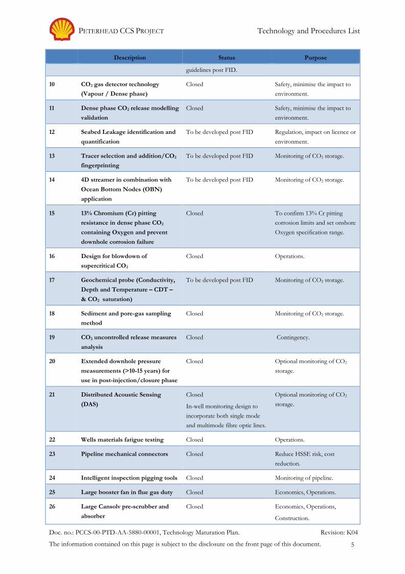
Description Status Purpose
guidelines post FID.
10 CO2 gas detector technology
(Vapour / Dense phase)
Closed Safety, minimise the impact to
environment.
11 Dense phase CO2 release modelling
validation
Closed Safety, minimise the impact to
environment.
12 Seabed Leakage identification and
quantification
To be developed post FID Regulation, impact on licence or
environment.
13 Tracer selection and addition/CO2
fingerprinting
To be developed post FID Monitoring of CO2 storage.
14 4D streamer in combination with
Ocean Bottom Nodes (OBN)
application
To be developed post FID Monitoring of CO2 storage.
15 13% Chromium (Cr) pitting
resistance in dense phase CO2
containing Oxygen and prevent
downhole corrosion failure
Closed To confirm 13% Cr pitting
corrosion limits and set onshore
Oxygen specification range.
16 Design for blowdown of
supercritical CO2
Closed Operations.
17 Geochemical probe (Conductivity,
Depth and Temperature – CDT –
& CO2 saturation)
To be developed post FID Monitoring of CO2 storage.
18 Sediment and pore-gas sampling
method
Closed Monitoring of CO2 storage.
19 CO2 uncontrolled release measures
analysis
Closed Contingency.
20 Extended downhole pressure
measurements (>10-15 years) for
use in post-injection/closure phase
Closed Optional monitoring of CO2
storage.
21 Distributed Acoustic Sensing
(DAS)
Closed
In-well monitoring design to
incorporate both single mode
and multimode fibre optic lines.
Optional monitoring of CO2
storage.
22 Wells materials fatigue testing Closed Operations.
23 Pipeline mechanical connectors Closed Reduce HSSE risk, cost
reduction.
24 Intelligent inspection pigging tools Closed Monitoring of pipeline.
25 Large booster fan in flue gas duty Closed Economics, Operations.
26 Large Cansolv pre-scrubber and
absorber
Closed Economics, Operations,
Construction.
PETERHEAD CCS PROJECT Technology and Procedures List
Doc. no.: PCCS-00-PTD-AA-5880-00001, Technology Maturation Plan. Revision: K04
The information contained on this page is subject to the disclosure on the front page of this document. 6
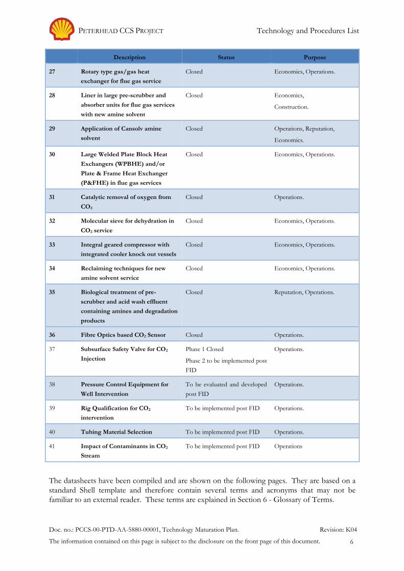
Description Status Purpose
27 Rotary type gas/gas heat
exchanger for flue gas service
Closed Economics, Operations.
28 Liner in large pre-scrubber and
absorber units for flue gas services
with new amine solvent
Closed Economics,
Construction.
29 Application of Cansolv amine
solvent
Closed Operations, Reputation,
Economics.
30 Large Welded Plate Block Heat
Exchangers (WPBHE) and/or
Plate & Frame Heat Exchanger
(P&FHE) in flue gas services
Closed Economics, Operations.
31 Catalytic removal of oxygen from
CO2
Closed Operations.
32 Molecular sieve for dehydration in
CO2 service
Closed Economics, Operations.
33 Integral geared compressor with
integrated cooler knock out vessels
Closed Economics, Operations.
34 Reclaiming techniques for new
amine solvent service
Closed Economics, Operations.
35 Biological treatment of pre-
scrubber and acid wash effluent
containing amines and degradation
products
Closed Reputation, Operations.
36 Fibre Optics based CO2 Sensor Closed Operations.
37 Subsurface Safety Valve for CO2
Injection
Phase 1 Closed
Phase 2 to be implemented post
FID
Operations.
38 Pressure Control Equipment for
Well Intervention
To be evaluated and developed
post FID
Operations.
39 Rig Qualification for CO2
intervention
To be implemented post FID Operations.
40 Tubing Material Selection To be implemented post FID Operations.
41 Impact of Contaminants in CO2
Stream
To be implemented post FID Operations
The datasheets have been compiled and are shown on the following pages. They are based on a standard Shell template and therefore contain several terms and acronyms that may not be familiar to an external reader. These terms are explained in Section 6 - Glossary of Terms.

PETERHEAD CCS PROJECT Technology and Procedures List
Doc. no.: PCCS-00-PTD-AA-5880-00001, Technology Maturation Plan. Revision: K04
The information contained on this page is subject to the disclosure on the front page of this document. 7
3.1. Pipeline/Well Operating Envelope
Category Process/Facilities Author / Project Owner Wells/Surface Facilities
Technology Name Pipeline/well operating envelope
Description & Purpose The current design relies on frictional loss through the well string to keep the fluid single dense phase during injection. There are a number of uncertainties that require validating to confirm the operating envelope:
a) Performance will be sensitive to assumed frictional loss down tubing; b) The operating range per well is relatively small. Flexibility in the injection range is
given by using wells with different injection envelopes c) Operating envelope per well should be recalculated based on the reservoir pressure
just before injection starts and considering the well availability.
Specific Benefits of Technology
(Quantify by DG3)
This study will ensure that CO2 injection well operating envelope is well within the tolerance and that it has a non-zero safety factor. It will ensure that the wells are capable of accommodating the capacity of Carbon Capture Plant (CCP) injection envelope.
Improved confidence in selected concept – reduction of risk (financial)
Key Activities or Decisions to mature Technology
Required by Key Resources
• Update reservoir pressure (and development upon injection)
• Ensure the tubing size and cross-over proposed for each well is valid for that reservoir pressure.
• Ensure that the wells are capable of injecting CCP operating envelope.
• Ensure pipeline operating envelope is integrated with wells operating envelope.
• Well operability under variable injection rate.
Updated in FEED
Requires further update during detail design in case of different reservoir pressure development, change on CCP rates or specific well availability issue.
None required
Major Conclusions Well Modelling with respect to the number of wells and their tubing sizes was updated during FEED.
• For current reservoir prediction, overlapping wells operating envelope is large enough to accommodate CCP injection rates.
• All wells will have 4 ½” and 3 ½” installed with a crossover tailored to the well.
• No future workover in wells is required for current reservoir pressure range prediction.
• Combination of injection wells can handle the arrival CO2 rate to the platform considering the estimated pressures and injectivities.
• Predicted to inject in a single well for the first years of injection and to have 2 wells on injection after year 10 of injection.
Changing the cross-over depth can modify the well operating envelope per well. Final decisions in detail design to
be made depending on well availability and estimated reservoir pressures.
Current Actions (next 3 months)
N/A
Additional Comments
N/A
Status: Closed
Well envelope to be updated in detail design
PETERHEAD CCS PROJECT Technology and Procedures List
Doc. no.: PCCS-00-PTD-AA-5880-00001, Technology Maturation Plan. Revision: K04
The information contained on this page is subject to the disclosure on the front page of this document. 8
3.2. CO2 Vapour / Liquid Equilibrium Data
Category Process/Facilities Author / Project Owner Surface Facilities
Technology Name CO2 vapour/liquid equilibrium data
Description & Purpose Some key design decisions are based on CO2 thermodynamics. Whilst the single component thermodynamic data has a high level of confidence, for example the NIST web-site using the Spanning and Danner Equation of State (EOS), the behaviour of CO2 in multi-component systems is less well validated. The issues that are of concern are:
a) Solubility of water in CO2 and water dewpoints over the complete range of operation b) The solubility of methanol (MeOH) in CO2 – necessary for the design of the well vent
system and behaviour of MeOH when injected in the tubing and in the reservoir c) The impact of H2/N2 on the bubble line of CO2 – this necessary for the determination
of running ductile fracture conditions. d) Partition between O2 in CO2 and formation water – necessary for understanding the
O2 spec and preventing pitting corrosion in 13% Cr stainless steel. e) Pressure, Volume, Temperature (PVT) behaviour of actual CO2 mixture (subsurface
requirement)
Specific Benefits of Technology
(Quantify by DG3)
Corrosion strategy (pipelines and well tubing).
Design of well vent system.
Running ductile fracture.
The impact on release profiles to be assessed.
Key Activities or Decisions to mature Technology
Required by Key Resources
Data Collection, followed up by confirmation in the range of operating envelope in detail design phase (this includes the impact of trace components identified in Test Centre Mongstad Cansolv testing, see Item 3.41)
Detailed design University research Herriot Watt/ Imperial Shell Research
Major Conclusions Ensure that safety aspects are included while investigating the contaminant impact on the CO2 mix phase diagram.
Regarding item d) O2 specification, further testing has allowed confirmation of suitability of materials in the wells.
Current Actions (next 3 months)
N/A
Additional Comments
N/A
Status: Closed

PETERHEAD CCS PROJECT Technology and Procedures List
Doc. no.: PCCS-00-PTD-AA-5880-00001, Technology Maturation Plan. Revision: K04
The information contained on this page is subject to the disclosure on the front page of this document. 9
3.3. Pipeline Running Ductile Fracture Prevention
Category Materials/Pipelines/Process/Facilities
Author / Project Owner Materials
Technology Name Pipeline Running Ductile Fracture Propagation
Description & Purpose Current design requires CO2 gas to be cooled onshore to 29°C maximum to prevent running ductile with the temperature limit depending on the composition of the CO2 (inerts). This requires installation of an after-cooler downstream of 6th stage compression at Peterhead and this is currently designed to limit maximum export temperature to 25°C thus providing contingency. Further work is required to confirm cooling requirements based on:
a) Sizing new export pipeline section from Peterhead to offshore tie-in point with existing Goldeneye pipeline;
b) Further validation of Batelle “two curve” method for dense phase CO2 based on final gas composition.
Specific Benefits of Technology
(Quantify by DG3)
Improved safety and reliability of the system/lower cost options
Key Activities or Decisions to mature Technology
Required by Key Resources
Confirmation of present option and evaluation of alternative
End of FEED Materials, Process, Pipelines
Major Conclusions Main work carried out in previous project phase. Running ductile fracture considered unlikely but optimisation based on inspection of existing pipeline and new pipeline sizing, plus confirmation of CO2 source composition will improve predictions and cooling requirements.
Current Actions (next 3 months)
No further work carried out to further optimise base case. The design confirms 29°C maximum inlet temperature remains base case.
Additional Comments
N/A
Status: Closed
PETERHEAD CCS PROJECT Technology and Procedures List
Doc. no.: PCCS-00-PTD-AA-5880-00001, Technology Maturation Plan. Revision: K04
The information contained on this page is subject to the disclosure on the front page of this document. 10
3.4. Testing of Goldeneye Pipeline Internal Epoxy Coating
Category Materials/Pipelines/Process/Facilities
Author / Project Owner Materials
Technology Name Testing of Internal Epoxy Coating
Description & Purpose Goldeneye pipeline is internally coated with a thin film epoxy coating. The integrity of the coating when exposed to dense phase CO2 long term and under all decompression conditions has not been fully established. There is a risk of disbonding with coating particles causing well plugging if no filters are installed upstream of wells. Some testing has been carried out to confirm coating behaviour in CO2 in Longannet FEED phase but this may need supplementary longer term testing.
Specific Benefits of Technology
(Quantify by DG3)
Improved confidence of likelihood of disbonding occuring which can be used to confirm filtration strategy.
Key Activities or Decisions to mature Technology
Required by Key Resources
Carry out laboratory testing Complete in FEED Materials
Major Conclusions Testing during Longannet FEED and during Peterhead CCS Concept Select has confirmed coating resistant to decompression in dense phase CO2. This has provided confidence in coating integrity.
Long term test data was acquired from Shell labs in Rijswijk which demonstrated no degradation over a period in excess of 1year.
Current Actions (next 3 months)
N/A
Additional Comments
N/A
Status: Closed
PETERHEAD CCS PROJECT Technology and Procedures List
Doc. no.: PCCS-00-PTD-AA-5880-00001, Technology Maturation Plan. Revision: K04
The information contained on this page is subject to the disclosure on the front page of this document. 11
3.5. Assessment of Effect of Dense Phase CO2 on Non-Metallic (Elastomer) Materials
Category Materials Author / Project Owner Materials
Technology Name Effect of dense phase CO2 on non-metallic elastomer materials for seals.
Description & Purpose Elastomer seals in existing valves are unsuitable for CO2 and are all to be replaced in valves identified for refurbishment. In addition for replacement new valves CO2 resistant seals will be specified. Previous assessment has identified there is insufficient standard test data to give performance assurance in all operating scenarios. Updated vendor compatibility testing review is required along with agreed testing scope on need for further testing particularly decompression and low temperature resistance/compatibility in dense phase.
Specific Benefits of Technology
(Quantify by DG3)
Improved confidence with respect to elastomer performance and compatibility in CCS CO2 environments and with reliability of seal functioning in valves, etc.
Key Activities or Decisions to mature Technology
Required by Key Resources
Perform laboratory qualification testing of selected elastomers in typical CCS CO2 environments (using vendors or Shell labs)
Complete in FEED Materials
Major Conclusions Longannet extended FEED documented testing framework definition. Communication with vendors started.
Current Actions (next 3 months)
Testing no longer required. All valves to be removed and refurbished or replaced topside Goldeneye. Resistant non-metallic seals will be specified with Supplier compatibility testing to verify selection.
Additional Comments
NA
Status: Closed
PETERHEAD CCS PROJECT Technology and Procedures List
Doc. no.: PCCS-00-PTD-AA-5880-00001, Technology Maturation Plan. Revision: K04
The information contained on this page is subject to the disclosure on the front page of this document. 12
3.6. Assessment of Cement Stability in Downhole CO2 Environments
Category Materials Author / Project Owner Materials
Technology Name Assessment of cement stability in downhole CO2 environments.
Description & Purpose Cement used to fix and protect casing in the formation is, in principle, subject to degradation by CO2. The cement used at present in the Goldeneye wells has been judged sufficiently resistant to CO2, based on analogue application and test work. Alternative and improved cements are offered on the market but no data is available to judge the performance of these products as yet. In particular, long term behaviour is often unknown. Investigation of proven and alternative cements may reveal new suitable cements for Goldeneye. The main purpose of this technology is for well abandonment (after CO2 injection) and potential sidetracks (currently not in the reference case)
Specific Benefits of Technology
(Quantify by DG3)
While the presently used cement in Goldeneye is judged suitable, the availability of alternatives may offer improved performance, longer life or lower cost, all in the context of long term injection well integrity.
Key Activities or Decisions to mature Technology
Required by Key Resources
Investigate stability of candidate cements in literature and by contacting suppliers.
Detailed design Well Engineer (WE) resource and Houston lab testing
Major Conclusions There are a few alternatives to the presently used cement in Goldeneye. Current cement used in Goldeneye shows good resistance properties. An investigation potentially broadens the range of suitable candidate cement types. Information to be requested from suppliers.
Current Actions (next 3 months)
N/A
Additional Comments
Evaluation of available cement types to continue.
Continue monitoring the market for changes to cement types and other CCS based applications of cement and alternatives.
Status: To be continued post Final Investment Decision (FID)

PETERHEAD CCS PROJECT Technology and Procedures List
Doc. no.: PCCS-00-PTD-AA-5880-00001, Technology Maturation Plan. Revision: K04
The information contained on this page is subject to the disclosure on the front page of this document. 13
3.7. Extreme Cooling of Wellhead Material during Transient Conditions
Category CO2 Injection Wells (Production Technology)
Author / Project Owner Wells
Technology Name Manage extreme cooling of wellhead during operational transient conditions and evaluate the suitability of the wellhead under atmospheric leak conditions.
Description & Purpose Due to Joule Thomson cooling effect, low temperatures are encountered at the top of the well for normal transient conditions depending on reservoir pressure and very low temperatures are encountered in case of releases depending on the hole size.
There may be a scenario where the temperature of CO2 at the wellhead is below the wellhead temperature rating taking the tubing and casing hangers below their rating, causing catastrophic failure of the well.
Specific Benefits of Technology
(Quantify by DG3)
This study will ensure well integrity for different well components, especially for the wellhead. It will ensure that wellhead rating is sufficient (with safety factor taken into account) for potential leak scenarios.
Key Activities or Decisions to mature Technology
Required by Key Resources
• Detailed analysis of wellhead temperature rating.
• Detailed modelling of cooling when CO2 is released.
• Ensure there is a safety margin in terms of wellhead temperature rating and well design case.
• Check if the CO2 temperature is seen at the casing hanger of wellhead.
• Possible experimental work, potentially in partnership with Statoil.
• Conclude if the current wellhead can be used.
FID, Detailed Design, and ultimately before wells execution.
Completion Engineer and Vendor (Cameron), PTI reactor modelling.
Major Conclusions The current wellhead can be used for CO2 injection.
Computational Fluid Dynamic Modelling (CFD) performed for CO2 releases scenarios. The model shows that for small weeps and seeps and releases modelled of up to 28 mm there is no significant cooling at the wellhead. For larger releases i.e. 50 mm in diameter modelling revealed that components of the wellhead system can see an excursion below the design rating. However, there is no credible scenario leading to a release of CO2.
CFD modelling for two phase injection (no friction injection, in a stuck choke situation, for low reservoir pressures) for less than 10 hours will not affect the wellhead. Wellhead steel temperature would be above the current limit.
In addition, the same material used in the existing wellhead can be qualified to lower temperatures. Mock-up tests are not required for the wellhead.
Special considerations to other well elements in the top of the well are required based on the modelling results:
• New tree to be installed in the injector wells, API temperature class ‘K’.
• Minimise the probability of surface leaks by installing metal to metal seals at the tree.
• Tubing above the Subsurface Safety Valve (SSSV) with more resistance to lower temperatures (S13Cr).
• SSSV is under development for the expected conditions during a CO2 release. This is now part of TMP; Sheet 3.39.
Engineering Criticality assessment on the Wellhead with the modelling results and CFD analysis demonstrates the existing wellhead is fit for purpose.
Current Actions (next 3 months)
Prepare a document specific to wellhead cooling.

PETERHEAD CCS PROJECT Technology and Procedures List
Doc. no.: PCCS-00-PTD-AA-5880-00001, Technology Maturation Plan. Revision: K04
The information contained on this page is subject to the disclosure on the front page of this document. 14
Additional Comments
Subsurface safety valve under development for the expected conditions during a highly unlikely release scenario.
Status: Closed
PETERHEAD CCS PROJECT Technology and Procedures List
Doc. no.: PCCS-00-PTD-AA-5880-00001, Technology Maturation Plan. Revision: K04
The information contained on this page is subject to the disclosure on the front page of this document. 15
3.8. CO2 compatible Subsurface Safety Valve (SSSV) Testing Procedure
Category CO2 Injection Wells (Production Technology)
Author / Project Owner Wells
Technology Name CO2 compatible Subsurface Safety Valve (SSSV) testing procedure.
Description & Purpose SSSV Testing procedure for CO2 injection wells. Bleeding-off of CO2 at the top of the well to a pressure of ~10% of the closed-in tubing head pressure.
Status pre DG-3: Tentative outcomes show SSSV testing procedure will be a long process, unlike hydrocarbon wells. Required to ensure SSSV setting depth and to demonstrate that the operation can be carried out without having an impact on well integrity.
Specific Benefits of Technology
(Quantify by DG3)
This study will ensure CO2 injection well integrity specifying that SSSV will work during emergency (e.g. blow-out) situation. An alternative, less time consuming method should be studied.
Key Activities or Decisions to mature Technology
Required by Key Resources
• Ensure that wellhead pressure can be reduced to ~10% of closed in wellhead pressure.
• Investigate time required for the operation is practical.
• Ensure that the low temperature excursion during the test is within SSSV metallurgy design temperature limit.
FEED – Guideline developed.
SSSV testing procedure to be developed during detail design phase.
Production Technologist and Completions Engineer
Major Conclusions OLGA study carried out for different well conditions (geothermal post injection and different reservoir pressures) to determine how to bleed-off the pressure and how to re-commence injection after the test of the SSSV. The main conclusions are:
• Slow process (~12 h) depending on well condition.
• Reduce bleed-off pressure to ~24 bar considering the current limitation of the SSSV of -7°C and to reduce the JT cooling after the start of injection. It is not advisable to bleed-off to the standard 10% of the High Closed In Tubing Head Pressure (CITHP).
• Preferred to do the bleed-off pressure in a controlled/automatic manner.
• Low temperatures at the gas/liquid CO2 interface cannot be detected at wellhead (operational challenge).
• Operational mistake (by bleeding off quickly to atmospheric conditions) can create metal temperature as low as –56°C.
• Use the Distributed Temperature system to help reduce the bleed-off time.
Current Actions (next 3 months)
N/A
Additional Comments
SSSV testing guideline developed with the current SSSV limitations. To be re-evaluated once the valve is re-qualified or developed.
Status: Closed
Procedure to be re-evaluated when new valve is developed.
PETERHEAD CCS PROJECT Technology and Procedures List
Doc. no.: PCCS-00-PTD-AA-5880-00001, Technology Maturation Plan. Revision: K04
The information contained on this page is subject to the disclosure on the front page of this document. 16
3.9. Hydrate Inhibitor Selection
Category CO2 Injection Wells (Production Technology)
Author / Project Owner Wells
Technology Name Hydrate inhibitor selection.
Description & Purpose Gas/CO2 hydrates are a potential problem, occurring at low temperature and high pressure in the presence of free water. In order to avoid the formation of gas hydrates, a gas hydrate inhibitor is required to be injected. This study will determine if an inhibitor is required and, if it is, what formulation will be most effective.
Specific Benefits of Technology
(Quantify by DG3)
The outcome of this study will be to ensure that the risk hydrate formation is properly managed. If this was not studied and gas hydrate did form during operation, it can have serious impact on well injectivity and well integrity.
Key Activities or Decisions to mature Technology
Required by Key Resources
• Detailed analysis on the implications of using Mono-Ethylene Glycol (MEG)/water or Methanol as a hydrate inhibitor compared to Methanol (MeOH). In particular:
1. Review the hydrate inhibition afforded by MEG/water vs. MeOH & any applicability issues under operating conditions (e.g. gelling).
2. Estimate how long the gas hydrate inhibitor must be injected into the well on start-up/re-start of CO2 injection in the well.
3. Check if MeOH or MEG/water will have a detrimental impact on the various materials contained within injection line and well components.
4. Check if the quantities / concentrations of the chosen hydrate inhibitor required for inhibition on start-up / re-start will have a detrimental impact on the reservoir matrix (e.g. clay swelling, fines mobilisation).
• Activities 1) & 2) should be delivered through a hydrate modelling study.
• Activity 3) should be delivered through a materials review with Wells and Materials disciplines.
• Activity 4) should be delivered through use of analogue data or via a core flood experiment, if necessary.
FEED confirmed the use of Methanol. Proposed to have batch injection between the SSSV and the tree.
Pumping procedures to be developed during the detail design phase.
Major Conclusions Methanol is the preferred hydrate inhibitor.
Batch inhibition to be carried out.
Hydrate inhibition guidelines developed.
Use of the hydrates limited during the well start up until free water is displaced from the well.
Current Actions (next 3 months)
N/A
Additional Comments
N/A
Status: Closed
Procedures to be developed from the Well Operation guidelines post FID.
PETERHEAD CCS PROJECT Technology and Procedures List
Doc. no.: PCCS-00-PTD-AA-5880-00001, Technology Maturation Plan. Revision: K04
The information contained on this page is subject to the disclosure on the front page of this document. 17
3.10. Multiple CO2 gas detector technology (Vapour/Dense phase)
Category Process Automation and Control
Author / Project Owner
Controls
Technology Name Multiple CO2 gas detector technology (Vapour/Dense phase).
Description & Purpose
As part of the carbon capture storage project a review of CO2 detector technology shall be required, due to the negative effect detector operations may have during a CO2 release (i.e. dense phase CO2 release temperatures can drop to -70°C). As this could have a significant impact for safeguarding personnel and equipment, a report will be required detailing tests carried out and the proposed solution for the project. This review is typically carried out by Fire & Gas specialists (i.e. Shell Global Solutions) and shall ultimately FEED into this plan.
Types of CO2 detection that could be used in the project are:
• Acoustic detection;
• Thermal imaging camera;
• Mist detection;
• Existing CO2 detection (Laser Type); and
• Fibre optic temperature detection. A mixture of the above technologies could be used to develop an appropriate “voting” philosophy, which may increase reliability of the detector coverage. Confirmation of detection technologies and voting philosophies to be used shall be finalised during the Define phase of the project upon completion of technology testing and review.
Specific Benefits of Technology
(Quantify by DG3)
Early detection of CO2 gas in confined spaces and open areas for personnel safety.
CO2 early leak detection as part of European Union Emissions Trading Scheme (EU ETS) Directive.
Key Activities or Decisions to mature Technology
Required by Key Resources
Review results from existing CO2 release tests carried out at Spadeadam.
Review of detector work carried out on the Quest Project.
Investigate detector technologies to be used for CO2.
Identify any future qualification testing required.
Assistance with development of CO2 Detector Philosophy.
Future qualification testing of detector technology required at Spadeadam.
Q1 2014
Q1 2014
Q1/2 2014
Q1/2 2014
Q2 2014
Q2 2014
Process Automation Control Optimisation (PACO) - Shell Global Solutions International.
PACO - Shell Global Solutions International.
PACO - Shell Global Solutions International.
PACO - Shell Global Solutions International.
PACO - Shell Global Solutions International.
Spadeadam.
Vendor collaboration.
Major Conclusions Work completed. Existing CO2 detection technology can be applied and the methodology for its use has been developed based on testing performed during FEED.

PETERHEAD CCS PROJECT Technology and Procedures List
Doc. no.: PCCS-00-PTD-AA-5880-00001, Technology Maturation Plan. Revision: K04
The information contained on this page is subject to the disclosure on the front page of this document. 18
Current Actions (next 3 months)
No further work required.
Additional Comments No further work required.
Status: Closed.
PETERHEAD CCS PROJECT Technology and Procedures List
Doc. no.: PCCS-00-PTD-AA-5880-00001, Technology Maturation Plan. Revision: K04
The information contained on this page is subject to the disclosure on the front page of this document. 19
3.11. Dense Phase CO2 Release Modelling Validation
Category Health, Safety, Security and Environment (HSSE)
Author / Project Owner HSSE
Technology Name Dense phase CO2 release modelling validation
Description & Purpose Consequence models (e.g. Shell FRED) are widely used to model the release and dispersion of hydrocarbon within the oil & gas industry. Prior to the Peterhead CCS project commencing there was little or no experimental data available to validate these to model releases of dense phase CO2. The Spadeadam test programme was initiated to provide data to validate the release models and determine if they are suitable for use.
Specific Benefits of Technology
(Quantify by DG3)
Improved release modelling, better understanding of CO2 releases & dispersion to aid cost effective design & emergency response.
Key Activities or Decisions to mature Technology Required by Key Resources
The Spadeadam test programme can be described in two parts.
• Test Programme 1, tested unconfined jet releases (up to 1” (25 mm) diameter) of pure, dense phase CO2 consisting of 14 free releases (11 ambient temperature and 3 super-critical) into the field array of instruments. For the range of tests conducted the data has been used to validate Shell and 3rd party models. The test programme showed that although there is a reasonable proportion of solid CO2 formed immediately downstream of the release orifice it is in the form of very fine particles and thus follows the vapour flow. It also sublimes rapidly to CO2 vapour. This means that heavy gas dispersion models adequately predict hazard distances since significant solids deposition does not occur.
• Test Programme 2 (TP2). The objectives of TP2 were to study CO2 build-up in confined space; study temperature effect of structural steel; measure dry-ice formation; determine loss of visibility due to condensation cloud; study effectiveness of water deluge in subduing CO2 cloud; and study the performance of existing CO2 detectors. This test programme showed that in confined spaces that severe cold and high concentrations were generated although solid CO2 build-up was very limited. Visibility within the CO2 cloud (due to cold temperatures and resultant condensation of moisture atmospheric) showed that visibility was a concern for escape from the plume. Prediction of visible plume is possible with CFD modelling. Effectiveness of deluge was not proven in reducing CO2 concentrations. Some data has been gathered on temperature effects to structural steel but this but its use is limited.
Subsequent to the above experimental programmes there have since been pipeline tests conducted from which the data has been used to validate pipeline models (PIPETEC). This has shown that the 2-phase blowdown model used in FRED is adequately accurate. The next FRED software release will allow CO2 to be selected as fluid in the 2-phase model.
Most recently large scale release tests have been conducted at Spadeadam (previous tests were limited to 1" (25 mm) release orifice size). (The original intent to do these tests in the US utilising a pipeline CO2 source owned by Kinder Morgan unfortunately couldn’t be agreed). The Spadeadam test report came out in spring 2014, and DNV consultants conducted a data review principally to check flowrates for 2-phase releases with their report issued in late 2014. No major issues were identified.
Mid FEED – Q2 2014 Spadeadam. DNV
Major Conclusions In summary the current state of the available modelling tools for CO2 release is considered to be very reasonable for the Peterhead CCS Project. Sufficient confidence can be placed in the results of these models provided they are used appropriately.

PETERHEAD CCS PROJECT Technology and Procedures List
Doc. no.: PCCS-00-PTD-AA-5880-00001, Technology Maturation Plan. Revision: K04
The information contained on this page is subject to the disclosure on the front page of this document. 20
Current Actions (next 3 months)
N/A
Additional Comments
Retain an oversight of CCS industry developments and programmes.
References Spadeadam reports available on (1):
https://www.dnvgl.com/oilgas/innovation-development/joint-industry-projects/co2pipetrans.html
Status: Closed

PETERHEAD CCS PROJECT Technology and Procedures List
Doc. no.: PCCS-00-PTD-AA-5880-00001, Technology Maturation Plan. Revision: K04
The information contained on this page is subject to the disclosure on the front page of this document. 21
3.12. Leakage Identification and Quantification
Category Subsurface Author / Project Owner Subsurface
Technology Name Leakage identification and quantification – (method & technologies to measure volume & concentration at seabed & shallow depth)
Description & Purpose Leakage quantification is required by EU & UK legislation to determine the extent of corrective measure and penalty in the unlikely case that CO2 leaks from storage complex. The quantification of lateral leakage may be followed up by penalty payment and a requirement to license invaded pore volumes, whilst there is a greater need to contain vertical leakage because it has direct exposure to environment (in seabed and water column).
Specific Benefits of Technology
(Quantify by DG3)
• Identify and quantify volume of the leakage;
• Identify and quantify flow rate of the leakage; and
• Identify and quantify concentration of CO2 in the leakage.
Key Activities or Decisions to mature Technology
Required by Key Resources
• Engage with CO2 research, industry and universities to identify the appropriate techniques for volume, flow and concentration measurements at seabed and in very shallow and deep formations. In the absence of physical methods, establish theoretical methods to be certified by UK regulator (DECC).
Project start of injection. Shell staff supporting the ETI MMV project and STEMM-CCS projects; both research collaborations that aim to address this technology needs and develop deployable technology.
Major Conclusions Potential techniques have been identified (see table below). Further studies are required to determine detection limit and areal quantification as well as acquiring sufficient background for comparison. It should be identified if the detection limit covers the variation in the small range of concentration/flow & the areal extent of any likely leakage. In the absence of a suitable physical measurement method, due to limitation in detection, theoretical quantification will be required.
Engagement with research is required to establish which alternatives are likely to have matured by or during execution phase. These can be used as replacements in case of failure or lack of sensitivity from the main technologies. Also, Goldeneye can be used as field test for these alternative methods to benefit from research funding.
Current Actions (next 3 months)
N/A

PETERHEAD CCS PROJECT Technology and Procedures List
Doc. no.: PCCS-00-PTD-AA-5880-00001, Technology Maturation Plan. Revision: K04
The information contained on this page is subject to the disclosure on the front page of this document. 22
Additional Comments N/A
Status: To be developed post FID.
PETERHEAD CCS PROJECT Technology and Procedures List
Doc. no.: PCCS-00-PTD-AA-5880-00001, Technology Maturation Plan. Revision: K04
The information contained on this page is subject to the disclosure on the front page of this document. 23
3.13. Tracer Selection and Addition/CO2 Fingerprinting
Category Subsurface Author / Project Owner Subsurface.
Technology Name Tracer selection and addition/CO2 fingerprinting.
Description & Purpose To uniquely identify CO2 and other fluids stored in the Goldeneye storage site, either through the measurement of an intrinsic property of the CO2 being stored, or through the addition of an additional, identifiable, inert substance. This will enable definitive statements to be made about the origin of any CO2 collected by monitoring and sampling methods – whether it is from the Goldeneye storage site or from another storage site or is naturally occurring.
Specific Benefits of Technology
(Quantify by DG3)
Allow the unambiguous detection of stored CO2 if it migrates to shallower layers or is released at the seabed.
Key Activities or Decisions to mature Technology
Required by Key Resources
• Collect information on hydrocarbon (HC) fingerprinting in Goldeneye from asset team – because remaining light HC should be pushed in front of CO2 in leakage event.
• Collect natural CO2 baseline data (seabed) and analyse.
• Identify long term issues with PerFluoroCarbon (PFC) tracers, i.e. migration loss, long term stability, partitioning on CO2 phase change, compatibility with in situ HC and overburden rocks.
• Feasibility study on tracer injection location, concentration and appropriate method (currently continuous injection).
Literature/lab work by FID
Research at CSIRO, IFE and Shell Amsterdam for QUEST being supported by Shell.
Major Conclusions In the event of identification of CO2 at the seabed it is important to be able to determine if the flux is natural or from the CO2 store. Relying on the specific source CO2 signature to conclusively identify any leaked CO2 would be too ambiguous in the presence of naturally occurring CO2. The experiments have shown that PerFluoroCarbons (PFC) tracers partition into the methane that is left in the store after gas production. They also do not transfer effectively into the gas phase as the CO2 transitions from dense phase at depth. They also showed that natural isotopes of Xenon (Xe) do not suffer from these effects and that some of Xe isotopes are available at costs that can be used in a commercial scale project. Xe does have the challenge that it does occur naturally. This issue is overcome by introducing a number of different isotopes in a set ratio. As a result, a suite of Xe isotopes has been selected for use as a CO2 tracer.
Current Actions (next 3 months)
Collection of seabed baseline data might still take place as part of the STEMM-CCS project which PCCS supported during FEED.
Additional Comments N/A
Status: To be developed post FID
PETERHEAD CCS PROJECT Technology and Procedures List
Doc. no.: PCCS-00-PTD-AA-5880-00001, Technology Maturation Plan. Revision: K04
The information contained on this page is subject to the disclosure on the front page of this document. 24
3.14. 4D Streamer in Combination with Ocean Bottom Nodes (OBN)
Category Monitoring Author / Project Owner Subsurface
Technology Name 4D streamer in combination with ocean bottom nodes (OBN) application
Description & Purpose Time-lapse seismic uses the differences in acoustic images between a baseline and a monitor survey to detect changes in the reservoir and overburden. The combined use of OBN and towed streamer 4D seismic is a critical component of the Measurement, Monitoring and Verification (MMV) plan to monitor CO2 migration along the Plugged and Abandoned (P&A) wells, injectors wells, faults/fractures, in the Captain aquifer and/or in the water bearing formations in the overburden. The plan is to acquire 4D seismic with streamer vessels over the larger licence area, except for the platform area which is not accessible for streamer vessel. The platform area will be monitored using OBN. OBN is already a proven technology for deepwater applications, and there is growing experience in shallow water environments. Furthermore, the application of OBN technology is expected to rapidly further mature in the near future in terms of acquisition technology, acquisition cost and processing and integration with streamer seismic data.
Specific Benefits of Technology
(Quantify by DG3)
The combined use of OBN and streamer 4D seismic is a critical component of the MMV plan to monitor CO2 migration along the Plugged & Abandoned wells, injectors wells, faults/fractures, laterally in the Captain aquifer and/or in the water bearing formations in the overburden.
Key Activities or Decisions to mature Technology
Required by Key Resources
• Define fit-for-purpose OBN sampling requirements for shallow monitoring targets.
• Select most cost effective deployment option for nodes based on info from vendors and survey design study.
• Determine possible integration issues between streamer and OBN data. Allow for sufficient overlap if one to one merge of datasets is expected to be problematic.
• Include latest 4D acquisition developments – including low cost near platform solutions.
Survey tender after FID.
Seismic design team.
Major Conclusions The combined use of OBN and towed streamer seismic is a critical component of the MMV plan to provide a high quality 4D dataset for monitoring both the surrounding area and under the platform. For the detailed seismic survey design the state-of-the-art technology at that time should be used to determine fit-for-purpose sampling requirements for shallow subsurface targets, and cost effective deployment of nodes in shallow water, integration of streamer and OBN data, and low cost options for long term CCS monitoring.
Technology is currently matured and ready for deployment. Details pertinent to the project need to be defined in detail during tender exercise.
Current Actions (next 3 months)
N/A
Additional Comments N/A
Status: To be developed post FID

PETERHEAD CCS PROJECT Technology and Procedures List
Doc. no.: PCCS-00-PTD-AA-5880-00001, Technology Maturation Plan. Revision: K04
The information contained on this page is subject to the disclosure on the front page of this document. 25
3.15. Pitting of 13% Cr Tubing Material
Category Materials Author / Project Owner Materials
Technology Name Pitting of 13% Cr tubing material
Description & Purpose The well tubing and screens are made of 13% Cr which is subject to pitting corrosion attack in CCS CO2 service where O2 is present in the expected water-wet conditions in wellbore during early years of gas injection into wells. Initially the design basis was that O2 will be removed from the CO2 onshore to 1 ppm based on estimated equilibrium concentration of 10 ppb O2 in water. Testing is required to provide data quantifying susceptibility to corrosion in order to determine the extent of allowable higher O2 limit for operating excursions i.e. possible relaxation to current specification.
See related Technology Maturation Item 3.32 Catalytic Removal of Oxygen from CO2.
Specific Benefits of Technology
(Quantify by DG3)
Improved reliability and availability of the injection wells. Improved safety and system integrity as well failure would result in exposure of the casing to CO2;
Relaxed O2 limit in CO2 (also reducing need for H2 to remove O2).
Key Activities or Decisions to mature Technology
Required by Key Resources
Investigate O2 limit in wet CO2 with simulated formation water composition/chlorides to avoid pitting of 13% Cr by lab testing.
To be completed in FEED. Materials/Shell labs.
Major Conclusions Analysis of test results allows the O2 limit to be relaxed to 5 ppm.
Current Actions (next 3 months)
N/A
Additional Comments N/A
Status: Closed.
PETERHEAD CCS PROJECT Technology and Procedures List
Doc. no.: PCCS-00-PTD-AA-5880-00001, Technology Maturation Plan. Revision: K04
The information contained on this page is subject to the disclosure on the front page of this document. 26
3.16. Design for Blowdown of Supercritical CO2
Category Process/Facilities Author / Project Owner Surface Facilities
Technology Name Design for blowdown of supercritical CO2.
Description & Purpose The current design has a vent dedicated to depressuring the pipeline. If required, this system must operate reliably over a long period of time. The vent tip will contain a ~33 mm internal diameter (ID) orifice. The orifice will have to handle high pressure drops and may be subject to erosion. The pipework upstream relies on maintaining a pressure above the CO2 triple point to avoid gas break-out. This erosional risk to the vent will be confirmed by experimental trials at Spadeadam.
Modelling of temperatures in pipework and equipment during depressuring.
Specific Benefits of Technology
(Quantify by DG3)
CO2 vent design, materials selection to avoid low-temperature embrittlement.
Key Activities or Decisions to mature Technology
Required by Key Resources
The major milestone is the completion of the Spadeadam testing programme.
Discuss tip design with Vendors.
Investigate alternative strategies.
Consider initiating University Research Project to look at low temperature issues in depressuring of dense phase CO2.
Complete
Detailed design
Spadeadam
Vendors and Spadeadam
University Chemical Engineering Department
Major Conclusions
During the CO2 release programme, solids build up has not been witnessed as a significant problem around the release point or around the systems vents. The test programme has effectively blown down the release vessel from 150 bar to below saturation pressure without encountering system blockage by solids.
Temperature effects were an issue, where on blow down the temperature inside the CO2 vessel would drop rapidly. Also rapid cooling was observed in small vent lines.
Erosion due to CO2 solids was confirmed not to be an issue. During the test programme no erosion was encountered on any exposed equipment.
Current Actions (next 3 months)
N/A
Additional Comments
N/A
Status: Closed.

PETERHEAD CCS PROJECT Technology and Procedures List
Doc. no.: PCCS-00-PTD-AA-5880-00001, Technology Maturation Plan. Revision: K04
The information contained on this page is subject to the disclosure on the front page of this document. 27
3.17. Geochemical Probe
Category HSSE Author / Project Owner HSSE
Technology Name Geochemical probe (conductivity, depth and temperature – CDT – & CO2)
Description & Purpose Geochemical probes may allow for the detection of CO2 leakage at the seabed via a permanent leak detection system, powered from and providing real time data to the Goldeneye platform. For leak detection from the injection wells a mobile (Remotely Operated Vehicle – ROV – or Autonomous Underwater Vehicle – AUV) or semi-permanent (buoy or battery powered) system can be deployed in an area of suspected leakage (e.g., Plugged and Abandoned – P&A – wells).
Specific Benefits of Technology
(Quantify by DG3)
• Early detection of CO2 leakage from injection well annulus.
• Real time data allows for continuous detections.
• Detection and possible quantification of suspected seabed leaks (e.g., P&A wells).
• Provide a natural gas flux baseline.
Key Activities or Decisions to mature Technology
Required by Key Resources
• Identify potential geochemical probe vendors.
• Quantify detection limits of existing commercially available probes.
• Undertake subsea dispersion modelling.
• Identify subsea probe location based on subsea dispersion modelling.
• Liaise with marine institutes (NOC, GEOMAR) to establish if sampling tools are being developed.
Post FID To be determined in the next phase.
Major Conclusions Kongsberg Marine have produced a technical study for subsea geochemical monitoring at Goldeneye platform (North Sea) which identifies potential probes.
Current Actions (next 3 months)
N/A
Additional Comments N/A
Status: To be developed post FID.

PETERHEAD CCS PROJECT Technology and Procedures List
Doc. no.: PCCS-00-PTD-AA-5880-00001, Technology Maturation Plan. Revision: K04
The information contained on this page is subject to the disclosure on the front page of this document. 28
3.18. Sediment and Pore-gas Sampling Method
Category HSSE Author / Project Owner HSSE
Technology Name Sediment sampling method.
Description & Purpose Identify suitable sediment sampling equipment that retains pore gas samples.
Specific Benefits of Technology
(Quantify by DG3)
• Establishes a pore gas baseline over the storage complex.
• Allows sediment and pore gas samples to be collected simultaneously reducing the amount of time a survey vessel is on station, hence minimising costs.
Key Activities or Decisions to mature Technology
Required by Key Resources
• Establish sediment sample requirements to allow sufficient analyses to be undertaken.
• Assess the suitability of RAMEN tools for in-situ analysis.
• Liaise with marine institutes (NOC, GEOMAR) to establish if sampling tools are being developed.
Prior to FID, to test leak potential around existing wells
Major Conclusions Discussions have taken place with various marine institutes with the objective of establishing a collaborative working arrangement which can result in appropriate sampling methodologies being identified and verified whilst moving scientific understanding forward.
This technology is no longer required as part of the MMV.
Current Actions (next 3 months)
N/A
Additional Comments N/A
Status: Closed.
PETERHEAD CCS PROJECT Technology and Procedures List
Doc. no.: PCCS-00-PTD-AA-5880-00001, Technology Maturation Plan. Revision: K04
The information contained on this page is subject to the disclosure on the front page of this document. 29
3.19. CO2 Uncontrolled release Measures Analysis
Category CO2 Injection Wells (Production Technology)
Author / Project Owner Wells
Technology Name CO2 uncontrolled release measures analysis and the impact on future well usage.
Description & Purpose This study is to ensure to what extent the well can be re-used (after the well has been killed) in case of an uncontrolled release and what temperature and pressure are to be expected at the wellbore in an uncontrolled release scenario. Purpose is to identify which well components will have highest impact on CO2 containment downhole.
Tentative outcomes show that CO2 will follow sublimation curve and a temperature as low as -78°C for 1bar pressure can be expected. Under these conditions, solid CO2 will also form.
Specific Benefits of Technology
(Quantify by DG3)
This study will predict the condition of CO2 injection well components, pressure and temperature conditions, the impact on well integrity and the impact on overall CO2 containment downhole of an uncontrolled release scenario. The results of this study will inform our mitigation plan for such situations.
Key Activities or Decisions to mature Technology
Required by Key Resources
• Pressure and temperature analysis during an uncontrolled release scenario.
• Impact on well integrity/components.
• Impact on CO2 containment (determine if this will be a major leak path after an uncontrolled release scenario).
• Investigate Third party experience.
Detailed design
Major Conclusions • Well Blowout modelling carried out using OLGA during FEED phase. OLGA simulations predict low temperatures in the top of the well, well below the theoretical limit of some well components.
• The magnitude of the cooling would depend on the blowout rate given by the leak hole size.
• Well capping not possible (platform well)
Current Actions (next 3 months)
N/A
Additional Comments N/A
Status: Closed.
PETERHEAD CCS PROJECT Technology and Procedures List
Doc. no.: PCCS-00-PTD-AA-5880-00001, Technology Maturation Plan. Revision: K04
The information contained on this page is subject to the disclosure on the front page of this document. 30
3.20. Extended Downhole Pressure Measurements
Category Wells/Subsurface Author / Project Owner Wells/Subsurface
Technology Name Extended downhole pressure measurements:
1) (>15 years) for use in injection wells for continued reservoir monitoring during CO2 injection.
2) Application of cable-less communications in abandoned injection wells, in order to continue pressure monitoring in the reservoir post closure
Description & Purpose 1) Continuous reservoir pressure measurement is required from each well to provide input to the reservoir models used to monitor CO2 plume movement in the storage site to demonstrate conformance. The data will need to be acquired during the injection phase (10-15 years) as well as the early post-injection/closure phase (3-5 years). A tool that is capable of working under CO2 injection conditions for these extended time periods needs to be identified. Current downhole gauges are not expected to last till the end of CO2 injection.
2) Monitoring of reservoir pressures in abandoned wells. Application of cableless communications to have access to the reservoir pressure after the wells have been abandoned.
Specific Benefits of Technology
(Quantify by DG3)
• Obtain continual reservoir pressure measurements in Goldeneye wells over an extended time frame >10-15 yrs.
• Eliminate additional cost for recompletion or intervention that may occur with current shorter life downhole pressure gauge.
• Easy replacement methods (i.e., fibre).
• Access to reservoir pressures in abandoned wells by interrogating the cable less communications.
Key Activities or Decisions to mature Technology
Required by Key Resources
• Engagement with research about pressure gauge technologies currently being tested.
• Follow up fibre-optic based technology, i.e., distributed pressure sensing (DPS), which has relatively easy replacement methods and is able to measure pressure at multiple stations.
• Plan for feasibility of the technology/ DPS in Goldeneye environment (typical wells/completion/reservoir properties).
• Cableless technology only required at the time of well abandonment (~2030).
• Interrogation of cableless communications in abandoned wells.
Post FEED/during injection phase.
Completion engineer, Vendor (of PDHG).
Major Conclusions At present a typical downhole pressure gauge has a lifetime between 5-10 years, whilst the desired measurement period is >15 years. To continue to measure pressure, new gauges have to be fitted either through recompletion of the wells or by using long-term memory gauges (LTMG) retrievable by wireline intervention. The benefit of the first option is continuous data flow whilst the latter depends on frequency of retrieval (6 months or 1 year).
Therefore, it will be beneficial to be able to install longer life pressure gauges. However, the Goldeneye project plans to re-use existing development wells and this can complicate installation. If longer life pressure gauges are available (i.e. fibre-optic based), further feasibility study is required to determine detection limit and installation.
Furthermore, it is a benefit to the CCS project if reservoir pressures can be monitored after abandonment of the

PETERHEAD CCS PROJECT Technology and Procedures List
Doc. no.: PCCS-00-PTD-AA-5880-00001, Technology Maturation Plan. Revision: K04
The information contained on this page is subject to the disclosure on the front page of this document. 31
injection wells. This would give additional reservoir monitoring options post site closure.
Current Actions (next 3 months)
N/A
Additional Comments The in-well monitoring design is to include multiple fibre optic lines and multiple single point quartz sensor based pressure and temperature gauges.
Options to monitor the abandoned wells post site closure to be evaluated during the project life.
Status: Closed.
PETERHEAD CCS PROJECT Technology and Procedures List
Doc. no.: PCCS-00-PTD-AA-5880-00001, Technology Maturation Plan. Revision: K04
The information contained on this page is subject to the disclosure on the front page of this document. 32
3.21. Distributed Acoustic Sensing
Category Wells/Monitoring Author / Project Owner Wells/Subsurface
Technology Name Distributed Acoustic Sensing (DAS).
Description & Purpose Distributed Acoustic Sensing (DAS) is a novel technology that detects and locates acoustic events on a single-mode fibre installed in a well several kilometres in length. Advanced signal processing in the DAS interrogator partitions the fibre into an array of individual “microphones”. The technology is currently under development and has envisioned applications in well and tubing integrity monitoring for Goldeneye CCS.
Specific Benefits of Technology
(Quantify by DG3)
• Injector well integrity monitoring.
• CO2 containment monitoring near the wells.
Key Activities or Decisions to mature Technology
Required by Key Resources
• Add one or more additional single mode fibres in the Distributed Temperature Sensing (DTS) cable for potential DAS implication.
• Provide fibre-optic connector, power and rack space for the DAS interrogator.
• Assess technology maturation by end FEED and during execution. DAS can be added to the system at any time provided a spare single-mode fibre and connector are available in the DTS cable.
Decision on monitoring design by end of FEED
In-house Well Engineering
Major Conclusions DAS is a novel technology that detects and locates acoustic events on a single-mode fibre several kilometres in length with potential applications for well integrity monitoring in the Goldeneye injection wells. DAS VSP is maturing quickly, DAS micro-seismic technology is in the early stages of development and is currently matured within the regular Shell R&D portfolio.
Current Actions (next 3 months)
N/A
Additional Comments Add one or more spare single mode optical fibres to the DTS control cable and provide surface connector for DAS interrogator.
Status: Closed. In-well monitoring design to incorporate both single mode and multimode fibre optic lines.
PETERHEAD CCS PROJECT Technology and Procedures List
Doc. no.: PCCS-00-PTD-AA-5880-00001, Technology Maturation Plan. Revision: K04
The information contained on this page is subject to the disclosure on the front page of this document. 33
3.22. Well Materials Fatigue Testing
Category Wells/Monitoring Author / Project Owner Wells/Subsurface
Technology Name Well Materials Fatigue testing.
Description & Purpose The Goldeneye CO2 injection wells may suffer from frequent start-up and closing-in, depending on how the power plant is operated. As a result, the wells will go through thermal cycles. Frequent thermal cycling of the wells gives rise to concern with respect to the well materials (tree/wellhead/tubular/cement, etc.) It needs to be investigated if the thermal cycling of the wells is within the limits of the well materials.
This technology will only be relevant in case of frequent well operations (start up, close in) in the wells which is not the envisaged modus operandi of the Peterhead CCS system.
The requirement of this study should be re-evaluated during FEED (in case of changes)
Specific Benefits of Technology
(Quantify by DG3)
• Wellhead;
• Christmas tree;
• Casing strings;
• Tubing string;
• Cement; and
• Elastomers.
Suitability of the above materials for the predicted well operations.
Key Activities or Decisions to mature Technology
Required by Key Resources
• First decide on modus operandi for the power plant.
• Based on the modus operandi and the size of the pipeline and wells, decide how frequent the Goldeneye wells will need to be started-up/closed-in.
• Model for all given well materials if the predicted thermal cycling is causing failure of the materials.
N/A Power plant Operations engineer, Production Technologist, Concept Engineer (Process), TNO.
Major Conclusions It is planned to operate the plant at base load (constant rate). The wells will not go through frequent start-up/close-in cycles thereby avoiding frequent thermal cycles and exposure to fatigue.
Upon re-evaluation this study has been deemed unnecessary.
Current Actions (next 3 months)
N/A
Additional Comments N/A
Status: Closed.
PETERHEAD CCS PROJECT Technology and Procedures List
Doc. no.: PCCS-00-PTD-AA-5880-00001, Technology Maturation Plan. Revision: K04
The information contained on this page is subject to the disclosure on the front page of this document. 34
3.23. Pipeline Mechanical Connectors
Category Materials Author / Project Owner Subsea
Technology Name Pipeline Mechanical Connectors.
Description & Purpose The new 20-inch CO2 export pipeline from Peterhead Power Station will be tied into the existing 20-inch Goldeneye pipeline subsea using flanged rigid spools. The original premise assumed that the tie-in to the existing Goldeneye pipeline would be via hyperbaric welding, however there was an opportunity to utilise a mechanical connector which avoids subsea welding work and significantly reduces subsea intervention time (reduces diver risk and cost).
Hydratight supply their Morgrip tools which are specified for the Shell Emergency Pipeline Repair System (EPRS) and although there is no formal Shell guidance on their use, they have been successfully used by Shell as permanent features on other projects (Gannet).
Most mechanical connectors work on a similar principle where a cylinder body slips over the outside of the prepared pipe ends and gripping devices such as collets and ball grips are activated mechanically. Annular elastomer or graphite seals are compressed on to the connector body and the pipe.
To realise this opportunity, the mechanical connectors will require qualification as none of those currently available are qualified for dense phase CO2 service and the elastomers may not be compatible.
Specific Benefits of Technology
(Quantify by DG3)
Diving risks and capital expenditure (CAPEX) are reduced as the subsea intervention & preparation time required to facilitate the connection is significantly reduced when compared to hyperbaric welding.
The use of mechanical connectors also opens up the market for the landfall/pipeline/subsea scope as currently only two subsea installation contractors are pre-approved by Shell for hyperbaric welding.
Key Activities or Decisions to mature Technology
Required by Key Resources
Assessment of mechanical connectors for dense phase CO2 service.
Qualification of mechanical connectors for dense phase CO2 service.
End of FEED (closed)
Prior to installation
Shell pipeline/subsea FEED project manager;
Shell pipelines team / TAs;
EPC contractor;
Mechanical connector vendor.
Major Conclusions An industry review of available connector technology was undertaken during FEED and a short list of suitable connector suppliers was established. A technical note was prepared proposing the use of the mechanical connector technology for CO2 service on the Peterhead Carbon Capture and Storage (PCCS) project. This was reviewed and approved by Shell Pipeline Technical Authorities with the following conclusions drawn:
• CO2 corrosion by exposure to dense phase CO2 will be prevented by the use of safeguarding and instrumentation to prevent water entering the system.
• Graphite and thermoplastic seals are more compatible with dense phase CO2 service than elastomeric seals.
• A testing programme has already been proposed for non-metallic valve seals for topsides application. This is being progressed independently from the project as part of the Technology Maturation Plan.
• A leak past the seals could lead to brittle fracture of the pipeline or connector body due to rapid expansion and cooling of dense phase CO2.
• Risk of galvanic corrosion leading to degradation of carbon steel surrounding a graphite seal is considered low.
These conclusions lead to the following requirements:
• Laboratory qualification testing (using Shell or vendor labs) shall be performed to confirm the suitability of the proposed seal selection for the mechanical connector to avoid low temperature damage and decompression issues in dense phase CO2. This is to be done in line with the testing proposed for valve seals under the Technology Maturation Plan.
• A low temperature assessment of the pipeline to define a Minimum Allowable Temperature (MAT) during a leak past the seals, based on pressure, wall thickness and Charpy impact test data shall be performed.

PETERHEAD CCS PROJECT Technology and Procedures List
Doc. no.: PCCS-00-PTD-AA-5880-00001, Technology Maturation Plan. Revision: K04
The information contained on this page is subject to the disclosure on the front page of this document. 35
• A low temperature grade carbon steel shall be selected for the connector body.
The above mentioned technical note was issued as part of the landfall, pipeline & subsea EPC Invitation To Tender (ITT) and clearly communicated to tenderers. A clear understanding of requirements for the mechanical connector was demonstrated by tenderers who have agreed to comply with all recommendations.
Action: During Execute the selected connectors will be qualified for use in dense phase CO2 in line with TA recommendations.
Current Actions (next 3 months)
N/A
Additional Comments N/A
Status: Closed.
Post FID the selected connector will be qualified for use in dense phase CO2 in line with TA recommendations.
PETERHEAD CCS PROJECT Technology and Procedures List
Doc. no.: PCCS-00-PTD-AA-5880-00001, Technology Maturation Plan. Revision: K04
The information contained on this page is subject to the disclosure on the front page of this document. 36
3.24. Intelligent Inspection Pigging Tools
Category Pipelines Author / Project Owner Pipelines
Technology Name Intelligent Inspection Pigging Tools.
Description & Purpose Intelligent inspection pigs will be run through the dense phase CO2 pipeline during operation to monitor the integrity of the pipeline and to provide input to the corrosion management plan.
Currently available standard hydrocarbon tools from Rosen and PII contain elastomers that may not compatible with dense phase CO2.
Modification of the standard tools will be required to enable their use for CCS. This will involve replacement of all elastomer materials i.e drive cups, electical harnesses etc.
Specific Benefits of Technology
(Quantify by DG3)
Enable the integrity of the pipeline to be monitored and provide input to the corrosion management plan.
Key Activities or Decisions to mature Technology
Required by Key Resources
Modification of intelligent inspection pigs for dense phase CO2 service.
FID Vendor.
Major Conclusions A potential vendor has been engaged during Concept Select. Inspection of CO2 pipelines is an established practice. Intelligent Pigging inspection in CO2 pipelines increases the wear and tear of the inspection tool. All elastomeric components within the tool are required to be replaced after completing the inspection. Some additional costs are thus incurred; however these costs are not significant in comparison to the overall cost of the inspection campaign. Early engagement with the vendor / supplier is required to allow for sufficient tool preparation time prior to the inspection.
Current Actions (next 3 months)
N/A
Additional Comments This item can be closed. No technology development required.
Status: Closed.

PETERHEAD CCS PROJECT Technology and Procedures List
Doc. no.: PCCS-00-PTD-AA-5880-00001, Technology Maturation Plan. Revision: K04
The information contained on this page is subject to the disclosure on the front page of this document. 37
3.25. Large Size Booster Fan in Flue Gas Duty
Category Equipment Author / Project Owner Process/Rotating Equipment
Technology Name Large size booster fan in flue gas duty.
Description & Purpose The current design features a 10 MW booster fan to ensure flue gas is routed from the existing stack through the capture plant. A fan of this size and duty has been applied in the power industry, but not in Shell.
Considering similar size fans in more severe coal applications, the risks for this gas fired flue gas service is considered very low.
The risks associated with this larger size fan in flue gas service are:
a) Lack of achieving design pressure and subsequent impact on upstream power plant. b) Lack of achieving reliability due to imbalance in equipment design and operation due
to this larger scale unit. c) Corrosion effects due to use in flue gas service. d) Flow distribution along the two booster fans.
Specific Benefits of Technology
(Quantify by DG3)
Use of this size booster fan is required to compensate the pressure drop over the carbon Capture unit. This is essential to prevent impact on upstream power plant and to allow operation of the CCS demo unit.
Reduction of associated risk (technical, operational).
Key Activities or Decisions to mature Technology
Required by Key Resources
Obtained reference information from vendors and operation experience of current users.
Before start of FEED. Limited effort required.
Major Conclusions Booster fan in flue gas service has wide application in power industry and reference information created enough evidence for sign off by TA2.
Current Actions (next 3 months)
N/A
Additional Comments The use of larger scale equipment is integral part of improvement of the economics of CCS using Cansolv scrubbing technology.
Status: Closed.
PETERHEAD CCS PROJECT Technology and Procedures List
Doc. no.: PCCS-00-PTD-AA-5880-00001, Technology Maturation Plan. Revision: K04
The information contained on this page is subject to the disclosure on the front page of this document. 38
3.26. Large Cansolv Pre-scrubber and Absorber
Category Process/Facilities Author / Project Owner Process
Technology Name Use of large size Cansolv pre-scrubber and absorber; constructability and performance.
Description & Purpose The current design is based on a concrete absorber tower which is larger than others currently in operation (approximately 30m x 15m). However two projects of similar size have just started up, Duiun, and Saskpower.
The current design is based on the use of a large pre-scrubber and a single absorber to produce an economical solution (using economics of scale) and prevent any risk of flow mal-distribution by splitting the very large flue gas flow over multiple pre-scrubbers/absorbers. Both units could be combined into a single combined “structure” to reduce costs. The associated uncertainties are:
a) Constructability issues of building, potentially resulting in an increase in cost and or delay;
b) Performance aspects related to the distribution of flow and the design of internals for such large pre-scrubber and absorber units; and
c) Amine emissions from the absorber, in case of aerosol formation in the very large surface area of the top of the absorber and the large gas flow, leading to environmental challenges.
Specific Benefits of Technology
(Quantify by DG3)
The use of a single pre-scrubber and a single absorber potentially combined in one structure, results in lower investment costs and a reduction in associated technical risk due to the reduction in line-up complexity, with one unit replacing two parallel units.
Implementation will improve knowledge in both flow behaviour in absorbers of such scale (performance and emissions) and understanding of the construction method for these sizes of pre-scrubber/absorber.
Key Activities or Decisions to mature Technology
Required by Key Resources
• Implementation of experience and lessons learned from (construction and performance related) Duiun and Saskpower projects in the Peterhead project during FEED.
• Review and conduct tests of constructability during FEED with equipment vendor. Carry out CFD study (during FEED) before finalising internals design and review CFD and internals design with Shell separation experts.
• Include extra margin in the construction schedule (suggested 3 months) to ensure on- time construction of pre-scrubber and absorber.
• Investigate the potential, and mitigation, of aerosol formation and amine emissions and subsequently demonstrate effectiveness of the line-up of water-wash and demisters as BACT.
Completed during FEED phase.
Resources needed for CFD study, construction tests review and implement experiences and lessons learned from other projects.
Major Conclusions FEED:
There are two similar size absorbers constructed in recent projects, of which the experiences and lessons learned will be available in the near future. Follow up actions will be required to optimise Peterhead design and minimise risks:
• Lessons learned sessions were organised (recently started up or in commissioning phase) during
FEED;
• CFD modelling during early FEED phase was performed to optimise internals design;

PETERHEAD CCS PROJECT Technology and Procedures List
Doc. no.: PCCS-00-PTD-AA-5880-00001, Technology Maturation Plan. Revision: K04
The information contained on this page is subject to the disclosure on the front page of this document. 39
• extra margin included in schedule to reduce any risk of extended construction time impact on start-up;
• Extra attention was given to the potential, and mitigation, of aerosol formation and amine emissions;
• Changes in design of scrubber were accepted and handled during FEED phase.
Current Actions (next 3 months)
No further action required.
Additional Comments N/A
Status: Closed.
PETERHEAD CCS PROJECT Technology and Procedures List
Doc. no.: PCCS-00-PTD-AA-5880-00001, Technology Maturation Plan. Revision: K04
The information contained on this page is subject to the disclosure on the front page of this document. 40
3.27. Rotary Type Gas / Gas Heat Exchanger for Flue Gas Service
Category Process Author / Project Owner Process/ Heat Exchanger
Technology Name Use of a rotary type gas/gas heat exchanger for flue gas service
Description & Purpose For very large flow gas/gas heat exchangers with low pressure drop, rotary heat exchangers are used both in the power related industry and for air pre-heaters. For Peterhead this is the most economical solution.
Associated risks with the use of this type of heat exchangers is:
• Leak rate above the guarantee value of <0.6% leading to less CO2 removal due to too high temperatures in downstream equipment and too low temperature of treated gas leading to insufficient draft in the stack.
• Mechanical integrity aspects leading to limited equipment life time or insufficient reliability of operation.
• Fouling by fines from upstream gas turbine or fibres from insulation.
• Additional rotating equipment is present (fan for blow back).
Specific Benefits of Technology
(Quantify by DG3)
For very large flow gas/gas heat exchangers with low pressure drop, rotary heat exchangers are used both in the power related industry and for air pre-heaters.
Due to the large flue gas flow (>2 mln Nm3/hr), the use of this type of heat exchanger is important for both efficient heat exchange with a low pressure drop, and from cost stand point.
Reduction of associated risk (technical, operational).
Key Activities or Decisions to mature Technology
Required by Key Resources
Evidence:
• Engage with reference sites to confirm leak rate, maintenance experience, mechanical integrity and general operation experience over longer time.
• Include in design/operation procedures limits in temperature swing to prevent thermal stress leading to malfunctioning.
• Pay attention in design of duct and other upstream equipment to the prevention of dust/fibre formation, which could lead to plugging of this Gas/Gas heat exchanger.
• Fouling abatement is included in the design using soot blowers and low/high pressure water devices.
Completed during FEED. Obtaining reference information as well as possible reference visit needs to be supported.
Major Conclusions References exist in the Power industry with a low leak rate. Low leakage is possible with the low operating pressure and special seal flushing system using treated gas. Rotary heat exchangers (HE) have been in use for over 10 years with references in the Power industry with similar size and application.
SSE’s Ferrybridge site includes an operating example.
Reference information was obtained from vendors with technical and commercial proposals.
Current Actions (next 3 months)
N/A
Additional Comments N/A
Status: Closed.
PETERHEAD CCS PROJECT Technology and Procedures List
Doc. no.: PCCS-00-PTD-AA-5880-00001, Technology Maturation Plan. Revision: K04
The information contained on this page is subject to the disclosure on the front page of this document. 41
3.28. Liner in Pre-Scrubber and Absorber Units with new amine solvent
Category Materials Author / Project Owner Process
Technology Name Use of liner in large size pre-scrubber and absorber units for flue gas services with the new proposed amine solvent.
Description & Purpose Due to the quantity of flue gas and CO2 to be captured, the size of the pre-scrubber and absorber for the CO2 scrubber system are very large.
To keep investment in these pieces of equipment realistic, concrete is used for construction and a liner used to protect the concrete and concrete support structures from chemical impact.
The associated risks related to the use of liner for these large sizes of equipment are:
• Failing liner due to chemical degradation of liner (by proposed amine solvent or degradation products) resulting in stop of operation due to mechanical integrity risks for the construction.
• Spill of amines/chemicals due to a leaking liner.
Specific Benefits of Technology
(Quantify by DG3)
Effective and low cost construction of large size absorbers with use of liner creates essential costs savings required to enable economical attractive CCS possible.
Several other projects are under construction or started up in which similar size absorbers have been used with liner material. For this project, the size of the absorber is larger and amine solvent proposed is new, creating additional risks and opportunities to be investigated.
Reduction of associated risk (financial and schedule).
Key Activities or Decisions to mature Technology
Required by Key Resources
Evidence:
.
Actions:
• Testing on the lining to be done by Stebbins for the proposed amine solvent. It was previously conducted by Stebbins for an alternative amine solvent for Saskpower project.
• Implement experiences of Saskpower, Lanxess CISA and Duiun projects. Current base case is to copy Saskpower method.
• Do testing on alternative lining materials for compatibility with the proposed amine solvent.
• Decide on most appropriate lining.
• Evaluate / develop available alternatives for lining construction (tiles, rolled coating or spray coating).
• Involve TA2 materials and corrosion (non-metals) into review of application and testing.
Completed during FEED phase.
Supporting resources for investigation, implementation of results and coordination of testing of liner by suppliers.
Major Conclusions Several projects have started up or are close to commissioning with application of liner in concrete absorbers. For example two similar size units have been built with the use of a Liner. One is Duiun (a SO2 removal unit
from a coal fired power plant in China) and the other is Saskpower (a CO2 capture project in Canada). The lateral learning from these projects will be implemented in Peterhead project.
Extra testing was carried out to assess the effect of the proposed amine solvent on the liner materials. Results received for two independent sets of liner tests. Compatible liner has been selected.
Current Actions (next 3 months)
No further action required.

PETERHEAD CCS PROJECT Technology and Procedures List
Doc. no.: PCCS-00-PTD-AA-5880-00001, Technology Maturation Plan. Revision: K04
The information contained on this page is subject to the disclosure on the front page of this document. 42
Additional Comments N/A
Status: Closed.

PETERHEAD CCS PROJECT Technology and Procedures List
Doc. no.: PCCS-00-PTD-AA-5880-00001, Technology Maturation Plan. Revision: K04
The information contained on this page is subject to the disclosure on the front page of this document. 43
3.29. Application of Cansolv Amine Solvent
Category Process Author / Project Owner Process
Technology Name Application of novel Cansolv proposed amine solvent; General and performance aspects
Description & Purpose The choice for the proposed amine solvent for Peterhead improves the strike price of the project significantly.
The proposed amine solvent is a new solvent of which the performance has been tested at pilot scale but Peterhead will be the first full scale commercial application. A development release is available which identify and mitigate the risks associated to use of this new solvent.
The related risks to this new solvent application are:
• Capture performance risk at the design loadings;
• Higher than expected solvent degradation leading to higher make up and potentially more severe conditions for materials;
• Build-up of degradation products leading to less efficient CO2 removal. Larger waste stream with potential different trace components with new requirements for reclaiming and biological treatment (addressed in separate sheets for reclaiming and biological treatment); and
• New amine chemical classification required (REACH).
The development release actions have (partly) been executed and some results will require additional follow up, described in this sheet. Furthermore, the FEED design has been verified against the Test Centre Mongstad tests carried out in the first half of 2015.
Specific Benefits of Technology
(Quantify by DG3)
Improved Cansolv solvent with improved CO2 and operation features creates improved economics for the Peterhead project.
The risks involved with this first application of the proposed amine solvent and remaining, after the already executed actions from the Development release, are handled in this sheet.
Key Activities or Decisions to mature Technology
Required by Key Resources
• Development release has been written and follow up work, including testing, has been completed.
• Cansolv guidelines for CO2 removal unit, proposed amine solvent application and material selection guidelines are included in design.
• Literature research of thermodynamic properties and pilot plant testing has been done to validate design parameters.
• Appropriate design margins in line with industry experiences, including scale up and operation aspects have been included to mitigate risks related to performance of the proposed amine solvent.
• An Ion Exchange unit was included in the project to reduce change of high Heat Stable Salts (HSS) levels impacting the performance of the solvent.
• A Thermal Reclaimer Unit (TRU) was designed to recover the degradation products and includes considerable margin.
• Initial read–across technique screening indicated by-products and amine compounds are of
Completed in FEED Resources required to finalise Development Release and its follow up actions.
PETERHEAD CCS PROJECT Technology and Procedures List
Doc. no.: PCCS-00-PTD-AA-5880-00001, Technology Maturation Plan. Revision: K04
The information contained on this page is subject to the disclosure on the front page of this document. 44
acceptable toxicity level, while the most suspected by-product also readily degrades when exposed to sunlight, leading to very low HSSE risk from by- products.
• In addition to the already performed testing, a pilot plant test to determine long term stability and degradation products components and levels is to be carried out. Implement any findings during FEED.
• Proposed amine solvent REACH registration will be needed.
• Increased make up requires significant solvent supply and handling, of which logistics needs to be investigated during FEED.
Major Conclusions Assessment of risks related to use of the novel proposed amine solvent has been completed in a development release and related testing. Subsequent testing has been carried out and the results are included in the design.
The higher than expected formation of degradation products and its impacts on reclaiming and disposal of waste streams have additional follow up actions which are defined in this document and in the reclaiming and biodegradation related TMP sheets.
REACH registration of the proposed amine solvent is in progress and impact on higher solvent make up needs to be assessed.
Current Actions (next 3 months)
Further testing at the Technology Centre in Mongstad specifically for emissions confirmed the conservative assumptions made for solvent performance, degradation and emissions. However, additional trace components were found. The impact on materials of construction and waste streams still has to be investigated, see Item 3.41.
Additional Comments N/A
Status: Closed.

PETERHEAD CCS PROJECT Technology and Procedures List
Doc. no.: PCCS-00-PTD-AA-5880-00001, Technology Maturation Plan. Revision: K04
The information contained on this page is subject to the disclosure on the front page of this document. 45
3.30. Large Plate Type Heat Exchangers in Flue Gas Services
Category Process Author / Project Owner Process/HE
Technology Name Use of large Welded Plate Block Heat Exchangers (WPBHE) and/or Plate & Frame Heat Exchanger (P&FHE) in flue gas cleaning services.
Description & Purpose Use of P&FHE or WPBHE for Lean/Rich heat exchanger and Lean Cooler and the use of WPBHE for reboiler and condenser will lead to cost savings for the project and operation compare to Shell & Tube type.
Associated risks are:
• Leaks in the heat exchangers causing performance issues and amine leaking into steam system. The leaks can occur from temperature changes and related thermal stress.
• Fouling of the heat exchangers and poor cleaning possibilities, leading to unacceptable pressure drop and down time of unit for cleaning/replacement.
• Longer term integrity and maintenance challenges with this welded system.
Reboiler capacity issues on low turn down ratio.
Specific Benefits of Technology
(Quantify by DG3)
Compact Plate type Heat Exchangers have higher heat exchange efficiency; require less plot space and an overall reduction in costs for the project compared to Shell & Tube type. These heat exchangers are already used in Cansolv units (SO2 service) and one of the suppliers has a wide reference base.
Reduction of associated risk (Operational).
Key Activities or Decisions to mature Technology
Required by Key Resources
• It is essential to obtain reference data related to flue gas application for longer time with a key focus on: o Maintenance; o Thermal integrity (effects of
cooling and heating); o Fouling; o Heat Exchangers with
similar sizes as Peterhead.
• Communicate with actual operators and maintenance people with experience with such units.
• Identify means to detect leaks and potential amines contamination of utility system, and mitigation of consequences.
Completed during FEED. Information from reference sites needs to be obtained and reviewed. Potentially a visit to reference site needs to be made.
Major Conclusions WPBHE and P&FHE are already in use by Cansolv in SO2 projects and will soon be started up in some of their CO2 projects.
A call between HE TA2 and a customer which uses this type of HE blocks and potentially a reference site visit could be needed to talk to operations/technology and maintenance.
Contacted reference unit and obtained enough evidence to ensure the risks are acceptable of the use of the plate type HE in this Peterhead application.
Current Actions (next 3 months)
N/A
Additional Comments Conventional Block type Welded Plate and frames exchangers approved by Shell TAs following conversation with operating sites.
One exchanger, however, is a tower type and is considered a novelty, but offers significant reduction in plot space. Vendors provided sufficient references for this exchanger to be included in the Peterhead design.
Status: Closed
PETERHEAD CCS PROJECT Technology and Procedures List
Doc. no.: PCCS-00-PTD-AA-5880-00001, Technology Maturation Plan. Revision: K04
The information contained on this page is subject to the disclosure on the front page of this document. 46
3.31. Catalytic Removal of Oxygen from CO2
Category Materials Author / Project Owner Materials
Technology Name Catalytic removal of oxygen from CO2.
Description & Purpose Product CO2 from the Capture plant will still contain traces (~20 ppmv) of oxygen. In view of the applied well tubing material a maximum oxygen level of 1 ppmv was originally specified. Subsequent materials testing during the FEED Phase has allowed the maximum oxygen level to be relaxed to < 5 ppmv. To remove the oxygen to an acceptable level, an oxygen removal unit is required. During concept Select phase, catalytic oxygen removal was selected for this application. This will be a first of a kind application in CO2 service and at this scale.
Associated risks related to this topic:
• Shorter than expected catalyst lifetime (performance reduction or pressure drop) and therefore more frequent catalyst change out and consequential loss of overall availability.
• Poor performance with respect to O2 removal, resulting in either corrosion in
downstream well tubing or production losses.
Impact of the proposed amine solvent degradation products on lifetime of catalyst.
See related Technology Maturation Item 3.16 Pitting of 13% Cr Tubing Material.
Specific Benefits of Technology
(Quantify by DG3)
O2 removal downstream the capture plant is essential to allow CO2 transport and storage.
– Reduction of risk (technical, operational, schedule and financial).
Key Activities or Decisions to mature Technology
Required by Key Resources
• Implementation of experience and lessons learned from e.g. Quest and Saskpower projects in the Peterhead project during FEED.
• Investigate references for this technology in a comparable application.
• Carry out a risk evaluation for this application and define if further mitigations are required.
Completed during FEED
Resources needed to investigate reference units, corrosion testing and carry out a risk evaluation.
Major Conclusions O2 presence in CO2 can lead to CO2 corrosion in wells.
Confirmation of O2 specification is required to optimise O2 removal requirements.
Several vendors approached for oxygen removal catalyst during FEED Phase, all confirmed technical feasibility.
Current Actions (next 3 months)
N/A
Additional Comments N/A
Status: Closed.
PETERHEAD CCS PROJECT Technology and Procedures List
Doc. no.: PCCS-00-PTD-AA-5880-00001, Technology Maturation Plan. Revision: K04
The information contained on this page is subject to the disclosure on the front page of this document. 47
3.32. Molecular Sieves for Dehydration in CO2 Service
Category Process Author / Project Owner Process
Technology Name Use of molecular (mol) sieve units for dehydration in CO2 service
Description & Purpose Molecular sieves are used to reach the water content specification of CO2 stream, critical in corrosion prevention /minimising in carbon steel pipelines.
Related risks:
• Mol sieve faster degradation due to CO2 service, leading to poor performance, frequent adsorbent replacement, outages, etc.
• Carryover of solvent in mol sieve unit could lead to extra replacements of mol sieves and outages;
• Off spec CO2 will lead to extra corrosion and integrity issues in carbon steel piping;
Measurement of H2O in CO2 at required levels for trips could be not available and therefore could lead to development or improvement of measuring method
Specific Benefits of Technology
(Quantify by DG3)
This mol sieve dehydration unit is needed to obtain the specifications for H2O (50 ppm), also during initial start-up and ramp up of gas, to protect downstream equipment and piping against corrosion.
- Reduction of risk (technical, and reputation).
Key Activities or Decisions to mature Technology
Required by Key Resources
• .Use mol sieves resistant to CO2 service from reference information.
• Obtain reference data to optimise design.
• Limit solvent spill into mol sieve unit with sufficient washing and demisting equipment.
• Investigate measurement methods for H2O quantity and trips in CO2 at the required levels and if needed, improve sensor technology for this purpose.
Completed during FEED.
Limited resources needed to obtain and review reference data.
Major Conclusions Acid gas resistant mol sieves for dehydration have been used at Moose Mountain, Whiskey Creek and Tumbler Ridge. Use of mol sieves for dehydration is widely used, but CO2 application experience is limited.
Acid resistance mol sieves have references and will be used to prevent degradation in CO2 service.
Proposed amine solvent and degradation products spill over into the mol sieve units which will need to be prevented by design.
Finalise risk evaluation for this application and define if any further mitigations are required.
Several vendors approached for dehydration during FEED phase, all confirmed technical feasibility.
Current Actions (next 3 months)
N/A
Additional Comments N/A
Status: Closed.
PETERHEAD CCS PROJECT Technology and Procedures List
Doc. no.: PCCS-00-PTD-AA-5880-00001, Technology Maturation Plan. Revision: K04
The information contained on this page is subject to the disclosure on the front page of this document. 48
3.33. Integral Geared Compressor with Integrated Cooler Knock-Out Vessels
Category Process Author / Project Owner Process/ Rotating Equipment
Technology Name Use of integral geared compressor with integrated cooler knock out vessels for CO2 compression.
Description & Purpose Use of an integral geared and integrated cooler/knock out vessel design for the CO2 compressor will reduce costs of this key component unit of the Peterhead project.
Related risk:
• Integration could lead to extra complexity during maintenance.
• This integrated and integral geared compressor line up has not been implemented in Shell, therefore there is limited experience available which creates extra risks.
• Failing or delay of start-up of this unit would cause significant impact on the schedule of the demonstration.
• Noise level above norm to surrounding areas.
Specific Benefits of Technology
(Quantify by DG3)
Use of an integral geared and integrated cooler/knock out vessel design for the CO2 compressor will reduce costs of this major equipment part of the Peterhead project. Integrally geared machines have been successfully used in CCS projects at similar rates to those required here.
It is also likely that the plant will run at high rate for a considerable part of the time, therefore the variable cost benefit from switching a machine off is minimised.
Reduction of associated risk (technical, financial and schedule).
Key Activities or Decisions to mature Technology
Required by Key Resources
• Study was executed by Shell and resulted in compressor selection and use of coolers with integrated liquid separation. Selection based on Shell references for equipment and outside Shell a large number of references for CO2.
• Separately, the technology was also chosen on basis of SSE study.
• Noise level is a risk, though part of standard FEED work.
Completed during FEED.
Access in FEED noise level and remedial actions.
Major Conclusions This kind of system is used outside Shell.
Approved in several studies (e.g. Quest project) as described above.
Current Actions (next 3 months)
N/A
Additional Comments N/A
Status: Closed.
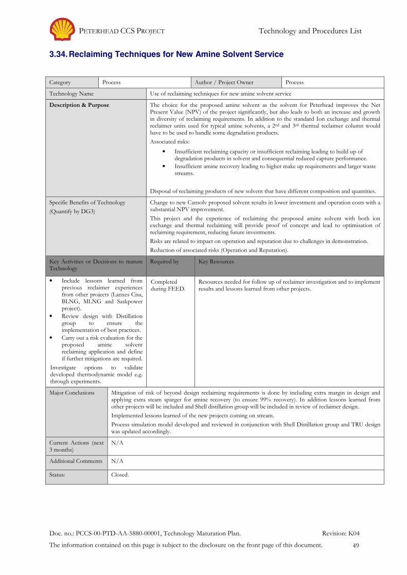
PETERHEAD CCS PROJECT Technology and Procedures List
Doc. no.: PCCS-00-PTD-AA-5880-00001, Technology Maturation Plan. Revision: K04
The information contained on this page is subject to the disclosure on the front page of this document. 49
3.34. Reclaiming Techniques for New Amine Solvent Service
Category Process Author / Project Owner Process
Technology Name Use of reclaiming techniques for new amine solvent service
Description & Purpose The choice for the proposed amine solvent as the solvent for Peterhead improves the Net Present Value (NPV) of the project significantly, but also leads to both an increase and growth in diversity of reclaiming requirements. In addition to the standard Ion exchange and thermal reclaimer units used for typical amine solvents, a 2nd and 3rd thermal reclaimer column would have to be used to handle some degradation products.
Associated risks:
• Insufficient reclaiming capacity or insufficient reclaiming leading to build up of degradation products in solvent and consequential reduced capture performance.
• Insufficient amine recovery leading to higher make up requirements and larger waste streams.
Disposal of reclaiming products of new solvent that have different composition and quantities.
Specific Benefits of Technology
(Quantify by DG3)
Change to new Cansolv proposed solvent results in lower investment and operation costs with a substantial NPV improvement.
This project and the experience of reclaiming the proposed amine solvent with both ion exchange and thermal reclaiming will provide proof of concept and lead to optimisation of reclaiming requirement, reducing future investments.
Risks are related to impact on operation and reputation due to challenges in demonstration.
Reduction of associated risks (Operation and Reputation).
Key Activities or Decisions to mature Technology
Required by Key Resources
• Include lessons learned from previous reclaimer experiences from other projects (Lanxes Cisa, BLNG, MLNG and Saskpower project).
• Review design with Distillation group to ensure the implementation of best practices.
• Carry out a risk evaluation for the proposed amine solvent reclaiming application and define if further mitigations are required.
Investigate options to validate developed thermodynamic model e.g. through experiments.
Completed during FEED.
Resources needed for follow up of reclaimer investigation and to implement results and lessons learned from other projects.
Major Conclusions Mitigation of risk of beyond design reclaiming requirements is done by including extra margin in design and applying extra steam sparger for amine recovery (to ensure 99% recovery). In addition lessons learned from other projects will be included and Shell distillation group will be included in review of reclaimer design.
Implemented lessons learned of the new projects coming on stream.
Process simulation model developed and reviewed in conjunction with Shell Distillation group and TRU design was updated accordingly.
Current Actions (next 3 months)
N/A
Additional Comments N/A
Status: Closed.

PETERHEAD CCS PROJECT Technology and Procedures List
Doc. no.: PCCS-00-PTD-AA-5880-00001, Technology Maturation Plan. Revision: K04
The information contained on this page is subject to the disclosure on the front page of this document. 50
3.35. Biological Treatment of Aqueous Effluent Containing Amines and Degradation Products
Category Process Author / Project Owner Process
Technology Name Biological treatment of Direct Contact Cooler (DCC), acid wash, ion exchange and SSE condensate polishing ion exchange effluent streams containing proposed solvent amines and degradation products.
Description & Purpose A number of aqueous waste streams will need to be discharged from the capture plant. Next to experience of Saskpower (alternative amine solvent) also new degradation products and amines from the use of the new proposed amine solvent need to be addressed in the biological treatment plant
A development release has been created and related tests have been performed. The test results and additional information from Basis for Design (BFD) has indicated that there are more and different degradation components which will generate effluents to be treated before discharge. The primary treatment considered is biological treatment.
SEPA requirement to investigate treatment of SSE waste water streams to demonstrate Best Available Technologies (BAT).
The key risks to be assessed are:
Acid wash effluent stream contains more and different contaminants potentially impacting the reliable performance of the waste water treatment plant.
Specific Benefits of Technology
(Quantify by DG3)
Improved understanding of the biological treatment of the direct contact cooler and acid wash waste streams, due to proposed amine solvents degradation, is essential to minimise environmental footprint and optimise operations and economics of this CCS technology.
Development of the correct and economical biological treatment for the effluent streams during BFD, and FEED is integrated and an essential part of the development of this technology.
Reduction of associated risk (operational, reputation).
Key Activities or Decisions to mature Technology
Required by Key Resources
• Implement results of proposed amine solvent biodegradation tests in design of water treatment plant.
• Assess updated requirement biological treatment.
• Implement any related biological treatment experiences from other projects (Saskpower alternative amine solvent).
• Create clear plan to handle any reputational aspects related to waste streams and their treatment/disposal.
Completed during FEED.
Resources needed to implement all actions following the Development release testing, as well as to carry out additional testing where needed.
Major Conclusions Analysis of the Power Station waste streams showed that they are similar to the ammonia-containing DCC waste stream and are of insignificant additional volume so they could be accommodated in the Capture Plant Waste Water Treatment Plant to satisfy the SEPA BAT expectations.
The use of the new proposed amine solvent results in different amine and degradation products which would be routed to the biological treatment unit via the acid wash effluent stream if this stream is to be treated on-site. Initial laboratory-scale testing indicated that the acid wash effluent containing amine compounds could be broken down in a dedicated bio-treater although the WWTP operators would have to perform complex tuning of operating parameters to get the residence time down to acceptable durations. The design completed by the Onshore FEED contractor therefore assumed inclusion of this stream and the WWTP facilities ended up far more complex and expensive than had originally been anticipated.
A review was carried out by Shell’s own water treatment specialists who concluded that the design as proposed would be very challenging to operate, would require additional dedicated operators and would inevitably result in increased downtime. A follow-up study was therefore commissioned to de-risk the WWTP design and this recommended a return to off-site disposal of the acid wash effluent and a simplified, well-tried bio-treatment process for the remaining ammonia-containing effluent streams. Direct Toxicity Assessment (DTA) of simulated treated effluent stream is required to demonstrate ecotoxicological impact on the marine environment and will be carried out in Detailed Design (included in Base Plan).

PETERHEAD CCS PROJECT Technology and Procedures List
Doc. no.: PCCS-00-PTD-AA-5880-00001, Technology Maturation Plan. Revision: K04
The information contained on this page is subject to the disclosure on the front page of this document. 51
Current Actions N/A
Additional Comments The waste streams and their potential outlets are an important part of the investigation targets for the demonstration project to optimise economics in future applications.
Status: Closed
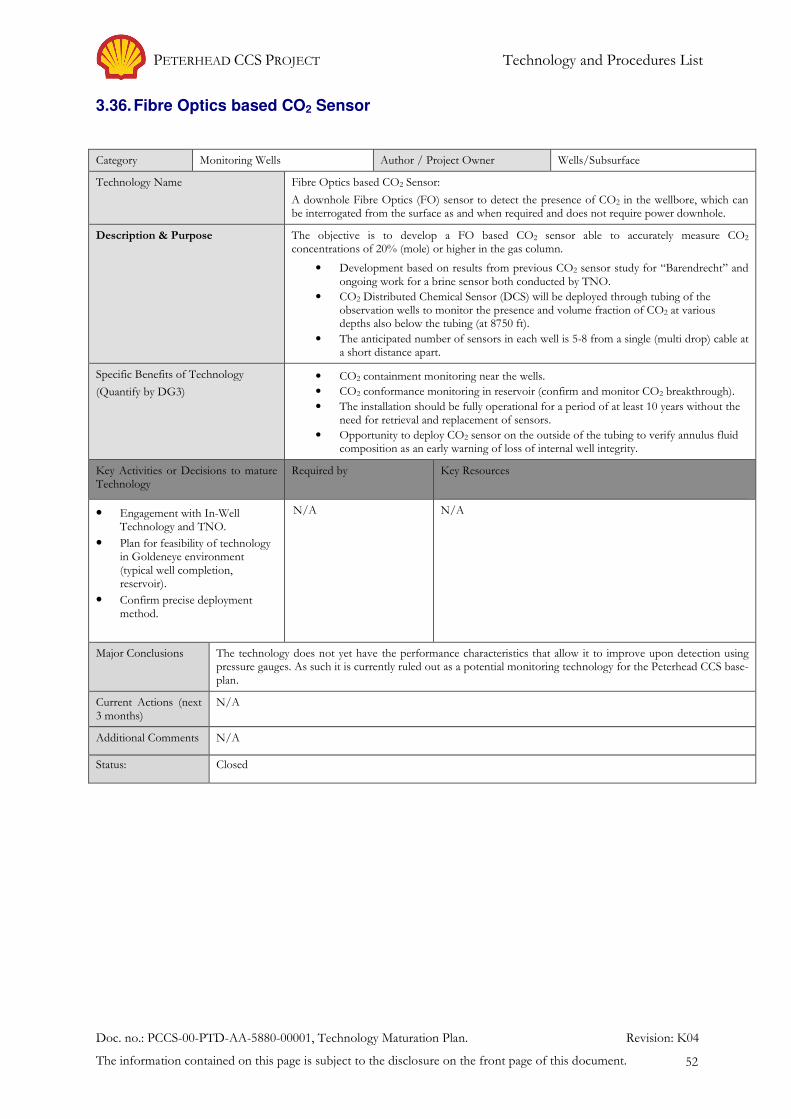
PETERHEAD CCS PROJECT Technology and Procedures List
Doc. no.: PCCS-00-PTD-AA-5880-00001, Technology Maturation Plan. Revision: K04
The information contained on this page is subject to the disclosure on the front page of this document. 52
3.36. Fibre Optics based CO2 Sensor
Category Monitoring Wells Author / Project Owner Wells/Subsurface
Technology Name Fibre Optics based CO2 Sensor:
A downhole Fibre Optics (FO) sensor to detect the presence of CO2 in the wellbore, which can be interrogated from the surface as and when required and does not require power downhole.
Description & Purpose The objective is to develop a FO based CO2 sensor able to accurately measure CO2 concentrations of 20% (mole) or higher in the gas column.
• Development based on results from previous CO2 sensor study for “Barendrecht” and ongoing work for a brine sensor both conducted by TNO.
• CO2 Distributed Chemical Sensor (DCS) will be deployed through tubing of the observation wells to monitor the presence and volume fraction of CO2 at various depths also below the tubing (at 8750 ft).
• The anticipated number of sensors in each well is 5-8 from a single (multi drop) cable at a short distance apart.
Specific Benefits of Technology
(Quantify by DG3)
• CO2 containment monitoring near the wells.
• CO2 conformance monitoring in reservoir (confirm and monitor CO2 breakthrough).
• The installation should be fully operational for a period of at least 10 years without the need for retrieval and replacement of sensors.
• Opportunity to deploy CO2 sensor on the outside of the tubing to verify annulus fluid composition as an early warning of loss of internal well integrity.
Key Activities or Decisions to mature Technology
Required by Key Resources
• Engagement with In-Well Technology and TNO.
• Plan for feasibility of technology in Goldeneye environment (typical well completion, reservoir).
• Confirm precise deployment method.
N/A N/A
Major Conclusions The technology does not yet have the performance characteristics that allow it to improve upon detection using pressure gauges. As such it is currently ruled out as a potential monitoring technology for the Peterhead CCS base-plan.
Current Actions (next 3 months)
N/A
Additional Comments N/A
Status: Closed
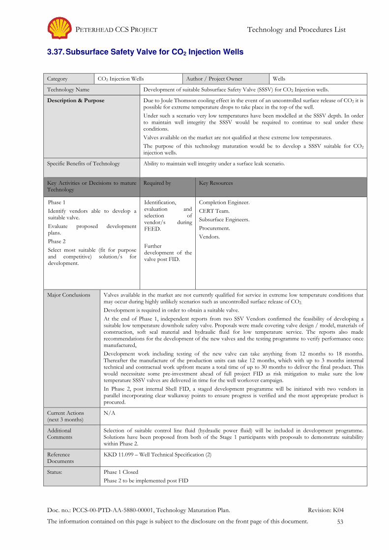
PETERHEAD CCS PROJECT Technology and Procedures List
Doc. no.: PCCS-00-PTD-AA-5880-00001, Technology Maturation Plan. Revision: K04
The information contained on this page is subject to the disclosure on the front page of this document. 53
3.37. Subsurface Safety Valve for CO2 Injection Wells
Category CO2 Injection Wells Author / Project Owner Wells
Technology Name Development of suitable Subsurface Safety Valve (SSSV) for CO2 Injection wells.
Description & Purpose Due to Joule Thomson cooling effect in the event of an uncontrolled surface release of CO2 it is possible for extreme temperature drops to take place in the top of the well.
Under such a scenario very low temperatures have been modelled at the SSSV depth. In order to maintain well integrity the SSSV would be required to continue to seal under these conditions.
Valves available on the market are not qualified at these extreme low temperatures.
The purpose of this technology maturation would be to develop a SSSV suitable for CO2 injection wells.
Specific Benefits of Technology Ability to maintain well integrity under a surface leak scenario.
Key Activities or Decisions to mature Technology
Required by Key Resources
Phase 1
Identify vendors able to develop a suitable valve.
Evaluate proposed development plans.
Phase 2
Select most suitable (fit for purpose and competitive) solution/s for development.
Identification, evaluation and selection of vendor/s during FEED.
Further development of the valve post FID.
Completion Engineer.
CERT Team.
Subsurface Engineers.
Procurement.
Vendors.
Major Conclusions Valves available in the market are not currently qualified for service in extreme low temperature conditions that may occur during highly unlikely scenarios such as uncontrolled surface release of CO2.
Development is required in order to obtain a suitable valve.
At the end of Phase 1, independent reports from two SSV Vendors confirmed the feasibility of developing a suitable low temperature downhole safety valve. Proposals were made covering valve design / model, materials of construction, soft seal material and hydraulic fluid for low temperature service. The reports also made recommendations for the development of the new valves and the testing programme to verify performance once manufactured,
Development work including testing of the new valve can take anything from 12 months to 18 months. Thereafter the manufacture of the production units can take 12 months, which with up to 3 months internal technical and contractual work upfront means a total time of up to 30 months to deliver the final product. This would necessitate some pre-investment ahead of full project FID as risk mitigation to make sure the low temperature SSSV valves are delivered in time for the well workover campaign.
In Phase 2, post internal Shell FID, a staged development programme will be initiated with two vendors in parallel incorporating clear walkaway points to ensure progress is verified and the most appropriate product is procured.
Current Actions (next 3 months)
N/A
Additional Comments
Selection of suitable control line fluid (hydraulic power fluid) will be included in development programme. Solutions have been proposed from both of the Stage 1 participants with proposals to demonstrate suitability within Phase 2.
Reference Documents
KKD 11.099 – Well Technical Specification (2)
Status: Phase 1 Closed
Phase 2 to be implemented post FID

PETERHEAD CCS PROJECT Technology and Procedures List
Doc. no.: PCCS-00-PTD-AA-5880-00001, Technology Maturation Plan. Revision: K04
The information contained on this page is subject to the disclosure on the front page of this document. 54
3.38. Pressure Control Equipment for Well Intervention
Category CO2 Injection Wells Author / Project Owner Wells
Technology Name Development of pressure control equipment for well intervention in CO2 wells.
Description & Purpose Due to Joule Thomson cooling effect during a surface release of CO2 low temperature will affect the functionality of the intervention surface rig up and pressure control equipment.
To mitigate this procedural and/or equipment modifications may be required.
Specific Benefits of Technology Ability to safely and effectively intervene (slickline/e-line) in a CO2 injection well.
Key Activities or Decisions to mature Technology
Required by Key Resources
Identify vendors able to develop suitable equipment.
OLGA modelling required to evaluate the extent of cooling.
Hold workshop to review with subject matter experts.
Evaluate proposed development plans leading to ALARP demonstrations.
Document decisions.
Post FID embark upon development.
Study and documenting results/way forward during FEED phase. Development post FID.
Completion and Intervention Engineer.
CERT Team.
Subsurface Engineer.
Vendors.
Major Conclusions Current intervention (surface rig up and pressure control) equipment is not qualified/rated to the extreme low temperature conditions that may occur during a surface release of CO2.
Procedural changes will help maintain the temperature conditions within the equipment specification; however some development may be required to certain components to reduce the lower temperature limitations.
Current Actions (next 3 months)
Collate response from intervention service providers and equipment manufactures.
Agree and document way forward.
Additional Comments
N/A
Reference Documents
KKD 11.099 – Well Technical Specification (2).
Status: To be evaluated and developed post FID.
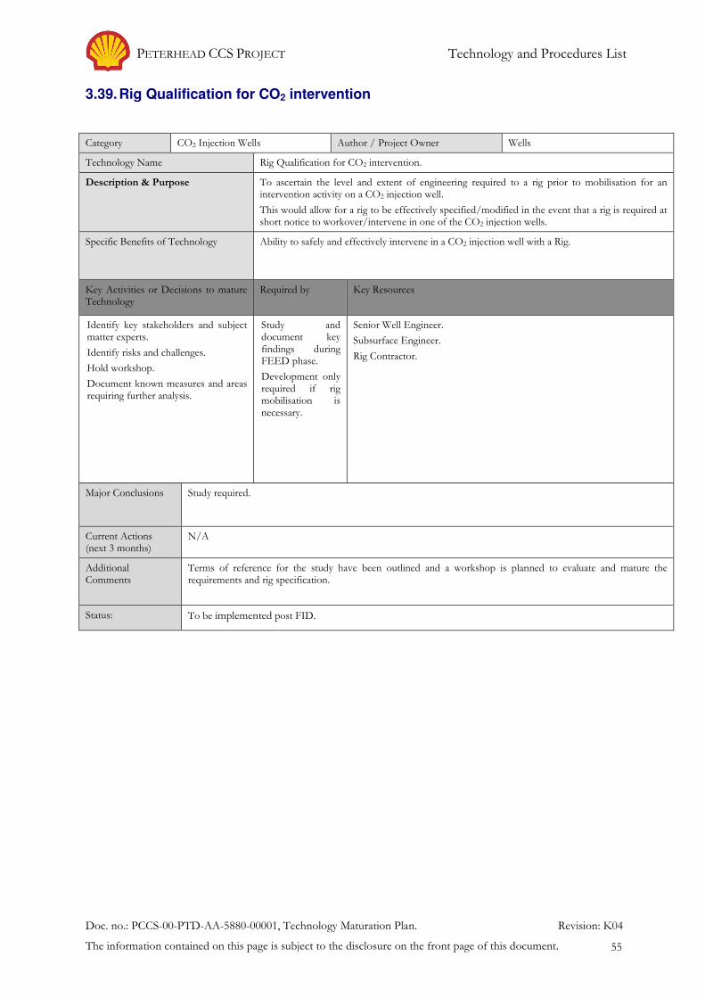
PETERHEAD CCS PROJECT Technology and Procedures List
Doc. no.: PCCS-00-PTD-AA-5880-00001, Technology Maturation Plan. Revision: K04
The information contained on this page is subject to the disclosure on the front page of this document. 55
3.39. Rig Qualification for CO2 intervention
Category CO2 Injection Wells Author / Project Owner Wells
Technology Name Rig Qualification for CO2 intervention.
Description & Purpose To ascertain the level and extent of engineering required to a rig prior to mobilisation for an intervention activity on a CO2 injection well.
This would allow for a rig to be effectively specified/modified in the event that a rig is required at short notice to workover/intervene in one of the CO2 injection wells.
Specific Benefits of Technology Ability to safely and effectively intervene in a CO2 injection well with a Rig.
Key Activities or Decisions to mature Technology
Required by Key Resources
Identify key stakeholders and subject matter experts.
Identify risks and challenges.
Hold workshop.
Document known measures and areas requiring further analysis.
Study and document key findings during FEED phase.
Development only required if rig mobilisation is necessary.
Senior Well Engineer.
Subsurface Engineer.
Rig Contractor.
Major Conclusions Study required.
Current Actions (next 3 months)
N/A
Additional Comments
Terms of reference for the study have been outlined and a workshop is planned to evaluate and mature the requirements and rig specification.
Status: To be implemented post FID.
PETERHEAD CCS PROJECT Technology and Procedures List
Doc. no.: PCCS-00-PTD-AA-5880-00001, Technology Maturation Plan. Revision: K04
The information contained on this page is subject to the disclosure on the front page of this document. 56
3.40. Tubing Material Selection
Category CO2 Injection Wells Author / Project Owner Wells
Technology Name Tubing Material Selection.
Description & Purpose The tubing material above the Subsurface Safety Valve may be exposed to low temperature excursions during highly unlikely uncontrolled release scenarios. In order to maintain well integrity under these scenarios, material with adequate low temperature properties is required.
The current plan employs the use of Alloy 825 material. This study is to evaluate the suitability of Super 13Cr in place of Alloy 825 and thereby realise a cost saving.
Specific Benefits of Technology Cost Saving.
Key Activities or Decisions to mature Technology
Required by Key Resources
Obtain finite element analysis (FEA) of thread connection from Oil County Tubular Goods supplier.
Review Crack Tip Opening Displacement (CTOD) data of the specimen material.
Review Charpy impact test data at low temperatures.
Carry out fracture mechanics study.
Build above information into an engineering criticality assessment to demonstrate material suitability.
Study and document results and build into forward plan.
Post FID.
Completion Engineer.
Subsurface Engineer.
Fracture Mechanics.
Materials Engineer.
Vendors.
Major Conclusions Study required.
Current Actions (next 3 months)
Engage with vendor to obtain all relevant information. Conduct study and document results.
Additional Comments
N/A
Status: To be implemented post FID.
PETERHEAD CCS PROJECT Technology and Procedures List
Doc. no.: PCCS-00-PTD-AA-5880-00001, Technology Maturation Plan. Revision: K04
The information contained on this page is subject to the disclosure on the front page of this document. 57
3.41. Impact of Contaminants in CO2 Stream
Category Process Author / Project Owner Process
Technology Name Impact of Contaminants in CO2 Stream
Description & Purpose The performance testing of Cansolv Solvent DC201 at the Test Centre Mongstad (TCM) revealed the presence of small quantities of amine degradation products in the captured CO2 stream. These contaminants will pass through the piping components, oxygen removal reactor, molecular sieve dehydration units and the internally-coated pipeline on the way to the storage reservoir at Goldeneye. Whilst there is no knowledge of any adverse side effects of the newly identified contaminants, testing of material compatibility is planned for the start of the Execute Phase to mitigate any residual risk.
This item is linked to the following sections in this Technology Maturation Plan:
TMP Item 3.3 CO2 Vapour / Liquid Equilibrium Data
TMP Item 3.5 Testing of Goldeneye Pipeline Internal Epoxy Coating
TMP Item 3.6 Assessment of Effect of Dense Phase CO2 on Non-Metallic (Elastomer) Materials
TMP Item 3.16 Pitting of 13% Cr Tubing Material
TMP Item 3.32 Catalytic Removal of Oxygen from CO2
TMP Item 3.33 Molecular Sieves for Dehydration in CO2 Service
Specific Benefits of Technology Quantification / reduction of possible threat to plant performance / operability / operational efficiency.
Key Activities or Decisions to mature Technology
Required by Key Resources
Consult with Materials TAs and derive recommendations for testing requirements against each of the areas of perceived vulnerability.
Identify suitable test locations and execute agreed testing plans.
Update materials specifications for at risk equipment if applicable.
Study and document results and build into forward plan post FID.
Process Engineer
Materials and Corrosion Specialist
Third Party Test Facilities
Major Conclusions Significant adverse effects are not anticipated but testing and results to be expedited early in Detailed Design.
Current Actions (next 3 months)
See Key Activities or Decisions to mature Technology
Additional Comments
None
Status: To be implemented post FID.

PETERHEAD CCS PROJECT Conclusions
Doc. no.: PCCS-00-PTD-AA-5880-00001, Technology Maturation Plan. Revision: K04
The information contained on this page is subject to the disclosure on the front page of this document. 58
4. Conclusions
The technologies which require further development for successful execution of the Peterhead CCS project have been identified initially in the pre-FEED phase and have been supplemented with new items during the FEED phase. Of the 41 technologies listed in the maturation plan, thirty two have been closed to date and nine will be addressed in the Execute Phase post FID. There do not appear to be any ‘show-stoppers’ amongst the technologies still to be matured, both in terms of development and schedule. However it must be appreciated that due to the ‘First of a Kind’ nature of the Peterhead CCS project, certain risks cannot be eliminated and will need to be mitigated as far as reasonably practicable.
The Technology Maturation Plan will be periodically updated to address any newly identified additional technology requirements or to recognise the completion of the maturation process for each technology currently under consideration.

PETERHEAD CCS PROJECT References – Bibliography
Doc. no.: PCCS-00-PTD-AA-5880-00001, Technology Maturation Plan. Revision: K04
The information contained on this page is subject to the disclosure on the front page of this document. 59
5. References – Bibliography
1. Spadeadam, Reports. [Online] DNV GL. https://www.dnvgl.com/oilgas/innovation-development/joint-industry-projects/co2pipetrans.html.
2. PCCS-05-PT-ZW-7770-00001, KKD 11.099. Well Technical Specification.
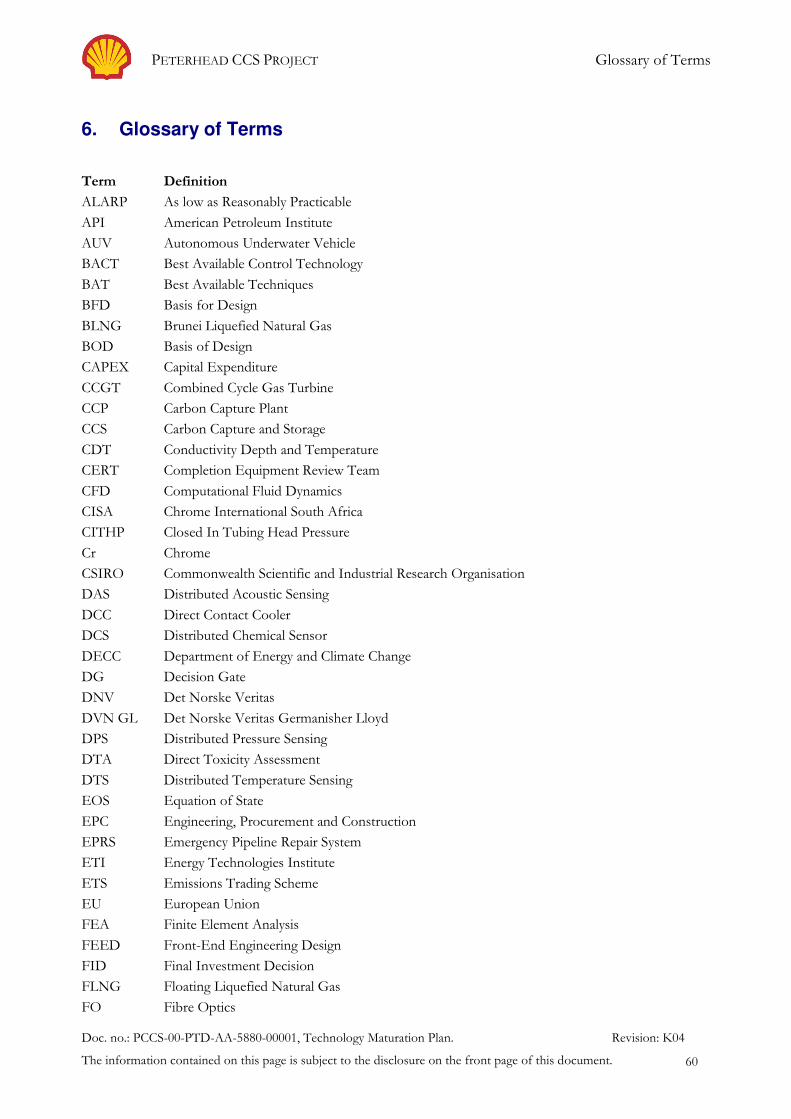
PETERHEAD CCS PROJECT Glossary of Terms
Doc. no.: PCCS-00-PTD-AA-5880-00001, Technology Maturation Plan. Revision: K04
The information contained on this page is subject to the disclosure on the front page of this document. 60
6. Glossary of Terms
Term Definition
ALARP As low as Reasonably Practicable
API American Petroleum Institute
AUV Autonomous Underwater Vehicle
BACT Best Available Control Technology
BAT Best Available Techniques
BFD Basis for Design
BLNG Brunei Liquefied Natural Gas
BOD Basis of Design
CAPEX Capital Expenditure
CCGT Combined Cycle Gas Turbine
CCP Carbon Capture Plant
CCS Carbon Capture and Storage
CDT Conductivity Depth and Temperature
CERT Completion Equipment Review Team
CFD Computational Fluid Dynamics
CISA Chrome International South Africa
CITHP Closed In Tubing Head Pressure
Cr Chrome
CSIRO Commonwealth Scientific and Industrial Research Organisation
DAS Distributed Acoustic Sensing
DCC Direct Contact Cooler
DCS Distributed Chemical Sensor
DECC Department of Energy and Climate Change
DG Decision Gate
DNV Det Norske Veritas
DVN GL Det Norske Veritas Germanisher Lloyd
DPS Distributed Pressure Sensing
DTA Direct Toxicity Assessment
DTS Distributed Temperature Sensing
EOS Equation of State
EPC Engineering, Procurement and Construction
EPRS Emergency Pipeline Repair System
ETI Energy Technologies Institute
ETS Emissions Trading Scheme
EU European Union
FEA Finite Element Analysis
FEED Front-End Engineering Design
FID Final Investment Decision
FLNG Floating Liquefied Natural Gas
FO Fibre Optics
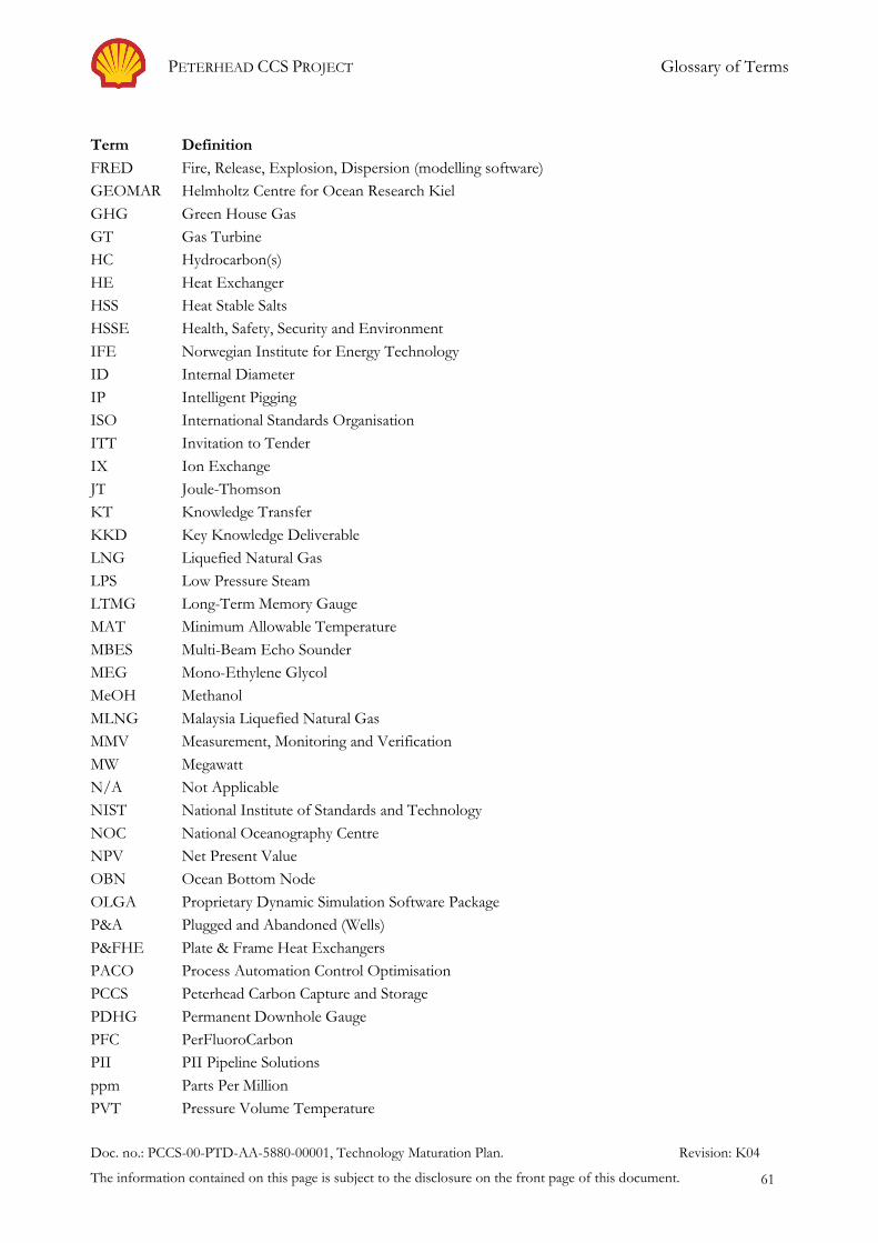
PETERHEAD CCS PROJECT Glossary of Terms
Doc. no.: PCCS-00-PTD-AA-5880-00001, Technology Maturation Plan. Revision: K04
The information contained on this page is subject to the disclosure on the front page of this document. 61
Term Definition
FRED Fire, Release, Explosion, Dispersion (modelling software)
GEOMAR Helmholtz Centre for Ocean Research Kiel
GHG Green House Gas
GT Gas Turbine
HC Hydrocarbon(s)
HE Heat Exchanger
HSS Heat Stable Salts
HSSE Health, Safety, Security and Environment
IFE Norwegian Institute for Energy Technology
ID Internal Diameter
IP Intelligent Pigging
ISO International Standards Organisation
ITT Invitation to Tender
IX Ion Exchange
JT Joule-Thomson
KT Knowledge Transfer
KKD Key Knowledge Deliverable
LNG Liquefied Natural Gas
LPS Low Pressure Steam
LTMG Long-Term Memory Gauge
MAT Minimum Allowable Temperature
MBES Multi-Beam Echo Sounder
MEG Mono-Ethylene Glycol
MeOH Methanol
MLNG Malaysia Liquefied Natural Gas
MMV Measurement, Monitoring and Verification
MW Megawatt
N/A Not Applicable
NIST National Institute of Standards and Technology
NOC National Oceanography Centre
NPV Net Present Value
OBN Ocean Bottom Node
OLGA Proprietary Dynamic Simulation Software Package
P&A Plugged and Abandoned (Wells)
P&FHE Plate & Frame Heat Exchangers
PACO Process Automation Control Optimisation
PCCS Peterhead Carbon Capture and Storage
PDHG Permanent Downhole Gauge
PFC PerFluoroCarbon
PII PII Pipeline Solutions
ppm Parts Per Million
PVT Pressure Volume Temperature

PETERHEAD CCS PROJECT Glossary of Terms
Doc. no.: PCCS-00-PTD-AA-5880-00001, Technology Maturation Plan. Revision: K04
The information contained on this page is subject to the disclosure on the front page of this document. 62
Term Definition
R&D Research and Development
REACH Registration, Evaluation, Authorisation and restriction of CHemicals
ROV Remotely Operated Vehicle
SEPA Scottish Environmental Protection Agency
SSE Scottish & Southern Energy
SSSV Subsurface Safety Valve
STEMM-CCS Multi-institution EU project focused on environmental monitoring of CCS reservoirs
TA Technical Assurers
TBD To Be Determined
TMP Technology Maturation Plan
TNO Netherlands Organisation for Applied Scientific Research
TRL Technical Readiness Level
TRP Technical Realisation Process
TRU Thermal Reclaimer Unit
VSP Vertical Seismic Profiling
WE Well Engineer
WPBHE Welded Plate Block Heat Exchangers
WWTP Waste Water Treatment Plant
Xe Xenon