Embed Size (px)
Citation preview
Clays and Clay Minerals, Vol. 49, No. 1. 123, 2001.
PERTURBATIVE THEORY OF MICA POLYTYPISM. ROLE OF THE M2 LAYER IN THE FORMATION OF I N H O M O G E N E O U S POLYTYPES
MASSIMO NESPOLO
Japan Science and Technology Corporation, National Institute for Research in Inorganic Materials, 1-1 Namiki, Tsukuba-shi, Ibaraki 305~)044, Japan
Abs t r ac t - -A new model is proposed to explain, within the framework of the theory of spiral growth of Frank, the formation on inhomogeneous mica polytypes. This model relates the interaction and cooperative growth of two components (spirals and/or crystals) to produce a new stacking sequence. Depending on the relative orientation between the two components, a mismatch of the interlayer positions occurs, which is compensated through either a growth defect or a crystallographic slip at the octahedral (O) sheet. Both these adjustments transform the M1 layer into the M2 layer. These two types of layers have the same chemical composition but differ in cation distribution in the O sheet. The coalescence and cooperative growth of crystals occurs in fluid-rich environments and is most frequent in druses and volcanic fumaroles. These environments favor the inhomogeneous polytypes, especially those with complex stacking sequenc- es. In addition, the M1 -~ M2 transformation is most probable in micas with an oxybiotitic composition, where the removal of the OH dipole strengthens the interlayer bonding and the presence of high-charge cations destabilizes the O sheet. Three examples of inhomogeneous polytypes of titaniferous oxybiotite from Ruiz Peak (a volcanic environment where many inhomogeneous polytypes have been reported) are presented.
Key Words--Crysta l Growth, Long-Period Polytypes, Mica, Polytypism.
~ T R O D U C T I O N
Micas are phyl los i l ica tes bui l t by a 2:1 or T-O-T layer, hence fo r th cal led " M l aye r " , (Figures 1 and 2) wi th in te r layer ca t ions be tween adjacent layers. In the ideal s t ructure (Pauling, 1930), the in ter layer cat ions are in hexagona l pr ismat ic coordinat ion , wi th 12 near- e s t -ne ighbor oxygen atoms, six f rom each M layer, and the layer s y m m e t r y is P(6)mm ( layer-group nota t ion after Dornberger -Schi f f , 1959). The mos t re levan t s tructural d is tor t ion occur r ing in the real layer is the ro ta t ion of the te t rahedra in the T sheets about the normal to the layer, by an angle that depends upon crys ta l chemis t ry and on t empera tu re and pressure (Takeda and Moros in , 1975; Cat t i et al., 1989). Con- sequently, the s y m m e t r y of the T sheets is r educed to P ( 3 ) l m and the 12 oxygen a toms a round the inter layer ca t ion separate into six nea res t -ne ighbors and six next- neares t ne ighbors : The site hos t ing the in ter layer cat- ion b e c o m e s a t r igonal (cons ider ing the neares t six ox- ygen a toms) or d i t r igonal (cons ider ing all 12 oxygen a toms) an t ipr i sm for 2n • 60 ~ ro ta t ions of the layers, or a t r igonal /d i t r igonal p r i sm for (2n + 1) x 60 ~ ro- ta t ions (n integer, 0 -< n --< 5). The lat ter coord ina t ion po lyhed ron is energet ica l ly less favorable , because the basal oxygen a toms are super imposed in the (001) pro- jec t ion.
In the in ter layer reg ion be t w een two adjacent M lay- ers, m o n o v a l e n t and, less frequently, d iva len t cat ions occur. Po iy typ i sm arises f rom the s tacking of the M layer a long the c axis: the geomet r ica l opera t ion re- la t ing pairs of layers is a two-fo ld axis in the inter lay- er, and adjacent layers resul t ro ta ted by n X 60 ~ (0 --<
n <-- 5) about c*. Poly types in wh ich the pos i t ion o f any layer relat ive to the others and the t rans i t ion f rom it to the adjacent ones are the same or equ iva len t for all layers are t e rmed homogeneous (Zvyag in , 1988). H o m o g e n e o u s poly types have success ive M layers ro- ta ted a lways by the same angle, apart f r om the sign, and co r respond to the so-cal led " s i m p l e p o l y m o r p h s " in Smi th and Yoder (1956). By us ing Ramsde l l (1947) nota t ion, h o m o g e n e o u s po ly types are ident i f ied as 1M, 2M~, 3T, 2M2, 2 0 , and 6 H ( symbols for po ly type sym- me t ry accord ing to Gu in i e r et al., 1984). The remain - ing poly types are t e rmed inhomogeneous and corre- spond to the " c o m p l e x p o l y m o r p h s " in Smi th and Yoder (1956). Mica poly types are then sui tably clas- sified into three kinds, depend ing on the geomet r i ca l equ iva lence o f layer pairs (I)urovi~ et al., 1984; Nes- polo, 1999): 1) subfamily-A polytypes: success ive lay- ers are ro ta ted by 2n X 60 ~ only; 2) subfamily-B po- lytypes: success ive layers are ro ta ted by (2n + 1) x 60 ~ only; 3) mixed-rotation polytypes: success ive lay- ers are rota ted by bo th 2n X 60 ~ and (2n + 1) X 60 ~ (in all cases 0 --< n ----- 5) (Table 1). M o s t of the poly- types repor ted to date be long to subfami ly A. In sub- fami ly B, only 2M2 and 2 0 are known, the lat ter be ing rare. A few examples of mixed- ro ta t ion po ly types have b e e n reported: 4AI (Takeda, 1967), 3M2 and 6M1 (Bai ley and Christ ie , 1978; Rule et at., 1987), 36A1 ( K o g u r e and Nespo lo , 1999a) , and a d i s o r d e r e d m i x e d - r o t a t i o n s e q u e n c e ( K o g u r e and N e s p o l o , 1999b). As shown by Ross et al. (1966), a por t ion o f the s tacking sequence o f the i n h o m o g e n e o u s mica po- ly types co inc ides wi th one or more per iods of one o f
Copyright �9 2001, The Clay Minerals Society 1
2 Nespolo Clays and Clay Minerals
Figure 1. The structure of 1M mica projected along the b axis. Closed and open small circles represent octahedral sites M1 and M2, respectively. Large open circles are interlayer cations. The period along c is compressed. Inset in the top-right corner: axes (a, b) of the space-fixed reference (Cj setting) and of the structure-related references in the six possible orientations (a~- a 6 ) , and corresponding Z symbols. The direction of the intralayer displacement (ID) vector and of its (001) projection (Z vector) is indicated by Z symbol i (i = 1-6) when the a~ axis of the corresponding half-layer is parallel to the space fixed a axis (modified after Nespolo et al., 1999a).
the three h o m o g e n e o u s sub fami ly -A polytypes , name- ly 1M, 2M~, and 3T, s imilar ly to wha t occurs in SiC polytypes . For this reason, these three poly types are ca l led bas ic s t ruc tures (Baronne t and Kang, 1989). The r ema in ing por t ion of the s tacking sequence o f an i n h o m o g e n e o u s po ly type represents a dev ia t ion in the s tacking sequence of the basic polytypes. I nhomoge - neous po ly types are thus said to be long to one of the three s t ruc tura l ser ies represen ted by the basic struc- tures (Ross et al., 1966; Takeda and Ross, 1995).
The purpose of the present paper is to in t roduce a model to exp la in in a s imple way, wi th in the f rame- work o f the spiral g rowth m e c h a n i s m of F rank (1949, 1951 a), the appearance o f complex s tacking sequences that canno t be accoun ted for by previous models . The key aspect of this model is the d is t inc t ion be tween two k inds of layers, M 1 and M2, wh ich differ for the cat- ion d is t r ibut ion in the O sheet. Each layer can be t rans- fo rmed into the o ther th rough a g rowth defect or a c rys ta l lograph ic slip at the oc tahedra l sheet. A b r i e f
s u m m a r y of the present knowledge is necessa ry to in- t roduce the new model .
S T R U C T U R A L C O N T R O L
Smi th and Yoder (1956) in t roduced the concep t of s t ruc tura l con tro l to correlate the obse rved f requency of mica poly types wi th chemica l composi t ion . Bas ic cons idera t ions for structural control are s u m m a r i z e d as fo l lows (Gtiven, 1971; Baronne t , 1980). 1) In the ab- sence of structural control , the f requency of occur- rence of a poly type wi th a g iven n u m b e r N of layers shou ld be a s imple func t ion o f the n u m b e r of layers in the repea t unit . This hypothes i s contras ts wi th ex- per imenta l observa t ions . 2) Structural cont ro l is relat- ed to crysta l chemis t ry and to the geomet r ica l distor- t ions of the layer, especia l ly of the O sheet. Dis tor t ions l imi t the s tacking poss ibi l i t ies and, therefore, the for- ma t ion of a great n u m b e r of polytypes. Dis tor t ions are s t ronger in pure d ioc tahedra l micas , lower in Li - r ich t r ioctahedral micas , and still l ower in L i -poor tr iocta-
Vol. 49, No. 1, 2001 Role of the M2 layer in inhomogeneous mica polytypes 3
a 2
~ a l ~ 5
a,a 3
~ a4
~ a5
a 6
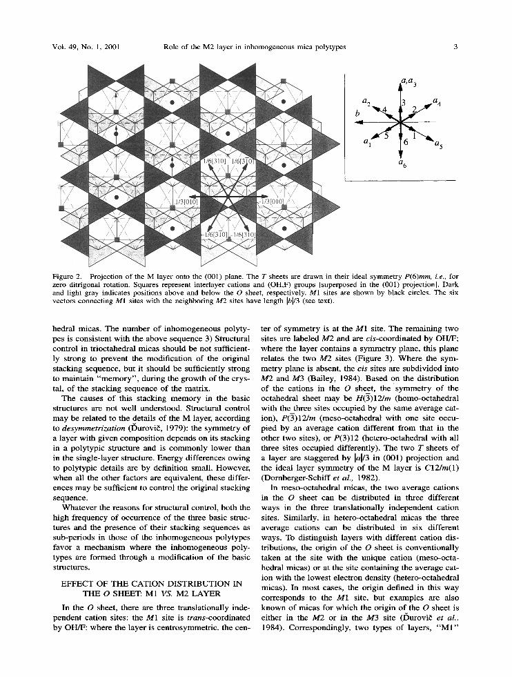
Figure 2. Projection of the M layer onto the (001) plane. The T sheets are drawn in their ideal symmetry P(6)mm, i.e., for zero ditrigonal rotation. Squares represent interlayer cations and (OH,F) groups [superposed in the (001) projection]. Dark and light gray indicates positions above and below the O sheet, respectively. M1 sites are shown by black circles. The six vectors connecting M1 sites with the neighboring M2 sites have length Ibl/3 (see text).
hedral micas. The number of inhomogeneous polyty- pes is consistent with the above sequence 3) Structural control in trioctahedral micas should be not sufficient- ly strong to prevent the modificat ion of the original stacking sequence, but it should be sufficiently strong to maintain " m e m o r y " , during the growth of the crys- tal, of the stacking sequence of the matrix.
The causes o f this stacking m e m o r y in the basic structures are not well understood. Structural control may be related to the details o f the M layer, according to desymmetrization (I)urovi6, 1979): the symmetry of a layer with g iven composi t ion depends on its stacking in a polytypic structure and is commonly lower than in the single-layer structure. Energy differences owing to polytypic details are by definition small. However , when all the other factors are equivalent, these differ- ences may be sufficient to control the original stacking sequence.
Whatever the reasons for structural control, both the high f requency of occurrence of the three basic struc- tures and the presence of their stacking sequences as sub-periods in those o f the inhomogeneous polytypes favor a mechanism where the inhomogeneous poly- types are formed through a modif icat ion of the basic structures.
E F F E C T OF T H E C A T I O N D I S T R I B U T I O N IN T H E O SHEET: M1 VS. M2 L A Y E R
In the O sheet, there are three translationally inde- pendent cation sites: the M1 site is trans-coordinated by OH/F: where the layer is centrosymmetric, the cen-
ter o f symmetry is at the M1 site. The remaining two sites are labeled M2 and are cis-coordinated by OH/F; where the layer contains a symmetry plane, this plane relates the two M2 sites (Figure 3). Where the sym- metry plane is absent, the cis sites are subdivided into M2 and M3 (Bailey, 1984). Based on the distribution of the cations in the O sheet, the symmet ry o f the octahedral sheet may be H(-3)12/m (homo-octahedral with the three sites occupied by the same average cat- ion), P(3)12/m (meso-octahedral with one site occu- pied by an average cation different f rom that in the other two sites), or P(3)12 (hetero-octahedral with all three sites occupied differently). The two T sheets of a layer are staggered by la[/3 in (001) project ion and the ideal layer symmetry of the M layer is C12/m(1) (Domberger -Schi f f et aL, 1982).
In meso-octahedral micas, the two average cations in the O sheet can be distributed in three different ways in the three translationally independent cation sites. Similarly, in hetero-octahedral micas the three average cations can be distributed in six different ways. To distinguish layers with different cation dis- tributions, the origin of the O sheet is convent ional ly taken at the site with the unique cation (meso-octa- hedral micas) or at the site containing the average cat- ion with the lowest electron density (hetero-octahedral micas). In most cases, the origin defined in this way corresponds to the M1 site, but examples are also known of micas for which the origin o f the O sheet is either in the M2 or in the M3 site (I)urovi~ et al., 1984). Correspondingly, two types of layers, " M I "
4 Nespolo Clays and Clay Minerals
Table 1. Classification of mica polytypes in terms of the relative rotations between layers, and corresponding parity rules for Z and RTW symbols.
Z symbols RTW symbols Relative rotations between layers Kind of polytype
Same parity (either all odd or all even)
Alternating parity
Mixed, non-alternating parity
all-even 0 ~ (1M) 120 ~ and 240 ~ (2Mr) 120 ~ or 240 ~ (3T) 2n • 60 ~ with more than
one value of n all-odd 180 ~ (20)
60 ~ and 300 ~ (2Mz) I 60 ~ or 300 ~ (6H) (2n + 1) • 60 ~ with more than
one value of n both odd and even both 2n • 60 ~ and 2n • 60 ~
homogeneous subfamily A (basic structures)
inhomogeneous subfamily A
homogenous subfamily B
inhomogeneous subfamily B mixed rotation
(inhomogeneous)
t Baronnet and Kang (1989) included also 2Mz in their definition of basic structures, foreseeing the possible occurrence of inhomogeneous polytypes based on the stacking sequence of this polytype and belonging thus to the 2M2 structural series. To date no example has been reported.
Z vectors
SY vector
b __.
a 10] [3]-01
~ [1T0]
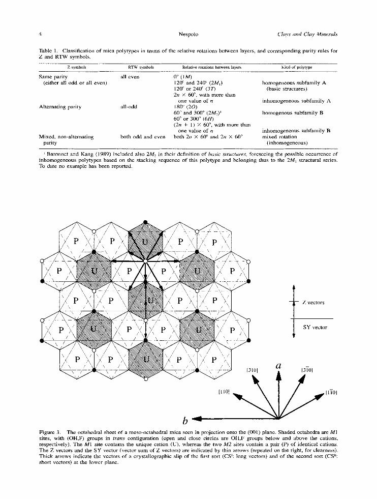
Figure 3. The octahedral sheet of a meso-octahedral mica seen in projection onto the (001) plane. Shaded octahedra are M1 sites, with (OH,F) groups in trans configuration (open and close circles are OH,F groups below and above the cations, respectively). The M1 site contains the unique cation (U), whereas the two M2 sites contain a pair (P) of identical cations. The Z vectors and the SY vector (vector sum of Z vectors) are indicated by thin arrows (repeated on the right, for clearness). Thick arrows indicate the vectors of a crystallographic slip of the first sort (CS~: long vectors) and of the second sort (CSn: short vectors) at the lower plane.
Vol. 49, No. 1, 2001 Role of the M2 layer in inhomogeneous mica polytypes 5
SYvector
Z vectors
~o1 a t3ro]
[11o] ~ [ITO]
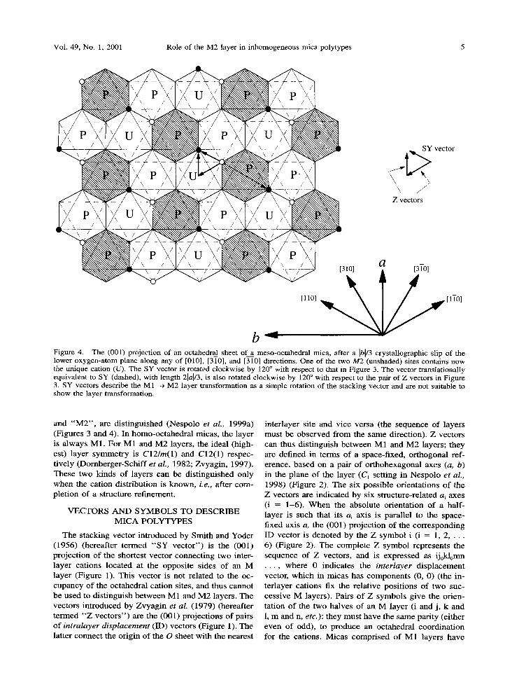
b Figure 4. The (001) projection of an octahedral sheet of__a meso-octahedral mica, after a Ibl/3 crystallographic slip of the lower oxygen-atom plane along any of [010], [310], and [310] directions. One of the two M2 (unshaded) sites contains now the unique cation (U). The SY vector is rotated clockwise by 120 ~ with respect to that in Figure 3. The vector translationally equivalent to SY (dashed), with length 21al/3, is also rotated clockwise by 120 ~ with respect to the pair of Z vectors in Figure 3. SY vectors describe the M1 --~ M2 layer transformation as a simple rotation of the stacking vector and are not suitable to show the layer transformation.
and " M 2 " , are dist inguished (Nespolo et al., 1999a) (Figures 3 and 4). In homo-octahedral micas, the layer is always M1. For M1 and M2 layers, the ideal (high- est) layer symmetry is C12/m(1) and C12(1) respec- t ively (Dornberger-Schiff et aL, 1982; Zvyagin, 1997). These two kinds of layers can be distinguished only when the cation distribution is known, Le., after com- pletion of a structure refinement.
V E C T O R S A N D S Y M B O L S TO D E S C R I B E M I C A P O L Y T Y P E S
The stacking vector introduced by Smith and Yoder (1956) (hereafter termed " S Y vec to r" ) is the (001) projection of the shortest vector connecting two inter- layer cations located at the opposite sides of an M layer (Figure 1). This vector is not related to the oc- cupancy of the octahedral cation sites, and thus cannot be used to distinguish be tween M1 and M 2 layers. The vectors introduced by Zvyagin et al. (1979) (hereafter termed " Z vec tors" ) are the (001) projections of pairs o f intralayer displacement (ID) vectors (Figure 1). The latter connect the origin of the O sheet with the nearest
interlayer site and vice versa (the sequence of layers must be observed f rom the same direction). Z vectors can thus distinguish be tween M1 and M2 layers; they are defined in terms of a space-fixed, or thogonal ref- erence, based on a pair o f or thohexagonal axes (a, b) in the plane o f the layer (C1 setting in N e s p o l o e t al., 1998) (Figure 2). The six possible orientations o f the Z vectors are indicated by six structure-related ai axes (i = 1-6). When the absolute orientation of a half- layer is such that its ai axis is parallel to the space- fixed axis a, the (001) projection of the corresponding ID vector is denoted by the Z symbol i (i = 1, 2 . . . . 6) (Figure 2). The complete Z symbol represents the sequence of Z vectors, and is expressed as ij0kl0nm . . . . where 0 indicates the interlayer displacement vector, which in micas has components (0, 0) (the in- terlayer cations fix the relative positions of two suc- cessive M layers). Pairs of Z symbols give the orien- tation o f the two halves of an M layer (i and j , k and 1, m and n, etc.): they must have the same parity (either even of odd), to produce an octahedral coordinat ion for the cations. Micas comprised o f M1 layers have
6 Nespolo Clays and Clay Minerals
two identical Z symbols, i.e., i = j, k = 1, m = n, etc.; in this case the symbol 0 may be omitted and a shortened symbol IKM . . . is commonly adopted (Zhukhlistov et al., 1990; see Figure 1 therein). Adop- tion of the shortened Z symbolism is equivalent to describe the layer as if it is homo-octahedral, and for this reason the term homo-octahedral approximation was introduced (Nespolo et al., 1999a).
Other symbols often used to describe mica polyty- pes are the orientation-free, rotational RTW symbols (Ross et al., 1966), which express the relative rotations (mod 60 ~ between pairs of SY vectors and cannot distinguish between M1 and M2 layers. The symbol correspondence for the three kinds of polytypes de- scribed in the previous section is given in Table 1. Hereafter, the indices of axes and planes are given in the (pseudo)orthohexagonal cell. This cell coincides with the conventional cell for orthogonal polytypes, and contains three conventional cells for non-orthog- trial polytypes. Consequently, planes almost normal to (001) are indicated as (hk0).
SPIRAL GROWTH IN MICAS
Hartman and Perdok (1955) classified crystal faces into F (flat), S (stepped), and K (kinked) depending on whether they contain in the same order two or more, one, or no periodic bond chain (PBC) vectors, i.e., vectors indicating directions of strong bonding. In micas, the K faces (e.g., { 111 } in the orthohexagonal setting) are not developed as crystal faces; the F faces correspond to the (001) plane, and the S faces are nor- mal (e.g., { 100}) or inclined (e.g., {110}) to the (001) plane (see, e.g., Peacock and Ferguson, 1943). The F faces grow slowly in the direction perpendicular to the face, are large and flat, have a low surface energy, and no dangling bonds, they often contain growth-spirals. In contrast, S faces grow rapidly in the direction per- pendicular to the face, are relatively small, have a high surface energy, contain dangling bonds, and are the preferential site for the accretion of larger crystalli- zation units, e.g., already existing crystal nuclei. S fac- es are characterized by striations and a lack of growth spirals (Sunagawa and Bennema, 1982). Cleavage in micas occurs along F faces, the structure of F faces is comprised of basal oxygen atoms and interlayer cat- ions (Kogure, 1997).
The spiral-growth model is a perfect memory mech- anism repeating either the complete stacking sequence of a polytype (perfect dislocation: the pitch of the screw dislocation from which the spiral originates is a multiple of the polytype periodicity) or a part of a stacking sequence (imperfect dislocation: the pitch of the screw dislocation is a submultiple of the polytype periodicity). The presence of a stacking fault in the exposed ledge increases the number of polytypes which can form in this way (Frank, 1949, 1951a). The outcrop of a screw dislocation on the surface of a crys-
tal is the result of an increase in the crystal stress either because of thermal stresses or physical-type stresses, i.e., non-uniform distribution of impurities (Frank, 1951a).
Polytypism in binary compounds may be generally explained by considering the presence of one or more stacking faults in the exposed ledge (faulted matrix model, FMM; spiral growth of an unfaulted ledge: per- fec t matrix model, PMM) (for details see Baronnet, 1997). For micas, the PMM can explain only subfam- ily-A inhomogeneous polytypes belonging to 2M1 and 3T structural series, and the possible sequences cor- respond to RTW symbols (22),0 (2M~ structural se- ries), and (222),0 and (222)n22 (3T structural series) (Ross et al., 1966; Baronnet, 1980). The FMM intro- duces a higher degree of flexibility, without however explaining the more complex stacking sequence, which would require "singly- or multiply-faulted ex- posed ledges containing higher energy fault configu- rations" (Pandey et al., 1982), a situation with a low probability of occurrence and at variance with the starting assumptions of the FMM itself. Micas have features markedly different from those of binary com- pounds: I) they are not based on closest-packed ar- rangements: only the planes of hydroxyl groups and apical oxygen atoms follow the closest-packed topol- ogy (Pauling, 1930), and micas have a large anion- anion spacing in the plane of hydroxyl groups and api- cal oxygen atoms (Noe and Veblen, 1999); 2) layers are related by both translations and rotations; 3) basic structures include one, two, and three-layer polytypes only; and 4) the relative positions of successive layers are determined by the interlayer cations. Other factors, different from the casual presence of stacking faults in the ledge, must be considered if Frank's mechanism of spiral growth is to explain the most complex stack- ing sequences reported in micas.
RELATION BETWEEN CRYSTALLIZATION ENVIRONMENT, CRYSTAL CHEMISTRY, AND
THE OCCURRENCE OF INHOMOGENEOUS POLYTYPES
The explanation for the occurrence of long-period polytypes with a complex stacking sequence is related to a perturbation occurring during spiral growth. Well- known perturbing events include the interactions be- tween spirals present on the same crystal, between a spiral and a crystal, or between two separate crystals. The relation between these three types of interactions and the frequency of inhomogeneous polytypes can be explained in terms of crystallization environments.
During metamorphism, minerals are formed in situ by solid-solid transformation and the products occupy the space of the reactants. Spiral growth is commonly not observed on crystal surfaces (Sunagawa et al., 1975). Dioctahedral micas are typical of metamorphic rocks (Guidotti and Sassi, 1998) and thus far they are
Vol. 49, No. 1, 2001 Role of the M2 layer in inhomogeneous mica polytypes 7
not known to form inhomogeneous polytypes [the three-layer monoclinic muscovite of Axelrod and Gri- maldi (1949) is a 3T polytype (Smith and Yoder, 1956)]. Also, in synthetic samples, the occurrence of inhomogeneous polytypes in dioctahedral micas is ex- ceptional (Baronnet et al., 1976). Li-rich trioctahedral micas are typical of greisens, pegmatites, and hydro- thermal veins (Rieder et al., 1970) and are thus formed by metasomatism, through dissolution-precipitation. In these environments, crystals precipitate directly from slow-moving solutions with low supersaturation. Po- lygonal growth spirals are invariably present on their surface (Sunagawa, 1977). Some inhomogeneous po- lytypes belonging to 1M or 3T structural series were reported, and the stacking sequences were closely re- lated to those of the corresponding basic structures (Takeda, 1967; Rieder, 1970). Li-poor trioctahedral micas occur mainly in magmatic environments, and inhomogeneous polytypes were reported in both plu- tonic (Borutskiy et al. 1987; Zhukhlistov et al., 1990, 1993; Bigi and Brigatti, 1994) and volcanic rocks (Hendricks and Jefferson, 1939; Amelinckx and De- keyser, 1953; Ross et al., 1966; Takeda and Ross, 1995; Nespolo and Takeda, 1999; Kogure and Nes- polo, 1999a).
In plutonic Li-poor trioctahedral micas, the reported polytypes, even when they possess a long-period stacking sequence, are a simple modification of one of the three basic structures. Inhomogeneous polytypes With more complex stacking sequences are found in druses or in volcanic fumaroles, where crystallization occurs by post-volcanic action (e.g., Tomisaka, 1958, 1962; Ross et al., 1966): their occurrence seems thus related to the final differentiation stage of a magma, where volatile components are present as super-critical vapor phase. Experiments simulating the growth in these environments have successfully produced inho- mogeneous polytypes of fluor-phlogopite, emphasizing the role kinetics play in crystal growth (Sunagawa et al., 1968).
The main features of crystal growth in a magma and from a vapor phase can be summarized and compared as follows (Sunagawa, 1977, 1978, 1982; Sunagawa and Bennema, 1982). 1) Solid-fluid interactions are stronger during the crystallization from a melt then during precipitation from a vapor phase, for which ac- cretion of groups of atoms or ions instead of single atoms or ions is characteristic. 2) The critical super- saturation below which the spiral growth mechanism is active is much higher with growth from the vapor phase than from solutions. Growth spirals are thus more numerous and frequent in vapor growth, and much less developed in crystallization from magma. 3) The mobility of crystal nuclei and the probability to settle on larger crystals is much higher in a fluid or vapor phase than in a silicate magma. In a vapor phase, small mica crystals move freely in the open
space, like "flying magic carpets" (Sunagawa and Endo, 1971; Sunagawa and Tomura, 1976).
Free moving crystal nuclei in a fluid environment frequently come into contact with each other and oc- casionally get attached. Just before agglutinating, they adjust their mutual orientation, to form a parallel growth, a twin/allotwin or, more rarely, a plesiotwin (Sunagawa et aL, 1975; Sunagawa and Tomura, 1976) (Allotwins are the twin-like oriented crystal associa- tions of different polytypes of the same compound; see Nespolo et al., 1999b; plesiotwins are oriented crystal associations based on a large coincidence-site lattice; see Nespolo et al., 1999c). Small mica nuclei settle onto the F face of a larger mica crystal, taking a crys- tallographically identical, twinned, or inclined orien- tation relative to the host crystal, with composition plane (001), as observed in the "biotitic phlogopite" (now termed "ferrous phlogopite", Rieder et al., 1998) from druses at Mutsure-jima, Japan (Sadanaga and Tak6uchi, 1961; Sunagawa, 1964; Sunagawa and Tomura, 1976). This specimen (K6zu and Yoshiki, 1929; K6zu and Tsurumi, 1931; Tomisaka, 1958) was the object of a systematic surface study by phase-con- trast microscopy and was described as a 1M polytype (Tomisaka, 1962), but no systematic diffraction or high-resolution transmission electron microscopy (HRTEM) study was performed, and thus the sample may contain other polytypes. If the crystallites settle close to each other, they may interact through their S faces. This kind of contact eliminates two high-energy surfaces with exposed dangling bonds (one for each crystal) to form a twin with a composition plane (near- ly) normal to the (001) plane (see examples in Suna- gawa, 1964). The surface of the larger crystal where they settle may not be atomically flat and the crystal- lites will in general cover an irregularly stepped sur- face, thus producing an inclined interface. Two crys- tallites close to each other, in general, are thus rela- tively inclined. One or more screw dislocations will, therefore, arise along the boundary of two inclined crystallites which coalesce along their S faces, from which new growth ledges originate (Sunagawa et al., 1975; Tomura et al., 1979). A cooperative growth be- gins which, during its early stage, must overcome a certain degree of mismatch caused by the relative in- clination of the crystallites. As discussed below, it is through the recovery of this mismatch that an inho- mogeneous polytype with a relatively complex stack- ing sequence can form.
POLYTYPE FORMATION AND MECHANICAL STRENGTH: CRYSTALLOGRAPHIC SLIPS AND
THEIR ROLE IN THE M 1 ~ M2 TRANSFORMATION
The M layer may form initially as an M2 layer: for dioctahedral micas, this occurs when the grain crys- tallizes in conditions far from equilibrium (Zvyagin et
8 Nespolo Clays and Clay Minerals
b/3
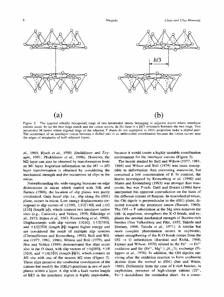
(a) (b) Figure 5. The trigonal (ideally hexagonal) tings of two tetrahedral sheets belonging to adjacent layers where interlayer cations occur. In (a) the two rings match and the cation occurs. In (b) there is a Ibl/3 mismatch between the two rings. Two successive M layers where trigonal rings of the adjacent T sheets do not superpose in (001) projection make a shifted pair. The occurrence of an interlayer cation between a shifted pair is an unfavorable coordination because the cation occurs near the edges of tetrahedra of both adjacent layers.
aL, 1985; Bloch et al., 1990; Zhukhlistov and Zvy- agin, 1991; Zhukhl is tov et aL, 1996). However , the M2 layer can also be obtained by transformation from an M1 layer. Important information on the M1 --~ M2 layer transformation is obtained by considering the mechanical strength and the occurrence of slips in the micas.
Notwithstanding the wide-ranging literature on edge dislocations in micas which started with Silk and Barnes (1960), the location of slip planes was partly overlooked. Only basal slip, i.e., slip along the (001) plane, occurs in micas. Low-energy displacements cor- respond to slip vectors of -+ [ 100], ___ 1/2[ 110], and _+ 1/2 [1]-0] (length [a[), which connect two interlayer cation sites (e.g., Caslavsky and Vedam, 1970; Etheridge et al., 1973; Bafios et al., 1983; Kronenberg et al., 1990). Displacements with slip vectors _[010] , _1/21310], and _+1/213]0] (length Ibl) require higher energy and are considered the result of mult iple slip systems (Christoffersen and Kronenberg, 1993). Bell and Wil- son (1977, 1981, 1986), Wilson and Bell (1979), and Noe and Veblen (1999) demonstrated that slips occur also in the O sheet, with slip vectors of ___~5[010], • 1/6 [310], and -+1/613]-0] (length [bl/3), which connect an M1 site with one of the nearest M2 sites (Figure 2). These slips preserve the octahedral coordination of the cations but modi fy the (OH,F) positions in one of such planes within a layer. A slip with a fault vector length o f [b[/3 in the interlayer region is highly improbable,
because it would create a highly unstable coordination environment for the interlayer cations (Figure 5).
The biotite studied by Bell and Wilson (1977, 1981, 1986) and Wilson and Bell (1979) was more suscep- tible to deformation than coexist ing muscovite , but contained a low concentration of E In contrast, the biotite investigated by Kronenberg et al. (1990) and Mares and Kronenberg (1993) was stronger than mus- covite, but was F-rich. Dahl and Dorais (1996) have interpreted this apparent contradiction on the basis of the different content of fluorine. In trioctahedral micas, the OH dipole is perpendicular to the (001) plane, di- rected towards the interlayer cation (Bassett, 1960). The OH --~ F substitution at the Mg sites removes the OH.--K repulsion, strengthens the K-O bonds, and ex- plains the unusual mechanical strength of fluorine-rich biotites (Van Valkenburg and Pike, 1952; Takeda and Donnay, 1966; Takeda et al., 1971). A similar but more complex phenomenon occurs in oxybiotite, where strengthening of the K-O bonds comes f rom the OH ~ O substitution (Barshad and Kishk, 1968; Farmer and Wilson, 1970) related to the Fe 2+ --* Fe 3§ oxidation and the (Fe z+, Mg 2+) 2H_2Ti2 exchange (Fi- l ippov et aL, 1976). In addition, the OH dipoles sur- viving after the oxidation reaction to form oxybioti te deviate f rom the normal to (001) ( Ju t and White, 1969). Differently from the case of F-rich biotites, in oxybiotites, presence of high-charge cations (Ti 4§ Fe 3~) destabilizes the octahedral sheet. As a conse-
Vol. 49, No. 1, 2001 Role of the M2 layer in inhomogeneous mica polytypes 9
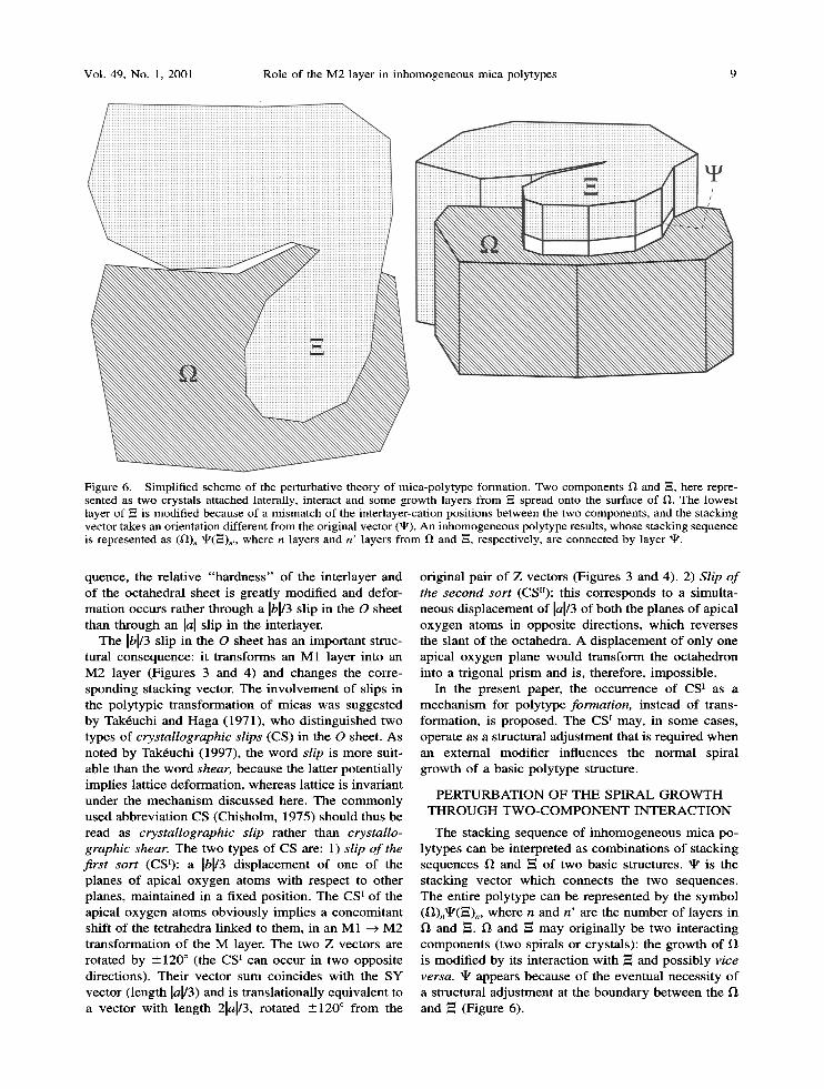
Figure 6. Simplified scheme of the perturbative theory of mica-polytype formation. Two components t) and --=, here repre- sented as two crystals attached laterally, interact and some growth layers from ~ spread onto the surface of O. The lowest layer of ,= is modified because of a mismatch of the interlayer-cation positions between the two components, and the stacking vector takes an orientation different from the original vector (~). An inhomogeneous polytype results, whose stacking sequence is represented as (O), ~(-=)~,, where n layers and n' layers from fl and -=, respectively, are connected by layer ~ .
quence , the re la t ive " h a r d n e s s " of the in ter layer and of the oc tahedra l shee t is great ly modif ied and defor- ma t ion occurs ra ther th rough a Ibl/3 slip in the O sheet than th rough an lal slip in the interlayer.
The Ibl/3 slip in the O sheet has an impor tan t struc- tural consequence : it t r ans forms an M1 layer into an M 2 layer (Figures 3 and 4) and changes the corre- spond ing s tacking vector. The i n v o l v e m e n t of slips in the polytypic t r ans fo rmat ion of micas was suggested by Tak6uchi and Haga (1971), who d i s t ingu ished two types of crystallographic slips (CS) in the O sheet. As no ted by Tak6uchi (1997), the word slip is more suit- able than the word shear, because the latter potent ia l ly impl ies latt ice deformat ion , whereas latt ice is invar ian t unde r the m e c h a n i s m d iscussed here. The c o m m o n l y used abbrev ia t ion CS (Chisho lm, 1975) should thus be read as crystallographic slip ra ther than crystallo- graphic shear. The two types of CS are: 1) slip of the first sort (CS~): a Ibl/3 d i sp lacemen t of one of the p lanes o f apical oxygen a toms wi th respect to o ther planes, ma in ta ined ira a fixed posi t ion. The CS t of the apical oxygen a toms obv ious ly impl ies a concomi t an t shif t of the te t rahedra l inked to them, in an M1 ~ M 2 t r ans fo rmat ion o f the M layer. The two Z vectors are ro ta ted by - 1 2 0 ~ ( the CS I can occur in two opposi te direct ions) . The i r vec tor sum coinc ides wi th the SY vector ( length lal/3) and is t rans la t ional ly equ iva len t to a vec tor wi th l eng th 2 H / 3 , ro ta ted ---120 ~ f rom the
or ig inal pa i r of Z vectors (Figures 3 and 4). 2) Slip o f the second sort (CSn): this cor responds to a s imulta- neous d i sp l acemen t of ]a]/3 of bo th the p lanes of apical oxygen a toms in opposi te direct ions, w h i c h reverses the s lant of the octahedra. A d i sp l acemen t o f on ly one apical oxygen p lane would t r ans fo rm the oc t ahedron into a t r igonal p r i sm and is, therefore , imposs ib le .
In the present paper, the occur rence of CS ~ as a m e c h a n i s m for po ly type formation, ins tead o f t rans- format ion , is proposed. The CS t may, in some cases, operate as a s tructural ad jus tmen t tha t is requi red w h e n an externa l modif ie r inf luences the no rma l spiral g rowth of a bas ic po ly type structure.
P E R T U R B A T I O N O F T H E S P I R A L G R O W T H T H R O U G H T W O - C O M P O N E N T I N T E R A C T I O N
The s tacking sequence of i n h o m o g e n e o u s mica po- ly types can be in terpre ted as combina t ions o f s tacking sequences f~ and -~ of two basic structures, q~ is the s tacking vec tor wh ich connec t s the two sequences . The ent i re po ly type can be represen ted b y the symbol ( ~ ) , ~ ( ~ ) n , where n and n ' are the n u m b e r of layers in 1~ and --=. ~ and ~ m a y or ig inal ly be two in terac t ing c o m p o n e n t s ( two spirals or crystals): the g rowth of is modif ied by its in terac t ion wi th ~ and poss ib ly vice versa. ~ appears because of the even tua l necess i ty of a structural ad jus tmen t at the b o u n d a r y b e t w een the l'l and ~ (Figure 6).
10 Nespolo Clays and Clay Minerals
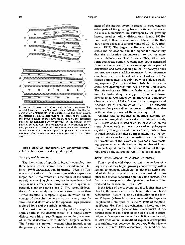
Figure 7. Recovery of the original stacking sequence of a crystal growing by spiral growth when disturbed by the de- position of a platelet (P) on the surface. (a) The spiral covers the platelet by elastic deformation; (b) some of the layers in the exposed ledge of the spiral are stopped by the deposited platelet; the remaining layers protrude on the surface of the platelet. In both cases, rearrangement of the protruding spiral may be necessary (shown by arrows) to match the interlayer- cation position. S: original spiral; P: platelet; S': spiral as modified after intersecting the platelet (courtesy of H. Take- da).
Three kinds of interactions are conceived: spiral- spiral, spiral-crystal, and crystal-crystal.
Spiral-spiral interaction
The interaction of spirals is broadly classified into three general cases (Verma, 1953; Lemmle in and Du- kova, 1956; Sunagawa and Bennema, 1982). 1) Two screw dislocations o f the same sign with a separation larger than 19r*/2, where r* is the radius o f the critical two-dimensional nucleus, produce independent spiral steps which, after a few turns, result in a system of parallel, nonintersecting steps. 2) Two screw disloca- tions o f the same sign with a separation smaller than 19r*/2 produce a composi te spiral in which an ex- change of the spiral centers occurs at every turn. 3) Two screw dislocations of the opposite sign produce a c losed loop and the spirals annihilate.
The most c o m m o n mechanism by which composi te spirals form is the decomposi t ion of a single screw dislocation with a large Burgers vector into a cluster of screw dislocations with shorter Burgers vectors. The former is commonly created when impurities on the growing surface act as obstacles and the advance-
ment of the growth layers is forced to stop, whereas other parts o f the growing fronts continue to advance. As a result, impurities are entrapped by the growing layers, creating hol low dislocations (Frank, 1951b). For micas, hol low dislocations are observed if the Bur- gers vector exceeds a critical value of 2 0 - 4 0 ,~ (Bar- onnet, 1972). The larger the Burgers vector, the less stable the dislocation, and the higher the probabili ty that the dislocation decomposes into two or more smaller dislocations close to each other, which can form composi te spirals. A composi te spiral generated f rom the interaction of two or more spirals in parallel orientation and corresponding to the 1M polytype does not produce a new stacking sequence. A new sequence can, however, be obtained when at least one of the spirals corresponds to a polytype with a zigzag stack- ing sequence (i.e., different f rom 1M). In this case, a spiral turn decomposes into two or more unit layers. The advancing rate differs with the advancing direc- tion: it is faster along the stagger direction and s lower normal to it. Consequently, interlacing is commonly observed (Frank, 1951a; Verma, 1953; Sunagawa and Koshino, 1975; Tomura et al., 1979). The different veloci ty along each direction creates a difference also in the relative position of the advancing front.
Another way to produce a modified stacking se- quence is through the interaction of twinned spirals, i.e., growth spirals rotated at angles o f n • 60 ~ on the same plateau, such as those observed on phlogopite crystals by Sunagawa and Tomura (1976). Where two twinned spirals, even those corresponding to a 1M po- lytype, interact to form a composi te spiral, the differ- ent orientation of the layers can produce a new stack- ing sequence, which depends on the number of layers f rom each spiral, on the relative orientation of the spi- rals, and on the advancing rate o f the spiral steps.
Spiral-crystal interaction. Platelet deposition
Thin crystal nuclei deposited onto the surface of a larger crystal may begin growing cooperat ively with a second component , which can be either an act ive spi- ral of the larger crystal on which it deposited, or an- other thin crystal deposited onto the same surface. The first case corresponds to the "platelet mechan i sm" in- troduced by Takeda and Ross (1995).
I f the ledge of the growing spiral is higher than the platelet, the former covers the latter either via elastic deformation (Figure 7a) or by substitution of the low- est N layers (where N is the number of the layers in the platelet) of the spiral with the N layers of the plate- let (Figure 7b). The first mechan ism is l ikely only for a very thin platelet (one or two layers thick). A de- posited platelet can occur in one of six stable orien- tations with respect to the surface. If it occurs in a (0, - 120 ~ orientation, the modified sequence corresponds to a subfamily-A polytype. In contrast, i f the platelet occurs in (_+60 ~ 180 ~ orientation, the modified se-
Vol. 49, No. 1, 2001 Role of the M2 layer in inhomogeneous mica polytypes 11
(a)
C*
! .......................... (b)
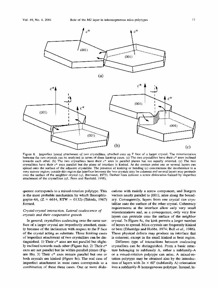
Figure 8. Imperfect lateral attachment of two crystallites, attached onto an F face of a larger crystal. The misorientation between the two crystals can be analyzed in terms of three limiting cases. (a) The two crystallites have their c* axes inclined towards each other. (b) The two crystallites have their c* axes in parallel planes but not equally oriented. (c) The two crystallites have their c* axes parallel but the plane of interface is kinked. At the contact point one or several layers can spread onto the surface of the adjacent crystallite. The presence of kinking or bending (c) concentrates the incoherence to a very narrow region; outside this region the interface between the two crystals may be coherent and several layers may protrude onto the surface of the neighbor crystal (cf., Baronnet, 1973). Dashed lines indicate a screw dislocation formed by imperfect attachment of the crystallites (cf., Penn and Banfield, 1998).
quence cor responds to a mixed- ro ta t ion polytype. This is the mos t p robab le m e c h a n i s m by wh ich f luorophlo- gopi te-4A 5 (Z = 6614, R T W = 0132) (Takeda, 1967) formed.
Crystal-crystal interaction. Lateral coalescence of crystals and their cooperative growth
In general , crysta l l i tes coalesc ing on to the same sur- face of a larger crys ta l are imper fec t ly a t tached, ma in - ly because of the inc l ina t ion wi th respect to the F face o f the crysta l act ing as substrate. Three l imi t ing cases o f imper fec t a t t a chmen t of two crys ta l l i tes can be dis- t inguished. 1) The i r c* axes are no t paral le l bu t s l ight- ly inc l ined towards each other (Figure 8a). 2) The i r c* axes are not paral lel bu t lie wi th in paral lel p lanes (Fig- ure 8b). 3) The i r c* axes r ema in paral lel bu t one or bo th crys ta ls are k inked (Figure 8c). The real case of imper fec t a t t achmen t in mos t cases cor responds to a comb ina t i on of these three cases. One or more dislo-
cat ions wi th ma in ly a screw componen t , and Burgers vectors near ly paral le l to [001 ], arise a long the bound- ary. Consequent ly , layers f rom one crys ta l can crys- tal l ize onto the surface of the o ther crystal . C o h e r e n c y requ i rement s at the in te r face al low only ve ry smal l misor ien ta t ions and, as a consequence , only ve ry few layers can prot rude onto the surface o f the n e i g h b o r crystal . In F igure 8c, the k ink permi ts a larger n u m b e r o f layers to spread. M i c a crys ta ls are f requent ly k inked or ben t (Ether idge and Hobbs , 1974; Bel l et aL, 1986). These phys ica l defects m a y produce an in te r face that is coherent , except in the smal l k inked or ben t region.
Dif ferent type o f in terac t ions b e t w e e n coa lesc ing crysta l l i tes can be d is t inguished. F r o m a basic struc- ture be long ing to subfami ly A, e i ther a sub fami ly -A or a mixed- ro ta t ion po ly type can arise. A mixed- ro - ta t ion po ly type m a y be ob ta ined also by the in t roduc- t ion of layers wi th 2n • 60 ~ ( subfami ly A) or ien ta t ion into a subfarni ly-B h o m o g e n e o u s polytype. Ins tead ,qn-
12 Nespolo Clays and Clay Minerals
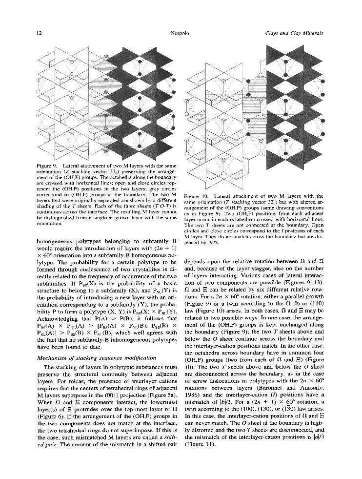
Figure 9. Lateral attachment of two M layers with the same orientation (Z stacking vector 330) preserving the arrange- ment of the (OH,F) groups. The octahedra along the boundary are crossed with horizontal lines; open and close circles rep- resent the (OH,F) positions in the two layers; gray circles correspond to (OH,F) groups at the boundary. The two M layers that were originally separated are shown by a different shading of the T sheets. Each of the three sheets (T-O-T) is continuous across the interface. The resulting M layer cannot be distinguished from a single as-grown layer with the same orientation.
h o m o g e n e o u s poly types be long ing to subfami ly B would requi re the in t roduct ion of layers wi th (2n + l ) x 60 ~ or ien ta t ion into a subfami ly -B h o m o g e n e o u s po- lytype. The probabi l i ty for a cer ta in po ly type to be fo rmed th rough coa lescence of two crysta l l i tes is di- rect ly re la ted to the f requency of occur rence of the two subfamil ies . I f PBs(X) is the probabi l i ty o f a bas ic s t ructure to be long to a subfami ly (X), and PNL(Y) is the probabi l i ty of in t roduc ing a new layer wi th an ori- en ta t ion co r respond ing to a subfami ly (Y), the proba- bi l i ty P to fo rm a po ly type (X, Y) is Pss(X) x PNL(Y). A c k n o w l e d g i n g that P(A) > P(B) , it fo l lows that PBs(A) • PNL(A) ~ [Pas(A) X PNL(B), PBs(B) X PNL(A)] > PBs(B) X PNL(B), wh ich wel l agrees wi th the fact that no subfami ly -B i n h o m o g e n e o u s poly types have b e e n found to date.
Mechanism o f stacking sequence modification
The s tacking o f layers in polytypic subs tances mus t p rese rve the s t ructural cont inui ty be tween ad jacent layers. For micas , the p resence of in ter layer cat ions requires tha t the centers of te t rahedra l r ings of ad jacent M layers superpose in the (001) pro jec t ion (Figure 5a). W h e n f~ and ~ c o m p o n e n t s interact , the lowermos t layer(s) of ,~ prot rudes over the top-mos t layer of f~ (Figure 6). I f the a r r angemen t of the (OH,F) groups in the two c o m p o n e n t s does not ma tch at the interface, the two te t rahedra l r ings do not super impose . If this is the case, such m i s m a t c h e d M layers are ca l led a shift- ed pair. The a m o u n t of the m i s m a t c h in a shi f ted pair
Figure 10. Lateral attachment of two M layers with the same orientation (Z stacking vector 330) but with altered ar- rangement of the (OH,F) groups (same drawing conventions as in Figure 9). Two (OH,F) positions from each adjacent layer occur in each octahedron crossed with horizontal lines. The two T sheets are not connected at the boundary. Open circles and close circles correspond to the I positions of each M layer. They do not match across the boundary but are dis- placed by Ibl/3.
depends upon the relat ive rota t ion b e t w een f~ and and, because of the layer stagger, also on the n u m b e r of layers interact ing. Various cases of lateral interac- t ion of two c o m p o n e n t s are poss ib le (Figures 9 - 1 3 ) .
and ~ can be related by six di f ferent re la t ive rota- t ions. For a 2n • 60 ~ rotat ion, e i ther a paral lel growth (Figure 9) or a twin accord ing to the (110) or (1]-0) law (Figure 10) arises. In bo th cases, 12 and E m a y be re la ted in two poss ible ways. In one case, the ar range- men t of the (OH,F) groups is kep t u n c h a n g e d a long the b o u n d a r y (Figure 9); the two T sheets above and be low the O sheet cont inue across the b o u n d a r y and the in ter layer-cat ion posi t ions match. In the o ther case, the oc tahedra across b o u n d a r y have in c o m m o n four (OH,F) groups ( two f rom each of f~ and ~,) (Figure 10). The two T sheets above and be low the O sheet are d i sconnec ted across the boundary , as in the case of screw dis locat ions in poly types wi th the 2n X 60 ~ ro ta t ions be tween layers (Baronne t and Amour ic , 1986) and the in ter layer-cat ion (/) pos i t ions have a m i s m a t c h of ]b]/3. For a (2n + 1) X 60 ~ rotat ion, a twin accord ing to the (100), (130), or (150) law arises. In this case, the in ter layer-cat ion posi t ions of g~ and can neve r match. The O sheet at the b o u n d a r y is h igh- ly dis tor ted and the two T sheets are d isconnected , and the m i s m a t c h of the in ter layer-cat ion posi t ions is 14/3 (Figure 11).
Vol. 49, No. 1, 2001 Role of the M2 layer in inhomogeneous mica polytypes 13
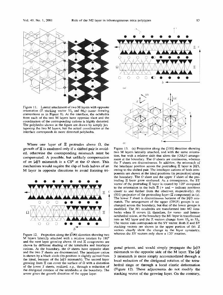
Figure l 1. Lateral at tachment o f two M layers with opposite orientation (Z stacking vector 330 and 660) (same drawing convent ions as in Figure 9). At the interface, the octahedra f rom each of the two M layers have opposite slant and the coordination o f the corresponding cations is highly distorted. The polyhedra shown in the figure are drawn by simply jux- taposing the two M layers, but the actual coordination at the interface corresponds to more distorted polyhedra.
W h e r e o n e l a y e r o f -= p r o t r u d e s a b o v e 12, t he
g r o w t h o f --= is u n a l t e r e d o n l y i f a s h i f t e d pa i r is a v o i d -
ed , o t h e r w i s e t he c o r r e s p o n d i n g m i s m a t c h m u s t b e c o m p e n s a t e d . A p o s s i b l e , b u t u n l i k e l y c o m p e n s a t i o n
o f a n lal/3 m i s m a t c h is a C S n a t t h e O shee t . T h i s
m e c h a n i s m w o u l d r e q u i r e t h e s l ip o f b o t h h a l v e s o f a n
M l a y e r in o p p o s i t e d i r e c t i o n s to a v o i d f o r m i n g tri-
Figure 12. Projection along the [TO0] direction showing two M layers laterally attached with a relative rotation by 180 ~ and the next layer growing above. II and N components are shown by different shading of the tetrahedra and interlayer cations. At the boundary, the O sheets have opposite slant and the two T sheets are disconnected. The interlayer cation is shown by a black circle (its posit ion is slightly moved from the ideal, because of the lal/3 mismatch). The second layer growing from E can cover the surface o f 12 with a distortion of the lower T sheets, realized, e.g., through a reduction of the ditrigonal rotation of the tetrahedra at the boundary. The arrow gives the growth direction of the upper layer.
Figure 13. (a) Projection along the [1-00] direction showing two M layers laterally attached, and with the same orienta- tion, but with a relative shift that alters the (OH,F) arrange- ment at the boundary. The O sheets are continuous, whereas the T sheets are discontinuous. In addition, the mismatch o f the interlayer position across the protruding ,~ layer is ]bl13, owing to the shifted pair. The interlayer cations of both com- ponents are shown at the ideal positions (in projection) along the boundary. The O sheet and the upper T sheet of the pro- truding _= layer grow unaltered. As a consequence, the SY vector of the protruding --= layer is rotated by 120 ~ compared to the orientation in the bulk -= (+ and - indicate positions closer to and farther f rom the observer, respectively). (b) (001) projection of the protruding layer (-~ component) in (a). The lower T sheet is discontinuous because of the Ibl/3 mis- match. The arrangement of the upper (OH,F) groups is un- changed across the boundary, but that of the lower groups is modified. The M1 octahedra are t ransformed into M2 octa- hedra when E covers I~; therefore, for meso- and hetero- octahedral micas, at the boundary the M1 layer is t ransformed into an M2 layer and the Z vectors change from 330 to 530. The vector sum corresponds to the SY vector. Both Z and SY stacking vectors are shown in the upper portion of (b). Z vectors clearly show the change in the layer symmetry , whereas the SY vectors only show a 120 ~ rotation.
g o n a l p r i s m s , a n d w o u l d s i m p l y p r o p a g a t e t he H/3 m i s m a t c h to t he o p p o s i t e s ide o f t he M layer . T h e lal/ 3 m i s m a t c h is m o r e s i m p l y a c c o m m o d a t e d t h r o u g h a
loca l r e d u c t i o n o f t he d i t r i g o n a l r o t a t i o n o f t h e t e t ra -
h e d r a l r i n g s o r t h r o u g h a loca l e l a s t i c d e f o r m a t i o n
( F i g u r e 12). T h e s e a d j u s t m e n t s do n o t m o d i f y t h e s t a c k i n g v e c t o r o f t h e g r o w i n g layer . O n t h e c o n t r a r y ,
14 Nespolo Clays and Clay Minerals
L ' " ";V~" " '~ . ' " " - - .Z ' ' ' ' ; . . [31~] ~a, a3t[3~0]
-..- "-- - ">- " " " ~ " a
. . . . . . . . . . . . . 1 1 . . .
. " . . . : . ' ; " - . . / " - . " D'- .",. . . - " . . - p . I',." " - - " " -" "" 11 - .
. : . . . - _T ~.r .< "~ . "~2 ">21 "-'L . < . - . r - .
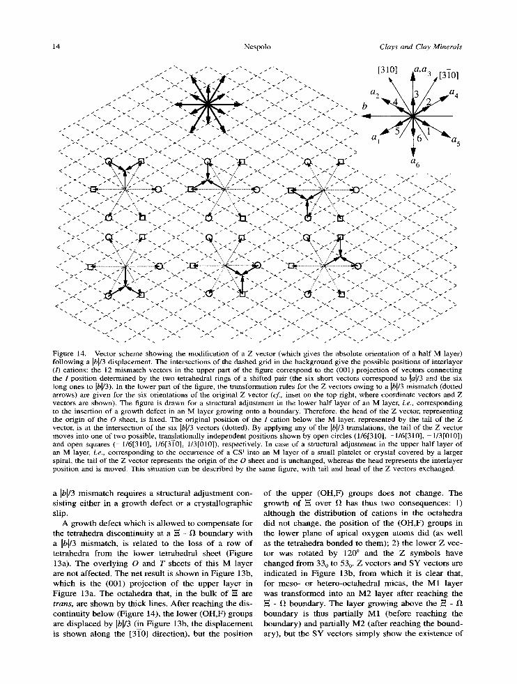
Figure 14. Vector scheme showing the modification of a Z vector (which gives the absolute orientation of a half M layer) following a H/3 displacement. The intersections of the dashed grid in the background give the possible positions of interlayer (/) cations: the 12 mismatch vectors in the upper part of the figure correspond to the (001) projection of vectors connecting the 1 position determined by the two tetrahedral rings of a shifted pair (the six short vectors correspond to [a[/3 and the six long ones to Ibl/3). In the lower part of the figure, the transformation rules for the Z vectors owing to a Ib[/3 mismatch (dotted arrows) are given for the six orientations of the original Z vector (cf., inset on the top-right, where coordinate vectors and Z vectors are shown). The figure is drawn for a structural adjustment in the lower half layer of an M layer, i.e., corresponding to the insertion of a growth defect in an M layer growing onto a boundary. Therefore, the head of the Z vector, representing the origin of the O sheet, is fixed. The original position of the I cation below the M layer, represented by the tail of the Z vector, is at the intersection of the six Ibl/3 vectors (dotted). By applying any of the [bl/3 translations, the tail of the Z vector moves into one of two possible, translationally independent positions shown by open circles (1/61310], -1/61310], -1/31010]) and open squares (-1/61310], 1/61310], 1/3[010]), respectively. In case of a structural adjustment in the upper half layer of an M layer, i.e., corresponding to the occurrence of a CS ~ into an M layer of a small platelet or crystal covered by a larger spiral, the tail of the Z vector represents the origin of the O sheet and is unchanged, whereas the head represents the interlayer position and is moved. This situation can be described by the same figure, with tail and head of the Z vectors exchanged.
a H / 3 mismatch requires a structural adjustment con- sisting either in a growth defect or a crystal lographic slip.
A growth defect which is a l lowed to compensa te for the tetrahedra discont inui ty at a ~ - ~ boundary with a IbV3 mismatch , is related to the loss of a row of tetrahedra f rom the lower tetrahedral sheet (Figure 13a). The overlying O and T sheets o f this M layer are not affected. The net result is shown in Figure 13b, which is the (001) project ion of the upper layer in Figure 13a. The octahedra that, in the bulk of E are t rans, are shown by thick lines. Af ter reaching the dis- continuity be low (Figure 14), the lower (OH,F) groups are d isplaced by Ibl/3 (in Figure 13b, the d isp lacement is shown along the [310] direction), but the posi t ion
of the upper (OH,F) groups does not change. The growth of ~ over 12 has thus two consequences : 1) al though the distribution of cat ions in the octahedra did not change, the posi t ion of the (OH,F) groups in the lower plane of apical oxygen atoms did (as well as the tetrahedra bonded to them); 2) the lower Z vec- tor was rotated by 120 ~ and the Z symbols have changed f rom 330 to 530. Z vectors and SY vectors are indicated in Figure 13b, f rom which it is clear that, for meso- or hetero-octahedral micas, the M1 layer was t ransformed into an M2 layer after reaching the ~= - ~ boundary. The layer growing above the E - 1~ boundary is thus partially M1 (before reaching the boundary) and partially M2 (after reaching the bound- ary), but the SY vectors s imply show the exis tence o f
Vol. 49, No. 1, 2001 Role of the M2 layer in inhomogeneous mica polytypes 15
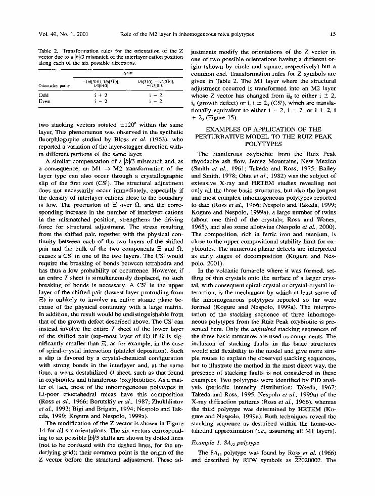
Table 2. Transformation rules for the orientation of the Z vector due to a Ibl/3 mismatch of the interlayer cation position along each of the six possible directions.
Shift
- 1/61310], 1/613T0], 1/61310], - 1/613T0], Or ien ta t ion par i ty l / 3 [010] - l /3 [010]
Odd i + 2 i - 2 Even i - 2 i + 2
two stacking vectors rotated _+120 ~ within the same layer, This phenomenon was observed in the synthetic fluorphlogopite studied by Bloss et al. (1963), who reported a variation of the layer-stagger direction with- in different portions of the same layer.
A similar compensation of a ]b[/3 mismatch and, as a consequence, an M1 --~ M2 transformation of the layer type can also occur through a crystallographic slip of the first sort (CSI). The structural adjustment does not necessarily occur immediately, especially if the density of interlayer cations close to the boundary is low. The protrusion of ~ over I~, and the corre- sponding increase in the number of interlayer cations in the mismatched position, strengthens the driving force for structural adjustment. The stress resulting from the shifted pair, together with the physical con- tinuity between each of the two layers of the shifted pair and the bulk of the two components ~ and ~, causes a CS ~ in one of the two layers. The CS ~ would require the breaking of bonds between tetrahedra and has thus a low probability of occurrence. However, if an entire T sheet is simultaneously displaced, no such breaking of bonds is necessary. A CS I in the upper layer of the shifted pair (lowest layer protruding from --=) is unlikely to involve an entire atomic plane be- cause of the physical continuity with a large matrix. In addition, the result would be undistinguishable from that of the growth defect described above. The CS I can instead involve the entire T sheet of the lower layer of the shifted pair (top-most layer of 1~) if 1) is sig- nificantly smaller than ~, as for example, in the case of spiral-crystal interaction (platelet deposition). Such a slip is favored by a crystal-chemical configuration with strong bonds in the interlayer and, at the same time, a weak destabilized O sheet, such as that found in oxybiotites and titanlferous (oxy)biotities. As a mat- ter of fact, most of the inhomogeneous polytypes in Li-poor trioctahedral micas have this composition (Ross et aL, 1966; Borutskiy et al., 1987; Zhukhlistov et al., 1993; Bigi and Brigatti, 1994; Nespolo and Tak- eda, 1999; Kogure and Nespolo, 1999a).
The modification of the Z vector is shown in Figure 14 for all six orientations. The six vectors correspond- ing to six possible Ibm3 shifts are shown by dotted lines (not to be confused with the dashed lines, for the un- derlying grid); their common point is the origin of the Z vector before the structural adjustment. These ad-
justments modify the orientations of the Z vector in one of two possible orientations having a different or- igin (shown by circle and square, respectively) but a common end. Transformation rules for Z symbols are given in Table 2. The M1 layer where the structural adjustment occurred is transformed into an M2 layer whose Z vector has changed from ii0 to either i - 2, io (growth defect) or i, i -+ 2o (CSX), which are transla- tionally equivalent to either i - 2, i - 20 or i + 2, i + 20 (Figure 15).
EXAMPLES OF APPLICATION OF THE PERTURBATIVE MODEL TO THE RUIZ PEAK
POLYTYPES
The titaniferous oxybiotite from the Ruiz Peak rhyodacite ash flow, Jemez Mountains, New Mexico (Smith et al., 1961; Takeda and Ross, 1975; Bailey and Smith, 1978; Ohta et al., 1982) was the subject of extensive X-ray and HRTEM studies revealing not only all the three basic structures, but also the longest and most complex inhomogeneous polytypes reported to date (Ross et al., 1966; Nespolo and Takeda, 1999; Kogure and Nespolo, 1999a), a large number of twins (about one third of the crystals; Ross and Wones, 1965), and also some allotwins (Nespolo et al., 2000). The composition, rich in ferric iron and titanium, is close to the upper compositional stability limit for ox- ybiotites. The numerous planar defects are interpreted as early stages of decomposition (Kogure and Nes- polo, 2001).
In the volcanic fumarole where it was formed, set- fling of thin crystals onto the surface of a larger crys- tal, with consequent spiral-crystal or crystal-crystal in- teraction, is the mechanism by which at least some of the inhomogeneous polytypes reported so far were formed (Kogure and Nespolo, 1999a). The interpre- tation of the stacking sequence of three inhomoge- neous polytypes from the Ruiz Peak oxybiotite is pre- sented here. Only the unfaul ted stacking sequences of the three basic structures are used as components. The inclusion of stacking faults in the basic structures would add flexibility to the model and give more sim- ple routes to explain the observed stacking sequences, but to illustrate the method in the most direct way, the presence of stacking faults is not considered in these examples. Two polytypes were identified by PID anal- ysis (periodic intensity distribution: Takeda, 1967; Takeda and Ross, 1995; Nespolo et al., 1999a) of the X-ray diffraction patterns (Ross et al., 1966), whereas the third polytype was determined by HRTEM (Ko- gure and Nespolo, 1999a). Both techniques reveal the stacking sequence as described within the homo-oc- tahedral approximation (i.e., assuming all M1 layers).
E x a m p l e 1. 8A12 po ly t ype
The 8A12 polytype was found by Ross et al. (1966) and described by RTW symbols as 22020002. The
16 Nespolo Clays and Clay Minerals
330~-"130 + 550
~~176176
330---'530 + 110
440
550 ~350 + 110
550-- ~ 150 + 330
i -- 240 + 660
r
t
440---*640 + 220
660---460 + 220
' . . . . .~oo I ~ ~
110--"510 + 33 0 r
I I
r 0
. . . . e
110---310 + 550
a 2
~ ,a 3
3/a4
~ a 5
t/.
440----640 + 22 0 220---'420 + 660
660 ~260 +44 0 . ' f ~ .
. .... < t Figure 15. Transformation rules for an M1 --~ M2 layer transformation obtained through a ]b[/3 shift of the lower half-layer (structural adjustment through insertion of a growth defect). Solid thin vector pairs are pairs of Z vectors before structural adjustment, Dotted thin lines are directions of the shift. Dotted thin vectors are lower Z vectors after structural adjustment, Solid thick vectors are SY vectors. Dotted thick vectors are pairs of Z vectors as they appear in the homo-octahedral approximation (translationally equivalent to SY vectors). The symbol "ii0 ~ ji0 + kk0" stands for "layer with orientation ii 0 transforms to ji0, which, in the homo-octahedral approximation, is equivalent to kk0". A similar figure can be drawn for the case of a structural adjustment obtained through a CS ~, altering the second Z vector (upper half of the M layer) instead of the first one. Inset on the right upper corner: Z vectors and coordinate axes.
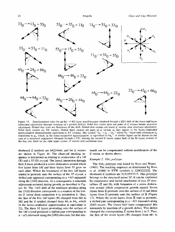
shor tened Z symbols are 64224444, and the Z vectors are shown in Figure 16. The obse rved stacking se- quence is interpreted as relat ing to coalescence of a 1M (~ ) and a 3T (~ ) crystal. The lateral interact ion through their S faces produced a screw dislocat ion around which five layers f rom I M and three layers f rom 3T grew on each other. W h e r e the lowermost of the five 1M layers started to protrude onto the surface of the 3T crystal, a shifted pair appeared corresponding to a +b/3 mismatch a long the [310] direction. As a consequence, a structural ad jus tment occurred dur ing growth, as descr ibed in Fig- ure 10. The +hi3 shift of the inter layer posi t ion along the [310] direct ion corresponds to a rotat ion of the low- est Z vector f rom orientat ion 4 to or ientat ion 6. Thus, the first of the five 1M layers (xlt) changed f rom M1 to M 2 and the Z symbol changed f rom 44 o to 640, which in the homo-octahedra l approximat ion is equivalent to 22o. The three 3T layers protruding onto the surface of the 1M crystal p roduced a shif ted pair corresponding to a - a / 3 misma tch along the [100] direction, but this mis-
match can be compensa ted wi thout modif icat ion of the Z vector, as shown above.
Example 2. IOA 3 po ly type
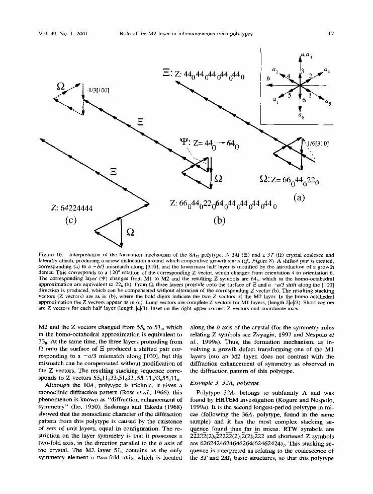
The 10A3 poly type was found by Ross and Wones (1965). The s tacking sequence as de t e rmined b_y Ross et al. (1966) in R T W symbols is 2200222222. The shor tened Z symbols are 51333513513 . This po ly type be longs to the structural series 3T. It can be exp la ined by coa lescence and lateral a t t achment of two 3T crys- tall i tes ( ~ and fl) , wi th fo rmat ion of a screw disloca- t ion around wh ich coopera t ive g rowth started. Seven layers f rom ,= pro t rude onto the surface of ~ and three layers f rom ~ prot rude on to the surface of ~ (Figure 17). W h e r e the seven layers f rom --~ start to protrude, a shi f ted pair cor responding to a - b / 3 m i s m a t c h a long [010] occurs. The lowes t ha l f layer compensa t ed this m i s m a t c h by inser t ion of a g rowth defect. This defect changed the co r respond ing Z vec tor f rom 1 to 5. Thus , the first of the seven layers ( ~ ) changed f rom M1 to
Vol. 49, No. 1, 2001 Role of the M2 layer in inhomogeneous mica polytypes 17
a,a 3
- ~ a 2 @ a 4 ~" Z: 44044 044 044 044 0 b
a, o5
a66~ ~ ~ ~I/: Z= 44d---" I310J
~-2 ~'2: Z= 660440220 (a)
Z: 6~2)4444 Z: 66044022064044 044044044 0 (b)
Figure 16. Interpretation of the formation mechanism of the 8A~z polytype. A 1M (N) and a 3?" (ll) crystal coalesce and laterally attach, producing a screw dislocation around which cooperative growth starts (cf, Figure 8). A shifted pair is created, corresponding (a) to a +b/3 mismatch along [310], and the lowermost half layer is modified by the introduction of a growth defect. This corresponds to a 120 ~ rotation of the corresponding Z vector, which changes from orientation 4 to orientation 6. The corresponding layer (~P) changes from M1 to M2 and the resulting Z symbols are 640, which in the homo-octahedral approximation are equivalent to 22o (b). From II, three layers protrude onto the surface of ~ and a -a/3 shift along the [100] direction is produced, which can be compensated without alteration of the corresponding Z vector (b). The resulting stacking vectors (Z vectors) are as in (b), where the bold digits indicate the two Z vectors of the M2 layer. In the homo-octahedral approximation the Z vectors appear as in (c). Long vectors are complete Z vectors for M 1 layers, (length 2[a1/3). Short vectors are Z vectors for each half layer (length lal/3). Inset on the right upper comer: Z vectors and coordinate axes.
M 2 and the Z vectors c h a n g e d f rom 55o to 51 o, wh ich in the homo-oc tahed ra l approx imat ion is equ iva len t to 33o. At the same t ime, the three layers pro t ruding f rom 1) onto the surface of ~ p roduced a shif ted pair cor- r e spond ing to a - a / 3 m i s m a t c h a long [100], but this m i s m a t c h can be c o m p e n s a t e d wi thou t modif ica t ion o f the Z vectors. The resul t ing s tacking sequence corre- sponds to Z vectors 55011o33051033 o 55011o33o550110.
A l though the 10A3 po ly type is triclinic, it g ives a monoc l in ic di f f ract ion pat tern (Ross et al., 1966): this p h e n o m e n o n is k n o w n as "d i f f rac t ion e n h a n c e m e n t of s y m m e t r y " (Ito, 1950). Sadanaga and Takeda (1968) showed that the monoc l in i c charac te r o f the di f f ract ion pat tern f rom this po ly type is caused by the ex is tence of sets of uni t layers, equal in configurat ion. The re- st 'fiction on the layer s y m m e t r y is that i t possesses a two- fo ld axis, in the d i rec t ion paral lel to the b axis of the crystal . The M 2 layer 51o conta ins as the only s y m m e t r y e l emen t a two-fo ld axis, wh ich is located
a long the b axis o f the crys ta l ( for the s y m m e t r y rules re la t ing Z symbols see Zvyag in , 1997 and Nespo lo et al., 1999a). Thus , the fo rmat ion m e c h a n i s m , as in- vo lv ing a g rowth defect t r ans fo rming one of the M1 layers in to an M 2 layer, does not cont ras t wi th the diff ract ion e n h a n c e m e n t of s y m m e t r y as o b s e r v e d in the di f f ract ion pat tern of this polytype.
Example 3. 32A~ polytype
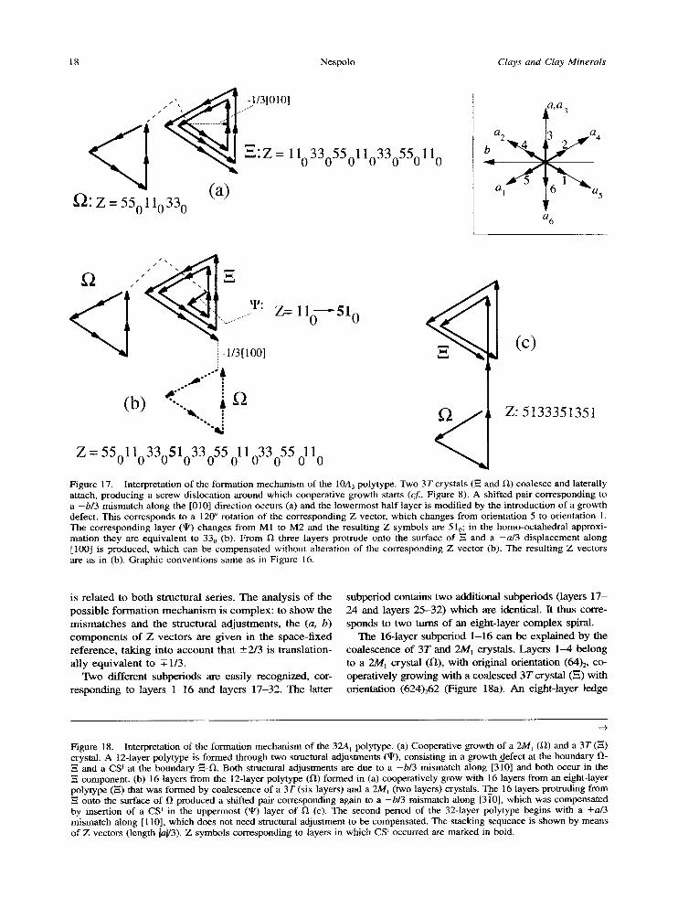
Poly type 32Aj be longs to subfami ly A and was found by H R T E M inves t iga t ion (Kogure and Nespolo , 1999a). It is the second longes t -per iod po ly type in mi- cas ( fo l lowing the 36A1 polytype, found in the same sample) and it has the mos t comp lex s tacking se- quence found thus far in micas . R T W symbol s are 22222(2)522222(2)62(2)7222 and shor tened Z symbols are 6262424624646264(62462424)2 . Th i s s tacking se- quence is in terpre ted as re la t ing to the coa lescence o f the 3T and 2M~ basic structures, so that this po ly type
18 Nespolo Clays and Clay Minerals
;1/3[010l / ..J"
, ' . :Z = 110330550110330550110
(a) ~2: z = 550110330
a 2
~ a 1 ~ 5
a,a 3
a4
6 a 5
06
f2 E
< I ~ uL: Z = 1 1 0 - - ~ 5 1 0 i - 1 / 3 [ 1 0 0 ] ...................... ~ ( C )
.~176 ...... A
(b)
Z - 55011033051033055 011033055 0110
Z:5t33351351
Figure 17. Interpretation of the formation mechanism of the 10A3 polytype. Two 3Tcrystals (--= and 1~) coalesce and laterally attach, producing a screw dislocation around which cooperative growth starts (cf., Figure 8). A shifted pair corresponding to a -b /3 mismatch along the [010] direction occurs (a) and the lowermost half layer is modified by the introduction of a growth defect. This corresponds to a 120 ~ rotation of the corresponding Z vector, which changes from orientation 5 to orientation 1. The corresponding layer (~) changes from M1 to M2 and the resulting Z symbols are 510; in the homo-octahedral approxi- mation they are equivalent to 330 (b). From 1) three layers protrude onto the surface of E and a -a /3 displacement along [100] is produced, which can be compensated without alteration of the corresponding Z vector (b). The resulting Z vectors are as in (b). Graphic conventions same as in Figure 16.
is related to both structural series. The analysis of the possible formation mechanism is complex: to show the mismatches and the structural adjustments, the (a, b) components of Z vectors are g iven in the space-fixed reference, taking into account that _+2/3 is translation- ally equivalent to ~-1/3.
Two different subperiods are easily recognized, cor- responding to layers 1-16 and layers 17-32. The latter
subperiod contains two additional subperiods (layers 17- 24 and layers 25-32) which are identical. It thus corre- sponds to two turns of an eight-layer complex spiral.
The 16-layer subperiod 1-16 can be explained by the coalescence of 3T and 2M1 crystals. Layers 1-4 belong to a 2M I crystal (1~), with original orientation (64) 2, co- operatively growing with a coalesced 3T crystal (~.) with orientation (624)262 (Figure 18a). An eight-layer ledge
-q,
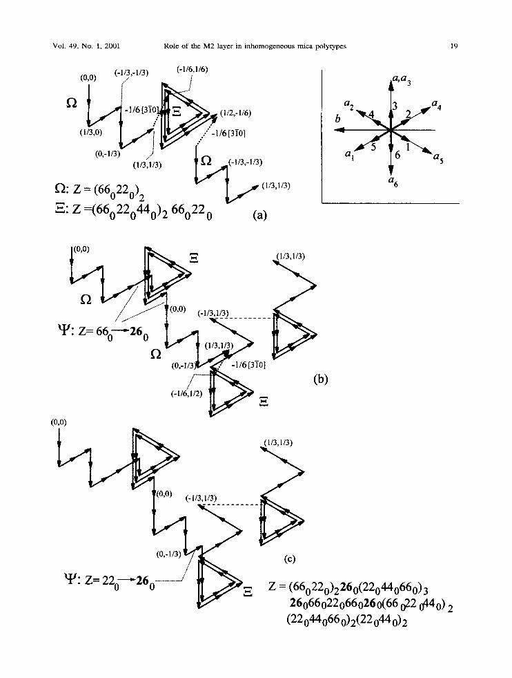
Figure 18. Interpretation of the formation mechanism of the 32A t polytype. (a) Cooperative growth of a 2MI (ll) and a 3T (-=) crystal. A 12-layer polytype is formed through two sauctural adjustments (qt), consisting in a growth_defect at the boundary l)-
and a CS ~ at the boundary ~-12. Both structural adjustments are due to a -b /3 mismatch along [310] and both occur in the component. (b) 16 layers from the 12-layer polytype (fl) formed in (a) cooperatively grow with 16 layers from an eight-layer
polytype (,=) that was formed by coalescence of a 3T (six layers) and a 2M~ (two layers) crystals. The 16 layers protruding from onto the surface of 1~ produced a shifted pair corresponding again to a -b /3 mismatch along [310], which was compensated
by insertion of a CS 1 in the uppermost (~) layer of ~ (c). The second period of the 32-layer polytype begins with a +a/3 mismatch along [110], which does not need structural adjustment to be compensated. The stacking sequence is shown by means of Z vectors (length la[/3). Z symbols corresponding to layers in which CS ~ occurred are marked in bold.
Vol. 49, No. 1, 2001 Role of the M2 layer in inhomogeneous mica polytypes 19
(0,0) (-1/3,-1/3) (-1/6,1/6) i
/ - 1 / 6 [ 3 i 0 . ~ ~ . (1/2,-1/6)
(1/3,0, . ~ 1 ~ / . 1 / 6 t 3 i 0 ]
(0,1/3): J ~ / "" (1/3('i/3) ~(-1/3 , -1 /3)
~: Z = (660220) 2 - ~ (1/3,1/3,
~: Z =(660220440) 2 66022 0 (a)
a 6
~ ~ ~(oo, (31 z66o
(-1/6,1/2) ~
(o,o)
(b)
~ (1/3,1/3)
~IJ: Z= 220--'260 ............. / ~ ~ ~ , Z= (660220)2260(220440660) 3 260660220660260(66 022 0440 ) 2
(22044066 0)2(22 044 O) 2
20 Nespolo Clays and Clay Minerals
protruded from ~ onto the surface of l~. Assuming the origin of the four-layer ledge of ~ in correspondence of coordinates (0, 0), its fourth Z vector ends with coordi- nates (1/3, 1/3) (Figure 18a). ff the origin of the eight- layer ~ ledge was at ( -1 /6 , 1/6) where it protruded on crystal ~ , the ledge produced a shifted pair with a - b / 3 mismatch along the [31-0] direction. The structural ad- jus tment ( 4 ) is seen in the first layer of --=. Therefore, this adjustment corresponds to a growth defect. The stacking sequence o f ~ , expressed by complete Z sym- bols, changes f rom 66o22o44o66o22o44o66o22o to 26022o44o66o22044066022o; Z = 260 is translationally equivalent to Z = 44 o (Figure 18a). The uppermost layer of ~ ends with coordinates (1/2, - 1 / 6 ) . Four layers f rom ~ protrude onto the surface o f E. The first layer o f ~ has coordinates (0, 0), leading again to a mismatch o f - b / 3 , along [510] direction. This time, the structural adjustment is seen in the uppermost layer ( 4 ) of ~ , which undergoes a CS% changing its orien- tation f rom Z = 22 o to Z = 26o (Figure 18b). This kind of structural adjustment indicates that an entire plane slipped, and that a significant difference in size be tween the two crystals exists (f~ >> ~) . By means of two structural adjustments (one growth defect and one CS I, both in ~ ) a perfect match of the interlayer- cation positions was achieved and, f rom this point, a 12-layer polytype begins to grow. The Z symbols are 66o220660220260220440660220440660260 , which are equiv- alent to 626242462464 in the homo-octahedral approx- imation.
Growth of the 12-layer polytype was then modif ied by cooperat ive growth with another crystal. This sec- ond crystal (layers 17-32) was an eight-layer polytype formed by interaction of six layers f rom a 3T crystal and two layers f rom a 2Mj crystal. Two periods (16 layers) of this polytype (~) protruded onto the surface o f the 12-layer polytype (l~), f rom which a 16-layer sequence protruded onto the surface of ~ . Fixing the coordinates of the origin of the first layer as (0, 0), the ledge ends at (1/3, 1/3). If the origin of ~ is at ( - 1/6, 1/2), then a mismatch of - b / 3 occurs, along the [3]0] direction (Figure 18b). The structural adjustment oc- curs as a CS I in the uppermost layer (4 ) of f~, and this is in favor of a significant difference in size be- tween the two crystals (E >> l~). The corresponding Z vector changes f rom 220 to 260, translationally equiv- alent to 440. The uppermost layer of ~ (which is also the uppermost layer of the 32-layer polytype) ends with coordinates (1/3, 1/3) and a +a/3 mismatch along [110] arises with respect to the lowermost layer of l-l, i.e., the first layer of the second repeat of the 32-layer polytype, with coordinates (0, 0). As seen above, this mismatch is compensated without need of a structural adjustment. Comple te Z symbols are g iven in Figure 18c, where the vectors of the layers in which CS r oc- curred are marked by bold characters.
D I S C U S S I O N
Growth defects and CS I modify the location of the M1 site and can be described as + 1 2 0 ~ rotations of the SY vector. Al though this effect is unimportant for homo-octahedral micas, in meso- and hetero-octahe- dral micas it transforms an M 1 layer into an M2 layer. M2 layers were found both in trioctahedral and in dioctahedral micas, but the coexis tence of M1 and M2 layers in an inhomogeneous polytype has not been proved as yet. The occupation of the cationic sites in the O sheet is modified, but this change may be dif- ficult to extract f rom a structure refinement. Because of the physical deformation and bending of the crys- tals, the quality of a diffraction pattern f rom mica is often poor, with oval-shaped, broad, and streaked re- flections. The poor quality of diffraction is a severe obstacle to structure refinement. To date, the only structure refinement of an inhomogeneous polytype (3M2) was performed by Rule et al. (1987), with a final R factor of 12%. The quality of the refinement is clearly insufficient to distinguish the possible presence of an M2 layer (furthermore, this is a mixed-rotat ion polytype, in which the (2n + 1) • 60 ~ rotation does not involve an M1 --+ M2 layer transformation, as in the case of subfamily-A polytypes). However , even with crystals of better quality, the presence of an M2 layer may escape the structural investigation, i f the investigator does not suspect its presence.
Consider a hypothetical N-layer meso-octahedral polytype, of any stacking sequence, with biotitic com- position, and suppose, for simplicity, that there are two Mg and one Fe 2+ ions in the O sheet. Suppose also that one layer is of M2 type, and the remaining N - 1 layers are of M1 type. The occupation of the cation sites in the O sheet is described as: M1 layers: M1 = (1 - x)Fe + xMg; M2, M3: 0.5xFe + (1 - 0.5x)Mg; M2 layer: M2 = (1 - x)Fe + xMg; M1, M3: 0.5xFe + (1 - 0.5x)Mg. I f the value of x is far f rom 2/3, the presence of the M2 layer should, in principle, be re- vealed by a structure refinement. However with the approach of x to 2/3 (where the difference be tween M1 and M2 disappears), the distinction be tween N lay- ers of type M I and (N - 1) layers of type M1 plus one layer of type M2 becomes difficult. The presence of an M2 layer may be mistaken for disorder in the cation distribution. Reliable structure refinements of inhomogeneous polytypes, with particular attention to the cationic distribution in the O sheet, are highly de- sirable.
A C K N O W L E D G M E N T S
This paper is dedicated to Prof. Boris B. Zvyagin on the occasion of his 80th birthday, for his pioneering work on the polytypism of layer silicates. This research was partly devel- oped at the Mineralogical Institute, University of Tokyo, dur- ing a Doctoral program (1995-98) supported by the Japanese Ministry of Education, Science and Culture. The author wish- es to express his deep gratitude to I. Sunagawa (Yamanashi
Vol. 49, No. 1, 2001 Role of the M2 layer in inhomogeneous mica polytypes 21
Institute of Gemology and Jewelry Arts) for helpful discus- sions and for critical reading of the manuscript. He is also indebted to H. Takeda (Chiba Institute of Technology), J.E Banfield (University of Wisconsin-Madison), Y. Tak6uchi (Nihon University, Tokyo), T. Kogure (University of Tokyo), G. Ferraris (University of Torino), B.B. Zvyagin (IGEM, RAS, Moscow), and M. Ross (U.S. Geological Survey) for several helpful discussions, and to S. Guggenheim (Univer- sity of Illinois, Chicago), S. I3urovi~ (Slovak Academy of Sciences, Bratislava), D. Noe (John Hopkins University), and B. Grobety (University of Fribourg) for reviewing the man- uscript. J. Jedwab (University of Brussels) and D. Yu. Push- charovsky (University of Moscow) kindly provided consul- tation material. M. Miyamoto (University of Tokyo) and Y. Watanabe (Teikyo Heisei University) are acknowledged for their constant encouragement.
R E F E R E N C E S
Amelinckx, S. and Dekeyser, W. (1953) Le Polytypisme des Min6raux Micac6s et Argileux. Premirre pattie: Observa- tions et leaurs interprrtations. Comptes Redus de la XIX session Congrrs Geologique International, Comit6 Inter- national pour l'Etude des Argiles, Alger, fascicule XVIII, 1-22.
Axelrod, J.M. and Grimaldi, E S. (1949) Muscovite with small optic axial angle. American Mineralogist, 34, 559-572.
Bailey, R.A. and Smith, R.L. (1978) Volcanic Geology o f the Jemez Mountains, New Mexico. New Mexico Bureau of Mines, Socorro, New Mexico, Circular 163, 184-196.
Bailey, S.W. (1984) Review of cation ordering in micas. Clays and Clay Minerals, 32, 81-92.
Bailey, S.W. and Christie, O.H.J. (1978) Three-layer mono- clinic lepidolite from T~rdal, Norway. American Mineral- ogist, 63, 203-204.
Bafios, J.O., Amouric, M., De Fourquet, C., and Baronnet, A. (1983) Interlayering and interlayer slip in biotite as seen by HRTEM. American Mineralogist, 68, 754-758.
Baronnet, A. (1972) Growth mechanisms and polytypism in synthetic hydroxyl-bearing phlogopite, American Mineral- ogist, 57, 1272-1293.
Baronnet, A. (1973) Sur les origines des dislocations vis et des spirales de croissance darts les micas. Journal o f Crys- tal Growth, 19, 193-198.
Baronnet, A. (1980) Polytypism in micas: A survey with em- phasis on the crystal growth aspects. In Current Topics in Materials Science, Volume 5, E. Kaldis ed., North-Holland Publishing Company, Amsterdam, 447-548.
Baronnet, A. (1997) Equilibrium and kinetic processes for polytypes and polysome generation. In Modular Aspects o f Minerals 1 EMU Notes in Mineralogy, Volume 1, S. Mer- lino ed., ErtvOs University Press, Budapest, 119-152.
Baronnet, A. and Amouric, M. (1986). Growth spirals and complex polytypism in micas. II. Occurrence frequencies in synthetic species. Buttettin de Mingratogie, 109, 489- 508.
Baronnet, A. and Kang, Z.C. (1989) About the origin of mica polytypes. Phase Transitions, 16/17, 477-493.
Baronnet, A., Amouric, M., and Chabot, B. (1976) Mrcan- ismes de croissance, polytypisme et polymorphisme de la muscovite hydroxylre synthrtique. Journal o f Crystal Growth, 32, 37-59.
Barshad, I. and Kishk, EM. (1968) Oxidation of ferrous iron in vermiculite and biotite alters fixation and replaceability of potassium. Science, 162, 1041-1402.
Bassett, W.A. (1960) Role of hydroxyl orientation in mica alteration. Bulletin o f the Geological Society o f America, 71, 449-456.
Bell, I.A. and Wilson, C.J.L. (1977) Growth defects in meta- morphic biotite. Physics and Chemistry o f Minerals, 2, 153-169.
Bell, I.A. and Wilson, C.J.L (1981) Deformation of biotite and muscovite: TEM microstructure and deformation mod- el. Tectonophysics, 78, 201-228.
Bell, I.A. and Wilson, C.J.L. (1986) TEM observations of defects in biotite and their relationship to polytypism. Bul- lettin de Min~ralogie, 109, 163-170.
Bell, I.A., Wilson, C.J.L, McLaren, A.C., and Etheridge, M.A. (1986) Kinks in micas: Role of dislocations and (001) cleavage. Tectonophysics, 127, 49-65.
Bigi, S. and Brigatti, M.E (1994) Crystal chemistry and mi- crostructures of plutonic biotite. American Mineralogist, 79, 63-72.
Bloch, A.M., Zhukhlistov, A.P., and Zvyagin, B.B. (1990) Centrosymmetric and noncentrosymmetric one-layer poly- types of metasomatic sericites in the upper Devon of the Tuva Through. Abstracts o f the 15th General IMA Meeting, Beijing, China, Volume 1, 297.
Bloss, ED., Gibbs, G.V., and Cummings, D. (1963) Poly- morphism and twinning in synthetic fluoropfilogopite. Journal of Geology, 71, 537-547.
Borutskiy, B.Y., Soboleva, S.V., and Golovanova, T.I. (1987) Three-layered 3Tc biotite from the Khibiny pluton. Trans- actions (Doklady) SSSR Academy of Sciences: Earth Sci- ence Section, 294, 141-143.
Caslavsky, J.L. and Vedam, K. (1970) The study of disloca- tions in muscovite mica by X-ray transmission topography. Philosophical Magazine, 22, 255-268.
Catti, M., Ferraris, G., and Ivaldi, G. (1989) Thermal strain analysis in the crystal structure of muscovite at 700~ Eu- ropean Journal o f Mineralogy, 1, 625-632.
Chisholm, J.E. (1975) Crystallographic shear in silicate struc- tures. Surface Defects o f Solids, 4, 126-151.
Christoffersen, R. and Kronenberg, A.K. (1993) Dislocation interactions in experimentally deformed biotite. Journal o f Structural Geology, 15, 1077-1095.
Dahl, P.S. and Dorais, M.J. (1996) Influence of F(OH) i sub- stitution on the relative mechanical strength of rock-form- ing micas. Journal of Geophysical Research, 101, 11519- 11524.
Dornberger-Schiff, K. (1959) On the nomenclature of the 80 plane groups in three dimensions, Acta Crystallographica, 12, 173.
Dornberger-Schiff, K., Backhaus, K.-O., and I3urovi~, S. (1982) Polytypism of micas: OD-interpretation, stacking symbols, symmetry relations. Clays and Clay Minerals, 30, 364-374.
I)urovi~, S. (1979) Desymmetrization of OD structures. Kri- stall und Technik, 14, 1047-1053.
I)urovi~, S., Weiss, Z., and Backhans, K.-O. (1984) Polytyp- �9 ism of micas. II. Classification and abundance of MDO
polytypes. Clays and Clay Minerals, 32, 454-474. Etheridge, M.A. and Hobbs, B.E. (1974) Chemical and de-
formational controls on recrystallization of mica. Contri- butions to Mineralogy and Petrology, 43, 111-124.
Etheridge, M.A., Hobbs, B.E., and Paterson, M.S. (1973) Ex- perimental deformation of single crystals of biotite. Con- tributions to Mineralogy and Petrology, 38, 21-36.
Farmer, V.C. and Wilson, M.J. (1970) Experimental conver- sion of biotite to hydroxybiotite. Nature, 226, 841-842.
Filippov, L.V., Lipovsky, Y.O., and Kapitanova, T.A. (1976) Potassic basaltoids of Central Mongolia and come prob- lems of abyssal magma formation. Geokhimiya, 4, 475- 489. (in Russian).
Frank, EC. (1949) The influence of dislocations on crystal growth. Discussions o f the Faraday Society, 5, 48.
22 Nespolo Clays and Clay Minerals
Frank, EC. (195 l a) The growth of carborundum; dislocations and polytypism. Philosophical Magazine, 42, 1014-1021.
Frank, EC. (195 lb) Capillary equilibria of dislocated crystals. Acta Crystallographica, 4, 497-501.
Guidotti, C.B. and Sassi, RE (1998) Petrogenic significance of Na-K white mica mineralogy: Recent advances for meta- morphic rocks. European Journal o f Mineralogy, 10, 815- 854.
Guinier, A., Bokij, G.B., Boll-Dornberger, K., Cowley, J.M., l)urovi~, S., Jagodzinski, H., Khrisna, R, DeWolff, RM., Zvyagin, B.B., Cox, D.E., Goodman, E, Hahn, Th., Ku- chitsu, K., and Abrahams, S.C. (1984) Nomenclature of polytype structures. Report of the International Union of Crystallography Ad-Hoc Committee on the Nomenclature of Disordered, Modulated and Polytype Structures. Acta Crystallographica, A40, 399-404.
Gtiven, N. (1971) Structural factors controlling stacking se- quences in dioctahedral micas. Clays and Clay Minerals, 19, 159-165.
Hartman, P. and Perdok, W.G. (1955) On the relations be- tween structure and morphology of crystals, I. Acta Crys- tallographica, 8, 49-52.
Hendricks, S.B. and Jefferson, M.E. (1939) Polymorphism of the micas with optical measurements. American Mineral- ogist, 24, 729-771.
Ito, T. (1950) X-ray Studies on Polymorphism. Maruzen Co., Tokyo, 231 pp.
Juo, A.S.R. and White, J.L. (1969) Orientation of the dipole moments of hydroxyl groups in oxidized and unoxidized biotite. Science, 165, 804-805.
Kogure, T. (1997) On the structure of cleaved surfaces in biotite mica. Mineralogical Journal, 19, 155-164.
Kogure, T. and Nespolo, M. (1999a) A TEM study of long- period mica polytypes: Determination of the stacking se- quence of oxybiotite by means of atomic-resolution images and periodic intensity distribution (PID). Acta Crystallo- graphica, B55, 507-516.
Kogure, T. and Nespolo, M. (1999b) First occurrence of a stacking sequence including (-+60 ~ 180 ~ rotations in Mg- rich annite. Clays and Clay Minerals, 47, 784-792.
Kogure, T. and Nespolo, M. (2001) Atomic structures of pla- nar defects in oxybiotite. American Mineralogist, in press.
K6zu, S. and Tsunami, S. (1931) A consideration on chemical formula of anomite in basalt at Mutsure-jima. Journal of the Japanese Association of Minerologists, Petrologists and Economic Geologists, 5, 155-166. (in Japanese).
K6zu, S. and Yoshiki, B. (1929) On biotite from Mutsure- jima. Journal o f the Japanese Association o f Mineralogists, Petrologists and Economic Geologists, 1, 153-161. (in Jap- anese).
Kronenberg, A.K., Kirny, S.H., and Pinkston, J. (1990) Basal slip and mechanical anisotropy of biotite. Journal of Geo- physical Research, 95, 19257-19278.
Lemmlein, G.G. and Dukova, E.D. (1956) Attraction between centers of spiral of opposite sign during crystal growth. Soviet Physics Crystallography, 1, 375-377.
Mares, V.M. and Kronenberg, A.K. (1993) Experimental de- formation of muscovite. Journal o f Structural Geology, 15, 1061-1075.
Nespolo, M. (1999) Analysis of family reflections of OD mica polytypes, and its application to twin identification. Mineralogical Journal, 21, 53-85.
Nespolo, M. and Takeda, H. (1999) Inhomogeneous mica po- lytypes: 8-layer polytype of the 2M~ structural series deter- mined by the periodic intensity distribution (PID) analysis of the X-ray diffraction pattern. Mineralogical Journal, 21, 103-118.
Nespolo, M., Takeda, H., and Ferraris, G. (1998) Represen tation of the axial settings of mica polytypes. Acta Crys- tallographica, A54, 348-356.
Nespolo, M., Takeda, H., Kogure, T., and Ferraris, G. (1999a) Periodic intensity distribution (PID) of mica polytypes: Symbols, structural model orientation and axial settings. Acta Crystallographica, A55, 659-676.
Nespolo, M., Kogure, T., and Ferraris, G. (1999b) Allotwin- ning: Oriented crystal association of polytypes compound. Some warning on consequences. Zeitschrift far Kristallo graphie, 214, 4-9.
Nespolo, M., Ferraris, G., Takeda, H., and Takruchi, Y. (1999c) Plesiotwinning: Oriented crystal associations based on a large coincidence-site lattice. Zeitschrift far Kristal- lographie, 214, 378-382.
Nespolo, M., Ferraris, G., and Takeda, H. (2000) Identifica- tion of two allotwins of mica polytypes through the mini- mal rhombus unit in reciprocal space. Acta Crystallogra phica, B56, 639-647.
Noe, D.C. and Veblen, D.R. (1999) HRTEM analysis of dis- location cores and stacking faults in naturally deformed biotite crystals. American Mineralogist, 84, 1925-1931.
Ohta, T., Takeda, H., and Takruchi, Y. (1982) Mica polytyp- ism: Similarities in the crystal structures of coexisting 1M and 2Mr oxybiotite. American Mineralogist, 67, 298-310.
Pandey, D., Baronnet, A., and Krishna, P. (1982) Influence of the stacking faults on the growth of polytype structures in micas. Physics and Chemistry o f Minerals, g, 268-278.
Pauling, L. (1930) The structure of micas and related min- erals. Proceedings of the National Academy of Sciences, 16, 123-129.
Peacock, M.A. and Ferguson, R.B. (1943) The morphology of muscovite in relation to the crystal lattice. University o f Toronto Studies in Mineralogy, 48, 65-82.
Penn, R.L. and Banfield, J.E (1998). hnperfect oriented at- tachment: Dislocation generation in defect-free nanocrys- tals. Science, 281, 969-971.
Ramsdell, L.S. (1947) Studies on silicon carbide. American Mineralogist, 32, 64-82.
Rieder, M. (1970) Lithium-iron micas from the Krugn6 hory Mountains (Erzgebirge): Twins, epitactic overgrowths and polytypes. Zeitschriftfiir Kristallographie, 132, 161-184.
Rieder, M., Huka, M., Ku~erov~i, D., MinaHk, L., Obermajer, J., and Povondra, P. (1970) Chemical composition and physical properties of lithium-iron micas from the Krugn6 hory Mts. (Erzgebirge). Contributions to Mineralogy and Petrology, 27, 131-158.
Rieder, M., Cavazzini, G., D'yakonov, Yu. S., Frank-Kame- netskii, V.A., Gottardi, G., Guggenheim, S., Koval', RV., Mtiller, G., Neiva, A.M.R., Radoslowich, E.W., Robert, J.L., Sassi, ER, Takeda, H., Weiss, Z., and Wones, D.R (1998) Nomenclature of the micas. Clays and Clay Min- erals, 46, 586-595.
Ross, M., Takeda, H., and Wones, D.R. (1966) Mica polyty- pes: Systematic description and identification. Science, 151, 191-193.
Ross, M. and Wones, D.R. (1965) Polytypism in biotites. American Mineralogist, 50, 291.
Rule, A.C., Bailey, S.W., Livi, K.J.T., and Veblen, D.R. (1987) Complex stacking sequences in a lepidolite from Tcrdal, Norway. American Mineralogist, 72, 1163-1169.
Sadanaga, R. and Takeda, H. (1968) Monoclinic diffraction patterns produced by certain triclinic crystals and diffrac- tion enhancement of symmetry. Acta Crystallographiea, B24, 144-149.
Sadanaga, R. and Tak~uchi, Y. (1961) Polysynthetic twinning of micas. Zeitschriftfiir Kristallographie, 116, 406-429.
Silk, E.C.H. and Barnes, R.S. (1960) The Observation o f Dis- locations in Mica. United Kingdom Atomic Energy Au-
Vol. 49, No. 1, 2001 Rote of the M2 layer in inhomogeneous mica polytypes 23
thority Research Group Report, Metallurgy Division, Atomic Energy Research Establishment (AERE) R-3333. Harwell, Berkshire [a shorter version with the same title in Acta Metallurgica (1961) 9, 558-562].
Smith, J.V. and Yoder, H.S. (1956) Experimental and theo- retical studies of the mica polymorphs. Mineralogical Mag- azine, 31, 209-235.
Smith, R.L., Bailey, R.A., and Ross, C.S. (1961) Structural Evolution o f the Valles Caldera, New Mexico, and its Bear- ing on the Emplacement o f Ring Dikes. U.S. Geological Survey Professional Paper 366, 81 pp.
Sunagawa, I. (1964) Growth spirals on phlogopite crystals. American Mineralogist, 49, 1427-1434.
Sunagawa, I. (1977) Natural crystallization. Journal of Crys- tal Growth, 42, 214-223.
Sunagawa, I. (1978) Vapour growth and epitaxy of minerals and synthetic crystals. Journal o f Crystal Growth, 45, 3- 12.
Sunagawa, I. (1982) Morphology of crystals in relation to growth conditions. Estudios Geologique, 38, 127-134.
Sunagawa, I. and Bennema, P. (1982) Morphology of growth spirals, theoretical and experimental. In Preparation and Properties o f Solid State Materials, Volume 7, Growth Mechanism of Silicon Nitrate, W.R. Wilcox, ed., Marcel Dekker Inc., New York, 1-129.
Sunagawa, I. and Endo, Y. (1971) Morphology of nucleus of galena and phlogopite. Mineralogical Society of Japan Spe- cial Paper, 1, 25-29. (Proceeding IMA-IAGOD Meetings '70, IMA Volume).
Sunagawa, I. and Koshino, I. (1975) Growth spirals on kaolin group minerals. American Mineralogist, 60, 407-412.
Sunagawa, I. and Tomura, S. (1976) Twinning in phlogopite. American Mineralogist, 61, 939-943.
Sunagawa, I., Endo, Y., Daimon, N., and Tate, I. (1968) Nu- cleation, growth and polytypism of fluor-phlogopite from the vapour phase. Journal o f Crystal Growth, 3,4, 751.
Sunagawa, I., Koshino, Y., Asakura, M., and Yamamoto, T. (1975) Growth mechanism of some clay minerals. Fort- schritte der Mineralogie, 52, 217-224.
Takeda, H. (1967) Determination of the layer stacking se- quence of a new complex mica polytype: A 4-layer lithium fluorophlogophite. Acta Crystallographica, 22, 845-853.
Takeda, H. and Donnay, J.D.H. (1966) Trioctahedral one-lay- er micas. Ill. Crystal structure of a synthetic lithium fluor- mica. Acta Crystallographica, 20, 638-646.
Takeda, H. and Morosin B. (1975) Comparison of observed and predicted parameters of mica at high temperature. Acta Crystallographica, B31, 2444-2452.
Takeda, H. and Ross, M. (1975) Mica polytypism: Dissimi- larities in the crystal structures of coexisting 1M and 2M~ biotite. American Mineralogist, 60, 1030-1040.
Takeda, H. and Ross, M. (1995) Mica polytypism: Identifi- cation and origin. American Mineralogist, 80, 715-724.
Takeda, H., Haga, N., and Sadanaga, R. (1971) Structural investigation of polymorphic transition between 2M2-, 1M- lepidolite and 2Mr muscovite. Mineralogical Journal, 6, 203-215.
Takruchi, Y. (t997) Tropochemical Celt-Twinning. A Struc- ture Building Mechanism in Crystalline Solids. Terra Sci- entific Publishing Company, Tokyo, 319 pp.
Takruchi, Y. and Haga, N. (1971) Structural transformation of trioctahedral sheet silicates. Slip mechanism of octahe- dral sheets and polytypic changes of micas. Mineralogical Society of Japan Special Paper, 1, 74-87. (Proceedings IMA-IAGOD Meetings '70, IMA Volume).
Tomisaka, T. (1958) On the chemical properties, optical prop- erties and the structural types of some muscovites and phlogopites (Studies in the mica group, report 1). Journal o f the Mineralogical Society o f Japan, 3, 710-721. (in Jap- anese).
Tomisaka, T. (1962) Polytypes of the phlogopite-biotite series and their mutual relations. Journal o f the Japanese Asso- ciation of Mineralogists, Petrologists and Economic Ge- ologists, 47, 134-143. (in Japanese, with English abstract).
Tomura, S., Kitamura, M., and Sunagawa, I. (1979) Surface microtopography of metamorphic white micas. Physics and Chemistry of Minerals, 5~ 65-81.
Van Valkenburg, A. and Pike, R.G. (1952) Synthesis of mica. Journal o f Research o f the National Bureau o f Standards, 48, 360-369.
Verma, A.R. (1953) Crystal Growth and Dislocations. But- terworths, London, 182 pp.
Wilson, C.J.L. and Bell, I.A. (1979) Deformation of biotite and muscovite: Optical microstructure. Tectonophysics, 58, 179 -200.
Zhukhlistov, A.E and Zyagin, B.B. (1991) The efficiency of electron diffraction in revealing 2:1 layer differing in struc- ture and symmetry, found in dioctahedral micas and smec- tites. Proceedings o f the 7th Euroclay, Conference, Dres- den, 1211-1212.
Zhukhlistov, A.P., Zvyagin, B.B., and Pavlishin, V.I. (1990) Polytypic 4M modification of Ti-biotite with nonuniform alternation of layers, and its appearance in electron-diffrac- tion patterns from textures. Soviet Physics Crystallography, 35, 232-236.
Zhukhlistov, A.P., Litsarev, M.A., and Fin'ko, V.I. (1993) First find of a six-layered triclinic 6Tc polytype of a Ti- oxybiotite. Transactions (Doklady) SSSR Academy o f Sci- ences: Earth Science Section, 329, 188-194.
Zhukhlistov, A.E, Dragulescu, E.M., Rusinov, V.L., Kova- lenker, V.A., Zvyagin, B.B., and Kuz'mina, O.V. (1996) Sericite with a non-centrosymmetricvstructure from the gold-silver base metal deposit Bansk~i Stiavnica (Slovakia). Proceedings of the Russian Mineralogical Society, 125, 47-54. (in Russian, with English abstract).
Zvyagin, B.B. (1988) Polytypism of crystal structures. Com- puter Mathematics Applications, 16, 569-591.
Zvyagin, B.B. (1997) Modular analysis of crystal structures. In Modular Aspects o f Minerals/EMU Notes in Mineralogy, Volume 1, S. Merlino ed., Ertvrs University Press, Buda- pest, 345-372.
Zvyagin, B.B., Vrublevskaya, Z.V., Zhukhlistov, A.P., Sidor- enko, O.V., Soboleva, S.V., and Fedotov, A.E (1979) High- voltage electron diffraction in the study of layered minerals. Nauka Press, Moscow, 224 pp. (in Russian).
Zvyagin, B.B., Rabotnov, V.T., Sidorenko, O.V., and Kotel- nikov, D.D. (1985) Unique mica built of non-centrosym- metrical layers. Izvestia Akadernyia Nauk SSSR (geology series) 5, 121-124.
E-mail of corresponding author: [email protected] (Received 7 March 2000; accepted 22 July 2000; Ms. 433;
A.E. Stephen Guggenheim)