Embed Size (px)
DESCRIPTION
Perspective Using the Grid System for Interior Design Sketching
Citation preview
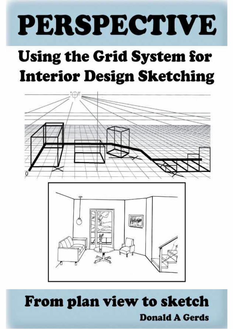
PERSPECTIVE: Using the Grid System for InteriorDesign Sketching: From plan view to sketch
By Donald Gerds
Copyright 2011 & 2012 by Donald Gerds
NOTICE: This work is copyrighted. It is licensed only for use by the original purchaser. Making copies of this work or distributing it to any unauthorizedperson by any means, including without limit e-mail, floppy disk, file transfer, paper print out, or any other method constitutes a violation of Internationalcopyright law and subjects the violator to severe fines or imprisonment.
This includes teachers and students who are giving out copies to other students thinking that it’s alright to make illegal copies just because it’s foreducational use. We teachers don’t make enough money as it is, please do not rip us off for the few bucks that this e-book costs. After all, this book costsless than a cup of fancy coffee and you would not walk out of a coffee store without paying..... Would you?
For more information about this book and other books and products go to the website:http://www.directartgoods.com/
E-book formatting and design by Eric Gerds
This is version 1.2 of this e-book.
Introduction: Perspective, The Grid System For InteriorDesign.
This electronic book is a rewrite of the original paper book about perspective drawingusing the grid system with a focus on doing interior design. This “E” book is to a sketch as thepaper back book is to a rendering. It will enable you to sketch an interior or a piece offurniture, in front of a client so that both of you are seeing the same thing you talked about. Inthe paper back book you have a full size grid, in this “E” book you will learn how to make themand use grids in a sketch.
The important part of an interior sketch is that if you can show a one point perspective ofa room with a chair turned at 45 degrees, the room will no longer seem like a one pointperspective.
The grid system is a simple and efficient way of learning perspective quickly andaccurately with a minimum of work and effort.
Perspective allows a designer to create the illusion of depth and dimension on a two-dimensional surface. Without successful perspective, no rendering will look accurate.However, with a correct perspective drawing, an object can be rendered quickly. `
Emphasis is also placed on the development of three-dimensional thinking through the useof the grid. The grid system of perspective is based on the cube; all other shapes can be draw inperspective by using the cube shape.
The prime purpose of the grid is to enable you, the designer, to draw any object with lesseffort and with more understanding. This book is designed to help you get right to the drawingwithout being lost in a volume of reading material.
Tips for using this book:
To see the illustrations and pictures better use your e-reader’s ability to zoom inand enlarge the images. If you have a touch screen double click on the image andthen use the pinch and zoom feature to enlarge the image. When you are done tapon the “X” symbol. If you do not have a touch screen, use your joy stick or arrowbuttons (called the 5-way controller) to put the cursor over the image. A small zoomicon with a plus sign appears. Press the 5-way controller to zoom in, then press itagain to zoom out. Press the next page button to return to the regular viewing ofthe book. Also, some images look better if you rotate your e-reader 90 degrees.
Understanding Perspective
Perspective is a naturally occurring event where objects closer to your eye seem largerand as they move farther away they appear smaller. It is when an artist, using traditional orcomputer methods, ignores perspective rules that the artwork looks wrong.
Understanding perspective is a matter of both theory and practice, and the theory ofperspective becomes easier in direct relationship to the amount of practical experience youundertake. Perspective allows a designer to create the illusion of depth and dimension on atwo-dimensional surface.
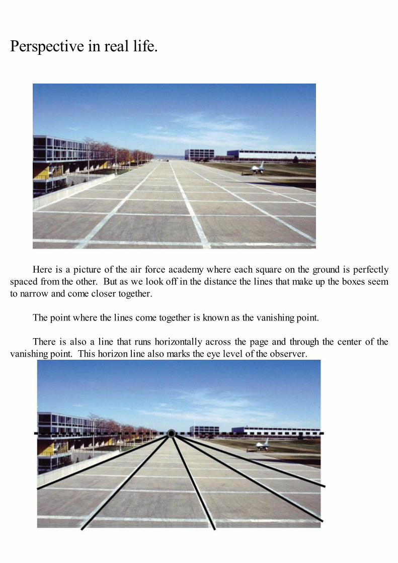
Perspective in real life.
Here is a picture of the air force academy where each square on the ground is perfectlyspaced from the other. But as we look off in the distance the lines that make up the boxes seemto narrow and come closer together.
The point where the lines come together is known as the vanishing point.
There is also a line that runs horizontally across the page and through the center of thevanishing point. This horizon line also marks the eye level of the observer.
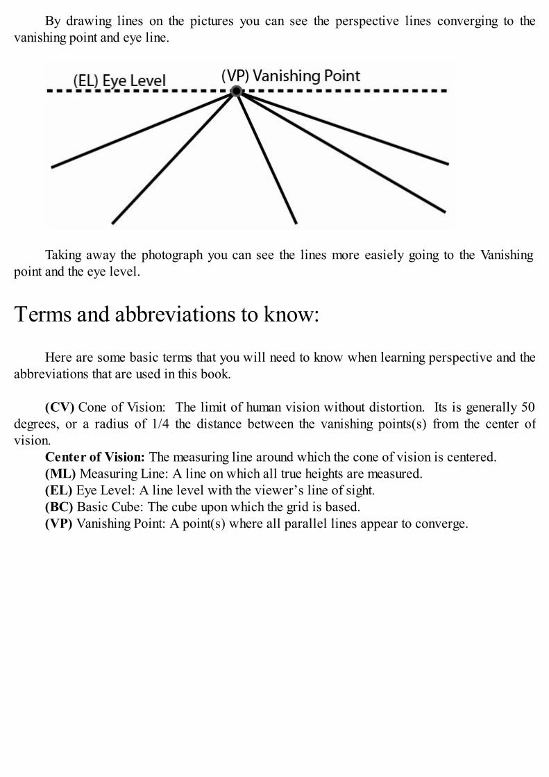
By drawing lines on the pictures you can see the perspective lines converging to thevanishing point and eye line.
Taking away the photograph you can see the lines more easiely going to the Vanishingpoint and the eye level.
Terms and abbreviations to know:
Here are some basic terms that you will need to know when learning perspective and theabbreviations that are used in this book.
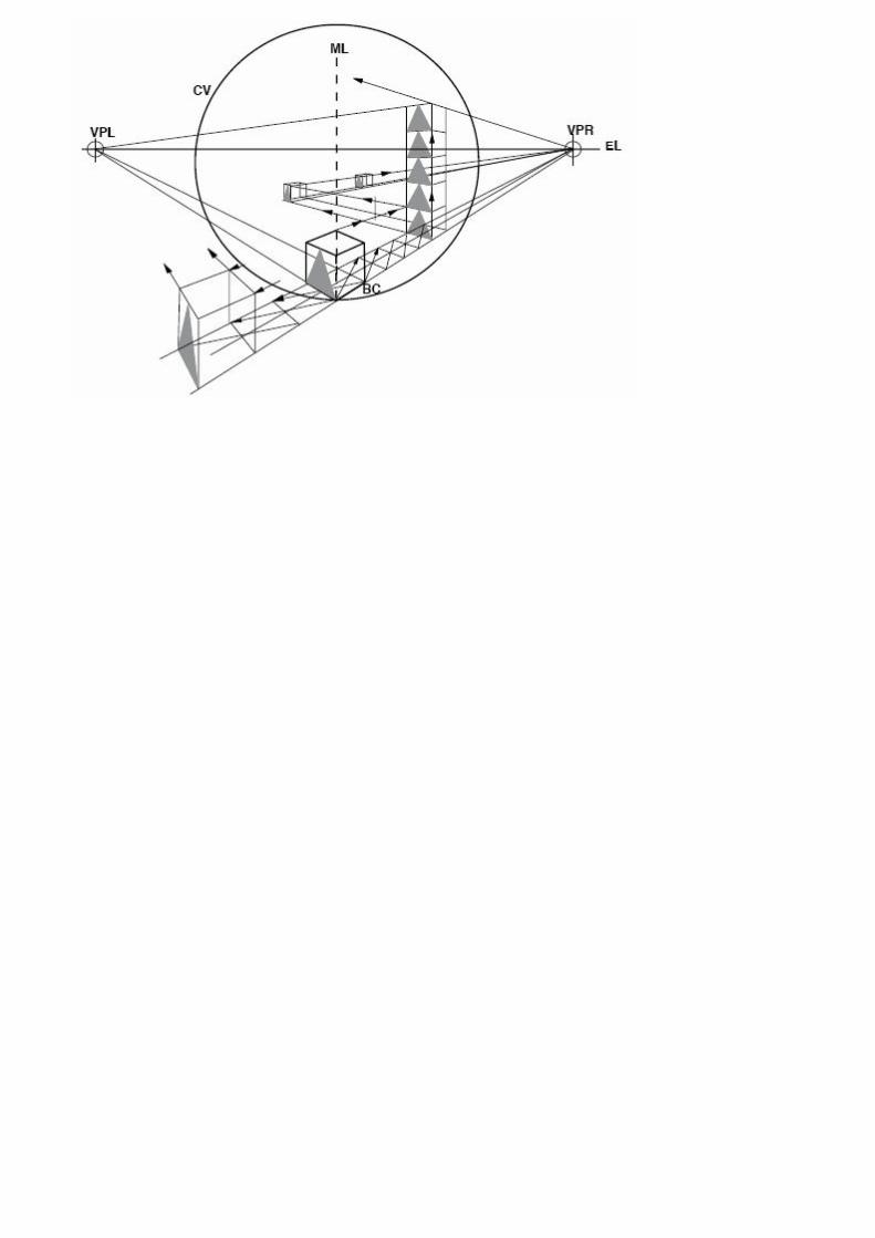
(CV) Cone of Vision: The limit of human vision without distortion. Its is generally 50degrees, or a radius of 1/4 the distance between the vanishing points(s) from the center ofvision.
Center of Vision: The measuring line around which the cone of vision is centered.(ML) Measuring Line: A line on which all true heights are measured.(EL) Eye Level: A line level with the viewer’s line of sight.(BC) Basic Cube: The cube upon which the grid is based.(VP) Vanishing Point: A point(s) where all parallel lines appear to converge.
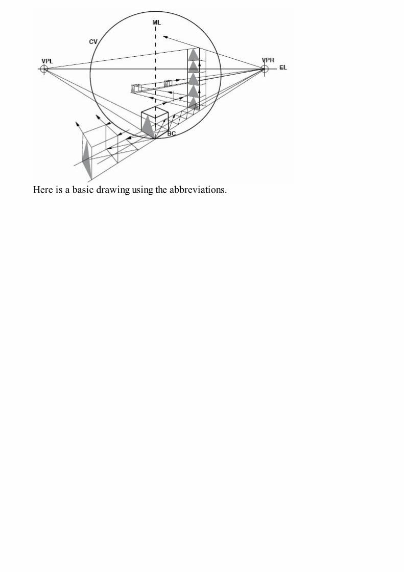
Here is a basic drawing using the abbreviations.
Understanding Views
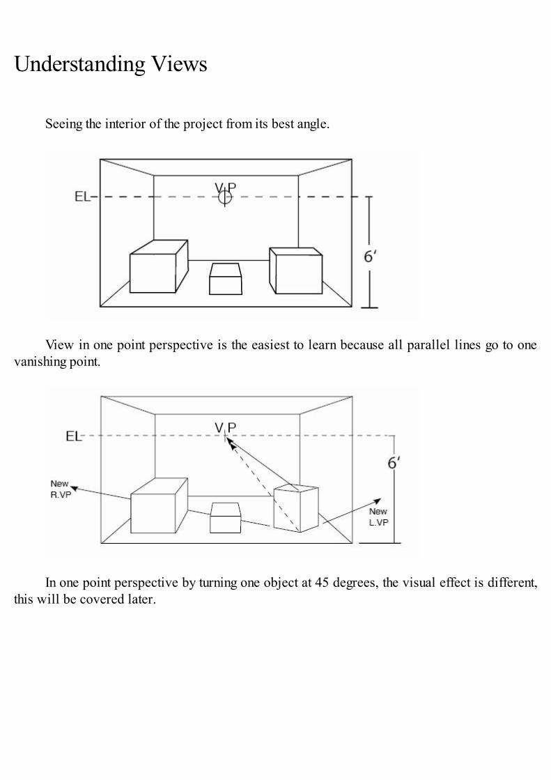
Seeing the interior of the project from its best angle.
View in one point perspective is the easiest to learn because all parallel lines go to onevanishing point.
In one point perspective by turning one object at 45 degrees, the visual effect is different,this will be covered later.
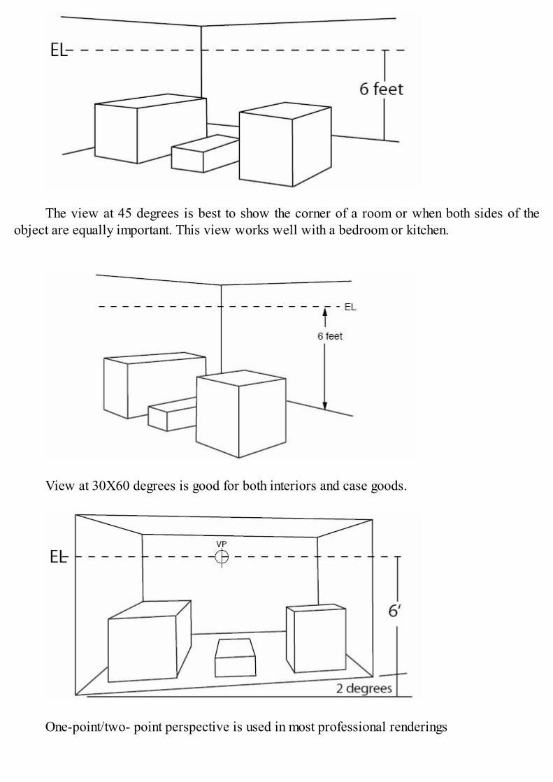
The view at 45 degrees is best to show the corner of a room or when both sides of theobject are equally important. This view works well with a bedroom or kitchen.
View at 30X60 degrees is good for both interiors and case goods.
One-point/two- point perspective is used in most professional renderings
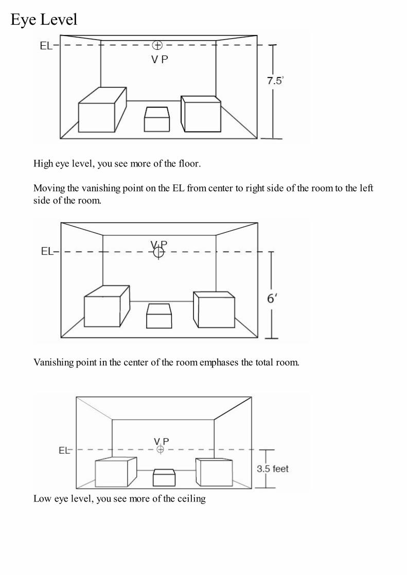
Eye Level
High eye level, you see more of the floor.
Moving the vanishing point on the EL from center to right side of the room to the leftside of the room.
Vanishing point in the center of the room emphases the total room.
Low eye level, you see more of the ceiling
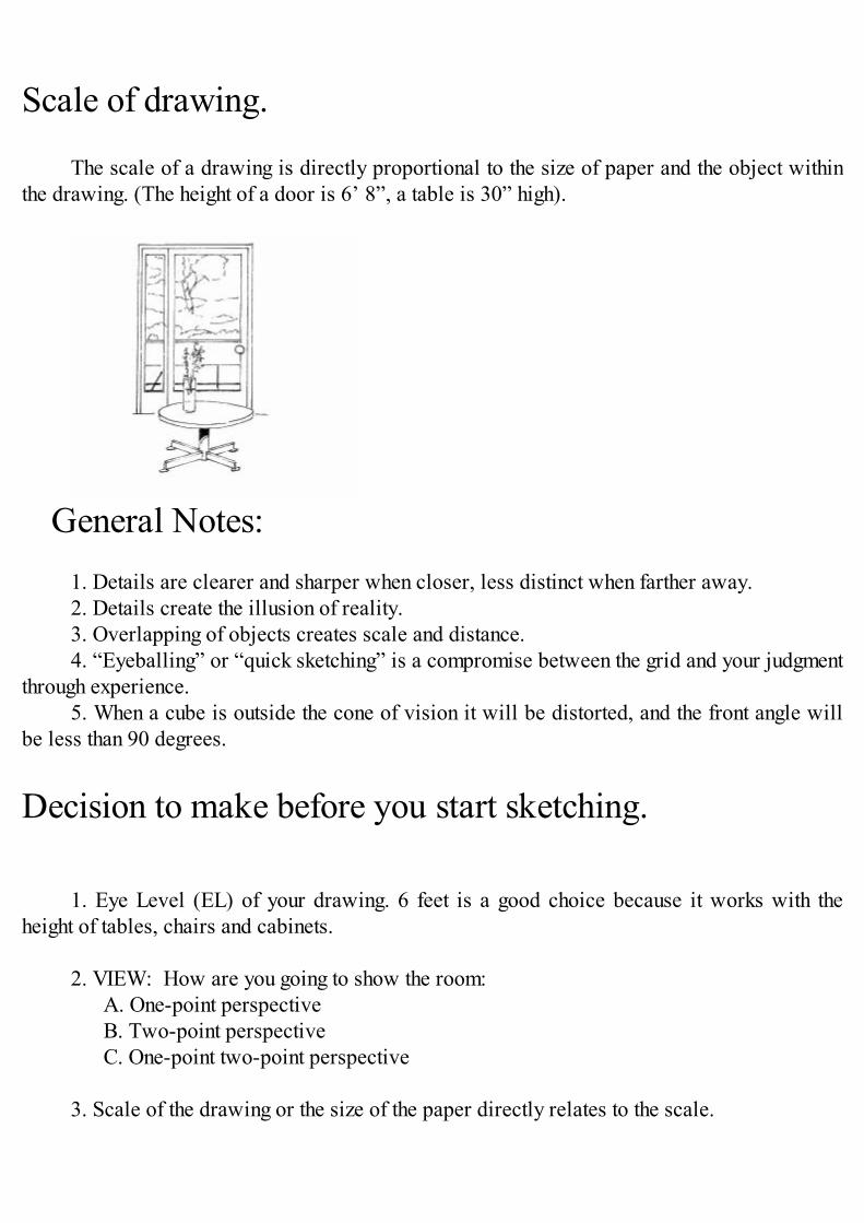
Scale of drawing.
The scale of a drawing is directly proportional to the size of paper and the object withinthe drawing. (The height of a door is 6’ 8”, a table is 30” high).
General Notes:1. Details are clearer and sharper when closer, less distinct when farther away.2. Details create the illusion of reality.3. Overlapping of objects creates scale and distance.4. “Eyeballing” or “quick sketching” is a compromise between the grid and your judgment
through experience.5. When a cube is outside the cone of vision it will be distorted, and the front angle will
be less than 90 degrees.
Decision to make before you start sketching.
1. Eye Level (EL) of your drawing. 6 feet is a good choice because it works with theheight of tables, chairs and cabinets.
2. VIEW: How are you going to show the room:A. One-point perspectiveB. Two-point perspectiveC. One-point two-point perspective
3. Scale of the drawing or the size of the paper directly relates to the scale.
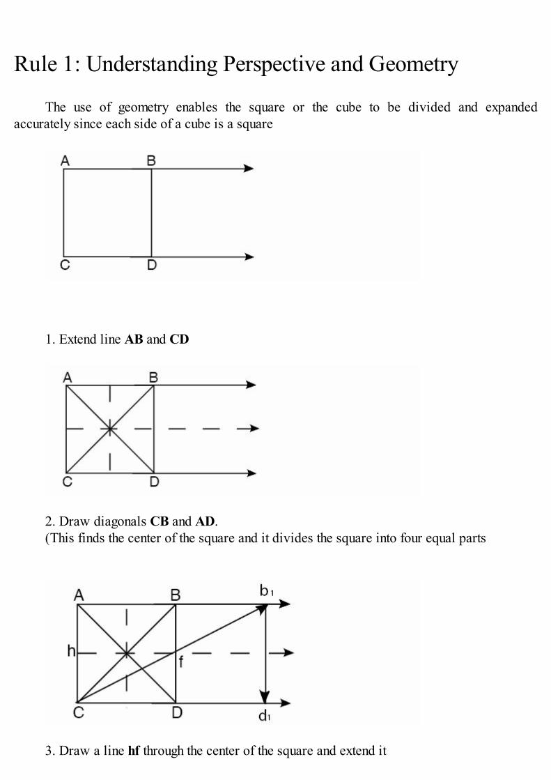
Rule 1: Understanding Perspective and Geometry
The use of geometry enables the square or the cube to be divided and expandedaccurately since each side of a cube is a square
1. Extend line AB and CD
2. Draw diagonals CB and AD.(This finds the center of the square and it divides the square into four equal parts
3. Draw a line hf through the center of the square and extend it

4. Draw diagonal line Cf to intersect line AB at .b1
5. Drop a vertical line from b1 to d1
6. Repeat, using D to h.
The same rule applies to perspective, but receding squares look smaller as they go to thevanishing point. You will see this in the next drawing.
1. Establish square ABCD (by grid or by eye).2. Extend line AB and DC to the vanishing point.3. Draw diagonal AD and BC (the intersection forms the center of the square ABCD.4. Extend line hf from center point to vanishing point.5. Draw diagonal Cf to intersect line AB at f16. Drop a vertical line from b and d.7. Repeat step 5 & 6 as needed.8. To bring the square toward you reverse step 5 & 6 through Df to a and drop line c.

Construction of a One Point Grid Layout
Using a one point grid with the vanishing point to the far left allows seeing the kitchencabinets. Choosing the location on the vanishing point in one point perspective is veryimportant.
This pencil sketch done by Pat Marovich located the vanishing point in about the center ofthe room to give a balanced design. Note the two chairs turned at 45 degrees which changes thelook of the interior. We will cover this later in the E-Book.
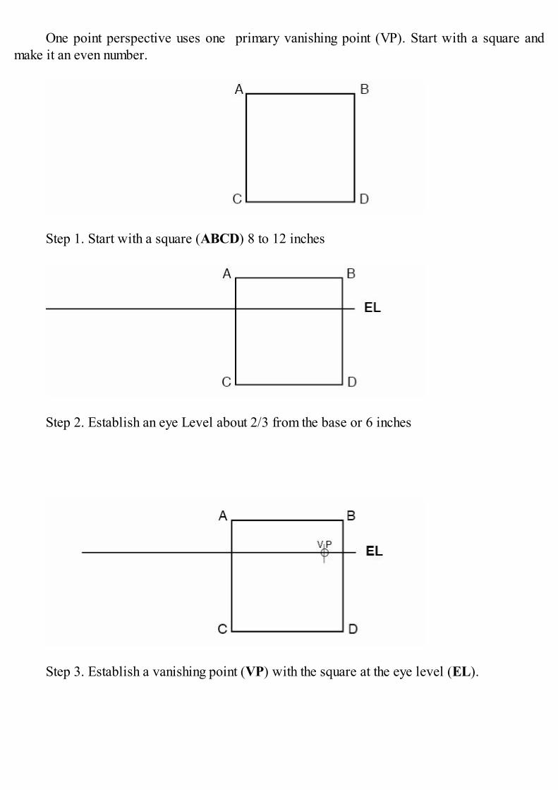
One point perspective uses one primary vanishing point (VP). Start with a square andmake it an even number.
Step 1. Start with a square (ABCD) 8 to 12 inches
Step 2. Establish an eye Level about 2/3 from the base or 6 inches
Step 3. Establish a vanishing point (VP) with the square at the eye level (EL).
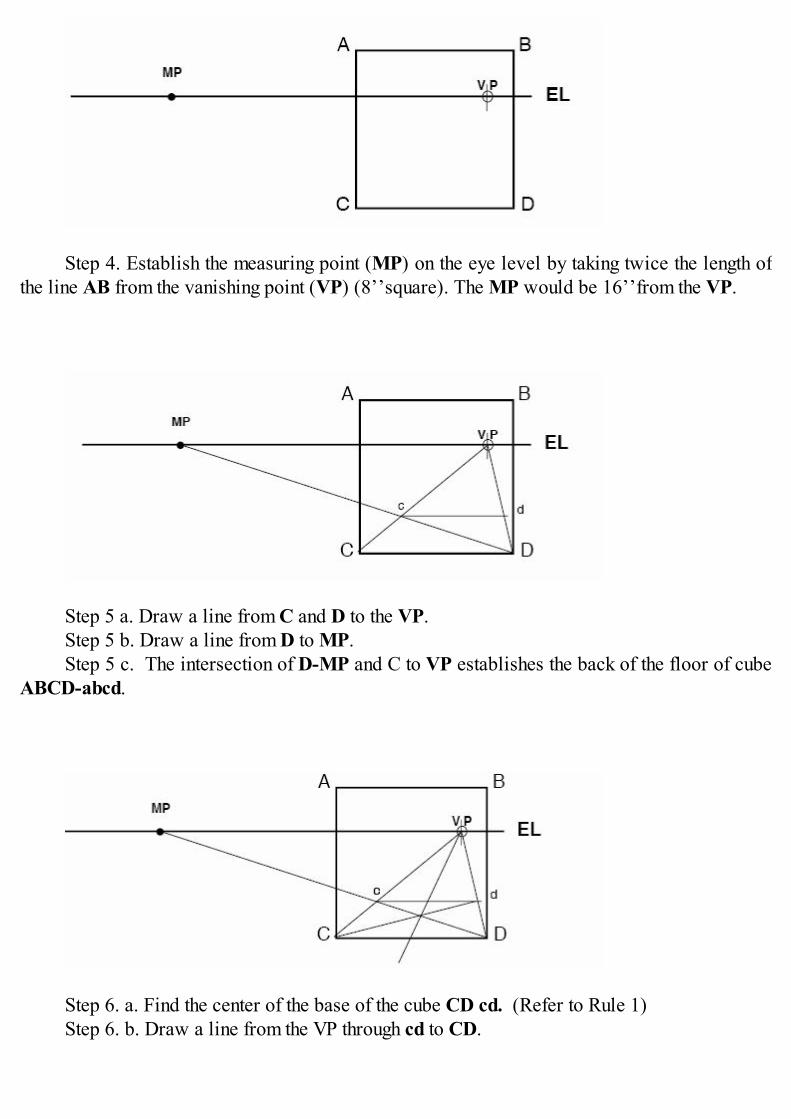
Step 4. Establish the measuring point (MP) on the eye level by taking twice the length ofthe line AB from the vanishing point (VP) (8’’square). The MP would be 16’’from the VP.
Step 5 a. Draw a line from C and D to the VP.Step 5 b. Draw a line from D to MP.Step 5 c. The intersection of D-MP and C to VP establishes the back of the floor of cube
ABCD-abcd.
Step 6. a. Find the center of the base of the cube CD cd. (Refer to Rule 1)Step 6. b. Draw a line from the VP through cd to CD.
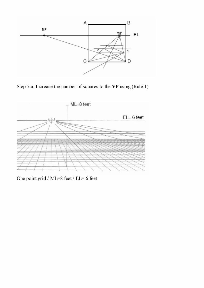
Step 7.a. Increase the number of squares to the VP using (Rule 1)
One point grid / ML=8 feet / EL= 6 feet

Construction of a 45 degree Grid layout.
Pencil sketch of a trade show display using a 45 degree grid.
Using a 45 degree grid is ideal when you’re showing the corner of a room.
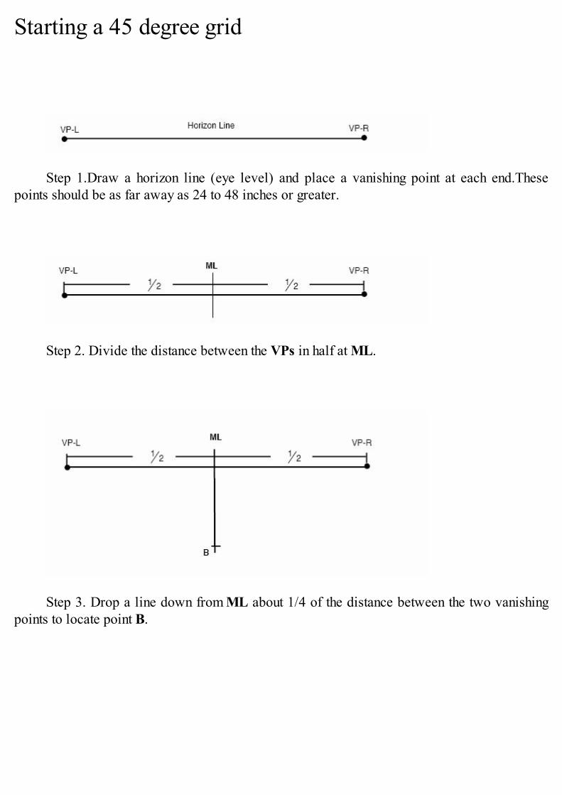
Starting a 45 degree grid
Step 1.Draw a horizon line (eye level) and place a vanishing point at each end.Thesepoints should be as far away as 24 to 48 inches or greater.
Step 2. Divide the distance between the VPs in half at ML.
Step 3. Drop a line down from ML about 1/4 of the distance between the two vanishingpoints to locate point B.
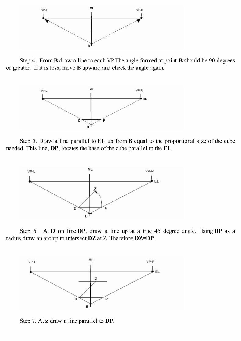
Step 4. From B draw a line to each VP.The angle formed at point B should be 90 degreesor greater. If it is less, move B upward and check the angle again.
Step 5. Draw a line parallel to EL up from B equal to the proportional size of the cubeneeded. This line, DP, locates the base of the cube parallel to the EL.
Step 6. At D on line DP, draw a line up at a true 45 degree angle. Using DP as aradius,draw an arc up to intersect DZ at Z. Therefore DZ=DP.
Step 7. At z draw a line parallel to DP.
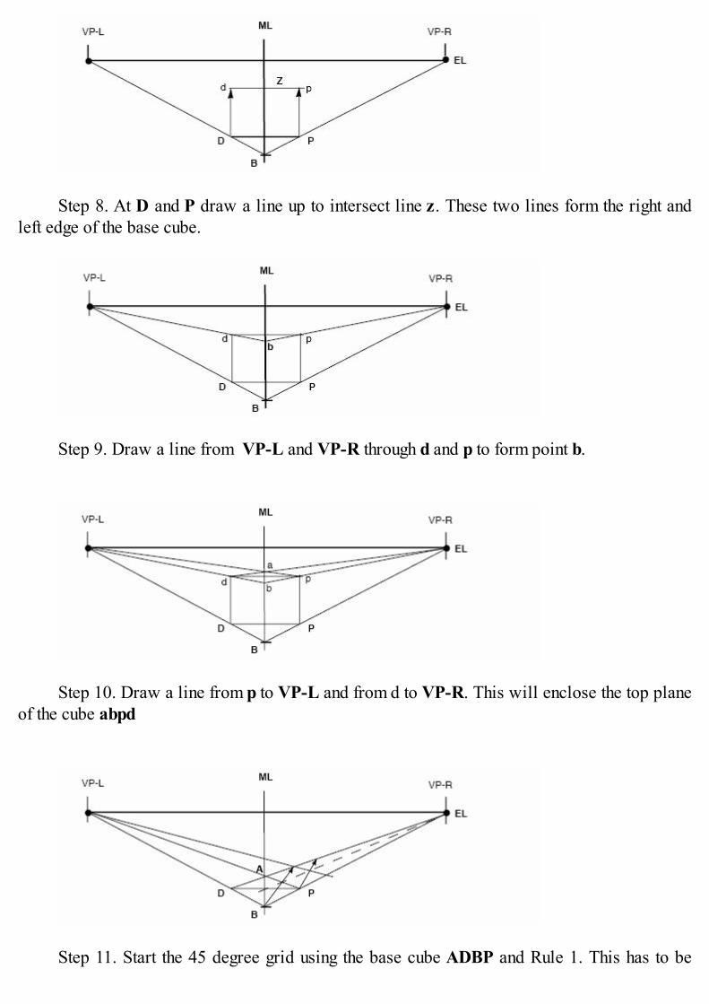
Step 8. At D and P draw a line up to intersect line z. These two lines form the right andleft edge of the base cube.
Step 9. Draw a line from VP-L and VP-R through d and p to form point b.
Step 10. Draw a line from p to VP-L and from d to VP-R. This will enclose the top planeof the cube abpd
Step 11. Start the 45 degree grid using the base cube ADBP and Rule 1. This has to be
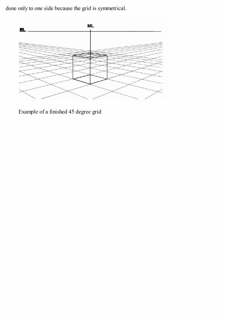
done only to one side because the grid is symmetrical.
Example of a finished 45 degree grid
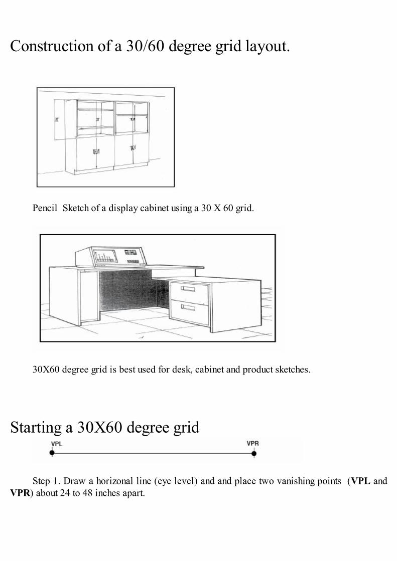
Construction of a 30/60 degree grid layout.
Pencil Sketch of a display cabinet using a 30 X 60 grid.
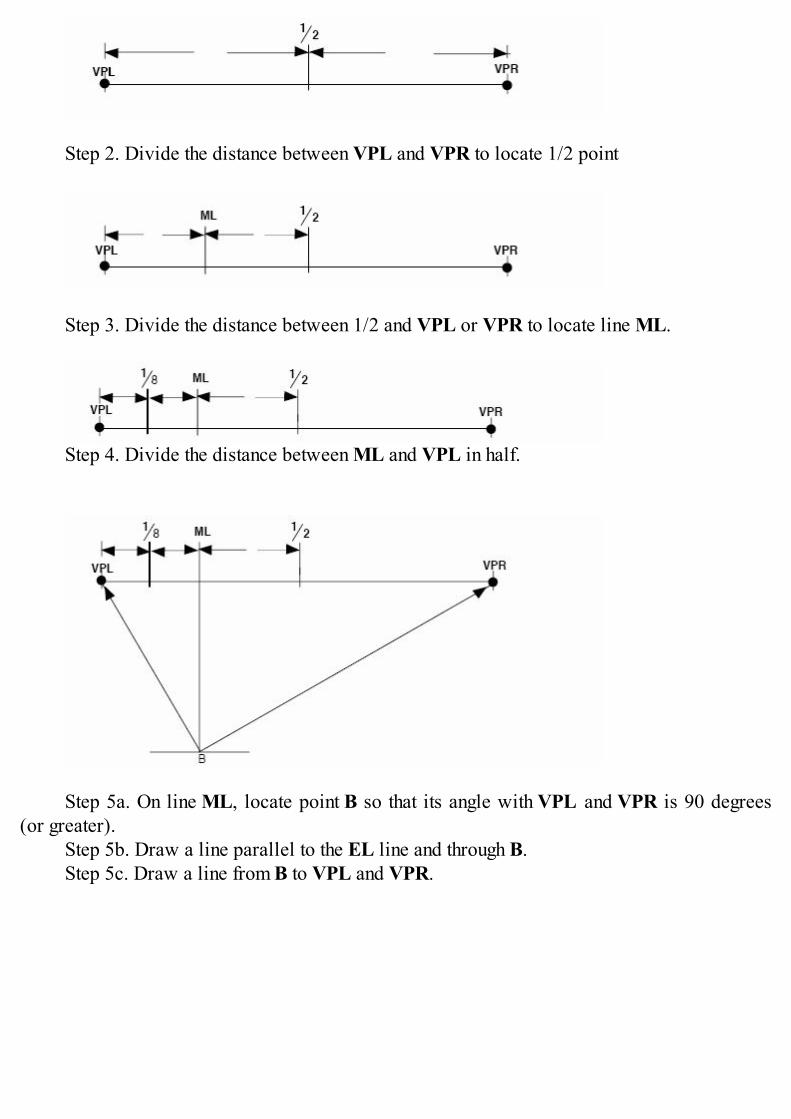
30X60 degree grid is best used for desk, cabinet and product sketches.
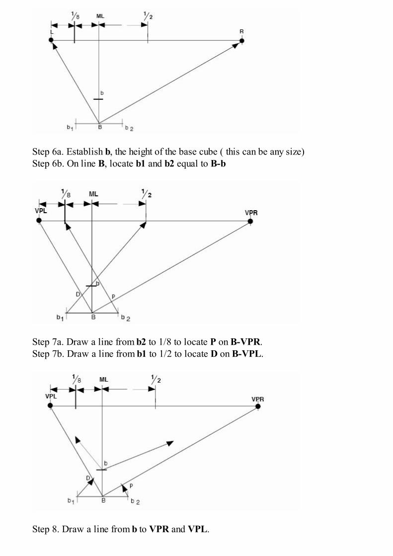
Starting a 30X60 degree grid
Step 1. Draw a horizonal line (eye level) and and place two vanishing points (VPL andVPR) about 24 to 48 inches apart.
Step 2. Divide the distance between VPL and VPR to locate 1/2 point
Step 3. Divide the distance between 1/2 and VPL or VPR to locate line ML.
Step 4. Divide the distance between ML and VPL in half.
Step 5a. On line ML, locate point B so that its angle with VPL and VPR is 90 degrees(or greater).
Step 5b. Draw a line parallel to the EL line and through B.Step 5c. Draw a line from B to VPL and VPR.
Step 6a. Establish b, the height of the base cube ( this can be any size)Step 6b. On line B, locate b1 and b2 equal to B-b
Step 7a. Draw a line from b2 to 1/8 to locate P on B-VPR.Step 7b. Draw a line from b1 to 1/2 to locate D on B-VPL.
Step 8. Draw a line from b to VPR and VPL.
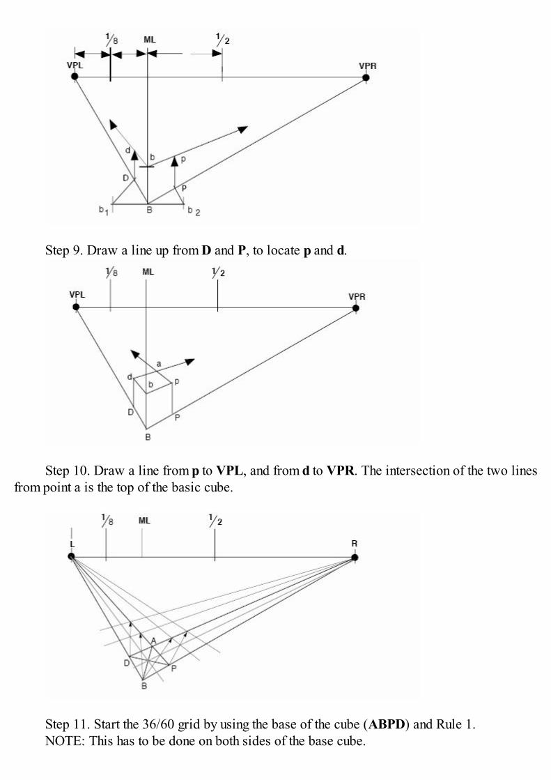
Step 9. Draw a line up from D and P, to locate p and d.
Step 10. Draw a line from p to VPL, and from d to VPR. The intersection of the two linesfrom point a is the top of the basic cube.
Step 11. Start the 36/60 grid by using the base of the cube (ABPD) and Rule 1.NOTE: This has to be done on both sides of the base cube.
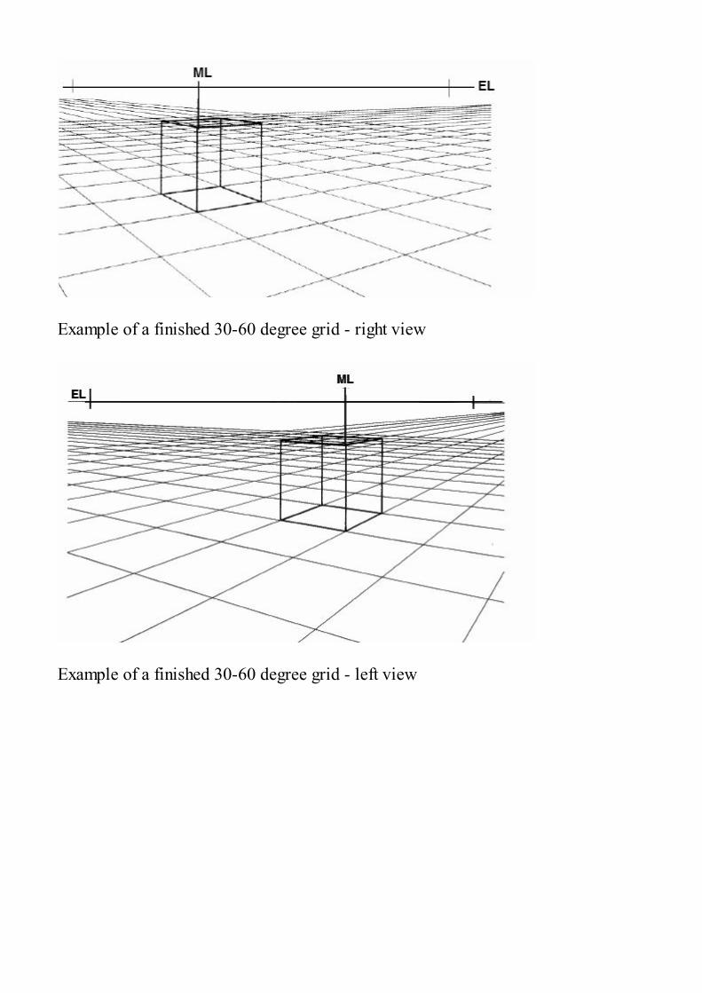
Example of a finished 30-60 degree grid - right view
Example of a finished 30-60 degree grid - left view
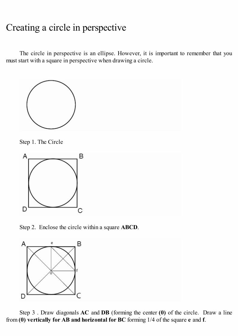
Creating a circle in perspective
The circle in perspective is an ellipse. However, it is important to remember that youmust start with a square in perspective when drawing a circle.
Step 1. The Circle
Step 2. Enclose the circle within a square ABCD.
Step 3 . Draw diagonals AC and DB (forming the center (0) of the circle. Draw a linefrom (0) vertically for AB and horizontal for BC forming 1/4 of the square e and f.
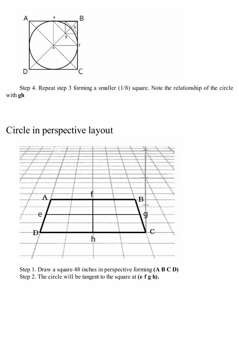
Step 4. Repeat step 3 forming a smaller (1/8) square. Note the relationship of the circlewith gh
Circle in perspective layout
Step 1. Draw a square 48 inches in perspective forming (A B C D) Step 2. The circle will be tangent to the square at (e f g h).
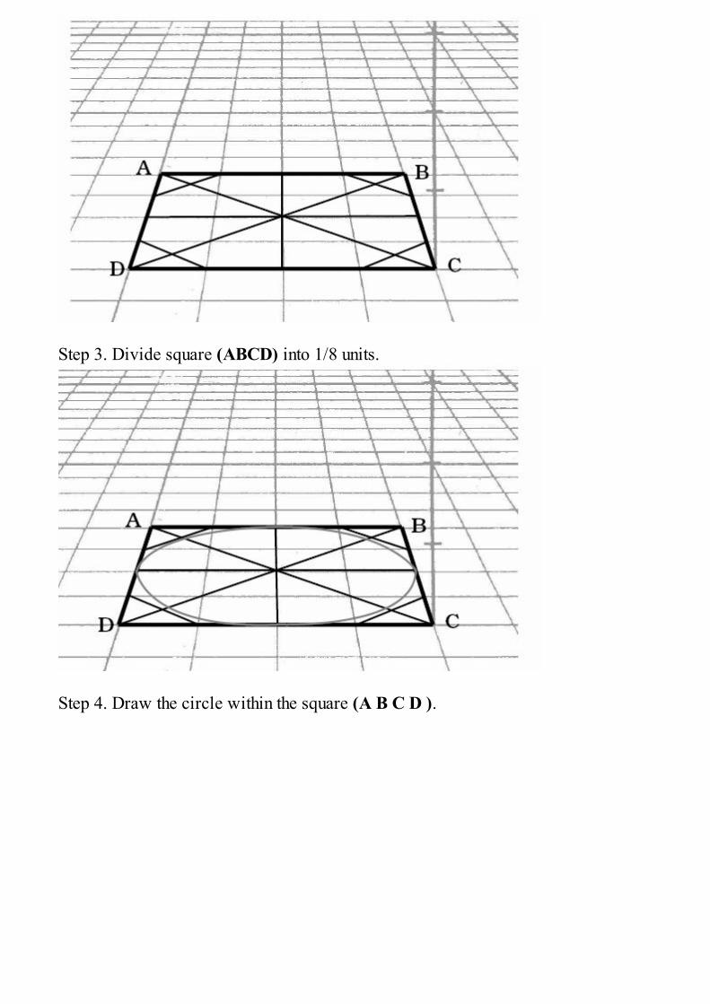
Step 3. Divide square (ABCD) into 1/8 units.
Step 4. Draw the circle within the square (A B C D ).
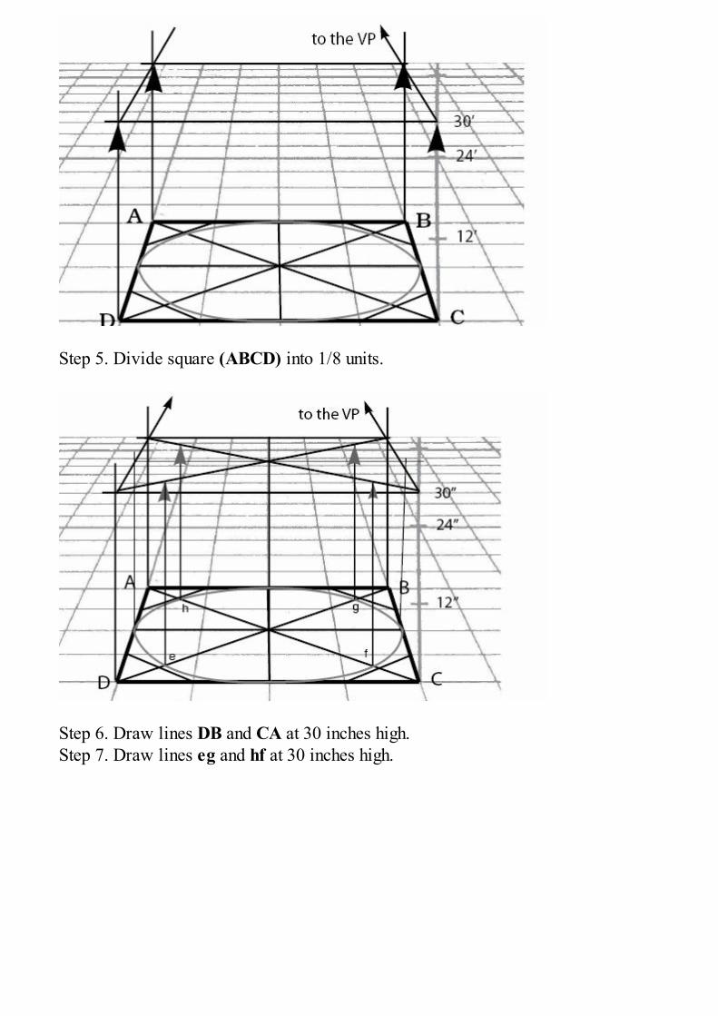
Step 5. Divide square (ABCD) into 1/8 units.
Step 6. Draw lines DB and CA at 30 inches high.Step 7. Draw lines eg and hf at 30 inches high.
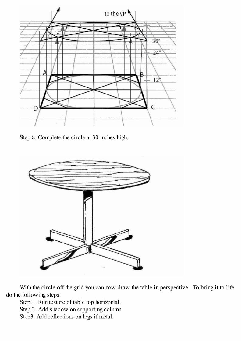
Step 8. Complete the circle at 30 inches high.
With the circle off the grid you can now draw the table in perspective. To bring it to lifedo the following steps.
Step1. Run texture of table top horizontal.Step 2. Add shadow on supporting columnStep3. Add reflections on legs if metal.
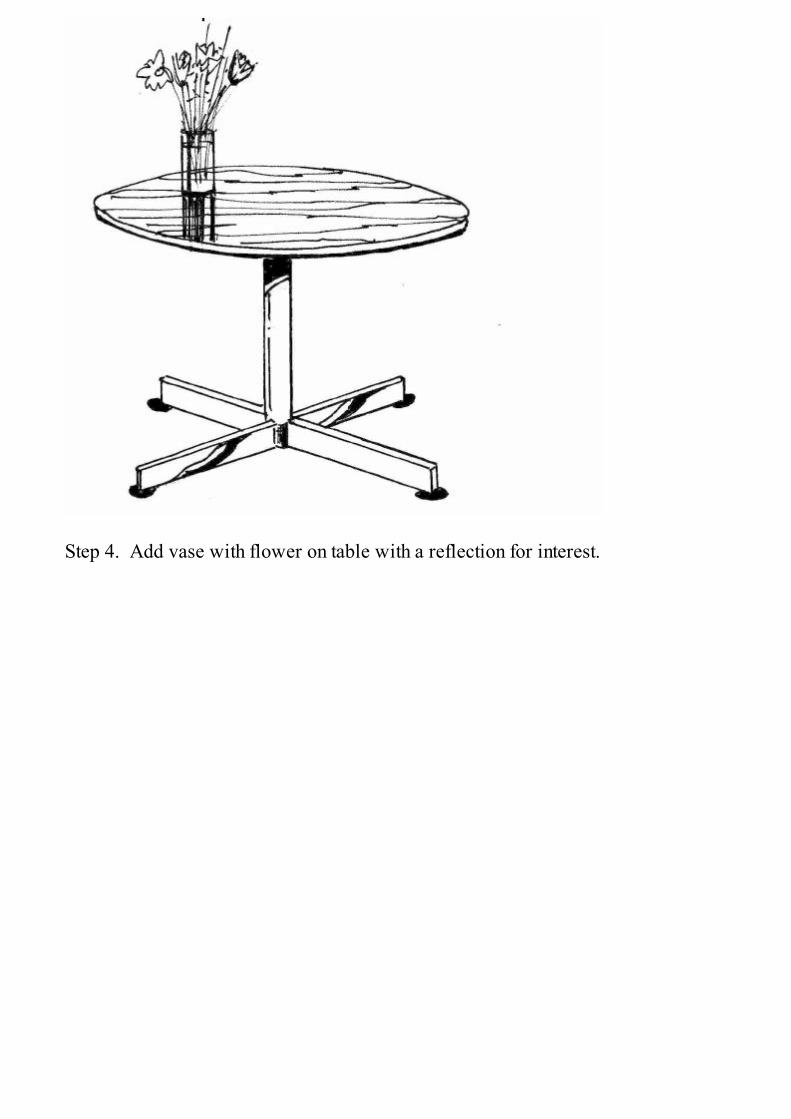
Step 4. Add vase with flower on table with a reflection for interest.
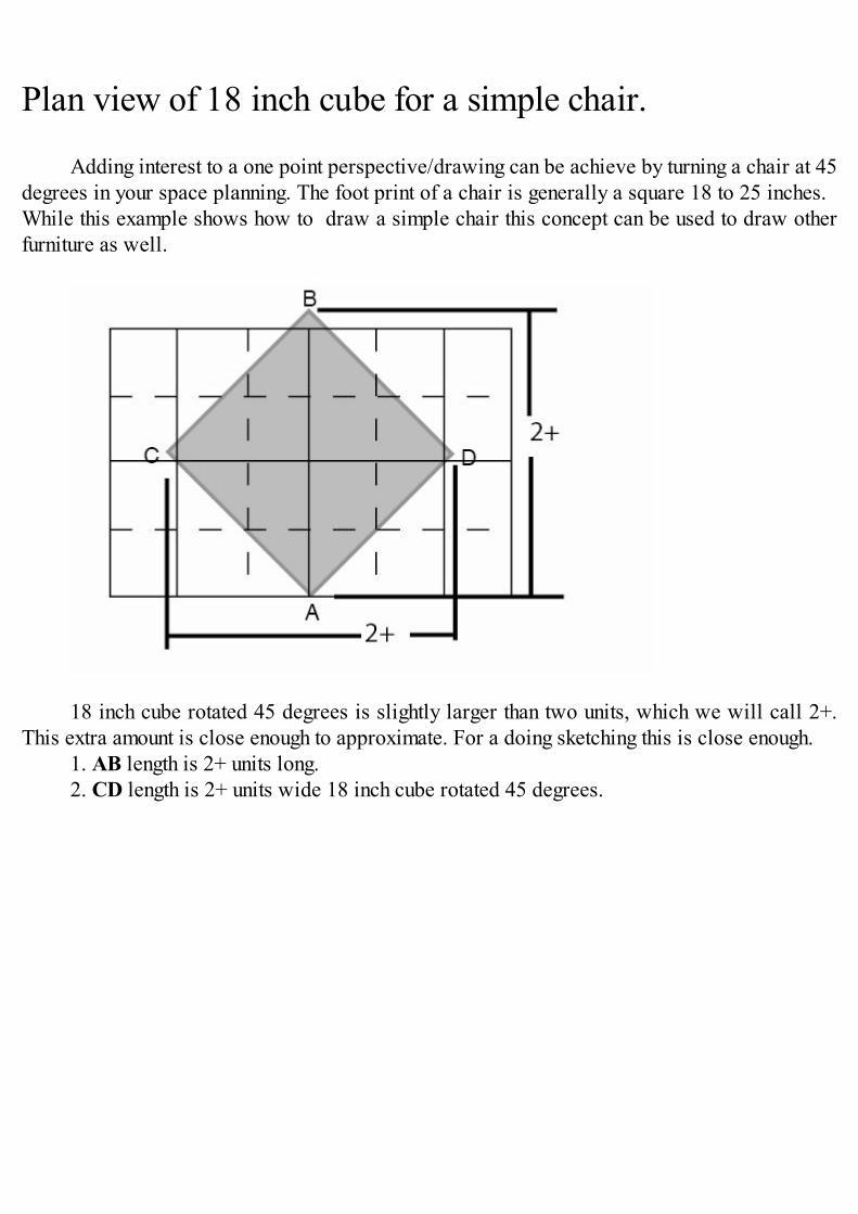
Plan view of 18 inch cube for a simple chair.
Adding interest to a one point perspective/drawing can be achieve by turning a chair at 45degrees in your space planning. The foot print of a chair is generally a square 18 to 25 inches. While this example shows how to draw a simple chair this concept can be used to draw otherfurniture as well.
18 inch cube rotated 45 degrees is slightly larger than two units, which we will call 2+.This extra amount is close enough to approximate. For a doing sketching this is close enough.
1. AB length is 2+ units long.2. CD length is 2+ units wide 18 inch cube rotated 45 degrees.
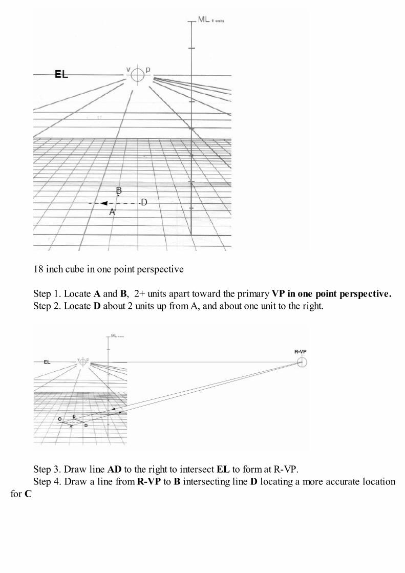
18 inch cube in one point perspective
Step 1. Locate A and B, 2+ units apart toward the primary VP in one point perspective.Step 2. Locate D about 2 units up from A, and about one unit to the right.
Step 3. Draw line AD to the right to intersect EL to form at R-VP.Step 4. Draw a line from R-VP to B intersecting line D locating a more accurate location
for C
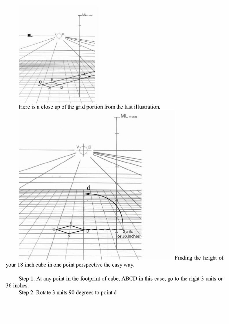
Here is a close up of the grid portion from the last illustration.
Finding the height ofyour 18 inch cube in one point perspective the easy way.
Step 1. At any point in the footprint of cube, ABCD in this case, go to the right 3 units or36 inches.
Step 2. Rotate 3 units 90 degrees to point d
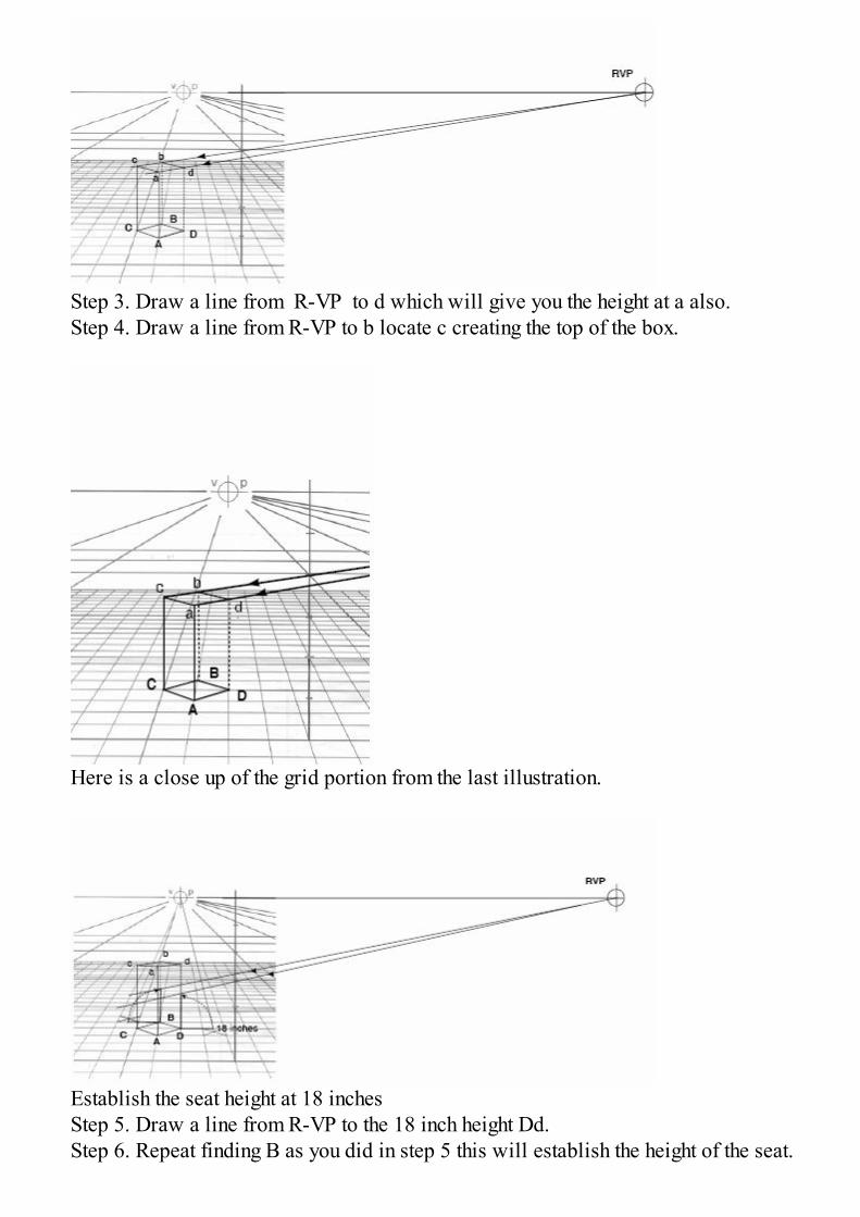
Step 3. Draw a line from R-VP to d which will give you the height at a also.Step 4. Draw a line from R-VP to b locate c creating the top of the box.
Here is a close up of the grid portion from the last illustration.
Establish the seat height at 18 inchesStep 5. Draw a line from R-VP to the 18 inch height Dd.Step 6. Repeat finding B as you did in step 5 this will establish the height of the seat.
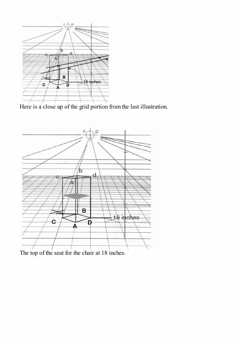
Here is a close up of the grid portion from the last illustration.
The top of the seat for the chair at 18 inches.
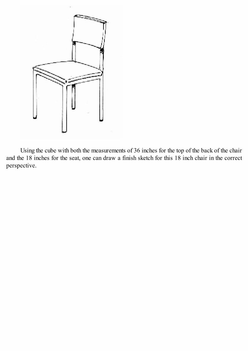
Using the cube with both the measurements of 36 inches for the top of the back of the chairand the 18 inches for the seat, one can draw a finish sketch for this 18 inch chair in the correctperspective.

Plan view of 24 inch cube for a lounge chair
To create a more traditional lounge chair at a 45 degree angle in a room start with 24 inchcube rotated 45 degrees. Like the last cube we sketched we are going to be approximate on thegrid size.
1. AB length is 2 3/4 units long2. CD length is 2 3/4 units wide

Step 1. Locate A and B, 2 and 3 quarters units toward the primary VP in 1 pointperspective.
Step 2. Locate CD about 1 1/2 units up from A. (Remember that a unit is 12 inches and 11/2 units is close enough count as 18 inches for sketching)
Step 3. Locate D about 1 1/2 units to the right of the center line.Step 4. C will be located in the next step.
Step 5. Draw a line AD to the right to intersect EL to form at R-VP for ADBC cube.Step 6. Draw a line from R-VP to B intersecting line D locating a more accurate location
for C.
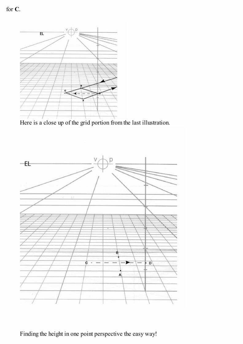
Here is a close up of the grid portion from the last illustration.
Finding the height in one point perspective the easy way!
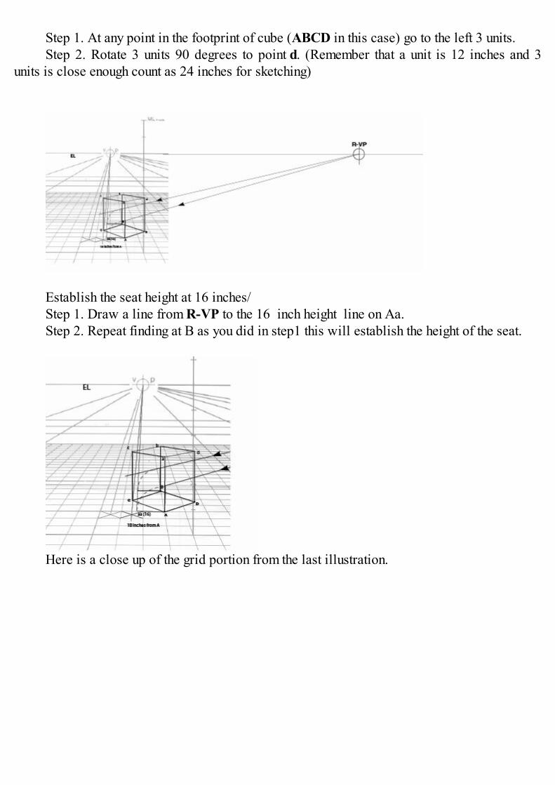
Step 1. At any point in the footprint of cube (ABCD in this case) go to the left 3 units.Step 2. Rotate 3 units 90 degrees to point d. (Remember that a unit is 12 inches and 3
units is close enough count as 24 inches for sketching)
Establish the seat height at 16 inches/Step 1. Draw a line from R-VP to the 16 inch height line on Aa.Step 2. Repeat finding at B as you did in step1 this will establish the height of the seat.
Here is a close up of the grid portion from the last illustration.
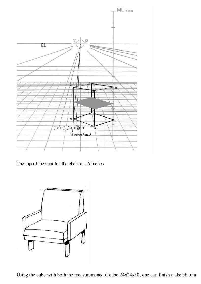
The top of the seat for the chair at 16 inches
Using the cube with both the measurements of cube 24x24x30, one can finish a sketch of a

more traditional lounge chair in the correct perspective.
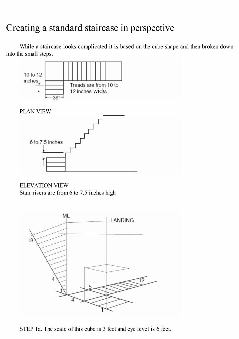
Creating a standard staircase in perspective
While a staircase looks complicated it is based on the cube shape and then broken downinto the small steps.
PLAN VIEW
ELEVATION VIEWStair risers are from 6 to 7.5 inches high
STEP 1a. The scale of this cube is 3 feet and eye level is 6 feet.
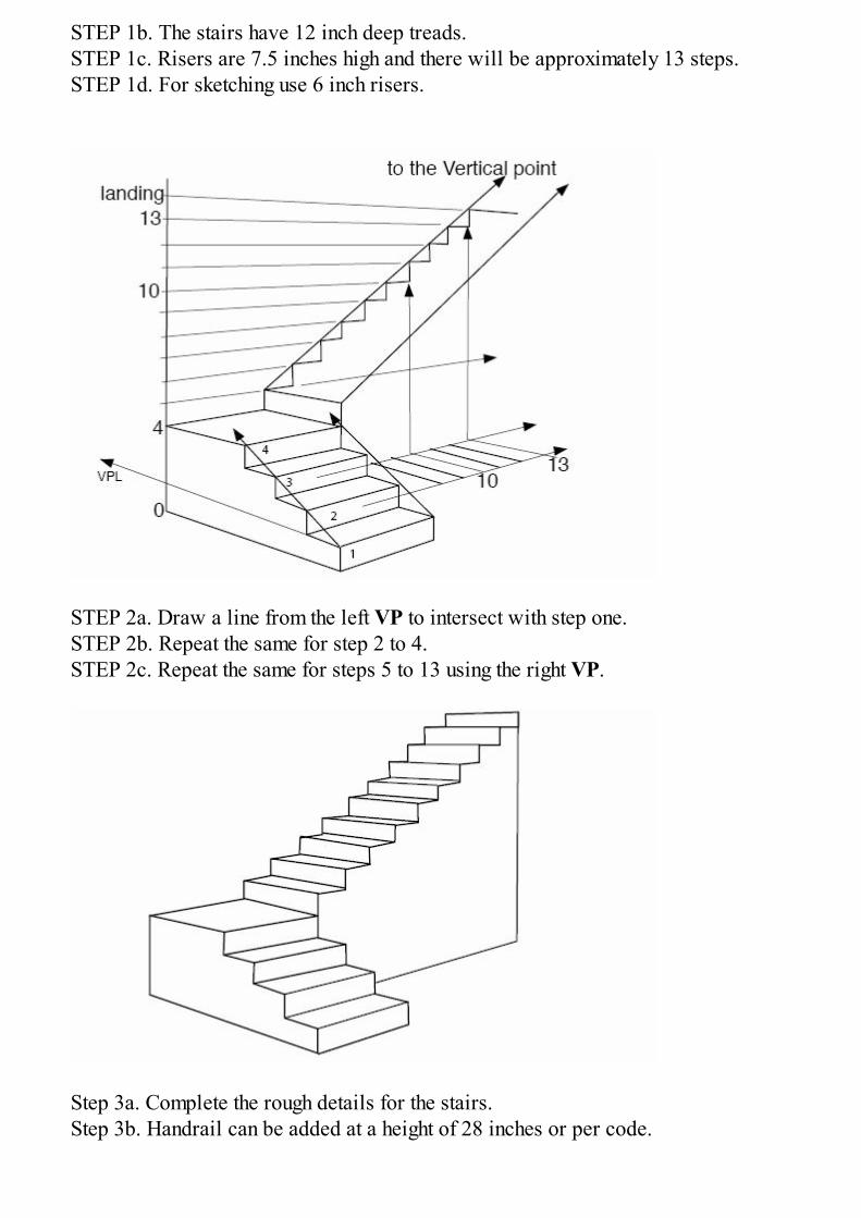
STEP 1b. The stairs have 12 inch deep treads.STEP 1c. Risers are 7.5 inches high and there will be approximately 13 steps.STEP 1d. For sketching use 6 inch risers.
STEP 2a. Draw a line from the left VP to intersect with step one.STEP 2b. Repeat the same for step 2 to 4.STEP 2c. Repeat the same for steps 5 to 13 using the right VP.
Step 3a. Complete the rough details for the stairs.Step 3b. Handrail can be added at a height of 28 inches or per code.
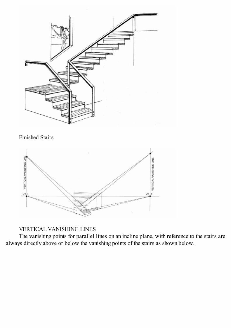
Finished Stairs
VERTICAL VANISHING LINESThe vanishing points for parallel lines on an incline plane, with reference to the stairs are
always directly above or below the vanishing points of the stairs as shown below.
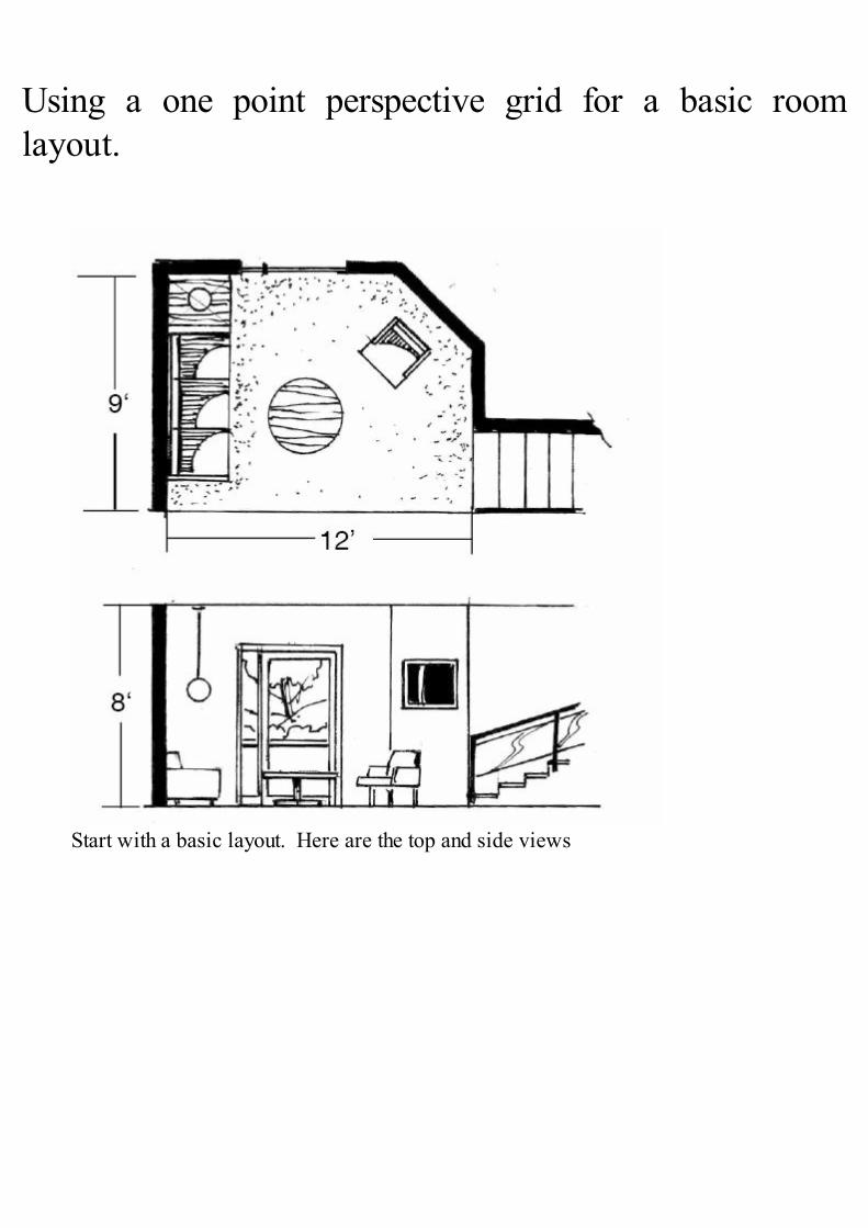
Using a one point perspective grid for a basic roomlayout.
Start with a basic layout. Here are the top and side views
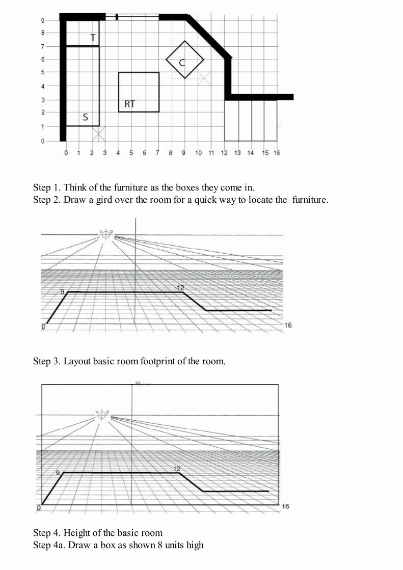
Step 1. Think of the furniture as the boxes they come in.Step 2. Draw a gird over the room for a quick way to locate the furniture.
Step 3. Layout basic room footprint of the room.
Step 4. Height of the basic roomStep 4a. Draw a box as shown 8 units high

Step 4a. The width should be at least 16 units wide.
Step 5a. Draw a line up at 12 up to 8 high.Step 5b. From 0 and 12 up draw a line to the VP.
Step 6a draw a line up at the back of the room from 9 and 12 to connect with 0 and 12 tothe VP forming the back wall.
Step 6b. Draw a line up from 12c up at the stairs corner.
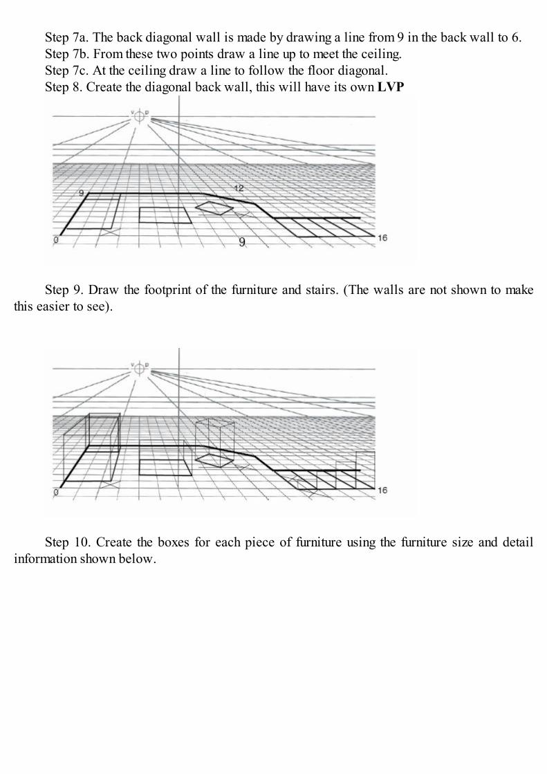
Step 7a. The back diagonal wall is made by drawing a line from 9 in the back wall to 6.Step 7b. From these two points draw a line up to meet the ceiling.Step 7c. At the ceiling draw a line to follow the floor diagonal.Step 8. Create the diagonal back wall, this will have its own LVP
Step 9. Draw the footprint of the furniture and stairs. (The walls are not shown to makethis easier to see).
Step 10. Create the boxes for each piece of furniture using the furniture size and detailinformation shown below.
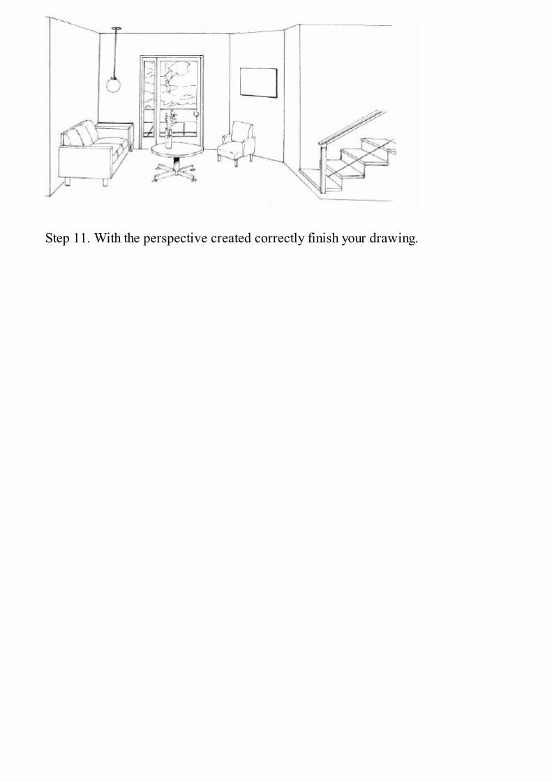
Step 11. With the perspective created correctly finish your drawing.
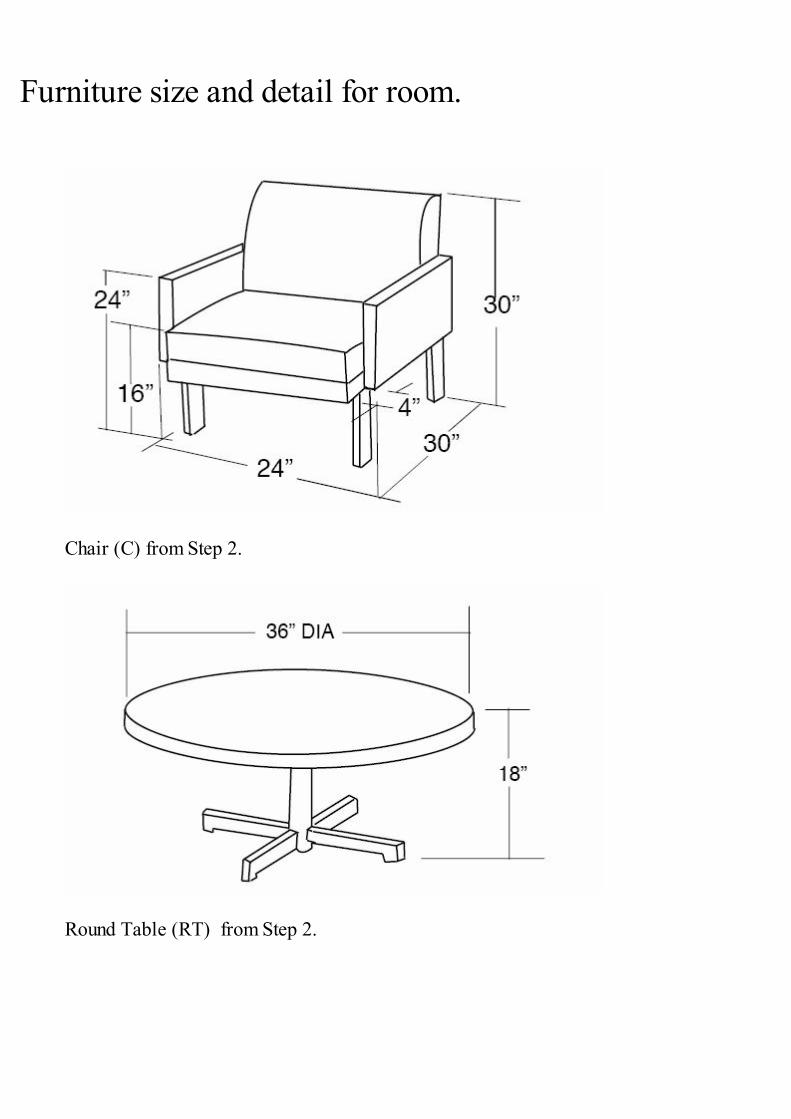
Furniture size and detail for room.
Chair (C) from Step 2.
Round Table (RT) from Step 2.

Storage unit (T) from Step 2.
SOFA (S) from Step 2.
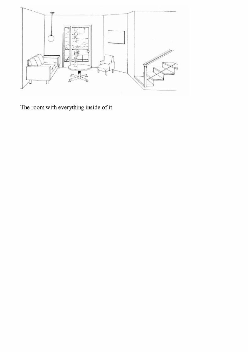
The room with everything inside of it
About the Author.
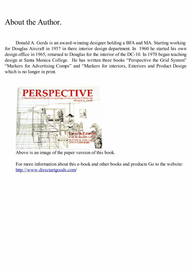
Donald A. Gerds is an award-winning designer holding a BFA and MA. Starting workingfor Douglas Aircraft in 1957 in there interior design department. In 1960 he started his owndesign office in 1965, returned to Douglas for the interior of the DC-10. In 1970 began teachingdesign at Santa Monica College. He has written three books “Perspective the Grid System”“Markers for Advertising Comps” and “Markers for interiors, Exteriors and Product Designwhich is no longer in print.
Above is an image of the paper version of this book.
For more information about this e-book and other books and products Go to the website:http://www.directartgoods.com/
Others books By Donald Gerds:
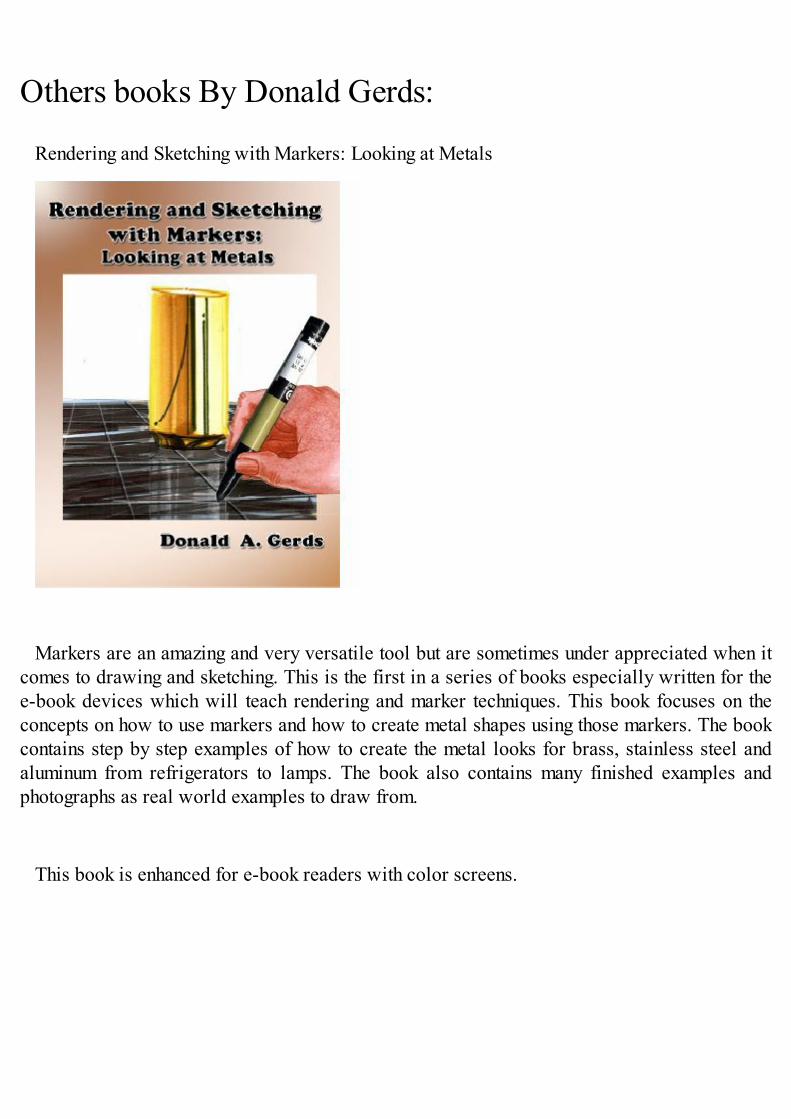
Rendering and Sketching with Markers: Looking at Metals
Markers are an amazing and very versatile tool but are sometimes under appreciated when itcomes to drawing and sketching. This is the first in a series of books especially written for thee-book devices which will teach rendering and marker techniques. This book focuses on theconcepts on how to use markers and how to create metal shapes using those markers. The bookcontains step by step examples of how to create the metal looks for brass, stainless steel andaluminum from refrigerators to lamps. The book also contains many finished examples andphotographs as real world examples to draw from.
This book is enhanced for e-book readers with color screens.
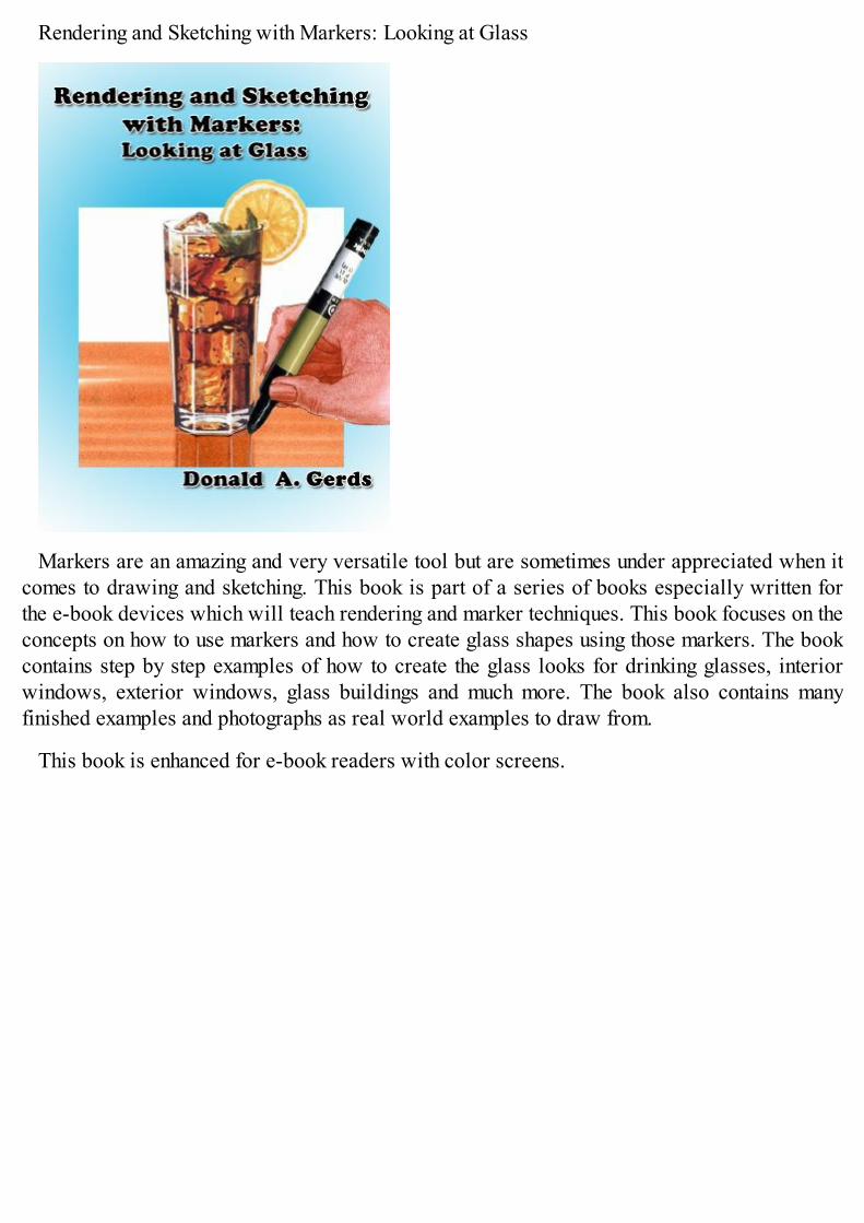
Rendering and Sketching with Markers: Looking at Glass
Markers are an amazing and very versatile tool but are sometimes under appreciated when itcomes to drawing and sketching. This book is part of a series of books especially written forthe e-book devices which will teach rendering and marker techniques. This book focuses on theconcepts on how to use markers and how to create glass shapes using those markers. The bookcontains step by step examples of how to create the glass looks for drinking glasses, interiorwindows, exterior windows, glass buildings and much more. The book also contains manyfinished examples and photographs as real world examples to draw from.
This book is enhanced for e-book readers with color screens.

Table of ContentsIntroduction: Perspective, The Grid System For Interior Design.Tips for using this book:Understanding PerspectivePerspective in real life.Terms and abbreviations to know:Understanding ViewsScale of drawing.Decision to make before you start sketching.Rule 1: Understanding Perspective and GeometryConstruction of a One Point Grid LayoutConstruction of a 45 degree Grid layout.Construction of a 30/60 degree grid layout.Creating a circle in perspectivePlan view of 18 inch cube for a simple chair.Plan view of 24 inch cube for a lounge chairCreating a standard staircase in perspectiveUsing a one point perspective grid for a basic room layout.Furniture size and detail for room.About the Author.Others books By Donald Gerds: