Embed Size (px)
Citation preview

CalVert High-Speed V/STOL Personal Transport
Department of Aerospace Engineering
University of Maryland
College Park, Maryland 20740
June 30, 1999
University of Maryland
Alfred Gessow Rotorcraft Center
Department of Aerospace Engineering
University of Maryland, College Park
Maryland, 20742
CalVert High-Speed V/STOL Personal Transport
In response to the 1999 Annual American Helicopter Society
Student Design Competition - Graduate Category
30 June 1999
Nikhil Koratkar - Team Leader Dr. Inderjit Chopra - Faculty Advisor
Nicolas Costes William Horn
Vijay Madhavan Hun Park
Harsha Prahlad Paul Samuel
Mark Shaner

Acknowledgements
First and foremost, we would like to thank Prof. Marat Tishchenko for his guidance, advice,
recommendations, insights and above all for his friendship. We are grateful to Dr V.T Nagaraj for his
overall guidance and for arranging our visit to Kaman Helicopters. Special thanks are due to Prof.
Alfred Gessow for his encouragement and careful examination of the design report. Finally, we would
like to thank Prof. Inderjit Chopra for establishing the design course at the University of Maryland
and giving us exposure to the fascinating world of Helicopter Design.

Contents
List of Figures vi
List of Tables viii
Abbreviations and Symbols ix
Proposal Requirements Matrix x
Executive Summary 1
1 Introduction 5
2 Aircraft Con�guration Trade Study 6
2.1 Candidate con�gurations . . . . . . . . . . . . . . . . . . . . . . . . . . . . . . . . . . . . 6
2.2 Preliminary downselection . . . . . . . . . . . . . . . . . . . . . . . . . . . . . . . . . . . 8
2.3 Compound helicopter vs. tilt rotor . . . . . . . . . . . . . . . . . . . . . . . . . . . . . . 10
2.3.1 Engine, aerodynamic and weight models . . . . . . . . . . . . . . . . . . . . . . . 11
2.3.2 Economic model and comparison indices . . . . . . . . . . . . . . . . . . . . . . . 11
2.3.3 Mission pro�le . . . . . . . . . . . . . . . . . . . . . . . . . . . . . . . . . . . . . 12
2.3.4 Trade study methodology . . . . . . . . . . . . . . . . . . . . . . . . . . . . . . . 12
2.3.5 Trade study results . . . . . . . . . . . . . . . . . . . . . . . . . . . . . . . . . . . 13
2.3.6 Downselection . . . . . . . . . . . . . . . . . . . . . . . . . . . . . . . . . . . . . 16
2.4 Compound con�guration trade studies . . . . . . . . . . . . . . . . . . . . . . . . . . . . 18
2.4.1 Thrust compounding mechanism . . . . . . . . . . . . . . . . . . . . . . . . . . . 18
2.4.2 High wing vs. low wing . . . . . . . . . . . . . . . . . . . . . . . . . . . . . . . . 19
2.4.3 Single main rotor vs. dual main rotors . . . . . . . . . . . . . . . . . . . . . . . . 20
2.4.4 Landing gear . . . . . . . . . . . . . . . . . . . . . . . . . . . . . . . . . . . . . . 21
2.4.5 Number of blades . . . . . . . . . . . . . . . . . . . . . . . . . . . . . . . . . . . . 22
2.5 Conclusion . . . . . . . . . . . . . . . . . . . . . . . . . . . . . . . . . . . . . . . . . . . 23
3 Aircraft Level Description 24
3.1 Thrust and lift compounding . . . . . . . . . . . . . . . . . . . . . . . . . . . . . . . . . 26
3.2 Variable RPM power plant . . . . . . . . . . . . . . . . . . . . . . . . . . . . . . . . . . 26
3.3 Low drag design features . . . . . . . . . . . . . . . . . . . . . . . . . . . . . . . . . . . . 26
3.4 Advanced active systems . . . . . . . . . . . . . . . . . . . . . . . . . . . . . . . . . . . . 29
3.5 Variable payload con�gurations . . . . . . . . . . . . . . . . . . . . . . . . . . . . . . . . 29
3.6 Mission adaptability . . . . . . . . . . . . . . . . . . . . . . . . . . . . . . . . . . . . . . 29
3.7 Maximum mission readiness . . . . . . . . . . . . . . . . . . . . . . . . . . . . . . . . . . 30
ii

4 Calvert: Detailed Design 30
4.1 Main rotor and hub design . . . . . . . . . . . . . . . . . . . . . . . . . . . . . . . . . . . 30
4.1.1 Rotor system . . . . . . . . . . . . . . . . . . . . . . . . . . . . . . . . . . . . . . 30
4.1.2 Airfoil selection . . . . . . . . . . . . . . . . . . . . . . . . . . . . . . . . . . . . . 30
4.1.3 Hub design . . . . . . . . . . . . . . . . . . . . . . . . . . . . . . . . . . . . . . . 32
4.2 Rotor blade dynamics and stability . . . . . . . . . . . . . . . . . . . . . . . . . . . . . . 33
4.3 Rotor blade kinematics and clearances . . . . . . . . . . . . . . . . . . . . . . . . . . . . 36
4.4 Vibration and noise issues . . . . . . . . . . . . . . . . . . . . . . . . . . . . . . . . . . . 38
4.4.1 Vibration reduction: passive design features . . . . . . . . . . . . . . . . . . . . . 38
4.4.2 Active vibration control . . . . . . . . . . . . . . . . . . . . . . . . . . . . . . . . 38
4.4.3 SMA-actuated in ight tracking tab . . . . . . . . . . . . . . . . . . . . . . . . . . 39
4.4.4 Noise issues . . . . . . . . . . . . . . . . . . . . . . . . . . . . . . . . . . . . . . . 40
4.5 Propeller design . . . . . . . . . . . . . . . . . . . . . . . . . . . . . . . . . . . . . . . . . 41
4.5.1 Con�guration . . . . . . . . . . . . . . . . . . . . . . . . . . . . . . . . . . . . . . 41
4.5.2 Shaft . . . . . . . . . . . . . . . . . . . . . . . . . . . . . . . . . . . . . . . . . . . 42
4.6 Wing . . . . . . . . . . . . . . . . . . . . . . . . . . . . . . . . . . . . . . . . . . . . . . . 42
4.7 Empennage sizing . . . . . . . . . . . . . . . . . . . . . . . . . . . . . . . . . . . . . . . 43
4.8 Engine . . . . . . . . . . . . . . . . . . . . . . . . . . . . . . . . . . . . . . . . . . . . . . 44
4.8.1 Characteristics . . . . . . . . . . . . . . . . . . . . . . . . . . . . . . . . . . . . . 44
4.8.2 Performance . . . . . . . . . . . . . . . . . . . . . . . . . . . . . . . . . . . . . . 45
4.8.3 Structural integration . . . . . . . . . . . . . . . . . . . . . . . . . . . . . . . . . 45
4.8.4 Oil system . . . . . . . . . . . . . . . . . . . . . . . . . . . . . . . . . . . . . . . . 46
4.8.5 Particle separator . . . . . . . . . . . . . . . . . . . . . . . . . . . . . . . . . . . 46
4.8.6 FADEC . . . . . . . . . . . . . . . . . . . . . . . . . . . . . . . . . . . . . . . . . 46
4.8.7 Safety . . . . . . . . . . . . . . . . . . . . . . . . . . . . . . . . . . . . . . . . . . 46
4.9 Transmission design . . . . . . . . . . . . . . . . . . . . . . . . . . . . . . . . . . . . . . 47
4.9.1 Con�guration . . . . . . . . . . . . . . . . . . . . . . . . . . . . . . . . . . . . . . 47
4.9.2 Structural integration . . . . . . . . . . . . . . . . . . . . . . . . . . . . . . . . . 48
4.9.3 Housing . . . . . . . . . . . . . . . . . . . . . . . . . . . . . . . . . . . . . . . . . 49
4.9.4 Oil system . . . . . . . . . . . . . . . . . . . . . . . . . . . . . . . . . . . . . . . . 49
4.9.5 Summary of transmission advanced technologies . . . . . . . . . . . . . . . . . . 50
4.10 Landing gear design . . . . . . . . . . . . . . . . . . . . . . . . . . . . . . . . . . . . . . 52
4.10.1 Con�guration . . . . . . . . . . . . . . . . . . . . . . . . . . . . . . . . . . . . . . 52
4.10.2 Tire sizing . . . . . . . . . . . . . . . . . . . . . . . . . . . . . . . . . . . . . . . . 53
4.10.3 Oleo sizing . . . . . . . . . . . . . . . . . . . . . . . . . . . . . . . . . . . . . . . 53
4.11 Airframe . . . . . . . . . . . . . . . . . . . . . . . . . . . . . . . . . . . . . . . . . . . . . 54
4.11.1 Substructure . . . . . . . . . . . . . . . . . . . . . . . . . . . . . . . . . . . . . . 54
4.11.2 Tail boom . . . . . . . . . . . . . . . . . . . . . . . . . . . . . . . . . . . . . . . . 54
4.11.3 Pylons . . . . . . . . . . . . . . . . . . . . . . . . . . . . . . . . . . . . . . . . . . 54
4.12 Subsystems . . . . . . . . . . . . . . . . . . . . . . . . . . . . . . . . . . . . . . . . . . . 54
4.12.1 Inlet and exhaust system . . . . . . . . . . . . . . . . . . . . . . . . . . . . . . . 54
4.12.2 Fuel system . . . . . . . . . . . . . . . . . . . . . . . . . . . . . . . . . . . . . . . 55
iii

4.12.3 Fire protection systems . . . . . . . . . . . . . . . . . . . . . . . . . . . . . . . . 55
4.12.4 Heating, ventilation, air conditioning, and anti-ice (HVACAI) system . . . . . . . 55
4.13 Interior layout . . . . . . . . . . . . . . . . . . . . . . . . . . . . . . . . . . . . . . . . . 56
4.13.1 Cabin . . . . . . . . . . . . . . . . . . . . . . . . . . . . . . . . . . . . . . . . . . 56
4.13.2 Doors . . . . . . . . . . . . . . . . . . . . . . . . . . . . . . . . . . . . . . . . . . 56
4.13.3 Cockpit controls . . . . . . . . . . . . . . . . . . . . . . . . . . . . . . . . . . . . 56
4.14 Reliability and maintainability . . . . . . . . . . . . . . . . . . . . . . . . . . . . . . . . 57
4.14.1 Accessibility . . . . . . . . . . . . . . . . . . . . . . . . . . . . . . . . . . . . . . . 57
4.14.2 Prognostics and health management . . . . . . . . . . . . . . . . . . . . . . . . . 57
4.14.3 Flight data system . . . . . . . . . . . . . . . . . . . . . . . . . . . . . . . . . . . 59
4.14.4 Vibratory database . . . . . . . . . . . . . . . . . . . . . . . . . . . . . . . . . . . 59
4.14.5 Information age . . . . . . . . . . . . . . . . . . . . . . . . . . . . . . . . . . . . . 59
4.15 Aircraft operation . . . . . . . . . . . . . . . . . . . . . . . . . . . . . . . . . . . . . . . 60
4.15.1 ISA and ISA+20 ight pro�le . . . . . . . . . . . . . . . . . . . . . . . . . . . . . 60
4.15.2 Flight procedures and instructions . . . . . . . . . . . . . . . . . . . . . . . . . . 60
4.15.3 OEI procedures . . . . . . . . . . . . . . . . . . . . . . . . . . . . . . . . . . . . . 61
4.15.4 Autorotation characteristics . . . . . . . . . . . . . . . . . . . . . . . . . . . . . . 62
4.15.5 Special safety provisions . . . . . . . . . . . . . . . . . . . . . . . . . . . . . . . . 64
5 Weight and Balance 64
5.1 Weight estimation . . . . . . . . . . . . . . . . . . . . . . . . . . . . . . . . . . . . . . . 65
5.2 Weight breakdown . . . . . . . . . . . . . . . . . . . . . . . . . . . . . . . . . . . . . . . 65
5.3 Weight e�ciency . . . . . . . . . . . . . . . . . . . . . . . . . . . . . . . . . . . . . . . . 68
5.4 CG travel . . . . . . . . . . . . . . . . . . . . . . . . . . . . . . . . . . . . . . . . . . . . 68
6 Performance 69
6.1 Drag breakdown . . . . . . . . . . . . . . . . . . . . . . . . . . . . . . . . . . . . . . . . 70
6.2 Performance analysis: methodology . . . . . . . . . . . . . . . . . . . . . . . . . . . . . . 71
6.3 Performance analysis: results . . . . . . . . . . . . . . . . . . . . . . . . . . . . . . . . . 74
7 Manufacturing 81
7.1 Technology . . . . . . . . . . . . . . . . . . . . . . . . . . . . . . . . . . . . . . . . . . . 81
7.2 Lean manufacturing . . . . . . . . . . . . . . . . . . . . . . . . . . . . . . . . . . . . . . 81
7.3 Manufacturing details . . . . . . . . . . . . . . . . . . . . . . . . . . . . . . . . . . . . . 81
7.3.1 Primary structure . . . . . . . . . . . . . . . . . . . . . . . . . . . . . . . . . . . 81
7.3.2 Jigs . . . . . . . . . . . . . . . . . . . . . . . . . . . . . . . . . . . . . . . . . . . 82
7.3.3 Frame . . . . . . . . . . . . . . . . . . . . . . . . . . . . . . . . . . . . . . . . . . 83
7.3.4 Composite panels . . . . . . . . . . . . . . . . . . . . . . . . . . . . . . . . . . . . 83
7.3.5 Rotor blades . . . . . . . . . . . . . . . . . . . . . . . . . . . . . . . . . . . . . . 83
7.3.6 Rotor hub . . . . . . . . . . . . . . . . . . . . . . . . . . . . . . . . . . . . . . . . 85
7.3.7 Propeller . . . . . . . . . . . . . . . . . . . . . . . . . . . . . . . . . . . . . . . . 85
7.3.8 Wing . . . . . . . . . . . . . . . . . . . . . . . . . . . . . . . . . . . . . . . . . . 86
iv

8 Cost Analysis 86
8.1 Purchase price . . . . . . . . . . . . . . . . . . . . . . . . . . . . . . . . . . . . . . . . . 86
8.2 Cost model . . . . . . . . . . . . . . . . . . . . . . . . . . . . . . . . . . . . . . . . . . . 86
9 Alternate Flight Modes 89
9.1 6-passenger maximum cruise speed . . . . . . . . . . . . . . . . . . . . . . . . . . . . . . 90
9.2 6-passenger maximum range . . . . . . . . . . . . . . . . . . . . . . . . . . . . . . . . . . 90
9.3 Maximum payload mode . . . . . . . . . . . . . . . . . . . . . . . . . . . . . . . . . . . . 90
9.4 Surveillance/search and rescue . . . . . . . . . . . . . . . . . . . . . . . . . . . . . . . . 90
9.5 Performance comparison . . . . . . . . . . . . . . . . . . . . . . . . . . . . . . . . . . . . 90
10 Summary and Conclusions 91
Bibliography 93
MIL-STD-1374 Weight Statement 96
v

List of Figures
0.1 Calvert highlights. . . . . . . . . . . . . . . . . . . . . . . . . . . . . . . . . . . . . . . . 4
2.1 Two candidate aircraft con�gurations. . . . . . . . . . . . . . . . . . . . . . . . . . . . . 7
2.2 Conventional civil transport mission pro�le. . . . . . . . . . . . . . . . . . . . . . . . . . 13
2.3 Trade study methodology. . . . . . . . . . . . . . . . . . . . . . . . . . . . . . . . . . . . 14
2.4 Take-o� mass and fuel weight vs. disk loading. . . . . . . . . . . . . . . . . . . . . . . . 15
2.5 Installed power and purchase price vs. disk loading. . . . . . . . . . . . . . . . . . . . . 15
2.6 DOC/asm and rentability index vs. disk loading. . . . . . . . . . . . . . . . . . . . . . . 17
2.7 Most competitive con�gurations. . . . . . . . . . . . . . . . . . . . . . . . . . . . . . . . 20
3.1 Four-view drawing of the Calvert. . . . . . . . . . . . . . . . . . . . . . . . . . . . . . . . 27
3.2 Internal system view of the Calvert. . . . . . . . . . . . . . . . . . . . . . . . . . . . . . 28
4.1 Inboard pro�le view of the Calvert. . . . . . . . . . . . . . . . . . . . . . . . . . . . . . . 31
4.2 Blade and hub schematic (not to scale). . . . . . . . . . . . . . . . . . . . . . . . . . . . 32
4.3 Comparison of helicopter rotor airfoils, adapted from [Vui90]. . . . . . . . . . . . . . . . 33
4.4 Airfoil sections used on the Calvert rotor blade. . . . . . . . . . . . . . . . . . . . . . . . 33
4.5 Characteristics of a teetering rotor. . . . . . . . . . . . . . . . . . . . . . . . . . . . . . . 34
4.6 Detailed drawing of the Calvert teetering main rotor hub. . . . . . . . . . . . . . . . . . 34
4.7 Sti�ness and inertia distributions on the rotor blade used for dynamic analysis. . . . . . 35
4.8 Fan diagram of the Calvert rotor blade. . . . . . . . . . . . . . . . . . . . . . . . . . . . 36
4.9 Blade and hub clearances (not to scale). . . . . . . . . . . . . . . . . . . . . . . . . . . . 37
4.10 Blade and propeller clearances (not to scale). . . . . . . . . . . . . . . . . . . . . . . . . 37
4.11 Intrusion index for the Calvert. . . . . . . . . . . . . . . . . . . . . . . . . . . . . . . . . 39
4.12 Active aps. . . . . . . . . . . . . . . . . . . . . . . . . . . . . . . . . . . . . . . . . . . . 40
4.13 Active control of vertical shear. . . . . . . . . . . . . . . . . . . . . . . . . . . . . . . . . 41
4.14 Variation of propeller diameter for various con�gurations. . . . . . . . . . . . . . . . . . 42
4.15 Calvert propeller design. . . . . . . . . . . . . . . . . . . . . . . . . . . . . . . . . . . . . 43
4.16 GA(W)-2 (wing airfoil: general aviation (Whitcomb)-2). . . . . . . . . . . . . . . . . . . 43
4.17 Vehicle trim in cruise (not to scale). . . . . . . . . . . . . . . . . . . . . . . . . . . . . . 44
4.18 Engine installation. . . . . . . . . . . . . . . . . . . . . . . . . . . . . . . . . . . . . . . . 46
4.19 Clutch and standpipe (not to relative scale). . . . . . . . . . . . . . . . . . . . . . . . . . 49
4.20 Transmission schematic. . . . . . . . . . . . . . . . . . . . . . . . . . . . . . . . . . . . . 51
4.21 Main landing gear. . . . . . . . . . . . . . . . . . . . . . . . . . . . . . . . . . . . . . . . 52
4.22 Nose landing gear. . . . . . . . . . . . . . . . . . . . . . . . . . . . . . . . . . . . . . . . 53
4.23 Cabin layout. . . . . . . . . . . . . . . . . . . . . . . . . . . . . . . . . . . . . . . . . . . 56
4.24 Aircraft response to di�erential pitch input (with engines driving rotor). . . . . . . . . . 63
4.25 Aircraft response to di�erential pitch input (autorotation). . . . . . . . . . . . . . . . . . 64
5.1 Calvert CG travel. . . . . . . . . . . . . . . . . . . . . . . . . . . . . . . . . . . . . . . . 68
5.2 CG location diagram. . . . . . . . . . . . . . . . . . . . . . . . . . . . . . . . . . . . . . 69
6.1 E�ect of advance ratio on propulsive e�ciency and lift/drag ratio of main rotor. . . . . 72
6.2 Wing size trade-o� results. . . . . . . . . . . . . . . . . . . . . . . . . . . . . . . . . . . . 73
vi

6.3 Performance and preliminary design methodology. . . . . . . . . . . . . . . . . . . . . . 74
6.4 Main rotor tip speed pro�le. . . . . . . . . . . . . . . . . . . . . . . . . . . . . . . . . . . 75
6.5 ISA power curves, TOW=5068 lbs. . . . . . . . . . . . . . . . . . . . . . . . . . . . . . . 76
6.6 ISA+20 power curves, TOW=5068 lbs. . . . . . . . . . . . . . . . . . . . . . . . . . . . . 77
6.7 Rate of climb vs. forward speed sea level, TOW=5068 lbs. . . . . . . . . . . . . . . . . . 77
6.8 Out of ground e�ect hover ceiling. . . . . . . . . . . . . . . . . . . . . . . . . . . . . . . 78
6.9 Control setting, ISA, 4000 ft, TOW=5068 lbs. . . . . . . . . . . . . . . . . . . . . . . . . 78
6.10 Altitude vs. max. continuous speed. . . . . . . . . . . . . . . . . . . . . . . . . . . . . . 79
6.11 Fuel requirements. . . . . . . . . . . . . . . . . . . . . . . . . . . . . . . . . . . . . . . . 79
6.12 Payload-range capability, ISA, 4000ft, TOW=5068 lbs. . . . . . . . . . . . . . . . . . . . 80
6.13 Payload-endurance capability, ISA, 4000ft, TOW=5068 lbs. . . . . . . . . . . . . . . . . 80
7.1 Rotor blade manufacturing details. . . . . . . . . . . . . . . . . . . . . . . . . . . . . . . 83
7.2 Blade cross-section. . . . . . . . . . . . . . . . . . . . . . . . . . . . . . . . . . . . . . . . 84
7.3 Mold for rotor blade manufacture. . . . . . . . . . . . . . . . . . . . . . . . . . . . . . . 85
7.4 Propeller blade manufacturing details [Dow97]. . . . . . . . . . . . . . . . . . . . . . . . 86
vii

List of Tables
2.1 Comparison matrix. . . . . . . . . . . . . . . . . . . . . . . . . . . . . . . . . . . . . . . 8
2.2 Comparison matrix (continued). . . . . . . . . . . . . . . . . . . . . . . . . . . . . . . . 9
2.3 Cost analysis summary. . . . . . . . . . . . . . . . . . . . . . . . . . . . . . . . . . . . . 11
2.4 Code validation. . . . . . . . . . . . . . . . . . . . . . . . . . . . . . . . . . . . . . . . . 16
2.5 Trade study performance summary. . . . . . . . . . . . . . . . . . . . . . . . . . . . . . . 16
2.6 Equivalent at plate areas of all non lifting surfaces and wing. . . . . . . . . . . . . . . . 20
2.7 Skid vs. retractable landing gear. . . . . . . . . . . . . . . . . . . . . . . . . . . . . . . . 21
2.8 4-bladed vs. 6-bladed synchropter comparison. . . . . . . . . . . . . . . . . . . . . . . . 22
3.1 Performance data and speci�cations. . . . . . . . . . . . . . . . . . . . . . . . . . . . . . 24
4.1 Main rotor natural frequencies of the Calvert. . . . . . . . . . . . . . . . . . . . . . . . . 36
4.2 Calvert engine data (static, ISA, mean sea level). . . . . . . . . . . . . . . . . . . . . . . 45
4.3 Transmission ratings at 85% engine RPM (maximum tooth load). . . . . . . . . . . . . . 48
4.4 OEI ight restrictions at gross weight, ISA conditions. . . . . . . . . . . . . . . . . . . . 61
4.5 OEI weight sensitivity, ISA conditions. . . . . . . . . . . . . . . . . . . . . . . . . . . . . 62
4.6 Comparison of Autorotation Indices (AI). . . . . . . . . . . . . . . . . . . . . . . . . . . 63
5.1 Weight breakdown and CG locations. . . . . . . . . . . . . . . . . . . . . . . . . . . . . . 65
6.1 Drag buildup for the Calvert. . . . . . . . . . . . . . . . . . . . . . . . . . . . . . . . . . 70
8.1 Purchase price breakdown. . . . . . . . . . . . . . . . . . . . . . . . . . . . . . . . . . . . 87
8.2 Operating cost breakdown. . . . . . . . . . . . . . . . . . . . . . . . . . . . . . . . . . . 88
8.3 DOC breakdown. . . . . . . . . . . . . . . . . . . . . . . . . . . . . . . . . . . . . . . . . 88
8.4 Cost analysis summary. . . . . . . . . . . . . . . . . . . . . . . . . . . . . . . . . . . . . 89
8.5 Performance and cost comparison. . . . . . . . . . . . . . . . . . . . . . . . . . . . . . . 89
9.1 Comparison of the Calvert's four and six passenger ight modes. . . . . . . . . . . . . . 91
viii

Abbreviations and Symbols
Symbol Description Symbol Description
AEO All engines operative CP constant pressure speci�c heat
AI Autorotation Index I polar moment of inertia
BERP British Experimental Rotor Program q Power dissipated
BVI Blade vortex interaction Thin Engine inlet temperature
CAE Computer aided engineering Thout Engine outlet temperature
CADAM Computer aided design and CT
�blade loading
manufacturing Vb E�ective ight speed
DL Disk loading W Aircraft weight
EPNL E�ective perceived noise level Wc Weight of component
FAR Federal aviation regulations _m fuel mass ow rate
FADEC Full authority digital engine control �Td di�erential driving torque
HHC Higher harmonic control �Tr di�erential reacting torque
HOGE Hover out of ground e�ect rotor speed
HVACAI Heating, ventilation, air conditioning,
and anti-ice
ISA International standard atmosphere
IC Initial Cost
IBC Individual Blade Control
LRU Line replaceable units NC Numerically controlled
LCC Life cycle cost NTSB National transportation safety board
L/D Lift to drag ratio OEI One engine inoperative
MEMS Micro electro mechanical systems OEM Original equipment manufacturer
MFD Multi-function display RTL Research and technology labs
MCP Maximum continuous power RI Rentability index
MPT Magnetic particulate trap SMA Shape memory alloys
NE Normalized energy UMARC University of Maryland Advanced
Rotor Code
ix

Proposal Requirements Matrix
Design Issue Requirement CALVERT's capability Chap./Sec./Pg.
Cruise Speed 180 kts 180 kts in 4 passenger mode Sec. 6.3
160 kts in 6 passenger mode
Range 540 nm 548 nm in 4 passenger mode Sec. 6.3
552 nm in 6 passenger mode Sec. 6.3
Cost current costs Meets this requirement Sec. 8.1 (Table 8.1)
Sec. 8.2 (Table 8.5)
Sec. 9.5 (Table 9.1)
Number of Passengers 4-6 4-6 Sec. 4.13.1
Cruise Altitude < 10000 ft Cruise at 4000 ft Sec. 6.3
Regulations FAR 27 Meets FAR 27 requirements Throughout
Report Requirement CALVERT REPORT Chap./Sec./Pg.
Executive Summary < 4 pages Meets requirement Pg. 1-4
Table of Physical Data Listing Speci�ed Meets requirement Chap. 3 (Table 3.1)
MIL-STD-1374 Weight Statement Speci�ed Meets requirement Pg. 96-99
Recurring Cost Breakdown Speci�ed Meets requirement Sec. 8.2 (Table 8.3)
Performance Charts Speci�ed HOGE altitude vs. gross weight Sec. 6.3 (Fig. 6.8)
Payload vs. Range Sec. 6.3 (Fig. 6.12)
Altitude vs. max. cont. speed Sec. 6.3 (Fig. 6.10)
Drawings Speci�ed Arrangement (major dimensions) Chap. 3 (Fig. 3.1)
Inboard pro�le fold-out Chap. 4 (Fig. 4.1)
Drive system schematic Chap. 4 (Fig. 4.20)
Description of design process Speci�ed Trade study Chap. 2
Design highlights Chap. 3
Detailed design Chap. 4
Performance analysis Chap. 6
Manufacturing processes Chap. 7
Weight and cost Chap. 5 & 8
x
Executive Summary
Introduction
The Calvert, a high-speed multirole personal transport helicopter, has been designed in response to the
1999 American Helicopter Society Student Design Competition (sponsored by Bell Helicopter).
The Request For Proposal (RFP) identi�ed the need for a small civil transport aircraft to replace
existing \general aviation" helicopters and small turbine-engined helicopters. The primary goal for this
design is to produce an aircraft capable of vertical ight that provides signi�cant gains in performance
(in terms of speed and range) over existing helicopters in its class, at a minimal increase in cost
over these aircraft. To meet this goal, special attention was to be paid to aspects of cost-e�ective
manufacturing, ease of maintenance and overall value. The RFP stipulated a production run of 300
aircraft at a rate of 60 aircraft per year.
Mission requirements and design objectives
The RFP speci�ed a cruise speed of 180 knots and a range of 540 nautical miles while carrying 4 to 6
people and their baggage. The Calvert exceeds the requirements with a cruise speed of 180 knots and
a range (dry-tank) of 548 nm while carrying 4 passengers at 4000 ft ISA. Signi�cantly, it also provides
the capacity to carry 6 people at a reduced cruise speed of 160 knots, and with a range of 552 nm. At
the production rate stipulated in the RFP, a preliminary cost analysis indicated a purchase price of
the Calvert at US$ 1.84 Million. In comparison, BO-105, a twin-engined helicopter in the same weight
category, is priced at US$1.9M (1993). The Calvert achieves a signi�cant increase in cruise speed
(60%) and range (70%) at a similar price to the BO-105 by synergizing technological advancement
with cost-e�ectiveness and mission adaptability. The compounding features in the Calvert (the wing
and pusher propeller) are simple in construction, have weights comparable to a standard helicopter (tail
rotor group), are inexpensive, and are proven technologies, and thus provide the Calvert with superior
performance with little cost penalty. These factors make the Calvert a potent solution to ful�ll the
requirements indicated by the market study.
Aircraft con�guration trade-o� study
An extensive study of various aircraft con�gurations was conducted. The compound helicopter and
tilt rotor/wing emerged as feasible candidates, whereas the coaxial-ABC helicopter, Verticraft, and
Autogyro, among others, were eliminated due to their technological risk and poor overall value for
the speci�ed mission. Trade studies indicated that a compound helicopter with both thrust and lift
compounding o�ered a considerably less expensive solution than a tilt rotor/tilt wing for the selected
mission pro�le and an enhanced mission exibility to replace conventional helicopters in low-speed
missions. A detailed trade-o� study incorporating performance, weights and cost resulted in the choice
of a lift compounding of 40% of aircraft gross weight using a high-wing, and a thrust compounding of
80% of aircraft drag using a pusher propeller. Trade-o�s involving the rotor and anti-torque device
1

also resulted in the choice of an intermeshing rotor for a compact design. The �nal con�guration
selected had several advantages: the capability for high speed ight without encountering stall or
compressibility limits, a compact fuselage, a low equivalent drag area, minimized transmission losses, a
low apron footprint, low vibration levels (meets ADS-27 limit) and low noise signatures due to reduced
tip speed in cruise.
Calvert: design features
The Calvert is a compound helicopter with a wing, a pusher propeller and intermeshing main rotors.
The design of the entire aircraft was propelled towards maximizing value to the customer. The high-
speed and long range capability of the aircraft are o�ered while paying special attention to reduced
manufacturing, material and operational costs.
� The Calvert uses lift compounding by a wing to o�oad the rotor, delaying the onset of stall. The
o�oading factor of 40% was chosen to minimize the weight and hover download penalty while providing
the rotor with enough control authority to operate well within stall limits at a cruise speed of 180 knots.
� A variable pitch pusher propeller is used to provide 80% of the forward thrust required by the
aircraft in cruise so as to minimize the shaft tilt and fuselage angle of attack variation. The propeller
was designed to provide the required thrust with the smallest diameter and weight penalty and with a
relatively high propulsive e�ciency of 82%.
� A variable RPM con�guration is used for the main rotors. The rotational speed of the main rotor
is 400 RPM in hover, and is reduced to 346 RPM in cruise. This reduction ensures the advantages of
maintaining good autorotation and stall characteristics at low speeds, while avoiding compressibility
e�ects on the advancing rotor at cruise speeds. The choice of RPM was also motivated by the dynamic
properties of the rotor to ensure aeroelastic stability in the entire operating range of the aircraft.
� The Calvert is powered by two scalable IHPTET engines (for safe OEI operation capability) that will
be developed in parallel with the aircraft. The engines will be equipped with capability to maintain
a good fuel e�ciency over a range of RPM, and a FADEC system to ensure optimum engine settings.
The FADEC also regulates the output shaft speed of the engine with forward speed.
� The transmission of the Calvert is designed to operate over the range of RPM prescribed while
minimizing weight. It accepts inputs from the two engines through a spring clutch, and distributes
power to the two main rotor shafts and the propeller shaft at varying RPMs and power requirements.
To minimize fatigue loads on the transmission housing, the rotor loads are transferred into the fuselage
through a unique independent truss support referred to as a standpipe.
� An intermeshing rotor con�guration is used for the main rotors. This maximizes the lifting e�ciency
of the main rotors while providing a compact fuselage without the use of an anti-torque device. Care
was taken to minimize the drag penalty for this con�guration.
� A compact teetering door-hinge hub design is used for the main rotors. The hub is enclosed in a hub
cap to reduce drag. The pitch links, swashplate and upper controls are enclosed inside pylons with
fairings cambered outboard to prevent drag buildup
� The design of this high-speed aircraft includes several drag reduction features such as a compact
fuselage and cabin space optimized for drag reduction, a compact retractable landing gear design,
engine and transmission deck enclosed in an aerodynamic fairing, and compact hub design.
2

� Several advanced active technologies are proposed for the Calvert, including a piezostack driven servo-
ap for vibration suppression, an SMA-activated in ight tracking tab, active interior noise control with
a trim panel for noise cancellation, an advanced, fully integrated prognostics and health management
(PHM) system for condition monitoring, and a FADEC system to monitor engine settings with forward
velocity.
� Manufacturing and maintainability issues were some of the primary drivers for the design of the
Calvert. The airframe uses a composite-over-metal-frame construction for reduced parts count and
manufacturing costs, enhanced crashworthiness, repairability, and inspectability. A unique assembly
process involving three jigs that double as construction and assembly jigs will be used. The materials
and construction techniques for each of the components re ect an enhanced manufacturability.
� An integrated solid modeling of the entire aircraft was conducted. This ensures ease of data transfer
from design to production stages in the virtual factory and incorporating maintenance, manufacturing,
and materials into the preliminary design process, thus reducing the cycle time for production.
� The enhanced marketability of the Calvert comes from its adaptability for use in di�erent missions.
The aircraft is capable of ying at 180 knots over a range of 548 nm with 4 passengers, or at 160
knots over a range of 552 nm with 6 people. The Calvert, with only slight modi�cations, is also highly
suitable for search and rescue, surveillance, and short-haul heavy lift operation. This adaptability is
likely to increase production rates and reduce aircraft cost.
Methodology and approach
The design of the Calvert was conducted in conjunction with the spring 1999 Helicopter Design Course
in the Aerospace Engineering Department. The course was aimed at providing students a fundamental
understanding of design issues in engineering and particularly aircraft design. To this end, no com-
mercial codes were used for the primary design. In contrast, the entire design and analysis of this
aircraft was conducted using codes developed in-house. The analysis was conducted at varying levels
of complexity, the �rst order models being adapted from Dr. Tishchenko's lecture notes [TNC99] for
simplicity and insight. The performance analysis was based on a rigid blade model with a uniform
in ow, and successfully captured the interdependent e�ects of the wing, propeller and intermeshing
rotor. The modeling of the aircraft was conducted using IDEAS, and the key aspects of aircraft oper-
ation such as spinning of the rotors, blade apping, propeller, and drivetrain operation were simulated
to ensure safety.
Down-load document
This document can be downloaded from the following internet address :
http://www.enae.umd.edu/AGRC/Design99/Calvert.html
3
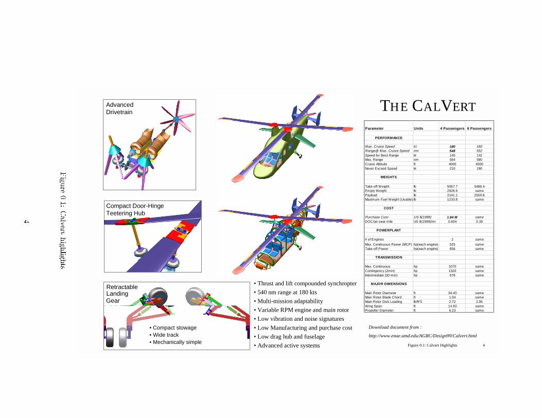
Parameter Units 4 Passengers 6 Passengers
PERFORMANCE
Max. Cruise Speed kt 180 160Range@ Max. Cruise Speed nm 548 552Speed for Best Range kt 140 142Max. Range nm 584 580Cruise Altitude ft 4000 4000Never Exceed Speed kt 210 190
WEIGHTS
Take-off W eight lb 5067.7 5486.4Empty Weight lb 2926.6 samePayload lb 2141.1 2559.8Maximum Fuel W eight (Usable) lb 1233.8 same
COST
Purchase Cost US $(1999) 1.84 M sameDOC/air-seat mile US $(1999)/mi 0.604 0.39
POWERPLANT
# of Engines 2 same
Max. Continuous Power (MCP) hp(each engine) 525 sameTake-off Power hp(each engine) 656 same
TRANSMISSION
Max. Continuous hp 1070 sameContingency (2min) hp 1320 sameIntermediate (30 min) hp 678 same
MAJOR DIMENSIONS
Main Rotor Diameter ft 34.43 sameMain Rotor Blade Chord ft 1.04 sameMain Rotor Disk Loading lb/ft 2̂ 2.72 2.95Wing Span ft 14.93 samePropeller Diameter ft 6.23 same
Compact Door-HingeTeetering Hub
AdvancedDrivetrain
Download document from :
http://www.enae.umd.edu/AGRC/Design99/Calvert.html
• Compact stowage• Wide track• Mechanically simple
RetractableLandingGear
THE CALVERT
• Thrust and lift compounded synchropter
• 540 nm range at 180 kts
• Multi-mission adaptability
• Variable RPM engine and main rotor
• Low vibration and noise signatures
• Low Manufacturing and purchase cost
• Low drag hub and fuselage
• Advanced active systems Figure 0.1: Calvert Highlights 4
Figu
re0.1:
Calvert
high
lights.
4

1 Introduction
This proposal presents the design of the Calvert { a helicopter designed from the outset to o�er
the best value to the customer. The Calvert takes its name from Charles Benedict Calvert, founder of
the Maryland Agricultural College (which later became the University of Maryland), and descendent
of George Calvert, the �rst Lord Baltimore and founder of the State of Maryland. Throughout the
design of the Calvert, careful attention has been paid to maximizing end-user value through perfor-
mance, economy, ease of use, and safety. It is believed that, by o�ering customers a large increase in
performance and capability with only a minor cost premium, the Calvert will be positioned to capture
a large part of the market to replace existing eets of older aircraft.
The Calvert was designed in response to a request for proposal (RFP) from AHS International and
Bell Helicopter as part of the 1999 AHS Student Design Competition. This RFP for a High-Speed
VSTOL Personal Transport speci�es a 4-6 seat aircraft that can cruise at 180 knots with a range of
540 nautical miles (dry tanks). These speci�cations require a substantial performance increase over
existing light helicopters with little or no increase in price. Most current light turbine helicopters, such
as the MD-500 and EC-120, are limited to a cruise speed of approximately 135 knots and mission range
of 350 nautical miles. Technical barriers to achieving a 180 knot cruise speed include compressibility
e�ects, retreating blade stall, poor cruise e�ciency and high levels of vibration and noise. The Calvert
is designed to overcome these limitations with little or no increase in cost over existing eets of 4-6
place helicopters. The RFP also requires the designers to pay special attention to producing a machine
that is easy and inexpensive to manufacture. In meeting all of these requirements, attention should be
paid to the target market { the general aviation marketplace. Speci�cally, the design should be focused
towards current owners and operators of aging light helicopters.
Ultimately, the secret to producing an item inexpensively is to engender enough customer demand
to merit the large production quantities necessary to realize substantial reductions in unit cost. The
bene�ts of mass production and large production runs are widely known.
Engineering a product for inexpensive mass production requires special attention to manufacturing
details. Engineering a product to generate a high demand requires attention to customer requirements.
Additionally, a successful product must o�er high quality in terms of ease of use along with traditional
metrics for performance, manufacturability and safety. Any vehicle designed to replace existing eets
should not impose signi�cant retraining requirements on the customer, and the ability to win new
customers can be strongly in uenced by the ease of learning to use and service the product.
These considerations have guided the design of the Calvert which not only ful�lls all the require-
ments of the RFP but also provides the mission exibility required to promote mass production of one
platform that ful�lls many missions.
5
2 Aircraft Configuration Trade Study
2.1 Candidate con�gurations
The requirements of the RFP can be met by a number of di�erent con�gurations. The most important
design requirements are the capability for high speed cruise (180 knots) and long range (540 nm). At
the very beginning of the design process a brainstorming session was conducted. Every member of
the design team was asked to propose a concept and justify his con�guration. At this stage, even the
most radical and technologically risky con�gurations were retained for further analysis. The goal was
to encourage creativity and original thinking. The following candidate con�gurations were proposed:
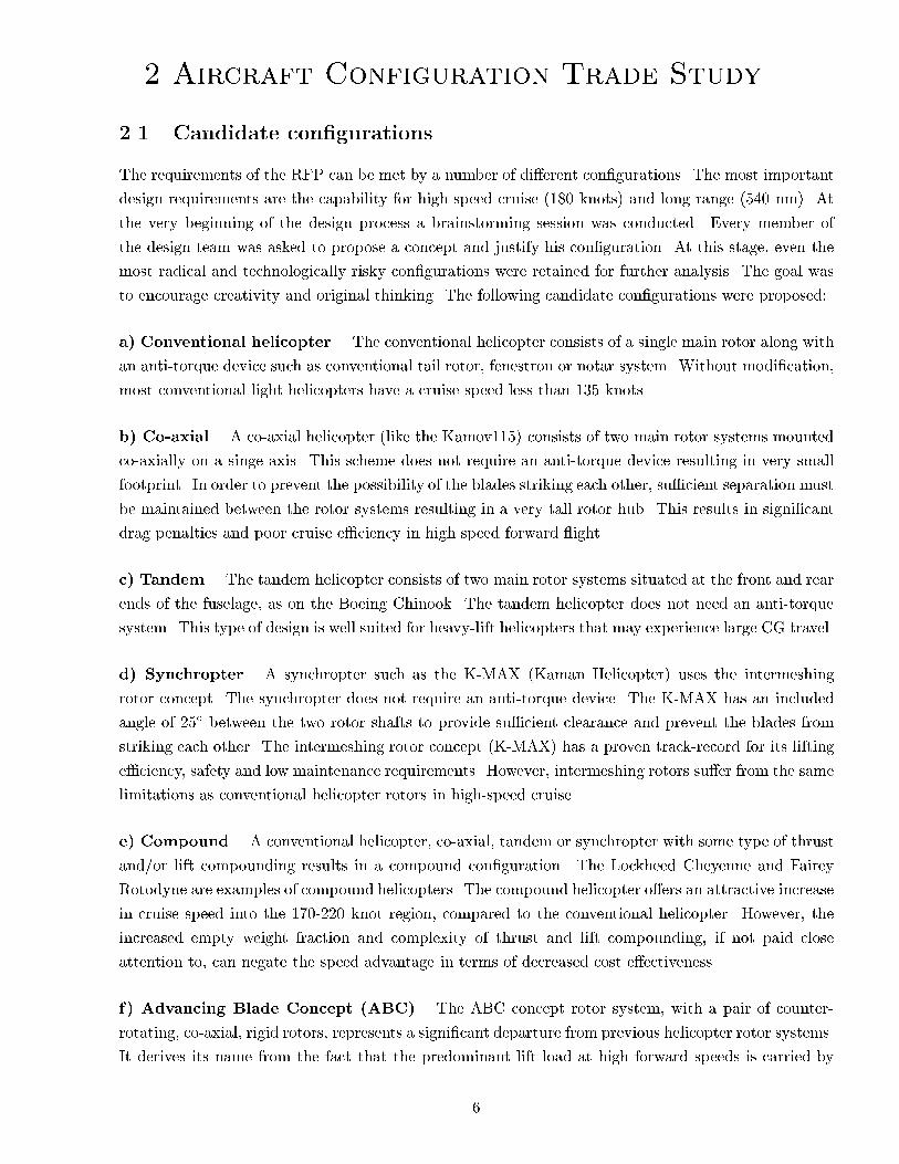
a) Conventional helicopter. The conventional helicopter consists of a single main rotor along with
an anti-torque device such as conventional tail rotor, fenestron or notar system. Without modi�cation,
most conventional light helicopters have a cruise speed less than 135 knots.
b) Co-axial. A co-axial helicopter (like the Kamov115) consists of two main rotor systems mounted
co-axially on a singe axis. This scheme does not require an anti-torque device resulting in very small
footprint. In order to prevent the possibility of the blades striking each other, su�cient separation must
be maintained between the rotor systems resulting in a very tall rotor hub. This results in signi�cant
drag penalties and poor cruise e�ciency in high speed forward ight.
c) Tandem. The tandem helicopter consists of two main rotor systems situated at the front and rear
ends of the fuselage, as on the Boeing Chinook. The tandem helicopter does not need an anti-torque
system. This type of design is well suited for heavy-lift helicopters that may experience large CG travel.
d) Synchropter. A synchropter such as the K-MAX (Kaman Helicopter) uses the intermeshing
rotor concept. The synchropter does not require an anti-torque device. The K-MAX has an included
angle of 25� between the two rotor shafts to provide su�cient clearance and prevent the blades from
striking each other. The intermeshing rotor concept (K-MAX) has a proven track-record for its lifting
e�ciency, safety and low maintenance requirements. However, intermeshing rotors su�er from the same
limitations as conventional helicopter rotors in high-speed cruise.
e) Compound. A conventional helicopter, co-axial, tandem or synchropter with some type of thrust
and/or lift compounding results in a compound con�guration. The Lockheed Cheyenne and Fairey
Rotodyne are examples of compound helicopters. The compound helicopter o�ers an attractive increase
in cruise speed into the 170-220 knot region, compared to the conventional helicopter. However, the
increased empty weight fraction and complexity of thrust and lift compounding, if not paid close
attention to, can negate the speed advantage in terms of decreased cost e�ectiveness.
f) Advancing Blade Concept (ABC). The ABC concept rotor system, with a pair of counter-
rotating, co-axial, rigid rotors, represents a signi�cant departure from previous helicopter rotor systems.
It derives its name from the fact that the predominant lift load at high forward speeds is carried by
6

the advancing blades on both sides of the aircraft. Since the retreating blades are not required to carry
a signi�cant fraction of the total lift load at forward speed, the speed and load factor limitations of
the conventional helicopter due to retreating blade stall are eliminated. The disadvantages of the ABC
rotor are high pro�le drag, hub drag, vibration, and power requirements.
g) Tilt rotor/wing. The tilt rotor and tilt wing concepts use a set of highly loaded main rotors as
propellers in cruise (Examples, V-22 and Bell Agusta-609). Compared to the conventional helicopter
the tilt rotor/tilt wing has much better cruise e�ciency at cruise speeds higher than 180 knots, at the
cost of poor weight e�ciency, autorotation, and e�cient low speed and hovering capabilities.
h) Stopped rotor. This high speed rotorcraft concept typically consists of a reaction-drive rotor that
is stopped after reaching conversion speed for high speed cruise ight [RB93]. The aircraft operates in
the helicopter mode in the 0 to 80 knot range. In the 80 to 170 knot range it operates as an autogyro
with propulsion provided by turbofans. Above 170 knots the rotors are stopped and locked to provide
lift as wings (see Figure 2.1(a)). Transition to the airplane mode is then complete.
(a) Stopped rotor. (b) Verticraft.
Figure 2.1: Two candidate aircraft con�gurations.
i) Verticraft. The Verticraft employs two counter-rotating circular disks. Four blades are connected
to each disk. The blades are used to generate lift in hover. In forward ight, the blades are completely
retracted into the circular disks. The disks together behave as a low aspect ratio circular wing with
propulsion being provided by a ducted fan or turbojet engine (see Figure 2.1(b)).
j) Cruisefan (Sadleir VTOL concept). The cruisefan utilizes the fan-in-wing concept. In oper-
ation, the lift fan draws air from the top of the wing, de ecting it into four primary lift ducts and
four smaller control ducts. The control ducts provide vertical lift, initial forward thrust and braking
control during hover and low speed forward ight. Inlets and exhausts of the fan-in-wing are closed
for high speed ight. A rear fan (conventional turbofan) provides thrust for high speed forward ight.
The estimated cruise speeds are over 400 knots. Development of this concept is being carried out by
Sadleir Corporation.
7
k) Autogyro. In cruise, the rotor of the autogyro is not powered directly. Under these conditions,
the power to drive the rotor and produce lift comes from the air ow through the rotor. Collective
pitch control is used to achieve \jump" take-o�s. This is accomplished by overspeeding the rotor on
the ground with the blades seat at a low pitch. Subsequently, the rotor is de-clutched, and the energy
stored in the rotor is used to lift the aircraft into the air through a sudden increase in blade pitch. An
autogyro is incapable of hovering and must autorotate to perform a vertical landing, both of which are
major limitations for VTOL civil transport operations.
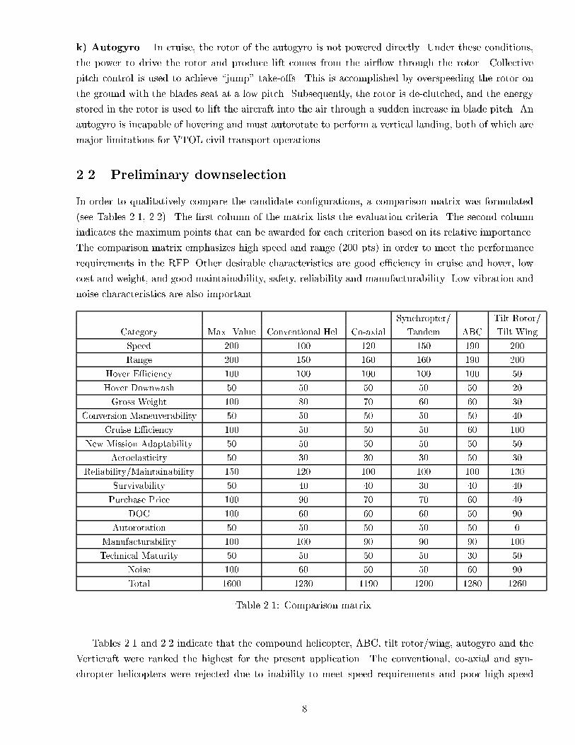
2.2 Preliminary downselection
In order to qualitatively compare the candidate con�gurations, a comparison matrix was formulated
(see Tables 2.1, 2.2). The �rst column of the matrix lists the evaluation criteria. The second column
indicates the maximum points that can be awarded for each criterion based on its relative importance.
The comparison matrix emphasizes high speed and range (200 pts) in order to meet the performance
requirements in the RFP. Other desirable characteristics are good e�ciency in cruise and hover, low
cost and weight, and good maintainability, safety, reliability and manufacturability. Low vibration and
noise characteristics are also important.
Synchropter/ Tilt Rotor/
Category Max. Value Conventional Hel. Co-axial Tandem ABC Tilt Wing
Speed 200 100 120 150 190 200
Range 200 150 160 160 190 200
Hover E�ciency 100 100 100 100 100 50
Hover Downwash 50 50 50 50 50 20
Gross Weight 100 80 70 60 60 30
Conversion Maneuverability 50 50 50 50 50 40
Cruise E�ciency 100 50 50 50 60 100
New Mission Adaptability 50 50 50 50 50 50
Aeroelasticity 50 30 30 30 50 30
Reliability/Maintainability 150 120 100 100 100 130
Survivability 50 40 40 30 40 40
Purchase Price 100 90 70 70 60 40
DOC 100 60 60 60 50 90
Autorotation 50 50 50 50 50 0
Manufacturability 100 100 90 90 90 100
Technical Maturity 50 50 50 50 30 50
Noise 100 60 50 50 60 90
Total 1600 1230 1190 1200 1280 1260
Table 2.1: Comparison matrix.
Tables 2.1 and 2.2 indicate that the compound helicopter, ABC, tilt rotor/wing, autogyro and the
Verticraft were ranked the highest for the present application. The conventional, co-axial and syn-
chropter helicopters were rejected due to inability to meet speed requirements and poor high speed
8

Category Max. Value Compound Stopped Autogyro Verticraft Cruise Fan
Speed 200 175 200 175 190 190
Range 200 175 200 175 190 190
Hover E�ciency 100 100 80 0 50 20
Hover Downwash 50 50 40 50 10 10
Gross Weight 100 60 50 100 80 60
Conversion Maneuverability 50 50 30 10 30 20
Cruise E�ciency 100 70 90 75 70 90
New Mission Adaptability 50 50 50 10 50 30
Aeroelasticity 50 30 20 30 40 50
Reliability/Maintainability 150 100 20 120 120 80
Survivability 50 30 20 30 40 45
Purchase Price 100 70 40 100 90 40
DOC 100 70 80 100 75 80
Autorotation 50 50 30 50 0 0
Manufacturability 100 90 50 100 80 70
Technical Maturity 50 40 0 40 20 10
Noise 100 50 70 100 90 50
Total 1600 1260 1070 1265 1240 1035
Table 2.2: Comparison matrix (continued).
cruise e�ciency. The tandem con�guration is more suited for large helicopters because su�cient hor-
izontal and vertical separation is needed between the two rotors. The cruise fan concept was rejected
due to poor hover e�ciency, large installed power (14349 HP) and substantial technical risks. The
stopped rotor was also eliminated. Lack of technical maturity leads to high development costs. Also,
for such a con�guration, the conversion from helicopter to �xed wing mode occurs at 170 knots [RB93].
Consequently, the stopped rotor is optimized for much higher cruise speeds (400-500 knots), and cannot
be considered a cost e�ective alternative to existing 4-6 seat helicopters.
Though the Verticraft appears very promising, it has numerous potential pitfalls. Preliminary
calculations using combined blade element momentum theory indicated high hover downwash and
moderate hover e�ciency. Inability to autorotate in case of engine failure presents serious safety
concerns. Also poor cruise e�ciency associated with the low aspect ratio circular wing is another
drawback. Due to these reasons the Verticraft was also rejected, however we feel that a more re�ned
analysis is necessary to do full justice to this unique and interesting concept.
The autogyro is the ideal vehicle to replace the automobile as the personal transport vehicle of
the future. It is fast, cheap, and relatively low tech. It requires low development and maintenance
costs. However, it cannot hover and this is a major limitation for the present design exercise. Also,
an autogyro is incapable of aborting a landing once committed. On an open �eld/runway this is not a
concern, but for operation in densely populated areas, the aircraft must demonstrate the capability to
abort a landing. In addition, the poor safety record and high accident rates of autogyros are a major
cause of concern (source: National Transportation Safety Board (NTSB) database, 1999). Possible
reasons for this statistic could be that autogyros are often own by amateur pilots with poor training
9

and a comparatively poor maintenance infrastructure. In conclusion, to replace existing eets of 4-6
seat helicopters, this design must demonstrate a wide range of mission capabilities, including adequate
hovering capability. Consequently, the autogyro is considered unsuitable for the present design study.
The ABC concept, with co-axial counter-rotating rigid rotors, is a prospect that can meet the
RFP speed and range requirements [dBF82]. Thrust compounding enables the fuselage and main rotor
system to be kept level in high speed forward ight. In hover, the use of two counter-rotating rotors
reduces the energy losses in the slipstream rotation. In 1973, Sikorsky ight tested the ABC rotor
system on the XH-59A. However, the rigid counter-rotating co-axial rotor system has its own set of
unique technical problems. A conventional rotor operates at very low angles of attack on the advancing
side. The ABC rotor, on the other hand, must generate all its lift on the advancing side and hence
operates at high angles of attack on the advancing side. This means that the pro�le power of an
ABC rotor is much greater than a conventional rotor. Additionally, the drag associated with the rigid
hub is also likely to be substantial. In fact, the XH-59A was equipped with two Pratt and Whitney
J60-P-3A turbojet engines for thrust augmentation in high speed forward ight. Each engine provided
3300 lb static thrust at sea level standard conditions. Also, the rigid rotor system used in the ABC
con�gurations typically results in high loads and vibration in high speed forward ight. For these
reasons, the ABC rotor will not be competitive compared to advanced compound and tilt rotor/wing
designs.
The Cheyenne, a compound helicopter with thrust and lift compounding, was built and ight tested
in the late 1960's. It ew at cruise speeds of over 200 knots. Dynamic problems associated with the
rigid rotor system (1/2-p hop) were subsequently solved in the 1970's. Such a vehicle presents no
signi�cant technological barriers and o�ers the promise of high speed VTOL capability with minimum
penalty in terms of cost and complexity. Recently, there has been renewed interest in the application
of compound helicopters as a means of extending the helicopter ight boundary for both civilian and
military applications [BB91],[JHB93].
The tilt rotor concept has been demonstrated by Bell-Boeing (V-22 Osprey). Recently Ishida [CS93]
has designed a tilt-wing aircraft for civil transport applications. The tilt rotor/wing concept o�ers some
distinct advantages and attractive features: superior vehicle lift to drag ratios compared to helicopters;
high speed and range capabilities; and low DOC per air-seat-mile compared to conventional helicopters.
However, low weight e�ciency and poor hovering capability can o�set these advantages, especially if
the mission range is less than 200-250 miles. The compound helicopter and tilt rotor/wing appear
to be the best solutions for the present RFP. The next section will describe the detailed trade study
between these two concepts.
2.3 Compound helicopter vs. tilt rotor
For this trade study, the candidate aircraft con�gurations are a thrust and lift compounded helicopter
and a tilt rotor. Considering that this is a �rst order analysis, the performance di�erences between
a tiltwing and a tiltrotor are expected to be negligible, and these two are considered as a single
concept. Furthermore, only a �xed diameter tiltrotor is considered. A variable diameter tiltrotor
o�ers the advantage of a reduced hover disk loading during VTOL and lower tip speed in forward
ight. However, these advantages are o�set by the added complexity and cost, and reduced e�ciency
10

associated with the non-optimal blade twist for the extended rotor blades in hover and reduced rotor
diameter for forward ight. Consequently, only a �xed diameter tiltrotor con�guration is investigated.
2.3.1 Engine, aerodynamic and weight models
There exist many methods for accurately calculating the performance characteristics of helicopters.
However, such methods can be used only when all the details of the helicopter con�guration are known.
During the preliminary design stage of a helicopter project, the con�guration is not known and it is
necessary to use approximate methods to proceed with the design. One such method is based on the
concept of vehicle lift/drag ratios [TNC99]. It is noteworthy that this idea was used in the mid-30's
by Hohenemser, who calculated the lift/drag ratio using the autorotation mode of an autogyro (rotor
draws zero power). Later, during the 50's the Russian scientist Dr. Braverman modi�ed and developed
the use of this concept. This methodology is now used in the Mil design bureau for conceptual design.
For the present study, forward ight for both compound helicopter and tilt rotor is modeled using
the concept of cruise lift/drag ratios. Hover performance is analyzed via momentum theory, tak-
ing into account �gure of merit, vertical drag and transmission e�ciency correction factors. Take-o�
weight is calculated using assumed weight e�ciencies. Take-o� weight will include the payload (pas-
sengers+baggage) and estimated fuel. These empirical formulae are obtained from curve �ts to weight
trends of existing VTOL aircraft and are de�ned separately for conventional helicopters and a wing-
borne con�guration [TNC99]. This �rst order model ignores two important features: �rst, the empty
weight fraction is assumed to be a function of only the take-o� weight, whereas it is also signi�cantly
in uenced by the disk loading; second, the empirical cruise performance based on lift/drag ratios fails
to capture the e�ects of the detailed rotor parameters (planform, tip geometry, advanced airfoils) and
wing con�guration. These e�ects have been modeled in Chapter 6. The present study uses the engine
model speci�ed in the RFP.
2.3.2 Economic model and comparison indices
The helicopter cost analysis uses the cost model speci�ed in the RFP. The aircraft cost e�ectiveness will
be evaluated in terms of four parameters: direct operating cost per air-seat-mile (DOC/asm), initial
cost (IC), life cycle cost (LCC) and rentability index (RI).
DOC Calculation Description
Purchase Price RFP cost model
Fuel Cost 1.5 $/gallon (Jet A fuel)
Maintenance [Ols93] 0.067/fh/lb (per ight hour per lb empty weight)
Residual Value 10% (with an aircraft life of 10000 ight hours)
Financing [Sco96] 8% per year
Insurance [Sco96], [Ols93] Compound Helicopter: 5.5% per year, Tilt Rotor : 6% per year
Crew Cost $62 per ight per crew member
Table 2.3: Cost analysis summary.
11

The DOC/asm (which includes depreciation, �nancing, insurance, maintenance, fuel cost, and pilot
salary) is a measure of the expenses incurred by the operator per air-seat-mile and does not account for
the value of the passenger's time. Scott [Sco96] reports an average maintenance cost of $ 0.067/ ight-
hour(fh)/pound-empty(lb) for a 40-seat, 600 nm tiltrotor, compared to $ 0.063/fh/lb (empty) for a
40-seat, 400 nm helicopter. These values correlate well with the $0.067/fh/lb (empty) quoted by Olson
[Ols93]. For the present trade study, a maintenance cost of $ 0.067/fh/lb (empty) will be used to
calculate the DOC/asm for both the helicopter and the tilt rotor. The life cycle cost calculates the
total cost of the aircraft over its lifetime (includes IC as well as DOC/asm):
LCC = IC + (DOC=asm)� (#seats)� (mission distance)� (total # flights in lifetime)
(2.1)
The rentability index (RI) is a cost measure that is de�ned to quantify the premium a passenger is
prepared to pay to shorten the e�ective ight time by a certain percentage. Gmelin et al. [GJP+89]
indicated that the customer is willing to pay 30% more to double the e�ective speed and proposed the
following de�nition:
RI =V 0:4b
DOC=asm(2.2)
where Vb is the e�ective ight speed, based on the passengers total ight time from boarding to
disembarking. The higher the rentability, the more cost e�ective the aircraft. The best design is one
that optimizes the cost drivers identi�ed above: maximizes the cruise speed (RI) and minimizes the
cost (LCC, DOC/asm and IC).
2.3.3 Mission pro�le
Helicopters can be designed for numerous types of missions (conventional civil transport, search and
rescue, endurance etc). Our interpretation of the RFP is that the primary mission is long range civil
transport. The assumed primary mission pro�le is shown in Figure 2.2. The nominal and maximum
cruise altitude for the compound helicopter is taken as 4000 ft and 8000 ft respectively. The low level
cruise o�ers some distinct advantages. First, tra�c con icts with faster �xed wing commercial air
tra�c are avoided. Second, the need for aircraft pressurization is eliminated, resulting in a weight and
power reduction. The main disadvantage of the low level cruise is that ight operations will be a�ected
if bad weather extends above 8000 ft. The en-route climb rate is limited by the FAR to 1250 ft/min,
because the cabin is unpressurized. In contrast, the tilt rotor has to climb to a cruise altitude of 18000
ft to achieve e�cient ight at the maximum lift to drag ratio. However, the RFP speci�es a maximum
cruise altitude of 10000 ft. This will adversely a�ect the lift/drag ratio of the tiltrotor. For the present
study, a cruise altitude of 10000 ft is selected for the tiltrotor.
2.3.4 Trade study methodology
The owchart for the trade o� study is shown in Figure 2.3. The known or �xed inputs are the mission
pro�le, range (540 nm) and number of passengers (four). Since this is a personal transport helicopter
the passengers also include the pilot. The cruise speed for the compound helicopter is 180 knots (as
12

Taxi at idle(5 min)
Climb
Compound: 180 knots cruise at 4000 ft, ISA
Descent
Hover OGEISA (1 min)
Taxi (5 min)
Tilt Rotor: 250 knots cruise at 10,000 ft, ISA
Figure 2.2: Conventional civil transport mission pro�le.
required by the RFP) and the corresponding value for the tiltrotor is 250 knots (similar to BB-609).
Conventional light helicopters have a lift/drag ratio of 4.2 [TNC99] at 130 knots and weight e�ciencies
around 0.46 [TNC99]. The weight e�ciency (Equation 5.2) of an aircraft is de�ned as the ratio of the
total payload (including passengers, crew and fuel) to the gross weight. A compound helicopter has a
higher empty weight fraction than a conventional helicopter. Therefore, a weight e�ciency of 0.42 is
selected for the compound. Also, the cruise lift/drag ratio of a compound helicopter at 180 knots is
expected to be lower than a conventional helicopter cruising at 130 knots. Therefore, a cruise lift/drag
ratio of 3.7 is selected for the compound helicopter. The tilt rotor is assumed to have a lift/drag ratio
of 8.5 [TNC99] and weight e�ciency of 0.35 (similar to BB-609). Based on the lift/drag ratio, weight
e�ciency, and disk loading, the aircraft gross weight is estimated. The gross weight is used to size the
rotor and powerplant and estimate the fuel and component weights. This process is repeated until the
initial gross weight estimate and the calculated all up mass converge. Subsequently, the initial cost,
DOC/asm, life cycle cost and rentability index are calculated for the compound helicopter and tilt
rotor. This process is repeated for di�erent values of disk loading.
2.3.5 Trade study results
To check the numerical accuracy of the simulation, the code was validated for the MD-500E and the
BB-609. For the MD-500E, a lift/drag ratio of 4.2 at a cruise speed of 134 knots was selected [TNC99].
For the BB-609, a lift/drag ratio of 8.5 at a cruise speed of 257 knots was chosen [TNC99]. Table 2.3
shows a comparison of the results obtained from the present method with the published values for the
MD-500E and the BB-609.
Table 2.4 indicates that the preliminary �rst order analysis shows good agreement with existing
VTOL con�gurations. The actual purchase price of the MD-500E ($ 0.67 million) is much lower than
the value given in the simulation ($ 1.7 million). This is because the simulation assumes a production
quantity of 300 aircraft and a production rate of 60 per year as speci�ed in the RFP. However, the MD-
500 has been produced in much larger numbers, and hence has a lower purchase price. Having developed
su�cient con�dence in the simulation, we now apply the algorithm to the compound helicopter and
the tilt rotor. In this preliminary study, the disk loading was selected as the primary input parameter.
Figures 2.4-2.6 show the take-o� weight, fuel weight, nominal engine power, IC, DOC/asm and RI as
a function of disk loading.
13

Weight EfficiencyDisk Loading
Cruise Speed, L/D ratioINPUTS: CH or TR
All-up Mass
Mission AnalysisSize Rotor, powerplantEstimate fuel weightEmpty weight estimation
Initial Weight
Cost Analysis, Initial Cost,DOC/asm, Life cycle Cost,Rentability Index
Iterate tillconvergence
Known QuantitiesMission Profile, altitude, Range (540 nm), Passengers: 4 (incl. Pilot)
Figure 2.3: Trade study methodology.
Figure 2.4 indicates that the take-o�-mass (1918 kg) and fuel weight (420.9 kg) of the compound
helicopter is nearly constant in the 10 to 60 kg/m2 disk loading range. The tilt rotor on the other hand
shows a monotonically increasing trend for take-o� weight and fuel weight in the 30-110 kg/m2 disk
loading range. For a disk loading of 50 kg/m2 the tilt rotor and compound helicopters have the same
gross take-o� weight. Figure 2.4 also indicates that the tilt rotor needs to carry less fuel compared
to the compound con�guration due to its superior cruise lift/drag ratio. Figure 2.5 shows that the
compound helicopter has greater installed power compared to the tilt rotor for disk loadings below
50 kg/m2. Above 50 kg/m2, the tilt rotor has greater installed power requirements. Figure 2.5 also
shows that the purchase price of the compound helicopter is considerably less than that of the tilt
rotor over a wide range of disk loadings. Figure 2.6 indicates that the compound helicopter has a
lower DOC/asm compared to the tilt rotor. This is because the lower purchase price and empty weight
of the compound helicopter o�sets the lower fuel consumption of the tilt rotor, resulting in reduced
operating costs. Figure 2.6 also shows that the rentability index has a cross-over point at a disk loading
of 50 kg/m2. For disk loadings below 50 kg/m2 the tilt rotor has a superior rentability. This trend is
reversed above 50 kg/m2.
For the cost comparison, a disk loading of 30 kg/m2 is used for the compound helicopter. This is
representative of existing light helicopters such as the MD 500E and the EC120. For the tilt rotor, lower
disk loadings improve the performance (Figures 2.4-2.6). As a compromise between low disk loading
and reasonable rotor diameter, a disk loading of 50 kg/m2 was selected for the tilt rotor. The estimated
empty weight, fuel weight and initial cost from Figures 2.4-2.6 is used to calculate the Direct Operating
Cost per air-seat-mile (DOC/asm) and Life Cycle Cost (LCC). The DOC/asm includes both Cash DOC
(fuel, lubricants, maintenance and ight crew salary) as well as Ownership DOC (depreciation, hull
insurance and �nancing). The life cycle cost is calculated using equation 2.1 (section 2.3.2). Table
14

0 20 40 60 80 1001400
1500
1600
1700
1800
1900
2000
2100
2200
Disk Loading (Kg/m2)
Gro
ss W
eig
ht
(Kg
)
Compound HelicopterTilt Rotor
(a) Take-o� mass vs. disk loading.
0 20 40 60 80 1000
100
200
300
400
500
Fu
el W
eig
ht
(Kg
)
Disk Loading (Kg/m2)
Compound HelicopterTilt Rotor
(b) Fuel weight vs. disk loading.
Figure 2.4: Take-o� mass and fuel weight vs. disk loading.
0 20 40 60 80 1000
200
400
600
800
1000
1200
1400
1600
Insta
lled
Po
we
r (H
P)
Disk Loading (Kg/m2)
Compound HelicopterTilt Rotor
(a) Installed power vs. disk loading.
0 20 40 60 80 1000
0.5
1
1.5
2
2.5
3
3.5
4
4.5
Disk Loading (Kg/m2)
Pu
rch
ace
Price
($
Mill
ion
)
Compound HelicopterTilt Rotor
(b) Purchase price vs. disk loading.
Figure 2.5: Installed power and purchase price vs. disk loading.
15

Property Units MD-500E BB-609
Simulation Actual Simulation Actual
Gross Weight lb (kg) 3219 (1460) 3003 (1362) 15611 (7081) 16032 (7272)
Fuel Weight lb (kg) 410.83 (186.35) 396.99 (180.07) 2714 (1231) 3135 (1422)
Installed Power hp (kW) 457.84 (341.41) 420 (313) 3905 (2912) 3693 (2754)
Main Rotor Diameter ft (m) 27.92 (8.51) 26.38 (8.04) 25.66 (7.82) 25.98 (7.92)
Main Rotor Chord ft (m) 0.486 (0.148) 0.568 (0.173) { {
Tail Rotor Diameter ft (m) 5.05 (1.54) 4.56 (1.39) { {
Tail Rotor Chord ft (m) 0.492 (0.15) 0.439 (0.134) { {
Cost US$ 1.7M 0.67M (1993 $) 9.9M 8-10M
Table 2.4: Code validation.
2.5 gives the performance summary for the compound helicopter and the tilt rotor. The performance
summary lists the disk loading, cruise speed, travel time, rotor diameter, take-o� mass, fuel capacity,
nominal power, initial cost, DOC/asm, life cycle cost and the rentability index.
Description Units Compound Helicopter Tilt Rotor
Disk Loading lb/ft2 (kg/m2) 5.77 (30) 9.62 (50)
Cruise Speed knots 180 250
Travel Time hours 3 2.15
Rotor Diameter ft (m) 29.59 (9.02) 15.06 (4.95)
Take-o� weight lb (kg) 4229.22 (1918.34) 4245.38 (1925.67)
Fuel Weight lb (kg) 927.9 (420.9) 626.88 (284.35)
Nominal Power hp (kW) 886.45 (661.03) 882.24 (657.89)
Initial Cost (Purchase Price) US$ 2.06M 3.48M
DOC/asm US$ 0.6385 0.729
LCC US$ 7.31M 11.76M
Rentability Index - 15.75 15.64
Table 2.5: Trade study performance summary.
2.3.6 Downselection
Based on the performance summary in Table 2.5, the following conclusions are made:
1) For the same payload, the compound helicopter and tilt rotor have nearly the same gross weight
and installed power. However, with blades folded, the compound helicopter will require less space than
the tilt rotor. The larger apron footprint directly impacts the cost of vertiport development, especially
in downtown areas.
2) The compound helicopter has a lower purchase price ($2.06 million) compared to the tilt rotor
($3.48 Million). The RFP stipulates that the purchase price must be comparable to existing eets of
4-6 seat helicopters. Clearly, the tilt rotor is a very expensive solution, and does not ful�ll the stringent
16

0 20 40 60 80 1000
0.2
0.4
0.6
0.8
1
DO
C/a
sm
( $
)
Disk Loading (Kg/m2)
Compound HelicopterTilt Rotor
(a) DOC/asm vs. disk loading.
0 20 40 60 80 10010
11
12
13
14
15
16
17
18
Disk Loading (Kg/m2)
Re
nta
bili
ty I
nd
ex
Compound HelicopterTilt Rotor
(b) Rentability index vs. disk loading.
Figure 2.6: DOC/asm and rentability index vs. disk loading.
RFP cost requirements.
3) The compound helicopter has a lower DOC/asm ($0.63) as compared to the tilt rotor ($0.72).
Note that these numbers are much higher than the typical DOC/asm for conventional �xed wing
turboprops ($0.15).
4) The life cycle cost for the compound helicopter is $7.31 million as compared to $11.76 million
for the tilt rotor. Ultimately, cost is driven by production quantity. Therefore aircraft that have good
mission adaptability characteristics will be sold in larger quantities and hence will be cheaper. The
compound helicopter is a very versatile aircraft. It has excellent hovering capability coupled with high
speed cruise capability. Hence, it can have numerous applications (search and rescue, long range civil
transport, surveillance etc). The tilt rotor, on the other hand, has poor hovering e�ciency and is much
more restricted in its potential applications. Thus the compound helicopter is the more cost-e�ective
solution.
5) The rentability index for the compound helicopter (15.75) is marginally greater than the tilt
rotor(15.64). The primary reason for this is the cruise speed of 250 knots used for the tilt rotor. For
a tilt rotor with a cruise speed of 350 knots the present analysis gives a rentability index of 27.27 and
DOC/asm of $0.47, thus greatly improving its marketability. However, such a high speed tilt rotor
would have to cruise at 18000 ft where its cruise e�ciency would be the greatest. Since the RFP
stipulates that the maximum cruise altitude is 10000 ft, a cruise speed of 250 knots is more realistic.
In conclusion, within the constraints of the RFP, the tilt rotor does not provide a superior rentability
index, in spite of its higher cruise speed.
6) FAA certi�cation policies exist for helicopters along with pilot training regulations, safety proce-
dures and other associated infrastructure. On the other hand, no FAR exists for tilt rotors. Therefore,
the compound helicopter is more suitable as a personal transport VTOL aircraft at the present time.
17

7) The main disadvantage of the compound helicopter is that it takes 3 hours to complete a 540
nm trip compared to 2 hours and 9 minutes for the tilt rotor. However, the trade study shows that
the reduced passenger ight time for the tilt rotor if o�set by the reduced cost and superior mission
exibility of the compound helicopter.
Thus the compound helicopter is the best solution to meet the RFP.
2.4 Compound con�guration trade studies
Numerous design decisions must be made before the compound helicopter layout can be frozen. Central
to the concept of a compound helicopter is the notion of thrust and lift o�-loading of the main rotor.
The thrust o�-loading enables the fuselage and the rotor disk to be kept nearly level in high speed
forward ight, improving the cruise lift/drag ratio. Lift o�-loading is bene�cial if the rotor is operating
close to the stall boundary (Since the rotor lift requirements are reduced, the classical retreating blade
stall envelope can be expanded). This section will deal with various design trades associated with
compound helicopters.
2.4.1 Thrust compounding mechanism
The objective of this section is to select an appropriate thrust augmentation mechanism. In chapter
6 we show that, for peak e�ciency, 80% rotor thrust o�-loading is necessary. This corresponds to a
static thrust capacity of 660 lbs at 4000 ft, ISA. For the present study, the following thrust generation
mechanisms were considered: jet propulsion, variable cycle engine, ducted fan, and the propeller.
1) Jet propulsion. Williams International, in collaboration with NASA Lewis, is developing a high
bypass turbofan (FJX-2) for general aviation. This engine can provide up to 700 lbs of thrust and weighs
100 lbs. The engine 41 inches long and 14.5 inches in diameter. For our application, the moderate
cruise speed (180 knots) and low cruise altitudes (4000 ft) will adversely a�ect the fuel e�ciency of the
FJX-2. Thus jet propulsion is not a cost e�ective solution to the thrust augmentation problem.
2) Variable cycle engine. Westland Helicopters and Rolls-Royce [BB91], [JHB93] have proposed
modifying the RTM322 engines with variable area exhaust nozzles. With the exhaust nozzle in the
fully open position, the engine will behave as a conventional turboshaft engine but as the nozzle is
progressively closed, back pressure increases and there is a transfer of energy from shaft power to jet
thrust. This results in a convertible, variable cycle powerplant that produces high shaft power but very
little thrust at one extreme or a high proportion of thrust with some shaft power at the other. The
engine may be operated smoothly anywhere between these two extremes.
The variable cycle engine is a simple and readily available option for using a turboshaft engine in
a dual mode (shaft power and thrust generation). However this type of design results in a reduction
in cruise e�ciency and hence is not necessarily the best solution in a transport role [JHB93]. This is
particularly true in this case because of the high thrust requirements (660 lbs at 4000 ft, ISA). In fact,
Westland's development of the variable cycle engine is directed towards military helicopters (Lynx)
where minimizing the DOC/air-seat-mile is not the primary goal. For these reasons, the variable cycle
engine was rejected as a possible thrust augmentation mechanism.
18

3) Ducted fan. This scheme consists of a fan enclosed inside a shroud. The advantage of the ducted
fan is that it shields a thrusting propeller from the wake of the main rotor. The ducted fan also results
in a smaller fan diameter compared to a conventional propeller. The primary disadvantage of this
system is large drag on the duct (shroud) in high speed forward ight (180 knots). For these reasons,
the ducted fan was also considered unsuitable for this project.
4) Propeller. The conventional propeller is used on the Cheyenne for thrust augmentation. The
propeller is the most e�cient solution for generating large thrust (660 lbs) at moderate forward speeds
(180 knots). Also, considerable information/test data is available on propeller design. For these
reasons, the propeller was selected for the thrust compounding mechanism. An alternative to the
conventional propeller is a contra-rotating propeller system which will reduce the swirl velocity in the
wake, improving the propeller e�ciency. Since limited design data is available on such systems, and
due to the increase in the complexity of the transmission, contra-rotating propellers were rejected in
favor of a conventional propeller.
2.4.2 High wing vs. low wing
In chapter 6 we show that the optimum lift o�oading (Wing Lift at CruiseGross Weight
) is 40%. This results in a
wing cruise lift requirement of 2025 lbs with associated wing dimensions of 14.93 ft span, 3.32 ft root
chord and 1.66 ft tip chord. The wing can either be a high wing (located above the passenger cabin) or
a low wing (located below the passenger cabin). The advantages of a low wing are reduced wing-rotor
interactional losses in ground e�ect and lower interference drag between the rotor and the wing in
cruise.
However, wake measurements [Bha98] have shown that the induced velocity Out of Ground E�ect
(OGE) below the rotor disk asymptotes to a value of 1.8 times that at the plane of the rotor disk at
a distance of about 0.2 times the rotor radius. Since both the high and low wing con�gurations were
likely to be separated from the rotor disk by more than 0.2R, the in uence of the rotor in ow on the
wing for both con�gurations out of ground e�ect are approximately equal. For normal operating HOGE
and cruise conditions, the aerodynamic considerations therefore were not overwhelmingly di�erent for
either con�guration.
The primary disadvantage of the low wing is the possibility of the wings striking the ground during
landing and take-o�. The low wing also results in ground interference, especially during cargo/passenger
loading and unloading. In contrast the high wing gives su�cient ground clearance margins. A high
wing can be given an anhedral angle to eliminate the risk of the blades striking the wings and to
improve the aircraft lateral-directional stability characteristics. For these reasons, a high wing was
selected for the present design.
2.4.3 Single main rotor vs. dual main rotors
In this section the relative merits of single main rotor and dual main rotor compound con�gurations
are compared. The rear propeller and high wing are common to both types of con�gurations. Figures
2.7(a) and 2.7(b) show the classical single main rotor with tail rotor (SMR-TR) and single main rotor
19

(a) SMR-TR con�guration. (b) SMR-FAN con�guration.
(c) Coaxial-ABC con�guration. (d) Synchropter con�guration.
Figure 2.7: Most competitive con�gurations.
with fan-in-�n (SMR-FAN) con�gurations, while Figures 2.7(c) and 2.7(d) depict the coaxial-ABC and
synchropter dual main rotor con�gurations.
A detailed drag estimation was carried out for each of the above concepts using the procedure
outlined in Chapter 6. The equivalent at plate areas for the SMR-TR, SMR-FAN, coaxial-ABC,
and synchropter con�gurations are listed in Table 2.6. These equivalent at plate areas include the
fuselage, tail boom, hub, landing gear, tail rotor/fenestron drag and the wing drag. The rotor blade
drag is not included in the at plate area calculation. The fuselage frontal area is kept the same for
all the con�gurations, while the fuselage length is reduced for the more compact coaxial-ABC and
synchropter con�gurations. Table 2.6 shows that the SMR-TR has the least at-plate area and the
SMR-FAN, synchropter and coaxial-ABC con�gurations have progressively increasing drag. In the
dual main rotor designs the two hubs account for over 50% of the total drag. However, the absence of
the tail rotor and reduced fuselage length (less wetted area) compensates for the drag penalty of the
extra hub.
Con�guration Flat Plate Area
m2
SMR-TR 0.887
SMR-FAN 0.896
Synchropter 0.943
Coaxial-ABC 0.97
Table 2.6: Equivalent at plate areas of all non lifting surfaces and wing.
A major disadvantage of the SMR-TR and SMR-FAN designs is that the presence of the large
20

propeller (1.9 m diameter) and the tail rotor/fenestron results in a long and heavy tail boom. It is
particularly di�cult to satisfy the CG balancing requirements on such con�gurations. The Cheyenne
had guns and armaments mounted near the cockpit which helped to bring the vehicle CG close to
the main rotor. For civil transport aircraft, this is not possible. In contrast, the coaxial-ABC and
synchropter compounds o�er more compact and elegant solutions. The ABC rotor generates all its
lift on the advancing side and hence operates at high angles of attack on the advancing side. Since
the incident velocity is also the highest on the advancing side, this results in large pro�le losses. Thus
the drag penalty on a coaxial-ABC rotor is likely to be higher than a synchropter rotor. This coupled
with the fact that the e�ective at plate area (non-lifting surfaces and wing) for the synchropter is
lower than the coaxial-ABC (Table 2.6), indicates that the synchropter compound has a better cruise
e�ciency than the coaxial-ABC compound. For these reasons, the synchropter compound was selected.
2.4.4 Landing gear
For the landing gear there are several possibilities : skid, nose-wheeled tricycle and tail-wheeled tricycle.
The skid and wheeled tricycle con�gurations can be either �xed or retractable. The Calvert has a
large propeller (diameter 1.9 m(6.23 ft)), located at the rear end of the tail boom. Consequently, a tail
wheeled tricycle con�guration will result in low ground clearance for the propeller blades. Therefore the
tail-wheeled tricycle con�guration was rejected. Among the �xed con�gurations, the �xed nose wheel
tricycle con�guration has higher drag and cost compared to the �xed skid con�guration. Therefore
the �xed nose-wheel tricycle con�guration was rejected. Among the retractable con�gurations, the
retractable nose-wheel tricycle design provides greater exibility for ground operations (taxiing, turning
etc) compared to the retractable skid. Therefore the �xed skid and retractable nose-wheel tricycle
con�gurations were downselected for further analysis.
Parameter Units Fixed-Skid Retractable-Wheeled
Flat Plate Area (m2) (0.95) (0.85)
Gross Weight lb (kg) 5322.2 (2414.1) 5283.4 (2396.5)
Fuel Weight lb (kg) 1216.1 (551.6) 1128 (512)
Installed Power hp (kW) 1588 (1184) 1475 (1100)
Purchase Price US$ 2.08M 2.07M
Table 2.7: Skid vs. retractable landing gear.
The weights of the landing gear were estimated using the RTL formulae [SS83] described in chapter
5. The retractable nose-wheel tricycle landing gear (93 kg) weighs approximately three times the �xed
skid landing gear (34 kg). However, the drag analysis described in the previous section indicates that the
retractable landing gear results in a 0.1 square meter reduction in the equivalent at plate area. Table
2.7 compares a 6-bladed synchropter (two three bladed hubs) with �xed-skid and retractable-wheeled
landing gears. Table 2.7 shows that the retractable landing gear results in a 39.6 kg saving in fuel
consumption per ight (This is a re ection of the lower at plate area of the retractable con�guration).
Over the life time of the helicopter, the reduced fuel consumption amounts to savings of $0.08 million.
The retractable con�guration also requires lower cruise power and hence lower transmission and engine
21
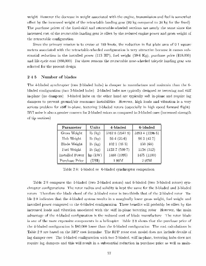
weight. However the decrease in weight associated with the engine, transmission and fuel is somewhat
o�set by the increased weight of the retractable landing gear (93 kg compared to 34 kg for the �xed).
The purchase prices of the �xed-skid and retractable-wheeled versions are nearly the same since the
increased cost of the retractable landing gear is o�set by the reduced engine power and gross weight of
the retractable con�guration.
Since the primary mission is to cruise at 180 knots, the reduction in at plate area of 0.1 square
meters associated with the retractable-wheeled con�guration is very attractive because it causes sub-
stantial reduction in the installed power (113 HP), fuel weight (39.6 Kg), purchase price ($10,000)
and life cycle cost ($80,000). For these reasons the retractable nose-wheeled tricycle landing gear was
selected for the present design.
2.4.5 Number of blades
The 4-bladed synchropter (two 2-bladed hubs) is cheaper to manufacture and maintain than the 6-
bladed con�guration (two 3-bladed hubs). 2-bladed hubs are typically designed as teetering and sti�
in-plane (no dampers). 3-bladed hubs on the other hand are typically soft in-plane and require lag
dampers to prevent ground/air resonance instabilities. However, high loads and vibration is a very
serious problem for sti� in-plane, teetering 2-bladed rotors (especially in high speed forward ight).
BVI noise is also a greater concern for 2-bladed rotors as compared to 3-bladed ones (increased strength
of tip vortices).
Parameter Units 4-bladed 6-bladed
Gross Weight lb (kg) 5162.8 (2341.8) 5283.4 (2396.5)
Hub Weight lb (kg) 56.4 (25.6) 96.3 (43.7)
Blade Weight lb (kg) 102.1 (46.3) 150 (68)
Fuel Weight lb (kg) 1123.7 (509.7) 1128 (512)
Installed Power hp (kW) 1468 (1095) 1475 (1100)
Purchase Price (US$) 1.99M 2.07M
Table 2.8: 4-bladed vs. 6-bladed synchropter comparison.
Table 2.8 compares the 4-bladed (two 2-bladed rotors) and 6-bladed (two 3-bladed rotors) syn-
chropter con�gurations. The rotor radius and solidity is kept the same for the 2-bladed and 3-bladed
rotors. Therefore the blade chord of the 3-bladed rotor is two-thirds that of the 2-bladed rotor. Ta-
ble 2.8 indicates that the 4-bladed system results in a marginally lower gross weight, fuel weight and
installed power compared to the 6-bladed con�guration. These bene�ts will probably be o�set by the
increased loads and vibration associated with the sti� in-plane teetering rotor. However, the main
advantage of the 4-bladed con�guration is the reduced cost of blade manufacture. The rotor blade
is one of the more expensive components in a helicopter. Table 2.8 shows that the purchase price of
the 4-bladed con�guration is $80,000 lower than the 6-bladed con�guration. The cost calculations in
Table 2.8 are based on the RFP cost formulae. The RFP rotor cost model does not include details of
lag damper cost. The 4-bladed con�guration with two 2-bladed, sti� in-plane, teetering hubs does not
require lag dampers and this will result in a substantial reduction in purchase price as well as main-
22

tenance costs. Additionally, the 4-bladed intermeshing rotor allows for improved safety clearances and
reduced possibility of the blades striking each other. Problems of high loads and vibration associated
with the sti� in-plane rotor system are mitigated due to thrust and lift o�oading of the main rotor in
high speed forward ight. For these reasons, the 4-bladed synchropter con�guration with two 2-bladed
sti� in-plane teetering hubs is the best compromise in terms of cost, complexity, safety, performance,
maintainability and aesthetics.
2.5 Conclusion
This chapter has presented a large number of design choices. Initially ten concepts were considered:
conventional helicopter, tandem/synchropter, co-axial, compound, ABC, tilt rotor/wing, stopped rotor,
cruise fan, Verticraft and autogyro. A comparison matrix was prepared to downselect two concepts
for detailed analysis (the thrust and lift compounded helicopter and the tilt rotor). The trade-o�
study revealed that the compound helicopter is the more cost-e�ective solution to the present RFP.
The maximum cruise altitude limitation of 10,000 ft coupled with the stringent RFP cost requirements
(purchase price should be comparable to existing eets of 4-6 seat helicopters) severely limit the tilt
rotor. In contrast the compound helicopter o�ers the promise of improved performance (180 knots,
540 nm) with minimum increase in cost and complexity over existing helicopter designs.
Various options were considered for the thrust compounding mechanism (jet propulsion, variable
cycle engine, ducted fan, contra rotating propeller and conventional propeller). It was determined
that the conventional propeller is the most e�cient mechanism for generating the required thrust at
moderate cruise speeds (180 knots). For the wing design, the high wing was selected over the low wing
(The high wing gives improved ground clearances).
A comparison of single main rotor and dual main rotor compound con�gurations revealed that the
single main rotor designs are \tail heavy" and not ideally suited to civil transport applications (CG
balancing problems). Dual main rotor con�gurations such as the co-axial ABC and the synchropter
compounds o�er more compact con�gurations. However, the large pro�le power of the ABC rotor
reduces its cost e�ectiveness. Drag estimates indicate that the increased drag penalty associated with
two rotor hubs (synchropter) is partially o�set by the absence of tail rotor blades, tail rotor hub
and reduced fuselage length. However, the synchropter hubs and transmission deck must be carefully
designed (with hub caps, fairings etc) to minimize the drag penalty. The synchropter compound
emerged as the best compromise for meeting the RFP performance and cost targets.
The retractable-wheeled landing gear gives signi�cant improvement in cruise e�ciency at 180 knots
compared to a �xed-skid landing gear. Therefore, a retractable nose-wheel tricycle landing gear was
selected. Also, a 4-bladed synchropter (two 2-bladed hubs) signi�cantly reduces manufacturing cost
as compared to a 6-bladed con�guration (two 3-bladed hubs). Therefore, a 4-bladed con�guration
was selected. All subsequent chapters will describe the detailed design of the 4-bladed compound
synchropter.
23

3 Aircraft Level Description
The Calvert is a thrust and lift compounded synchropter. It utilizes a pair of intermeshing rotors
to provide thrust and control in low speed ight. At higher speeds, the main rotors are thrust and lift
o�-loaded. Figure 3.1 is a four-view of the Calvert. Table 3.1 identi�es key parameters and capabilities
of the Calvert. These speci�cations indicate that the Calvert is designed to ful�ll the RFP requirements
(180 knots, 540 nm) with 4 passengers. However, with 6 passengers (maximum seating capacity), the
Calvert can y 552 nm at 160 knots cruise speed. The 6-passenger mode trades cruise speed for reduced
operating costs. The advantages and disadvantages of the 4- and 6-passenger ight modes are discussed
in greater detail in chapter 9. The �nal choice of operation for a speci�c mission lies in the hands of
the user.
Figure 3.2 shows an internal system view of the Calvert. By incorporating parametric modeling
into the design process, detail design of the Calvert will bene�t from designers being able to share data
directly from the preliminary drawings. Additionally, when manufacturing plans are being created,
the virtual factory will help to maximize e�ciency of space and handling before any reorganization of
existing factories begins. It is clear that the Calvert is a unique aircraft. Special design aspects of the
Calvert are discussed in the following sections.
Table 3.1: Performance data and speci�cations.
Parameter Units 4-passenger mode 6-passenger mode
Weights
Empty Weight lb 2926.6 same
Take-O� Weight lb 5067.7 5486.4
Payload lb 2141.1 2559.8
Performance
Cruise Altitude ft 4000 same
Vcruise kt 180 160
Vbestrange kt 140 142
VNE (Based on rotor stall) kt 210 190
Vloiter (velocity for max. endurance) kt 75 75
Range @ Vcruise nm 548 552
Max. Range nm 584 580
Max. Endurance hrs 4.6 4.4
Max. Rate of Climb ft/min 5360 4818
Rate of Climb at Cruise ft/min 2100 1950
HOGE (ISA +20�C) ft 17000 14700
Engines
No. of Engines { 2 same
Max. Continuous Power hp 1050 same
Contingency Power (30 sec) hp 1312 same
Cruise Power hp 1050 same
continued...
24

...continued
Parameter Units 4-passenger mode 6-passenger mode
Hover Power hp 780 same
Shaft Speed (Hover - Cruise) RPM 21000 - 18136 same
Transmission
Contingency (2 min) hp 1320 same
Intermediate (30 min) hp 1215 same
Max. Continuous hp 1070 same
OEI Emergency (30 sec) hp 845 same
OEI Contingency (2 min) hp 815 same
OEI Intermediate (30 min) hp 678 same
OEI Continuous hp 656 same
Main Rotors same
No. of Blades { 2� 2 same
Diameter (Each Rotor) ft 34.43 same
Chord (Each Rotor) ft 1.04 same
Disk Loading (Each Rotor) lb/ft2 2.72 2.95
Solidity (Each Rotor) 0.038 same
Twist (Linear) deg -8 same
Tip Shape { Similar to BERP same
Shaft Tilt (Forward) deg 5.3 same
Shaft Tilt (Lateral) deg 13 same
Root Cut-Out % 9.7 same
Rotor Tip Speed Schedule same
0 - 100 kts (forward speed) ft/sec 722 same
140 - 180 kts (forward speed) ft/sec 623 same
190 - 210 kts (forward speed) ft/sec 607 -NA-
Airfoil Sections same
0R - 0.55R RAE 9648 same
0.6R - 0.8R OA 312 same
0.85R - R OA 309 same
Propeller same
Diameter ft 6.23 same
No. of Blades { 6 same
Twist (Linear) deg 40 same
Tip Speed ft/sec 755 same
Airfoil Clark YM 15 same
Fuselage same
Length ft 24.87 same
Width ft 4.5 same
Cabin Volume ft3 127.9 same
Wing same
Airfoil Section GA(W) - 2 same
Surface Area ft2 37.2 same
continued...
25

...continued
Parameter Units 4-passenger mode 6-passenger mode
Span ft 14.93 same
Root Chord ft 3.32 same
Tip Chord ft 1.66 same
Aspect Ratio - 6 same
Forward Sweep deg 10 same
Anhedral deg 5 same
3.1 Thrust and lift compounding
When ying at the velocities required by the RFP, propellers and wings are more e�cient than rotors for
producing thrust and lift respectively. Hence, the Calvert is equipped with a thrust augmenting propeller (80%
of required thrust) and a lift augmenting wing (40% of total lift).
An isolated rotor operating at 180 knots cruise speed has a lift/drag ratio of approximately 4. The Calvert's
wing (aspect ratio of 6) has a cruise lift/drag ratio at 180 knots of 10 (this includes the e�ect of the rotor downwash
on the wing). Since the predominant drag at 180 knots is the parasite drag associated with the fuselage and
rotor hubs, the wing does not signi�cantly improve the cruise e�ciency. However, the wing generates 40% of the
required lift in cruise, thus providing su�cient separation between the 180 knots operating condition and the
rotor stall boundary. A six-bladed propeller located at the rear end of the tail boom is used to provide thrust
augmentation for the Calvert in cruise. This thrust augmentation is important because it helps the fuselage
remain level in cruise and allows the rotors to operate with only a slight tilt of their tip path planes. Both of
these e�ects lead to reduced parasite drag. This is signi�cant since, when cruising at 180 knots, parasite drag
can represent 70% of the power requirements.
3.2 Variable RPM power plant
Since the Calvert operates over a wide range of ight speeds (from hover to 180 kts), it is necessary for the
rotor to operate at di�erent RPMs. If the rotor speed is too high, it will encounter compressibility e�ects on
the advancing side, even at low advance ratios and noise will be a problem throughout the ight envelope. At
low rotational speeds, the rotor will experience retreating blade stall at relatively low advance ratios and will
have poor autorotative characteristics. Hence, a means of altering the rotor tip speed in conjunction with the
compounding features in ight is desirable.
Several high-speed concepts have examined using variable diameter rotors as a means of optimizing rotor
performance through a variety of ight modes. The Calvert uses a simpler, variable RPM system. This concept
has been proven in ight by the Mitsubishi Heavy Industry's MH2000. During the development of the MH2000,
MHI also developed the MG5-100 turboshaft engine, which is capable of operating at two distinct RPM levels.
Additionally, NASA Lewis has explored broad-spectrum engines capable of operating with high power and good
speci�c fuel consumption over a wide power turbine RPM range [Tal91].
3.3 Low drag design features
Minimizing the vehicle drag is critical for a high speed compound helicopter. From the very outset the Calvert's
fuselage, rotor hubs and sub-systems have been designed with a view to drag minimization. At the same time care
has been taken to ensure that the fuselage crashworthiness and pilot visibility requirements are not compromised.
The Calvert's low drag design features are given below.
26

Figure 3.1: Four-view drawing of the Calvert.
27

Figure 3.2: Internal system view of the Calvert.
28

� Both engines and the transmission deck are fully enclosed inside an aerodynamic fairing.
� The swashplate and upper controls are all enclosed inside the pylons. To prevent pressure buildup in-
between the two pylons, the fairings are cambered towards the outboard side. A ange will be included
at the top of the aerodynamic fairing to minimize rotor interference.
� The Calvert has a door-hinge type hub (similar to the AH-1G) with a very thin cross-section resulting in
low drag. Additionally, the hub is enclosed inside a specially designed hub cap which further reduces the
hub drag.
� The Calvert has retractable landing gear.
� The seating is arranged in three rows of two seats to minimize frontal area.
� The shortened tail boom (synchropter con�guration) results in reduced wetted area and hence less drag.
Also, the propeller creates a low pressure region upstream of the propeller disk, which reduces ow sepa-
ration from the aft upswept fuselage.
3.4 Advanced active systems
The Calvert is equipped with several advanced active systems in order to improve aircraft performance, handling,
ride-quality, safety, reliability and cost-e�ectiveness. A discrete piezo-stack driven servo- ap is installed in the
rotor blade for individual blade control of helicopter vibration. The ap is controlled using an adaptive, time
domain, neural network based control algorithm. Additionally, a shape memory alloy actuated trailing edge
trim tab is installed for active rotor blade tracking. Structure borne cabin noise is reduced via a novel hybrid
active-passive scheme. The passive treatment (internal trim panel) is most e�ective for broadband high frequency
noise (related to transmission). The active component consists of trim panels with surface bonded piezo-ceramic
patches for active cancellation of low frequency noise (related to the rotor). The Calvert is also equipped with an
advanced, fully integrated prognostics and health management (PHM) system and a FADEC system is used to
control the engine settings, vary the engine speed depending on the ight condition and accelerate the remaining
engine to the appropriate setting during an OEI situation.
3.5 Variable payload con�gurations
One of the main advantages of the Calvert is that it provides users with exibility. Designed with enough power
and fuel capacity to carry four people 548 nautical miles at 180 knots, the Calvert ful�lls all of the requirements
of the RFP. However, the passenger cabin and baggage space are designed with enough room to accommodate
six people. With this increased payload, the Calvert can travel 552 nm at 160 knots or 580 nm at 142 knots.
3.6 Mission adaptability
The Calvert maintains all the capabilities of a conventional helicopter. Hence, the Calvert is a single airframe
that can replace existing eets of helicopters and light aircraft. Additionally, the synchropter con�guration and
the powerful engines of the Calvert allow it, with only slight modi�cations, to perform heavy lift operations
and with its large fuel capacity, these operations can be carried out in remote areas with large amounts of time
on-site.
29

3.7 Maximum mission readiness
The Calvert is designed for low maintenance. Through advanced health and usage monitoring, the Calvert
essentially inspects itself. The Calvert is also designed to provide easy access to components requiring frequent
inspection or replacement and the number of parts that are lifetime rated is maximized, thus further reducing
inspection time.
4 Calvert: Detailed Design
A thrust and lift compounded synchropter was chosen as the best con�guration to ful�ll the RFP requirements.
Detailed design of major systems is described in this chapter. The chapter concludes with a section on aircraft
operation. The inboard pro�le drawing is shown in Figure 4.1.
4.1 Main rotor and hub design
The design of the main rotor system includes the selection of the hub con�guration, number of rotor blades,
rotor diameter, tip speed, solidity, airfoil section, planform, and materials. The detailed design of the main rotor
is described in this section.
4.1.1 Rotor system
The Calvert has two counter-rotating intermeshing rotors with two separate hubs. Rotor designers are always
looking for hub designs that give lower parts count, weight, drag and maintenance costs. Recent trends are
towards simpler hub designs. Each of the Calvert's main lifting rotors is a two-bladed teetering rotor. The hub
is made out of titanium and the blades are manufactured using composite materials. The rotor blades have a
diameter of 34.43 feet (disk loading: 2.72 lb=ft2) and chord of 1.04 ft. The blades have a linear twist of �8� and
the rotor shaft tilt is 5:3�. The solidity of each rotor is 0.038 and the tip speed varies from 220 m/s (hover) to
190 m/s (cruise). The blades have a suitably designed tip (similar to the BERP) which extends the rotor stall
boundary to higher speeds and reduces blade-vortex-interaction noise (see Figure 4.2).
4.1.2 Airfoil selection
The performance of the main rotor depends, in large measure, on the aerodynamic characteristics of its airfoil.
Unlike a �xed wing, a helicopter blade operates in a time periodic rotating aerodynamic environment. During
each rotor revolution, the airfoil sections on helicopter rotors encounter a wide range of operating conditions.
The airfoil at a particular section is exposed to diverse aerodynamic environments depending upon whether the
helicopter is in hover or forward ight or whether the blade is on the advancing or retreating side. A suitable
airfoil distribution for a helicopter rotor blade must have the following properties: (i) high lift coe�cient (ii) low
drag (all along the blade) (iii) high drag divergence Mach number at the tip (iv) camber to give a high Clmax
(v) low control system load (vi) good unsteady stall properties (vii) good lift to drag ratio.
In high speed forward ight, an increasing portion of the retreating side of the rotor disk gets into stall
condition. In general, the goal is to balance the advancing blade requirements with those of the retreating blade
while maintaining a good overall lift to drag ratio. No single airfoil can satisfy all these requirements. Hence,
di�erent airfoils are used along the blade span to achieve optimum aerodynamic performance. For the Calvert,
three types of airfoils are used: RAE9648 (inboard 50% of the blade), OA312 (from 50% to 77:5%), OA309 (from
77:5% to the tip) [Sel99]. As shown in Figure 4.2, the planform near the tip is similar to a BERP tip which has
30

Figure 4.1: Inboard pro�le view of the Calvert.
31

Figure 4.2: Blade and hub schematic (not to scale).
been known to extend the stall boundary beyond those achieved by regular tip shapes. More detailed testing and
analysis will subsequently lead to an appropriate tip shape for the Calvert rotor blades. There is a 5% transition
region between two adjacent airfoil sections. Figure 4.3 from [Vui90] shows the properties of various airfoils for
comparative purposes. The OA312 airfoil provides most of the blade lift and is a 12% thick cambered airfoil
with a Clmax of 1.5. The most signi�cant gains o�ered by the airfoil OA312 are evident in advancing blade
conditions and involve a high drag divergence Mach number of 0.78, a drag level decrease prior to divergence
and low moment coe�cient [Vui90]. The OA309 airfoil is a 9% thin cambered airfoil with good lifting properties,
selected primarily for its high Mach-drag-divergence number (0.84). The pro�les of the OA312 and OA309 airfoil
sections are shown in Figure 4.4. The strong nose down pitching moment of both the outboard cambered pro�les
is reduced by the re ex cambered airfoil RAE9648 used in the inboard section (where its lower stalling angle is
not important).
4.1.3 Hub design
The main functions of a rotor hub are as follows: (i) the rotor lift and moments must be transmitted from the
rotating frame to the �xed frame. (ii) the drive system torque must be transmitted to the rotating hub and (iii)
the cyclic and collective control inputs must be transmitted from the �xed frame to the blades. The challenge in
rotor hub design is to arrive at a con�guration that provides the functions mentioned above with the following
desired features: low weight, low drag in forward ight, low parts count, high maintainability, long fatigue life,
freedom from dynamic problems and adequate control power.
The Calvert uses a sti� in-plane teetering hub. A teetering rotor has two blades that are hinged at the
rotational axis, i.e. on the shaft, and usually uses no independent ap or lead-lag o�set hinges. The blades are
rigidly attached together, so that both blades have a common apping axis. Thus, when one blade moves up,
the other moves down like a see-saw or teeter board. A separate pitch or feathering bearing on each blade allows
cyclic and collective pitch change capability. The teetering design has the advantage of being mechanically simple
with a lower number of parts, and is easy to maintain. Being sti� in-plane, a two bladed teetering rotor is free
from ground and air resonance problems [Yeo99]. A teetering rotor exhibits the characteristics of an articulated
rotor for odd harmonics and those of a hingeless rotor for even harmonics (Figure 4.5).
32

Figure 4.3: Comparison of helicopter rotor airfoils, adapted from [Vui90].
(a) OA312 (Main rotor between 50% and
77:5% of blade radius).
(b) OA309 (Main rotor between 77:5% of
blade radius and the blade tip).
Figure 4.4: Airfoil sections used on the Calvert.
The Calvert incorporates a door-hinge hub. Because of its thin cross-section, this hub has a lower drag than
that of other designs which use separate bearings for collective and cyclic pitch changes. In this design, both
collective and cyclic pitch changes are incorporated about the door hinge. Figure 4.6 shows a detailed drawing of
the Calvert's hub. The hub extends 20 inches (9:7% of the rotor radius) from the center of rotation. A common
technique utilized in teetering rotor practice is to locate the teetering axis at a speci�ed distance above the main
portion of the rotor hub. This design is called the \undersling" and is adopted to reduce Coriolis forces induced
by the teetering motion. A smaller undersling distance improves the blade-hub clearance in this synchropter
con�guration. Also, a larger precone angle will require a larger undersling distance to keep the Coriolis forces low.
Hence, the precone angle and the undersling distance will have to be suitably optimized. The calculated blade
coning angle due to ap-wise bending is 1� for cruise and 2� for hover. Since the Calvert spends the majority
of the mission in cruise, a static hub precone angle of 1� is selected to minimize the blade steady stresses. For
a precone angle of 1�, the calculated undersling distance is 1.4 inches. There is no rotor pitch- ap and pitch-lag
coupling. The pitch link has a moment arm of 4.5 inches and the pitch horn o�set is 10 inches from the center of
the shaft. The moment arm has been chosen based on AH-1G hub values and can provide high control moments.
The pitch horn o�set has been chosen so that the rotor hub can be enclosed with a suitable hub cap resulting in
signi�cant drag reduction.
4.2 Rotor blade dynamics and stability
This section presents the dynamic behavior of the Calvert's rotor blades in the rotating condition. One of the
critical parameters in blade dynamic analysis is the relationship between blade natural frequencies and blade
33

(a) Articulated rotor charac-
teristics for odd harmonics.
(b) Hingeless rotor character-
istics for even harmonics.
Figure 4.5: Characteristics of a teetering rotor.
Figure 4.6: Detailed drawing of the Calvert teetering main rotor hub.
34
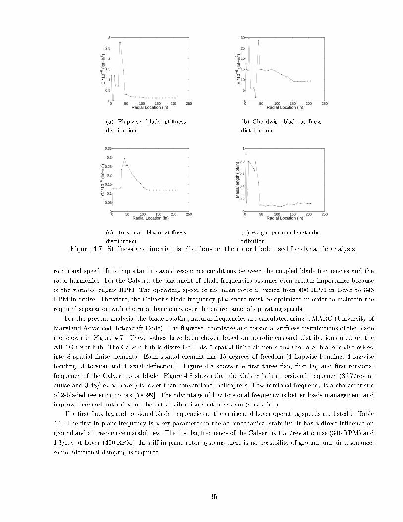
0 50 100 150 200 2500
0.5
1
1.5
2
2.5
3
Radial Location (in)E
I*10
−6 (
lbf−
in2 )
(a) Flapwise blade sti�ness
distribution.
0 50 100 150 200 2500
5
10
15
20
25
30
Radial Location (in)
EI*
10−
6 (lb
f−in
2 )
(b) Chordwise blade sti�ness
distribution.
0 50 100 150 200 2500
0.05
0.1
0.15
0.2
0.25
0.3
0.35
Radial Location (in)
GJ*
10−
6 (lb
f−in
2 )
(c) Torsional blade sti�ness
distribution.
0 50 100 150 200 2500
0.2
0.4
0.6
0.8
1
Radial Location (in)
Mas
s/le
ngth
(lb
f/in)
(d) Weight per unit length dis-
tribution.
Figure 4.7: Sti�ness and inertia distributions on the rotor blade used for dynamic analysis.
rotational speed. It is important to avoid resonance conditions between the coupled blade frequencies and the
rotor harmonics. For the Calvert, the placement of blade frequencies assumes even greater importance because
of the variable engine RPM. The operating speed of the main rotor is varied from 400 RPM in hover to 346
RPM in cruise. Therefore, the Calvert's blade frequency placement must be optimized in order to maintain the
required separation with the rotor harmonics over the entire range of operating speeds.
For the present analysis, the blade rotating natural frequencies are calculated using UMARC (University of
Maryland Advanced Rotorcraft Code). The apwise, chordwise and torsional sti�ness distributions of the blade
are shown in Figure 4.7. These values have been chosen based on non-dimensional distributions used on the
AH-1G rotor hub. The Calvert hub is discretized into 5 spatial �nite elements and the rotor blade is discretized
into 8 spatial �nite elements. Each spatial element has 15 degrees of freedom (4 apwise bending, 4 lagwise
bending, 3 torsion and 4 axial de ection). Figure 4.8 shows the �rst three ap, �rst lag and �rst torsional
frequency of the Calvert rotor blade. Figure 4.8 shows that the Calvert's �rst torsional frequency (3.57/rev at
cruise and 3.48/rev at hover) is lower than conventional helicopters. Low torsional frequency is a characteristic
of 2-bladed teetering rotors [Yeo99]. The advantage of low torsional frequency is better loads management and
improved control authority for the active vibration control system (servo- ap).
The �rst ap, lag and torsional blade frequencies at the cruise and hover operating speeds are listed in Table
4.1. The �rst in-plane frequency is a key parameter in the aeromechanical stability. It has a direct in uence on
ground and air resonance instabilities. The �rst lag frequency of the Calvert is 1.51/rev at cruise (346 RPM) and
1.3/rev at hover (400 RPM). In sti� in-plane rotor systems there is no possibility of ground and air resonance,
so no additional damping is required.
35

0
5
10
15
20
25
30
35
40
0 50 100 150 200 250 300 350 400
Nat
ural
Fre
quen
cy,
Hz
Rotor Speed, RPM
5
4
3
2
1
Operating RPM in Hover
Operating RPM at Cruise
3rd Flap
1st Torsion
2nd Flap
1st Lag
1st Flap
Figure 4.8: Fan diagram of the Calvert rotor blade.
Parameter Cruise Hover
First ap frequency 1.05/rev 1.05/rev
First lag frequency 1.51/rev (sti�-in-plane) 1.30/rev ( sti�-in-plane)
First torsional frequency 3.57/rev 3.48/rev
Table 4.1: Main rotor natural frequencies of the Calvert.
4.3 Rotor blade kinematics and clearances
The unique combination of the intermeshing rotor with the lift compounding wing and the thrust compounding
propeller gives rise to important clearance and safety issues. The maximum ap amplitudes of the main rotor
blades of combat helicopters is of the order of �13� [TNC99]. Since the Calvert is a civil commuter aircraft a
maximum blade apping motion of �10� is considered for studying blade clearances.
For the Calvert, the possibility of the blades striking each other is eliminated by providing a lateral shaft tilt
of 13� (total included angle between the shafts is 26�). This is of the same order as in the K-MAX which has an
included angle of 25� between the rotor shafts.
The clearance between the rotor blade and the wing is improved by giving the wing a 5� anhedral resulting
in a allowable apping motion of 24� which exceeds the 10� requirement for civil transport applications.
The possibility of the rotor blade of one system striking the hub of the other system is examined in Figure
4.9 which is a front view of the helicopter rotor systems. In the baseline position (rotors turning) the blade
subtends an angle of 14� with respect to the horizontal (13� shaft tilt and 1� hub precone). This results in a
vertical separation between the rotor blade and the top of the hub of approximately 0.8 inches with a 10� ap
motion.
36

14ο
Position
ο26
10ο
Horizontal Plane
Max. Flapping (Rotating)
Baseline Position (Rotating Blade)
0.8’’
Figure 4.9: Blade and hub clearances (not to scale).
plane of the papery axis out of
y
Maximum Flapping PositionHUB
PROPELLER
16.88’’
168.39’’
Baseline Position (Rotating Blade)
x 16.28
ο
5.72ο
(a)
xx 1
20’’
167.12’’
(b)
Figure 4.10: Blade and propeller clearances (not to scale).
37

The possibility that the rotor blade can strike the propeller is examined in Figure 4.10 which shows a
schematic top view of the Calvert. Two reference planes are shown. The x-y plane is aligned in the longitudinal
direction with the origin at the rotor hub. The x1-y plane connects the rotor hub and the propeller centerline
with the origin at the rotor hub. (see Figure 4.10). In the x-y plane the blade subtends an angle of 6:3� to the x
axis (includes shaft tilt of 5:3� and hub precone of 1�). However in the x1-y plane the blade subtends an angle
of 6:28� with the x1 axis. In the x1� y plane, the vertical clearance between the x1 axis and the propeller blade
tip is 16.88 inches (this includes a 11.9 inch o�set between the propeller tip and the rotor hub, and an additional
4.98 inches due to the lateral shaft tilt of 13�). Therefore the angle subtended by the propeller tip with respect
to the x1 axis is 5:72�. Consequently, the clearance is 12� (6:28�+5:72�) which is in excess of the maximum blade
ap angle of 10�.
4.4 Vibration and noise issues
Helicopters are susceptible to high levels of vibration and noise due to the unsteady aerodynamic environment
in which the blades operate as well as the coupled structural mechanical system comprised of the rotor, fuselage,
transmission and engine. High vibratory loads result in accelerated fatigue of structural components and re-
duced ride quality. This structural fatigue impacts reliability and maintenance costs, while the poor ride quality
adversely a�ects marketability as a commercial commuter aircraft. The high external noise further degrades mar-
ketability and reduces community acceptance. Because of these reasons, vibration and noise are very important
issues and must be addressed at the very beginning of the design process.
4.4.1 Vibration reduction: passive design features
The Calvert is a thrust and lift compounded synchropter. In cruise, the main rotor is o�oaded. The propeller
provides 80% of the thrust while the wings generate 40% of the lift. Consequently, the main rotor induced
vibratory loads are signi�cantly reduced. In addition the blade frequencies are well placed to minimize the
vibration levels (Figure 4.8). The sti� in-plane 2-bladed teetering rotor is provided with an undersling (1.4
inches) which helps in reducing the Coriolis component of the hub loads. The absence of a tail rotor and a
relatively short. tail boom also help in reducing the fuselage vibration levels.
Additionally, UMARC (modi�ed in-house for Calvert) simulations indicate that the synchropter con�guration
provides a signi�cant reduction in the intrusion index, compared to a single main rotor, 2-bladed helicopter (AH-
1G) and a single main rotor, 2-bladed helicopter with thrust and lift compounding (Figure 4.11). The reason for
the reduced vibration is that the synchropter con�guration provides a signi�cant reduction in the 2/rev vertical
vibration at the pilot's seat due to cancellation of the harmonics from the two individual rotor systems. At the
cruise speed of 180 knots, the vibration intrusion index marginally exceeds the ADS-27 limits. This necessitates
the use of passive vibration isolators/absorbers or an active vibration control system described in the following
section.
4.4.2 Active vibration control
The Calvert is also provided with an Individual Blade Control (IBC) system to provide the passenger with a
jet smooth ride. This IBC system will buy its way into the aircraft via the overall reduced maintenance costs
and improved reliability. In this conceptual stage the �nancial impact in terms of acquisition costs vs reduced
structural fatigue are not quanti�able and needs to be carefully considered in subsequent design iterations. In
addition it is essential to ensure that a failure of the active vibration control system does not compromise the
ight safety of the aircraft.
There are a variety of on-blade activation concepts for IBC. These include active integral twist, servo- aps
and active rotor blade tips. Of these, presently the trailing-edge aps are the most promising option for near term
38

0
1
2
3
4
5
50 100 150 200
Intr
usio
n in
dex
Airspeed (knots)
ADS-27 LIMIT
Conventional 2-bladed helicopter
Compound 2-bladed helicopter
Compound synchropter (Calvert)
Cruise speed (180 knots)
Figure 4.11: Intrusion index for the Calvert.
implementation. The University of Maryland has developed considerable analytic and experimental experience
in the �eld of smart rotor systems. Based on this, it was decided to use a plain trailing-edge ap driven by a
piezo-stack actuator using a double lever ampli�cation mechanism [LC99]. Figure 4.12(a) shows a schematic of
the ap and actuator system. The ap sizing and location are based on the parametric ap performance study
carried out by Milgram and Chopra [Mil97]. The ap parameters are optimized to maximize ap e�ectiveness
and minimize actuation power. For the Calvert a 15% span, 25% chord ap that is located at 70% of blade
radius is selected.
Higher Harmonic Control (HHC) control laws have been widely investigated for vibration reduction using
trailing-edge aps. A signi�cant amount of prior information is required for the HHC formulation, in particular,
the relation between the harmonic content of the control input and the resulting harmonics of the hub loads
oscillation. For the Calvert (synchropter con�guration) such detailed information is not readily available. There-
fore a neural network based approach [SC99] is used to adaptively specify a trailing-edge ap sequence directly
in the time domain. In this application, no o�-line training is performed, instead the network learns in real-time
the appropriate ap de ections that minimize the vibrations. This new algorithm has been implemented in
the University of Maryland Advanced Rotor Code [SC99]. Figure 4.13 demonstrates the vibration suppression
capacity of the neuro-controller for a typical 4-bladed helicopter with an articulated rotor system, for an advance
ratio of 0.35. It is expected that the neuro-controller will be equally e�ective in suppressing the vibratory hub
loads on the Calvert.
4.4.3 SMA-actuated in ight tracking tab
The rotor blade tracking system on the Calvert uses an SMA-actuated trim tab (5% span), located at 55% of
rotor radius. In this scheme, a trim tab together with a controller [EC99] monitors the tracking of the rotor
blades in ight. A Shape Memory Alloy (SMA) actuator is used to de ect the tab to the desired position.
This compact and lightweight system ensures the elimination of aircraft downtime for tracking, a reduction in
vibration due to rotor blades being out of track, and reduction of fatigue loads in the rotor blades and the hub,
leading to substantial maintenance cost bene�ts.
39

Actuator (piezostack)
Pushrod
Flap
(a) Piezo-stack actuated trailing-edge
ap (active vibration control).
Top WireActivated
Bottom WireActivated
Top SMA WireInsulatingMaterial
Bottom SMA Wire
(b) SMA-activated trailing-edge tab (in- ight blade track-
ing).
Figure 4.12: Active aps.
4.4.4 Noise issues
During take-o� the helicopter is, in e�ect, climbing away from its own wake. Thus rotor noise generation is
limited to blade self noise, coupled with noise from turbulence ingestion. Under these circumstances noise from
the tail rotor and the engine are likely to be the more important sources. Due to the absence of a tail rotor the
Calvert is expected to be quieter than a conventional helicopter with the same main rotor tip speed. (Propeller
of the Calvert is non-thrusting in hover and low speed forward ight.) The MD520N (no tail rotor) has an
e�ective perceived noise level of 85.5 EPNdB and hence during take-o� the Calvert will meet the Stage 2 Limit
of 93 EPNdB. There is also a good possibility that the Stage 3 limit (in e�ect in Austria and Switzerland) of 90
EPNdB can also be met.
Now let us consider cruise ight condition. According to Lowson [Low92], the yover EPNL is directly
proportional to the tip speed (raised to 7.8), all up weight (raised to 2), blade area (raised to -1), cruise speed
(raised to 3.3) and blade number (raised to -1). The above formula suggests that the dominant design feature for
a quieter helicopter will be a low tip speed. Note that the Calvert has a variable RPM engine. The tip speed in
hover is 722 ft/sec which is reduced in cruise to 623 ft/sec. The MD520N which is in the same weight class as the
Calvert has a tip speed of 680 ft/sec which is 9% higher than the Calvert in cruise. Therefore the Calvert main
rotor should be signi�cantly quieter than the MD520N. However the Calvert has a propeller which contributes
to the EPNL during yover. In addition the Calvert has a total of 4 blades as compared to 5 for the MD520N,
further increasing the noise levels. The MD520N has an extremely low yover EPNL of 80 dB (the Stage 3 limit
is 90 dB). By virtue of its low cruise tip speed, the Calvert will meet the Stage 2 and Stage 3 limits.
Reduction of noise during approach remains a major issue. The radiation of noise during approach is not
at present accurately predictable. This is due to the inadequacy of the theoretical prediction methods for blade
vortex interaction. Under the circumstances it is impossible to predict with any certainty the EPNL during
approach for a synchropter compound. However the Calvert has advanced geometry blades (similar to the
BERP design) with tip sweep, taper and anhedral which all serve to reduce BVI noise. We were very concerned
that coupling of the wakes of the two rotors could signi�cantly increase BVI noise. We brought up this issue
40

0 2 4 6 8 10 12 14 16 18 200.16
0.17
0.18
0.19
0.2
0.21
0.22
Revs
(a) Time trace for normalized vertical hub
shear.
4/rev 8/rev 12/rev0
0.1
0.2
0.3
0.4
0.5
0.6
0.7
0.8
0.9
1x 10
−3
To 0.0033UncontrolledHHCNN
(b) Harmonic amplitude of normalized verti-
cal hub shear.
Figure 4.13: Active control of vertical shear.
with ight test pilots of the K-MAX during our trip to Kaman Helicopters. According to the pilots and ground
test engineers, the K-MAX does not su�er from this problem during approach; however we feel that ight tests
are necessary to determine whether the Calvert can meet the Stage 2 and Stage 3 certi�cation requirements.
4.5 Propeller design
One of the primary design drivers for the Calvert was to minimize the engine power while working within stall
and compressibility constraints. In an e�ort to keep the fuselage level, minimize shaft tilt, and prevent power
losses due to the dwindling propulsive e�ciency of the main rotor at high forward speeds (see Figure 6.1(a)), the
Calvert uses a propeller that overcomes 80% of the total aircraft drag at cruise velocity. This design required
the selection of several key parameters that de�ne the propeller.
4.5.1 Con�guration
Several con�gurations were studied using standard propeller design charts. These included 4 and 6 bladed single-
and 4 and 6 bladed dual-rotating con�gurations [BH40, Nel44]. A typical tip speed of 230 m/s was chosen for the
propeller. A propulsive e�ciency of greater than 0.8 (at a thrust of 80% of the total aircraft drag in cruise) was
chosen as a design constraint in order to minimize the Calvert's engine power. This choice was made after an
exhaustive trade study involving several di�erent con�gurations, propeller thrusts, propeller weights and cruise
power. The propeller diameters required for achieving an e�ciency of 0.82 at the same thrust (80% of total drag)
for each of these con�gurations are shown in Figure 4.14.
From this trade study, it was found that an increase in number of blades signi�cantly decreased the propeller
diameter for the same e�ciency, or the propeller power for the same diameter. However, contrary to our initial
expectations, there was only a small decrease in diameter from the single to the counter-rotating con�gurations
[BH40]. This decrease was not thought to justify the added complexity in the gearbox arrangement for the
contra-rotating propeller. An optimum design of a 6 bladed propeller (thrust coe�cient=0.13, linear twist=40�,
tip speed=230 m/s, diameter=1.9 m and propulsive e�ciency=0.82 at 180 knots) was chosen for the thrust
augmenting of the Calvert. A Clark YM-15 airfoil (see Figure 4.15(a)) was selected because of its improved
41

Prop Dia(m), efficiency=0.82, Ct=0.13
0
0.5
1
1.5
2
2.5
3
3.5
4
2 bl single 4 bl single 6bl single 4 bl contra 6 bl contra
Propeller Type
Pro
pelle
Dia
met
er (
m)
Prop Dia(m)
Figure 4.14: Variation of propeller diameter for various con�gurations.
thrust e�ciencies at higher speeds over the baseline Clark-Y airfoil. The �nal propeller design is schematically
shown in Figure 4.15(b).
4.5.2 Shaft
Power is transmitted from the engines to the propeller via the transmission. The transmission is designed to
provide the optimum propeller RPM in cruise (see section 4.9). The propeller-transmission separation is 148.1 in
(3.76 m) horizontally and 9.3 in (0.24 m) vertically. Since the axes of the propeller and transmission are vertically
o�set, the shaft must be installed at an angle. Also, in order to avoid potentially damaging resonances while
the engine RPM slowly changes during the transition from hover to cruise, the shaft is designed for subcritical
operation throughout the entire RPM range.
The propeller shaft consists of four sections, each 2 in (50.8 mm) in diameter. The �rst section, which passes
between the engines, is 45 in (1.14 m) long and is attached to the transmission using a exible coupling. The
axis of this shaft section remains aligned with the transmission output axis. This section is titanium to allow
for high temperature operation while maintaining light weight. The remaining three sections are 34.4 in (0.87
m) long and are fabricated from composites. By choosing a uniform shaft length, commonality between each
segment is achieved. The shafts are joined at each end by a Kaman KA ex exible coupling and supported by
bearing blocks. In order to accommodate the vertical o�set between the transmission and propeller, the shafts
must accommodate an angle of 5.15�. This angle is distributed over the three shafts so that the angle between
the axis of any two shafts is only 2.57�. The KA ex couplings can operate continuously at this shaft angle
while still providing enough exibility to allow for shaft misalignment and fuselage bending as well as minimizing
the transmission of loads (with the exception of torque) between the transmission and propeller. The shaft
con�guration is given in the inboard pro�le (Figure 4.1).
4.6 Wing
The Calvert's wing is designed to provide a lifting force in cruise (180 knots) equivalent to 40% of the aircraft
take-o� weight (2026 lbs (9034 N)). In order to minimize added complexity and weight penalty, the wing is
not provided with any control surfaces such as aps or ailerons. The rotor provides 60% of the aircraft lift
42

(a) Clark YM-15 (propeller airfoil). (b) Propeller con�guration.
Figure 4.15: Calvert propeller design.
Figure 4.16: GA(W)-2 (wing airfoil: general aviation (Whitcomb)-2).
required in cruise, providing su�cient control authority for the aircraft. For this moderate freestream velocity,
a General Aviation Airfoil, GA(W)-2 (Figure 4.16, adapted from [Mcg75]) is used. This airfoil was chosen due
to its high Cl/Cd ratios and good low speed stall characteristics. The wing was designed using standard design
codes [Ray92]. The associated wing dimensions are 14.93 ft span, 3.32 ft root chord, 1.66 ft tip chord. The
aspect ratio and taper ratio is 6 and 0.5 respectively. An anhedral of 5� is provided to provide clearance between
the rotor blades and the wing and to improve the Calvert's lateral/directional stability.
The wing is placed aft of the passenger cabin to allow passenger ingress and egress, and for CG balance
considerations in cruise. As a compromise between keeping the center of the lift of the wing as close to the rotor
as possible, and the aerodynamic e�ciency of the wing, a mild forward sweep of 10� is chosen for the wing.
4.7 Empennage sizing
The horizontal tail was sized to trim the aircraft in cruise. For the Calvert, the main rotor lift (LR) and pitching
moment (MR), wing lift (LW ) and pitching moment (MW ), and propeller thrust (Tp) generate a nose-down
pitching moment about the vehicle center of gravity (Figure 4.17). Similarly the rotor and hub drag (Dhub and
Drotor) and the fuselage drag (Dfus) cause a nose-up pitching moment about the vehicle CG. The horizontal
stabilizer generates negative lift due to it's inverted airfoil section. This results in an aircraft nose up pitching
moment, which is used to trim the Calvert in cruise. The horizontal tail is sized by solving the Calvert's pitching
moment equilibrium equation about the vehicle CG. For the horizontal tail sizing, the most forward CG position
was considered (extreme condition). The quarter chord of the horizontal tail is situated 10 feet behind the vehicle
CG. A clearance of 6 inches is maintained between the trailing-edge of the horizontal tail and the propeller. The
43

horizontal tail has an inverted GA(W)-2 airfoil section and the aspect ratio is set at 6. The horizontal tail is sized
such that the operating angle of attack (for most extreme CG position) is 5.4� (lift coe�cient of 0.6). The span
of the horizontal tail is 86.4 inches and the chord is 14.4 inches. The horizontal tail is unswept and untapered
and is free to pitch about the quarter chord. The horizontal tail pitch attitude required to trim the aircraft
depends on the CG location, forward speed and ight condition (climb, descent, cruise, autorotation etc). In
hover the horizontal tail loses its e�ectiveness and the fuselage will tilt slightly forward.
MAIN ROTOR
D hub+ DrotorM R
LR
Center of Pressure (WING)
LW
M W
TP
PROPELLER
L HT
HORIZONTAL TAIL
Vehicle CG
W
FUSELAGE
D fus
Figure 4.17: Vehicle trim in cruise (not to scale).
The vertical tail assumes great importance from the point of view of aircraft stability. This is particularly
true for a synchropter con�guration which can be susceptible to spiral instabilities while conducting turns in
high speed forward ight. We visited Kaman Helicopters in late May and discussed these issues with several
design engineers at Kaman. The K-MAX has three vertical �ns which are speci�cally designed to prevent such
dynamic instabilities. For the present design, the Calvert has three vertical tails which have been designed to
mimic the K-MAX vertical stabilizers. The vertical tails at the end of the horizontal stabilizer have a root chord
of 3 feet and a tip chord of 2 feet. The height of each vertical �n is 4 feet. The central �n which also provides
the rear support point has a height of 4 feet, root chord of 3 feet and tip chord of 2 feet.
4.8 Engine
During the development of the Calvert, a parallel engine development will be undertaken as stated in the RFP.
The Calvert requires a power plant which provides a maximum continuous power of 1050 HP (783 kW) maximum
continuous. Hence, a two engine con�guration was chosen for safety with each engine rated at 525 HP (391 kW)
maximum continuous.
4.8.1 Characteristics
The engine characteristics have been determined using the equations in the RFP. In order to achieve the desired
installed power (525 HP), a take-o�/contingency power of 656 HP (489 kW) is required. This power requirement
leads to an engine 27.3 in (.693 m) in length and 17.5 in (.445 m) in diameter, with a weight of 173 lb (78 kg).
The output shaft speed is speci�ed as 21000 RPM. However, an additional requirement of the Calvert engine
is the ability to provide constant power over a range of rotational velocities. In hover, the Calvert requires
a rotor speed of 400 RPM (the engine is operating at 21000 RPM). During transition to cruise, the rotor is
44

slowed to 346 RPM (see Figure 6.4) which requires that the engine be slowed to 18136 RPM, a decrease of 14%.
This technology has been proven by Mitsubishi Heavy Industries (MHI) who developed the MG5-100 turboshaft
engine for their MH2000 helicopter. The MG5-100 has the ability to operate at two distinct RPM levels. In
addition, the NASA Glenn Research Center has explored the concept of a broad-spectrum engine capable of
operating with high power and good speci�c fuel consumption with as much as a 50% reduction in RPM [Tal91].
Thus, the variable RPM engine for the Calvert is considered feasible.
4.8.2 Performance
The engine of the Calvert was sized in order to meet the stringent high-speed requirement. A parallel engine
development will be undertaken to develop two scalable Integrated High Performance Turbine Engine Technology
(IHPTET) engines. The target for the IHPTET program is to incrementally achieve a signi�cant increase (120%)
in the power/weight ratio and a signi�cant decrease (40%) in SFC.
Phase I (complete): +40% Power/Weight, -20% SFC
Phase II (complete): +80% Power/Weight, -30% SFC
Phase III (by 2003): +120% Power/Weight, -40% SFC
An additional advantage of the IHPTET engine is that it o�ers a very high short period emergency setting
of 125% for 30 sec. The stipulated engine power includes several losses for installation (1%), gearbox (2%),
compressor bleed (2%) and engine accessories (2%), as well as a power margin of about 5% to account for future
growth. The engine given in the RFP is found to satisfy the required functions with a small increase in SFC
at the design cruise speed of 180 knots (Figure 6.11(b)). The engine must be capable of delivering a relatively
constant e�ciency at a range of output shaft speeds not exceeding 15% of the initial rated output shaft speed
(21000 RPM). Table 4.2 lists the various power ratings of the engine.
Settings Time Limit Power Ratio� Power SFC
shp (kW) lb/shp/hr (kg/kW/hr)
Emergency 30 sec 1.25 820 (611) 0.40 (0.24)
Take-O�/Contingency 2 min 1.00 656 (489) 0.36 (0.22)
Intermediate 30 min .924 606 (452) 0.36 (0.22)
Max. Continuous - .800 525 (391) 0.38 (0.23)
Partial - .500 328 (245) 0.53 (0.32)
Idle - .200 131 (98) 0.81 (0.49)
� The power ratio is de�ned with respect to the nominal, uninstalled engine power.
Table 4.2: Calvert engine data (static, ISA, mean sea level).
4.8.3 Structural integration
The engine installation is given in Figure 4.18. The engines are located on the transmission deck behind the
main gear box and have a center separation of 20 in (0.508 m). This location allows for good accessibility for
maintenance and inspection. The engine/transmission cover may be opened and doubles as a work platform
while the systems are being serviced. Each engine is mounted to the transmission deck using two bipods and
two linkages. Torque is transferred to the transmission using a exible coupling. In addition, since the propeller
shaft must pass between the engines, the �rewall separating the engines has been appropriately designed to
accommodate it.
45

Figure 4.18: Engine installation.
4.8.4 Oil system
In order to improve reliability and safety, an independent oil system is provided for each engine. The oil system
is assumed to be an integral part of the engine. Each system consists of a pump, tank, �lter, cooler and two
particle detectors. The particle detectors are monitored by the FADEC system. Each engine is estimated to use
1.59 gal (6.02 L) of oil given that the Calvert engine has an advanced design and the engine oil consumption
decreases with each generation of engine. This oil capacity complies with F.A.R. x27.1011 (see section 4.9.4).
4.8.5 Particle separator
In order to minimize the risk of engine damage from dirt/debris ingestion, a particle separator is installed at
each engine inlet. The particle separator is designed for e�cient operation by increasing ow capacity and
incorporating three �ltration areas. Each separator is easy to access and remove for cleaning and maintenance.
In addition, separator blockage is monitored by the FADEC system.
4.8.6 FADEC
The engine is integrated into the ight control system using the FADEC (full authority digital engine control)
system. The FADEC system controls the overall engine settings to ensure optimal performance during nominal
as well as OEI ight conditions [Bel97]. The engine, engine oil system and particle separator sensors are also
monitored and any problems are reported to the Calvert PHM system (see section 4.14.2) for compensation. A
signi�cant additional function of the FADEC system for the Calvert is to ensure a linear variation in the engine
rotational velocity, and thus the rotor tip speed, during transition between ight regimes as shown in Figure 6.4.
The engine speed variation is displayed to the pilot in order to simplify ight operation.
4.8.7 Safety
Modern engines are very safe and reliable. The engines to be used in the Calvert have been designed so that a
catastrophic turbine failure, considered the worst case failure, will be con�ned within the engine. In the event of
an uncon�ned turbine failure, the transmission deck provides an additional layer of protection for the passengers
46

and crew. In addition, any problems detected by the FADEC system is relayed to the PHM system. The PHM
system then alerts the pilot of the problem (see section 4.14.2).
4.9 Transmission design
The Calvert transmission con�guration is driven primarily by two design requirements. The �rst requirement is
the ability to operate under two disparate ight conditions: take-o�/hover and cruise. The Calvert powerplant
consists of two engines rated at 656 shp (489 kW) take-o�/contingency with a nominal speed which varies from
21000 RPM at takeo� to 18136 RPM at cruise. During takeo�, the main rotors rotate at 400 RPM and draw 317
hp (236 kW) each while the propeller (set to zero pitch) draws 147 hp (110 kW). Since the propeller is set at zero
collective pitch (non-thrusting condition), its rotational velocity is unimportant. At cruise, the main rotors are
slowed to 346 RPM and unloaded such that each rotor draws 103 hp (77 kW). In this ight regime, the propeller
has a rotational velocity of 2308 RPM and draws 844 hp (629 kW). Given the mission pro�le in Figure 2.2, the
Calvert spends the majority of its ight time in cruise. Thus, to increase the life of the gears which drive the
main rotors, the transmission should distribute power separately to the main rotors and propeller. Speci�cally,
the gears which drive the main rotors alone should be o�oaded when the main rotors are o�-loaded.
The second requirement for the Calvert transmission is the desired geometry. The transmission must accept
input from two engines with a separation of 20 in (.508 m). In addition, the propeller output should be located
between the two engines such that the propeller shaft can pass between the engines with enough clearance for a
�rewall. The propeller shaft should also be as low as possible to minimize the propeller shaft angle. The main
rotor shafts are tilted outboard 13� from vertical (26� included angle) and forward 5.3�. The center separation
of the rotor shafts at the transmission base is 28 in (.711 m).
4.9.1 Con�guration
The resulting transmission con�guration is given in Figure 4.20. Gear design was performed using the methods
presented in the Handbook of Practical Gear Design by Darle W. Dudley [Dud84] as well as Tishchenko's method
[TNC99]. The design transmission power ratings are given in Table 4.3. Note that the transmission was designed
using 85% RPM since this is the higher tooth load case and thus an added margin of safety is provided.
To transmit torque from the engines to the transmission inputs, a exible coupling is required. Lucas
Aerospace exible couplings were chosen due to their single piece design that is light weight, highly reliable, and
easy to maintain. At the transmission inputs, the torque is accepted by a spring-type overrunning clutch (see
Figure 4.19(a)).
The input is the location of the lowest driveline torque and thus, placing the clutch at this point allows its
weight to be minimized [Whi98]. However, the input is also the location of the highest rotational velocity. Since
spring clutches can operate at these velocities [Kis78], they were deemed ideal for this application. In order to
keep the clutch assembly compact, the clutch is mounted inside the input pinion.
The �rst reduction stage consists of a 10-pitch, 30-tooth input pinion which drives a 54-tooth spur gear,
both of which have a face width of 1.5 in (38.1 mm). Integral with the spur gear shaft is a 10-pitch, 25-tooth
double-helical pinion. Each face of the double helix is 1.5 in (38.1 mm) wide yielding a total face width of 3 in
(76.2 mm). The spur gear/double-helical pinion is allowed to oat axially to control the load-sharing between
the halves of the double helix. A single 109-tooth double-helical bull gear is driven by both pinions. This gear
collects the torque from the engines and distributes it back to the propeller and forward to the main rotors. The
rotor brake is mounted to the propeller shaft output. In this case, a Kaman KA ex exible coupling is used to
attach the propeller shaft. The KA ex couplings were chosen as a result of their ability to operate continuously
at the desired propeller shaft angle, eliminating the need for a universal joint (see section 4.5.2).
The total reduction of the �rst two stages is 7.848:1, chosen to provide a nominal propeller rotational velocity
47

Settings Time Limit Power
shp (kW)
One Engine Inoperative (OEI)
(transmission input limit)
Emergency 30 sec 845 (630)
Contingency 2 min 815 (608)
Intermediate 30 min 678 (506)
Continuous - 656 (489)
All Engines Operating (AEO)
(double-helix stage limit�)
Take-O�/Contingency 2 min 1320 (984)
Intermediate 30 min 1215 (906)
Max. Continuous - 1070 (798)
� The double-helical gear is the transmission maximum load point.
Table 4.3: Transmission ratings at 85% engine RPM (maximum tooth load).
of 2308 RPM in cruise. Since the engines are slowed for cruise, the reduction will yield the optimum propeller
speed with the slower engine speed. Subsequently, during takeo�/hover, the propeller rotates at a higher than
optimal speed. However, in this ight regime, the propeller blades are set to zero pitch.
To distribute torque to the main rotors, a 4.8-pitch, 40-tooth spiral bevel pinion with a face width of 1.75
in (44.5 mm) is spline mounted to the collector gear. This pinion drives a 47-tooth spiral bevel gear, spline
mounted to the cross shaft, resulting in a 90� change in the axis of rotation. A 4.8-pitch, 28-tooth spiral bevel
pinion with a 2 in (50.8 mm) face width is spline mounted to each end of the cross shaft. Each pinion drives
a 52-tooth spiral bevel gear. The shaft angle is 77� (to provide the 13� outboard shaft tilt) and the shafts are
rotated 5.3� forward about the cross shaft axis. The �nal reduction stage is a planetary gear set. A 7.5 pitch,
41-tooth sun gear with a 2 in (50.8 mm) facewidth is mounted on the same shaft as each of the 52-tooth spiral
bevel gears. The each sun gear drives six 22-tooth planet gears. The �xed 85-tooth internal ring gear is splined
to the housing. The planet carrier is mounted to the rotor output shaft.
An important consideration in the design of this last stage is that the power is not necessarily distributed
evenly between the two rotors, especially during maneuvers. Thus, each �nal stage was designed to handle 75%
of the total rotor load in hover. The con�guration of the �nal three reduction stages is similar to that used by
the Kaman K-MAX [OG97], and ensures that the required counter rotation and phasing occurs. The reduction
of these three stages is 6.706:1; yielding a total reduction of 52.63:1, which is designed to provide a nominal main
rotor rotational velocity of 400 RPM in hover.
In addition to the main rotor and propeller outputs, two take-o�s are provided for the electrical system.
The Calvert has a redundant electrical system that uses two independent alternators. Each alternator output
is driven by an 20-tooth spiral bevel pinion (with a face width of 0.5 in (12.7 mm)) which meshes with the 4.8
pitch, 52-tooth spiral bevel gear yielding a rotational velocity of 3188 RPM in hover and 2753 RPM in cruise.
The alternators were chosen to provide su�cient performance over this RPM range.
4.9.2 Structural integration
Typically, rotor mast loads are transfered to the helicopter fuselage via the transmission housing. However, the
synchropter con�guration subjects the rotor mast support system to load environments that can be more severe
48

(a) Spring clutch. (b) Standpipe mast support system.
Figure 4.19: Clutch and standpipe (not to relative scale).
than those experienced by a conventional helicopter. In order to minimize the rotor loads experienced by the
transmission housing, an independent truss support, referred to as a standpipe, has been incorporated for each
main rotor (see Figure 4.19(b)) [Kis93]. As in conventional rotorcraft, the rotor shaft carries the mast moment,
thrust, side loads and torque. However, the standpipe transfers all loads but the torque directly to the fuselage.
This con�guration reduces the weight and increases the fatigue life of the transmission.
Each standpipe consists of a bearing housing and three legs, all manufactured from titanium. The bearing
housing contains two tapered roller bearings and the rotor shaft. The three legs are attached to the bearing
housing and then mounted to the transmission deck using nodal vibration isolators. An additional provision has
been made to include active vibration cancellation in the legs. Torque is carried between the transmission and
the rotor shaft by a steel quill shaft that has a ange designed to react minimal head moment, thrust and side
loads while easily carrying the maximum torque loads. The quill shaft is mounted between the transmission
output quill and the main rotor shaft.
4.9.3 Housing
The primary function of the transmission housing is to support and enclose the main transmission components,
in addition to reacting the residual loads transferred by the quill shaft. The housing consists of four sections
bolted together, each section cast from a magnesium-zirconium alloy. The bottom half of the gearbox is a single
continuous casting and the top half is divided into three separate sections. Care must be taken during the
detail design stage to eliminate any possibility of oil leakage between the housing sections. Cored passages are
incorporated into the housing to transfer lubricant to the gear meshes and bearings and an oil sight gauge is
included to check the oil level. The transmission housing is mounted to the transmission deck via the same
vibration isolators used by the standpipe legs.
4.9.4 Oil system
The basic components of the Calvert transmission oil system are the oil �lter, magnetic particulate trap (MPT),
cooler, pump, and fan. Two separate oil �lters are installed, one at the sump and the other at the MPT output.
The MPT will detect metallic particles and burn up small particles with a high voltage spark. Both �lters will
49

contain element detect switches (to ensure the �lters are installed and operating properly) and bypass valves
allowing for continued transmission operation if the �lters are clogged. The MPT and �lters each have integral
alarms and any abnormal operation will be reported to the Calvert prognostic and health management (PHM)
system. An visual oil level gauge is provided for each oil tank. Each indicator is easy to view from outside the
aircraft without opening or removing any panels.
F.A.R. x27.1011 states that the helicopter is required to carry 1 gal (3.8 L) of oil for every 40 gal (151.4 L) of
fuel. Given the 182.5 gal (690.8 L) fuel capacity, the F.A.R. would require an oil capacity of 4.56 gal (17.26 L).
Analysis of the transmission indicated a worse case 98% e�ciency. At an operating condition of 1320 hp (978.3
kW), this results in 26.4 hp (19.69 kW) being dissipated as heat. A preliminary heat transfer analysis was used
to size the transmission oil requirements. The heat ux is calculated from the transmission e�ciency given the
maximum oil temperature, the design oil cooler out ow temperature and the constant pressure speci�c heat of
the oil. Modern oil cooler designs allow an oil inlet temperature of 230�F (110�C) and a transmission outlet
temperature of 450�F (232:2�C) [HB93]. The mass ow rate is given as
_m =q
cp � (Thin � Thout)(4.1)
where q is the power dissipated, cp is the constant pressure speci�c heat, and Thin and Thout are the oil inlet and
outlet temperatures, respectively. From Equation 4.1, the resulting oil ow rate is 1.3 gal/min (4.92 L/min).
Total oil capacity, based on a 16 second recycle time is 0.347 gal (1.31 L). This quantity is quadrupled to 1.39
gal (5.26 L) to provide a large safety margin. In addition, each engine will require 1.59 gal (6.02 L) (see section
4.8.4) of oil yielding a maximum oil capacity of 4.57 gal (17.3 L). This value is in compliance with the F.A.R.
If the oil leaks at the maximum ow rate, the pilot will have one minute before the transmission runs dry to
e�ect a landing. However, if a landing cannot be made within this time, the main gear box will have the capacity
to operate for 30 minutes dry but will require a tear down inspection after landing. A thermostat controlled
electric fan provides positive air ow when the airspeed provides insu�cient ventilation.
4.9.5 Summary of transmission advanced technologies
A number of advanced technologies have been incorporated into the Calvert transmission to reduce weight and
improve reliability. These technologies are summarized below.
� Advanced alloys and treatments used for gears to increase the allowable bending and surface stress and
maximum operating temperature.
� High-contact ratio gear tooth geometry for noise and vibration reduction and an increased operational life.
� Spring clutch for higher speed operation resulting in reduced weight.
� Ceramic spherical roller bearings for increased operational life.
� Standpipe/quill shaft rotor mast support system to reduce the loads experienced by the transmission
housing yielding a transmission weight reduction and fatigue life increase.
� High temperature oil system.
� Advanced PHM system (see section 4.14.2).
50

Figure 4.20: Transmission schematic.
51

4.10 Landing gear design
The Calvert has a retractable tricycle landing gear with two main wheels and a nose wheel (see section 2.4.4). The
landing gear location has been driven by three major requirements. First, the relative position of the rear wheels
versus the vehicle CG is such that the main wheels support 73% of the aircraft weight and the remaining 27% is
supported by the nose wheel at aircraft gross weight. This provides good ground handling performance. Second,
the track and wheel base dimensions give an overturn angle of 62.3� worst case. This is within a recommended
limit of 63� [Ray92] to avoid aircraft turn-overs during a landing or ground maneuver. Finally, the landing gear
location takes into account crashworthiness considerations. If a vertical crash occurs with wheels fully lowered,
the main gear will not penetrate the passenger cabin and the nose gear will go through the oor beneath the
instrumentation console in front of the crew.
(a) Front view.
���������
�����
���
��� ��
��������
��
�� �����
�������
��
(b) Isometric view.
Figure 4.21: Main landing gear.
4.10.1 Con�guration
In order to keep the turn-over angle within the suggested limit, the main wheels are set 46.8 in (1.19 m) from the
centerline and 154.5 in (3.9 m) from the nose of the aircraft. Thus, the extension/retraction con�guration must
pull the wheels toward the center of the fuselage as well as up. This is achieved via an A-frame mounted 35� from
vertical (see Figure 4.21). This con�guration is similar to that used by the Kaman SH-2G Super Seasprite, and
was chosen due to its simplicity and small stowed frontal pro�le. Given the fuselage space limitations, the main
gear is designed to retract back into the base of the Calvert's tail. Disk brakes are installed in the rear wheels
to hold the aircraft stationary when parked and to provide braking during ground rolls. A positive down lock
and mechanical up lock are incorporated to prevent unexpected gear motion.
The nose wheel is set 33.6 in (0.85 m) from the nose of the aircraft to ensure stability during ground maneuver.
52

(a) Side view extended. (b) Side view retracted.
Figure 4.22: Nose landing gear.
The steering control uses a turning nose wheel actuated by a push-pull device that also incorporates a shimmy
damper. The pilot controls the aircraft using rudder pedals linked to the nose wheel. The maximum turning
angle of the wheel is 60�, which allows all ground maneuvers to take place within a reasonable space. Given the
limited vertical space at the nose gear location, the retraction mechanism has been designed to rotate the wheel
90� so that it is horizontal when stowed (see Figure 4.22). Once again, a positive down lock and mechanical up
lock are incorporated to prevent unexpected gear motion.
4.10.2 Tire sizing
Low pressure tires have been selected to allow the aircraft to land on semi-prepared runways. At gross weight,
each main gear tire must carry (static) 1850 lb (839 kg). Hence, Type III 5.00-4 tires with a maximum load
of 2200 lb (998 kg), 12 plies and an in ation pressure of 95 psi (0.66 MPa) were chosen. The nose gear tire is
sized for dynamic breaking loads. From Raymer [Ray92], this load is 762 lb. Thus, a Type III 5.00-4 tire with a
maximum load of 1100 lb (499 kg), 6 plies and an in ation pressure of 55 psi was chosen.
4.10.3 Oleo sizing
Single oleo-pneumatic shock absorbers are used for both main and nose gear. The stroke is sized to meet FAR
x27.725: each gear must be able to withstand a 13 inches drop test (vertical touchdown velocity of 8.35 ft/s).
Assuming a tire stroke (1/3 radius) and shock absorber e�ciencies of 0.47 (tires) and 0.85 (oleo), the estimated
stroke equals 3 in (76.2mm). The value is increased to 4 in (101.6mm) to account for any errors and provide
a margin of safety[Cur88]. Oleo sizing design requirements are [Cur88]: internal pressure of 1800 psi, external
diameter of 1.3 times the internal diameter, length of 2.5 times the stroke, external diameter related to static load
(for main wheels) and to dynamic load (for nose wheel). The main gear incorporates a mechanical advantage
system to reduce the required oleo stroke for a given wheel stroke. This system is included in the oleo sizing
computations. The resulting oleo speci�cations are: nose gear outside diameter 1.54 in (38.4mm) and length
12.52 in (254mm) and main gear outside diameter 2.5 in (63.5mm) and length 7.3 in (185.4mm).
53
4.11 Airframe
The Calvert airframe consists of a substructure which supports the fuselage skin panels, external structures and
internal components. The airframe has been designed to meet the FAR 27 crashworthiness requirements.
4.11.1 Substructure
The Calvert uses seven primary metal bulkheads and several smaller bulkheads for load transfer and to maintain
structural shape (see Figure 4.1). The �rst primary bulkhead is at the front of the cockpit and supports the nose
gear, the avionics bay, and the nose section of the aircraft. The crew seats and rear-facing passenger seats are
suspended from the second primary bulkhead, which separates the cockpit from the main passenger cabin. By
suspending the seats from the bulkhead, the belly tanks can safely carry fuel without fear of puncture by energy
absorbing seats that might otherwise stroke into the oor. Additionally, this second primary bulkhead forms
the front support for the transmission deck. The third primary bulkhead forms an intermediate support for the
transmission deck and the front of the rotor mast support standpipes. The fourth primary bulkhead forms the
rear of the passenger cabin and the rear support point for the transmission deck. It is also the mounting point for
the forward-facing passenger seats, and the front mounting point for the engines. The aft mounts of the engines
are on the �fth primary bulkhead, which also supports the rear of the fuel system. The �nal pair of primary
bulkheads sit at the end of the tailboom. The forward one supports the empennage, while the aft one supports
the propeller shaft and propeller bearing. The fuselage skin panels are attached to the primary and secondary
bulkheads
To support the cabin oor two keel beams are mounted to the primary bulkheads. The keel beams run
between the �rst and fourth primary bulkheads. Keel beam sections with sine wave webs have been chosen as they
have been proven to exhibit good crash energy absorption characteristics. This ensures fuselage crashworthiness.
4.11.2 Tail boom
The synchropter con�guration lends itself to a short tail boom resulting in weight savings. The tail boom is
a semi-monocoque structure (see Figure 4.1). There are only two structural bulkheads within the tail, and all
of the loads from these bulkheads are transmitted by the stringers, minor bulkheads, and skin to the primary
substructure. The propeller shaft bearings are supported by the minor bulkheads.
4.11.3 Pylons
The pylons are designed to support the rotor system. To reduce drag, each pylon incorporates an aerodynamic
fairing that encloses the stand-pipe, rotor shaft, non-rotating controls and the swashplate. This fairing terminates
6 inches below the rotor hub and reduces the number of exposed linkages to two (pitch links). The top of the
fairing terminates in a specially designed ange to minimize interference drag (wind tunnel tests are necessary
to determine the ange pro�le).
4.12 Subsystems
4.12.1 Inlet and exhaust system
The Calvert has three inlets; the two primary inlets provide air for the engines and the secondary inlet provides
air for the cooling system and cabin ventilation. The primary inlets are located aft and outboard of the pylons
as shown in the inboard pro�le (see Figure 4.1). The particle separator is mounted at the inlet ush with the
fuselage. The secondary inlet (a NACA ush inlet) is located between the pylons.
54

The exhaust system is designed to take into account heat, corrosion, thermal expansion and to optimize
for pressure recovery. The exhaust ducts extend just past the fuselage and are surrounded by another set of
composite ducts. This outer shell serves three purposes: it ensures that air is circulated around the exhaust
ducts for cooling, provides for smooth air ow minimizing drag, and adds rigidity to the aft fuselage.
4.12.2 Fuel system
The Calvert has a required fuel capacity of 182 gal (689 L) (see section 5.2). For crash worthiness, the fuel
tanks should only be �lled to 70% of their total capacity. The resulting fuel tank volume is 274 gal (1036 L),
allowing an additional 3% for the tank wall thickness. To accommodate this requirement, six main fuel tanks
are incorporated; four below and two behind the passenger cabin. Each of the four tanks below the cabin has
a volume of 35.9 gal (135.8 L) and each of the two tanks aft of the cabin has a volume of 65.2 gal (246.4 L).
Placing the fuel below the cabin oor eliminates the need for sponsons and ensures an aerodynamically clean
con�guration. It should be noted that the crashworthy seats are mounted to the bulkheads rather than the oor
to avoid puncturing the fuel tanks in the event of a crash (see section 4.11.1). The Calvert's fuel system has been
designed to maintain independent fuel supply to each engine. Electric booster pumps are provided inside each
main fuel tank. The fuel tanks will be cross connected to ensure even fuel levels. In addition to the main fuel
tanks, there are two collector tanks (one for each engine). Each collector tank is equipped with an independent
fuel pump.
4.12.3 Fire protection systems
Post-crash �re is an ever present danger and the source of many fatalities. Great care was taken in this design
to ensure that the passengers and crew are shielded from potential �re hazards. Shuto� valves and self-sealing
breakaway couplings are used to prevent post-crash �res. Proper grounding of the fuel system will minimize
potential lightening strike damage. Large doors on both sides of the cabin and cockpit provide adequate vehicle
egress. The fuel is stored in crashworthy tanks below the cabin oor and the fuel lines run behind the fourth
primary bulkhead from the fuel tanks to the transmission deck. This ensures there will be no fuel or vapors
in the cabin. Manually operated and thermostatically regulated HALON bottles are provided to suppress any
engine �re. Temperature, and smoke alarms are provided, to alert the pilot to any potential problem.
4.12.4 Heating, ventilation, air conditioning, and anti-ice (HVACAI) system
The windshield and window defrosting, cockpit and cabin heating, and cockpit anti-ice systems use hot engine
bleed air. No combustion heaters are used for safety reasons. Separate anti-ice plumbing is provided for the
empennage and engine inlets. The anti-ice system has been designed for outside air temperatures of 15� to 30�
(�9:4� to �1:1�C), as per FAR requirements. Since the Calvert is high speed cruise power limited, bleed air is
available for anti-ice in all ight regimes. The anti-ice ability will allow the vehicle to safely pass through icing
altitudes. The rotor hub will need no anti-ice since all movable controls are internal to the pylon fairings. A
heating strip is incorporated into the rotor blade leading edge cap for de-icing.
The source of the cabin and cockpit air ow is engine bleed air. The HVACAI system has been designed to
preclude excess fuel vapor and engine exhaust from entering the cabin and carbon monoxide detectors provide
additional safety. Outside air for ventilation is provided by the secondary inlet located between the pylons.
Separate cooling systems are provided for the transmission, engine and cabin. Air for each of the cooling
systems is provided by the secondary inlet. The cabin cooling system heat exchanger is located in front of the
transmission. Hot bleed air will be sent through the heat exchanger to cool the air as required for air conditioning.
The cockpit, cabin and avionics are cooled by this air conditioned air.
55

Figure 4.23: Cabin layout.
4.13 Interior layout
Given the mission ight time of three hours, comfort is an important consideration for the Calvert. Thus, the
interior layout has been optimized to provide comfort for passengers and crew alike while minimizing the drag
penalty associated with high speed ight.
4.13.1 Cabin
Few helicopters routinely travel at speeds for which the Calvert has been designed. These high speeds require
the fuselage frontal area to be minimized in order to keep parasite drag to a minimum. In order to minimize the
frontal area, the seating is provided in three rows of two seats each (see Figure 4.23). By seating passengers only
2-across and providing doors on both sides of the fuselage, the Calvert avoids the need for additional height for
passengers to enter and exit the fuselage. Hence, the headroom can be sized for a person in the seated position.
The resulting passenger compartment height and width are 52 in and 43.5 in, respectively. The seat pitch of 35
inches provides adequate leg room. The volume of the passenger compartment and cockpit is 127.9 ft3, which
gives a volume per person of 21.3 ft3 This is greater than the Augusta 119 (15.25 ft3) and the Bell 407 (18.0
ft3). The seats are mounted to primary bulkheads for crashworthiness (see section 4.11.1).
4.13.2 Doors
Four doors have been provided for ingress and egress. The crew enters and exits the cockpit using standard
hinged doors that swing forward. Passengers access the cabin via \clam-shell" doors located on either side of
the fuselage. The lower half of each door doubles as a step to ease ingress and egress.
4.13.3 Cockpit controls
A glass cockpit improves pilot visibility, and a careful design of displays and advanced avionics keeps pilot
workload to a minimum. Dominating the pilots instrument panel are two large at panel displays, 5.5 in (139.7
mm) by 7.5 in (190.5 mm), stacked one above the other. These multi-functional displays (MFD) work as the
primary ight instruments and provide visual cues for system monitoring. An MFD con�guration was chosen
since at panel displays are cost e�ective, reliable and more versatile than the plethora of gauges, bars and dials
they replace. The upper MFD is the primary ight instrument display. The required instruments consisting
of an airspeed indicator, an altimeter, and a magnetic direction indicator will be augmented with a slip-skid
indicator, an arti�cial horizon and a clock to ease piloting. The lower MFD contains performance gauges for
56
engine parameters, (oil temperature/pressure, turbine temperature and RPM, gas generator speed, and torque),
main rotor and propeller RPM, propeller pitch, and a fuel gauge for each tank. In addition, the prognostics and
health management system (PHM) (see section 4.14.2) status and documentation will be displayed on the lower
MFD. To ensure fail-safe operation, the MFD system provides redundancy: if one at panel display fails, the
other can display all of the most vital information. Basic analog gauges are also included.
The overhead panel is reserved for the helicopter startup, shutdown and rotor controls. The center console
holds the throttle and landing gear controls as well as the radio equipment. The basic instrumentation package
will be VFR only. Since helicopters operate under much less restrictive rules than �xed-wing aircraft, this is not
a major limitation. However, the provision for expansion to full IFR instrumentation is provided.
4.14 Reliability and maintainability
A safe, a�ordable and dependable helicopter must have good reliability and maintainability (R&M). The direct
operating cost (DOC) of a helicopter is directly related to its R&M. For the Calvert, the $217/ ight hour main-
tenance costs (including scheduled inspection, overhaul retirement, unscheduled maintenance and on condition
maintenance - see section 8.2) constitute approximately 40% of the DOC per air-seat-mile. Adequate R&M
can be achieved when it is included in the design process. This is a constraint placed upon the designer in
addition to manufacturing, corrosion, weight, and cost constraints. Additionally, R&M considerations tend to
increase development costs. However, upfront attention to R&M pays for itself many times over during the life
of the helicopter, as has been adequately demonstrated by many US military programs, especially the numerous
unmanned aerial vehicle programs where costs skyrocketed due to a lack of R&M planning. Thus, R&M has
been included as a major factor in the development plan of the Calvert.
4.14.1 Accessibility
A helicopter designer has the goal of ensuring that each part may be inspected, serviced, and replaced with single
level access; i.e. the inspection of any primary part should not require the removal of another. For example, the
engine should not need removal to service the transmission. Adequate access panels are the single most important
item for ease of maintenance. The fuselage is made from composite panels bolted to a frame. Hence, access
panels have been incorporated during the design stage itself to avoid costly rework of the moulds. In addition,
there should be a high commonality of fasteners and subsequently, a limited number of tools are required to
remove any line replaceable units (LRU's).
Easy access to the drive system, including the transmission, engines, and shafting, is of utmost importance
since these systems constitute the vast majority of inspection and maintenance hours. The upper fuselage is
designed as a left and right cowling, each of which can be easily opened providing access to the transmission
and engines. In addition, the interior of each cowling serves as a work platform. The rotor pylon fairings are
also easily removable to give access to all rotating assemblies. If additional access is needed, the entire upper
fuselage skin may be removed for full access. The propeller and the propeller shaft and bearings can be accessed
by removing skin panels in the aft fuselage.
4.14.2 Prognostics and health management
A proven method to reduce maintenance costs is to only perform maintenance when needed; i.e. base helicopter
maintenance on condition. In order to successfully perform condition based maintenance, each primary system
of interest should be continuously monitored for signs of abnormal performance or incipient damage. Once a
potential problem is detected, the nature of the problem is determined and a prognosis of the remaining life
of the system is computed. The prognosis is given to the pilot along with suggestions for limitations on the
ight envelope to maximize the remaining life. The Calvert will include a fully integrated, comprehensive and
57

robust prognostics and health management (PHM) system. The primary systems monitored are the transmis-
sion, engine, rotor system and propeller system as well as certain miscellaneous subsystems. In addition, the
PHM system includes a system for self-diagnosis, so that, for instance, sensor failures do not lead to erroneous
indications. The PHM system status and documentation is shown on the multi-functional display. In the case
of a malfunction, the PHM system ags the fault, displays the checklist and provides emergency procedures.
Under normal operating conditions, the PHM system records only small data sets at large time intervals.
However, upon the detection of a potential fault, the PHM system begins recording larger data sets more
frequently. Upon landing, this data will be downloded by maintenance personnel and will aid in the analysis
of the problem. The central PHM unit is a self contained box which receives data from each sensor. In order
to minimize the required wire runs, data transfer from more distant sensors is performed wirelessly using a
spread spectrum technology with multi-path and data relay capabilities [SPT98, BLN99]. Speci�cally, each
sensor node can act as a data relay path for sensors, either too distant to the central PHM or whose data
path is blocked by intervening objects. Periodically, the central PHM will need to verify the data relay paths.
Part of the development will be to determine this interval. Presently, it is expected that this will be at the
50 hour inspection interval. Included with each wireless sensor is a small receiver/transmitter assembly. In
certain cases, the sensor also performs some degree of on-board processing and data compression in order to
minimize the bandwidth required for transmission [SPT98]. Since the transmission distances are small, only low
power transmission is required, minimizing the risk of inducing electromagnetic interference with other systems.
Electromagnetic interference caused by external sources is minimized by the use of spread spectrum technology
and incorporation of a Reed-Soloman error detection/correction and rebroadcast system.
Transmission. Transmission diagnosis and prognosis is performed using two types of information: oil par-
ticulate content from the magnetic particulate trap (MPT) and vibration data from accelerometers. Since the
transmission is not located near the PHM box, MPT and accelerometer data is transmitted to the PHM system
wirelessly. The MPT relays information regarding oil particle content, particle detection rate and particle size to
the PHM system. These data have a very low bandwidth; hence, it can be transmitted in raw form. In addition,
the MPT is equipped with a high voltage zapper to burn up smaller chips.
Approximately 10 accelerometers will be installed on the transmission housing and standpipe assembly to
monitor gears and bearings. The location of the accelerometers will be determined using an experimentation/model-
based methodology [JDL96]. Transmission vibration data analysis tends to require a very large bandwidth.
Hence, for wireless transmission to be feasible, some local processing is necessary. This leads to a transmission
sensor which incorporates an accelerometer, micro-electric circuitry for data recording and processing, and a
transmitter. Each sensor is a cylinder, approximately 1.5 in (.038 m) in diameter and 1 in (.025 m) in height.
The micro electric circuitry �rst records a vibration data set (approximately .1 sec). These data are then pro-
cessed using a wavelet-based algorithm which produces output in the form of a normalized energy (NE) metric
[SPL98]. The NE metric is a vector which can be used for transmission diagnostics and prognostics and requires
a relatively low bandwidth signal to transmit.
The PHM system receives the data from the transmission sensors and uses neuro-fuzzy sensor fusion/classi�cation
techniques to provide a diagnosis of the transmission condition [SP99, EDZSG98]. If incipient damage is detected,
damage trend models based upon experimentation are used to provide a prognosis of remaining life.
Engine. The engine has embedded sensors to monitor shaft, bearing and disk vibration, oil pressure, level and
particle content, engine RPM and torque, as well as particle separator blockage. The FADEC system monitors
the sensor output and performs local analysis of the vibration data. Neural network data fusion techniques
[LFYOP96] are then used to combine the output of all the sensors and determine the engine condition. Any
problems are reported wirelessly to the PHM system. Since all processing is performed locally, only a low
bandwidth signal is required.
58

Rotor system. The rotor system incorporates sensors for monitoring the condition of each of the hubs, pitch
links and blades as well as rotor track and balance. Given the weight and space limitations on the rotor system,
small MEMS accelerometers are used. The data from each of the sensors are sent to a transmitter at each hub
that then wirelessly transmits the data to the PHM system. Vibration data from the hubs and pitch links are
analyzed using wave propagation methods [LP97, PLP98]. To monitor the blade condition, an array of sensors
is distributed along the span of each blade. Once the data has been received by the PHM system, the health
of each blade is determined using its modal dynamics [KP98]. Initially, the rotor blade natural frequencies are
monitored to detect any signi�cant changes. Upon detecting a change, a more comprehensive modal approach
is used to locate and characterize the damage.
The rotor track and balance is performed using the accelerometers located on each standpipe as well as two
accelerometers under the crew seats. Vibrations detected by these sensors are processed by the PHM system,
which subsequently performs trim tab adjustments using the active trim tab system (see section 4.4.3) for
improving the track and balance.
Propeller. The propeller typically needs little maintenance. However, the pitch control system will be mon-
itored to ensure proper operation. In addition, wireless sensors will be included to monitor the high torque
propeller shaft and its support bearings. These sensors will include micro-electric circuitry for local processing
in order to reduce the bandwidth of the signal.
Miscellaneous systems. Various other subsystems can be included in the PHM system. Avionics, elec-
tronics, and environmental control systems are all possible candidates. As designs become more electrically
integrated, it is easier to gather data for comprehensive tracking of vehicle maintenance.
4.14.3 Flight data system
Numerous accidents are caused by component damage from unreported excursions outside the ight envelope and
these can be potentially avoided in the Calvert. In order to avoid this problem, a ight data system is included
in the Calvert as a supplement to the vehicle management system to ensure proper use of the helicopter. This
system will monitor the aircraft's operation and ensure that any excessive ight maneuvers are recorded. This
system will then inform the maintenance personnel of the needed maintenance.
4.14.4 Vibratory database
The vibratory database (dBV) will be created during the development, testing and FAA certi�cation of each of
the salient systems. The initial limited database will help to initialize the PHM system. Additionally, suitable
inspection and overhaul intervals can be recommended. As experience and supporting data are gathered, the
PHM system will be �ne tuned and the intervals will be increased. This database will be supplemented by tear
down inspections. As di�erent failures are detected, either during testing or hard �eld use, they will also be
included and, potentially, many failure modes could be predicted and prevented by this robust database.
4.14.5 Information age
The Calvert's PHM system data can be downloaded at selected time intervals, for example every 50 ight hours,
and the data can be electronically transmitted to the OEM database. The data can then be analyzed and the
necessary maintenance action provided to the operator. This potentially new line of work by the OEM - tracking
faults and recommending maintenance - could signi�cantly reduce maintenance costs and also prove to be a very
lucrative business in the information age.
59

4.15 Aircraft operation
The Calvert has been designed to transport 4 people at a cruise velocity of 180 knots over a distance of 540
nm. Alternatively it can transport 6 people over a distance of 552 nm at a cruise speed of 160 knots. It can
also transport 6 people a distance of 580 nm at a cruise speed of 142 knots. The Calvert's speed and range will
not only provide a signi�cant improvement over existing helicopters but will also help it compete favorably with
some �xed wing aircraft thereby potentially increasing its market share.
Because the Calvert has large installed power to achieve high speed cruise, One Engine Inoperative (OEI)
operations at lower speeds are considerably less severe compared to existing helicopters. The Calvert has su�cient
power to hover with OEI, with 4 passengers and 30% of maximum fuel capacity (see Table 4.5). For ISA+20
conditions, the reduced density has only a marginal adverse e�ect on the helicopter's performance with the
unsafe OEI ight speed increasing from 30 knots to 35 knots and the hover power increasing from 780 to 850
hp. There is less operating margin on hot days and extra care must be taken to avoid potentially dangerous
operating regions.
4.15.1 ISA and ISA+20 ight pro�le
The mission pro�le is based on the RFP that requires a helicopter to y 540 nm at 180 knots. Performance was
calculated at both ISA and ISA+20 conditions. The basic ight pro�les remain the same in both conditions,
but increasing temperature decreases the excess power. Since the Calvert's engines were sized for cruise at 180
knots, it has a very high rate of climb (ROC) at lower speeds (Figure 6.7). FAR limits the ROC to 1250 ft/min
for unpressurized aircraft. By utilizing the 30-minute engine power rating, the Calvert can climb at 1250 ft/min
at a cruise speed of 180 knots up to 8,000 ft altitude. This high ROC capability is advantageous with a view to
minimizing the transit time, and for bad weather conditions. The ROC at cruise (1250 ft/min) is the same for
ISA and ISA+20 conditions.
4.15.2 Flight procedures and instructions
This section describes the procedures that must be followed to complete the mission pro�le safely and e�ciently.
Pre ight. A ight begins with a proper pre ight. After loading the passengers, the rotor is engaged and the
engines are warmed up during taxi to the takeo� location.
Takeo�. The pilot should takeo� and quickly accelerate past the unsafe OEI speed region of 0-30 knots. He
should then continue to accelerate the helicopter and climb to a safe operating altitude. This altitude will depend
on the location of takeo�. (For instance, this value will be di�erent for an oil rig from the corresponding value
for a metropolitan area.) After clearing the terminal area, the helicopter should be accelerated to 180 knots.
Upon reaching that speed it establishes a 1250 ft/min climb rate which is now maintained until the helicopter
reaches cruise altitude. The analysis indicates that the Calvert would require about 30 seconds and just over 1
nm to accelerate to 180 knots.
Cruising ight. The Calvert is designed to y at a cruise speed of 180 knots at 4,000 ft, ISA. For ISA+20
conditions, the cruise speed is 170 knots. To y at 180 knots, under ISA+20 conditions the cruise altitude is
reduced to 3000 ft. The corresponding numbers for ISA and ISA+20 conditions at the bad weather altitude of
8000 ft are 170 knots and 166 knots respectively.
Descent. To minimize ight time, the Calvert should be operated at cruise speed as long as possible. The
Calvert cruises at 3 nm/min. For a descent rate of 1000 ft/min, it would descend 1000 ft for every 3 nm of
60

cruise. The Calvert would therefore require 24 nm to descend to ground level from a cruise altitude of 8000 ft.
The pilot should enter the landing pattern, land normally and then taxi to the unloading location. The rotors
should be shut down prior to disembarking passengers. In summary, the recommended operations are:
� Pre ight, load, and taxi.
� Takeo� and accelerate past OEI speed.
� Clear the terminal area and climb to a safe operating altitude.
� Accelerate to the 180 knot cruise speed.
� Climb to desired cruise altitude.
� Upon reaching the landing location, decrease power to descend.
� Decelerate to safe terminal operating speed.
� Land, taxi, and unload.
4.15.3 OEI procedures
For the Calvert, the two regions for unsafe OEI operations are at forward speeds of less than 30 knots and
greater than 140 knots for the Maximum Continuous Power rating. The corresponding speeds are 20 knots and
150 knots for the TOP rating (1-5 minutes). The Calvert may be safely operated OEI at speeds from 30 -140
knots. In the event of engine failure, the goal is to return the helicopter safely and quickly to the ground. If an
engine failure is detected, the FADEC will increase the power of the remaining operating engine to either equal
the output power of both engines or to TOP (takeo� power), which is typically a 1-5 minute rating. The pilot
will be immediately noti�ed on his instruments that an engine failure has occurred and he should quickly select
a landing site. Table 4.4 indicates the OEI ight restrictions at the design gross weight (2298 kg). Table 4.5
indicates the OEI critical speeds for di�erent values of remaining fuel as a percent of total fuel capacity. For
30% remaining fuel (fuel weight: 167.8 kg, aircraft weight: 1906 kg) the Calvert can safely hover OGE in a one
engine inoperative condition.
Speed E�ect on Corrective Action
knots Helicopter
< 30 Descend Lower nose and accelerate or
prepare for immediate landing
30 - 80 None Maintain 75 knots and land
80 - 140 None Maintain 75 knots and land
> 140 Decelerate to 140 Maintain 75 knots and land
Table 4.4: OEI ight restrictions at gross weight, ISA conditions.
Takeo� and landing. OEI operations are critical at speeds below 30 knots. Above this speed, the helicopter
can accelerate and climb safely. At speeds below 30 knots, the helicopter will start to descend after an engine
failure. This is a potentially dangerous situation. The pilot must either lower the nose and accelerate past 30
knots or prepare for an immediate landing. After selection of a suitable landing site, the pilot must conduct
a normal airport approach and execute a rolling landing. This rolling landing ensures that the speed remains
above 30 knots.
61

Hover and low speed ight. Due to the high installed power, OEI on the Calvert is less severe as
compared to the same condition on existing helicopters. Single engine safe operation is obtained above 30 knots
- in less than 2 seconds after takeo�. The aircraft can y up to the best range cruise speed of 140 knots with one
engine. However, it cannot hover and must perform slow 20 knots rolling takeo� and landing with OEI (TOP
rating).
Cruise ight. Since the installed power in the Calvert is cruise speed limited, there is not enough power in
one engine to overcome the drag at 180 knots. In the event of an engine failure in the normal cruise operation
at speeds greater than 140 knots, the aircraft will naturally slow down and descend. To prevent losing altitude,
it is recommended that the pilot should increase collective in the OEI operation. Below 140 knots the Calvert
will enter into the safe OEI region. The pilot can then decrease the aircraft speed to the speed for maximum
endurance (75 knots) in order to look for a place to land. The actions that need to be performed by the pilot
in OEI conditions at cruise speeds of 140-180 knots are within the normal operating regime for the pilot, and
are thus not viewed as a major concern. In all events, the speed of the aircraft must be carefully monitored to
perform the appropriate corrective actions listed in Table 4.4.
Weight of Fuel OEI Critical Speed OEI Hover (OGE)
(knots)
0% - 30 % 0 Yes
50% 7.5 No
75% 18 No
100% 30 No
Table 4.5: OEI weight sensitivity, ISA conditions.
OEI for ISA+20 conditions The basic procedures remain the same as for the ISA+20 condition but
extra speed margins are required to compensate for the lower excess power. The Calvert cannot hover with OEI.
Therefore, the pilot must perform rolling takeo� and landing. The OEI speed at gross weight is increased from
30 knots to 35 knots. Hover power increases from 780 HP to 850 HP. The pilot must consider the increased
power, speeds, and distance to safely operate the helicopter.
4.15.4 Autorotation characteristics
Autorotation performance depends on several factors such as rotor disk loading (which a�ects the descent rate)
and the stored kinetic energy in the rotor system (which in uences the entry and completion of autorotation).
It is important to numerically compare the autorotative capabilities of the Calvert with other helicopters in the
same weight class. One such comparative measure is an index used by Sikorsky [Whit82], that is de�ned as the
kinetic energy of the main rotor divided by the product of the gross weight of the helicopter and its disk loading.
The Autorotative Index (AI) is given by
AI =1
2
I � 2
W �DL(4.2)
where I is the polar moment of inertia, is the rotor speed, W is the weight, and DL is the disk loading.
Table 4.6 lists the AI of the Calvert and other existing helicopters in the same gross weight category. The AI
has been listed at both the cruise and hover RPMs for the Calvert. The Calvert has very good autorotation
characteristics compared to other helicopters in its weight class. In cruise, the AI is lower than in hover due to
62

Helicopter Max TOW Polar moment of Rotor speed Disk loading AI
(lb) inertia (slug � ft2) (rad=sec) (lb=ft2) (ft3=lb)
Calvert: each rotor
(hover) 2533.85 343.37 41.9 2.68 44.28
(cruise) 2533.85 343.37 36.2 2.68 34.3
BO 105 LS 5730.4 676.73 44.39 6.93 16.79
Aerospatiale AS 350B 4297.8 733.5 39.88 4.39 30.85
MD 500E 3000 263 51.51 5.48 21.22
Table 4.6: Comparison of Autorotation Indices (AI).
Direction of Rotation
ClockwiseAnti-clockwise
Increase PitchDecrease Pitch
+∆T+∆
d∆Td-Tr∆Tr-
∆Td : Differential Driving Torque∆
−∆θ +∆θRotor Hubs
Calvert yaws to the left
by the FuselageTr : Differential Torque Reacted
Figure 4.24: Aircraft response to di�erential pitch input (with engines driving rotor).
the lower engine RPM. However, in cruise the rotor carries only 60% of the required lift and hence entry into
autorotation is less hazardous than in the case of conventional helicopters.
Autorotation presents a problem that is unique to synchropters. In synchropters, yaw is e�ected using
di�erential collective. Figure 4.24 shows the direction of rotation of the Calvert's main rotors (similar to the K-
MAX). In the normal operating condition (engine driving the rotor), an increase in blade pitch for the clockwise
spinning rotor and/or a decrease in collective for the anti-clockwise spinning rotor results in a leftward yawing
motion of the Calvert (see Figure 4.24). During autorotation the same control action results in the Calvert
yawing to the right (Figure 4.25). This can be explained with the help of blade element theory. The rotor
disk can be divided into three regions: the stall region, region A (in-plane lift component exceeds the in-plane
drag component) and region B (in-plane lift component is lower than the in-plane drag component). Region
A generates a positive or accelerating torque while region B generates a negative or retarding torque. During
autorotation these two regions are in equilibrium (the rotor consumes no net power). While autorotating, an
increase in blade pitch on the clockwise spinning rotor causes region B and the stall region to expand while
region A contracts, resulting in a retarding (slowing) torque on the rotor. This retarding torque is reacted by
63

Increase PitchDecrease Pitch
+∆T+∆
d∆Td-Tr∆Tr-
∆∆
−∆θ +∆θ
Td : Differential Driving Torque
Calvert yaws to the rightϕdL
dD
V
Stall
ϕdL > dD
dL < dDϕ
Region A
Region BTr : Differential Torque Reacted
by the Fuselage
Figure 4.25: Aircraft response to di�erential pitch input (autorotation).
the airframe (see Figure 4.25) and causes the Calvert to yaw right. Similarly a decrease in collective for the
anti-clockwise spinning rotor results in an accelerating torque (Region A expands, region B and the stall region
contracts) which also results in the Calvert yawing to the right.
This presents a serious problem for the pilot, since the yaw control action during autorotation is opposite to
that during normal operating conditions. This problem has been solved on the K-MAX by the use of a control
mixing box, which reverses the action of the pilot's pedal during autorotation. The Calvert will use a similar
device located in the lower control system. A torque sensor will be used to measure the engine output torque.
In the event of both the engines failing resulting in a complete loss of torque, the control mixing box would ip
the pilot controls, thus ensuring that the application of collective to a particular rotor is in the opposite sense
to the collective applied during normal operation. This ensures ease of use which is one of our primary design
goals.
4.15.5 Special safety provisions
The synchropter con�guration chosen for the Calvert requires certain safety issues to be considered in addition to
those normally associated with conventional helicopters. The clearance between the rotor blades and the ground
is 6.5 feet, which occurs to the left and right of the fuselage. Hence, when the rotor is engaged, the aircraft must
be approached from the front since the propeller eliminates approach from the rear. However, to minimize the
risk to the passengers, crew and other operations personnel, the main rotor should, if possible, remain stationary
until all persons are clear of the aircraft. This constitutes special ingress and egress procedures for passengers
and crew. As per FAR x27.783(b), a clearly written notice in bold lettering will be placed on the interior of
the cabin door near the handle stating the special procedures. This notice will inform passengers that they are
not to exit the aircraft until the main rotor has stopped rotating. The notice will also state that in the event
of an emergency the passengers should, upon exiting, move immediately towards the front of the aircraft. An
additional notice will be placed on the Calvert's exterior stating that the aircraft should only be approached
from the front.
64

5 Weight and Balance
5.1 Weight estimation
Research and Technology Labs (RTL) has developed a weight estimation procedure based on the regression
method [SS83]. RTL formulae have been used to estimate the weight of the main parts of the Calvert (airframe,
rotor group, landing gear, propulsive system,...). These formulae are of the form:
Wcomp = const�Al �Bm � Cn � ::: (5.1)
Since these formulae are based on historical trends and do not include several low weight advanced systems
(composite airframe, composite blades, etc), appropriate weight reduction factors have been applied to the RTL
formulae. Accessory parts (furnishing, air conditioning, load and handling group, etc...) of the aircraft are
estimated using Raymer's method [Ray92]. The weight estimation gives special consideration to the synchropter
rotor, wing and propeller as well as crash safety issues (crashworthy-cabin design, long-stroke passenger seats).
The Calvert gross weight and empty weight are used to calculate the aircraft weight e�ciency :
Weight Efficiency = 1�Empty Weight
Gross Weight(5.2)
Note that empty weight is de�ned as the dry empty weight plus the unusable fuel (1.3% of the total fuel weight)
and trapped transmission and engine oil ( 20% of the total oil weight).
5.2 Weight breakdown
The aircraft weight is divided into groups according to MIL-STD-1374. The detailed component weight break-
down is presented in Table 5.1. The detailed MIL-STD-1374 Weight Breakdown is presented at the end of this
report (pp. 96-99).
Table 5.1: Weight breakdown and CG locations.
Parameter Mass, lb Mass, kg % GTOW Long. CG, in Vert. CG, in
Aircraft
Gross 5067.7 2298.7 100 121.8 35.3
Payload and fuel 2141.1 971.2 42.2 119.69 40.47
Empty 2926.6 1327.5 57.8 120.15 46.82
Component
Fuselage 506.6.0 229.8 10.0 123.75 49.32
Horizontal stabilizer 15.4 7.0 0.3 123.75 49.32
Vertical stabilizer 7.5 3.4 0.15 123.75 49.32
Rotor Group 324.8 147.3 6.4 116.4 103.62
Propeller 131.4 59.6 2.6 287.5 55.6
Engine & propulsive sub-systems 444.1 201.5 9.1 162.62 67.5
Engine oil 26.5 12.0 0.52 162.62 67.5
Gear box 347.5 166.76 7.24 123.96 66.3
Gear box oil 43.2 10.5 0.46 123.96 66.3
continued...
65

...continued
Parameter Mass, lb Mass, kg % GTOW Long. CG, in Vert. CG, in
Cockpit ight control 53.9 24.5 1.1 43.8 11
Rot and Non rot. ight control 56.0 25.4 1.1 120.2 96
Fuel (usable) 1233.8 559.6 24.3 128.5 19.2
Fuel system 75.3 34.1 1.5 128.5 19.2
Wing 49.2 22.3 1.0 154.36 52.82
Nose landing gear 39.3 17.3 0.7 38.5 -9.8
Main landing gear 157.0 70.7 3.1 157.3 -6.23
Hydraulic and Pneumatic sys. 5.1 2.3 0.1 108 60
Electrical 176.5 80.1 3.5 5 12
Avionics 121.3 55 2.4 10 12
Glass cockpit 10.1 4.6 0.2 38.6 20
Flight computer 10.1 4.6 0.2 30.2 10
Air-conditioning 59.0 26.7 1.2 98 63
Furnishing and Equipment 215.2 97.6 4.2 95.8 20.8
Load and Handling group 30.4 13.8 0.6 55 -7.5
Passenger/crew(4) 661.3 300 13.0 100 13
Baggage 176.4 80 3.5 185.6 35.73
Fuselage. The Army/Bell advanced Composite Airframe Program (ACAP)[RT86] showed an airframe weight
reduction of 22% by using composites (without sacri�cing crashworthiness). Considering the improvements in
the use of composite materials since the 1986 ACAP Program, the RTL weight estimation is decreased by 25%.
The resultant fuselage weight is 506.6 lb. Horizontal and vertical tail are respectively estimated at 15.4 lb and
7.5 lb.
Rotor group. The rotor and hub weight are estimated using RTL formulae. These formulae take into account
rotor characteristics and material used (composite for blade and titanium for yoke). Unsworth and Sutton [US84]
show that a Integrated Technology Rotor (ITR) is lighter than a current rotor by at least 2% of the aircraft
gross weight. This weight saving has been applied to the RTL estimation. Based on the above assumptions, each
blade weighs 51.9 lb and the hub weighs 58.6 lb. The rotor system weight (hub + 2 blades) is 162.4 lb. Since
we have a dual main rotor con�guration, the total system weight is 324.8 lb.
Propeller. The weight of the propeller is estimated using Corning's method [Cor79]. This method takes into
account the power required by the propeller and yields a weight of 131.4 lb for a 6 bladed propeller with pitch
control.
Propulsive group. Engine weight is given by the RFP, based on power required. The formula yields a weight
of 173.6 lb (78.7 kg) for each engine. The transmission weight is estimated using the method given by Arling
Schmidt [Sch76]. This weight is modi�ed to account for advancements in transmission technology including high
strength materials and optimization of gear mesh architecture [Dye91]. The resulting gearbox weight is 367.55
lb (166.72 kg). The remaining propulsive system weights are determined using the RTL formulae. The drive
shaft (from gear box to propeller) weighs 17.3 lb (7.9 kg) and the propulsive subsystem weight is 97.0 lb (44.0
kg). Hence, the total drive system weight (transmission, shaft, and propulsive subsystems) is 481.85 lb (218.56
kg). In comparison, the Eurocopter B0-105 has a drive system weight of 435.9 lb (197.7 kg) [TNC99]. Given the
added complexity of the Calvert's drive system, the estimated weight is accepted as reasonable.
66

Fuel system. The fuel capacity of the Calvert is driven primarily by its performance requirements (540 nm at
4000 ft), its weight and its at plate area. A fuel (Jet A) weight of 1233.8 lb (559.6 kg) was determined through
iteration. This fuel weight has a volume of 182 gal (689 l). Included in the fuel computation is an increase of 5%
to provide enough fuel for taxing and hovering. The fuel system (tank, pump and lines) is designed to have two
independent circuits (one for each engine), as speci�ed by FAR x27.953 (see section 4.12.2). The RTL formulae
give a fuel system weight of 75.16 lb. The estimated engine oil is 1.59 gal (6.02 l) (see section 4.8.4) and weighs
26.5 lb (12 kg). The transmission oil capacity (see section 4.9.4) is 1.39 gal (5.26 l) and weighs 23.15 lb (10.5
kg).
Flight control group. The RTL estimation of ight control system weight is 109.9 lbs consisting of 53.9 lb
for the cockpit controls and 56.0 lbs for the rotating and non-rotating controls.
Wing. Wing weight estimation formulae are based on historical data from �xed wing aircraft [Ray92] . Because
no fuel tank is housed in the wing and because of the use of advanced composites, the wing weight is 49.2 lb.
Landing gear. Landing gear weight is estimated to be 196.3 lb. Since the main gears carry 73% of the total
aircraft weight, their weight is assumed to be 143.3 lb.
Hydraulic and pneumatic group. Special attention to the routing and to the choice of material (tita-
nium) of the lines allows for substantial weight savings. Raymer's method estimates the weight of this system
at 5.1 lb.
Electrical. Electrical system includes 2 batteries to start the engines. In order to save weight, �ber optics,
instead of electric wires, are used whenever possible. Based on Raymer's method [Ray92], the weight of the
overall electric systems is estimated to be 176.5 lb.
Avionics. As speci�ed by the RFP, avionic weight is taken at 121.3 lb.
Instrumentation. Instrument group includes the ight computer, cockpit controls (compass, altimeter,
airspeed, rate of climb, turn and bank indicators) as well as a two glass cockpit panels for tracking all other
aircraft parameters (engine parameters, navigation, weather radar). Since a glass cockpit is very light, Raymer's
formulae is used with a 50% reduction factor. It yields to a total of 20.3 lb (10.15 lb for the ight computer and
10.15 lb for the glass cockpit and analog instruments).
Air conditioning. Based on Raymer's method [Ray92], the weight of the air conditioning system is estimated
to be 59.0 lb.
Furnishing and equipment. Furnishing group included 6 seats ( 2 pilot seats and 4 passengers seats from
Simula INC) of 14 lb ( 6.3 Kg) each. The furnishings group also includes carpeting, cabin lights and other
miscellaneous items. Noise abatement components are also included in the group and are estimated at 1% of the
gross vehicle weight. The entire furnishing group contributes 215.2 lb to the total weight.
Load and handling group. Aircraft towing points and jack hard points are some items included in this
group. Its weight is estimated to be 30.4 lb.
Manufacturing variation. Manufacturing variation are estimated at 0.4% (20.3 lb) of the gross weight.
67

110 115 120 125 1300
20
40
60
80
100
120
longitunidal CG position (inches)
vert
ical
CG
pos
ition
(in
ches
)
Fwd CG limit (2.5%R)Aft CG limit (1.5%R)Gross weight (2298.7 kg)Gross weight, no fuel (1739.1 kg)Empty weight (1327.5 kg)Rotor shaft axis
(a) Longitudinal and vertical CG locations
115 116 117 118 119 120 121 122 123 124 125 1260
1000
2000
3000
4000
5000
6000
Longitudinal CG position (inches)
Airc
raft
Wei
ght (
kg)
EmptyAdd fuelAdd baggageAdd first passenger/pilotAdd second passenger/co−pilotAdd third passengerAdd fourth passenger (Gross weight)Subtract fuel from Gross weight
(b) Longitudinal CG locations for di�erent payload
conditions
Figure 5.1: Calvert CG travel.
Weight growth. Some allowance for weight growth is made in the conceptual design weight estimation.
According to historical data [Ray92], a growth weight of 1.5% (76 lb) of the total gross weight is added to the
empty weight. This margin in weight gives the designer some allowance during the fabrication and assembly
process.
Crew, passengers and baggage. The aircraft is designed to meet the RFP requirements with 4 passen-
gers. Since the Calvert is a personal transport aircraft the passengers will include the pilot. The RFP speci�es
that each passenger is estimated to weigh 165.3 lb and is allowed to carry an additional 44 lb for baggage.
Therefore the total weight of crew, passengers and baggage is estimated as 837.52 lb.
5.3 Weight e�ciency
Table 5.1 shows that the Calvert gross weight and empty weight are 5067.7 lbs and 2926.6 lbs respectively.
This results in a vehicle weight e�ciency (Equation 5.2) of 42.2%. This value is lower than existing 4-6 seater
helicopters (46%). The primary reason for this is the weight penalty associated with the lift o� loading (wings)
and thrust o� loading (propeller).
5.4 CG travel
The center of gravity (CG) location of main components are given in Table 5.1 and Figure 5.2. The longitudinal
CG locations listed in Table 5.1 are referenced with respect to the nose of the aircraft while the vertical CG
locations are referenced to the base of the fuselage. For stability and control reasons, the CG must be limited
to travel, during the ight, to 2.5% of rotor radius forward of the shaft and 1.5% aft of the shaft [TNC99]. The
Calvert's longitudinal and vertical CG travel is shown in Figure 5.1(a). The Calvert has a maximum longitudinal
CG travel of 2.4 inches and a maximum vertical CG travel of 11.5 inches. The CG locations for empty weight,
gross weight and full payload/no fuel conditions are all within the speci�ed limits. Figure 5.1(b) shows the
longitudinal CG travel during a typical mission. At the beginning of the mission the fuel and baggage are
68

Figure 5.2: CG location diagram.
loaded. Next the pilot (�rst passenger) and co-pilot (second passenger) are seated in the front two seats. Next,
the �nal two passengers are seated in the two rear seats (facing forward). The two intermediate seats (facing
backwards) are only utilized for the 6-passenger ight mode. The Calvert takes o� with a gross weight of 2298
kg and on completion of the mission the aircraft weight at the time of landing is approximately 1739 kg. Figure
5.1(b) indicates that the Calvert's CG travel lies within the speci�ed limits for the mission pro�le.
6 Performance
The analysis of the performance of a compound helicopter entails some special problems and requires modi-
�cations to conventional performance analysis methods. The performance analysis for the compound helicopter
developed in-house was seminal in directing the overall design process. At each stage, the performance anal-
ysis and preliminary design analysis were tied in with the weights analysis described in chapter 5 to ensure
convergence of all-up weight.
The e�ects of a lifting wing, pushing propeller and an o�oaded rotor are determined in two stages. The
�rst stage focuses on obtaining a �rst estimate of power and fuel required in hover and cruising ight, and in
making the con�guration trade-o� studies to arrive at the optimum con�guration for the aircraft. This unique
method is adapted from [TNC99] and uses nodal `catch-all' parameters such as lift to drag ratios, propulsive
e�ciencies and energy e�ciencies to estimate the performance characteristics of the aircraft, while keeping track
of important parameters like blade loading (Ct/�) and advancing tip Mach number. This analysis was used to
determine critical parameters such as wing and propeller sizing, rotor RPM pro�le and approximate power and
fuel requirement calculations.
In the second stage, the detailed estimates of the control settings, in ow, interference e�ects and thrust and
lift compounding are calculated using an in-house code developed for compound helicopters. The aircraft trim is
calculated after making modi�cations to the existing trim code in UMARC (University of Maryland Advanced
69

Rotor Code) to allow for the e�ects of thrust and lift compounding. This code also included the RTL weights
estimation methodology (chapter 5) to calculate all-up weights, and the preliminary design methodology from
[TNC99] that gives important parameters such as rotor radii, chord, wing areas, propeller sizing etc. The results
obtained from this approach compared well with that obtained from the �rst method. The optimal design thus
emerged alongside the performance and weight estimations of the aircraft.
6.1 Drag breakdown
The main ingredient for the success of the Calvert as a high speed vehicle is reducing the drag. High drag
items such as the rotor shaft, pylons, and hubs were carefully designed to minimize drag, even at the expense
of increasing material costs and manufacturing complexity. While signi�cant attention was given to optimizing
the aerodynamics of the fuselage, care was taken to ensure that the fuselage crashworthiness and pilot visibility
requirements were not compromised. This section will describe the drag estimation techniques used and the
component-by-component drag breakdown.
Component Drag Area(ft2) Percentage
Rotor Hub and Shaft 2.655 35.3%
Fuselage: Body 1.5418 20.5%
Fuselage: Afterbody 0.524 7.0%
Rotor-Fuselage interference 0.854 11.3%
Exhaust 0.200 2.7%
Nacelles 0.180 2.4%
Transmission Deck interference 0.141 1.9%
Horizontal tail 0.126 1.7 %
Induced Drag 0.309 4.1 %
Vertical Tail 0.496 6.6%
Miscellaneous 0.5 6.6%
Total Drag 7.527 ft2 100%
0.699 m2
Drag loading 747.943lbs/ft2
Table 6.1: Drag buildup for the Calvert.
Rotor hubs. The Calvert has two hubs. Typically, the hub is the single largest contributor to drag and with
two hubs it was vital to minimize their drag. A compact teetering hub (door-hinge type) similar to the AH-1G
was chosen. A simple two piece door-hinge type hub is very thin and slender resulting in low drag. Additionally,
the hub is enclosed within a hub cap, based on a wind tunnel tested design [YGS87]. The compact streamlined
hub provides a signi�cant reduction in drag.
Rotor Pylons. The rotor pylon encloses virtually all of the rotor hub drive mechanism. The shaft, swash
plate, and pitch links are all enclosed in an aerodynamic fairing. This results in a major reduction in drag and
allows the two-rotor design to possess acceptable drag characteristics. To prevent pressure buildup in-between
the two pylons, the fairing are cambered toward the outboard side. The secondary inlet was placed between
the pylons to take advantage of high velocity air from the front of the helicopter. This reduces the air owing
70

between the pylons and will minimize the pressure drag between the pylons. Attention to small details ensures
a believable low drag design.
Fuselage drag. Fuselage design is a compromise between interior space and drag. The fuselage internal
volume is 127.9 ft3 (including passenger cabin and cockpit) and the height and width of the passenger cabin are
4.37 ft and 3.62 ft respectively. Special Attention was devoted to the aerodynamic design of the fuselage and
the fairing between fuselage and windshield, boat tail drag, and empennage drag. The boat tail is a signi�cant
source of drag, and can be mitigated, but not eliminated by careful shaping. The pusher propeller will reduce
the drag, at the cost of some loss in e�ciency, by creating a low pressure region upstream of the propeller disk
which reduces separation from the aft upswept fuselage. The empennage drag has been reduced by minimizing
its size, using thinner airfoil sections, and fairing junctions carefully.
Interference drag. Interference drag at the junction between the pylon fairing and transmission deck, and
between the fuselage and the transmission deck, wing, nacelles, and tails is minimized by smooth fairings and
�llets of generous radius.
Inlet and exhaust drag. The inlet drag is included in the fuselage drag. It is calculated as nacelle drag,
but its physical cause is spillage and interference between the nacelle and the fuselage. We have reduced this
drag by placing the primary inlets aft of the pylons and ush with the fuselage. Additionally, the secondary inlet
is placed between the pylons thereby reducing the pylon's mutual interference drag. The exhaust drag is very
di�cult to predict without engine details. Based on the assumed engine mass ow of 7.5 lbs/sec and exhaust
airspeed of 200 ft/sec, the equivalent at plate area due to exhaust drag was 0.2 ft2.
Miscellaneous drag. This drag from gaps in doors, antennas, door handles, lights, steps, skin gaps, cooling
leakage, ventilation, ram removal, air data systems, etc was assumed to have an equivalent at plate area of 0.5
ft2.
Drag estimation methodology. Three methods were used in performing a drag buildup. Since there are
few public domain techniques for helicopter drag estimation, standard textbook techniques were used. Prouty
[R.90], Keys [KS84], and a proprietary NAVAIR method were used in the drag buildup and the result were
compared to build con�dence in the methods. These three techniques use slightly di�erent methods. Prouty
based drag on L/D ratios and analytical similarities, Keys used empirical techniques, and the NAVAIR method
used mainly skin friction techniques with other corrections. All techniques gave similar results in the drag buildup
calculation.
The results have su�cient accuracy for performance assessment and sizing with good con�dence in the answer
since realistic, not highly optimum, assumptions were used in the drag build up.
6.2 Performance analysis: methodology
Tishchenko method for rough sizing. After selecting the con�guration of the aircraft, several para-
metric studies had to be performed to determine the weights, power requirements, and component sizing for the
aircraft. These crucial design decisions were made with the help of a simple but e�ective method of calculating
rotor performance with the help of a very few key parametric inputs [TNC99]. The calculation of power and fuel
for the aircraft from initial con�guration sizing was obtained using a simple set of parameters which indicate the
e�ciency of the various aerodynamic surfaces .
In this method, the airfoil Cl and Cd characteristics obtained from wind tunnel data (for a baseline airfoil,
NACA 23012) were used to �rst calculate lift-to-drag ratio L/D (Figure 6.1(b)) and propulsive e�ciency (�,
71

0 0.1 0.2 0.3 0.4 0.50
0.2
0.4
0.6
0.8
1Propulsive Efficiency of Main Rotor
rotor advance ratio(µ)
Pro
puls
ive
Effe
cien
cy
(a) Propulsive e�ciency of main rotor.
0 0.1 0.2 0.3 0.4 0.50
2
4
6
8
10Lift to Drag Ratio of Main Rotor
rotor advance ratio(µ)
Aut
orot
ativ
e L/
D R
atio
of R
otor
(b) L/D ratio of main rotor.
Figure 6.1: E�ect of advance ratio on propulsive e�ciency and lift/drag ratio of main rotor.
Figure 6.1(a)) of the isolated rotor airfoil as a function of Mach number, blade loading (Ct/�) , and advance
ratio (�). Note that the rotor L/D ratio includes the rotor induced and pro�le power losses. Figures 6.1(b)
and 6.1(a) show that the L/D ratio and propulsive e�ciency of the main rotor decrease dramatically at high
advance ratios. This necessitates thrust and lift compounding device to decrease engine power requirements
in cruise. The total drag of the non-lifting parts was then calculated using the at plate drag area obtained
from the drag buildup. A wing o�oading factor (wing thrust at cruise velocity/Take-o� weight) and a propeller
o�oading factor (propeller thrust/total drag at cruise) were then assumed as inputs for the parametric study.
The propeller e�ciency and diameter were obtained from propeller charts described in section 4.5. The wing lift
and drag were obtained from the wing L/D ratio (assuming variation with forward velocity), and the assumed
wing lift at cruise speed (from wing o�oading factor). The total aircraft drag was calculated by summing the
drag of the non-lifting parts, rotor (from rotor L/D ratio) and wing (from wing L/D ratio). Based on the wing
and propeller o�oading factors, the required rotor, propeller and total powers were calculated using the wing
and propeller thrusts and the propulsive e�ciencies of these thrusting devices.
At each forward speed, the maximum normal tip speed on the advancing blade, and the blade loading of
the rotor disk (which is a measure of retreating blade stall) were calculated. This value of blade loading (Ct/�)
was compared with the maximum allowable blade loading on a baseline rotor (from [R.90]). The main rotor
tip speed was changed in such a way as to keep the advancing tip Mach number to less than the airfoil normal
drag divergence Mach numbers, and to keep the blade loading well within the maximum blade loading at that
advance ratio. This was done keeping the constraints of the FADEC system in view (linear, not more than 15%
variation in tip speed from hover value for good fuel e�ciency characteristics). As each of these parameters was
varied, the engine power and the converged aircraft weight were recalculated, thus pivoting the trade-o�s around
these key aspects.
This initial con�guration study found that a lift augmentation of above 25% of aircraft gross weight was
required in order to alleviate retreating blade stall while retaining certain compressibility constraints on the
advancing tip Mach number (max. normal Mach number limited to 0.8). An optimization involving take-o�
weight, hover downwash penalty and rotor blade loading yielded results shown in Figure 6.2. It can be seen
that the take-o� weight reaches an optimum value because of decrease in the engine power and fuel weight at
72

a ratio of wing lift to take-o� weight of about 0.4. Figure 6.2 also shows that the vehicle L/D ratio improves
from 2.9 (10% o�oading) to 3.7 (40% o�oading). Although the wing has a low aspect ratio and therefore does
not signi�cantly increase the vehicle cruise e�ciency, it provides the critical stall margin that makes the Calvert
capable of a cruise speed of 180 knots. As a compromise between the rapid increase in take-o� weight and hover
power and the decrease in cruise power and stall alleviation, the wing was sized based on a lifting force of 40%
o� the gross weight in cruise.
It is seen that the lift to drag ratio (Figure 6.1(b)) and propulsive e�ciency (Figure 6.1(a)) of the rotor (from
wind tunnel tests) fall o� dramatically in high-speed forward ight. Coupled with this, the parasitic drag area
increases rapidly with a tilt in the fuselage attitude when the rotor acts as the primary thrusting device. The
large forward tilt that is entailed by the rotor as the propulsive device also imposes limitations on the speed of
ight. In an e�ort to improve the propulsive e�ciency of the rotor and unload its inclination to reduce drag, a
thrust o�oading is provided by the propeller. A trade o� between the weight of the propeller and the decrease
in cruise power and fuel capacity resulted in the choice of a thrust compounding of 80% by the propeller for a
reasonably high propeller e�ciency of 0.82. This ensures that the fuselage remains level at all speeds, and hence
the e�ective at plate area does not vary signi�cantly with forward speed.
Trade-off for Wing offloading
0.1
0.2
0.3
0.4
0.5
0
200
400
600
800
1000
1200
1400
1600
0 0.1 0.2 0.3 0.4 0.5 0.6
Wing Thrust/Take-off w eight
Pow
er(h
P),
forc
e(lb
s)
Hover power (hP)
Cruise power(hP)
L/D X 200
hover_downwash X 10(lbs)
Figure 6.2: Wing size trade-o� results.
Detailed trim calculation. Having �xed the con�guration of the aircraft and obtained the approximate
values for the total power and fuel, a detailed analysis involving the sizing of the various components was
undertaken. This involves a performance calculation shown in Figure 6.3.
This methodology ties in the performance and preliminary analysis with the weight analysis, thus allowing
optimization of the design. A gross weight from initial calculations was �rst assumed. The wing and propeller
were then sized for the design thrust and lift at cruise speed. These inputs were taken to the weight analysis
and used to �nd a converged all-up weight for the aircraft. The weight analysis also assumes parameters such
as engine power, rotor radii, fuel weight etc. These inputs were provided by the preliminary design analysis
developed by Prof. Tishchenko [TNC99]. The new weights and aircraft parameters were iterated with the wing
and propeller sizing to achieve convergence.
Once the convergence was established, the performance of the aircraft was evaluated. A coupled rotor-
fuselage trim analysis was carried out after making modi�cations to account for the extra lift and thrust from
the wing and propeller respectively. The results of this code for the control settings are shown in Figure 6.9 and
were used to calculate the pro�le and induced power from the rotor. The wing/rotor interference e�ects were
73

Guess an All-upWeight, Rotor Parameters
Size the wing for 40% lift Off-loading at cruise speed,Rotor-Wing Interference
Size the propeller based onThrust requirements for 80%Thrust off-load in cruise
Preliminary Design CalculationsFor new Take-off weight andRotor Parameters
Does All-up MassConverge? From Coupled Trim Analysis
Determine Rotor Trim Settings
Calculate Propeller, Rotor andTotal Power Required
Refine Engine Power and Fuel Requirements
Forward VelocitiesRepeat for various
Assume Rotor and Wing L/D,
and rotor, wing parametersPropulsive Efficiency for propeller
Refine estimatesfor next set of iterations
YesNo
Figure 6.3: Performance and preliminary design methodology.
computed using the method described in [KS84]. The variations in the angles of attack of the wing and the
fuselage interference due to variations in rotor downwash velocities, and the e�ects of a low aspect ratio wing
and fuselage-wing interference were also taken into account. The blade loading and maximum normal tip Mach
number were also computed. Based on the results of the performance analysis, inputs were given to the aircraft
con�guration for the next set of iterations.
This design code represented a fusion of the preliminary sizing, weight estimation and performance analysis,
and thus directed the overall design process.
6.3 Performance analysis: results
The engine assumed in the power calculations is a scalable engine as described in the RFP. It is labeled as the
RFP IHPTET engine. Since a parallel engine development will take place with the Calvert, no available engine
is chosen as a benchmark. The engines are sized to meet the following salient requirements: 1) Maximum
cruise at ISA, two engines at MCP: 180 knots at 4000 ft with 540 nm range capability. 2) Capability of having
maximum power conversion e�ciency over a range of RPM to accommodate the decrease in rotor RPM. This
range is required to be no greater than 15% of the initial hover RPM. 3) Equipped with a FADEC (Full Authority
Digital Electronic Control) system to change the engine output RPM with forward speed. The full details of the
capabilities of the engine are listed in Section 4.8.2.
74

Flight at 180 knots o�ers a signi�cant challenge in terms of working within stall limits on the retreating side
and compressibility e�ects on the advancing side. In order to minimize cruise power while working within these
limits, the Calvert uses a reduced RPM in the cruise mode. As the rotor gets o�oaded by the wing and propeller
at high speed forward ight, the engine RPM is lowered to keep the advancing blade within the drag divergence
Mach number of the tip airfoil. The o�oading due to the wing helps alleviate the stall on the retreating side of
the rotor disk.
The rotor tip speed pro�le is shown in 6.4. The maximum blade loading (Ct/�) for this con�guration was
found to be 0.064 and the maximum tip Mach number of 0.83, which are both within the stall and compressibility
limits of the airfoils used in the main rotor (see Figure 4.3).
0 50 100 150 200500
550
600
650
700
750Rotor Tip Speed Variation
Forward airspeed (knots)
Rot
or ti
p sp
eed
(ωR
), ft
/sec
Main rotor tip speedcruise speed limits
Figure 6.4: Main rotor tip speed pro�le.
The large installed power to meet high cruise speed requirements allow su�cient margin for maneuverability.
The engine power drawn can be increased to the 30 second rating in order to perform a rate 1 turn at a bank
angle of 30 degrees. The installed power also allows extremely high rates of climb (Figure 6.7), thus permitting
the optimum cruise altitude of 4000 ft to be reached fairly quickly. The calculated engine power also includes
several losses in the installation (5% loss), bleed (1%), and transmission (1%).
Figures 6.5(a) and 6.5(b) show the power consumed by the main rotor, propeller and the total power in for-
ward ight, ISA. Figures 6.6(a) and 6.6(b) are the corresponding power curves for `hot day' (ISA+20) conditions.
It may be noted that although the aircraft is designed to y at 180 knots with a range of 540 nm, the speed
for best endurance (75 knots) and speed for best range (140 knots) occur at lower speed. From the outset,
the Calvert has been envisioned as a multirole aircraft capable of high range and cruise speeds, but also more
suited to replace existing helicopters in conventional missions with a superior technological alternative. Keeping
this factor in mind, the economical cruise speed is rated as 160 knots, and the maximum cruise speed as 180
knots. However, it may be noted that the power required to y at 180 knots is considerable less compared to the
power required for an existing helicopter to y at high speeds. The aircraft is also capable of ight speeds upto
210 knots without encountering stall or compressibility boundaries. The unique features o�ered by a compound
helicopter of this nature make it capable of high speed ight while not sacri�cing the advantages of a conventional
helicopter in a lower speed mission.
The power required at 4000 and 8000 feet for the aircraft are found to be nearly the same. This is because
the loss of e�ciency of the engine at higher altitudes is compensated by the decrease in the parasite drag of the
aircraft at lower ambient air densities. The hover power, however, shows a signi�cant increase at an altitude of
75

0 50 100 150 2000
200
400
600
800
1000
1200
1400Required Power at ISA, 4000ft
Forward Speed : knots
Pow
er :
Hp
Total PowerMain Rotor PowerPropeller Power
(a) 4000ft.
0 50 100 150 2000
200
400
600
800
1000
1200
1400Required Power at ISA, 8000ft
Forward Speed : knots
Pow
er :
Hp
Total PowerMain Rotor PowerPropeller Power
(b) 8000ft.
Figure 6.5: ISA power curves, TOW=5068 lbs.
8000 feet from 780 hp to 867 hp.
The minimum speed for safe One Engine Inoperative (OEI) aircraft operation is found to be 30 knots. This
results in a relatively small `avoid' region in the prescribed height-velocity diagram for the pilot in case of a one
engine failure scenario. This helps in the pilot exchanging the speed for height in an autorotative landing. The
maximum rate of climb for the Calvert as a function of forward speed is shown in Figure 6.7. Since the power
in the engines of the Calvert are cruise-limited, the aircraft is capable of achieving extremely high rates of climb
at lower speeds. It can be seen that at almost every forward speed within operating capabilities, the climb rate
capability is larger than the unpressurized cabin rate of climb limit of 1250 ft/min (stipulated in the FAR 27).
Figure 6.8 shows the hover ceiling for the aircraft out of ground e�ect (HOGE) for di�erent take-o� weights.
For the design payload, the nominal ight altitude of 4000 ft is well below the hover ceiling speci�ed by the
aircraft.
Figure 6.9 shows the results of the modi�ed trim code. It can be noticed that the required cyclic settings for
high speed ight are considerable lower than those in a conventional helicopter. This permits high speed ight
without large rotor disk tilts (maximum rotor disk tilt is about 6�, of which 5.3� is built into the rotor shaft tilt).
Figure 6.10 shows the altitude vs. maximum continuous speed for ISA and ISA+20 conditions. The aircraft
maximum cruise speed at an altitude of 4000 ft is speci�ed as 180 knots and 170 knots at ISA and ISA+20
conditions respectively. The corresponding numbers for the bad whether altitude of 8000 ft are 170 knots and
166 knots respectively.
Figure 6.11(a) shows the fuel consumption in lbs/hour as a function of forward airspeed. It may be noted
that the minimum consumption of the current engine is achieved with a speed of 75 knots, which is the speed for
best endurance. The fuel sizing is based on an un-refueled 540 nm range stipulated by the RFP, plus a reserve
for 30 minutes of ight and 25 nm. Figure 6.11(b) shows the fuel required vs. range for the take-o� weight
of 5068 lbs. The endurance and range of the aircraft are obtained by integrating the speci�c fuel consumption
over the mission pro�le of the aircraft. The payload range capability for the Calvert is shown in 6.12, and the
corresponding payload-endurance capability is shown in 6.13. The increase in range and endurance for a more
fuel-e�cient ight speed of 140 knots against payload is also shown. For the maximum cruise speed of 180 knots,
the range is 540 nm, as stipulated in the RFP. However, this range can be further increased to 580 nautical miles
for the same payload by ying at 140 knots.
76

0 50 100 150 2000
200
400
600
800
1000
1200
1400Required Power at ISA+20, 4000ft
Forward Speed : knots
Pow
er :
Hp
Total PowerMain Rotor PowerPropeller Power
(a) 4000ft.
0 50 100 150 2000
200
400
600
800
1000
1200
1400Required Power at ISA+20, 8000ft
Forward Speed : knots
Pow
er :
Hp
Total PowerMain Rotor PowerPropeller Power
(b) 8000ft.
Figure 6.6: ISA+20 power curves, TOW=5068 lbs.
0 50 100 150 2000
1000
2000
3000
4000
5000
6000
Forward Speed : knots
Rat
e of
Clim
b : f
t/min
MCP, ISAMCP, ISA+20
Figure 6.7: Rate of climb vs. forward speed sea level, TOW=5068 lbs.
77

4000 4500 5000 5500 6000 6500 70000
5
10
15
20
25
30
Take−Off Weight
Hov
er C
eilin
g, [1
000f
t]
ISAISA+20
Figure 6.8: Out of ground e�ect hover ceiling.
0 50 100 150 200−5
0
5
10
15Vehicle Propulsive Trim at ISA 4000ft
Forward Velocity : knots
Deg
ree
CollectiveLateral CyclicLong. CyclicFuselage Attitude
Figure 6.9: Control setting, ISA, 4000 ft, TOW=5068 lbs.
78

160 165 170 175 180 1850
2000
4000
6000
8000
10000Altitude vs. Max. Cont. Speed
Maximum Continous Speed (knots)
Alti
tude
(ft)
ISAISA+20
Figure 6.10: Altitude vs. max. continuous speed.
0 50 100 150 2000
200
400
600
800
1000
Forward Speed
Fue
l Con
sum
ptio
n : l
b/ho
ur
(a) Fuel consumption ISA, 8000ft, TOW=5068 lbs.
300 400 500 600 700 8000
500
1000
1500
2000
2500
Range : nm
Fue
l Wei
ght :
lb
(b) Fuel required vs. range ISA, 8000ft, TOW=5068
lbs.
Figure 6.11: Fuel requirements.
79

0 100 200 300 400 500 600 7000
500
1000
1500
2000
2500
3000
Range : nm
Pay
load
: lb
s
140 knots180 knots
Figure 6.12: Payload-range capability, ISA, 4000ft, TOW=5068 lbs.
0 1 2 3 4 5 60
500
1000
1500
2000
2500
3000
Endurance : hr
Pay
load
: lb
s
Figure 6.13: Payload-endurance capability, ISA, 4000ft, TOW=5068 lbs.
80

7 Manufacturing
The primary focus of the design of the Calvert is the maximization of overall value to the customer. Manu-
facturing is one of the most important steps in the process of delivering a high value product. Designing, from
conceptual through detailed design, with the goal of reducing manufacturing and total life cycle costs will produce
the most cost e�ective product. In addition, safety is a very important part of value. Hence, crashworthiness,
lightning protection, and structural safety have not been compromised in the manufacturing of the Calvert.
7.1 Technology
The information age has made it possible to use technology for manufacturing. The design process has made
and will continue to make full use of CAE, CADAM, electronic document tracking and optimizers. These tools
have been proven to pay for themselves, primarily by reducing costs associated with reworking.
7.2 Lean manufacturing
Lean Manufacturing is a systematic approach to perform the minimum work necessary in production. Continual
quality improvement, small production runs and the ability to recon�gure the production line for di�erent prod-
ucts are the major bene�ts of this manufacturing philosophy. There are many elements of lean manufacturing:
the basic ones being (i) elimination of waste (ii) continuous ow and (iii) quality control. For the small produc-
tion run stipulated by the RFP, continuous ow is of primary importance. Continuous ow manifests itself as
the ability to easily convert the production line from one product to another at the conclusion of a production
run or between production runs so that manufacturing down-time is minimized. Additionally, facility overhead
costs are spread over more products. Optimizing the manufacturing process for low rate production will keep
production costs low.
7.3 Manufacturing details
7.3.1 Primary structure
Material options. Four construction techniques were examined for the primary structure:
� Metal.
� Composite with autoclave curing.
� Composite wet layup with room temperature/vacuum bag cure.
� Mixed metal and composite.
These techniques were evaluated for their ability to yield low initial production costs and low life cycle costs.
All-metal construction is a tried and true construction technique with many advantages including low cost,
available facilities, excellent crashworthiness and lightning protection, and easy structural repairability. The
corrosion issues associated with metals can be mitigated by modern coatings applied during manufacture and
an aggressive corrosion tracking and inspection regime. However, the cost of airframe monitoring programs,
continual corrosion inspections and the replacement of a�ected parts decreases the initial cost savings and
increases life cycle costs.
Composite structures are light and strong and o�er a reduction in part count. However, they su�er from
lightning, crashworthiness, water absorption and impact damage issues. The typical aerospace industry approach
is to use high technology elevated temperature cured resins with graphite �bers. this technique requires molds,
81

bonding, and autoclaves and yields light but expensive components with all the attendant issues relevant to
composite structures as outlined above. Another composite manufacturing option is wet layup with room tem-
perature cure. This technique has its own set of advantages and disadvantages. While they are inexpensive
and have good �nish quality, weight savings are sacri�ced thereby partially o�setting the price advantage. In
addition, manufacturing consistency can be di�cult to achieve.
An all-composite design could face di�culties during FAA certi�cation since only one composite design,
namely the Beach Starship has been FAA certi�ed. The FAA has little experience with composite airframe
certi�cation and this lack of experience will manifest itself as requirements for additional testing, lower allowables
for material properties and increased certi�cation time and expense.
The �nal construction technique examined was a hybrid method: composite skin over a metal frame. In this
technique, a metal frame is constructed, onto which composite panels are fastened. Both the skin and frame
serve as load bearing structures. The design will maintain crashworthiness, lightning protection, and have a
more predictable fatigue life while reducing part count.
Material selection. Of the many choices, the hybrid composite-metal frame emerged as the obvious choice.
With proper design, it is possible to have the advantages of both construction techniques: the lightening protec-
tion, crashworthiness, repairability of metal construction and the reduced parts count, corrosion protection and
simpli�ed construction of composite construction. In addition, there is synergistic bene�t in the combination of
construction methods. Reduction in the number of jigs, simple panel removal for airframe access and molding
in multiple parts will combine to reduce the total life cycle cost of the helicopter.
There are potential disadvantages also arising out of a hybrid construction. Two of the most signi�cant
are di�erent coe�cients of thermal expansion and the possibility of galvanic material corrosion. Care in the
detail design stage will ensure that no undue stresses will occur with dissimilar material expansion due to
temperature changes. The greatest potential for galvanic corrosion in this design is between aluminum and the
carbon/graphite �bers. Every location where these two materials are joined will be doubly insulated. Carbon
�ber will be insulated by a �berglass cloth layer. Aluminum will be coated with primer followed by several
layers of paint. Each coat will be a di�erent color so that the depth and severity of any scratch can be easily
determined. This technique has been used successfully on underwater submersibles.
Construction techniques. Our design will have one master jig onto which the frame, subassemblies and
composite panels will be attached. All subassemblies will be connected directly onto the frame. Composite panel
construction will allow us to mold in multiple parts thereby speeding assembly. Additionally, these composite
parts can be designed to have less warpage. Capital savings can result from reducing the number of large
jigs. The removable skins will greatly simplify airframe inspections for maintenance and inspection and simplify
repairability.
7.3.2 Jigs
A minimal number of jigs will be needed to construct the Calvert. Three jigs are proposed: transmission and
engine deck, rear airframe and the center (including nose piece) airframe. The center airframe construction jig
will double as the assembly (master) jig. Three jigs will greatly reduce the initial capital outlay needed for a
production line and allow shut down and restarting of the line to be less cumbersome due to the reduction of
tooling.
The assembly jig is an external frame, which serves as the construction stand, alignment �xture and assembly
line transporter. This assembly jig will securely hold the metal frame in proper alignment as the subassemblies
and composite panels are attached. The metal frames are bolted to the jig and then to each other. As the
helicopter moves down the assembly line, the subsystems, hydraulic and electric lines are located in their proper
places.
82

Figure 7.1: Rotor blade manufacturing details.
7.3.3 Frame
The bulkheads will be NC machined from aluminum stock. To minimize waste, the frames will be made in
sections: four for the nose frame and six for each of the center fuselage frames. They will be placed onto the
construction jig, aligned with alignment marks and fastened with standard fasteners. The longerons and stringers
will be made from standard z-section aluminum extrusions thus minimizing cost.
7.3.4 Composite panels
The aircraft has numerous panels. The molds for the panels are machined from aluminum, �nished to a mirror
surface, and electrodeposited with nickel to provide a long lasting surface. A tape laying machine places the
prepreg at the correct locations and orientations onto molds, which are subsequently vacuum bagged and cured.
7.3.5 Rotor blades
The rotor blades are of all composite construction, save the leading edge protection strip. Figure 7.1 shows the
rotor blade manufacturing details.
A detailed cross-section of the blade is shown in Figure 7.2. The basic structural materials of the blade
are �berglass/epoxy, graphite/epoxy and a Nomex honeycomb core. The blade spar consists of 2 layers of
�45� graphite/epoxy (ply thickness=0.005 inches), constituting the outer torsion wrap and unidirectional glass
�bers on the inner layers. Nomex honeycomb has been selected for the core since it has a lower weight compared
to a foam core and presents fewer problems in producing a satisfactory bond to the skin. Furthermore, it exhibits
low moisture absorption.
Molds. Rotor blade fabrication consists of three major cure cycles. The spar assembly is laid-up and cured.
The cured spar, the skin, and the Nomex core are then assembled and cured. Three separate molds will be used:
83

Figure 7.2: Blade cross-section.
the trailing edge block mold, the D-spar mold, and the complete rotor blade mold. The molds are machined
from aluminum billets, �nished to a mirror surface and covered by nickel.
Leading edge. The leading edge cap consists of three parts: erosion cap, electrical insulation and the heating
element. Due to its complex geometry, the erosion cap at the tip should be fabricated using electrodeposition of
nickel on a suitable mold. The rest of the leading edge cap can be made in suitable lengths using standard sheet
metal techniques. The insulation and heating elements are then bonded to the inside of the leading edge erosion
shield.
Trailing edge wedge. The trailing edge wedge is made from chopped �ber using a V-channel machined from
stock aluminum. The mold is coated with a release agent, the channel is �lled with chopped �berglass/epoxy
and cured at room temperature.
Assembly. The lower and upper skins (0�/�45�/0� �berglass) are placed in the molds by a tape-laying
machine. The precured spar, Nomex core, lead weight and trailing edge wedge are laid onto the lower mold. The
two molds are then bolted together (see Figure 7.3) and connected to pipes supplying hot oil. Hot oil is then
circulated through the mold during the heating and cooling cycle providing a cost e�ective, thermally uniform
and stable cure. After curing, the blade is removed from the mold and is ready for the �nal assembly.
Final rotor blade assembly consists of applying an adhesive to the leading edge of the blade and attaching
the erosion cap, electrical insulation, and heating element onto the rest of the blade using a suitable bonding jig.
Balancing. After curing, each blade is statically balanced. It is then mated with another blade and they are
dynamically balanced on a spin tower.
84

Figure 7.3: Mold for rotor blade manufacture.
7.3.6 Rotor hub
The hub will be a forged assembly made out of titanium. The drawings will be electronically transferred to
the vendor complete with grain alignment. There is no need for machining the �nished part: modern forgings
maintain dimensional accuracy without rework. The Calvert will be built at a low production rate and the
manufacturing of the hub is so specialized that it must be subcontracted.
7.3.7 Propeller
The propeller is made in a similar manner as the rotor. The hub and collar will be cast and NC machined to the
proper tolerances. The blade consists of a polyurethane core, unidirectional carbon �bers, a trailing edge wedge
and a lightning strip, all of which are wrapped in �berglass and co-cured with the collar. A nickel leading edge
is added for erosion protection and the entire assembly is coated with a polyurethane spray coat.
Molds. The propeller blade �nal assembly mold is machined from an aluminum billet, polished to a mirror
�nish, and covered with nickel. A suitable mold will be used to form the core from expanding closed cell
polyurethane foam. The trailing edge wedge is made from chopped �ber in a mold in the same manner as the
rotor.
Assembly. To assemble the propeller blades, the tape laying machine �rst lays the �berglass, then the light-
ning strip is hand laid. The machine then lays the carbon �ber tape into both molds. Next the �berglass and
graphite are fed into the collar and the collar fastened to the mold for proper alignment. Finally, the core
and trailing edge are laid in place and the mold is bolted together and cured. Six blades are needed for each
helicopter. Figure 7.4(a) shows the propeller cross section and Figure 7.4(b) shows the propeller root section.
85

(a) Propeller blade cross section. (b) Propeller root.
Figure 7.4: Propeller blade manufacturing details [Dow97].
7.3.8 Wing
The wing will be manufactured using composites. It's mold will be NC machined from aluminum, polished to
a mirror �nish and nickel covered for long mold life. A right and left mold will be needed as the wings have an
asymmetric airfoil section. The wing consists of the spar (�berglass/epoxy and graphite/epoxy), the front D-cell
(closed cell foam) and the rear core (Nomex). No wedge is needed as there is no axial force.
A tape laying machine will lay �berglass in the molds to form the upper and lower wing skins. Adhesive will
be applied to the spar, D cell, and rear core. These three pieces will be placed onto the lower wing skin. Finally,
the mold will be bolted together, hot oil fed into the pipes, and allowed to cure.
8 Cost Analysis
8.1 Purchase price
The price is estimated via the RFP model. Total production quantity and production rate as well as weight are
primary cost driver. However several factors are used to account for di�erences in manufacturing complexities
(for instance metal vs composite) and technologies (tiltrotor vs conventional helicopter). Table 8.1 gives the
purchase price breakdown from this model.
8.2 Cost model
In this section, the cost analysis is described. All costs are in 1998 dollars. The cost analysis has been made
assuming that the aircraft ies according to the RFP (ie, 540 nm at 180 knots with 1 pilot and 3 passengers).
According to the NASA Rotorcraft Economic Workshop [Les96], airline aircraft operating costs can be divided
into 2 categories: Direct Operating Costs (DOC) and Indirect Operating Costs (IOC). Table 8.2 shows the
aircraft operating cost breakdown. Note that DOC is usually incurred per ight hour of the aircraft whereas IOC
depends on the operator policy, airport location and must be calculated for speci�c operating areas. Therefore
IOC calculations are not included in the present analysis.
In chapter 2 (section 2.3.2), the DOC of the compound helicopter and tilt rotor was compared by assuming
86

Aircraft subsystem Cost (in $)
Propeller 17378
Wing group 17849
Rotor group 140656
Vertical stabilizer 1402
Horizontal stabilizer 3192
Body group 133260
Landing gear 43457
Nacelle group 22621
Air induction 7006
Engine 226260
Drive system 165360
Flight controls 17795
Instruments 7846
Hydraulics 1186
Electrical group 40605
Avionics 62789
Furnishing and equipment 39195
Air conditioning 15551
Load and handling 6244
Final assembly 248994
MANUFACTURING COST 1229269
Tooling amortization and pro�t 614635
TOTAL COST 1843904
Table 8.1: Purchase price breakdown.
suitable values for the insurance rate, �nancing rate, maintenance cost, fuel cost, ight crew cost, etc. Since
information given by aircraft �rms vary, this method is not very reliable. For the present analysis we will
use global cost models based on historical data. Two such models are described. The �rst one is based on
Tishchenko's formula [TNC99] which gives DOC/ ight hour as:
DOCH = 2:25�Pr
10000+ Pfuel �Q (8.1)
where Pr is the initial purchase price (in $), Pfuel is the fuel price ($1.5/gal ) and Q is the fuel consumption
(in gal/ ight-hour). Equation 8.1 yields a DOC of $499/fh for the Calvert. The second model uses the DOC
breakdown presented at the NASA Aircraft Economic Workshop [Les96]. Typically the fuel cost contributes
12% of the total DOC. The Calvert has a fuel cost/fh of $60 (assuming the fuel price at $1.5/gal). This results
in a DOC of $504/fh, which correlates pretty well with the Tishchenko method ($499/fh). Table 8.3 shows the
details of the DOC breakdown.
We introduce two more indices to characterize the cost performance of the aircraft. Direct Operational Cost
per air seat mile (DOC/asm) and Rentability Index (RI) are given by the following formulae:
87
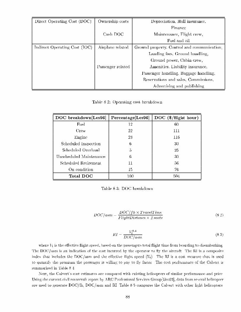
Direct Operating Cost (DOC) Ownership costs Depreciation, Hull insurance,
Finance
Cash DOC Maintenance, Flight crew,
Fuel and oil
Indirect Operating Cost (IOC) Airplane related Ground property, Control and communication,
Landing fees, Ground handling,
Ground power, Cabin crew,...
Passenger related Amenities, Liability insurance,
Passenger handling, Baggage handling,
Reservations and sales, Commissions,
Advertising and publishing
Table 8.2: Operating cost breakdown.
DOC breakdown[Les96] Percentage[Les96] DOC ($/ ight hour)
Fuel 12 60
Crew 22 111
Engine 23 116
Scheduled Inspection 6 30
Scheduled Overhaul 5 25
Unscheduled Maintenance 6 30
Scheduled Retirement 11 56
On condition 15 76
Total DOC 100 504
Table 8.3: DOC breakdown.
DOC=asm =DOC=fh� TravelT ime
F lightDistance�#seats(8.2)
RI =V 0:4b
DOC=asm(8.3)
where Vb is the e�ective ight speed, based on the passengers total ight time from boarding to disembarking.
The DOC/asm is an indication of the cost incurred by the operator to y the aircraft. The RI is a composite
index that includes the DOC/asm and the e�ective ight speed (Vb). The RI is a cost measure that is used
to quantify the premium the passenger is willing to pay to y faster. The cost performance of the Calvert is
summarized in Table 8.4.
Next, the Calvert's cost estimates are compared with existing helicopters of similar performance and price.
Using the current civil rotorcraft report by ARC Professional Services Group[Gro93], data from several helicopter
are used to generate DOC/fh, DOC/asm and RI. Table 8.5 compares the Calvert with other light helicopters.
88

Purchase Cost (in Million $) 1.84
DOC/fh (in $) 504
DOC/asm (in $) 0.604
RI 16.65
Table 8.4: Cost analysis summary.
Parameter Calvert Bell 206 MD500E AS 350D AStar BO-105CBS
Gross Weight (kg) 2298.7 1454 1362 1954 2505
# seats 4 5-6 4 5-6 5-6
# of engine(s) 2 1 1 1 2
Vcr (knots) 180 115 135 125 110
Range (nm) 540 369 228 416 310
Price ($M) 1.84 0.66 (1993 $) 0.675 (1993 $) 0.75 (1993 $) 1.9 (1993 $)
DOC/fh ($) 504 187 203 228 510
DOC/asm ($) 0.604 0.32 0.37 0.36 0.92
RI 16.65 26.3 23.95 24.18 8.96
Table 8.5: Performance and cost comparison.
Note that the Bell 206, MD500E and AS 350D Astar are single engine helicopters and have been produced in
large numbers. The only comparable helicopter is the BO-105CBS which is a twin engined helicopter. The
Calvert's purchase price estimate ($1.84M) is for the RFP requirement of 300 aircraft at the rate of 60 per year.
This price will come down if the production quantity and production rate are increased. Moreover, the price
quoted for the Bell 206, MD500E, AS 350D Astar and the BO-105 are in 1993 US $ [Gro93] and hence must be
corrected for in ation.
From Table 8.5, we conclude that the high performance of the aircraft has a downside. The Calvert DOC/fh,
DOC/asm and Rentability Index are not favorable compared to the single engined Bell 206, MD 500E and the
AS350D AStar. However all these aircraft have comparatively lower cruise speed and range compared to the
Calvert. Also the Calvert has two engines which is important for ight safety. On the other hand, the only other
twin engine aircraft of the table, the BO-105CBS, has roughly the same take o� weight and initial purchase cost
as the Calvert. The BO 105CBS o�ers 5-6 seats but is not able to y at 180 knots over 540 nm. The Calvert
trades two passengers for fuel and high speed devices. But because it has been designed with a cabin capacity
to �t 6 passengers, it can meet the performance of the BO 105CBS, whereas the BO 105CBS cannot operate as
a high speed helicopter.
Note that the above economic model has several limitations. In the present analysis, the e�ects of production
rate and total production quantity are included on the purchase price of the aircraft but they also in uence
maintenance and operating cost. Similarly, e�ects of automated manufacturing and quality control techniques
(specially for composites) are not captured by the model, since the model is based on historical data. Finally,
software development cost have to be added to this model, specially for an aircraft incorporating a glass cockpit
which requires multi-function displays. However, due to lack of more accurate historical data, this cost model is
used as a �rst approximation.
89

9 Alternate Flight Modes
In chapters 1 through 8 we describe how the Calvert is designed to meet the RFP performance requirements
(180 knots, 540 nm) with a total of 4 passengers (including pilot). However we provide the Calvert with 6
seats. The reason being that we want the Calvert to be a multi-purpose, multi-mission aircraft. Because
production quantity is what ultimately drives cost a versatile aircraft with good mission adaptability is of
paramount importance. Since the Calvert has a maximum seating capacity of 6 passengers it can operate in
several alternate ight modes.
9.1 6-passenger maximum cruise speed
For the 6-passenger mode the Calvert's empty weight and fuel weight are the same as the baseline 4-passenger
mode. However due to the extra two passengers the aircraft gross weight is increased by 190 kg. Therefore the
rotor stall limits are reached at a lower forward speed. For the 6-passenger mode the stall limit is encountered
at 190 knots as opposed to 210 knots for the baseline 4-seater mode. Therefore the never exceed speed for the
6-passenger mode is 190 knots. A safety margin of 30 knots is maintained to account for unexpected ight
conditions like turbulence/bad weather or high speed maneuvers. Therefore the cruise speed for the 6-passenger
mode is set at 160 knots (85% of never exceed speed).
9.2 6-passenger maximum range
In this mode the Calvert cruises at 142 knots with 6 passengers. The cruise speed of 142 knots is selected to
maximize the mission range. For this particular ight condition the Calvert can travel a distance of 580 nm
which exceeds the RFP range requirements of 540 nm.
9.3 Maximum payload mode
Without any modi�cation the Calvert (with a single pilot) can y up to 75 Knots at 4000 ft ISA with an
external payload of 3050 lbs over a range of 200 nm. This mode of operation is suited for logging and external
heavy lift operations similar to the K1200 (K-MAX). The Calvert's propeller consumes approximately 147 HP
in hover and does not contribute to it's lifting capability. By declutching the propeller, the Calvert can lift
4027 lbs of external load at 75 knots over 200 nm at 4000 ft ISA. The performance of the Calvert with a
declutching system is comparable to the K-MAX which can lift 6000 lbs of external load over 269 nm. The
Calvert's synchropter con�guration and its powerful engines (sized for high speed cruise), allow it, with only
slight modi�cation (declutching system), to perform heavy lifting operations.
9.4 Surveillance/search and rescue
The Calvert is well suited for Surveillance or SAR modes due to its e�cient hovering capability coupled with its
high speed cruise (180 knots) and high speed dash (210 knots) capability. The endurance limit of the Calvert
with 4-passengers (380 kg payload) and 6-passengers (570 kg) is 4.6 hours and 4.4 hours respectively.
9.5 Performance comparison
The Calvert is primarily designed for high speed cruise at 180 knots with 4 passengers. However the 6-passenger
(max. speed) mode o�ers some substantial advantages over the 4-passenger ight mode. Table 9.1 compares the
90

performance and cost for the Calvert's 4-passenger and 6-passenger ight modes with existing light helicopters
[Gro93]. The performance and cost calculation for the Calvert was carried out using the methodology described
in chapter 6.
Property Units Calvert Calvert Bell 206 MD500E B0-105CBS
(4-pass.) (6-pass.)
Cruise speed knots 180 160 115 135 110
# seats 4 6 5-6 4 5-6
# of engines 2 2 1 1 2
Gross weight kg 2298.7 2488.7 1454 1362 2505
Range nm 548 552 369 228 310
Purchase price M$ 1.84 1.84 0.66 (1993 $) 0.67 (1993 $) 1.9 (1993 $)
DOC/asm $ 0.6 0.39 0.32 0.37 0.92
RI 16.65 24.65 26.3 23.95 8.96
Table 9.1: Comparison of the Calvert's four and six passenger ight modes.
Table 9.1 indicates that the Rentability Index (RI) and Direct Operating Cost per air-seat-mile (DOC/asm)
of the Calvert (6-passenger) mode is comparable to the Bell 206 and MD500E helicopters and superior to the
Calvert (4-passenger) mode and the BO 105. However the cruise speed of the Calvert (4-passenger) mode is 13%,
33%, 56% and 63% higher than the Calvert (6-passenger) mode, Bell 206, MD 500E and BO 105 respectively.
From the point of view of the operator, the Calvert (4-passenger) mode provides the unique capability of
180 knots cruise at the cost of a 53% increase in DOC/asm and a 32% reduction in the RI with respect to the
Calvert (6-passenger) mode. The �nal choice of operation (4-passenger/6-passenger civil transport, Search and
Rescue, Surveillance, logging) rests with the user. Our design philosophy has been to provide the Calvert with
the mission exibility required to allow the mass production of one platform that can ful�ll many missions.
10 Summary and Conclusions
The RFP provided the challenging requirement of designing a helicopter that has much higher speed and
range capabilities than those of existing helicopters, but which should not cost more than these machines. As
outlined in chapter 2, a wide variety of con�gurations were evaluated to determine the optimal design. The
tradeo� study indicated that, from the point of view of cost and risk, a compound helicopter was an a�ordable
design with minimum technological risks.
The Calvert is a thrust and lift compounded synchropter. The thrust and lift o�-loading of the main rotor
improves high speed cruise e�ciency and delays the onset of retreating blade stall. This enables the Calvert to
meet the RFP performance requirement of 180 knots cruise. The intermeshing rotors eliminate the need for an
anti-torque system and provide a compact design. The twin two bladed composite rotors use active vibration
control for a smooth ride. The teetering hub is very compact, simple, and has low drag. The propeller is also
composite and is driven from the second stage of the transmission, which increases the transmission life. The
transmission design is unique; it is compact and provides high e�ciency at only a moderate weight penalty. The
fuselage layout, rotor design, landing gear, and the use of thrust and lift compounding all contributed to make
the Calvert a viable con�guration for a 180 knot cruise requirement. Drag reduction was critical to the overall
success of the design. Low drag is achieved by using retractable landing gear, a streamlined body, and extensive
rotor treatment, fairings, hub cap, etc. The Calvert can carry 4 people for 548 nm at a cruise speed of 180 knots.
91

Alternatively, it can carry 6 people for 552 nm at 160 knots or 6 people for 580 nm at 142 knots. The design is
powered by two variable speed 656 HP engines specially developed for this design. It can hover OGE at 17000
ft in ISA+20 conditions.
Since the goal was to have a purchase price equal to that of existing helicopters, cost needed to be attacked
with innovative designs and manufacturing technology. This has been achieved by merging proven technology,
repackaged in a unique manner, with innovative design, manufacturing, and supportability concepts. Three
proven helicopter con�gurations, synchropter, lift compounding (via wing) and thrust compounding (via pro-
peller), were combined to yield the lightest, least expensive con�guration. The wing generates 40% of the required
lift in cruise, thus providing su�cient separation between the 180 knots operating condition and the rotor stall
boundary. Not only is the rotor generating 60% of the lift, but is also providing su�cient control authority that
the wing could be of simpli�ed design (no aps, spoilers, or ailerons). The propeller provides 80% of the required
thrust in cruise. This reduces the rotor shaft forward tilt and allows the fuselage to remain level in high speed
forward ight, thereby greatly reducing the drag and improving cruise e�ciency. The combination of lift and
thrust compounding together with the synchropter con�guration results in a low vibration intrusion index that
is within the ADS-27 limits up to 160 knots. At the cruise speed of 180 knots, the Calvert marginally exceeds
the ADS-27 limits. This can be recti�ed with the use of passive isolators or the active trailing-edge aps on the
rotor blades.
Signi�cant innovation was included in the subsystems. New technologies were included without a�ecting
the validity of the basic design. The prognostics and health maintenance (PHM) system, engine FADEC, active
vibration control for the blades, in- ight blade tracking, active interior noise control, and advanced transmission
and oil cooler are all proposed technological innovations that will enhance various aspects of the helicopter
performance, such as reduced maintenance, improved safety, improved comfort, and reduced weight and cost.
To minimize cost, computerization and optimization are proposed for cost e�ective manufacturability, reliability
and maintainability. Computer Aided Design (CAD) can optimize parts for weight and strength and the output
of these computerized drawings can be sent directly to the shop oor. Computer controlled NC machines, tape
layers, �lament winders, rolling presses, etc will produce parts with repeatable accuracy.
Future capabilities of the Calvert can include a helicopter only version by removing the lift and thrust
compounding. This would reduce costs for the slow speed version of the Calvert. The Calvert is designed to
perform fast long range transportation at the same cost as existing helicopters in its class. The use of innovative
con�gurations, design and manufacturing processes, and advanced technology features ensures a safe, fast, smooth
and quiet helicopter.
92

Bibliography
[BB91] D. Balmford and B. Benger. The compound helicopter - a concept revisited. In 17th European
Rotorcraft Forum, Berlin, September 1991.
[Bel97] Bell Helicopter Textron, Ft. Worth, TX. Bell 430: Product data, 1997.
[BH40] D. Biermann and E. P. Hartman. Wind-tunnel tests of four and six blade single- and dual-rotating
propellers. NACA Report 747, NACA, 1940.
[Bha98] M. R. Bhagwat. On the relationship between rotor blade lift and tip vortex characteristics. Master's
thesis, Department of aerospace engineering, University of Maryland, College Park, 1998.
[BLN99] W. Baer, R. Lally, and G. Nickerson. An open wireless smart sensor architecture for JSF propulsion
and airframe PHM management. 55th Annual Forum Proceedings, American Helicopter Society,
Montreal, Canada, May 1999.
[Cor79] G. Corning. Supersonic and Subsonic, CTOL and VTOL, Airplane Design. Kensington, MD, 1979.
[CS93] W. F. Chana and T. Sullivan. The tilt wing design for a family of high speed VSTOL aircraft. In
49th Annual Forum Report Proceedings. American Helicopter Society, St. Louis, May 1993.
[Cur88] N. S. Currey. Aircraft Landing Gear Design : Principles and Practices. American Institute of
Aeronautics and Astronautics, Washington, D.C., 1988.
[dBF82] Gary deSimone, R. S. Blauch, and R. A. Fisher. The impact of missions on the preliminary design of
an ABC rotor. In 41st Annual International Conference of the Society of Allied Weight Engineers,
Inc. Society of Allied Weight Engineers, May 1982.
[Dow97] Dowty. Advanced Technology Propellers. Dowty Aerospace Propellers, Gloucester, England, 1997.
Issue 5.
[Dud84] D. Dudley. Handbook of Practical Gear Design. McGraw-Hill Cook Company, New York, 1984.
[Dye91] S. Dyess. Drive system weight optimization. Technical Report 2034, Society of Allied Weight
Engineers, May 1991.
[EC99] J. Epps and I. Chopra. Development of an sma actuated trim tab for in- ight rotor blade tracking.
In 40th AIAA/ASME/AHS/ASCE Structures, Structural Dynamics and Materials Conference, St.
Louis, Missouri, April 16-18 1999.
[EDZSG98] M. Essawy, S. Diwakar, S. Zein-Sabatto, and A. Garga. Fault diagnosis of helicopter gearboxes using
neuro-fuzzy techniques. In Proceedings of the 52nd Meeting of the MFPT Society, pages 293{302,
April 1998.
[GJP+89] B. Gmelin, A. Jones, J. Philippe, U. Schmidt, D. Humpherson, A. Rauen, and J. Stevens. Pre-
liminary comparisons of tiltrotor and compound helicopters for civil applications. In 45th Annual
Forum Proceedings, pages 815{828. American Helicopter Society, Boston, Mass., May 1989.
[Gro93] ARC Professional Services Group. Current civil rotorcraft:1992. 1993.
[HB93] G. Heath and R. Bossler, Jr. Advanced rotorcraft transmission (ART) program - �nal report. NASA
Contractor Report CR-191057, NASA, 1993.
[JDL96] V. Jammu, K. Danai, and D. Lewicki. Model-based sensor location selection for helicopter gearbox
monitoring. NASA Technical Memorandum TM-107219, NASA, May 1996.
93

[JHB93] T. Jordan, D. Humpherson, and B. Benger. The compound helicopter - the rotorcraft of the 21st
century. In 49th Annual Forum Proceedings. American Helicopter Society, St. Louis, Missouri, May
1993.
[Kis78] J. Kish. Advanced overrunning clutch technology. Technical Report 781039, SAE, November 1978.
[Kis93] J. Kish. Sikorsky aircraft advanced rotorcraft transmission (ART) program - �nal report. NASA
Contractor Report CR-191079, NASA, March 1993.
[KP98] J. Kiddy and D. Pines. Eigenstructure assignment technique for damage detection in rotating
structures. AIAA Journal, 36(9):1680{1685, September 1998.
[KS84] C.N. Keys and W.Z. Stepniewski. Rotary-Wing Aerodynamics. Dover, Mineola, NY, 1984.
[LC99] T. Lee and I. Chopra. Design and spin testing of an active trailing-edge ap actuated with piezo-
stacks. In 40th AIAA/ASME/AHS/ASCE Structures, Structural Dynamics and Materials Confer-
ence, St. Louis, Missouri, April 16-18 1999.
[Les96] P. Leslie. Short haul civil tiltrotor and Bell model 412 cost drivers. In Rotorcraft Economics
Workshop, Mo�et Field, CA, 1996. NASA Ames Research Center.
[LFYOP96] J. Lopez, I. Farber-Yeldman, K. Oliver, and M. Protz. Hierarchical neural networks for improved
fault detection using multiple sensors. In 52nd Annual Forum Proceedings, pages 1752{1758. Amer-
ican Helicopter Society, Washington, D.C., June 1996.
[Low92] M. Lowson. Progress towards quieter civil helicopters. Aeronautical Journal, June/July 1992.
[LP97] K. Lakshmanan and D. Pines. Detecting crack size and location in composite rotorcraft exbeams.
In Smart Structures and Materials 1997, Smart Structures and Integrated Systems, volume 3041,
March 1997.
[Mcg75] R. J. Mcghee. Low speed aerodynamic characteristics of a 13% thick airfoil section designed for
general aviation applications. Technical Memorandum 72697, NASA, NASA Scienti�c and Technical
Information Facility, P.O.Box 33, College Park, MD 20740, 1975.
[Mil97] J. Milgram. A comprehensive aeroelastic analysis of helicopter main rotors with trailing-edge aps.
PhD thesis, Department of aerospace engineering, University of Maryland, College Park, 1997.
[Nel44] C.W. Nelson. Airplane Propeller Principles. John Wiley & Sons, Inc., Ames, IA, 1944.
[OG97] C. Orkin and M. Gustafson, Jr. K-max intermeshing rotor drive system. In 53rd Annual Forum
Proceedings, pages 1554{1568. American Helicopter Society, Virginia Beach, May 1997.
[Ols93] J. R. Olson. Reducing helicopter operating costs. Verticraft, January/February 1993.
[PLP98] A. Purekar, K. Lakshmanan, and D. Pines. Detecting delamination damage in composite rotorcraft
exbeams using the local wave response. In Smart Structures and Materials 1998, Smart Structures
and Integrated Systems, volume 3329, March 1998.
[R.90] Prouty R. Rotary-Wing Performance, Stability and Control. Robert E. Krieger Publishing Company,
Malabar, FL, 1990.
[Ray92] D. P. Raymer. Aircraft Design: A Conceptual Approach. American Institute of Aeronautics and
Astronautics, Washington, DC, 1992.
[RB93] J. W. Rutherford and S. M. Bass. The design evolution of the canard rotor/wing. In AHS 49th
Annual Forum Proceedings. American Helicopter Society, May 1993.
94

[RT86] D. Reisdorfer and M. L. Thomas. Static test and ight test of the Army/Bell ACAP helicopter. In
42nd Annual Forum Proceedings, pages 865{872. American Helicopter Society, Washington, D.C.,
June 1986.
[SC99] M. Spencer and I. Chopra. Neurocontrol of simulated full scale rotor vibrations using trailing-edge
aps. In 40th AIAA/ASME/AHS/ASCE Structures, Structural Dynamics and Materials Confer-
ence, St. Louis, Missouri, April 16-18 1999.
[Sch76] A. Schmidt. A method for estimating the weight of aircraft transmissions. Technical Report 1120,
Society of Allied Weight Engineers, May 1976.
[Sco96] M. W. Scott. Economic analysis of SHCT tiltrotor. In NASA/Industry/Operator Rotorcraft Eco-
nomics Workshop. NASA Ames Research Center, May 1996.
[Sel99] 1999. Website: http://amber.aae.uiuc.edu/ m-selig/ads/coord database.html, UIUC Airfoil Coor-
dinates and Performance Database, 1999.
[SP99] P. Samuel and D. Pines. Fault classi�cation in a helicopter gearbox using a normalized energy metric.
In 40th AIAA/ASME/AHS/ASCE Structures, Structural Dynamics and Materials Conference, St.
Louis, Missouri, April 16-18 1999.
[SPL98] P. Samuel, D. Pines, and D. Lewicki. A comparison of stationary and non-stationary transforms for
early fault detection in the OH-58A main transmission. In 54th Annual Forum Proceedings, pages
867{887. American Helicopter Society, Washington, D.C., May 1998.
[SPT98] P. Samuel, D. Pines, and A. Twarowski. Unpublished proprietary research, Alfred Gessow Rotorcraft
Center, University of Maryland, College Park and the Rockwell Science Center, 1998.
[SS83] W. Z. Stepniewski and R. A. Shinn. A comparative study of Soviet vs western helicopters, part 2:
Evaluation of weight, maintainability, and design aspects of major components. NASA Contractor
Report 3580, NASA, 1983.
[Tal91] P. D. Talbot. High speed rotorcraft: Comparison of leading concepts and technology needs. In 47th
Annual Forum Proceedings. American Helicopter Society, Phoenix, AZ 1991.
[TNC99] M. N. Tishchenko, V. T. Nagaraj, and I. Chopra. Unmanned transport helicopter. In 55th Annual
Forum Proceedings. American Helicopter Society, Montreal, Canada, May 1999.
[US84] D. K. Unsworth and J. G. Sutton. An assessment of the impact of technology on VTOL weight pre-
diction. In 40th Annual Forum Proceedings, pages 263{284. American Helicopter Society, Arlington,
Virginia, May 1984.
[Vui90] A. Vuillet. Rotor and blade aerodynamic design. Technical Report 781, AGARD, Advisory Group
For Aerospace Research And Development, NATO, April 1990. pp. 3-1 to 3-59.
[Whi98] G. White. Design study of a split-torque helicopter transmission. In Proceedings of the Institution
of Mechanical Engineers, Part G: Journal of Aerospace Engineering, volume 212(2), 1998.
[Yeo99] H. S. Yeo. A comprehensive vibration analysis of a coupled rotor/fuselage system. PhD thesis,
Department of aerospace engineering, University of Maryland, College Park, 1999.
[YGS87] L. Young, D. Grahm, and R. Straub. Reduction of hub- and pylon-fairing drag. In 43rd Annual
Forum Proceedings, pages 323{344. American Helicopter Society, St. Louis, Missouri, May 1987.
95
MIL-STD-1374 PART I - TAB PAGE 1
NAME UMD MODEL CALVERT
DATE JUNE 27 1999 REPORT
GROUP WEIGHT STATEMENT
AIRCRAFT
(INCLUDING ROTORCRAFT)
ESTIMATED - CALCULATED - ACTUAL
(CROSS OUT THOSE NOT APPLICABLE)
CONTRACT NO. N/A
AIRCRAFT, GOVERNMENT NO. N/A
AIRCRAFT, CONTRACTOR NO. N/A
MANUFACTURED BY N/A
MAIN AUXENGINE QUANTITY 2ENGINE MANUFACTURED BY N/AENGINE MODEL N/AENGINE TYPE N/A
PROPELLER QUANTITY 1PROPELLER MANUFACTURED BY N/APROPELLER MODEL N/A
PAGES REMOVED NONE PAGE NO.
96

MIL-STD-1374 PART I - TAB GROUP WEIGHT STATEMENT (KG) PAGE 2
NAME UMD WEIGHT EMPTY MODEL CALVERT
DATE JUNE 27 1999 REPORT
1 WING GROUP WINGLETS GLOVE / LEX WING
2 TOTAL 22.33 BASIC STRUCTURE4 CENTER SECTION5 INTERMEDIATE PANEL6 OUTER PANEL7 SECONDARY STRUCTURE8 AILERONS / ELEVONS9 SPOILERS
10 FLAPS - TRAILING EDGE11 - LEADING EDGE12 SLATS131415 ROTOR GROUP 147.416 BLADE ASSEMBLY 94.2017 HUB & HINGE 53.201819 EMPENNAGE GROUP CANARD HORIZ. STAB. VERTICAL FIN VENTRAL FIN TAIL ROTOR
20 TOTAL 7 3.40 10.421 BASIC STRUCTURE22 SECONDARY STRUCTURE23 CONTROL SURFACES24 ( INCL. BALANCE WEIGHTS ) ( ) ( ) ( )25 BLADES26 HUB & HINGE27 ROTOR / FAN DUCT & ROTOR SUPTS282930 FUSELAGE GROUP FUS. / HULL BOOMS
31 TOTAL 176.832 BASIC STRUCTURE33 SECONDARY STRUCTURE34 ENCLOSURES, FLOORING, ETC.35 DOORS, RAMPS, PANELS & MISC.363738 ALIGHTING GEAR GROUP TRICYCLE MAIN NOSE / TAIL ARR. GEAR CAT. GEAR
39 TOTAL 71.70 17.30 8940 RUNNING GEAR / FLOATS / SKIS41 STRUCTURE42 CONTROLS434445 ENGINE SECTION OR NACELLE GROUP AUXILIARY ENGINES MAIN ENGINES
46 LOCATION **47 TOTAL - EACH LOCATION 3948495051 AIR INDUCTION GROUP AUXILIARY ENGINES MAIN ENGINES
52 LOCATION **53 TOTAL - EACH LOCATION 3.654 INLETS55 DUCTS, ETC.5657 TOTAL STRUCTURE 488.5
* LANDING GEAR "TYPE": INSERT "TRICYCLE", "TAIL WHEEL", "BICYCLE", "QUADRICYCLE", OR SIMILAR DESCRIPTIVE NOMENCLATURE.
** WING, FUSELAGE, ETC.
97
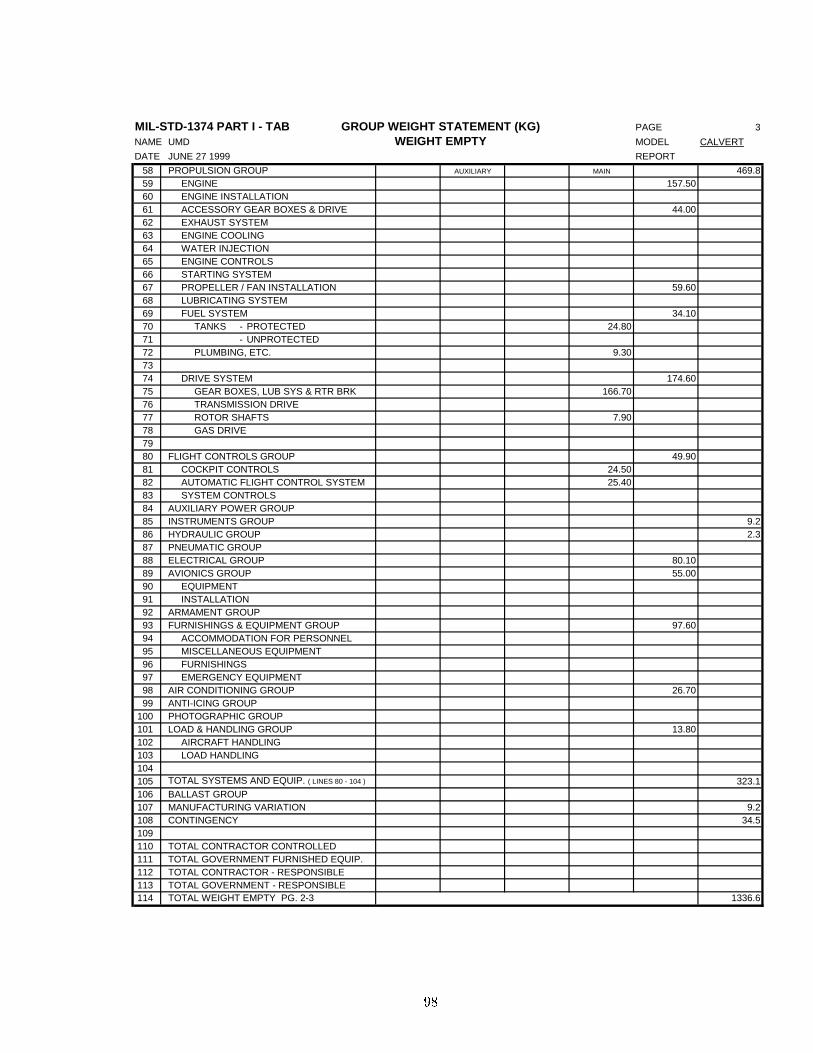
MIL-STD-1374 PART I - TAB GROUP WEIGHT STATEMENT (KG) PAGE 3
NAME UMD WEIGHT EMPTY MODEL CALVERT
DATE JUNE 27 1999 REPORT
58 PROPULSION GROUP AUXILIARY MAIN 469.859 ENGINE 157.5060 ENGINE INSTALLATION61 ACCESSORY GEAR BOXES & DRIVE 44.0062 EXHAUST SYSTEM63 ENGINE COOLING64 WATER INJECTION65 ENGINE CONTROLS66 STARTING SYSTEM67 PROPELLER / FAN INSTALLATION 59.6068 LUBRICATING SYSTEM69 FUEL SYSTEM 34.1070 TANKS - PROTECTED 24.8071 - UNPROTECTED72 PLUMBING, ETC. 9.307374 DRIVE SYSTEM 174.6075 GEAR BOXES, LUB SYS & RTR BRK 166.7076 TRANSMISSION DRIVE77 ROTOR SHAFTS 7.9078 GAS DRIVE7980 FLIGHT CONTROLS GROUP 49.9081 COCKPIT CONTROLS 24.5082 AUTOMATIC FLIGHT CONTROL SYSTEM 25.4083 SYSTEM CONTROLS84 AUXILIARY POWER GROUP85 INSTRUMENTS GROUP 9.286 HYDRAULIC GROUP 2.387 PNEUMATIC GROUP88 ELECTRICAL GROUP 80.1089 AVIONICS GROUP 55.0090 EQUIPMENT91 INSTALLATION92 ARMAMENT GROUP93 FURNISHINGS & EQUIPMENT GROUP 97.6094 ACCOMMODATION FOR PERSONNEL95 MISCELLANEOUS EQUIPMENT96 FURNISHINGS97 EMERGENCY EQUIPMENT98 AIR CONDITIONING GROUP 26.7099 ANTI-ICING GROUP
100 PHOTOGRAPHIC GROUP101 LOAD & HANDLING GROUP 13.80102 AIRCRAFT HANDLING103 LOAD HANDLING104105 TOTAL SYSTEMS AND EQUIP. ( LINES 80 - 104 ) 323.1106 BALLAST GROUP107 MANUFACTURING VARIATION 9.2108 CONTINGENCY 34.5109110 TOTAL CONTRACTOR CONTROLLED111 TOTAL GOVERNMENT FURNISHED EQUIP.112 TOTAL CONTRACTOR - RESPONSIBLE113 TOTAL GOVERNMENT - RESPONSIBLE114 TOTAL WEIGHT EMPTY PG. 2-3 1336.6
98

MIL-STD-1374 PART I - TAB GROUP WEIGHT STATEMENT (KG) PAGE 4
NAME UMD USEFUL LOAD AND GROSS WEIGHT MODEL CALVERT
DATE JUNE 27 1999 REPORT
115 LOAD CONDITION PRIMARY116117 WEIGHT EMPTY 1336.6118 CREW ( QTY _ 0 )119 UNUSABLE FUEL120 OIL121 TRAPPED122 ENGINE 12123 TRANSMISSION 10.5124 AUX. FUEL TANKS QTY
125 INTERNAL126 EXTERNAL127128 WATER INJECTION FLUID129 BAGGAGE 80130 GUN INSTALLATIONS131 GUNS LOC FIX. OR FLEX. QTY CAL.
132133134 SUPPORTS *135 WEAPONS PROVISIONS **136137138139140 CHAFF ( QTY _________ )
141 FLARES ( QTY _________ )
142143144 SURVIVAL KITS145 LIFE RAFTS146 OXYGEN147148149150 OPERATING WEIGHT151 PASSENGERS 300152153 CARGO154155 AMMUNITION QTY CAL.
156157158 WEAPONS **159160161162163164 ZERO FUEL WEIGHT165 USABLE FUEL TYPE LOC GALS 559.6166 INTERNAL167168 EXTERNAL169170 TOTAL USEFUL LOAD 962.1171 GROSS WEIGHT 2298.7
* IF REMOVABLE AND SPECIFIED AS USEFUL LOAD.
** LIST STORES, MISSILES, SONOBUOYS, ETC. AND PYLONS, RACKS, LAUNCHERS, CHUTES, ETC. THAT ARE NOT PART OF WEIGHT EMPTY. LIST NOMENCLATURE,
LOCATION, AND QUANTITY FOR ALL ITEMS SHOWN INCLUDING INSTALLATION.
99


![Engineering Notes - aancl.snu.ac.kraancl.snu.ac.kr/aancl/research/International Journal/[2008] Jiyoung... · the Korean BERP (British Experimental Rotor Program) blade (KBERP) and](https://img.pdfslide.us/doc/110x75/5b33445a7f8b9aa0238ce71d/engineering-notes-aanclsnuac-journal2008-jiyoung-the-korean-berp.jpg)