Embed Size (px)
Citation preview

Permanent Way
Catch Pit Lids 15
RidgidrainTM 16 - Structured Wall Pipes and Seals
- Couplings
WeholiteTM 17 - Structured-Wall Pipe
Heavy Duty Solid Wall PE Pipe 18 - Pads No. PA05/02084
Polyvault ChambersTM 18
MULTIductTM 19 - for UTX/URX Systems
RAILductTM 20
GRPTM 20 - Cable Troughing and Trays
Cable Protection Troughs 21 - Straights, Transitions, Curves and Tees
Trough-LiteTM 24 - Lightweight cable protection troughs
Concrete CanvasTM 25
Concrete CanvasTM Material Data 27
Ballast Mats 28
Sleeper Pads 28
TerramTM 6 - Hydrotex 2.0
- PW-NP-1.0 Geotextile | PW2.0 Robust Geotextile
- PW4.0-LA Reinforcement Composite | PW5.0 Radar
Detectable Geotextile
- PW9 Robust Separator
- Terram 3000 and 4000
- Guidelines for the use of Geosynthetics in Rail Construction
GeowebTM 11
TensarTM 12
- TriAx® TX190L Geogrid
Polypipe 13 - Structured Wall Catchpits
CubisTM 14
- Cubis Drainage Catch Pits
STAKKAboxTM 14
- Ultima Access Chambers
Drainage Catch Pits 15 - Precast Concrete
5

RAIL I PERMANENT WAY 7RAIL I PERMANENT WAY6
Permanent WayPermanent Way
TerramTM
Hydrotex 2.0 – Pads No. 057/100401 and 057/100405TerramTM
PW-NP-1.0 Geotextile | PW2.0 Robust Geotextile
Mechanical Properties (Mean values)
Wide-width strip tensile - Mean peak strength - Elongation at peak strength
EN ISO 10319kN/m
%
95
75
CBR Puncture Resistance - Mean peak strength EN ISO 12236 kN 18
Cone Drop - Mean hole diameter EN 13433 mm 0
Filter Properties
Pore Size – Mean AOS ASTM F315-03 μm <1
Permeability - VI 280 - 0.28m Head
EN ISO 11058 l/m2s 0.03
Physical Properties (Typical values)
Weathering - Retained strength at 200MJ/m2 exposure EN 12224 % >90
Microbiological resistance - Retained strength EN 12225 % No loss
Resistance to acids and alkalis - Retained strength EN 14030 % No loss
Oxidation - Retained strength at 85 days EN 12225 % >90
HYDROTEX 2.0 product acceptance certificate PA05/05451Hydrotex provides a permanent way solution for trackbed stability that acts as a filter / separator for fine soils and also removes the need for sandblankets.
TERRAMTM PW-NP-1.0 is approved by Network Rail – Cat No 57/100776PW-NP-1.0 – Trackbed filter / separator between ballast and subgrade.
TERRAMTM PW2.0 product acceptance certificate - 57/100777PW2.0 Geocomposite - a robust separator / filter incorporating a drainage net between two geotextile filter layers.
Features:
Prevents upwards particle passage smaller than 0.002mm
Permeable filter, allowing upward and downward water transmission
Replaces the requirement for a sand blanket
Quickly and easily installed, no specialist plant is required
Functions under ballast without any reduction in performance
Residual slurry becomes desiccated as any pore water is dissipated
Supplied on standard rolls of 3.9m x 50m (other sizes available on request).
Uses:
Geotextile separator as per NR/SP/TRK/9039.
We also offer radar detectable geotextiles PW5 in rolls 4m x 50m PW Trace in rolls 0.5m x 200m.
Uses:
A drainage enhancing composite used in wet ground conditions
Robust separator that prolongs ballast life where poor drainage exists as per NR/SP/TRK/9039 treatment number 2.
TERRAMTM Hydrotex is strong but flexible allowing the composite to conform to the excavated formation, so that no voids exist below the filter media for the development of pockets of slurry resulting in an unstable trackbed.
Environmental benefits:
TERRAMTM Hydrotex composite reduces the depth of excavation that would be required with a sand blanket. The result is a decrease in the amount of spoil being taken away for landfill and a reduction of vehicles required to deliver materials.
Mechanical Properties (Mean values)
Wide-width strip tensile - Mean peak strength - Elongation at peak strength
EN ISO 10319 kN/m % 22 60
-2.2 ±30
CBR Puncture Resistance - Mean peak strength EN ISO 12236 kN 3.3 - 0.33
Cone Drop - Mean hole diameter EN 13433 mm 22 + 2.2
Hydraulic Properties
Pore Size – Mean AOS μm 60 ±30%
Permeability - VI H50 - 50mm Head
EN ISO 11058 l/m2.s 45 -30%
Physical Properties (Typical values)
Weathering - Retained strength at 200MJ/m2 exposure
EN 12224 % >90 n/a
Microbiological resistance - Retained strength EN 12225 % No loss n/a
Resistance to acids and alkalis - Retained strength EN 14030 % No loss n/a
Oxidation - Retained strength at 85 days EN 12225 % >90 n/a
Composition
Extruded polyethylene net with a geotextile filter bonded to both sides. The geotextile is manufactured from virgin polypropylene fibres
Mechanical Properties
Tensile Strength (MD) EN ISO 10319 kN/m 52.5 -5.25
CBR Puncture Resistance EN ISO 12236 N 9000 -0.9
Hydraulic Properties – PW2.0
In-plane Water Flow EN ISO 12958 l/m.s @20kPa 0.475 -0.05
Hydraulic gradient = 1.0, hard/hard l/m.s @100kPa 0.390 -0.04
Plattens and measured in the longitudinal l/m.s @200kPa 0.300 -0.03
Direction l/m.s @400kPa 0.180 -0.02
Hydraulic Properties – Geotextile
Opening Size EN ISO 12956 μm 60 ±18
Permeability EN ISO 11058 l/m2s 45 -9
Physical Properties (Typical values)
Mass per unit area EN ISO 9864 g/m2 1160 n/a
Thickness at 2kPa EN ISO 9863-1 mm 6.3 n/a
Roll Dimensions
Roll Width m 4.0
Roll Length m 25
Roll Weight kg
Mean Values
Mean Values
Applied Tolerance
Applied Tolerance
The information in this brochure is to the best of our knowledge true and accurate, but all recommendations or suggestions are made without guarantee. Since the conditions of use are beyond their control, Keyline disclaim any liability for loss or damage suffered from the use of these data or suggestions.
Furthermore no liability is accepted if use of any product in accordance with these data or suggestions infringes any patent. Keyline Rail reserve the right to change product specifications without further notification.

NEW
RAIL I PERMANENT WAY 9RAIL I PERMANENT WAY8
Permanent Way
TerramTM
PW4.0-LA Reinforcement Composite | PW5.0 Radar Detectable GeotextileTerramTM
PW9 Robust Separator
Mechanical Properties – Geotextile Test Method Unit
Tensile Strength kN/mMD 22 2.2
CMD 22 2.2
Tensile Elongation EN ISO 10319 %
MD 60 ±20
CMD 60 ±20
CBR Puncture Resistance EN ISO 12236 N 33 0.33
Cone Drop EN ISO 13433 mm *
Hydraulic Properties – Geotextile
Pore Size – Mean AOSEN ISO 11058
μ 75 ±20
Permeability – (H50) l/m2s 50 -15
Composition
TensarTM SSLA30 geogrid with a geotextile filter bonded to one side. Geotextile is manufactured from virgin polypropylene fibres.
Mechanical Properties (Mean values)
Wide-width strip tensile - Mean peak strength - Elongation at peak strength
EN ISO 10319 kN/m % 22 60
-2.2 ±30
CBR Puncture Resistance - Mean peak strength EN ISO 12236 kN 3.3 - 0.33
Cone Drop - Mean hole diameter EN 13433 mm 22 + 2.2
Hydraulic Properties
Pore Size – Mean AOS μm 60 ±30%
Permeability - VI H50 - 50mm Head
EN ISO 11058 l/m2.s 45 -30%
Physical Properties (Typical values)
Weathering - Retained strength at 200MJ/m2 exposure
EN 12224 % >90 n/a
Microbiological resistance - Retained strength EN 12225 % No loss n/a
Resistance to acids and alkalis - Retained strength EN 14030 % No loss n/a
Oxidation - Retained strength at 85 days EN 12225 % >90 n/a
Standard roll dimensions m 3.8 x 25 1.9 x 25
Mean Value (Applied Tolerance Value [a])
Test Method Unit PW9
4. Mechanical Properties
Tensile Strength EN ISO 10319 kN/m kN/m 52.5 (-5.25)
Tensile Elongation EN ISO 10319 % 60 (±20)
CBR Puncture Resistance EN ISO 12236 kN 9 (-0.9)
Cone Drop EN ISO 13433 mm 2 (+1)
5. Hydraulic Properties
Pore Size - Mean AOS EN ISO 12956 μm 60 (±20)
Permeability – (H50) EN ISO 11058 l/m2s 45 (-9)
Retained Strength [b]
Test Method Unit Terram PW9
6. Properties Relating to Durability
Weathering 50MJ/m2 exposure (1 month EU) EN 12224 % >90
Microbiological resistance EN 12225 % No loss
Resistance to acids and alkalis EN 14030 % No loss
Oxidation at 85 days (100 years) EN 12226 % >90
Test Method Unit
7. Physcial Properties (nominal)
Thickness @ 2kPa EN ISO 9863-1 mm 2.5
8. Material Dimensions
Standard Roll Length m 25
Standard Roll Width m 4.0
Maximum Roll Width m 6.0
Gross Roll Weight (nominal)[c] kg 130
TERRAMTM PW4.0-LA product acceptance certificate – 57/000779PW4.0-LA Geocomposite – comprising SSLA30 Geogrid and a Geotextile filter layer, enabling reinforcement and separation to be laid in one pass.
1. Description: Nonwoven geotextile manufactured from UV stabilised, high tenacity, virgin polypropylene fibres that have been both mechanically and thermally bonded to provide high strength and excellent abrasion characteristics.
2. Application: Terram PW9 filter/separator is designed to maintain separation between the adjacent sand/sub-grade and ballast layers within the trackbed construction, preventing the upward movement of fine sub-grade particles and the intermixing of ballast with the sub-base.
Terram PW9 is suitable for where sub-grade soils have sufficient strength and good filtration yet have a higher percentage of large particles (>10% by weight >14mm) present.
3. Features: Engineered to provide high strength and high elongation at break to ensure excellent resistance to damage during construction and under the dynamic loading applied within trackbed. Terram PW9 is manufactured to performance properties, not weight, sufficient fibre will be added to achieve these properties.
Manufactured from high tenacity UV stabilised virgin polypropylene fibres which have been heavily drawn to ensure excellent long term durability in all soil types.
Manufactured using a randomly orientated web to provide completely isotropic properties, ensuring that high strength is not limited to a single direction. Excellent uniformity with high permeability and low pore size for soil filtration.
9. Packaging and Identification: Terram PW9 is supplied on cardboard cores and wrapped in Polyethylene sheeting with identification labels in accordance with ISO 10320.
10. Storage: The rolls of geotextile shall be stored on stable/ level ground and stacked not more than five rolls high and no other materials shall be stacked on top. The rolls can be stored outdoors when packaged, but should be protected from exposure to UV. All materials should be stored in accordance with good health and safety practice and in accordance with local laws. For additional information please refer to Terram Geotextiles MSDS.
11. Notes: a. Reported values are arithmetic mean values unless otherwise stated. A set of test results shall be those results derived from specimens cut from one sample and taken across the full width of the roll. For sampling, EN ISO 9862 should be applied, i.e. samples should be taken not less than 5m from the end of the roll in machine direction and over the whole width in the cross machine direction. The location of the sample should be described exactly. Applied tolerances are based on 95% Confidence limits, this is the value below which not more than 5% of the test results may be expected to fall. This represents the value at 1.645 standard deviations below the mean value. For evaluation of conformance, statistical procedure should be used in line with section 5.2 of CEN/TR 15019: 2004. The tolerance value provided for tensile elongation is based on an absolute value; e.g. 60% ±20% = 40%-80%.
b. Reported values are based on durability testing on the lowest grade product within a family, no loss indicates that there is no notable effect due to exposure, laboratory sample variation may identify a small change in properties.
c. A nominal value indicates that the value is not part of the performance specification and is provided for guidance only.
d. Gross roll weight is based on 4.5m rolls at standard length, information provided is for lifting guidance only and does not for part of quality control.
12. Additional Information: Refer to the Terram Jointing Methods (downloadable from www.terram.com) for when simple overlaps are required for subsequent and adjacent roll lengths. However, pegging, sewing, stapling or gluing can also be used depending upon the application, the sub-grade conditions, the loading, the convenience and the cost. These figures relate to standard product weights and roll sizes. Other weights, sizes and colours may be available on request. For further information please contact Fiberweb Geosynthetics Technical Support.
TERRAMTM PW5.0Geosynthetic composite comprising a robust geotextile filter separator incorporating an electronically conductible radar detectable strip spaced at set intervals.
Uses:
Mechanical stabiliser/separator used in accordance with RT/CE/S/039.
Uses:
TerramTM PW5.0 has been specifically engineered for use below track ballast as a filter separator. It has the ability to provide an indication of the level of ballast contamination and movement, allowing for monitoring of trackbed distortion when used in conjunction within ground probing radar systems.
Mean Values
Mean
Applied Tolerance
Tolerance Value
Permanent Way
The information in this brochure is to the best of our knowledge true and accurate, but all recommendations or suggestions are made without guarantee. Since the conditions of use are beyond their control, Keyline disclaim any liability for loss or damage suffered from the use of these data or suggestions.
Furthermore no liability is accepted if use of any product in accordance with these data or suggestions infringes any patent. Keyline Rail reserve the right to change product specifications without further notification.

RAIL I PERMANENT WAY 11RAIL I PERMANENT WAY10
Permanent WayPermanent Way
TerramTM
Terram 3000 and 4000 – Pads No. 57/100706 and 57/100709
Product Grades
Mechanical Properties – Control
Wide width strip tensile EN ISO 10319
- Mean peak strength kN/m 8.0 18.0 22.0
- Elongation at peak strength
kN/m 28 33 33
CBR puncture resistance EN ISO 12236
- Mean peak strength N 1500 3250 4300
Mechanical Properties – Consequential
Wide width strip tensile EN ISO 10319
- strength at 5% strain kN/m 3.4 6.3 7.5
Hydraulic Properties – Consequential
Pore size EN ISO 12956
- Mean AOS O90 μm 150 100 85
Permeability
EN ISO 11058
- VIH50
- 5cm head 10-3m.s-1(I/m2.s) 100 55 45
Physical Properties – Typical
Mass per unit area EN 965 g/m2 125 260 335
Roll width m 4.5 4.5 4.5
Roll length m 100 100 50
Roll weight kg 65 125 80
PADS number 57/100704 57/100706 57/100709
1000 3000 4000
Uses:
Terram 3000 and 4000 are suitable for drainage and separation applications under RT/CE/S/010.
TerramTM
Guidelines for the use of Geosynthetics in Rail Construction
GeowebTM
The use of geogrids/geotextile in railway earthworks is covered by Network Rail Model Clause 52 for Specifying Civil Engineering Works and their product specification needs to comply with the requirements of NR/SP/TRK/010 (formerly RT/CE/S/010).
The following geotextiles listed are selected in accordance to comply with the technical criteria required that is outlined by the above Network Rail document to be used in either a drainage or separation application for use in track construction. All products have Network Rail Approval and are supplied with respective Catalogue numbers.
Drainage specification: < 40 l/m2.s permeability, 10kN tensile minimum, between 30 – 180 micron pore size, < 1500N CBR Puncture Resistance. Separator Specification: < 10 l/m2.s permeability, 10kN tensile minimum, 30 – 85 micron pore size, < 3000N CBR Puncture Resistance.
All the above products have full Network Rail approval for use in track and drainage applications across the UK network.
Geoweb® has been successfully used by Network Rail to stabilise the sub-ballast over soft soils and thus reduce sub-soil movement and consequently maintenance costs. The Geoweb® Cellular Confinement System has been successfully applied to strengthen the track structure over weak soils and stabilise soils on adjacent slope and channel embankments.
The engineered system uses a three-dimensional honeycomb-like structure that generates powerful confinement forces and soil to cell friction creating a load dispersion structure with a high flexural strength. This results in the long-term performance of the load support system and so reduces the rate of track geometry degradation and lowers maintenance costs.
A major problem in the rail industry is unstable soils. A major solution is the Geoweb® cellular confinement system. By significantly reducing vertical and lateral stresses, the Geoweb® system reduces and can even eliminate the cost of dealing with unstable soils. Long-term test results and successful applications worldwide confirm the benefits of the Geoweb® system.
The Stable Solution: Railway engineers worldwide have successfully applied cellular confinement technology to 1) strengthen the track structure over weak soils and 2) stabilise soils on adjacent slope and channel embankments. The engineered system uses a three-dimensional, honeycomb-like structure that confines soil in its cells so the
soil functions and performs as you intend it to. Geoweb® has been successfully engineered to stabilise infill materials for load support, slope and channel protection and earth retention applications.
Benefits in Load Support: In load support applications, the Geoweb® system generates powerful confinement forces and soil-to-cell wall friction creating a load dispersion structure with high flexural strength. The results, significant improvements in the long-term performance of the load support system. The proof, a reduction in the rate of track geometry degradation and measurable lower maintenance costs.
Geotextiles Suitable for Drainage Applications under NR/SP/TRK/010:
Terram 2000 – 4.5m x100m Cat No. 57/100705
Terram 3000 – 4.5m x 100m Cat No. 57/100706
Terram 4000 – 4.5m x 50m Cat No. 57/100709
Terram PW1 – 4m x 50m Cat No. 57/100776
Geosynthetics Suitable for Separator Applications under NR/SP/TRK/010:
Terram 3000 – 4.5m x 100m Cat No. 57/100706
Terram 4000 – 4.5m x 50m Cat No. 57/100709
Terram PW1 – 4m x 50m Cat No. 57/100776
Also for Separation under NR/SP/TRK/9039 (formerly) RT/CE/C/039
Code of Practice: Formation Treatments
Terram PW1 – 4m x 50m Cat No. 57/100776
Terram PW2 – 4m x 25m Cat No. 57/100775 – Robust Separator
Terram PW4LA – 3.8m x 25m Cat No. 57/100779 – Reinforced Separator
ALWAYS SPECIFYTHE GENUINE
GEOWEB® PRODUCT
The information in this brochure is to the best of our knowledge true and accurate, but all recommendations or suggestions are made without guarantee. Since the conditions of use are beyond their control, Keyline disclaim any liability for loss or damage suffered from the use of these data or suggestions.
Furthermore no liability is accepted if use of any product in accordance with these data or suggestions infringes any patent. Keyline Rail reserve the right to change product specifications without further notification.

RAIL I PERMANENT WAY 13RAIL I PERMANENT WAY12
Permanent WayPermanent Way
PolypipeStructured Wall Catchpits – Pads No. PA05/667
Polypipe’s bespoke structured wall catchpits are manufactured to customer’s exact requirements. Because they arrive on site as prefabricated units, they can be quickly installed and connected to your trackside drainage system.
Our catchpits are Parts and Drawing Systems (PADS) approved for their intended application.
Tailor Made Solutions As part of the unique fabrications service offered by Polypipe, fully qualified design engineers work in partnership with our customers to create a bespoke solution to match individual specifications and site requirements.
Seamless Integration Fabricated solutions from Polypipe are designed to integrate into an overall drainage application, with the fabricated element designed specifically to meet the requirements of the scheme. Polypipe offers a value engineered approach to bespoke fabrications and is supported by a technical department that provides sound advice and design experience. Our products can be designed and manufactured to suit any project timeline, without the need for lengthy lead times.
Off-site Construction Polypipe is unique in its position of being able to offer pre-fabricated, bespoke solutions constructed off-site. This approach to modern methods of construction reduces time and installation costs on-site as well as minimizing health and safety risks in handling, storage and installation. The strong, yet lightweight properties of plastic pipes also enables further reduction in the use of heavy plant on-site.
Key benefits:
Provides easy access maintenance points for silt collection
Bespoke, fully welded and watertight
Tough and durable
One piece installation
Off-site construction – delivered ready to install resulting in reduced installation time and on-site costs
Strong, yet lightweight, minimising Health and Safety risks in handling, storage and installation
Choice of diameters available 1050mm, 1200mm, 1500mm, 1800mm, 2100mm
Fully bespoke options of inlets and outlets
Inlets and outlets supplied with integral sockets as standard
Catchpits are also available perforated for use as a lightweight soakaway chamber
Depth can be tailored
Plastic or lockable steel cover
Step irons to BS 1247 now replaced by BS EN 13101
Ladder option available.
TensarTM
TriAx® TX190L Geogrid – Pads No. 57/100470
Geometrical Longitudinal Diagonal Transverse General
Rib pitch (mm) 60 60
Mid-rib depth (mm) 1.9 1.6
Mid-rib width (mm) 1.6 2.5
Nodal thickness (mm) 5.4
Rib shape Rectangular
Aperture shape Triangular
Open area aspect ratio (%) ≥85
Roll size 50m x 3.8m
Mechanical
Junction efficiency (%) 90
Typical isotropic stiffness ratio 0.60
Mean radial secant modulus at low strain (kN/m @ 0.5% strain) 600±65
Durability
Resistance of chemical degradation 96%
Resistance to weathering 98%
Resistance to oxidation 90%
Resistance to installation damage >87%
Roll size 50m x 3.8m
SSLA30 Large aperture Geogrid has been used for many years for undertrack applications under approval 57/100822.
With the advent of Triaxial geogrid technology this has now been replaced by TX190L. Whereas the tensile stiffness of biaxial geogrids is predominantly in two directions, with TriAx® it is now multi-directional. The product has near isotropic tensile properties, through 360°.
Geogrid-based mechanical stabilisation of both sub-ballast and ballast has long been an accepted part of the track engineers’ construction and maintenance techniques. Tensar’s previous biaxial geogrids have been extensively used to improve the bearing capacity of sub-ballast layers and extend ballast tamping cycles to reduce maintenance costs. Indeed, Network Rail engineers estimate more than 10% of all track refurbishment in the UK now includes geogrid stabilisation.
General:
The geogrid is manufactured in accordance with a management system which complies with the requirements of BS EN ISO 9001:2008
The geogrid is manufactured from a punched polypropylene sheet, which is then oriented in three equilateral directions so that the resulting ribs of the triangular apertures have a high degree of molecular orientation which continues through the mass of the integral node.
The properties contributing to the performance of a mechanically stabilised layer are:
The information in this brochure is to the best of our knowledge true and accurate, but all recommendations or suggestions are made without guarantee. Since the conditions of use are beyond their control, Keyline disclaim any liability for loss or damage suffered from the use of these data or suggestions.
Furthermore no liability is accepted if use of any product in accordance with these data or suggestions infringes any patent. Keyline Rail reserve the right to change product specifications without further notification.

RAIL I PERMANENT WAY 15RAIL I PERMANENT WAY14
Permanent WayPermanent Way
CubisTM
Cubis Drainage Catch Pits
STAKKAboxTM
Ultima Access Chambers
The CUBIS Drainage Catch Pit utilises the STAKKAbox™ ULTIMA access chamber, a system that is strong, structural and easily meets on-site manual handling requirements. Installation is safe, easy and rapid; two people can lift a complete unit into the excavated position.
The system is approved for Network Rail and London Underground in three different clear opening sizes. It is possible to increase or decrease the depth in increments of 150mm due to the sectional ULTIMA system.
STAKKAbox™ Ultima access chambers are approved by Network Rail for construction on permanent way projects.
Each chamber is made from 150mm deep stacking sections which interlock to offer flexibility in finished chamber depths. Each section is under 25kg, making it suitable for a single person lift under manual handling guidelines.
Ultima is manufactured in Glass Reinforced Polyester plastic, which possesses excellent
strength to weight properties. Each 150mm section is ribbed vertically and horizontally to provide vertical and sidewall loading performance that is equivalent to concrete.
Duct entries can be created on site using non-specialist tools and the chambers can be retro-fitted around existing infrastructure.
Concrete-Infill and Composite access covers, manufactured by CUBIS Industries, are also approved for use.
Clear Opening Depth per section
B125 Concrete Cover
12.5T Composite Cover
ULTIMA 1160mm x 380mm 150mm •ULTIMA 1200mm x 600mm 150mm • •ULTIMA 1310mm x 610mm 150mm • •
Chamber Type:
Internal Dimensions Depth (mm)
Weight Number of Sections
PADs No.
L (mm) W (mm)
ULTIMA 1160mm 380mm 1050mm 11.4kg 7 057/100698
ULTIMA 1200mm 600mm 1050mm 18.9kg 7 057/100699
Installation Procedure – remove for:
The Drainage Catch Pit is a Network Rail approved trackside drainage system. Product acceptance certificate PA05/04067.
For telecommunications, signalling and power. Network Rail approved – Various PADS certificates
Product summary:
Glass Reinforced Polyester Resin (GRP)
Rapid installation
Lightweight and safe
Matches concrete for strength
Flexible on site
Reduced installation costs
Long life: not affected by frost, acids, alkalis or diesel – all concrete killers
Compatible with the existing drainage network
Factory produced to ISO 9001, 14001 and 50001.
GRP Catch Pit Lids:
Lid – non-slip, galvanised, anti-vandal
Lockable two piece cover and frame – lockable (featuring cam-lock system)
Lid – grated, galvanised, anti-vandal
Lid – HDPE plastic suited to applications with live third rail locked via self tapping screws
Lid – one piece, galvanised
Additional mesh can be supplied for grated lids to minimise the ingress of track ballast.
Drainage Catch PitsPrecast Concrete
Precast Concrete Catch Pits
Matisa Catch Pit Cover and Frame System
Product Description Part No. Weight (kg) Size (WxHxL)
Standard catch pit cover 4/13508 38 420 x 50 x 335
Standard catch pit frame 4/13501 71 725 x 115 x 1290
Standard catch pit ledge 4/13510 38 199 x 65 x 1270
Standard catch pit base 4/13509 58 425 x 75 x 385
Standard catch pit half frame 4/13502 56 230 x 165 x 1270
Standard catch pit corner LH 4/13506 20 230 x 165 x 385
Standard catch pit corner RH 4/13507 20 230 x 165 x 385
Product Description Part No. Weight (kg) Size (WxHxL)
Matisa catch pit frame 4/104514 54 575 x 115 x 1035
Matisa catch pit fender 4/104513 34 115 x 115 x 1040
Matisa catch pit cover 4/104512 35 520 x 47 x 585
Matisa catch pit base 4/104511 54 520 x 75 x 585
Keyline Rail offer a range of precast concrete catch pit covers and frames including bases, half frames and left / right handed corners.
The Matisa System is a range of smaller concrete catch pits for use in installations where access is extremely limited.
Catch Pit Lids
The information in this brochure is to the best of our knowledge true and accurate, but all recommendations or suggestions are made without guarantee. Since the conditions of use are beyond their control, Keyline disclaim any liability for loss or damage suffered from the use of these data or suggestions.
Furthermore no liability is accepted if use of any product in accordance with these data or suggestions infringes any patent. Keyline Rail reserve the right to change product specifications without further notification.

RAIL I PERMANENT WAY 17RAIL I PERMANENT WAY16
Permanent WayPermanent Way
RidgidrainTM
Structured Wall Pipes and Seals
Ridgidrain Plain Ended
Nominal Size Product Code Option IDmm OD
mmLength m
Weight kgm-1 Pack Qty
100 RD100X6PE/1 U 100 118 6 0.8 85
100 RD100X6PEHP/1 H 100 118 6 0.8 85
100 RD100X6PEP/1 P 100 118 6 0.8 85
150 RD150X6PE/1 U 150 178 6 1.6 36
150 RD150X6PEHP/1 H 150 178 6 1.6 36
150 RD150X6PEP/1 P 150 178 6 1.6 36
225 RD225X6PE/1 U 225 267 6 3.6 14
225 RD225X6PEHP/1 H 225 267 6 3.6 14
225 RD225X6PEP/1 P 225 267 6 3.6 14
300 RD300X6PE/1 U 300 355 6 5.4 9
300 RD300X6PEHP/1 H 300 355 6 5.4 9
300 RD300X6PEP/1 P 300 355 6 5.4 9
375 RD375X6PE/1 U 375 435 6 7.4 5
375 RD375X6PEHP/1 H 375 435 6 7.4 5
375 RD375X6PEP/1 P 375 435 6 7.4 5
400 RD400X6PE/1 U 400 458 6 8.0 5
400 RD400X6PEHP/1 H 400 458 6 8.0 5
400 RD400X6PEP/1 P 400 458 6 8.0 5
450 RD450X6PE/1 U 450 523 6 9.0 1
450 RD450X6PEHP/1 H 450 523 6 9.0 1
450 RD450X6PEP/1 P 450 523 6 9.0 1
500 RD500X6PE/1 U 500 576 6 9.2 1
500 RD500X6PEHP/1 H 500 576 6 9.2 1
500 RD500X6PEP/1 P 500 576 6 9.2 1
600 RD600X6PE/1 U 600 700 6 14.0 1
600 RD600X6PEHP/1 H 600 700 6 14.0 1
600 RD600X6PEP/1 P 600 700 6 14.0 1
Sizes 750mm and above are available as Ridgistorm-XL. U = Unperforated H = Half perforated P = Fully perforated
Ridgidrain Seal
Nominal Size
Product Code Pack Qty
100 SRD100 170
150 SRD150 36
225 SRD225 14
300 SRD300 8
375 SRD375 10
400 SRD400/1 2
450 SRD450/1 2
500 SRD500/1 2
600 SRD600/1 2
Product acceptance certificate PA05/667 and PA05/05460.
Ridgidrain Plain Ended
Order seals separately if required,1 coupler, 2 seals per length.
Sealing Rings
EPDM seals to BS EN 681: Part 1 as standard. Optional nitrile seals are available, but may be subject to order quantities and lead times.
OD ID
RidgidrainTM
Couplings
Ridgidrain Double Socket Couplings
Nominal Size Product Code A mm B mm Pack Qty
100 CRD100 140 133 43
150 CRD150 185 186 18
225 CRD225 260 289 7
300 CRD300 280 379 3
375 CRD375 335 460 1
400 CRD400DS/1 400 475 1
450 CRD450DS/1 435 540 1
500 CRD500DS/1 489 589 1
600 CRD600DS/1 560 719 1
Slip couplers available on request.
Double socket couplings
Order seals separately if required,2 per coupler.
WeholiteTM provides all the technical advantages of equivalent PE solid wall pipes but with substantial savings in weight combining greater ease of installation with increased cost effectiveness.
Installation is quick and reliable, with the pipes easily transported to the job-site, even in poor ground conditions. WeholiteTM pipes have a natural ability to “flex”, which enables them to adjust to different loading conditions, vibrations, stress and soil movements without causing damage to the pipe.
WeholiteTM
Structured-Wall Pipe
The WeholiteTM product range is a complete pipework system for conveying liquids or air, underground, under water or above ground. WeholiteTM is manufactured in sizes ranging from 300 to 3500mm internal diameter, and can be supplied in ring stiffness classes up to 8kN/m2.
WeholiteTM is a high quality structured-wall pipe with smooth internal and external surfaces. WeholiteTM pipe is manufactured by spiral welding PE- or PP- profiles.
The information in this brochure is to the best of our knowledge true and accurate, but all recommendations or suggestions are made without guarantee. Since the conditions of use are beyond their control, Keyline disclaim any liability for loss or damage suffered from the use of these data or suggestions.
Furthermore no liability is accepted if use of any product in accordance with these data or suggestions infringes any patent. Keyline Rail reserve the right to change product specifications without further notification.

RAIL I PERMANENT WAY 19RAIL I PERMANENT WAY18
Permanent WayPermanent Way
Heavy Duty Solid Wall PE PipePads No. PA05/02084
MULTIductTM
for UTX/URX Systems
Polyvault access chambers are approved by Network Rail for building access chambers to construct under track crossings.
Polyvault is manufactured in HDPE plastic which possesses excellent strength-to-weight properties. Structural ribs on the outside of the chamber provide further resistance to vertical and sidewall loadings.
The chambers arrive on site complete; all that remains for the installer is to excavate, drop in the chamber, and backfill with suitable materials. Polyvault can be supplied with MULTIduct™ spigots pre-fitted at production in order to further improve installation times.
Access chambers can be supplied as Concrete-infill, Composite, Recessed, Ductile Iron or HDPE.
TerraDrain Perforated Pipe TerraDrain is a heavy-duty polyethylene drainage pipe used where heavy loads are to be expected, typically for under track applications. Manufactured from PE80, an extremely tough, high-strength, material well-proven to resist static and shock loading, it can be installed using traditional trenching or slip lining methods. Under track drainage systems for 4ft, 6ft and 10ft drains.
Rehabilitation of under track drainage culverts Standard perforation, which appears over the top half of the pipe, has a minimum open area of 1% thus providing much higher drainage performance than other similar products on the market. Other perforations and open areas are available on request.
MULTIduct™ is a multiple duct system, manufactured by CUBIS Industries, used for constructing under track or road crossings (UTX/URX), bridge crossings and linear routes.
Duct banks are built by connecting nominal 1 metre long sections, either by a steel clip or a push-fit system. There is also a range of accessories that offer flexibility in construction.
MULTIduct™ is manufactured from nitrogen foamed high density polyethylene, which offers high strength-to-weight properties, resulting in a product that has high crush resistance but can be lifted by a single person (all parts are below 25kg).
MULTIduct™ has held long-standing approvals from national rail operators and has been installed in other applications across the world for more than 30 years.
CUBIS manufactures MULTIduct™ alongside our STAKKAbox™ access chamber range. Our customer base includes national highways agencies, water utilities, power utilities and telecommunications operators, rail network operators, Government bodies worldwide.
The MULTIduct™ System
4, 6 or 9 way options.
Each duct space is equivalent to 110mm single duct (160mm option available in 4 way).
Each section is 1120mm long (lay length is 1070mm).
Units have socket (female) and spigot (male) joints and are connected by clip-fix or push-fit.
Accessories to manage common bends, duct configurations and for interfaces with traditional single ducts and access chambers.
TerraLine Carrier Pipe TerraLine is a heavy-duty polyethylene pipe used as a carrier drain for railway line-side and under track drainage.
Network Rail approved – PA05/00635
Lightweight, simple, quick and cost effective to install
As specified by London Underground for covered ways and open track
Minimum open area 1%
Flush push fit, threaded or coupling joints
Low coefficient of friction
Smooth internal bore suitable for CCTV inspection and jetting
Can be used in combination with TerraLine
Available from 63 to 630mm OD
Why MULTIduct™
Strong
High crush strength
Can be buried much shallower than conventional duct
More robust – no breakages.
Environmental
HDPE material consists of 70% recycled content
Completely recyclable.
Superior
Manufactured to ISO 9001 and ISO 14001.
Light Weight
All parts under 25kg
Reduced health and safety issues
Easier to transport on site.
Fast
Rapid installation for every application
More work completed during track possessions or road closures.
Flexible
Full range of accessories to overcome bends, break out of runs and interface with standard duct
Easily cut on site for termination.
Economical
Less excavation due to shallower burial
No special plant required for lifting
No concrete surround, specialist backfill or spacers required.
Simple, quick and cost effective to install
Provides type II structural lining
Low coefficient of friction
Well established renovation technique
Wide range of lengths and diameters
Lightweight for easy handling
Excellent chemical resistance
Available in diameters 63-630mm
Polyvault ChambersTM
Network Rail approved – PA05/00635
Applications:
Under track crossings
Under road crossings
Buried cable routes
Linear routes
Bridge crossing
Tunnels
Station renewals.
The information in this brochure is to the best of our knowledge true and accurate, but all recommendations or suggestions are made without guarantee. Since the conditions of use are beyond their control, Keyline disclaim any liability for loss or damage suffered from the use of these data or suggestions.
Furthermore no liability is accepted if use of any product in accordance with these data or suggestions infringes any patent. Keyline Rail reserve the right to change product specifications without further notification.

RAIL I PERMANENT WAY 21RAIL I PERMANENT WAY20
Permanent WayPermanent Way
We understand the stresses and strains that rail installation products need to endure. That’s why all of our products are manufactured to the highest standards and offer a range of benefits.
Our GRPTM troughing is designed to outperform conventional glass reinforced concrete systems, being lighter in weight, more robust and less prone to accidental damage. That’s why our MITA GRPTM products can be safely specified for even the most demanding rail applications and will provide a complete ‘fit and forget’ solution. All of our GRPTM products are corrosion resistant, fire retardant and UV protected, ensuring they withstand even the most demanding conditions. We can provide products for Section 12 stations, tunnels and other environments. Our GRPTM troughing is available in lengths of up to six metres, reducing the number of supports needed and consequently minimising installation time and overall costs.
We can offer the best advice and support in the marketplace. GRPTM cable troughing, cable trays, trunking and cable ladders are just some of the solutions we offer. Our Cabsys® cable tray and ducting systems have Network Rail acceptance and LUL product approval, demonstrating the quality and high standards they deliver. The troughing is available in either solid or slotted-base versions, and we offer a full range of supports and accessories.
RAILduct™ is the modern, lightweight alternative to concrete cable troughing. Each 1m length unit weights just 14kg yet the installed trough is capable of taking loadings imparted by vehicular traffic.
The unique Twist and Lock hook jointing design on each trough section allows them to be joined securely to each other and provides a small amount of movement, which allows the trough line to follow any gentle curves in the track. These features combine to provide an installation time 4 to 5 times faster than traditional concrete. Lids are hinged to either side of the channel and are very simply removed, either in individual 1m lengths or in a long section for cable placement. When shut the lids are locked into place and therefore are not susceptible to lifting when trains pass by. An extra security lock is available for areas where vandalism is a possibility. Inside the channel it is possible to insert a vertical divider, which splits the trough into two separate usable spaces.
S T R A I G H T S
Ref. No. Type Trough/Lid Type Weight/UnitKg
Extenal DimensionsUnits per
palletUnits per
loadNo of pallets
per loadWidth Depth
C/1/6C/1/6
C/1/7C/1/7
4727
220 170220
2540
550880
2222
StraightStraight
StraightStraight
TroughLid
TroughLid
3722
190190
3648
7921056
2222
130100W x 90D
130W x 130D
C/1/8C/1/8
7129
250 240250
2040
360800
1820
StraightStraight
TroughLid
150W x 200D
C/1/9C/1/9
5133
280 170280
2032
440704
2222
StraightStraight
TroughLid
190W x 130D
C/1/10C/1/10
6242
340 170340
1524
330528
2222
StraightStraight
TroughLid
250W x 130D
C/1/29C/1/29
7266
440 170440
1524
270432
1818
StraightStraight
TroughLid
350W x 130D
C/1/43C/1/43
11566
440 340440
924
162432
1818
StraightStraight
TroughLid
350W x 300D
C/1/Uni 23Straight Trough 65W x 60D x 1500L
T R A N S I T I O N S
Ref. No. Type Trough/Lid Type Weight/UnitKg
Extenal DimensionsUnits per
palletUnits per
loadNo of pallets
per loadWidth Depth
C/1/33C/1/33
TransitionTransition
TroughLid
6754
--
1016
220352
2222
130C1/10-C1/29
C/1/35C/1/35
TransitionTransition
TroughLid
5838
--
1524
330528
2222
170C1/9-C1/10
C/1/36C/1/36
TransitionTransition
TroughLid
6836
--
824
176528
2222
240C1/8-C1/10
C/1/38C/1/38
TransitionTransition
TroughLid
5330
--
1524
330528
2222
170C1/7-C1/9
C/1/40C/1/40
TransitionTransition
TroughLid
4325
--
1524
330528
2222
170C1/6-C1/7
C/1/44C/1/44
TransitionTransition
TroughLid
9365
--
424
88352
2222
340C1/29-C1/43
C/1/45C/1/45
TransitionTransition
TroughLid
9347
--
416
88352
2222
340C1/8-C1/43
C/1/60C/1/60
TransitionTransition
TroughLid
6553
--
1016
220352
2222
170C1/9-C1/29
C/1/UNI Transition Unitrough to C/17
Straights
C 1/6100W x 90D
C 1/7130W x 130D
C 1/8150W x 200D
C 1/9190W x 130D
Keyline Rail stock and distribute a wide range of cable protection troughs and lids. Electricity service cables and trunking are completely protected from accidental damage or acts of vandalism whilst allowing for ease of access to maintenance teams.
As well as the standard straight troughs and curves, we supply a range of specials including, tees, transitions and transformer/ location bases, all with Network Rail Approval.
If you require a non-standard item that is not shown in our product range, we offer a bespoke service working to your specification.
Ref. No. Type Trough/Lid Type Weight/Unit (kg)
External Dimensions Units Per Pallet
Units Per Load
No. of Pallets Per LoadWidth Depth
C/1/6 Straight Trough W100 x D90 37 190 130 36 792 22
C/1/6 Straight Lid 22 190 48 1056 22
C/1/7 Straight Trough W130 x D130 47 220 170 25 550 22
C/1/7 Straight Lid 27 220 40 880 22
C/1/8 Straight Trough W150 x D200 71 250 240 20 360 18
C/1/8 Straight Lid 29 250 40 800 20
C/1/9 Straight Trough W190 x D130 51 280 170 20 440 22
C/1/9 Straight Lid 33 280 32 704 22
C/1/10 Straight Trough W250 x D130 62 340 170 15 330 22
C/1/10 Straight Lid 42 340 24 528 22
C/1/29 Straight Trough W350 x D130 72 440 170 15 270 18
C/1/29 Straight Lid 66 440 24 432 18
C/1/43 Straight Trough W350 x D300 115 440 340 9 162 18
C/1/43 Straight Lid 66 440 24 432 18
C/1/Uni Straight Trough W65 x D60 x L1500 23
RAILductTM Cable Protection Troughs – Straights
Uses:
A lightweight (under 25 kgs) alternative to traditional concrete troughing
Strong structural design vertically and laterally
Installed 4-5 times faster than concrete
Covers hinge to both sides and lock down when closed
Internal divider available
Unique twist and lock together system for joining each length with its neighbour
Compatible with existing concrete troughing
Combines perfectly with our POLYvault™ and STAKKAbox™ chamber systems
Approved by a number of European rail operators.
GRPTM Cable Troughing and Trays GRPTM troughing is designed to outperform conventional glass reinforced concrete systems
The information in this brochure is to the best of our knowledge true and accurate, but all recommendations or suggestions are made without guarantee. Since the conditions of use are beyond their control, Keyline disclaim any liability for loss or damage suffered from the use of these data or suggestions.
Furthermore no liability is accepted if use of any product in accordance with these data or suggestions infringes any patent. Keyline Rail reserve the right to change product specifications without further notification.
railway
RAIL I PERMANENT WAY 23RAIL I PERMANENT WAY22
Permanent WayPermanent Way
S T R A I G H T S
Ref. No. Type Trough/Lid Type Weight/UnitKg
Extenal DimensionsUnits per
palletUnits per
loadNo of pallets
per loadWidth Depth
C/1/6C/1/6
C/1/7C/1/7
4727
220 170220
2540
550880
2222
StraightStraight
StraightStraight
TroughLid
TroughLid
3722
190190
3648
7921056
2222
130100W x 90D
130W x 130D
C/1/8C/1/8
7129
250 240250
2040
360800
1820
StraightStraight
TroughLid
150W x 200D
C/1/9C/1/9
5133
280 170280
2032
440704
2222
StraightStraight
TroughLid
190W x 130D
C/1/10C/1/10
6242
340 170340
1524
330528
2222
StraightStraight
TroughLid
250W x 130D
C/1/29C/1/29
7266
440 170440
1524
270432
1818
StraightStraight
TroughLid
350W x 130D
C/1/43C/1/43
11566
440 340440
924
162432
1818
StraightStraight
TroughLid
350W x 300D
C/1/Uni 23Straight Trough 65W x 60D x 1500L
T R A N S I T I O N S
Ref. No. Type Trough/Lid Type Weight/UnitKg
Extenal DimensionsUnits per
palletUnits per
loadNo of pallets
per loadWidth Depth
C/1/33C/1/33
TransitionTransition
TroughLid
6754
--
1016
220352
2222
130C1/10-C1/29
C/1/35C/1/35
TransitionTransition
TroughLid
5838
--
1524
330528
2222
170C1/9-C1/10
C/1/36C/1/36
TransitionTransition
TroughLid
6836
--
824
176528
2222
240C1/8-C1/10
C/1/38C/1/38
TransitionTransition
TroughLid
5330
--
1524
330528
2222
170C1/7-C1/9
C/1/40C/1/40
TransitionTransition
TroughLid
4325
--
1524
330528
2222
170C1/6-C1/7
C/1/44C/1/44
TransitionTransition
TroughLid
9365
--
424
88352
2222
340C1/29-C1/43
C/1/45C/1/45
TransitionTransition
TroughLid
9347
--
416
88352
2222
340C1/8-C1/43
C/1/60C/1/60
TransitionTransition
TroughLid
6553
--
1016
220352
2222
170C1/9-C1/29
C/1/UNI Transition Unitrough to C/17
Transitions Curves
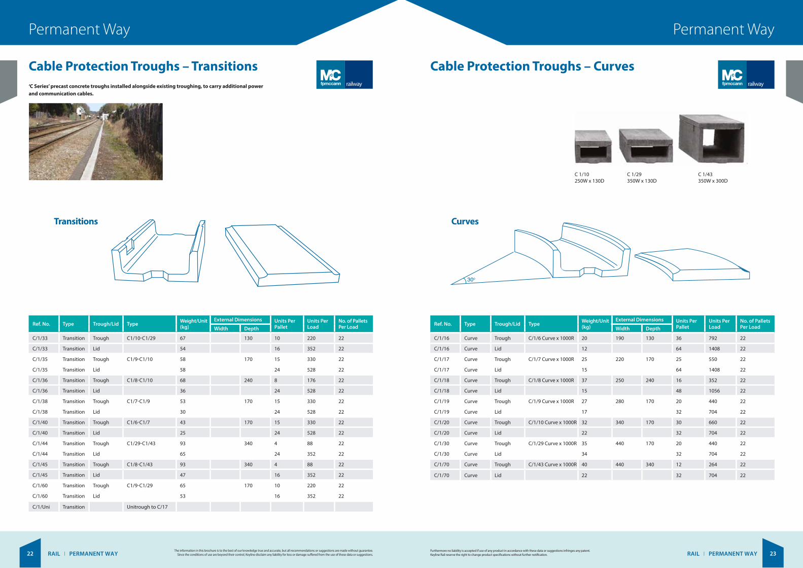
Cable Protection Troughs – Transitions Cable Protection Troughs – Curves ‘C Series’ precast concrete troughs installed alongside existing troughing, to carry additional power and communication cables.
The information in this brochure is to the best of our knowledge true and accurate, but all recommendations or suggestions are made without guarantee. Since the conditions of use are beyond their control, Keyline disclaim any liability for loss or damage suffered from the use of these data or suggestions.
Furthermore no liability is accepted if use of any product in accordance with these data or suggestions infringes any patent. Keyline Rail reserve the right to change product specifications without further notification.
Ref. No. Type Trough/Lid Type Weight/Unit (kg)
External Dimensions Units Per Pallet
Units Per Load
No. of Pallets Per LoadWidth Depth
C/1/33 Transition Trough C1/10-C1/29 67 130 10 220 22
C/1/33 Transition Lid 54 16 352 22
C/1/35 Transition Trough C1/9-C1/10 58 170 15 330 22
C/1/35 Transition Lid 58 24 528 22
C/1/36 Transition Trough C1/8-C1/10 68 240 8 176 22
C/1/36 Transition Lid 36 24 528 22
C/1/38 Transition Trough C1/7-C1/9 53 170 15 330 22
C/1/38 Transition Lid 30 24 528 22
C/1/40 Transition Trough C1/6-C1/7 43 170 15 330 22
C/1/40 Transition Lid 25 24 528 22
C/1/44 Transition Trough C1/29-C1/43 93 340 4 88 22
C/1/44 Transition Lid 65 24 352 22
C/1/45 Transition Trough C1/8-C1/43 93 340 4 88 22
C/1/45 Transition Lid 47 16 352 22
C/1/60 Transition Trough C1/9-C1/29 65 170 10 220 22
C/1/60 Transition Lid 53 16 352 22
C/1/Uni Transition Unitrough to C/17
C U R V E S
Ref. No. Type Trough/Lid Type Weight/UnitKg
Extenal DimensionsUnits per
palletUnits per
loadWidth Depth
C/1/16C/1/16
C/1/17C/1/17
2515
220 170 2564
5501408
CurveCurve
CurveCurve
TroughLid
TroughLid
2012
190 3664
7921408
130C/1/6 Curve x 1000R
C/1/7 Curve x 1000R
C/1/18C/1/18
3715
250 240 1648
3521056
CurveCurve
TroughLid
C/1/8 Curve x 1000R
C/1/19C/1/19
2717
280 170 2032
440704
CurveCurve
TroughLid
C/1/9 Curve x 1000R
C/1/20C/1/20
3222
340 170 3032
660704
CurveCurve
TroughLid
C/1/10 Curve x 1000R
C/1/30C/1/30
3534
440 170 2032
440704
CurveCurve
TroughLid
C/1/29 Curve x 1000R
C/1/70C/1/70
4022
440 340 1232
264704
CurveCurve
TroughLid
C/1/43 Curve x 1000R
No of palletsper load
2222
2222
2222
2222
2222
2222
2222
T E E S
Ref. No. Type Trough/Lid Type Weight/UnitKg
Units perpallet
Units perload
No of palletsper loadWidth Depth
C/1/23C/1/23
C/1/32C/1/32
8188
440/340 170 816
176352
2222
TeeTee
TeeTee
TroughLid
TroughLid
9954
250 816
176352
2222
240
C/1/34C/1/34
7360
340 170 1016
220352
2222
TeeTee
TroughLid
C/1/37C/1/37
6852
280 170 1016
220352
2222
TeeTee
TroughLid
C/1/9 off C/1/9
C/1/39C/1/39
7043
220 170 1016
220352
2222
TeeTee
TroughLid
C/1/7 off C/1/7
C/1/41C/1/41
5139
190 130 1216
264352
2222
TeeTee
TroughLid
C/1/6 off C/1/6
C/1/42C/1/42
7733
440/250 240/170 816
176352
2222
TeeTee
TroughLid
C/1/8 Branch off C/1/29
C/1/80C/1/80
7165
440 170 1016
220352
2222
TeeTee
TroughLid
C/1/29 off C/1/29
C/1/81C/1/81
14065
440 340 616
132352
2222
TeeTee
TroughLid
C/1/43 off C/1/43
C/1/8 off C/1/8
C/1/10 Branch off C/1/29
C/1/10 off C/1/10
Extenal Dimensions
C 1/43350W x 300D
C 1/29350W x 130D
C 1/10250W x 130D
Ref. No. Type Trough/Lid Type Weight/Unit (kg)
External Dimensions Units Per Pallet
Units Per Load
No. of Pallets Per LoadWidth Depth
C/1/16 Curve Trough C/1/6 Curve x 1000R 20 190 130 36 792 22
C/1/16 Curve Lid 12 64 1408 22
C/1/17 Curve Trough C/1/7 Curve x 1000R 25 220 170 25 550 22
C/1/17 Curve Lid 15 64 1408 22
C/1/18 Curve Trough C/1/8 Curve x 1000R 37 250 240 16 352 22
C/1/18 Curve Lid 15 48 1056 22
C/1/19 Curve Trough C/1/9 Curve x 1000R 27 280 170 20 440 22
C/1/19 Curve Lid 17 32 704 22
C/1/20 Curve Trough C/1/10 Curve x 1000R 32 340 170 30 660 22
C/1/20 Curve Lid 22 32 704 22
C/1/30 Curve Trough C/1/29 Curve x 1000R 35 440 170 20 440 22
C/1/30 Curve Lid 34 32 704 22
C/1/70 Curve Trough C/1/43 Curve x 1000R 40 440 340 12 264 22
C/1/70 Curve Lid 22 32 704 22
railwayrailway

NEWINNOVATION IN
CONCRETEJUST ADD WATER!
RAIL I PERMANENT WAY 25RAIL I PERMANENT WAY24
Permanent WayPermanent Way
Cable Protection Troughs – Tees Concrete CanvasTM
Trough-LiteTM Lightweight cable protection troughs
Concrete Canvas (CC) key facts:
Rapid Install CC can be laid at a rate of 200sqm/hour, up to 10 times faster than conventional concrete solutions
Easy to Use CC is available in man portable rolls for applications with limited access. The concrete is pre-mixed so there is no need for mixing, measuring or compacting. Just add water
Lower Project Costs The speed and ease of installation mean CC is more cost-effective than conventional concrete, with less logistical complexity
Eco-Friendly CC is a low mass, low carbon technology which uses up to 95% less material than conventional concrete for many applications
Water Proof The PVC backing on one surface of the Canvas ensures that the material has excellent impermeability
Strong The fibre reinforcement prevents cracking, absorbs energy from impacts and provides a stable failure mode
Durable CC is chemically resistant, has good weathering performance and will not degrade in UV
Flexible CC has good drape characteristics and will closely follow the profile of any ditch or embankment. The material can negotiate tight bends and fit around existing infrastructure. Unset CC can be cut or tailored using basic hand tools.
The information in this brochure is to the best of our knowledge true and accurate, but all recommendations or suggestions are made without guarantee. Since the conditions of use are beyond their control, Keyline disclaim any liability for loss or damage suffered from the use of these data or suggestions.
Furthermore no liability is accepted if use of any product in accordance with these data or suggestions infringes any patent. Keyline Rail reserve the right to change product specifications without further notification.
Using lightweight concrete technology, that has been utilised and proven for years when manufacturing concrete fencing products, FP McCann have developed a lightweight
C series troughing system. The lightweight Trough-Lite system has the same dimensions as the company’s traditional products, so that two systems are fully compatible. Trough-Lite reduces the concerns associated with manual handling due to a weight reduction of up to 30%, when compared to standard concrete.
Trough-Lite is a cost effective lightweight product that is up to 50% cheaper than alternative lightweight products currently available. This lightweight solution offers additional benefits including:
Faster installation
Lower on-site labour costs
Reduction in transportation costs
Reduced carbon footprint and increased sustainability, as the concrete mix uses over 50% recycled content.
Tees
C U R V E S
Ref. No. Type Trough/Lid Type Weight/UnitKg
Extenal DimensionsUnits per
palletUnits per
loadWidth Depth
C/1/16C/1/16
C/1/17C/1/17
2515
220 170 2564
5501408
CurveCurve
CurveCurve
TroughLid
TroughLid
2012
190 3664
7921408
130C/1/6 Curve x 1000R
C/1/7 Curve x 1000R
C/1/18C/1/18
3715
250 240 1648
3521056
CurveCurve
TroughLid
C/1/8 Curve x 1000R
C/1/19C/1/19
2717
280 170 2032
440704
CurveCurve
TroughLid
C/1/9 Curve x 1000R
C/1/20C/1/20
3222
340 170 3032
660704
CurveCurve
TroughLid
C/1/10 Curve x 1000R
C/1/30C/1/30
3534
440 170 2032
440704
CurveCurve
TroughLid
C/1/29 Curve x 1000R
C/1/70C/1/70
4022
440 340 1232
264704
CurveCurve
TroughLid
C/1/43 Curve x 1000R
No of palletsper load
2222
2222
2222
2222
2222
2222
2222
T E E S
Ref. No. Type Trough/Lid Type Weight/UnitKg
Units perpallet
Units perload
No of palletsper loadWidth Depth
C/1/23C/1/23
C/1/32C/1/32
8188
440/340 170 816
176352
2222
TeeTee
TeeTee
TroughLid
TroughLid
9954
250 816
176352
2222
240
C/1/34C/1/34
7360
340 170 1016
220352
2222
TeeTee
TroughLid
C/1/37C/1/37
6852
280 170 1016
220352
2222
TeeTee
TroughLid
C/1/9 off C/1/9
C/1/39C/1/39
7043
220 170 1016
220352
2222
TeeTee
TroughLid
C/1/7 off C/1/7
C/1/41C/1/41
5139
190 130 1216
264352
2222
TeeTee
TroughLid
C/1/6 off C/1/6
C/1/42C/1/42
7733
440/250 240/170 816
176352
2222
TeeTee
TroughLid
C/1/8 Branch off C/1/29
C/1/80C/1/80
7165
440 170 1016
220352
2222
TeeTee
TroughLid
C/1/29 off C/1/29
C/1/81C/1/81
14065
440 340 616
132352
2222
TeeTee
TroughLid
C/1/43 off C/1/43
C/1/8 off C/1/8
C/1/10 Branch off C/1/29
C/1/10 off C/1/10
Extenal Dimensions
Ref. No. Type Trough/Lid Type Weight/Unit (kg)
External Dimensions Units Per Pallet
Units Per Load
No. of Pallets Per LoadWidth Depth
C/1/23 Tee Trough C/1/8 off C/1/8 99 250 240 8 176 22
C/1/23 Tee Lid 54 16 352 22
C/1/32 Tee Trough C/1/10 Branch off C/1/29 81 440/340 170 8 176 22
C/1/32 Tee Lid 88 16 352 22
C/1/34 Tee Trough C/1/10 off C/1/10 73 340 170 10 220 22
C/1/34 Tee Lid 60 16 352 22
C/1/37 Tee Trough C/1/9 off C/1/9 68 280 170 10 220 22
C/1/37 Tee Lid 52 16 352 22
C/1/39 Tee Trough C/1/7 off C/1/7 70 220 170 10 220 22
C/1/39 Tee Lid 43 16 352 22
C/1/41 Tee Trough C/1/6 off C/1/6 51 190 130 12 264 22
C/1/41 Tee Lid 39 16 352 22
C/1/42 Tee Trough C/1/8 Branch off C/1/6 77 440/250 240/170 8 176 22
C/1/42 Tee Lid 33 16 352 22
C/1/80 Tee Trough C/1/29 off C/1/29 71 440 170 10 220 22
C/1/80 Tee Lid 65 16 352 22
C/1/81 Tee Trough C/1/43 off C/1/43 140 440 340 6 132 22
C/1/81 Tee Lid 65 16 352 22
Concrete Canvas (CC), is a flexible, concrete impregnated fabric that hardens when hydrated to form a thin, durable, waterproof concrete layer. CC allows concrete construction without the need for plant or mixing equipment. Simply position the Canvas and just add water. CC consists of a 3-dimensional fibre matrix containing a specially formulated dry concrete mix. A PVC backing on one surface of the canvas ensures the material is waterproof. The
material can be hydrated either by spraying or by being fully immersed in water. Once set, the fibres reinforce the concrete, preventing crack propagation and providing a safe plastic failure mode.
CC is available in 3 thicknesses: CC5, CC8 and CC13, which are 5, 8 and 13mm thick respectively.
Concrete Canvas applications
Ditch Lining Culverts Erosion Control Pipeline Protection
railway

RAIL I PERMANENT WAY 27RAIL I PERMANENT WAY26
Permanent WayPermanent Way
Concrete CanvasTM Concrete CanvasTM Material Data
Pre-Set CC Properties Setting Working Time: 1-2 hours subject to ambient temperature CC will achieve 80% strength at 24 hours after hydration.
Method of Hydration Spray the fibre surface with water until it feels wet to touch for several minutes after spraying.
Re-spray the CC again after 1 hour if:
Installing CC5
Installing CC on a steep or vertical surface
Installing in warm climates.
Notes:
CC cannot be over hydrated and an excess of water is always recommended
Minimum ratio of water: CC is 1:2 by weight
Do not jet high pressure water directly onto the CC as this may wash a channel in the material
CC can be hydrated using saline or non-saline water
CC will hydrate and set underwater
CC has a working time of 1-2 hours after hydration. Do not move CC once it has begun to set
Working time will be reduced in hot climates
CC will set hard in 24 hours but will continue to gain strength for years
If CC is not fully saturated, the set may be delayed and strength reduced. If the set is delayed, re-wet with a large excess of water.
The information in this brochure is to the best of our knowledge true and accurate, but all recommendations or suggestions are made without guarantee. Since the conditions of use are beyond their control, Keyline disclaim any liability for loss or damage suffered from the use of these data or suggestions.
Furthermore no liability is accepted if use of any product in accordance with these data or suggestions infringes any patent. Keyline Rail reserve the right to change product specifications without further notification.
Post set data is based on CC hydrated in accordance with the CC Hydration Guide.
Strength Very high early strength is a fundamental characteristic of CC. Typical strengths and physical characteristics are as follows:
Compressive tests based on ASTM C109 – 02 (initial crack) – 10 day compressive failure stress (MPa) 40
Bending tests based on BS EN 12467:2004 (initial crack) – 10 day bending failure stress (MPa) 3.4 – 10 day bending Youngs modulus (MPa) 180
Tensile data (Initial crack)
CC has achieved Euroclass B certification: BS EN 13501-1:2007+A1:2009 B-s1, d0
CC has achieved MSHA approval: 30 CFR, Part 7, Subchapter B, Section 7.24 Passed
Patent ProtectedPat Pend/Granted: AE (766/2011), AE (932/2006), ARIPO (AP/P/2011/005842), AU (2010209524), AU (2005254788), BR (PI1005309-3), CA (2655054), CA (2749991), CA (2570532), CL (01809-2011), CN(201080005835.6), CO (11-092824), EP (2027319), EP (2393970), EP (1766162), GB (2455008), HK (12100037.1), ID (W00 2011 028 25), IL (214350), IN (5429/DELNP/2011), IN (20/DELNP/2007), JP (2011-546952), KR (10-2011-7020005), MN (3644), MX (MX/a/2011/007802), MY (PI2011003536), NO (20070245), NZ (594823), OM (OM/P/2011/00162), PH (1-2011-501468), RU (2011134016), RU (2386767), SG (201105143-0), TH (1101001335), US (8287982), US (US-2010-0233417-A1), US (13/146836), US(7721749), US (13/708074), VN (1-2011-02023), ZA (2009/00222), ZA (2011/06289), ZA (2007/0471) and other patents pending.
* Occasionally there will be a Beam Fault (fabric imperfection under 100mm wide running across the width) in a Bulk Roll. This fault is unavoidable due to the manufacturing process and the fault will be clearly marked with a red tag, there will be a maximum of (1) one Beam Fault in any Bulk Roll. A joint may need to be made on site where there is a Beam Fault as the material at a fault will not reach the performance specified in this Data Sheet. The maximum un-useable material due to any Beam Fault will be 100mm. There are no beam faults in standard batched rolls.
The information contained herein is offered free of charge and is, to the best of our knowledge, accurate. However, since the circumstances and conditions in which such information and the products discussed therein can be used may vary and are beyond our control, we make no warranty, express or implied, of merchantability, fitness or otherwise, or against patent infringement, and we accept no liability, with respect to or arising from use of such information or any such product.
© Concrete Canvas Ltd 2013
** For containment applications it is recommended to use CC as a protective overlay in combination with an appropriate sealed membrane liner. CC is not recommended as the sole barrier layer where impermeability is critical.
* Indicative values
Other Abrasion Resistance (DIN 52108) – Similar to twice that of OPC Max 0.10 gm/cm2
Manning’s Valve (ASTM D6460)
CBR Puncture Resistance EN ISO 12236: 2007 (CC8 and CC13 only) – Min. Push-through force 2.69kN – Max. Deflection at peak 38mm
Standard Test Method for Impact Resistance of Pipeline Coatings ASTM G13 (CC13 only) Passed
Freeze-thaw testing (ASTM C1185) 200 Cycles
Freeze-thaw testing (BS EN 12467:2004 part 5.5.2) Passed
Soak-dry testing (BS EN 12467:2004 part 5.5.5) Passed
Water impermeability (BS EN 12467:2004 part 5.4.4) Passed**
Post Set CC Properties
Reaction to Fire
CC Patent Information
CC Physical Properties*
CC Thickness(mm)
Batch RollSize (m2)
Bulk RollSize (m2)
Roll Width(m)
CC5 5 10 200 1.0
CC8 8 5 125 1.1
CC13 13 N/A 80 1.1
CC Mass (unset)(kg/m2)
Density (unset)(kg/m3)
Density (set)(kg/m3)
CC5 7 1500 +30-35%
CC8 12 1500 +30-35%
CC13 19 1500 +30-35%
Tensile strength (kN/m)
Length direction Width direction
CC5 6.7 3.8
CC8 8.6 6.6
CC13 19.5 12.8
Concrete Canvas Ltd.CF37 5SP, United Kingdom
11EN12467:2004Concrete Canvas:Fibre cement sheetNTOversize sheetsClass 1, Category AReaction to Fire B-s1,d0
CC Type Thickness Batch Roll Size Bulk Roll Size Roll Width Mass Unset Density Unset Set
CC5 5mm 10m2 200m2 1m 7kg/m2 1500kg/m3 +30-35%
CC8 8mm 5m2 125m2 1.1m 12kg/m2 1500kg/m3 +30-35%
CC13 13mm n/a 80m2 1.1m 19kg/m2 1500kg/m3 +30-35%
SETTING Initial Set > 2 hours Final Set < 24 hours CC will achieve 80% strength at 24 hours after hydration.

RAIL I PERMANENT WAY28
Permanent Way
Ballast Mats
Sleeper Pads
Reduction of noise and vibrations in ballasted tracks
Installed in areas with reduced ballast depth to keep ballast in good condition
Reduction of maintainance costs
Weather independent installation possible.
Reduce stresses and wear on the ballast under the concrete sleeper
Improve track stability
Quick installation, unaffected by weather conditions
Reduce noise and vibrations.
The information in this brochure is to the best of our knowledge true and accurate, but all recommendations or suggestions are made without guarantee. Since the conditions of use are beyond their control, Keyline disclaim any liability for loss or damage suffered from the use of these data or suggestions.
Allow a high level of track elasticity to be achieved. Sylomer and Sylodyn ballast mats are installed for reduction of secondary airborne noise, vibrations. Also they are installed in areas with very low ballast depth.
Installed in high-speed rail lines and in lines with high axle loads, as well as in standard lines. No additional work at installation site required, as they can be installed on the sleepers during their production in the factory.
Travis Perkins operates some of the leading brands in the industry, 20 businesses from more than 1,800 sites across the UK.
Benchmarx - Benchmarx Kitchens & Joinery is a strictly trade only company supplying high quality kitchens, joinery and flooring and everything else to complete the job.
Birchwood Price Tools - Birchwood Price Tools (BPT) is a leading wholesaler of power tools, hand tools and site equipment, carrying a distinguished line-up of global brands.
City Plumbing Supplies - One of the UK’s largest plumbers’ merchants and bathroom retailers, with a dedicated national network of branches and bathroom showrooms.
CCF - leading specialist distributors of ceilings, drywall, screeding, insulation, partitioning and fire protection to the construction industry.
City Heating Spares - City Heating Spares is the new super-fast heating spares brand trading at selected City Plumbing Supplies branches.
Direct Heating Spares - Direct Heating Spares Limited (‘DHS’) is a leading independent distributor of domestic heating spares in the UK with national coverage.
F & P Wholesale - The independent merchants’ choice for heating, plumbing and bathroom products.
BSS Industrial - Pipeline & Heating Solutions – A specialist distributor of pipeline, heating and mechanical services equipment serving customers across all industrial sectors within the UK and Ireland.
Plumbing Trade Supplies - PTS is a leading distributor of plumbing, heating, sanitaryware and renewable energy products to a wide range of customers, both public and private sector, from national house builders to the sole trading plumber.
Travis Perkins - One of the UK’s leading builders’ merchants supplying more than 100,000 product lines to trade professionals and self-builders.
Tile Giant - Tile Giant is the fastest growing ceramics merchant in the UK.
Toolstation - Toolstation is a rapidly growing direct retailer of tools and hardware.
Wickes - One of the UK’s leading DIY and Home Improvement retailers, operating over 200 stores across the country.
Connections - A leading distributor of plumbing fittings from leading brands and manufacturers.
Solfex - One of the largest specialist distributors in the UK of high quality renewable energy systems.