Embed Size (px)
Citation preview
Diagnostic Manual, TSD 3453E, Issue 1 i
Perkins 2300 SeriesModel 2306C-E14
DIAGNOSTIC MANUAL
6 cylinder turbocharged diesel engine
Publication TSD 3457E, Issue 1.© Proprietary information of Perkins Engines Company Limited, all rights reserved.The information is correct at the time of print.Published in August 2002 by Technical Publications,Perkins Engines Company Limited, Tixall Road, Stafford, ST16 3UB, England
ii Diagnostic Manual, TSD 3453E, Issue 1
Chapters
1 General information
2 Electronic system overview
3 Programming parameters
4 Fault diagnosis
5 Special Tools
The following pages contain a detailed table of contents
Diagnostic Manual, TSD 3457E, Issue 1 iii
2300 Series
Contents
1 General informationIntroduction ... ... ... ... ... ... ... ... ... ... ... ... ... ... ... ... ... ... ... ... ... ... ... ... ... ... ... ... ... ... 1
Safety precautions ... ... ... ... ... ... ... ... ... ... ... ... ... ... ... ... ... ... ... ... ... ... ... ... ... ... ... 2
Glossary of terms . ... ... ... ... ... ... ... ... ... ... ... ... ... ... ... ... ... ... ... ... ... ... ... ... ... ... ... 3
2 Electronic system overviewSystem operation .. ... ... ... ... ... ... ... ... ... ... ... ... ... ... ... ... ... ... ... ... ... ... ... ... ... ... ... 9
Electronic controls ... ... ... ... ... ... ... ... ... ... ... ... ... ... ... ... ... ... ... ... ... ... ... ... ... ... ... 9
Engine governor ... ... ... ... ... ... ... ... ... ... ... ... ... ... ... ... ... ... ... ... ... ... ... ... ... ... ... ... 9
Timing considerations .. ... ... ... ... ... ... ... ... ... ... ... ... ... ... ... ... ... ... ... ... ... ... ... ... ... 9
Fuel injection . ... ... ... ... ... ... ... ... ... ... ... ... ... ... ... ... ... ... ... ... ... ... ... ... ... ... ... ... . 10
Engine monitoring ... ... ... ... ... ... ... ... ... ... ... ... ... ... ... ... ... ... ... ... ... ... ... ... ... ... . 11
Fuel temperature monitoring ... ... ... ... ... ... ... ... ... ... ... ... ... ... ... ... ... ... ... ... ... ... . 11
Self diagnostics ... ... ... ... ... ... ... ... ... ... ... ... ... ... ... ... ... ... ... ... ... ... ... ... ... ... ... . 11
Effect of diagnostic codes on engine performance .. ... ... ... ... ... ... ... ... ... ... ... ... . 12
Current totals stored in the ECM . ... ... ... ... ... ... ... ... ... ... ... ... ... ... ... ... ... ... ... ... . 12
Programmable parameters .. ... ... ... ... ... ... ... ... ... ... ... ... ... ... ... ... ... ... ... ... ... ... . 12
Passwords . ... ... ... ... ... ... ... ... ... ... ... ... ... ... ... ... ... ... ... ... ... ... ... ... ... ... ... ... ... . 13
iv Diagnostic Manual, TSD 3457E, Issue 1
2300 Series
Engine component diagram . ... ... ... ... ... ... ... ... ... ... ... ... ... ... ... ... ... ... ... ... ... ... 14
OEM connection diagram . ... ... ... ... ... ... ... ... ... ... ... ... ... ... ... ... ... ... ... ... ... ... ... 15
Sensor and connector location diagram . ... ... ... ... ... ... ... ... ... ... ... ... ... ... ... ... ... 16
Engine wiring diagram .. ... ... ... ... ... ... ... ... ... ... ... ... ... ... ... ... ... ... ... ... ... ... ... ... 17
Machine wiring diagram (all options) .. ... ... ... ... ... ... ... ... ... ... ... ... ... ... ... ... ... ... 18
Electrical connectors and functions ... ... ... ... ... ... ... ... ... ... ... ... ... ... ... ... ... ... ... 19
Colour codes .. ... ... ... ... ... ... ... ... ... ... ... ... ... ... ... ... ... ... ... ... ... ... ... ... ... ... ... ... 19
Service tools and diagnostics .. ... ... ... ... ... ... ... ... ... ... ... ... ... ... ... ... ... ... ... ... ... 20
3 Programming parametersConnecting the TIPSS-EST ... ... ... ... ... ... ... ... ... ... ... ... ... ... ... ... ... ... ... ... ... ... ... 21
Passwords .. ... ... ... ... ... ... ... ... ... ... ... ... ... ... ... ... ... ... ... ... ... ... ... ... ... ... ... ... ... 23
Programming a new ECM . ... ... ... ... ... ... ... ... ... ... ... ... ... ... ... ... ... ... ... ... ... ... ... 24
Programming an ECM using flash programming ... ... ... ... ... ... ... ... ... ... ... ... ... ... 27
ECM date/time clock .. ... ... ... ... ... ... ... ... ... ... ... ... ... ... ... ... ... ... ... ... ... ... ... ... ... 28
ECM diagnostic clock ... ... ... ... ... ... ... ... ... ... ... ... ... ... ... ... ... ... ... ... ... ... ... ... ... 29
Injector codes ... ... ... ... ... ... ... ... ... ... ... ... ... ... ... ... ... ... ... ... ... ... ... ... ... ... ... ... 29
TIPSS-EST cylinder cut-out test ... ... ... ... ... ... ... ... ... ... ... ... ... ... ... ... ... ... ... ... ... 29
Programming parameters . ... ... ... ... ... ... ... ... ... ... ... ... ... ... ... ... ... ... ... ... ... ... ... 29
System configuration parameters ... ... ... ... ... ... ... ... ... ... ... ... ... ... ... ... ... ... ... ... 30
Customer specified parameters ... ... ... ... ... ... ... ... ... ... ... ... ... ... ... ... ... ... ... ... ... 32
4 Fault diagnosis
Introduction ... ... ... ... ... ... ... ... ... ... ... ... ... ... ... ... ... ... ... ... ... ... ... ... ... ... ... ... ... 35
Diagnostic procedures without a diagnostic fault code
General information .. ... ... ... ... ... ... ... ... ... ... ... ... ... ... ... ... ... ... ... ... ... ... ... ... ... 36
Diagnostic symptoms
Test 1 - Engine will not crank . ... ... ... ... ... ... ... ... ... ... ... ... ... ... ... ... ... ... ... ... ... ... 37
Diagnostic Manual, TSD 3457E, Issue 1 v
2300 Series
Test 2 - Engine cranks but will not start ... ... ... ... ... ... ... ... ... ... ... ... ... ... ... ... ... ... . 38Test 3 - Engine misfires, runs rough or is unstable ... ... ... ... ... ... ... ... ... ... ... ... ... ... . 39Test 4 - Low power/poor or no response to throttle ... ... ... ... ... ... ... ... ... ... ... ... ... ... . 40Test 5 - Intermittent engine shutdowns . ... ... ... ... ... ... ... ... ... ... ... ... ... ... ... ... ... ... . 41Test 6 - Intermittent low power or power cut-outs . ... ... ... ... ... ... ... ... ... ... ... ... ... ... . 42Test 7 - Electronic service tool will not communicate with the ECM . ... ... ... ... ... ... ... . 43Test 8 - ECM will not accept factory passwords ... ... ... ... ... ... ... ... ... ... ... ... ... ... ... . 44Test 9 - Excessive black smoke ... ... ... ... ... ... ... ... ... ... ... ... ... ... ... ... ... ... ... ... ... . 45Test 10 - Excessive white smoke .. ... ... ... ... ... ... ... ... ... ... ... ... ... ... ... ... ... ... ... ... . 46Test 11 - Excessive blue smoke ... ... ... ... ... ... ... ... ... ... ... ... ... ... ... ... ... ... ... ... ... . 47Test 12 - Engine cannot reach correct rev/min . ... ... ... ... ... ... ... ... ... ... ... ... ... ... ... . 48Test 13 - Poor acceleration or response ... ... ... ... ... ... ... ... ... ... ... ... ... ... ... ... ... ... . 49Test 14 - Poor fuel consumption ... ... ... ... ... ... ... ... ... ... ... ... ... ... ... ... ... ... ... ... ... . 50Test 15 - Too much vibration . ... ... ... ... ... ... ... ... ... ... ... ... ... ... ... ... ... ... ... ... ... ... . 51Test 16 - Noise coming from cylinder ... ... ... ... ... ... ... ... ... ... ... ... ... ... ... ... ... ... ... . 52Test 17 - Excessive valve clearance . ... ... ... ... ... ... ... ... ... ... ... ... ... ... ... ... ... ... ... . 53Test 18 - Valve rotocoil or spring lock is free ... ... ... ... ... ... ... ... ... ... ... ... ... ... ... ... . 54Test 19 - Mechanical noise (knock) in engine ... ... ... ... ... ... ... ... ... ... ... ... ... ... ... ... . 55Test 20 - Oil in cooling system .. ... ... ... ... ... ... ... ... ... ... ... ... ... ... ... ... ... ... ... ... ... . 56Test 21 - Fuel in cooling system ... ... ... ... ... ... ... ... ... ... ... ... ... ... ... ... ... ... ... ... ... . 57Test 22 - Coolant in lubricating oil . ... ... ... ... ... ... ... ... ... ... ... ... ... ... ... ... ... ... ... ... . 58Test 23 - Fuel dilution of lubricating oil .. ... ... ... ... ... ... ... ... ... ... ... ... ... ... ... ... ... ... . 59Test 24 - Engine has early wear ... ... ... ... ... ... ... ... ... ... ... ... ... ... ... ... ... ... ... ... ... . 60Test 25 - Engine has low oil pressure ... ... ... ... ... ... ... ... ... ... ... ... ... ... ... ... ... ... ... . 61Test 26 - Engine uses too much lubricating oil .. ... ... ... ... ... ... ... ... ... ... ... ... ... ... ... . 62Test 27 - Engine coolant is too hot ... ... ... ... ... ... ... ... ... ... ... ... ... ... ... ... ... ... ... ... . 63Test 28 - Oil at the exhaust ... ... ... ... ... ... ... ... ... ... ... ... ... ... ... ... ... ... ... ... ... ... ... . 64Test 29 - Engine has a fuel supply problem .. ... ... ... ... ... ... ... ... ... ... ... ... ... ... ... ... . 65Test 30 - Indicator lamp not functioning correctly .. ... ... ... ... ... ... ... ... ... ... ... ... ... ... . 66Test 31 - Inlet air manifold temperature is too high ... ... ... ... ... ... ... ... ... ... ... ... ... ... . 67Test 32 - Engine has a high fuel temperature ... ... ... ... ... ... ... ... ... ... ... ... ... ... ... ... . 68
Diagnostic procedures with an event code
General information .. ... ... ... ... ... ... ... ... ... ... ... ... ... ... ... ... ... ... ... ... ... ... ... ... ... . 69
Event codes ... ... ... ... ... ... ... ... ... ... ... ... ... ... ... ... ... ... ... ... ... ... ... ... ... ... ... ... ... . 69
Diagnostic tests
Test 33 - High intake manifold pressure ... ... ... ... ... ... ... ... ... ... ... ... ... ... ... ... ... ... . 70Test 34 - Low oil pressure . ... ... ... ... ... ... ... ... ... ... ... ... ... ... ... ... ... ... ... ... ... ... ... . 71Test 35 - High coolant temperature ... ... ... ... ... ... ... ... ... ... ... ... ... ... ... ... ... ... ... ... . 72Test 36 - Engine overspeed .. ... ... ... ... ... ... ... ... ... ... ... ... ... ... ... ... ... ... ... ... ... ... . 73Test 37 - High fuel temperature . ... ... ... ... ... ... ... ... ... ... ... ... ... ... ... ... ... ... ... ... ... . 74Test 38 - High intake manifold air temperature . ... ... ... ... ... ... ... ... ... ... ... ... ... ... ... . 75
Diagnostic procedures with a diagnostic fault code
General information .. ... ... ... ... ... ... ... ... ... ... ... ... ... ... ... ... ... ... ... ... ... ... ... ... ... . 76
Diagnostic codes .. ... ... ... ... ... ... ... ... ... ... ... ... ... ... ... ... ... ... ... ... ... ... ... ... ... ... . 76
vi Diagnostic Manual, TSD 3457E, Issue 1
2300 Series
Diagnostic terminology . ... ... ... ... ... ... ... ... ... ... ... ... ... ... ... ... ... ... ... ... ... ... ... ... 78
Connectors . ... ... ... ... ... ... ... ... ... ... ... ... ... ... ... ... ... ... ... ... ... ... ... ... ... ... ... ... ... 79
Diagnostic tests
Test 39 - Inspecting electrical connectors .. ... ... ... ... ... ... ... ... ... ... ... ... ... ... ... ... ... 82Test 40 - Electrical power supply to the ECM ... ... ... ... ... ... ... ... ... ... ... ... ... ... ... ... 88Test 41 - Analogue sensor open or short circuit test . ... ... ... ... ... ... ... ... ... ... ... ... ... 91Test 42 - ECM Status indicator output circuit test .. ... ... ... ... ... ... ... ... ... ... ... ... ... .. 101Test 43 - +5 V Sensor voltage supply circuit test ... ... ... ... ... ... ... ... ... ... ... ... ... ... .. 107Test 44 - PWM desired speed setting circuit test ... ... ... ... ... ... ... ... ... ... ... ... ... ... .. 112Test 45 - Perkins Data Link circuit test .. ... ... ... ... ... ... ... ... ... ... ... ... ... ... ... ... ... .. 118Test 46 - Engine speed/timing circuit test .. ... ... ... ... ... ... ... ... ... ... ... ... ... ... ... ... .. 126Test 47 - Engine speed/timing calibration .. ... ... ... ... ... ... ... ... ... ... ... ... ... ... ... ... .. 134Test 48 - Injector solenoids circuit test ... ... ... ... ... ... ... ... ... ... ... ... ... ... ... ... ... ... .. 138Test 49 - Analogue sensor abnormal test .. ... ... ... ... ... ... ... ... ... ... ... ... ... ... ... ... .. 146
5 Special toolsRequired service tools .. ... ... ... ... ... ... ... ... ... ... ... ... ... ... ... ... ... ... ... ... ... ... ... .. 149
Optional service tools ... ... ... ... ... ... ... ... ... ... ... ... ... ... ... ... ... ... ... ... ... ... ... ... .. 150
Diagnostic Manual, TSD 3457E, Issue 1 1
12300 Series
General information 1
Introduction
The 2300 and 2800 Series industrial diesel engines are the latest development from Perkins Engines Company Limited, a world leader in the design and manufacture of high performance diesel engines.
Read and remember the "Safety precautions" on page 2. They are given for your protection and must be applied at all times.
Danger is indicated in the text by two methods:
Warning! This indicates that there is a possible danger to the person.
Caution: This indicates that there is a possible danger to the engine.
Note: Is used where the information is important, but there is not a danger.
Ensure that all adjustments and repairs are done by personnel who have had the correct training.
1
2 Diagnostic Manual, TSD 3457E, Issue 1
2300 Series
Safety precautions
These safety precautions are important. Reference must also be made to the local regulations in the country of operation.
� Only use these engines in the type of application for which they have been designed.
� Do not change the specification of the engine.
� Do not smoke when you put fuel in the tank.
� Clean away fuel which has been spilt. Material which has been contaminated by fuel must be moved to a safe place.
� Do not put fuel in the tank while the engine runs (unless it is absolutely necessary).
� Do not clean, add lubricating oil, or adjust the engine while it runs (unless you have had the correct training; even then extreme caution must be used to prevent injury).
� Do not make adjustments that you do not understand.
� Ensure that the engine does not run in a location where it can cause a concentration of toxic emissions.
� Other persons must be kept at a safe distance while the engine or equipment is in operation.
� Do not permit loose clothing or long hair near moving parts.
� Keep away from moving parts during engine operation.
Warning! Some moving parts cannot be seen clearly while the engine runs.
� Do not operate the engine if a safety guard has been removed.
� Do not remove the filler cap of the cooling system while the engine is hot and while the coolant is under pressure, because dangerous hot coolant can be discharged.
� Do not use salt water or any other coolant which can cause corrosion in the closed coolant circuit.
� Do not allow sparks or fire near the batteries (especially when the batteries are on charge) because the gases from the electrolyte are highly flammable. The battery fluid is dangerous to the skin and especially to the eyes.
� Disconnect the battery terminals before a repair is made to the electrical system. Always disconnect the negative terminal first.
� Only one person must control the engine.
� Ensure that the engine is operated only from the control panel or from the operator’s position.
� If your skin comes into contact with high-pressure fuel, obtain medical assistance immediately.
� Diesel fuel and lubricating oil (especially used lubricating oil) can damage the skin of certain persons. Protect your hands with gloves or a special solution to protect the skin.
� Do not wear clothing which is contaminated by lubricating oil. Do not put material which is contaminated with oil into the pockets.
� Discard used lubricating oil in a safe place to prevent contamination.
� The combustible material of some components of the engine (for example certain seals) can become extremely dangerous if it is burned. Never allow this burnt material to come into contact with the skin or with the eyes.
� Fuel and oil pipes MUST be inspected for cracks or damage before they are fitted to the engine.
� Fit only genuine Perkins parts.
1
Diagnostic Manual, TSD 3457E, Issue 1 3
2300 Series
Glossary of terms
Active diagnostic code
Describes a condition that is currently present to alert the operator or service technician of an abnormal engine operation parameter. See also Diagnostic fault code.
Aftermarket device
A device or an accessory that is installed by the customer or OEM after the engine has been delivered.
Alternating current (AC)
The direction of current flow changes (alternates) regularly and constantly in a circuit.
Atmospheric pressure sensor
Analogue sensor generates a signal proportional to atmospheric (barometric) air pressure in the crankcase and sends a signal to the ECM.
Before top center (BTC)
The 180° of crankshaft rotation before the piston reaches the very top of its travel (normal direction of rotation).
Intake manifold pressure sensor
This sensor measures inlet manifold air pressure (boost pressure) and sends a signal to the ECM.
Bypass circuit
A circuit, usually temporary, to substitute for an existing circuit, typically for test purposes.
Calibration
An electronic adjustment of a sensor signal.
Perkins engine monitoring
The part of the Perkins Electronic Engine Control that monitors coolant temperature, oil pressure, intake manifold air temperature and coolant level to alert the operator of detected problems. The coolant temperature, intake manifold air temperature, and oil pressure sensors are supplied by Perkins and monitored by the ECM. Aftermarket engine monitoring systems do not interface with the Perkins Electronic Engine Control.
Check engine lamp
Sometimes referred to as the diagnostic lamp, it is used to alert the operator of the presence of an active event.
Code
Refer to diagnostic fault code and diagnostic event code.
Cold mode
A mode of engine operation where the timing is retarded for engine protection, reduced smoke emissions and faster warm up time.
1
4 Diagnostic Manual, TSD 3457E, Issue 1
2300 Series
Component identifier (CID)
The CID is a number that identifies the specific component of the electronic control system that has experienced a diagnostic code. This is part of the PDL (Perkins Data Link).
Communication adapter
The communication adapter provides a communication link between the ECM and an electronic service tool.
Coolant temperature sensor
This sensor detects the engine coolant temperature for Cold Mode operation and Perkins Engine Monitoring.
Crankshaft position sensor
A sensor that measures the crankshaft position, the direction of rotation, and engine rev/min and sends signals to the ECM.
Customer specified parameter
A parameter value that can be changed and whose value is set by the customer. These parameters can be protected by customer passwords.
Desired rev/min
An input to the electronic governor in the ECM. The electronic governor uses inputs from the crankshaft position sensor and customer parameters to determine ’desired rev/min’.
Diagnostic event code
These codes indicate an event that describes an abnormal engine condition such as a shutdown occurrence. These codes are not necessarily (or usually) an indication of problems within the electronic system.
Diagnostic fault code
Sometimes referred to as a "fault code". These codes indicate an electronic system malfunction or problem with the engine electronic system.
Diagnostic lamp
Sometimes referred to as the "engine check lamp", it is used to alert the operator of the presence of an active diagnostic code.
Direct current (DC)
The type of current where the direction of current flow is consistently in one direction.
Duty cycle
Refer to pulse width modulation.
Engine control module (ECM)
The engine control computer that provides power to the engine electronics. It accepts inputs that monitor and outputs that control or change to act as a governor to control engine rev/min.
Electronically controlled unit injector
The injection pump which is a mechanically actuated, electronically controlled unit injector, combining the pumping, electronic fuel metering and injecting elements in a single unit.
Electronic engine control
The complete electronic system that monitors and controls the engine operation under all conditions.
Engine speed/timing sensor
Provides a variable amplitude and pulse width modulated signal to the ECM, which the ECM interprets as crankshaft position and engine speed.
Estimated dynamic timing
The ECM’s estimation of actual injection timing.
1
Diagnostic Manual, TSD 3457E, Issue 1 5
2300 Series
Failure mode identifier (FMI)
Type of failure that has been experienced by the component (adopted from the SAE standard practice of J1587 diagnostics).
Flash programming
A method of programming or updating an ECM with an electronic service tool over the data link instead of replacing components.
Fuel position
An internal signal within the ECM, from the electronic governor to the fuel injection control. It is based on desired rev/min, FRC fuel limit, rated fuel limit, and the actual engine rev/min.
Fuel ratio control (FRC)
A limit based on control of the fuel to air ratio and used for emission control purposes. When the ECM senses a higher intake manifold pressure (more air into cylinder), it increases the FRC fuel limit (allows more fuel into cylinder).
Fuel temperature sensor
This sensor detects the fuel temperature. The ECM monitors the fuel temperature and adjusts the calculated fuel rate accordingly.
Full load setting (FLS)
Number representing fuel system adjustment made at the factory to "fine tune" the fuel system maximum fuel delivery. Correct value for this parameter is stamped on the engine information ratings plate. This parameter must be programmed or a 268-02 Check Programmable Parameters diagnostic code will be generated.
Full torque setting (FTS)
Similar to the Full Load Setting. This parameter must be programmed or a 268-02 Check Programmable Parameters diagnostic code will be generated.
Harness
The wiring loom that connects all components of the electronic system.
Hertz (Hz)
Measure of electrical frequency in cycles per second.
1
6 Diagnostic Manual, TSD 3457E, Issue 1
2300 Series
Histogram
A bar graph indicating the relative frequency of engine operation in specific operating ranges.
Injector codes
Four digit code etched on the tappet or stamped on individual injectors of the electronic unit injectors.
Intake manifold air temperature sensor
This sensor detects the intake manifold air temperature. The ECM monitors the inlet air temperature and coolant temperature to adjust injection timing.
Integrated electronic controls
The engine is designed with the electronic controls as a necessary part of the system. The engine will not operate without the electronic controls.
J1939 data link
An SAE (Society of Automotive Engineers) standard data link used to communicate between the electronic engine, the transmission, and/or powertrain controls.
Logged diagnostic codes
Describes codes which are stored in memory. These codes are meant to be an indicator of possible causes for intermittent problems. Refer to diagnostic fault code.
Oil pressure sensor
This sensor measures engine oil pressure and sends a signal to the ECM as part of Perkins Engine Monitoring.
Open circuit
Condition where an electrical wire or connection is broken or a switch is open, so that the signal or the supply voltage can no longer reach its intended destination.
Original equipment manufacturer (OEM)
The manufacturer of equipment in which a Perkins engine is installed.
Parameter
A programmable value or limit which determines the characteristics or behaviour of the engine.
Parameter identifier (PID)
Two or three digit code which is assigned to each component in order to identify data via the data link to the ECM.
Password
A group of numeric or alphanumeric characters that is designed to restrict access to parameters. The electronic system requires correct passwords in order to change customer specified parameters (customer passwords) or certain engine specifications (factory passwords). Passwords are also required to clear certain diagnostic codes.
1
Diagnostic Manual, TSD 3457E, Issue 1 7
2300 Series
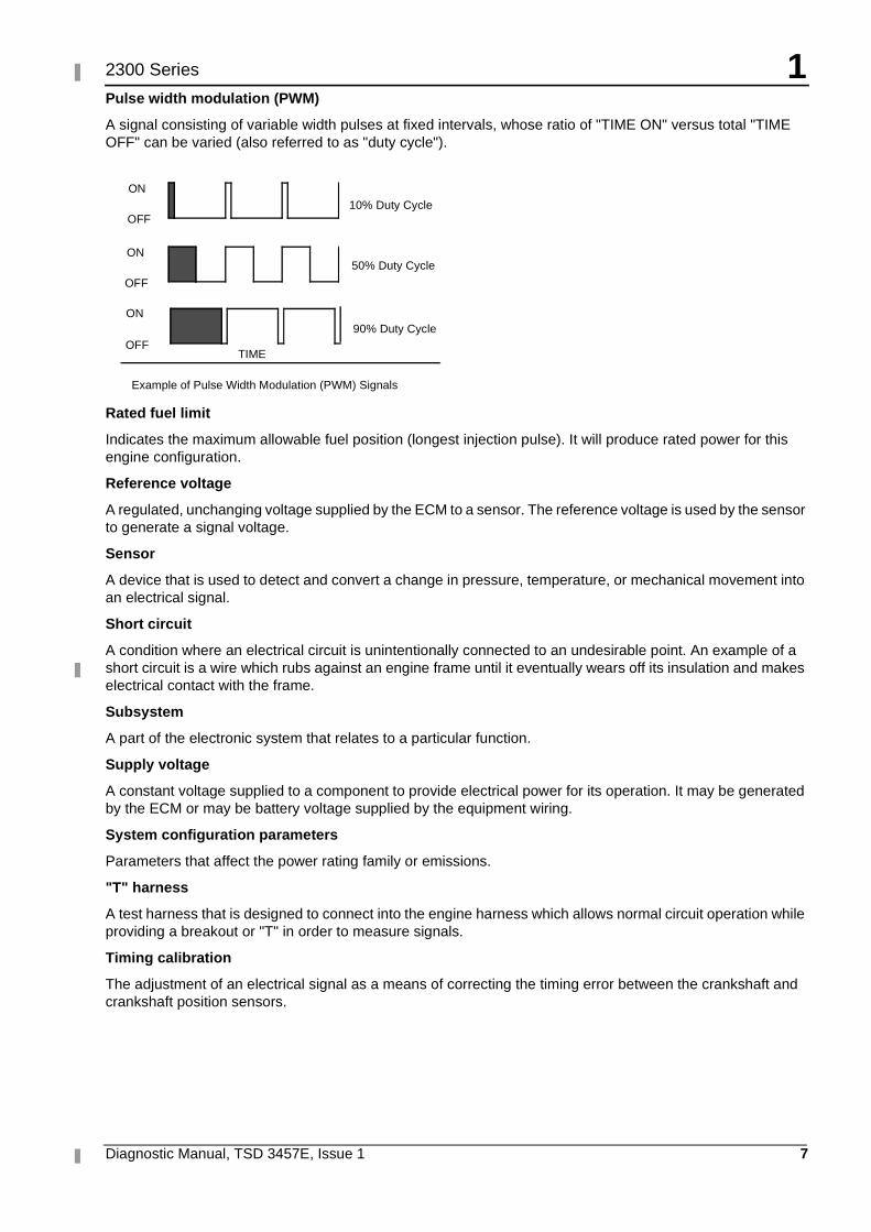
Pulse width modulation (PWM)
A signal consisting of variable width pulses at fixed intervals, whose ratio of "TIME ON" versus total "TIME OFF" can be varied (also referred to as "duty cycle").
Rated fuel limit
Indicates the maximum allowable fuel position (longest injection pulse). It will produce rated power for this engine configuration.
Reference voltage
A regulated, unchanging voltage supplied by the ECM to a sensor. The reference voltage is used by the sensor to generate a signal voltage.
Sensor
A device that is used to detect and convert a change in pressure, temperature, or mechanical movement into an electrical signal.
Short circuit
A condition where an electrical circuit is unintentionally connected to an undesirable point. An example of a short circuit is a wire which rubs against an engine frame until it eventually wears off its insulation and makes electrical contact with the frame.
Subsystem
A part of the electronic system that relates to a particular function.
Supply voltage
A constant voltage supplied to a component to provide electrical power for its operation. It may be generated by the ECM or may be battery voltage supplied by the equipment wiring.
System configuration parameters
Parameters that affect the power rating family or emissions.
"T" harness
A test harness that is designed to connect into the engine harness which allows normal circuit operation while providing a breakout or "T" in order to measure signals.
Timing calibration
The adjustment of an electrical signal as a means of correcting the timing error between the crankshaft and crankshaft position sensors.
ON
OFF10% Duty Cycle
ON
OFF
50% Duty Cycle
ON
OFF90% Duty Cycle
TIME
Example of Pulse Width Modulation (PWM) Signals

1
8 Diagnostic Manual, TSD 3457E, Issue 1
2300 Series
TIPSS-EST
A service tool software program to run on a personal computer (PC).
Total tattletale
Total number of changes to all the customer specified parameters stored in the ECM.
Diagnostic Manual, TSD 3457E, Issue 1 9
22300 Series
Electronic system overview 2
System operation
The 2300 and 2800 Series industrial diesel engines are designed for electronic control. The injection pump, fuel lines and nozzles used in mechanical engines have been replaced with an electronic unit injector in each cylinder. A solenoid on each injector controls the amount of fuel that is delivered by the injector. An Engine Control Module (ECM) sends a signal to each injector solenoid in order to provide complete control of the engine.
Electronic controls
The electronic system consists of the Engine Control Module (ECM), the engine sensors and the OEM interface. The ECM is the computer which controls the engine and contains the software which controls how the ECM behaves and stores the operating maps that define power, rev/min, etc.
Engine governor
The electronic controls on the engine serve as the engine governor, determining when and how much fuel to deliver to the cylinders based on the actual and desired conditions at any given time.
The ECM uses one of three possible speed control inputs to determine the desired engine speed and compares this to the actual engine speed determined through the crankshaft position sensor. If the desired engine speed is greater than the actual engine speed, more fuel is injected in order to increase engine speed.
Timing considerations
Once the ECM has determined how much fuel is required, it must next determine when to inject the fuel. Injection timing is determined by the ECM after considering input from the following components:
� Coolant temperature sensor
� Intake manifold air temperature sensor
� Atmospheric pressure sensor
� Intake manifold pressure sensor
The ECM determines where top centre on cylinder number one is located from the engine camshaft position sensor signal. The ECM decides when injection should occur relative to top centre and provides the signal to the injector at the desired time. The ECM adjusts timing for the best engine performance, fuel economy and white smoke control.
Note: Actual or desired timing cannot be viewed with the TIPSS-EST service tool.
2
10 Diagnostic Manual, TSD 3457E, Issue 1
2300 Series
Fuel injection
The ECM controls the amount of fuel injected by varying the signals to the injectors. The injectors will pump fuel only if the injector solenoid is energized. The ECM sends a high voltage signal to energize the solenoid. By controlling the timing and duration of the high voltage signal the ECM can control injection timing and the amount of fuel that is injected.
The software inside the ECM sets certain limits on the amount of fuel that can be injected. The fuel limit is a limit based on boost pressure to control the air/fuel ratio for control of emissions. When the ECM senses a higher boost pressure (more air into cylinder) it increases the fuel limit (allows more fuel into cylinder).
The Rated Fuel Limit is a limit that is based on the power rating of the engine and engine rev/min. It is similar to the rack stops and torque spring on a mechanically governed engine. It provides power and torque curves for a specific engine family and rating.
Note: All of these limits are determined at the factory in the ECM software and cannot be changed.
2
Diagnostic Manual, TSD 3457E, Issue 1 11
2300 Series
Engine monitoring
Perkins provides a factory installed engine monitoring system. The Perkins engine monitoring system monitors the following parameters:
� Engine oil pressure
� Coolant temperature
� Intake manifold air temperature
� Engine speed
� Boost pressure
� Fuel temperature
The Perkins engine monitoring system has three levels of operation, WARNING, ACTION ALERT and SHUTDOWN as described below.
Perkins engine monitoring WARNING operation
In the WARNING condition the ECM causes the Warning lamp to turn ON to indicate a problem has been detected by the Engine Monitoring System. No further ECM or engine action occurs.
Perkins engine monitoring ACTION ALERT operation
In the ACTION ALERT condition the ECM begins by activating the Action Alert lamp ON to indicate a problem has been detected by the Engine Monitoring System. This is also normally wired to cause a shutdown via the OEM control panel.
Perkins engine monitoring SHUTDOWN operation
If the fault reaches the SHUTDOWN condition the ECM activates the shutdown lamp and unless the engine is in CRITICAL OVERRIDE condition, the engine will shutdown.
Fuel temperature monitoring
The fuel temperature sensor monitors the fuel temperature, adjusting the ECM calculated fuel rate to compensate for fuel temperature changes and to adjust the fuel rate for constant power. The sensor is also used to warn the operator of excessive fuel temperature with a diagnostic event code because excessive fuel temperatures can adversely affect engine performance.
Self diagnostics
The electronic system has the ability to diagnose problems. When a problem is detected, a diagnostic code is generated and stored in permanent memory (logged) in the ECM. The diagnostic lamp is also activated.
When diagnostic codes occur, the diagnostic codes are referred to as Active diagnostic codes. They indicate that a problem of some kind currently exists.
Diagnostic codes that are stored in memory are called Logged diagnostic codes. Since the problem may have been temporary, or may have been repaired since the problem was logged, logged codes do not necessarily mean that something needs to be repaired. They are instead meant to be an indication of probable causes for intermittent problems.
Diagnostic codes that identify operating conditions outside the normal operating range are called Events. Event codes are not typically an indication of an electronic system problem.
Note: Some of the diagnostic codes require passwords to clear.
2
12 Diagnostic Manual, TSD 3457E, Issue 1
2300 Series
Effect of diagnostic codes on engine performance
The discussion on engine monitoring mentions that the diagnostic lamp activates when a specific condition exists. When the ECM detects an engine problem, it generates an active diagnostic code and also logs the diagnostic code in order to indicate when, and if appropriate, how many times the problem occurred. There are two types of diagnostic codes, Fault codes and Event codes.
Diagnostic fault codes
These are provided in order to indicate that an electrical or electronic problem has been detected by the ECM. In some cases the engine performance can be affected when the condition causing the code exists. More frequently, however, no difference in the engine performance can be detected.
Diagnostic event codes
Diagnostic event codes are used to indicate that some operational problem has been detected in the engine by the ECM. This usually does not indicate an electronic malfunction.
The ECM also provides an ECM clock with date/time to date and time stamp the following critical event codes:
� 360-3 Low oil pressure Shutdown
� 361-3 High coolant temperature Shutdown
For a listing all of the diagnostic fault codes, along with the page number where details regarding the cause, performance effect, and diagnosis of the code can be located, refer to "Diagnostic code quick reference" on page 80.
Current totals stored in the ECM
The ECM maintains engine total data for the following parameters:
Total time
The total time is the engine’s operating hours. This does not include operating time when the ECM is powered ON but the engine is not running.
Programmable parameters
Certain parameters affecting engine operation may be changed with the TIPSS-EST service tool. The parameters are stored in the ECM, and are protected from unauthorized changes by passwords. These parameters are either system configuration parameters or customer parameters.
System configuration parameters
These are set at the factory and affect emissions or power ratings within an engine family. Factory passwords must be obtained and used to change the system configuration parameters.
Customer parameters
These are variable and can be used to tailor the engine to customer requirements within the limits set by the factory and Perkins engine monitoring operation. Customer passwords may be required to change customer parameters.
Caution: Some of the parameters may affect engine operation. Without adequate training, these parameters may lead to power or performance complaints even when the engine is performing to specification.
Refer to "Programming parameters" on page 29 for further information.
2
Diagnostic Manual, TSD 3457E, Issue 1 13
2300 Series
Passwords
System configuration parameters are protected by factory passwords. Factory passwords are calculated on a computer system that is available only to Perkins dealers.
Customer parameters can be protected by customer passwords. The customer passwords are programmed by the customer. Factory passwords can be used to change customer passwords if they are lost.
Refer to "System configuration parameters" on page 30 for further information when passwords are needed and how to obtain them.
2
14 Diagnostic Manual, TSD 3457E, Issue 1
2300 Series
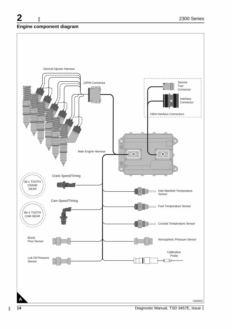
Engine component diagram
A HA0002
OEM Interface Connectors
36-1 TOOTH CRANK GEAR
36+1 TOOTH CAM GEAR
12PIN Connector
Internal Injector Harness
Main Engine Harness
Lub Oil Pressure Sensor
Boost Pres Sensor
Crank Speed/Timing
Cam Speed/Timing
Atmospheric Pressure Sensor
Service Tool Connector
Interface Connector
Calibration Probe
Cooolat Temperature Sensor
Fuel Temperature Sensor
Inlet Manifold TemperatureSensor
2
Diagnostic Manual, TSD 3457E, Issue 1 15
2300 Series
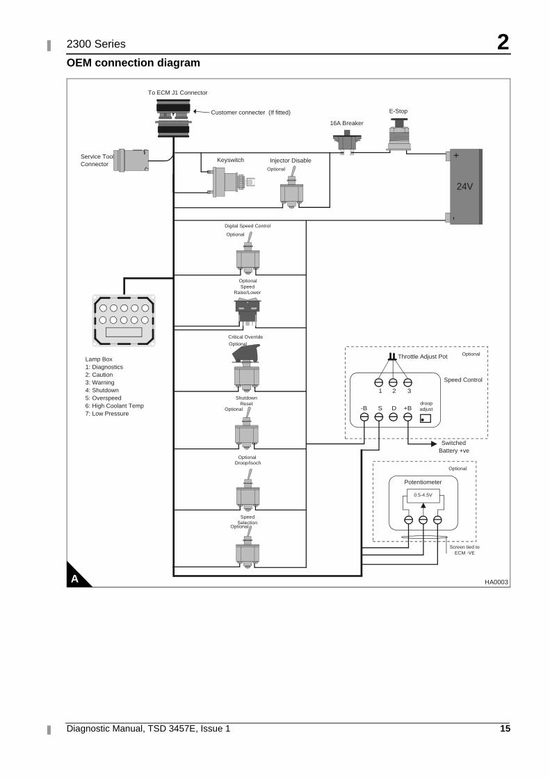
OEM connection diagram
A
16A Breaker
KeyswitchOptional
1
droopadjust
2 3
-B S D +B
Throttle Adjust Pot
Speed Control
Optional
SwitchedBattery +ve
Potentiometer
0.5-4.5V
Optional
Lamp Box1: Diagnostics2: Caution3: Warning4: Shutdown5: Overspeed6: High Coolant Temp7: Low Pressure
E-Stop
Optional
Optional
Optional
Screen tied toECM -VE
Service ToolConnector
+-
24V
To ECM J1 Connector
Injector Disable
Customer connecter (If fitted)
Digital Speed Control
Optional
SpeedRaise/Lower
Optional
SpeedSelection
Critical Override
Optional
ShutdownReset
Droop/Isoch
HA0003
2
16 Diagnostic Manual, TSD 3457E, Issue 1
2300 Series
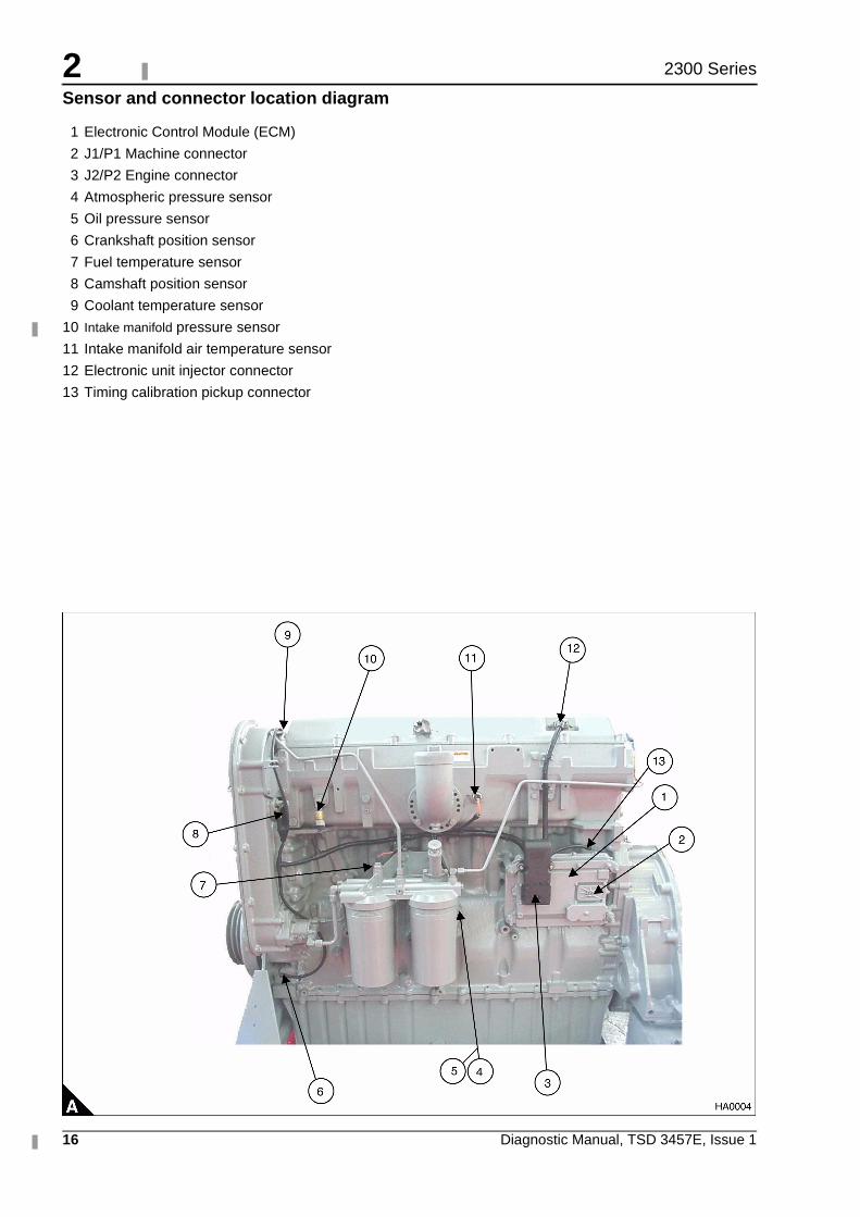
Sensor and connector location diagram
1 Electronic Control Module (ECM)
2 J1/P1 Machine connector
3 J2/P2 Engine connector
4 Atmospheric pressure sensor
5 Oil pressure sensor
6 Crankshaft position sensor
7 Fuel temperature sensor
8 Camshaft position sensor
9 Coolant temperature sensor
10 Intake manifold pressure sensor
11 Intake manifold air temperature sensor
12 Electronic unit injector connector
13 Timing calibration pickup connector
2
Diagnostic Manual, TSD 3457E, Issue 1 17
2300 Series
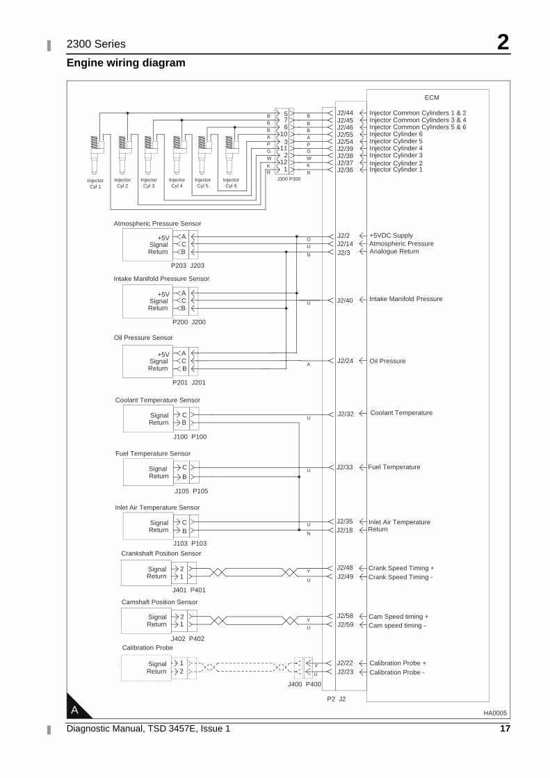
Engine wiring diagram
A HA0005
ECM
J2/44 Injector Common Cylinders 1 & 2
Injector Cyl 1
Injector Cyl 2
Injector Cyl 3
Injector Cyl 4
Injector Cyl 5
Injector Cyl 6
J2/45 J2/46 J2/55 J2/54 J2/39 J2/38 J2/37 J2/36
Injector Common Cylinders 3 & 4 Injector Common Cylinders 5 & 6 Injector Cylinder 6 Injector Cylinder 5 Injector Cylinder 4 Injector Cylinder 3 Injector Cylinder 2 Injector Cylinder 1
5 7 6
10 3
11 2
12 1
J300 P300
A C
+5V Signal
B Return
A C
+5V Signal
B Return
A C
+5V Signal
B Return
Atmospheric Pressure Sensor
J2/2 J2/14 J2/3
J2/24
J2/32
J2/33
J2/35
J2/40
Intake Manifold Pressure Sensor
Oil Pressure Sensor
J2/18
+5VDC Supply
Analogue Return
Fuel Temperature
Inlet Air Temperature Return
Inlet Air Temperature Sensor
C Signal B Return
Coolant Temperature Sensor
C Signal B Return
Fuel Temperature Sensor
C Signal B Return
Atmospheric Pressure
Intake Manifold Pressure
Oil Pressure
Coolant Temperature
J2/48 J2/49 Crank Speed Timing -
2 Signal 1 Return
Crankshaft Position Sensor
Crank Speed Timing +
Cam speed timing -
Camshaft Position Sensor
Cam Speed timing + J2/58 J2/59
2 Signal 1 Return
J2/22 J2/23 2
Signal 1 Return
Calibration Probe
Calibration Probe + Calibration Probe -
P2 J2
P203 J203
P200 J200
P201 J201
J100 P100
J105 P105
J103 P103
J401 P401
J402 P402
J400 P400
B
B B
A
P G
W
K
R
O
U
N
U
A
U
U
U
N
Y
U
Y
U
Y
U
B
B B A
P
W
G
K R
2
18 Diagnostic Manual, TSD 3457E, Issue 1
2300 Series
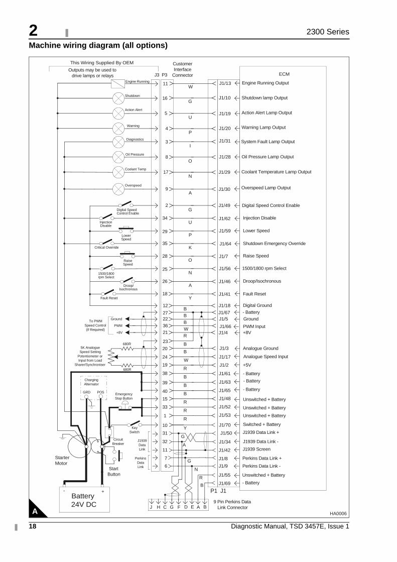
Machine wiring diagram (all options)
A HA0006
Digital Speed Control Enable
9 Pin Perkins Data Link Connector
Outputs may be used to drive lamps or relays
Action Alert
Warning
Diagnostics
Oil Pressure
Coolant Temp
Overspeed
Injection Disable
Lower Speed
Critical Override
Raise Speed
1500/1800 rpm Select
Droop/ Isochronous
Fault Reset
PWM
Ground
+8V
To PWM Speed Control (If Required)
ECM
J1/19
J1/20
J1/31
Action Alert Lamp Output
Warning Lamp Output
System Fault Lamp Output
J1/28 Oil Pressure Lamp Output
J1/29 Coolant Temperature Lamp Output
J1/30 Overspeed Lamp Output
J1/49
J1/62
J1/59
J1/64
J1/7
J1/56
J1/46
J1/41
J1/18
J1/66
J1/5
J1/4
Digital Speed Control Enable
Injection Disable
Lower Speed
Shutdown Emergency Override
Raise Speed
1500/1800 rpm Select
Droop/Isochronous
Fault Reset
Digital Ground
PWM Input
Ground
+8V
5
4
3
8
17
9
2
34
29
35
28
25
26
18
12
36
22
21
27 J1/67 - Battery
D E
Key Switch
Circuit Breaker
Starter Motor
Start Button
Emergency Stop Button
5K Analogue Speed Setting
Potentiometer or Input from Load
Sharer/Synchroniser
A B G F C
Battery 24V DC
+ -
H J
Unswitched + Battery
Unswitched + Battery
Unswitched + Battery
P1 J1
J1/61 - Battery
- Battery J1/63
J1/65
J1/52
J1/53
J1/48
J1/70 Switched + Battery
- Battery
J1/3
J1/17
J1/2
Analogue Ground
Analogue Speed Input
+5V
J1/50
J1/34
J1/42
J1939 Data Link +
J1939 Data Link -
J1939 Screen
J1/8 Perkins Data Link +
J1/9 Perkins Data Link -
J1/55
J1/69
Unswitched + Battery
- Battery
20
24
19
38
39
40
15
33
1
10
31
32
11
J1939 Data Link
23
Charging Alternator
GRD POS
7
6
Perkins Data Link
U
P
I
O
N
A
G
U
P
K
O
N
A
Y
B B
B
W
R
B
B
W
R
B
B
B
R
R
R
Y
G
A
G
N
R
B
680R
680R
Customer Interface
Connector
This Wiring Supplied By OEM
J3 P3
Shutdown J1/10 Shutdown lamp Output 16 G
J1/13 Engine Running Output 11 W
Engine Running
2
Diagnostic Manual, TSD 3457E, Issue 1 19
2300 Series
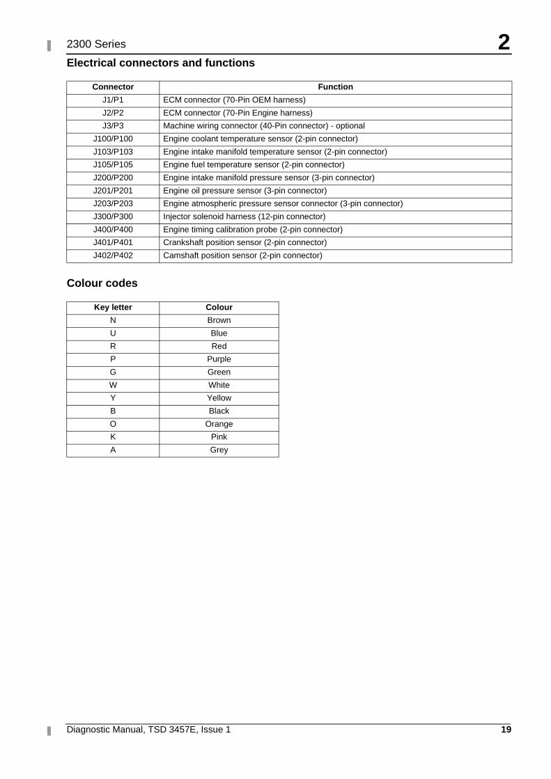
Electrical connectors and functions
Colour codes
Connector Function
J1/P1 ECM connector (70-Pin OEM harness)
J2/P2 ECM connector (70-Pin Engine harness)
J3/P3 Machine wiring connector (40-Pin connector) - optional
J100/P100 Engine coolant temperature sensor (2-pin connector)
J103/P103 Engine intake manifold temperature sensor (2-pin connector)
J105/P105 Engine fuel temperature sensor (2-pin connector)
J200/P200 Engine intake manifold pressure sensor (3-pin connector)
J201/P201 Engine oil pressure sensor (3-pin connector)
J203/P203 Engine atmospheric pressure sensor connector (3-pin connector)
J300/P300 Injector solenoid harness (12-pin connector)
J400/P400 Engine timing calibration probe (2-pin connector)
J401/P401 Crankshaft position sensor (2-pin connector)
J402/P402 Camshaft position sensor (2-pin connector)
Key letter Colour
N Brown
U Blue
R Red
P Purple
G Green
W White
Y Yellow
B Black
O Orange
K Pink
A Grey
2
20 Diagnostic Manual, TSD 3457E, Issue 1
2300 Series
Service tools and diagnostics
The Perkins TIPSS-EST service tool is designed to help the service technician analyse and locate faults or problems within the system. They are required to perform calibrations and to read or change engine parameters.
Perkins TIPSS-EST is a software program that runs on a personal computer and requires a communication adapter to translate information from the Perkins Data Link to the computer RS232 port.
Perkins TIPSS-EST can be used to display the following information:
� Programmable parameter settings
� Active and logged diagnostic codes
� Logged events
� Engine rating history
� Histograms
� Custom data
� ECM date/time clock
Perkins TIPSS-EST can also be used to perform the following functions:
� Diagnostic tests
� Sensor calibrations
� Flash programming
� Parameter programming
� Copy configuration (ECM replacement)
� Data logging
� Real time graphing
There are several adapter cables, breakout T cables, etc that are used in order to access measurements of signals. A heavy duty multimeter is suitable in order to make the necessary measurements. A multimeter that has the ability to measure duty cycle may also be required. Other special tools include those needed to measure pressure and temperature. For further details refer to Chapter 5, Special tools.
A diagnostic code reader is also available. This is a hand held unit which allows reading certain parameters and diagnostic codes.
Diagnostic Manual, TSD 3457E, Issue 1 21
32300 Series
Programming parameters 3
Connecting the TIPSS-EST
The communications adapter is powered by 24 Volts DC from the engine battery. This permits operation beside the engine to allow use during engine operation.
Use the following procedures to connect the service tool to the engine.
1 Stop the engine by turning the key switch to the OFF position.
2 Connect the service tool harness cable on the engine to the communication adapter. Refer "Connecting TIPSS-EST using a TIPSS communication adapter" on page 22.
3 Connect the communication adapter to the PC using the appropriate cable.
4 Turn the key switch to the ON position in order to begin testing. The service tool will operate while the engine is running or with the engine OFF and the key switch ON. If the tool does not communicate with the ECM disconnect and reconnect the diagnostics connector cable. Check the communication. If the problem is still present refer to Test 45: Perkins Data Link circuit test on page 118.
Notes:� The service tool may restart during engine cranking due to a voltage dip on the battery line.
� The TIPSS-EST must be configured to communicate with the specific type of communication adapter used. Go to the "Preferences" menu that is located under "Utilities" in order to select the appropriate communication adapter.
3
22 Diagnostic Manual, TSD 3457E, Issue 1
2300 Series
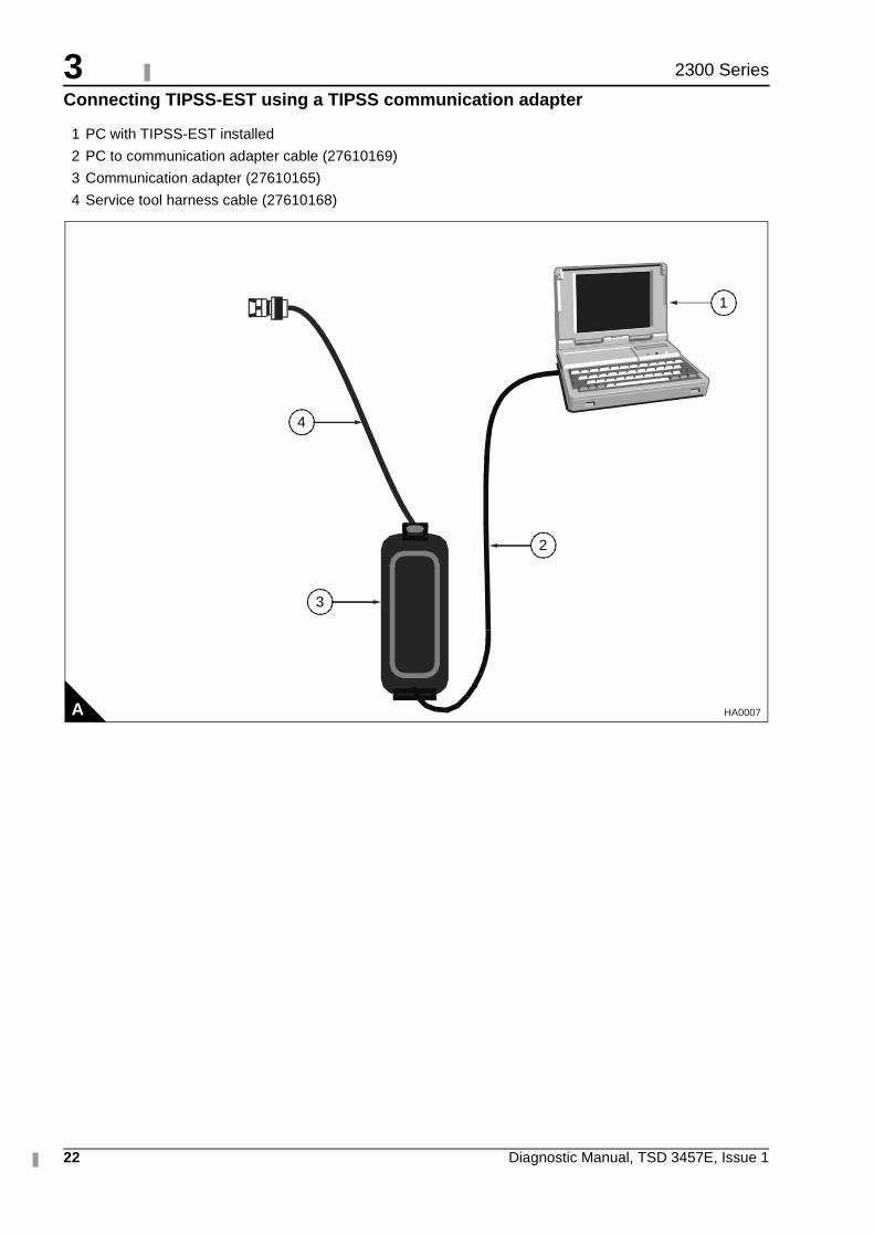
Connecting TIPSS-EST using a TIPSS communication adapter
1 PC with TIPSS-EST installed
2 PC to communication adapter cable (27610169)
3 Communication adapter (27610165)
4 Service tool harness cable (27610168)
A
1
2
4
3
HA0007
3
Diagnostic Manual, TSD 3457E, Issue 1 23
2300 Series
Passwords
Factory passwords
Factory passwords are required to perform each of the following functions:
1 Program a new ECM
When an ECM is replaced the system configuration parameters must be programmed into the new ECM. A new ECM will allow these parameters to be programmed once without factory passwords. After the initial programming these parameters are protected by factory passwords.
2 Rerate to another engine family
This requires changing the ECM software code, which is protected by factory passwords.
3 Read customer passwords
If the owner loses his customer passwords, he will not be able to program customer parameters. By using factory passwords, one can read customer passwords, then use those customer passwords to program customer parameters.
4 Clear certain diagnostic codes
Diagnostic code 253-02 Incorrect ECM software requires a factory password to clear the code. This diagnostic code should be cleared only if you are certain that the ECM software is for the specific engine.
Caution: Operating the engine with ECM software not designed for that engine will result in engine damage. Be sure the ECM software is correct for your engine.
5 Certain other codes require customer passwords. The majority of logged codes do not require passwords to be cleared. To obtain factory passwords, proceed as if you already have the password. At some point, if the factory passwords are actually needed, TIPSS-EST will request the factory passwords and display the information required to obtain the passwords.
Customer passwords
If customer passwords have been entered, they are then required to change ANY customer parameter.
TIPSS-EST can be used to change customer parameters. To obtain customer passwords, contact the supplier of the equipment. If the owner has lost the passwords, customer passwords may be read by using TIPSS-EST (factory passwords are required in order to read customer passwords) by using the following procedure.
1 In TIPSS-EST access "Passwords" under the "Information" menu.
2 When the "Factory Password" screen appears, record the information listed.
3 Obtain the factory passwords. The information recorded above must be provided, and generates a permanent record at Perkins of the access.
4 From the "Factory Password" screen, enter the factory passwords.
5 When the "View Customer Passwords" screen appears, record the customer passwords. The customer passwords may then be used to change customer parameters.
3
24 Diagnostic Manual, TSD 3457E, Issue 1
2300 Series
Programming a new ECM
The Engine Control Module or ECM is the brain of the system. When a problem occurs, it is easy to assume that the ECM is responsible. This is usually the wrong conclusion.
Most failures occur at the wiring and connectors or at a sensor input/output. Follow the diagnostic test procedures and do not replace an ECM on speculation.
However, when your diagnosis indicates that a failure has in fact occurred in the ECM, the following procedure outlines the steps required to replace a faulty ECM.
Note: If an ECM replacement is required, the ECM parameters and injector trim codes can be transferred from the suspect ECM to the replacement ECM. This feature requires TIPSS-EST and is only possible if the suspect ECM can communicate with the TIPSS-EST.
Replacing the ECM using TIPSS-EST ECM replacement feature
Note: The Test ECM referred to below is another identical ECM to that fitted to the engine. There is no special Test ECM available.
1 Ensure that the ECM is the problem by first temporarily connecting a test ECM. Hang the test ECM on the side of the engine. Flash program the identical software that was used in the suspect ECM into the test ECM. Use the TIPSS-EST ECM replacement feature to copy the parameter configuration of the suspect ECM into the test ECM. Ensure that the parameters in the test ECM are programmed the same as the parameters in the suspect one.
2 If the test ECM repairs the problem, reconnect the suspect ECM. Check that the problem returns when the suspect ECM is reconnected.
3 Select the ECM Replacement feature under the "Service/Copy Configuration" menu and load the parameters from the failed ECM.
4 Temporarily connect the new ECM by connecting both ECM connectors. Do not mount the ECM on the engine yet.
5 Flash program the ECM software into the new ECM if the software is not already installed.
Note: The new ECM may be shipped with no software installed or may have been pre-flashed at the factory. Following reflashing the engine may be inoperable until a factory password has been obtained.
6 Use the TIPSS-EST ECM replacement feature to program the new ECM
7 Enter rating number parameter into the new ECM
8 Check for active codes. Program any required parameters that have not been programmed.
Note: On initial power-up of a new ECM, the Rating Number parameter must be programmed to avoid a 268-02 Check Programmable Parameters diagnostic code.
Install the new ECM on the engine and after checking for correct operation perform a timing calibration.
3
Diagnostic Manual, TSD 3457E, Issue 1 25
2300 Series
Replacing the ECM (if ECM replacement feature cannot be used)
1 Ensure that the ECM is the problem by first temporarily connecting a test ECM. Hang the test ECM on the side of the engine. Flash program the identical software that was used in the suspect ECM into the test ECM. Program any parameters that are necessary to use the ECM for the test. Program the parameters exactly the same as they are in the suspect ECM.
2 If the test ECM repairs the problem, reconnect the suspect ECM. Check that the problem returns when the suspect ECM is reconnected.
3 Obtain customer parameters from the failed ECM
Obtain and record the customer passwords. If the customer has lost or forgotten their passwords, obtain factory passwords to get them.
Use TIPSS-EST to access customer specified parameters from the ECM that is being replaced. If the ECM does not communicate with the electronic service tool, obtain the required parameter list from the OEM.
Record the customer parameters.
4 Record ECM current totals
5 Temporarily connect the new ECM by connecting both ECM connectors. Do not mount the ECM to the engine until the timing calibration has been performed.
6 Flash program the software into the new ECM if the software is not already installed.
Note: The new ECM may be shipped with no software installed, or may have been pre-flashed at the factory.
7 Obtain factory passwords if required. The following parameters can be programmed once on a new ECM without factory passwords:
� Full Load Setting (FLS)
� Full Torque Setting (FTS)
� Engine serial number
System configuration parameters must be entered before the customer specified parameters are entered
If customer parameters are entered before the system configuration parameters, the total tattletale will change. It will then be necessary to obtain another set of factory passwords in order to access system configuration parameters.
8 Record the following information from the engine information plate:
� Engine serial number
Obtain the following information from the factory:
� Full Load Setting (FLS)
� Full Torque Setting (FTS)
� Injector Trim Codes
Use TIPSS-EST to access system configuration parameters. When the "Factory Specified Passwords" screen appears record the following information:
� ECM serial number
� Engine serial number
� TIPSS-EST serial number
� Total tattletale
� Reason code
Leave TIPSS-EST on the "Factory Specified Passwords" screen and obtain the factory passwords.
Continued
3
26 Diagnostic Manual, TSD 3457E, Issue 1
2300 Series
9 Program the new ECM
� On initial powerup of a new ECM the following three parameters must be programmed to avoid a 268-02 Check Programmable Parameters diagnostic code:
� Full Load Setting (FLS)
� Full Torque Setting (FTS)
� Engine serial number
Use TIPSS-EST to access system configuration parameters. Enter the recorded values for the following parameters:
� Full Load Setting (FLS)
� Full Torque Setting (FTS)
� Engine serial number
� Injector trim codes
Use TIPSS-EST to access customer specified parameters. Enter the customer specified parameters and the original customer passwords.
Use TIPSS-EST to access current totals from the "Read/Change Current Totals" main menu. Using the recorded factory passwords enter the totals from the original ECM.
Use the "Service\Calibrations\Timing Calibration" menu to calibrate the timing. Refer to Test 46: Engine speed/timing circuit test on page 126.
10 Install the new ECM on the engine.
3
Diagnostic Manual, TSD 3457E, Issue 1 27
2300 Series
Programming an ECM using flash programming
1 Connect the PC to the appropriate communication adapter and connect the communication adapter to the ECM. Refer to "Connecting TIPSS-EST using a TIPSS communication adapter" on page 22.
2 Start the WinFlash PC Program.
3 Ensure that the key switch is ON and the engine is OFF.
4 Select the part number of the engine software that needs to be programmed into the ECM and proceed with programming. A new ECM is shipped with no software loaded.
Note: The WinFlash PC program provides the ECM, application and software part number of the selected file. Ensure that this file matches the engine before you begin to Flash the file into the ECM
PC program software messages and their meaning
A new ECM comes unprogrammed. An unprogrammed ECM will prompt you for all three of the following messages. The information that is contained in the ECM Status will be scrambled and meaningless if the module has not been programmed previously (this is normal).
Message: The engine ID in the flash file does not match the engine ID in the ECM
Meaning: The ECM has software for a different engine.
Solution: Stop the transfer and access information about the ECM Status under the "Electronic Control Module" menu. Ensure that the file you are about to transfer matches the engine application.
Message: The application ID in the flash file does not match the application ID in the ECM
Meaning: The ECM has software for a different application.
Solution: Stop the transfer and access information about the ECM Status under the "Electronic Control Module" menu. Ensure that the file you are about to transfer is for the correct engine type.
Message: The ID of the ECM in the flash file does not match the ID of the ECM in the ECM
Meaning: The ECM is not for use with this application.
Solution: Stop the transfer and access information about the ECM status under the "Electronic Control Module" menu. Ensure that the ECM on the engine is for the correct application.
Note: If you access the ECM status under the "Engine Control Module" menu, but do not program the ECM, complete the following procedure.
Turn the key switch to the OFF position, and then to the ON position before using TIPSS-EST. If the key switch is not cycled after reading the ECM Status, the ECM will not communicate with your service tool or will not start.
Cycling the key switch is not necessary after the software has been successfully programmed using the WinFlash program.
5 Start the engine and check for correct operation.
Program any parameters not previously in the old software if a 268-02 Check Programmable Parameters diagnostic code is active. Read the diagnostic code from service tool "Active Diagnostic Code" screen in order to determine the parameter(s) requiring programming.
On initial powerup of a new ECM three parameters must be programmed to avoid a 268-02 Check Programmable Parameters diagnostic code:
� Full Load Setting (FLS)
� Full Torque Setting (FTS)
� Engine serial number
Refer to "Programming a new ECM" on page 24.
3
28 Diagnostic Manual, TSD 3457E, Issue 1
2300 Series
ECM date/time clock
ECM date/time stamped information
The ECM date and time can be programmed with the TIPSS-EST service tool (factory passwords are required to change these parameters). This will display the programmed date in month/day/year format and the programmed time in hour:minute:second format. The tool has the option to program any date/time or automatically select the date/time stored in the PC real time clock.
The date and time will remain programmed in the ECM even if the unswitched battery connections are removed.
The ECM Date/time clock is used to stamp the following critical event codes:
� 360-3 Low oil pressure Shutdown
� 361-3 High coolant temperature Shutdown
Before adjusting the ECM date/time clock
Before adjusting the ECM date/time clock, ask the owner/operator if the time stamped information should be recorded. After the time stamped information is recorded, clear this information before adjusting the ECM date/time clock. This is a very important step if the adjustment of the clock is a big adjustment. This will prevent unnecessary confusion if someone else views the information at a later date.
Determining time stamped information occurrence
When viewing time stamped information remember that someone may have incorrectly or never set the clock.
Use the time currently set in the ECM to compare any ECM recorded information to the time the ECM indicates to determine how long ago the time stamped event occurred.
Caution: Do not replace an ECM because of an incorrect time.
The following example indicates the correct use of the clock.
Example use of ECM date/time stamped information
The TIPSS-EST service tool indicates a Low Oil Pressure occurred on NOV 19 1998 10:30:46 and that the current time of day in the ECM is NOV 24 1998 11:20:58.
This indicates that the problem occurred approximately 5 days and 50 minutes ago.
Caution: Do not compare it to the current time at your location.
If the ECM time is significantly different than your current time, for example the wrong month is programmed, ensure you have recorded the time stamped information if it is important. After recording the information, clear the code and then adjust the clock.
3
Diagnostic Manual, TSD 3457E, Issue 1 29
2300 Series
ECM diagnostic clock
The diagnostic clock should not be confused with the ECM date/time clock. The diagnostic clock records the actual hours the ECM has been powered (key switch ON and engine running). This information is maintained even if the unswitched battery connections are removed. The clock information is used to log diagnostic code and event code occurrences. Logged diagnostic codes and event codes display the diagnostic clock hour of the first and last occurrence and the total number of occurrences.
Note: Actual engine running hours (total time) can be obtained from the "Current Totals" menu of TIPSS-EST.
Injector codes
Injector codes are etched on each injector. The injector codes can be viewed/changed using TIPSS-EST by selecting the "Calibrations" screen under the "Service" menu. The injector codes calibration is located under the "Calibration" menu. The injector code must match the code on the corresponding injector. When an injector is replaced, reprogram the new code for the new injector.
TIPSS-EST cylinder cut-out test
The 2300 and 2800 Series engines use electronic fuel injectors. These injectors are mechanically actuated and electronically energized. The cylinder cut-out tests are used to confirm that the cylinders are functioning correctly.
The cylinder cut-out test allows a specific cylinder to be cut out while the fuel position is monitored for the remaining cylinders.
To perform a cylinder cut-out test, connect TIPSS-EST to the diagnostic connector as described in "Connecting the TIPSS-EST" on page 21, and select the Cylinder cut-out test located under the "Diagnostics" menu.
The Cylinder cut-out test opens with the manual test. At the bottom of the TIPSS-EST screen there is a row of buttons that function as follows:
� Change toggles the highlighted cylinder between powered and not powered
� Power All returns all cylinders to the normal operating state
� Start initiates the automated Cylinder cut-out test.
� Stop terminates the automated test.
� Results displays the test results.
� Print allows the contents of the screen to be previewed or to be sent to a file or printer.
Programming parameters
Many programmable parameters affect engine operation. These parameters may be changed by using the TIPSS-EST service tool. The parameters are stored in the ECM. Whilst any parameter can be read, passwords can be used to protect parameters from unauthorized changes.
Two categories contain these various parameters:
System configuration parameters
System configuration parameters can only be altered with factory passwords by using TIPSS-EST.
Customer specified parameters
Customer specified parameters can be changed by using the TIPSS-EST service tool (this may require customer passwords if customer passwords have been programmed). Refer to "Passwords" on page 13 for more details on how to receive and use factory and customer passwords.
3
30 Diagnostic Manual, TSD 3457E, Issue 1
2300 Series
System configuration parameters
System configuration parameters affect critical settings for the engine. They are programmed at the factory and would normally never need to be changed through the life of the engine. A complete list of these parameters is given in the table on the following page.
Note: System Configuration Parameters must be reprogrammed if an ECM is replaced. Failure to programme these parameters will result in a 268-02 Check Programmable Parameters diagnostic code.
Proper values for these parameters are stamped on the engine information ratings plate located on the valve cover or air inlet manifold. Factory passwords are required to change these parameters. The following information is a description of the system configuration parameters.
Full Load Setting (FLS)
Number representing fuel system adjustment made at the factory to “fine tune” the fuel system. The correct value for this parameter is stamped on the engine information ratings plate. A new ECM requires this parameter to be programmed to avoid generating a 268-02 Check Programmable Parameters diagnostic code.
Full Torque Setting (FTS)
Similar to Full Load Setting. This parameter must be programmed to avoid generating a 268-02 Check Programmable Parameters diagnostic code.
Software part number
This is the part number of the software flashed into the ECM.
Engine serial number
This should be programmed to match the engine serial number that is stamped on the engine information plate. A new ECM is delivered without the engine serial number programmed.
ECM serial number
This is a read-only parameter which displays the serial number of the ECM.
Software release date
This parameter is defined by the ECM software and is not programmable. It is used to provide the version of the software. Customer parameters software changes can be tracked by this date. The date is provided in the month and year (NOV99), where NOV is the month (November) and 99 is the year (1999).
Critical override switch installed
The critical override switch, if fitted and enabled, allows the engine to continue running even if engine oil pressure or coolant temperature have reached the limits where the engine would normally be shutdown. If the engine is run in this condition, the engine warranty is void and any events occurring are stored in the ECM with time and date stamping. Implementation of this facility requires a factory password.
Total tattletale
Displays the total number of times the configuration parameters have been changed.
3
Diagnostic Manual, TSD 3457E, Issue 1 31
2300 Series
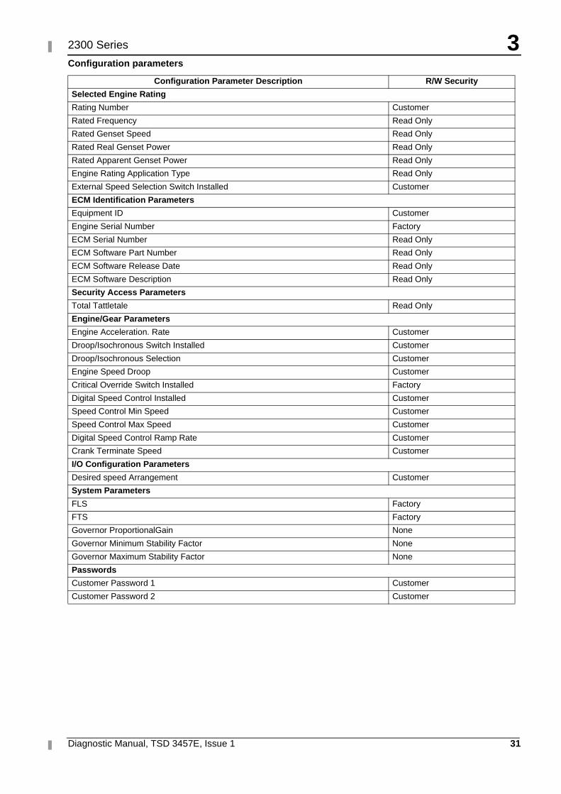
Configuration parameters
Configuration Parameter Description R/W Security
Selected Engine Rating
Rating Number Customer
Rated Frequency Read Only
Rated Genset Speed Read Only
Rated Real Genset Power Read Only
Rated Apparent Genset Power Read Only
Engine Rating Application Type Read Only
External Speed Selection Switch Installed Customer
ECM Identification Parameters
Equipment ID Customer
Engine Serial Number Factory
ECM Serial Number Read Only
ECM Software Part Number Read Only
ECM Software Release Date Read Only
ECM Software Description Read Only
Security Access Parameters
Total Tattletale Read Only
Engine/Gear Parameters
Engine Acceleration. Rate Customer
Droop/Isochronous Switch Installed Customer
Droop/Isochronous Selection Customer
Engine Speed Droop Customer
Critical Override Switch Installed Factory
Digital Speed Control Installed Customer
Speed Control Min Speed Customer
Speed Control Max Speed Customer
Digital Speed Control Ramp Rate Customer
Crank Terminate Speed Customer
I/O Configuration Parameters
Desired speed Arrangement Customer
System Parameters
FLS Factory
FTS Factory
Governor ProportionalGain None
Governor Minimum Stability Factor None
Governor Maximum Stability Factor None
Passwords
Customer Password 1 Customer
Customer Password 2 Customer
3
32 Diagnostic Manual, TSD 3457E, Issue 1
2300 Series
Customer specified parameters
Customer specified parameters allow the OEM to modify engine parameters to suit the application.
Customer parameters may be changed repeatedly as a customer changes his requirements. Customer passwords are required to change these parameters.
The following information is a brief description of the customer specified parameters.
Rating duty selection
This enables selection of the engine rating from a series of maps within the ECM. Changing the rating requires a customer password. The available ratings within the ECM will vary with engine type and specification.
Rated frequency
This displays the rated frequency of the set, i.e. 50 Hz or 60 Hz, determined by the rating selection and the status of the external speed selection switch. This parameter is read only.
Rated speed
This displays the rated speed of the engine, i.e. 1500 rev/min or 1800 rev/min, determined by the rating selection and the status of the external speed selection switch. This parameter is read only.
Rated real genset power
This displays the maximum power in kW of the currently selected rating. This parameter is read only.
Rated apparent genset power
This displays the maximum power in kVA of the currently selected rating. This parameter is read only.
Rating configuration
This displays the configuration of the currently selected rating. The possible configurations are:
� Standby power
� Limited time prime power
� Prime power
� Continuous or baseload power
For definitions of these ratings, refer to ISO8528. This parameter is read only.
Note: Not all of the above rating configurations will be available in a given ECM software file.
External speed selection switch enable
For dual speed (1500 rev/min or 1800 rev/min) applications, where an external speed selection switch is required, this parameter enables the functionality of the speed selection switch within the software. Changing this parameter requires a customer password.
Engine startup acceleration rate
Enables the acceleration rate of the engine in rev/min/s, from idle speed to rated speed, to be programmed. Control of this parameter enables any overshoot in speed on start up to be limited. Changing this parameter requires a customer password.
Droop/isochronous switch enable
Determines whether the external droop/isochronous switch is enabled or disabled. Changing this parameter requires a customer password.
Droop/isochronous selection
The engine will normally be run in isochronous mode i.e. the engine speed is the same at all loads. For certain applications where parallel operation with another generating set or with the grid is required, it is necessary for stability reasons to run in droop condition where engine speed drops with load. This parameter enables droop/isochronous running selection. Changing this parameter requires a customer password.
Note: If an external droop/isochronous switch is enabled, the position of this switch will over-ride the Droop/Isochronous selection.
3
Diagnostic Manual, TSD 3457E, Issue 1 33
2300 Series
Engine speed droop
If droop operation is selected, this parameter allows the setting of percentage droop i.e. the percentage that the engine speed will drop with load. This parameter has no effect when the engine is running in isochronous mode. Changing this parameter requires a customer password.
Digital speed control installed
This parameter determines whether raise/lower switch input control of engine speed is installed. If digital speed control is not installed, speed control reverts to the analogue or PWM inputs depending on which input is selected via the desired speed input configuration detailed on the following page. Changing this parameter requires a customer password.
Digital speed control min speed
This setting determines the minimum speed range of both the raise/lower button control and the analogue control, for example: if this is set to 100 rev/min and the nominal engine speed is selected for 1500 rev/min, the minimum speed setting is 1400 rev/min. It does not affect the PWM speed control range which has fixed min/max limits. Changing this parameter requires a customer password.
Digital speed control max speed
This setting determines the maximum speed range of both the raise/lower button control and the analogue control, i.e. if this is set to 100 rev/min and the nominal engine speed is selected for 1500 rev/min, the maximum speed setting is 1600 rev/min. It does not affect the PWM speed control range which has fixed min/max limits. Changing this parameter requires a customer password.
Digital speed control ramp rate
This setting determines the rate of change of engine speed in rev/min/s when the raise/lower switch inputs are closed. Changing this parameter requires a customer password.
Crank terminate speed
This parameter is used to set the engine speed at which the crank terminate relay output will be switched. Changing this parameter requires a customer password.
Desired speed input arrangement
This parameter allows selection of the analogue or PWM external speed control if the digital speed control is not installed. The Analogue or PWM speed control inputs are normally used with generating set load sharing and synchronising controllers. Changing this parameter requires a customer password.
Note: If PWM or Analogue speed control is selected but there are no inputs to the selected speed control terminals, the engine will default to running at 1100 rev/min.
If it is not intended to use PWM or analogue speed control then the Digital speed control should be selected.
Governor gain parameters
The adjustable Governor Gain parameters are:
� Governor Gain Factor
� Governor Minimum Stability Factor
� Governor Maximum Stability
Notes:� No engineering units associated with these numbers.
� The programmable range is wide for flexibility. The values are valid from 1- 40000. This wide programmable range may not be fully used on any system. Do not expect to use the whole range.
3
34 Diagnostic Manual, TSD 3457E, Issue 1
2300 Series
Gain explanations
Governor gain factor
The governor gain factor is multiplied to the difference between desired speed and actual speed.
� If the governor gain factor value is too large, the engine speed can overshoot the desired speed. The overshoot is caused by an overcorrection or a steady state instability.
� If the governor gain factor is too small, the response necessary to accelerate the engine to the desired speed must be obtained by ramping the stability terms to a higher value. This process is time consuming so, as a result, the engine speed is slow to respond.
Governor minimum/maximum stability factor
The stability factor terms work to eliminate a steady state speed error. There are two gain terms used for stability. If the error is greater than 20 rev/min and the error is increasing, then the maximum stability gain is functioning. If the error is less than 20 rev/min, then the minimum stability gain is used. This function allows the use of a high gain that would otherwise cause the engine to be unstable when the engine is operating near the desired speed.
� If either the minimum stability gain or the maximum stability gain is set too high, the governor will provide more fuel than is necessary to bring the error to zero. The additional fuel will cause the engine speed to overshoot and ring.
� If either the minimum stability gain or the maximum stability gain is set too low, the engine will take too long to arrive at a steady state speed.
Tuning procedure
1 Turn the key switch to the OFF/RESET position. Connect the TIPSS-EST service tool and check that engine overspeed protection is enabled before beginning the tuning process. Engine overspeed is configured on the "Service\Monitoring System" screen on TIPSS-EST.
Warning! Performing engine governor tuning without engine overspeed protection could result in serious engine damage. Ensure that this parameter is ON while performing this procedure.
2 Start the engine. Observe, on the engine mounted genset control panel, that the engine has reached rated speed. This panel will serve as the speed reference point during this procedure.
3 Enter the "Configuration Parameters" screen on TIPSS-EST.
4 Determine the desired scenario to tune the engine. For example, is the engine having poor response during specific load assignments or specific load dumps ?
5 Perform the desired load change from step 4. Observe the response of the engine by viewing the engine speed on the genset mounted control panel, by looking at the system bus frequency response to the load change, or by listening to the response of the engine.
6 Use the suggestions listed above to determine which gains should be adjusted.
Note: Usually, the governor gain factor should be somewhat lower that the governor minimum stability factor for optimum performance. The maximum stability factor is typically a smaller value than the minimum stability gain and governor gain factor.
7 Repeat steps 5,6, and 7 until a desired engine response can be met. Use large adjustments (10% of original gain) at first to generally tune the engine in the proper manner. As the response is closer to desired, increase the gains in smaller increments (1% of total gain).
Customer password 1, customer password 2
These are the customer password programmable parameters that can be used to protect certain configuration parameters from unauthorised changes.
Diagnostic Manual, TSD 3457E, Issue 1 35
42300 Series
Fault diagnosis 4
Introduction
This chapter has information that will assist with the diagnosis of mechanical and electronic faults on the engine, and its management system.
The diagnostic process
Some engine symptoms are caused by conditions or components other than the electronic control system, such as poor fuel quality or incorrectly adjusted valves.
The basic philosophy of diagnosing this engine is to follow the three steps listed below FIRST to diagnose a malfunctioning engine:
1 Gather operator information. Check that the fault is not due to normal engine operation.
2 Perform a visual inspection of the engine. Check fuel and oil level, supply and/or condition. Check for visible wiring and connector problems or damaged components.
3 Check and repair all ACTIVE/LOGGED diagnostic codes using the diagnostic procedures given in "Diagnostic procedures with a diagnostic fault code" on page 76.
If ALL three of these inspections reveal no problems, identify probable causes using the procedure or procedures in this chapter that best describes the symptoms. Narrow the probable causes given in the procedure by considering operator information, operating conditions, and repair history of the engine.
Operator information
� What happened, and when ?
� Under what conditions ?
� Was the engine rev/min (speed) high or low ?
� Was the engine under load ?
� Are there any customer or dealer installed systems that could cause this symptom ?
� What else occurred ?
� When did the symptoms begin (and what else happened at that time) ?
Logged diagnostic codes
� Do they correlate to probable causes ?
� Did they occur at the same time as the symptoms ?
� Are some codes logged repeatedly ?
Other symptoms
� Are they related to this symptom ?
� Do they have common probable causes ?
Finally, test each probable cause using the tests suggested by the procedure
Be sure to check connectors, especially on intermittent problems. Refer to Test 39: Inspecting electrical connectors on page 82 for details.
4
36 Diagnostic Manual, TSD 3457E, Issue 1
2300 Series
Diagnostic procedures without a diagnostic fault code
General information
This section is to be used for diagnosing problems that have symptoms but do not have ACTIVE diagnostic codes.
Before using this section, be sure that you have gathered information about the fault to adequately describe the symptoms, verified that the fault is not due to normal engine operation and repaired all ACTIVE diagnostic codes. Refer to "Diagnostic procedures with a diagnostic fault code" on page 76.
4
Diagnostic Manual, TSD 3457E, Issue 1 37
2300 Series
Diagnostic symptoms
Engine will not crank Test 1
Note: This is NOT an electronic system problem, the engine starter motor wiring is not supplied by Perkins. Refer to the Workshop Manual and OEM Manual for additional information on the following tests.
Probable root causes
� Battery cables/batteries
� Emergency stop switch
� Starter motor solenoid or circuit problem (in system wiring)
� Starter motor/flywheel ring gear
� Engine accessory
� Hydraulic cylinder lock
� Internal engine problem
Perform the following tests
1 Check battery post and battery cables for loose connections and corrosion. If corroded, remove and clean cables and connections. Check the optional battery disconnect switch.
2 Check that the optional emergency stop switch is not engaged. Load test batteries. If necessary, charge the batteries.
3 Test starter motor solenoid operation. Check the system wiring to starter motor solenoid.
4 Test starter motor operation. Inspect starter motor pinion and ring gear for damage.
5 Check that the timing pin was not left in the flywheel housing after setting valve clearances. Use the engine turning tool and attempt to manually turn the engine. If unable to turn the engine, remove and inspect engine accessories that can lock up the engine. Repair or renew as necessary.
6 Remove injectors and check for fluid in the cylinders.
7 Disassemble engine to inspect for internal components that may be seized, broken, bent, out of alignment, etc. Refer to the Workshop Manual.
4
38 Diagnostic Manual, TSD 3457E, Issue 1
2300 Series
Engine cranks but will not start Test 2
Probable root causes
� Starting aids/fuel waxing (cold temperature operation)
� Electrical connectors and wiring
� ECM software or ECM
� Engine speed/timing signal
� Electrical connections to the unit injector solenoids
� Fuel supply
� Restriction of the air supply or exhaust
� Combustion problem
Perform the following tests
1 If cold ambient conditions exist, check operation of starting aids. Check the coolant immersion heater for malfunction and replace if required. Check for presence of congealed fuel (wax). Repair as required.
2 Check that the keyswitch and Injection Disable switches are closed.
3 Check for correct installation of the ECM connectors J1/P1 and J2/P2, engine speed/timing sensor connectors J401/P401 and J402/P402, and unit injector connectors J300/P300. Check that the ECM is receiving the correct voltage.
Note: Aftermarket engine protection devices may interrupt power to the ECM and prevent communications with the TIPSS-EST service tool. Check for correct installation and operation of aftermarket engine protection devices. Aftermarket devices may need to be bypassed to continue.
4 If the engine has an unprogrammed ECM it will crank but will not start. Access ECM Status in the WinFlash PC program and follow the request to program the software. Refer to "Programming an ECM using flash programming" on page 27. Failure to program the software will cause the engine to not start or communicate. Cycling the key switch will allow access to the WinFlash PC program.
5 Check that none of the diagnostic lamps are illuminated. If any are, turn the key switch OFF and ON to try and clear the fault. If the diagnostic lamps cannot be cleared refer to "Diagnostic procedures with a diagnostic fault code" on page 76. Check that the speed/timing sensors are correctly installed and that no diagnostic codes are active.
6 Check that there is not an active 268-02 Check Programmable Parameters diagnostic code. If the diagnostic code is present, refer to "Programming an ECM using flash programming" on page 27.
7 Observe the engine speed on the TIPSS-EST "Status" screen while cranking the engine. If the electronic service tool displays 0 rev/min while cranking the engine, there is a problem in the engine speed/timing sensor circuit. Refer to Test 46: Engine speed/timing circuit test on page 126.
If the engine speed is greater than 50 rev/min the engine speed/timing circuitry appears to be operating correctly. Check that the timing reference gear is installed correctly and keyed to the camshaft by means of the locating dowel. If the gear was installed backwards or flipped over during assembly, the engine will not start.
8 Check the calibration of the timing sensor and recalibrate if required. Refer to Test 47: Engine speed/timing calibration on page 134. Check for correct orientation between crankshaft and camshaft drive gears, repair as required.
9 Ensure the unit injector connectors are correctly installed. Refer to Test 48: Injector solenoids circuit test on page 138 and perform the Injector Solenoid test as a quick check to confirm that the ECM can energize the unit injector solenoids. Ensure that the injection disable switch (if fitted) is ON.
10 Check for a fuel supply problem and check fuel pressure. Refer to Test 29: Engine has a fuel supply problem on page 65.
11 Check for combustion problems.
4
Diagnostic Manual, TSD 3457E, Issue 1 39
2300 Series
Engine misfires, runs rough or is unstable Test 3
Note: If the problem is intermittent and cannot be recreated, refer to Test 6: Intermittent low power or power cut-outs on page 42. If the problem is consistent and can be recreated, continue with this procedure.
Probable root causes
� Cold mode operation (normal operation, if the problem occurs only after start-up)
� Battery cables, battery
� Electrical connections to the ECM
� Loss of backup engine speed/timing sensor
� Throttle position signal
� Faulty electronic unit injector circuit (individual cylinder malfunction)
� Fuel supply
� Air inlet or exhaust restrictions or air system leaks
� Internal engine problem
Note: If the problem only occurs under certain conditions (high engine speed, full load or engine operating temperature, etc), then perform the test under those operating conditions.
Perform the following tests
1 Check indicator lamps; refer to Test 39: Inspecting electrical connectors on page 82.
2 Check for a fuel supply problem and check fuel pressure.
3 Check air inlet and exhaust systems for restrictions and leaks. Look for a diagnostic lamp indication, or tripped restriction indicators (if fitted) associated with plugged air filters. Replace plugged air filters, or clean filters, as described in the User’s Handbook, and repair any leaks found. Also refer to Test 41: Analogue sensor open or short circuit test on page 91. Refer to the Workshop Manual if an internal engine problem is suspected.
4 Monitor the TIPSS-EST "Status" screen to check that the engine has exited cold mode and observe the coolant temperature reading on the electronic service tool. The engine should exit cold mode operation whenever the coolant temperature is above 17 °C (64 °F) and the engine has been running for five minutes.
5 Check battery post and battery cables for loose connections and corrosion. If corroded, remove and clean cables and connections.
6 Check the ECM connectors J1/P1 and J2/P2, customer connector, engine speed/timing sensor connectors, unit injector connectors and associated wiring for damage, abrasion or incorrect attachment. Refer to Test 39: Inspecting electrical connectors on page 82.
7 Check the battery connection at the customer connector and ECM connector. Perform a pull test on the customer connector. Perform a pull test on P1 pins 48, 52, 53, 61, 63, 65 and 70. The wires should remain in the connectors during pull test. Refer to Test 39: Inspecting electrical connectors on page 82.
8 Check that a 190-11 Loss of Engine Speed Signal diagnostic code is not active. If the 190-11 code is active check to see if a 342-11 Loss of Backup Engine Speed Sensor diagnostic code has been recently logged. If the electronic service tool indicates that a 342-11 code has been recently logged perform a pull test on the wires to the backup engine speed/timing sensor. Refer to Test 39: Inspecting electrical connectors on page 82. If a 342-11 code has not been recently logged and the 190-11 code is active refer to Test 46: Engine speed/timing circuit test on page 126.
9 Connect an electronic service tool to the service tool connector. Turn the key switch to the ON position, engine OFF. If a PWM speed control is fitted, check that a 91-08 Invalid PWM Speed Control Signal diagnostic code has not been recently logged. Monitor the throttle position from low idle to full throttle.
10 Check for active or recently logged injector solenoid diagnostic codes. Use an electronic service tool and cut out each cylinder at low idle to isolate the misfiring cylinder(s). Refer to Test 48: Injector solenoids circuit test on page 138.
4
40 Diagnostic Manual, TSD 3457E, Issue 1
2300 Series
Low power/poor or no response to throttle Test 4
Probable root causes
� Customer specified parameters
� Cold mode operation (normal operation if the problem occurs only after start-up in cold weather)
� Engine is in a derated mode
� Electrical connections to the ECM
� External speed control
� Faulty electronic unit injector (individual cylinder malfunction)
� Fuel supply
� Intake manifold sensor signal
� Air inlet or exhaust system restrictions or leaks
� Incorrect adjustment of full load setting or full torque setting
Note: If the problem only occurs under certain conditions (high engine speed, full load or engine operating temperature, etc), then perform the test under those operating conditions.
Perform the following tests
1 Check for a fuel supply problem and check fuel pressure. Refer to Test 29: Engine has a fuel supply problem on page 65.
2 Check air inlet and exhaust systems for restrictions and leaks. Look for a diagnostic lamp indication, or tripped restriction indicators (if fitted) associated with plugged air filters. Replace plugged air filters, or clean filters, as described in the User’s Handbook, and repair any leaks found.
3 Check that the fault is not normal (programmed parameter) operation. Connect an electronic service tool and check the system/customer parameters. If a 268-02 Check Customer Or System Parameters diagnostic code is active, ensure ALL the system and customer parameters are programmed. Check that the injector codes are programmed. Check that the correct rating is programmed.
4 Monitor the electronic service tool "Status" screen to check that the engine has exited cold mode. Observe the coolant temperature reading on the electronic service tool. The engine should exit cold mode operation whenever the coolant temperature is above 17 °C (64 °F) and the engine has been running for five minutes.
5 The engine may be derated due to altitude or other factors. Connect an electronic service tool and check for active engine derates or diagnostic codes.
6 Check the ECM connectors J1/P1 and J2/P2, customer connector and the relevant speed setting inputs and associated wiring for damage, abrasion or incorrect attachment. Refer to Test 39: Inspecting electrical connectors on page 82.
7 If a PWM speed control is fitted, connect an electronic service tool to the service tool connector. Turn the key switch to the ON position, engine OFF. Check that a 91-08 Invalid PWM Speed Control Signal diagnostic code has not been recently logged. Monitor the PWM input. The duty cycle should be between 5 and 10 percent at low load and increase at full load. If the throttle position change is erratic or out of range the problem is with the external speed control.
8 Check that a 262-03 +5 V Supply Above Normal or a 262-04 +5 V Supply Below Normal diagnostic code is not present. If either of the codes are active refer to Test 41: Analogue sensor open or short circuit test on page 91.
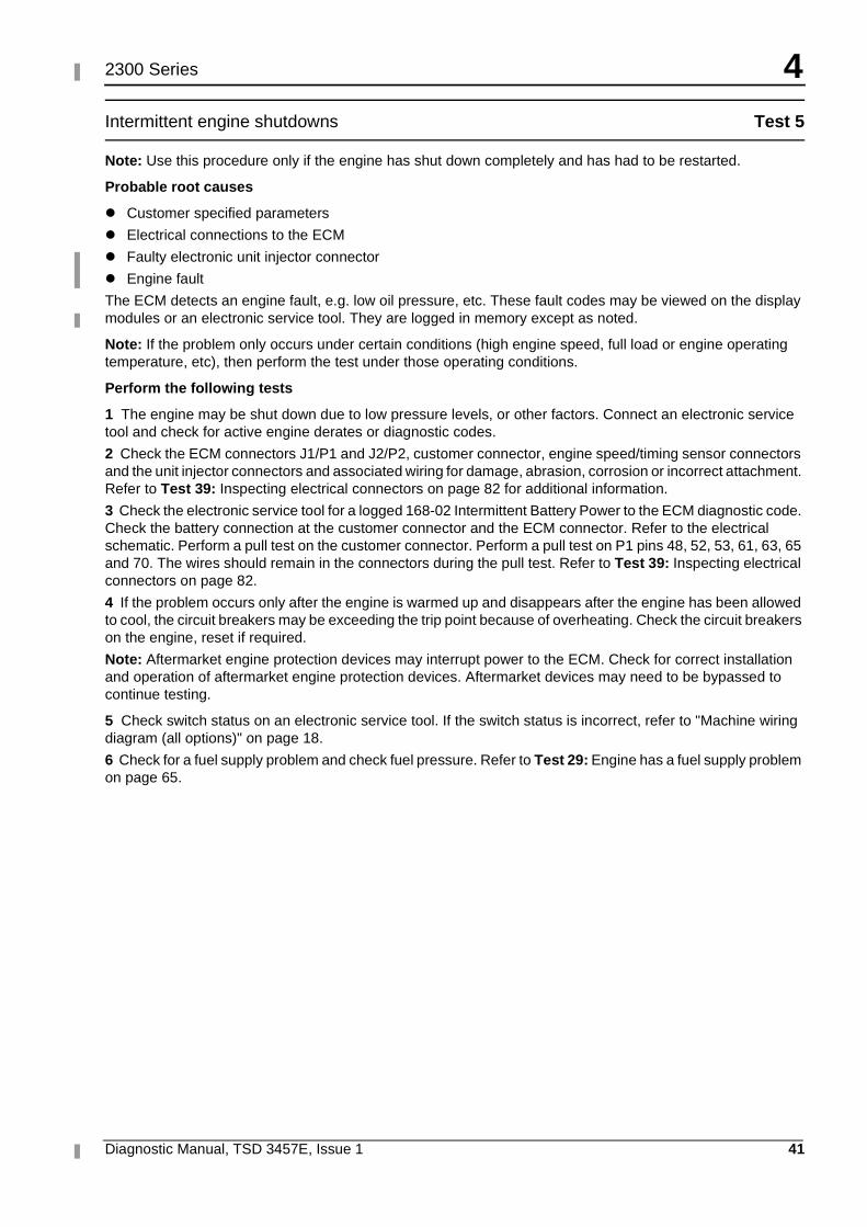
4
Diagnostic Manual, TSD 3457E, Issue 1 41
2300 Series
Intermittent engine shutdowns Test 5
Note: Use this procedure only if the engine has shut down completely and has had to be restarted.
Probable root causes
� Customer specified parameters
� Electrical connections to the ECM
� Faulty electronic unit injector connector
� Engine fault
The ECM detects an engine fault, e.g. low oil pressure, etc. These fault codes may be viewed on the display modules or an electronic service tool. They are logged in memory except as noted.
Note: If the problem only occurs under certain conditions (high engine speed, full load or engine operating temperature, etc), then perform the test under those operating conditions.
Perform the following tests
1 The engine may be shut down due to low pressure levels, or other factors. Connect an electronic service tool and check for active engine derates or diagnostic codes.
2 Check the ECM connectors J1/P1 and J2/P2, customer connector, engine speed/timing sensor connectors and the unit injector connectors and associated wiring for damage, abrasion, corrosion or incorrect attachment. Refer to Test 39: Inspecting electrical connectors on page 82 for additional information.
3 Check the electronic service tool for a logged 168-02 Intermittent Battery Power to the ECM diagnostic code. Check the battery connection at the customer connector and the ECM connector. Refer to the electrical schematic. Perform a pull test on the customer connector. Perform a pull test on P1 pins 48, 52, 53, 61, 63, 65 and 70. The wires should remain in the connectors during the pull test. Refer to Test 39: Inspecting electrical connectors on page 82.
4 If the problem occurs only after the engine is warmed up and disappears after the engine has been allowed to cool, the circuit breakers may be exceeding the trip point because of overheating. Check the circuit breakers on the engine, reset if required.
Note: Aftermarket engine protection devices may interrupt power to the ECM. Check for correct installation and operation of aftermarket engine protection devices. Aftermarket devices may need to be bypassed to continue testing.
5 Check switch status on an electronic service tool. If the switch status is incorrect, refer to "Machine wiring diagram (all options)" on page 18.
6 Check for a fuel supply problem and check fuel pressure. Refer to Test 29: Engine has a fuel supply problem on page 65.
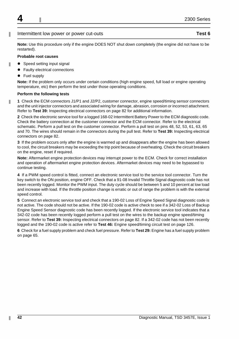
4
42 Diagnostic Manual, TSD 3457E, Issue 1
2300 Series
Intermittent low power or power cut-outs Test 6
Note: Use this procedure only if the engine DOES NOT shut down completely (the engine did not have to be restarted).
Probable root causes
� Speed setting input signal
� Faulty electrical connections
� Fuel supply
Note: If the problem only occurs under certain conditions (high engine speed, full load or engine operating temperature, etc) then perform the test under those operating conditions.
Perform the following tests
1 Check the ECM connectors J1/P1 and J2/P2, customer connector, engine speed/timing sensor connectors and the unit injector connectors and associated wiring for damage, abrasion, corrosion or incorrect attachment. Refer to Test 39: Inspecting electrical connectors on page 82 for additional information.
2 Check the electronic service tool for a logged 168-02 Intermittent Battery Power to the ECM diagnostic code. Check the battery connection at the customer connector and the ECM connector. Refer to the electrical schematic. Perform a pull test on the customer connector. Perform a pull test on pins 48, 52, 53, 61, 63, 65 and 70. The wires should remain in the connectors during the pull test. Refer to Test 39: Inspecting electrical connectors on page 82.
3 If the problem occurs only after the engine is warmed up and disappears after the engine has been allowed to cool, the circuit breakers may be exceeding the trip point because of overheating. Check the circuit breakers on the engine, reset if required.
Note: Aftermarket engine protection devices may interrupt power to the ECM. Check for correct installation and operation of aftermarket engine protection devices. Aftermarket devices may need to be bypassed to continue testing.
4 If a PWM speed control is fitted, connect an electronic service tool to the service tool connector. Turn the key switch to the ON position, engine OFF. Check that a 91-08 Invalid Throttle Signal diagnostic code has not been recently logged. Monitor the PWM input. The duty cycle should be between 5 and 10 percent at low load and increase with load. If the throttle position change is erratic or out of range the problem is with the external speed control.
5 Connect an electronic service tool and check that a 190-02 Loss of Engine Speed Signal diagnostic code is not active. The code should not be active. If the 190-02 code is active check to see if a 342-02 Loss of Backup Engine Speed Sensor diagnostic code has been recently logged. If the electronic service tool indicates that a 342-02 code has been recently logged perform a pull test on the wires to the backup engine speed/timing sensor. Refer to Test 39: Inspecting electrical connectors on page 82. If a 342-02 code has not been recently logged and the 190-02 code is active refer to Test 46: Engine speed/timing circuit test on page 126.
6 Check for a fuel supply problem and check fuel pressure. Refer to Test 29: Engine has a fuel supply problem on page 65.
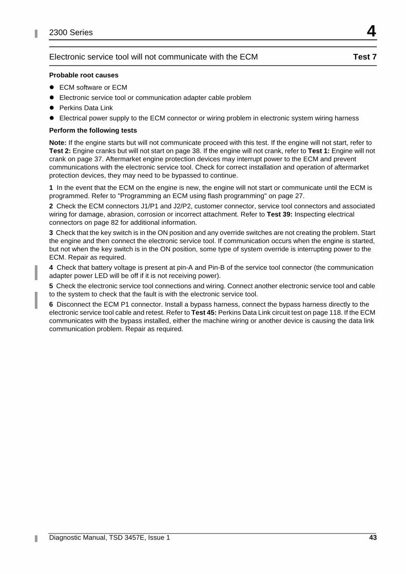
4
Diagnostic Manual, TSD 3457E, Issue 1 43
2300 Series
Electronic service tool will not communicate with the ECM Test 7
Probable root causes
� ECM software or ECM
� Electronic service tool or communication adapter cable problem
� Perkins Data Link
� Electrical power supply to the ECM connector or wiring problem in electronic system wiring harness
Perform the following tests
Note: If the engine starts but will not communicate proceed with this test. If the engine will not start, refer to Test 2: Engine cranks but will not start on page 38. If the engine will not crank, refer to Test 1: Engine will not crank on page 37. Aftermarket engine protection devices may interrupt power to the ECM and prevent communications with the electronic service tool. Check for correct installation and operation of aftermarket protection devices, they may need to be bypassed to continue.
1 In the event that the ECM on the engine is new, the engine will not start or communicate until the ECM is programmed. Refer to "Programming an ECM using flash programming" on page 27.
2 Check the ECM connectors J1/P1 and J2/P2, customer connector, service tool connectors and associated wiring for damage, abrasion, corrosion or incorrect attachment. Refer to Test 39: Inspecting electrical connectors on page 82 for additional information.
3 Check that the key switch is in the ON position and any override switches are not creating the problem. Start the engine and then connect the electronic service tool. If communication occurs when the engine is started, but not when the key switch is in the ON position, some type of system override is interrupting power to the ECM. Repair as required.
4 Check that battery voltage is present at pin-A and Pin-B of the service tool connector (the communication adapter power LED will be off if it is not receiving power).
5 Check the electronic service tool connections and wiring. Connect another electronic service tool and cable to the system to check that the fault is with the electronic service tool.
6 Disconnect the ECM P1 connector. Install a bypass harness, connect the bypass harness directly to the electronic service tool cable and retest. Refer to Test 45: Perkins Data Link circuit test on page 118. If the ECM communicates with the bypass installed, either the machine wiring or another device is causing the data link communication problem. Repair as required.
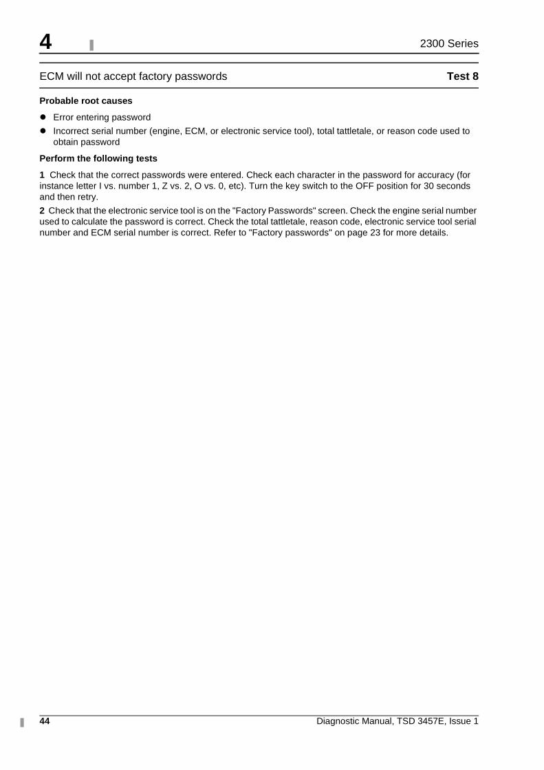
4
44 Diagnostic Manual, TSD 3457E, Issue 1
2300 Series
ECM will not accept factory passwords Test 8
Probable root causes
� Error entering password
� Incorrect serial number (engine, ECM, or electronic service tool), total tattletale, or reason code used to obtain password
Perform the following tests
1 Check that the correct passwords were entered. Check each character in the password for accuracy (for instance letter I vs. number 1, Z vs. 2, O vs. 0, etc). Turn the key switch to the OFF position for 30 seconds and then retry.
2 Check that the electronic service tool is on the "Factory Passwords" screen. Check the engine serial number used to calculate the password is correct. Check the total tattletale, reason code, electronic service tool serial number and ECM serial number is correct. Refer to "Factory passwords" on page 23 for more details.
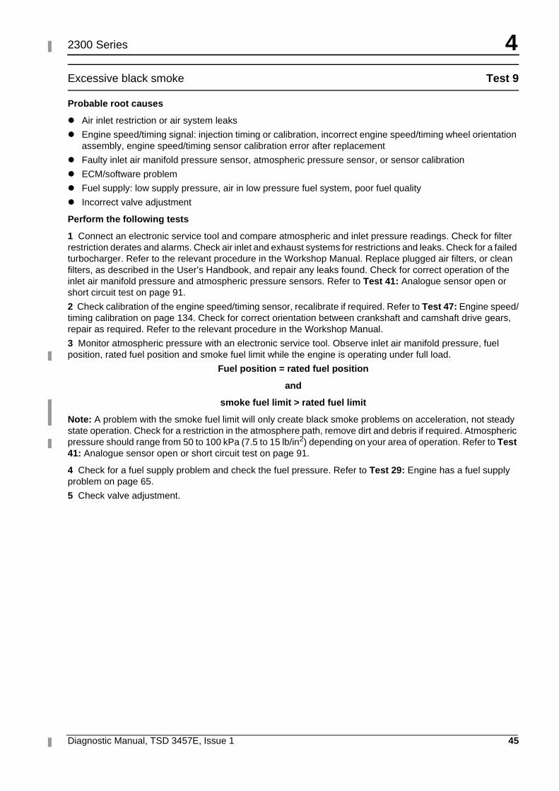
4
Diagnostic Manual, TSD 3457E, Issue 1 45
2300 Series
Excessive black smoke Test 9
Probable root causes
� Air inlet restriction or air system leaks
� Engine speed/timing signal: injection timing or calibration, incorrect engine speed/timing wheel orientation assembly, engine speed/timing sensor calibration error after replacement
� Faulty inlet air manifold pressure sensor, atmospheric pressure sensor, or sensor calibration
� ECM/software problem
� Fuel supply: low supply pressure, air in low pressure fuel system, poor fuel quality
� Incorrect valve adjustment
Perform the following tests
1 Connect an electronic service tool and compare atmospheric and inlet pressure readings. Check for filter restriction derates and alarms. Check air inlet and exhaust systems for restrictions and leaks. Check for a failed turbocharger. Refer to the relevant procedure in the Workshop Manual. Replace plugged air filters, or clean filters, as described in the User’s Handbook, and repair any leaks found. Check for correct operation of the inlet air manifold pressure and atmospheric pressure sensors. Refer to Test 41: Analogue sensor open or short circuit test on page 91.
2 Check calibration of the engine speed/timing sensor, recalibrate if required. Refer to Test 47: Engine speed/timing calibration on page 134. Check for correct orientation between crankshaft and camshaft drive gears, repair as required. Refer to the relevant procedure in the Workshop Manual.
3 Monitor atmospheric pressure with an electronic service tool. Observe inlet air manifold pressure, fuel position, rated fuel position and smoke fuel limit while the engine is operating under full load.
Fuel position = rated fuel position
and
smoke fuel limit > rated fuel limit
Note: A problem with the smoke fuel limit will only create black smoke problems on acceleration, not steady state operation. Check for a restriction in the atmosphere path, remove dirt and debris if required. Atmospheric pressure should range from 50 to 100 kPa (7.5 to 15 lb/in2) depending on your area of operation. Refer to Test 41: Analogue sensor open or short circuit test on page 91.
4 Check for a fuel supply problem and check the fuel pressure. Refer to Test 29: Engine has a fuel supply problem on page 65.
5 Check valve adjustment.
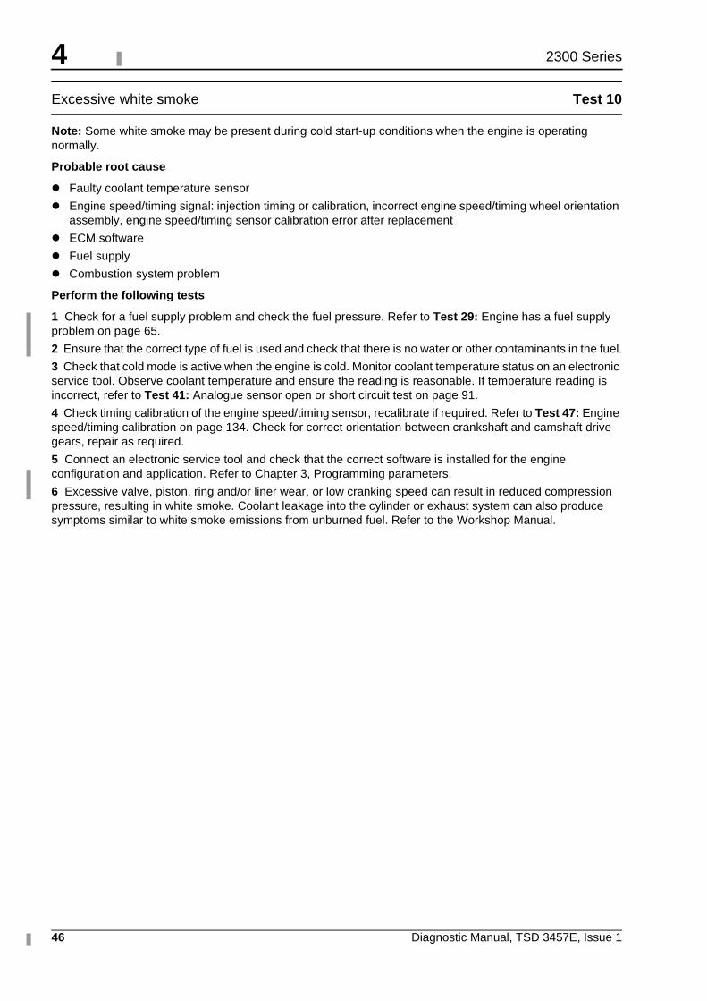
4
46 Diagnostic Manual, TSD 3457E, Issue 1
2300 Series
Excessive white smoke Test 10
Note: Some white smoke may be present during cold start-up conditions when the engine is operating normally.
Probable root cause
� Faulty coolant temperature sensor
� Engine speed/timing signal: injection timing or calibration, incorrect engine speed/timing wheel orientation assembly, engine speed/timing sensor calibration error after replacement
� ECM software
� Fuel supply
� Combustion system problem
Perform the following tests
1 Check for a fuel supply problem and check the fuel pressure. Refer to Test 29: Engine has a fuel supply problem on page 65.
2 Ensure that the correct type of fuel is used and check that there is no water or other contaminants in the fuel.
3 Check that cold mode is active when the engine is cold. Monitor coolant temperature status on an electronic service tool. Observe coolant temperature and ensure the reading is reasonable. If temperature reading is incorrect, refer to Test 41: Analogue sensor open or short circuit test on page 91.
4 Check timing calibration of the engine speed/timing sensor, recalibrate if required. Refer to Test 47: Engine speed/timing calibration on page 134. Check for correct orientation between crankshaft and camshaft drive gears, repair as required.
5 Connect an electronic service tool and check that the correct software is installed for the engine configuration and application. Refer to Chapter 3, Programming parameters.
6 Excessive valve, piston, ring and/or liner wear, or low cranking speed can result in reduced compression pressure, resulting in white smoke. Coolant leakage into the cylinder or exhaust system can also produce symptoms similar to white smoke emissions from unburned fuel. Refer to the Workshop Manual.
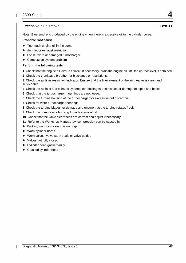
4
Diagnostic Manual, TSD 3457E, Issue 1 47
2300 Series
Excessive blue smoke Test 11
Note: Blue smoke is produced by the engine when there is excessive oil in the cylinder bores.
Probable root cause
� Too much engine oil in the sump
� Air inlet or exhaust restriction
� Loose, worn or damaged turbocharger
� Combustion system problem
Perform the following tests
1 Check that the engine oil level is correct. If necessary, drain the engine oil until the correct level is obtained.
2 Check the crankcase breather for blockages or restrictions.
3 Check the air filter restriction indicator. Ensure that the filter element of the air cleaner is clean and serviceable.
4 Check the air inlet and exhaust systems for blockages, restrictions or damage to pipes and hoses.
5 Check that the turbocharger mountings are not loose.
6 Check the turbine housing of the turbocharger for excessive dirt or carbon.
7 Check for worn turbocharger bearings.
8 Check the turbine blades for damage and ensure that the turbine rotates freely.
9 Check the compressor housing for indications of oil.
10 Check that the valve clearances are correct and adjust if necessary.
11 Refer to the Workshop Manual; low compression can be caused by:
� Broken, worn or sticking piston rings
� Worn cylinder bores
� Worn valves, valve stem seals or valve guides
� Valves not fully closed
� Cylinder head gasket faulty
� Cracked cylinder head
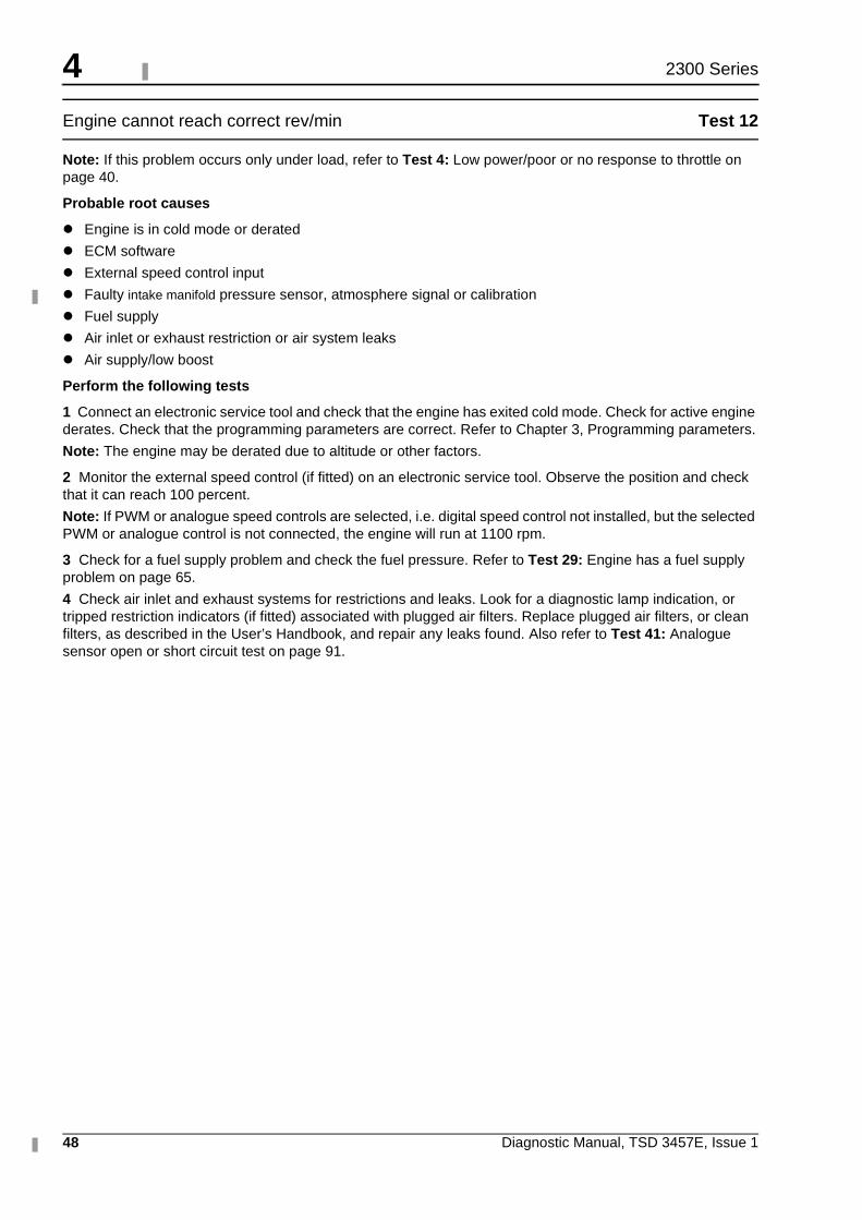
4
48 Diagnostic Manual, TSD 3457E, Issue 1
2300 Series
Engine cannot reach correct rev/min Test 12
Note: If this problem occurs only under load, refer to Test 4: Low power/poor or no response to throttle on page 40.
Probable root causes
� Engine is in cold mode or derated
� ECM software
� External speed control input
� Faulty intake manifold pressure sensor, atmosphere signal or calibration
� Fuel supply
� Air inlet or exhaust restriction or air system leaks
� Air supply/low boost
Perform the following tests
1 Connect an electronic service tool and check that the engine has exited cold mode. Check for active engine derates. Check that the programming parameters are correct. Refer to Chapter 3, Programming parameters.
Note: The engine may be derated due to altitude or other factors.
2 Monitor the external speed control (if fitted) on an electronic service tool. Observe the position and check that it can reach 100 percent.
Note: If PWM or analogue speed controls are selected, i.e. digital speed control not installed, but the selected PWM or analogue control is not connected, the engine will run at 1100 rpm.
3 Check for a fuel supply problem and check the fuel pressure. Refer to Test 29: Engine has a fuel supply problem on page 65.
4 Check air inlet and exhaust systems for restrictions and leaks. Look for a diagnostic lamp indication, or tripped restriction indicators (if fitted) associated with plugged air filters. Replace plugged air filters, or clean filters, as described in the User’s Handbook, and repair any leaks found. Also refer to Test 41: Analogue sensor open or short circuit test on page 91.
4
Diagnostic Manual, TSD 3457E, Issue 1 49
2300 Series
Poor acceleration or response Test 13
Probable root causes
� The engine is in cold mode or a derate mode.
� ECM software
� External speed control input
� Incorrect intake manifold pressure sensor or atmosphere signal
� Air inlet or exhaust restriction or leaks
� Fuel supply
Perform the following tests
1 Connect an electronic service tool. Check that the engine has exited cold mode operation. The engine will not respond as fast until it has warmed to operating temperature.
2 Check that the correct ECM software is installed. Refer to Chapter 3, Programming parameters.
3 Monitor the external speed control input on an electronic service tool. Observe position and check that the reading is stable and can reach 100 percent.
4 Inspect ECM connectors J1/P1 and J2/P2, engine interface connectors, and the unit injector connectors for correct connection. Repair or replace as required. Refer to Test 39: Inspecting electrical connectors on page 82. Perform the cylinder cut-out test to check for any non-operable unit injectors, and replace only those diagnosed as faulty by the cylinder cut-out check. Connect an electronic service tool and cut-out each cylinder to isolate the misfiring cylinder(s). If results are inconclusive, perform the test under load or shut off half of the engine’s cylinders and repeat cut-out on the remaining active cylinders to locate those misfiring. If it can be isolated to a specific cylinder(s), refer to Test 48: Injector solenoids circuit test on page 138.
5 Monitor atmospheric pressure with an electronic service tool. Observe intake manifold pressure while the engine is operating under full load. Atmospheric pressure should range from 50 to 100 kPa (7.5 to 15 lb/in2).
6 Check air inlet and exhaust systems for restrictions and leaks. Look for a warning lamp or diagnostic lamp indication, or tripped restriction indicators (if fitted) associated with plugged air filters. Replace plugged air filters, or clean filters, as described in the User’s Handbook, and repair any leaks found.
7 Check for a fuel supply problem and check the fuel pressure. Refer to Test 29: Engine has a fuel supply problem on page 65.
4
50 Diagnostic Manual, TSD 3457E, Issue 1
2300 Series
Poor fuel consumption Test 14
Note: This is NOT an electronic system problem. Refer to the Workshop Manual for additional information on the following tests.
Probable root causes
� Incorrect engine operation
� Engine speed/timing signal: injection timing or calibration, incorrect engine speed/timing wheel orientation, engine speed/timing sensor calibration error after replacement
� Faulty electronic unit injector(s) (individual cylinder malfunction)
� Fuel supply
� Air inlet or exhaust restrictions or air system leaks
Perform the following tests
1 Check timing calibration of engine speed/timing sensor and recalibrate if required. Refer to Test 47: Engine speed/timing calibration on page 134. Check for correct orientation between crankshaft and camshaft drive gears, repair as required. Refer to the Workshop Manual.
2 Inspect ECM connector J2/P2 and the unit injector connector for correct connection. Refer to Test 39: Inspecting electrical connectors on page 82. Connect an electronic service tool and cut out each cylinder to isolate the misfiring cylinder(s). If results are inconclusive, shut off half of the engine’s cylinders and repeat cut-out on remaining active cylinders to locate those that are misfiring. Refer to Test 48: Injector solenoids circuit test on page 138.
3 Check for a fuel supply problem and check the fuel pressure. Refer to Test 29: Engine has a fuel supply problem on page 65.
4 Check air inlet and exhaust systems for restrictions and leaks. Look for a warning lamp or diagnostic lamp indication, or tripped restriction indicators (fitted) associated with plugged air filters. Replace plugged air filters, or clean filters, as described in the User’s Handbook, and repair any leaks found.
4
Diagnostic Manual, TSD 3457E, Issue 1 51
2300 Series
Too much vibration Test 15
Note: This is NOT an electronic system problem. Refer to the Workshop Manual for additional information on the following tests.
Possible root causes
� Loose or faulty vibration damper
� Engine supports are loose, wrong or are incorrectly torqued
� Equipment may not be in alignment or is out of balance
� Engine misfiring or running rough
Perform the following tests
1 Check vibration damper for damage. Tighten bolts. If vibration damper bolt holes have damage or wear, replace with new parts. Install a new vibration damper if necessary.
2 Run the engine through its speed range while looking for loose or broken mounts or brackets. Tighten all mounting bolts. Install new components if necessary.
3 Check alignment and balance, correct if required.
4 Refer to Test 3: Engine misfires, runs rough or is unstable on page 39.
4
52 Diagnostic Manual, TSD 3457E, Issue 1
2300 Series
Noise coming from cylinder Test 16
Note: This is NOT an electronic system problem. Refer to the Workshop Manual for additional information on the following tests.
Probable root causes
� Low quality fuel
� Incorrect fuel injection timing calibration
� Faulty electronic unit injector(s)
� Incorrect valve train operation or valve train noise (clicking)
� Damage to valve spring(s) or locks
� Not enough lubrication
� Loud tapping sound from rocker cover
� Damage to valve(s)
� Unit injector plunger
� Damaged camshaft lobe
� Little or no valve clearance, worn valve seat or face of valve
Perform the following tests
1 Check for a fuel supply problem and check the fuel pressure. Refer to Test 29: Engine has a fuel supply problem on page 65.
2 Check and calibrate electronic injection timing with an electronic service tool. Refer to Test 47: Engine speed/timing calibration on page 134.
3 Connect an electronic service tool and cut-out each cylinder to isolate the misfiring cylinder(s). If results are inconclusive, perform test under load or shut off half of the engine’s cylinders and repeat cut-out on remaining active cylinders to locate those misfiring. Refer to Test 48: Injector solenoids circuit test on page 138.
4 Damage to valve spring(s). Replace damaged parts. Damage to camshaft. Replace damaged parts. Clean engine valve train thoroughly. Replace damaged valve lifters. Inspect camshaft lobes for damage. Look for valves that do not move freely. Adjust using the procedure in the Workshop Manual. Refer to Test 18: Valve rotocoil or spring lock is free on page 54.
5 Install new parts where necessary.
Caution: Broken locks can cause the valve to fall into the cylinder.This will cause severe damage.
6 Check lubrication in valve compartment. There must be a strong flow of oil at high engine idle rev/min, but only a small flow of oil at low rev/min. Oil passages must be clean, especially those that send oil to the cylinder head.
7 Refer to Test 17: Excessive valve clearance on page 53. Adjust using the procedure in the Workshop Manual.
8 Replace the valve(s) and adjust using the procedure in the Workshop Manual.
9 Plunger may be stuck, repair as required with reference to the Workshop Manual.
10 Refer to the Workshop Manual.
11 Reconditioning of cylinder head is required.
4
Diagnostic Manual, TSD 3457E, Issue 1 53
2300 Series
Excessive valve clearance Test 17
Note: This is NOT an electronic system problem. Refer to the Workshop Manual for additional information on the following tests.
Probable root causes
� Not enough lubrication
� Rocker arm worn at face that contacts bridge
� Bridges for valves worn/incorrect adjustment
� End of valve stem worn
� Worn cams on camshaft
� Loose or broken rocker shaft retaining bolt
Perform the following tests
1 Check lubrication in valve compartment. There must be a strong flow of oil at high engine idle rev/min, but only a small flow at low rev/min. Oil passages must be clean.
2 If there is too much wear, install new parts or rocker arms. Adjust valve clearance using the procedure in the Workshop Manual.
3 Adjust or replace bridges as necessary. If there is too much wear, install new parts. Adjust valve clearance using the procedure in the Workshop Manual.
4 If there is too much wear, adjust valve clearance using the procedure in the Workshop Manual.
5 Clean engine valve train thoroughly. Check camshaft for wear. Check for free movement of valves or bent valve stem. Adjust using the procedure in the Workshop Manual.
6 Check valve clearance. Check for free movement of valves or bent valve stems. Install a new camshaft. Adjust using the procedure in the Workshop Manual.
7 Repair or replace rocker shaft retaining bolt as required.
4
54 Diagnostic Manual, TSD 3457E, Issue 1
2300 Series
Valve rotocoil or spring lock is free Test 18
Note: This is NOT an electronic system problem. Refer to the Workshop Manual for additional information on the following tests.
Probable root causes
� Cracked inlet valve Rotocoil
� Broken spring locks
� Broken valve spring(s)
� Broken valve
Perform the following tests
1 Determine cause of engine overspeed that would crack the Rotocoil.
2 Install new parts where necessary.
Caution: Broken locks can cause the valve to fall into the cylinder, and will cause severe damage.
3 Install new valve spring(s).
4 Replace valve and other damaged parts.
4
Diagnostic Manual, TSD 3457E, Issue 1 55
2300 Series
Mechanical noise (knock) in engine Test 19
Note: This is NOT an electronic system problem. Refer to the Workshop Manual for additional information on the following tests.
Probable root causes
� Faulty accessory or driven equipment
� Damaged camshaft lobe
� Damaged gears
� Failure of bearing for connecting rod or damaged crankshaft
Perform the following tests
1 Attempt to isolate the source of the noise. If suspected, remove and inspect engine accessories. Repair or renew as necessary. Refer to the Workshop Manual.
2 If noise may be coming out of the cylinder head, check for damage to camshaft or valve train components. Replace damaged parts. Clean the engine valve train thoroughly. Check for valves that do not move freely. Adjust using the procedure in the Workshop Manual. Refer to Test 16: Noise coming from cylinder on page 52.
3 Install new parts where necessary.
4 Inspect the connecting rod bearings and the bearing surfaces (journals) on the crankshaft. Install new parts where necessary.
4
56 Diagnostic Manual, TSD 3457E, Issue 1
2300 Series
Oil in cooling system Test 20
Note: This is NOT an electronic system problem. Refer to the Workshop Manual for additional information on the following tests.
Probable root causes
� Faulty engine oil cooler core or driven equipment oil cooler (if fitted)
� Failure of cylinder head gasket or coolant seals
Perform the following tests
1 Inspect each cooler and replace or repair faulty oil cooler.
2 Check cylinder liner projection. Install a new cylinder head gasket and new coolant seals in the spacer plate. Tighten the cylinder head bolts according to the procedure in the Workshop Manual.
4
Diagnostic Manual, TSD 3457E, Issue 1 57
2300 Series
Fuel in cooling system Test 21
Note: This is NOT an electronic system problem. Refer to the Workshop Manual for additional information on the following tests.
Probable root causes
� Internal cylinder head problem
Perform the following tests
1 Remove the valve cover. Remove the fuel supply and fuel return line from cylinder head. Cap the fuel return connector and apply 700 kPa (100 lb/in2) maximum air pressure to the fuel supply connector. Check for fuel leakage around the unit injector. If leakage is present, it will be necessary to remove the unit injector and install a new O-Ring seal.
4
58 Diagnostic Manual, TSD 3457E, Issue 1
2300 Series
Coolant in lubricating oil Test 22
Note: This is NOT an electronic system problem. Refer to the Workshop Manual for additional information on the following tests.
Probable root causes
� Failure of any of the oil cooler cores
� Failure of cylinder head gasket or coolant seals
� Crack in cylinder head
� Cracked or broken cylinder liner
� Crack in cylinder block
Perform the following tests
1 Install a new oil cooler core. Drain crankcase and refill with clean lubricant. Install new oil filters.
2 Check cylinder liner projection. Install a new cylinder head gasket and new liner coolant seals in the spacer plate. Tighten the cylinder head bolts according to the procedure in the Workshop Manual.
3 Check for cracks in cylinder head. Repair or replace as required.
4 Check for cracked liners. Replace cracked cylinder liners.
5 Repair or replace cylinder block.
4
Diagnostic Manual, TSD 3457E, Issue 1 59
2300 Series
Fuel dilution of lubricating oil Test 23
Note: This is NOT an electronic system problem. Refer to the Workshop Manual for additional information on the following tests.
Probable root causes
� Leaking fuel seals on unit injector case or barrel
� Leaking fuel seals on cylinder head adapters
� Unit injector nozzle tip leakage or breakage
� Cracked fuel supply manifold
� Fuel transfer pump seal leaking with plugged weep hole
Perform the following tests
1 Inspect for signs of damage to unit injector fuel seals, replace if required.
2 Inspect for signs of damage to cylinder head fuel seals, replace if required.
3 Inspect for signs of unit injector damage, replace as required.
4 Inspect for signs of fuel supply manifold damage, replace if required.
5 Repair or replace fuel lift pump.
4
60 Diagnostic Manual, TSD 3457E, Issue 1
2300 Series
Engine has early wear Test 24
Note: This is NOT an electronic system problem. Refer to the Workshop Manual for additional information on the following tests.
Probable root causes
� Dirt in lubricating oil
� Air inlet leaks
� Fuel leakage into lubricating oil
� Low oil pressure
Perform the following tests
1 Remove dirty lubricating oil. Install new filters. Put clean oil in the engine. Check oil filter bypass valve for a weak or broken spring.
2 Inspect all gaskets and connections. Repair if leaks are found.
3 Fuel leakage into lubricating oil will cause high fuel consumption and low engine oil pressure. This condition may also increase the oil level in the crankcase. Refer to Test 23: Fuel dilution of lubricating oil on page 59.
4 Refer to Test 25: Engine has low oil pressure on page 61.
4
Diagnostic Manual, TSD 3457E, Issue 1 61
2300 Series
Engine has low oil pressure Test 25
Note: This is NOT an electronic system problem. Refer to the Workshop Manual for additional information on the following tests.
Caution: Do not operate engine with low oil pressure, engine damage will result. If measured oil pressure is low, discontinue engine operation until the problem is corrected.
Probable root causes
� Low Engine Oil Pressure Warning (event code) 360-01
Oil pressure data is below normal operating range for two seconds. The fault and event will be active, and logged only if the engine has been running for at least 15 seconds. The warning lamp is also illuminated.
� Low Engine Oil Pressure Action Alert (event code) 360-02
Oil pressure data is below normal operating range for two seconds. The fault and event will be logged.
� Low Engine Oil Pressure Shutdown (event code) 360-03
Engine oil pressure has reached a level where the engine is shutdown unless critical override is active.
� Oil level may be too low
� Dirty oil filters or restriction in oil cooler(s)
� Diesel fuel in lubricating oil
� Oil pressure relief valve does not close
� Oil pump suction pipe problem, faulty oil pump or scavenge oil pump
� Too much clearance between rocker arm shaft and rocker arms
� Too much clearance between camshaft and camshaft bearings
� Too much clearance between crankshaft and crankshaft bearings
Perform the following tests
1 Add oil if required.
2 Check the operation of the bypass valve for the filter. Install new oil filters if required. Clean or install new oil cooler core(s). Remove dirty oil from the engine. Put clean oil in the engine.
3 Check for presence of fuel in lubricating oil. Refer to Test 23: Fuel dilution of lubricating oil on page 59.
4 Clean the bypass valve and housing. Install new parts as necessary.
5 Check the oil pump inlet screen for obstructions. Check for air leakage into the supply to the oil pump. Examine oil pump for excessive wear. Repair or replace as needed.
6 Install new camshaft and camshaft bearings if necessary.
7 Inspect the main bearings and replace as necessary.
4
62 Diagnostic Manual, TSD 3457E, Issue 1
2300 Series
Engine uses too much lubricating oil Test 26
Note: This is NOT an electronic system problem. Refer to the Workshop Manual for additional information on the following tests.
Probable root causes
� Oil leaks
� Too much lubricating oil in engine
� Oil temperature is too high
� Too much oil in the valve compartment
� Turbocharger seal ring failure
� Worn valve guides
� Worn piston rings
Perform the following tests
1 Find all oil leaks. Repair as required. Check for dirty crankcase breather(s).
2 Remove extra oil. Find where extra fluid comes from. Repair as required. Put correct amount of oil in engine.
3 Check for restrictions in the oil cooler or an oil cooler bypass valve stuck in the open position.
4 Check for high coolant temperature. Refer to Test 27: Engine coolant is too hot on page 63.
5 Check that the dowel is installed in the left bolt hole of the rocker shaft. This dowel is located between the rocker shaft and valve cover base. Check shaft and valve cover base. Check for dirty breather element.
6 Check inlet manifold for oil and repair the turbocharger if necessary.
7 Reconditioning of the cylinder head is required.
8 Inspect and install new parts as required.
4
Diagnostic Manual, TSD 3457E, Issue 1 63
2300 Series
Engine coolant is too hot Test 27
Note: This is NOT an electronic system problem. Refer to the Workshop Manual for additional information on the following tests.
Probable root causes
� High Coolant Temperature Warning (event code) 361-01
The engine is running, the coolant temperature sensor reading is greater than or equal to the preset temperature for two seconds. Diagnostic codes 262-03 +5V Supply Above Normal or 262-04 +5V Supply Below Normal are not active.
� High Coolant Temperature Action Alert (event code) 361-02
The coolant temperature sensor reading is greater than or equal to the preset temperature for two seconds. Diagnostic code 262-03 +5V Supply Above Normal is not active. The fault and event will be logged.
� High Coolant Temperature Shutdown (event code) 360-03
Engine coolant temperature has reached a level where the engine is shutdown unless Critical Override is active.
� Radiator damage or obstruction
� Low coolant level in system
� Combustion gases in coolant
� Incorrect fuel injection timing calibration
� Faulty coolant thermostats
� Faulty coolant pump
� Too much load on the system
Perform the following tests
1 Clean obstructions from the radiator; check that there are no restrictions to the air flow.
2 Check that the fan belts are not slipping.
3 Add coolant to cooling system. Check for leaks.
4 Inspect coolant for presence of bubbles.
5 Check coolant thermostats for correct operation. Inspect coolant pump impeller vanes for damage or erosion. Repair as necessary.
6 Reduce the load.
4
64 Diagnostic Manual, TSD 3457E, Issue 1
2300 Series
Oil at the exhaust Test 28
Note: This is NOT an electronic system problem. Refer to the Workshop Manual for additional information on the following tests.
Probable root causes
� Turbocharger seal ring failure
� Too much oil in the valve compartment
� Worn valve guides
� Worn piston rings
Perform the following tests
1 Check inlet manifold for oil and repair the turbocharger if necessary.
2 Check that the dowel is installed in the left bolt hole of the rocker shaft.
3 Reconditioning of the cylinder head is required.
4 Inspect and install new parts as required.
4
Diagnostic Manual, TSD 3457E, Issue 1 65
2300 Series
Engine has a fuel supply problem Test 29
Note: This is NOT an electronic system problem. Refer to the Workshop Manual for additional information on the following tests.
Probable root causes
� Low fuel level
� Poor fuel quality
� Unit injector priming problem
� Low supply pressure
� Fuel supply circuit
� Incorrect fuel type
� Water in fuel
Perform the following tests
1 Visually check fuel level (do not rely on fuel gauge only). Check the fuel pressure.
2 In temperatures below 0 °C (32 °F) check for congealed fuel (wax). Check fuel tank for foreign objects which may block the fuel supply.
3 Check for fuel line restrictions and repair or replace as required. Refer to the Workshop Manual.
4 Monitor exhaust for smoke while cranking. If smoke is not present there may be a fuel supply problem.
5 Check for air in the low pressure fuel supply system. Purge air from the low pressure fuel supply circuit with the hand priming pump and cranking the engine in 30 second cycles, pausing at least 2 minutes between cranking cycles to allow the starter motor to cool. Loosen low pressure fuel line fitting on inlet to pressure regulating valve and hand prime again if air in fuel continues. Also, use of a sight glass in the low pressure supply line can be helpful in diagnosing air in the fuel.
6 Check fuel pressure after the filter in the supply circuit during cranking. Refer to the Workshop Manual for correct pressure values. If pressure is low, check for plugged fuel filters. If pressure is still low, repair or replace fuel lift pump, fuel lift pump coupling, and fuel pressure regulating valve as needed.
7 Check for air in the low pressure fuel supply system after replacing filters, working on the low pressure fuel supply circuit or replacing unit injectors. Check fuel pressure after the filter in the supply circuit during cranking. Refer to the Workshop Manual for correct pressure values. If pressure is low, check for plugged fuel filters. If pressure is still low, repair or replace fuel lift pump, fuel lift pump coupling, and fuel pressure regulating valve as needed.
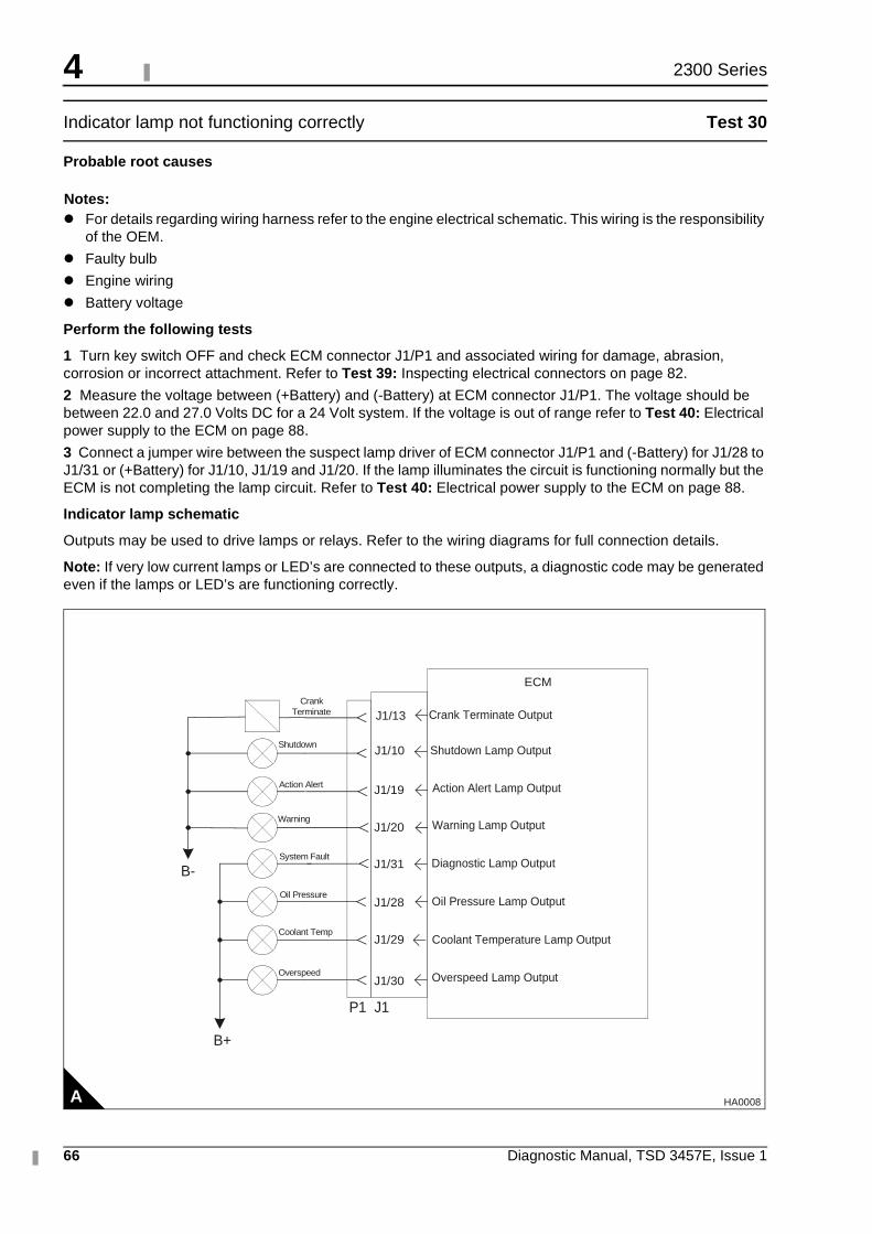
4
66 Diagnostic Manual, TSD 3457E, Issue 1
2300 Series
Indicator lamp not functioning correctly Test 30
Probable root causes
Notes:� For details regarding wiring harness refer to the engine electrical schematic. This wiring is the responsibility
of the OEM.
� Faulty bulb
� Engine wiring
� Battery voltage
Perform the following tests
1 Turn key switch OFF and check ECM connector J1/P1 and associated wiring for damage, abrasion, corrosion or incorrect attachment. Refer to Test 39: Inspecting electrical connectors on page 82.
2 Measure the voltage between (+Battery) and (-Battery) at ECM connector J1/P1. The voltage should be between 22.0 and 27.0 Volts DC for a 24 Volt system. If the voltage is out of range refer to Test 40: Electrical power supply to the ECM on page 88.
3 Connect a jumper wire between the suspect lamp driver of ECM connector J1/P1 and (-Battery) for J1/28 to J1/31 or (+Battery) for J1/10, J1/19 and J1/20. If the lamp illuminates the circuit is functioning normally but the ECM is not completing the lamp circuit. Refer to Test 40: Electrical power supply to the ECM on page 88.
Indicator lamp schematic
Outputs may be used to drive lamps or relays. Refer to the wiring diagrams for full connection details.
Note: If very low current lamps or LED’s are connected to these outputs, a diagnostic code may be generated even if the lamps or LED’s are functioning correctly.
A
ECM
J1/10
J1/19
J1/20
J1/31
P1 J1
Shutdown Lamp Output
Action Alert Lamp Output
Warning Lamp Output
Diagnostic Lamp Output
J1/28 Oil Pressure Lamp Output
J1/29 Coolant Temperature Lamp Output
J1/30 Overspeed Lamp Output
B-
B+
Shutdown
Action Alert
Warning
System Fault
Oil Pressure
Coolant Temp
Overspeed
Crank Terminate J1/13 Crank Terminate Output
HA0008
4
Diagnostic Manual, TSD 3457E, Issue 1 67
2300 Series
Inlet air manifold temperature is too high Test 31
Note: This is NOT an electronic system problem. Refer to the Workshop Manual for additional information on the following tests.
Probable root causes
� High Inlet Air Temperature Warning (event code) 368-01
The engine is running, the inlet air manifold temperature sensor reading is greater than the preset level for two seconds. Diagnostic codes 262-03 +5 V Supply Above Normal or 262-04 +5 V Supply Below Normal are not active. The event code and diagnostic code will be logged.
� High Inlet Air Temperature Action Alert (event code) 368-02
The engine is running, the inlet air manifold temperature sensor reading is greater than or equal to the preset level for at least two seconds. Diagnostic codes 262-03 +5 V Supply Above Normal or 262-04 +5 V Supply Below Normal are not active. The event code and diagnostic code will be logged.
� Incorrect fuel injection timing calibration
� Low air inlet system pressure
� Air inlet system has a restriction
Perform the following tests
1 Connect an electronic service tool and check for engine speed/timing error. Test 47: Engine speed/timing calibration on page 134.
2 Check pressure in the air inlet manifold. Check for air inlet leaks. Look for restrictions at the air cleaner. Check for leaks between inlet manifold and turbocharger. Repair or renew as necessary.
3 Check for air inlet restrictions. Refer to the Workshop Manual. Repair as necessary.
4
68 Diagnostic Manual, TSD 3457E, Issue 1
2300 Series
Engine has a high fuel temperature Test 32
Note: This is NOT an electronic system problem. Refer to the Workshop Manual for additional information on the following tests.
Probable root causes
� High Fuel Temp Warning (event code) 363-01
The engine speed is greater than 1000 rev/min, the fuel temperature sensor reading is greater than 60 °C (140 °F) for 30 seconds. Diagnostic codes 262-03 +5V Supply Above Normal or 262-04 +5V Supply Below Normal are not active. The event code and diagnostic code will be logged and the warning lamp is illuminated.
� Incorrect sensor installation
� Low fuel level
� Poor fuel quality
� Low supply pressure
� Insufficient size of fuel tank
� A fuel cooler may be required
Perform the following tests
1 Check that the fuel temperature sensor has been correctly installed. Refer to the Workshop Manual.
2 Refer to Test 29: Engine has a fuel supply problem on page 65.
4
Diagnostic Manual, TSD 3457E, Issue 1 69
2300 Series
Diagnostic procedures with an event code
General information
This section is to be used for diagnosing problems that have event codes but do not have ACTIVE diagnostic codes.
Event codes
Event codes indicate an actual engine fault, e.g. low oil pressure, rather than an electronic component failure.
There are three possible levels of severity of the fault.
Level 1 - Operator Warning
To warn the operator or machine control system of a possible condition that requires operator attention.
Level 2 - Action (Derate or Alert)
To inform the operator or machine control system to take action to enable the correct control of the system. In most cases the OEM will use this level for a controlled shutdown of the engine in order to protect it from damage.
Note: There are no derates set on the 2806/2306 engines. The TIPSS/EST Service Tool incorrectly shows Action Alerts as Derates on certain screens.
Level 3 - Shutdown
At this level the ECM will immediately stop the engine unless critical override is enabled and signal that a critical fault level has been reached.
Caution: If critical override is enabled the product is now operating in a condition outside its scope of supply and may cause injury or be damaged in such a way as to invalidate the warranty.
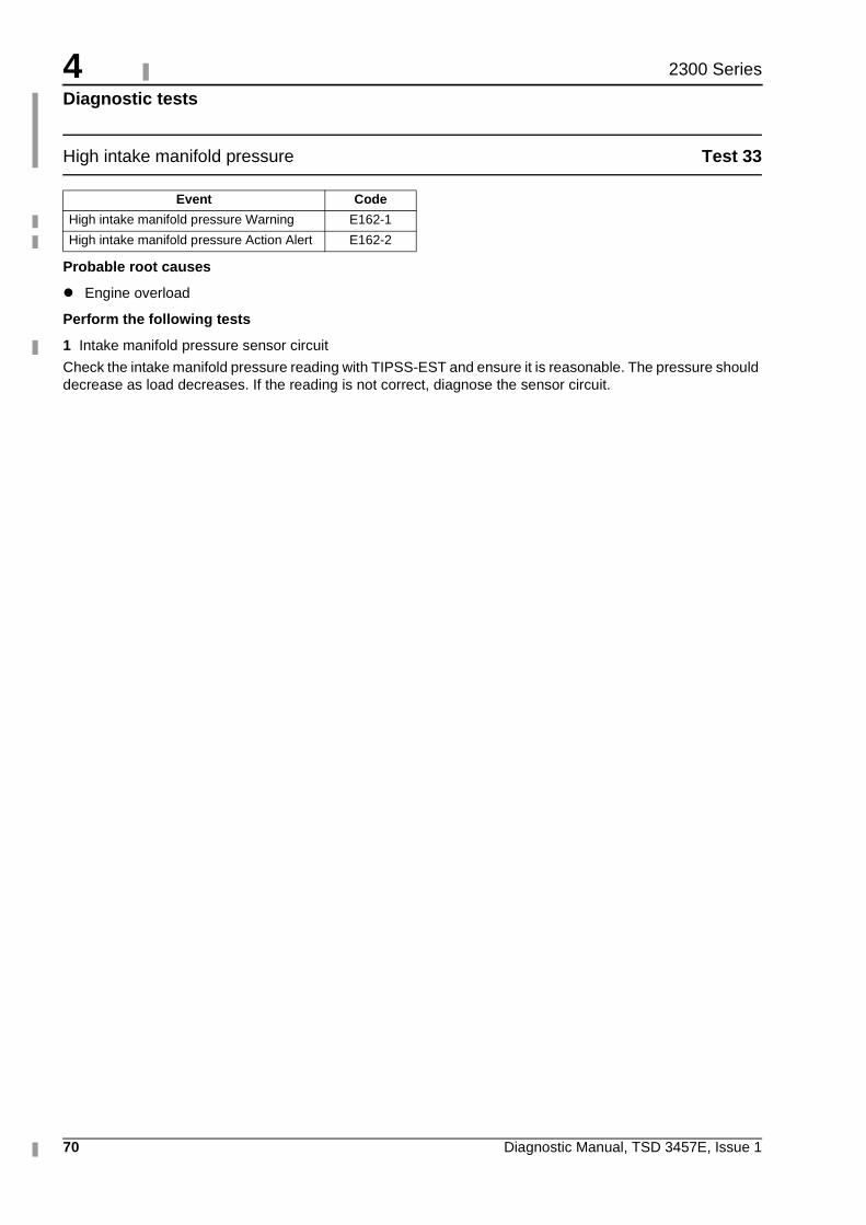
4
70 Diagnostic Manual, TSD 3457E, Issue 1
2300 Series
Diagnostic tests
High intake manifold pressure Test 33
Probable root causes
� Engine overload
Perform the following tests
1 Intake manifold pressure sensor circuit
Check the intake manifold pressure reading with TIPSS-EST and ensure it is reasonable. The pressure should decrease as load decreases. If the reading is not correct, diagnose the sensor circuit.
Event Code
High intake manifold pressure Warning E162-1
High intake manifold pressure Action Alert E162-2
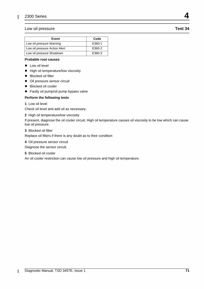
4
Diagnostic Manual, TSD 3457E, Issue 1 71
2300 Series
Low oil pressure Test 34
Probable root causes
� Low oil level
� High oil temperature/low viscosity
� Blocked oil filter
� Oil pressure sensor circuit
� Blocked oil cooler
� Faulty oil pump/oil pump bypass valve
Perform the following tests
1 Low oil level
Check oil level and add oil as necessary.
2 High oil temperature/low viscosity
If present, diagnose the oil cooler circuit. High oil temperature causes oil viscosity to be low which can cause low oil pressure.
3 Blocked oil filter
Replace oil filters if there is any doubt as to their condition
4 Oil pressure sensor circuit
Diagnose the sensor circuit.
5 Blocked oil cooler
An oil cooler restriction can cause low oil pressure and high oil temperature.
Event Code
Low oil pressure Warning E360-1
Low oil pressure Action Alert E360-2
Low oil pressure Shutdown E360-3
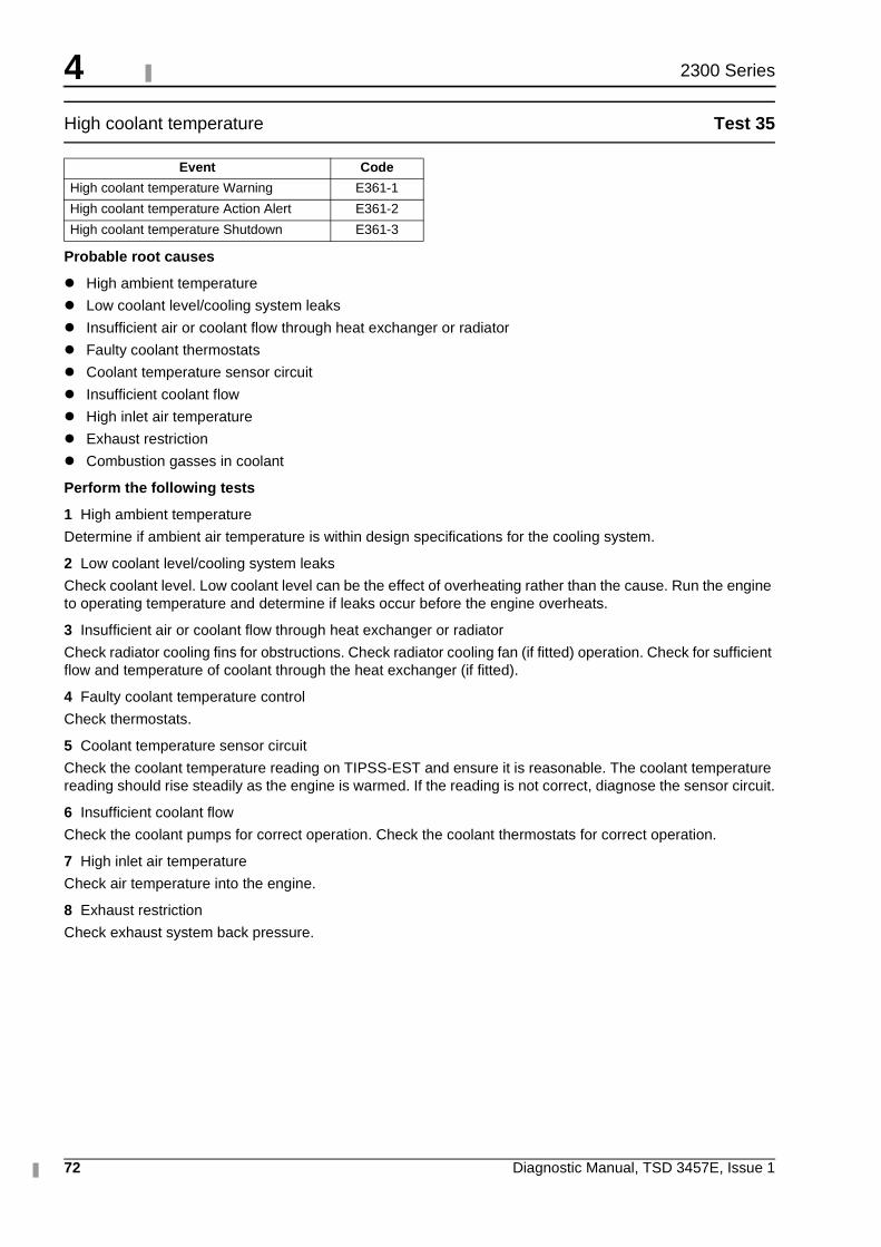
4
72 Diagnostic Manual, TSD 3457E, Issue 1
2300 Series
High coolant temperature Test 35
Probable root causes
� High ambient temperature
� Low coolant level/cooling system leaks
� Insufficient air or coolant flow through heat exchanger or radiator
� Faulty coolant thermostats
� Coolant temperature sensor circuit
� Insufficient coolant flow
� High inlet air temperature
� Exhaust restriction
� Combustion gasses in coolant
Perform the following tests
1 High ambient temperature
Determine if ambient air temperature is within design specifications for the cooling system.
2 Low coolant level/cooling system leaks
Check coolant level. Low coolant level can be the effect of overheating rather than the cause. Run the engine to operating temperature and determine if leaks occur before the engine overheats.
3 Insufficient air or coolant flow through heat exchanger or radiator
Check radiator cooling fins for obstructions. Check radiator cooling fan (if fitted) operation. Check for sufficient flow and temperature of coolant through the heat exchanger (if fitted).
4 Faulty coolant temperature control
Check thermostats.
5 Coolant temperature sensor circuit
Check the coolant temperature reading on TIPSS-EST and ensure it is reasonable. The coolant temperature reading should rise steadily as the engine is warmed. If the reading is not correct, diagnose the sensor circuit.
6 Insufficient coolant flow
Check the coolant pumps for correct operation. Check the coolant thermostats for correct operation.
7 High inlet air temperature
Check air temperature into the engine.
8 Exhaust restriction
Check exhaust system back pressure.
Event Code
High coolant temperature Warning E361-1
High coolant temperature Action Alert E361-2
High coolant temperature Shutdown E361-3
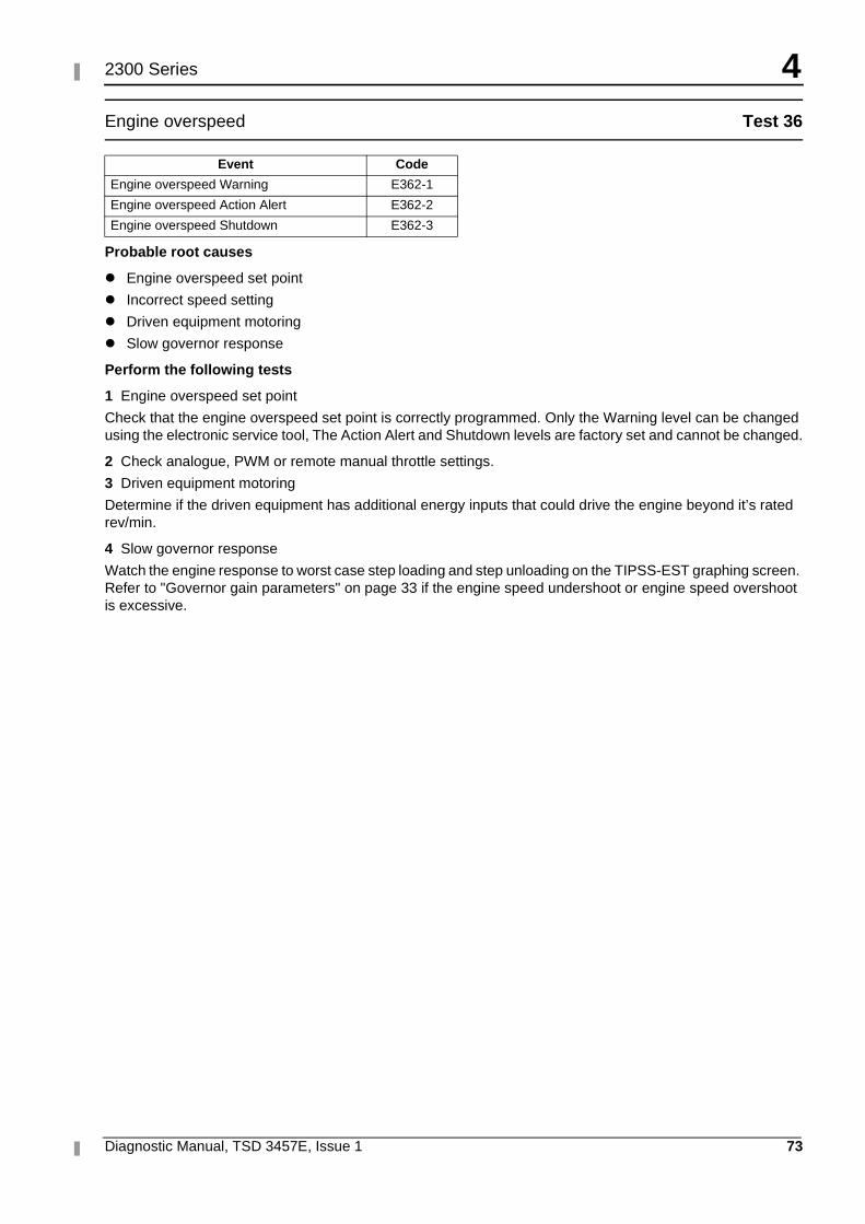
4
Diagnostic Manual, TSD 3457E, Issue 1 73
2300 Series
Engine overspeed Test 36
Probable root causes
� Engine overspeed set point
� Incorrect speed setting
� Driven equipment motoring
� Slow governor response
Perform the following tests
1 Engine overspeed set point
Check that the engine overspeed set point is correctly programmed. Only the Warning level can be changed using the electronic service tool, The Action Alert and Shutdown levels are factory set and cannot be changed.
2 Check analogue, PWM or remote manual throttle settings.
3 Driven equipment motoring
Determine if the driven equipment has additional energy inputs that could drive the engine beyond it’s rated rev/min.
4 Slow governor response
Watch the engine response to worst case step loading and step unloading on the TIPSS-EST graphing screen. Refer to "Governor gain parameters" on page 33 if the engine speed undershoot or engine speed overshoot is excessive.
Event Code
Engine overspeed Warning E362-1
Engine overspeed Action Alert E362-2
Engine overspeed Shutdown E362-3
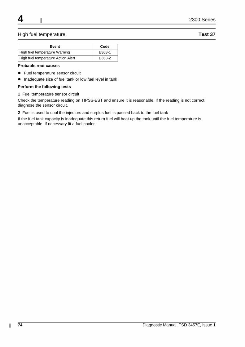
4
74 Diagnostic Manual, TSD 3457E, Issue 1
2300 Series
High fuel temperature Test 37
Probable root causes
� Fuel temperature sensor circuit
� Inadequate size of fuel tank or low fuel level in tank
Perform the following tests
1 Fuel temperature sensor circuit
Check the temperature reading on TIPSS-EST and ensure it is reasonable. If the reading is not correct, diagnose the sensor circuit.
2 Fuel is used to cool the injectors and surplus fuel is passed back to the fuel tank
If the fuel tank capacity is inadequate this return fuel will heat up the tank until the fuel temperature is unacceptable. If necessary fit a fuel cooler.
Event Code
High fuel temperature Warning E363-1
High fuel temperature Action Alert E363-2
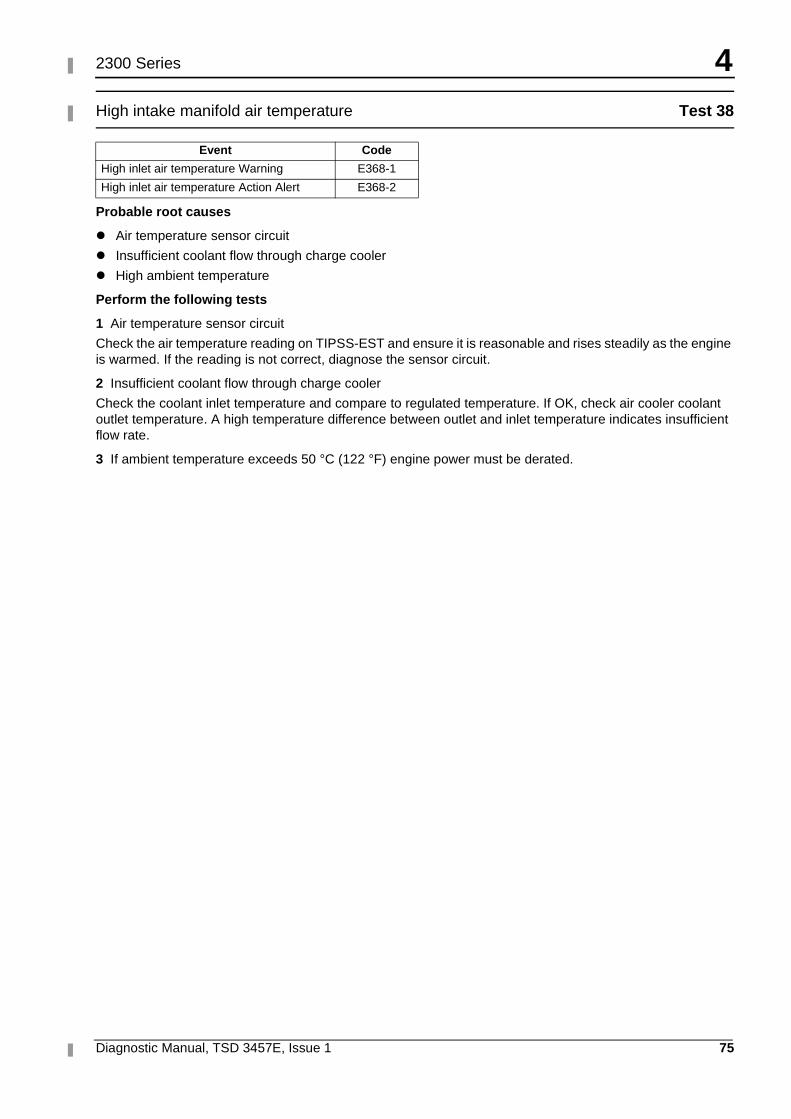
4
Diagnostic Manual, TSD 3457E, Issue 1 75
2300 Series
High intake manifold air temperature Test 38
Probable root causes
� Air temperature sensor circuit
� Insufficient coolant flow through charge cooler
� High ambient temperature
Perform the following tests
1 Air temperature sensor circuit
Check the air temperature reading on TIPSS-EST and ensure it is reasonable and rises steadily as the engine is warmed. If the reading is not correct, diagnose the sensor circuit.
2 Insufficient coolant flow through charge cooler
Check the coolant inlet temperature and compare to regulated temperature. If OK, check air cooler coolant outlet temperature. A high temperature difference between outlet and inlet temperature indicates insufficient flow rate.
3 If ambient temperature exceeds 50 °C (122 °F) engine power must be derated.
Event Code
High inlet air temperature Warning E368-1
High inlet air temperature Action Alert E368-2
4
76 Diagnostic Manual, TSD 3457E, Issue 1
2300 Series
Diagnostic procedures with a diagnostic fault code
General information
Some of the wiring detailed in this section may be supplied by the OEM and may differ from the diagrams in this manual.
Refer to the OEM supplied wiring diagrams where appropriate.
Diagnostic codes
Diagnostic codes alert the operator that a problem exists and indicate the nature of the problem to the service technician. Diagnostic codes may be viewed using an electronic service tool (TIPSS-EST).
Diagnostic codes consist of three parts, MID, CID and FMI
� The MID or Module IDentifier indicates which electronic module generated the diagnostic code. The ECM is MID=24.
� The CID, or Component IDentifier, indicates which component in the system the diagnostic code is for.
� The FMI, or Failure Mode Identifier indicates what the failure mode is. Refer to "Diagnostic terminology" on page 78 for additional details.
Note: Do not confuse diagnostic codes with diagnostic events. Events can be logged in the ECM to track information about the engine. An example would be a low oil pressure event. An event is generated when the engine oil pressure is low but not out of range for the sensor. This does not indicate a problem with the sensor, rather it indicates a problem with the engine oil pressure. Refer to "Diagnostic procedures with an event code" on page 69 for more information.
Active diagnostic codes
An active diagnostic code represents a problem with the electronic control system that should be investigated and corrected as soon as possible.
When an active diagnostic code is generated, the diagnostic warning indicator is activated to alert the operator. If the condition generating the diagnostic occurs only for a brief moment, the message will disappear and the diagnostic code will be Logged in the ECM memory.
Logged diagnostic codes
When the ECM generates a diagnostic code, it usually logs the code in permanent memory within the ECM. The ECM has an internal diagnostic clock and will record the hour of the first occurrence, the hour of the last occurrence and the number of occurrences of the code.
Knowing when and how often the code was generated can be a valuable indicator when diagnosing intermittent problems.
An electronic service tool can retrieve and delete Logged codes. Any Logged diagnostic codes will automatically be deleted if no additional occurrences are recorded in 100 hours.
When investigating logged diagnostic codes, keep in mind the following information.
� Some diagnostic codes may be easily triggered and do not result in operator complaints. If the time the code was logged does not relate to a complaint, there may be nothing to fix.
� The most likely cause of an intermittent problem is a faulty connection or damaged wiring. Next likely is a component failure (sensor or switch). Least likely is failure of the ECM itself.
� Diagnostic codes that are logged repeatedly may indicate a problem that needs special investigation.
Continued
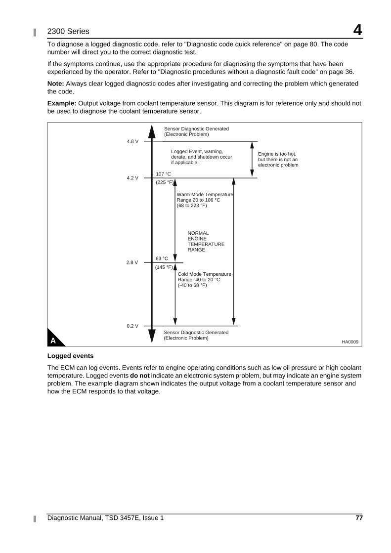
4
Diagnostic Manual, TSD 3457E, Issue 1 77
2300 Series
To diagnose a logged diagnostic code, refer to "Diagnostic code quick reference" on page 80. The code number will direct you to the correct diagnostic test.
If the symptoms continue, use the appropriate procedure for diagnosing the symptoms that have been experienced by the operator. Refer to "Diagnostic procedures without a diagnostic fault code" on page 36.
Note: Always clear logged diagnostic codes after investigating and correcting the problem which generated the code.
Example: Output voltage from coolant temperature sensor. This diagram is for reference only and should not be used to diagnose the coolant temperature sensor.
Logged events
The ECM can log events. Events refer to engine operating conditions such as low oil pressure or high coolant temperature. Logged events do not indicate an electronic system problem, but may indicate an engine system problem. The example diagram shown indicates the output voltage from a coolant temperature sensor and how the ECM responds to that voltage.
A
4.8 V
4.2 V
2.8 V
107 °C
(225 °F)
63 °C
(145 °F)
Sensor Diagnostic Generated (Electronic Problem)
Cold Mode Temperature Range -40 to 20 °C (-40 to 68 °F)
NORMAL ENGINE TEMPERA TURE RANGE.
Engine is too hot, but there is not an electronic problem
Warm Mode Temperature Range 20 to 106 °C (68 to 223 °F)
Logged Event, warning, derate, and shutdown occur if applicable.
Sensor Diagnostic Generated (Electronic Problem)
0.2 V
HA0009
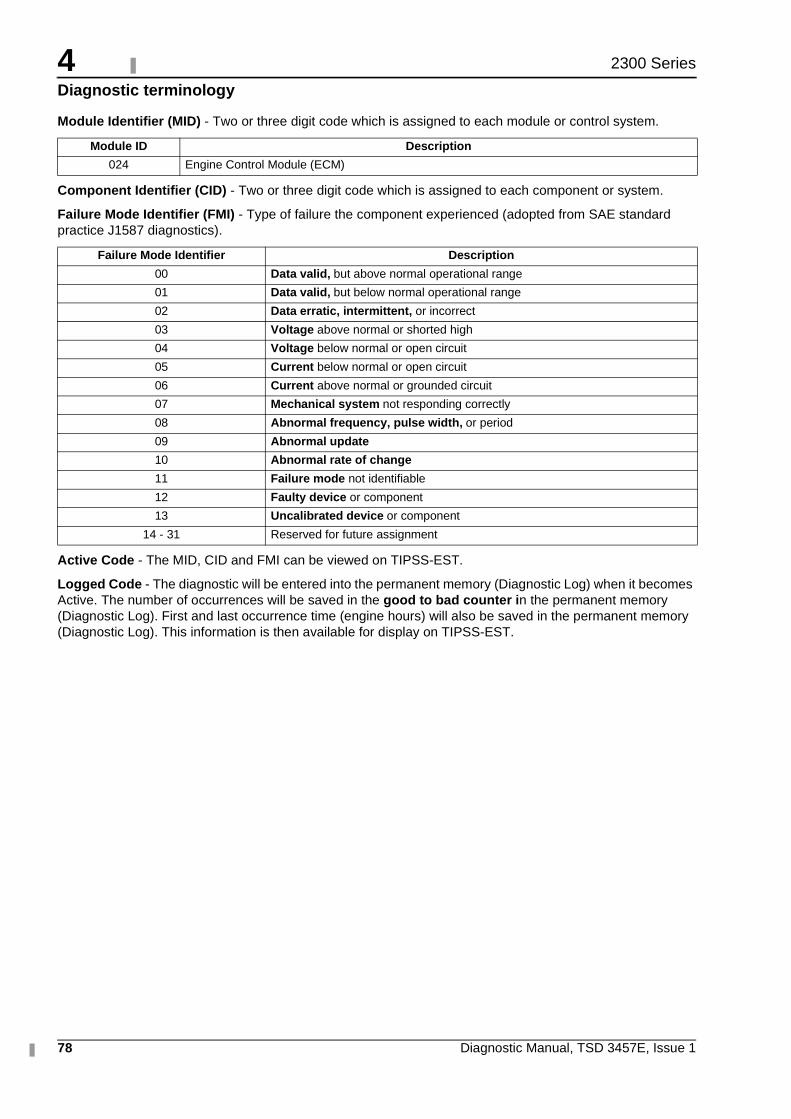
4
78 Diagnostic Manual, TSD 3457E, Issue 1
2300 Series
Diagnostic terminology
Module Identifier (MID) - Two or three digit code which is assigned to each module or control system.
Component Identifier (CID) - Two or three digit code which is assigned to each component or system.
Failure Mode Identifier (FMI) - Type of failure the component experienced (adopted from SAE standard practice J1587 diagnostics).
Active Code - The MID, CID and FMI can be viewed on TIPSS-EST.
Logged Code - The diagnostic will be entered into the permanent memory (Diagnostic Log) when it becomes Active. The number of occurrences will be saved in the good to bad counter in the permanent memory (Diagnostic Log). First and last occurrence time (engine hours) will also be saved in the permanent memory (Diagnostic Log). This information is then available for display on TIPSS-EST.
Module ID Description
024 Engine Control Module (ECM)
Failure Mode Identifier Description
00 Data valid, but above normal operational range
01 Data valid, but below normal operational range
02 Data erratic, intermittent, or incorrect
03 Voltage above normal or shorted high
04 Voltage below normal or open circuit
05 Current below normal or open circuit
06 Current above normal or grounded circuit
07 Mechanical system not responding correctly
08 Abnormal frequency, pulse width, or period
09 Abnormal update
10 Abnormal rate of change
11 Failure mode not identifiable
12 Faulty device or component
13 Uncalibrated device or component
14 - 31 Reserved for future assignment
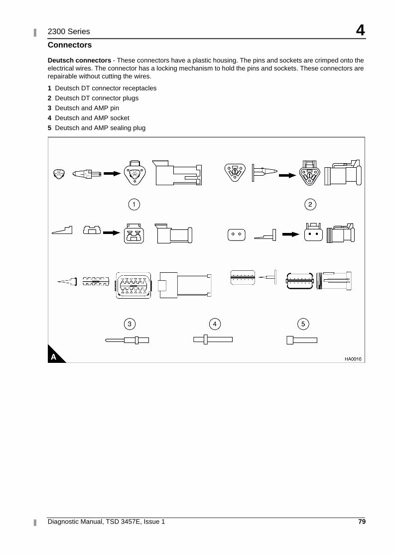
4
Diagnostic Manual, TSD 3457E, Issue 1 79
2300 Series
Connectors
Deutsch connectors - These connectors have a plastic housing. The pins and sockets are crimped onto the electrical wires. The connector has a locking mechanism to hold the pins and sockets. These connectors are repairable without cutting the wires.
1 Deutsch DT connector receptacles
2 Deutsch DT connector plugs
3 Deutsch and AMP pin
4 Deutsch and AMP socket
5 Deutsch and AMP sealing plug
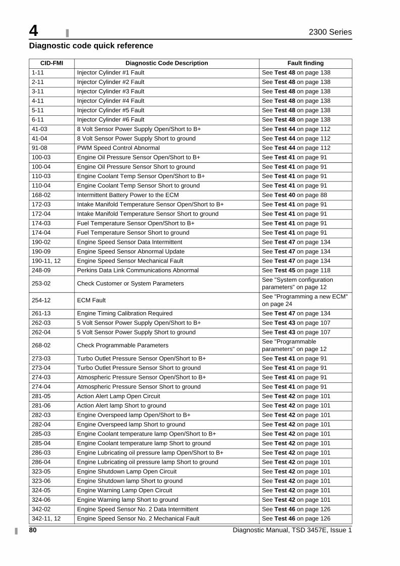
4
80 Diagnostic Manual, TSD 3457E, Issue 1
2300 Series
Diagnostic code quick reference
CID-FMI Diagnostic Code Description Fault finding
1-11 Injector Cylinder #1 Fault See Test 48 on page 138
2-11 Injector Cylinder #2 Fault See Test 48 on page 138
3-11 Injector Cylinder #3 Fault See Test 48 on page 138
4-11 Injector Cylinder #4 Fault See Test 48 on page 138
5-11 Injector Cylinder #5 Fault See Test 48 on page 138
6-11 Injector Cylinder #6 Fault See Test 48 on page 138
41-03 8 Volt Sensor Power Supply Open/Short to B+ See Test 44 on page 112
41-04 8 Volt Sensor Power Supply Short to ground See Test 44 on page 112
91-08 PWM Speed Control Abnormal See Test 44 on page 112
100-03 Engine Oil Pressure Sensor Open/Short to B+ See Test 41 on page 91
100-04 Engine Oil Pressure Sensor Short to ground See Test 41 on page 91
110-03 Engine Coolant Temp Sensor Open/Short to B+ See Test 41 on page 91
110-04 Engine Coolant Temp Sensor Short to ground See Test 41 on page 91
168-02 Intermittent Battery Power to the ECM See Test 40 on page 88
172-03 Intake Manifold Temperature Sensor Open/Short to B+ See Test 41 on page 91
172-04 Intake Manifold Temperature Sensor Short to ground See Test 41 on page 91
174-03 Fuel Temperature Sensor Open/Short to B+ See Test 41 on page 91
174-04 Fuel Temperature Sensor Short to ground See Test 41 on page 91
190-02 Engine Speed Sensor Data Intermittent See Test 47 on page 134
190-09 Engine Speed Sensor Abnormal Update See Test 47 on page 134
190-11, 12 Engine Speed Sensor Mechanical Fault See Test 47 on page 134
248-09 Perkins Data Link Communications Abnormal See Test 45 on page 118
253-02 Check Customer or System Parameters See "System configuration parameters" on page 12
254-12 ECM FaultSee "Programming a new ECM" on page 24
261-13 Engine Timing Calibration Required See Test 47 on page 134
262-03 5 Volt Sensor Power Supply Open/Short to B+ See Test 43 on page 107
262-04 5 Volt Sensor Power Supply Short to ground See Test 43 on page 107
268-02 Check Programmable ParametersSee "Programmable parameters" on page 12
273-03 Turbo Outlet Pressure Sensor Open/Short to B+ See Test 41 on page 91
273-04 Turbo Outlet Pressure Sensor Short to ground See Test 41 on page 91
274-03 Atmospheric Pressure Sensor Open/Short to B+ See Test 41 on page 91
274-04 Atmospheric Pressure Sensor Short to ground See Test 41 on page 91
281-05 Action Alert Lamp Open Circuit See Test 42 on page 101
281-06 Action Alert lamp Short to ground See Test 42 on page 101
282-03 Engine Overspeed lamp Open/Short to B+ See Test 42 on page 101
282-04 Engine Overspeed lamp Short to ground See Test 42 on page 101
285-03 Engine Coolant temperature lamp Open/Short to B+ See Test 42 on page 101
285-04 Engine Coolant temperature lamp Short to ground See Test 42 on page 101
286-03 Engine Lubricating oil pressure lamp Open/Short to B+ See Test 42 on page 101
286-04 Engine Lubricating oil pressure lamp Short to ground See Test 42 on page 101
323-05 Engine Shutdown Lamp Open Circuit See Test 42 on page 101
323-06 Engine Shutdown lamp Short to ground See Test 42 on page 101
324-05 Engine Warning Lamp Open Circuit See Test 42 on page 101
324-06 Engine Warning lamp Short to ground See Test 42 on page 101
342-02 Engine Speed Sensor No. 2 Data Intermittent See Test 46 on page 126
342-11, 12 Engine Speed Sensor No. 2 Mechanical Fault See Test 46 on page 126
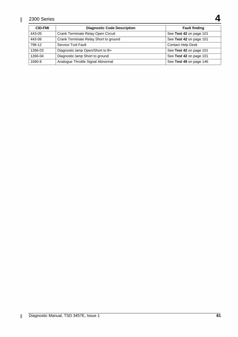
4
Diagnostic Manual, TSD 3457E, Issue 1 81
2300 Series
443-05 Crank Terminate Relay Open Circuit See Test 42 on page 101
443-06 Crank Terminate Relay Short to ground See Test 42 on page 101
799-12 Service Tool Fault Contact Help Desk
1266-03 Diagnostic lamp Open/Short to B+ See Test 42 on page 101
1266-04 Diagnostic lamp Short to ground See Test 42 on page 101
1690-8 Analogue Throttle Signal Abnormal See Test 49 on page 146
CID-FMI Diagnostic Code Description Fault finding
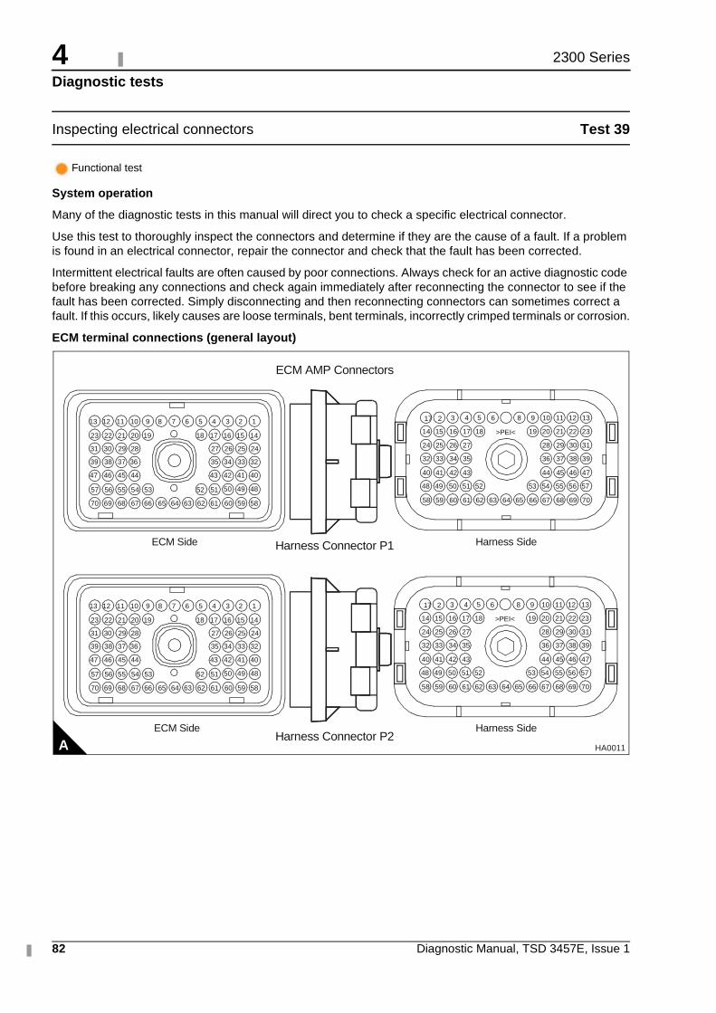
4
82 Diagnostic Manual, TSD 3457E, Issue 1
2300 Series
Diagnostic tests
Inspecting electrical connectors Test 39
System operation
Many of the diagnostic tests in this manual will direct you to check a specific electrical connector.
Use this test to thoroughly inspect the connectors and determine if they are the cause of a fault. If a problem is found in an electrical connector, repair the connector and check that the fault has been corrected.
Intermittent electrical faults are often caused by poor connections. Always check for an active diagnostic code before breaking any connections and check again immediately after reconnecting the connector to see if the fault has been corrected. Simply disconnecting and then reconnecting connectors can sometimes correct a fault. If this occurs, likely causes are loose terminals, bent terminals, incorrectly crimped terminals or corrosion.
ECM terminal connections (general layout)
Functional test
AECM Side
Harness Connector P1 Harness SideECM Side
Harness Connector P2
ECM AMP Connectors
5859606162636566676870
13
64
51525354555657
43
32333435
24252627
44454647
36373839
28293031
14151617181920212223
123456789101112
69
42 41 40
50 49 48
>PEI< 232221201918171614 15
13121110986543217
31302928272624 25
39383736353432 33
47464544434240 41
575655545352515048 49
706968676662616058 59 656463
Harness Side
HA0011
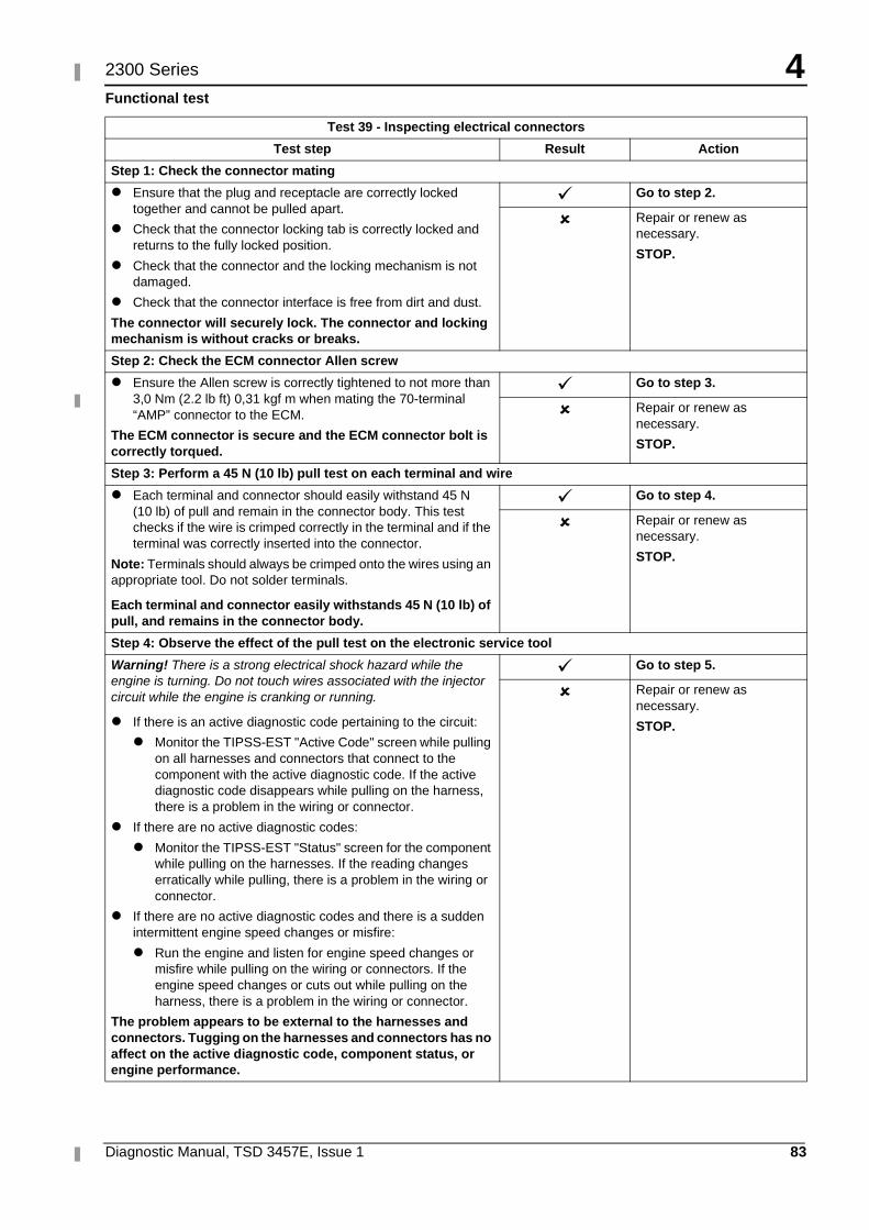
4
Diagnostic Manual, TSD 3457E, Issue 1 83
2300 Series
Functional test
Test 39 - Inspecting electrical connectors
Test step Result Action
Step 1: Check the connector mating
� Ensure that the plug and receptacle are correctly locked together and cannot be pulled apart.
� Check that the connector locking tab is correctly locked and returns to the fully locked position.
� Check that the connector and the locking mechanism is not damaged.
� Check that the connector interface is free from dirt and dust.
The connector will securely lock. The connector and locking mechanism is without cracks or breaks.
� Go to step 2.
� Repair or renew as necessary.
STOP.
Step 2: Check the ECM connector Allen screw
� Ensure the Allen screw is correctly tightened to not more than 3,0 Nm (2.2 lb ft) 0,31 kgf m when mating the 70-terminal “AMP” connector to the ECM.
The ECM connector is secure and the ECM connector bolt is correctly torqued.
� Go to step 3.
� Repair or renew as necessary.
STOP.
Step 3: Perform a 45 N (10 lb) pull test on each terminal and wire
� Each terminal and connector should easily withstand 45 N (10 lb) of pull and remain in the connector body. This test checks if the wire is crimped correctly in the terminal and if the terminal was correctly inserted into the connector.
Note: Terminals should always be crimped onto the wires using an appropriate tool. Do not solder terminals.
Each terminal and connector easily withstands 45 N (10 lb) of pull, and remains in the connector body.
� Go to step 4.
� Repair or renew as necessary.
STOP.
Step 4: Observe the effect of the pull test on the electronic service tool
Warning! There is a strong electrical shock hazard while the engine is turning. Do not touch wires associated with the injector circuit while the engine is cranking or running.
� If there is an active diagnostic code pertaining to the circuit:
� Monitor the TIPSS-EST "Active Code" screen while pulling on all harnesses and connectors that connect to the component with the active diagnostic code. If the active diagnostic code disappears while pulling on the harness, there is a problem in the wiring or connector.
� If there are no active diagnostic codes:
� Monitor the TIPSS-EST "Status" screen for the component while pulling on the harnesses. If the reading changes erratically while pulling, there is a problem in the wiring or connector.
� If there are no active diagnostic codes and there is a sudden intermittent engine speed changes or misfire:
� Run the engine and listen for engine speed changes or misfire while pulling on the wiring or connectors. If the engine speed changes or cuts out while pulling on the harness, there is a problem in the wiring or connector.
The problem appears to be external to the harnesses and connectors. Tugging on the harnesses and connectors has no affect on the active diagnostic code, component status, or engine performance.
� Go to step 5.
� Repair or renew as necessary.
STOP.
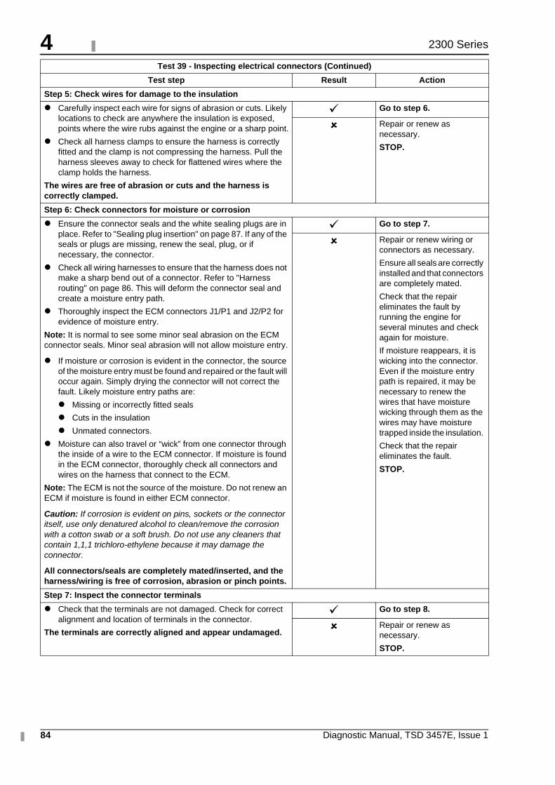
4
84 Diagnostic Manual, TSD 3457E, Issue 1
2300 Series
Step 5: Check wires for damage to the insulation
� Carefully inspect each wire for signs of abrasion or cuts. Likely locations to check are anywhere the insulation is exposed, points where the wire rubs against the engine or a sharp point.
� Check all harness clamps to ensure the harness is correctly fitted and the clamp is not compressing the harness. Pull the harness sleeves away to check for flattened wires where the clamp holds the harness.
The wires are free of abrasion or cuts and the harness is correctly clamped.
� Go to step 6.
� Repair or renew as necessary.
STOP.
Step 6: Check connectors for moisture or corrosion
� Ensure the connector seals and the white sealing plugs are in place. Refer to "Sealing plug insertion" on page 87. If any of the seals or plugs are missing, renew the seal, plug, or if necessary, the connector.
� Check all wiring harnesses to ensure that the harness does not make a sharp bend out of a connector. Refer to "Harness routing" on page 86. This will deform the connector seal and create a moisture entry path.
� Thoroughly inspect the ECM connectors J1/P1 and J2/P2 for evidence of moisture entry.
Note: It is normal to see some minor seal abrasion on the ECM connector seals. Minor seal abrasion will not allow moisture entry.
� If moisture or corrosion is evident in the connector, the source of the moisture entry must be found and repaired or the fault will occur again. Simply drying the connector will not correct the fault. Likely moisture entry paths are:
� Missing or incorrectly fitted seals
� Cuts in the insulation
� Unmated connectors.
� Moisture can also travel or “wick” from one connector through the inside of a wire to the ECM connector. If moisture is found in the ECM connector, thoroughly check all connectors and wires on the harness that connect to the ECM.
Note: The ECM is not the source of the moisture. Do not renew an ECM if moisture is found in either ECM connector.
Caution: If corrosion is evident on pins, sockets or the connector itself, use only denatured alcohol to clean/remove the corrosion with a cotton swab or a soft brush. Do not use any cleaners that contain 1,1,1 trichloro-ethylene because it may damage the connector.
All connectors/seals are completely mated/inserted, and the harness/wiring is free of corrosion, abrasion or pinch points.
� Go to step 7.
� Repair or renew wiring or connectors as necessary.
Ensure all seals are correctly installed and that connectors are completely mated.
Check that the repair eliminates the fault by running the engine for several minutes and check again for moisture.
If moisture reappears, it is wicking into the connector. Even if the moisture entry path is repaired, it may be necessary to renew the wires that have moisture wicking through them as the wires may have moisture trapped inside the insulation.
Check that the repair eliminates the fault.
STOP.
Step 7: Inspect the connector terminals
� Check that the terminals are not damaged. Check for correct alignment and location of terminals in the connector.
The terminals are correctly aligned and appear undamaged.
� Go to step 8.
� Repair or renew as necessary.
STOP.
Test 39 - Inspecting electrical connectors (Continued)
Test step Result Action
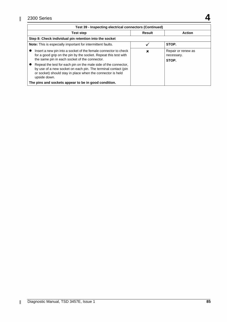
4
Diagnostic Manual, TSD 3457E, Issue 1 85
2300 Series
Step 8: Check individual pin retention into the socket
Note: This is especially important for intermittent faults.
� Insert a new pin into a socket of the female connector to check for a good grip on the pin by the socket. Repeat this test with the same pin in each socket of the connector.
� Repeat the test for each pin on the male side of the connector, by use of a new socket on each pin. The terminal contact (pin or socket) should stay in place when the connector is held upside down.
The pins and sockets appear to be in good condition.
� STOP.
� Repair or renew as necessary.
STOP.
Test 39 - Inspecting electrical connectors (Continued)
Test step Result Action
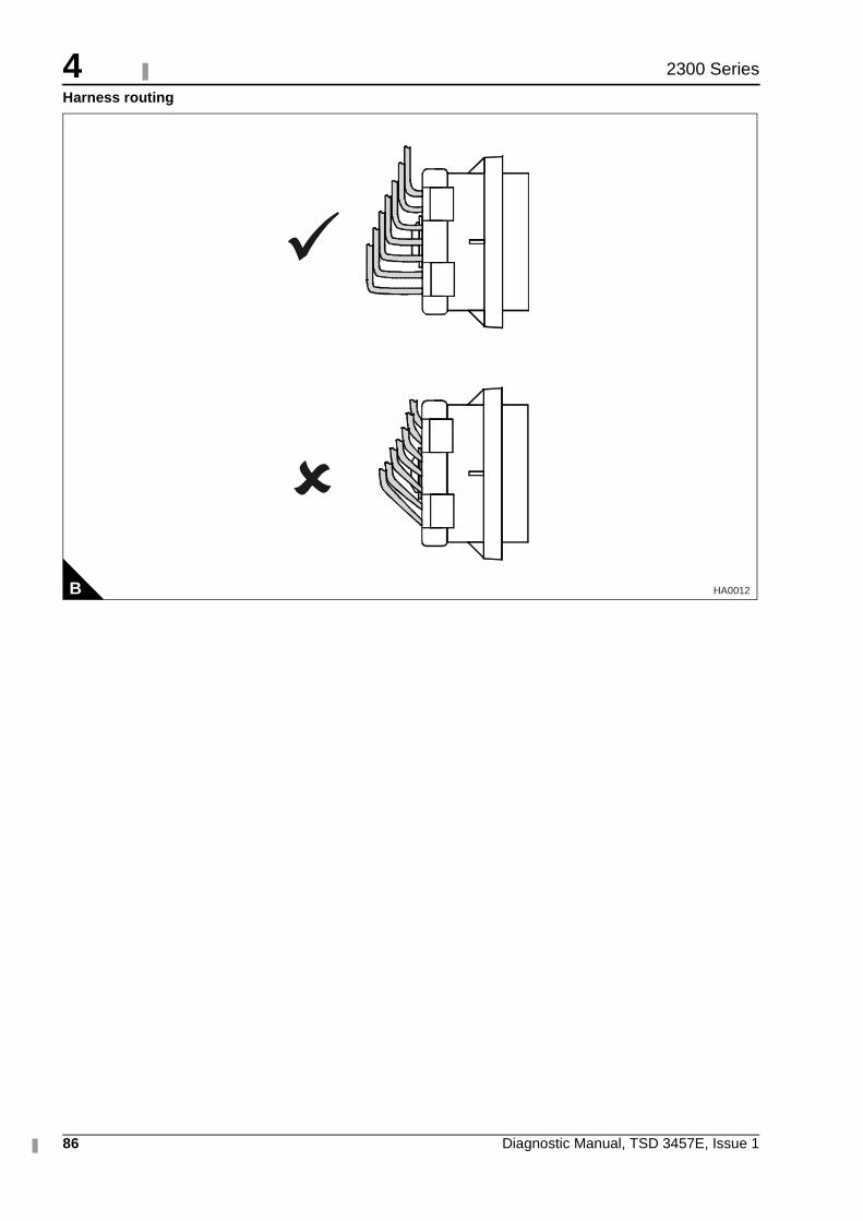
4
86 Diagnostic Manual, TSD 3457E, Issue 1
2300 Series
Harness routing
B HA0012
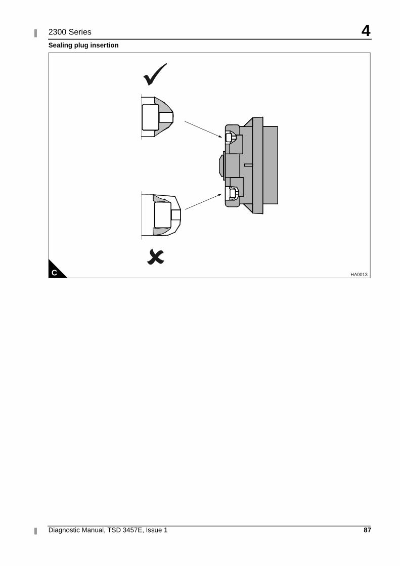
4
Diagnostic Manual, TSD 3457E, Issue 1 87
2300 Series
Sealing plug insertion
C HA0013
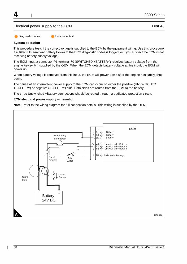
4
88 Diagnostic Manual, TSD 3457E, Issue 1
2300 Series
Electrical power supply to the ECM Test 40
System operation
This procedure tests if the correct voltage is supplied to the ECM by the equipment wiring. Use this procedure if a 168-02 Intermittent Battery Power to the ECM diagnostic codes is logged, or if you suspect the ECM is not receiving battery supply voltage.
The ECM input at connector P1 terminal-70 (SWITCHED +BATTERY) receives battery voltage from the engine key switch supplied by the OEM. When the ECM detects battery voltage at this input, the ECM will power up.
When battery voltage is removed from this input, the ECM will power down after the engine has safely shut down.
The cause of an intermittent power supply to the ECM can occur on either the positive (UNSWITCHED +BATTERY) or negative (-BATTERY) side. Both sides are routed from the ECM to the battery.
The three Unswitched +Battery connections should be routed through a dedicated protection circuit.
ECM electrical power supply schematic
Note: Refer to the wiring diagram for full connection details. This wiring is supplied by the OEM.
Diagnostic codes Functional test
A
ECM61 - Battery
- Battery6365
5253
48 Unswitched + BatteryUnswitched + BatteryUnswitched + Battery
70 Switched + Battery
- Battery
J1
CircuitBreaker
StarterMotor
Battery24V DC
+-
StartButton
EmergencyStop Button
KeySwitch
HA0014
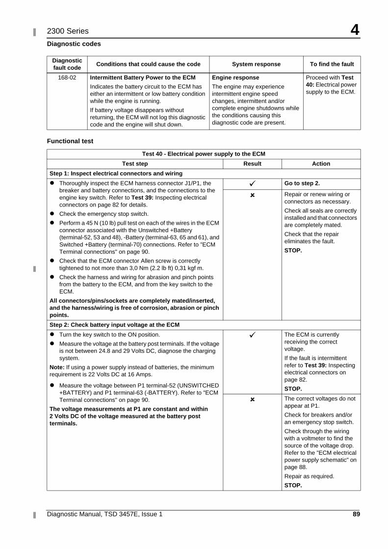
4
Diagnostic Manual, TSD 3457E, Issue 1 89
2300 Series
Diagnostic codes
Functional test
Diagnostic fault code
Conditions that could cause the code System response To find the fault
168-02 Intermittent Battery Power to the ECM
Indicates the battery circuit to the ECM has either an intermittent or low battery condition while the engine is running.
If battery voltage disappears without returning, the ECM will not log this diagnostic code and the engine will shut down.
Engine response
The engine may experience intermittent engine speed changes, intermittent and/or complete engine shutdowns while the conditions causing this diagnostic code are present.
Proceed with Test 40: Electrical power supply to the ECM.
Test 40 - Electrical power supply to the ECM
Test step Result Action
Step 1: Inspect electrical connectors and wiring
� Thoroughly inspect the ECM harness connector J1/P1, the breaker and battery connections, and the connections to the engine key switch. Refer to Test 39: Inspecting electrical connectors on page 82 for details.
� Check the emergency stop switch.
� Perform a 45 N (10 lb) pull test on each of the wires in the ECM connector associated with the Unswitched +Battery (terminal-52, 53 and 48), -Battery (terminal-63, 65 and 61), and Switched +Battery (terminal-70) connections. Refer to "ECM Terminal connections" on page 90.
� Check that the ECM connector Allen screw is correctly tightened to not more than 3,0 Nm (2.2 lb ft) 0,31 kgf m.
� Check the harness and wiring for abrasion and pinch points from the battery to the ECM, and from the key switch to the ECM.
All connectors/pins/sockets are completely mated/inserted, and the harness/wiring is free of corrosion, abrasion or pinch points.
� Go to step 2.
� Repair or renew wiring or connectors as necessary.
Check all seals are correctly installed and that connectors are completely mated.
Check that the repair eliminates the fault.
STOP.
Step 2: Check battery input voltage at the ECM
� Turn the key switch to the ON position.
� Measure the voltage at the battery post terminals. If the voltage is not between 24.8 and 29 Volts DC, diagnose the charging system.
Note: If using a power supply instead of batteries, the minimum requirement is 22 Volts DC at 16 Amps.
� Measure the voltage between P1 terminal-52 (UNSWITCHED +BATTERY) and P1 terminal-63 (-BATTERY). Refer to "ECM Terminal connections" on page 90.
The voltage measurements at P1 are constant and within 2 Volts DC of the voltage measured at the battery post terminals.
� The ECM is currently receiving the correct voltage.
If the fault is intermittent refer to Test 39: Inspecting electrical connectors on page 82.
STOP.
� The correct voltages do not appear at P1.
Check for breakers and/or an emergency stop switch.
Check through the wiring with a voltmeter to find the source of the voltage drop. Refer to the "ECM electrical power supply schematic" on page 88.
Repair as required.
STOP.
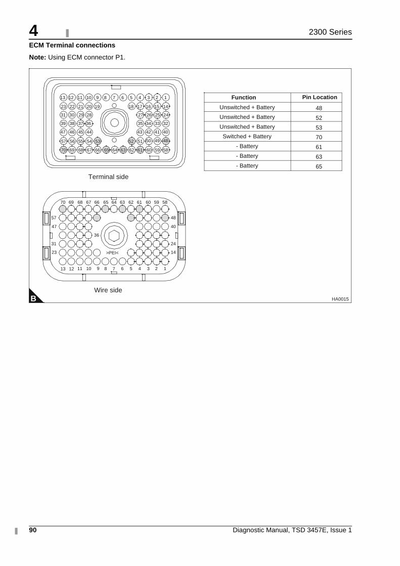
4
90 Diagnostic Manual, TSD 3457E, Issue 1
2300 Series
ECM Terminal connections
Note: Using ECM connector P1.
B
1234568910111213
14
24
40
48
23
31
47
57
36
>PEI<
5859606162636566676870
13
64
51525354555657
40414243
32333435
24252627
44454647
36373839
28293031
14151617181920212223
123456789101112
69
5859606162636566676870 6469
7
Terminal side
Wire side
484950
Unswitched + Battery
Unswitched + Battery
Unswitched + Battery
Switched + Battery
- Battery
- Battery
- Battery
48
52
53
70
61
63
65
Function Pin Location
HA0015
4
Diagnostic Manual, TSD 3457E, Issue 1 91
2300 Series
Analogue sensor open or short circuit test Test 41
System operation
Use this procedure to diagnose open or short circuit diagnostic codes for the oil pressure sensor, atmospheric pressure sensor, turbo outlet pressure sensor, fuel temperature sensor, engine coolant temperature sensor, and intake manifold temperature sensor.
Note: The engine coolant temperature sensor, fuel temperature sensor and intake manifold temperature sensor do not require +5 V supply voltage from the ECM.
The diagnostic procedures for each sensor open and short circuit diagnostic code are identical.
The ECM provides supply voltage from ECM connector J2/P2 terminal-2 (+5 V Supply) to the sensor connector terminal-A. The sensor return (ground) connection is also shared, provided from ECM connector J2/P2 terminal-3 (analogue return) to each sensor connector terminal-B. The signal voltage from each sensor is supplied from the sensor connector terminal-C to the appropriate sensor signal terminal at ECM connector J2/P2. Refer to the "Analogue sensor schematic" on page 92 for further details.
Diagnostic codes Functional test
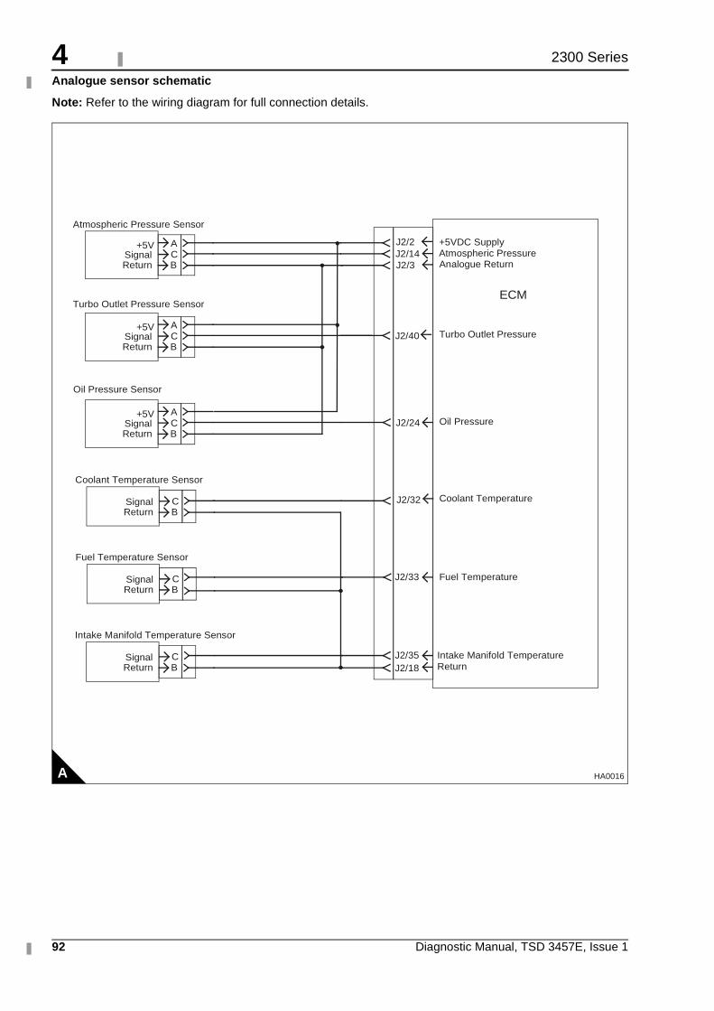
4
92 Diagnostic Manual, TSD 3457E, Issue 1
2300 Series
Analogue sensor schematic
Note: Refer to the wiring diagram for full connection details.
A
AC
+5VSignal
BReturn
AC
+5VSignal
BReturn
AC
+5VSignal
BReturn
Atmospheric Pressure Sensor
J2/2J2/14J2/3
J2/24
J2/32
J2/33
J2/35
J2/40
Turbo Outlet Pressure Sensor
Oil Pressure Sensor
J2/18
+5VDC SupplyAtmospheric PressureAnalogue Return
Turbo Outlet Pressure
Oil Pressure
Coolant Temperature
Fuel Temperature
Intake Manifold Temperature
ECM
Return
Intake Manifold Temperature Sensor
CSignalBReturn
Coolant Temperature Sensor
CSignalBReturn
Fuel Temperature Sensor
CSignalBReturn
HA0016
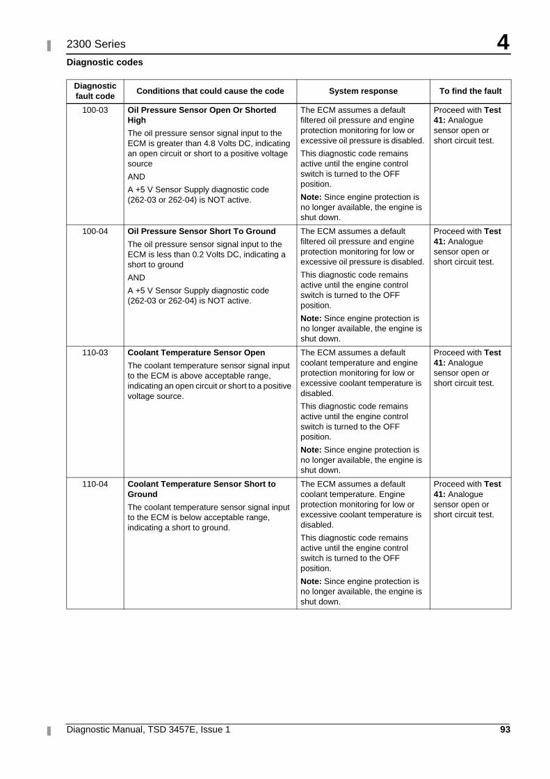
4
Diagnostic Manual, TSD 3457E, Issue 1 93
2300 Series
Diagnostic codes
Diagnostic fault code
Conditions that could cause the code System response To find the fault
100-03 Oil Pressure Sensor Open Or Shorted High
The oil pressure sensor signal input to the ECM is greater than 4.8 Volts DC, indicating an open circuit or short to a positive voltage source
AND
A +5 V Sensor Supply diagnostic code (262-03 or 262-04) is NOT active.
The ECM assumes a default filtered oil pressure and engine protection monitoring for low or excessive oil pressure is disabled.
This diagnostic code remains active until the engine control switch is turned to the OFF position.
Note: Since engine protection is no longer available, the engine is shut down.
Proceed with Test 41: Analogue sensor open or short circuit test.
100-04 Oil Pressure Sensor Short To Ground
The oil pressure sensor signal input to the ECM is less than 0.2 Volts DC, indicating a short to ground
AND
A +5 V Sensor Supply diagnostic code (262-03 or 262-04) is NOT active.
The ECM assumes a default filtered oil pressure and engine protection monitoring for low or excessive oil pressure is disabled.
This diagnostic code remains active until the engine control switch is turned to the OFF position.
Note: Since engine protection is no longer available, the engine is shut down.
Proceed with Test 41: Analogue sensor open or short circuit test.
110-03 Coolant Temperature Sensor Open
The coolant temperature sensor signal input to the ECM is above acceptable range, indicating an open circuit or short to a positive voltage source.
The ECM assumes a default coolant temperature and engine protection monitoring for low or excessive coolant temperature is disabled.
This diagnostic code remains active until the engine control switch is turned to the OFF position.
Note: Since engine protection is no longer available, the engine is shut down.
Proceed with Test 41: Analogue sensor open or short circuit test.
110-04 Coolant Temperature Sensor Short to Ground
The coolant temperature sensor signal input to the ECM is below acceptable range, indicating a short to ground.
The ECM assumes a default coolant temperature. Engine protection monitoring for low or excessive coolant temperature is disabled.
This diagnostic code remains active until the engine control switch is turned to the OFF position.
Note: Since engine protection is no longer available, the engine is shut down.
Proceed with Test 41: Analogue sensor open or short circuit test.
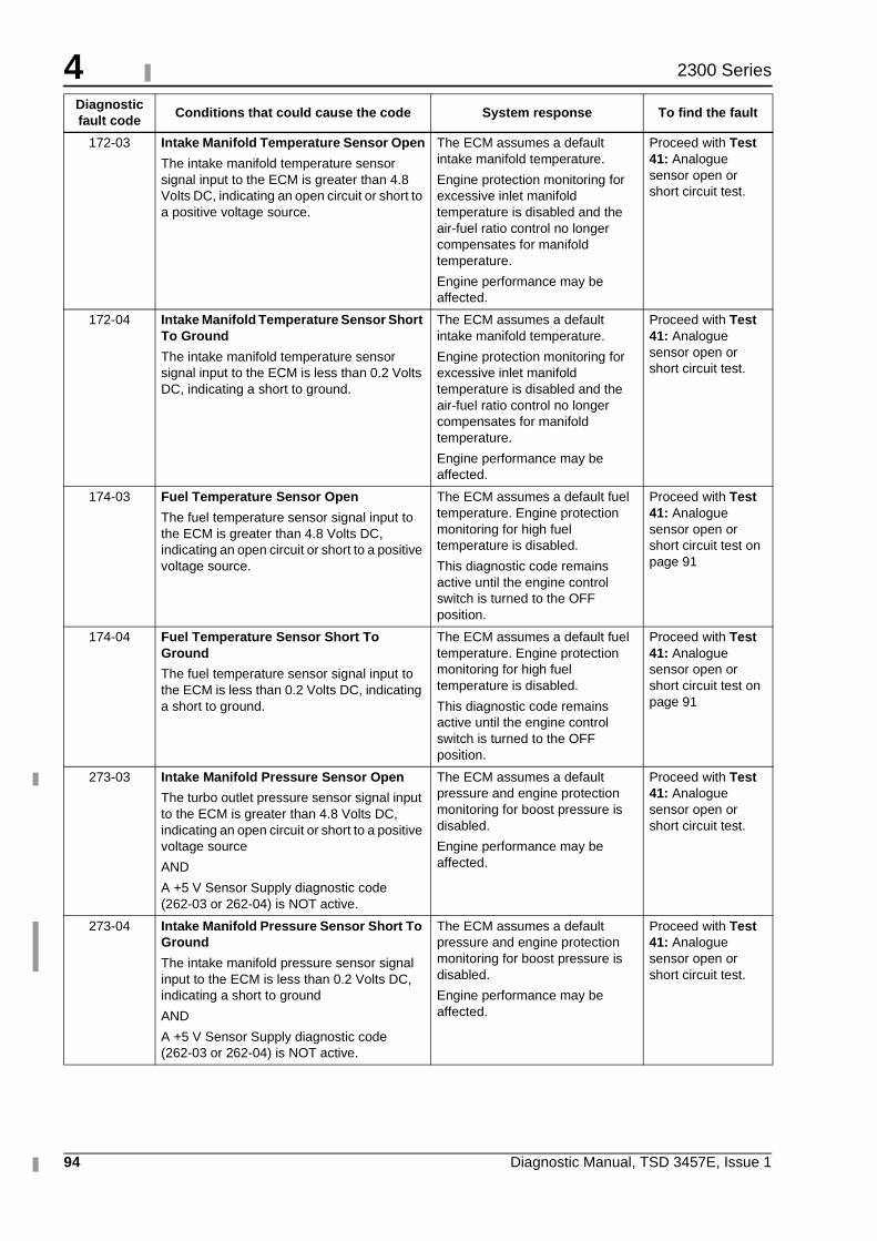
4
94 Diagnostic Manual, TSD 3457E, Issue 1
2300 Series
172-03 Intake Manifold Temperature Sensor Open
The intake manifold temperature sensor signal input to the ECM is greater than 4.8 Volts DC, indicating an open circuit or short to a positive voltage source.
The ECM assumes a default intake manifold temperature.
Engine protection monitoring for excessive inlet manifold temperature is disabled and the air-fuel ratio control no longer compensates for manifold temperature.
Engine performance may be affected.
Proceed with Test 41: Analogue sensor open or short circuit test.
172-04 Intake Manifold Temperature Sensor Short To Ground
The intake manifold temperature sensor signal input to the ECM is less than 0.2 Volts DC, indicating a short to ground.
The ECM assumes a default intake manifold temperature.
Engine protection monitoring for excessive inlet manifold temperature is disabled and the air-fuel ratio control no longer compensates for manifold temperature.
Engine performance may be affected.
Proceed with Test 41: Analogue sensor open or short circuit test.
174-03 Fuel Temperature Sensor Open
The fuel temperature sensor signal input to the ECM is greater than 4.8 Volts DC, indicating an open circuit or short to a positive voltage source.
The ECM assumes a default fuel temperature. Engine protection monitoring for high fuel temperature is disabled.
This diagnostic code remains active until the engine control switch is turned to the OFF position.
Proceed with Test 41: Analogue sensor open or short circuit test on page 91
174-04 Fuel Temperature Sensor Short To Ground
The fuel temperature sensor signal input to the ECM is less than 0.2 Volts DC, indicating a short to ground.
The ECM assumes a default fuel temperature. Engine protection monitoring for high fuel temperature is disabled.
This diagnostic code remains active until the engine control switch is turned to the OFF position.
Proceed with Test 41: Analogue sensor open or short circuit test on page 91
273-03 Intake Manifold Pressure Sensor Open
The turbo outlet pressure sensor signal input to the ECM is greater than 4.8 Volts DC, indicating an open circuit or short to a positive voltage source
AND
A +5 V Sensor Supply diagnostic code (262-03 or 262-04) is NOT active.
The ECM assumes a default pressure and engine protection monitoring for boost pressure is disabled.
Engine performance may be affected.
Proceed with Test 41: Analogue sensor open or short circuit test.
273-04 Intake Manifold Pressure Sensor Short To Ground
The intake manifold pressure sensor signal input to the ECM is less than 0.2 Volts DC, indicating a short to ground
AND
A +5 V Sensor Supply diagnostic code (262-03 or 262-04) is NOT active.
The ECM assumes a default pressure and engine protection monitoring for boost pressure is disabled.
Engine performance may be affected.
Proceed with Test 41: Analogue sensor open or short circuit test.
Diagnostic fault code
Conditions that could cause the code System response To find the fault
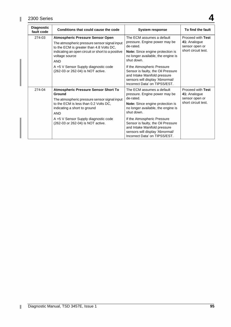
4
Diagnostic Manual, TSD 3457E, Issue 1 95
2300 Series
274-03 Atmospheric Pressure Sensor Open
The atmospheric pressure sensor signal input to the ECM is greater than 4.8 Volts DC, indicating an open circuit or short to a positive voltage source
AND
A +5 V Sensor Supply diagnostic code (262-03 or 262-04) is NOT active.
The ECM assumes a default pressure. Engine power may be de-rated.
Note: Since engine protection is no longer available, the engine is shut down.
If the Atmospheric Pressure Sensor is faulty, the Oil Pressure and Intake Manifold pressure sensors will display ’Abnormal/Incorrect Data’ on TIPSS/EST.
Proceed with Test 41: Analogue sensor open or short circuit test.
274-04 Atmospheric Pressure Sensor Short To Ground
The atmospheric pressure sensor signal input to the ECM is less than 0.2 Volts DC, indicating a short to ground
AND
A +5 V Sensor Supply diagnostic code (262-03 or 262-04) is NOT active.
The ECM assumes a default pressure. Engine power may be de-rated.
Note: Since engine protection is no longer available, the engine is shut down.
If the Atmospheric Pressure Sensor is faulty, the Oil Pressure and Intake Manifold pressure sensors will display ’Abnormal/Incorrect Data’ on TIPSS/EST.
Proceed with Test 41: Analogue sensor open or short circuit test.
Diagnostic fault code
Conditions that could cause the code System response To find the fault
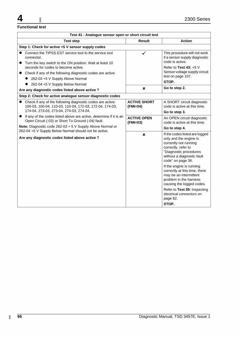
4
96 Diagnostic Manual, TSD 3457E, Issue 1
2300 Series
Functional test
Test 41 - Analogue sensor open or short circuit test
Test step Result Action
Step 1: Check for active +5 V sensor supply codes
� Connect the TIPSS-EST service tool to the service tool connector.
� Turn the key switch to the ON position. Wait at least 10 seconds for codes to become active.
� Check if any of the following diagnostic codes are active:
� 262-03 +5 V Supply Above Normal
� 262-04 +5 V Supply Below Normal
Are any diagnostic codes listed above active ?
� This procedure will not work if a sensor supply diagnostic code is active.
Refer to Test 43: +5 V Sensor voltage supply circuit test on page 107.
STOP.
� Go to step 2.
Step 2: Check for active analogue sensor diagnostic codes
� Check if any of the following diagnostic codes are active: 100-03, 100-04, 110-03, 110-04, 172-03, 172-04, 174-03, 174-04, 273-03, 273-04, 274-03, 274-04.
� If any of the codes listed above are active, determine if it is an Open Circuit (-03) or Short To Ground (-04) fault.
Note: Diagnostic code 262-03 + 5 V Supply Above Normal or 262-04 +5 V Supply Below Normal should not be active.
Are any diagnostic codes listed above active ?
ACTIVE SHORT (FMI=04)
A SHORT circuit diagnostic code is active at this time.
Go to step 3.
ACTIVE OPEN (FMI=03)
An OPEN circuit diagnostic code is active at this time.
Go to step 4.
� If the codes listed are logged only and the engine is currently not running correctly, refer to "Diagnostic procedures without a diagnostic fault code" on page 36.
If the engine is running correctly at this time, there may be an intermittent problem in the harness causing the logged codes.
Refer to Test 39: Inspecting electrical connectors on page 82.
STOP.
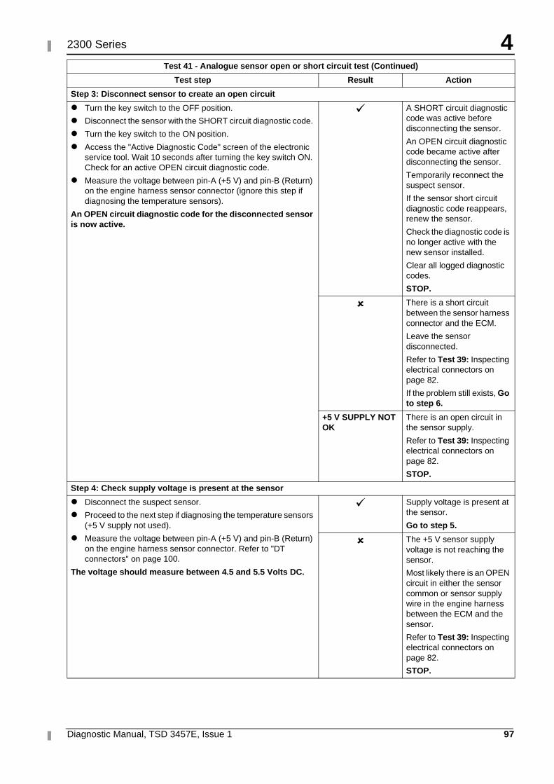
4
Diagnostic Manual, TSD 3457E, Issue 1 97
2300 Series
Step 3: Disconnect sensor to create an open circuit
� Turn the key switch to the OFF position.
� Disconnect the sensor with the SHORT circuit diagnostic code.
� Turn the key switch to the ON position.
� Access the "Active Diagnostic Code" screen of the electronic service tool. Wait 10 seconds after turning the key switch ON. Check for an active OPEN circuit diagnostic code.
� Measure the voltage between pin-A (+5 V) and pin-B (Return) on the engine harness sensor connector (ignore this step if diagnosing the temperature sensors).
An OPEN circuit diagnostic code for the disconnected sensor is now active.
� A SHORT circuit diagnostic code was active before disconnecting the sensor.
An OPEN circuit diagnostic code became active after disconnecting the sensor.
Temporarily reconnect the suspect sensor.
If the sensor short circuit diagnostic code reappears, renew the sensor.
Check the diagnostic code is no longer active with the new sensor installed.
Clear all logged diagnostic codes.
STOP.
� There is a short circuit between the sensor harness connector and the ECM.
Leave the sensor disconnected.
Refer to Test 39: Inspecting electrical connectors on page 82.
If the problem still exists, Go to step 6.
+5 V SUPPLY NOT OK
There is an open circuit in the sensor supply.
Refer to Test 39: Inspecting electrical connectors on page 82.
STOP.
Step 4: Check supply voltage is present at the sensor
� Disconnect the suspect sensor.
� Proceed to the next step if diagnosing the temperature sensors (+5 V supply not used).
� Measure the voltage between pin-A (+5 V) and pin-B (Return) on the engine harness sensor connector. Refer to "DT connectors" on page 100.
The voltage should measure between 4.5 and 5.5 Volts DC.
� Supply voltage is present at the sensor.
Go to step 5.
� The +5 V sensor supply voltage is not reaching the sensor.
Most likely there is an OPEN circuit in either the sensor common or sensor supply wire in the engine harness between the ECM and the sensor.
Refer to Test 39: Inspecting electrical connectors on page 82.
STOP.
Test 41 - Analogue sensor open or short circuit test (Continued)
Test step Result Action
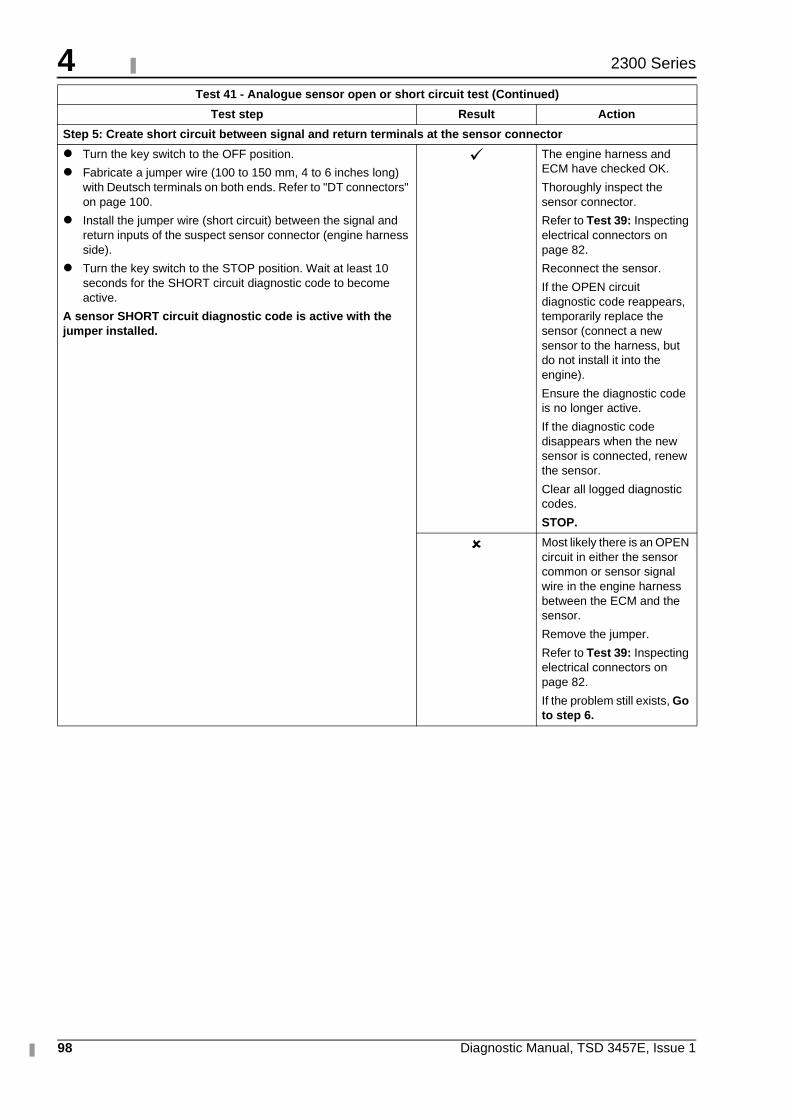
4
98 Diagnostic Manual, TSD 3457E, Issue 1
2300 Series
Step 5: Create short circuit between signal and return terminals at the sensor connector
� Turn the key switch to the OFF position.
� Fabricate a jumper wire (100 to 150 mm, 4 to 6 inches long) with Deutsch terminals on both ends. Refer to "DT connectors" on page 100.
� Install the jumper wire (short circuit) between the signal and return inputs of the suspect sensor connector (engine harness side).
� Turn the key switch to the STOP position. Wait at least 10 seconds for the SHORT circuit diagnostic code to become active.
A sensor SHORT circuit diagnostic code is active with the jumper installed.
� The engine harness and ECM have checked OK.
Thoroughly inspect the sensor connector.
Refer to Test 39: Inspecting electrical connectors on page 82.
Reconnect the sensor.
If the OPEN circuit diagnostic code reappears, temporarily replace the sensor (connect a new sensor to the harness, but do not install it into the engine).
Ensure the diagnostic code is no longer active.
If the diagnostic code disappears when the new sensor is connected, renew the sensor.
Clear all logged diagnostic codes.
STOP.
� Most likely there is an OPEN circuit in either the sensor common or sensor signal wire in the engine harness between the ECM and the sensor.
Remove the jumper.
Refer to Test 39: Inspecting electrical connectors on page 82.
If the problem still exists, Go to step 6.
Test 41 - Analogue sensor open or short circuit test (Continued)
Test step Result Action
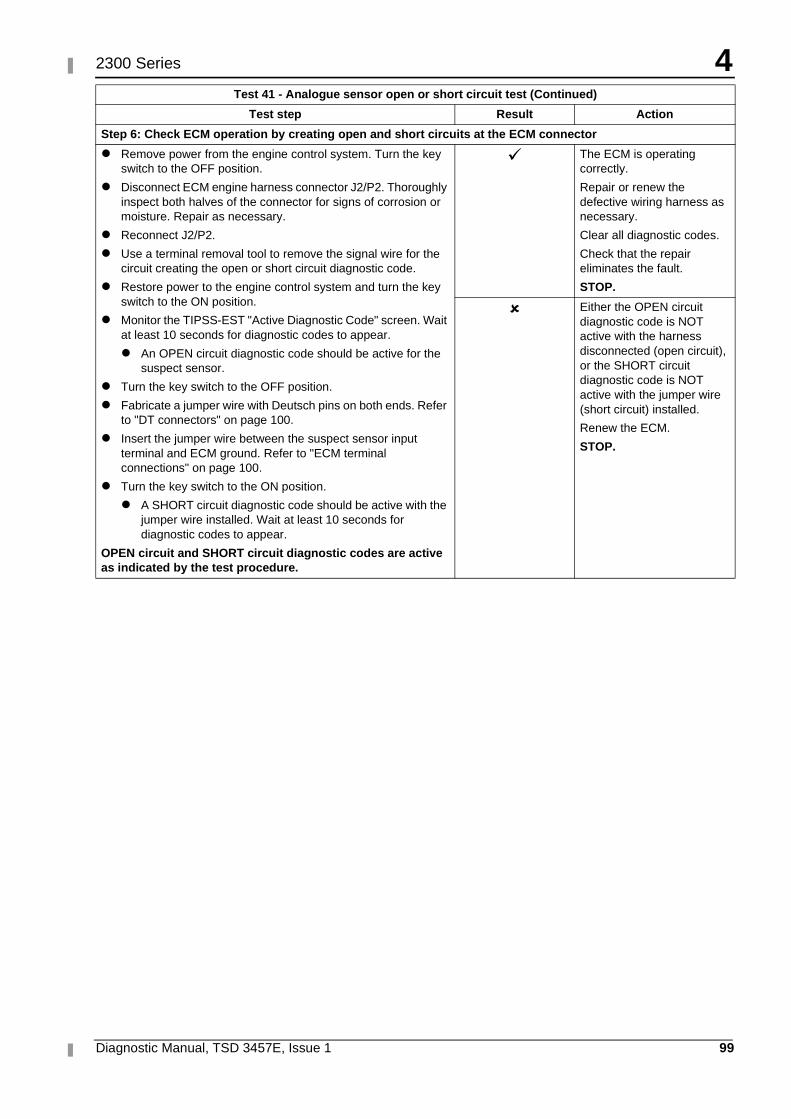
4
Diagnostic Manual, TSD 3457E, Issue 1 99
2300 Series
Step 6: Check ECM operation by creating open and short circuits at the ECM connector
� Remove power from the engine control system. Turn the key switch to the OFF position.
� Disconnect ECM engine harness connector J2/P2. Thoroughly inspect both halves of the connector for signs of corrosion or moisture. Repair as necessary.
� Reconnect J2/P2.
� Use a terminal removal tool to remove the signal wire for the circuit creating the open or short circuit diagnostic code.
� Restore power to the engine control system and turn the key switch to the ON position.
� Monitor the TIPSS-EST "Active Diagnostic Code" screen. Wait at least 10 seconds for diagnostic codes to appear.
� An OPEN circuit diagnostic code should be active for the suspect sensor.
� Turn the key switch to the OFF position.
� Fabricate a jumper wire with Deutsch pins on both ends. Refer to "DT connectors" on page 100.
� Insert the jumper wire between the suspect sensor input terminal and ECM ground. Refer to "ECM terminal connections" on page 100.
� Turn the key switch to the ON position.
� A SHORT circuit diagnostic code should be active with the jumper wire installed. Wait at least 10 seconds for diagnostic codes to appear.
OPEN circuit and SHORT circuit diagnostic codes are active as indicated by the test procedure.
� The ECM is operating correctly.
Repair or renew the defective wiring harness as necessary.
Clear all diagnostic codes.
Check that the repair eliminates the fault.
STOP.
� Either the OPEN circuit diagnostic code is NOT active with the harness disconnected (open circuit), or the SHORT circuit diagnostic code is NOT active with the jumper wire (short circuit) installed.
Renew the ECM.
STOP.
Test 41 - Analogue sensor open or short circuit test (Continued)
Test step Result Action
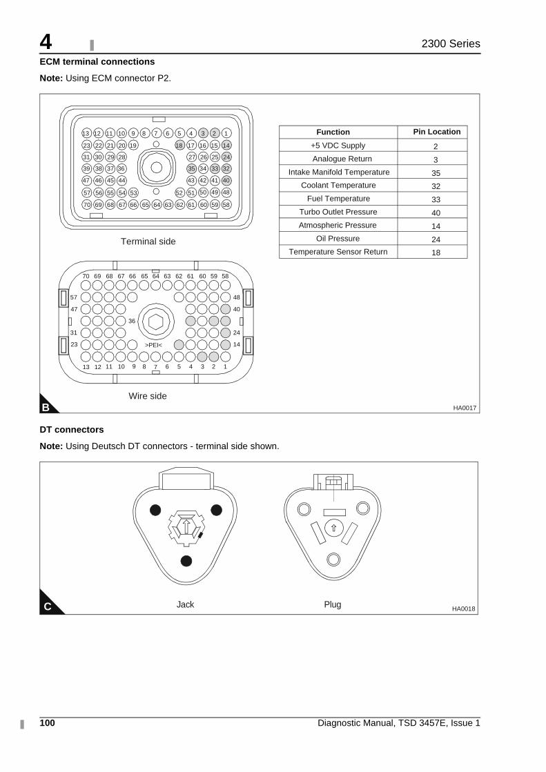
4
100 Diagnostic Manual, TSD 3457E, Issue 1
2300 Series
ECM terminal connections
Note: Using ECM connector P2.
DT connectors
Note: Using Deutsch DT connectors - terminal side shown.
B
1234568910111213
14
24
40
48
23
31
47
57
36
>PEI<
5859606162636566676870
13
64
51525354555657
40414243
32333435
24252627
44454647
36373839
28293031
14151617181920212223
123456789101112
69
5859606162636566676870 6469
7
Terminal side
Wire side
484950
+5 VDC Supply
Analogue Return
Intake Manifold Temperature
Coolant Temperature
Fuel Temperature
Turbo Outlet Pressure
Atmospheric Pressure
Oil Pressure
Temperature Sensor Return
2
3
35
32
33
40
14
24
18
Function Pin Location
HA0017
C Jack Plug HA0018
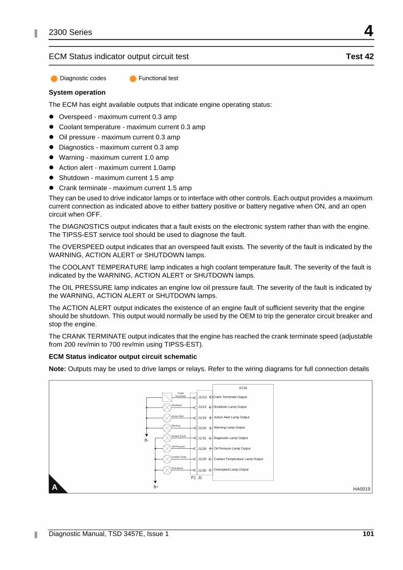
4
Diagnostic Manual, TSD 3457E, Issue 1 101
2300 Series
ECM Status indicator output circuit test Test 42
System operation
The ECM has eight available outputs that indicate engine operating status:
� Overspeed - maximum current 0.3 amp
� Coolant temperature - maximum current 0.3 amp
� Oil pressure - maximum current 0.3 amp
� Diagnostics - maximum current 0.3 amp
� Warning - maximum current 1.0 amp
� Action alert - maximum current 1.0amp
� Shutdown - maximum current 1.5 amp
� Crank terminate - maximum current 1.5 amp
They can be used to drive indicator lamps or to interface with other controls. Each output provides a maximum current connection as indicated above to either battery positive or battery negative when ON, and an open circuit when OFF.
The DIAGNOSTICS output indicates that a fault exists on the electronic system rather than with the engine. The TIPSS-EST service tool should be used to diagnose the fault.
The OVERSPEED output indicates that an overspeed fault exists. The severity of the fault is indicated by the WARNING, ACTION ALERT or SHUTDOWN lamps.
The COOLANT TEMPERATURE lamp indicates a high coolant temperature fault. The severity of the fault is indicated by the WARNING, ACTION ALERT or SHUTDOWN lamps.
The OIL PRESSURE lamp indicates an engine low oil pressure fault. The severity of the fault is indicated by the WARNING, ACTION ALERT or SHUTDOWN lamps.
The ACTION ALERT output indicates the existence of an engine fault of sufficient severity that the engine should be shutdown. This output would normally be used by the OEM to trip the generator circuit breaker and stop the engine.
The CRANK TERMINATE output indicates that the engine has reached the crank terminate speed (adjustable from 200 rev/min to 700 rev/min using TIPSS-EST).
ECM Status indicator output circuit schematic
Note: Outputs may be used to drive lamps or relays. Refer to the wiring diagrams for full connection details
Diagnostic codes Functional test
A HA0019
ECM
J1/10
J1/19
J1/20
J1/31
P1 J1
Shutdown Lamp Output
Action Alert Lamp Output
Warning Lamp Output
Diagnostic Lamp Output
J1/28 Oil Pressure Lamp Output
J1/29 Coolant Temperature Lamp Output
J1/30 Overspeed Lamp Output
B-
B+
Shutdown
Action Alert
Warning
System Fault
Oil Pressure
Coolant Temp
Overspeed
Crank Terminate J1/13 Crank Terminate Output
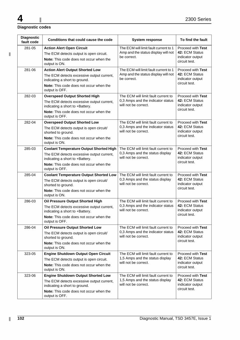
4
102 Diagnostic Manual, TSD 3457E, Issue 1
2300 Series
Diagnostic codes
Diagnostic fault code
Conditions that could cause the code System response To find the fault
281-05 Action Alert Open Circuit
The ECM detects output is open circuit.
Note: This code does not occur when the output is ON.
The ECM will limit fault current to 1 Amp and the status display will not be correct.
Proceed with Test 42: ECM Status indicator output circuit test.
281-06 Action Alert Output Shorted Low
The ECM detects excessive output current, indicating a short to ground.
Note: This code does not occur when the output is OFF.
The ECM will limit fault current to 1 Amp and the status display will not be correct.
Proceed with Test 42: ECM Status indicator output circuit test.
282-03 Overspeed Output Shorted High
The ECM detects excessive output current, indicating a short to +Battery.
Note: This code does not occur when the output is OFF.
The ECM will limit fault current to 0,3 Amps and the indicator status will not be correct.
Proceed with Test 42: ECM Status indicator output circuit test.
282-04 Overspeed Output Shorted Low
The ECM detects output is open circuit/shorted to ground.
Note: This code does not occur when the output is ON.
The ECM will limit fault current to 0,3 Amps and the indicator status will not be correct.
Proceed with Test 42: ECM Status indicator output circuit test.
285-03 Coolant Temperature Output Shorted High
The ECM detects excessive output current, indicating a short to +Battery.
Note: This code does not occur when the output is OFF.
The ECM will limit fault current to 0,3 Amps and the status display will not be correct.
Proceed with Test 42: ECM Status indicator output circuit test.
285-04 Coolant Temperature Output Shorted Low
The ECM detects output is open circuit/shorted to ground.
Note: This code does not occur when the output is ON.
The ECM will limit fault current to 0,3 Amps and the status display will not be correct.
Proceed with Test 42: ECM Status indicator output circuit test.
286-03 Oil Pressure Output Shorted High
The ECM detects excessive output current, indicating a short to +Battery.
Note: This code does not occur when the output is OFF.
The ECM will limit fault current to 0,3 Amps and the indicator status will not be correct.
Proceed with Test 42: ECM Status indicator output circuit test.
286-04 Oil Pressure Output Shorted Low
The ECM detects output is open circuit/shorted to ground.
Note: This code does not occur when the output is ON.
The ECM will limit fault current to 0,3 Amps and the indicator status will not be correct.
Proceed with Test 42: ECM Status indicator output circuit test.
323-05 Engine Shutdown Output Open Circuit
The ECM detects output is open circuit.
Note: This code does not occur when the output is ON.
The ECM will limit fault current to 1,5 Amps and the status display will not be correct.
Proceed with Test 42: ECM Status indicator output circuit test.
323-06 Engine Shutdown Output Shorted Low
The ECM detects excessive output current, indicating a short to ground.
Note: This code does not occur when the output is OFF.
The ECM will limit fault current to 1,5 Amps and the status display will not be correct.
Proceed with Test 42: ECM Status indicator output circuit test.
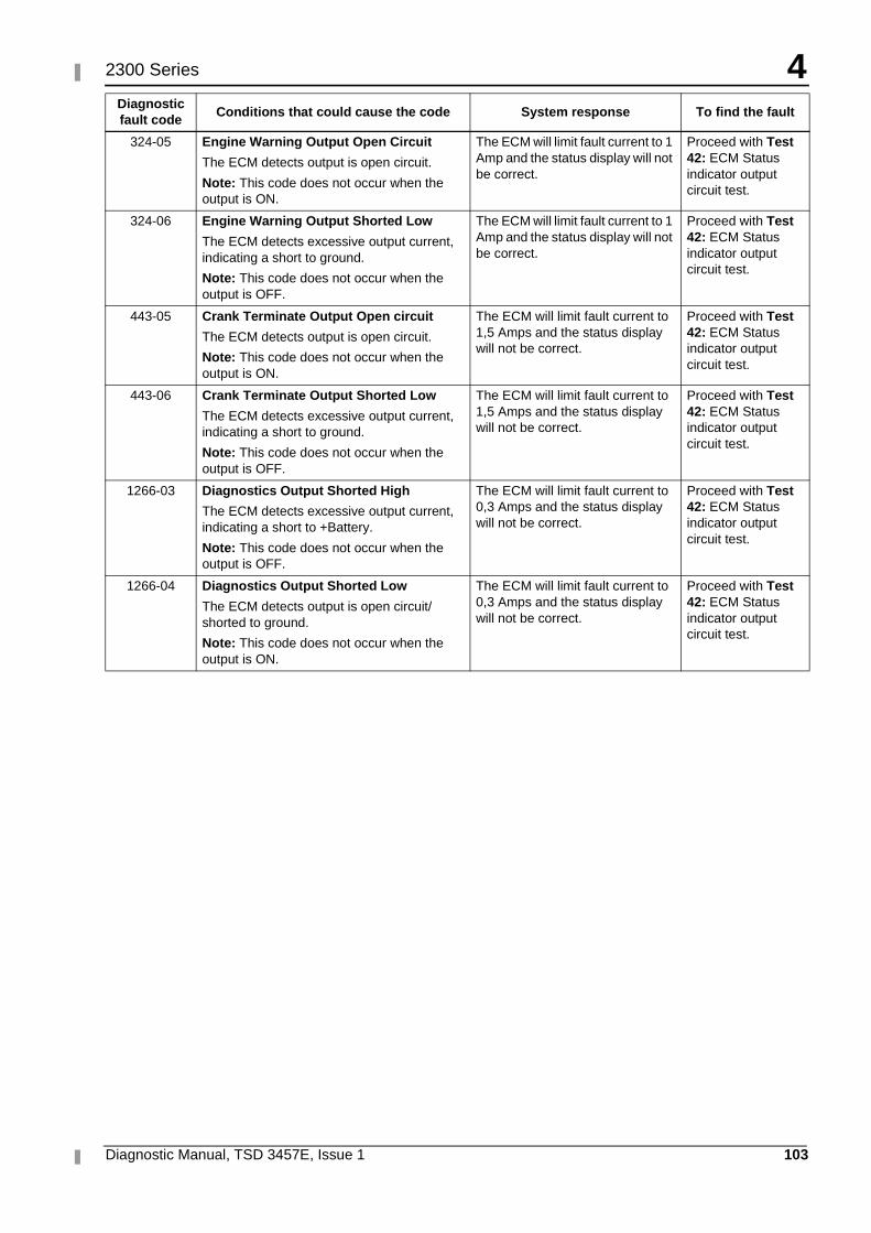
4
Diagnostic Manual, TSD 3457E, Issue 1 103
2300 Series
324-05 Engine Warning Output Open Circuit
The ECM detects output is open circuit.
Note: This code does not occur when the output is ON.
The ECM will limit fault current to 1 Amp and the status display will not be correct.
Proceed with Test 42: ECM Status indicator output circuit test.
324-06 Engine Warning Output Shorted Low
The ECM detects excessive output current, indicating a short to ground.
Note: This code does not occur when the output is OFF.
The ECM will limit fault current to 1 Amp and the status display will not be correct.
Proceed with Test 42: ECM Status indicator output circuit test.
443-05 Crank Terminate Output Open circuit
The ECM detects output is open circuit.
Note: This code does not occur when the output is ON.
The ECM will limit fault current to 1,5 Amps and the status display will not be correct.
Proceed with Test 42: ECM Status indicator output circuit test.
443-06 Crank Terminate Output Shorted Low
The ECM detects excessive output current, indicating a short to ground.
Note: This code does not occur when the output is OFF.
The ECM will limit fault current to 1,5 Amps and the status display will not be correct.
Proceed with Test 42: ECM Status indicator output circuit test.
1266-03 Diagnostics Output Shorted High
The ECM detects excessive output current, indicating a short to +Battery.
Note: This code does not occur when the output is OFF.
The ECM will limit fault current to 0,3 Amps and the status display will not be correct.
Proceed with Test 42: ECM Status indicator output circuit test.
1266-04 Diagnostics Output Shorted Low
The ECM detects output is open circuit/shorted to ground.
Note: This code does not occur when the output is ON.
The ECM will limit fault current to 0,3 Amps and the status display will not be correct.
Proceed with Test 42: ECM Status indicator output circuit test.
Diagnostic fault code
Conditions that could cause the code System response To find the fault
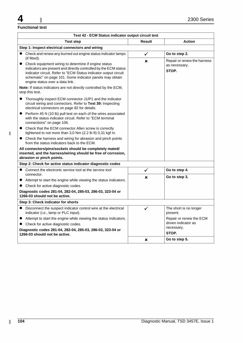
4
104 Diagnostic Manual, TSD 3457E, Issue 1
2300 Series
Functional test
Test 42 - ECM Status indicator output circuit test
Test step Result Action
Step 1: Inspect electrical connectors and wiring
� Check and renew any burned out engine status indicator lamps (if fitted).
� Check equipment wiring to determine if engine status indicators are present and directly controlled by the ECM status indicator circuit. Refer to "ECM Status indicator output circuit schematic" on page 101. Some indicator panels may obtain engine status over a data link.
Note: If status indicators are not directly controlled by the ECM, stop this test.
� Thoroughly inspect ECM connector J1/P1 and the indicator circuit wiring and connectors. Refer to Test 39: Inspecting electrical connectors on page 82 for details.
� Perform 45 N (10 lb) pull test on each of the wires associated with the status indicator circuit. Refer to "ECM terminal connections" on page 106.
� Check that the ECM connector Allen screw is correctly tightened to not more than 3,0 Nm (2.2 lb ft) 0,31 kgf m.
� Check the harness and wiring for abrasion and pinch points from the status indicators back to the ECM.
All connectors/pins/sockets should be completely mated/inserted, and the harness/wiring should be free of corrosion, abrasion or pinch points.
� Go to step 2.
� Repair or renew the harness as necessary.
STOP.
Step 2: Check for active status indicator diagnostic codes
� Connect the electronic service tool at the service tool connector.
� Attempt to start the engine while viewing the status indicators.
� Check for active diagnostic codes.
Diagnostic codes 281-04, 282-04, 285-03, 286-03, 323-04 or 1266-03 should not be active.
� Go to step 4.
� Go to step 3.
Step 3: Check indicator for shorts
� Disconnect the suspect indicator control wire at the electrical indicator (i.e., lamp or PLC input).
� Attempt to start the engine while viewing the status indicators.
� Check for active diagnostic codes.
Diagnostic codes 281-04, 282-04, 285-03, 286-03, 323-04 or 1266-03 should not be active.
� The short is no longer present.
Repair or renew the ECM driven indicator as necessary.
STOP.
� Go to step 5.
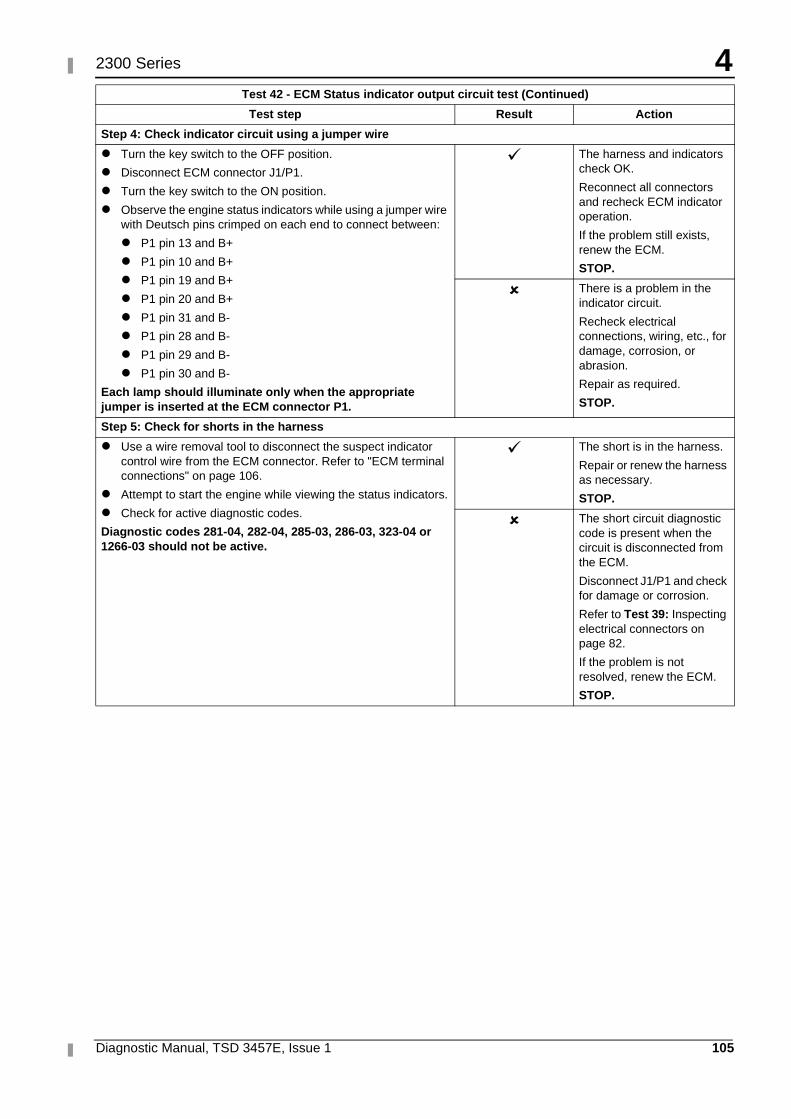
4
Diagnostic Manual, TSD 3457E, Issue 1 105
2300 Series
Step 4: Check indicator circuit using a jumper wire
� Turn the key switch to the OFF position.
� Disconnect ECM connector J1/P1.
� Turn the key switch to the ON position.
� Observe the engine status indicators while using a jumper wire with Deutsch pins crimped on each end to connect between:
� P1 pin 13 and B+
� P1 pin 10 and B+
� P1 pin 19 and B+
� P1 pin 20 and B+
� P1 pin 31 and B-
� P1 pin 28 and B-
� P1 pin 29 and B-
� P1 pin 30 and B-
Each lamp should illuminate only when the appropriate jumper is inserted at the ECM connector P1.
� The harness and indicators check OK.
Reconnect all connectors and recheck ECM indicator operation.
If the problem still exists, renew the ECM.
STOP.
� There is a problem in the indicator circuit.
Recheck electrical connections, wiring, etc., for damage, corrosion, or abrasion.
Repair as required.
STOP.
Step 5: Check for shorts in the harness
� Use a wire removal tool to disconnect the suspect indicator control wire from the ECM connector. Refer to "ECM terminal connections" on page 106.
� Attempt to start the engine while viewing the status indicators.
� Check for active diagnostic codes.
Diagnostic codes 281-04, 282-04, 285-03, 286-03, 323-04 or 1266-03 should not be active.
� The short is in the harness.
Repair or renew the harness as necessary.
STOP.
� The short circuit diagnostic code is present when the circuit is disconnected from the ECM.
Disconnect J1/P1 and check for damage or corrosion.
Refer to Test 39: Inspecting electrical connectors on page 82.
If the problem is not resolved, renew the ECM.
STOP.
Test 42 - ECM Status indicator output circuit test (Continued)
Test step Result Action
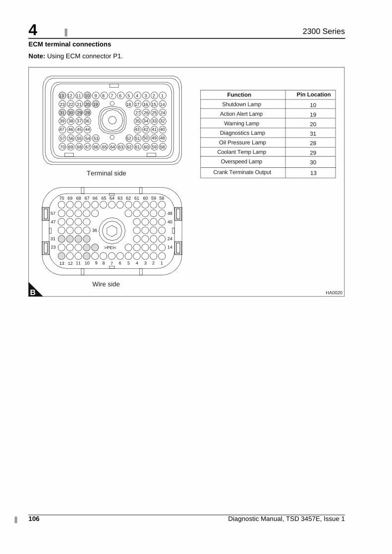
4
106 Diagnostic Manual, TSD 3457E, Issue 1
2300 Series
ECM terminal connections
Note: Using ECM connector P1.
B
1234568910111213
14
24
40
48
23
31
47
57
36
>PEI<
5859606162636566676870 64
51525354555657
40414243
32333435
24252627
44454647
36373839
28293031
141517181920212223
123456789101112
69
5859606162636566676870 6469
7
Terminal side
Wire side
484950
Shutdown Lamp
Action Alert Lamp
Warning Lamp
Diagnostics Lamp
Oil Pressure Lamp
Coolant Temp Lamp
Overspeed Lamp
10
19
20
31
28
29
30
Function Pin Location
16
13
Crank Terminate Output 13
HA0020
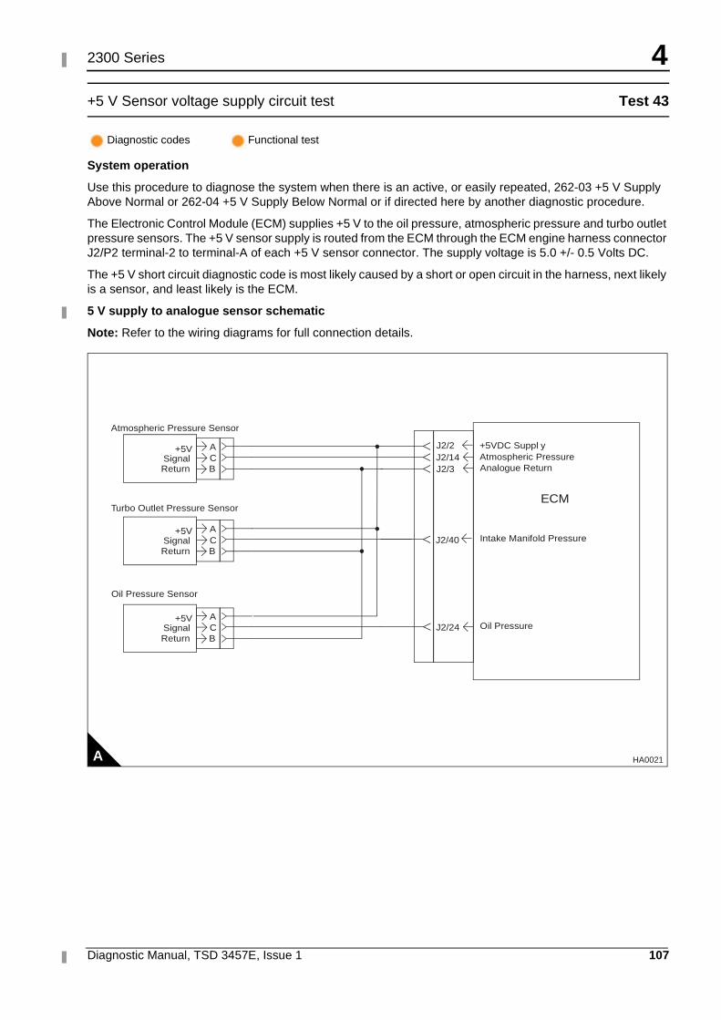
4
Diagnostic Manual, TSD 3457E, Issue 1 107
2300 Series
+5 V Sensor voltage supply circuit test Test 43
System operation
Use this procedure to diagnose the system when there is an active, or easily repeated, 262-03 +5 V Supply Above Normal or 262-04 +5 V Supply Below Normal or if directed here by another diagnostic procedure.
The Electronic Control Module (ECM) supplies +5 V to the oil pressure, atmospheric pressure and turbo outlet pressure sensors. The +5 V sensor supply is routed from the ECM through the ECM engine harness connector J2/P2 terminal-2 to terminal-A of each +5 V sensor connector. The supply voltage is 5.0 +/- 0.5 Volts DC.
The +5 V short circuit diagnostic code is most likely caused by a short or open circuit in the harness, next likely is a sensor, and least likely is the ECM.
5 V supply to analogue sensor schematic
Note: Refer to the wiring diagrams for full connection details.
Diagnostic codes Functional test
A
AC
+5VSignal
BReturn
AC
+5VSignal
BReturn
AC
+5VSignal
BReturn
Atmospheric Pressure Sensor
J2/2J2/14J2/3
J2/24
J2/40
Turbo Outlet Pressure Sensor
Oil Pressure Sensor
+5VDC Suppl yAtmospheric PressureAnalogue Return
Intake Manifold Pressure
Oil Pressure
ECM
HA0021
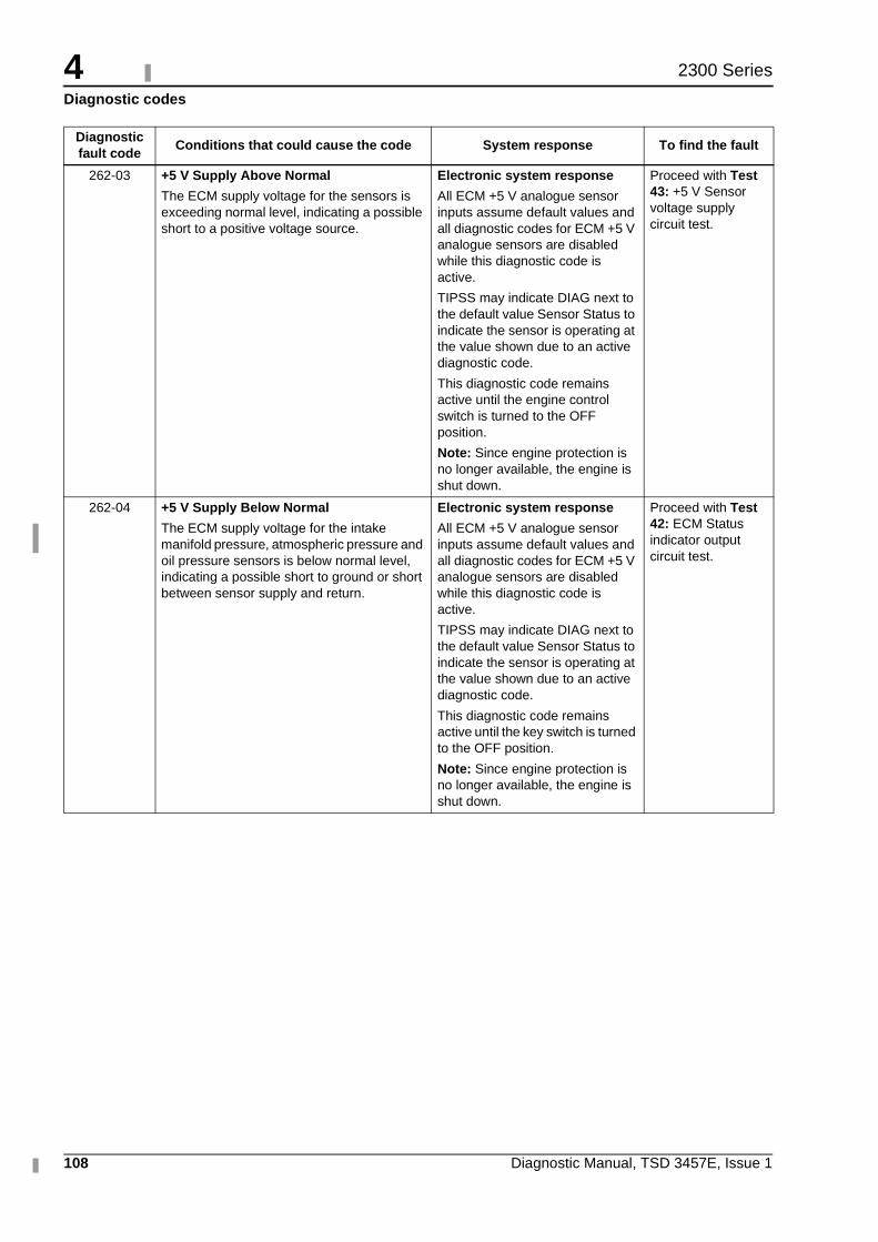
4
108 Diagnostic Manual, TSD 3457E, Issue 1
2300 Series
Diagnostic codes
Diagnostic fault code
Conditions that could cause the code System response To find the fault
262-03 +5 V Supply Above Normal
The ECM supply voltage for the sensors is exceeding normal level, indicating a possible short to a positive voltage source.
Electronic system response
All ECM +5 V analogue sensor inputs assume default values and all diagnostic codes for ECM +5 V analogue sensors are disabled while this diagnostic code is active.
TIPSS may indicate DIAG next to the default value Sensor Status to indicate the sensor is operating at the value shown due to an active diagnostic code.
This diagnostic code remains active until the engine control switch is turned to the OFF position.
Note: Since engine protection is no longer available, the engine is shut down.
Proceed with Test 43: +5 V Sensor voltage supply circuit test.
262-04 +5 V Supply Below Normal
The ECM supply voltage for the intake manifold pressure, atmospheric pressure and oil pressure sensors is below normal level, indicating a possible short to ground or short between sensor supply and return.
Electronic system response
All ECM +5 V analogue sensor inputs assume default values and all diagnostic codes for ECM +5 V analogue sensors are disabled while this diagnostic code is active.
TIPSS may indicate DIAG next to the default value Sensor Status to indicate the sensor is operating at the value shown due to an active diagnostic code.
This diagnostic code remains active until the key switch is turned to the OFF position.
Note: Since engine protection is no longer available, the engine is shut down.
Proceed with Test 42: ECM Status indicator output circuit test.
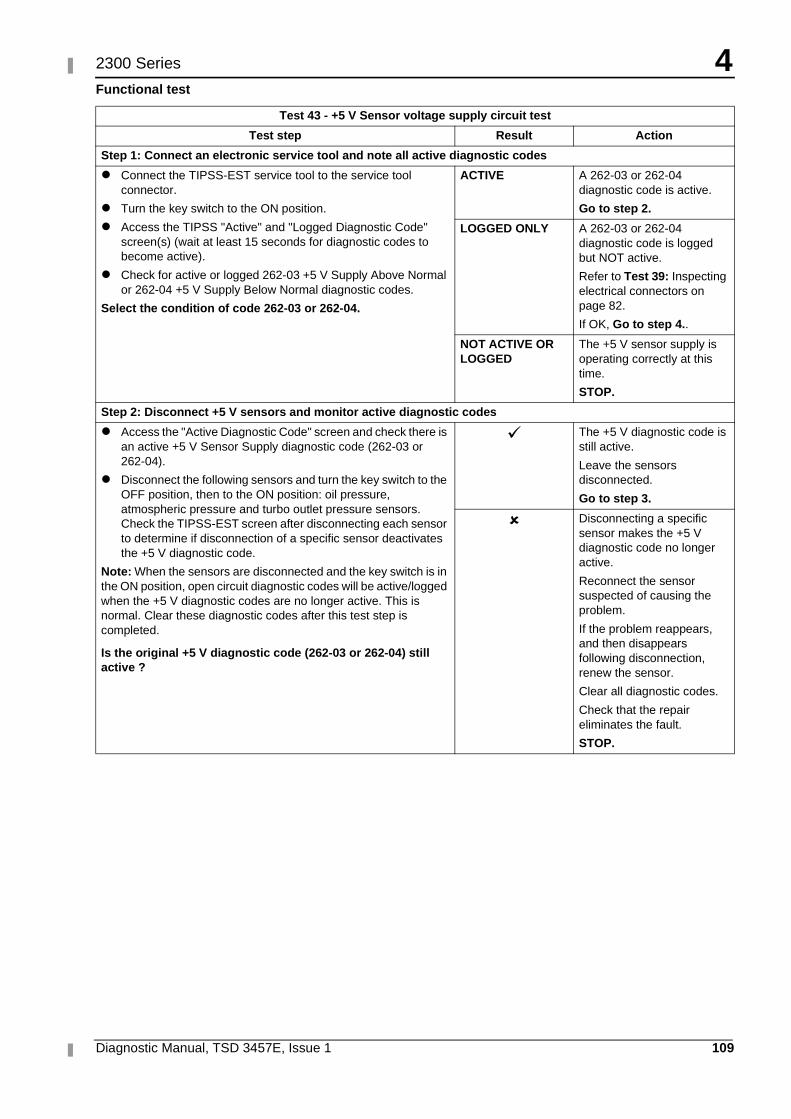
4
Diagnostic Manual, TSD 3457E, Issue 1 109
2300 Series
Functional test
Test 43 - +5 V Sensor voltage supply circuit test
Test step Result Action
Step 1: Connect an electronic service tool and note all active diagnostic codes
� Connect the TIPSS-EST service tool to the service tool connector.
� Turn the key switch to the ON position.
� Access the TIPSS "Active" and "Logged Diagnostic Code" screen(s) (wait at least 15 seconds for diagnostic codes to become active).
� Check for active or logged 262-03 +5 V Supply Above Normal or 262-04 +5 V Supply Below Normal diagnostic codes.
Select the condition of code 262-03 or 262-04.
ACTIVE A 262-03 or 262-04 diagnostic code is active.
Go to step 2.
LOGGED ONLY A 262-03 or 262-04 diagnostic code is logged but NOT active.
Refer to Test 39: Inspecting electrical connectors on page 82.
If OK, Go to step 4..
NOT ACTIVE OR LOGGED
The +5 V sensor supply is operating correctly at this time.
STOP.
Step 2: Disconnect +5 V sensors and monitor active diagnostic codes
� Access the "Active Diagnostic Code" screen and check there is an active +5 V Sensor Supply diagnostic code (262-03 or 262-04).
� Disconnect the following sensors and turn the key switch to the OFF position, then to the ON position: oil pressure, atmospheric pressure and turbo outlet pressure sensors. Check the TIPSS-EST screen after disconnecting each sensor to determine if disconnection of a specific sensor deactivates the +5 V diagnostic code.
Note: When the sensors are disconnected and the key switch is in the ON position, open circuit diagnostic codes will be active/logged when the +5 V diagnostic codes are no longer active. This is normal. Clear these diagnostic codes after this test step is completed.
Is the original +5 V diagnostic code (262-03 or 262-04) still active ?
� The +5 V diagnostic code is still active.
Leave the sensors disconnected.
Go to step 3.
� Disconnecting a specific sensor makes the +5 V diagnostic code no longer active.
Reconnect the sensor suspected of causing the problem.
If the problem reappears, and then disappears following disconnection, renew the sensor.
Clear all diagnostic codes.
Check that the repair eliminates the fault.
STOP.
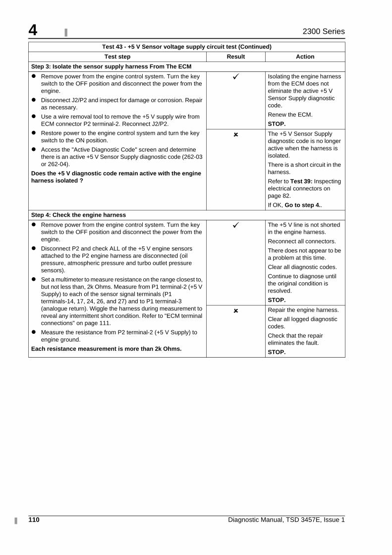
4
110 Diagnostic Manual, TSD 3457E, Issue 1
2300 Series
Step 3: Isolate the sensor supply harness From The ECM
� Remove power from the engine control system. Turn the key switch to the OFF position and disconnect the power from the engine.
� Disconnect J2/P2 and inspect for damage or corrosion. Repair as necessary.
� Use a wire removal tool to remove the +5 V supply wire from ECM connector P2 terminal-2. Reconnect J2/P2.
� Restore power to the engine control system and turn the key switch to the ON position.
� Access the "Active Diagnostic Code" screen and determine there is an active +5 V Sensor Supply diagnostic code (262-03 or 262-04).
Does the +5 V diagnostic code remain active with the engine harness isolated ?
� Isolating the engine harness from the ECM does not eliminate the active +5 V Sensor Supply diagnostic code.
Renew the ECM.
STOP.
� The +5 V Sensor Supply diagnostic code is no longer active when the harness is isolated.
There is a short circuit in the harness.
Refer to Test 39: Inspecting electrical connectors on page 82.
If OK, Go to step 4..
Step 4: Check the engine harness
� Remove power from the engine control system. Turn the key switch to the OFF position and disconnect the power from the engine.
� Disconnect P2 and check ALL of the +5 V engine sensors attached to the P2 engine harness are disconnected (oil pressure, atmospheric pressure and turbo outlet pressure sensors).
� Set a multimeter to measure resistance on the range closest to, but not less than, 2k Ohms. Measure from P1 terminal-2 (+5 V Supply) to each of the sensor signal terminals (P1 terminals-14, 17, 24, 26, and 27) and to P1 terminal-3 (analogue return). Wiggle the harness during measurement to reveal any intermittent short condition. Refer to "ECM terminal connections" on page 111.
� Measure the resistance from P2 terminal-2 (+5 V Supply) to engine ground.
Each resistance measurement is more than 2k Ohms.
� The +5 V line is not shorted in the engine harness.
Reconnect all connectors.
There does not appear to be a problem at this time.
Clear all diagnostic codes.
Continue to diagnose until the original condition is resolved.
STOP.
� Repair the engine harness.
Clear all logged diagnostic codes.
Check that the repair eliminates the fault.
STOP.
Test 43 - +5 V Sensor voltage supply circuit test (Continued)
Test step Result Action
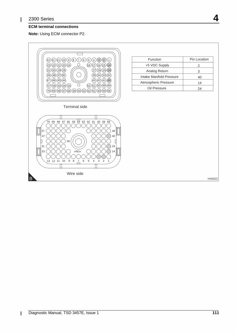
4
Diagnostic Manual, TSD 3457E, Issue 1 111
2300 Series
ECM terminal connections
Note: Using ECM connector P2.
B
1234568910111213
14
24
40
48
23
31
47
57
36
>PEI<
5859606162636566676870
13
64
51525354555657
40414243
32333435
24252627
44454647
36373839
28293031
14151617181920212223
123456789101112
69
5859606162636566676870 6469
7
Terminal side
Wire side
484950
+5 VDC Supply
Analog Return
Intake Manifold Pressure
Atmospheric Pressure
Oil Pressure
2
3
40
14
24
Function Pin Location
HA0022
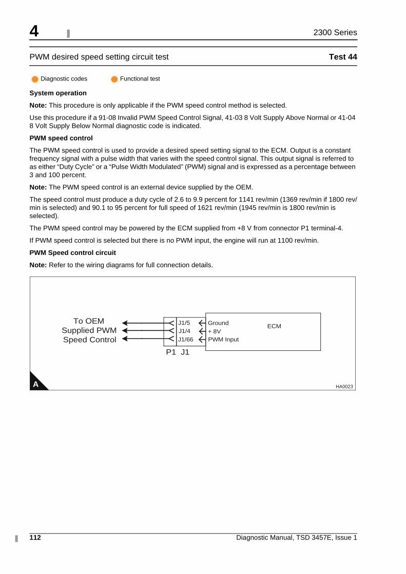
4
112 Diagnostic Manual, TSD 3457E, Issue 1
2300 Series
PWM desired speed setting circuit test Test 44
System operation
Note: This procedure is only applicable if the PWM speed control method is selected.
Use this procedure if a 91-08 Invalid PWM Speed Control Signal, 41-03 8 Volt Supply Above Normal or 41-04 8 Volt Supply Below Normal diagnostic code is indicated.
PWM speed control
The PWM speed control is used to provide a desired speed setting signal to the ECM. Output is a constant frequency signal with a pulse width that varies with the speed control signal. This output signal is referred to as either “Duty Cycle” or a “Pulse Width Modulated” (PWM) signal and is expressed as a percentage between 3 and 100 percent.
Note: The PWM speed control is an external device supplied by the OEM.
The speed control must produce a duty cycle of 2.6 to 9.9 percent for 1141 rev/min (1369 rev/min if 1800 rev/min is selected) and 90.1 to 95 percent for full speed of 1621 rev/min (1945 rev/min is 1800 rev/min is selected).
The PWM speed control may be powered by the ECM supplied from +8 V from connector P1 terminal-4.
If PWM speed control is selected but there is no PWM input, the engine will run at 1100 rev/min.
PWM Speed control circuit
Note: Refer to the wiring diagrams for full connection details.
Diagnostic codes Functional test
A
ECMJ1/5J1/4 + 8V
Ground
J1/66 PWM Input
P1 J1
To OEMSupplied PWMSpeed Control
HA0023
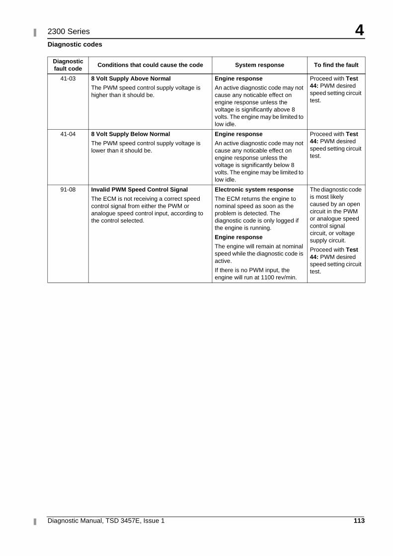
4
Diagnostic Manual, TSD 3457E, Issue 1 113
2300 Series
Diagnostic codes
Diagnostic fault code
Conditions that could cause the code System response To find the fault
41-03 8 Volt Supply Above Normal
The PWM speed control supply voltage is higher than it should be.
Engine response
An active diagnostic code may not cause any noticable effect on engine response unless the voltage is significantly above 8 volts. The engine may be limited to low idle.
Proceed with Test 44: PWM desired speed setting circuit test.
41-04 8 Volt Supply Below Normal
The PWM speed control supply voltage is lower than it should be.
Engine response
An active diagnostic code may not cause any noticable effect on engine response unless the voltage is significantly below 8 volts. The engine may be limited to low idle.
Proceed with Test 44: PWM desired speed setting circuit test.
91-08 Invalid PWM Speed Control Signal
The ECM is not receiving a correct speed control signal from either the PWM or analogue speed control input, according to the control selected.
Electronic system response
The ECM returns the engine to nominal speed as soon as the problem is detected. The diagnostic code is only logged if the engine is running.
Engine response
The engine will remain at nominal speed while the diagnostic code is active.
If there is no PWM input, the engine will run at 1100 rev/min.
The diagnostic code is most likely caused by an open circuit in the PWM or analogue speed control signal circuit, or voltage supply circuit.
Proceed with Test 44: PWM desired speed setting circuit test.
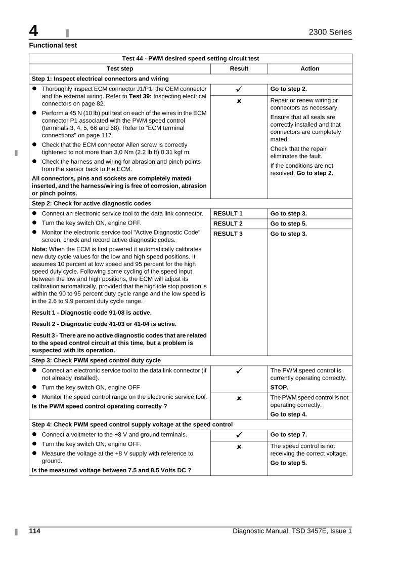
4
114 Diagnostic Manual, TSD 3457E, Issue 1
2300 Series
Functional test
Test 44 - PWM desired speed setting circuit test
Test step Result Action
Step 1: Inspect electrical connectors and wiring
� Thoroughly inspect ECM connector J1/P1, the OEM connector and the external wiring. Refer to Test 39: Inspecting electrical connectors on page 82.
� Perform a 45 N (10 lb) pull test on each of the wires in the ECM connector P1 associated with the PWM speed control (terminals 3, 4, 5, 66 and 68). Refer to "ECM terminal connections" on page 117.
� Check that the ECM connector Allen screw is correctly tightened to not more than 3,0 Nm (2.2 lb ft) 0,31 kgf m.
� Check the harness and wiring for abrasion and pinch points from the sensor back to the ECM.
All connectors, pins and sockets are completely mated/inserted, and the harness/wiring is free of corrosion, abrasion or pinch points.
� Go to step 2.
� Repair or renew wiring or connectors as necessary.
Ensure that all seals are correctly installed and that connectors are completely mated.
Check that the repair eliminates the fault.
If the conditions are not resolved, Go to step 2.
Step 2: Check for active diagnostic codes
� Connect an electronic service tool to the data link connector.
� Turn the key switch ON, engine OFF.
� Monitor the electronic service tool "Active Diagnostic Code" screen, check and record active diagnostic codes.
Note: When the ECM is first powered it automatically calibrates new duty cycle values for the low and high speed positions. It assumes 10 percent at low speed and 95 percent for the high speed duty cycle. Following some cycling of the speed input between the low and high positions, the ECM will adjust its calibration automatically, provided that the high idle stop position is within the 90 to 95 percent duty cycle range and the low speed is in the 2.6 to 9.9 percent duty cycle range.
Result 1 - Diagnostic code 91-08 is active.
Result 2 - Diagnostic code 41-03 or 41-04 is active.
Result 3 - There are no active diagnostic codes that are related to the speed control circuit at this time, but a problem is suspected with its operation.
RESULT 1 Go to step 3.
RESULT 2 Go to step 5.
RESULT 3 Go to step 3.
Step 3: Check PWM speed control duty cycle
� Connect an electronic service tool to the data link connector (if not already installed).
� Turn the key switch ON, engine OFF
� Monitor the speed control range on the electronic service tool.
Is the PWM speed control operating correctly ?
� The PWM speed control is currently operating correctly.
STOP.
� The PWM speed control is not operating correctly.
Go to step 4.
Step 4: Check PWM speed control supply voltage at the speed control
� Connect a voltmeter to the +8 V and ground terminals.
� Turn the key switch ON, engine OFF.
� Measure the voltage at the +8 V supply with reference to ground.
Is the measured voltage between 7.5 and 8.5 Volts DC ?
� Go to step 7.
� The speed control is not receiving the correct voltage.
Go to step 5.
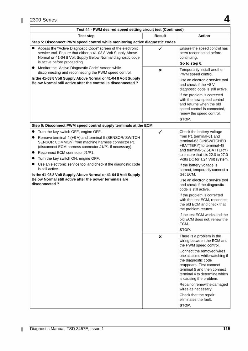
4
Diagnostic Manual, TSD 3457E, Issue 1 115
2300 Series
Step 5: Disconnect PWM speed control while monitoring active diagnostic codes
� Access the "Active Diagnostic Code" screen of the electronic service tool. Ensure that either a 41-03 8 Volt Supply Above Normal or 41-04 8 Volt Supply Below Normal diagnostic code is active before proceeding.
� Monitor the "Active Diagnostic Code" screen while disconnecting and reconnecting the PWM speed control.
Is the 41-03 8 Volt Supply Above Normal or 41-04 8 Volt Supply Below Normal still active after the control is disconnected ?
� Ensure the speed control has been reconnected before continuing.
Go to step 6.
� Temporarily install another PWM speed control.
Use an electronic service tool and check if the +8 V diagnostic code is still active.
If the problem is corrected with the new speed control and returns when the old speed control is connected, renew the speed control.
STOP.
Step 6: Disconnect PWM speed control supply terminals at the ECM
� Turn the key switch OFF, engine OFF.
� Remove terminal-4 (+8 V) and terminal-5 (SENSOR/ SWITCH SENSOR COMMON) from machine harness connector P1 (disconnect ECM harness connector J1/P1 if necessary).
� Reconnect ECM connector J1/P1.
� Turn the key switch ON, engine OFF.
� Use an electronic service tool and check if the diagnostic code is still active.
Is the 41-03 8 Volt Supply Above Normal or 41-04 8 Volt Supply Below Normal still active after the power terminals are disconnected ?
� Check the battery voltage from P1 terminal-61 and terminal-63 (UNSWITCHED +BATTERY) to terminal-48 and terminal-52 (-BATTERY) to ensure that it is 22.0 to 27.0 Volts DC for a 24 Volt system.
If the battery voltage is correct, temporarily connect a test ECM.
Use an electronic service tool and check if the diagnostic code is still active.
If the problem is corrected with the test ECM, reconnect the old ECM and check that the problem returns.
If the test ECM works and the old ECM does not, renew the ECM.
STOP.
� There is a problem in the wiring between the ECM and the PWM speed control.
Connect the removed wires one at a time while watching if the diagnostic code reappears. First connect terminal 5 and then connect terminal 4 to determine which is causing the problem.
Repair or renew the damaged wires as necessary.
Check that the repair eliminates the fault.
STOP.
Test 44 - PWM desired speed setting circuit test (Continued)
Test step Result Action
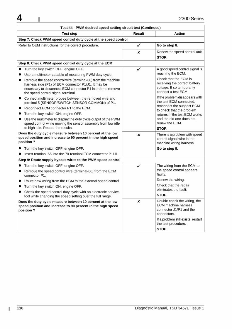
4
116 Diagnostic Manual, TSD 3457E, Issue 1
2300 Series
Step 7: Check PWM speed control duty cycle at the speed control
Refer to OEM instructions for the correct procedure. � Go to step 8.
� Renew the speed control unit.
STOP.
Step 8: Check PWM speed control duty cycle at the ECM
� Turn the key switch OFF, engine OFF.
� Use a multimeter capable of measuring PWM duty cycle.
� Remove the speed control wire (terminal-66) from the machine harness side (P1) of ECM connector P1/J1. It may be necessary to disconnect ECM connector P1 in order to remove the speed control signal terminal.
� Connect multimeter probes between the removed wire and terminal 5 (SENSOR/SWITCH SENSOR COMMON) of P1.
� Reconnect ECM connector P1 to the ECM.
� Turn the key switch ON, engine OFF.
� Use the multimeter to display the duty cycle output of the PWM speed control while moving the sensor assembly from low idle to high idle. Record the results.
Does the duty cycle measure between 10 percent at the low speed position and increase to 90 percent in the high speed position ?
� Turn the key switch OFF, engine OFF.
� Insert terminal-66 into the 70-terminal ECM connector P1/J1.
� A good speed control signal is reaching the ECM.
Check that the ECM is receiving the correct battery voltage. If so temporarily connect a test ECM.
If the problem disappears with the test ECM connected, reconnect the suspect ECM to check that the problem returns. If the test ECM works and the old one does not, renew the ECM.
STOP.
� There is a problem with speed control signal wire in the machine wiring harness.
Go to step 9.
Step 9: Route supply bypass wires to the PWM speed control
� Turn the key switch OFF, engine OFF.
� Remove the speed control wire (terminal-66) from the ECM connector P1.
� Route new wiring from the ECM to the external speed control.
� Turn the key switch ON, engine OFF.
� Check the speed control duty cycle with an electronic service tool while changing the speed setting over the full range.
Does the duty cycle measure between 10 percent at the low speed position and increase to 90 percent in the high speed position ?
� The wiring from the ECM to the speed control appears faulty.
Renew the wiring.
Check that the repair eliminates the fault.
STOP.
� Double check the wiring, the ECM machine harness connector J1/P1 and the connectors.
If a problem still exists, restart the test procedure.
STOP.
Test 44 - PWM desired speed setting circuit test (Continued)
Test step Result Action
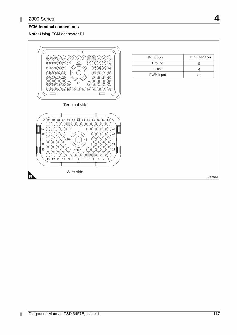
4
Diagnostic Manual, TSD 3457E, Issue 1 117
2300 Series
ECM terminal connections
Note: Using ECM connector P1.
B
1234568910111213
14
24
40
48
23
31
47
57
36
>PEI<
5859606162636566676870
13
64
51525354555657
40414243
32333435
24252627
44454647
36373839
28293031
14151617181920212223
123456789101112
69
5859606162636566676870 6469
7
Terminal side
Wire side
484950
Ground
+ 8V
PWM input
5
4
66
Function Pin Location
HA0024
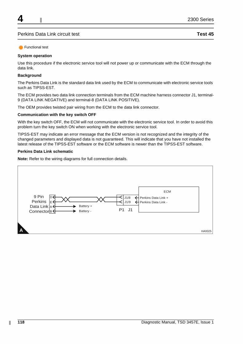
4
118 Diagnostic Manual, TSD 3457E, Issue 1
2300 Series
Perkins Data Link circuit test Test 45
System operation
Use this procedure if the electronic service tool will not power up or communicate with the ECM through the data link.
Background
The Perkins Data Link is the standard data link used by the ECM to communicate with electronic service tools such as TIPSS-EST.
The ECM provides two data link connection terminals from the ECM machine harness connector J1, terminal-9 (DATA LINK NEGATIVE) and terminal-8 (DATA LINK POSITIVE).
The OEM provides twisted pair wiring from the ECM to the data link connector.
Communication with the key switch OFF
With the key switch OFF, the ECM will not communicate with the electronic service tool. In order to avoid this problem turn the key switch ON when working with the electronic service tool.
TIPSS-EST may indicate an error message that the ECM version is not recognized and the integrity of the changed parameters and displayed data is not guaranteed. This will indicate that you have not installed the latest release of the TIPSS-EST software or the ECM software is newer than the TIPSS-EST software.
Perkins Data Link schematic
Note: Refer to the wiring diagrams for full connection details.
Functional test
A
ECM
J1/8J1/9 Perkins Data Link -
D Perkins Data Link +
E
A
B
Battery +
Battery - P1 J1
9 PinPerkins
Data LinkConnector
HA0025
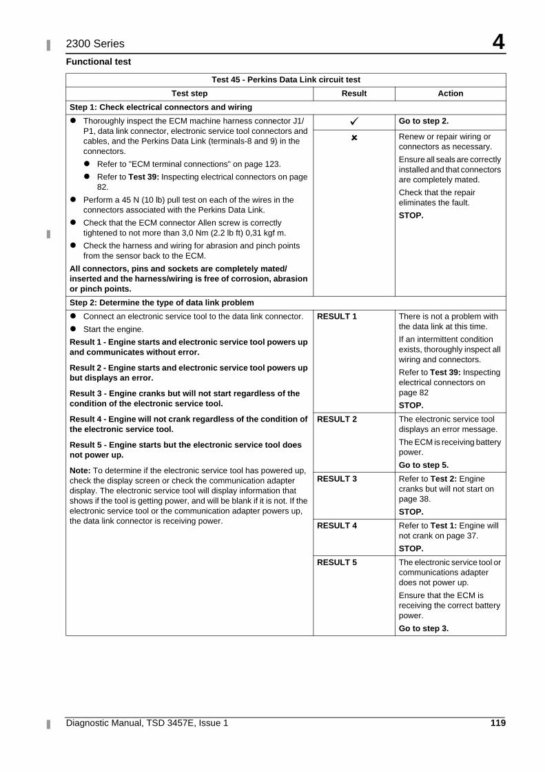
4
Diagnostic Manual, TSD 3457E, Issue 1 119
2300 Series
Functional test
Test 45 - Perkins Data Link circuit test
Test step Result Action
Step 1: Check electrical connectors and wiring
� Thoroughly inspect the ECM machine harness connector J1/P1, data link connector, electronic service tool connectors and cables, and the Perkins Data Link (terminals-8 and 9) in the connectors.
� Refer to "ECM terminal connections" on page 123.
� Refer to Test 39: Inspecting electrical connectors on page 82.
� Perform a 45 N (10 lb) pull test on each of the wires in the connectors associated with the Perkins Data Link.
� Check that the ECM connector Allen screw is correctly tightened to not more than 3,0 Nm (2.2 lb ft) 0,31 kgf m.
� Check the harness and wiring for abrasion and pinch points from the sensor back to the ECM.
All connectors, pins and sockets are completely mated/inserted and the harness/wiring is free of corrosion, abrasion or pinch points.
� Go to step 2.
� Renew or repair wiring or connectors as necessary.
Ensure all seals are correctly installed and that connectors are completely mated.
Check that the repair eliminates the fault.
STOP.
Step 2: Determine the type of data link problem
� Connect an electronic service tool to the data link connector.
� Start the engine.
Result 1 - Engine starts and electronic service tool powers up and communicates without error.
Result 2 - Engine starts and electronic service tool powers up but displays an error.
Result 3 - Engine cranks but will not start regardless of the condition of the electronic service tool.
Result 4 - Engine will not crank regardless of the condition of the electronic service tool.
Result 5 - Engine starts but the electronic service tool does not power up.
Note: To determine if the electronic service tool has powered up, check the display screen or check the communication adapter display. The electronic service tool will display information that shows if the tool is getting power, and will be blank if it is not. If the electronic service tool or the communication adapter powers up, the data link connector is receiving power.
RESULT 1 There is not a problem with the data link at this time.
If an intermittent condition exists, thoroughly inspect all wiring and connectors.
Refer to Test 39: Inspecting electrical connectors on page 82
STOP.
RESULT 2 The electronic service tool displays an error message.
The ECM is receiving battery power.
Go to step 5.
RESULT 3 Refer to Test 2: Engine cranks but will not start on page 38.
STOP.
RESULT 4 Refer to Test 1: Engine will not crank on page 37.
STOP.
RESULT 5 The electronic service tool or communications adapter does not power up.
Ensure that the ECM is receiving the correct battery power.
Go to step 3.
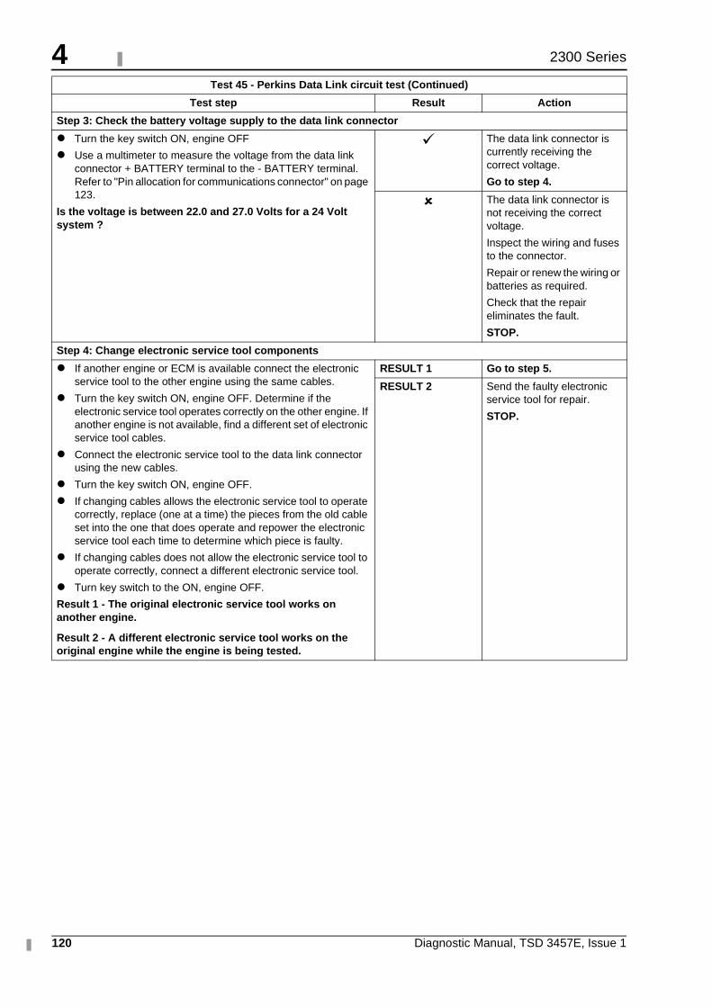
4
120 Diagnostic Manual, TSD 3457E, Issue 1
2300 Series
Step 3: Check the battery voltage supply to the data link connector
� Turn the key switch ON, engine OFF
� Use a multimeter to measure the voltage from the data link connector + BATTERY terminal to the - BATTERY terminal. Refer to "Pin allocation for communications connector" on page 123.
Is the voltage is between 22.0 and 27.0 Volts for a 24 Volt system ?
� The data link connector is currently receiving the correct voltage.
Go to step 4.
� The data link connector is not receiving the correct voltage.
Inspect the wiring and fuses to the connector.
Repair or renew the wiring or batteries as required.
Check that the repair eliminates the fault.
STOP.
Step 4: Change electronic service tool components
� If another engine or ECM is available connect the electronic service tool to the other engine using the same cables.
� Turn the key switch ON, engine OFF. Determine if the electronic service tool operates correctly on the other engine. If another engine is not available, find a different set of electronic service tool cables.
� Connect the electronic service tool to the data link connector using the new cables.
� Turn the key switch ON, engine OFF.
� If changing cables allows the electronic service tool to operate correctly, replace (one at a time) the pieces from the old cable set into the one that does operate and repower the electronic service tool each time to determine which piece is faulty.
� If changing cables does not allow the electronic service tool to operate correctly, connect a different electronic service tool.
� Turn key switch to the ON, engine OFF.
Result 1 - The original electronic service tool works on another engine.
Result 2 - A different electronic service tool works on the original engine while the engine is being tested.
RESULT 1 Go to step 5.
RESULT 2 Send the faulty electronic service tool for repair.
STOP.
Test 45 - Perkins Data Link circuit test (Continued)
Test step Result Action
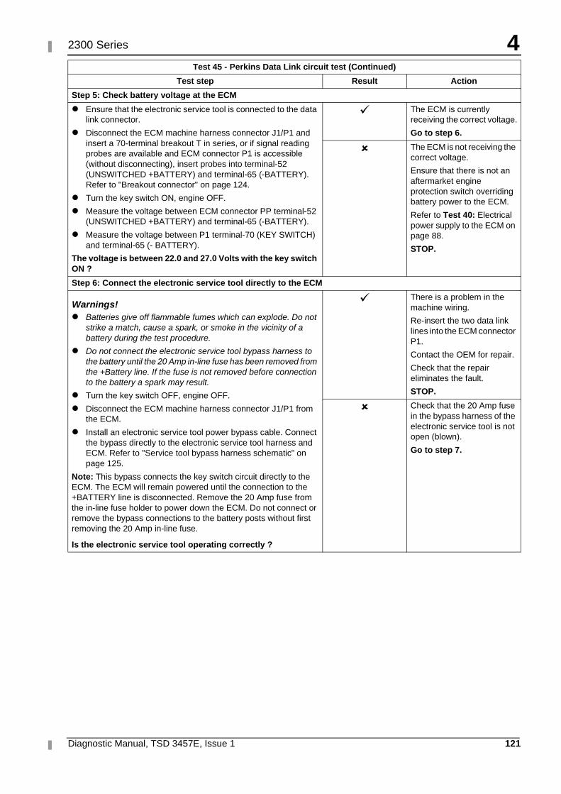
4
Diagnostic Manual, TSD 3457E, Issue 1 121
2300 Series
Step 5: Check battery voltage at the ECM
� Ensure that the electronic service tool is connected to the data link connector.
� Disconnect the ECM machine harness connector J1/P1 and insert a 70-terminal breakout T in series, or if signal reading probes are available and ECM connector P1 is accessible (without disconnecting), insert probes into terminal-52 (UNSWITCHED +BATTERY) and terminal-65 (-BATTERY). Refer to "Breakout connector" on page 124.
� Turn the key switch ON, engine OFF.
� Measure the voltage between ECM connector PP terminal-52 (UNSWITCHED +BATTERY) and terminal-65 (-BATTERY).
� Measure the voltage between P1 terminal-70 (KEY SWITCH) and terminal-65 (- BATTERY).
The voltage is between 22.0 and 27.0 Volts with the key switch ON ?
� The ECM is currently receiving the correct voltage.
Go to step 6.
� The ECM is not receiving the correct voltage.
Ensure that there is not an aftermarket engine protection switch overriding battery power to the ECM.
Refer to Test 40: Electrical power supply to the ECM on page 88.
STOP.
Step 6: Connect the electronic service tool directly to the ECM
Warnings!� Batteries give off flammable fumes which can explode. Do not
strike a match, cause a spark, or smoke in the vicinity of a battery during the test procedure.
� Do not connect the electronic service tool bypass harness to the battery until the 20 Amp in-line fuse has been removed from the +Battery line. If the fuse is not removed before connection to the battery a spark may result.
� Turn the key switch OFF, engine OFF.
� Disconnect the ECM machine harness connector J1/P1 from the ECM.
� Install an electronic service tool power bypass cable. Connect the bypass directly to the electronic service tool harness and ECM. Refer to "Service tool bypass harness schematic" on page 125.
Note: This bypass connects the key switch circuit directly to the ECM. The ECM will remain powered until the connection to the +BATTERY line is disconnected. Remove the 20 Amp fuse from the in-line fuse holder to power down the ECM. Do not connect or remove the bypass connections to the battery posts without first removing the 20 Amp in-line fuse.
Is the electronic service tool operating correctly ?
� There is a problem in the machine wiring.
Re-insert the two data link lines into the ECM connector P1.
Contact the OEM for repair.
Check that the repair eliminates the fault.
STOP.
� Check that the 20 Amp fuse in the bypass harness of the electronic service tool is not open (blown).
Go to step 7.
Test 45 - Perkins Data Link circuit test (Continued)
Test step Result Action
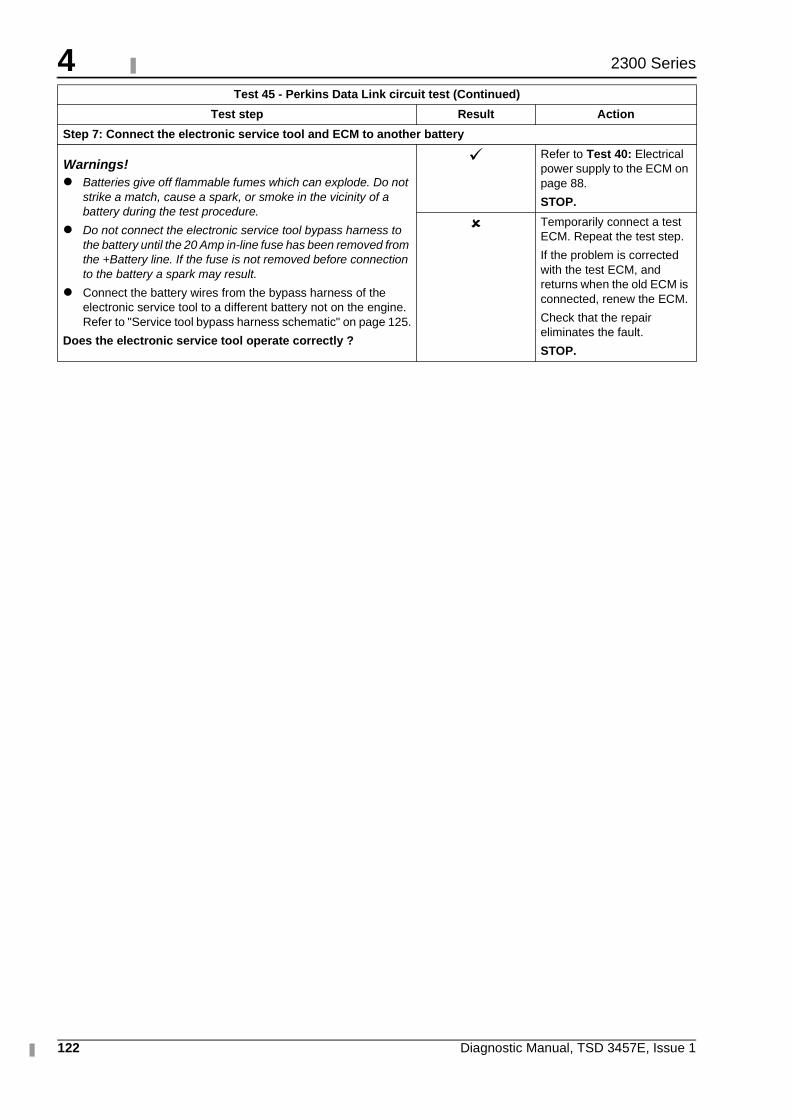
4
122 Diagnostic Manual, TSD 3457E, Issue 1
2300 Series
Step 7: Connect the electronic service tool and ECM to another battery
Warnings!� Batteries give off flammable fumes which can explode. Do not
strike a match, cause a spark, or smoke in the vicinity of a battery during the test procedure.
� Do not connect the electronic service tool bypass harness to the battery until the 20 Amp in-line fuse has been removed from the +Battery line. If the fuse is not removed before connection to the battery a spark may result.
� Connect the battery wires from the bypass harness of the electronic service tool to a different battery not on the engine. Refer to "Service tool bypass harness schematic" on page 125.
Does the electronic service tool operate correctly ?
� Refer to Test 40: Electrical power supply to the ECM on page 88.
STOP.
� Temporarily connect a test ECM. Repeat the test step.
If the problem is corrected with the test ECM, and returns when the old ECM is connected, renew the ECM.
Check that the repair eliminates the fault.
STOP.
Test 45 - Perkins Data Link circuit test (Continued)
Test step Result Action
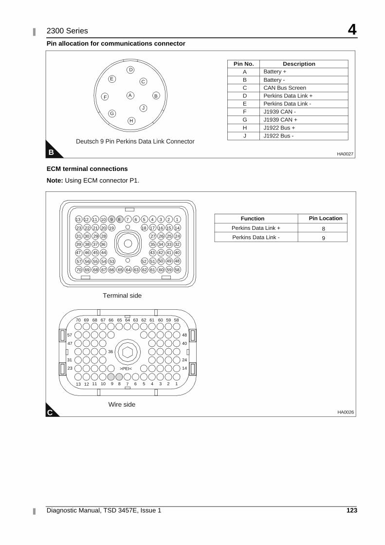
4
Diagnostic Manual, TSD 3457E, Issue 1 123
2300 Series
Pin allocation for communications connector
ECM terminal connections
Note: Using ECM connector P1.
B
Deutsch 9 Pin Perkins Data Link Connector
Pin No. DescriptionABCDEFGHJ
Battery +
Battery -
Perkins Data Link -Perkins Data Link +CAN Bus Screen
J1939 CAN -J1939 CAN +J1922 Bus +J1922 Bus -
D
C
BA
E
F
G
H
J
HA0027
C
1234568910111213
14
24
40
48
23
31
47
57
36
>PEI<
5859606162636566676870
13
64
51525354555657
40414243
32333435
24252627
44454647
36373839
28293031
14151617181920212223
123456789101112
69
5859606162636566676870 6469
7
Terminal side
Wire side
484950
Perkins Data Link +
Perkins Data Link -
8
9
Function Pin Location
HA0026
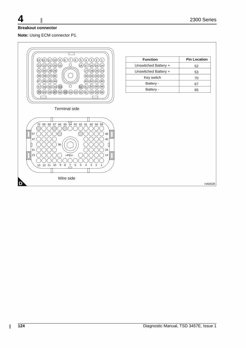
4
124 Diagnostic Manual, TSD 3457E, Issue 1
2300 Series
Breakout connector
Note: Using ECM connector P1.
D
1234568910111213
14
24
40
48
23
31
47
57
36
>PEI<
5859606162636566676870
13
64
51525354555657
40414243
32333435
24252627
44454647
36373839
28293031
14151617181920212223
123456789101112
69
5859606162636566676870 6469
7
Terminal side
Wire side
484950
Unswitched Battery +
Unswitched Battery +
Key switch
Battery -
Battery -
52
53
70
67
65
Function Pin Location
HA0028
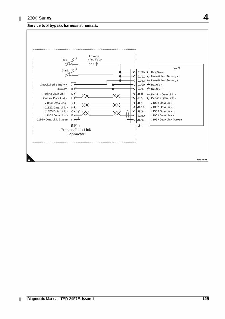
4
Diagnostic Manual, TSD 3457E, Issue 1 125
2300 Series
Service tool bypass harness schematic
E
ECM
J1/8J1/9 Perkins Data Link -
D Perkins Data Link +E
A
B
J19 PinPerkins Data Link
Connector
20 AmpIn line FuseRed
BlackJ1/70
J1/52
J1/53J1/65
J1/67
Key Switch
Unswitched Battery +
Unswitched Battery +
Battery -
Battery -
J1/1J1/14
J1/34
J1/50
J1/42
J1922 Data Link -
J1922 Data Link +
J1939 Data Link +
J1939 Data Link -
J1939 Data Link Screen
J
HG
F
C
Unswitched Battery +
Battery -
Perkins Data Link +
Perkins Data Link -
J1922 Data Link -
J1922 Data Link +J1939 Data Link +
J1939 Data Link -
J1939 Data Link Screen
HA0029
4
126 Diagnostic Manual, TSD 3457E, Issue 1
2300 Series
Engine speed/timing circuit test Test 46
System operation
Use this procedure to diagnose the system only when there is an active or easily repeated diagnostic code that is associated with either the crankshaft or camshaft position sensor circuit or if you have been referred to this test from a diagnostic procedure without a diagnostic fault code.
The engine uses two engine speed/timing sensors. One sensor picks up the camshaft gear and the other the crankshaft gear. Both detect engine speed and timing reference from a unique pattern on the gear. The ECM counts the time between pulses created by the sensor as the gear rotates in order to determine rev/min.
Under normal operation, the camshaft position sensor is used to determine timing (when the piston in cylinder number 1 is at the top of the compression stroke) for starting purposes. When the timing has been established, the crankshaft position sensor is then used to determine engine speed and the camshaft position sensor signal is ignored.
After locating No. 1 cylinder, the ECM triggers each injector in the correct firing order and at the correct time. The actual timing and duration of each injection is based on engine rev/min and load. If the engine is running and the signal from the crankshaft position sensor is lost, a slight change in engine performance will be noticed when the ECM switches to the camshaft position sensor.
Loss of the camshaft position sensor signal during engine operation will not result in any noticeable change in engine performance. However, if the camshaft position sensor signal is not present during start-up the engine may take slightly longer to start, or may run rough for a few seconds until the ECM determines the correct firing order by using the crankshaft position sensor only.
The engine will start and run when only one sensor signal is present from either of the sensors. The loss of the signal from both sensors will result in the ECM terminating injection and shutting down the engine, or preventing it from starting.
Both sensors are magnetic with a connector on a "flying lead’.
Caution: The two sensors are not interchangeable, do not switch sensor positions.
If the sensors are replaced a timing calibration is NOT necessary for the engine.
Note: Timing calibration is only necessary after replacing an ECM that will not communicate.
If the ECM is replaced, it will be necessary to do a Timing Calibration.
The crankshaft position sensor is connected to the ECM through the engine harness connector J2/P2 terminal-48 (CRANK SPEED/TIMING POSITIVE) and terminal-49 (CRANK SPEED/TIMING NEGATIVE).
The camshaft position sensor is connected to the ECM through engine harness connector J2/P2 terminal-58 (CAM SPEED/TIMING POSITIVE) and terminal-59 (CAM SPEED/TIMING NEGATIVE).
Diagnostic codes Functional test
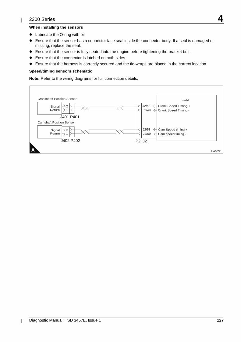
4
Diagnostic Manual, TSD 3457E, Issue 1 127
2300 Series
When installing the sensors
� Lubricate the O-ring with oil.
� Ensure that the sensor has a connector face seal inside the connector body. If a seal is damaged or missing, replace the seal.
� Ensure that the sensor is fully seated into the engine before tightening the bracket bolt.
� Ensure that the connector is latched on both sides.
� Ensure that the harness is correctly secured and the tie-wraps are placed in the correct location.
Speed/timing sensors schematic
Note: Refer to the wiring diagrams for full connection details.
A
ECM
J2/48J2/49 Crank Speed Timing -
2Signal1Return
Crankshaft Position Sensor
Crank Speed Timing +
J2/58J2/59 Cam speed timing -
2Signal1Return
Camshaft Position Sensor
Cam Speed timing +
J401 P401
J402 P402 P2 J2
HA0030
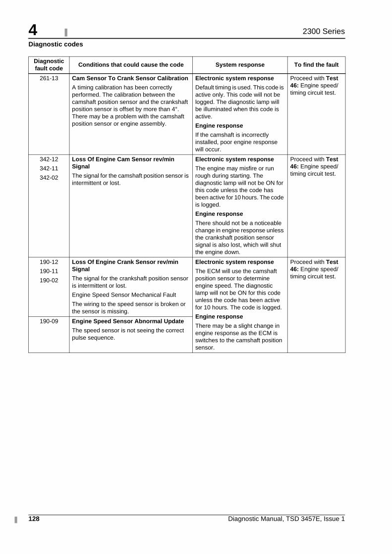
4
128 Diagnostic Manual, TSD 3457E, Issue 1
2300 Series
Diagnostic codes
Diagnostic fault code
Conditions that could cause the code System response To find the fault
261-13 Cam Sensor To Crank Sensor Calibration
A timing calibration has been correctly performed. The calibration between the camshaft position sensor and the crankshaft position sensor is offset by more than 4°. There may be a problem with the camshaft position sensor or engine assembly.
Electronic system response
Default timing is used. This code is active only. This code will not be logged. The diagnostic lamp will be illuminated when this code is active.
Engine response
If the camshaft is incorrectly installed, poor engine response will occur.
Proceed with Test 46: Engine speed/timing circuit test.
342-12
342-11
342-02
Loss Of Engine Cam Sensor rev/min Signal
The signal for the camshaft position sensor is intermittent or lost.
Electronic system response
The engine may misfire or run rough during starting. The diagnostic lamp will not be ON for this code unless the code has been active for 10 hours. The code is logged.
Engine response
There should not be a noticeable change in engine response unless the crankshaft position sensor signal is also lost, which will shut the engine down.
Proceed with Test 46: Engine speed/timing circuit test.
190-12
190-11
190-02
Loss Of Engine Crank Sensor rev/min Signal
The signal for the crankshaft position sensor is intermittent or lost.
Engine Speed Sensor Mechanical Fault
The wiring to the speed sensor is broken or the sensor is missing.
Electronic system response
The ECM will use the camshaft position sensor to determine engine speed. The diagnostic lamp will not be ON for this code unless the code has been active for 10 hours. The code is logged.
Engine response
There may be a slight change in engine response as the ECM is switches to the camshaft position sensor.
Proceed with Test 46: Engine speed/timing circuit test.
190-09 Engine Speed Sensor Abnormal Update
The speed sensor is not seeing the correct pulse sequence.
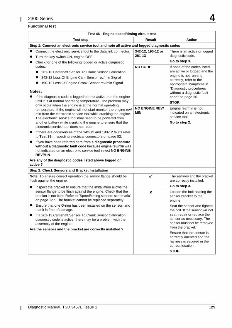
4
Diagnostic Manual, TSD 3457E, Issue 1 129
2300 Series
Functional test
Test 46 - Engine speed/timing circuit test
Test step Result Action
Step 1: Connect an electronic service tool and note all active and logged diagnostic codes
� Connect the electronic service tool to the data link connector.
� Turn the key switch ON, engine OFF.
� Check for one of the following logged or active diagnostic codes:
� 261-13 Camshaft Sensor To Crank Sensor Calibration
� 342-12 Loss Of Engine Cam Sensor rev/min Signal
� 190-12 Loss Of Engine Crank Sensor rev/min Signal
Notes:� If the diagnostic code is logged but not active, run the engine
until it is at normal operating temperature. The problem may only occur when the engine is at the normal operating temperature. If the engine will not start monitor the engine rev/min from the electronic service tool while cranking the engine. The electronic service tool may need to be powered from another battery while cranking the engine to ensure that the electronic service tool does not reset.
� If there are occurrences of the 342-12 and 190-12 faults refer to Test 39: Inspecting electrical connectors on page 82.
� If you have been referred here from a diagnostic procedure without a diagnostic fault code because engine rev/min was not indicated on an electronic service tool select NO ENGINE REV/MIN.
Are any of the diagnostic codes listed above logged or active ?
342-12, 190-12 or 261-13
There is an active or logged diagnostic code.
Go to step 3.
NO CODE If none of the codes listed are active or logged and the engine is not running correctly, refer to the appropriate symptoms in "Diagnostic procedures without a diagnostic fault code" on page 36.
STOP.
NO ENGINE REV/MIN
Engine rev/min is not indicated on an electronic service tool.
Go to step 2.
Step 2: Check Sensors and Bracket Installation
Note: To ensure correct operation the sensor flange should be flush against the engine.
� Inspect the bracket to ensure that the installation allows the sensor flange to be flush against the engine. Check that the bracket is not bent. Refer to "Speed/timing sensors schematic" on page 127. The bracket cannot be replaced separately.
� Ensure that one O-ring has been installed on the sensor, and that it is free of damage.
� If a 261-13 Camshaft Sensor To Crank Sensor Calibration diagnostic code is active, there may be a problem with the assembly of the engine.
Are the sensors and the bracket are correctly installed ?
� The sensors and the bracket are correctly installed.
Go to step 3.
� Loosen the bolt holding the sensor bracket to the engine.
Seat the sensor and tighten the bolt. If the sensor will not seat, repair or replace the sensor as necessary. The sensor must not be removed from the bracket.
Ensure that the sensor is correctly oriented and the harness is secured in the correct location.
STOP.
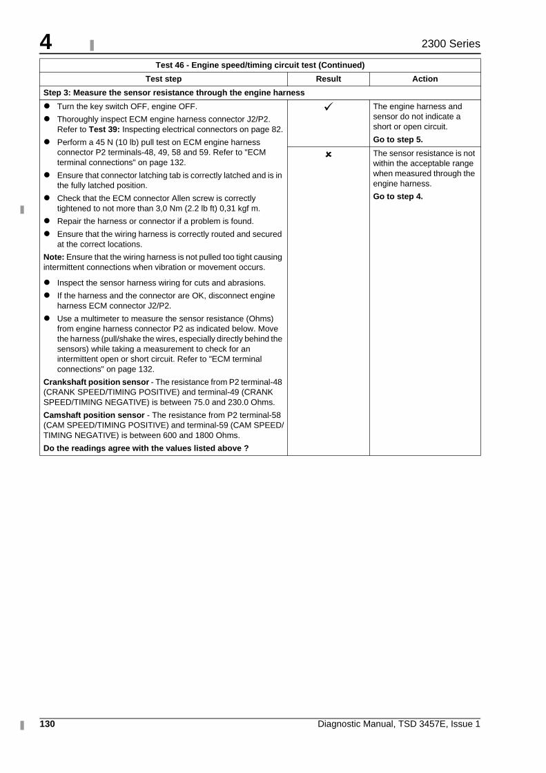
4
130 Diagnostic Manual, TSD 3457E, Issue 1
2300 Series
Step 3: Measure the sensor resistance through the engine harness
� Turn the key switch OFF, engine OFF.
� Thoroughly inspect ECM engine harness connector J2/P2. Refer to Test 39: Inspecting electrical connectors on page 82.
� Perform a 45 N (10 lb) pull test on ECM engine harness connector P2 terminals-48, 49, 58 and 59. Refer to "ECM terminal connections" on page 132.
� Ensure that connector latching tab is correctly latched and is in the fully latched position.
� Check that the ECM connector Allen screw is correctly tightened to not more than 3,0 Nm (2.2 lb ft) 0,31 kgf m.
� Repair the harness or connector if a problem is found.
� Ensure that the wiring harness is correctly routed and secured at the correct locations.
Note: Ensure that the wiring harness is not pulled too tight causing intermittent connections when vibration or movement occurs.
� Inspect the sensor harness wiring for cuts and abrasions.
� If the harness and the connector are OK, disconnect engine harness ECM connector J2/P2.
� Use a multimeter to measure the sensor resistance (Ohms) from engine harness connector P2 as indicated below. Move the harness (pull/shake the wires, especially directly behind the sensors) while taking a measurement to check for an intermittent open or short circuit. Refer to "ECM terminal connections" on page 132.
Crankshaft position sensor - The resistance from P2 terminal-48 (CRANK SPEED/TIMING POSITIVE) and terminal-49 (CRANK SPEED/TIMING NEGATIVE) is between 75.0 and 230.0 Ohms.
Camshaft position sensor - The resistance from P2 terminal-58 (CAM SPEED/TIMING POSITIVE) and terminal-59 (CAM SPEED/TIMING NEGATIVE) is between 600 and 1800 Ohms.
Do the readings agree with the values listed above ?
� The engine harness and sensor do not indicate a short or open circuit.
Go to step 5.
� The sensor resistance is not within the acceptable range when measured through the engine harness.
Go to step 4.
Test 46 - Engine speed/timing circuit test (Continued)
Test step Result Action
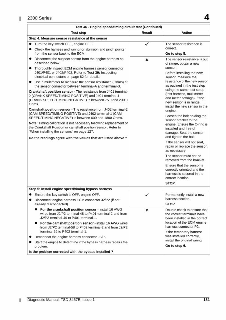
4
Diagnostic Manual, TSD 3457E, Issue 1 131
2300 Series
Step 4: Measure sensor resistance at the sensor
� Turn the key switch OFF, engine OFF.
� Check the harness and wiring for abrasion and pinch points from the sensor back to the ECM.
� Disconnect the suspect sensor from the engine harness as described below.
� Thoroughly inspect ECM engine harness sensor connector J401/P401 or J402/P402. Refer to Test 39: Inspecting electrical connectors on page 82 for details.
� Use a multimeter to measure the sensor resistance (Ohms) at the sensor connector between terminal-A and terminal-B.
Crankshaft position sensor - The resistance from J401 terminal-2 (CRANK SPEED/TIMING POSITIVE) and J401 terminal-1 (CRANK SPEED/TIMING NEGATIVE) is between 75.0 and 230.0 Ohms.
Camshaft position sensor - The resistance from J402 terminal-2 (CAM SPEED/TIMING POSITIVE) and J402 terminal-1 (CAM SPEED/TIMING NEGATIVE) is between 600 and 1800 Ohms.
Note: Timing calibration is not necessary following replacement of the Crankshaft Position or camshaft position sensor. Refer to "When installing the sensors" on page 127.
Do the readings agree with the values that are listed above ?
� The sensor resistance is correct.
Go to step 5.
� The sensor resistance is out of range, obtain a new sensor.
Before installing the new sensor, measure the resistance of the new sensor as outlined in the test step using the same test setup (test harness, multimeter and meter settings). If the new sensor is in range, install the new sensor in the engine.
Loosen the bolt holding the sensor bracket to the engine. Ensure the O-ring is installed and free of damage. Seat the sensor and tighten the bolt.
If the sensor will not seat, repair or replace the sensor, as necessary.
The sensor must not be removed from the bracket.
Ensure that the sensor is correctly oriented and the harness is secured in the correct location.
STOP.
Step 5: Install engine speed/timing bypass harness
� Ensure the key switch is OFF, engine OFF.
� Disconnect engine harness ECM connector J2/P2 (if not already disconnected).
� For the crankshaft position sensor - install 16 AWG wires from J2/P2 terminal-48 to P401 terminal-2 and from J2/P2 terminal-49 to P401 terminal-1.
� For the camshaft position sensor - install 16 AWG wires from J2/P2 terminal-58 to P402 terminal-2 and from J2/P2 terminal-59 to P402 terminal-1.
� Reconnect the engine harness connector J2/P2.
� Start the engine to determine if the bypass harness repairs the problem.
Is the problem corrected with the bypass installed ?
� Permanently install a new harness section.
STOP.
� Double check to ensure that the correct terminals have been installed in the correct location of the ECM engine harness connector P2.
If the temporary harness was installed correctly, install the original wiring.
Go to step 6.
Test 46 - Engine speed/timing circuit test (Continued)
Test step Result Action
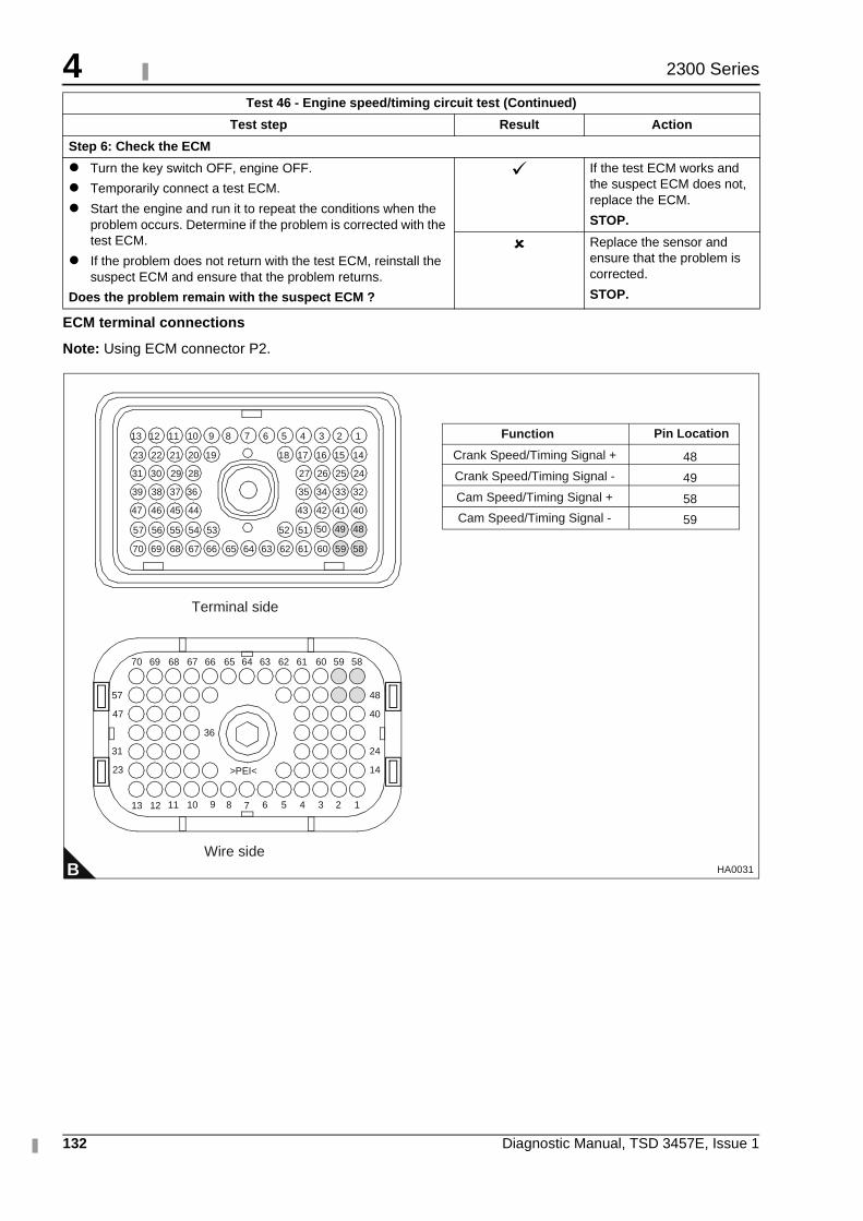
4
132 Diagnostic Manual, TSD 3457E, Issue 1
2300 Series
ECM terminal connections
Note: Using ECM connector P2.
Step 6: Check the ECM
� Turn the key switch OFF, engine OFF.
� Temporarily connect a test ECM.
� Start the engine and run it to repeat the conditions when the problem occurs. Determine if the problem is corrected with the test ECM.
� If the problem does not return with the test ECM, reinstall the suspect ECM and ensure that the problem returns.
Does the problem remain with the suspect ECM ?
� If the test ECM works and the suspect ECM does not, replace the ECM.
STOP.
� Replace the sensor and ensure that the problem is corrected.
STOP.
Test 46 - Engine speed/timing circuit test (Continued)
Test step Result Action
B
1234568910111213
14
24
40
48
23
31
47
57
36
>PEI<
5859606162636566676870
13
64
51525354555657
40414243
32333435
24252627
44454647
36373839
28293031
14151617181920212223
123456789101112
69
5859606162636566676870 6469
7
Terminal side
Wire side
484950
Crank Speed/Timing Signal +
Crank Speed/Timing Signal -
Cam Speed/Timing Signal +
Cam Speed/Timing Signal -
48
49
58
59
Function Pin Location
HA0031
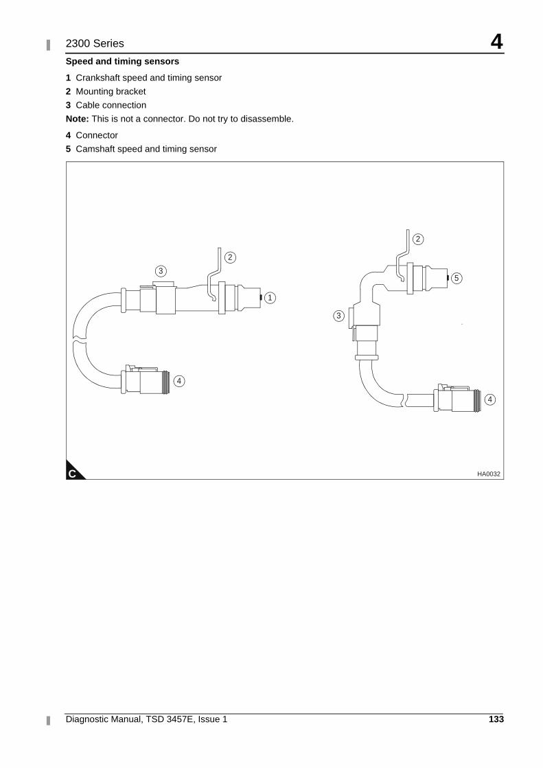
4
Diagnostic Manual, TSD 3457E, Issue 1 133
2300 Series
Speed and timing sensors
1 Crankshaft speed and timing sensor
2 Mounting bracket
3 Cable connection
Note: This is not a connector. Do not try to disassemble.
4 Connector
5 Camshaft speed and timing sensor
C HA0032
1
2
3
4
3
5
2
4
4
134 Diagnostic Manual, TSD 3457E, Issue 1
2300 Series
Engine speed/timing calibration Test 47
Special tools
System operation
Use this procedure if diagnostic code 261-13 Check Timing Sensor Calibration is present, if the ECM has been replaced or if work has been done to the engine front drive train.
The crankshaft position sensor provides an engine speed signal (rev/min) to the ECM. The signal is created as the crankshaft gear rotates past the pickup of the crankshaft position sensor. The camshaft position sensor provides the timing signal to the ECM. The signal is created as the camshaft gear rotates past the pickup of the camshaft position sensor. A unique pattern on the gear allows the ECM to determine the crankshaft position and when the cylinder number one piston is at the top of the compression stroke. In the event that the signal is lost from one of the sensors, a diagnostic code is generated. The ECM then uses special logic to allow the engine to start and run on only one sensor.
If the ECM requires replacement or if work has been performed on the front drive train, a timing calibration must be performed.
Timing calibration is accomplished by installing a special magnetic pickup into the side of the engine block. The magnetic pickup senses a special slot on the crankshaft counterweight. The magnetic pickup is then connected to the ECM through the engine harness speed/timing calibration connector P400, while the engine is running.
In order to carry out a timing calibration, the engine must be running at 1100 rev/min. Since this speed is not within the range of the normal speed setting controls, proceed as follows:
1 Set the "Digital Speed Control Installed" to "Not Installed" from the TIPSS-EST configuration screen.
2 If an analogue speed control is fitted, select PWM speed control in the "Desired Speed Input Arrangement" option on the configuration screen. If a PWM speed control is fitted, select Analogue speed control in the "Desired Speed Input Arrangement" on the configuration screen.
Note: If both analogue and PWM speed inputs are connected, one must be disconnected and the associated speed control selected.
3 If the engine is now run, it should run up to 1100 rev/min and timing calibration can be carried out.
4 After completion of the timing calibration, ensure that all parameters are returned to their original values.
Note: Timing calibration will not increase or decrease the available engine power. Do not calibrate the engine timing expecting an increase in engine power.
Diagnostic codes Functional test
Part Number Description
GE50038 Timing calibration probe
GE50040 Harness adapter for deutsch “DT” timing probe connection
GE50039 Timing calibration probe adapter sleeve
CH11148 Engine turning tool
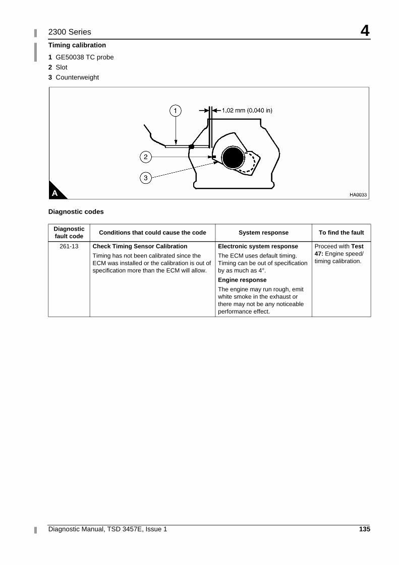
4
Diagnostic Manual, TSD 3457E, Issue 1 135
2300 Series
Timing calibration
1 GE50038 TC probe
2 Slot
3 Counterweight
Diagnostic codes
Diagnostic fault code
Conditions that could cause the code System response To find the fault
261-13 Check Timing Sensor Calibration
Timing has not been calibrated since the ECM was installed or the calibration is out of specification more than the ECM will allow.
Electronic system response
The ECM uses default timing. Timing can be out of specification by as much as 4°.
Engine response
The engine may run rough, emit white smoke in the exhaust or there may not be any noticeable performance effect.
Proceed with Test 47: Engine speed/timing calibration.
4
136 Diagnostic Manual, TSD 3457E, Issue 1
2300 Series
Functional test
Test 47 - Engine speed/timing calibration
Test step Result Action
Step 1: Install the timing adapter group
� Turn the key switch OFF, engine OFF
� Use the turning tool to put either the No. 1 or No. 6 piston at top centre. After locating top centre, rotate the engine back (rotate the engine in opposite direction of correct engine rotation) 60°.
� Remove the timing calibration plug from the left side of the engine and install the timing probe adapter sleeve into the hole for the plug.
� Go to step 2.
Step 2: Install GE50038 TC probe on the engine
Caution: If the crankshaft is not in the correct position when the timing probe is installed, the timing probe will be damaged when the engine is started.
� Put a 2D-6392 O-ring on the end of the magnetic pickup sensor (a small amount of clean engine oil will allow the seal to slide onto the sensor more easily).
� Push the sensor through the adapter until it comes in contact with the outermost portion of the crankshaft counterweight. Move the O-ring downward against the adapter.
� Withdraw the magnetic transducer 1,0 mm (0.04 in) and hand tighten the nut on the adapter sleeve in order to secure the magnetic pickup in place.
� Connect the GE50038 timing probe to the GE50040 Deutsch DT timing harness adapter.
� Go to step 3.
Step 3: Start engine and allow coolant to reach operating temperature
� Start the engine and run until the engine has warmed up enough to exit cold mode operation. The electronic service tool "Status" screen will display “COLD MODE” in the upper corner when cold mode operation exists.
� Check for ACTIVE diagnostic codes. Use the procedures in this manual to diagnose and repair any ACTIVE diagnostic codes before attempting a calibration check. The engine must not have any diagnostic fault conditions present during the timing calibration, other than 261-13 Check Timing Sensor Calibration.
� Stop the engine.
� Go to step 4.
Step 4: Connect an electronic service tool
� Connect an electronic service tool to the data link connector.
� Follow the procedure in "System operation" on page 134 so that the engine will run at 1100 rev/min.
� Access the "Timing Calibration" screen located under the "Service\Calibrations" menu on TIPSS-EST.
Note: To perform a timing calibration, the engine rev/min must be held as steady as possible at approximately 1100 rev/min. Any changes to engine rev/min (greater than 100 rev/min) will slow down the procedure and reduce accuracy. The correct engine speed is set using the procedure described "System operation" on page 134.
� Connect the GE50040 Deutsch DT adapter harness for the GE50038 timing probe to the speed/timing calibration connector P400.
� Be certain that all connections (TC Probe, electronic service tool, etc) are made correctly.
� Start the engine
� Go to step 5.
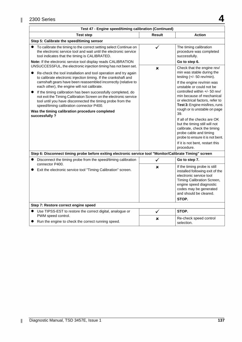
4
Diagnostic Manual, TSD 3457E, Issue 1 137
2300 Series
Step 5: Calibrate the speed/timing sensor
� To calibrate the timing to the correct setting select Continue on the electronic service tool and wait until the electronic service tool indicates that the timing is CALIBRATED.
Note: If the electronic service tool display reads CALIBRATION UNSUCCESSFUL, the electronic injection timing has not been set.
� Re-check the tool installation and tool operation and try again to calibrate electronic injection timing. If the crankshaft and camshaft gears have been reassembled incorrectly (relative to each other), the engine will not calibrate.
� If the timing calibration has been successfully completed, do not exit the Timing Calibration Screen on the electronic service tool until you have disconnected the timing probe from the speed/timing calibration connector P400.
Was the timing calibration procedure completed successfully ?
� The timing calibration procedure was completed successfully.
Go to step 6.
� Check that the engine rev/min was stable during the testing (+/- 50 rev/min).
If the engine rev/min was unstable or could not be controlled within +/- 50 rev/min because of mechanical or electrical factors, refer to Test 3: Engine misfires, runs rough or is unstable on page 39.
If all of the checks are OK but the timing still will not calibrate, check the timing probe cable and timing probe to ensure it is not bent.
If it is not bent, restart this procedure.
Step 6: Disconnect timing probe before exiting electronic service tool "Monitor/Calibrate Timing" screen
� Disconnect the timing probe from the speed/timing calibration connector P400.
� Exit the electronic service tool "Timing Calibration" screen.
� Go to step 7.
� If the timing probe is still installed following exit of the electronic service tool Timing Calibration Screen, engine speed diagnostic codes may be generated and should be cleared.
STOP.
Step 7: Restore correct engine speed
� Use TIPSS-EST to restore the correct digital, analogue or PWM speed control.
� Run the engine to check the correct running speed.
� STOP.
� Re-check speed control selection.
Test 47 - Engine speed/timing calibration (Continued)
Test step Result Action
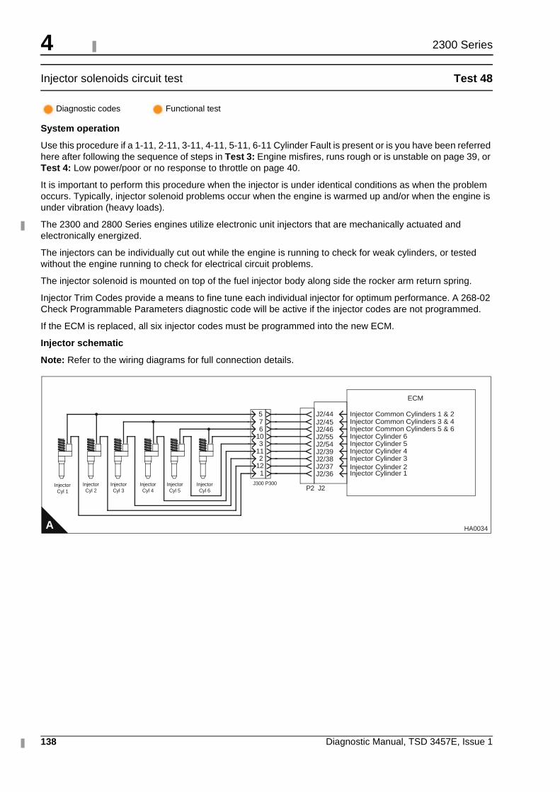
4
138 Diagnostic Manual, TSD 3457E, Issue 1
2300 Series
Injector solenoids circuit test Test 48
System operation
Use this procedure if a 1-11, 2-11, 3-11, 4-11, 5-11, 6-11 Cylinder Fault is present or is you have been referred here after following the sequence of steps in Test 3: Engine misfires, runs rough or is unstable on page 39, or Test 4: Low power/poor or no response to throttle on page 40.
It is important to perform this procedure when the injector is under identical conditions as when the problem occurs. Typically, injector solenoid problems occur when the engine is warmed up and/or when the engine is under vibration (heavy loads).
The 2300 and 2800 Series engines utilize electronic unit injectors that are mechanically actuated and electronically energized.
The injectors can be individually cut out while the engine is running to check for weak cylinders, or tested without the engine running to check for electrical circuit problems.
The injector solenoid is mounted on top of the fuel injector body along side the rocker arm return spring.
Injector Trim Codes provide a means to fine tune each individual injector for optimum performance. A 268-02 Check Programmable Parameters diagnostic code will be active if the injector codes are not programmed.
If the ECM is replaced, all six injector codes must be programmed into the new ECM.
Injector schematic
Note: Refer to the wiring diagrams for full connection details.
Diagnostic codes Functional test
A
ECM
J2/44 Injector Common Cylinders 1 & 2
P2 J2InjectorCyl 1
InjectorCyl 2
InjectorCyl 3
InjectorCyl 4
InjectorCyl 5
InjectorCyl 6
J2/45J2/46J2/55J2/54J2/39J2/38J2/37J2/36
Injector Common Cylinders 3 & 4Injector Common Cylinders 5 & 6Injector Cylinder 6Injector Cylinder 5Injector Cylinder 4Injector Cylinder 3Injector Cylinder 2Injector Cylinder 1
576
103
112
12 1
J300 P300
HA0034
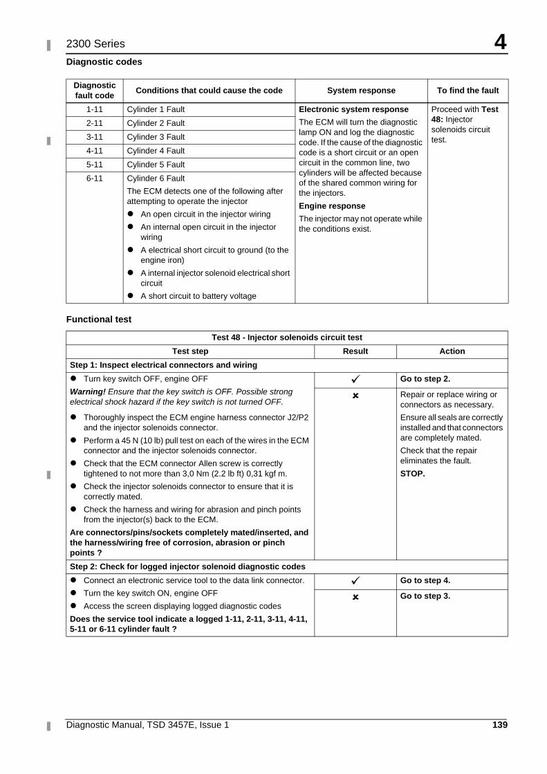
4
Diagnostic Manual, TSD 3457E, Issue 1 139
2300 Series
Diagnostic codes
Functional test
Diagnostic fault code
Conditions that could cause the code System response To find the fault
1-11 Cylinder 1 Fault Electronic system response
The ECM will turn the diagnostic lamp ON and log the diagnostic code. If the cause of the diagnostic code is a short circuit or an open circuit in the common line, two cylinders will be affected because of the shared common wiring for the injectors.
Engine response
The injector may not operate while the conditions exist.
Proceed with Test 48: Injector solenoids circuit test.
2-11 Cylinder 2 Fault
3-11 Cylinder 3 Fault
4-11 Cylinder 4 Fault
5-11 Cylinder 5 Fault
6-11 Cylinder 6 Fault
The ECM detects one of the following after attempting to operate the injector
� An open circuit in the injector wiring
� An internal open circuit in the injector wiring
� A electrical short circuit to ground (to the engine iron)
� A internal injector solenoid electrical short circuit
� A short circuit to battery voltage
Test 48 - Injector solenoids circuit test
Test step Result Action
Step 1: Inspect electrical connectors and wiring
� Turn key switch OFF, engine OFF
Warning! Ensure that the key switch is OFF. Possible strong electrical shock hazard if the key switch is not turned OFF.
� Thoroughly inspect the ECM engine harness connector J2/P2 and the injector solenoids connector.
� Perform a 45 N (10 lb) pull test on each of the wires in the ECM connector and the injector solenoids connector.
� Check that the ECM connector Allen screw is correctly tightened to not more than 3,0 Nm (2.2 lb ft) 0,31 kgf m.
� Check the injector solenoids connector to ensure that it is correctly mated.
� Check the harness and wiring for abrasion and pinch points from the injector(s) back to the ECM.
Are connectors/pins/sockets completely mated/inserted, and the harness/wiring free of corrosion, abrasion or pinch points ?
� Go to step 2.
� Repair or replace wiring or connectors as necessary.
Ensure all seals are correctly installed and that connectors are completely mated.
Check that the repair eliminates the fault.
STOP.
Step 2: Check for logged injector solenoid diagnostic codes
� Connect an electronic service tool to the data link connector.
� Turn the key switch ON, engine OFF
� Access the screen displaying logged diagnostic codes
Does the service tool indicate a logged 1-11, 2-11, 3-11, 4-11, 5-11 or 6-11 cylinder fault ?
� Go to step 4.
� Go to step 3.
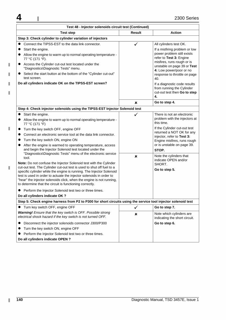
4
140 Diagnostic Manual, TSD 3457E, Issue 1
2300 Series
Step 3: Check cylinder to cylinder variation of injectors
� Connect the TIPSS-EST to the data link connector.
� Start the engine.
� Allow the engine to warm up to normal operating temperature - 77 °C (171 °F).
� Access the Cylinder cut-out test located under the "Diagnostics\Diagnostic Tests" menu.
� Select the start button at the bottom of the "Cylinder cut-out" test screen.
Do all cylinders indicate OK on the TIPSS-EST screen?
� All cylinders test OK.
If a misfiring problem or low power problem still exists refer to Test 3: Engine misfires, runs rough or is unstable on page 39 or Test 4: Low power/poor or no response to throttle on page 40.
If a diagnostic code results from running the Cylinder cut-out test then Go to step 4.
� Go to step 4.
Step 4: Check injector solenoids using the TIPSS-EST Injector Solenoid test
� Start the engine.
� Allow the engine to warm up to normal operating temperature - 77 °C (171 °F)
� Turn the key switch OFF, engine OFF
� Connect an electronic service tool at the data link connector.
� Turn the key switch ON, engine ON
� After the engine is warmed to operating temperature, access and begin the Injector Solenoid test located under the "Diagnostics\Diagnostic Tests" menu of the electronic service tool.
Note: Do not confuse the Injector Solenoid test with the Cylinder cut-out test. The Cylinder cut-out test is used to shut off fuel to a specific cylinder while the engine is running. The Injector Solenoid test is used in order to actuate the injector solenoids in order to "hear" the injector solenoids click, when the engine is not running, to determine that the circuit is functioning correctly.
� Perform the Injector Solenoid test two or three times.
Do all cylinders indicate OK ?
� There is not an electronic problem with the injectors at this time.
If the Cylinder cut-out test returned a NOT OK for any injector, refer to Test 3: Engine misfires, runs rough or is unstable on page 39.
STOP.
� Note the cylinders that indicate OPEN and/or SHORT.
Go to step 5.
Step 5: Check engine harness from P2 to P300 for short circuits using the service tool injector solenoid test
� Turn key switch OFF, engine OFF
Warning! Ensure that the key switch is OFF. Possible strong electrical shock hazard if the key switch is not turned OFF.
� Disconnect the injector solenoids connector J300/P300
� Turn the key switch ON, engine OFF
� Perform the Injector Solenoid test two or three times.
Do all cylinders indicate OPEN ?
� Go to step 7.
� Note which cylinders are indicating the short circuit.
Go to step 6.
Test 48 - Injector solenoids circuit test (Continued)
Test step Result Action
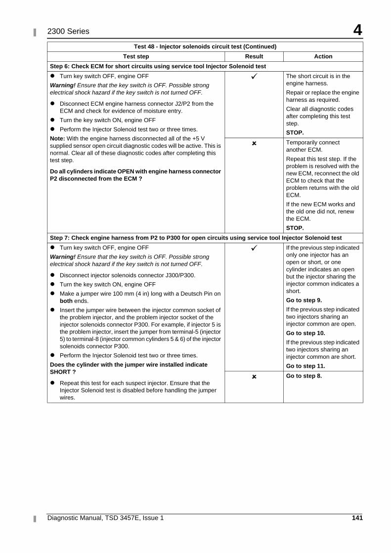
4
Diagnostic Manual, TSD 3457E, Issue 1 141
2300 Series
Step 6: Check ECM for short circuits using service tool Injector Solenoid test
� Turn key switch OFF, engine OFF
Warning! Ensure that the key switch is OFF. Possible strong electrical shock hazard if the key switch is not turned OFF.
� Disconnect ECM engine harness connector J2/P2 from the ECM and check for evidence of moisture entry.
� Turn the key switch ON, engine OFF
� Perform the Injector Solenoid test two or three times.
Note: With the engine harness disconnected all of the +5 V supplied sensor open circuit diagnostic codes will be active. This is normal. Clear all of these diagnostic codes after completing this test step.
Do all cylinders indicate OPEN with engine harness connector P2 disconnected from the ECM ?
� The short circuit is in the engine harness.
Repair or replace the engine harness as required.
Clear all diagnostic codes after completing this test step.
STOP.
� Temporarily connect another ECM.
Repeat this test step. If the problem is resolved with the new ECM, reconnect the old ECM to check that the problem returns with the old ECM.
If the new ECM works and the old one did not, renew the ECM.
STOP.
Step 7: Check engine harness from P2 to P300 for open circuits using service tool Injector Solenoid test
� Turn key switch OFF, engine OFF
Warning! Ensure that the key switch is OFF. Possible strong electrical shock hazard if the key switch is not turned OFF.
� Disconnect injector solenoids connector J300/P300.
� Turn the key switch ON, engine OFF
� Make a jumper wire 100 mm (4 in) long with a Deutsch Pin on both ends.
� Insert the jumper wire between the injector common socket of the problem injector, and the problem injector socket of the injector solenoids connector P300. For example, if injector 5 is the problem injector, insert the jumper from terminal-5 (injector 5) to terminal-8 (injector common cylinders 5 & 6) of the injector solenoids connector P300.
� Perform the Injector Solenoid test two or three times.
Does the cylinder with the jumper wire installed indicate SHORT ?
� Repeat this test for each suspect injector. Ensure that the Injector Solenoid test is disabled before handling the jumper wires.
� If the previous step indicated only one injector has an open or short, or one cylinder indicates an open but the injector sharing the injector common indicates a short.
Go to step 9.
If the previous step indicated two injectors sharing an injector common are open.
Go to step 10.
If the previous step indicated two injectors sharing an injector common are short.
Go to step 11.
� Go to step 8.
Test 48 - Injector solenoids circuit test (Continued)
Test step Result Action
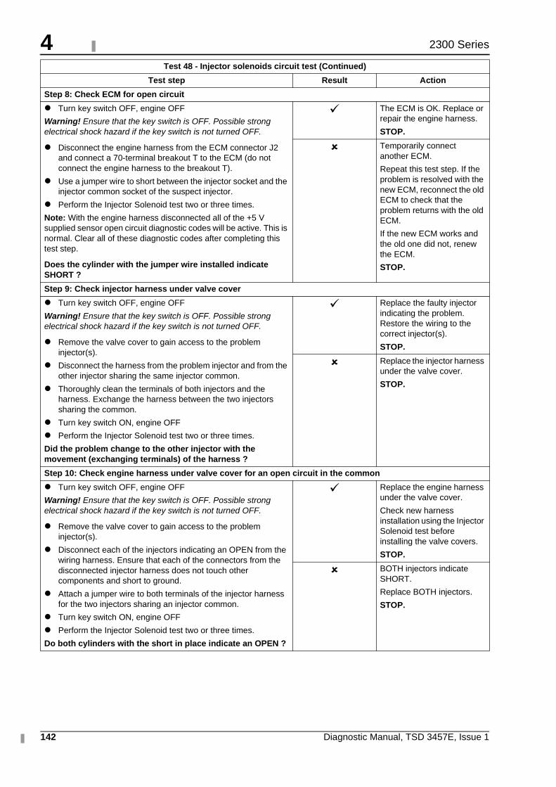
4
142 Diagnostic Manual, TSD 3457E, Issue 1
2300 Series
Step 8: Check ECM for open circuit
� Turn key switch OFF, engine OFF
Warning! Ensure that the key switch is OFF. Possible strong electrical shock hazard if the key switch is not turned OFF.
� Disconnect the engine harness from the ECM connector J2 and connect a 70-terminal breakout T to the ECM (do not connect the engine harness to the breakout T).
� Use a jumper wire to short between the injector socket and the injector common socket of the suspect injector.
� Perform the Injector Solenoid test two or three times.
Note: With the engine harness disconnected all of the +5 V supplied sensor open circuit diagnostic codes will be active. This is normal. Clear all of these diagnostic codes after completing this test step.
Does the cylinder with the jumper wire installed indicate SHORT ?
� The ECM is OK. Replace or repair the engine harness.
STOP.
� Temporarily connect another ECM.
Repeat this test step. If the problem is resolved with the new ECM, reconnect the old ECM to check that the problem returns with the old ECM.
If the new ECM works and the old one did not, renew the ECM.
STOP.
Step 9: Check injector harness under valve cover
� Turn key switch OFF, engine OFF
Warning! Ensure that the key switch is OFF. Possible strong electrical shock hazard if the key switch is not turned OFF.
� Remove the valve cover to gain access to the problem injector(s).
� Disconnect the harness from the problem injector and from the other injector sharing the same injector common.
� Thoroughly clean the terminals of both injectors and the harness. Exchange the harness between the two injectors sharing the common.
� Turn key switch ON, engine OFF
� Perform the Injector Solenoid test two or three times.
Did the problem change to the other injector with the movement (exchanging terminals) of the harness ?
� Replace the faulty injector indicating the problem. Restore the wiring to the correct injector(s).
STOP.
� Replace the injector harness under the valve cover.
STOP.
Step 10: Check engine harness under valve cover for an open circuit in the common
� Turn key switch OFF, engine OFF
Warning! Ensure that the key switch is OFF. Possible strong electrical shock hazard if the key switch is not turned OFF.
� Remove the valve cover to gain access to the problem injector(s).
� Disconnect each of the injectors indicating an OPEN from the wiring harness. Ensure that each of the connectors from the disconnected injector harness does not touch other components and short to ground.
� Attach a jumper wire to both terminals of the injector harness for the two injectors sharing an injector common.
� Turn key switch ON, engine OFF
� Perform the Injector Solenoid test two or three times.
Do both cylinders with the short in place indicate an OPEN ?
� Replace the engine harness under the valve cover.
Check new harness installation using the Injector Solenoid test before installing the valve covers.
STOP.
� BOTH injectors indicate SHORT.
Replace BOTH injectors.
STOP.
Test 48 - Injector solenoids circuit test (Continued)
Test step Result Action
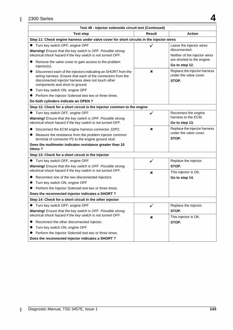
4
Diagnostic Manual, TSD 3457E, Issue 1 143
2300 Series
Step 11: Check engine harness under valve cover for short circuits in the injector wires
� Turn key switch OFF, engine OFF
Warning! Ensure that the key switch is OFF. Possible strong electrical shock hazard if the key switch is not turned OFF.
� Remove the valve cover to gain access to the problem injector(s).
� Disconnect each of the injectors indicating an SHORT from the wiring harness. Ensure that each of the connectors from the disconnected injector harness does not touch other components and short to ground.
� Turn key switch ON, engine OFF
� Perform the Injector Solenoid test two or three times.
Do both cylinders indicate an OPEN ?
� Leave the injector wires disconnected.
Neither of the injector wires are shorted to the engine.
Go to step 12.
� Replace the injector harness under the valve cover.
STOP.
Step 12: Check for a short circuit in the injector common to the engine
� Turn key switch OFF, engine OFF
Warning! Ensure that the key switch is OFF. Possible strong electrical shock hazard if the key switch is not turned OFF.
� Disconnect the ECM engine harness connector J2/P2.
� Measure the resistance from the problem injector common terminal of connector P2 to the engine ground stud.
Does the multimeter indicates resistance greater than 10 Ohms ?
� Reconnect the engine harness to the ECM.
Go to step 13.
� Replace the injector harness under the valve cover.
STOP.
Step 13: Check for a short circuit in the injector
� Turn key switch OFF, engine OFF
Warning! Ensure that the key switch is OFF. Possible strong electrical shock hazard if the key switch is not turned OFF.
� Reconnect one of the two disconnected injectors.
� Turn key switch ON, engine OFF
� Perform the Injector Solenoid test two or three times.
Does the reconnected injector indicates a SHORT ?
� Replace the injector.
STOP.
� This injector is OK.
Go to step 14.
Step 14: Check for a short circuit in the other injector
� Turn key switch OFF, engine OFF
Warning! Ensure that the key switch is OFF. Possible strong electrical shock hazard if the key switch is not turned OFF.
� Reconnect the other disconnected injector.
� Turn key switch ON, engine OFF
� Perform the Injector Solenoid test two or three times.
Does the reconnected injector indicates a SHORT ?
� Replace the injector.
STOP.
� This injector is OK.
STOP.
Test 48 - Injector solenoids circuit test (Continued)
Test step Result Action
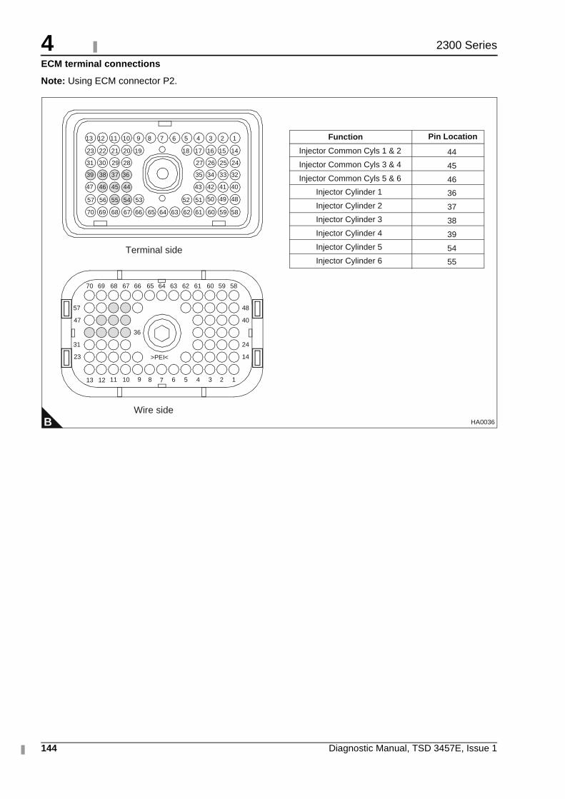
4
144 Diagnostic Manual, TSD 3457E, Issue 1
2300 Series
ECM terminal connections
Note: Using ECM connector P2.
B
1234568910111213
14
24
40
48
23
31
47
57
36
>PEI<
5859606162636566676870
13
64
51525354555657
40414243
32333435
24252627
44454647
36373839
28293031
14151617181920212223
123456789101112
69
5859606162636566676870 6469
7
Terminal side
Wire side
484950
Injector Common Cyls 1 & 2
Injector Common Cyls 3 & 4
Injector Common Cyls 5 & 6
Injector Cylinder 1
Injector Cylinder 2
Injector Cylinder 3
Injector Cylinder 4
Injector Cylinder 5
Injector Cylinder 6
44
45
46
36
37
38
39
54
55
Function Pin Location
HA0036
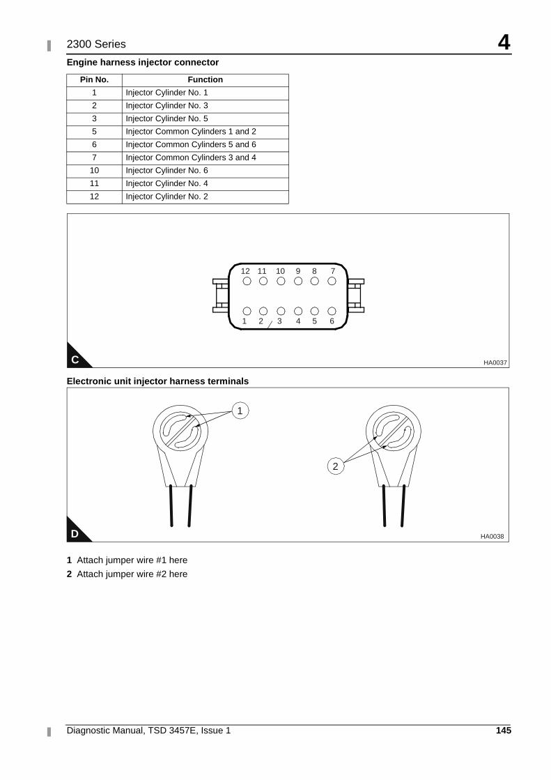
4
Diagnostic Manual, TSD 3457E, Issue 1 145
2300 Series
Engine harness injector connector
Electronic unit injector harness terminals
1 Attach jumper wire #1 here
2 Attach jumper wire #2 here
Pin No. Function
1 Injector Cylinder No. 1
2 Injector Cylinder No. 3
3 Injector Cylinder No. 5
5 Injector Common Cylinders 1 and 2
6 Injector Common Cylinders 5 and 6
7 Injector Common Cylinders 3 and 4
10 Injector Cylinder No. 6
11 Injector Cylinder No. 4
12 Injector Cylinder No. 2
C
12 11 10 9 8 7
1 2 3 4 5 6
HA0037
D
1
2
HA0038
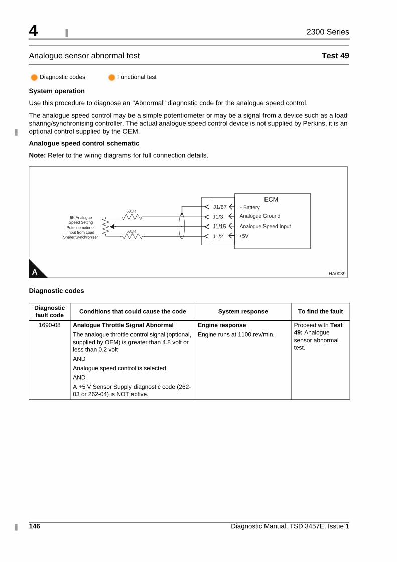
4
146 Diagnostic Manual, TSD 3457E, Issue 1
2300 Series
Analogue sensor abnormal test Test 49
System operation
Use this procedure to diagnose an "Abnormal" diagnostic code for the analogue speed control.
The analogue speed control may be a simple potentiometer or may be a signal from a device such as a load sharing/synchronising controller. The actual analogue speed control device is not supplied by Perkins, it is an optional control supplied by the OEM.
Analogue speed control schematic
Note: Refer to the wiring diagrams for full connection details.
Diagnostic codes
Diagnostic codes Functional test
Diagnostic fault code
Conditions that could cause the code System response To find the fault
1690-08 Analogue Throttle Signal Abnormal
The analogue throttle control signal (optional, supplied by OEM) is greater than 4.8 volt or less than 0.2 volt
AND
Analogue speed control is selected
AND
A +5 V Sensor Supply diagnostic code (262-03 or 262-04) is NOT active.
Engine response
Engine runs at 1100 rev/min.
Proceed with Test 49: Analogue sensor abnormal test.
A HA0039
5K AnalogueSpeed Setting
Potentiometer orInput from Load
Sharer/Synchroniser
J1/3
J1/15
J1/2
Analogue Ground
Analogue Speed Input
+5V
680R
680R
J1/67 - BatteryECM
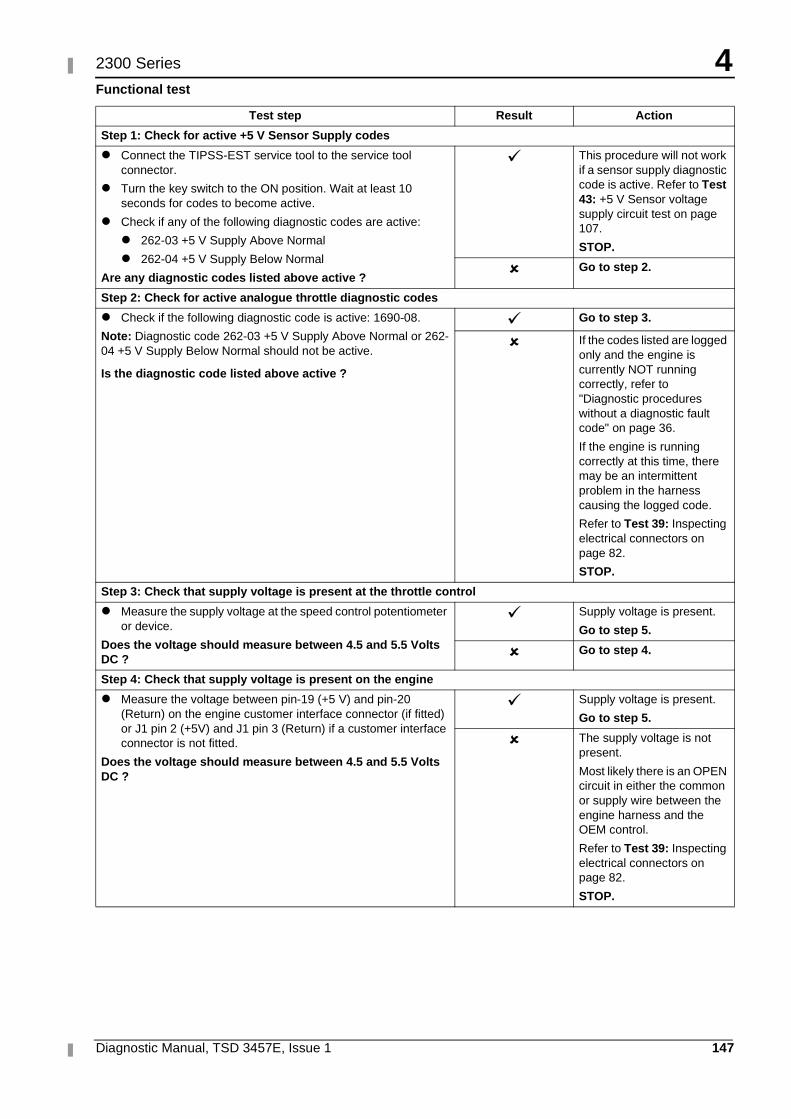
4
Diagnostic Manual, TSD 3457E, Issue 1 147
2300 Series
Functional test
Test step Result Action
Step 1: Check for active +5 V Sensor Supply codes
� Connect the TIPSS-EST service tool to the service tool connector.
� Turn the key switch to the ON position. Wait at least 10 seconds for codes to become active.
� Check if any of the following diagnostic codes are active:
� 262-03 +5 V Supply Above Normal
� 262-04 +5 V Supply Below Normal
Are any diagnostic codes listed above active ?
� This procedure will not work if a sensor supply diagnostic code is active. Refer to Test 43: +5 V Sensor voltage supply circuit test on page 107.
STOP.
� Go to step 2.
Step 2: Check for active analogue throttle diagnostic codes
� Check if the following diagnostic code is active: 1690-08.
Note: Diagnostic code 262-03 +5 V Supply Above Normal or 262-04 +5 V Supply Below Normal should not be active.
Is the diagnostic code listed above active ?
� Go to step 3.
� If the codes listed are logged only and the engine is currently NOT running correctly, refer to "Diagnostic procedures without a diagnostic fault code" on page 36.
If the engine is running correctly at this time, there may be an intermittent problem in the harness causing the logged code.
Refer to Test 39: Inspecting electrical connectors on page 82.
STOP.
Step 3: Check that supply voltage is present at the throttle control
� Measure the supply voltage at the speed control potentiometer or device.
Does the voltage should measure between 4.5 and 5.5 Volts DC ?
� Supply voltage is present.
Go to step 5.
� Go to step 4.
Step 4: Check that supply voltage is present on the engine
� Measure the voltage between pin-19 (+5 V) and pin-20 (Return) on the engine customer interface connector (if fitted) or J1 pin 2 (+5V) and J1 pin 3 (Return) if a customer interface connector is not fitted.
Does the voltage should measure between 4.5 and 5.5 Volts DC ?
� Supply voltage is present.
Go to step 5.
� The supply voltage is not present.
Most likely there is an OPEN circuit in either the common or supply wire between the engine harness and the OEM control.
Refer to Test 39: Inspecting electrical connectors on page 82.
STOP.
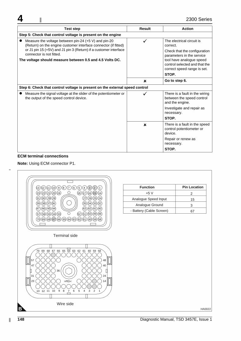
4
148 Diagnostic Manual, TSD 3457E, Issue 1
2300 Series
ECM terminal connections
Note: Using ECM connector P1.
Step 5: Check that control voltage is present on the engine
� Measure the voltage between pin-24 (+5 V) and pin-20 (Return) on the engine customer interface connector (if fitted) or J1 pin 15 (+5V) and J1 pin 3 (Return) if a customer interface connector is not fitted.
The voltage should measure between 0.5 and 4.5 Volts DC.
� The electrical circuit is correct.
Check that the configuration parameters in the service tool have analogue speed control selected and that the correct speed range is set.
STOP.
� Go to step 6.
Step 6: Check that control voltage is present on the external speed control
� Measure the signal voltage at the slider of the potentiometer or the output of the speed control device.
� There is a fault in the wiring between the speed control and the engine.
Investigate and repair as necessary.
STOP.
� There is a fault in the speed control potentiometer or device.
Repair or renew as necessary.
STOP.
Test step Result Action
B
1234568910111213
14
24
40
48
23
31
47
57
36
>PEI<
5859606162636566676870
13
64
51525354555657
40414243
32333435
24252627
44454647
36373839
28293031
14151617181920212223
123456789101112
69
5859606162636566676870 6469
7
Terminal side
Wire side
484950
+5 V
Analogue Speed Input
Analogue Ground
- Battery (Cable Screen)
2
15
3
67
Function Pin Location
HA0022
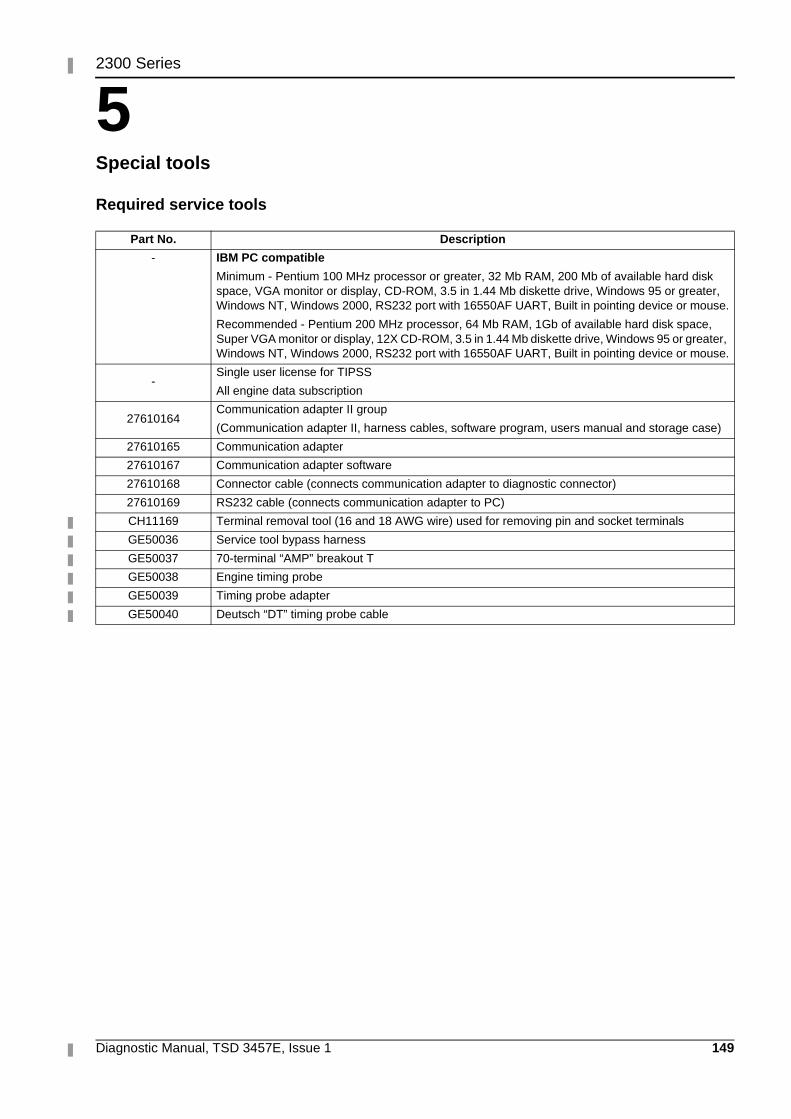
Diagnostic Manual, TSD 3457E, Issue 1 149
52300 Series
Special tools 5
Required service tools
Part No. Description
- IBM PC compatible
Minimum - Pentium 100 MHz processor or greater, 32 Mb RAM, 200 Mb of available hard disk space, VGA monitor or display, CD-ROM, 3.5 in 1.44 Mb diskette drive, Windows 95 or greater, Windows NT, Windows 2000, RS232 port with 16550AF UART, Built in pointing device or mouse.
Recommended - Pentium 200 MHz processor, 64 Mb RAM, 1Gb of available hard disk space, Super VGA monitor or display, 12X CD-ROM, 3.5 in 1.44 Mb diskette drive, Windows 95 or greater, Windows NT, Windows 2000, RS232 port with 16550AF UART, Built in pointing device or mouse.
-Single user license for TIPSS
All engine data subscription
27610164Communication adapter II group
(Communication adapter II, harness cables, software program, users manual and storage case)
27610165 Communication adapter
27610167 Communication adapter software
27610168 Connector cable (connects communication adapter to diagnostic connector)
27610169 RS232 cable (connects communication adapter to PC)
CH11169 Terminal removal tool (16 and 18 AWG wire) used for removing pin and socket terminals
GE50036 Service tool bypass harness
GE50037 70-terminal “AMP” breakout T
GE50038 Engine timing probe
GE50039 Timing probe adapter
GE50040 Deutsch “DT” timing probe cable
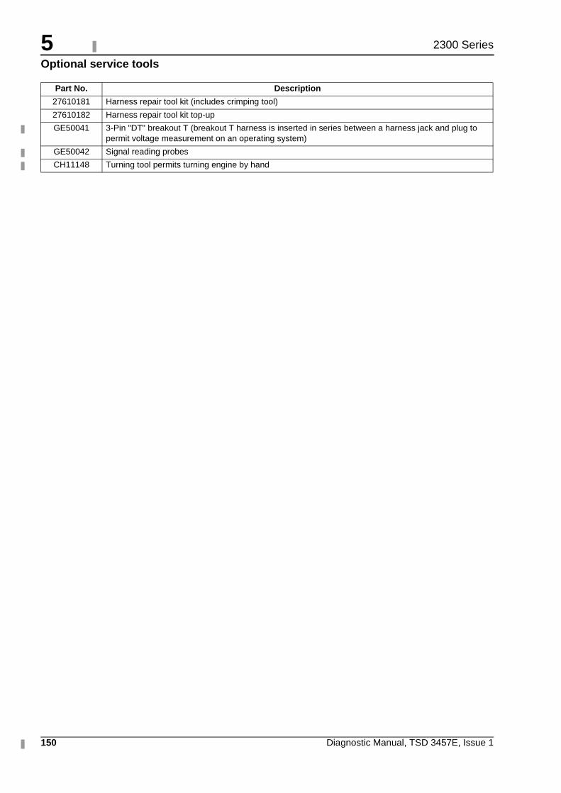
5
150 Diagnostic Manual, TSD 3457E, Issue 1
2300 Series
Optional service tools
Part No. Description
27610181 Harness repair tool kit (includes crimping tool)
27610182 Harness repair tool kit top-up
GE50041 3-Pin "DT" breakout T (breakout T harness is inserted in series between a harness jack and plug to permit voltage measurement on an operating system)
GE50042 Signal reading probes
CH11148 Turning tool permits turning engine by hand